WO2016152358A1 - 画像処理装置、画像処理方法及び画像処理プログラム - Google Patents
画像処理装置、画像処理方法及び画像処理プログラム Download PDFInfo
- Publication number
- WO2016152358A1 WO2016152358A1 PCT/JP2016/055165 JP2016055165W WO2016152358A1 WO 2016152358 A1 WO2016152358 A1 WO 2016152358A1 JP 2016055165 W JP2016055165 W JP 2016055165W WO 2016152358 A1 WO2016152358 A1 WO 2016152358A1
- Authority
- WO
- WIPO (PCT)
- Prior art keywords
- frame
- resolution
- image
- super
- positional deviation
- Prior art date
- Legal status (The legal status is an assumption and is not a legal conclusion. Google has not performed a legal analysis and makes no representation as to the accuracy of the status listed.)
- Ceased
Links
Images






Classifications
-
- G—PHYSICS
- G06—COMPUTING OR CALCULATING; COUNTING
- G06T—IMAGE DATA PROCESSING OR GENERATION, IN GENERAL
- G06T3/00—Geometric image transformations in the plane of the image
- G06T3/40—Scaling of whole images or parts thereof, e.g. expanding or contracting
-
- H—ELECTRICITY
- H04—ELECTRIC COMMUNICATION TECHNIQUE
- H04N—PICTORIAL COMMUNICATION, e.g. TELEVISION
- H04N5/00—Details of television systems
- H04N5/14—Picture signal circuitry for video frequency region
-
- H—ELECTRICITY
- H04—ELECTRIC COMMUNICATION TECHNIQUE
- H04N—PICTORIAL COMMUNICATION, e.g. TELEVISION
- H04N7/00—Television systems
- H04N7/01—Conversion of standards, e.g. involving analogue television standards or digital television standards processed at pixel level
Definitions
- the present invention relates to an image processing technique, and more particularly to a technique for converting the resolution of an image.
- Some recent digital cameras and video cameras have a high-speed shooting function with a high frame rate exceeding 60 fps. By shooting at a high shutter speed, it is used to capture a momentary movement or to shoot a scene that you do not want to miss.
- the frame rate is set in consideration of the upper limit of the reading speed of an image sensor such as CMOS and the writing speed of a recording medium such as DDR-SDRAM. The higher the value, the smaller the resolution per frame.
- a super-resolution process that generates a high-resolution image using a plurality of low-resolution images is known as a method for providing a clear and high-quality image when such a low-resolution image is enlarged and displayed.
- it is difficult to generate interpolated pixels in a high-resolution image generated by super-resolution processing unless there is a certain amount of camera shake or positional displacement between multiple low-resolution images. . For this reason, in the case of an image with a high frame rate, since high-speed shooting is performed, there is almost no positional deviation depending on the subject, and it is difficult to generate a high-resolution high-resolution image even if super-resolution processing is performed.
- Patent Document 1 discloses a technique for detecting a frame rate and determining to increase the number of reference frames of a moving image used for super-resolution processing as the frame rate increases.
- the present embodiment has been made in view of such circumstances, and an object thereof is to provide an image processing technique capable of generating a high-resolution high-resolution image using an image taken at high speed.
- an image processing apparatus selects an image input unit that stores a moving image in a memory, and a predetermined number of reference frames used for super-resolution processing from the moving image. And a super-resolution processing unit that generates a high-resolution image having a resolution higher than that of the reference frame by performing super-resolution processing on the predetermined number of reference frames.
- the reference frame determining unit determines a frame interval of reference frames to be selected based on a value indicating a degree of pixel positional deviation in the moving image frame.
- Another aspect of the present embodiment is an image processing method.
- This method includes an image input step for storing a moving image in a memory, a reference frame determination step for selecting a predetermined number of reference frames to be used for super-resolution processing from the moving image, and a superframe for the predetermined number of reference frames. And a super-resolution processing step of generating a high-resolution image having a resolution higher than that of the reference frame by performing the resolution processing.
- a frame interval of reference frames to be selected is determined based on a value indicating the degree of pixel positional deviation in the moving image frame.
- a high-resolution high-resolution image can be generated using an image taken at high speed.
- FIG. 6A to FIG. 6C are diagrams for explaining the relationship between a user-designated frame, a start frame, and an end frame.
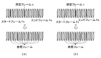
- FIG. 7A and FIG. 7B are diagrams for explaining a reference frame determined based on a frame interval. It is a flowchart which shows the detailed procedure of the super-resolution process of FIG. It is a flowchart which shows the detailed procedure of the iterative back projection method of FIG.
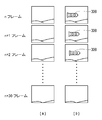
- FIG. 10A and FIG. 10B are diagrams for explaining frames of moving images having different moving speeds of the subject. 6 is a flowchart showing a detailed procedure of reference frame determination processing in FIG. 2 in the case of Example 2. It is a flowchart which shows the procedure of the processing routine A of FIG. 11A. It is a flowchart which shows the procedure of the processing routine B of FIG. 11A.
- FIG. 1 is a configuration diagram of an image processing apparatus 100 according to the present embodiment.
- the image processing apparatus 100 includes an image input unit 10, a storage unit 20, a super-resolution processing unit 30, a display unit 40, a frame rate detection unit 50, and a reference frame determination unit 60. These configurations are realized by hardware, software, or a combination thereof.
- the image input unit 10 acquires a moving image captured by a camera or the like, and stores each frame of the moving image in the storage unit 20.
- the frame rate detection unit 50 detects the frame rate of the moving image stored in the storage unit 20 and gives it to the reference frame determination unit 60.
- the frame rate is a value defined by the shutter speed at the time of moving image shooting (in other words, the capture speed), and does not indicate the frame rate at the time of reproduction.
- the reference frame determination unit 60 determines a plurality of reference frames used for the super-resolution processing based on the frame rate given from the frame rate detection unit 50.
- the reference frame determination unit 60 detects a pixel position shift of the frame of the moving image stored in the storage unit 20, and selects a reference frame so that the position shift becomes a predetermined amount.
- the super-resolution processing unit 30 reads a plurality of reference frames of the moving image determined by the reference frame determination unit 60 from the storage unit 20, performs super-resolution processing on each reference frame, and has a resolution higher than that of the reference frame.
- a high-resolution image is generated and stored in the storage unit 20.
- the display unit 40 displays the high resolution image stored in the storage unit 20.
- the super-resolution processing unit 30 performs reconfiguration-type super-resolution processing on each input reference frame and converts it into a high-resolution image. Specifically, an estimated low resolution image is obtained from the n-th high-resolution image using a point spread function, and an error between the estimated low-resolution image and the actual captured image is converted into an n-th high-resolution image using a back projection function. The image is updated to the (n + 1) -th high-resolution image by back projection. This process is repeated to reconstruct a high resolution image.
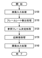
- FIG. 2 is a flowchart showing an image processing procedure performed by the image processing apparatus 100. The operation of each component of the image processing apparatus 100 will be described with reference to the flowchart.
- the image input unit 10 inputs a captured moving image, and stores each frame of the moving image in the storage unit 20 (step S100).
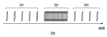
- FIG. 3 is a diagram for explaining the format of a moving image input by the image input unit 10.
- the horizontal axis indicates time.
- normal frame rate frame groups 201 and 203 and a high-speed frame rate frame group 202 captured at high speed are mixed.
- the normal frame rate is a frame rate generally adopted by the photographing apparatus such as 24 fps, 30 fps, and 60 fps.
- the high frame rate refers to a frame rate taken at a high shutter speed such as 240 fps, 400 fps, 600 fps, and 1200 fps.
- the resolution of images shot at the high frame rate becomes lower in accordance with the frame rate.
- the user plays a moving image, performs an operation such as pausing at an arbitrary frame, and designates a frame for which some processing (for example, display or editing) is to be performed.
- some processing for example, display or editing
- subsequent processing starts.
- the frame rate detection unit 50 detects the frame rate in the frame specified by the user (S110).
- the frame rate may be detected by measuring a vertical synchronization signal of a moving image, or the frame rate may be acquired from frame rate information added to the moving image.
- the reference frame determination unit 60 determines a start frame and an end frame based on the detected frame rate, performs motion estimation to check whether there is a predetermined amount of positional deviation between the start frame and the end frame, A frame interval of reference frames used in the super-resolution processing is determined (S120). Details of the reference frame determination process in step S120 will be described later.
- the super-resolution processor 30 reads a plurality of reference frames of the moving image based on the determined frame interval, performs super-resolution processing on each reference frame, and generates a high-resolution image (S130).
- the display unit 40 displays the generated high resolution image on the display device (S140). As a result, the frame on which the user has performed an operation such as a pause is displayed on the display device with high resolution.
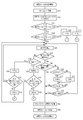
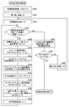
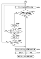
- 4A to 4C are flowcharts showing the detailed procedure of the reference frame determination process in step S120 of FIG.
- the frame rate detected by the frame rate detection process in step S110 of FIG. 2 is acquired (S10).
- This detected frame rate is the frame rate of the frame n designated by the user.
- initial values of a start frame Fs and an end frame Fe that are used when detecting a displacement described later are obtained (S12).
- the interval between the initial values of the start frame Fs and the end frame Fe is set to a value according to the frame rate.
- FIG. 5 is a diagram for explaining a table storing the initial value intervals of the start frame Fs and the end frame Fe in association with the frame rate.
- the interval between the initial values of the start frame Fs and the end frame Fe is increased in proportion to the frame rate. For example, as the frame rate becomes 240 fps, 300 fps, 600 fps, 1200 fps, the interval between the initial values of the start frame Fs and the end frame Fe is increased to 2, 3, 4, 5.
- FIG. 6A to FIG. 6C are diagrams for explaining the relationship between the user-designated frame n, the start frame Fs, and the end frame Fe.
- a normal frame rate frame group 201 a high frame rate frame group 202, and a normal frame rate frame group 203 are arranged in this order.
- the high frame rate frame group 202 starts with the n_sth frame and ends with the n_eth frame.
- the nth designated frame designated by the user is one of the frames in the high-speed frame rate group 202.
- the start frame Fs and the end frame Fe are at positions sandwiching the designated frame n.
- the interval between the initial values of the start frame Fs and the end frame Fe is 2 in this example, but the interval between the initial values varies depending on the frame rate as shown in FIG.
- FIG. 6B shows a case where the designated frame n is a frame that switches from the normal frame rate to the high-speed frame rate (the first frame n_s of the frame group 202 at the high-speed frame rate).
- FIG. 6C shows a case where the designated frame n is a frame that switches from the high frame rate to the normal frame rate (the last frame n_e of the frame group 202 at the high frame rate).
- step S12 It is determined whether the start frame Fs and the end frame Fe determined in step S12 have the same frame rate as the designated frame n (S14, S16).
- the process proceeds to step S22 to detect misalignment.
- the start frame Fs is not in the frame group of the high-speed frame rate to which the designated frame n belongs, but the frame at the previous normal frame rate. In the group. In this case, the start frame Fs is set to the first frame n_s of the high-speed frame rate frame group to which the designated frame n belongs (S18), and then the process proceeds to the processing routine A of FIG. 4B.
- the end frame Fe When the frame rate of the end frame Fe is different from the frame rate of the designated frame n (No in S16), the end frame Fe is not in the frame group of the high-speed frame rate to which the designated frame n belongs, but the subsequent frame group of the normal frame rate. It is in. In this case, the end frame Fe is set to the last frame n_e of the high-speed frame rate frame group to which the designated frame n belongs (S20), and then the process proceeds to the processing routine B in FIG. 4C.
- the start frame Fs is set to the first frame n_s.
- the end frame Fe is set to the last frame n_e.
- Detect misalignment between the start frame Fs and the end frame Fe (S22).
- a displacement detection method for example, there is a method of estimating the displacement amount of the entire image between frames using a known representative point matching method or a phase-only correlation method used in camera motion estimation or the like. Misregistration detection is performed in units of subpixels.
- the detected displacement amount is at least one pixel in the horizontal direction or the vertical direction (S24).
- is obtained and compared (S26).
- the frame number of the end frame Fe is added by the predetermined frame number ⁇ and updated (S28). If
- the predetermined frame number ⁇ is a variable, but ⁇ may be 1 and may be changed according to the detected frame rate.
- the start frame Fs is set to the first frame n_s of the frame group having the high frame rate to which the designated frame n belongs (S36). Thereafter, the process proceeds to processing routine A of FIG. 4B.
- the end frame Fe is set to the last frame n_e of the frame group having the high frame rate to which the designated frame n belongs (S38). Thereafter, the process proceeds to the processing routine B of FIG. 4C.
- step S24 If it is determined in step S24 that the displacement amount is 1 pixel or more (Yes in S24), it is determined whether the displacement amount is equal to or less than a threshold value (S40).
- a threshold value is arbitrary, if the amount of positional deviation is too large, there is a high possibility of erroneous detection when estimating the position of super-resolution processing described later, so the threshold value should be set to a small value such as 2 pixels. Is preferred.
- step S50 the frame interval Fd is calculated from the start frame Fs and the end frame Fe.
- the frame interval Fd is a frame interval when a plurality of reference frames used in super-resolution processing are selected from a moving image. The calculation method of the frame interval in step S52 will be described later.
- step S52 the frame interval Fd is calculated from the start frame Fs and the end frame Fe by the following equation.
- Fd
- N is the number of reference frames to be used.
- the number of reference frames may be specified in advance for each frame rate, and the number of reference frames may be determined according to the detected frame rate. Generally, the higher the frame rate, the lower the resolution of the image. By increasing the number of reference frames as the frame rate increases, the quality of a high-resolution image generated from a low-resolution reference frame can be improved.
- the enlargement magnification may be obtained from the resolution of the image output to the display and the resolution of the current frame rate, and the number of reference frames may be determined based on the magnification. By increasing the number of reference frames as the magnification increases, a high-resolution image with high image quality can be generated in accordance with the high resolution of the display.
- Fd 1.
- Fd 1.
- the reference frame number N may be automatically updated.
- the reference frame N is updated to the absolute difference
- 7 (a) and 7 (b) are diagrams for explaining the reference frame determined based on the frame interval Fd.
- FIG. 7A shows a case where the start frame Fs is finally (n ⁇ 8) th and the end frame Fe is (n + 8) th by the reference frame determination process for the nth designated frame.
- the frame interval Fd is
- the reference frame is selected starting from the start frame Fs with two frame intervals. At this time, the designated frame n is always selected as a reference frame.
- FIG. 7B shows a case where the start frame Fs is finally (n-6) th and the end frame Fe is (n + 6) th by the reference frame determination process for the nth designated frame.
- the frame interval Fd is
- reference frames are selected at a rate of 2 frames every 3 frames. At this time, the designated frame n is always selected as a reference frame.
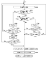
- FIG. 4B is a flowchart showing the procedure of the processing routine A in FIG. 4A.
- the processing routine A is a misregistration detection routine that is called when the start frame Fs is set to the first frame n_s of the frame group of the high-speed frame rate to which the designated frame n belongs in step S18 or step S36 of FIG. 4A. .
- the end frame Fe is moved back and forth while the start frame Fs is fixed to the first frame n_s so that a predetermined positional deviation amount is obtained.
- the positional deviation is detected between the start frame Fs fixed to the first frame n_s and the end frame Fe (S60A). It is determined whether or not the detected displacement amount is at least one pixel in the horizontal direction or the vertical direction (S62A). When the amount of displacement is less than one pixel (No in S62A), the frame number of the end frame Fe is added by the predetermined frame number ⁇ and updated (S64A).
- the end frame Fe is set to the last frame n_e of the high-speed frame rate frame group to which the designated frame n belongs (S68A). .
- the process proceeds to step S80A, and the frame interval is calculated. If the combination of the start frame Fs and the end frame Fe has not been found (No in S70A), the process returns to step S60A, and the position shift is detected for the combination of the start frame Fs and the end frame Fe.
- step S62A If it is determined in step S62A that the displacement amount is 1 pixel or more (Yes in S62A), it is determined whether the displacement amount is equal to or less than a threshold value (S72A). If the amount of displacement is equal to or less than the threshold (Yes in S72A), the process proceeds to step S80A, and the frame interval Fd is calculated from the start frame Fs and the end frame Fe.
- the frame number of the end frame Fe is subtracted by 1 and updated (S74A). After the update, it is determined whether or not the absolute difference
- step S78A When the combination of the start frame Fs and the end frame Fe has already appeared (Yes in S78A), the process proceeds to step S80A, and the frame interval is calculated. When the combination of the start frame Fs and the end frame Fe has not been found (No in S78A), the process returns to step S60A, and the positional deviation is detected for the updated combination of the start frame Fs and the end frame Fe.
- FIG. 4C is a flowchart showing the procedure of the processing routine B in FIG. 4A.
- the processing routine B is a positional deviation detection routine that is called when the end frame Fe is set to the last frame n_e of the frame group of the high-speed frame rate to which the designated frame n belongs in step S20 or step S38 of FIG. 4A. .
- the end frame Fe is fixed to the last frame n_e, and the start frame Fs is moved back and forth to adjust to a predetermined positional deviation amount.
- the position shift is detected between the start frame Fs and the end frame Fe fixed to the last frame n_e (S60B). It is determined whether or not the detected displacement amount is at least one pixel in the horizontal direction or the vertical direction (S62B). If the amount of displacement is less than one pixel (No in S62B), the frame number of the start frame Fs is updated by subtracting the predetermined frame number ⁇ (S64B).
- the start frame Fs is set to the first frame n_s of the frame group having the high frame rate to which the designated frame n belongs (S68B). .
- the process proceeds to step S80B, and the frame interval is calculated. If the combination of the start frame Fs and the end frame Fe has not been found (No in S70B), the process returns to step S60B, and the position shift is detected for the combination of the start frame Fs and the end frame Fe.
- step S62B If it is determined in step S62B that the displacement amount is 1 pixel or more (Yes in S62B), it is determined whether the displacement amount is equal to or less than a threshold value (S72B). If the amount of positional deviation is equal to or smaller than the threshold (Yes in S72B), the process proceeds to step S80B, and the frame interval Fd is calculated from the start frame Fs and the end frame Fe.
- the frame number of the start frame Fs is added by 1 and updated (S74B). After the update, it is determined whether or not the absolute difference
- step S78B the process proceeds to step S80B, and the frame interval is calculated.
- the process returns to step S60B, and the positional deviation is detected for the updated combination of the start frame Fs and the end frame Fe.
- FIG. 8 is a flowchart showing a detailed procedure of the super-resolution processing in step S130 of FIG.
- IBP iterative back projection
- a point spread function PSF, a back projection (back projection) function BP, and a magnification r for enlarging the image are determined (see FIG. 2). S200).
- PSF and BP it is necessary to select PSF and BP according to the magnification, and in high-speed shooting, the resolution that can be shot is determined according to the frame rate. Therefore, the point spread function PSF and the back projection function BP are determined based on the frame rate. become.
- the point spread function PSF and the back projection function BP may be acquired in advance from a video camera that has been shot, or may be recorded in advance.
- the magnification r is obtained from the ratio between the designated output resolution such as the resolution of the video display device of the output destination and the resolution determined according to the frame rate of the moving image.
- the magnification r may be obtained from the ratio between the resolution of the normal frame rate image and the resolution of the high frame rate image. In this case, if the resolution of the image is proportional to the frame rate, the magnification r can be obtained from the ratio between the normal frame rate and the high-speed frame rate.
- a positional deviation estimation in units of sub-pixels is performed on a plurality of reference frames (including a user-designated frame n) selected in the reference frame determination process in step S120 of FIG. 2 (S210).
- a positional deviation estimation method a positional deviation due to camera movement is estimated using a known representative point matching method or phase-only correlation method used in camera movement estimation or the like.
- the result of the positional deviation estimation already performed in the reference frame determination process in step S120 may be used.
- the estimated amount of misalignment between the start frame Fs and the end frame Fe last performed in the reference frame determination process in step S120 is equally divided among the N reference frames selected in the reference frame determination process. It is also possible to use an estimated amount of displacement of each reference frame. For example, when the frame rate is equal to or higher than the threshold value, the above-described equal division calculation is performed assuming constant velocity linear motion. Thereby, it is possible to simplify the position shift estimation and execute the super-resolution processing at high speed.
- the difference in frame number between the nine reference frames selected in the reference frame determination step and the designated frame n is ⁇ 8, ⁇ 6, ⁇ 4, ⁇ 2, 0, 2, 4, 6, 8 from the left.
- the positional deviation amount of the designated frame n is set to (0, 0), and the difference between the respective frame numbers is multiplied by a positional deviation amount of 0.0625 per frame.
- the amount of displacement is ( ⁇ 0.5, ⁇ 0.5), ( ⁇ 0.375, ⁇ 0.375), ( ⁇ 0.25, ⁇ 0.25), ( ⁇ 0.125, ⁇ 0. 125), (0, 0), (0.125, 0.125), (0.25, 0.25), (0.375, 0.375), (0.5, 0.5) .
- an initial high resolution image is generated by super-resolution processing by the IBP method (S220).
- an estimated low resolution image is generated by reducing the estimated high resolution image to match the resolution of the captured image using a point spread function PSF.
- the difference between the generated estimated low-resolution image and the actual captured image is taken, and the high-resolution image is updated by iterative processing of adding the error to the estimated high-resolution image after applying the back projection function BP.
- the initial high resolution image is generated.
- an initial value of the high-resolution image is necessary, and a user-specified frame can be enlarged and used.
- the initial value high-resolution image may be any image, and the method of providing the high-resolution image as the initial value is not limited to this.
- enlargement processing to a high resolution image is performed by the IBP method (S230).
- FIG. 9 is a flowchart showing a detailed procedure of the iterative backprojection method in step S230 of FIG.
- the initial high-resolution image created in step S220 of FIG. 8 is input and set as the first estimated high-resolution image f0 (S300).
- the number of repetitions i is initialized to 0 (S302).
- the number n of reference frames is initialized to 0 (S304). It is determined whether or not the number of reference frames has reached the designated number N (S306). When the number of reference frames has not reached the designated number N (No in S306), the number of reference frames is estimated based on the estimated positional deviation amount dn of the reference frame n determined in the reference frame positional deviation estimation processing in step S210 of FIG. The pixels of the high resolution image f are shifted (S308). At this time, since the displacement amount obtained in step S210 is the displacement amount in the low-resolution image, it is used after being converted into the displacement amount in the high-resolution image by multiplying the magnification.
- Convolution (convolution integration) of the point spread function PSF is performed on the pixel-shifted estimated high-resolution image (S310).
- the PSF used here is the PSF selected based on the frame rate in step S200 of FIG.
- the downsampling is performed so that the resolution of the captured image is obtained, and an estimated low resolution image is created (S312).
- the difference between the estimated low resolution image and the reference frame n that is the actual captured image is calculated to create a differential low resolution image (S314).
- the differential low resolution image is up-sampled to generate a differential high resolution image (S316).
- the back projection function BP is convolved with the upsampled differential high resolution image (S318).
- the BP used here is the BP selected based on the frame rate in step S200 of FIG.
- the differential high resolution image convolved with BP is shifted in the direction opposite to the initial shift direction based on the amount of displacement (S320).
- step S306 when the number of reference frames reaches the designated number N (Yes in S306), the difference high resolution image shifted in the reverse direction in step S320 is added to the estimated high resolution image to obtain the estimated high resolution image.
- Update (S324).
- S326 it is determined whether an end condition has been reached (S326).
- the end condition for example, conditions such as whether or not the specified number of repetitions has been reached and whether or not the average value of each differential low-resolution image has become equal to or less than a threshold value are set. If the end condition is not satisfied (No in S326), the number of repetitions i is increased by 1 (S328), the process returns to Step S304, and the subsequent processing is repeated.
- the end condition is satisfied (Yes in S326), the process of the iterative backprojection method is ended, and the generated estimated high resolution image is output as a final high resolution image.
- the image enlargement process by the IBP method in step S230 of FIG. 8 is completed, a high-resolution image is output, and the super-resolution process is completed.
- the high-resolution image obtained by the super-resolution process in step S130 in FIG. 2 is output and displayed on a display or the like in the image output process in step S140. This makes it possible to output a high-quality high-resolution image from a designated frame regardless of the subject, shooting conditions, and individual differences among photographers even during high-speed shooting.
- the frame interval of the reference frames so as to have a predetermined positional deviation amount
- Shooting using a high frame rate is performed under various circumstances. There are cases where a subject moving at high speed is photographed, and there is a case where high-speed photographing is performed in order to photograph a decisive moment with a low-speed subject.
- Example 2 In the first embodiment, the amount of positional deviation of the entire image is estimated, and the frame interval Fd of the reference frame used for the super-resolution processing is determined.
- FIG. 10A there may be a case where it takes 30 frames for the amount of displacement by one pixel in the horizontal and vertical directions due to camera shake, as shown in FIG. 10B.
- the moving object 300 moves at a high speed within several frames. In the latter case, it is better to estimate the movement of the moving subject 300 than to estimate the positional deviation amount from the movement of the camera such as camera shake.
- a method for determining the frame interval Fd by paying attention to the movement of the subject will be described. The description of the configuration and operation common to the first embodiment is omitted as appropriate.
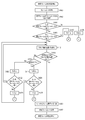
- 11A to 11C are flowcharts showing the detailed procedure of the reference frame determination process in step S120 of FIG. 2 in the case of the second embodiment.
- the positional deviation is detected for each block.
- the frame rate detected by the frame rate detection process in step S110 of FIG. 2 is acquired (S400).
- Initial values of the start frame Fs and the end frame Fe are obtained from the designated frame n and the detected frame rate (S402).
- step S402 It is determined whether the start frame Fs and the end frame Fe determined in step S402 have the same frame rate as the designated frame n (S404, S406).
- the process proceeds to step S412 to detect the positional deviation for each block.
- the start frame Fs is set to the first frame n_s of the frame group having the high frame rate to which the designated frame n belongs (S408). Thereafter, the process proceeds to the processing routine A of FIG. 11B.
- the end frame Fe is set to the last frame n_e of the high-speed frame rate frame group to which the designated frame n belongs (S410). Thereafter, the process proceeds to the processing routine B of FIG. 11C.
- the position shift detection for each block is performed by block matching between the start frame Fs and the end frame Fe (S412).
- a frame image is divided into, for example, 8 ⁇ 8 blocks, and a motion vector is detected for each block.
- the motion vector of each block for example, it is determined whether or not a positional deviation has occurred by one pixel or more in the horizontal direction and the vertical direction.
- a threshold value (S414).
- the threshold is set to 5 blocks, for example. In high-speed shooting, since the resolution that can be shot is determined according to the frame rate, this threshold value may be increased or decreased according to the frame rate. Alternatively, the total number of blocks in the frame is calculated in advance with reference to the frame rate, and it is determined whether or not the ratio of the blocks whose positional deviation amount is moving one pixel or more in the horizontal direction and the vertical direction is equal to or more than a threshold value. Also good.
- the start frame Fs is set to the first frame n_s of the frame group having the high frame rate to which the designated frame n belongs (S426). Thereafter, the process proceeds to the processing routine A of FIG. 11B.
- the end frame Fe is set to the last frame n_e of the frame group having the high frame rate to which the designated frame n belongs (S428). Thereafter, the process proceeds to the processing routine B of FIG. 11C.
- FIG. 11B is a flowchart showing the procedure of the processing routine A in FIG. 11A.
- the processing routine A is a misregistration detection routine that is called when the start frame Fs is set to the first frame n_s of the frame group of the high-speed frame rate to which the designated frame n belongs in step S408 or step S426 of FIG. 11A. .
- the position shift detection for each block is performed between the start frame Fs fixed to the first frame n_s and the end frame Fe (S440A). It is determined whether or not the number of blocks shifted by one pixel or more is greater than or equal to a threshold value (S442A). When the number of blocks shifted by one pixel or more is less than the threshold (No in S442A), the frame number of the end frame Fe is added by the predetermined frame number ⁇ and updated (S444A).
- the end frame Fe is set to the last frame n_e of the high-speed frame rate frame group to which the designated frame n belongs (S448A). .
- the process proceeds to step S452A, and the frame interval is calculated. If the combination of the start frame Fs and the end frame Fe has not been found (No in S450A), the process returns to step S440A, and the positional deviation detection for each block is performed for the combination of the start frame Fs and the end frame Fe.
- FIG. 11C is a flowchart showing the procedure of the processing routine B in FIG. 11A.
- the processing routine A is a positional deviation detection routine that is called when the end frame Fe is set to the last frame n_e of the frame group of the high-speed frame rate to which the designated frame n belongs in step S410 or step S428 in FIG. 11A. .
- the position shift detection for each block is performed between the start frame Fs and the end frame Fe fixed to the last frame n_e (S440B). It is determined whether or not the number of blocks shifted by one pixel or more is greater than or equal to a threshold value (S442B). When the number of blocks shifted by one pixel or more is less than the threshold (No in S442B), the frame number of the start frame Fs is updated by subtracting the predetermined frame number ⁇ (S444B).
- step S446B It is determined whether the start frame Fs after being updated by the predetermined number of frames ⁇ has the same frame rate as the designated frame n (S446B).
- the process proceeds to step S440B to detect the positional deviation for each block.
- the start frame Fs is set to the first frame n_s of the frame group having the high frame rate to which the designated frame n belongs (S448B). .
- the process proceeds to step S452B, and the frame interval is calculated. If the combination of the start frame Fs and the end frame Fe has not been found (No in S450B), the process returns to step S440B, and the positional deviation detection for each block is performed for the combination of the start frame Fs and the end frame Fe.
- the frame interval of a plurality of reference frames used for super-resolution processing is appropriately determined by detecting a positional shift in units of blocks, thereby achieving high resolution with high image quality.
- An image can be generated.
- the embodiment using the reconstruction-type super-resolution processing has been described.
- the super-resolution processing may be performed by other reconstruction-type super-resolution such as reconstruction-type super-resolution based on MAP (Maximum a posteriori) estimation, for example.
- a resolution method may be used.
- other methods such as a learning method may be used in addition to the reconstruction method.
- 10 image input unit 20 storage unit, 30 super-resolution processing unit, 40 display unit, 50 frame rate detection unit, 60 reference frame determination unit.
- the present invention can be used for a technique for converting the resolution of an image.
Landscapes
- Engineering & Computer Science (AREA)
- Multimedia (AREA)
- Signal Processing (AREA)
- Physics & Mathematics (AREA)
- General Physics & Mathematics (AREA)
- Theoretical Computer Science (AREA)
- Television Systems (AREA)
- Studio Devices (AREA)
- Image Processing (AREA)
- Picture Signal Circuits (AREA)
- Image Analysis (AREA)
Abstract
参照フレーム決定部(60)は、動画像から超解像処理に用いる所定枚数の参照フレームを選択する。超解像処理部(30)は、所定枚数の参照フレームに対して超解像処理を施すことにより、参照フレームよりも解像度の高い高解像度画像を生成する。参照フレーム決定部(60)は、動画像のフレームにおける画素の位置ずれ度合いを示す値にもとづいて、選択すべき参照フレームのフレーム間隔を決定する。
Description
本発明は、画像処理技術に関し、特に画像の解像度を変換する技術に関する。
近年のデジタルカメラやビデオカメラには、60fpsを超えるフレームレートの高い高速撮影機能を有するものがある。高速のシャッタスピードで撮影することで、瞬間の動きを捉えたり、撮り逃したくないシーンを撮影するために用いられる。通常、このような高速撮影ではフレームを記憶するためのデータ量が膨大になるため、CMOS等の撮像素子の読み出しスピードやDDR-SDRAM等の記録媒体の書き込み速度の上限を考慮し、フレームレートが高いほど1フレーム当たりの解像度を小さくして記録される。
一方、液晶ディスプレイ等の表示装置は高解像度化が進んでおり、前述した高フレームレートで撮影した低解像度画像を表示させる場合、表示装置に合わせ拡大する必要があり、拡大した場合、ぼけた画像になりユーザーに不鮮明な印象を与えてしまう。
このような低解像度画像の拡大表示の時、鮮明な高画質の画像を提供する方法として、複数枚の低解像度画像を用いて高解像度画像を生成する超解像処理が知られている。超解像処理では、複数枚の低解像度画像の間に、ある程度の手ぶれや被写体の移動等による位置ずれがないと超解像処理で生成される高解像度画像において補間画素を生成することは難しい。そのため、フレームレートが高い画像の場合、高速撮影されるために被写体によっては位置ずれがほとんど存在しなくなり、超解像処理を行っても高画質の高解像度画像を生成することが難しい。
特許文献1では、フレームレートを検出し、フレームレートが高いほど、超解像処理に用いる動画像の参照フレームの枚数を多くするように決定する技術が開示されている。
高速撮影の特性上、撮影対象や撮影状況、撮影者の個人差など個別の要因に応じて被写体の位置ずれ量が大幅に変化するため、フレームレートのみに依存して超解像処理に用いる動画像のフレームの枚数を調整する方法では、高画質の高解像度画像が得られないことがある。
本実施の形態はこうした状況に鑑みてなされたものであり、その目的は、高速撮影された画像を用いて高画質の高解像度画像を生成することのできる画像処理技術を提供することにある。
上記課題を解決するために、本実施の形態のある態様の画像処理装置は、動画像をメモリに格納する画像入力部と、前記動画像から超解像処理に用いる所定枚数の参照フレームを選択する参照フレーム決定部と、前記所定枚数の参照フレームに対して超解像処理を施すことにより、参照フレームよりも解像度の高い高解像度画像を生成する超解像処理部とを含む。前記参照フレーム決定部は、前記動画像のフレームにおける画素の位置ずれ度合いを示す値にもとづいて、選択すべき参照フレームのフレーム間隔を決定する。
本実施の形態の別の態様は、画像処理方法である。この方法は、動画像をメモリに格納する画像入力ステップと、前記動画像から超解像処理に用いる所定枚数の参照フレームを選択する参照フレーム決定ステップと、前記所定枚数の参照フレームに対して超解像処理を施すことにより、参照フレームよりも解像度の高い高解像度画像を生成する超解像処理ステップとを含む。前記参照フレーム決定ステップは、前記動画像のフレームにおける画素の位置ずれ度合いを示す値にもとづいて、選択すべき参照フレームのフレーム間隔を決定する。
なお、以上の構成要素の任意の組合せ、本実施の形態の表現を方法、装置、システム、記録媒体、コンピュータプログラムなどの間で変換したものもまた、本実施の形態の態様として有効である。
本実施の形態によれば、高速撮影された画像を用いて高画質の高解像度画像を生成することができる。
(実施例1)
図1は、本実施の形態に係る画像処理装置100の構成図である。画像処理装置100は、画像入力部10と、記憶部20と、超解像処理部30と、表示部40と、フレームレート検出部50と、参照フレーム決定部60とを含む。これらの構成は、ハードウェア、ソフトウェア、またはそれらの組合せにより実現される。
図1は、本実施の形態に係る画像処理装置100の構成図である。画像処理装置100は、画像入力部10と、記憶部20と、超解像処理部30と、表示部40と、フレームレート検出部50と、参照フレーム決定部60とを含む。これらの構成は、ハードウェア、ソフトウェア、またはそれらの組合せにより実現される。
画像入力部10は、カメラなどにより撮影された動画像を取得し、動画像の各フレームを記憶部20に格納する。
フレームレート検出部50は、記憶部20に格納された動画像のフレームレートを検出し、参照フレーム決定部60に与える。ここで、フレームレートとは動画像撮影時のシャッタスピード(言い換えればキャプチャスピード)により定義される値であり、再生時のフレームレートを指すものではない。
参照フレーム決定部60は、フレームレート検出部50から与えられたフレームレートにもとづいて超解像処理に用いる複数枚の参照フレームを決定する。参照フレーム決定部60は、記憶部20に格納された動画像のフレームの画素の位置ずれを検出し、位置ずれが所定量となるように参照フレームを選択する。
超解像処理部30は、参照フレーム決定部60により決定された動画像の複数の参照フレームを記憶部20から読み出し、各参照フレームに対して超解像処理を施し、参照フレームよりも解像度の高い高解像度画像を生成し、記憶部20に格納する。表示部40は、記憶部20に格納された高解像度画像を表示する。
超解像処理部30は、入力された各参照フレームに対して、再構成型の超解像処理を行い、高解像画像に変換する。具体的には、n回目の高解像度画像から点広がり関数を用いて推定低解像度画像を求め、推定低解像度画像と実際の撮影画像の誤差を逆投影関数を用いてn回目の高解像度画像に逆投影することにより(n+1)回目の高解像度画像に更新する。この処理を繰り返して高解像度画像を再構成する。
図2は、画像処理装置100による画像処理手順を示すフローチャートである。フローチャートを参照しながら、画像処理装置100の各構成の動作を説明する。
画像入力部10は、撮影された動画像を入力し、動画像の各フレームを記憶部20に格納する(ステップS100)。
図3は、画像入力部10により入力される動画像のフォーマットを説明する図である。横軸は時間を示す。動画像200には、通常フレームレートのフレーム群201、203と、高速撮影された高速フレームレートのフレーム群202とが混在する。
通常のフレームレートとは24fps、30fps、60fpsなど撮影装置が一般的に採用しているフレームレートである。高速フレームレートとは240fps、400fps、600fps、1200fpsなど高速のシャッタスピードで撮影されたフレームレートを指す。
通常フレームレートで撮影された画像の解像度と比較すると、高速フレームレートで撮影された画像の解像度はフレームレートに応じて解像度が低くなる。ユーザは、動画を再生し、任意のフレームで一時停止等の操作をして、何らかの処理(たとえば表示や編集)を行いたいフレームを指定する。ユーザーが任意のフレームで一時停止等の操作を行うと、それ以降の処理が開始する。
フレームレート検出部50は、ユーザによって指定されたフレームにおけるフレームレートを検出する(S110)。フレームレートの検出方法としては、例えば動画像の垂直同期信号を計測することでフレームレートを検出してもよく、あるいは、動画像に付加されたフレームレート情報からフレームレートを取得してもよい。
次に、参照フレーム決定部60は、検出されたフレームレートにもとづいてスタートフレームとエンドフレームを決定し、スタートフレームとエンドフレーム間で所定量の位置ずれがあるかどうかを調べる動き推定を行い、超解像処理で用いる参照フレームのフレーム間隔を決定する(S120)。ステップS120の参照フレーム決定処理の詳細は後述する。
超解像処理部30は、決定されたフレーム間隔にもとづいて動画像の複数の参照フレームを読み出し、各参照フレームに対して超解像処理を行い、高解像度画像を生成する(S130)。表示部40は、生成された高解像度画像を表示デバイスに表示する(S140)。これにより、ユーザが一時停止等の操作を行ったフレームが高解像度で表示デバイスに表示される。
図4A~図4Cは、図2のステップS120の参照フレーム決定処理の詳細な手順を示すフローチャートである。
まず、図2のステップS110のフレームレート検出処理で検出されたフレームレートを取得する(S10)。この検出されたフレームレートは、ユーザによる指定フレームnのフレームレートである。指定フレームnと検出されたフレームレートから、後述する位置ずれ検出の際に用いるスタートフレームFsとエンドフレームFeの初期値を求める(S12)。スタートフレームFsとエンドフレームFeの初期値の間隔は、フレームレートに応じた値に設定される。
図5は、フレームレートに対応づけて、スタートフレームFsとエンドフレームFeの初期値の間隔を格納したテーブルを説明する図である。フレームレートが大きくなるほど1フレームごとの動きは小さくなるので、フレームレートに比例して、スタートフレームFsとエンドフレームFeの初期値の間隔を大きくする。たとえば、フレームレートが240fps、300fps、600fps、1200fpsとなるにつれ、スタートフレームFsとエンドフレームFeの初期値の間隔を2、3、4、5と増加させる。
図6(a)~図6(c)は、ユーザによる指定フレームn、スタートフレームFs、おおよびエンドフレームFeの関係を説明する図である。動画像は通常フレームレートのフレーム群201、高速フレームレートのフレーム群202、通常フレームレートのフレーム群203がこの順で並んでいる。高速フレームレートのフレーム群202は、n_s番目のフレームから始まり、n_e番目のフレームで終わる。ユーザが指定したn番目の指定フレームは高速フレームレート群202のいずれかのフレームである。
一般に図6(a)に示すように、スタートフレームFsとエンドフレームFeは指定フレームnを挟む位置にある。スタートフレームFsとエンドフレームFeの初期値の間隔はこの例では2であるが、図5に示したようにフレームレートに応じて初期値の間隔は異なる。
ただし、ユーザの指定フレームnがフレームレートが変わる境界に位置する場合もある。図6(b)は、指定フレームnが、通常フレームレートから高速フレームレートに切り替わるフレーム(高速フレームレートのフレーム群202の最初のフレームn_s)である場合を示す。図6(c)は、指定フレームnが、高速フレームレートから通常フレームレートに切り替わるフレーム(高速フレームレートのフレーム群202の最後のフレームn_e)である場合を示す。
ステップS12で決定したスタートフレームFsとエンドフレームFeが指定フレームnと同じフレームレートであるかどうかを判定する(S14、S16)。スタートフレームFsとエンドフレームFeのフレームレートが指定フレームnのフレームレートと一致する場合(S14のYesかつS16のYes)はステップS22に進み、位置ずれ検出を行う。
スタートフレームFsのフレームレートが指定フレームnのフレームレートと異なる場合(S14のNo)、スタートフレームFsは、指定フレームnが属する高速フレームレートのフレーム群にはなく、その前の通常フレームレートのフレーム群にある。この場合、スタートフレームFsは、指定フレームnが属する高速フレームレートのフレーム群の最初のフレームn_sに設定され(S18)、その後、図4Bの処理ルーチンAに進む。
エンドフレームFeのフレームレートが指定フレームnのフレームレートと異なる場合(S16のNo)、エンドフレームFeは、指定フレームnが属する高速フレームレートのフレーム群にはなく、その後の通常フレームレートのフレーム群にある。この場合、エンドフレームFeは、指定フレームnが属する高速フレームレートのフレーム群の最後のフレームn_eに設定され(S20)、その後、図4Cの処理ルーチンBに進む。
これにより、図6(b)のように指定フレームnが高速フレームレートのフレーム群の最初のフレームn_sである場合、スタートフレームFsは最初のフレームn_sに設定される。また、図6(b)のように指定フレームnが高速フレームレートのフレーム群の最後のフレームn_eである場合、エンドフレームFeは最後のフレームn_eに設定される。
スタートフレームFsとエンドフレームFeの位置ずれ検出を行う(S22)。位置ずれ検出方法としては、たとえば、カメラの動き推定等で用いられる既知の代表点マッチング法や位相限定相関法などを用いてフレーム間での画像全体の位置ずれ量を推定する方法がある。位置ずれ検出はサブ画素単位で行う。
次に、検出された位置ずれ量が少なくとも水平方向もしくは垂直方向に1画素以上であるかどうかを判定する(S24)。位置ずれ量が1画素未満である場合(S24のNo)、指定フレームnとスタートフレームFsのフレーム番号の絶対差分|n-Fs|と、指定フレームとエンドフレームFeのフレーム番号の絶対差分|n-Fe|とを求めて比較する(S26)。
|n-Fs|≧|n-Fe|の場合(S26のYes)、エンドフレームFeのフレーム番号を所定フレーム数αだけ加算して更新する(S28)。|n-Fs|<|n-Fe|の場合(S26のNo)、スタートフレームFsのフレーム番号を所定フレーム数αだけ減算して更新する(S30)。所定フレーム数αは変数であるが、αは1でもよく、検出したフレームレートによって変更してもよい。
所定フレーム数αだけ更新した後のスタートフレームFs、エンドフレームFeが指定フレームnと同じフレームレートであるかどうかを判定する(S32、S34)。スタートフレームFs、エンドフレームFeのフレームレートが指定フレームnのフレームレートに一致する場合(S32のYes、S34のYes)、ステップS22に進み、位置ずれ検出を行う。
スタートフレームFsのフレームレートが指定フレームnのフレームレートと異なる場合(S32のNo)、スタートフレームFsは、指定フレームnが属する高速フレームレートのフレーム群の最初のフレームn_sに設定され(S36)、その後、図4Bの処理ルーチンAに進む。
エンドフレームFeのフレームレートが指定フレームnのフレームレートと異なる場合(S34のNo)、エンドフレームFeは、指定フレームnが属する高速フレームレートのフレーム群の最後のフレームn_eに設定され(S38)、その後、図4Cの処理ルーチンBに進む。
ステップS24で位置ずれ量が1画素以上である場合(S24のYes)、位置ずれ量が閾値以下であるかどうかを判定する(S40)。この閾値は任意であるが、位置ずれ量が大きすぎる場合、後述する超解像処理の位置推定の際、誤検出する可能性が高くなるため、閾値を例えば2画素など小さい値に設定することが好ましい。
位置ずれ量が閾値以下である場合(S40のYes)、ステップS52に進み、スタートフレームFsとエンドフレームFeからフレーム間隔Fdを計算する。フレーム間隔Fdは、超解像処理で用いる複数の参照フレームを動画像から選択する際のフレーム間隔である。ステップS52のフレーム間隔の計算方法については後述する。
位置ずれ量が閾値より大きい場合(S40のNo)、指定フレームnとスタートフレームFsのフレーム番号の絶対差分|n-Fs|と、指定フレームとエンドフレームFeのフレーム番号の絶対差分|n-Fe|とを求めて比較する(S42)。
|n-Fs|>|n-Fe|の場合(S42のYes)、スタートフレームFsのフレーム番号を1だけ加算して更新する(S44)。|n-Fs|≦|n-Fe|の場合(S42のNo)、エンドフレームFeのフレーム番号を1だけ減算して更新する(S46)。
更新後、スタートフレームFsとエンドフレームFeのフレーム番号の絶対差分|Fs-Fe|がN-1以下になるかどうか判定し(S48)、|Fs-Fe|≦N-1の場合(S48のYes)、ステップS52に進み、フレーム間隔を計算する。|Fs-Fe|>N-1の場合(S48のNo)、スタートフレームFsとエンドフレームFeの組合せについて既に位置ずれ検出を行ったかどうかを判定する(S50)。スタートフレームFsとエンドフレームFeの組合せが既出である場合(S50のYes)、ステップS52に進み、フレーム間隔を計算する。スタートフレームFsとエンドフレームFeの組合せが既出でない場合(S50のNo)、ステップS22に戻り、更新されたスタートフレームFsとエンドフレームFeの組合せについて位置ずれ検出を行う。
ステップS52において、スタートフレームFsとエンドフレームFeから次式によりフレーム間隔Fdを計算する。
Fd=|Fe-Fs|/(N-1)
Fd=|Fe-Fs|/(N-1)
ここでNは利用する参照フレームの枚数である。参照フレームの枚数はフレームレートごとにあらかじめ指定しておき、検出されたフレームレートに応じて参照フレームの枚数を決定してもよい。一般にフレームレートが高いほど画像の解像度が低い。フレームレートが高いほど参照フレームの枚数を多くすることで低解像度の参照フレームから生成される高解像度画像の品質を高めることができる。あるいは、ディスプレイに出力する画像の解像度と現在のフレームレートの解像度から拡大倍率を求め、その倍率をもとに参照フレームの枚数を決定してもよい。倍率が大きいほど参照フレームの枚数を増やすことでディスプレイの高解像度に合わせて高画質の高解像度画像を生成することができる。
このようにして求めたFdが1より小さい場合、Fd=1とする。Fdが1より小さい場合は、スタートフレームFsとエンドフレームFeとの間のフレーム枚数が参照フレームNの枚数より少ないことを示している。この場合、例えば、指定した参照フレーム枚数Nより少ないことをユーザに通知し、参照フレームNを更新して続けるか処理をやめるか入力させるようにしてもよい。もしくは自動的に、参照フレーム枚数Nを更新するようにしてもよい。更新する際には参照フレームNを絶対差分|Fs-Fe|に更新する。最後に、求めたフレーム間隔Fdから後述する超解像処理で利用するN枚の参照フレームを決定する(S54)。
図7(a)および図7(b)は、フレーム間隔Fdにもとづいて決定される参照フレームを説明する図である。
図7(a)は、n番目の指定フレームに対して、参照フレーム決定処理によって最終的にスタートフレームFsは(n-8)番目、エンドフレームFeは(n+8)番目となった場合を示す。参照フレームの枚数Nが9である場合、フレーム間隔Fdは|Fe-Fs|/(N-1)=16/8=2である。図7(a)に示すように、スタートフレームFsから始めてフレーム間隔を2枚ずつ空けながら参照フレームを選択する。このとき、指定フレームnは必ず参照フレームとして選択する。
図7(b)は、n番目の指定フレームに対して、参照フレーム決定処理によって最終的にスタートフレームFsは(n-6)番目、エンドフレームFeは(n+6)番目となった場合を示す。参照フレームの枚数Nが9である場合、フレーム間隔Fdは|Fe-Fs|/(N-1)=12/8=1.5である。図7(b)に示すように、スタートフレームFsから始めて3枚毎に2枚の割合で参照フレームを選択する。このとき、指定フレームnは必ず参照フレームとして選択する。
図4Bは、図4Aの処理ルーチンAの手順を示すフローチャートである。処理ルーチンAは、図4AのステップS18またはステップS36において、スタートフレームFsが、指定フレームnの属する高速フレームレートのフレーム群の最初のフレームn_sに設定された場合に呼び出される位置ずれ検出ルーチンである。処理ルーチンAでは、スタートフレームFsを最初のフレームn_sに固定したまま、エンドフレームFeを前後に動かして所定の位置ずれ量となるように調整する。
最初のフレームn_sに固定されたスタートフレームFsと、エンドフレームFeとの間で位置ずれ検出を行う(S60A)。検出された位置ずれ量が少なくとも水平方向もしくは垂直方向に1画素以上であるかどうかを判定する(S62A)。位置ずれ量が1画素未満である場合(S62AのNo)、エンドフレームFeのフレーム番号を所定フレーム数αだけ加算して更新する(S64A)。
所定フレーム数αだけ更新した後のエンドフレームFeが指定フレームnと同じフレームレートであるかどうかを判定する(S66A)。エンドフレームFeのフレームレートが指定フレームnのフレームレートに一致する場合(S66AのYes)、ステップS60Aに進み、位置ずれ検出を行う。
エンドフレームFeのフレームレートが指定フレームnのフレームレートと異なる場合(S66AのNo)、エンドフレームFeは、指定フレームnが属する高速フレームレートのフレーム群の最後のフレームn_eに設定される(S68A)。次に、スタートフレームFsとエンドフレームFeの組合せについて既に位置ずれ検出を行ったかどうかを判定する(S70A)。スタートフレームFsとエンドフレームFeの組合せが既出である場合(S70AのYes)、ステップS80Aに進み、フレーム間隔を計算する。スタートフレームFsとエンドフレームFeの組合せが既出でない場合(S70AのNo)、ステップS60Aに戻り、スタートフレームFsとエンドフレームFeの組合せについて位置ずれ検出を行う。
ステップS62Aで位置ずれ量が1画素以上である場合(S62AのYes)、位置ずれ量が閾値以下であるかどうかを判定する(S72A)。位置ずれ量が閾値以下である場合(S72AのYes)、ステップS80Aに進み、スタートフレームFsとエンドフレームFeからフレーム間隔Fdを計算する。
位置ずれ量が閾値より大きい場合(S72AのNo)、エンドフレームFeのフレーム番号を1だけ減算して更新する(S74A)。更新後、スタートフレームFsとエンドフレームFeのフレーム番号の絶対差分|Fs-Fe|がN-1以下になるかどうか判定し(S76A)、|Fs-Fe|≦N-1の場合(S76AのYes)、ステップS80Aに進み、フレーム間隔を計算する。|Fs-Fe|>N-1の場合(S76AのNo)、スタートフレームFsとエンドフレームFeの組合せについて既に位置ずれ検出を行ったかどうかを判定する(S78A)。スタートフレームFsとエンドフレームFeの組合せが既出である場合(S78AのYes)、ステップS80Aに進み、フレーム間隔を計算する。スタートフレームFsとエンドフレームFeの組合せが既出でない場合(S78AのNo)、ステップS60Aに戻り、更新されたスタートフレームFsとエンドフレームFeの組合せについて位置ずれ検出を行う。
ステップS80Aにおいて、スタートフレームFsとエンドフレームFeからフレーム間隔Fd=|Fe-Fs|/(N-1)を計算する。求めたフレーム間隔FdからN枚の参照フレームを決定する(S82A)。
図4Cは、図4Aの処理ルーチンBの手順を示すフローチャートである。処理ルーチンBは、図4AのステップS20またはステップS38において、エンドフレームFeが、指定フレームnの属する高速フレームレートのフレーム群の最後のフレームn_eに設定された場合に呼び出される位置ずれ検出ルーチンである。処理ルーチンBでは、エンドフレームFeを最後のフレームn_eに固定したまま、スタートフレームFsを前後に動かして所定の位置ずれ量となるように調整する。
スタートフレームFsと、最後のフレームn_eに固定されたエンドフレームFeとの間で位置ずれ検出を行う(S60B)。検出された位置ずれ量が少なくとも水平方向もしくは垂直方向に1画素以上であるかどうかを判定する(S62B)。位置ずれ量が1画素未満である場合(S62BのNo)、スタートフレームFsのフレーム番号を所定フレーム数αだけ減算して更新する(S64B)。
所定フレーム数αだけ更新した後のスタートフレームFsが指定フレームnと同じフレームレートであるかどうかを判定する(S66B)。スタートフレームFsのフレームレートが指定フレームnのフレームレートに一致する場合(S66BのYes)、ステップS60Bに進み、位置ずれ検出を行う。
スタートフレームFsのフレームレートが指定フレームnのフレームレートと異なる場合(S66BのNo)、スタートフレームFsは、指定フレームnが属する高速フレームレートのフレーム群の最初のフレームn_sに設定される(S68B)。次に、スタートフレームFsとエンドフレームFeの組合せについて既に位置ずれ検出を行ったかどうかを判定する(S70B)。スタートフレームFsとエンドフレームFeの組合せが既出である場合(S70BのYes)、ステップS80Bに進み、フレーム間隔を計算する。スタートフレームFsとエンドフレームFeの組合せが既出でない場合(S70BのNo)、ステップS60Bに戻り、スタートフレームFsとエンドフレームFeの組合せについて位置ずれ検出を行う。
ステップS62Bで位置ずれ量が1画素以上である場合(S62BのYes)、位置ずれ量が閾値以下であるかどうかを判定する(S72B)。位置ずれ量が閾値以下である場合(S72BのYes)、ステップS80Bに進み、スタートフレームFsとエンドフレームFeからフレーム間隔Fdを計算する。
位置ずれ量が閾値より大きい場合(S72BのNo)、スタートフレームFsのフレーム番号を1だけ加算して更新する(S74B)。更新後、スタートフレームFsとエンドフレームFeのフレーム番号の絶対差分|Fs-Fe|がN-1以下になるかどうか判定し(S76B)、|Fs-Fe|≦N-1の場合(S76BのYes)、ステップS80Bに進み、フレーム間隔を計算する。|Fs-Fe|>N-1の場合(S76BのNo)、スタートフレームFsとエンドフレームFeの組合せについて既に位置ずれ検出を行ったかどうかを判定する(S78B)。スタートフレームFsとエンドフレームFeの組合せが既出である場合(S78BのYes)、ステップS80Bに進み、フレーム間隔を計算する。スタートフレームFsとエンドフレームFeの組合せが既出でない場合(S78BのNo)、ステップS60Bに戻り、更新されたスタートフレームFsとエンドフレームFeの組合せについて位置ずれ検出を行う。
ステップS80Bにおいて、スタートフレームFsとエンドフレームFeからフレーム間隔Fd=|Fe-Fs|/(N-1)を計算する。求めたフレーム間隔FdからN枚の参照フレームを決定する(S82B)。
図8は、図2のステップS130の超解像処理の詳細な手順を示すフローチャートである。超解像処理にはいくつかの方法があるが、ここでは反復逆投影(IBP(Iterative Backward Projection))法を説明する。
まず、図2のステップS110のフレームレート検出処理で検出したフレームレートにもとづいて、IBP法で用いられる点拡がり関数PSF、バックプロジェクション(逆投影)関数BP、画像を拡大する倍率rを決定する(S200)。一般に倍率に応じてPSFとBPを選択する必要があり、高速撮影時はフレームレートに応じて撮影可能な解像度が決まるので、フレームレートにもとづいて点拡がり関数PSF,バックプロジェクション関数BPを決定することになる。点拡がり関数PSFおよびバックプロジェクション関数BPは撮影したビデオカメラから事前に取得しておくか、あらかじめ記録していたものを利用してもよい。
ここで倍率rは、出力先の映像表示装置の解像度等の指定された出力解像度と、動画像のフレームレートに応じて決まる解像度との比から求められる。あるいは、倍率rは、通常フレームレートの画像の解像度と、高速フレームレートの画像の解像度との比から求めてもよい。この場合、画像の解像度がフレームレートと比例関係にあるなら、倍率rは、通常フレームレートと高速フレームレートとの比から求めることができる。
次に、図2のステップS120の参照フレーム決定処理で選択された複数の参照フレーム(ユーザーによる指定フレームnを含む)に対して、サブ画素単位の位置ずれ推定を行う(S210)。位置ずれ推定方法としては、カメラの動き推定等で用いられる既知の代表点マッチング法や位相限定相関法などを用いてカメラの動きによる位置ずれを推定する。このとき、ステップS120の参照フレーム決定処理ですでに行った位置ずれ推定の結果を用いてもよい。
また、高速撮影の場合、一般的にはカメラの動き量は小さくなるため、微小な時間の動きは等速直線運動と仮定することができる。この場合、ステップS120の参照フレーム決定処理で最後に行ったスタートフレームFs、エンドフレームFeの間の位置ずれ推定量を、参照フレーム決定処理で選択されたN枚の参照フレームの間で均等割りにして各参照フレームの位置ずれ推定量としてもよい。たとえば、閾値以上のフレームレートの場合に、等速直線運動と仮定して、上記の均等割りの計算を行う。これにより、位置ずれ推定を簡略化して高速に超解像度処理を実行することができる。
たとえば、図7(a)の場合、指定フレームnに対してスタートフレームFs=n-8、エンドフレームFe=n+8であり、スタートフレームFsとエンドフレームFeの絶対差は16である。スタートフレームFsとエンドフレームFeの位置ずれ量が水平方向、垂直方向ともに1画素だった場合、位置ずれ量は1フレーム当たり1/16=0.0625である。参照フレーム決定ステップで選択された9枚の参照フレームと指定フレームnのフレーム番号の差は左から-8,-6,-4,-2,0,2,4,6,8である。等速直線運動を仮定すると、指定フレームnの位置ずれ量を(0,0)として、それぞれのフレーム番号の差に1フレーム当たりの位置ずれ量0.0625を乗算することにより、各参照フレームの位置ずれ量は、(-0.5,-0.5),(-0.375,-0.375),(-0.25,-0.25),(-0.125,-0.125),(0,0),(0.125,0.125),(0.25,0.25),(0.375,0.375),(0.5,0.5)となる。
続いてIBP法による超解像処理により初期高解像度画像を生成する(S220)。IBP法では、推定した高解像度画像を点拡がり関数PSFを用いて撮影画像の解像度に合うように縮小して推定低解像度画像を生成する。生成した推定低解像度画像と実際の撮影画像との差分をとり、その誤差をバックプロジェクション関数BPを作用させた上で推定した高解像度画像に足し込む反復処理により高解像度画像を更新する。誤差が収束するまで反復処理を繰り返すことで最終的な高解像度画像が生成される。反復処理を開始するためには、高解像度画像の初期値が必要となるが、これにユーザによる指定フレームを拡大して利用することができる。ただし、初期値の高解像度画像はどのような画像でもよく、初期値として高解像度画像を与える方法はこれに限られない。その後IBP法により、高解像画像への拡大処理を行う(S230)。
図9は、図8のステップS230の反復逆投影法の詳細な手順を示すフローチャートである。まず、図8のステップS220で作成した初期高解像度画像を入力し、最初の推定高解像度画像f0とする(S300)。繰り返し回数iを0に初期化する(S302)。
参照フレームの枚数nを0に初期化する(S304)。参照フレームの枚数が指定した枚数Nに達したかどうかを判定する(S306)。参照フレームの枚数が指定した枚数Nに達していない場合(S306のNo)、図8のステップS210の参照フレームの位置ずれ推定処理で決定された参照フレームnの位置ズレ推定量dnにもとづいて推定高解像度画像fの画素をシフトする(S308)。このとき、ステップS210で求めた位置ずれ量は低解像度画像での位置ずれ量であるため、拡大倍率を乗算して高解像度画像での位置ずれ量に変換した上で使用する。
画素シフトした推定高解像度画像に対し、点広がり関数PSFをコンボリューション(畳み込み積分)する(S310)。ここで用いるPSFは図8のステップS200でフレームレートにもとづいて選択したPSFを用いる。
撮影画像の解像度になるようにダウンサンプリングを行い、推定低解像度画像を作成する(S312)。推定低解像度画像と実際の撮影画像である参照フレームnとの差分を計算し差分低解像度画像を作成する(S314)。差分低解像度画像に対し、アップサンプリングを行い差分高解像度画像を生成する(S316)。アップサンプリングした差分高解像度画像に対してバックプロジェクション関数BPをコンボリューションする(S318)。ここで用いるBPは図8のステップS200でフレームレートにもとづいて選択したBPを用いる。BPとコンボリューションした差分高解像度画像に対して、位置ずれ量にもとづいて最初のシフト方向とは反対方向にシフトを行う(S320)。ここまでの処理が終わったら、参照フレームの枚数nを1だけ増やし(S322)、ステップS306に進み、処理した参照フレームの枚数nがNになるまで、同じ処理を繰り返す。
ステップS306において、参照フレームの枚数が指定した枚数Nに達した場合(S306のYes)、ステップS320で逆方向にシフトされた差分高解像度画像を推定高解像度画像に加算して推定高解像度画像を更新する(S324)。次に、終了条件に達したかどうかを判定する(S326)。終了条件は、例えば指定した繰り返し回数に達したかどうか、各差分低解像度画像の平均値が閾値以下になったかどうか等の条件を設定する。終了条件を満たさない場合(S326のNo)、繰り返し回数iを1だけ増やし(S328)、ステップS304に戻り、それ以降の処理を繰り返す。終了条件を満たす場合(S326のYes)、反復逆投影法の処理を終了し、生成された推定高解像度画像を最終的な高解像度画像として出力する。
以上より、図8のステップS230のIBP法による画像拡大処理が終了し、高解像度画像が出力され、超解像処理が終了する。
図2のステップS130の超解像処理により得られた高解像度画像は、ステップS140の画像出力処理においてディスプレイなどに出力されて表示される。これにより、高速撮影時でも被写体や撮影状況、撮影者の個人差によらずに、指定されたフレームから高画質の高解像度画像を出力することが可能となる。
以上述べたように、実施例1によれば、超解像処理で用いる複数の参照フレームを選択する際、所定の位置ずれ量になるように参照フレームのフレーム間隔を決定することにより、高画質の高解像画像を生成することができる。高速フレームレートを用いた撮影はいろいろな状況下で行われる。高速に移動する被写体を撮影する場合もあれば、低速の被写体のある決定的な瞬間を撮影するために高速撮影することもある。また、撮影者によって手ぶれ等に個人差がある。被写体の違い、撮影状況の違い、撮影者の手ぶれなどの個人差などにより、動き量は大幅に変化する。フレームレートのみに依存せずに、参照フレームのフレーム間隔を位置ずれ量にもとづいて適切に決定することで、いかなる撮影状態でも高画質の高解像度画像を生成することができる。
(実施例2)
実施例1では、画像全体の位置ずれ量を推定して、超解像処理に用いる参照フレームのフレーム間隔Fdを決定した。しかしながら、高速撮影時に、図10(a)のようにカメラの手ぶれで位置ずれ量が水平方向、垂直方向にそれぞれ1画素ずれるのに30フレームかかる場合もあれば、図10(b)のように、動きのある被写体300が数フレームのうちに高速に動く場合もある。後者の場合、手ぶれ等のカメラの動きから位置ずれ量を推定するよりも、動きのある被写体300の動きを推定した方がよい。そこで、実施例2では、被写体の動きに注目してフレーム間隔Fdを決定する方法を説明する。実施例1と共通する構成と動作については適宜説明を省略する。
実施例1では、画像全体の位置ずれ量を推定して、超解像処理に用いる参照フレームのフレーム間隔Fdを決定した。しかしながら、高速撮影時に、図10(a)のようにカメラの手ぶれで位置ずれ量が水平方向、垂直方向にそれぞれ1画素ずれるのに30フレームかかる場合もあれば、図10(b)のように、動きのある被写体300が数フレームのうちに高速に動く場合もある。後者の場合、手ぶれ等のカメラの動きから位置ずれ量を推定するよりも、動きのある被写体300の動きを推定した方がよい。そこで、実施例2では、被写体の動きに注目してフレーム間隔Fdを決定する方法を説明する。実施例1と共通する構成と動作については適宜説明を省略する。
図11A~図11Cは、実施例2の場合の図2のステップS120の参照フレーム決定処理の詳細な手順を示すフローチャートである。実施例2では、実施例1とは違って、ブロック毎に位置ずれ検出を行う。
図2のステップS110のフレームレート検出処理で検出されたフレームレートを取得する(S400)。指定フレームnと検出されたフレームレートからスタートフレームFsとエンドフレームFeの初期値を求める(S402)。
ステップS402で決定したスタートフレームFsとエンドフレームFeが指定フレームnと同じフレームレートであるかどうかを判定する(S404、S406)。スタートフレームFsとエンドフレームFeのフレームレートが指定フレームnのフレームレートと一致する場合(S404のYesかつS406のYes)はステップS412に進み、ブロック毎の位置ずれ検出を行う。
スタートフレームFsのフレームレートが指定フレームnのフレームレートと異なる場合(S404のNo)、スタートフレームFsは、指定フレームnが属する高速フレームレートのフレーム群の最初のフレームn_sに設定され(S408)、その後、図11Bの処理ルーチンAに進む。
エンドフレームFeのフレームレートが指定フレームnのフレームレートと異なる場合(S406のNo)、エンドフレームFeは、指定フレームnが属する高速フレームレートのフレーム群の最後のフレームn_eに設定され(S410)、その後、図11Cの処理ルーチンBに進む。
スタートフレームFsとエンドフレームFeの間でブロックマッチングによりブロック毎の位置ずれ検出を行う(S412)。フレーム画像を例えば8×8のブロックに分割し、ブロック毎に動きベクトルを検出する。各ブロックの動きベクトルを参照して、例えば水平方向、垂直方向に1画素以上、位置ずれが起きているかどうかを判定する。
次に、1画素以上ずれたブロックの数が閾値以上であるかどうかを判定する(S414)。閾値は例えば5ブロックに設定する。高速撮影時はフレームレートに応じて撮影可能な解像度が決まるため、この閾値をフレームレートに応じて増減してもよい。あるいは、フレームの総ブロック数をフレームレートを参考にあらかじめ計算しておき、位置ずれ量が水平方向、垂直方向にそれぞれ1画素以上動いているブロックの割合が閾値以上であるかどうかを判定してもよい。
1画素以上ずれたブロックの数が閾値未満である場合(S414のNo)、指定フレームnとスタートフレームFsのフレーム番号の絶対差分|n-Fs|と、指定フレームとエンドフレームFeのフレーム番号の絶対差分|n-Fe|とを求めて比較する(SS416)。
|n-Fs|≧|n-Fe|の場合(S416のYes)、エンドフレームFeのフレーム番号を所定フレーム数αだけ加算して更新する(S418)。|n-Fs|<|n-Fe|の場合(S416のNo)、スタートフレームFsのフレーム番号を所定フレーム数αだけ減算して更新する(S420)。
所定フレーム数αだけ更新した後のスタートフレームFs、エンドフレームFeが指定フレームnと同じフレームレートであるかどうかを判定する(S422、S424)。スタートフレームFs、エンドフレームFeのフレームレートが指定フレームnのフレームレートに一致する場合(S422のYes、S424のYes)、ステップS412に進み、ブロック毎の位置ずれ検出を行う。
スタートフレームFsのフレームレートが指定フレームnのフレームレートと異なる場合(S422のNo)、スタートフレームFsは、指定フレームnが属する高速フレームレートのフレーム群の最初のフレームn_sに設定され(S426)、その後、図11Bの処理ルーチンAに進む。
エンドフレームFeのフレームレートが指定フレームnのフレームレートと異なる場合(S424のNo)、エンドフレームFeは、指定フレームnが属する高速フレームレートのフレーム群の最後のフレームn_eに設定され(S428)、その後、図11Cの処理ルーチンBに進む。
1画素以上ずれたブロックの数が閾値以上である場合(S414のYes)、ステップS430に進み、スタートフレームFsとエンドフレームFeからフレーム間隔Fd=|Fe-Fs|/(N-1)を計算する。最後に、求めたフレーム間隔Fdから超解像処理で利用するN枚の参照フレームを決定する(S432)。
図11Bは、図11Aの処理ルーチンAの手順を示すフローチャートである。処理ルーチンAは、図11AのステップS408またはステップS426において、スタートフレームFsが、指定フレームnの属する高速フレームレートのフレーム群の最初のフレームn_sに設定された場合に呼び出される位置ずれ検出ルーチンである。
最初のフレームn_sに固定されたスタートフレームFsと、エンドフレームFeとの間でブロック毎の位置ずれ検出を行う(S440A)。1画素以上ずれたブロックの数が閾値以上であるかどうかを判定する(S442A)。1画素以上ずれたブロックの数が閾値未満である場合(S442AのNo)、エンドフレームFeのフレーム番号を所定フレーム数αだけ加算して更新する(S444A)。
所定フレーム数αだけ更新した後のエンドフレームFeが指定フレームnと同じフレームレートであるかどうかを判定する(S446A)。エンドフレームFeのフレームレートが指定フレームnのフレームレートに一致する場合(S446AのYes)、ステップS440Aに進み、ブロック毎の位置ずれ検出を行う。
エンドフレームFeのフレームレートが指定フレームnのフレームレートと異なる場合(S446AのNo)、エンドフレームFeは、指定フレームnが属する高速フレームレートのフレーム群の最後のフレームn_eに設定される(S448A)。次に、スタートフレームFsとエンドフレームFeの組合せについて既に位置ずれ検出を行ったかどうかを判定する(S450A)。スタートフレームFsとエンドフレームFeの組合せが既出である場合(S450AのYes)、ステップS452Aに進み、フレーム間隔を計算する。スタートフレームFsとエンドフレームFeの組合せが既出でない場合(S450AのNo)、ステップS440Aに戻り、スタートフレームFsとエンドフレームFeの組合せについてブロック毎の位置ずれ検出を行う。
ステップS442Aで1画素以上ずれたブロックの数が閾値以上である場合(S442AのYes)、スタートフレームFsとエンドフレームFeからフレーム間隔Fd=|Fe-Fs|/(N-1)を計算する(S452A)。求めたフレーム間隔FdからN枚の参照フレームを決定する(S454A)。
図11Cは、図11Aの処理ルーチンBの手順を示すフローチャートである。処理ルーチンAは、図11AのステップS410またはステップS428において、エンドフレームFeが、指定フレームnの属する高速フレームレートのフレーム群の最後のフレームn_eに設定された場合に呼び出される位置ずれ検出ルーチンである。
スタートフレームFsと、最後のフレームn_eに固定されたエンドフレームFeとの間でブロック毎の位置ずれ検出を行う(S440B)。1画素以上ずれたブロックの数が閾値以上であるかどうかを判定する(S442B)。1画素以上ずれたブロックの数が閾値未満である場合(S442BのNo)、スタートフレームFsのフレーム番号を所定フレーム数αだけ減算して更新する(S444B)。
所定フレーム数αだけ更新した後のスタートフレームFsが指定フレームnと同じフレームレートであるかどうかを判定する(S446B)。スタートフレームFsのフレームレートが指定フレームnのフレームレートに一致する場合(S446BのYes)、ステップS440Bに進み、ブロック毎の位置ずれ検出を行う。
スタートフレームFsのフレームレートが指定フレームnのフレームレートと異なる場合(S446BのNo)、スタートフレームFsは、指定フレームnが属する高速フレームレートのフレーム群の最初のフレームn_sに設定される(S448B)。次に、スタートフレームFsとエンドフレームFeの組合せについて既に位置ずれ検出を行ったかどうかを判定する(S450B)。スタートフレームFsとエンドフレームFeの組合せが既出である場合(S450BのYes)、ステップS452Bに進み、フレーム間隔を計算する。スタートフレームFsとエンドフレームFeの組合せが既出でない場合(S450BのNo)、ステップS440Bに戻り、スタートフレームFsとエンドフレームFeの組合せについてブロック毎の位置ずれ検出を行う。
ステップS442Bで1画素以上ずれたブロックの数が閾値以上である場合(S442BのYes)、スタートフレームFsとエンドフレームFeからフレーム間隔Fd=|Fe-Fs|/(N-1)を計算する(S452B)。求めたフレーム間隔FdからN枚の参照フレームを決定する(S454B)。
実施例2では、高速に動く被写体を含む動画像の場合、ブロック単位で位置ずれを検出することで超解像処理に用いる複数の参照フレームのフレーム間隔を適切に決定して高画質の高解像度画像を生成することができる。
以上、本発明を実施の形態をもとに説明した。実施の形態は例示であり、それらの各構成要素や各処理プロセスの組合せにいろいろな変形例が可能なこと、またそうした変形例も本発明の範囲にあることは当業者に理解されるところである。
上記の説明では、再構成型超解像処理を利用した実施例を説明したが、超解像処理は、例えばMAP(Maximum a posteriori)推定による再構成型超解像など他の再構成型超解像の方式を用いてもよい。超解像処理は再構成型方式以外に学習型方式など他の方式を用いてもよい。
10 画像入力部、 20 記憶部、 30 超解像処理部、 40 表示部、 50 フレームレート検出部、 60 参照フレーム決定部。
本発明は、画像の解像度を変換する技術に利用できる。
Claims (7)
- 動画像をメモリに格納する画像入力部と、
前記動画像から超解像処理に用いる所定枚数の参照フレームを選択する参照フレーム決定部と、
前記所定枚数の参照フレームに対して超解像処理を施すことにより、参照フレームよりも解像度の高い高解像度画像を生成する超解像処理部とを含み、
前記参照フレーム決定部は、前記動画像のフレームにおける画素の位置ずれ度合いを示す値にもとづいて、選択すべき参照フレームのフレーム間隔を決定することを特徴とする画像処理装置。 - 前記参照フレーム決定部は、前記動画像の第1フレームと第2フレームの間の位置ずれ度合いを示す値が第1閾値以上で第2閾値以下になるように前記第1フレームと前記第2フレームのフレーム間隔を決定し、前記第1フレームから前記第2フレームまでのフレームの中から、前記所定枚数の参照フレームを選択することを特徴とする請求項1に記載の画像処理装置。
- 前記位置ずれ度合いを示す値は、フレーム全体の画素の位置ずれ量であることを特徴とする請求項1または2に記載の画像処理装置。
- 前記位置ずれ度合いを示す値は、フレームを分割したブロック毎の画素の位置ずれ量であり、
前記参照フレーム決定部は、前記動画像の第1フレームと第2フレームの間で画素の位置ずれ量が所定の画素数以上であるブロックの個数が所定の閾値以上になるように前記第1フレームと前記第2フレームを決定し、前記第1フレームから前記第2フレームまでのフレームの中から、前記所定枚数の参照フレームを選択することを特徴とする請求項1に記載の画像処理装置。 - 前記超解像処理部は、等速直線運動を仮定して、前記第1フレームと前記第2フレームの間の位置ずれ度合いを示す値を均等割りすることにより、参照フレーム間の位置ずれ度合いを示す値を求めることを特徴とする請求項2または4に記載の画像処理装置。
- 動画像をメモリに格納する画像入力ステップと、
前記動画像から超解像処理に用いる所定枚数の参照フレームを選択する参照フレーム決定ステップと、
前記所定枚数の参照フレームに対して超解像処理を施すことにより、参照フレームよりも解像度の高い高解像度画像を生成する超解像処理ステップとを含み、
前記参照フレーム決定ステップは、前記動画像のフレームにおける画素の位置ずれ度合いを示す値にもとづいて、選択すべき参照フレームのフレーム間隔を決定することを特徴とする画像処理方法。 - 動画像をメモリに格納する画像入力ステップと、
前記動画像から超解像処理に用いる所定枚数の参照フレームを選択する参照フレーム決定ステップと、
前記所定枚数の参照フレームに対して超解像処理を施すことにより、参照フレームよりも解像度の高い高解像度画像を生成する超解像処理ステップとをコンピュータに実行させ、
前記参照フレーム決定ステップは、前記動画像のフレームにおける画素の位置ずれ度合いを示す値にもとづいて、選択すべき参照フレームのフレーム間隔を決定することを特徴とする画像処理プログラム。
Applications Claiming Priority (2)
| Application Number | Priority Date | Filing Date | Title |
|---|---|---|---|
| JP2015-059667 | 2015-03-23 | ||
| JP2015059667A JP2016181023A (ja) | 2015-03-23 | 2015-03-23 | 画像処理装置、画像処理方法及び画像処理プログラム |
Publications (1)
| Publication Number | Publication Date |
|---|---|
| WO2016152358A1 true WO2016152358A1 (ja) | 2016-09-29 |
Family
ID=56977269
Family Applications (1)
| Application Number | Title | Priority Date | Filing Date |
|---|---|---|---|
| PCT/JP2016/055165 Ceased WO2016152358A1 (ja) | 2015-03-23 | 2016-02-23 | 画像処理装置、画像処理方法及び画像処理プログラム |
Country Status (2)
| Country | Link |
|---|---|
| JP (1) | JP2016181023A (ja) |
| WO (1) | WO2016152358A1 (ja) |
Cited By (1)
| Publication number | Priority date | Publication date | Assignee | Title |
|---|---|---|---|---|
| US12260515B2 (en) | 2020-01-21 | 2025-03-25 | Olympus Corporation | Image processing device, image processing method, and image processing program |
Families Citing this family (4)
| Publication number | Priority date | Publication date | Assignee | Title |
|---|---|---|---|---|
| WO2019008692A1 (ja) | 2017-07-05 | 2019-01-10 | オリンパス株式会社 | 画像処理装置、撮像装置、画像処理方法、画像処理プログラムおよび記憶媒体 |
| JP6406608B1 (ja) * | 2017-07-21 | 2018-10-17 | 株式会社コンフォートビジョン研究所 | 撮像装置 |
| WO2019092844A1 (ja) | 2017-11-10 | 2019-05-16 | オリンパス株式会社 | 画像処理装置、画像処理方法および画像処理プログラム |
| WO2021111542A1 (ja) | 2019-12-04 | 2021-06-10 | オリンパス株式会社 | 撮像装置 |
Citations (1)
| Publication number | Priority date | Publication date | Assignee | Title |
|---|---|---|---|---|
| US20110128440A1 (en) * | 2009-12-01 | 2011-06-02 | Canon Kabushiki Kaisha | Image processing apparatus and method of controlling the same |
-
2015
- 2015-03-23 JP JP2015059667A patent/JP2016181023A/ja active Pending
-
2016
- 2016-02-23 WO PCT/JP2016/055165 patent/WO2016152358A1/ja not_active Ceased
Patent Citations (1)
| Publication number | Priority date | Publication date | Assignee | Title |
|---|---|---|---|---|
| US20110128440A1 (en) * | 2009-12-01 | 2011-06-02 | Canon Kabushiki Kaisha | Image processing apparatus and method of controlling the same |
Cited By (1)
| Publication number | Priority date | Publication date | Assignee | Title |
|---|---|---|---|---|
| US12260515B2 (en) | 2020-01-21 | 2025-03-25 | Olympus Corporation | Image processing device, image processing method, and image processing program |
Also Published As
| Publication number | Publication date |
|---|---|
| JP2016181023A (ja) | 2016-10-13 |
Similar Documents
| Publication | Publication Date | Title |
|---|---|---|
| JP5531194B2 (ja) | 画像処理装置、画像処理方法及び画像処理プログラム | |
| CN102017607B (zh) | 图像校正装置以及图像校正方法 | |
| US8072511B2 (en) | Noise reduction processing apparatus, noise reduction processing method, and image sensing apparatus | |
| JP4218022B2 (ja) | 合成画像を生成する方法 | |
| JP4674620B2 (ja) | 画像処理装置、画像処理方法、及びプログラム | |
| US20100265353A1 (en) | Image Processing Device, Image Sensing Device And Image Reproduction Device | |
| JP2009194896A (ja) | 画像処理装置及び方法並びに撮像装置 | |
| WO2016152358A1 (ja) | 画像処理装置、画像処理方法及び画像処理プログラム | |
| JP2006203463A (ja) | 画像表示方法、画像撮像方法、及び画像合成方法 | |
| JP2009111596A (ja) | 撮像装置 | |
| JP2019144827A (ja) | 画像処理装置およびその制御方法ならびにプログラム | |
| JP6282133B2 (ja) | 撮像装置、その制御方法、および制御プログラム | |
| JP5424068B2 (ja) | 画像処理装置、画像処理方法、画像処理プログラム及び記憶媒体 | |
| JP6532328B2 (ja) | 画像処理装置、その制御方法、および制御プログラム | |
| JP2007243335A (ja) | 手振れ補正方法、手振れ補正装置および撮像装置 | |
| JP2013084124A (ja) | 撮像システム、撮像装置および画像処理方法 | |
| JP2018033080A (ja) | 画像処理装置、画像処理方法およびプログラム | |
| JP2013126123A (ja) | 画像処理装置、撮像装置及び画像処理方法 | |
| JP6708490B2 (ja) | 画像処理方法および画像処理装置 | |
| JP5401696B2 (ja) | 画像処理装置、画像処理方法及び画像処理プログラム | |
| JP2014236244A (ja) | 画像処理装置、画像処理プログラム、およびデジタルカメラ | |
| JP4250807B2 (ja) | フィールド周波数変換装置および変換方法 | |
| JP5804801B2 (ja) | 画像処理装置、撮像装置、制御方法、及びプログラム | |
| WO2011033675A1 (ja) | 画像処理装置および画像表示装置 | |
| JP2018174461A (ja) | 画像処理装置、画像処理方法、及びプログラム |
Legal Events
| Date | Code | Title | Description |
|---|---|---|---|
| 121 | Ep: the epo has been informed by wipo that ep was designated in this application |
Ref document number: 16768261 Country of ref document: EP Kind code of ref document: A1 |
|
| NENP | Non-entry into the national phase |
Ref country code: DE |
|
| 122 | Ep: pct application non-entry in european phase |
Ref document number: 16768261 Country of ref document: EP Kind code of ref document: A1 |