WO2016152006A1 - 制御装置 - Google Patents
制御装置 Download PDFInfo
- Publication number
- WO2016152006A1 WO2016152006A1 PCT/JP2016/000794 JP2016000794W WO2016152006A1 WO 2016152006 A1 WO2016152006 A1 WO 2016152006A1 JP 2016000794 W JP2016000794 W JP 2016000794W WO 2016152006 A1 WO2016152006 A1 WO 2016152006A1
- Authority
- WO
- WIPO (PCT)
- Prior art keywords
- power
- storage battery
- charging
- distributed
- discharge
- Prior art date
- Legal status (The legal status is an assumption and is not a legal conclusion. Google has not performed a legal analysis and makes no representation as to the accuracy of the status listed.)
- Ceased
Links
Images



Classifications
-
- H—ELECTRICITY
- H02—GENERATION; CONVERSION OR DISTRIBUTION OF ELECTRIC POWER
- H02J—ELECTRIC POWER NETWORKS; CIRCUIT ARRANGEMENTS OR SYSTEMS FOR SUPPLYING OR DISTRIBUTING ELECTRIC POWER; SYSTEMS FOR STORING ELECTRIC ENERGY
- H02J7/00—Circuit arrangements for charging or discharging batteries or for supplying loads from batteries
- H02J7/50—Circuit arrangements for charging or discharging batteries or for supplying loads from batteries acting upon multiple batteries simultaneously or sequentially
-
- H—ELECTRICITY
- H02—GENERATION; CONVERSION OR DISTRIBUTION OF ELECTRIC POWER
- H02J—ELECTRIC POWER NETWORKS; CIRCUIT ARRANGEMENTS OR SYSTEMS FOR SUPPLYING OR DISTRIBUTING ELECTRIC POWER; SYSTEMS FOR STORING ELECTRIC ENERGY
- H02J7/00—Circuit arrangements for charging or discharging batteries or for supplying loads from batteries
- H02J7/34—Parallel operation in networks using both storage and other DC sources, e.g. providing buffering
- H02J7/35—Parallel operation in networks using both storage and other DC sources, e.g. providing buffering with light sensitive cells
-
- Y—GENERAL TAGGING OF NEW TECHNOLOGICAL DEVELOPMENTS; GENERAL TAGGING OF CROSS-SECTIONAL TECHNOLOGIES SPANNING OVER SEVERAL SECTIONS OF THE IPC; TECHNICAL SUBJECTS COVERED BY FORMER USPC CROSS-REFERENCE ART COLLECTIONS [XRACs] AND DIGESTS
- Y02—TECHNOLOGIES OR APPLICATIONS FOR MITIGATION OR ADAPTATION AGAINST CLIMATE CHANGE
- Y02P—CLIMATE CHANGE MITIGATION TECHNOLOGIES IN THE PRODUCTION OR PROCESSING OF GOODS
- Y02P90/00—Enabling technologies with a potential contribution to greenhouse gas [GHG] emissions mitigation
- Y02P90/50—Energy storage in industry with an added climate change mitigation effect
Definitions
- the present disclosure converts power supplied from a plurality of storage batteries constituting a storage battery group by a power converter and supplies it to a load, and converts power supplied to the storage battery group from the outside by a power converter to convert the plurality of storage batteries. It is related with the control apparatus of the storage battery system which charges.
- Patent Document 1 discloses a storage battery system including a plurality of storage batteries.
- Each storage battery employs a secondary battery such as a lithium ion battery.
- the DC power discharged from each storage battery is converted and boosted by a DC / DC converter, and then converted to AC power by a DC / AC inverter and supplied to a load.
- the electric power supplied to the storage battery system from the outside is converted by the DC / DC converter and stepped down, and then charged to each storage battery.
- charging / discharging in each storage battery is controlled by a control unit provided for each storage battery. And the said control part performs control based on the instruction
- the host controller is a device that adjusts demand power, which is power required by the load, and supply power, which is power supplied from the storage battery system to the load.
- Each control part controls so that the sum total of the electric power which each storage battery charges / discharges corresponds with the command electric power from a high-order controller. That is, when viewed from the host controller, a storage battery group including a plurality of storage batteries functions as if it were one large storage battery.
- the charge rate of each storage battery is not always uniform. Therefore, when the storage battery system is discharged, the storage battery having a large charge rate is preferentially discharged, while when the storage battery system is charged, the storage battery having a low charge rate is generally preferentially charged. ing. Thereby, it is possible to reliably perform charge / discharge corresponding to the command power from the host controller.
- the DC / DC converter has a characteristic that its efficiency is remarkably lowered when it is operated at an operating point that is significantly different from the rated input / output. That is, the loss of electric energy at the time of charging / discharging in each storage battery becomes large, and there is a possibility that the efficiency of the storage battery system is lowered.
- the inventor of the present application has found that a control device for controlling a storage battery system so as to exhibit high efficiency while suppressing the progress of deterioration of a specific storage battery in a storage battery group has been awaited.
- This disclosure is intended to provide a control device for a storage battery system capable of exhibiting high efficiency while improving the usage rate of storage batteries constituting the storage battery group.
- a control device converts power discharged from a plurality of storage batteries constituting a storage battery group by a power converter and supplies the power to a load, and supplies power supplied from outside to the storage battery group to the power converter.
- a control device for a storage battery system that converts the storage battery and charges the plurality of storage batteries.
- the control device is configured to read a charge command power and a discharge command power for the storage battery group, determine a distributed charge power that is a power to be charged to each of the plurality of storage batteries based on the charge command power, and the discharge A distribution unit that determines a distributed discharge power that is a power to be discharged to each of the plurality of storage batteries based on command power, and the plurality of the plurality of the distribution charge power or the distributed discharge power that is determined by the distribution unit.
- a charge / discharge execution unit that charges or discharges the storage battery.
- the distributing unit determines the distributed charging power in order from the storage battery having the smallest charging rate among the plurality of storage batteries, and the chargeable power is The storage battery larger than the rated input / output of the power converter is determined so that the distributed charging power is substantially the same as the rated input / output.
- the distribution unit when the reading unit reads the discharge command power, determines the distributed discharge power in order from the storage battery having the highest charging rate among the plurality of storage batteries, and can be discharged. The storage battery whose power is larger than the rated input / output of the power converter is determined so that the distributed discharge power is substantially the same as the rated input / output.
- the distributed charging power is determined in order from the storage battery having the smallest charging rate among the plurality of storage batteries. Furthermore, the storage battery whose chargeable power is larger than the rated input / output of the power converter is determined such that the distributed charging power is substantially the same as the rated input / output. Therefore, when the storage battery group is required to be charged, charging is performed with high efficiency in order to control the storage battery having a small charging rate to be charged with the same distributed charging power as the rated input / output of the power converter. Is possible.
- the distributed discharge power is determined in order from the storage battery having the highest charging rate among the plurality of storage batteries. Furthermore, the storage battery whose dischargeable power is larger than the rated input / output of the power converter is determined so that the distributed discharge power is substantially the same as the rated input / output. Therefore, when the storage battery group is required to discharge, control is performed so that the storage battery with a large charging rate discharges the distributed discharge power substantially the same as the rated input / output of the power converter. Is possible.
- the distributed charging power and the distribution can be improved while improving the usage rate of the storage battery constituting the storage battery group by determining the distributed charging power or the distributed discharging power from the storage battery having a small or large charging rate.
- the discharge power substantially the same as the rated input / output of the power converter, high efficiency can be exhibited.
- control device of the present disclosure it is possible to provide a control device for a storage battery system that can exhibit high efficiency while improving the usage rate of the storage batteries constituting the storage battery group.
- FIG. 1 is a configuration diagram illustrating a control device according to the first embodiment and a storage battery system to which the control device is applied.
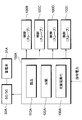
- FIG. 2 is a functional block diagram showing the control device of FIG.
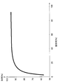
- FIG. 3 is a diagram showing the relationship between the efficiency and load factor of the converter of FIG.
- FIG. 4 is a flowchart showing the flow of processing of the control device of FIG.
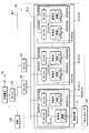
- FIG. 5 is a configuration diagram illustrating a control device according to the second embodiment and a storage battery system to which the control device is applied.
- FIG. 6 is a flowchart showing the flow of processing of the control device of FIG.
- the storage battery system 61 is configured as a system for supplying power to a load LD such as a factory or a building.
- the load LD is supplied with power from a commercial power source (not shown). Three-phase 200V AC power is supplied from the commercial power supply to the load LD via the AC bus line SL1.
- the load LD can be supplied with single-phase AC power as well as three phases.
- the storage battery system 61 is connected in the middle of the AC bus line SL1 that connects the commercial power supply and the load LD.
- the storage battery system 61 is installed for the purpose of supplying auxiliary power to the load LD via the AC bus line SL1, and suppressing the power received by the load LD from the commercial power source.
- a photovoltaic power generation unit 20 is connected to the AC bus line SL1.
- the solar power generation unit 20 is a device for converting solar energy to generate electric power and supplying the electric power to the load LD.
- the electric power generated in the photovoltaic power generation unit 20 is supplied to the load LD via the AC bus line SL1.
- the solar power generation unit 20 includes a solar cell 21 and an inverter 22.
- the solar cell 21 is a device that generates sunlight by receiving sunlight and converting the energy thereof into DC power.
- the solar cell 21 is installed outdoors.
- the inverter 22 is a power converter for converting the DC power generated by the solar cell 21 into three-phase 200V AC power and supplying the power to the AC bus line SL1.
- a set of solar cells 21 and an inverter 22 are connected to the AC bus line SL1, but not limited to this, depending on the scale of the load LD and the performance of the solar cells 21.
- the solar cell 21 and the inverter 22 may be added.
- the storage battery system 61 can temporarily charge the power that is not consumed by the load LD among the power supplied from the solar power generation unit 20 or the commercial power source. When the power consumed by the load LD is large, the storage battery system 61 can suppress the power received by the load LD from the commercial power supply by supplying the charged power to the load LD. . In addition, when the electricity charge for each time zone is introduced, the storage battery system 61 is charged by receiving power supply from a commercial power source in a time zone when the electricity rate is low, while the time when the electricity rate is high. It is also possible to supply electric power to the load LD by discharging the band.
- the power supplied from the commercial power source is suppressed by supplying power from the storage battery system 61, and the contract power with the power company is reduced.
- the electricity bill paid to the electric power company it is possible to reduce the electricity bill paid to the electric power company.
- the electric power charged by the storage battery system 61 is supplied to the load LD via the DC bus line SL2 and the AC bus line SL1.
- the DC bus line SL2 is connected to the AC bus line SL1 via the interconnection inverter 40.
- the storage battery system 61 includes five storage batteries 31 of storage batteries 31A, 31B, 31C, 31D, and 31E and five DC / DC converters 32 of DC / DC converters 32A, 32B, 32C, 32D, and 32E.
- the storage batteries 31C and 31D and the DC / DC converters 32C and 32D are not shown.
- the storage battery 31 and the DC / DC converter 32 form one set, and a total of five sets are connected in parallel to the DC bus line SL2.
- the DC / DC converters 32A, 32B, 32C, 32D, and 32E are collectively referred to as a converter 32, and the converter 32 corresponds to an example of a power converter according to the present disclosure.
- Each storage battery 31 of storage batteries 31A, 31B, 31C, 31D, and 31E is a secondary battery made of a lithium ion battery or a nickel metal hydride battery.
- the capacity of each storage battery 31 may be the same or different.
- Each DC / DC converter 32 of DC / DC converters 32A, 32B, 32C, 32D, and 32E is electrically connected to storage batteries 31A, 31B, 31C, 31D, and 31E, respectively.
- the DC / DC converter 32 is a power converter that boosts DC power discharged from the storage battery 31 and supplies the boosted DC power to the DC bus line SL2. That is, it can be said that the DC / DC converter 32 adjusts the voltage between the DC bus line SL2 and the storage battery 31 and connects the two.
- the number of the storage batteries 31 and the DC / DC converters 32 is not limited to five, and may be increased or decreased according to the capacity of the storage battery 31 or the scale of the load LD.
- the interconnection inverter 40 is a power converter that converts DC power supplied via the DC bus line SL2 into AC power and supplies the AC power to the AC bus line SL1.
- the interconnection inverter 40 can also convert AC power supplied via the AC bus line SL1 into DC power and supply it to the DC bus line SL2. In other words, the interconnection inverter 40 can supply power in both directions between the AC bus line SL1 and the DC bus line SL2.
- the control device 100 is a part of a computer system that performs integrated control of the entire storage battery system 61.
- the control device 100 includes a master control unit 100A and slave control units 100B, 100C, 100D, and 100E. In FIG. 1, illustration of the slave control units 100C and 100D is omitted.
- the master control unit 100A is a subsystem that is electrically connected to and controls the DC / DC converter 32A and slave control units 100B, 100C, 100D, and 100E.
- the master control unit 100A is electrically connected to a host controller 50, which will be described later, and can communicate with each other.
- a host controller 50 which will be described later, and can communicate with each other.
- the term “electrically connected” in the present application is not limited to the state of being connected by wire, and may include a state in which wireless communication is possible.
- the slave control units 100B, 100C, 100D, and 100E are subsystems that are electrically connected to and control the DC / DC converters 32B, 32C, 32D, and 32E, respectively.
- the master control unit 100A has a reading unit 110A, a distribution unit 120A, and a charge / discharge execution unit 130A as functional control blocks. The function of each part will be described later.
- the storage battery system 61 configured as described above performs charge / discharge based on a command received from the host controller 50.
- the host controller 50 is a device that adjusts demand power, which is power required by the load LD, and supply power, which is power supplied from the storage battery system 61 to the load LD.
- the host controller 50 is electrically connected to the interconnected inverter 40 and controls it.
- the reading unit 110A of the master control unit 100A reads the command power (hereinafter referred to as “charging”). Also referred to as “command power”).
- the distribution unit 120A of the master control unit 100A distributes power (hereinafter referred to as “distributed charging power”) that is power to be charged to each storage battery 31 in order to charge the charging command power read by the reading unit 110A. ). That is, the distributed charge power of each storage battery 31 is determined so that the sum of the distributed charge power of each storage battery 31 matches the charge command power.
- the charge / discharge execution unit 130A of the master control unit 100A causes each storage battery 31 to be charged with the distributed charge power determined by the distribution unit 120A. Specifically, the charging is performed based on a control signal transmitted from the master control unit 100A to the DC / DC converter 32A and the slave control units 100B, 100C, 100D, and 100E.
- the DC / DC converter 32A that has received the signal causes the storage battery 31A to charge the determined distributed charging power.
- the slave control units 100B, 100C, 100D, and 100E that have received the signal transmit control signals to the DC / DC converters 32B, 32C, 32D, and 32E, respectively, and are determined to be the storage batteries 31B, 31C, 31D, and 31E.
- the distributed charge power is charged. Note that when the charge command power is small, a part of the storage battery 31 has a distributed charge power of zero and may not be charged substantially.
- command power the command power
- discharge command power the command power
- the distribution unit 120A of the master control unit 100A determines the power to be discharged to each storage battery 31 (hereinafter also referred to as “distributed discharge power”) in order to discharge the discharge command power read by the reading unit 110A. . That is, the distributed discharge power of each storage battery 31 is determined so that the sum of the distributed discharge power of each storage battery 31 matches the discharge command power.
- the charge / discharge execution unit 130A of the master control unit 100A is a part that causes each storage battery 31 to discharge the distributed discharge power determined by the distribution unit 120A. As in the case of the above-described charging, the discharging is performed based on a control signal that the master control unit 100A transmits to the DC / DC converter 32A and the slave control units 100B, 100C, 100D, and 100E. In addition, when the discharge command power is small, a part of the storage battery 31 may have a distributed discharge power of zero and may not be discharged.
- the storage battery group 10 including the storage battery 31, the control device 100, and the like functions as if it were one large storage battery and can perform charging and discharging.
- FIG. 3 shows the relationship between the load factor and efficiency in the DC / DC converter 32.
- the “load factor” on the horizontal axis of the graph indicates the percentage of the power input to the DC / DC converter 32 with respect to the rated input / output of the DC / DC converter 32. Therefore, the load factor increases as the power discharged from the storage battery 31 or the power charged in the storage battery 31 via the DC bus line SL2 increases. When the load factor is 100%, charging or discharging with electric power substantially equal to the rated input / output of the DC / DC converter 32 is performed.
- the “efficiency” on the vertical axis of the graph indicates the ratio of the power output from the DC / DC converter 32 to the power input to the DC / DC converter 32 as a percentage. Therefore, when the power input to the DC / DC converter 32 is constant, the efficiency increases as the power output from the DC / DC converter 32 increases. When the efficiency is 100%, power substantially equal to the power input to the DC / DC converter 32 is output from the DC / DC converter 32.
- the DC / DC converter 32 there is a relationship in which efficiency increases as the load factor increases. Further, when the load factor is 100%, the efficiency is the highest, which is a value close to 100%. That is, the DC / DC converter 32 has a characteristic that the efficiency increases as power closer to the rated input / output is input. In other words, when the electric power input to the DC / DC converter 32 is greatly deviated from the rated input / output of the DC / DC converter 32, the efficiency is lowered and the operation efficiency of the storage battery system 61 is lowered. .
- the distribution unit 120A of the master control unit 100A determines distribution power to be charged / discharged to each storage battery 31 in consideration of such characteristics of the DC / DC converter 32. A process executed by the master control unit 100A when determining the distributed power of each storage battery 31 will be described with reference to FIG.
- the master control unit 100A reads the command power Pcmd in S101.
- the command power Pcmd is a positive value when the host controller 50 requests the storage battery group 10 to be charged, and is a negative value when the host controller 50 requests the storage battery group 10 to discharge. . That is, when the command power Pcmd is a positive value, the command power Pcmd corresponds to the above-described charge command power. When the command power Pcmd is a negative value, the command power Pcmd corresponds to the discharge command power described above.
- the master control unit 100A determines whether or not the command power Pcmd is a positive value.
- the command power Pcmd is a positive value (S102: Yes)
- the master control unit 100A charges each storage battery 31.
- the process proceeds to step S103 to determine the distribution power Pdist to be performed.
- the distributed power Pdist is the power to charge / discharge each storage battery 31.
- the distributed power Pdist corresponds to the above-described charging command power.
- the distributed power Pdist corresponds to the discharge command power described above.
- the master control unit 100A switches the target storage battery 31 so as to execute the process of determining the distributed power Pdist sequentially from the storage battery 31 having a small charging rate.
- the storage battery 31 having the smallest charging rate is selected from the storage batteries 31.
- the charging rate of the storage battery 31A is smaller than the other storage batteries 31 will be described.
- the master control unit 100A determines whether or not the command power Pcmd is larger than the rated input / output Pio of the converter 32A. When it is determined that the command power Pcmd is larger than the rated input / output Pio of the converter 32A (S104: Yes), the master control unit 100A proceeds to the process of S105.
- master control unit 100A determines whether or not chargeable power Pch of storage battery 31A is greater than rated input / output Pio of converter 32A.
- the rechargeable power Pch is zero or a positive value calculated by the following equation f1 based on the storage capacity and the charging rate of the storage battery 31A.
- the master control unit 100A determines that the distributed power Pdist of the storage battery 31A becomes the rated input / output Pio of the converter 32A. That is, the distributed power Pdist of the storage battery 31A is determined so as to increase the efficiency by operating the converter 32A with the largest load factor.
- the master control unit 100A determines whether or not the chargeable power Pch of the storage battery 31A is larger than the command power Pcmd. When it is determined that the chargeable power Pch of the storage battery 31A is not larger than the command power Pcmd (S108: No), the master control unit 100A proceeds to the process of S109.
- the master control unit 100A determines that the distributed power Pdist of the storage battery 31A is the same as the chargeable power Pch of the storage battery 31A. That is, the distributed power Pdist is determined so that the charging rate of the storage battery 31A is approximately 100%.
- the master control unit 100A After completing the process of S106 or S109, the master control unit 100A proceeds to S107. In S107, master control unit 100A calculates a value obtained by dividing distributed power Pdist of storage battery 31A from command power Pcmd, and sets this value as new command power Pcmd. After completing the process of S107, the master control unit 100A returns to the process of S102.
- the master control unit 100A determines whether or not the new command power Pcmd is a positive value.
- the command power Pcmd is a positive value (S102: Yes)
- the master control unit 100A proceeds to the process of S103.
- the master control unit 100A switches the target for executing the process of determining the distributed power Pdist from the storage battery 31A to another storage battery 31 in S103. Specifically, the master control unit 100A switches the target from the storage battery 31A to the storage battery 31 having the next lowest charging rate after the storage battery 31A.
- the master control unit 100A determines the distributed power Pdist as the rating of the converter 32 as described above. While either the input / output Pio (S106) or the chargeable power Pch (S109), the target for executing the process of determining the distributed power Pdist is sequentially switched.
- the master control unit 100A proceeds to the process of S117.
- the master control unit 100A determines that the distributed power Pdist of the storage battery 31A is the same as the command power Pcmd, and ends the process.
- the master control unit 100A switches the target storage battery 31 so as to execute processing for determining the distributed power Pdist sequentially from the storage battery 31 having a large charging rate.
- the storage battery 31 with the highest charging rate is selected from among the storage batteries 31.
- the charging rate of the storage battery 31E is larger than that of the other storage batteries 31 will be described.
- the master control unit 100A determines whether or not the command power Pcmd is smaller than a value obtained by inverting the rated input / output Pio of the converter 32A. When it is determined that the command power Pcmd is smaller than the value obtained by inverting the rated input / output Pio of the converter 32E (S111: Yes), the master control unit 100A proceeds to the process of S112.
- the master control unit 100A determines whether or not the dischargeable power Pdch of the storage battery 31E is larger than the rated input / output Pio of the converter 32E.
- the dischargeable power Pdch is zero or a positive value calculated by the following equation f2 based on the charging rate, the storage capacity, and the minimum storage remaining amount of each storage battery 31.
- each storage battery 31 is set to discharge without securing the minimum remaining amount of charge, without discharging until the remaining amount of charge becomes zero. This is because, if each storage battery 31 is discharged until the remaining amount of stored electricity becomes zero, there is a risk of causing problems such as a decrease in performance of each storage battery 31 and a shortened life.
- the master control unit 100A determines that the distributed power Pdist of the storage battery 31E is a value obtained by inverting the rated input / output Pio of the converter 32E. That is, the distributed power Pdist of the storage battery 31E is determined so as to increase the efficiency by operating the converter 32E with the largest load factor.
- the master control unit 100A determines whether or not the dischargeable power Pdch of the storage battery 31E is larger than the value obtained by reversing the command power Pcmd. When it is determined that the dischargeable power Pdch of the storage battery 31E is not greater than the value obtained by inverting the command power Pcmd (S115: No), the master control unit 100A proceeds to the process of S116.
- the master control unit 100A determines that the distributed power Pdist of the storage battery 31E is the same as the value obtained by reversing the dischargeable power Pdch of the storage battery 31E. That is, the distribution power Pdist is determined so that the remaining amount of electricity stored in the storage battery 31E becomes the above-described minimum remaining amount of electricity.
- step S114 the master control unit 100A calculates a value obtained by dividing the command power Pcmd by the distribution power Pdist of the storage battery 31E, and sets the value as the new command power Pcmd. After completing the process in S114, the master control unit 100A returns to the process in S102.
- the master control unit 100A determines whether or not the new command power Pcmd is a positive value.
- the master control unit 100A proceeds to the process of S110.
- the master control unit 100A switches the target for executing the process of determining the distributed power Pdist from the storage battery 31E to another storage battery 31 in S110. Specifically, the master control unit 100A switches the target from the storage battery 31E to the storage battery 31 having the next highest charging rate after the storage battery 31E.
- the master control unit 100A distributes the power as described above.
- a target for executing the process of determining the distributed power Pdist while either Pdist is a value obtained by inverting the rated input / output Pio of the converter 32 (S113) or a value obtained by inverting the dischargeable power Pdch (S116). Switch sequentially.
- the master control unit 100A determines that the distributed power Pdist of the storage battery 31E is the same as the command power Pcmd, and ends the process.
- the distributed power Pdist is determined in order from the storage battery 31 having the smallest charging rate among the plurality of storage batteries 31. Further, storage battery 31 having chargeable power Pch larger than rated input / output Pio of converter 32 is determined so that distributed power Pdist is substantially the same as rated input / output Pio. Therefore, when the storage battery group 10 is required to be charged, the storage battery 31 having a small charging rate is controlled so as to charge the distribution power Pdist substantially the same as the rated input / output Pio of the converter 32. Can be done.
- the distributed power Pdist is determined in order from the storage battery 31 having the largest charging rate among the plurality of storage batteries 31. Further, storage battery 31 having dischargeable power Pdch larger than rated input / output Pio of converter 32 is determined such that distributed power Pdist is substantially the same as rated input / output Pio. Therefore, when the storage battery group 10 is required to be discharged, the storage battery 31 having a large charging rate is controlled to discharge the distribution power Pdch that is substantially the same as the rated input / output Pio of the converter 32. It becomes possible.
- the distribution power Pdist is determined from the storage battery 31 having a small or large charge rate, thereby improving the usage rate of the storage battery 31 constituting the storage battery group 10 and converting the distribution power Pdist to the converter 32.
- the rated input / output Pio substantially the same, high efficiency can be achieved.
- the dischargeable power Pdch of the storage battery 31 is set to an amount obtained by dividing the minimum charge remaining amount from the power charged by the storage battery 31.
- control device 100 determines in S106 that the distributed power Pdist of the storage battery 31 is the same as the rated input / output Pio of the converter 32.
- the present disclosure does not require that the distributed power Pdist be completely the same as the rated input / output Pio. That is, as long as the improvement in charging efficiency is recognized to the same extent as when the distributed power Pdist is completely the same as the rated input / output Pio, both need only be in substantially the same range including the completely same.
- the disclosure of the present disclosure Included in the range.
- control device 200 according to the second embodiment of the present disclosure will be described with reference to FIGS. 5 and 6. Note that, in the second embodiment, portions common to the first embodiment described above are denoted by common reference numerals, and description thereof is omitted as appropriate.
- the control device 200 according to the second embodiment is different from the control device 100 according to the first embodiment described above in that the control target is the storage battery system 62 and the processing specialized for the storage battery system 62 can be executed.
- the plurality of storage batteries 31 and the DC / DC converter 32 included in the storage battery system 62 constitute a plurality of clusters CL.
- the plurality of clusters CL includes clusters CL1, CL2, CL3, CL4, and CL5. In FIG. 5, illustration of the clusters CL3 and CL4 is omitted.
- Each cluster CL has five sets of storage batteries 31 and a DC / DC converter 32. In FIG. 5, a part of the storage battery 31 and the DC / DC converter 32 included in each cluster CL is omitted. Each cluster CL is connected in parallel to the DC bus line SL2.
- the control device 200 is a part of a computer system that performs integrated control of the entire storage battery system 62.
- the cluster CL1 includes a master control unit 201A and slave control units 201B, 201C, 201D, and 201E.
- the control devices 200 provided in each of the clusters CL2, CL3, CL4, and CL5 are all slave control units controlled by the master control unit 201A.
- the master control unit 201A is a subsystem that is electrically connected to and controls the DC / DC converter 321A and the slave control unit that is the other part of the control device 200.
- the master control unit 201A is electrically connected to the host controller 50 and can communicate with each other.
- the master control unit 201A has the same functions as the reading unit 110A, the distribution unit 120A, and the charge / discharge execution unit 130A of the master control unit 100A described above.
- the storage battery group 11 having a plurality of clusters CL can function as if it were one large storage battery and charge and discharge.
- the master control unit 201A has a function of managing charging / discharging of each storage battery 31 in units of clusters CL. A process executed by the master control unit 201A when determining the distribution power of each storage battery 31 will be described with reference to FIG.
- the master control unit 201A reads the command power Pcmd in S201.
- the master control unit 201A determines whether or not the command power Pcmd is a positive value.
- the command power Pcmd is a positive value (S202: Yes)
- the master control unit 201A charges each storage battery 31.
- the process proceeds to S203 to determine the distributed power Pdist to be performed.
- the master control unit 201A executes the processing after S203 for each cluster CL in accordance with a predetermined order for charging.
- the order is determined in advance so that the process is first executed for cluster CL1, second for cluster CL2, third for cluster CL3, fourth for cluster CL4, and finally for cluster CL5. The case will be described.
- the master control unit 201A determines whether or not the charging rate of all the storage batteries 31 in the cluster CL1 is 100%. If there is even one storage battery 31 having a charging rate of less than 100% in the cluster CL1 (S203: No), the master control unit 201A proceeds to the process of S204.
- the master control unit 201A switches the target storage battery 31 so as to execute the process of determining the distributed power Pdist sequentially from the storage battery 31 having a small charging rate in the cluster CL1.
- the storage battery 31 with the smallest charging rate is selected from the storage batteries 31 in the cluster CL1.
- the charging rate of the storage battery 311A is smaller than the other storage batteries 31 in the cluster CL1 will be described.
- the master control unit 201A appropriately executes the processing shown in S205 to S210 for the storage battery 311A. Since the processing shown in S205 to S210 is the same as the processing shown in S104 to S109 of FIG. 4 described above, description thereof is omitted here.
- the master control unit 201A that has calculated the new command power Pcmd in S208 returns to the process of S202. If it is determined in S202 that the new command power Pcmd is a positive value (S202: Yes), the master control unit 201A proceeds to the process of S203.
- the master control unit 201A determines whether or not the charging rate of all the storage batteries 31 in the cluster CL1 is 100%. That is, it is determined whether or not the charging rate of all the storage batteries 31 in the cluster CL1 is 100% by charging the distribution power Pdist determined in the previous cycle. Even when charging of the distributed power Pdist determined in the previous cycle is performed, when there is even one storage battery 31 having a charging rate of less than 100% in the cluster CL1 (S203: No), the master control unit 201A Advances to the process of S204.
- the master control unit 201A switches the target for executing the process of determining the distributed power Pdist from the storage battery 311A to the other storage battery 31 in the cluster CL1. Specifically, the master control unit 201A switches the target from the storage battery 311A to the storage battery 31 having the second lowest charge rate after the storage battery 311A.
- the master control unit 201A switches the target for executing the processing after S204 from the cluster CL1 to another cluster CL. Specifically, the master control unit 201A switches the target from the cluster CL1 to the second cluster CL2 in a predetermined order.
- the master control unit 201A sequentially switches the cluster CL to be processed, The distribution power Pdist of each storage battery 31 is determined.
- the master control unit 201A performs the processing from S212 onward for each cluster CL in accordance with a predetermined order for discharging.
- the order is determined in advance so that the process is first executed for cluster CL5, second for cluster CL4, third for cluster CL3, fourth for cluster CL2, and finally for cluster CL1. The case will be described.
- the master control unit 201A determines whether or not the charging rates of all the storage batteries 31 in the cluster CL5 are the minimum charging rate. When there is even one storage battery 31 whose charge rate is not the minimum charge rate MinSOC in the cluster CL5 (S212: No), the master control unit 201A proceeds to the process of S213.
- the master control unit 201A switches the target storage battery 31 so as to execute processing for determining the distributed power Pdist sequentially from the storage battery 31 having a large charging rate in the cluster CL5.
- the storage battery 31 with the highest charging rate is selected from among the storage batteries 31.
- the charging rate of the storage battery 315E is larger than that of the other storage batteries 31 in the cluster CL5 will be described.
- the master control unit 201A appropriately executes the processes shown in S214 to S219 for the storage battery 315E. Since the processes shown in S214 to S219 are the same as the processes shown in S111 to S116 of FIG. 4 described above, the description thereof is omitted here.
- the master control unit 201A that has calculated the new command power Pcmd in S217 returns to the process of S202. If it is determined in S202 that the new command power Pcmd is not a positive value (S202: No), the master control unit 201A proceeds to the process of S212.
- the master control unit 201A determines whether or not the charging rate of all the storage batteries 31 in the cluster CL5 is the minimum charging rate MinSOC. That is, it is determined whether or not the charge rate of all the storage batteries 31 in the cluster CL5 becomes the minimum charge rate MinSOC by discharging the distributed power Pdist determined in the previous cycle. Even if the distributed power Pdist determined in the previous cycle is discharged, there is at least one storage battery 31 whose charge rate does not become the minimum charge rate MinSOC in the cluster CL5 (S212: No), the master control unit 201A proceeds to the process of S213.
- the master control unit 201A switches the target for executing the process of determining the distributed power Pdist from the storage battery 315E to another storage battery 31 in the cluster CL5. Specifically, the master control unit 201A switches the target from the storage battery 315E to the storage battery 31 having the next highest charging rate after the storage battery 315E.
- the master control unit 201A discharges the distributed power Pdist determined in the previous cycle, there is at least one storage battery 31 whose charge rate is not the minimum charge rate MinSOC in the cluster CL5 (S212). : No), and when the new command power Pcmd is smaller than the value obtained by inverting the rated input / output Pio of the converter 32 of the target storage battery 31 (S214: Yes), the distributed power Pdist is rated for the converter 32.
- the target for executing the process of determining the distribution power Pdist is sequentially performed in the cluster CL5 while either the value obtained by inverting the input / output Pio (S216) or the value obtained by inverting the dischargeable power Pdch (S219). Switch.
- the master control unit 201A switches the target for executing the processing after S213 from the cluster CL5 to another cluster CL. Specifically, the master control unit 201A switches the target from the cluster CL5 to the second cluster CL4 in a predetermined order.
- the master control unit 201A sequentially switches the cluster CL to be processed. Then, the distributed power Pdist of each storage battery 31 is determined.
- the control device 200 when the control device 200 reads the command power Pcmd requesting charging, the control device 200 determines the distributed power Pdist of the storage battery 31 for each cluster CL according to a predetermined order. In addition, when the charging rate of the storage battery 31 of one cluster CL increases to 100% due to charging, the control device 200 determines the distribution power Pdist of the storage battery 31 of another cluster CL.
- the control device 200 determines the distributed power Pdist of the storage battery 31 for each cluster CL according to a predetermined order. In addition, when the charging rate of the storage battery 31 of one cluster CL drops to the minimum charging rate MinSOC due to the discharge, the control device 200 determines the distribution power Pdist of the storage battery 31 of the other cluster CL.
- the distributed power Pdist is substantially the same as the rated input / output Pio of the converter 32 while improving the usage rate of the storage battery 31. By doing so, it becomes possible to exhibit high efficiency.
- a control device converts power discharged from a plurality of storage batteries constituting a storage battery group by a power converter and supplies the power to a load, and converts power supplied from the outside to the storage battery group by a power converter. And it is a control apparatus of the storage battery system which charges a some storage battery.
- the control device reads the charging command power and the discharging command power for the storage battery group, determines the distributed charging power that is the power to be charged to each of the plurality of storage batteries based on the charging command power, and based on the discharging command power
- the distribution unit that determines the distributed discharge power that is the power to be discharged to each of the plurality of storage batteries, and the charge / discharge execution that charges or discharges the plurality of storage batteries based on the distributed charge power or the distributed discharge power determined by the distribution unit A section.
- the reading unit reads the charging command power
- the distributing unit determines the distributed charging power in order from the storage battery having the smallest charging rate among the plurality of storage batteries, and the chargeable power is the rated input of the power converter.
- the storage battery larger than the output is determined so that the distributed charging power is substantially the same as the rated input / output.
- the distribution unit determines the distributed discharge power in order from the storage battery having the highest charging rate among the plurality of storage batteries, and the dischargeable power is a power converter.
- a storage battery larger than the rated input / output is determined so that the distributed discharge power is substantially the same as the rated input / output.
- the distributed charging power is determined in order from the storage battery having the smallest charging rate among the plurality of storage batteries. Furthermore, the storage battery whose chargeable power is larger than the rated input / output of the power converter is determined such that the distributed charging power is substantially the same as the rated input / output. Therefore, when the storage battery group is required to be charged, charging is performed with high efficiency in order to control the storage battery having a small charging rate to be charged with the same distributed charging power as the rated input / output of the power converter. Is possible.
- the distributed discharge power is determined in order from the storage battery having the highest charging rate among the plurality of storage batteries. Furthermore, the storage battery whose dischargeable power is larger than the rated input / output of the power converter is determined so that the distributed discharge power is substantially the same as the rated input / output. Therefore, when the storage battery group is required to discharge, control is performed so that the storage battery with a large charging rate discharges the distributed discharge power substantially the same as the rated input / output of the power converter. Is possible.
- the distributed charging power can be improved while the usage rate of the storage batteries constituting the storage battery group is improved by determining the distributed charging power or the distributed discharging power from the storage batteries having a small or large charging rate. And by making the distributed discharge power substantially the same as the rated input / output of the power converter, it becomes possible to exhibit high efficiency.
- the distributed charge power and the distributed discharge power are set to be “substantially the same” as the rated input / output of the power converter. It does not mean to eliminate. In order to maximize the charging / discharging efficiency of the storage battery, it is preferable to make the both completely the same.
- the gist of the present disclosure is not limited to this, and an improvement in charge / discharge efficiency is recognized to the same extent as when the distributed charge power and the distributed discharge power are completely the same as the rated input / output of the power converter. As long as they are within the same range including the completely same.
- the increase in charge / discharge efficiency is recognized to the same extent as in the case where there is no difference. If included, they are encompassed within the scope of the present disclosure.
- control device of the present disclosure it is possible to provide a control device for a storage battery system that can exhibit high efficiency while improving the usage rate of the storage batteries constituting the storage battery group.
- each step is expressed as, for example, S101. Further, each step can be divided into a plurality of sub-steps, while a plurality of steps can be combined into one step.
Landscapes
- Engineering & Computer Science (AREA)
- Power Engineering (AREA)
- Charge And Discharge Circuits For Batteries Or The Like (AREA)
- Supply And Distribution Of Alternating Current (AREA)
Abstract
電力を負荷に供給するとともに、複数の蓄電池を充電する蓄電池システムの制御装置が提供される。制御装置は、充電指令電力及び放電指令電力を読み込む読込部と、分配充電電力と分配放電電力を決定する分配部と、複数の蓄電池を充電又は放電させる充放電実行部と、を備える。分配部は、読込部が充電指令電力を読み込んだ場合は、充電可能な電力が電力変換器の定格入出力よりも大きい蓄電池は、分配充電電力が該定格入出力と略同一となるように決定する。分配部は、読込部が放電指令電力を読み込んだ場合は、放電可能な電力が電力変換器の定格入出力よりも大きい蓄電池は、分配放電電力が該定格入出力と略同一となるように決定する。
Description
本出願は、2015年3月24日に出願された日本国特許出願2015-61537号に基づくものであり、その開示をここに参照により援用する。
本開示は、蓄電池群を構成する複数の蓄電池が放電した電力を電力変換器によって変換して負荷に供給するとともに、外部から蓄電池群に供給される電力を電力変換器によって変換して複数の蓄電池を充電する蓄電池システムの制御装置に関する。
例えば下記特許文献1には、複数の蓄電池を備えた蓄電池システムが開示されている。各蓄電池には、リチウムイオン電池等の二次電池が採用されている。各蓄電池が放電する直流電力は、DC/DCコンバータによって変換されて昇圧された後、更にDC/ACインバータによって交流電力に変換され、負荷に供給される。また、外部から蓄電池システムに供給される電力は、DC/DCコンバータによって変換されて降圧された後に、各蓄電池に充電される。
また、各蓄電池における充放電は、蓄電池ごとに設けられる制御部によって制御される。そして、当該制御部は、上位コントローラからの指令に基づいて制御を行う。上位コントローラは、負荷が要求する電力である需要電力と、蓄電池システムから当該負荷に供給する電力である供給電力と、の調整を行う機器である。各制御部は、各蓄電池が充放電する電力の総和が、上位コントローラからの指令電力と一致するように制御する。すなわち、上位コントローラからみれば、複数の蓄電池からなる蓄電池群は、あたかも一つの大きな蓄電池として機能する。
各蓄電池の充電率は、一様になるとは限らない。したがって、蓄電池システムが放電する場合は、充電率が大きい蓄電池から優先的に放電させる一方で、蓄電池システムが充電する場合は、充電率が小さい蓄電池から優先的に充電させることが一般的に行われている。これにより、上位コントローラからの指令電力に対応する充放電を確実に行うことが可能としている。
蓄電池システムにおいてこのような充放電を行うと、蓄電池ごとに使用率にばらつきが生じるおそれがある。すなわち、複数の蓄電池のうち、特定の蓄電池のみが充放電を頻繁に行う一方で、他の蓄電池はほとんど充放電を行わないおそれがある。この場合、当該特定の蓄電池の劣化が、他の蓄電池に比べて著しく進行するおそれがある。
DC/DCコンバータは、定格入出力と大きく異なる動作点で動作させると、その効率が著しく低下するという特性がある。すなわち、各蓄電池において充放電を行う際の電気エネルギーの損失が大きくなり、蓄電池システムとしての効率の低下を招くおそれがある。
蓄電池群において特定の蓄電池の劣化の進行を抑制しつつ、高い効率を発揮させるように蓄電池システムを制御する制御装置が待望されていることを本願発明者は見出した。
本開示は、蓄電池群を構成する蓄電池の使用率を向上させながらも、高い効率を発揮させることが可能な蓄電池システムの制御装置を提供することを目的とする。
本開示の一例による制御装置は、蓄電池群を構成する複数の蓄電池が放電した電力を電力変換器によって変換して負荷に供給するとともに、外部から前記蓄電池群に供給される電力を前記電力変換器によって変換して前記複数の蓄電池を充電する蓄電池システムの制御装置である。制御装置は、前記蓄電池群に対する充電指令電力及び放電指令電力を読み込む読込部と、前記充電指令電力に基づいて前記複数の蓄電池のそれぞれに充電させる電力である分配充電電力を決定するとともに、前記放電指令電力に基づいて前記複数の蓄電池のそれぞれに放電させる電力である分配放電電力を決定する分配部と、前記分配部によって決定された前記分配充電電力又は前記分配放電電力に基づいて、前記複数の蓄電池を充電又は放電させる充放電実行部と、を備える。前記分配部は、前記読込部が前記充電指令電力を読み込んだ場合は、前記複数の蓄電池のうち充電率が小さい前記蓄電池から順に前記分配充電電力を決定するものであって、充電可能な電力が前記電力変換器の定格入出力よりも大きい前記蓄電池は、前記分配充電電力が該定格入出力と略同一となるように決定する。一方で、分配部は、前記読込部が前記放電指令電力を読み込んだ場合は、前記複数の蓄電池のうち充電率が大きい前記蓄電池から順に前記分配放電電力を決定するものであって、放電可能な電力が前記電力変換器の定格入出力よりも大きい前記蓄電池は、前記分配放電電力が該定格入出力と略同一となるように決定する。
本開示の制御装置によれば、読込部が充電指令電力を読み込んだ場合は、複数の蓄電池のうち充電率が小さい蓄電池から順に分配充電電力を決定する。さらに、充電可能な電力が電力変換器の定格入出力よりも大きい蓄電池は、分配充電電力が定格入出力と略同一となるように決定する。したがって、蓄電池群が充電を求められている場合は、充電率が小さい蓄電池から電力変換器の定格入出力と略同一の分配充電電力を充電させるように制御するため、高い効率で充電を行うことが可能となる。
本開示の制御装置によれば、読込部が放電指令電力を読み込んだ場合は、複数の蓄電池のうち充電率が大きい蓄電池から順に分配放電電力を決定する。さらに、放電可能な電力が電力変換器の定格入出力よりも大きい蓄電池は、分配放電電力が定格入出力と略同一となるように決定する。したがって、蓄電池群が放電を求められている場合は、充電率が大きい蓄電池から電力変換器の定格入出力と略同一の分配放電電力を放電させるように制御するため、高い効率で放電を行うことが可能となる。
本開示の制御装置によれば、充電率が小さい又は大きい蓄電池から分配充電電力又は分配放電電力を決定することで、蓄電池群を構成する蓄電池の使用率を向上させながらも、分配充電電力及び分配放電電力を電力変換器の定格入出力と略同一とすることで、高い効率を発揮させることが可能となる。
本開示の制御装置によれば、蓄電池群を構成する蓄電池の使用率を向上させながらも、高い効率を発揮させることが可能な蓄電池システムの制御装置を提供することができる。
本開示についての上記および他の目的、特徴や利点は、添付の図面を参照した下記の詳細な説明から、より明確になる。添付図面において、
図1は、第1実施形態に係る制御装置及び当該制御装置が適用される蓄電池システムを示す構成図であり、
図2は、図1の制御装置を示す機能ブロック図であり、
図3は、図1のコンバータの効率と負荷率との関係を示す図であり、
図4は、図1の制御装置の処理の流れを示すフローチャートであり、
図5は、第2実施形態に係る制御装置及び当該制御装置が適用される蓄電池システムを示す構成図であり、
図6は、図5の制御装置の処理の流れを示すフローチャートである。
以下、添付図面を参照しながら本開示の実施形態について説明する。説明の理解を容易にするため、各図面において同一の構成要素に対しては可能な限り同一の符号を付して、重複する説明は省略する。
まず、図1を参照しながら、本開示の第1実施形態に係る制御装置100の制御対象である蓄電池システム61について説明する。蓄電池システム61は、工場やビル等の負荷LDに電力を供給するためのシステムとして構成されている。
尚、負荷LDは、商用電源(不図示)から電力の供給を受けている。負荷LDには、交流バスラインSL1を介して、商用電源から3相200Vの交流電力が供給されている。尚、負荷LDは、3相のみならず単相の交流電力の供給を受けることも可能である。
蓄電池システム61は、この商用電源と負荷LDとを繋ぐ交流バスラインSL1の途中に接続されている。蓄電池システム61は、交流バスラインSL1を介して補助的な電力を負荷LDに供給し、負荷LDが商用電源から供給を受ける電力を抑制することを目的として設置される。交流バスラインSL1には、この他にも太陽光発電ユニット20が接続されている。
太陽光発電ユニット20は、太陽光エネルギーを変換して電力を発生させ、当該電力を負荷LDに供給するための装置である。太陽光発電ユニット20において発生した電力は、交流バスラインSL1を介して負荷LDに供給される。
太陽光発電ユニット20は、太陽電池21と、インバータ22とを備えている。太陽電池21は、太陽光を受光し、そのエネルギーを直流電力に変換することによって電力を発生させる機器である。太陽電池21は、屋外に設置されている。
インバータ22は、太陽電池21で発生させた直流電力を3相200Vの交流電力に変換し、当該電力を交流バスラインSL1に供給するための電力変換器である。図1に示されるように、本実施形態では1組の太陽電池21及びインバータ22が交流バスラインSL1に接続されているが、これに限らず、負荷LDの規模や太陽電池21の性能に応じて、太陽電池21及びインバータ22を増設してもよい。
晴天時の昼間においては、太陽光発電ユニット20から負荷LDに電力が供給される。これにより、負荷LDが商用電源から供給を受ける電力が抑制され、電力事業者に支払う電気料金を低減させることができる。
蓄電池システム61は、太陽光発電ユニット20又は商用電源から供給された電力のうち、負荷LDで消費されなかった電力を一時的に充電可能である。負荷LDが消費する電力が大きい場合は、蓄電池システム61は、充電している電力を負荷LDに供給することで、負荷LDが商用電源から供給を受ける電力を抑制することが可能となっている。また、蓄電池システム61は、時間帯別の電気料金を導入している場合には、電気料金が低額な時間帯に商用電源から電力の供給を受けて充電する一方で、電気料金が高額な時間帯に放電して負荷LDに電力を供給することも可能である。さらに、負荷LDにおける電力消費量が最大に達する時間帯において、蓄電池システム61から電力を供給することで負荷LDが商用電源から供給を受ける電力を抑制し、電力事業者との契約電力を小さくして、電力事業者に支払う電気料金を低減させることも可能となる。
蓄電池システム61が充電している電力は、直流バスラインSL2及び交流バスラインSL1を介して負荷LDに供給される。直流バスラインSL2は、連系インバータ40を介して交流バスラインSL1に接続されている。
蓄電池システム61は、蓄電池31A,31B,31C,31D,31Eの5つの蓄電池31と、DC/DCコンバータ32A,32B,32C,32D,32Eの5つのDC/DCコンバータ32とを備えている。図1では、蓄電池31C,31D及びDC/DCコンバータ32C,32Dの図示を省略している。蓄電池システム61は、蓄電池31とDC/DCコンバータ32とが1つずつ組となり、計5組が直流バスラインSL2に対して並列に接続されている。DC/DCコンバータ32A,32B,32C,32D,32Eを総称してコンバータ32とも呼び、コンバータ32は本開示の電力変換器の一例に相当する。
蓄電池31A,31B,31C,31D,31Eの各蓄電池31は、リチウムイオン電池又はニッケル水素電池からなる二次電池である。各蓄電池31の容量はすべて同一であってもよいし、異なるものであってもよい。
DC/DCコンバータ32A,32B,32C,32D,32Eの各DC/DCコンバータ32は、それぞれ蓄電池31A,31B,31C,31D,31E,と電気的に接続されている。DC/DCコンバータ32は、蓄電池31から放電された直流電力を昇圧して直流バスラインSL2に供給する電力変換器である。つまり、DC/DCコンバータ32は、直流バスラインSL2と蓄電池31との間で電圧を調整して両者を繋ぐものということができる。
尚、蓄電池31及びDC/DCコンバータ32の数は5組に限られず、蓄電池31の容量や、負荷LDの規模に応じて増減してもよい。
連系インバータ40は、直流バスラインSL2を介して供給される直流電力を交流電力に変換し、交流バスラインSL1に供給する電力変換器である。また、連系インバータ40は、交流バスラインSL1を介して供給される交流電力を直流電力に変換し、直流バスラインSL2に供給することもできる。つまり、連系インバータ40により、交流バスラインSL1と直流バスラインSL2との間で、双方向に電力の供給を行うことが可能とされている。
続いて、制御装置100について説明する。制御装置100は、蓄電池システム61の全体の統合制御を行うコンピュータシステムの一部である。制御装置100は、マスター制御部100Aと、スレーブ制御部100B,100C,100D,100Eとを備えている。図1では、スレーブ制御部100C,100Dの図示を省略している。
マスター制御部100Aは、DC/DCコンバータ32A、スレーブ制御部100B,100C,100D,100Eと電気的に接続され、それらの制御を行うサブシステムである。また、マスター制御部100Aは、後述する上位コントローラ50と電気的に接続され、相互に通信可能とされている。尚、本願における「電気的に接続」とは、有線によって接続された状態に限定される意味ではなく、無線により互いに通信可能とされた状態をも含みうるものとする。
スレーブ制御部100B,100C,100D,100Eは、それぞれDC/DCコンバータ32B,32C,32D,32Eと電気的に接続され、それらの制御を行うサブシステムである。
図2に示されるように、マスター制御部100Aは、機能的な制御ブロックとして、読込部110Aと、分配部120Aと、充放電実行部130Aと、を有している。各部の機能については後述する。
以上のように構成された蓄電池システム61は、上位コントローラ50から受信する指令に基づいて充放電を行う。上位コントローラ50は、負荷LDが要求する電力である需要電力と、蓄電池システム61から負荷LDに供給する電力である供給電力と、の調整を行う機器である。また、上位コントローラ50は、連系インバータ40と電気的に接続されており、その制御を行う。
マスター制御部100Aが上位コントローラ50から受信した指令が、蓄電池システム61に対して充電を要求するものであったとき、マスター制御部100Aの読込部110Aは、その指令電力(以下、これを「充電指令電力」とも称する)を読み込む。
この場合、マスター制御部100Aの分配部120Aは、読込部110Aが読み込んだ充電指令電力を充電すべく、各蓄電池31に充電させる電力である分配電力(以下、これを「分配充電電力」とも称する)を決定する。すなわち、各蓄電池31の分配充電電力の総和が充電指令電力と一致するように、各蓄電池31の分配充電電力を決定する。
マスター制御部100Aの充放電実行部130Aは、分配部120Aで決定された分配充電電力の充電を各蓄電池31に行わせる。具体的には、当該充電は、マスター制御部100AがDC/DCコンバータ32A及びスレーブ制御部100B,100C,100D,100Eに送信する制御信号に基づいて行われる。当該信号を受信したDC/DCコンバータ32Aは、蓄電池31Aに決定された分配充電電力の充電を行わせる。また、当該信号を受信したスレーブ制御部100B,100C,100D,100Eは、それぞれDC/DCコンバータ32B,32C,32D,32Eに制御信号を送信するとともに、蓄電池31B,31C,31D,31Eに決定された分配充電電力の充電を行わせる。尚、充電指令電力が小さい場合、蓄電池31の一部は分配充電電力がゼロとなり、実質的に充電を行わない場合も生じ得る。
一方、マスター制御部100Aが上位コントローラ50から受信した指令が、蓄電池システム61に対して放電を要求するものであったとき、マスター制御部100Aの読込部110Aは、その指令電力(以下、これを「放電指令電力」とも称する)を読み込む。
この場合、マスター制御部100Aの分配部120Aは、読込部110Aが読み込んだ放電指令電力を放電すべく、各蓄電池31に放電させる電力(以下、これを「分配放電電力」とも称する)を決定する。すなわち、各蓄電池31の分配放電電力の総和が放電指令電力と一致するように、各蓄電池31の分配放電電力を決定する。
マスター制御部100Aの充放電実行部130Aは、分配部120Aで決定された分配放電電力の放電を各蓄電池31に行わせる部分である。前述した充電の場合と同様に、当該放電は、マスター制御部100AがDC/DCコンバータ32A及びスレーブ制御部100B,100C,100D,100Eに送信する制御信号に基づいて行われる。尚、放電指令電力が小さい場合、蓄電池31の一部は分配放電電力がゼロとなり、放電を行わない場合も生じ得る。
このように、上位コントローラ50側からみると、蓄電池31、制御装置100等から構成される蓄電池群10は、あたかも一つの大きな蓄電池のように機能して充放電を行い得るものである。
ここで、DC/DCコンバータ32の運転効率について、図3を参照しながら説明する。図3には、DC/DCコンバータ32における負荷率と効率との関係が示されている。
グラフ横軸の「負荷率」とは、DC/DCコンバータ32の定格入出力に対する、DC/DCコンバータ32に入力される電力の比率を百分率で示したものである。したがって、蓄電池31から放電される電力、又は、直流バスラインSL2を介して蓄電池31に充電される電力が大きいほど、負荷率が大きくなる関係にある。負荷率が100%の場合、DC/DCコンバータ32の定格入出力に略等しい電力の充電又は放電が行われる。
グラフ縦軸の「効率」とは、DC/DCコンバータ32に入力される電力に対する、DC/DCコンバータ32から出力される電力の比率を百分率で示したものである。したがって、DC/DCコンバータ32に入力される電力が一定である場合には、DC/DCコンバータ32から出力される電力が大きいほど、効率が高くなる関係にある。効率が100%の場合は、DC/DCコンバータ32に入力される電力と略等しい電力が、DC/DCコンバータ32から出力される。
図3に示されるように、DC/DCコンバータ32では、負荷率が大きいほど効率が高くなる関係がある。また、負荷率が100%のときには効率が最も高く、100%に近い値となる。つまり、DC/DCコンバータ32は、その定格入出力に近い電力を入力するほど効率が高まる特性を有している。換言すると、DC/DCコンバータ32に入力される電力が、DC/DCコンバータ32の定格入出力から大きく外れたものになると、効率が低下し、蓄電池システム61としての運転効率の低下を招いてしまう。
そこで、マスター制御部100Aの分配部120Aは、このようなDC/DCコンバータ32の特性を考慮して、各蓄電池31に充放電させる分配電力を決定している。図4を参照しながら、各蓄電池31の分配電力を決定する際にマスター制御部100Aが実行する処理について説明する。
マスター制御部100Aは、S101で、指令電力Pcmdを読み込む。指令電力Pcmdは、上位コントローラ50から蓄電池群10に対して充電を要求している場合は正となり、上位コントローラ50から蓄電池群10に対して放電を要求している場合は負となる値である。すなわち、指令電力Pcmdが正の値である場合は、当該指令電力Pcmdは前述した充電指令電力に相当する。また、指令電力Pcmdが負の値である場合は、当該指令電力Pcmdは前述した放電指令電力に相当する。
次に、マスター制御部100Aは、S102で、指令電力Pcmdが正の値であるか否かを判定する。指令電力Pcmdが正の値であると判定した場合(S102:Yes)、すなわち、上位コントローラ50が蓄電池群10に対して充電を要求している場合、マスター制御部100Aは、各蓄電池31に充電させる分配電力Pdistを決定すべく、ステップS103の処理に進む。
ここで、分配電力Pdistは、各蓄電池31に充放電させる電力である。分配電力Pdistが正の値である場合は、当該分配電力Pdistは前述した充電指令電力に相当する。また、分配電力Pdistが負の値である場合は、当該分配電力Pdistは前述した放電指令電力に相当する。
次に、マスター制御部100Aは、S103で、充電率が小さい蓄電池31から順次、分配電力Pdistを決定する処理を実行するように、対象となる蓄電池31の切り替えを行う。初回のS103の処理では、各蓄電池31のうち最も充電率が小さい蓄電池31が選択される。ここでは例として、蓄電池31Aの充電率が他の蓄電池31と比べて小さい場合について説明する。
次に、マスター制御部100Aは、S104で、指令電力Pcmdがコンバータ32Aの定格入出力Pioよりも大きいか否かを判定する。指令電力Pcmdがコンバータ32Aの定格入出力Pioよりも大きいと判定した場合(S104:Yes)、マスター制御部100Aは、S105の処理に進む。
次に、マスター制御部100Aは、S105で、蓄電池31Aの充電可能電力Pchが、コンバータ32Aの定格入出力Pioよりも大きいか否かを判定する。ここで、充電可能電力Pchは、蓄電池31Aの蓄電容量及び充電率に基づいて、次式f1によって算出されるゼロ又は正の値である。
(数1)
充電可能電力P_ch=蓄電池容量-充電率/100*蓄電池容量 …(式f1)
S105で、蓄電池31Aの充電可能電力Pchが、コンバータ32Aの定格入出力Pioよりも大きいと判定した場合(S105:Yes)、マスター制御部100Aは、S106の処理に進む。
充電可能電力P_ch=蓄電池容量-充電率/100*蓄電池容量 …(式f1)
S105で、蓄電池31Aの充電可能電力Pchが、コンバータ32Aの定格入出力Pioよりも大きいと判定した場合(S105:Yes)、マスター制御部100Aは、S106の処理に進む。
次に、マスター制御部100Aは、S106で、蓄電池31Aの分配電力Pdistが、コンバータ32Aの定格入出力Pioとなるように決定する。すなわち、コンバータ32Aを最も大きな負荷率で運転させて効率を高めるように、蓄電池31Aの分配電力Pdistを決定する。
一方、S105で、蓄電池31Aの充電可能電力Pchが、コンバータ32Aの定格入出力Pioよりも大きくないと判定した場合(S105:No)、マスター制御部100Aは、S109の処理に進む。
また、S104で、指令電力Pcmdがコンバータ32Aの定格入出力Pioよりも大きくないと判定した場合(S104:No)、マスター制御部100Aは、S108の処理に進む。
次に、マスター制御部100Aは、S108で、蓄電池31Aの充電可能電力Pchが、指令電力Pcmdよりも大きいか否かを判定する。蓄電池31Aの充電可能電力Pchが、指令電力Pcmdよりも大きくないと判定した場合(S108:No)、マスター制御部100Aは、S109の処理に進む。
マスター制御部100Aは、S109で、蓄電池31Aの分配電力Pdistが、蓄電池31Aの充電可能電力Pchと同一となるように決定する。すなわち、蓄電池31Aの充電率が略100%となるように分配電力Pdistを決定する。
S106又はS109の処理を終えたマスター制御部100Aは、S107に進む。マスター制御部100Aは、S107で、指令電力Pcmdから蓄電池31Aの分配電力Pdistを除した値を算出し、当該値を新たな指令電力Pcmdとする。S107の処理を終えたマスター制御部100Aは、S102の処理に戻る。
次に、マスター制御部100Aは、S102で、新たな指令電力Pcmdが正の値であるか否かを判定する。指令電力Pcmdが正の値である場合(S102:Yes)、マスター制御部100Aは、S103の処理に進む。
次に、マスター制御部100Aは、S103で、分配電力Pdistを決定する処理を実行する対象を、蓄電池31Aから他の蓄電池31に切り替える。具体的には、マスター制御部100Aは、蓄電池31Aから、蓄電池31Aの次に充電率が小さい蓄電池31に対象を切り替える。
以降、マスター制御部100Aは、新たな指令電力Pcmdが、対象となる蓄電池31のコンバータ32の定格入出力Pioよりも大きい場合(S104:Yes)、前述したように分配電力Pdistをコンバータ32の定格入出力Pio(S106)又は充電可能電力Pch(S109)のいずれかとしながら、分配電力Pdistを決定する処理を実行する対象を順次切り替える。
これに対し、S108で、蓄電池31Aの充電可能電力Pchが、指令電力Pcmdよりも大きいと判定した場合(S108:Yes)、マスター制御部100Aは、S117の処理に進む。
次に、マスター制御部100Aは、S117で、蓄電池31Aの分配電力Pdistが、指令電力Pcmdと同一となるように決定し、処理を終了する。
これに対し、S102で、指令電力Pcmdが正の値ではないと判定した場合(S102:No)、すなわち、上位コントローラ50が蓄電池群10に対して放電を要求している場合、マスター制御部100Aは、各蓄電池31に放電させる電力である分配電力Pdistを決定すべく、S110の処理に進む。
次に、マスター制御部100Aは、S110で、充電率が大きい蓄電池31から順次、分配電力Pdistを決定する処理を実行するように、対象となる蓄電池31の切り替えを行う。初回のS110の処理では、各蓄電池31のうち最も充電率が大きい蓄電池31が選択される。ここでは例として、蓄電池31Eの充電率が他の蓄電池31と比べて大きい場合について説明する。
次に、マスター制御部100Aは、S111で、指令電力Pcmdが、コンバータ32Aの定格入出力Pioを正負反転させた値よりも小さいか否かを判定する。指令電力Pcmdが、コンバータ32Eの定格入出力Pioを正負反転させた値よりも小さいと判定した場合(S111:Yes)、マスター制御部100Aは、S112の処理に進む。
次に、マスター制御部100Aは、S112で、蓄電池31Eの放電可能電力Pdchが、コンバータ32Eの定格入出力Pioよりも大きいか否かを判定する。ここで、放電可能電力Pdchは、各蓄電池31の充電率、蓄電容量及び最低蓄電残量に基づいて、次式f2によって算出されるゼロ又は正の値である。次式f2に示されるように、各蓄電池31は、その蓄電残量がゼロとなるまで放電することはなく、最低蓄電残量を確保して放電するように設定されている。なぜならば、蓄電残量がゼロとなるまで各蓄電池31に放電させると、各蓄電池31の性能低下や、寿命の短縮といった不具合を招くおそれがあるためである。
(数2)
放電可能電力P_dch=充電率/100*蓄電池容量-最低蓄電残量 …(式f2)
S112で、蓄電池31Eの放電可能電力Pdchが、コンバータ32Eの定格入出力Pioよりも大きいと判定した場合(S112:Yes)、マスター制御部100Aは、S113の処理に進む。
放電可能電力P_dch=充電率/100*蓄電池容量-最低蓄電残量 …(式f2)
S112で、蓄電池31Eの放電可能電力Pdchが、コンバータ32Eの定格入出力Pioよりも大きいと判定した場合(S112:Yes)、マスター制御部100Aは、S113の処理に進む。
次に、マスター制御部100Aは、S113で、蓄電池31Eの分配電力Pdistが、コンバータ32Eの定格入出力Pioを正負反転させた値となるように決定する。すなわち、コンバータ32Eを最も大きな負荷率で運転させて効率を高めるように、蓄電池31Eの分配電力Pdistを決定する。
一方、S112で、蓄電池31Eの放電可能電力Pdchが、コンバータ32Eの定格入出力Pioよりも大きくないと判定した場合(S112:No)、マスター制御部100Aは、S116の処理に進む。
また、S111で、指令電力Pcmdが、コンバータ32Eの定格入出力Pioを正負反転させた値よりも小さくないと判定した場合(S111:No)、マスター制御部100Aは、S115の処理に進む。
次に、マスター制御部100Aは、S115で、蓄電池31Eの放電可能電力Pdchが、指令電力Pcmdを正負反転させた値よりも大きいか否かを判定する。蓄電池31Eの放電可能電力Pdchが、指令電力Pcmdを正負反転させた値よりも大きくないと判定した場合(S115:No)、マスター制御部100Aは、S116の処理に進む。
マスター制御部100Aは、S116で、蓄電池31Eの分配電力Pdistが、蓄電池31Eの放電可能電力Pdchを正負反転させた値と同一となるように決定する。すなわち、蓄電池31Eの蓄電残量が前述した最低蓄電残量となるように分配電力Pdistを決定する。
S113又はS116の処理を終えたマスター制御部100Aは、S114に進む。マスター制御部100Aは、S114で、指令電力Pcmdから蓄電池31Eの分配電力Pdistを除した値を算出し、当該値を新たな指令電力Pcmdとする。S114の処理を終えたマスター制御部100Aは、S102の処理に戻る。
次に、マスター制御部100Aは、S102で、新たな指令電力Pcmdが正の値であるか否かを判定する。新たな指令電力Pcmdが正の値ではない場合(S102:No)、マスター制御部100Aは、S110の処理に進む。
次に、マスター制御部100Aは、S110で、分配電力Pdistを決定する処理を実行する対象を、蓄電池31Eから他の蓄電池31に切り替える。具体的には、マスター制御部100Aは、蓄電池31Eから、蓄電池31Eの次に充電率が大きい蓄電池31に対象を切り替える。
以降、マスター制御部100Aは、新たな指令電力Pcmdが、対象となる蓄電池31のコンバータ32の定格入出力Pioを正負反転させた値よりも小さい場合(S111:Yes)、前述したように分配電力Pdistをコンバータ32の定格入出力Pioを正負反転させた値(S113)又は放電可能電力Pdchを正負反転させた値(S116)のいずれかとしながら、分配電力Pdistを決定する処理を実行する対象を順次切り替える。
これに対し、S115で、蓄電池31Eの放電可能電力Pdchが、新たな指令電力Pcmdを正負反転させた値よりも大きいと判定した場合(S115:Yes)、マスター制御部100Aは、S117の処理に進む。
次に、マスター制御部100Aは、S117で、蓄電池31Eの分配電力Pdistが、指令電力Pcmdと同一となるように決定し、処理を終了する。
以上のように、制御装置100では、読込部110Aが充電を要求する指令電力Pcmdを読み込んだ場合は、複数の蓄電池31のうち充電率が小さい蓄電池31から順に分配電力Pdistを決定する。さらに、充電可能電力Pchがコンバータ32の定格入出力Pioよりも大きい蓄電池31は、分配電力Pdistが定格入出力Pioと略同一となるように決定する。したがって、蓄電池群10が充電を求められている場合は、充電率が小さい蓄電池31からコンバータ32の定格入出力Pioと略同一の分配電力Pdistを充電させるように制御するため、高い効率で充電を行うことが可能となる。
また、制御装置100では、読込部110Aが放電を要求する指令電力Pcmdを読み込んだ場合は、複数の蓄電池31のうち充電率が大きい蓄電池31から順に分配電力Pdistを決定する。さらに、放電可能電力Pdchがコンバータ32の定格入出力Pioよりも大きい蓄電池31は、分配電力Pdistが定格入出力Pioと略同一となるように決定する。したがって蓄電池群10が放電を求められている場合は、充電率が大きい蓄電池31からコンバータ32の定格入出力Pioと略同一の分配電力Pdchを放電させるように制御するため、高い効率で充電を行うことが可能となる。
すなわち、制御装置100によれば、充電率が小さい又は大きい蓄電池31から分配電力Pdistを決定することで、蓄電池群10を構成する蓄電池31の使用率を向上させながらも、分配電力Pdistをコンバータ32の定格入出力Pioと略同一とすることで、高い効率を発揮させることが可能となる。
また、蓄電池31の放電可能電力Pdchは、蓄電池31が充電している電力から最低蓄電残量を除した量に設定されている。これにより、蓄電残量がゼロとなるまで各蓄電池31が放電することがないため、各蓄電池31の性能低下や、寿命の短縮といった不具合を防止することが可能となる。
尚、制御装置100は、S106で、蓄電池31の分配電力Pdistが、コンバータ32の定格入出力Pioと同一となるように決定している。しかしながら、本開示は、分配電力Pdistを定格入出力Pioと完全に同一とすることを要するものではない。すなわち、充電の効率向上が、分配電力Pdistを定格入出力Pioと完全に同一とした場合と同程度に認められるものであれば、両者は完全な同一を含む略同一の範囲にあればよい。例えば、分配電力Pdistがコンバータ32の定格入出力Pioに対して20%程度の差異がある場合でも、それによって当該差異が無い場合と同程度に充電の効率の向上が認められれば、本開示の範囲に包含される。これは、蓄電池31の分配電力Pdistを、コンバータ32の定格入出力Pioを正負反転させた値と同一となるように決定している放電の場合についても同様である。
次に、図5及び図6を参照しながら、本開示の第2実施形態に係る制御装置200について説明する。尚、第2実施形態のうち、前述した第1実施形態と共通する部分については共通の符号を付し、その説明を適宜省略する。
第2実施形態に係る制御装置200は、その制御対象が蓄電池システム62であり、蓄電池システム62に特化した処理を実行し得る点で前述した第1実施形態に係る制御装置100と異なる。蓄電池システム62が備えている複数の蓄電池31及びDC/DCコンバータ32は、複数のクラスタCLを構成している。当該複数のクラスタCLは、クラスタCL1,CL2,CL3,CL4,CL5からなる。図5では、クラスタCL3,CL4の図示を省略している。
各クラスタCLは、5組の蓄電池31及びDC/DCコンバータ32を有している。図5では、各クラスタCLが有している蓄電池31及びDC/DCコンバータ32の図示を一部省略している。各クラスタCLは、いずれも直流バスラインSL2に対して並列に接続されている。
続いて、制御装置200について説明する。制御装置200は、蓄電池システム62の全体の統合制御を行うコンピュータシステムの一部である。クラスタCL1には、マスター制御部201Aと、スレーブ制御部201B,201C,201D,201Eが備えられている。一方、クラスタCL2,CL3,CL4,CL5のそれぞれに備えられる制御装置200は、すべてマスター制御部201Aによって制御されるスレーブ制御部とされている。
マスター制御部201Aは、DC/DCコンバータ321A、及び、制御装置200の他部であるスレーブ制御部と電気的に接続され、それらの制御を行うサブシステムである。また、マスター制御部201Aは、上位コントローラ50と電気的に接続され、相互に通信可能とされている。マスター制御部201Aは、前述したマスター制御部100Aの読込部110A、分配部120A及び充放電実行部130Aと同等の機能を有している。
これにより、上位コントローラ50側からみると、複数のクラスタCLを有している蓄電池群11は、あたかも一つの大きな蓄電池のように機能して充放電を行い得るものである。
また、マスター制御部201Aは、各蓄電池31の充放電をクラスタCL単位で管理する機能を有している。図6を参照しながら、各蓄電池31の分配電力を決定する際にマスター制御部201Aが実行する処理について説明する。
マスター制御部201Aは、S201で、指令電力Pcmdを読み込む。
次に、マスター制御部201Aは、S202で、指令電力Pcmdが正の値であるか否かを判定する。指令電力Pcmdが正の値であると判定した場合(S202:Yes)、すなわち、上位コントローラ50が蓄電池群11に対して充電を要求している場合、マスター制御部201Aは、各蓄電池31に充電させる分配電力Pdistを決定すべく、S203の処理に進む。
マスター制御部201Aは、充電のために予め定められた順序に従って、クラスタCLごとにS203以降の処理を実行する。ここでは例として、初めにクラスタCL1について、2番目にクラスタCL2について、3番目にクラスタCL3について、4番目にクラスタCL4について、最後にクラスタCL5について処理を実行するように予め順序が定められている場合について説明する。
マスター制御部201Aは、S203で、クラスタCL1内の全ての蓄電池31の充電率が100%であるか否かを判定する。クラスタCL1内に充電率が100%に満たない蓄電池31が1つでも存在する場合(S203:No)、マスター制御部201Aは、S204の処理に進む。
次に、マスター制御部201Aは、S204で、クラスタCL1内の充電率が小さい蓄電池31から順次、分配電力Pdistを決定する処理を実行するように、対象となる蓄電池31の切り替えを行う。初回のS204の処理では、クラスタCL1内の各蓄電池31のうち最も充電率が小さい蓄電池31が選択される。ここでは例として、蓄電池311Aの充電率が、クラスタCL1内の他の蓄電池31と比べて小さい場合について説明する。
マスター制御部201Aは、蓄電池311Aについて、S205からS210に示される処理を適宜実行する。このS205からS210に示される処理は、前述した図4のS104からS109に示される処理と同様であるため、ここではその説明を省略する。
S208で新たな指令電力Pcmdを算出したマスター制御部201Aは、S202の処理に戻る。そして、S202で、新たな指令電力Pcmdが正の値であると判定した場合(S202:Yes)、マスター制御部201Aは、S203の処理に進む。
マスター制御部201Aは、S203で、クラスタCL1内の全ての蓄電池31の充電率が100%であるか否かを判定する。すなわち、前回までのサイクルで決定された分配電力Pdistの充電が行われることで、クラスタCL1内の全ての蓄電池31の充電率が100%となるか否かを判定する。前回までのサイクルで決定された分配電力Pdistの充電が行われても、クラスタCL1内に充電率が100%に満たない蓄電池31が1つでも存在する場合(S203:No)、マスター制御部201Aは、S204の処理に進む。
次に、マスター制御部201Aは、S204で、分配電力Pdistを決定する処理を実行する対象を、蓄電池311AからクラスタCL1内の他の蓄電池31に切り替える。具体的には、マスター制御部201Aは、蓄電池311Aから、蓄電池311Aの次に充電率が小さい蓄電池31に対象を切り替える。
以降、マスター制御部201Aは、前回までのサイクルで決定された分配電力Pdistの充電が行われても、クラスタCL1内に充電率が100%に満たない蓄電池31が1つでも存在し(S203:No)、且つ、新たな指令電力Pcmdが、対象となる蓄電池31のコンバータ32の定格入出力Pioよりも大きい場合(S205:Yes)、分配電力Pdistをコンバータ32の定格入出力Pio(S207)又は充電可能電力Pch(S210)のいずれかとしながら、分配電力Pdistを決定する処理を実行する対象を、クラスタCL1内で順次切り替える。
そして、S203で、クラスタCL1内の全ての蓄電池31の充電率が100%であると判定した場合(S203:Yes)、マスター制御部201Aは、S211の処理に進む。
次に、マスター制御部201Aは、S211で、S204以降の処理を実行する対象を、クラスタCL1から他のクラスタCLに切り替える。具体的には、マスター制御部201Aは、クラスタCL1から、予め定められた順序で2番目とされているクラスタCL2に対象を切り替える。
以降、マスター制御部201Aは、処理の対象とするクラスタCL内の全ての蓄電池31の充電率が100%となった場合(S203:Yes)に、処理の対象となるクラスタCLを順次切り替えながら、各蓄電池31の分配電力Pdistを決定する。
これに対し、S202で、指令電力Pcmdが正の値ではないと判定した場合(S202:No)、すなわち、上位コントローラ50が蓄電池群11に対して放電を要求している場合、マスター制御部201Aは、各蓄電池31に放電させる電力である分配電力Pdistを決定すべく、S212の処理に進む。
マスター制御部201Aは、放電のために予め定められた順序に従って、クラスタCLごとにS212以降の処理を実行する。ここでは例として、初めにクラスタCL5について、2番目にクラスタCL4について、3番目にクラスタCL3について、4番目にクラスタCL2について、最後にクラスタCL1について処理を実行するように予め順序が定められている場合について説明する。
マスター制御部201Aは、S212で、クラスタCL5内の全ての蓄電池31の充電率が最低充電率であるか否かを判定する。クラスタCL5内に充電率が最低充電率MinSOCではない蓄電池31が1つでも存在する場合(S212:No)、マスター制御部201Aは、S213の処理に進む。
次に、マスター制御部201Aは、S213で、クラスタCL5内で充電率が大きい蓄電池31から順次、分配電力Pdistを決定する処理を実行するように、対象となる蓄電池31の切り替えを行う。初回のS213の処理では、各蓄電池31のうち最も充電率が大きい蓄電池31が選択される。ここでは例として、蓄電池315Eの充電率がクラスタCL5内の他の蓄電池31と比べて大きい場合について説明する。
マスター制御部201Aは、蓄電池315Eについて、S214からS219に示される処理を適宜実行する。このS214からS219に示される処理は、前述した図4のS111からS116に示される処理と同様であるため、ここではその説明を省略する。
S217で新たな指令電力Pcmdを算出したマスター制御部201Aは、S202の処理に戻る。そして、S202で、新たな指令電力Pcmdが正の値ではないと判定した場合(S202:No)、マスター制御部201Aは、S212の処理に進む。
マスター制御部201Aは、S212で、クラスタCL5内の全ての蓄電池31の充電率が最低充電率MinSOCであるか否かを判定する。すなわち、前回までのサイクルで決定された分配電力Pdistの放電が行われることで、クラスタCL5内の全ての蓄電池31の充電率が最低充電率MinSOCとなるか否かを判定する。前回までのサイクルで決定された分配電力Pdistの放電が行われても、クラスタCL5内に充電率が最低充電率MinSOCとならない蓄電池31が1つでも存在する場合(S212:No)、マスター制御部201Aは、S213の処理に進む。
次に、マスター制御部201Aは、S213で、分配電力Pdistを決定する処理を実行する対象を、蓄電池315EからクラスタCL5内の他の蓄電池31に切り替える。具体的には、マスター制御部201Aは、蓄電池315Eから、蓄電池315Eの次に充電率が大きい蓄電池31に対象を切り替える。
以降、マスター制御部201Aは、前回までのサイクルで決定された分配電力Pdistの放電が行われても、クラスタCL5内に充電率が最低充電率MinSOCではない蓄電池31が1つでも存在し(S212:No)、且つ、新たな指令電力Pcmdが、対象となる蓄電池31のコンバータ32の定格入出力Pioを正負反転させた値よりも小さい場合(S214:Yes)、分配電力Pdistをコンバータ32の定格入出力Pioを正負反転させた値(S216)又は放電可能電力Pdchを正負反転させた値(S219)のいずれかとしながら、分配電力Pdistを決定する処理を実行する対象を、クラスタCL5内で順次切り替える。
そして、S212で、クラスタCL5内の全ての蓄電池31の充電率が最低充電率MinSOCであると判定した場合(S212:Yes)、すなわち、前回までのサイクルで決定された分配電力Pdistの放電が行われることで、クラスタCL5内の全ての蓄電池31の充電率が最低充電率MinSOCとなると判定した場合、マスター制御部201Aは、S211の処理に進む。
次に、マスター制御部201Aは、S211で、S213以降の処理を実行する対象を、クラスタCL5から他のクラスタCLに切り替える。具体的には、マスター制御部201Aは、クラスタCL5から、予め定められた順序で2番目とされているクラスタCL4に対象を切り替える。
以降、マスター制御部201Aは、処理の対象とするクラスタCL内の全ての蓄電池31の充電率が最低充電率MinSOCとなった場合(S212:Yes)、処理の対象となるクラスタCLを順次切り替えながら、各蓄電池31の分配電力Pdistを決定する。
以上のように、制御装置200は、充電を要求する指令電力Pcmdを読み込んだ場合は、予め定められた順序に従ってクラスタCLごとに蓄電池31の分配電力Pdistを決定する。また、制御装置200は、充電によって一のクラスタCLの蓄電池31の充電率が100%まで上昇する場合は、他のクラスタCLの蓄電池31の分配電力Pdistを決定する。
さらに、制御装置200は、放電を要求する指令電力Pcmdを読み込んだ場合は、予め定められた順序に従ってクラスタCLごとに蓄電池31の分配電力Pdistを決定する。また、制御装置200は、放電によって一のクラスタCLの蓄電池31の充電率が最低充電率MinSOCまで降下する場合は、他のクラスタCLの蓄電池31の分配電力Pdistを決定する。
これにより、蓄電池群11が複数のクラスタCLから構成されるクラスタCLを有している場合でも、蓄電池31の使用率を向上させながらも、分配電力Pdistをコンバータ32の定格入出力Pioと略同一とすることで、高い効率を発揮させることが可能となる。
本開示によれば様々な態様の制御装置が提供される。本開示の一例による制御装置は、蓄電池群を構成する複数の蓄電池が放電した電力を電力変換器によって変換して負荷に供給するとともに、外部から蓄電池群に供給される電力を電力変換器によって変換して複数の蓄電池を充電する蓄電池システムの制御装置である。制御装置は、蓄電池群に対する充電指令電力及び放電指令電力を読み込む読込部と、充電指令電力に基づいて複数の蓄電池のそれぞれに充電させる電力である分配充電電力を決定するとともに、放電指令電力に基づいて複数の蓄電池のそれぞれに放電させる電力である分配放電電力を決定する分配部と、分配部によって決定された分配充電電力又は分配放電電力に基づいて、複数の蓄電池を充電又は放電させる充放電実行部と、を備える。分配部は、読込部が充電指令電力を読み込んだ場合は、複数の蓄電池のうち充電率が小さい蓄電池から順に分配充電電力を決定するものであって、充電可能な電力が電力変換器の定格入出力よりも大きい蓄電池は、分配充電電力が該定格入出力と略同一となるように決定する。一方で、分配部は、読込部が放電指令電力を読み込んだ場合は、複数の蓄電池のうち充電率が大きい蓄電池から順に分配放電電力を決定するものであって、放電可能な電力が電力変換器の定格入出力よりも大きい蓄電池は、分配放電電力が該定格入出力と略同一となるように決定する。
本開示の制御装置によれば、読込部が充電指令電力を読み込んだ場合は、複数の蓄電池のうち充電率が小さい蓄電池から順に分配充電電力を決定する。さらに、充電可能な電力が電力変換器の定格入出力よりも大きい蓄電池は、分配充電電力が定格入出力と略同一となるように決定する。したがって、蓄電池群が充電を求められている場合は、充電率が小さい蓄電池から電力変換器の定格入出力と略同一の分配充電電力を充電させるように制御するため、高い効率で充電を行うことが可能となる。
また、本開示の制御装置によれば、読込部が放電指令電力を読み込んだ場合は、複数の蓄電池のうち充電率が大きい蓄電池から順に分配放電電力を決定する。さらに、放電可能な電力が電力変換器の定格入出力よりも大きい蓄電池は、分配放電電力が定格入出力と略同一となるように決定する。したがって、蓄電池群が放電を求められている場合は、充電率が大きい蓄電池から電力変換器の定格入出力と略同一の分配放電電力を放電させるように制御するため、高い効率で放電を行うことが可能となる。
すなわち、本開示の制御装置によれば、充電率が小さい又は大きい蓄電池から分配充電電力又は分配放電電力を決定することで、蓄電池群を構成する蓄電池の使用率を向上させながらも、分配充電電力及び分配放電電力を電力変換器の定格入出力と略同一とすることで、高い効率を発揮させることが可能となる。
ここで、蓄電池における充放電の効率を高めるために、その分配充電電力及び分配放電電力を電力変換器の定格入出力と「略同一」としているが、これは、両者が完全に同一となることを排除する意味ではない。蓄電池における充放電の効率を最大限高めるためには、両者を完全に同一とすることが好ましい。しかしながら、本開示の趣旨はこれに限定されるものではなく、充放電の効率向上が、分配充電電力及び分配放電電力を電力変換器の定格入出力と完全に同一とした場合と同程度に認められるものであれば、両者は完全な同一を含む略同一の範囲にあればよい。例えば、分配充電電力及び分配放電電力が、電力変換器の定格入出力に対して20%程度の差異がある場合でも、それによって当該差異が無い場合と同程度に充放電の効率の向上が認められれば、本開示の範囲に包含される。
本開示の制御装置によれば、蓄電池群を構成する蓄電池の使用率を向上させながらも、高い効率を発揮させることが可能な蓄電池システムの制御装置を提供することができる。
なお、本出願に記載されるフローチャート、あるいは、フローチャートの処理は、複数のステップ(あるいはセクションとも言及される)から構成され、各ステップは、たとえば、S101と表現される。さらに、各ステップは、複数のサブステップに分割されることができる、一方、複数のステップが合わさって一つのステップにすることも可能である。
以上、具体例を参照しつつ本開示の実施の形態について説明した。しかし、本開示はこれらの具体例に限定されるものではない。すなわち、これら具体例に、当業者が適宜設計変更を加えたものも、本開示の特徴を備えている限り、本開示の範囲に包含される。前述した各具体例が備える各要素およびその配置、材料、条件、形状、サイズなどは、例示したものに限定されるわけではなく適宜変更することができる。
Claims (3)
- 蓄電池群(10,11)を構成する複数の蓄電池(31)が放電した電力を電力変換器(32)によって変換して負荷(LD)に供給するとともに、外部から前記蓄電池群に供給される電力を前記電力変換器によって変換して前記複数の蓄電池を充電する蓄電池システム(61,62)の制御装置(100,200)であって、
前記蓄電池群に対する充電指令電力及び放電指令電力を読み込む読込部(110A)と、
前記充電指令電力に基づいて前記複数の蓄電池のそれぞれに充電させる電力である分配充電電力を決定するとともに、前記放電指令電力に基づいて前記複数の蓄電池のそれぞれに放電させる電力である分配放電電力を決定する分配部(120A)と、
前記分配部によって決定された前記分配充電電力又は前記分配放電電力に基づいて、前記複数の蓄電池を充電又は放電させる充放電実行部(130A)と、を備え、
前記分配部は、
前記読込部が前記充電指令電力を読み込んだ場合は、前記複数の蓄電池のうち充電率が小さい前記蓄電池から順に前記分配充電電力を決定するものであって、充電可能な電力が前記電力変換器の定格入出力よりも大きい前記蓄電池は、前記分配充電電力が該定格入出力と略同一となるように決定し、
前記読込部が前記放電指令電力を読み込んだ場合は、前記複数の蓄電池のうち充電率が大きい前記蓄電池から順に前記分配放電電力を決定するものであって、放電可能な電力が前記電力変換器の定格入出力よりも大きい前記蓄電池は、前記分配放電電力が該定格入出力と略同一となるように決定する制御装置。 - 前記蓄電池が放電可能な電力は、前記蓄電池が蓄えている電力から予め定められた所定量の電力を除した量に設定されている請求項1に記載の制御装置。
- 前記蓄電池群は、複数の前記蓄電池から構成されるクラスタ(CL)を複数有し、
前記読込部が前記充電指令電力を読み込んだ場合は、前記分配部は、予め定められた順序に従って前記クラスタごとに前記蓄電池の前記分配充電電力を決定するとともに、充電によって一の前記クラスタの前記蓄電池の充電率が予め定められた第1所定値まで上昇する場合は、他の前記クラスタの前記蓄電池の前記分配充電電力を決定し、
前記読込部が前記放電指令電力を読み込んだ場合は、前記分配部は、予め定められた順序に従って前記クラスタごとに前記蓄電池の前記分配放電電力を決定するとともに、放電によって一の前記クラスタの前記蓄電池の充電率が予め定められた第2所定値まで降下する場合は、他の前記クラスタの前記蓄電池の前記分配放電電力を決定する請求項1又は2に記載の制御装置。
Priority Applications (1)
| Application Number | Priority Date | Filing Date | Title |
|---|---|---|---|
| US15/554,584 US10491010B2 (en) | 2015-03-24 | 2016-02-16 | Control apparatus for controlling the charging and discharging of storage batteries through a power converter |
Applications Claiming Priority (2)
| Application Number | Priority Date | Filing Date | Title |
|---|---|---|---|
| JP2015061537A JP6459689B2 (ja) | 2015-03-24 | 2015-03-24 | 制御装置 |
| JP2015-061537 | 2015-03-24 |
Publications (1)
| Publication Number | Publication Date |
|---|---|
| WO2016152006A1 true WO2016152006A1 (ja) | 2016-09-29 |
Family
ID=56977141
Family Applications (1)
| Application Number | Title | Priority Date | Filing Date |
|---|---|---|---|
| PCT/JP2016/000794 Ceased WO2016152006A1 (ja) | 2015-03-24 | 2016-02-16 | 制御装置 |
Country Status (3)
| Country | Link |
|---|---|
| US (1) | US10491010B2 (ja) |
| JP (1) | JP6459689B2 (ja) |
| WO (1) | WO2016152006A1 (ja) |
Families Citing this family (10)
| Publication number | Priority date | Publication date | Assignee | Title |
|---|---|---|---|---|
| KR101980687B1 (ko) * | 2015-07-28 | 2019-05-22 | 엘에스산전 주식회사 | 에너지 관리 시스템 |
| KR101904846B1 (ko) * | 2016-12-09 | 2018-10-10 | 효성중공업 주식회사 | Ess 최적 효율 운영방법 |
| KR102248347B1 (ko) * | 2017-05-09 | 2021-05-06 | 고도가이샤 츄라에코넷토 | 태양광 발전 설비 |
| JP6946100B2 (ja) * | 2017-07-28 | 2021-10-06 | 住友電気工業株式会社 | 蓄電池システム及びその放電制御方法 |
| JP6419394B1 (ja) * | 2017-12-25 | 2018-11-07 | 三菱電機株式会社 | 電力変換装置 |
| JP7380598B2 (ja) * | 2019-01-15 | 2023-11-15 | ソニーグループ株式会社 | 電力制御装置、移動体、及び電力制御方法 |
| CN110867880A (zh) * | 2019-11-28 | 2020-03-06 | 国网福建省电力有限公司厦门供电公司 | 一种电动船有序充电控制系统 |
| CN115917909A (zh) * | 2020-04-30 | 2023-04-04 | 维斯塔斯风力系统集团公司 | 电网连接的电池存储系统 |
| US12500436B2 (en) * | 2021-10-20 | 2025-12-16 | China Energy Investment Corporation Limited | Controller, system, and method for managing discharge or charge of heterogeneous battery packs |
| JP7747175B2 (ja) * | 2022-03-24 | 2025-10-01 | Ntt株式会社 | 制御装置、電力制御システム、制御方法、及びプログラム |
Citations (4)
| Publication number | Priority date | Publication date | Assignee | Title |
|---|---|---|---|---|
| JP2013031281A (ja) * | 2011-07-28 | 2013-02-07 | Mitsubishi Heavy Ind Ltd | 電池システム |
| US20130158727A1 (en) * | 2011-12-15 | 2013-06-20 | Kt Corporation | Control system of energy storage cluster and method for distributing energy using the same |
| JP2013172567A (ja) * | 2012-02-21 | 2013-09-02 | Mitsubishi Heavy Ind Ltd | 電力制御装置および電力制御方法 |
| JP2014030334A (ja) * | 2012-06-29 | 2014-02-13 | Sekisui Chem Co Ltd | 電力管理装置、電力管理方法及びプログラム |
Family Cites Families (3)
| Publication number | Priority date | Publication date | Assignee | Title |
|---|---|---|---|---|
| JP5853144B2 (ja) | 2011-05-19 | 2016-02-09 | パナソニックIpマネジメント株式会社 | 電力供給制御装置およびこれを含む電力供給システム |
| JP5509152B2 (ja) * | 2011-05-31 | 2014-06-04 | 株式会社日立製作所 | 蓄電システム |
| JP6088737B2 (ja) | 2012-02-16 | 2017-03-01 | 株式会社日立製作所 | 電力系統の運用方法、運用装置および蓄電池管理装置 |
-
2015
- 2015-03-24 JP JP2015061537A patent/JP6459689B2/ja active Active
-
2016
- 2016-02-16 WO PCT/JP2016/000794 patent/WO2016152006A1/ja not_active Ceased
- 2016-02-16 US US15/554,584 patent/US10491010B2/en active Active
Patent Citations (4)
| Publication number | Priority date | Publication date | Assignee | Title |
|---|---|---|---|---|
| JP2013031281A (ja) * | 2011-07-28 | 2013-02-07 | Mitsubishi Heavy Ind Ltd | 電池システム |
| US20130158727A1 (en) * | 2011-12-15 | 2013-06-20 | Kt Corporation | Control system of energy storage cluster and method for distributing energy using the same |
| JP2013172567A (ja) * | 2012-02-21 | 2013-09-02 | Mitsubishi Heavy Ind Ltd | 電力制御装置および電力制御方法 |
| JP2014030334A (ja) * | 2012-06-29 | 2014-02-13 | Sekisui Chem Co Ltd | 電力管理装置、電力管理方法及びプログラム |
Also Published As
| Publication number | Publication date |
|---|---|
| US10491010B2 (en) | 2019-11-26 |
| JP2016182006A (ja) | 2016-10-13 |
| US20180076637A1 (en) | 2018-03-15 |
| JP6459689B2 (ja) | 2019-01-30 |
Similar Documents
| Publication | Publication Date | Title |
|---|---|---|
| JP6459689B2 (ja) | 制御装置 | |
| KR101097260B1 (ko) | 계통 연계형 전력 저장 시스템 및 전력 저장 시스템 제어 방법 | |
| US10081259B2 (en) | Charging facility and energy management method for charging facility | |
| JP6238107B2 (ja) | 蓄電池の管理システム | |
| JP6031759B2 (ja) | 太陽電池発電システム | |
| JP6430775B2 (ja) | 蓄電池装置 | |
| JP6266187B1 (ja) | 電力変換装置 | |
| JP2015195674A (ja) | 蓄電池集合体制御システム | |
| US20210066912A1 (en) | Direct current power supplying system | |
| JP7773678B1 (ja) | マルチマシン並列エネルギー貯蔵システム及びその充放電制御方法 | |
| JP2017051083A (ja) | 発電システム、発電方法およびプログラム | |
| JP2016039728A (ja) | 蓄電池システムの制御装置 | |
| US9608449B2 (en) | Power system and control method of the power system | |
| WO2015111144A1 (ja) | 電力供給システム及びこれに用いるエネルギーマネジメントシステム | |
| JP6605186B1 (ja) | 直流給配電システム | |
| CN114552612B (zh) | 供电系统 | |
| CN114243837A (zh) | 深度融合断路器电容取电供电系统及控制方法和控制装置 | |
| KR102053812B1 (ko) | 하이브리드 배터리에 연결된 전력 변환 시스템을 제어하기 위한 방법 및 시스템 | |
| JPWO2018155442A1 (ja) | 直流給電システム | |
| JP7447063B2 (ja) | 給電システム | |
| US9917473B2 (en) | Power system, power management method, and program | |
| CN114006580A (zh) | 一种光伏发电系统及其控制方法 | |
| CN114977294B (zh) | 一种光储系统及控制方法 | |
| JP2016041002A (ja) | 充放電制御装置及び充放電制御方法 | |
| JP7695904B2 (ja) | 電力供給設備 |
Legal Events
| Date | Code | Title | Description |
|---|---|---|---|
| 121 | Ep: the epo has been informed by wipo that ep was designated in this application |
Ref document number: 16767919 Country of ref document: EP Kind code of ref document: A1 |
|
| WWE | Wipo information: entry into national phase |
Ref document number: 15554584 Country of ref document: US |
|
| NENP | Non-entry into the national phase |
Ref country code: DE |
|
| 122 | Ep: pct application non-entry in european phase |
Ref document number: 16767919 Country of ref document: EP Kind code of ref document: A1 |