WO2016151944A1 - 画像補正装置、画像補正方法及び画像補正プログラム - Google Patents
画像補正装置、画像補正方法及び画像補正プログラム Download PDFInfo
- Publication number
- WO2016151944A1 WO2016151944A1 PCT/JP2015/083159 JP2015083159W WO2016151944A1 WO 2016151944 A1 WO2016151944 A1 WO 2016151944A1 JP 2015083159 W JP2015083159 W JP 2015083159W WO 2016151944 A1 WO2016151944 A1 WO 2016151944A1
- Authority
- WO
- WIPO (PCT)
- Prior art keywords
- area
- value
- color
- gamma
- input image
- Prior art date
- Legal status (The legal status is an assumption and is not a legal conclusion. Google has not performed a legal analysis and makes no representation as to the accuracy of the status listed.)
- Ceased
Links
Images



Classifications
-
- H—ELECTRICITY
- H04—ELECTRIC COMMUNICATION TECHNIQUE
- H04N—PICTORIAL COMMUNICATION, e.g. TELEVISION
- H04N9/00—Details of colour television systems
- H04N9/64—Circuits for processing colour signals
- H04N9/68—Circuits for processing colour signals for controlling the amplitude of colour signals, e.g. automatic chroma control circuits
- H04N9/69—Circuits for processing colour signals for controlling the amplitude of colour signals, e.g. automatic chroma control circuits for modifying the colour signals by gamma correction
-
- G—PHYSICS
- G06—COMPUTING OR CALCULATING; COUNTING
- G06K—GRAPHICAL DATA READING; PRESENTATION OF DATA; RECORD CARRIERS; HANDLING RECORD CARRIERS
- G06K15/00—Arrangements for producing a permanent visual presentation of the output data, e.g. computer output printers
- G06K15/02—Arrangements for producing a permanent visual presentation of the output data, e.g. computer output printers using printers
- G06K15/18—Conditioning data for presenting it to the physical printing elements
- G06K15/1867—Post-processing of the composed and rasterized print image
- G06K15/1872—Image enhancement
- G06K15/1878—Adjusting colours
-
- G—PHYSICS
- G06—COMPUTING OR CALCULATING; COUNTING
- G06T—IMAGE DATA PROCESSING OR GENERATION, IN GENERAL
- G06T11/00—Two-dimensional [2D] image generation
- G06T11/10—Texturing; Colouring; Generation of textures or colours
-
- G—PHYSICS
- G06—COMPUTING OR CALCULATING; COUNTING
- G06T—IMAGE DATA PROCESSING OR GENERATION, IN GENERAL
- G06T5/00—Image enhancement or restoration
- G06T5/90—Dynamic range modification of images or parts thereof
-
- G—PHYSICS
- G06—COMPUTING OR CALCULATING; COUNTING
- G06T—IMAGE DATA PROCESSING OR GENERATION, IN GENERAL
- G06T5/00—Image enhancement or restoration
- G06T5/90—Dynamic range modification of images or parts thereof
- G06T5/94—Dynamic range modification of images or parts thereof based on local image properties, e.g. for local contrast enhancement
-
- G—PHYSICS
- G06—COMPUTING OR CALCULATING; COUNTING
- G06T—IMAGE DATA PROCESSING OR GENERATION, IN GENERAL
- G06T7/00—Image analysis
- G06T7/10—Segmentation; Edge detection
- G06T7/11—Region-based segmentation
-
- G—PHYSICS
- G06—COMPUTING OR CALCULATING; COUNTING
- G06T—IMAGE DATA PROCESSING OR GENERATION, IN GENERAL
- G06T7/00—Image analysis
- G06T7/90—Determination of colour characteristics
-
- G—PHYSICS
- G09—EDUCATION; CRYPTOGRAPHY; DISPLAY; ADVERTISING; SEALS
- G09G—ARRANGEMENTS OR CIRCUITS FOR CONTROL OF INDICATING DEVICES USING STATIC MEANS TO PRESENT VARIABLE INFORMATION
- G09G5/00—Control arrangements or circuits for visual indicators common to cathode-ray tube indicators and other visual indicators
- G09G5/02—Control arrangements or circuits for visual indicators common to cathode-ray tube indicators and other visual indicators characterised by the way in which colour is displayed
- G09G5/028—Circuits for converting colour display signals into monochrome display signals
-
- G—PHYSICS
- G09—EDUCATION; CRYPTOGRAPHY; DISPLAY; ADVERTISING; SEALS
- G09G—ARRANGEMENTS OR CIRCUITS FOR CONTROL OF INDICATING DEVICES USING STATIC MEANS TO PRESENT VARIABLE INFORMATION
- G09G5/00—Control arrangements or circuits for visual indicators common to cathode-ray tube indicators and other visual indicators
- G09G5/36—Control arrangements or circuits for visual indicators common to cathode-ray tube indicators and other visual indicators characterised by the display of a graphic pattern, e.g. using an all-points-addressable [APA] memory
- G09G5/37—Details of the operation on graphic patterns
- G09G5/377—Details of the operation on graphic patterns for mixing or overlaying two or more graphic patterns
-
- G—PHYSICS
- G06—COMPUTING OR CALCULATING; COUNTING
- G06T—IMAGE DATA PROCESSING OR GENERATION, IN GENERAL
- G06T2207/00—Indexing scheme for image analysis or image enhancement
- G06T2207/10—Image acquisition modality
- G06T2207/10024—Color image
-
- G—PHYSICS
- G06—COMPUTING OR CALCULATING; COUNTING
- G06T—IMAGE DATA PROCESSING OR GENERATION, IN GENERAL
- G06T2207/00—Indexing scheme for image analysis or image enhancement
- G06T2207/30—Subject of image; Context of image processing
- G06T2207/30004—Biomedical image processing
-
- G—PHYSICS
- G09—EDUCATION; CRYPTOGRAPHY; DISPLAY; ADVERTISING; SEALS
- G09G—ARRANGEMENTS OR CIRCUITS FOR CONTROL OF INDICATING DEVICES USING STATIC MEANS TO PRESENT VARIABLE INFORMATION
- G09G2320/00—Control of display operating conditions
- G09G2320/02—Improving the quality of display appearance
- G09G2320/0271—Adjustment of the gradation levels within the range of the gradation scale, e.g. by redistribution or clipping
- G09G2320/0276—Adjustment of the gradation levels within the range of the gradation scale, e.g. by redistribution or clipping for the purpose of adaptation to the characteristics of a display device, i.e. gamma correction
-
- G—PHYSICS
- G09—EDUCATION; CRYPTOGRAPHY; DISPLAY; ADVERTISING; SEALS
- G09G—ARRANGEMENTS OR CIRCUITS FOR CONTROL OF INDICATING DEVICES USING STATIC MEANS TO PRESENT VARIABLE INFORMATION
- G09G2320/00—Control of display operating conditions
- G09G2320/06—Adjustment of display parameters
- G09G2320/0626—Adjustment of display parameters for control of overall brightness
- G09G2320/0646—Modulation of illumination source brightness and image signal correlated to each other
-
- G—PHYSICS
- G09—EDUCATION; CRYPTOGRAPHY; DISPLAY; ADVERTISING; SEALS
- G09G—ARRANGEMENTS OR CIRCUITS FOR CONTROL OF INDICATING DEVICES USING STATIC MEANS TO PRESENT VARIABLE INFORMATION
- G09G2320/00—Control of display operating conditions
- G09G2320/06—Adjustment of display parameters
- G09G2320/0673—Adjustment of display parameters for control of gamma adjustment, e.g. selecting another gamma curve
-
- G—PHYSICS
- G09—EDUCATION; CRYPTOGRAPHY; DISPLAY; ADVERTISING; SEALS
- G09G—ARRANGEMENTS OR CIRCUITS FOR CONTROL OF INDICATING DEVICES USING STATIC MEANS TO PRESENT VARIABLE INFORMATION
- G09G2320/00—Control of display operating conditions
- G09G2320/06—Adjustment of display parameters
- G09G2320/0686—Adjustment of display parameters with two or more screen areas displaying information with different brightness or colours
-
- G—PHYSICS
- G09—EDUCATION; CRYPTOGRAPHY; DISPLAY; ADVERTISING; SEALS
- G09G—ARRANGEMENTS OR CIRCUITS FOR CONTROL OF INDICATING DEVICES USING STATIC MEANS TO PRESENT VARIABLE INFORMATION
- G09G2380/00—Specific applications
- G09G2380/08—Biomedical applications
-
- G—PHYSICS
- G09—EDUCATION; CRYPTOGRAPHY; DISPLAY; ADVERTISING; SEALS
- G09G—ARRANGEMENTS OR CIRCUITS FOR CONTROL OF INDICATING DEVICES USING STATIC MEANS TO PRESENT VARIABLE INFORMATION
- G09G3/00—Control arrangements or circuits, of interest only in connection with visual indicators other than cathode-ray tubes
- G09G3/20—Control arrangements or circuits, of interest only in connection with visual indicators other than cathode-ray tubes for presentation of an assembly of a number of characters, e.g. a page, by composing the assembly by combination of individual elements arranged in a matrix no fixed position being assigned to or needed to be assigned to the individual characters or partial characters
- G09G3/2003—Display of colours
-
- H—ELECTRICITY
- H04—ELECTRIC COMMUNICATION TECHNIQUE
- H04N—PICTORIAL COMMUNICATION, e.g. TELEVISION
- H04N1/00—Scanning, transmission or reproduction of documents or the like, e.g. facsimile transmission; Details thereof
- H04N1/40—Picture signal circuits
- H04N1/40012—Conversion of colour to monochrome
-
- H—ELECTRICITY
- H04—ELECTRIC COMMUNICATION TECHNIQUE
- H04N—PICTORIAL COMMUNICATION, e.g. TELEVISION
- H04N1/00—Scanning, transmission or reproduction of documents or the like, e.g. facsimile transmission; Details thereof
- H04N1/46—Colour picture communication systems
- H04N1/56—Processing of colour picture signals
-
- H—ELECTRICITY
- H04—ELECTRIC COMMUNICATION TECHNIQUE
- H04N—PICTORIAL COMMUNICATION, e.g. TELEVISION
- H04N1/00—Scanning, transmission or reproduction of documents or the like, e.g. facsimile transmission; Details thereof
- H04N1/46—Colour picture communication systems
- H04N1/56—Processing of colour picture signals
- H04N1/60—Colour correction or control
-
- H—ELECTRICITY
- H04—ELECTRIC COMMUNICATION TECHNIQUE
- H04N—PICTORIAL COMMUNICATION, e.g. TELEVISION
- H04N1/00—Scanning, transmission or reproduction of documents or the like, e.g. facsimile transmission; Details thereof
- H04N1/46—Colour picture communication systems
- H04N1/56—Processing of colour picture signals
- H04N1/60—Colour correction or control
- H04N1/6002—Corrections within particular colour systems
- H04N1/6005—Corrections within particular colour systems with luminance or chrominance signals, e.g. LC1C2, HSL or YUV
-
- H—ELECTRICITY
- H04—ELECTRIC COMMUNICATION TECHNIQUE
- H04N—PICTORIAL COMMUNICATION, e.g. TELEVISION
- H04N5/00—Details of television systems
- H04N5/14—Picture signal circuitry for video frequency region
- H04N5/20—Circuitry for controlling amplitude response
- H04N5/202—Gamma control
Definitions
- the present invention relates to an image correction technique, and more particularly to an image gamma correction technique.
- DICOM GSDF is GSDF (Grayscale Standard Display Function; “Grayscale Standard Display Function”) defined by DICOM (Digital Imaging and Communication in Medicine) standards.
- GSDF is a standard function for gray scale image display that is ergonomically designed to match the sensitivity of the human eye to brightness.
- Patent Document 1 discloses a method of dividing a color area and a monochrome area.
- the area can be divided.
- the layout of the color image and the monochrome image is complicated, it is difficult to determine the area. For example, it is difficult to determine a region when a plurality of windows overlap each other in the screen or when a color thumbnail image is included in a monochrome image. If the determination is wrong, an unnatural step may occur at the boundary of the region.
- the present invention has been made in view of such circumstances, and an object thereof is to provide an image correction technique in which an unnatural step is unlikely to occur at the boundary between a color image area and a monochrome image area.
- an image correction apparatus includes a color gamma processing unit that performs gamma correction for color on an input image on a pixel basis, and a monochrome gamma on the input image on a pixel basis.
- a mixing unit that mixes the values and outputs a gamma correction value of the pixel of the input image.
- Another aspect of the present embodiment is an image correction method.
- This method includes a color gamma processing step for performing color gamma correction on the input image in pixel units, a monochrome gamma processing step for performing monochrome gamma correction on the input image in pixel units, and a pixel unit for the input image.
- the gamma correction value for color in the color gamma processing step and the gamma correction value for monochrome in the monochrome gamma processing step are mixed at the mixing ratio based on the saturation value, and the gamma correction value of the pixel of the input image is output. Mixing step.
- FIG. 1 is a configuration diagram of an image correction apparatus 100 according to the embodiment. Each configuration in the figure can be realized by hardware, software, or a combination thereof.
- CPU 10 performs data setting of a lookup table (LUT) used in the color gamma processing unit and the GSDF processing unit. Further, the CPU 10 has a function of adjusting the brightness of the backlight to the brightness designated by the user. LUT data and brightness settings are given from a personal computer (PC) via an external interface such as a USB, and stored in a memory such as an EEPROM (not shown).
- PC personal computer
- EEPROM not shown
- the panel characteristic is an ideal characteristic in which the input and output are the same, an operation is performed to multiply the input signal to the power of 2.2.
- the panel characteristic is non-linear, the input signal is converted based on the LUT obtained by measuring the panel characteristic.
- 2.2 An implementation example of gamma processing will be described more specifically.
- the same value is input to RGB from 0 to 1023, and the luminance value measured by the display panel is mapped so that the value less than that is proportional to the power of 2.2 of the input signal, based on the case where the luminance value measured by the display panel is 1023.
- Store the value as a display LUT.
- This LUT is set in the display manufacturing process or from the user's PC.
- 2.2 gamma processing an input signal is converted based on this LUT to obtain an output signal having a power of 2.2.
- the LUT is composed of SRAM (not shown) which is a volatile memory
- the data stored in the EEPROM is written by the CPU when the power is turned on.
- a color image is recorded with a gamma characteristic of 1 / 2.2 at the time of shooting, and the original linear characteristic is reproduced by combining with a 2.2.sup.th power gamma of the display.
- the GSDF processing unit 14 corrects the input RGB image signal by GSDF.
- This is signal processing in which the characteristic between the input signal and the panel output is a numerical value defined by DICOM GSDF.
- DICOM GSDF digital versatile subsystem
- a target maximum luminance is first set in a medical monitor, and input / output characteristics are determined from a corresponding JND (Just Noticeable Difference; “minimum discrimination threshold” or “luminance discrimination threshold”) index.
- JND Just Noticeable Difference
- luminance discrimination threshold “luminance discrimination threshold”
- the panel characteristics are non-linear, so the input signal is converted based on the LUT obtained by measuring the panel characteristics.
- FIG. 2 is a diagram for explaining the JND index.
- the JND index is a correspondence table in which index values are associated with luminance values.
- GSDF processing An implementation example of GSDF processing will be described more specifically.
- a process of mapping to a value (JND value) defined according to the maximum luminance value defined in DICOM part 14 is performed.
- Input 1023 which is the maximum value for RGB, measure the brightness on the panel, adjust the backlight so that it reaches the target maximum brightness, and then perform mapping so that the measured brightness is proportional to the maximum brightness JND value with less input signal Save the value as a display LUT.
- This LUT is set in the display manufacturing process or from the user's PC.
- an input signal is converted based on the LUT to obtain an output signal having a GSDF characteristic.
- LUT data is set by the CPU when the power is turned on, as in the color gamma processing.
- the maximum JND value is 630 from the table (JND index) in FIG.
- 630 * (IN / 1023) is the JND value of each gradation.
- IN 512
- 630 * 512/1023 315 is the corresponding JND value.
- linear characteristics are supplied from the signal source (PC), and the GSDF characteristics are realized on the display side.
- the mixing unit 26 outputs the 2.2 gamma output value D1 from the color gamma processing unit 12 and the GSDF output value D2 from the GSDF processing unit 14 (these output values are given as RGB values) as the output values of the limiter 22.
- the larger one of the saturation value by the limiter 22 and the area detection saturation value by the area detection processing unit 30 Is selected by the maximum value selection unit 24 and used as the saturation value K.
- D1 is a 2.2 gamma output value
- D2 is a GSDF output value
- K is a saturation value.
- the matrix unit 16 performs processing for converting RGB signals into luminance signals (Y) and color difference signals (RY, BY). ITU-R BT.
- the luminance signal Y is converted from RGB values by the following equation.
- Y 0.2126R + 0.7152G + 0.0722B
- the color difference signals BY and RY are obtained by subtracting the luminance signal Y from B and R.
- the addition unit 18 adds the two color difference signals RY and BY to obtain a saturation signal. Since the color difference signal also has a negative value, it is added after being converted into an absolute value here.
- the division unit 20 obtains a normalized saturation signal by dividing the value D3 of the saturation signal obtained by the addition unit 18 by the value D4 of the luminance signal Y obtained by the matrix unit 16.
- the value of the saturation signal obtained by the adder 18 becomes a large value depending on the input value of each of RGB, so that there is a difference in the detection result even if the image is darker than the darker image and the same color density. It will be out. Therefore, the saturation signal value is divided by the luminance signal value so that the determination of saturation does not depend on the magnitude of the input signal. Since the result of division is after the decimal point, it is converted to an integer by multiplying the result of division by, for example, a factor of 4096.
- the output value OUT by the division unit 20 is obtained by the following equation.
- OUT 4096 * D3 / D4
- D3 is a saturation signal value obtained by adding the absolute values of the two color difference signals by the adding unit 18
- D4 is the luminance signal value Y obtained by the matrix unit 16.
- the limiter 22 limits the normalized saturation signal to a constant value.
- the area detection processing unit 30 performs color / monochrome determination for each area and outputs an area detection saturation value.
- the area detection processing unit 30 includes a color determination unit 32, a color signal area determination unit 34, a synchronization signal processing unit 36, a memory 38, and an interpolation unit 40.
- the color determination unit 32 outputs 1 (true) when the saturation signal as an input signal is larger than the threshold value, and outputs 0 (false) otherwise.
- the color signal area determination unit 34 stores the result of counting the determination results of the color determination unit 32 in a memory 38 set for each fixed region (area) of 32 horizontal pixels and 32 vertical lines.
- the count value is the degree of the color signal ratio of the fixed area (referred to as “area detection saturation value”).
- the memory 38 stores the count value used for the color signal area determination unit 34 for each fixed region (area) as described above.
- the synchronization signal processing unit 36 identifies the position of the area, determines the start point / end point of the color signal area determination unit 34, and generates a memory address corresponding to the area and performs read / write processing. Further, the synchronization signal processing unit 36 generates a synchronization signal for determining the x coordinate and y coordinate of the pixel used in the interpolation unit 40.
- This interpolation processing is, for example, linear interpolation processing performed by changing the mixture ratio linearly according to the distance from the center of the region. Interpolation is performed both horizontally and vertically.
- the maximum value selection (MAX) unit 24 performs a size determination between the pixel saturation signal from the limiter 22 and the area saturation signal after interpolation processing by the interpolation unit 40 of the area detection processing unit 30. A large value is output.
- the output value of the maximum value selection unit 24 is input to the mixing unit 26 as the saturation value K, and is used for calculation of the mixing ratio for mixing the 2.2 gamma output value and the GSDF output value.
- the configuration of the image correction apparatus 100 including the area detection processing unit 30 has been described.
- the area detection processing unit 30 may be an optional configuration, and the area detection processing unit 30 may be omitted and the color of the pixel from the limiter 22 may be omitted.
- the degree signal may be used as the saturation value K input to the mixing unit 26 as it is.
- the color gamma processing by the color gamma processing unit 12 and the GSDF processing by the GSDF processing unit 14 are executed in parallel. Further, the saturation determination processing in units of pixels by the division unit 20 and the limiter 22 and the saturation determination processing in units of areas by the area detection processing unit 30 are executed in parallel.
- RGB signal and sync signal are input from the input terminal.
- the R, G, and B data of the RGB signal are input to the color gamma processing unit 12 and the GSDF processing unit 14, subjected to color gamma processing and GSDF processing, and input to the mixing unit 26.
- RGB signals are also input to the matrix unit 16 and converted into color difference signals RY and BY and a luminance signal Y.
- the two color difference signals RY and BY are converted into absolute values, added by the adder 18, and input to the divider 20 as a numerator D3 of division by the divider 20.
- the luminance signal Y is input to the division unit 20 as a denominator D4 of division by the division unit 20.
- the output D3 / D4 of the dividing unit 20 becomes a saturation signal for each pixel.
- the saturation signal for each pixel is subjected to limit processing by the limiter 22, and the maximum value is limited to 512, for example, and then input to the maximum value selection unit 24.
- the limit value (upper limit value) 512 is a value at which the mixing ratio of the input signal A subjected to color gamma processing by the mixing unit 26 becomes 100% (maximum).
- the output D3 of the addition unit 18 is also supplied to the color determination unit 32 of the area detection processing unit 30.
- the area detection saturation signal output from the interpolation unit 40 of the area detection processing unit 30 is also input to the maximum value selection unit 24.
- the maximum value selection unit 24 selects a larger one of the saturation signal in pixel units and the saturation signal in area units, and inputs the larger one to the mixing unit 26 as a mixing ratio K.
- the mixing unit 26 mixes the color gamma processing signal and the GSDF processing signal (monochrome signal) at a ratio corresponding to the mixing ratio K, and supplies the mixed RGB signal RGB ′ to the LCD panel.
- a backlight control signal from the CPU 10 is also supplied to the LCD panel.
- a video signal is inputted with data for one horizontal cycle in a state of being continuously horizontal, divided by a horizontal blanking or a horizontal synchronizing signal, followed by an image signal at the next vertical position, and repeated a number of effective lines.
- the horizontal / vertical position information is generated by the synchronization signal processing unit 36 based on the synchronization signal input.
- the color signal area determination unit 34 cumulatively adds the color determination results for each area based on the position information generated by the synchronization signal processing unit 36 and stores the result in the memory 38.
- FIG. 3 is a diagram for explaining image areas.
- one area is formed by 32 horizontal pixels and 32 vertical lines.
- the total number of horizontal pixels is 1280 pixels and the total number of vertical lines is 1024 lines, which are divided into 40 horizontal areas and 32 vertical areas.
- the color determination results for 32 pixels in the area are counted, and the last pixel in the horizontal area is written to the memory assigned to the area. In the next area, the detected number of color determination results is similarly written to the memory. If the color determination result of 10 pixels is true in that area, the count value is 10.
- the data recorded in the previous line is read from the memory assigned to the area, and the count number detected in the area is added and rewritten in the memory.
- a count result up to the last pixel of the 32nd line, which is the last line of the area, is the color determination result of the area.
- FIG. 4 is a diagram for explaining an example of the area color determination result.
- C (1,2) 384 in the area directly below the area
- C (2,1) 256 in the area immediately to the right of the area
- the area detection saturation value for one frame obtained by the above processing is read out in the next video frame.
- the saturation value of the pixel in the area is obtained by leveling by interpolating the area detection saturation value of the area in combination with the area detection saturation value of the adjacent area.
- the area detection saturation value C (1, 1) detected one frame before in its own area and the area detection saturation below that area Four data of value C (1, 2), area detection saturation value C (2, 1) on the right and area detection saturation value C (2, 2) on the lower right are used.
- x in C (x, y) is a horizontal area number
- y is a vertical area number.
- the point of horizontal distance h and vertical distance v of the horizontal x area and vertical y area is defined as P (x, y) (h, v), and the area detection saturation value after interpolation at point P is defined as H (x , Y) (h, v).
- the area detection saturation value H (1, 1) after interpolation is obtained by adding the four area detection saturation values C in accordance with the horizontal distance h and the vertical distance v from the center using the following formula: ) (H, v).
- H (1,1) (h, v) ((C (1,1) * (32 ⁇ h) + C (1,2) * h) * (32 ⁇ v) + (C (2,1) * (32 ⁇ h) + C (2,2) * h) * v) / 1024
- 5 to 7 are diagrams for explaining the horizontal distance and vertical distance of the pixel with respect to the center of the area.
- the calculation for obtaining the area number and the distance from the center of the area based on the horizontal and vertical pixel positions will be described.
- 16 which is 1/2 of the area size is added to the pixel position and the number of lines, the number divided by 32 is the area number, and the remainder is the distance from the center of the area.
- h is 8 and the vertical distance v is 20. That is, the point of the pixel on the horizontal 312th pixel and the vertical 100th line is P (10, 3) (8, 20) (see FIG. 5).
- the area detection saturation value after interpolation at this point P (10, 3) (8, 20) is the area detection saturation value C (10, 3) of the area of the 10th horizontal area and the 3rd vertical area, As described above, the area detection saturation value C (10, 4) below one area, the right area detection saturation value C (11, 3), and the lower right area detection saturation value C (11, 4) are as described above.
- Area detection saturation values H (10, 3) (8, 20) calculated by adding according to the horizontal distance 8 and the vertical distance 20.
- the vertical distance is regarded as 0, and the problem is avoided by setting the coefficient relating to C (x, 33) to 0 (see FIG. 7).
- the horizontal distance is set to 0 for pixels of 1265 or more exceeding 1280 after 16 addition.
- Interpolation processing is performed by the above processing, and the area detection saturation signal after interpolation can be obtained with a value having gradation for each pixel.
- the saturation value K is 512 at the maximum, and the mixing ratio of 2.2 gamma output value and GSDF output value is adjusted in 512 steps. Rather than using binary to determine color and monochrome, color and monochrome are weighted in 512 steps, and gamma curve processing for both 2.2 gamma processing and GSDF processing is performed for each pixel according to the determination result. The signal after being performed is mixed according to the color discrimination ratio.
- the saturation value K is determined using the larger one of the saturation value of the pixel unit by the limiter 22 and the saturation value of the area unit by the area detection processing unit 30, an erroneous determination of the color / monochrome region Can be avoided. Even if there is a light-colored part or a monochrome part in an area where the color ratio is high, the area determination is prioritized, so that erroneous determination of these parts as a monochrome area can be avoided. In this way, the detection result of the saturation value in pixel units is further added in area units to obtain the detection saturation value in area units, and combined with the determination result of the saturation value in pixel units to improve detection accuracy Can do. In addition, it is possible to avoid an unnatural step at the boundary of the area by using the area detection saturation value after the interpolation that has been smoothed so that the boundary of the area becomes inconspicuous at the time of area unit determination.
- a line segment (CAD, scale, etc.) drawn in a monochrome image and a small area color image (elastography, color Doppler, etc.) by performing detection in units of pixels. is there.
- the change in the luminance signal is amplified, and tone distortion may occur in the light color part of the color image.
- tone distortion may occur in the light color part of the color image.
- assigning weights instead of treating the discrimination results with binary values, it is possible to prevent image color / monochrome discrimination from failing even with simple correction processing in which area detection is combined with pixel unit detection.
- the present invention can be used for image correction technology.
Landscapes
- Engineering & Computer Science (AREA)
- Physics & Mathematics (AREA)
- General Physics & Mathematics (AREA)
- Theoretical Computer Science (AREA)
- Computer Hardware Design (AREA)
- Computer Vision & Pattern Recognition (AREA)
- General Engineering & Computer Science (AREA)
- Multimedia (AREA)
- Signal Processing (AREA)
- Image Processing (AREA)
- Processing Of Color Television Signals (AREA)
- Controls And Circuits For Display Device (AREA)
Abstract
カラーガンマ処理部12は、入力画像に画素単位でカラー用のガンマ補正を施す。GSDF処理部14は、入力画像に画素単位でモノクロ用のガンマ補正を施す。混合部26は、入力画像の画素単位の彩度値にもとづく混合比で、カラーガンマ処理部12によるカラー用のガンマ補正値とGSDF処理部14によるモノクロ用のガンマ補正値を混合して、入力画像の画素のガンマ補正値を出力する。
Description
本発明は、画像補正技術に関し、特に画像のガンマ補正技術に関する。
医用ディスプレイはモノクロ画像をDICOM GSDFによって補正して表示する必要がある。DICOM GSDFとは、DICOM(Digital Imaging and Communication in Medicine)規格で規定されるGSDF(Grayscale Standard Display Function;「グレースケール標準表示関数」)のことである。GSDFは人間の目の輝度に対する感度に合わせて人間工学的に設計されたグレースケール画像表示のための標準関数である。
本来γ=2.2のガンマ補正をして表示すべきカラー画像をGSDFで補正して表示した場合、正常に表示されないという問題がある。特に、GSDFが低階調時により明るさが低くなる特性であるため、淡色での彩度低下と色相の変化が顕著となる。
そこで、従来は画像のカラー領域とモノクロ領域を区別し、領域毎にガンマカーブの選択を行う、すなわちカラー領域に対しては2.2ガンマ補正を行い、モノクロ領域に対してはGSDFにより補正を行って表示する方法が取られている。たとえば特許文献1には、カラー領域とモノクロ領域に区分する方法が開示されている。
画像が明確にカラー領域とモノクロ領域に分かれている場合は領域を区分することが可能であるが、カラー画像とモノクロ画像のレイアウトが複雑に入り組んでいる場合は領域の判定が難しい。たとえば、画面内で複数のウィンドウが互いに重なり合っている場合や、モノクロ画像内にカラーのサムネイル画像が入っている場合などは領域の判定が難しい。判定を誤った場合は領域の境界に不自然な段差が発生する場合がある。
本発明はこうした状況に鑑みてなされたものであり、その目的は、カラー画像領域とモノクロ画像領域の境界に不自然な段差が発生しにくい画像補正技術を提供することにある。
上記課題を解決するために、本実施の形態のある態様の画像補正装置は、入力画像に画素単位でカラー用のガンマ補正を施すカラーガンマ処理部と、前記入力画像に画素単位でモノクロ用のガンマ補正を施すモノクロガンマ処理部と、前記入力画像の画素単位の彩度値にもとづく混合比で、前記カラーガンマ処理部によるカラー用のガンマ補正値と前記モノクロガンマ処理部によるモノクロ用のガンマ補正値を混合して、前記入力画像の画素のガンマ補正値を出力する混合部とを含む。
本実施の形態の別の態様は、画像補正方法である。この方法は、入力画像に画素単位でカラー用のガンマ補正を施すカラーガンマ処理ステップと、前記入力画像に画素単位でモノクロ用のガンマ補正を施すモノクロガンマ処理ステップと、前記入力画像の画素単位の彩度値にもとづく混合比で、前記カラーガンマ処理ステップによるカラー用のガンマ補正値と前記モノクロガンマ処理ステップによるモノクロ用のガンマ補正値を混合して、前記入力画像の画素のガンマ補正値を出力する混合ステップとを含む。
なお、以上の構成要素の任意の組合せ、本発明の表現を方法、装置、システム、記録媒体、コンピュータプログラムなどの間で変換したものもまた、本発明の態様として有効である。
本実施の形態によれば、カラー画像領域とモノクロ画像領域の境界に不自然な段差が発生しにくい画像補正技術を提供することができる。
図1は、実施の形態に係る画像補正装置100の構成図である。同図の各構成はハードウェア、ソフトウェア、あるいはその組合せによって実現することができる。
CPU10は、カラーガンマ処理部およびGSDF処理部で使用するルックアップテーブル(LUT)のデータ設定を行う。また、CPU10は、バックライトの明るさをユーザの指定した明るさに調整する機能を有する。LUTデータや明るさの設定はUSB等の外部インタフェースを経由してパーソナルコンピュータ(PC)から与えられ、図示しないEEPROM等のメモリに保存される。
カラーガンマ処理部12は、入力されたRGBの画像信号に対してγ=2.2のガンマ補正を施す。これは入力信号とパネル出力の間の特性が2.2乗となるように演算する信号処理である。パネル特性が入力と出力で同一となる理想特性の場合、入力信号を2.2乗する演算を行う。実際は、パネル特性が非直線的であるため、パネル特性を測定して得たLUTにもとづいて入力信号を変換する。
2.2ガンマ処理の実装例をより具体的に説明する。0から1023までRGBにいずれも同じ値を入力し、ディスプレイパネルで測定した輝度値が1023を入力した場合を基準として、それ以下の値が入力信号の2.2乗と比例するようマッピングされた値をディスプレイのLUTとして保管する。このLUTはディスプレイ製造工程で設定されるか、ユーザのPCから設定される。2.2ガンマ処理では入力信号をこのLUTにもとづいて変換することで2.2乗の特性の出力信号が得られる。実施例ではLUTは揮発性メモリであるSRAM(図示せず)で構成されるため、電源投入時にCPUによってEEPROMに保存されたデータを書き込むようにしている。なお、一般にカラー画像は撮影時に1/2.2乗のガンマ特性で記録されており、ディスプレイの2.2乗ガンマと組み合わせることで本来のリニアな特性が再現される。
GSDF処理部14は、入力されたRGBの画像信号に対してGSDFによる補正を施す。これは入力信号とパネル出力の間の特性がDICOM GSDFで定義された数値となる信号処理である。一般に医用モニタでは先ず目標最大輝度が設定され、これに対応するJND(Just Noticeable Difference;「最小弁別閾」または「輝度弁別閾」)インデックスから入出力特性が決定される。カラーガンマ処理の場合と同様、パネル特性が非直線的であるため、パネル特性を測定して得たLUTにもとづいて入力信号を変換する。
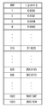
図2は、JNDインデックスを説明する図である。JNDインデックスはインデックス値と輝度値が対応づけられた対応表である。
GSDF処理の実装例をより具体的に説明する。GSDF処理では、DICOM part14で定義された、最大輝度値に応じて定められた値(JND値)にマッピングする処理を行う。RGBに最大値である1023を入力しパネルで輝度を測定し目標の最大輝度となるようバックライト調整を行った後、それ以下の入力信号で測定輝度が最大輝度のJND値と比例するようマッピングされた値をディスプレイのLUTとして保管する。このLUTはディスプレイ製造工程で設定されるか、ユーザのPCから設定される。GSDF処理では入力信号をこのLUTにもとづいて変換することでGSDFの特性の出力信号が得られる。LUTのデータはカラーガンマ処理と同様、CPUによって電源投入時に設定される。
例えば最大輝度を300cd/m2とした時、図2の表(JNDインデックス)からJND値の最大は630となる。入力INが10bitの場合、630*(IN/1023)が各階調のJND値で、例えばIN=512の場合は630*512/1023=315が対応するJND値となり、図2の表からそのときの輝度値は27.1cd/m2である。モノクロ信号の場合、信号源(PC)からはリニアな特性で供給され、ディスプレイ側でGSDF特性を実現する。
再び、図1を参照する。混合部26は、カラーガンマ処理部12による2.2ガンマ出力値D1とGSDF処理部14によるGSDF出力値D2(これらの出力値はいずれもRGB値で与えられる)をリミッタ22の出力値である彩度値Kに応じて混合する。彩度値Kが0であればGSDF出力値D2が100%、彩度値Kが上限値(実施例では512)であれば2.2ガンマ出力値D1が100%選択される。彩度値Kがちょうど真ん中の値(実施例では256)であれば2.2ガンマ出力値D1とGSDF出力値D2の混合比が50%対50%となる。一般に、2.2ガンマ出力値D1とGSDF出力値D2の混合比は、K/512:(512-K)/512で与えられる。
ただし、リミッタ22による画素の彩度値とエリア検出処理部30によるエリア検出彩度値を組み合わせる場合は、リミッタ22による彩度値とエリア検出処理部30によるエリア検出彩度値の大きい方の値が最大値選択部24により選択されて彩度値Kとして使用されることに留意する。
入力値D1、D2と、最大値512の彩度値Kが入力されたとき、混合部26の出力OUTは次式で与えられる。
OUT=(K*D1+(512-K)*D2)/512
ここでD1は2.2ガンマ出力値、D2はGSDF出力値、Kは彩度値である。
OUT=(K*D1+(512-K)*D2)/512
ここでD1は2.2ガンマ出力値、D2はGSDF出力値、Kは彩度値である。
マトリクス部16は、RGB信号から輝度信号(Y)および色差信号(R-Y、B-Y)に変換する処理を行う。ITU-R BT.709準拠の場合、輝度信号Yは次式でRGB値から変換される。
Y=0.2126R+0.7152G+0.0722B
他方、色差信号B-Y、R-YはBおよびRから輝度信号Yを引くことにより得られる。
Y=0.2126R+0.7152G+0.0722B
他方、色差信号B-Y、R-YはBおよびRから輝度信号Yを引くことにより得られる。
加算部18は、2つの色差信号R-Y、B-Yを加算し、彩度信号を求める。色差信号は負の値も持つので、ここでは絶対値化した後に加算する。
割算部20は、加算部18で求めた彩度信号の値D3を、マトリクス部16で得られた輝度信号Yの値D4で割ることにより、正規化された彩度信号を求める。加算部18で求めた彩度信号の値はRGBそれぞれの入力値が大きければそれに依存して大きな値となってしまうため、暗い画像に対し明るい画像で同じ色の濃さでも検出結果に差がでてしまう。そこで彩度の判定が入力信号の大きさに依存しないよう、彩度信号値を輝度信号値で割算する。なお割算の結果は小数点以下となるため、割算の結果に対して例えば4096倍する係数をかけて整数化する。係数4096の場合、割算部20による出力値OUTは、次式で得られる。
OUT=4096*D3/D4
ここで、D3は加算部18により2つの色差信号の絶対値を加算して得られた彩度信号値であり、D4はマトリクス部16により得られた輝度信号値Yである。
OUT=4096*D3/D4
ここで、D3は加算部18により2つの色差信号の絶対値を加算して得られた彩度信号値であり、D4はマトリクス部16により得られた輝度信号値Yである。
リミッタ22は、正規化後の彩度信号を一定値に制限する。リミット値(上限値)は、混合部26による混合比が2.2ガンマ出力が100%の状態のときの値であり、実施例では512である。例えば、入力が12bitで0から4095までの値をとる場合、リミッタ22は513以上はクリップし512以下のみ出力する場合、入力値INと出力値OUTの関係は以下のようになる。
if(IN<=512) OUT=IN
else OUT=512
if(IN<=512) OUT=IN
else OUT=512
エリア検出処理部30は、エリア単位でカラー/モノクロの判定を行い、エリア検出彩度値を出力する。エリア検出処理部30は、色判定部32、色信号面積判定部34、同期信号処理部36、メモリ38、および補間部40を含む。
色判定部32は、入力信号である彩度信号が閾値よりも大きい場合に1(真)を出力、それ以外の場合は0(偽)を出力する。
色信号面積判定部34は、実施例では水平32画素、垂直32ラインの固定領域(エリア)毎に設定されるメモリ38に色判定部32の判定結果をカウントした結果を格納する。カウント値がその固定領域の色信号比率の度合い(「エリア検出彩度値」と呼ぶ)となる。
メモリ38は、前述のように色信号面積判定部34に用いるカウント値を固定領域(エリア)毎に保存する。
同期信号処理部36は、エリアの位置の特定を行い、色信号面積判定部34の開始点・終了点を決定し、エリアに対応したメモリのアドレスの生成とリードライト処理を行う。また、同期信号処理部36は補間部40で使用する画素のx座標、y座標を決定するための同期信号を生成する。
色信号面積判定部34の出力をそのまま使用した場合、領域間で段差が発生するため、補間部40は隣接する2つの領域の間で補間処理を行う。この補間処理は、一例として、領域の中心からの距離に応じて混合比を直線的に変えることで行われる直線補間処理である。補間処理は水平と垂直の両方で行われる。
最大値選択(MAX)部24は、リミッタ22からの画素の彩度信号とエリア検出処理部30の補間部40により補間処理された後のエリア彩度信号との間で大小の判定を行い、大きい値を出力とする。最大値選択部24の出力値は、彩度値Kとして混合部26に入力され、2.2ガンマ出力値とGSDF出力値を混合する混合比の計算に用いられる。
上記では、エリア検出処理部30を含む画像補正装置100の構成を説明したが、エリア検出処理部30はオプションの構成としてもよく、エリア検出処理部30を省いて、リミッタ22からの画素の彩度信号をそのまま混合部26に入力される彩度値Kとして用いる構成にしてもよい。
以上の構成の画像補正装置100による信号処理の流れを説明する。
カラーガンマ処理部12によるカラーガンマ処理とGSDF処理部14によるGSDF処理とは並列に実行される。また、割算部20およびリミッタ22による画素単位の彩度判定処理とエリア検出処理部30によるエリア単位の彩度判定処理とは並列に実行される。
入力端子よりRGB信号と同期信号が入力される。RGB信号のR、G、Bそれぞれのデータはカラーガンマ処理部12およびGSDF処理部14に入力され、カラーガンマ処理およびGSDF処理を施され、混合部26に入力される。
RGB信号はマトリクス部16にも入力され、色差信号R-Y、B-Yと輝度信号Yに変換される。
2つの色差信号R-Y、B-Yは絶対値化された後、加算部18により加算され、割算部20の割り算の分子D3として割算部20に入力される。輝度信号Yは割算部20の割り算の分母D4として割算部20に入力される。割算部20の出力D3/D4が画素毎の彩度信号となる。
画素毎の彩度信号はリミッタ22によりリミット処理され、最大値が例えば512に制限された後、最大値選択部24に入力される。リミット値(上限値)512は混合部26でカラーガンマ処理された入力信号Aの混合比が100%(最大)となる値である。
一方、加算部18の出力D3はエリア検出処理部30の色判定部32にも供給される。エリア検出処理部30の補間部40から出力されたエリア検出彩度信号も最大値選択部24に入力される。最大値選択部24は、画素単位の彩度信号とエリア単位の彩度信号の内、より大きい方を選択し、混合比Kとして混合部26に入力する。混合部26は、混合比Kに応じた比率でカラーガンマ処理信号とGSDF処理信号(モノクロ信号)を混合し、混合後のRGB信号RGB’をLCDパネルへ供給する。LCDパネルにはCPU10からのバックライト制御信号も供給される。
次にエリア検出処理部30によるエリア検出処理の詳細を説明する。
エリア検出の信号処理の流れを説明する。一般に映像信号は水平に連続した状態で一水平周期分のデータが入力され、水平ブランキングもしくは水平同期信号で分割され、次の垂直位置の画像信号が続き、有効ライン数回繰り返される。
水平・垂直の位置情報は同期信号入力を基にして同期信号処理部36で生成される。色信号面積判定部34は、同期信号処理部36により生成された位置情報をもとにエリア毎の色判定結果を累積加算し、メモリ38に保存する。
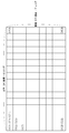
図3は、画像のエリアを説明する図である。実施例では水平32画素、垂直32ラインで1エリアが形成される。水平の総画素数が1280画素、垂直の総ライン数が1024ラインで、水平40エリア、垂直32エリアに分割されている。
エリアの最初のラインではエリア内の32画素分の色判定結果をカウントし、水平エリアの最終画素でそのエリアに割り当てられたメモリに書き込みを行う。次のエリアでも同様に検出した色判定結果のカウント数をメモリに書き込む処理を行う。そのエリアで10画素の色判定結果が真であれば、カウント値は10となる。
エリアの2ライン目以降では前のラインで記録したデータをそのエリアに割り当てられたメモリから読み出し、そのエリアで検出したカウント数を加算して再度メモリに書き込む。エリアの最終ラインとなる32ライン目の最終画素までカウントしたものがそのエリアの色判定結果となる。
その後、信号判定の対象は次のエリア列へ移り、そのエリアに対応したメモリに同様の処理を行い、最終的に全部で1280エリアの色判定結果が得られる。
図4は、エリアの色判定結果の例を説明する図である。例えば、水平が1画素目から32画素目、垂直が1ライン目から32ライン目までの画素で構成されるエリアにおいて、水平21画素目、垂直25ライン目から右および下が色判定部32により真と判定される場合、全部で12(画素)×8(ライン)=96個の画素において真となり、このカウント値がエリア検出彩度値C(1,1)のデータとなる。同様に当該エリアの真下のエリアではC(1,2)=384となり、当該エリアの右隣のエリアではC(2,1)=256となり、当該エリアの右斜め下のエリアではC(2,2)=1024となる。
以上の処理で得た1フレーム分のエリア検出彩度値は次の映像フレームで読み出される。
各エリアで検出されたエリア検出彩度値Cをエリア内の画素の彩度値として用いた場合、隣接するエリアとの境界で不自然な段差が生じることがある。そこで、エリア内の画素の彩度値を、当該エリアのエリア検出彩度値に隣接エリアのエリア検出彩度値を組み合わせて補間することにより平準化して求める。水平1エリア目、垂直1エリア目のエリアについて補間処理を行うため、自分自身のエリアで1フレーム前に検出したエリア検出彩度値C(1,1)とその1エリア下のエリア検出彩度値C(1,2)、右隣のエリア検出彩度値C(2,1)、右下のエリア検出彩度値C(2,2)の4データを使用する。ここでC(x,y)のxは水平エリア番号、yは垂直エリア番号とする。
水平xエリア目、垂直yエリア目の水平距離h、垂直距離vの点をP(x,y)(h,v)と定義し、点Pにおける補間後のエリア検出彩度値をH(x,y)(h,v)と定義する。
エリアの中心を原点とし、中心からの水平距離hと垂直距離vに応じて4つのエリア検出彩度値Cを次式で加算することにより、補間後のエリア検出彩度値H(1,1)(h,v)が得られる。
H(1,1)(h,v)=((C(1,1)*(32-h)+C(1,2)*h)*(32-v)+(C(2,1)*(32-h)+C(2,2)*h)*v)/1024
H(1,1)(h,v)=((C(1,1)*(32-h)+C(1,2)*h)*(32-v)+(C(2,1)*(32-h)+C(2,2)*h)*v)/1024
なお、画面を構成する最も上端、下端、左端、右端となるエリアでは中点より外側の補間データが存在しないためh=0もしくはv=0として計算する。
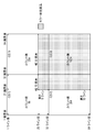
図5~図7は、エリア中心に対する画素の水平距離および垂直距離を説明する図である。
一般に水平・垂直の画素位置にもとづいてエリア番号とエリア中心からの距離を求める演算を説明する。水平・垂直とも画素の位置・ライン数に対しエリアサイズの1/2である16を加え、32で割った数がエリア番号、余りがエリア中心からの距離となる。例えば水平312画素目、垂直100ライン目の画素は、312+16=32*10+8、100+16=32*3+20であることから、水平エリア番号xは10、垂直エリア番号yは3、エリア中心からの水平距離hは8、垂直距離vは20である。すなわち、水平312画素目、垂直100ライン目の画素の点はP(10,3)(8,20)である(図5参照)。
この点P(10,3)(8,20)における補間後のエリア検出彩度値は、水平10エリア目、垂直3エリア目のエリアのエリア検出彩度値C(10,3)と、その1エリア下のエリア検出彩度値C(10,4)、右隣のエリア検出彩度値C(11,3)、右下のエリア検出彩度値C(11,4)を上述のように水平距離8、垂直距離20に応じて加算して算出されるエリア検出彩度値H(10,3)(8,20)である。
ただし、垂直16ライン未満の、例えば6ライン目、水平24画素目の場合、垂直の演算結果6+16=22は32以下であり、1から始まるべきエリア番号が0となってしまうため、22=32-10と考え、マイナスの値は0にクリップし、水平は24+16=32+8より、P(1,1)(8,0)と考えるものとする(図6参照)。水平も同様である。水平16画素未満の場合も同様に水平エリア番号を1、水平距離を0とする。
また、1010ライン目は1010+16=1026=32*32+2であるが、H(x,32)(h,2)の演算に必要なエリア検出彩度値C(x,33)は存在しない。この場合は垂直距離を0とみなし、C(x,33)に係る係数を0とすることで問題を回避するものとする(図7参照)。水平も同様に、16加算後1280を超える1265以上の画素では水平距離を0とする。
以上の処理によって補間処理が行われ、補間後のエリア検出彩度信号が画素毎に階調をもった値で得ることができる。
以上述べたように、本実施の形態の画像補正装置100によれば、カラーガンマ処理部12による2.2ガンマ出力値とGSDF処理部14によるGSDF出力値を彩度値Kから得られる混合比で混合することにより、画素値を補正する。彩度値Kは最大512であり、512段階で2.2ガンマ出力値とGSDF出力値の混合比が調整される。カラーとモノクロの判別を2値で判定するのではなく、512段階でカラーとモノクロを重みづけし、画素毎に判定結果に応じて2.2ガンマ処理とGSDF処理の両方のガンマカーブの処理を行った後の信号をカラー判別の割合に応じて混合する。すなわち、カラー判定の度合いが大きいほど2.2ガンマ処理に近づけ、モノクロ判定の度合いが大きいほどGSDF処理に近づけることで、カラー画像領域とモノクロ画像領域の境界に不自然な段差が発生することを避けることができる。
さらに、リミッタ22による画素単位の彩度値と、エリア検出処理部30によるエリア単位の彩度値のいずれか大きい方を用いて彩度値Kを決定することにより、カラー/モノクロ領域の誤判定を避けることができる。カラーの割合が高い領域内に色の薄い部分やモノクロ部分があっても、エリア判定が優先されるため、これらの部分をモノクロ領域と誤判定することを回避することができる。このように、画素単位の彩度値の検出結果をさらにエリア単位で加算してエリア単位の検出彩度値とし、画素単位の彩度値の判別結果と合成することで検出精度を向上させることができる。また、エリア単位の判定の際、エリアの境界が目立たなくなるよう平滑処理した補間後のエリア検出彩度値を用いることでエリアの境界で不自然な段差が生じるのを回避することができる。
本実施の形態によれば、画素単位の検出を行うことでモノクロ画像中に描画される線分(CAD、スケール等)や小面積のカラー画像(エラストグラフィ、カラードップラー等)の検出も可能である。完全な画素単位の検出の場合、輝度信号の変化が増幅されてしまい、カラー画像の色の薄い部分で階調歪が発生する場合があったが、エリア検出を併用することでこのような問題を改善することができた。また、判別結果を2値で扱わず、重みづけをすることで、画素単位の検出にエリア検出を組み合わせるという簡便な補正処理でも画像のカラー/モノクロ判別の破綻を防止することができる。
以上、本発明を実施の形態をもとに説明した。実施の形態は例示であり、それらの各構成要素や各処理プロセスの組合せにいろいろな変形例が可能なこと、またそうした変形例も本発明の範囲にあることは当業者に理解されるところである。
10 CPU、 12 カラーガンマ処理部、 14 GSDF処理部、 16 マトリクス部、 18 加算部、 20 割算部、 22 リミッタ、 24 最大値選択部、 26 混合部、 30 エリア検出処理部、 32 色判定部、 34 色信号面積判定部、 36 同期信号処理部、 38 メモリ、 40 補間部、 100 画像補正装置。
本発明は、画像補正技術に利用できる。
Claims (6)
- 入力画像に画素単位でカラー用のガンマ補正を施すカラーガンマ処理部と、
前記入力画像に画素単位でモノクロ用のガンマ補正を施すモノクロガンマ処理部と、
前記入力画像の画素単位の彩度値にもとづく混合比で、前記カラーガンマ処理部によるカラー用のガンマ補正値と前記モノクロガンマ処理部によるモノクロ用のガンマ補正値を混合して、前記入力画像の画素のガンマ補正値を出力する混合部とを含むことを特徴とする画像補正装置。 - 前記入力画像のエリア単位で彩度値を検出するエリア検出処理部と、
前記入力画像の画素単位の彩度値と前記エリア検出処理部により検出された前記入力画像のエリア単位の彩度値のいずれか一方を選択する選択部とをさらに含み、
前記混合部は、前記選択部により選択された彩度値にもとづく混合比で、前記カラーガンマ処理部によるカラー用のガンマ補正値と前記モノクロガンマ処理部によるモノクロ用のガンマ補正値を混合することを特徴とする請求項1に記載の画像補正装置。 - 前記選択部は、前記入力画像の画素単位の彩度値と前記エリア検出処理部により検出された前記入力画像のエリア単位の彩度値のいずれか大きい方を選択することを特徴とする請求項2に記載の画像補正装置。
- 前記エリア検出処理部は、エリア単位で検出された彩度値を隣接エリアの彩度値を用いて補間することにより、当該エリア内の画素の彩度値を求める補間部を含むことを特徴とする請求項2または3に記載の画像補正装置。
- 入力画像に画素単位でカラー用のガンマ補正を施すカラーガンマ処理ステップと、
前記入力画像に画素単位でモノクロ用のガンマ補正を施すモノクロガンマ処理ステップと、
前記入力画像の画素単位の彩度値にもとづく混合比で、前記カラーガンマ処理ステップによるカラー用のガンマ補正値と前記モノクロガンマ処理ステップによるモノクロ用のガンマ補正値を混合して、前記入力画像の画素のガンマ補正値を出力する混合ステップとを含むことを特徴とする画像補正方法。 - 入力画像に画素単位でカラー用のガンマ補正を施すカラーガンマ処理ステップと、
前記入力画像に画素単位でモノクロ用のガンマ補正を施すモノクロガンマ処理ステップと、
前記入力画像の画素単位の彩度値にもとづく混合比で、前記カラーガンマ処理ステップによるカラー用のガンマ補正値と前記モノクロガンマ処理ステップによるモノクロ用のガンマ補正値を混合して、前記入力画像の画素のガンマ補正値を出力する混合ステップとをコンピュータに実行させることを特徴とする画像補正プログラム。
Priority Applications (1)
| Application Number | Priority Date | Filing Date | Title |
|---|---|---|---|
| US15/671,047 US10346711B2 (en) | 2015-03-23 | 2017-08-07 | Image correction device, image correction method, and image correction program |
Applications Claiming Priority (2)
| Application Number | Priority Date | Filing Date | Title |
|---|---|---|---|
| JP2015-059736 | 2015-03-23 | ||
| JP2015059736A JP6277984B2 (ja) | 2015-03-23 | 2015-03-23 | 画像補正装置、画像補正方法及び画像補正プログラム |
Related Child Applications (1)
| Application Number | Title | Priority Date | Filing Date |
|---|---|---|---|
| US15/671,047 Continuation US10346711B2 (en) | 2015-03-23 | 2017-08-07 | Image correction device, image correction method, and image correction program |
Publications (1)
| Publication Number | Publication Date |
|---|---|
| WO2016151944A1 true WO2016151944A1 (ja) | 2016-09-29 |
Family
ID=56978077
Family Applications (1)
| Application Number | Title | Priority Date | Filing Date |
|---|---|---|---|
| PCT/JP2015/083159 Ceased WO2016151944A1 (ja) | 2015-03-23 | 2015-11-26 | 画像補正装置、画像補正方法及び画像補正プログラム |
Country Status (3)
| Country | Link |
|---|---|
| US (1) | US10346711B2 (ja) |
| JP (1) | JP6277984B2 (ja) |
| WO (1) | WO2016151944A1 (ja) |
Families Citing this family (2)
| Publication number | Priority date | Publication date | Assignee | Title |
|---|---|---|---|---|
| KR102453070B1 (ko) | 2018-06-05 | 2022-10-07 | 에이조 가부시키가이샤 | 화상 처리 장치 및 화상 처리 프로그램 |
| US10819885B2 (en) * | 2018-11-09 | 2020-10-27 | Chongqing Advance Display Technology Research | Gamma value tuning method and device of display panel |
Citations (5)
| Publication number | Priority date | Publication date | Assignee | Title |
|---|---|---|---|---|
| JP2011232382A (ja) * | 2010-04-23 | 2011-11-17 | Nanao Corp | 画像表示装置、画像領域検出方法及びコンピュータプログラム |
| JP4977255B1 (ja) * | 2011-03-31 | 2012-07-18 | 株式会社ナナオ | 表示装置、画像処理装置、画像領域検出方法、画像処理方法及びコンピュータプログラム |
| JP2013008002A (ja) * | 2011-05-23 | 2013-01-10 | Canon Inc | 画像出力装置、画像出力装置の制御方法、及び、プログラム |
| JP2013089074A (ja) * | 2011-10-19 | 2013-05-13 | Nanao Corp | 表示装置及び表示方法 |
| WO2014057586A1 (ja) * | 2012-10-12 | 2014-04-17 | Necディスプレイソリューションズ株式会社 | 表示装置及び表示方法 |
Family Cites Families (22)
| Publication number | Priority date | Publication date | Assignee | Title |
|---|---|---|---|---|
| US20020173721A1 (en) * | 1999-08-20 | 2002-11-21 | Novasonics, Inc. | User interface for handheld imaging devices |
| US6947593B2 (en) * | 2001-10-05 | 2005-09-20 | Hewlett-Packard Development Company, Lp. | Digital image processing |
| US6844881B1 (en) * | 2002-03-29 | 2005-01-18 | Apple Computer, Inc. | Method and apparatus for improved color correction |
| DE50212936D1 (de) * | 2002-10-24 | 2008-12-04 | L 1 Identity Solutions Ag | Prüfung von Bildaufnahmen von Personen |
| KR101092539B1 (ko) * | 2005-02-18 | 2011-12-14 | 삼성전자주식회사 | 화이트 밸런스를 자동 조정하는 영상장치 및 그의 화이트밸런스 조정 방법 |
| JP2006237856A (ja) * | 2005-02-23 | 2006-09-07 | Ricoh Co Ltd | 画像処理装置、画像処理方法、その方法をコンピュータに実行させるプログラム、および記録媒体 |
| EP2472507B1 (en) * | 2005-10-14 | 2016-02-10 | Samsung Display Co., Ltd. | Improved gamut mapping and subpixel rendering systems and methods |
| JP4550727B2 (ja) * | 2005-12-06 | 2010-09-22 | 株式会社リコー | 画像処理装置及び画像形成装置 |
| US8107762B2 (en) * | 2006-03-17 | 2012-01-31 | Qualcomm Incorporated | Systems, methods, and apparatus for exposure control |
| JP5043595B2 (ja) * | 2007-10-23 | 2012-10-10 | 富士フイルム株式会社 | 撮影装置および内視鏡システム |
| JP5097574B2 (ja) * | 2008-02-26 | 2012-12-12 | 株式会社リコー | 画像処理装置、画像処理方法、画像処理プログラム及び記録媒体 |
| JP4692603B2 (ja) * | 2008-09-29 | 2011-06-01 | ブラザー工業株式会社 | プロファイル補正装置、プロファイル補正プログラム及びプロファイル補正方法 |
| US8749635B2 (en) * | 2009-06-03 | 2014-06-10 | Flir Systems, Inc. | Infrared camera systems and methods for dual sensor applications |
| US8630488B2 (en) * | 2011-11-30 | 2014-01-14 | Konica Minolta Laboratory U.S.A., Inc. | Creating a duotone color effect using an ICC profile |
| JP5843662B2 (ja) * | 2012-03-05 | 2016-01-13 | シャープ株式会社 | 表示装置及びテレビジョン受信機 |
| JP6157138B2 (ja) * | 2012-03-30 | 2017-07-05 | キヤノン株式会社 | 画像処理装置 |
| US9135718B2 (en) * | 2012-03-30 | 2015-09-15 | Canon Kabushiki Kaisha | Image processing apparatus and control method therefor |
| WO2014203082A2 (en) * | 2013-05-28 | 2014-12-24 | Marvell World Trade Ltd. | Systems and methods for red-eye correction |
| KR102113109B1 (ko) * | 2013-10-01 | 2020-05-21 | 삼성디스플레이 주식회사 | 유기 발광 표시 장치의 구동 방법 및 유기 발광 표시 장치 |
| KR102288334B1 (ko) * | 2015-02-03 | 2021-08-11 | 삼성디스플레이 주식회사 | 표시 장치 및 이의 로고 영역 휘도 조절 방법 |
| CN104575405B (zh) * | 2015-02-04 | 2017-08-25 | 京东方科技集团股份有限公司 | 一种调节显示装置背光亮度的方法、显示装置 |
| US10360868B2 (en) * | 2015-12-09 | 2019-07-23 | Hisense Electric Co., Ltd. | Image processing method and liquid crystal display device |
-
2015
- 2015-03-23 JP JP2015059736A patent/JP6277984B2/ja active Active
- 2015-11-26 WO PCT/JP2015/083159 patent/WO2016151944A1/ja not_active Ceased
-
2017
- 2017-08-07 US US15/671,047 patent/US10346711B2/en active Active
Patent Citations (5)
| Publication number | Priority date | Publication date | Assignee | Title |
|---|---|---|---|---|
| JP2011232382A (ja) * | 2010-04-23 | 2011-11-17 | Nanao Corp | 画像表示装置、画像領域検出方法及びコンピュータプログラム |
| JP4977255B1 (ja) * | 2011-03-31 | 2012-07-18 | 株式会社ナナオ | 表示装置、画像処理装置、画像領域検出方法、画像処理方法及びコンピュータプログラム |
| JP2013008002A (ja) * | 2011-05-23 | 2013-01-10 | Canon Inc | 画像出力装置、画像出力装置の制御方法、及び、プログラム |
| JP2013089074A (ja) * | 2011-10-19 | 2013-05-13 | Nanao Corp | 表示装置及び表示方法 |
| WO2014057586A1 (ja) * | 2012-10-12 | 2014-04-17 | Necディスプレイソリューションズ株式会社 | 表示装置及び表示方法 |
Also Published As
| Publication number | Publication date |
|---|---|
| JP6277984B2 (ja) | 2018-02-14 |
| US10346711B2 (en) | 2019-07-09 |
| JP2016180787A (ja) | 2016-10-13 |
| US20170337446A1 (en) | 2017-11-23 |
Similar Documents
| Publication | Publication Date | Title |
|---|---|---|
| EP3770899A1 (en) | Screen brightness control method and device, and terminal device | |
| CN106575496B (zh) | 显示装置、灰度校正映射生成装置、灰度校正映射生成方法及程序 | |
| CN111916031A (zh) | 显示方法及显示装置 | |
| KR20160059021A (ko) | 표시 패널 구동 장치 및 이를 포함하는 표시 장치 | |
| CN111312141A (zh) | 色域的调整方法及装置 | |
| KR20190001466A (ko) | 영상을 처리하기 위한 방법 및 디스플레이 장치 | |
| US10152945B2 (en) | Image processing apparatus capable of performing conversion on input image data for wide dynamic range | |
| JP6779695B2 (ja) | 画像処理装置及びその制御方法、表示装置 | |
| JP2016201026A (ja) | 画像処理装置及びプログラム | |
| US11763777B2 (en) | Image display device, image display system, image display method, and computer program for providing a low-luminance grayscale standard display function (GSDF) display | |
| JP4870609B2 (ja) | 調整方法、調整システム、表示装置、調整用装置及びコンピュータプログラム | |
| JP2009177569A (ja) | 液晶型映像表示装置とそのホワイトバランス制御方法 | |
| JP2010160509A (ja) | 調整方法及び表示装置 | |
| JP6277984B2 (ja) | 画像補正装置、画像補正方法及び画像補正プログラム | |
| JP4490899B2 (ja) | 調整方法及び表示装置 | |
| CN116264056A (zh) | 显示设备的亮度调整方法及装置、电子设备、存储介质 | |
| KR20080056624A (ko) | 디스플레이의 그레이 레벨 대 휘도 곡선을 신속히 생성하는방법 및 장치 | |
| CN115862534B (zh) | 颜色校正方法、装置、电子设备及存储介质 | |
| CN108628715B (zh) | 一种显示设备的显示效果校正方法及装置 | |
| JP5939765B2 (ja) | キャリブレーション装置、その制御方法、画像表示装置、及び画像表示システム | |
| CN119943002B (zh) | 一种显示器色彩克隆校准方法、装置、电子终端及存储介质 | |
| JP6645668B2 (ja) | 画像表示装置および画像表示方法 | |
| JP7475190B2 (ja) | 画像処理装置、画像処理方法、および制御プログラム | |
| CN116703758B (zh) | 一种灰阶医学图像的色温增强方法及装置 | |
| JP5946281B2 (ja) | 画像処理装置、画像表示システム、および画像表示方法 |
Legal Events
| Date | Code | Title | Description |
|---|---|---|---|
| 121 | Ep: the epo has been informed by wipo that ep was designated in this application |
Ref document number: 15886496 Country of ref document: EP Kind code of ref document: A1 |
|
| NENP | Non-entry into the national phase |
Ref country code: DE |
|
| 122 | Ep: pct application non-entry in european phase |
Ref document number: 15886496 Country of ref document: EP Kind code of ref document: A1 |