WO2016151734A1 - 撮像装置、画像処理装置、およびデジタルカメラ - Google Patents
撮像装置、画像処理装置、およびデジタルカメラ Download PDFInfo
- Publication number
- WO2016151734A1 WO2016151734A1 PCT/JP2015/058769 JP2015058769W WO2016151734A1 WO 2016151734 A1 WO2016151734 A1 WO 2016151734A1 JP 2015058769 W JP2015058769 W JP 2015058769W WO 2016151734 A1 WO2016151734 A1 WO 2016151734A1
- Authority
- WO
- WIPO (PCT)
- Prior art keywords
- image data
- pixels
- pixel
- image
- frame rate
- Prior art date
- Legal status (The legal status is an assumption and is not a legal conclusion. Google has not performed a legal analysis and makes no representation as to the accuracy of the status listed.)
- Ceased
Links
Images






Classifications
-
- H—ELECTRICITY
- H04—ELECTRIC COMMUNICATION TECHNIQUE
- H04N—PICTORIAL COMMUNICATION, e.g. TELEVISION
- H04N23/00—Cameras or camera modules comprising electronic image sensors; Control thereof
- H04N23/60—Control of cameras or camera modules
-
- H—ELECTRICITY
- H04—ELECTRIC COMMUNICATION TECHNIQUE
- H04N—PICTORIAL COMMUNICATION, e.g. TELEVISION
- H04N25/00—Circuitry of solid-state image sensors [SSIS]; Control thereof
- H04N25/40—Extracting pixel data from image sensors by controlling scanning circuits, e.g. by modifying the number of pixels sampled or to be sampled
Definitions
- the present invention relates to an imaging device, an image processing device, and a digital camera, and more particularly to a technique effective for improving the visibility of a subject having a high moving speed.
- This digital camera projects an image of a subject on an imaging sensor, which is an assembly of multiple pixels made of semiconductors, through a lens, and measures the amount of light emitted for each pixel. Acquire a 3D image.
- an optical finder is used in the era of film cameras.
- Optical viewfinders project the light incident from the taking lens onto the focus glass, such as those with an optical viewfinder at a position different from the taking lens used in compact cameras, etc., and single lens reflex cameras. And there are things that you can see in advance the image that actually appears on the film.
- LCD Liquid Crystal Display
- EVF Electronic View Finder
- the electronic viewfinder has a liquid crystal display installed at a position corresponding to the focus glass of a single-lens reflex camera, and a user, for example, about 1 m ahead of the naked eye in the space, uses a lens to focus with his / her own eyes. It is a finder that displays a large screen image at a position where it can be used.
- the basic operation of a digital camera when viewing an object using a liquid crystal display or electronic viewfinder is to generate a moving image signal by periodically capturing images in units such as frames after the power is turned on. It is common to display a moving image, so-called live view image, based on a moving image signal.
- the digital camera stops generating the moving image signal and performs imaging to generate a still image signal.
- the live view image cannot be updated.
- a phenomenon occurs in which the same image is displayed on a liquid crystal display or an electronic viewfinder, or the liquid crystal display or the electronic viewfinder is blacked out and no image is displayed.
- a technique for shortening the blackout time in such continuous shooting for example, a plurality of pixels arranged on a solid-state imaging device are divided into a plurality of groups, and a still image is obtained from the pixels belonging to the group in the divided group units.
- the read signal is read out, the moving image signal is read out from any of the plurality of pixels during the reading period, and in the reading of the still image signal, the still image signal is read out by the first reading circuit.
- a method in which a moving image signal is read by a second reading circuit see, for example, Patent Document 1).
- Modern digital still cameras are also capable of shooting moving images, and the specifications require that the number of pixels of a still image to be shot is considerably larger than the number of pixels that can be displayed on a liquid crystal display.
- this method is applied to the above-mentioned specific continuous shooting speed.
- the entire imaging screen is divided into three fields, and read data from one of these fields is displayed as a moving image, and moving image reading is performed compared to reading a still image full screen. Time is only 1/3.
- the reading interval of one horizontal line is converted to a 2k high-definition moving image even if the technique of Patent Document 1 is used. Compared to 1/3 ⁇ 4 times. In addition, since the number of pixels in one horizontal line is four times, the readout time for one line is also four times.
- the effect of reducing the blackout time is small and the subject has a fast moving speed. It will be insufficient to shoot. Therefore, it is limited to continuously photographing a stationary subject or a subject with a relatively slow moving speed.
- An object of the present invention is to provide a technique capable of generating a moving image having the same number of pixels as all pixels of a sensor at the same frame rate as a moving image at the same frame rate as that of the moving image.
- a typical imaging apparatus includes an imaging sensor, a first signal processing unit, a second signal processing unit, a display unit, a first expansion unit, a second expansion unit, and a memory unit.
- the imaging sensor converts an optical image captured by a plurality of pixels arranged in an array on the imaging surface into an electrical signal.
- the first signal processing unit digitally processes an electrical signal read from the first pixel among a plurality of pixels included in the imaging sensor.
- the second signal processing unit digitally processes an electrical signal read from the second pixel among the plurality of pixels of the imaging sensor.
- the display unit displays the first image data digitally processed by the first signal processing unit.
- the first decompression unit is compressed using the correlation between frames of the first image data having the first number of pixels and the first frame rate digitally processed by the first signal processing unit.
- the compressed image data is decompressed.
- the second decompressing unit generates a moving image having a frame rate equal to or higher than the frame rate of the first image data based on the first compressed image data and the second compressed image data.
- the memory unit stores the first compressed image data and the second compressed image data.
- the second compressed image data includes the second image data having a second frame rate slower than the number of the second pixels and the first frame rate digitally processed by the second signal processing unit. This is compressed data.
- the second pixel has a larger number of pixels than the first pixel.
- the first image data has the number of pixels that matches the format defined in the moving image format of the digital television.
- the visibility of the captured image can be improved.
- the constituent elements are not necessarily indispensable unless otherwise specified and apparently essential in principle. Needless to say.
- FIG. 1 is an explanatory diagram illustrating an example of a configuration of a digital camera according to one embodiment.
- the digital camera which is an imaging device has an objective lens 10 as shown in FIG.
- the image of the subject SB captured through the objective lens 10 is projected onto the image sensor 11 that is an aggregate of a plurality of pixels arranged in a two-dimensional manner on the imaging surface.
- the objective lens 10 has, for example, a three-group three-lens configuration, a so-called triplet configuration.
- the imaging sensor 11 converts the optical image of the subject SB projected from the objective lens 10 into an electrical signal, and acquires a captured image.
- FIG. 1 shows a case where a moving object such as a bird flying at high speed is taken as a subject SB as an object to be taken by a digital camera.
- the imaging sensor 11 is connected to a DSP 12 serving as a first signal processing unit and a DSP 13 serving as a second signal processing unit.
- the DSP 12 performs image processing of a moving image acquired by a pixel A of the image sensor 11 described later.
- the DSP 13 performs image processing of a moving image acquired by a pixel B of the imaging sensor 11 described later.
- the DSP / DSP 13 is connected to an encoder / decoder 14.
- the encoder / decoder 14 compresses (encodes) or reproduces (decodes) the image processing results output from the DSP 12 and the DSP 13.
- a memory 15 and a memory 16 are connected to the encoder / decoder 14, respectively.
- the memory 15 stores the data of the DSP 12 processed by the encoder / decoder 14.
- the memory 16 stores the DSP 13 data processed by the encoder / decoder 14.
- the image of the subject SB imaged on the image sensor 11 through the objective lens 10 is displayed on an electronic viewfinder (hereinafter referred to as EVF) 25 and a liquid crystal display 26.
- EVF electronic viewfinder
- the EVF 25 and the liquid crystal display 26 serve as a display unit.
- the encoder / decoder 14 is connected to an HDMI (High Definition Multimedia Interface) terminal 17 and a USB (Universal Serial Bus) terminal 18.
- HDMI High Definition Multimedia Interface
- USB Universal Serial Bus
- the HDMI terminal 17 is a terminal corresponding to an interface standard such as digital video or audio, and outputs a moving image to an externally connected high-vision monitor or the like.
- the USB terminal 18 is a connection terminal with an external device, and outputs a moving image to an external memory, for example.
- the moving image output to the EVF 25 or the liquid crystal display 26 has the number of pixels and the frame rate conforming to the moving image format of the digital television.
- the moving image acquired by the pixel A of the image sensor 11 shown in FIG. 2C described later is compressed according to the moving image compression format by the DSP 12 and the encoder / decoder 14 and stored in the memory 15.
- the image compression format is, for example, MPEG4 (Moving Picture Experts Group Group 4) or H.264. H.264 or the like.
- the memory 15 is different from the memory 16 for recording still images, but the memory 15 and the memory 16 may be configured as one memory.
- the memory may be constituted by a removable memory such as an SD memory card.
- the pixel B which is a still image pixel shown in FIG. 2B to be described later, from the image sensor 11 via the DSP 13 when a still image is shot by pressing a shutter button (not shown) of the digital camera.
- the encoder / decoder 14 performs still image compression using JPEG (Joint Photographic Experts Group) compression by discrete cosine transform, Huffman coding, etc. as an example, and then saves it in the memory 16.
- JPEG Joint Photographic Experts Group
- the storage process in the memory 16 is performed at a speed equal to or less than the reading speed from the image sensor 11, that is, the speed of 1 sheet / second.
- Both the memory 15 and the memory 16 may be removable memory such as an SD memory card.
- the memory 15 may be a hard disk built in the digital camera, and the memory 16 may be a memory such as a removable SD memory card.
- the encoder / decoder 14 uses the information of the 8 k ⁇ 1 fps still image and the 2 k ⁇ 30 fps moving image in addition to the above-described moving image and still image compression, and uses a high-definition, high frame rate of about 8 k ⁇ 30 fps. Can be generated.
- 2k ⁇ 30 fps moving image data having information of the macroblock movement vector VT is sent to the encoder / decoder 14, and the moving image pixel A belonging to the macroblock is transmitted.
- the processing is performed on the assumption that the still image pixel B belonging to the position moves according to the same movement vector information.
- a high-definition moving image of 8 k ⁇ 30 fps can be stored in an SD memory card or the like.
- a digital camera is shown as an example of the imaging device.
- the imaging device is not limited to the digital camera, and may be various forms such as a terminal having a camera function such as a tablet or a smartphone. Can be used.
- FIG. 2 is an explanatory diagram showing an example of the structure of the image sensor 11 used in the digital camera of FIG.
- FIG. 2A shows the pixel configuration of the image sensor 11.
- the pixel A shown in FIG. 2A is a pixel that is output to the EVF 25 and the like in FIG. 1, and the pixel B shown in FIG. 2A is used when shooting a still image. Pixel.
- the first pixel, pixel A is a pixel processed by the DSP 12 and the encoder / decoder 14.
- FIG. 2B shows a configuration example of one pixel 11 a included in the imaging sensor 11.
- Both the pixel A and the pixel B are composed of a pixel 11a shown in FIG.
- the image sensor 11 is a color sensor, and the pixel 11a includes four light receiving sensors R, G, G, and B as shown in FIG.
- the image sensor 11 is provided with three color filters of R (Red), G (Green), and B (Blue), and the three primary colors of light can be simultaneously captured by one pixel 11a.
- G (Green) occupies the largest proportion. Therefore, the pixel 11a has two G (Green) light receiving sensors G, and information on the light to be photographed can be acquired better.
- FIG. 2C is an explanatory diagram when the image sensor 11 is a CCD (Charge Coupled Device) image sensor.
- CCD Charge Coupled Device
- the CCD image sensor has a configuration in which a gate 20 is connected to each pixel 11a. Signals output from the respective pixels 11a are sequentially read out through the gate 20.
- the output from the pixel A reads image information as an EVF pixel displayed on the EVF 25, and the output from the pixel B reads image information as a still image pixel that becomes a still image pixel. .
- the still image pixel 31 is read at a rate of one frame per second.
- the EVF image 30 is read at a high speed regardless of the reading speed of the pixel B, and the EVF 25 of FIG. A moving image is displayed on the display 26.
- FIG. 2D is an explanatory diagram in the case where the imaging sensor 11 is a CMOS (Complementary Metal Oxide Semiconductor) image sensor.
- CMOS Complementary Metal Oxide Semiconductor
- the pixel selection switch 21 is connected to each of the pixels 11 a included in the image sensor 11. Arbitrary pixels can be read by selecting the timing to read from each pixel 11a using the pixel selection switch 21.
- This selection is performed in the order of the pixels 11a as in the CCD image sensor shown in FIG.
- the pixel A performs high-speed reading regardless of the reading of the pixel B, so that a moving image can be displayed on the EVF 25 or the liquid crystal display 26 in FIG. .
- the CMOS image sensor adopts a rolling shutter system in which imaging and reading are performed in order for each pixel instead of simultaneously on the entire surface of the imaging sensor. Therefore, for example, in the case of reading one frame per second as described above, for example, about 1 between the imaging timing of the upper left pixel 11a and the imaging timing of the lower right pixel 11a of the imaging sensor 11 in FIG. There is a time difference of seconds.
- CMOS image sensor In the case of a digital camera using a CMOS image sensor, for example, there is one that prevents distortion of an image by performing exposure in a short time using, for example, a mechanical shutter and simultaneously passing light through all pixels of the imaging sensor.
- the digital camera of FIG. 1 is a camera that captures a moving image
- the mechanical shutter as described above is not used
- the pixel B which is a pixel for capturing a still image, is in front of the pixel selection switch 21.
- a temporary buffer 22 is provided.
- Image distortion can be solved by a global shutter method in which all pixels of the image sensor 11 are photographed simultaneously, and data of all pixels 11a is read from the temporary buffer 22 over a period of 1 second after the photographing.
- the subject image visually recognized by the EVF 25 or the liquid crystal display 26 is continuously viewed and tracked without being blacked out. be able to.
- the number of pixels of the image acquired by the pixel A on the image sensor 11 conforms to the current high-definition digital television image format, and is, for example, 1920 ⁇ 1080 pixels ⁇ 60 fps or 1440 ⁇ 1080 pixels ⁇ 30 fps. Also good.
- FIG. 3 is an explanatory diagram showing an example of extracting a still image and information displayed on the EVF 25 from the information acquired by the imaging sensor 11 of FIG.
- FIG. 3A is the same as FIG. 2A, and FIG. 3B shows still image pixels.
- the still image pixel is the pixel B included in the imaging sensor 11 of FIG. 3A, and the portion corresponding to the pixel A is in a state where the pixel is missing.
- FIG. 3C shows an EVF pixel in the image sensor 11.
- the EVF pixel is composed of only the pixel A as shown in FIG. Therefore, the number of pixels is smaller than all the pixels of the image sensor 11.
- one pixel A is arranged in a ratio of 4 pixels in the horizontal direction ⁇ 4 pixels in the vertical direction on the light receiving surface. In that case, 2000 ⁇ 1000 pixels, which is the same as the number of pixels of 2K television. By reading out the pixel A having this small number of pixels, the reading speed of the pixel A can be performed at a high speed.
- one pixel A is arranged at a ratio of 4 pixels in the horizontal direction ⁇ 4 pixels in the vertical direction, but the arrangement ratio of the pixels A is 5 pixels or more in both the horizontal direction and the vertical direction.
- the ratio of the pixels in the horizontal direction and the pixels in the vertical direction may be different.
- 2K digital television broadcasting is based on the standard of displaying 2000 ⁇ 1000 images at 30 fps (2 fields / 1 frame), and can capture moving images of digital television using pixels A, and A high-definition still image far larger than the number of pixels can be acquired simultaneously.
- 4K digital television broadcasting has a standard of displaying a 4000 ⁇ 3000 image at 120 fps, and can capture a moving image of a digital television using the pixel A, and is far more than the number of pixels of a digital television. Many high-definition still images can be acquired simultaneously.
- FIG. 4 is an explanatory diagram showing an example of generating compressed information using a time axis difference of a moving image from information acquired by the image sensor 11 by the digital camera of FIG.
- FIGS. 4 to 10 described below is performed by an encoder / decoder 14 (particularly, the decoder 14a in FIG. 11) shown in FIG. 6 to be described later.
- I pictures In the compression of moving images, there are still images on the time axis (hereinafter referred to as I pictures), and the contents of the image change between the I picture and the next I picture over time. Are converted into information as fluctuation differences in the time axis direction (hereinafter, the one behind the I picture is referred to as the P picture, and the one before the I picture is referred to as the B picture).
- the I picture itself is subjected to JPEG compression by techniques such as discrete cosine transform and Huffman coding.
- JPEG compression by techniques such as discrete cosine transform and Huffman coding.
- discrete cosine transform and Huffman coding an example of informatization based on time-axis fluctuation difference of P pictures (and B pictures) is shown.
- the image shown on the left side is an I picture.
- the technology for acquiring time-axis fluctuation difference information based on the I picture is as follows.
- a subject in the macro block MB1 (represented by an equilateral triangle in FIG. 4) is recognized as a video pattern in the macro block MB1.
- the moved macroblock MB2 has the largest correlation with the macroblock MB1, but the macroblock MB1 and the macroblock MB2 are not exactly the same data, and between them is always an image because it is an image. Differences occur. By compressing and encoding this difference, data can be constructed with a much smaller amount of information than when the entire macroblock MB2 is compressed like an I picture.
- the P picture is generated by encoding the change in the coordinate position of the macro block MB2 highly correlated with the macro block MB1 on the I picture and the difference between the macro block MB1 and the macro block MB2. .
- This technique allows a plurality of P pictures to be recorded without the need to save the entire still picture, so that information can be generated at a large compression rate for moving picture information compression.
- the time-axis fluctuation difference is acquired by the same method using the I picture after the B picture. Since both the P picture and the B picture have less fluctuation as the time axis distance from the base I picture is smaller, efficient compression is possible.
- FIG. 5 is an explanatory diagram showing an example of generating compressed information using the time axis difference of moving images from information acquired by the image sensor 11 by the digital camera of FIG.
- FIG. 5A a technique for obtaining time-axis fluctuation difference information of P picture from I picture # 1, and a technique for obtaining time-axis fluctuation difference information of P picture # 2 from I picture # 1 in FIG. Is as shown in FIG.
- the interval between I picture # 1 and I picture # 2, that is, the number of P pictures and B pictures, may be fixed. If the image does not change dynamically, the interval is increased adaptively. You may perform operation of.
- FIG. 5B shows a technique for obtaining the P picture next to the I picture by returning the time from the next P picture, not from the I picture, especially when the image undergoes dynamic change.
- the macroblock of I picture # 1 (the area indicated by hatching in FIG. 5B) varies considerably in P picture # 1, and the next P picture # 2 is further changed. If the correlation is strong, P picture # 1 is skipped from I picture # 1, P picture # 2 is obtained, and one picture is returned from there to obtain P picture # 1.
- the method shown in FIG. 5 (b) is effective when an image undergoes a dynamic change for each frame image, and in this example, a relatively close image appears in every other cycle.
- the P picture # 2 is obtained from the I picture # 1 in FIG. 5 (b) far ahead of the I picture # 2 in FIG. 5 (b) like the B picture shown in FIG. 5 (a).
- this is effective for reducing the finally generated moving image data, in other words, for obtaining a high compression rate.
- FIG. 6 is an explanatory diagram showing an example in which the macro block MB3 is constructed by moving image shooting pixels acquired by the digital camera of FIG.
- the macroblock MB3 is composed of pixels A that are pixels for capturing moving images, and the size thereof is, for example, 8 pixels ⁇ 8 pixels as shown in FIG. Here, it is assumed that a triangular figure is photographed as the subject SB in the macro block MB3.
- the pattern of the amount of light photographed for each pixel of the macroblock MB3 including the triangular figure is based on the macroblock photographed with a certain I picture as described in FIGS.
- the macroblock of the P picture described in FIG. 5 does not need to store the image data of the entire macroblock, and it is only necessary to record the coordinate value change that the macroblock MB3 has moved after the time ⁇ t.
- the macro block MB3 has 8 ⁇ 8 pixels A for moving image shooting, and this is a pixel for still image shooting belonging to each pixel of the pixel A for moving image shooting. B also means that they are included on the same coordinates.
- FIG. 7 is an explanatory diagram showing an example of defining a macro block MB4 of still image shooting pixels using the macro block of the image A for moving image shooting.
- the moving image data can be compressed by expressing the amount of fluctuation in the above.
- the macroblock MB4 is accompanied by the pixel A for still image shooting accompanying the pixel A together with the pixel A for moving image shooting.
- it is accompanied with a fixed relative position to each moving image shooting pixel A.
- the moving image shooting pixel A moves to a predetermined coordinate after the time ⁇ t has elapsed.
- the still image shooting image group B included in the coordinate system of the macroblock MB4 also moves to the same coordinates all at once.
- the image B group for still image shooting is also used. Assuming that the movement is performed at the same frame rate as the moving image shooting image group A, data of the still image shooting image group B can be generated at the same frame rate as the moving image shooting image group A.
- the pixel A for moving image shooting is the difference between before and after the movement of the macroblock composed of the pixel A for moving image shooting as described in the description of FIG. 4 (6) and (7). It is compression encoded.
- the high-definition pixel B is also moved in the same manner as the pixel A, and the information that the change has been compressed is encoded. Can be put on data.
- FIG. 8 is an explanatory diagram showing an example of generating moving image information using time axis compression information of a still image from a time axis difference of the moving image from information acquired by the image sensor 11 of FIG.
- the basic information such as the shape and size of the macroblocks MB5 and MB6 and the movement vector VT is the same as the description of FIG.
- the macro block MB5 including the above-described moving image capturing image group A is in the vicinity of the moving image capturing image group A.
- a group of images B for taking a still image is also included.
- 8k ⁇ 1 fps included in the macroblock MB6 that is, the image B group for still image shooting is also moved by the illustrated movement vector.
- the basic information can be handled as a high-definition moving image of 30 frames per second (30 fps) in the group B of still image shooting images having only one frame per second (1 fps).
- the still image pixel B also adds the difference between the macro block MB5 and the macro block MB6 to the still image pixel B as it is, so that the still image pixel B also has time.
- Axial compression can be performed.
- the macroblock MB5 and the macroblock MB6 are not moved in units of macroblocks or more, for example, moved to the right by a movement amount of half the macroblock, the remaining half is covered by the macroblock MB6. Not.
- the entire image after the advance of ⁇ t is fully scanned, and the position having the highest correlation, that is, the position corresponding to half the macroblock size on the left side of the macroblock MB6.
- the still image pixel B accompanying the moving image pixel A constituting the macroblock also adds the same difference as the difference between the macroblocks of the moving image pixel A, as described above.
- the macro block MB6 including the pixel A for still image and the pixel B for still image and the information of the macro block on the left side of the macro block MB6 can be compression-coded and generated.
- the image contains a blur that is shaken by a large digital camera, and the still image pixel B between the pixels A is interpolated from the moving image shooting pixel A.
- a high definition moving image can be obtained.
- the image Since the image is in a state of shaking greatly, it can be considered that the visual defect does not pose a problem when interpolating from the pixel A for moving image shooting originally shot with the number of pixels of a high-definition digital television.
- FIG. 9 is an explanatory diagram showing an example of generating a high-definition moving image shot by the digital camera of FIG.
- 8 k ⁇ 1 fps still image information is processed from 8 k ⁇ 1 fps high-definition video from the moving image information obtained by time axis compression of 2 k ⁇ 30 fps acquired by the image sensor 11 of FIG. 1.
- An example of generating an image is shown.
- a frame is composed of a plurality of moving image shooting pixels A, and this frame exists as an information amount of 30 frames per second.
- one of 30 pictures is an I picture
- the other is a P picture
- a B picture and time axis difference information TD is generated, and JPEG compression is performed by discrete cosine transform and Huffman coding.
- the I picture (still image) and the time axis difference information TD are handled as a moving image of 2 k ⁇ 30 fps.
- each still image is JPEG-compressed and saved by, for example, discrete cosine transform and Huffman coding similar to a 2k ⁇ 30 fps I picture.
- time axis interpolation TI1 and TI2 are performed by time axis interpolation TI1 and TI2 between the frames of the still image of 8 k ⁇ 1 fps shown in the center of FIG.
- a high-definition moving image of 8 k ⁇ 30 fps shown on the left side of FIG. 9 can be obtained.
- the 8k pixel moving image generated here is a moving image having the same frame rate as that of 2k pixels, but can be reproduced at a higher frame rate depending on the ability of the display device to output. Therefore, it is possible to generate, save, and output a moving image having a faster frame rate by using existing techniques such as time-axis interframe interpolation.
- the display device depending on the ability of the display device to output, it is possible to reproduce with a larger number of pixels than the generated 8k pixel moving image, so the generated moving image can be reproduced by existing techniques such as inter-pixel interpolation.
- a moving image having a larger number of pixels can be generated, stored, and output.
- FIG. 10 is an explanatory diagram showing an example of generating still image data from information photographed by the digital camera of FIG. 10A is the same as FIG. 3B described above.
- FIG. 10 (b) shows an example in which all the pixels of the high-definition still image are constructed by interpolating the part where the position of the pixel A is missing from the surrounding pixels to generate the pixel B ′′.
- the pixel B ′′ portion is subjected to interpolation calculation, the resolution of the high-definition still image is reduced by one in every four pixels in both the horizontal direction and the vertical direction, but the photographed image is JPEG compressed by discrete cosine transform. Except for the case where the frequency component of the captured image is basically maximally high, the image quality is hardly degraded even if this interpolation calculation is used.
- FIG. 10C shows an example in which all the pixels of the high-definition still image are constructed using the pixel A read out for the display of the EVF 25 in FIG.
- the shutter speed of the both is wide and cannot be used for construction of a high-definition still image.
- the shutter speed of the pixel B is also high, so that both shutter speeds are close and a high-definition still image can be constructed.
- FIG. 11 is an explanatory diagram showing an example of processing in the decoder 14a provided in the encoder / decoder 14 included in the digital camera of FIG.
- the decoder 14a constitutes first to third expansion units.
- the decoder 14a processes 2k ⁇ 30fps and 8k ⁇ 1fps still image information to generate an 8k ⁇ 30fps high-definition moving image.
- FIG. 11 shows an example of processing the moving image shown in FIG. 9 as a processing example of the decoder 14a.
- the image P1 of 8 k ⁇ 1 fps, which is the first compressed image data, is stored in the memory 16, and an 8 k still image P ⁇ b> 2 captured one image per second can be extracted from the memory 16.
- This still image P2 becomes the second compressed image data.
- the moving image P3 of 2 k ⁇ 30 fps is stored in the memory 15.
- These two types of image data may be stored in different memory media for still images and moving images as shown in FIG. 1, but both are stored in the same memory, particularly a removable memory.
- the image data may be stored.
- the decoder 14a When the 2k ⁇ 30 fps moving image P3 read out from the memory 15 is input to the decoder 14a, the decoder 14a outputs 2k ⁇ 30fps time-axis compressed data (step S101) as a single frame with I frames before and after. Buffer all data between blocks.
- the data is divided into a 2k ⁇ 30 fps I picture and a 2k ⁇ 30 fps P picture / B picture described with reference to FIG. 5 (step S102).
- a time axis difference value between the I picture and the P picture / B picture is extracted from these two data (step S103), and is input to the time axis interpolation engine (step S104).
- the time axis difference indicating the moving direction and distance between one frame of the image located at A00 in the upper left corner of FIG. 7 of the 2k moving image is input to the above-described time axis interpolation engine.
- an I picture of an 8 k ⁇ 1 fps image is input to the time axis interpolation engine (steps S105 and S104).
- This 8k ⁇ 1 fps image is a pixel B group belonging to the pixel A00 according to the time axis difference indicating the moving direction and distance between one frame of the image located at A00 in the upper left corner of FIG. , The process which moves by the same moving direction and distance is performed.
- an 8k ⁇ 30 fps P picture / B picture high-definition image is generated at the same frame rate as the 2k moving image (step S106).
- step S 108 by aligning with the 8 k ⁇ 1 fps I picture that is the original data (step S 107), a moving image of 8 k ⁇ 30 fps is generated (step S 108).
- the generated high-definition and high-frame-rate moving image is output to an external device via the USB terminal 18 in FIG. 1 (step S109), and output to an external high-definition device or the like via the HDMI terminal 17 in FIG.
- step S110 output to the removable external memory is performed via an SD card slot or the like (step S111).
- these interfaces are also used to output 2k ⁇ 30 fps original captured images. For example, according to the corresponding situation of the output destination, either 2k ⁇ 30 fps moving images or 8 k ⁇ 30 fps moving images are output. It can be switched (step S112).
- the generated 8 k ⁇ 30 fps moving image is an image obtained by performing data compression using the time axis difference value again and performing time axis difference compression having 8 k pixels when performing the processes of steps S109 and S111. It is also possible to save as data.
- a high-definition moving image having a high-definition and high-speed frame rate of 8 k ⁇ 30 fps is generated from a high-definition still image in units of 8 k-pixel I picture and a low-definition 2 k-pixel ⁇ 30 fps high-speed frame rate. Can do.
- a part of the configuration of one embodiment can be replaced with the configuration of another embodiment, and the configuration of another embodiment can be added to the configuration of one embodiment. .
Landscapes
- Engineering & Computer Science (AREA)
- Multimedia (AREA)
- Signal Processing (AREA)
- Studio Devices (AREA)
Abstract
動画像と同じフレームレートにてセンサ全画素に相当する画素数の動画像を動画像と同じフレームレートにて生成する。デジタルカメラにおいて、エンコーダ/デコーダ14は、DSP12がデジタル処理した第1の画素数および第1のフレームレートを有する第1の画像データのフレーム間における相関性を利用して圧縮された第1の圧縮画像データを伸長する。また、エンコーダ/デコーダ14は、第1の圧縮画像データおよび第2の圧縮画像データに基づいて、第1の画像データのフレームレート以上の動画像を生成する。第2の圧縮画像データは、第2の信号処理部がデジタル処理した第2の画素の画素数および第1のフレームレートより遅い第2のフレームレートを有する第2の画像データをフレーム内圧縮したデータである。第2の画素は、第1の画素よりも多い画素数である。
Description
本発明は、撮像装置、画像処理装置、およびデジタルカメラに関し、特に、移動速度の速い被写体の視認性の向上に有効な技術に関する。
近年、デジタル方式のカメラが、広く普及している。このデジタル方式のカメラは、被写体の映像を半導体により構成される多画素の集合体である撮像センサに、レンズを通して映像投射させ、各画素毎に照射された光の量を測定することにより、二次元の撮像映像を取得する。
また、撮影時に被写体を追尾するファインダとしては、光学式ファインダがフィルムカメラの時代には使われている。光学式ファインダは、コンパクトカメラなどで採用されている撮影レンズとは異なる位置に光学式のファインダを設けたものや、一眼レフカメラのように、撮影レンズから入射した光をピントグラスに投射することで、実際にフィルムに写るイメージを事前に見ることができるものなどがある。
ここで、デジタルカメラの場合は、フィルムではなく電子式撮像センサを用いるため、撮影前に直接センサに入射した光をファインダとして利用することができる。この撮像センサから入力した画像信号は、カメラの背面に設けられた液晶ディスプレイ(LCD:Liquid Crystal Display )や、電子ビューファインダ(EVF:Electronic View Finder)などによって見ることができる。
電子ビューファインダは、一眼レフカメラのピントグラスに相当する位置に液晶ディスプレイを設置し、レンズを用いて空間上にて肉眼より例えば1m程度先のユーザが自然に自分の目でピントを合わせて見ることができる位置に、大画面の映像を表示するファインダである。
液晶ディスプレイや電子ビューファインダなどを用いて被写体を見るときのデジタルカメラの基本動作は、電源の投入後、カメラによりフレームなどの単位で周期的に撮像を行って動画像信号を生成し、生成した動画用信号に基づいて動画像、いわゆるライブビュー画像に表示することが一般的である。
しかしながら、ライブビュー画像の表示中にユーザが静止画像の取得指示を行うと、デジタルカメラは、動画用信号の生成を停止し、撮像を行って静止画像信号を生成する。この間は、ライブビュー画像の更新を行うことができない。この更新ができない期間には、同一の画像が液晶ディスプレイや電子ビューファインダなどに表示される、あるいは液晶ディスプレイや電子ビューファインダがブラックアウトして画像が表示されないなどの現象が発生してしまう。
このような連写におけるブラックアウト時間を短縮する技術としては、例えば固体撮像装置上に配置された複数の画素を複数のグループに区分し、その区分したグループ単位で、グループに属する画素から静止画用信号を読み出し、その読み出す期間の合間において、複数の画素のいずれかから動画用信号を読み出し、静止画用信号の読出しでは、第1の読出し回路により静止画用信号を読み出し、動画用信号の読出しでは、第2の読出し回路により動画用信号を読み出すものが知られている(例えば特許文献1参照)。
現代のデジタルスチルカメラは、動画像の撮影も可能になっており、撮影する静止画像の画素数が液晶ディスプレイの表示可能画素数に比べてかなり多いものが要求される仕様となっている。
具体的には、液晶ディスプレイに表示する動画像が例えばハイビジョンカメラに相当する1920×1080画素(以下、2kという。水平画素数=1920≒2k)であり、撮影可能な静止画は、例えば8000×6000画素(以下、8kという。水平解像度≒8k画素)と、上記した動画像よりも数倍多い画素数の画像を取得する。
ところで、撮像センサから撮影した画像の光情報をデジタル化して読み出すには、ある程度の時間がかかる。例えば高解像度のセンサで、8000×6000画素のカラー画像を読み出すのに必要な時間は、およそ1秒かかり、その間、撮像センサを用いてファインダ画像を見ることはできないため、シャッタボタンを押して撮影してから、約1秒間は、画面がブラックアウトする。
このブラックアウトを避ける目的もあって、携帯電話やスマートフォンや一部のコンパクトデジタルカメラでは、撮影をしてから所定時間は、撮影した静止画像を液晶ディスプレイに表示し続けるような仕様となっている。
このような仕様では、撮影をしてからすぐ次の撮影を行うような場合、具体的には野鳥や鉄道などの動くものを撮影するときの連写を行うのに対して、その間にファインダで被写体を見ることができないため、撮影に大きな支障をきたす恐れがある。なお、前記した1秒という時間は、この例のカメラの連写機能が約1コマ/秒であり、1コマの撮影と撮像センサからの読み出しなどの時間の総合がおよそ1秒であることから得ている。
ここで、この方式を、前記の具体的な連写速度に当てはめてみる。上記した特許文献1では、撮像画面全体を3つのフィールドに分割し、動画像としてこのうち1つのフィールドからの読み出しデータを表示しており、静止画像全画面の読み出しに比べて、動画像の読み出し時間は、1/3にしかならない。
さらに、2kの撮像センサを用いた場合に比べて、8kの高精細の撮像センサを使った場合は、水平1ラインの読み出し間隔が、特許文献1の技術を用いても2kのハイビジョン動画像に比べて1/3×4倍の時間がかかる。また、水平1ラインの画素数も4倍のため、1ラインの読み出し時間も4倍となる。
従って、動画像を撮影する撮像センサの全画素数が動画像画素数どおりの2kに比べて、例えば8kのように多くなった場合は、ブラックアウト時間の短縮効果は少なく、移動速度の速い被写体を撮影するには不足となる。よって、静止した被写体か、あるいはかなり移動速度の遅い被写体を継続して撮影することに限定されてしまうことになる。
本発明の目的は、動画像と同じフレームレートにてセンサ全画素に相当する画素数の動画像を動画像と同じフレームレートにて生成することのできる技術を提供することにある。
本発明の前記ならびにその他の目的と新規な特徴については、本明細書の記述および添付図面から明らかになるであろう。
本願において開示される発明のうち、代表的なものの概要を簡単に説明すれば、次のとおりである。
すなわち、代表的な撮像装置は、撮像センサ、第1の信号処理部、第2の信号処理部、表示部、第1の伸長部、第2の伸長部、およびメモリ部を有する。
撮像センサは、撮像面にアレイ状に配列された複数の画素に取り込まれた光学像を電気信号に変換する。第1の信号処理部は、撮像センサが有する複数の画素のうち、第1の画素から読み出した電気信号をデジタル処理する。
第2の信号処理部は、撮像センサが有する複数の画素のうち、第2の画素から読み出した電気信号をデジタル処理する。表示部は、第1の信号処理部がデジタル処理した第1の画像データを表示する。
第1の伸長部は、第1の信号処理部がデジタル処理した第1の画素数および第1のフレームレートを有する第1の画像データのフレーム間における相関性を利用して圧縮された第1の圧縮画像データを伸長する。
第2の伸長部は、第1の圧縮画像データおよび第2の圧縮画像データに基づいて、第1の画像データのフレームレート以上の動画像を生成する。メモリ部は、第1の圧縮画像データおよび第2の圧縮画像データを保存する。
また、第2の圧縮画像データは、第2の信号処理部がデジタル処理した第2の画素の画素数および第1のフレームレートより遅い第2のフレームレートを有する第2の画像データをフレーム内圧縮したデータである。第2の画素は、第1の画素よりも多い画素数である。
特に、第1の画像データは、デジタルテレビの動画像フォーマットにて規定されるフォーマットに一致する画素数を有する。
本願において開示される発明のうち、代表的なものによって得られる効果を簡単に説明すれば以下のとおりである。
撮影像の視認性を向上させることができる。
以下の実施の形態においては便宜上その必要があるときは、複数のセクションまたは実施の形態に分割して説明するが、特に明示した場合を除き、それらはお互いに無関係なものではなく、一方は他方の一部または全部の変形例、詳細、補足説明等の関係にある。
また、以下の実施の形態において、要素の数等(個数、数値、量、範囲等を含む)に言及する場合、特に明示した場合および原理的に明らかに特定の数に限定される場合等を除き、その特定の数に限定されるものではなく、特定の数以上でも以下でもよい。
さらに、以下の実施の形態において、その構成要素(要素ステップ等も含む)は、特に明示した場合および原理的に明らかに必須であると考えられる場合等を除き、必ずしも必須のものではないことは言うまでもない。
同様に、以下の実施の形態において、構成要素等の形状、位置関係等に言及するときは特に明示した場合および原理的に明らかにそうではないと考えられる場合等を除き、実質的にその形状等に近似または類似するもの等を含むものとする。このことは、上記数値および範囲についても同様である。
また、実施の形態を説明するための全図において、同一の部材には原則として同一の符号を付し、その繰り返しの説明は省略する。なお、図面をわかりやすくするために平面図であってもハッチングを付す場合がある。
以下、実施の形態を詳細に説明する。
〈デジタルカメラの構成例〉
図1は、一形態によるデジタルカメラにおける構成の一例を示す説明図である。
図1は、一形態によるデジタルカメラにおける構成の一例を示す説明図である。
撮像装置であるデジタルカメラは、図1に示すように、対物レンズ10を有する。対物レンズ10を通して取り込まれた被写体SBの映像は、撮像面に2次元状に配列された複数画素の集合体である撮像センサ11に投影される。対物レンズ10は、例えば3群3枚構成、いわゆるトリプレット構成からなる。
撮像センサ11は、対物レンズ10から投影された被写体SBの光学像を電気信号に変換して撮像画像を取得する。なお、図1では、デジタルカメラが撮影する対象物として、高速で飛翔する鳥のような移動体を被写体SBとして撮影を行う場合を示している。
撮像センサ11には、第1の信号処理部となるDSP12および第2の信号処理部となるDSP13がそれぞれ接続されている。DSP12は、後述する撮像センサ11の画素Aにて取得した動画像の画像処理を行う。DSP13は、後述する撮像センサ11の画素Bにて取得した動画像の画像処理を行う。
これらDSP12およびDSP13には、エンコーダ/デコーダ14が接続されている。エンコーダ/デコーダ14は、DSP12およびDSP13から出力される画像処理結果を圧縮(エンコード)または再生(デコード)する。
エンコーダ/デコーダ14には、メモリ15およびメモリ16がそれぞれ接続されている。メモリ15は、エンコーダ/デコーダ14によって処理されたDSP12のデータを格納する。メモリ16は、エンコーダ/デコーダ14によって処理されたDSP13のデータを格納する。これらメモリ15,16によってメモリ部が構成される。
対物レンズ10を通して、撮像センサ11に結像された被写体SBの映像は、電子ビューファインダ(以下、EVFという)25、および液晶ディスプレイ26に表示される。これらEVF25および液晶ディスプレイ26が表示部となる。
また、エンコーダ/デコーダ14には、HDMI(High Definition Multimedia Interface)端子17およびUSB(Universal Serial Bus)端子18がそれぞれ接続されている。
HDMI端子17は、デジタル映像や音声などのインタフェース規格に対応した端子であり、外部接続されるハイビジョンモニタなどに動画像を出力する。USB端子18は、外部機器との接続端子であり、例えば外部メモリなどに動画像を出力する。
EVF25または液晶ディスプレイ26に出力する動画像は、デジタルテレビの動画像フォーマットに準拠した画素数とフレームレートを有する。
後述する図2(c)にて示す撮像センサ11の画素Aにて取得した動画像は、DSP12およびエンコーダ/デコーダ14によって動画像圧縮フォーマットに従って圧縮され、メモリ15に保存される。ここで、像圧縮フォーマットは、例えばMPEG4(Moving Picture Experts Group phase 4)やH.264などである。
ここでは、メモリ15が静止画像を記録するメモリ16と異なるメモリにしたが、メモリ15およびメモリ16を1つのメモリとして構成するようにしてもよい。その場合、メモリは、例えばSDメモリカードなどの着脱可能なメモリによって構成してもよい。
また、後述する図2(b)にて示した静止画用の画素である画素Bは、デジタルカメラの図示しないシャッタボタンを押して静止画像撮影を行う際に、撮像センサ11から、DSP13を介してエンコーダ/デコーダ14により、離散コサイン変換およびハフマン符号化などによるJPEG(Joint Photographic Experts Group)圧縮を一例とする静止画像圧縮を行った後に、メモリ16に保存される。
メモリ16への保存速度は、撮像センサ11からの読み出し速度、すなわち1枚/秒の速度と等しいか、それ以下の速度により保存処理が行われる。
メモリ15およびメモリ16は、いずれもSDメモリカードなどの着脱可能なメモリであってもよい。あるいはメモリ15をデジタルカメラに内蔵されたハードディスクとし、メモリ16を着脱可能なSDメモリカードなどのメモリとしてもよい。
エンコーダ/デコーダ14は、上述した動画像および静止画像の圧縮の他に、8k×1fpsの静止画像と、2k×30fpsの動画像との情報を用いて、8k×30fps程度の高精細高フレームレートの動画像を生成することができる。
具体的には、後述する図4にて示すような、マクロブロック移動ベクトルVTの情報を有する2k×30fps動画像データを、エンコーダ/デコーダ14に送り、このマクロブロックに属する動画像用の画素Aの位置に属する静止画像用の画素Bが、同じ移動ベクトル情報に従って移動するとして処理をする。
これにより、メモリ16から読み出した8k×1fps画像データの8k高精細静止画像が2k画素の時間軸差分移動情報と同一の移動をしているとする。これにより、30fpsという高速フレームレートでの8k静止画像の時間軸補間を行い、HDMI端子17やUSB端子18に送られる。
また、エンコーダ/デコーダ14とメモリ15,16との接続を介して、8k×30fpsの高精細動画像をSDメモリカードなどに保存することもできる。
なお、図1では、撮像装置の一例としてデジタルカメラを示したが、該撮像装置は、デジタルカメラに限定されるものではなく、例えばタブレットやスマートフォンなどのカメラ機能を有する端末などの様々な形態に用いることができる。
〈撮像センサの構成例〉
図2は、図1のデジタルカメラに用いられる撮像センサ11における構造の一例を示す説明図である。
図2は、図1のデジタルカメラに用いられる撮像センサ11における構造の一例を示す説明図である。
図2(a)は、撮像センサ11の画素構成を示してものである。撮像センサ11において、図2(a)に示す画素Aは、図1のEVF25などに対して出力する画素であり、図2(a)に示す画素Bは、静止画を撮影するときに使われる画素である。
図1において述べたように、第1の画素である画素Aは、DSP12およびエンコーダ/デコーダ14によって処理される画素である。第2の画素である画素Bは、DSP13およびエンコーダ/デコーダ14によって処理される画素であり、独立した2種類のセンサが同一センサ面に混在する構造となっている。図示するように、画素Aは、横方向4画素×縦方向4画素=16画素に1つの割合で分布している。
図2(b)は、撮像センサ11が有する1つの画素11aの構成例を示している。
画素Aおよび画素Bは、いずれも図2(b)に示す画素11aから構成されている。撮像センサ11は、カラーセンサであり、画素11aは、図2(b)に示すように、4つの受光センサR、G,G,Bから構成されている。
撮像センサ11には、R(Red)、G(Green)、B(Blue)の三色のカラーフィルタがかけられており、光の三原色を1つの画素11aにて同時に取り込むことができる。
ここで、R(Red)、G(Green)、B(Blue)の3色のうち、人間の目がもっとも敏感である明るさは、Y=0.3×R+0.6×G+0.1×Bとなり、G(Green)がもっとも大きな比率を占めている。よって、画素11aには、G(Green)の受光センサGを2つ設けた構成からなり、撮影する光の情報をよりよく取得することができる。
図2(c)は、撮像センサ11がCCD(Charge Coupled Device)イメージセンサからなる場合の説明図である。
CCDイメージセンサは、各々の画素11aにゲート20がそれぞれ接続されている構成からなる。各画素11aから出力さえる信号は、ゲート20を介して順番に読みだされる。
ここで、画素Aからの出力は、EVF25に表示されるEVF用画素として画像情報が読み出され、画素Bからの出力は、静止画用の画素となる静止画用画素として画像情報が読み出される。
静止画用画素31は、前述したように、毎秒1コマの速度で読み出されるが、EVF用画像30は、画素Bの読み出し速度とは無関係に高速読み出しが行われて、図1のEVF25もしくは液晶ディスプレイ26に動画像を表示する。
図2(d)は、撮像センサ11がCMOS(Complementary Metal Oxide Semiconductor )イメージセンサである場合の説明図である。
この場合、撮像センサ11が有する画素11aには、画素選択スイッチ21がそれぞれ接続されている。各画素11aから読み出すタイミングを画素選択スイッチ21を用いて選択することで、任意の画素を読み出すことができる。
この選択は、図2(c)に示したCCDイメージセンサと同様に、画素11aの順番に読み出す。CMOSイメージセンサの場合もCCDイメージセンサと同様に、画素Aは、画素Bの読み出しとは無関係に高速読み出しを行うので、図1のEVF25もしくは液晶ディスプレイ26に高速で動画像を表示することができる。
但し、CMOSイメージセンサは、画素毎に撮像と読み出しが、撮像センサ全面を同時にではなく、順番に行われるローリングシャッタ方式をとっている。従って、例えば上述のように毎秒1コマの読み出しの場合、例えば図2(d)の撮像センサ11の左上の画素11aの撮影タイミングと同じく右下の画素11aの撮像タイミングの間には、約1秒の時刻のずれがある。
このずれは、静止したものを撮影するなら問題はないが、動いているものを撮影する場合は、各画素の撮影の瞬間毎に被写体の位置が変化するため、撮像結果の映像に歪が生じる。
CMOSイメージセンサを用いたデジタルカメラの場合には、例えば機械式シャッタを用いて短時間での露光を行い、撮像センサ全画素に同時に光を通すことにより、映像の歪を防止するものがある。
しかし、図1に示すようなEVF25などを用いて常に被写体の観察を撮像センサからの信号で視認した場合、機械式シャッタを用いると、該機械シャッタが1度閉じるときと、露光終了時に再度機械シャッタが閉じるときに、撮像センサ画面のブラックアウトが生じてしまう。
しかしながら、図1のデジタルカメラは、動画像を撮影するカメラであるため、前述のような機械シャッタを用いることはなく、静止画像撮影用の画素である画素Bの、画素選択スイッチ21の手前に一時バッファ22を設けている。
撮像センサ11の全画素を同時に撮影し、撮影後に1秒の時間をかけて全画素11aのデータを一時バッファ22から読み出すグローバルシャッタ方式によって、映像の歪を解決することができる。
1秒間の間も動画像を撮影する画素Aは、30fpsの速度で動作を続けているので、EVF25もしくは液晶ディスプレイ26により視認する被写体画像がブラックアウトすることなく、継続して視認・追尾を行うことができる。
なお、撮像センサ11上で画素Aにより取得される画像の画素数は、現在のハイビジョンデジタルテレビの画像フォーマットに準拠し、例えば、1920×1080画素×60fpsや、1440×1080画素×30fpsであってもよい。
〈静止画の表示例〉
図3は、図2の撮像センサ11が取得した情報から静止画像とEVF25に表示される情報との取り出し例を示した説明図である。
図3は、図2の撮像センサ11が取得した情報から静止画像とEVF25に表示される情報との取り出し例を示した説明図である。
ここでは、図3(a)は、図2(a)と同じものであり、図3(b)は、静止画像用画素を示している。図3(b)に示すように、静止画用画素は、図3(a)の撮像センサ11が有する画素Bであり、画素Aに相当する部分は、画素が抜けた状態にある。
図3(c)は、撮像センサ11におけるEVF用画素を示している。EVF用画素は、図3(c)に示すように、画素Aのみで構成されている。よって、画素数は、撮像センサ11の全画素に比べて少ない。
具体的には、全画素が8000×6000の場合、前述したように受光面の横方向4画素×縦方向4画素に1つの割合で画素Aを配置する。その場合、2000×1000画素となり、2Kテレビの画素数と同じとなる。この少ない画素数からなる画素Aを読み出すことによって、画素Aの読み出し速度を高速にて行うことができる。
なお、ここでは、横方向4画素×縦方向4画素に1つの割合で画素Aを配置する例を示したが、該画素Aの配置割合は、横方向および縦方向ともに5画素以上であってもよく、あるいは横方向の画素と縦方向の画素とが異なる割合であってもよい。
2Kデジタルテレビ放送は、2000×1000の画像を30fps(2フィールド/1フレーム)で表示することを規格としており、画素Aを用いてデジタルテレビの動画像を撮影することができるとともに、デジタルテレビの画素数よりはるかに多い高精細静止画像を同時に取得することができる。
また、4Kデジタルテレビ放送は、4000×3000の画像を120fpsで表示することを規格としており、画素Aを用いてデジタルテレビの動画像を撮影することができるとともに、デジタルテレビの画素数よりはるかに多い高精細静止画像を同時に取得することができる。
〈圧縮情報の生成例1〉
図4は、図1のデジタルカメラによる撮像センサ11により取得した情報から動画像の時間軸差分を用いた圧縮情報を生成する一例を示した説明図である。
図4は、図1のデジタルカメラによる撮像センサ11により取得した情報から動画像の時間軸差分を用いた圧縮情報を生成する一例を示した説明図である。
なお、以下説明する図4~図10における処理は、後述する図6に示すエンコーダ/デコーダ14(特に図11のデコーダ14a)によって行われる。
動画像の圧縮は、時間軸上で定期的に静止画像があり(以下、Iピクチャという)、そのIピクチャと、次のIピクチャとの間を、時間の経過に伴い画像内容が変化することを、時間軸方向の変動差分として情報化する(以下、Iピクチャの後ろにあるものをPピクチャといい、Iピクチャより前にあるものをBピクチャという)。
Iピクチャそれ自体は、離散コサイン変換およびハフマン符号化などの技術により、JPEG方式の圧縮が行われる。ここでは、Pピクチャ(およびBピクチャ)の時間軸変動差分による情報化の例について示す。
上記した図3までで説明したように、動画像を30fpsで撮影する画素Aにより撮影された2kサイズの画像のうち、フレーム番号mにおける静止画像、すなわち撮影時刻がtm=Tである図4の左側に示す画像をIピクチャとする。
Iピクチャを基として、時間軸変動差分情報を取得する技術は、以下の通りである。
(1)Iピクチャを複数のマクロブロック(n×n画素)に分割する。
(2)あるマクロブロックMB1内にある被写体(図4では正三角形の物体とする)を、マクロブロックMB1内の映像パターンとして認識する。
(3)時間軸方向で次の時刻(tm+1=T+Δt)における図4の右側に示す静止画像内の各所において、(2)のマクロブロックMB1との相関を測定し、もっとも大きな相関をもつ部分をマクロブロックMB2として設定する。
(4)これら2つのマクロブロックMB1,MB2内の映像は、略同一(相関率大)のため、時間がΔtだけ変化した間に、マクロブロックに記録された被写体が、マクロブロックMB1からマクロブロックMB2に移動したとみなす。
(5)例えば各マクロブロックMB1,MB2の左上隅の座標をそれぞれ用いて、時刻Δt経過したところで、被写体の移動を検出したマクロブロックの移動ベクトルVTを座標値の変動として検出し、この座標値変動を時間軸変動差分情報として記録する。
(6)ここで、移動したマクロブロックMB2は、マクロブロックMB1ともっとも大きな
相関を持つが、マクロブロックMB1とマクロブロックMB2とがまったく同一のデータではなく、その間には、画像である以上、必ず差異が生じる。この差分を圧縮符号化することで、マクロブロックMB2をIピクチャと同様に丸ごと圧縮するよりもずっと少ない情報量でデータを構築することができる。
相関を持つが、マクロブロックMB1とマクロブロックMB2とがまったく同一のデータではなく、その間には、画像である以上、必ず差異が生じる。この差分を圧縮符号化することで、マクロブロックMB2をIピクチャと同様に丸ごと圧縮するよりもずっと少ない情報量でデータを構築することができる。
(7)上記より、Pピクチャは、Iピクチャ上のマクロブロックMB1と相関の高いマクロブロックMB2の座標位置の変化と、マクロブロックMB1とマクロブロックMB2との差分を符号化して、生成している。
この技術により、複数のPピクチャを、静止画像全画面を保存する必要なく記録することができるので、動画像情報圧縮に大きな圧縮率にて情報生成をすることができる。
Bピクチャの場合は、当該Bピクチャの後のIピクチャを用いて同じ方法にて時間軸変動差分を取得する。Pピクチャ、Bピクチャ共に、基となるIピクチャとの時間軸距離が少ないほど変動が少ないので、効率的な圧縮が可能となる。
〈圧縮情報の生成例2〉
図5は、図1のデジタルカメラによる撮像センサ11により取得した情報から動画像の時間軸差分を用いた圧縮情報を生成する一例を示した説明図である。
図5は、図1のデジタルカメラによる撮像センサ11により取得した情報から動画像の時間軸差分を用いた圧縮情報を生成する一例を示した説明図である。
図5(a)において、Iピクチャ#1から、Pピクチャの時間軸変動差分情報を求める技術および図5(b)におけるIピクチャ#1から、Pピクチャ#2の時間軸変動差分情報を求める技術は、図4に示した通りである。
図5(a)では、Iピクチャ#2からBピクチャを求めることで、静止画全画面情報であるIピクチャからの距離が少ないほど、誤差が少ない補間画像情報を得ることができるので、Iピクチャ#2から、時間をさかのぼってBピクチャの全画面情報を得ることができるように時間軸変動差分情報を生成する。
実際の再生時には、一度Iピクチャ#2までをバッファなどに読み込んでから、時間的に手前になるBピクチャを求めて、Iピクチャ#1、Pピクチャ、Bピクチャ、そしてIピクチャ#2を連続して再生することで、動画像を得ることができる。
このとき、PピクチャおよびBピクチャは、図5(a)に示すように、1枚ずつしかないが、実際には複数枚のPピクチャおよびBピクチャがあってよい。またIピクチャ#1とIピクチャ#2との間隔、すなわちPピクチャおよびBピクチャの枚数も固定であってもよく、極度に画像が動的変化を起こさない場合には、間隔をアダプティブに増やすなどの操作を行ってもよい。
図5(b)は、特に画像が動的変化を起こす場合、Iピクチャの次のPピクチャを、Iピクチャからではなく、さらに次のPピクチャから時刻を戻して求める技術について示している。
図5(b)において、Iピクチャ#1のマクロブロック(図5(b)中、ハッチングにて示した領域)が、Pピクチャ#1ではかなり大きく変動し、さらに次のPピクチャ#2の方が相関が強い場合は、Iピクチャ#1から、Pピクチャ#1をスキップして、Pピクチャ#2を求め、そこから、一枚戻ってPピクチャ#1を求める。
この図5(b)に示した方式は、各フレーム画像毎に激しく画像が動的変化を起こし、この例では、1枚置きのサイクルで比較的近い画像が現れる場合に有効である。Pピクチャ#2が、図5(a)に示すBピクチャのように、図5(b)のIピクチャ#2から求めるより、ずっと手前の図5(b)のIピクチャ#1から求めた方が相関率が高く、時間軸変動差分情報が小さくて済む場合に、最終的に生成される動画像データを小さくする、言い換えれば高い圧縮率を得る場合に有効となる。
〈マクロブロックの構築例〉
図6は、図1のデジタルカメラが取得した動画像撮影画素によりマクロブロックMB3を構築した一例を示す説明図である。
図6は、図1のデジタルカメラが取得した動画像撮影画素によりマクロブロックMB3を構築した一例を示す説明図である。
マクロブロックMB3は、動画像撮影用の画素である画素Aにより構成され、その大きさは、例えば図6に示すように8画素×8画素である。ここで、このマクロブロックMB3内には、被写体SBとして三角形の図形が写されている状態とする。
この三角形の図形を含むマクロブロックMB3の、各画素毎で撮影した光の量のパターンは、図4および図5にて説明したように、あるIピクチャで撮影したマクロブロックを基として、図1に示す撮像センサ11全体に相当する撮影全画素の中でのマクロブロックの位置がΔtだけ時刻が経過したとき、その座標がどこに移動したかを用いる。
これにより、図5において記載したPピクチャのマクロブロックは、マクロブロック全体の画像データを保存する必要がなく、マクロブロックMB3がΔtの時間経過後に移動した座標値変化を記録しておけばよい。
ここで、後述するがマクロブロックMB3は、動画像撮影用の画素Aを8×8画素保有しているが、これは動画像撮影用の画素Aの各画素に属する、静止画像撮影用の画素Bも、同じ座標上に含んでいることを意味する。
〈マクロブロックの定義例〉
図7は、動画像撮影用の画像Aのマクロブロックを利用して、静止画撮影画素のマクロブロックMB4を定義する一例を示した説明図である。
図7は、動画像撮影用の画像Aのマクロブロックを利用して、静止画撮影画素のマクロブロックMB4を定義する一例を示した説明図である。
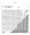
マクロブロックMB4には、動画撮影用の画素Aが、図6と同様に、例えば8画素×8画素=64画素存在する。このマクロブロックMB4の時間軸に従った移動量を撮像センサ11(図1)の二次元座標値で表すことによって、時間軸方向のすべてのマクロブロックの画像データを保存する必要がなく、座標値の変動量で表すことにより、動画像データの圧縮を行うことができる。
ここで、マクロブロックMB4は、動画撮影用の画素Aと共に、各画素Aに付随した静止画撮影用の画素Bが付随している。
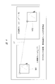
ここでは、図7に示すように、静止画撮影用の画素Bの縦方向および横方向共に4画素に1つの割合で、動画像撮影用の画素Aがある構成とする。ここで、静止画撮影用の画素Bは、例えばマクロブロックMB4の左上隅の画素A00に対して、4画素×4画素-1画素(画素A)=39画素の静止画撮影用の画素Bが、各動画撮影用の画素Aとの相対位置が固定された状態で付随している。
マクロブロックMB4の時間軸移動により、動画撮影用の画素Aは、Δtの時間経過後に、所定の座標に移動する。このとき、マクロブロックMB4の座標系内に含まれる静止画撮影用の画像B群も、同じ座標に一斉に移動する。
この動画撮影用の画像A群の時間軸に従った移動情報、すなわち図4において説明した時間軸変動差分情報に含まれる座標移動値を適用することで、静止画撮影用の画像B群も、動画撮影用の画像A群と同じフレームレートにて移動するとして、動画撮影用の画像A群と同じフレームレートで、静止画撮影用の画像B群のデータを生成することができる。
このとき、動画撮影用の画素Aは、図4の説明で記載した(6)、(7)のように、動画撮影用の画素Aにより構成されたマクロブロックの移動前と移動後の差分を圧縮符号化している。
この差分を動画撮影用の画像Aに付随する静止画撮影用の画素Bにそのまま適用することによって、高精細である画素Bも画素Aと同様に移動し、変化したという情報を圧縮符号化したデータに載せることができる。
〈動画像情報の生成例〉
図8は、図1の撮像センサ11により取得した情報から動画像の時間軸差分から、静止画像の時間軸圧縮情報を用いて動画像情報を生成する一例を示した説明図である。
図8は、図1の撮像センサ11により取得した情報から動画像の時間軸差分から、静止画像の時間軸圧縮情報を用いて動画像情報を生成する一例を示した説明図である。
図8において、マクロブロックMB5,MB6の形状、サイズ、および移動ベクトルVTなどの基本情報は、図4の説明と同一である。ここで、図8の左側に示す時刻tm=Tの8k画像フレームF1の座標上において、前述した動画撮影用の画像A群を含んだマクロブロックMB5は、動画撮影用の画像A群の近傍にある静止画撮影用の画像B群をも含んでいる。
これを時刻がΔt進んだ後の図8の右側に示す8k画像フレームF2では、図示した移動ベクトルにより、マクロブロックMB6に含まれる8k×1fps、すなわち静止画撮影用の画像B群も移動する。これにより、基の情報として、毎秒1フレーム(1fps)しか情報がない静止画撮影用の画像B群の、毎秒30フレーム(30fps)の高精細動画像として扱うことができる。
ここで、図4で説明したように、マクロブロックMB5の動画像用の画素Aは、マクロブロックMB6に移動したときに、その座標変化と共に、マクロブロックMB5とマクロブロックMB6との差分を、図4のマクロブロックMB1およびマクロブロックMB2との差分情報として有している。
これを基に静止画像用の画素Bも、マクロブロックMB5とマクロブロックMB6との間での差分を、その静止画像用の画素Bにそのまま差分付加することで、静止画像用の画素Bも時間軸圧縮を行うことができる。
ここで、マクロブロックMB5とマクロブロックMB6とが、マクロブロック単位以上の移動ではなく、例えばマクロブロックの半分の移動量で右に移動した場合、残りの半分の部分は、マクロブロックMB6ではカバーしていない。
これは、例えば基のマクロブロックMB5からマクロブロックMB6への時間軸差分を参照できた部分ではカバーできない。
しかし、例えばマクロブロックMB5の左にあったマクロブロックを用いてΔt進んだ後の画像全面を全スキャンし、もっとも相関が高い位置、すなわちマクロブロックMB6の左側のマクロブロックサイズ半分に相当する場所を、該マクロブロックMB5の左にあったマクロブロックでカバーすることができる。
このマクロブロックを構成する動画像用の画素Aに付随する静止画像用の画素Bも、前記したように動画像用の画素Aのマクロブロック間の差分と同じ差分を付加することで、動画像用の画素Aと静止画像用の画素Bとを含んだ、マクロブロックMB6および、その左にあるマクロブロックの情報を圧縮符号化して生成することができる。
なお、tm=Tのフレームとtm=T+Δtのフレームとが、ほぼすべてのマクロブロックで相関がないぐらい、大きく画像が変化した場合は、tm=T+Δtのフレームは、この時刻に撮影した動画像用の画素Aの全てを使って圧縮符号化、すなわちIピクチャを作るのとほぼ同じ工程を行うので、この場合は静止画像用の画素Bは情報が存在しない。
この場合は、かなり大きくデジタルカメラが振りまわされたようなブレを含んだ画像であるとして、動画像撮影用の画素Aから、各画素Aの間にある静止画像用の画素Bを補間作成することで、高精細動画像を得ることができる。
大きく手振れをしている状態の映像なので、元々ハイビジョンデジタルテレビの画素数で撮影している動画像撮影用の画素Aからの補間で、視覚的な不具合は問題にはならないと考えてよい。
〈高精細動画像の生成例〉
図9は、図1のデジタルカメラにより撮影した高精細動画像を生成する一例を示した説明図である。この図9では、図1の撮像センサ11により取得した2k×30fpsを時間軸圧縮して得られている動画像情報から、8k×1fpsの静止画像情報を処理して8k×30fpsの高精細動画像を生成する例を示している。
図9は、図1のデジタルカメラにより撮影した高精細動画像を生成する一例を示した説明図である。この図9では、図1の撮像センサ11により取得した2k×30fpsを時間軸圧縮して得られている動画像情報から、8k×1fpsの静止画像情報を処理して8k×30fpsの高精細動画像を生成する例を示している。
図9の右側に示す撮影した2k×30fpsの動画像は、複数の動画撮影用の画素Aによりフレームが構成され、このフレームが毎秒30枚の情報量として存在する。
これを図4に示したように、例えば30枚のうち1枚をIピクチャ、他をPピクチャ、Bピクチャとして、時間軸差分情報TDを生成して、離散コサイン変換およびハフマン符号化によりJPEG圧縮したIピクチャ(静止画)と、時間軸差分情報TDを2k×30fpsの動画像として取り扱う。
同じように撮影される高精細静止画である、図9の中央に示す8k×1fpsの画像は、毎秒1枚の静止画情報量として記録される。静止画像として保存する場合は、各々の静止画を、2k×30fpsのIピクチャと同様な、例えば離散コサイン変換およびハフマン符号化によりJPEG圧縮して保存される。
ここで、前記した時間軸差分情報TDを用いて、図9の中央に示す8k×1fpsの静止画像のフレーム間を時間軸補間TI1,TI2によって図9に示したような処理をすることで、図9の左側に示す8k×30fpsという高精細の動画像を得ることができる。
なお、ここで生成される8k画素の動画像は、2k画素と同じフレームレートを有する動画像であるが、出力する表示装置の能力次第では、さらに速いフレームレートでの再生が可能である。よって、生成された動画像を、時間軸フレーム間補間などの既存技術により、より速いフレームレートの動画像を生成して、保存、出力することも可能である。
同様に、出力する表示装置の能力次第では、生成された8k画素の動画像よりも更に多い画素数での再生が可能であるので、生成された動画像を画素間補間などの既存技術により、より多い画素数の動画像を生成して、保存、出力することも可能である。
〈静止画像データの生成例〉
図10は、図1のデジタルカメラにより撮影した情報から静止画像データを生成する一例を示した説明図である。なお、図10(a)は、前述した図3(b)と同じである。
図10は、図1のデジタルカメラにより撮影した情報から静止画像データを生成する一例を示した説明図である。なお、図10(a)は、前述した図3(b)と同じである。
図10(b)は、画素Aの位置が抜けた部分を、周辺の画素から補間計算し、画素B”を生成して、高精細静止画像の全画素を構築する例を示している。
画素B”の部分は補間計算のため、高精細静止画像の解像度は水平方向・垂直方向共に4画素に1つの割合で低下するが、撮影した画像は、離散コサイン変換によりJPEG圧縮される。そのため、撮像画像の基本的に周波数成分が最大限に高い場合を除けば、この補間計算を用いても画質が劣化することは少ない。
なお、デジタルスチルカメラの場合には、撮像センサの画素がある程度不良の画素が混入していても、それを補間処理して静止画像を作成することでカバーし、撮像センサの量産効率を上げているため、本実施の形態に示すような技術で画素補間を行っても、その影響は少なく、問題は起きない。
図10(c)は、画素Aの位置が抜けた部分を、図1のEVF25の表示用に読み出した画素Aを用いて高精細静止画像の全画素を構築する例を示している。この場合、例えば被写体が暗くて、画素Bはスローシャッタを切った場合でも、画素Aは感度を上げて短いシャッタ速度、具体的にはフレームレートである30fps=1/30秒以上の高速シャッタ速度にて取得している。そのため、両者のシャッタスピードに開きがあり、高精細静止画像の構築への適用には使えない場合が生じる。しかし、撮影条件が良くて、明るい条件では、画素Bのシャッタスピードも高速となるので、両者のシャッタスピードも近く、高精細静止画像の構築が可能となる。
〈デコーダの処理例〉
図11は、図1のデジタルカメラが有するエンコーダ/デコーダ14に設けられるデコーダ14aにおける処理の一例を示した説明図である。デコーダ14aは、第1~第3の伸長部を構成する。
図11は、図1のデジタルカメラが有するエンコーダ/デコーダ14に設けられるデコーダ14aにおける処理の一例を示した説明図である。デコーダ14aは、第1~第3の伸長部を構成する。
デコーダ14aは、前述したように2k×30fpsおよび8k×1fpsの静止画像情報を処理して、8k×30fpsの高精細動画像を生成する。
この図11においては、デコーダ14aの処理例として図9に示した動画像の処理を行う例について示している。
第1の圧縮画像データとなる8k×1fpsの画像P1は、メモリ16に保存されており、該メモリ16から毎秒1枚撮影された8kサイズの静止画像P2を取り出すことができる。この静止画像P2が第2の圧縮画像データとなる。
2k×30fpsの動画像P3は、メモリ15に保存されている。これら2種類の画像データは、図1で示したように、静止画像用と動画像用に分けられたそれぞれ異なるメモリ媒体に保存されてもよいが、同一のメモリ、特に着脱可能なメモリに両方の画像データが保存された状態でもよい。
メモリ15から読み出された2k×30fps動画像P3がデコーダ14aに入力されると、該デコーダ14aは、2k×30fps時間軸圧縮データとして(ステップS101)、前後をIフレームで挟まれた1つのブロックの間の全データをバッファする。
続いて、このデータを図5で説明した2k×30fpsのIピクチャと2k×30fpsのPピクチャ/Bピクチャに分割する(ステップS102)。これら2つのデータより、IピクチャとPピクチャ/Bピクチャの間の時間軸差分値を抽出し(ステップS103)、これを時間軸補間エンジンに入力する(ステップS104)。ここでは、2k動画像の図7における左上隅のA00 に位置する画像の1フレーム間の移動方向と距離を示す時間軸差分が上述した時間軸補間エンジンに入力される。
これに同期して、8k×1fps画像のIピクチャが時間軸補間エンジンに入力される(ステップS105,S104)。この8k×1fps画像が、前記した2k動画像の図7における左上隅のA00に位置する画像の1フレーム間の移動方向と距離を示す時間軸差分に応じて、画素A00に属する画素B群が、同じ移動方向と距離で移動する処理を行う。その結果8k×30fpsのPピクチャ/Bピクチャという高精細画像を2k動画像と同じフレームレートで生成する(ステップS106)。
そして、元データとなる8k×1fpsのIピクチャと整列することにより(ステップS107)、8k×30fpsの動画像が生成される(ステップS108)。生成された高精細高フレームレートの動画像は、図1のUSB端子18を介して外部機器への出力(ステップS109)、図1のHDMI端子17を介して外部のハイビジョン機器などへの出力(ステップS110)、あるいはSDカードスロットなどを介して着脱式外部メモリへの出力が行われる(ステップS111)。
なお、これらのインタフェースは、2k×30fpsの元撮影画像の出力にも利用されており、例えば出力先の対応状況に従って、2k×30fps動画像と8k×30fps動画像のいずれかを出力することを切り替えることができる(ステップS112)。
さらに、生成した8k×30fps動画像は、ステップS109,S111の処理を行う際には、改めて時間軸差分値を用いて、データ圧縮を行い、8kの画素を有する時間軸差分圧縮を行った画像データとして保存することも可能である。
以上により、高精細の8k画素Iピクチャ単位の静止画像およびそれより精細度の低い2k画素×30fpsの高速フレームレートの画像から、8k×30fpsの高精細、高速フレームレートの動画像を生成することができる。
それにより、静止画像撮影時におけるブロックアウトなどを防止しながら、EVF25や液晶ディスプレイ26における視認性、特に移動速度の速い被写体などの視認性を大幅に向上させることができ、デジタルカメラの付加価値を高めることができる。
以上、本発明者によってなされた発明を実施の形態に基づき具体的に説明したが、本発明は前記実施の形態に限定されるものではなく、その要旨を逸脱しない範囲で種々変更可能であることはいうまでもない。
なお、本発明は上記した実施の形態に限定されるものではなく、様々な変形例が含まれる。例えば、上記した実施の形態は本発明を分かりやすく説明するために詳細に説明したものであり、必ずしも説明した全ての構成を備えるものに限定されるものではない。
また、ある実施の形態の構成の一部を他の実施の形態の構成に置き換えることが可能であり、また、ある実施の形態の構成に他の実施の形態の構成を加えることも可能である。また、各実施の形態の構成の一部について、他の構成の追加、削除、置換をすることが可能である。
10 対物レンズ
11 撮像センサ
11a 画素
14 エンコーダ/デコーダ
14a デコーダ
15 メモリ
16 メモリ
17 HDMI端子
18 USB端子
20 ゲート
21 画素選択スイッチ
22 一時バッファ
25 電子ビューファインダ
26 液晶ディスプレイ
11 撮像センサ
11a 画素
14 エンコーダ/デコーダ
14a デコーダ
15 メモリ
16 メモリ
17 HDMI端子
18 USB端子
20 ゲート
21 画素選択スイッチ
22 一時バッファ
25 電子ビューファインダ
26 液晶ディスプレイ
Claims (10)
- 撮像面にアレイ状に配列された複数の画素に取り込まれた光学像を電気信号に変換する撮像センサと、
前記撮像センサが有する複数の前記画素のうち、第1の画素から読み出した電気信号をデジタル処理する第1の信号処理部と、
前記撮像センサが有する複数の前記画素のうち、第2の画素から読み出した電気信号をデジタル処理する第2の信号処理部と、
前記第1の信号処理部がデジタル処理した第1の画像データを表示する表示部と、
前記第1の信号処理部がデジタル処理した第1の画素数および第1のフレームレートを有する前記第1の画像データのフレーム間における相関性を利用して圧縮された第1の圧縮画像データを伸長する第1の伸長部と、
前記第1の圧縮画像データおよび第2の圧縮画像データに基づいて、前記第1の画像データのフレームレート以上の動画像を生成する第2の伸長部と、
前記第1の圧縮画像データおよび前記第2の圧縮画像データを保存するメモリ部と、
を有し、
前記第2の圧縮画像データは、前記第2の信号処理部がデジタル処理した前記第2の画素の画素数および前記第1のフレームレートより遅い第2のフレームレートを有する第2の画像データをフレーム内圧縮したデータであり、
前記第2の画素は、前記第1の画素よりも多い画素数である、撮像装置。 - 請求項1記載の撮像装置において、
前記第1の画像データは、デジタルテレビの動画像フォーマットにて規定されるフォーマットに一致する画素数を有する、撮像装置。 - 請求項1記載の撮像装置において、
前記第1の圧縮画像データおよび前記第2の圧縮画像データに基づいて、前記第2の画像データの画素数以上の動画像を生成する第3の伸長部を有する、撮像装置。 - 請求項1記載の撮像装置において、
前記第1の画素は、前記撮像面の横n(n≧2の整数)画素×縦m(m≧2の整数)画素に1つの割合で配置され、
前記第2の画素は、前記第1の画素を除いた画素である、撮像装置。 - 外部入力される第1の画素数および第1のフレームレートを有する第1の画像データのフレーム間における相関性を利用して圧縮された第1の圧縮画像データを伸長する第1の伸長部と、
前記第1の圧縮画像データおよび第2の圧縮画像データに基づいて、前記第1の画像データのフレームレート以上の動画像を生成する第2の伸長部と、
を有し、
前記第2の圧縮画像データは、第2の画素の画素数および前記第1のフレームレートより遅い第2フレームレートを有する第2の画像データをフレーム内圧縮したデータであり、
前記第2の画素は、前記第1の画素数より多い画素数である、画像処理装置。 - 請求項5記載の画像処理装置において、
前記第1の伸長部に入力される前記第1の画像データは、デジタルテレビの動画像フォーマットにて規定されるフォーマットに一致する画素数を有する、画像処理装置。 - 請求項5記載の画像処理装置において、
前記第1の圧縮画像データおよび前記第2の圧縮画像データに基づいて、前記第2の画像データの画素数以上の動画像を生成する第3の伸長部を有する、画像処理装置。 - 撮像面の横n(n≧2の整数)画素×縦m(m≧2の整数)画素に1つの割合で配置される第1の画素および前記第1の画素を除いた画素からなる第2の画素を備え、前記撮像面に照射された光学像を電気信号に変換する撮像センサと、
前記第1の画素から読み出した電気信号をデジタル処理する第1の信号処理部と、
前記第2の画素から読み出した電気信号をデジタル処理する第2の信号処理部と、
前記第1の信号処理部がデジタル処理した第1の画像データを表示する表示部と、
第1の圧縮画像データおよび第2の圧縮画像データに基づいて、第1の画像データのフレームレート以上の動画像を生成する伸長部と、
を有し、
前記伸長部は、前記第1の信号処理部がデジタル処理した前記第1の画像データを動画像として前記表示部に出力し、静止画像を撮影する際に、前記第2の信号処理部がデジタル処理した第2の画像データを読み出して、第1の画像データのフレームレートと同じまたはそれ以上のフレームレートを有する動画像を生成して出力する、デジタルカメラ。 - 請求項8記載のデジタルカメラにおいて、
前記第1の画像データは、デジタルテレビの動画像フォーマットにて規定されるフォーマットに一致する画素数を有する、デジタルカメラ。 - 請求項8記載のデジタルカメラにおいて、
前記第1の圧縮画像データおよび前記第2の圧縮画像データに基づいて、前記第2の画像データの画素数以上の動画像を生成する第3の伸長部を有する、デジタルカメラ。
Priority Applications (1)
| Application Number | Priority Date | Filing Date | Title |
|---|---|---|---|
| PCT/JP2015/058769 WO2016151734A1 (ja) | 2015-03-23 | 2015-03-23 | 撮像装置、画像処理装置、およびデジタルカメラ |
Applications Claiming Priority (1)
| Application Number | Priority Date | Filing Date | Title |
|---|---|---|---|
| PCT/JP2015/058769 WO2016151734A1 (ja) | 2015-03-23 | 2015-03-23 | 撮像装置、画像処理装置、およびデジタルカメラ |
Publications (1)
| Publication Number | Publication Date |
|---|---|
| WO2016151734A1 true WO2016151734A1 (ja) | 2016-09-29 |
Family
ID=56977976
Family Applications (1)
| Application Number | Title | Priority Date | Filing Date |
|---|---|---|---|
| PCT/JP2015/058769 Ceased WO2016151734A1 (ja) | 2015-03-23 | 2015-03-23 | 撮像装置、画像処理装置、およびデジタルカメラ |
Country Status (1)
| Country | Link |
|---|---|
| WO (1) | WO2016151734A1 (ja) |
Citations (3)
| Publication number | Priority date | Publication date | Assignee | Title |
|---|---|---|---|---|
| JP2005318548A (ja) * | 2004-03-30 | 2005-11-10 | Masahiko Yanaida | 撮像システム、画像データ列作成装置、画像生成装置、画像データ列生成装置、画像データ列生成システム、及び画像伝送システム |
| JP3934151B2 (ja) * | 2005-06-22 | 2007-06-20 | 松下電器産業株式会社 | 画像生成装置および画像生成方法 |
| JP2011055278A (ja) * | 2009-09-02 | 2011-03-17 | Sharp Corp | 動き情報取得装置及び画像処理装置 |
-
2015
- 2015-03-23 WO PCT/JP2015/058769 patent/WO2016151734A1/ja not_active Ceased
Patent Citations (3)
| Publication number | Priority date | Publication date | Assignee | Title |
|---|---|---|---|---|
| JP2005318548A (ja) * | 2004-03-30 | 2005-11-10 | Masahiko Yanaida | 撮像システム、画像データ列作成装置、画像生成装置、画像データ列生成装置、画像データ列生成システム、及び画像伝送システム |
| JP3934151B2 (ja) * | 2005-06-22 | 2007-06-20 | 松下電器産業株式会社 | 画像生成装置および画像生成方法 |
| JP2011055278A (ja) * | 2009-09-02 | 2011-03-17 | Sharp Corp | 動き情報取得装置及び画像処理装置 |
Similar Documents
| Publication | Publication Date | Title |
|---|---|---|
| JP5189109B2 (ja) | 改善された時間サンプリングを提供するデジタルカメラ | |
| US8264565B2 (en) | Image processing device and image processing method | |
| KR101913837B1 (ko) | 파노라마 영상 생성 방법 및 이를 적용한 영상기기 | |
| JP4525561B2 (ja) | 撮像装置、画像処理方法、並びにプログラム | |
| US20080273094A1 (en) | Imaging apparatus and control method therefor | |
| JP2010233028A (ja) | 動画記録装置、及び動画像の傾き補正方法、プログラム | |
| JP4605217B2 (ja) | 撮影装置及びそのプログラム | |
| JP6702792B2 (ja) | 画像処理装置およびその制御方法 | |
| CN113556462B (zh) | 用于控制平移倾斜变焦相机的方法和系统以及存储介质 | |
| JP2021118403A (ja) | 画像処理装置、その制御方法、プログラム並びに画像処理システム | |
| JP4887750B2 (ja) | 画像処理装置、制御方法及びプログラム | |
| JP6351212B2 (ja) | 撮像装置、撮像装置の制御方法及びシステム | |
| JP2014053857A (ja) | 画像処理装置、撮像装置及び画像処理プログラム | |
| JP2007135135A (ja) | 動画像撮像装置 | |
| CN104869307A (zh) | 一种拍摄的方法和装置 | |
| WO2016151734A1 (ja) | 撮像装置、画像処理装置、およびデジタルカメラ | |
| CN112422782B (zh) | 显示控制设备及其控制方法和计算机可读存储介质 | |
| JP6351213B2 (ja) | 撮像装置、撮像装置の制御方法及びシステム | |
| JP5655589B2 (ja) | 撮像装置 | |
| JP5167229B2 (ja) | 画像撮像装置 | |
| JP6594485B2 (ja) | 撮像装置、撮像装置の制御方法及びシステム | |
| JP6602425B2 (ja) | 撮像装置、撮像装置の制御方法及びシステム | |
| JP2009038627A (ja) | 撮像装置 | |
| JP2018088600A (ja) | 画像処理装置、画像処理方法及びプログラム | |
| US20250104293A1 (en) | Image processing system, control method, and storage medium |
Legal Events
| Date | Code | Title | Description |
|---|---|---|---|
| 121 | Ep: the epo has been informed by wipo that ep was designated in this application |
Ref document number: 15886289 Country of ref document: EP Kind code of ref document: A1 |
|
| NENP | Non-entry into the national phase |
Ref country code: DE |
|
| NENP | Non-entry into the national phase |
Ref country code: JP |
|
| 122 | Ep: pct application non-entry in european phase |
Ref document number: 15886289 Country of ref document: EP Kind code of ref document: A1 |