WO2016147785A1 - 冷媒圧縮装置および冷凍サイクル装置 - Google Patents
冷媒圧縮装置および冷凍サイクル装置 Download PDFInfo
- Publication number
- WO2016147785A1 WO2016147785A1 PCT/JP2016/054603 JP2016054603W WO2016147785A1 WO 2016147785 A1 WO2016147785 A1 WO 2016147785A1 JP 2016054603 W JP2016054603 W JP 2016054603W WO 2016147785 A1 WO2016147785 A1 WO 2016147785A1
- Authority
- WO
- WIPO (PCT)
- Prior art keywords
- refrigerant
- rotary
- bottom plate
- rotary compressors
- connecting portion
- Prior art date
- Legal status (The legal status is an assumption and is not a legal conclusion. Google has not performed a legal analysis and makes no representation as to the accuracy of the status listed.)
- Ceased
Links
Images


Classifications
-
- F—MECHANICAL ENGINEERING; LIGHTING; HEATING; WEAPONS; BLASTING
- F04—POSITIVE - DISPLACEMENT MACHINES FOR LIQUIDS; PUMPS FOR LIQUIDS OR ELASTIC FLUIDS
- F04B—POSITIVE-DISPLACEMENT MACHINES FOR LIQUIDS; PUMPS
- F04B39/00—Component parts, details, or accessories, of pumps or pumping systems specially adapted for elastic fluids, not otherwise provided for in, or of interest apart from, groups F04B25/00 - F04B37/00
-
- F—MECHANICAL ENGINEERING; LIGHTING; HEATING; WEAPONS; BLASTING
- F04—POSITIVE - DISPLACEMENT MACHINES FOR LIQUIDS; PUMPS FOR LIQUIDS OR ELASTIC FLUIDS
- F04C—ROTARY-PISTON, OR OSCILLATING-PISTON, POSITIVE-DISPLACEMENT MACHINES FOR LIQUIDS; ROTARY-PISTON, OR OSCILLATING-PISTON, POSITIVE-DISPLACEMENT PUMPS
- F04C29/00—Component parts, details or accessories of pumps or pumping installations, not provided for in groups F04C18/00 - F04C28/00
-
- F—MECHANICAL ENGINEERING; LIGHTING; HEATING; WEAPONS; BLASTING
- F25—REFRIGERATION OR COOLING; COMBINED HEATING AND REFRIGERATION SYSTEMS; HEAT PUMP SYSTEMS; MANUFACTURE OR STORAGE OF ICE; LIQUEFACTION SOLIDIFICATION OF GASES
- F25B—REFRIGERATION MACHINES, PLANTS OR SYSTEMS; COMBINED HEATING AND REFRIGERATION SYSTEMS; HEAT PUMP SYSTEMS
- F25B1/00—Compression machines, plants or systems with non-reversible cycle
- F25B1/04—Compression machines, plants or systems with non-reversible cycle with compressor of rotary type
Definitions
- Embodiments of the present invention relate to a refrigerant compression apparatus and a refrigeration cycle apparatus having a plurality of vertical rotary compressors.
- Refrigeration cycle devices are known in which two vertical rotary compressors are connected in parallel to a circulation circuit through which refrigerant circulates. Since the rotary compressor is vibrated during operation, in the conventional refrigeration cycle apparatus, an anti-vibration rubber is interposed between the lower end portion of the rotary compressor and the bottom plate of the casing. The anti-vibration rubber absorbs the vibration of the rotary compressor.
- the two rotary compressors adjacent on the bottom plate have their discharge sides connected to each other via a refrigerant pipe.
- the refrigerant pipe is drawn out from the upper part of the rotary compressor around the rotary compressor.
- An object of the present invention is to obtain a refrigerant compression device and a refrigeration cycle device that can suppress vibration transmitted to piping during operation of a rotary compressor.
- the refrigerant compression device includes a housing, a plurality of vertical rotary compressors, a vibration isolator, a pipe, a first connection portion, and a second connection portion.
- the rotary compressor is provided on the bottom plate of the casing.
- the vibration isolator is interposed between the rotary compressor and the bottom plate, and elastically supports the rotary compressor on the bottom plate.
- the said piping is connected to the upper part of each said rotary compressor.
- the first connecting portion is connected to upper portions of the plurality of rotary compressors.
- the second connecting portion rigidly fixes the upper portions of the plurality of rotary compressors to the casing in cooperation with the first connecting portion.
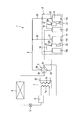
- FIG. 1 is a circuit diagram of the refrigeration cycle apparatus according to the first embodiment.
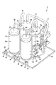
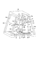
- FIG. 2 is a perspective view of the refrigerant compression device showing a state in which two rotary compressors with suction cups are installed on a bottom plate together with an accumulator in the first embodiment.
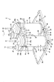
- FIG. 3 is a perspective view of the refrigerant compression apparatus showing a state in which upper portions of two rotary compressors each having a suction cup are connected by a connecting body in the first embodiment.
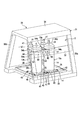
- FIG. 4 is a perspective view of the refrigerant compression device showing a state in which the upper parts of two rotary compressors provided with suction cups are fixed to a housing via a connecting body in the first embodiment.
- FIG. 1 is a circuit diagram of the refrigeration cycle apparatus according to the first embodiment.
- FIG. 2 is a perspective view of the refrigerant compression device showing a state in which two rotary compressors with suction cups are installed on a bottom plate together with an accumulator in the first embodiment.
- FIG. 3 is
- FIG. 5 is a side view of the refrigerant compression device showing a state in which the upper part of the rotary compressor provided with the suction cup is fixed to the housing via a connecting body in the first embodiment.
- FIG. 6 is a side view of the refrigerant compression device showing a state in which the upper part of the rotary compressor and the upper part of the accumulator attached to the suction cup are fixed to the housing via a connecting body in the second embodiment.
- FIG. 7 is a perspective view of the refrigerant compression device showing a state in which upper portions of two rotary compressors provided with suction cups are fixed to a housing via a connecting body in the second embodiment.
- FIG. 1 is a circuit diagram showing a refrigeration cycle apparatus 1 used in, for example, a chilling unit.
- the refrigeration cycle apparatus 1 includes a refrigerant compression device 2, a four-way valve 3, an air heat exchanger 4, an expansion valve 5, a receiver tank 6, and a water heat exchanger 7 as main elements.
- the plurality of elements constituting the refrigeration cycle apparatus 1 are connected via a circulation circuit 8 in which the refrigerant circulates.
- the refrigerant compressor 2 includes two rotary compressors 11a and 11b. Suction devices including suction cups 12a and 12b and accumulators 13a and 13b are attached to the suction sides of the rotary compressors 11a and 11b, respectively.
- the rotary compressor 11 a of this embodiment is a vertical rotary compressor and includes a cylindrical sealed container 14.
- the sealed container 14 accommodates the compression mechanism unit 15.
- the compression mechanism unit 15 has two cylinders 16a and 16b arranged in the axial direction of the sealed container 14, and rollers (not shown) are accommodated in the cylinders 16a and 16b.
- the roller revolves in each of the cylinders 16a and 16b when receiving torque from the motor 17.
- the volume of the compression chamber formed in each cylinder 16a, 16b changes, and the refrigerant
- the rotational speeds of the two rotary compressors 11a and 11b may be the same or different from each other.
- the rotational directions of the rotors of the two rotary compressors 11a and 11b may be the same or opposite.
- the suction sides of the suction cups 12a and 12b are connected to the discharge sides of the accumulators 13a and 13b via first suction pipes 19, respectively.
- the discharge sides of the suction cups 12a and 12b are connected to the suction ports of the rotary compressors 11a and 11b through two second suction pipes 20, respectively.
- the rotary compressors 11a and 11b each have a discharge port 21 formed in the upper part of the sealed container 14.
- the discharge port 21 is connected to the first port 3 a of the four-way valve 3 through a discharge pipe 22 that constitutes a part of the circulation circuit 8.
- the second port 3 b of the four-way valve 3 is connected to the air heat exchanger 4.
- the air heat exchanger 4 is connected to the upstream end of the refrigerant flow path 7 a of the water heat exchanger 7 via the expansion valve 5 and the receiver tank 6.
- the water heat exchanger 7 has a water flow path 7b for exchanging heat with the refrigerant flow path 7a.
- a water pipe 23 is connected to the water flow path 7 b of the water heat exchanger 7.
- the upstream end of the water pipe 23 is connected to a water supply source.
- the downstream end of the water pipe 23 is connected to, for example, a hot water storage tank, a hot water tap or an air conditioning device.
- the downstream end of the refrigerant flow path 7 a of the water heat exchanger 7 is connected to the third port 3 c of the four-way valve 3.
- the fourth port 3d of the four-way valve 3 is connected to the suction side of each accumulator 13a, 13b.
- the four-way valve 3 When the refrigeration cycle apparatus 1 operates in the cooling mode, the four-way valve 3 includes a first port 3a communicating with the second port 3b and a third port 3c connected to the fourth port 3d, as shown by a solid line in FIG. It has been switched to communicate.
- the low-temperature and low-pressure gas-phase refrigerant is compressed by the two rotary compressors 11a and 11b and discharged as a high-pressure gas-phase refrigerant having a high degree of superheat. It is discharged from the outlet 21 to the circulation circuit 8.
- the high-temperature and high-pressure gas-phase refrigerant discharged from the discharge port 21 is guided to the air heat exchanger 4 functioning as a condenser via the four-way valve 3.
- the gas-phase refrigerant guided to the air heat exchanger 4 is condensed by heat exchange with the air and changed into a high-pressure liquid-phase refrigerant.
- the high-pressure liquid-phase refrigerant is depressurized in the process of passing through the expansion valve 5, and changes to an intermediate-pressure gas-liquid two-phase refrigerant.
- the gas-liquid two-phase refrigerant is guided to the refrigerant flow path 7a of the water heat exchanger 7 via the receiver 6, and exchanges heat with water flowing through the water flow path 7b in the process of passing through the refrigerant flow path 7a. That is, the water heat exchanger 7 functions as an evaporator.
- the gas-liquid two-phase refrigerant flowing through the refrigerant flow path 7a evaporates and receives heat from the water in the water flow path 7b, and changes into a low-temperature and low-pressure gas-liquid two-phase refrigerant due to latent heat of evaporation.
- the water in the water flow path 7b is cooled by removing the latent heat, and is converted into cold water, for example, to air conditioning equipment.
- the low-temperature and low-pressure gas-liquid two-phase refrigerant that has passed through the water heat exchanger 7 is guided to the accumulators 13a and 13b via the four-way valve 3, where it is separated into a liquid-phase refrigerant and a gas-phase refrigerant. Further, the gas-phase refrigerant separated from the liquid-phase refrigerant is guided to the suction cups 12 a and 12 b through the first suction pipe 19 that constitutes a part of the circulation circuit 8. In the suction cups 12a and 12b, a small amount of liquid-phase refrigerant that cannot be separated by the accumulators 13a and 13b is separated from the gas-phase refrigerant.
- the low-temperature and low-pressure gas-phase refrigerant accumulated in the suction cups 12a and 12b is returned to the cylinders 16a and 16b of the rotary compressors 11a and 11b via the second suction pipe 20 constituting a part of the circulation circuit 8. It is.
- the low-temperature and low-pressure gas-phase refrigerant returned to the cylinders 16a and 16b again becomes a high-temperature gas-phase refrigerant having a high degree of superheat and is discharged from the rotary compressors 11a and 11b to the circulation circuit 8.
- the four-way valve 3 is connected to the third port 3c and the second port 3b is connected to the fourth port, as indicated by a broken line in FIG. It is switched to communicate with 3d.
- the high-temperature and high-pressure gas-phase refrigerant discharged from the rotary compressors 11a and 11b flows through the four-way valve 3 to the refrigerant flow of the water heat exchanger 7.
- Heat is exchanged with water flowing through the water flow path 7b in the process of being guided to the path 7a and flowing through the refrigerant flow path 7a. That is, the water heat exchanger 7 functions as a condenser.
- the gas-phase refrigerant flowing through the refrigerant flow path 7a is condensed by exchanging heat with the water flowing through the water flow path 7b, and changed into a high-pressure liquid-phase refrigerant.
- the water in the water flow path 7b is heated by receiving the heat of the gas-phase refrigerant and becomes warm water, for example, sent to an air conditioning device.
- the high-temperature liquid-phase refrigerant that has passed through the water heat exchanger 7 is guided to the expansion valve 5 via the receiver 6.
- the high-temperature liquid-phase refrigerant is depressurized in the process of passing through the expansion valve 5 and is changed to an intermediate-pressure gas-liquid two-phase refrigerant.
- the gas-liquid two-phase refrigerant is guided to the air heat exchanger 4 functioning as an evaporator, and evaporates by exchanging heat with the air here to be changed into a low-temperature and low-pressure gas-liquid two-phase refrigerant.
- the low-temperature and low-pressure gas-liquid two-phase refrigerant that has passed through the air heat exchanger 4 is guided to the accumulators 13 a and 13 b via the four-way valve 3.
- the low-temperature and low-pressure gas-liquid two-phase refrigerant is separated into a liquid-phase refrigerant and a gas-phase refrigerant by the accumulators 13a and 13b, as in the cooling mode. Further, a small amount of liquid phase refrigerant that could not be separated by the accumulators 13a and 13b is separated from the gas phase refrigerant by the suction cups 12a and 12b.
- the low-temperature and low-pressure gas-phase refrigerant accumulated in the suction cups 12a and 12b is returned to the cylinders 16a and 16b of the rotary compressors 11a and 11b via the second suction pipe 20.
- the housing 30 As shown in FIGS. 4 and 5, the rotary compressors 11a and 11b, the suction cups 12a and 12b, and the accumulators 13a and 13b are supported by a rigid housing 30 made of metal.
- the housing 30 according to this embodiment includes a main frame 31 and a sub frame 32.
- the main frame 31 includes a rectangular frame-shaped lower structure 33, a rectangular upper structure 34, four vertical bars 35a, 35b, 35c, and 35d and a bottom plate 36 as main elements.
- the vertical bars 35 a, 35 b, 35 c, and 35 d stand so as to connect the four corners of the lower structure 33 and the four corners of the upper structure 34.
- the vertical bars 35 a and 35 b and the vertical bars 35 c and 35 d facing in the depth direction of the main frame 31 are inclined so as to approach each other as they move upward of the main frame 31. Therefore, the main frame 31 is formed in a tapered shape in which the depth dimension decreases from the lower structure 33 toward the upper structure 34.
- the bottom plate 36 is, for example, a square dish-like element, and is fixed on the lower structure 33 by means such as welding or bolting.
- the bottom plate 36 forms a machine room 37 between the upper structure 34.
- the machine room 37 is surrounded by vertical bars 35a, 35b, 35c, and 35d.
- the main frame 31 is not limited to a tapered shape, and may be, for example, a square box shape, and there is no particular limitation on the shape or structure thereof.
- the subframe 32 is configured by an elongated flat plate extending in the width direction of the housing 30.
- One end of the subframe 32 is integrally coupled to an intermediate portion along the height direction of the vertical bar 35a by means such as welding or bolting.
- the other end of the sub frame 32 is integrally coupled to an intermediate portion along the height direction of the vertical bar 35c by means such as welding or bolting. For this reason, the sub-frame 32 is spanned horizontally between the vertical beam 35a and the vertical beam 35c.
- the rotary compressors 11a and 11b, the suction cups 12a and 12b, and the accumulators 13a and 13b are accommodated in a machine room 37 of the housing 30.
- the hermetic containers 14 of the rotary compressors 11 a and 11 b are supported on the bottom plate 36 in a vibration-proof manner so as to be aligned along the subframe 32.
- a plurality of leg portions 40 are fixed to the lower end portion of the sealed container 14.
- the leg portion 40 projects radially around the lower end of the sealed container 14.
- a cylindrical vibration isolator 41 is interposed between the tip of each leg 40 and the bottom plate 36.
- the vibration isolator 41 is formed of a viscoelastic body such as rubber or a synthetic resin material, for example.
- the tip of each leg 40 is coupled to the bottom plate 36 via a bolt 42 that penetrates the vibration isolator 41.
- the vibration isolator 41 is compressed between the front end portion of the leg portion 40 and the bottom plate 36 to elastically support the lower end portion of the sealed container 14.
- the discharge ports 21 of the rotary compressors 11a and 11b protrude upward from the upper end of the hermetic container 14.
- the discharge pipe 22 connected to the discharge port 21 is led upward above the sealed container 14 and then turned downward while drawing a smooth arc and is routed on the bottom plate 36 through the side of the sealed container 14. ing.
- the suction cups 12a and 12b are respectively cylindrical elements, and are arranged behind the hermetic containers 14 of the rotary compressors 11a and 11b in a vertically installed posture. Each suction cup 12a, 12b is supported by the hermetic container 14 via a coupling band 44 shown in FIG.
- the coupling band 44 is an element obtained by processing a band-shaped metal plate into an annular shape, and is wound around an outer peripheral surface of an intermediate portion along the height direction of the suction cups 12a and 12b. Furthermore, the flange part 45 which protrudes toward the outer side along the radial direction of the suction cups 12a and 12b is formed in the both ends of the coupling band 44. As shown in FIG. The flange portion 45 is fixed to a holder 46 protruding from the outer peripheral surface of the sealed container 14 by means such as screwing.
- the suction cups 12a and 12b are attached to the hermetic container 14 at a position away from the bottom plate 36, and the two second suction pipes 20 are connected to the bottoms of the suction cups 12a and 12b. ing.
- the second suction pipe 20 is guided to the side surface of the bottom portion of the sealed container 14 through a space formed between the suction cups 12a and 12b and the bottom plate 36.
- the suction cups 12 a and 12 b have a refrigerant inlet 47.
- the refrigerant inlet 47 protrudes upward from the upper ends of the suction cups 12 a and 12 b, and the first suction pipe 19 is connected to the refrigerant inlet 47.
- the accumulators 13a and 13b are cylindrical elements, and are supported directly on the bottom plate 36 in a vertically installed posture.
- the accumulators 13a and 13b are located behind the sealed container 14 of the rotary compressors 11a and 11b. Therefore, in this embodiment, the suction cups 12a and 12b are located between the accumulators 13a and 13b and the rotary compressors 11a and 11b.
- a first suction pipe 19 connecting the suction cups 12a, 12b and the accumulators 13a, 13b is curved in an arc shape above the suction cups 12a, 12b and the accumulators 13a, 13b, and the second suction pipe 19 It is accommodated in the machine room 37 together with the pipe 20.
- connection body 50 of this embodiment includes a pair of connection bands 51 and 52 and a bracket 53.
- the connection bands 51 and 52 are an example of a first connection part
- the bracket 53 is an example of a second connection part.
- the connecting bands 51 and 52 are elements obtained by processing a band-shaped metal plate into an annular shape, and have a first annular portion 54a and a second annular portion 54b.
- the first annular portion 54a and the second annular portion 54b are connected so as to be adjacent to each other.
- the first annular portion 54a of the connection band 51 is connected to the upper portion of the hermetic container 14 by, for example, wrapping around the outer peripheral surface of the hermetic container 14 of one rotary compressor 11a.
- the first annular portion 54a supports the sealed container 14 at a position above the center of gravity of the rotary compressor 11a.
- the second annular portion 54b of the connection band 51 is wound around the outer peripheral surface of the suction cup 12a attached to one rotary compressor 11a.
- the second annular portion 54 b supports the suction cup 12 a at a position above the center of gravity of the suction cup 12 a and is positioned above the coupling band 44.
- first annular portion 54a of the connecting band 52 is connected to the upper portion of the sealed container 14 by, for example, winding it around the outer peripheral surface of the sealed container 14 of the other rotary compressor 11b.
- the first annular portion 54a supports the sealed container 14 at a position above the center of gravity of the rotary compressor 11b.
- the second annular portion 54b of the connecting band 52 is wound around the outer peripheral surface of the suction cup 12b attached to the other rotary compressor 11b.
- the second annular portion 54b supports the suction cup 12a at a position above the center of gravity of the suction cup 12b.
- the bracket 53 of the coupling body 50 is a block-like element, and is formed of a metal material such as an aluminum alloy.
- the bracket 53 is coupled to the coupling bands 51 and 52 so as to be positioned between the first annular portion 54 a of the coupling band 51 and the first annular portion 54 a of the coupling band 52. For this reason, the bracket 53 is sandwiched between the upper parts of the sealed containers 14 of the two rotary compressors 11a and 11b, and defines the interval between the upper parts of the sealed containers 14.
- the bracket 53 is adjacent to the subframe 32 of the housing 30.
- the bracket 53 has a fixed surface 56 that faces the subframe 32.
- a plurality of screw holes 57 are formed in the fixed surface 56.
- the bracket 53 of the connecting body 50 is rigidly attached to the rigid housing 30 at the upper part of the two rotary compressors 11a and 11b provided with the suction cups 12a and 12b in cooperation with the connecting bands 51 and 52. It is fixed.
- the rotary compressors 11a and 11b are elastically supported on the bottom plate 36 via the vibration isolator 41, the rotary compressors 11a and 11b are in operation. Can be absorbed by the vibration isolator 41.
- the two rotary compressors 11 a and 11 b are connected to each other via the connection bands 51 and 52 of the connection body 50 and the bracket 53 at the upper part of the sealed container 14 away from the vibration isolation body 41. Is rigidly fixed to the sub-frame 32 of the housing 30. For this reason, the two rotary compressors to which the discharge pipe 22 is connected although the lower ends of the rotary compressors 11a and 11b are floatingly supported by the bottom plate 32 via the vibration isolator 41. It can avoid that the upper part of 11a, 11b vibrates with a big amplitude individually.
- the upper portions of the suction cups 12a and 12b to which the first suction pipe 19 is connected are rigidly fixed to the subframe 32 via the connection bands 51 and 52 of the connection body 50 and the bracket 53. Yes. Therefore, it can avoid that the upper part of the suction cups 12a and 12b receives the vibration of the sealed container 14 and vibrates with a large amplitude.
- [Second Embodiment] 6 and 7 disclose a second embodiment.
- the configuration of the connecting body 70 is different from that of the first embodiment, and the configuration of the refrigerant compression device 2 other than that is the same as that of the first embodiment. Therefore, in the second embodiment, the same components as those in the first embodiment are denoted by the same reference numerals, and the description thereof is omitted.
- the connecting body 70 is formed of a single metal plate that has been subjected to sheet metal pressing.
- the connecting body 70 includes a first connecting portion 71 and a second connecting portion 72.
- the first connecting portion 71 is a first supporting portion 73 that supports the two rotary compressors 11a and 11b, and a second supporting portion that supports the two suction cups 12a and 12b and the two accumulators 13a and 13b.
- the support part 74 is provided.
- the second connecting portion 72 has a pair of fixing portions 75 a and 75 b fixed to the housing 30.
- fixed part 75a, 75b are the integral structures which continued mutually.
- the pair of fixing portions 75a and 75b are each formed in a flat plate shape.
- One fixing portion 75a is fixed to the vertical bars 35a and 35c by means such as screwing or welding so as to straddle between the upper parts of the vertical bars 35a and 35c.
- the other fixing part 75b is fixed to the vertical bars 35b and 35d by means such as screwing or welding so as to straddle between the upper parts of the vertical bars 35b and 35d.
- the first support portion 73 and the second support portion 74 are horizontally disposed so as to be parallel to the bottom plate 36 between the fixing portions 75a and 75b.
- the 1st support part 73 has a pair of 1st fitting holes 76 with which the upper part of the airtight container 14 of rotary compressor 11a, 11b fits.
- the upper part of the sealed container 14 is preferably connected to the opening edge of the first fitting hole 76 by means such as screwing or bonding.
- the first support portion 73 supports the upper portion of the hermetic container 14 at a position higher than the center of gravity of the rotary compressors 11a and 11b.
- the location where the first support portion 73 supports the sealed container 14 coincides with the location where the rotary compressors 11a and 11b resonate.
- the second support portion 74 has a pair of second fitting holes 77 into which the suction cups 12a, 12b are fitted and a pair of third fitting holes 78 into which the accumulators 13a, 13b are fitted.
- the suction cups 12a and 12b are preferably connected to the opening edge of the second fitting hole 77 by means such as screwing or bonding.
- the accumulators 13a and 13b are desirably connected to the opening edge of the third fitting hole 78 by means such as screwing or bonding.
- the second support portion 74 supports the suction cups 12a and 12b and the accumulators 13a and 13b at positions higher than the center of gravity of the suction cups 12a and 12b and the accumulators 13a and 13b.
- the locations where the second support 74 supports the suction cups 12a, 12b and the accumulators 13a, 13b coincide with the locations where the suction cups 12a, 12b and the accumulators 13a, 13b resonate.
- the height dimension L1 from the location where the rotary compressors 11a, 11b resonate to the bottom plate 36 is the height dimension from the location where the suction cups 12a, 12b and the accumulators 13a, 13b resonate to the bottom plate 36. Greater than L2.
- a step S along the height direction of the housing 30 is formed between the first support portion 73 and the second support portion 74.
- the two rotary compressors 11a and 11b are connected to each other via the first connecting portion 71 of the connecting body 70 at the upper part of the hermetic container 14 away from the vibration isolator 41,
- the second connecting portion 72 of the connecting body 70 is rigidly fixed to the vertical bars 35a, 35b, 35c, 35d of the housing 30.
- the suction cups 12 a and 12 b attached to the sealed container 14 and the accumulators 13 a and 13 b directly attached on the bottom plate 36 are rigidly attached to the housing 30 through the coupling body 70. It is fixed. Therefore, it is possible to avoid the upper portions of the suction cups 12a and 12b and the upper portions of the accumulators 13a and 13b from vibrating with large amplitude due to the vibrations of the rotary compressors 11a and 11b.
- the two rotary compressors 11a and 11b, the two suction cups 12a and 12b, and the two accumulators 13a and 13b are combined using one connecting body 70 that has been subjected to sheet metal pressing.
- the upper parts of the rotary compressors 11a and 11b, the suction cups 12a and 12b, and the accumulators 13a and 13b can be rigidly fixed to the housing 30 in a lump.
- casing 30 can be simplified, and the refrigerant
- the rotary compressors 11a and 11b, the suction cups 12a and 12b, and the accumulators 13a and 13b having different resonance locations are fixed to the housing 30 with a single connecting body 70, the rotary compressors 11a and 11b, The resonance generated between the suction cups 12a and 12b and the accumulators 13a and 13b can be moved to a high frequency range.
- connection bands 51 and 52 as the first connection portions are individually wound around the upper portions of the rotary compressors 11a and 11b, and the bracket 53 as the second connection portion is connected to the connection bands 51 and 52.
- the upper parts of the rotary compressors 11a and 11b are rigidly fixed to the subframe 32 in cooperation with the above, but the configuration of the connecting body 50 is not limited to this.
- the upper parts of the rotary compressors 11a and 11b are connected to each other by connecting bands 51 and 52 as first connecting parts, and are connected to each other using a bracket 53 as a second connecting part.
- the upper part of at least one of the compressors 11a and 11b and the subframe 32 may be firmly coupled.
- the rotary compressor is not limited to a vertical rotary compressor, and can be similarly implemented with a vertical scroll compressor.
- the number of rotary compressors is not limited to two, but may be three.
- the bracket of the connecting member is fixed to the subframe of the housing with a plurality of bolts, but the bracket may be fixed to the subframe by other means such as adhesion, brazing, or welding. Good.
- the connecting band and the bracket are configured as separate elements.
- the connecting band and the bracket may be integrated.
- the casing may be formed into a box shape by combining a plurality of panels, for example, and the connecting member may be fixed to one panel of the casing.
Landscapes
- Engineering & Computer Science (AREA)
- Mechanical Engineering (AREA)
- General Engineering & Computer Science (AREA)
- Physics & Mathematics (AREA)
- Thermal Sciences (AREA)
- Applications Or Details Of Rotary Compressors (AREA)
- Compressor (AREA)
Abstract
冷媒圧縮装置(2)は、底板(36)を有する筐体(30)と、底板(36)の上に併設された複数の縦形の回転式圧縮機(11a, 11b)と、回転式圧縮機(11a, 11b)を底板(36)の上に弾性的に支持する防振体(41)と、各回転式圧縮機(11a, 11b)の上部に接続された配管(22)と、複数の回転式圧縮機(11a, 11b)の上部に連結された第1の連結部(51, 52, 71)と、第1の連結部(51, 52, 71)と協働して複数の回転式圧縮機(11a, 11b)の上部を筐体(30)にリジッドに固定する第2の連結部(53, 72)と、を備えている。
Description
本発明の実施形態は、複数の縦形の回転式圧縮機を有する冷媒圧縮装置および冷凍サイクル装置に関する。
冷媒が循環する循環回路に、二台の縦型の回転式圧縮機を並列に接続した冷凍サイクル装置が知られている。回転式圧縮機は、運転中に振動を伴うので、従来の冷凍サイクル装置では、回転式圧縮機の下端部と筐体の底板との間に防振ゴムが介在されている。防振ゴムは、回転式圧縮機の振動を吸収する。
さらに、底板の上で隣り合う二台の回転式圧縮機は、その吐出側が冷媒配管を介して互いに接続されている。冷媒配管は、回転式圧縮機の上部から回転式圧縮機の周囲に引き出されている。
従来の冷凍サイクル装置によると、回転式圧縮機は、その下端部が防振ゴムを介して筐体の底板に弾性的に支持されているので、底板から離れた回転式圧縮機の上部が大きな振幅で振動する傾向にある。
このため、回転式圧縮機の運転時に、回転式圧縮機の上部に接続された冷媒配管に振動が伝わり、冷媒配管に過大な応力が作用することがあり得る。この問題に対処するため、従来では、冷媒配管を蛇行状に配管して配管長を長くすることで、冷媒配管に作用する応力を緩和している。
しかしながら、この構成によると、冷媒配管の引き回し経路が複雑化し、コストアップを招く一つの要因となるとともに、冷媒配管を流れる冷媒に大きな圧力損失が生じるのを否めない。
本発明の目的は、回転式圧縮機の運転時に配管に伝わる振動を抑制できる冷媒圧縮装置および冷凍サイクル装置を得ることにある。
実施形態によれば、冷媒圧縮装置は、筐体、複数の縦形の回転式圧縮機、防振体、配管、第1の連結部および第2の連結部と、を備えている。前記回転式圧縮機は、前記筐体の底板の上に併設されている。前記防振体は、前記回転式圧縮機と前記底板との間に介在されて、前記回転式圧縮機を前記底板の上に弾性的に支持している。前記配管は、前記各回転式圧縮機の上部に接続されている。前記第1の連結部は、複数の前記回転式圧縮機の上部に連結されている。第2の連結部は、前記第1の連結部と協働して複数の前記回転式圧縮機の上部を前記筐体にリジッドに固定している。
以下、第1の実施形態について、図1ないし図5を参照して説明する。
図1は、例えばチリングユニットに用いられる冷凍サイクル装置1を示す回路図である。図1に示すように、冷凍サイクル装置1は、冷媒圧縮装置2、四方弁3、空気熱交換器4、膨張弁5、レシーバタンク6および水熱交換器7を主要な要素として備えている。冷凍サイクル装置1を構成する前記複数の要素は、冷媒が循環する循環回路8を介して接続されている。
冷媒圧縮装置2は、二台の回転式圧縮機11a,11bを備えている。回転式圧縮機11a,11bの吸入側には、夫々サクションカップ12a,12bおよびアキュームレータ13a,13bを含む吸入機器が付設されている。
二台の回転式圧縮機11a,11bは、互いに同一の構成を有するため、一方の回転式圧縮機11aを代表して説明し、他方の回転式圧縮機11bについては同一の参照符号を付して、その説明を省略する。
図5に示すように、本実施形態の回転式圧縮機11aは、縦形のロータリ式圧縮機であって、円筒状の密閉容器14を備えている。密閉容器14は、圧縮機構部15を収容している。圧縮機構部15は、密閉容器14の軸方向に並べられた二つのシリンダ16a,16bを有し、各シリンダ16a,16b内にローラ(図示せず)が収容されている。ローラは、モータ17からトルクを受けた時に各シリンダ16a,16b内で公転する。これにより、各シリンダ16a,16b内に形成された圧縮室の容積が変化し、圧縮室に吸い込まれた冷媒が圧縮される。したがって、回転式圧縮機11a,11bは、運転時に振動を伴う。
本実施形態において、二台の回転式圧縮機11a,11bの回転数は、互いに同じでもよいし、相違していてもよい。それとともに、二台の回転式圧縮機11a,11bのロータの回転方向は、互いに同一でもよいし、逆向きであっても構わない。
図1に示すように、サクションカップ12a,12bの吸入側は、夫々第1の吸入管19を介してアキュームレータ13a,13bの吐出側に接続されている。サクションカップ12a,12bの吐出側は、夫々二本の第2の吸入管20を介して回転式圧縮機11a,11bの吸入口に接続されている。
回転式圧縮機11a,11bは、夫々密閉容器14の上部に形成された吐出口21を有している。吐出口21は、循環回路8の一部を構成する吐出配管22を介して四方弁3の第1ポート3aに接続されている。四方弁3の第2のポート3bは、空気熱交換器4に接続されている。空気熱交換器4は、膨張弁5およびレシーバタンク6を介して水熱交換器7の冷媒流路7aの上流端に接続されている。
水熱交換器7は、冷媒流路7aとの間で熱交換を行なう水流路7bを有している。水配管23が水熱交換器7の水流路7bに接続されている。水配管23の上流端は、給水源に接続されている。水配管23の下流端は、例えば貯湯タンク、給湯栓あるいは空調用機器に接続されている。
水熱交換器7の冷媒流路7aの下流端は、四方弁3の第3ポート3cに接続されている。四方弁3の第4ポート3dは、各アキュームレータ13a,13bの吸入側に接続されている。
冷凍サイクル装置1が冷却モードで運転を行う場合、四方弁3は、図1に実線で示すように、第1ポート3aが第2ポート3bに連通し、第3ポート3cが第4ポート3dに連通するように切り替えられている。
冷却モードで冷凍サイクル装置1の運転が開示されると、低温・低圧の気相冷媒が二台の回転式圧縮機11a,11bで圧縮され、高圧の過熱度の大きな気相冷媒となって吐出口21から循環回路8に吐出される。吐出口21から吐出された高温・高圧の気相冷媒は、四方弁3を経由して凝縮器として機能する空気熱交換器4に導かれる。
空気熱交換器4に導かれた気相冷媒は、空気との熱交換により凝縮し、高圧の液相冷媒に変化する。高圧の液相冷媒は、膨張弁5を通過する過程で減圧されて、中間圧の気液二相冷媒に変化する。気液二相冷媒は、レシーバ6を経由して水熱交換器7の冷媒流路7aに導かれ、当該冷媒流路7aを通過する過程で水流路7bを流れる水と熱交換する。すなわち、水熱交換器7が蒸発器として機能する。
この結果、冷媒流路7aを流れる気液二相冷媒は、蒸発して水流路7b内の水から熱を受け入れ、蒸発潜熱によって低温・低圧の気液二相冷媒に変化する。水流路7b内の水は、潜熱を奪われることにより冷やされ、冷水となって例えば空調用機器に送られる。
水熱交換器7を通過した低温・低圧の気液二相冷媒は、四方弁3を経由してアキュームレータ13a,13bに導かれ、ここで液相冷媒と気相冷媒とに分離される。さらに、液相冷媒から分離された気相冷媒は、循環回路8の一部を構成する第1の吸入管19を経てサクションカップ12a,12bに導かれる。サクションカップ12a,12bでは、アキュームレータ13a,13bで分離しきれなかった微量の液相冷媒が気相冷媒から分離される。
サクションカップ12a,12bに溜まった低温・低圧の気相冷媒は、循環回路8の一部を構成する第2の吸入管20を介して各回転式圧縮機11a,11bのシリンダ16a,16bに戻される。シリンダ16a,16bに戻された低温・低圧の気相冷媒は、再び高温の過熱度の大きな気相冷媒となって、回転式圧縮機11a,11bから循環回路8に吐出される。
一方、冷凍サイクル装置1が加熱モードで運連を行う場合、四方弁3は図1に破線で示すように、第1ポート3aが第3ポート3cに連通し、第2ポート3bが第4ポート3dに連通するように切り替えられている。
加熱モードで冷凍サイクル装置1の運転が開始されると、回転式圧縮機11a,11bから吐出された高温・高圧の気相冷媒は、四方弁3を経由して水熱交換器7の冷媒流路7aに導かれ、当該冷媒流路7aを流れる過程で水流路7bを流れる水と熱交換される。すなわち、水熱交換器7が凝縮器として機能する。
この結果、冷媒流路7aを流れる気相冷媒は、水流路7bを流れる水と熱交換することにより凝縮し、高圧の液相冷媒に変化する。水流路7b内の水は、気相冷媒の熱を受けることで加熱され、温水となって例えば空調用機器に送られる。
水熱交換器7を通過した高温の液相冷媒は、レシーバ6を経由して膨張弁5に導かれる。高温の液相冷媒は、膨張弁5を通過する過程で減圧されて、中間圧の気液二相冷媒に変化する。気液二相冷媒は、蒸発器として機能する空気熱交換器4に導かれるとともに、ここで空気と熱交換することにより蒸発し、低温・低圧の気液二相冷媒に変化する。空気熱交換器4を通過した低温・低圧の気液二相冷媒は、四方弁3を経由してアキュームレータ13a,13bに導かれる。
低温・低圧の気液二相冷媒は、前記冷却モードの時と同様に、アキュームレータ13a,13bで液相冷媒と気相冷媒とに分離される。さらに、アキュームレータ13a,13bで分離しきれなかった微量の液相冷媒がサクションカップ12a,12bで気相冷媒から分離される。サクションカップ12a,12bに溜まった低温・低圧の気相冷媒は、第2の吸入管20を介して回転式圧縮機11a,11bのシリンダ16a,16bに戻される。
図4および図5に示すように、回転式圧縮機11a,11b、サクションカップ12a,12bおよびアキュームレータ13a,13bは、金属製の堅い筐体30に支持されている。本実施形態に係る筐体30は、メインフレーム31と、サブフレーム32と、で構成されている。
メインフレーム31は、四角い枠状の下部構造体33、四角い上部構造体34、四本の縦桟35a,35b,35c,35dおよび底板36を主要な要素として備えている。縦桟35a,35b,35c,35dは、下部構造体33の四隅と上部構造体34の四隅との間を連結するように起立している。
さらに、本実施形態によると、メインフレーム31の奥行き方向に向かいう縦桟35a,35b、および縦桟35c,35dは、メインフレーム31の上方に進むに従い互いに近づく方向に傾斜している。そのため、メインフレーム31は、下部構造体33から上部構造体34に向けて奥行き寸法が減じる先細り状に形成されている。
底板36は、例えば四角い皿状の要素であって、下部構造体33の上に溶接又はボルト締め等の手段により固定されている。底板36は、上部構造体34との間に機械室37を構成している。機械室37は、縦桟35a,35b,35c,35dで囲まれている。
メインフレーム31は、先細りの形状に特定されるものではなく、例えば四角い箱形であってもよく、その形状や構造に特に制約はない。
サブフレーム32は、筐体30の幅方向に延びた細長い平板で構成されている。サブフレーム32の一端は、縦桟35aの高さ方向に沿う中間部に溶接又はボルト締め等の手段により一体的に結合されている。サブフレーム32の他端は、縦桟35cの高さ方向に沿う中間部に溶接又はボルト締め等の手段により一体的に結合されている。このため、サブフレーム32は、縦桟35aと縦桟35cとの間に水平に架け渡されている。
回転式圧縮機11a,11b、サクションカップ12a,12bおよびアキュームレータ13a,13bは、筐体30の機械室37に収容されている。回転式圧縮機11a,11bの密閉容器14は、サブフレーム32に沿って並ぶように底板36の上に防振支持されている。
具体的に述べると、図2および図3に示すように、複数の脚部40が密閉容器14の下端部に固定されている。脚部40は、密閉容器14の下端部の周囲に放射状に張り出している。筒状の防振体41が各脚部40の先端部と底板36との間に介在されている。防振体41は、例えばゴムあるいは合成樹脂材のような粘弾性体で形成されている。各脚部40の先端部は、防振体41を貫通するボルト42を介して底板36に結合されている。
このため、防振体41は、脚部40の先端部と底板36との間で圧縮されて、密閉容器14の下端部を弾性的に支えている。
回転式圧縮機11a,11bの吐出口21は、密閉容器14の上端から上向きに突出されている。吐出口21に接続された吐出配管22は、密閉容器14の上方に導かれた後、滑らかな円弧を描いて下向きに反転されるとともに、密閉容器14の脇を通して底板36の上に引き回されている。
サクションカップ12a,12bは、夫々円筒状の要素であって、縦置きの姿勢で回転式圧縮機11a,11bの密閉容器14の背後に配置されている。各サクションカップ12a,12bは、図5に示す結合バンド44を介して密閉容器14に支持されている。
結合バンド44は、帯状の金属板を円環状に加工した要素であって、サクションカップ12a,12bの高さ方向に沿う中間部の外周面に巻き付けられている。さらに、結合バンド44の両端部に、サクションカップ12a,12bの径方向に沿う外側に向けて突出するフランジ部45が形成されている。フランジ部45は、密閉容器14の外周面から突出されたホルダ46にねじ止め等の手段で固定されている。
この結果、サクションカップ12a,12bは、底板36よりも上方に離れた位置で密閉容器14に付設されており、当該サクションカップ12a,12bの底部に二本の第2の吸入管20が接続されている。第2の吸入管20は、サクションカップ12a,12bと底板36との間に生じたスペースを通して密閉容器14の底部の側面に導かれている。
さらに、サクションカップ12a,12bは、冷媒入口47を有している。冷媒入口47は、サクションカップ12a,12bの上端から上向きに突出されており、当該冷媒入口47に第1の吸入管19が接続されている。
図2に示すように、アキュームレータ13a,13bは、夫々円筒状の要素であって、縦置きの姿勢で底板36の上に直に支持されている。アキュームレータ13a,13bは、回転式圧縮機11a,11bの密閉容器14の背後に位置されている。そのため、本実施形態では、アキュームレータ13a,13bと回転式圧縮機11a,11bとの間にサクションカップ12a,12bが位置されている。
サクションカップ12a,12bとアキュームレータ13a,13bとの間を接続する第1の吸入管19は、サクションカップ12a,12bとおよびキュームレータ13a,13bの上方で円弧状に湾曲され、前記第2の吸入管20と共に機械室37に収容されている。
図3ないし図5に示すように、回転式圧縮機11a,11bの密閉容器14の上部およびサクションカップ12a,12bの上部は、連結体50を介して一体的に連結されている。本実施形態の連結体50は、一対の連結バンド51,52およびブラケット53を備えている。連結バンド51,52は、第1の連結部の一例であり、ブラケット53は、第2の連結部の一例である。
連結バンド51,52は、夫々帯状の金属板を円環状に加工した要素であって、第1の環状部54aおよび第2の環状部54bを有している。第1の環状部54aおよび第2の環状部54bは、互いに隣り合うように連結されている。
連結バンド51の第1の環状部54aは、例えば一方の回転式圧縮機11aの密閉容器14の外周面に巻き付けることで、密閉容器14の上部に連結されている。第1の環状部54aは、回転式圧縮機11aの重心よりも上側の位置で密閉容器14を支えている。
連結バンド51の第2の環状部54bは、一方の回転式圧縮機11aに付設されたサクションカップ12aの外周面に巻き付けられている。第2の環状部54bは、サクションカップ12aの重心よりも上側の位置でサクションカップ12aを支えているとともに、前記結合バンド44の上方に位置されている。
同様に、連結バンド52の第1の環状部54aは、例えば他方の回転式圧縮機11bの密閉容器14の外周面に巻き付けることで、密閉容器14の上部に連結されている。第1の環状部54aは、回転式圧縮機11bの重心よりも上側の位置で密閉容器14を支えている。
連結バンド52の第2の環状部54bは、他方の回転式圧縮機11bに付設されたサクションカップ12bの外周面に巻き付けられている。第2の環状部54bは、サクションカップ12bの重心よりも上側の位置でサクションカップ12aを支えている。
図3に示すように、連結体50のブラケット53は、ブロック状の要素であって、例えばアルミニウム合金のような金属材料で形成されている。ブラケット53は、連結バンド51の第1の環状部54aと連結バンド52の第1の環状部54aとの間に位置するように連結バンド51,52に結合されている。このため、ブラケット53は、二台の回転式圧縮機11a,11bの密閉容器14の上部の間で挟まれており、密閉容器14の上部の間の間隔を規定している。
さらに、ブラケット53は、筐体30のサブフレーム32と隣り合っている。ブラケット53は、サブフレーム32と向かい合う固定面56を有している。複数のねじ孔57が固定面56に形成されている。
複数のボルト60がサブフレーム32を貫通してねじ孔57にねじ込まれている。このねじ込みにより、ブラケット53の固定面56がサブフレーム32に密着し、ブラケット53がサブフレーム32に強固に固定されている。
この結果、連結体50のブラケット53は、連結バンド51,52と協働してサクションカップ12a,12bが付設された二台の回転式圧縮機11a,11bの上部を堅い筐体30にリジッドに固定している。
第1の実施形態によると、回転式圧縮機11a,11bの下端部が防振体41を介して底板36の上に弾性的に支持されているので、回転式圧縮機11a,11bが運転中に発する振動を防振体41によって吸収することができる。
この際、二台の回転式圧縮機11a,11bは、防振体41から離れた密閉容器14の上部において連結体50の連結バンド51,52およびブラケット53を介して互いに連結され、前記ブラケット53が筐体30のサブフレーム32にリジッドに固定されている。このため、回転式圧縮機11a,11bの下端部が防振体41を介して底板32に浮動的に支持されているにも拘らず、吐出配管22が接続された二台の回転式圧縮機11a,11bの上部が個々に大きな振幅で振動するのを回避できる。
加えて、本実施形態では、第1の吸入管19が接続されたサクションカップ12a,12bの上部が連結体50の連結バンド51,52およびブラケット53を介してサブフレーム32にリジッドに固定されている。そのため、サクションカップ12a,12bの上部が密閉容器14の振動を受けて大きな振幅で振動するのを回避できる。
この結果、吐出配管22および第1の吸入管19の振動を抑制して、吐出配管22および第1の吸入管19に作用する応力を低減することができる。したがって、吐出配管22および第1の吸入管19の配管長を短縮したり、配管経路を単純化することができ、冷凍サイクル装置1の簡素化およびコストの低減が可能となる。
それとともに、配管長の短縮化により吐出配管22および第1の吸入管19を流れる冷媒の圧力損失を低減することが可能となる。よって、冷凍サイクル装置1の成績係数の向上に寄与するといった利点がある。
[第2の実施形態]
図6および図7は、第2の実施形態を開示している。第2の実施形態は、連結体70の構成が第1の実施形態と相違しており、それ以外の冷媒圧縮装置2の構成は、第1の実施形態と同様である。そのため、第2の実施形態において、第1の実施形態と同一の構成要素については同一の参照符号を付して、その説明を省略する。
図6および図7は、第2の実施形態を開示している。第2の実施形態は、連結体70の構成が第1の実施形態と相違しており、それ以外の冷媒圧縮装置2の構成は、第1の実施形態と同様である。そのため、第2の実施形態において、第1の実施形態と同一の構成要素については同一の参照符号を付して、その説明を省略する。
図6および図7に示すように、連結体70は、板金プレス加工された一枚の金属板で形成されている。連結体70は、第1の連結部71および第2の連結部72を備えている。第1の連結部71は、二台の回転式圧縮機11a,11bを支持する第1の支持部73と、二台のサクションカップ12a,12bおよび二台のアキュームレータ13a,13bを支持する第2の支持部74と、を有している。
第2の連結部72は、筐体30に固定された一対の固定部75a,75bを有している。第1の支持部73、第2の支持部74および固定部75a,75bは、互いに連続した一体構造物となっている。
一対の固定部75a,75bは、夫々平坦な板状に形成されている。一方の固定部75aは、縦桟35a,35cの上部の間に跨るように、縦桟35a,35cに対しねじ止め又は溶接等の手段で固定されている。他方の固定部75bは、縦桟35b,35dの上部の間に跨るように、縦桟35b,35dに対しねじ止め又は溶接等の手段で固定されている。
第1の支持部73および第2の支持部74は、固定部75a,75bの間で底板36と平行となるように水平に配置されている。第1の支持部73は、回転式圧縮機11a,11bの密閉容器14の上部が嵌合する一対の第1の嵌合孔76を有している。密閉容器14の上部は、例えばねじ止めあるいは接着等の手段で第1の嵌合孔76の開口縁部に連結することが望ましい。
第1の支持部73は、回転式圧縮機11a,11bの重心よりも高い位置で密閉容器14の上部を支えている。第1の支持部73が密閉容器14を支える箇所は、回転式圧縮機11a,11bが共振する箇所と一致している。
第2の支持部74は、サクションカップ12a,12bが嵌合する一対の第2の嵌合孔77およびアキュームレータ13a,13bが嵌合する一対の第3の嵌合孔78を有している。サクションカップ12a,12bは、例えばねじ止めあるいは接着等の手段で第2の嵌合孔77の開口縁部に連結することが望ましい。同様に、アキュームレータ13a,13bは、例えばねじ止めあるいは接着等の手段で第3の嵌合孔78の開口縁部に連結することが望ましい。
第2の支持部74は、サクションカップ12a,12bの重心およびアキュームレータ13a,13bよりも高い位置でサクションカップ12a,12bおよびアキュームレータ13a,13bを支えている。第2の支持部74がサクションカップ12a,12bおよびアキュームレータ13a,13bを支える箇所は、サクションカップ12a,12bおよびアキュームレータ13a,13bが共振する箇所と一致している。
本実施形態によると、回転式圧縮機11a,11bが共振する箇所から底板36までの高さ寸法L1は、サクションカップ12a,12bおよびアキュームレータ13a,13bが共振する箇所から底板36までの高さ寸法L2よりも大きい。
このため、第1の支持部73と第2の支持部74との間には、筐体30の高さ方向に沿う段差Sが形成されている。
第2の実施形態によると、二台の回転式圧縮機11a,11bは、防振体41から離れた密閉容器14の上部において連結体70の第1の連結部71を介して互いに連結され、当該連結体70の第2の連結部72が筐体30の縦桟35a,35b,35c,35dにリジッドに固定されている。このため、回転式圧縮機11a,11bの下端部が防振体41を介して底板32に浮動的に支持されているにも拘らず、吐出配管22が接続された二台の回転式圧縮機11a,11bの上部が個々に大きな振幅で振動するのを回避できる。
加えて、本実施形態では、密閉容器14に付設されたサクションカップ12a,12bおよび底板36の上に直付けされたアキュームレータ13a,13bにしても、連結体70を介して筐体30にリジッドに固定されている。そのため、サクションカップ12a,12bの上部およびアキュームレータ13a,13bの上部が回転式圧縮機11a,11bの振動を受けて大きな振幅で振動するのを回避できる。
この結果、吐出配管22および第1の吸入管19の振動を抑制して、吐出配管22および第1の吸入管19に作用する応力を低減することができ、前記第1の実施形態と同様の効果を得ることができる。
さらに、本実施形態によると、板金プレス加工された一つの連結体70を用いて二台の回転式圧縮機11a,11b、二台のサクションカップ12a,12bおよび二台のアキュームレータ13a,13bを結合できるとともに、回転式圧縮機11a,11bの上部、サクションカップ12a,12bおよびアキュームレータ13a,13bを一括して筐体30にリジッドに固定できる。
そのため、回転式圧縮機11a,11b、サクションカップ12a,12bおよびアキュームレータ13a,13bを結合したり、筐体30に固定する構成を簡素化することができ、冷媒圧縮装置2ひいては冷凍サイクル装置1のコストを低減できる。
加えて、共振箇所が異なる回転式圧縮機11a,11b、サクションカップ12a,12bおよびアキュームレータ13a,13bを単一の連結体70で筐体30に固定したことにより、回転式圧縮機11a,11b、サクションカップ12a,12bおよびアキュームレータ13a,13bの間で発する共振を高周波数域に移動させることができる。
本発明のいくつかの実施形態を説明したが、これらの実施形態は、例として提示したものであり、発明の範囲を限定することは意図していない。これら新規な実施形態は、その他の様々な形態で実施されることが可能であり、発明の要旨を逸脱しない範囲で、種々の省略、置き換え、変更を行うことができる。これら実施形態やその変形は、発明の範囲や要旨に含まれるとともに、特許請求の範囲に記載された発明とその均等の範囲に含まれる。
第1の実施形態では、第1の連結部としての連結バンド51,52が回転式圧縮機11a,11bの上部に個々に巻き付けられ、第2の連結部としてのブラケット53が連結バンド51,52と協働して回転式圧縮機11a,11bの上部をサブフレーム32にリジッドに固定しているが、連結体50の構成はこれに限定されるものではない。
例えば、第1の連結部としての連結バンド51,52で回転式圧縮機11a,11bの上部の間を互いに連結するとともに、第2の連結部としてのブラケット53を用いて互いに連結された回転式圧縮機11a,11bの少なくともいずれか一方の上部とサブフレーム32との間を強固に結合するようにしてもよい。
さらに、回転式圧縮機は縦形のロータリ圧縮機に限らず、縦形のスクロール圧縮機でも同様に実施可能である。それとともに、回転式圧縮機は二台に限らず、三台でもよい。
さらに、第1の実施形態では、連結部材のブラケットを複数のボルトで筐体のサブフレームに固定したが、前記ブラケットを接着、ろう付けあるいは溶接等のその他の手段でサブフレームに固定してもよい。
それとともに、第1の実施形態では、連結バンドとブラケットとを別の要素で構成したが、例えば連結バンドとブラケットとを一体構造物としてもよい。
加えて、筐体にしても例えば複数のパネルを組み合わせることで箱形に形成してもよく、筐体の一つのパネルに連結部材を固定してもよい。
1…冷凍サイクル装置、2…冷媒圧縮装置、8…循環回路、11a,11b…回転式圧縮機、22…配管(吐出配管)、30…筐体、36…底板、41…防振体、50,70…連結体、51,52,71…第1の連結部(連結バンド)、53,72…第2の連結部。
Claims (11)
- 底板を有する筐体と、
前記底板の上に併設され、冷媒を圧縮する複数の縦形の回転式圧縮機と、
前記回転式圧縮機と前記底板との間に介在され、前記回転式圧縮機を前記底板の上に弾性的に支持する防振体と、
前記各回転式圧縮機の上部に接続され、冷媒が流れる配管と、
複数の前記回転式圧縮機の上部に連結された第1の連結部と、
前記第1の連結部と協働して前記複数の回転式圧縮機の上部を前記筐体にリジッドに固定する第2の連結部と、
を具備した冷媒圧縮装置。 - 前記筐体は、前記回転式圧縮機と隣り合うサブフレームを含み、当該サブフレームに前記第2の連結部がリジッドに固定された請求項1に記載の冷媒圧縮装置。
- 前記回転式圧縮機は、前記配管が接続された上部を有する筒状の密閉容器を含み、前記第1の連結部は、前記密閉容器の上部に巻き付けられたバンドであり、前記第2の連結部は、前記バンドに結合されたブラケットである請求項1又は請求項2に記載の冷媒圧縮装置。
- 前記ブラケットが隣り合う前記回転式圧縮機の前記密閉容器の間で挟まれた請求項3に記載の冷媒圧縮装置。
- 前記回転式圧縮機の吸入側に接続されたサクションカップと、当該サクションカップの上部に接続された吸入管と、をさらに備え、前記サクションカップが前記第1の連結部を介して前記回転式圧縮機に連結された請求項1に記載の冷媒圧縮装置。
- 前記回転式圧縮機の吸入側に接続されたサクションカップをさらに備え、前記第1の連結部は、前記回転式圧縮機の重心よりも上側の位置で前記回転式圧縮機を支持する第1の支持部と、前記サクションカップの重心よりも上側の位置で前記サクションカップを支持する第2の支持部と、を有する請求項1に記載の冷媒圧縮装置。
- 前記第1の連結部の前記第1の支持部は、前記回転式圧縮機が共振する箇所で前記回転式圧縮機に固定され、前記第1の連結部の前記第2の支持部は、前記サクションカップが共振する箇所で前記サクションカップに固定された請求項6に記載の冷媒圧縮装置。
- 前記第1の連結部および前記第2の連結部は、板金プレス加工された金属板により形成された一体構造物である請求項6又は請求項7に記載の冷媒圧縮装置。
- 底板を有する筐体と、
前記底板の上に併設され、冷媒を圧縮する複数の縦形の回転式圧縮機と、
前記回転式圧縮機と前記底板との間に介在され、前記回転式圧縮機を前記底板の上に弾性的に支持する防振体と、
前記各回転式圧縮機の上部に接続され、冷媒が流れる配管と、
複数の前記回転式圧縮機の上部を互いに連結するとともに、前記筐体にリジッドに固定された連結体と、
を具備した冷媒圧縮装置。 - 前記連結体は、複数の前記回転式圧縮機の上部に連結された第1の連結部と、前記第1の連結部と協働して前記複数の回転式圧縮機の上部を前記筐体にリジッドに固定する第2の連結部と、
を含む請求項9に記載の冷媒圧縮装置。 - 凝縮器と蒸発器との間で冷媒を循環させる循環回路と、
前記循環回路に設けられた請求項1ないし請求項10のいずれか一項に記載の冷媒圧縮装置と、
を備えた冷凍サイクル装置。
Applications Claiming Priority (2)
| Application Number | Priority Date | Filing Date | Title |
|---|---|---|---|
| JP2015052460A JP2016173042A (ja) | 2015-03-16 | 2015-03-16 | 冷媒圧縮装置および冷凍サイクル装置 |
| JP2015-052460 | 2015-03-16 |
Publications (1)
| Publication Number | Publication Date |
|---|---|
| WO2016147785A1 true WO2016147785A1 (ja) | 2016-09-22 |
Family
ID=56918819
Family Applications (1)
| Application Number | Title | Priority Date | Filing Date |
|---|---|---|---|
| PCT/JP2016/054603 Ceased WO2016147785A1 (ja) | 2015-03-16 | 2016-02-17 | 冷媒圧縮装置および冷凍サイクル装置 |
Country Status (2)
| Country | Link |
|---|---|
| JP (1) | JP2016173042A (ja) |
| WO (1) | WO2016147785A1 (ja) |
Cited By (2)
| Publication number | Priority date | Publication date | Assignee | Title |
|---|---|---|---|---|
| CN112555132A (zh) * | 2020-12-14 | 2021-03-26 | 珠海格力电器股份有限公司 | 压缩机组件和空调系统 |
| EP3686429A4 (en) * | 2017-09-22 | 2021-04-21 | Mitsubishi Heavy Industries Thermal Systems, Ltd. | TRANSPORT REFRIGERATOR |
Families Citing this family (1)
| Publication number | Priority date | Publication date | Assignee | Title |
|---|---|---|---|---|
| JP7622023B2 (ja) * | 2022-11-25 | 2025-01-27 | 三菱重工サーマルシステムズ株式会社 | 圧縮機 |
Citations (3)
| Publication number | Priority date | Publication date | Assignee | Title |
|---|---|---|---|---|
| JPH10205454A (ja) * | 1997-01-27 | 1998-08-04 | Daikin Ind Ltd | 圧縮機 |
| JP2000111202A (ja) * | 1998-10-06 | 2000-04-18 | Toshiba Corp | 空気調和機 |
| JP2013181513A (ja) * | 2012-03-05 | 2013-09-12 | Mitsubishi Electric Corp | 圧縮機及び冷凍サイクル装置 |
-
2015
- 2015-03-16 JP JP2015052460A patent/JP2016173042A/ja active Pending
-
2016
- 2016-02-17 WO PCT/JP2016/054603 patent/WO2016147785A1/ja not_active Ceased
Patent Citations (3)
| Publication number | Priority date | Publication date | Assignee | Title |
|---|---|---|---|---|
| JPH10205454A (ja) * | 1997-01-27 | 1998-08-04 | Daikin Ind Ltd | 圧縮機 |
| JP2000111202A (ja) * | 1998-10-06 | 2000-04-18 | Toshiba Corp | 空気調和機 |
| JP2013181513A (ja) * | 2012-03-05 | 2013-09-12 | Mitsubishi Electric Corp | 圧縮機及び冷凍サイクル装置 |
Cited By (2)
| Publication number | Priority date | Publication date | Assignee | Title |
|---|---|---|---|---|
| EP3686429A4 (en) * | 2017-09-22 | 2021-04-21 | Mitsubishi Heavy Industries Thermal Systems, Ltd. | TRANSPORT REFRIGERATOR |
| CN112555132A (zh) * | 2020-12-14 | 2021-03-26 | 珠海格力电器股份有限公司 | 压缩机组件和空调系统 |
Also Published As
| Publication number | Publication date |
|---|---|
| JP2016173042A (ja) | 2016-09-29 |
Similar Documents
| Publication | Publication Date | Title |
|---|---|---|
| JP7044983B2 (ja) | 冷凍サイクル装置 | |
| WO2016147785A1 (ja) | 冷媒圧縮装置および冷凍サイクル装置 | |
| JP6373108B2 (ja) | 冷凍サイクル装置 | |
| JP6444538B2 (ja) | 圧縮機支持装置、冷凍サイクル装置の室外機、及び冷凍サイクル装置 | |
| JP6102200B2 (ja) | 空気調和装置の室外機 | |
| KR100598216B1 (ko) | 에어컨 실외기의 배관 배치 구조 | |
| US12590737B2 (en) | Refrigeration cycle apparatus | |
| JP6619658B2 (ja) | 回転式圧縮機及び冷凍サイクル装置 | |
| WO2021191959A1 (ja) | 温水生成装置 | |
| JP2010151343A (ja) | 冷凍装置 | |
| WO2017038376A1 (ja) | ターボ冷凍装置 | |
| KR100771909B1 (ko) | 압축기용 어큐뮬레이터의 고정장치 | |
| JP7306006B2 (ja) | 空気調和装置用室外機 | |
| JP2014037895A (ja) | 空気調和装置の室外機 | |
| JP7293783B2 (ja) | 空気調和装置用室外機 | |
| CN221548826U (zh) | 空调 | |
| CN222527799U (zh) | 空调器室外机 | |
| JP2011158246A (ja) | 水用熱交換装置 | |
| JP2024140011A (ja) | 圧縮機及び冷凍装置 | |
| JP7295414B2 (ja) | 圧縮機ユニット | |
| EP4639039A1 (en) | Improved aerator for an air-cooled refrigeration cycle arrangement | |
| KR20110083346A (ko) | 공기조화장치 | |
| JP2025073326A (ja) | 圧縮機および冷凍空気調和機器 | |
| WO2025109655A1 (ja) | 冷凍サイクル装置 | |
| JP5900457B2 (ja) | 室外ユニット |
Legal Events
| Date | Code | Title | Description |
|---|---|---|---|
| 121 | Ep: the epo has been informed by wipo that ep was designated in this application |
Ref document number: 16764615 Country of ref document: EP Kind code of ref document: A1 |
|
| NENP | Non-entry into the national phase |
Ref country code: DE |
|
| 122 | Ep: pct application non-entry in european phase |
Ref document number: 16764615 Country of ref document: EP Kind code of ref document: A1 |