WO2016147462A1 - 燃料電池、異常判断方法及びプログラム - Google Patents
燃料電池、異常判断方法及びプログラム Download PDFInfo
- Publication number
- WO2016147462A1 WO2016147462A1 PCT/JP2015/079500 JP2015079500W WO2016147462A1 WO 2016147462 A1 WO2016147462 A1 WO 2016147462A1 JP 2015079500 W JP2015079500 W JP 2015079500W WO 2016147462 A1 WO2016147462 A1 WO 2016147462A1
- Authority
- WO
- WIPO (PCT)
- Prior art keywords
- discharge valve
- gas
- water level
- abnormality
- water
- Prior art date
- Legal status (The legal status is an assumption and is not a legal conclusion. Google has not performed a legal analysis and makes no representation as to the accuracy of the status listed.)
- Ceased
Links
Images




Classifications
-
- H—ELECTRICITY
- H01—ELECTRIC ELEMENTS
- H01M—PROCESSES OR MEANS, e.g. BATTERIES, FOR THE DIRECT CONVERSION OF CHEMICAL ENERGY INTO ELECTRICAL ENERGY
- H01M8/00—Fuel cells; Manufacture thereof
- H01M8/04—Auxiliary arrangements, e.g. for control of pressure or for circulation of fluids
- H01M8/04298—Processes for controlling fuel cells or fuel cell systems
- H01M8/04992—Processes for controlling fuel cells or fuel cell systems characterised by the implementation of mathematical or computational algorithms, e.g. feedback control loops, fuzzy logic, neural networks or artificial intelligence
-
- H—ELECTRICITY
- H01—ELECTRIC ELEMENTS
- H01M—PROCESSES OR MEANS, e.g. BATTERIES, FOR THE DIRECT CONVERSION OF CHEMICAL ENERGY INTO ELECTRICAL ENERGY
- H01M8/00—Fuel cells; Manufacture thereof
- H01M8/04—Auxiliary arrangements, e.g. for control of pressure or for circulation of fluids
- H01M8/04082—Arrangements for control of reactant parameters, e.g. pressure or concentration
- H01M8/04089—Arrangements for control of reactant parameters, e.g. pressure or concentration of gaseous reactants
- H01M8/04119—Arrangements for control of reactant parameters, e.g. pressure or concentration of gaseous reactants with simultaneous supply or evacuation of electrolyte; Humidifying or dehumidifying
- H01M8/04156—Arrangements for control of reactant parameters, e.g. pressure or concentration of gaseous reactants with simultaneous supply or evacuation of electrolyte; Humidifying or dehumidifying with product water removal
- H01M8/04164—Arrangements for control of reactant parameters, e.g. pressure or concentration of gaseous reactants with simultaneous supply or evacuation of electrolyte; Humidifying or dehumidifying with product water removal by condensers, gas-liquid separators or filters
-
- H—ELECTRICITY
- H01—ELECTRIC ELEMENTS
- H01M—PROCESSES OR MEANS, e.g. BATTERIES, FOR THE DIRECT CONVERSION OF CHEMICAL ENERGY INTO ELECTRICAL ENERGY
- H01M8/00—Fuel cells; Manufacture thereof
- H01M8/04—Auxiliary arrangements, e.g. for control of pressure or for circulation of fluids
- H01M8/04298—Processes for controlling fuel cells or fuel cell systems
- H01M8/04313—Processes for controlling fuel cells or fuel cell systems characterised by the detection or assessment of variables; characterised by the detection or assessment of failure or abnormal function
- H01M8/04492—Humidity; Ambient humidity; Water content
-
- H—ELECTRICITY
- H01—ELECTRIC ELEMENTS
- H01M—PROCESSES OR MEANS, e.g. BATTERIES, FOR THE DIRECT CONVERSION OF CHEMICAL ENERGY INTO ELECTRICAL ENERGY
- H01M8/00—Fuel cells; Manufacture thereof
- H01M8/04—Auxiliary arrangements, e.g. for control of pressure or for circulation of fluids
- H01M8/04298—Processes for controlling fuel cells or fuel cell systems
- H01M8/04313—Processes for controlling fuel cells or fuel cell systems characterised by the detection or assessment of variables; characterised by the detection or assessment of failure or abnormal function
- H01M8/04664—Failure or abnormal function
- H01M8/04679—Failure or abnormal function of fuel cell stacks
-
- Y—GENERAL TAGGING OF NEW TECHNOLOGICAL DEVELOPMENTS; GENERAL TAGGING OF CROSS-SECTIONAL TECHNOLOGIES SPANNING OVER SEVERAL SECTIONS OF THE IPC; TECHNICAL SUBJECTS COVERED BY FORMER USPC CROSS-REFERENCE ART COLLECTIONS [XRACs] AND DIGESTS
- Y02—TECHNOLOGIES OR APPLICATIONS FOR MITIGATION OR ADAPTATION AGAINST CLIMATE CHANGE
- Y02E—REDUCTION OF GREENHOUSE GAS [GHG] EMISSIONS, RELATED TO ENERGY GENERATION, TRANSMISSION OR DISTRIBUTION
- Y02E60/00—Enabling technologies; Technologies with a potential or indirect contribution to GHG emissions mitigation
- Y02E60/30—Hydrogen technology
- Y02E60/50—Fuel cells
Definitions
- the fuel cell (fuel cell system) described in Patent Document 1 has two discharge valves connected in series to a gas-liquid separator. The fuel cell shifts the timing for operating the two discharge valves when gas is discharged, and detects the change in pressure between the two discharge valves when the gas leaks by detecting the pressure between the two discharge valves. Judgment of abnormal opening / closing operation.
- Patent Document 1 has a problem in that fuel gas is discharged wastefully because an abnormality in the opening / closing operation of the discharge valve is determined based on a pressure change caused by gas leakage.
- the program 54 is a portable medium (CD (Compact Disc) -ROM, DVD (Digital Versatile Disc) -ROM), BD (Blu-ray (registered trademark)), hard disk drive, which is a portable medium recorded so as to be readable by a computer. Alternatively, it is recorded on a recording medium 55 such as a solid state drive. Further, the control unit 50 reads the program 54 from the recording medium 55 and stores it in the storage unit 51.
- the program 54 may be acquired from an external computer (not shown) connected to the communication network and stored in the storage unit 51.
- the gas stored in the gas-liquid separator 2 is sent to the hydrogen supply unit 12 via the circulation pump 7 and supplied to the stack 10 again.
- the fuel cell 100 generates power without wasting fuel gas containing unreacted hydrogen.
- FIG. 2, FIG. 3 and FIG. 4 are flow charts showing the procedure for judging abnormality of the discharge valve.
- the controller 50 periodically performs the following processing to determine whether the first discharge valve 3 and the second discharge valve 4 are abnormal.
- the storage unit 51 stores a second threshold value related to the water level of the gas-liquid separator 2. The water level according to the second threshold is lower than the water level according to the first threshold.
- the control part 50 closes the 1st discharge valve 3 and the 2nd discharge valve 4 before the following process.
- the control unit 50 When it is determined that the predetermined time T1 has not elapsed (S9: NO), the control unit 50 returns the process to step S5. On the other hand, when it is determined that the predetermined time T1 has elapsed (S9: YES), the time measurement unit 53 ends the time measurement (S10).
- control unit 50 opens the first discharge valve 3 and closes the second discharge valve 4 (S11). Moreover, the control part 50 starts the time measurement by the timer function of the time measuring part 53 (S12).
- the control unit 50 determines whether or not the water level detected by the water level sensor 20 is equal to or less than the second threshold (S13). When it is determined that the water level detected by the water level sensor 20 is equal to or less than the second threshold value (S13: YES), the control unit 50 causes the time measuring unit 53 to finish measuring time and causes the storage unit 51 to store the elapsed time. (S14). Thereafter, the control unit 50 causes the hydrogen supply unit 12 to stop supplying fuel gas (S15), outputs an abnormality of the second discharge valve 4, and notifies the notification unit 6 (S16). At this time, water is leaking from the second discharge valve 4.
- the control unit 50 determines whether or not the predetermined time T2 has elapsed (S17).
- the predetermined time T2 is set as T2> X / Y2, where Y2 is the amount of water leakage allowed in the second discharge valve 4.
- Y2 is determined as a value per second, for example.
- T2 is set as T2 ⁇ T1. Thereby, the abnormality of the 2nd discharge valve 4 can be judged in consideration of the trace amount leak in the whole discharge process of water.
- the control unit 50 When it is determined that the predetermined time T2 has not elapsed (S17: NO), the control unit 50 returns the process to step S13. On the other hand, when it is determined that the predetermined time T2 has elapsed (S17: YES), the time measurement unit 53 ends the time measurement (S18).
- the control unit 50 determines whether or not a predetermined time T3 has elapsed (S25).
- the control unit 50 When it is determined that the predetermined time T3 has not elapsed (S25: NO), the control unit 50 returns the process to step S21. When it is determined that the predetermined time T3 has elapsed (S25: YES), the controller 50 causes the timer 53 to finish timing (S26). Thereafter, the control unit 50 causes the hydrogen supply unit 12 to stop supplying fuel gas (S27), and causes the notification unit 6 to notify the abnormality of the first discharge valve 3 and the second discharge valve 4 (S28).
- the control unit 50 can determine an abnormality related to the closing of the second discharge valve 4, and the user of the fuel cell 100 can recognize the abnormality.
- the control unit 50 closes the first discharge valve 3 and causes the time measuring unit 53 to measure the time required from the time when the second discharge valve 4 is opened to the time when the water level falls below the second threshold, and stores the time. Since it is stored in the unit 51, the degree of leakage of the discharge valve can be calculated from the amount of decrease in the water level and the time. The same applies to the case where the first discharge valve 3 is opened and the second discharge valve 4 is closed.
- the control unit 50 periodically performs the following process to determine whether the first discharge valve 3 and the second discharge valve 4 are abnormal.
- the storage unit 51 stores a first threshold value related to the water level of the gas-liquid separator 2. Moreover, the control part 50 closes the 1st discharge valve 3 and the 2nd discharge valve 4 before the following process.
- the control unit 50 When it is determined that the integrated power generation amount from the time when the water and gas in the gas-liquid separator 2 are discharged is not equal to or greater than the predetermined value A (S42: NO), the control unit 50 returns the process to step S41. When it is determined that the integrated power generation amount from the time when the water and gas in the gas-liquid separator 2 are discharged is equal to or greater than the predetermined value A (S42: YES), the control unit 50 supplies fuel gas to the hydrogen supply unit 12. A supply stop command is output (S48), the abnormality of the fuel cell 100 is output, and the notification unit 6 is notified (S49). When the controller 50 determines that the accumulated power generation amount is equal to or greater than the predetermined value A, the water that should have been stored in the gas-liquid separator 2 is not stored, and the first discharge valve Both the 3 and the second discharge valve 4 are leaking.
- the control unit 50 When it is determined that the integrated power generation amount from the time when it is determined that the water level is equal to or higher than the first threshold is not equal to or greater than the predetermined value B (S43: NO), the control unit 50 returns the process to step S43.
- the controller 50 opens the second discharge valve 4 with the first discharge valve 3 closed (S44).
- the control part 50 starts the time measurement by the timer function of the time measuring part 53 (S45).
- the control unit 50 determines whether or not the predetermined time T1 has elapsed (S50).
- the predetermined time T1 is determined in the same manner as in the first embodiment.
- the control unit 50 When it is determined that the predetermined time T1 has not elapsed (S50: NO), the control unit 50 returns the process to step S46. On the other hand, when it is determined that the predetermined time T1 has elapsed (S50: YES), the time measuring unit 53 ends the time measurement (S51).
- the control unit 50 determines whether or not the water level detected by the water level sensor 20 is equal to or less than the first threshold (S54). When it is determined that the water level detected by the water level sensor 20 is equal to or less than the first threshold value (S54: YES), the control unit 50 causes the time measuring unit 53 to finish measuring time and causes the time elapsed time to be stored in the storage unit 51. (S55). Thereafter, the control unit 50 causes the hydrogen supply unit 12 to stop supplying fuel gas (S56), outputs an abnormality of the second discharge valve 4, and notifies the notification unit 6 (S57). At this time, water is leaking from the second discharge valve 4.
- the control unit 50 determines whether or not the predetermined time T2 has elapsed (S58).
- the predetermined time T2 is determined in the same manner as in the first embodiment.
- control unit 50 opens the second discharge valve 4 (S60). Moreover, the control part 50 starts the time measurement by the timer function of the time measuring part 53 (S61).
- the control unit 50 determines whether or not the water level detected by the water level sensor 20 is equal to or lower than the first threshold (S62). When it is determined that the water level detected by the water level sensor 20 is equal to or lower than the first threshold value (S62: YES), the control unit 50 causes the time measuring unit 53 to finish timing (S63). Thereafter, the discharge of gas and water is stopped, and the end time of discharge is stored in the storage unit 51 (S64). Thereafter, the control unit 50 informs the notification unit 6 that there is no abnormality in the first discharge valve 3 and the second discharge valve 4 and that the determination of abnormality has ended normally (S65).
- the control unit 50 When it is determined that the predetermined time T3 has not elapsed (S66: NO), the control unit 50 returns the process to step S62. When it is determined that the predetermined time T3 has elapsed (S66: YES), the controller 50 causes the timer 53 to stop timing (S67). Thereafter, the control unit 50 causes the hydrogen supply unit 12 to stop supplying the fuel gas (S68), and causes the notification unit 6 to notify the abnormality of the first discharge valve 3 and the second discharge valve 4 (S69).
- the control part 50 has little storage of the gas in the gas-liquid separator 2, and the 1st discharge valve
- the pressure upstream of 3 is smaller than expected, it is possible to determine an abnormality such as when the discharge path from the gas-liquid separator 2 is clogged with foreign matter.
- the controller 50 outputs an abnormality when the water level drops below the first threshold value with the first discharge valve 3 closed and the second discharge valve 4 opened as in the first embodiment.
- the notification unit 6 is notified.
- the control unit 50 can determine an abnormality related to the closing of the first discharge valve 3, and the user of the fuel cell 100 can recognize the abnormality.
- control unit 50 outputs an abnormality when the water level drops below the first threshold in the state where the first discharge valve 3 is opened and the second discharge valve 4 is closed. Let me know. Moreover, when the water level falls below the first threshold value, water leaks from the second discharge valve 4. Therefore, the control unit 50 can determine an abnormality related to the closing of the second discharge valve 4, and the user of the fuel cell 100 can recognize the abnormality.
- the control unit 50 closes the first discharge valve 3 and causes the time measuring unit 53 to measure the time required from the time when the second discharge valve 4 is opened to the time when the water level falls below the first threshold, and stores the time. Since it is stored in the unit 51, the degree of leakage of the discharge valve can be calculated from the amount of decrease in the water level and the time. The same applies to the case where the first discharge valve 3 is opened and the second discharge valve 4 is closed.
- the control unit 50 determines that the integrated power generation amount for a predetermined time from the time recorded by the time measuring unit 53 at the time is a predetermined value A. Abnormality is determined based on whether or not it is above, and the notification unit 6 is notified of the abnormality. If the water level has not risen to the first threshold value, both the first discharge valve 3 and the second discharge valve 4 have leaked despite the generation of water by power generation, and the gas-liquid Water is not stored in the separator 2. Therefore, the control unit 50 can determine an abnormality related to the closing of both the first discharge valve 3 and the second discharge valve 4, and the user of the fuel cell 100 can recognize the abnormality. Further, it is possible to determine the abnormality of the discharge valve without opening the discharge valve and discharging the gas in the gas-liquid separator.
- control unit since the control unit determines the abnormality of the discharge valve based on the change in the water level in the gas-liquid separator, it can determine the abnormality of the discharge valve before discharging the gas. Therefore, the control unit can determine the abnormality of the discharge valve without discharging the gas in the gas-liquid separator.
- the control unit closes one discharge valve, opens the other release valve, and outputs an abnormality when the water level falls below the second threshold value.
- the control unit can determine an abnormality related to the closing of one discharge valve.
- control unit when the control unit opens the one discharge valve, closes the other discharge valve, and the water level detected by the detection unit is equal to or less than the second threshold value, It is comprised so that the signal which shows abnormality of another discharge valve may be output.
- the control unit outputs an abnormality when the water level drops below the second threshold value with one discharge valve opened and the other open valve closed.
- the control unit can determine an abnormality related to closing of the other discharge valve.
- the fuel cell according to the present invention is a process from the time when the control unit executes closing of one discharge valve and the opening of another discharge valve to the time when the detection unit detects a water level equal to or lower than the second threshold value.
- a timekeeping unit for measuring time and a storage unit for storing the elapsed time are provided.
- the time measuring unit closes one discharge valve and measures the time required from the time when the other opening valve is opened to the time when the water level falls below the second threshold, and the storage unit counts the time. Therefore, the degree of leakage of the discharge valve can be calculated from the amount of decrease in the water level and the time.
- a fuel cell includes a gas-liquid separator that separates and stores gas and water, a plurality of discharge valves that discharge the gas and water, and a control unit that controls the operation of the discharge valve.
- the battery includes a detection unit that detects a water level of the gas-liquid separator, and a timing unit that counts an elapsed time from the time when the gas and water are discharged, and the control unit has a predetermined period of time. After time keeping, when the detection part detects the water level below a threshold value, it is comprised so that abnormality of the said discharge valve may be judged.
- an abnormality is determined when the water level has not risen to the threshold value within a predetermined time from the time when the gas and water are discharged.
- the control unit can determine the abnormality related to the closing of the plurality of discharge valves, and can determine the abnormality of the discharge valves without opening the discharge valves and discharging the gas in the gas-liquid separator.
- An abnormality determination method includes a gas-liquid separator that separates and stores gas and water, a detection unit that detects a water level of the gas-liquid separator, and discharges the gas and water, and is arranged in series.
- An abnormality determination method for determining an abnormality of the discharge valve of a fuel cell comprising a plurality of discharge valves and a control unit that controls operations of the plurality of discharge valves, wherein the water level detected by the detection unit is equal to or greater than a threshold value And when it is determined that the water level detected by the detection unit is greater than or equal to the threshold value, based on the change in the water level accompanying the opening and closing of the discharge valve by the control unit, It is characterized by judging abnormality.
- the abnormality of the discharge valve is determined based on the change of the water level in the gas-liquid separator, it is possible to determine the abnormality of the discharge valve before discharging the gas. Therefore, it is possible to determine whether the discharge valve is abnormal without discharging the gas in the gas-liquid separator.
- a program includes a gas-liquid separator that separates and stores gas and water, a detection unit that detects a water level of the gas-liquid separator, a plurality of discharge valves that discharge the gas and water, A computer that determines an abnormality of the discharge valve of the fuel cell including a control unit that controls operations of a plurality of discharge valves, determines whether the water level detected by the detection unit is equal to or greater than a threshold value, and When it is determined that the detected water level is greater than or equal to the threshold value, a process for determining an abnormality of the discharge valve is executed based on a change in the water level accompanying opening and closing of the discharge valve by the control unit. To do.
- the abnormality of the discharge valve is determined based on the change of the water level in the gas-liquid separator, it is possible to determine the abnormality of the discharge valve before discharging the gas. Therefore, it is possible to determine whether the discharge valve is abnormal without discharging the gas in the gas-liquid separator.
Landscapes
- Engineering & Computer Science (AREA)
- General Chemical & Material Sciences (AREA)
- Manufacturing & Machinery (AREA)
- Sustainable Development (AREA)
- Sustainable Energy (AREA)
- Chemical & Material Sciences (AREA)
- Chemical Kinetics & Catalysis (AREA)
- Electrochemistry (AREA)
- Life Sciences & Earth Sciences (AREA)
- Automation & Control Theory (AREA)
- Health & Medical Sciences (AREA)
- Artificial Intelligence (AREA)
- Computing Systems (AREA)
- Evolutionary Computation (AREA)
- Fuzzy Systems (AREA)
- Medical Informatics (AREA)
- Software Systems (AREA)
- Theoretical Computer Science (AREA)
- Fuel Cell (AREA)
Abstract
気液分離器内のガスを排出せずに排出弁の異常を判断できる燃料電池を提供する。気液分離器2内の水位の変化に基づいて第1の排出弁3及び第2の排出弁4の異常を判断するので、気液分離器2内のガスを排出する前に、第1の排出弁3及び第2の排出弁4の異常を判断することができる。制御部50は、第1の排出弁3を閉止し、第2の排出弁4を開放した状態で、第2の閾値以下に水位が低下した場合に異常を出力し、報知部6に報知させる。また、制御部50は、第1の排出弁3を開放し、第2の排出弁4を閉止した状態で、第2の閾値以下に水位が低下した場合に異常を出力し、報知部6に報知させる。
Description
本発明は、燃料電池、異常判断方法及びプログラムに関する。
近年、燃料電池がコンピュータ、携帯電話又は自動車等に用いられている。燃料電池は、外部から供給されるガスにより発電するセルが積層されたスタックを備える。セルは、電解質と、該電解質を介して対向する正極及び負極とを有する。セルは、正極に空気等、酸素を含む酸化ガスが供給され、負極に水素を含む燃料ガスが供給されることにより、電気化学反応が生じ、発電する。
負極側においては、水素が触媒により水素イオンとなり電子が発生する。燃料電池は、水素の無駄を低減するため、未反応の水素を含む燃料ガスを循環させ、再度負極に供給する。正極側においては、電解質を通過した水素イオン及び酸化ガスの酸素が反応し、水が生成される。生成された水は、未反応の酸化ガスと共に燃料電池外に排出される。
ここで、正極で発生した水の一部は、セル内の電解質を通過して負極側に移動し、未反応の燃料ガスと共に燃料電池内部を循環し、滞留する。滞留した水は負極への水素の供給を阻害する。また、酸化ガスに空気を用いた場合、空気中の窒素の一部は電解質を通過して負極側に移動する。負極側に移動した窒素は未反応の水素を含む燃料ガスと共に燃料電池内部を循環する。燃料電池内における窒素濃度の増加は、水素濃度の低下を招き電池としての性能を低下させてしまう。
したがって、燃料電池は、水及び窒素を排出するために循環経路内に設けられた気液分離器と、該気液分離器に接続された排出弁とを有する。気液分離器は、内部にて水及びガスを分離し貯留する。発電により発生し、滞留した水は気液分離器内にて一定量貯留された後、排出される。また、窒素は、前記水の排出後、排出弁が気液分離器内のガスを一定量排出することにより、同時に排出される。燃料電池は、排出弁の動作を制御することにより所望の量の水及び燃料ガスの排出を行っている。
排出弁に故障又は不具合等の異常が生じた場合、気液分離器内の水及びガスが排出されず、燃料電池の性能の低下を招く虞がある。したがって、燃料電池は、排出弁の異常の判断を行う必要がある。特許文献1に記載の燃料電池(燃料電池システム)は、気液分離器に直列に接続された二つの排出弁を有する。燃料電池は、ガスの排出の際に二つの排出弁を作動させる時期をずらし、ガスが漏れた場合における二つの排出弁の間の圧力の変化を圧力センサで検知することで、二つの排出弁の開閉動作の異常を判断している。
しかしながら、特許文献1に記載の燃料電池においては、ガスの漏れによる圧力変化により排出弁の開閉動作の異常を判断しているので、燃料ガスを無駄に排出してしまうという問題がある。
本発明は、斯かる事情に鑑みてなされたものであり、その目的とするところは、気液分離器内のガスを排出せずに排出弁の異常を判断できる燃料電池、異常判断方法及びプログラムを提供することにある。
本発明に係る燃料電池は、ガス及び水を分離し、貯留する気液分離器と、前記ガス及び水を排出する排出弁と、該排出弁の動作を制御する制御部とを備える燃料電池において、前記気液分離器の水位を検出する検出部を備え、前記制御部は、前記検出部が検出した水位が閾値以上である場合、前記排出弁の開閉に伴う前記水位の変化に基づいて、前記排出弁の異常を判断するように構成されていることを特徴とする。
本発明に係る燃料電池は、ガス及び水を分離し、貯留する気液分離器と、前記ガス及び水を排出する複数の排出弁と、該排出弁の動作を制御する制御部とを備える燃料電池において、前記気液分離器の水位を検出する検出部と、前記ガス及び水を排出した時点からの経過時間を計時する計時部とを備え、前記制御部は、該計時部が所定時間を計時した後、前記検出部が閾値以下の水位を検出した場合に前記排出弁の異常を判断するように構成されていることを特徴とする。
本発明に係る異常判断方法は、ガス及び水を分離し、貯留する気液分離器と、該気液分離器の水位を検出する検出部と、前記ガス及び水を排出し、直列に配された複数の排出弁と、該複数の排出弁の動作を制御する制御部とを備える燃料電池の前記排出弁の異常を判断する異常判断方法であって、前記検出部が検出した水位が閾値以上であるか否かを判定し、前記検出部が検出した水位が前記閾値以上であると判定した場合、前記制御部による前記排出弁の開閉に伴う前記水位の変化に基づいて、前記排出弁の異常を判断することを特徴とする。
本発明に係るプログラムは、ガス及び水を分離し、貯留する気液分離器と、該気液分離器の水位を検出する検出部と、前記ガス及び水を排出する複数の排出弁と、該複数の排出弁の動作を制御する制御部とを備える燃料電池の前記排出弁の異常を判断するコンピュータに、前記検出部が検出した水位が閾値以上であるか否かを判定し、前記検出部が検出した水位が前記閾値以上であると判定した場合、前記制御部による前記排出弁の開閉に伴う前記水位の変化に基づいて、前記排出弁の異常を判断する処理を実行させることを特徴とする。
本発明によれば、気液分離器内のガスを排出せずに排出弁の異常を判断できる。
以下、本発明をその実施の形態を示す図面に基づいて詳述する。
(実施の形態1)
図1は、実施の形態1に係る燃料電池の構成を示すブロック図である。図1において、100は燃料電池であり、燃料電池100は、発電部1と、該発電部1に接続された気液分離器2と、該気液分離器2に直列に接続された第1の排出弁3及び第2の排出弁4とを備える。また、燃料電池100は発電部1による発電及び第1の排出弁3及び第2の排出弁4の動作を制御する制御装置5と、燃料電池の状態を外部に報知する報知部6とを備える。
(実施の形態1)
図1は、実施の形態1に係る燃料電池の構成を示すブロック図である。図1において、100は燃料電池であり、燃料電池100は、発電部1と、該発電部1に接続された気液分離器2と、該気液分離器2に直列に接続された第1の排出弁3及び第2の排出弁4とを備える。また、燃料電池100は発電部1による発電及び第1の排出弁3及び第2の排出弁4の動作を制御する制御装置5と、燃料電池の状態を外部に報知する報知部6とを備える。
発電部1は、電解質膜を介して対向する正極及び負極を有するセル(不図示)が積層されたスタック10と、該スタック10に接続された空気供給部11及び水素供給部12とを有する。空気供給部11は、セルの正極に酸素を含む酸化ガスとして空気を供給し、水素供給部12はセルの負極に水素を含む燃料ガスを供給する。
気液分離器2は、発電部1のスタック10に接続されている。気液分離器2には、スタック10より未反応の燃料ガスと、不純物である水及び窒素を含んだガスが送られる。気液分離器2は、内部にて水とガスとを分離し、夫々を貯留する。気液分離器2には、内部において貯留された水の水位を検出する水位センサ20が取り付けられている。
気液分離器2には、循環ポンプ7が接続されており、循環ポンプ7は水素供給部12に接続されている。循環ポンプ7により気液分離器2内のガスが水素供給部12を介して、スタック10に供給される。
第1の排出弁3及び第2の排出弁4は、通電されることにより開放され、通電を止めることにより閉止される電磁弁である。第1の排出弁3及び第2の排出弁4が開放されることにより気液分離器2内の水及びガスが排出される。水及びガスの排出においては、水が排出された後、ガスが排出される。なお、第1の排出弁3及び第2の排出弁4は、通電されることにより閉止され、通電を止めることにより開放される電磁弁であってもよい。
制御装置5は、CPU(Central Processing Unit )等を有する制御部50と、ROM(Read Only Memory)等の不揮発性メモリ及びRAM(Random Access Memory)等の揮発性メモリ等を有する記憶部51と、入出力部52と、計時部53とを有する。制御装置5は、例えば、ECU(Engine Control Unit )又はパーソナルコンピュータ等である。
記憶部51は、燃料電池100の動作、第1の排出弁3及び第2の排出弁4の開閉動作及び第1の排出弁3及び第2の排出弁4の異常の判断等をコンピュータに実行させるプログラム54を記憶している。なお、燃料電池100の動作、第1の排出弁3及び第2の排出弁4の開閉動作及び第1の排出弁3及び第2の排出弁4の異常の判断等を、単一のプログラムでなく、夫々、別のプログラムにより実行させてもよい。
プログラム54は、コンピュータでの読み取りが可能に記録された可搬式メディアであるCD(Compact Disc)-ROM、DVD(Digital Versatile Disc)-ROM、BD(Blu-ray(登録商標)Disc)、ハードディスクドライブ又はソリッドステートドライブ等の記録媒体55に記録されている。また、制御部50は、記録媒体55からプログラム54を読み出し、記憶部51に記憶させる。
なお、通信網に接続されている図示しない外部コンピュータからプログラム54を取得し、記憶部51に記憶させることにしてもよい。
プログラム54は、コンピュータでの読み取りが可能に記録された可搬式メディアであるCD(Compact Disc)-ROM、DVD(Digital Versatile Disc)-ROM、BD(Blu-ray(登録商標)Disc)、ハードディスクドライブ又はソリッドステートドライブ等の記録媒体55に記録されている。また、制御部50は、記録媒体55からプログラム54を読み出し、記憶部51に記憶させる。
なお、通信網に接続されている図示しない外部コンピュータからプログラム54を取得し、記憶部51に記憶させることにしてもよい。
更に、記憶部51は、制御部50の演算処理を実行する際に記憶部51から読み出されたプログラム54、及び制御部50の演算処理によって生ずる各種データを一時記憶する。
入出力部52は、発電部1と、水位センサ20と、第1の排出弁3と、第2の排出弁4と、報知部6とに接続されている。また、計時部53は、時計及びタイマー機能を有する。
制御部50による命令は入出力部52を介して、発電部1、第1の排出弁3及び第2の排出弁4に出力される。水位センサ20が検出した水位は、入出力部52を介して制御部50に入力される。
報知部6は、液晶ディスプレイ又はLEDライト等であるが、外部に燃料電池100の異常を通知できればいかなる構成であってもよい。
以下、燃料電池100の動作について説明する。制御部50は、記憶部51に格納されたプログラム54を読み出し、燃料電池100を動作させる。制御部50は、発電部1に発電の命令を出力する。該命令を受けた発電部1は、空気供給部11からスタック10のセルの正極に空気を供給し、水素供給部12からスタック10のセルの負極に燃料ガスを供給する。これにより、スタック10内のセルにおいて電気化学反応が生じ、発電が行われる。
発電部1による発電において未反応の燃料ガスは、気液分離器2に送られる。また、正極から電解質を通過して不純物として燃料ガスに混じった水及び窒素も気液分離器2に送られる。気液分離器2は、送られてきた水と燃料ガス及び窒素が混合したガスとを分離し、貯留する。
気液分離器2に貯留されたガスは、循環ポンプ7を介して水素供給部12に送られ、再度スタック10に供給される。これにより、燃料電池100は、未反応の水素を含む燃料ガスを無駄にせずに発電を行っている。
所定時間以上発電を行った場合、所定量の水が気液分離器2に貯留される。また、気液分離器2内に貯留されたガス中の窒素の濃度が上昇する。したがって、燃料電池100は、性能の維持のため、気液分離器2内の水及びガスを排出する必要が生じる。
記憶部51には、気液分離器2内の水位の第1の閾値が記憶されている。制御部50は、水位センサ20が検出した水位が第1の閾値以上である場合、第1の排出弁3及び第2の排出弁4を開放する。
第1の排出弁3及び第2の排出弁4の開放により、気液分離器2内に貯留された水及びガスが順次排出される。これにより、水及びガスが燃料電池100の外部に排出される。
なお、燃料電池100は、水及びガスを直接外部に排出する構造に限られず、排水タンク等に一時的に貯留した後、外部に排出する構成であってもよい。また、燃料電池100は、水素供給部12にガス改質器を用いて、気液分離器2内から排出されるガスをガス改質器の燃料として再利用する構成であってもよい。
なお、燃料電池100は、水及びガスを直接外部に排出する構造に限られず、排水タンク等に一時的に貯留した後、外部に排出する構成であってもよい。また、燃料電池100は、水素供給部12にガス改質器を用いて、気液分離器2内から排出されるガスをガス改質器の燃料として再利用する構成であってもよい。
燃料電池100は、上記の如く発電を行い、また、不純物の排出により発電の性能を維持している。しかし、第1の排出弁3及び第2の排出弁4が異常により開放できない場合、不純物を排出できず、発電の性能を維持できなくなる。したがって、制御部50は、第1の排出弁3及び第2の排出弁4の異常を判断する。
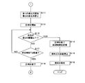
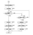
図2、図3及び図4は、排出弁の異常の判断手順を示すフローチャートである。制御部50は、第1の排出弁3及び第2の排出弁4の異常を判断するため定期的に以下の処理を行う。記憶部51は、気液分離器2の水位に係る第2の閾値を記憶している。第2の閾値に係る水位は第1の閾値に係る水位よりも低い。また、以下の処理の前に制御部50は第1の排出弁3及び第2の排出弁4を閉止する。
制御部50は、水位センサ20が検出した水位が第1の閾値以上であるか否かを判定する(S1)。制御部50は、水位センサ20が検出した水位が第1の閾値以上でないと判定した場合(S1:NO)、制御部50は、気液分離器2内の水及びガスが排出された時点からの積算発電量が所定値A以上か否かを判定する(S2)。このとき、制御部50は、計時部53が前記時点において記録した時刻からステップS2における判定の時刻までの経過時間とあらかじめ定められた時間ごとの発電量とにより、積算発電量を計算する。
制御部50は、気液分離器2内の水及びガスが排出された時点からの積算発電量が所定値A以上でないと判定した場合(S2:NO)、処理をステップS1へ戻す。制御部50は、気液分離器2内の水及びガスが排出された時点からの積算発電量が所定値A以上であると判定した場合(S2:YES)、水素供給部12に燃料ガスの供給の停止命令を出力し(S7)、燃料電池100の異常を出力し、報知部6に報知させる(S8)。制御部50が、積算発電量が所定値A以上であると判定した場合、気液分離器2内に所定量貯留されているはずの水が貯留されていないことになり、第1の排出弁3及び第2の排出弁4の両方に漏れが生じていることになる。
一方で、制御部50は、水位センサ20が検出した水位が第1の閾値以上であると判定した場合(S1:YES)、第1の排出弁3を閉止した状態で、第2の排出弁4を開放する(S3)。また、制御部50は、計時部53のタイマー機能による計時を開始する(S4)。
制御部50は、水位センサ20が検出する水位が第2の閾値以下であるか否かを判定する(S5)。制御部50は、水位センサ20が検出する水位が第2の閾値以下であると判定した場合(S5:YES)、計時部53に計時を終了させ、計時した経過時間を記憶部51に記憶させる(S6)。その後、制御部50は、水素供給部12に燃料ガスの供給を停止させ(S7)、第1の排出弁3の異常を出力し、報知部6に報知させる(S8)。このとき、第1の排出弁3から水が漏れていることになる。
一方、制御部50は、水位センサ20が検出する水位が第2の閾値以下でないと判定した場合(S5:NO)、所定時間T1が経過したか否かを判定する(S9)。所定時間T1は、気液分離器2の水位に係る第1の閾値及び第2の閾値の差分の水量をXとし、第1の排出弁3において許容される水の漏れ量をY1とした場合、T1>X/Y1として設定される。Y1は例えば、秒あたりの値として定められる。これにより、許容される水の漏れ量Y1以上に漏れが生じているという第1の排出弁3の異常を判断することができる。
制御部50は、所定時間T1が経過していないと判定した場合(S9:NO)、処理をステップS5に戻す。一方、所定時間T1が経過したと判定した場合(S9:YES)、計時部53に計時を終了させる(S10)。
その後、制御部50は、第1の排出弁3を開放し、第2の排出弁4を閉止する(S11)。また、制御部50は、計時部53のタイマー機能による計時を開始させる(S12)。
制御部50は、水位センサ20が検出する水位が第2の閾値以下であるか否かを判定する(S13)。制御部50は、水位センサ20が検出する水位が第2の閾値以下であると判定した場合(S13:YES)、計時部53に計時を終了させ、計時した経過時間を記憶部51に記憶させる(S14)。その後、制御部50は、水素供給部12に燃料ガスの供給を停止させ(S15)、第2の排出弁4の異常を出力し、報知部6に報知させる(S16)。このとき、第2の排出弁4から水が漏れていることになる。
一方、制御部50は、水位センサ20が検出する水位が第2の閾値以下でないと判定した場合(S13:NO)、所定時間T2が経過したか否かを判定する(S17)。所定時間T2は、第2の排出弁4において許容される水の漏れ量をY2とした場合、T2>X/Y2として設定されている。Y2は例えば、秒あたりの値として定められる。これにより、許容される水の漏れ量Y2以上に漏れが生じているという第2の排出弁4の異常を判断することができる。また、T2は、T2<T1として設定されている。これにより、水の排出過程全体における微量の漏れを考慮して、第2の排出弁4の異常を判断することができる。
制御部50は、所定時間T2が経過していないと判定した場合(S17:NO)、処理をステップS13へ戻す。一方、所定時間T2が経過したと判定した場合(S17:YES)、計時部53に計時を終了させる(S18)。
その後、制御部50は、第2の排出弁4を開放する(S19)。また、制御部50は、計時部53のタイマー機能による計時を開始させる(S20)。
制御部50は、水位センサ20が検出する水位が第2の閾値以下であるか否かを判定する(S21)。制御部50は、水位センサ20が検出する水位が第2の閾値以下であると判定した場合(S21:YES)、計時部53に計時を終了させる(S22)。その後、ガス及び水の排出を停止し、排出の終了時刻を記憶部51に記憶させる(S23)。その後、制御部50は、第1の排出弁3及び第2の排出弁4に異常がなく、異常の判断が正常に終了したことを報知部6に報知させる(S24)。
一方、制御部50は、水位センサ20が検出する水位が第2の閾値以下でないと判定した場合(S21:NO)、所定時間T3が経過したか否かを判定する(S25)。所定時間T3は、第1の排出弁3及び第2の排出弁4が時間ごとに最低でも排出すべき水の量をY3とした場合、T3=X/Y3として設定される。Y3は例えば、秒あたりの値として定められる。これにより、第1の排出弁3及び第2の排出弁4の排出する水の量が最低でも排出すべき水の量よりも少ないという異常を判断することができる。
制御部50は、所定時間T3が経過していないと判定した場合(S25:NO)、処理をステップS21に戻す。制御部50は、所定時間T3が経過したと判定した場合(S25:YES)、計時部53に計時を終了させる(S26)。その後、制御部50は、水素供給部12に燃料ガスの供給を停止させ(S27)、報知部6に第1の排出弁3及び第2の排出弁4の異常を報知させる(S28)。これにより、制御部50は、第1の排出弁3、又は第2の排出弁4あるいはその両方が開放されてない場合、気液分離器2内のガスの貯留が少なく、第1の排出弁3より上流の圧力が想定より小さい場合、気液分離器2からの排出経路に異物が詰まっている場合等の異常を判断することができる。
上記の構成によれば、気液分離器2内の水位の変化に基づいて第1の排出弁3及び第2の排出弁4の異常を判断するので、気液分離器2内のガスを排出する前に、第1の排出弁3及び第2の排出弁4の異常を判断することができる。したがって、気液分離器2内のガスを排出することなく第1の排出弁3及び第2の排出弁4の異常の判断が可能となる。
制御部50は、第1の排出弁3を閉止し、第2の排出弁4を開放した状態で、第2の閾値以下に水位が低下した場合に異常を出力し、報知部6に報知させる。また、水位が第2の閾値以下に低下した場合、第1の排出弁3から水が漏れていることになる。したがって、制御部50は、第1の排出弁3の閉止に係る異常を判断することができ、燃料電池100の使用者は異常を認知できる。
第1の排出弁3を開放し、第2の排出弁4を閉止した状態で、第2の閾値以下に水位が低下した場合に異常を出力し、報知部6に報知させる。また、水位が第2の閾値以下に低下した場合、第2の排出弁4から水が漏れていることになる。したがって、制御部50は、第2の排出弁4の閉止に係る異常を判断することができ、燃料電池100の使用者は異常を認知できる。
制御部50は、第1の排出弁3を閉止し、第2の排出弁4を開放した時点から水位が第2の閾値以下に低下する時点までに要する時間を計時部53に計時させ、記憶部51に記憶させるので、水位の低下量及び前記時間から排出弁の漏れの度合いを算出できる。また、第1の排出弁3を開放し、第2の排出弁4を閉止した場合も同様である。
制御部50は、ガス及び水を排出した時点から、第1の閾値まで水位が上昇していない場合に計時部53が前記時点において記録した時刻からの所定時間に係る積算発電量が所定値A以上か否かにより異常を判断し、異常を報知部6に報知させる。水位が第1の閾値まで上昇していない場合、発電により水が生成しているにもかかわらず、第1の排出弁3及び第2の排出弁4の両方に漏れが生じており、気液分離器2内に水が貯留されていないことになる。したがって、制御部50は、第1の排出弁3及び第2の排出弁4の両方の閉止に係る異常を判断することができ、燃料電池100の使用者は異常を認知できる。また、排出弁を開放させて気液分離器内のガスを排出することなく排出弁の異常を判断できる。
(実施の形態2)
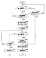
図5、図6及び図7は、実施の形態2に係る燃料電池100における排出弁の異常の判断手順を示すフローチャートである。実施の形態2に係る燃料電池100の構成について、実施の形態1と同様な構成については、同一の符号を付してその詳細な説明を省略する。
図5、図6及び図7は、実施の形態2に係る燃料電池100における排出弁の異常の判断手順を示すフローチャートである。実施の形態2に係る燃料電池100の構成について、実施の形態1と同様な構成については、同一の符号を付してその詳細な説明を省略する。
制御部50は、第1の排出弁3及び第2の排出弁4の異常を判断するため定期的に以下の処理を行う。記憶部51は、気液分離器2の水位に係る第1の閾値を記憶している。また、以下の処理の前に制御部50は第1の排出弁3及び第2の排出弁4を閉止する。
制御部50は、水位センサ20が検出した水位が第1の閾値以上であるか否かを判断する(S41)。制御部50は、水位センサ20が検出した水位が第1の閾値以上でないと判定した場合(S41:NO)、制御部50は、気液分離器2内の水及びガスが排出された時点からの積算発電量が所定値A以上か否かを判定する(S42)。ステップS42における積算発電量は実施の形態1と同様の方法により計算される。
制御部50は、気液分離器2内の水及びガスが排出された時点からの積算発電量が所定値A以上でないと判定した場合(S42:NO)、処理をステップS41へ戻す。制御部50は、気液分離器2内の水及びガスが排出された時点からの積算発電量が所定値A以上であると判定した場合(S42:YES)、水素供給部12に燃料ガスの供給の停止命令を出力し(S48)、燃料電池100の異常を出力し、報知部6に報知させる(S49)。制御部50が、積算発電量が所定値A以上であると判定した場合、気液分離器2内に所定量貯留されているはずの水が貯留されていないことになり、第1の排出弁3及び第2の排出弁4の両方に漏れが生じていることになる。
一方で、制御部50は、水位センサ20が検出した水位が第1の閾値以上であると判定した場合(S41:YES)、水位が第1の閾値以上となったと判定した時点からの積算発電量が所定値B以上であるか否かを判定する(S43)。このとき、制御部50は、水位が第1の閾値以上となったと判定した時刻からステップS43における判定の時刻までの経過時間とあらかじめ定められた時間ごとの発電量とにより、積算発電量を計算する。なお、所定値A>Bである。
制御部50は、水位が第1の閾値以上となったと判定した時点からの積算発電量が所定値B以上でないと判定した場合(S43:NO)、処理をステップS43に戻す。制御部50は、積算発電量が所定値B以上であると判定した場合(S43:YES)、第1の排出弁3を閉止した状態で、第2の排出弁4を開放する(S44)。また、制御部50は、計時部53のタイマー機能による計時を開始する(S45)。
制御部50は、水位センサ20が検出する水位が第1の閾値以下であるか否かを判定する(S46)。制御部50は、水位センサ20が検出する水位が第1の閾値以下であると判定した場合(S46:YES)、計時部53に計時を終了させ、計時した経過時間を記憶部51に記憶させる(S47)。その後、制御部50は、水素供給部12に燃料ガスの供給を停止させ(S48)、第1の排出弁3の異常を出力し、報知部6に報知させる(S49)。このとき、第1の排出弁3から水が漏れていることになる。
一方、制御部50は、水位センサ20が検出する水位が第1の閾値以下でないと判定した場合(S46:NO)、所定時間T1が経過したか否かを判定する(S50)。所定時間T1は、実施の形態1と同様に定められる。
制御部50は、所定時間T1が経過していないと判定した場合(S50:NO)、処理をステップS46に戻す。一方、所定時間T1が経過したと判定した場合(S50:YES)、計時部53に計時を終了させる(S51)。
その後、制御部50は、第1の排出弁3を開放し、第2の排出弁4を閉止する(S52)。また、制御部50は、計時部53のタイマー機能による計時を開始させる(S53)。
制御部50は、水位センサ20が検出する水位が第1の閾値以下であるか否かを判定する(S54)。制御部50は、水位センサ20が検出する水位が第1の閾値以下であると判定した場合(S54:YES)、計時部53に計時を終了させ、計時した経過時間を記憶部51に記憶させる(S55)。その後、制御部50は、水素供給部12に燃料ガスの供給を停止させ(S56)、第2の排出弁4の異常を出力し、報知部6に報知させる(S57)。このとき、第2の排出弁4から水が漏れていることになる。
一方、制御部50は、水位センサ20が検出する水位が第1の閾値以下でないと判定した場合(S54:NO)、所定時間T2が経過したか否かを判定する(S58)。所定時間T2は、実施の形態1と同様に定められる。
制御部50は、所定時間T2が経過していないと判定した場合(S58:NO)、処理をステップS54へ戻す。一方、所定時間T2が経過したと判定した場合(S58:YES)、計時部53に計時を終了させる(S59)。
その後、制御部50は、第2の排出弁4を開放する(S60)。また、制御部50は、計時部53のタイマー機能による計時を開始させる(S61)。
制御部50は、水位センサ20が検出する水位が第1の閾値以下であるか否かを判定する(S62)。制御部50は、水位センサ20が検出する水位が第1の閾値以下であると判定した場合(S62:YES)、計時部53に計時を終了させる(S63)。その後、ガス及び水の排出を停止し、排出の終了時刻を記憶部51に記憶させる(S64)。その後、制御部50は、第1の排出弁3及び第2の排出弁4に異常がなく、異常の判断が正常に終了したことを報知部6に報知させる(S65)。
一方、制御部50は、水位センサ20が検出する水位が第1の閾値以下でないと判定した場合(S62:NO)、所定時間T3が経過したか否かを判定する(S66)。所定時間T3は、実施の形態1と同様に定められる。
制御部50は、所定時間T3が経過していないと判定した場合(S66:NO)、処理をステップS62に戻す。制御部50は、所定時間T3が経過したと判定した場合(S66:YES)、計時部53に計時を終了させる(S67)。その後、制御部50は、水素供給部12に燃料ガスの供給を停止させ(S68)、報知部6に第1の排出弁3及び第2の排出弁4の異常を報知させる(S69)。これにより、制御部50は、第1の排出弁3、又は第2の排出弁4あるいはその両方が開放されてない場合、気液分離器2内のガスの貯留が少なく、第1の排出弁3より上流の圧力が想定より小さい場合、気液分離器2からの排出経路に異物が詰まっている場合等の異常を判断することができる。
上記の構成によれば、実施の形態1と同様に気液分離器2内のガスを排出する前に、第1の排出弁3及び第2の排出弁4の異常を判断することができる。したがって、気液分離器2内のガスを排出することなく第1の排出弁3及び第2の排出弁4の異常の判断が可能となる。
制御部50は、実施の形態1と同様に第1の排出弁3を閉止し、第2の排出弁4を開放した状態で、第1の閾値以下に水位が低下した場合に異常を出力し、報知部6に報知させる。また、水位が第1の閾値以下に低下した場合、第1の排出弁3から水が漏れていることになる。したがって、制御部50は、第1の排出弁3の閉止に係る異常を判断することができ、燃料電池100の使用者は異常を認知できる。
更に、制御部50は、第1の排出弁3を開放し、第2の排出弁4を閉止した状態で、第1の閾値以下に水位が低下した場合に異常を出力し、報知部6に報知させる。また、水位が第1の閾値以下に低下した場合、第2の排出弁4から水が漏れていることになる。したがって、制御部50は、第2の排出弁4の閉止に係る異常を判断することができ、燃料電池100の使用者は異常を認知できる。
制御部50は、第1の排出弁3を閉止し、第2の排出弁4を開放した時点から水位が第1の閾値以下に低下する時点までに要する時間を計時部53に計時させ、記憶部51に記憶させるので、水位の低下量及び前記時間から排出弁の漏れの度合いを算出できる。また、第1の排出弁3を開放し、第2の排出弁4を閉止した場合も同様である。
制御部50は、ガス及び水を排出した時点から、第1の閾値まで水位が上昇していない場合に計時部53が前記時点において記録した時刻からの所定時間に係る積算発電量が所定値A以上か否かにより異常を判断し、異常を報知部6に報知させる。水位が第1の閾値まで上昇していない場合、発電により水が生成しているにもかかわらず、第1の排出弁3及び第2の排出弁4の両方に漏れが生じており、気液分離器2内に水が貯留されていないことになる。したがって、制御部50は、第1の排出弁3及び第2の排出弁4の両方の閉止に係る異常を判断することができ、燃料電池100の使用者は異常を認知できる。また、排出弁を開放させて気液分離器内のガスを排出することなく排出弁の異常を判断できる。
実施の形態1と異なり、制御部50は、水位が第1の閾値以上となったと判定した場合に、積算発電量が所定値B以上であるか否かを判定し、その後第1の排出弁3及び第2の排出弁4の異常を判断する。これにより、水位に係る第2の閾値を用いずに、第1の閾値のみを用いて、実施の形態1と同様に第1の排出弁3及び第2の排出弁4の異常を判断できる。また、第1の閾値のみで第1の排出弁3及び第2の排出弁4の異常を判断することにより、異常の判断の構成を簡略化できる。
なお、上述した燃料電池100は、第1の排出弁3の異常の判断の後、第2の排出弁4の異常を判断する構成としたが、第2の排出弁4の異常を先に判断した後、第1の排出弁3の異常を判断する構成としてもよい。また、燃料電池100は、第1の排出弁3又は第2の排出弁4のいずれか一方のみを有する構成であってもよい。
更に、燃料電池100は、第1の排出弁3及び第2の排出弁4の二つの排出弁を有する構成としたが、気液分離器2に三つ以上の排出弁を直列に接続する構成であってもよい。排出弁が三つ以上である場合においても、一の排出弁を閉止し、他の開放弁を開放する動作を、排出弁ごとに繰り返すことにより異常の判断を行うことができる。
以上のように、本発明に係る燃料電池は、ガス及び水を分離し、貯留する気液分離器と、前記ガス及び水を排出する排出弁と、該排出弁の動作を制御する制御部とを備える燃料電池において、前記気液分離器の水位を検出する検出部を備え、前記制御部は、前記検出部が検出した水位が閾値以上である場合、前記排出弁の開閉に伴う前記水位の変化に基づいて、前記排出弁の異常を判断するように構成されていることを特徴とする。
本発明によれば、制御部は、気液分離器内の水位の変化に基づいて排出弁の異常を判断するので、ガスを排出する前に、排出弁の異常を判断することができる。したがって、制御部は、気液分離器内のガスを排出することなく排出弁の異常の判断ができる。
本発明に係る燃料電池は、複数の前記排出弁が直列に配されており、前記制御部は、一の前記排出弁を閉止し、他の前記排出弁を開放し、前記検出部が検出した水位が前記閾値以下の第2の閾値以下である場合、前記一の排出弁の異常を示す信号を出力するように構成されていることを特徴とする。
本発明によれば、制御部は、一の排出弁を閉止し、他の開放弁を開放し、第2の閾値以下に水位が低下した場合に異常を出力する。水位が第2の閾値以下に低下した場合、一の排出弁から水が漏れていることになる。したがって、制御部は一の排出弁の閉止に係る異常を判断することができる。
本発明に係る燃料電池は、前記制御部は、前記一の排出弁を開放し、前記他の排出弁を閉止し、前記検出部が検出した水位が前記第2の閾値以下である場合、前記他の排出弁の異常を示す信号を出力するように構成されていることを特徴とする。
本発明によれば、制御部は、一の排出弁を開放し、他の開放弁を閉止した状態で、第2の閾値以下に水位が低下した場合に異常を出力する。水位が第2の閾値以下に低下した場合、他の排出弁から水が漏れていることになる。したがって、制御部は他の排出弁の閉止に係る異常を判断することができる。
本発明に係る燃料電池は、前記制御部が一の排出弁の閉止及び他の排出弁の開放を実行した時点から、前記検出部が前記第2の閾値以下の水位を検出する時点までの経過時間を計時する計時部と、前記経過時間を記憶する記憶部とを備えることを特徴とする。
本発明によれば、計時部が一の排出弁を閉止し、他の開放弁を開放した時点から水位が第2の閾値以下に低下する時点までに要する時間を計時し、記憶部が前記時間を記憶するので、水位の低下量及び前記時間から排出弁の漏れの度合いを算出できる。
本発明に係る燃料電池は、ガス及び水を分離し、貯留する気液分離器と、前記ガス及び水を排出する複数の排出弁と、該排出弁の動作を制御する制御部とを備える燃料電池において、前記気液分離器の水位を検出する検出部と、前記ガス及び水を排出した時点からの経過時間を計時する計時部とを備え、前記制御部は、該計時部が所定時間を計時した後、前記検出部が閾値以下の水位を検出した場合に前記排出弁の異常を判断するように構成されていることを特徴とする。
本発明によれば、前記ガス及び水を排出した時点から、所定時間内に水位が閾値まで上昇していない場合に異常を判断する。水位が閾値まで上昇していない場合、発電により水が生成しているにもかかわらず、気液分離器内にて所定量貯留されているはずの水が貯留されておらず、複数の排出弁に漏れが生じていることになる。したがって、制御部は複数の排出弁の閉止に係る異常を判断し、排出弁を開放させて気液分離器内のガスを排出することなく排出弁の異常を判断できる。
本発明に係る異常判断方法は、ガス及び水を分離し、貯留する気液分離器と、該気液分離器の水位を検出する検出部と、前記ガス及び水を排出し、直列に配された複数の排出弁と、該複数の排出弁の動作を制御する制御部とを備える燃料電池の前記排出弁の異常を判断する異常判断方法であって、前記検出部が検出した水位が閾値以上であるか否かを判定し、前記検出部が検出した水位が前記閾値以上であると判定した場合、前記制御部による前記排出弁の開閉に伴う前記水位の変化に基づいて、前記排出弁の異常を判断することを特徴とする。
本発明によれば、気液分離器内の水位の変化に基づいて排出弁の異常を判断するので、ガスを排出する前に、排出弁の異常を判断することができる。したがって、気液分離器内のガスを排出することなく排出弁の異常の判断ができる。
本発明に係るプログラムは、ガス及び水を分離し、貯留する気液分離器と、該気液分離器の水位を検出する検出部と、前記ガス及び水を排出する複数の排出弁と、該複数の排出弁の動作を制御する制御部とを備える燃料電池の前記排出弁の異常を判断するコンピュータに、前記検出部が検出した水位が閾値以上であるか否かを判定し、前記検出部が検出した水位が前記閾値以上であると判定した場合、前記制御部による前記排出弁の開閉に伴う前記水位の変化に基づいて、前記排出弁の異常を判断する処理を実行させることを特徴とする。
本発明によれば、気液分離器内の水位の変化に基づいて排出弁の異常を判断するので、ガスを排出する前に、排出弁の異常を判断することができる。したがって、気液分離器内のガスを排出することなく排出弁の異常の判断ができる。
今回開示された実施の形態はすべての点で例示であって、制限的なものではないと考えられるべきである。本発明の範囲は、上記した意味ではなく、請求の範囲によって示され、請求の範囲と均等の意味及び範囲内でのすべての変更が含まれることが意図される。即ち、請求項に示した範囲で適宜変更した技術的手段を組み合わせて得られる実施形態も本発明の技術的範囲に含まれる。
2 気液分離器
20 水位センサ
3 第1の排出弁
4 第2の排出弁
50 制御部
54 プログラム
20 水位センサ
3 第1の排出弁
4 第2の排出弁
50 制御部
54 プログラム
Claims (7)
- ガス及び水を分離し、貯留する気液分離器と、前記ガス及び水を排出する排出弁と、該排出弁の動作を制御する制御部とを備える燃料電池において、
前記気液分離器の水位を検出する検出部を備え、
前記制御部は、前記検出部が検出した水位が閾値以上である場合、前記排出弁の開閉に伴う前記水位の変化に基づいて、前記排出弁の異常を判断するように構成されていること
を特徴とする燃料電池。 - 複数の前記排出弁が直列に配されており、
前記制御部は、
一の前記排出弁を閉止し、他の前記排出弁を開放し、
前記検出部が検出した水位が前記閾値以下の第2の閾値以下である場合、前記一の排出弁の異常を示す信号を出力する
ように構成されていること
を特徴とする請求項1に記載の燃料電池。 - 前記制御部は、
前記一の排出弁を開放し、前記他の排出弁を閉止し、
前記検出部が検出した水位が前記第2の閾値以下である場合、前記他の排出弁の異常を示す信号を出力する
ように構成されていることを特徴とする請求項2に記載の燃料電池。 - 前記制御部が一の排出弁の閉止及び他の排出弁の開放を実行した時点から、前記検出部が前記第2の閾値以下の水位を検出する時点までの経過時間を計時する計時部と、
前記経過時間を記憶する記憶部とを備える
ことを特徴とする請求項2又は3に記載の燃料電池。 - ガス及び水を分離し、貯留する気液分離器と、前記ガス及び水を排出する複数の排出弁と、該排出弁の動作を制御する制御部とを備える燃料電池において、
前記気液分離器の水位を検出する検出部と、
前記ガス及び水を排出した時点からの経過時間を計時する計時部と
を備え、
前記制御部は、該計時部が所定時間を計時した後、前記検出部が閾値以下の水位を検出した場合に前記排出弁の異常を判断するように構成されていること
を特徴とする燃料電池。 - ガス及び水を分離し、貯留する気液分離器と、該気液分離器の水位を検出する検出部と、前記ガス及び水を排出し、直列に配された複数の排出弁と、該複数の排出弁の動作を制御する制御部とを備える燃料電池の前記排出弁の異常を判断する異常判断方法であって、
前記検出部が検出した水位が閾値以上であるか否かを判定し、
前記検出部が検出した水位が前記閾値以上であると判定した場合、前記制御部による前記排出弁の開閉に伴う前記水位の変化に基づいて、前記排出弁の異常を判断する
ことを特徴とする異常判断方法。 - ガス及び水を分離し、貯留する気液分離器と、該気液分離器の水位を検出する検出部と、前記ガス及び水を排出する複数の排出弁と、該複数の排出弁の動作を制御する制御部とを備える燃料電池の前記排出弁の異常を判断するコンピュータに、
前記検出部が検出した水位が閾値以上であるか否かを判定し、
前記検出部が検出した水位が前記閾値以上であると判定した場合、前記制御部による前記排出弁の開閉に伴う前記水位の変化に基づいて、前記排出弁の異常を判断する
処理を実行させることを特徴とするプログラム。
Applications Claiming Priority (2)
| Application Number | Priority Date | Filing Date | Title |
|---|---|---|---|
| JP2015053885 | 2015-03-17 | ||
| JP2015-053885 | 2015-03-17 |
Publications (1)
| Publication Number | Publication Date |
|---|---|
| WO2016147462A1 true WO2016147462A1 (ja) | 2016-09-22 |
Family
ID=56918868
Family Applications (1)
| Application Number | Title | Priority Date | Filing Date |
|---|---|---|---|
| PCT/JP2015/079500 Ceased WO2016147462A1 (ja) | 2015-03-17 | 2015-10-20 | 燃料電池、異常判断方法及びプログラム |
Country Status (2)
| Country | Link |
|---|---|
| US (1) | US10553888B2 (ja) |
| WO (1) | WO2016147462A1 (ja) |
Families Citing this family (2)
| Publication number | Priority date | Publication date | Assignee | Title |
|---|---|---|---|---|
| KR102540876B1 (ko) * | 2017-12-19 | 2023-06-07 | 현대자동차주식회사 | 연료 전지 고장 진단 장치 및 방법 |
| JP7120978B2 (ja) * | 2019-09-19 | 2022-08-17 | 本田技研工業株式会社 | 故障検知処理方法 |
Citations (4)
| Publication number | Priority date | Publication date | Assignee | Title |
|---|---|---|---|---|
| JP2005050554A (ja) * | 2003-07-29 | 2005-02-24 | Toyota Motor Corp | 燃料電池システム |
| JP2005302708A (ja) * | 2004-03-16 | 2005-10-27 | Toyota Motor Corp | 燃料電池システム |
| JP2008041346A (ja) * | 2006-08-03 | 2008-02-21 | Toyota Motor Corp | 燃料電池システム及び排気弁の異常判定方法 |
| JP2009152092A (ja) * | 2007-12-21 | 2009-07-09 | Panasonic Corp | 燃料電池システム |
Family Cites Families (1)
| Publication number | Priority date | Publication date | Assignee | Title |
|---|---|---|---|---|
| DE602005017876D1 (de) | 2004-03-16 | 2010-01-07 | Toyota Motor Co Ltd | Brennstoffzellensystem und steuerverfahren dafür |
-
2015
- 2015-10-20 WO PCT/JP2015/079500 patent/WO2016147462A1/ja not_active Ceased
-
2016
- 2016-02-17 US US15/045,987 patent/US10553888B2/en active Active
Patent Citations (4)
| Publication number | Priority date | Publication date | Assignee | Title |
|---|---|---|---|---|
| JP2005050554A (ja) * | 2003-07-29 | 2005-02-24 | Toyota Motor Corp | 燃料電池システム |
| JP2005302708A (ja) * | 2004-03-16 | 2005-10-27 | Toyota Motor Corp | 燃料電池システム |
| JP2008041346A (ja) * | 2006-08-03 | 2008-02-21 | Toyota Motor Corp | 燃料電池システム及び排気弁の異常判定方法 |
| JP2009152092A (ja) * | 2007-12-21 | 2009-07-09 | Panasonic Corp | 燃料電池システム |
Also Published As
| Publication number | Publication date |
|---|---|
| US10553888B2 (en) | 2020-02-04 |
| US20160276684A1 (en) | 2016-09-22 |
Similar Documents
| Publication | Publication Date | Title |
|---|---|---|
| US11383691B2 (en) | Fuel cell system, control method of fuel cell system, and computer program | |
| JP4806989B2 (ja) | 燃料電池システム | |
| CN104143647B (zh) | 用于估算燃料电池状态的系统和方法 | |
| US7476458B2 (en) | Fuel cell system | |
| RU2402841C1 (ru) | Система топливных элементов | |
| US7581431B2 (en) | Gas leak detection device and method for same | |
| KR101637720B1 (ko) | 연료전지 시스템의 제어 방법 | |
| US20190217845A1 (en) | Fuel cell system, control method of fuel cell system, and computer program | |
| KR102614135B1 (ko) | 연료전지의 공기 공급 제어방법 및 제어시스템 | |
| KR102842936B1 (ko) | 연료전지시스템의 연료극 배출밸브 제어 장치 및 그 방법 | |
| KR20080098529A (ko) | 연료전지시스템 | |
| JP2013171737A (ja) | 燃料電池システムの漏れ異常判定方法 | |
| US11069911B2 (en) | Fuel cell system and control method of fuel cell system | |
| JP2017145903A (ja) | ガス供給システムの運転方法 | |
| JP2020021533A (ja) | 燃料電池システム | |
| JP4172792B2 (ja) | 直接型メタノール燃料電池の燃料濃度検出方法および直接型メタノール燃料電池システム | |
| JP3879429B2 (ja) | 燃料電池システム | |
| JP4414808B2 (ja) | 燃料電池システム | |
| US10553888B2 (en) | Fuel cell and abnormality determination method | |
| JP4765349B2 (ja) | 燃料電池の異常検知装置 | |
| JP2008256552A (ja) | ガス漏れ検出方法及びガス流通システム | |
| JP5304863B2 (ja) | 燃料電池システム | |
| JP4582390B2 (ja) | 燃料電池劣化診断装置 | |
| JP2007165103A (ja) | 燃料電池システム及びその運転方法並びに移動体 | |
| JP4982977B2 (ja) | 燃料電池システム |
Legal Events
| Date | Code | Title | Description |
|---|---|---|---|
| 121 | Ep: the epo has been informed by wipo that ep was designated in this application |
Ref document number: 15885554 Country of ref document: EP Kind code of ref document: A1 |
|
| NENP | Non-entry into the national phase |
Ref country code: DE |
|
| 122 | Ep: pct application non-entry in european phase |
Ref document number: 15885554 Country of ref document: EP Kind code of ref document: A1 |
|
| NENP | Non-entry into the national phase |
Ref country code: JP |