WO2016143824A1 - Composition kit, layered body and method for manufacturing same, and bandpass filter - Google Patents
Composition kit, layered body and method for manufacturing same, and bandpass filter Download PDFInfo
- Publication number
- WO2016143824A1 WO2016143824A1 PCT/JP2016/057391 JP2016057391W WO2016143824A1 WO 2016143824 A1 WO2016143824 A1 WO 2016143824A1 JP 2016057391 W JP2016057391 W JP 2016057391W WO 2016143824 A1 WO2016143824 A1 WO 2016143824A1
- Authority
- WO
- WIPO (PCT)
- Prior art keywords
- group
- wavelength
- general formula
- composition
- absorbance
- Prior art date
Links
Images


Classifications
-
- C—CHEMISTRY; METALLURGY
- C09—DYES; PAINTS; POLISHES; NATURAL RESINS; ADHESIVES; COMPOSITIONS NOT OTHERWISE PROVIDED FOR; APPLICATIONS OF MATERIALS NOT OTHERWISE PROVIDED FOR
- C09K—MATERIALS FOR MISCELLANEOUS APPLICATIONS, NOT PROVIDED FOR ELSEWHERE
- C09K19/00—Liquid crystal materials
- C09K19/52—Liquid crystal materials characterised by components which are not liquid crystals, e.g. additives with special physical aspect: solvents, solid particles
- C09K19/54—Additives having no specific mesophase characterised by their chemical composition
-
- C—CHEMISTRY; METALLURGY
- C08—ORGANIC MACROMOLECULAR COMPOUNDS; THEIR PREPARATION OR CHEMICAL WORKING-UP; COMPOSITIONS BASED THEREON
- C08F—MACROMOLECULAR COMPOUNDS OBTAINED BY REACTIONS ONLY INVOLVING CARBON-TO-CARBON UNSATURATED BONDS
- C08F2/00—Processes of polymerisation
- C08F2/44—Polymerisation in the presence of compounding ingredients, e.g. plasticisers, dyestuffs, fillers
-
- C—CHEMISTRY; METALLURGY
- C08—ORGANIC MACROMOLECULAR COMPOUNDS; THEIR PREPARATION OR CHEMICAL WORKING-UP; COMPOSITIONS BASED THEREON
- C08K—Use of inorganic or non-macromolecular organic substances as compounding ingredients
- C08K5/00—Use of organic ingredients
- C08K5/0008—Organic ingredients according to more than one of the "one dot" groups of C08K5/01 - C08K5/59
- C08K5/0041—Optical brightening agents, organic pigments
-
- C—CHEMISTRY; METALLURGY
- C09—DYES; PAINTS; POLISHES; NATURAL RESINS; ADHESIVES; COMPOSITIONS NOT OTHERWISE PROVIDED FOR; APPLICATIONS OF MATERIALS NOT OTHERWISE PROVIDED FOR
- C09K—MATERIALS FOR MISCELLANEOUS APPLICATIONS, NOT PROVIDED FOR ELSEWHERE
- C09K19/00—Liquid crystal materials
- C09K19/04—Liquid crystal materials characterised by the chemical structure of the liquid crystal components, e.g. by a specific unit
- C09K19/06—Non-steroidal liquid crystal compounds
- C09K19/08—Non-steroidal liquid crystal compounds containing at least two non-condensed rings
- C09K19/10—Non-steroidal liquid crystal compounds containing at least two non-condensed rings containing at least two benzene rings
- C09K19/14—Non-steroidal liquid crystal compounds containing at least two non-condensed rings containing at least two benzene rings linked by a carbon chain
- C09K19/18—Non-steroidal liquid crystal compounds containing at least two non-condensed rings containing at least two benzene rings linked by a carbon chain the chain containing carbon-to-carbon triple bonds, e.g. tolans
-
- C—CHEMISTRY; METALLURGY
- C09—DYES; PAINTS; POLISHES; NATURAL RESINS; ADHESIVES; COMPOSITIONS NOT OTHERWISE PROVIDED FOR; APPLICATIONS OF MATERIALS NOT OTHERWISE PROVIDED FOR
- C09K—MATERIALS FOR MISCELLANEOUS APPLICATIONS, NOT PROVIDED FOR ELSEWHERE
- C09K19/00—Liquid crystal materials
- C09K19/52—Liquid crystal materials characterised by components which are not liquid crystals, e.g. additives with special physical aspect: solvents, solid particles
- C09K19/54—Additives having no specific mesophase characterised by their chemical composition
- C09K19/56—Aligning agents
-
- C—CHEMISTRY; METALLURGY
- C09—DYES; PAINTS; POLISHES; NATURAL RESINS; ADHESIVES; COMPOSITIONS NOT OTHERWISE PROVIDED FOR; APPLICATIONS OF MATERIALS NOT OTHERWISE PROVIDED FOR
- C09K—MATERIALS FOR MISCELLANEOUS APPLICATIONS, NOT PROVIDED FOR ELSEWHERE
- C09K19/00—Liquid crystal materials
- C09K19/52—Liquid crystal materials characterised by components which are not liquid crystals, e.g. additives with special physical aspect: solvents, solid particles
- C09K19/58—Dopants or charge transfer agents
- C09K19/586—Optically active dopants; chiral dopants
-
- G—PHYSICS
- G02—OPTICS
- G02B—OPTICAL ELEMENTS, SYSTEMS OR APPARATUS
- G02B5/00—Optical elements other than lenses
- G02B5/20—Filters
- G02B5/22—Absorbing filters
-
- G—PHYSICS
- G02—OPTICS
- G02B—OPTICAL ELEMENTS, SYSTEMS OR APPARATUS
- G02B5/00—Optical elements other than lenses
- G02B5/20—Filters
- G02B5/26—Reflecting filters
-
- C—CHEMISTRY; METALLURGY
- C09—DYES; PAINTS; POLISHES; NATURAL RESINS; ADHESIVES; COMPOSITIONS NOT OTHERWISE PROVIDED FOR; APPLICATIONS OF MATERIALS NOT OTHERWISE PROVIDED FOR
- C09K—MATERIALS FOR MISCELLANEOUS APPLICATIONS, NOT PROVIDED FOR ELSEWHERE
- C09K19/00—Liquid crystal materials
- C09K19/04—Liquid crystal materials characterised by the chemical structure of the liquid crystal components, e.g. by a specific unit
- C09K2019/0444—Liquid crystal materials characterised by the chemical structure of the liquid crystal components, e.g. by a specific unit characterized by a linking chain between rings or ring systems, a bridging chain between extensive mesogenic moieties or an end chain group
- C09K2019/0448—Liquid crystal materials characterised by the chemical structure of the liquid crystal components, e.g. by a specific unit characterized by a linking chain between rings or ring systems, a bridging chain between extensive mesogenic moieties or an end chain group the end chain group being a polymerizable end group, e.g. -Sp-P or acrylate
-
- C—CHEMISTRY; METALLURGY
- C09—DYES; PAINTS; POLISHES; NATURAL RESINS; ADHESIVES; COMPOSITIONS NOT OTHERWISE PROVIDED FOR; APPLICATIONS OF MATERIALS NOT OTHERWISE PROVIDED FOR
- C09K—MATERIALS FOR MISCELLANEOUS APPLICATIONS, NOT PROVIDED FOR ELSEWHERE
- C09K19/00—Liquid crystal materials
- C09K19/04—Liquid crystal materials characterised by the chemical structure of the liquid crystal components, e.g. by a specific unit
- C09K19/06—Non-steroidal liquid crystal compounds
- C09K19/08—Non-steroidal liquid crystal compounds containing at least two non-condensed rings
- C09K19/10—Non-steroidal liquid crystal compounds containing at least two non-condensed rings containing at least two benzene rings
- C09K19/14—Non-steroidal liquid crystal compounds containing at least two non-condensed rings containing at least two benzene rings linked by a carbon chain
- C09K19/18—Non-steroidal liquid crystal compounds containing at least two non-condensed rings containing at least two benzene rings linked by a carbon chain the chain containing carbon-to-carbon triple bonds, e.g. tolans
- C09K2019/188—Ph-C≡C-Ph-C≡C-Ph
Definitions
- the present invention relates to a composition kit, a laminate, a method for producing the same, and a bandpass filter.
- bandpass filters that selectively transmit and / or shield light of a specific wavelength have been used as optical members.
- a band pass filter there is a laminated body (multilayer film) in which high refractive index layers and low refractive index layers are alternately laminated (see Patent Documents 1 to 3).
- the high refractive index layer and the low refractive index layer included in the laminate described in the above-mentioned patent document are formed by vapor deposition, it takes time and labor to produce the laminate, and the cost is high. Also, in principle, there is a problem of angle dependency that the selective reflection wavelength (shielding wavelength) shifts depending on the angle at which this laminate is observed.
- An object of this invention is to provide the composition kit used suitably in order to manufacture the band pass filter with which angle dependence was reduced more simply in view of the said situation.
- Another object of the present invention is to provide a laminate suitably used for forming a bandpass filter with reduced angle dependency.
- another object of the present invention is to provide a method for manufacturing a laminate and a bandpass filter.
- a first composition comprising a liquid crystal compound having a polymerizable group and a right-turning chiral agent; A second composition comprising a liquid crystal compound having a polymerizable group and a left-turning chiral agent; And a third composition containing a coloring material.
- the left-turning chiral agent is selected from the group consisting of a compound represented by the following general formula (1) and a compound represented by the following general formula (2): The composition kit according to any one of (3).
- the left-turning chiral agent is selected from the group consisting of a compound represented by the following general formula (3) and a compound represented by the following general formula (4): The composition kit according to any one of (4).
- the liquid crystal compound having a polymerizable group has a refractive index anisotropy ⁇ n at 30 ° C. of 0.25 or more.
- the composition kit according to any one of (1) to (7), wherein the liquid crystal compound having a polymerizable group is a compound represented by the following general formula (5).
- each of the first composition and the second composition further contains a photopolymerization initiator.
- composition kit according to (13) which is used for forming a bandpass filter having a ratio of absorbance at a wavelength of 750 nm to absorbance at a wavelength of 850 nm of 3 or more.
- composition kit according to (15) which is used for forming a bandpass filter having a ratio of absorbance at a wavelength of 840 nm to absorbance at a wavelength of 940 nm of 3 or more.
- the reflective laminated film includes at least one light reflecting layer Xa formed by fixing a right-turning cholesteric liquid crystal phase and at least one light reflecting layer Xb formed by fixing a left-turning cholesteric liquid crystal phase.
- the selective reflection wavelength of at least one layer of the light reflection layer Xa is equal to the selective reflection wavelength of at least one layer of the light reflection layer Xb,
- the light absorption layer is a laminate including a color material.
- the light-reflective layer Xa includes a right-turning chiral agent having a helical twisting force of 30 ⁇ m ⁇ 1 or more, The laminate according to (18), wherein the light reflecting layer Xb includes a left-turning chiral agent having a helical twisting force of 30 ⁇ m ⁇ 1 or more.
- the left-turning chiral agent is selected from the group consisting of a compound represented by the following general formula (1) and a compound represented by the following general formula (2) (18) or The laminate according to (19).
- the left-turning chiral agent is selected from the group consisting of a compound represented by the following general formula (3) and a compound represented by the following general formula (4): (20) The laminated body in any one of. (22) The laminate according to any one of (18) to (21), wherein the color material contains a pigment. (23) having at least one of the light reflecting layer Xa and the light reflecting layer Xb in two or more layers, When there are a plurality of light reflecting layers Xa, the kind of chiral agent contained in each light reflecting layer Xa is the same, The laminate according to any one of (18) to (22), wherein when there are a plurality of light reflecting layers Xb, the kind of chiral agent contained in each light reflecting layer Xb is the same.
- the composition kit used suitably in order to manufacture the band pass filter with which angle dependence was reduced more simply can be provided.
- the laminated body used suitably for formation of the band pass filter with which angle dependence was reduced can also be provided.
- the manufacturing method of a laminated body and a band pass filter can also be provided.
- 4 is a graph showing a transmission spectrum of a substrate having an infrared transmission film C.
- 4 is a graph showing a transmission spectrum of a bandpass filter A.
- 3 is a graph showing a transmission spectrum of a bandpass filter B.
- 3 is a graph showing a transmission spectrum of a bandpass filter C. It is a graph which shows the transmission spectrum of laminated body (G1-1), (G4), (G5), (G6), (G7), (G8), (G9), and (G10). It is a graph which shows the transmission spectrum of a combination (G13).
- 3 is a graph showing a transmission spectrum of a bandpass filter D.
- 4 is a graph showing a transmission spectrum of a bandpass filter E.
- 4 is a graph showing a transmission spectrum of a bandpass filter F.
- composition kit of the present invention a laminate (cholesteric liquid crystal laminate), a production method thereof, and preferred embodiments of the bandpass filter will be described in detail.
- the description of the constituent elements described below may be made based on typical embodiments of the present invention, but the present invention is not limited to such embodiments.
- a numerical range represented by using “to” means a range including numerical values described before and after “to” as a lower limit value and an upper limit value.
- substitution and non-substitution includes those having no substituent and those having a substituent.
- the “alkyl group” includes not only an alkyl group having no substituent (unsubstituted alkyl group) but also an alkyl group having a substituent (substituted alkyl group).
- infrared light (infrared light)” in this specification means light having a wavelength of about 700 nm to about 1 mm.
- visible light (visible light)” means light having a wavelength of about 400 nm or more and less than 700 nm.
- FIG. 1 is a cross-sectional view of the laminate 10, and the laminate 10 includes a substrate 12, a reflective laminate film 14, and a light absorption layer 16 in this order.
- the reflective laminated film 14 is a film composed of a plurality of light reflecting layers arranged adjacent to each other, and includes a light reflecting layer Xa (18a) in which a right-turning cholesteric liquid crystal phase is fixed, and a left-turning property.
- the laminate 10 corresponds to a so-called selective wavelength transmission filter (bandpass filter).
- bandpass filter selective wavelength transmission filter
- light having a predetermined wavelength is selectively reflected by the reflective laminated film 14 and only light having a predetermined wavelength is transmitted.
- a part of the light transmitted through the reflective laminated film 14 is absorbed by the light absorption layer 16, and only light having a predetermined wavelength is transmitted. That is, in the laminated body 10, light having a predetermined wavelength is reflected by the reflective laminated film 14, and light having a predetermined wavelength is absorbed by the light absorption layer 16.
- the laminated body 10 functions as a wavelength-selective filter.
- the band of light that passes through the laminate 10 corresponds to the wavelength region in which the transmission spectrum of the reflective laminated film 14 and the transmission spectrum of the light absorption layer 16 are overlapped and transmitted in both transmission spectra.
- transmission band corresponds to the wavelength region in which the transmission spectrum of the reflective laminated film 14 and the transmission spectrum of the light absorption layer 16 are overlapped and transmitted in both transmission spectra.
- the range of the infrared ray reflected by the reflective laminated film 14 is not particularly limited, but it is preferable that the reflective laminated film 14 reflects at least a part of light having a wavelength of 650 to 1200 nm. More specifically, light having a specific wavelength out of the wavelength range of 650 to 1200 nm (eg, 730 nm ⁇ 100 nm, 850 nm ⁇ 100 nm, or 940 nm ⁇ 100 nm) is transmitted, and light in other regions is reflected. It is preferable to make it.
- the above transmission means that the maximum transmittance in the above range is 50% or more. Reflection means that the maximum transmittance in the above range is 30% or less.
- the laminated body 10 since the light reflecting layer Xa (18a) and the light reflecting layer Xb (18b) are laminated adjacent to each other without using an adhesive material, the planar shape of the laminated body 10 is good. As will be described later, the laminate 10 can be easily produced by using a predetermined composition kit. In addition, since the light-absorbing layer 16 is included in the stacked body 10, the angle dependency can be reduced.
- the wavelength (selective reflection wavelength) reflected by the light reflecting layer Xa (18a) and the light reflecting layer Xb (18b) is expressed by the following equation when the minimum value of the transmittance in the light reflecting layer is Tmin (%).
- the half-value transmittance is an average value of two wavelengths indicating T 1/2 (%).
- Formula for obtaining half-value transmittance: T 1/2 100 ⁇ (100 ⁇ Tmin) ⁇ 2 More specifically, there are two wavelengths indicating the half-value transmittance described above for each light reflection layer on the long wave side ( ⁇ 1) and the short wave side ( ⁇ 2), and the values of the selective reflection wavelengths are ⁇ 1 and ⁇ 2 And the average value.
- the selective reflection wavelength of the light reflection layer Xa (18a) and the selective reflection wavelength of the light reflection layer Xb (18b) are equal.
- the phrase “equal” between the selective reflection wavelengths of the two light reflecting layers does not mean that they are strictly equal, and an error in a range that does not affect optically is allowed.
- the selective reflection wavelengths of the two light reflecting layers are “equal” means that the difference between the selective reflection wavelengths of the two light reflecting layers is 20 nm or less, and this difference is 15 nm or less. It is preferably 10 nm or less.
- the light reflecting layer Xa (18a) preferably contains a right-turning chiral agent having a helical twisting force of 30 ⁇ m ⁇ 1 or more. By including the chiral agent in the light reflecting layer Xa (18a), a predetermined selective reflection wavelength can be reflected with a thinner thickness.
- the light reflecting layer Xb (18b) preferably contains a left-turning chiral agent having a helical twisting force of 30 ⁇ m ⁇ 1 or more. By including the chiral agent in the light reflection layer Xb (18b), a predetermined selective reflection wavelength can be reflected with a thinner thickness.
- At least one of the light reflecting layer Xa (18a) and the light reflecting layer Xb (18b) preferably has a maximum value of reflectance at 650 to 1200 nm of 40% or more, and more preferably 45% or more. It is more preferable that the maximum values of the reflectance at 650 to 1200 nm of both the light reflecting layer Xa (18a) and the light reflecting layer Xb (18b) are within the above range.
- the substrate 12, the light reflecting layer Xa (18a), and the light reflecting layer Xb (18b) are arranged in this order. You may arrange
- the light absorption layer 16 is disposed on the surface of the reflective laminated film 14 on the side opposite to the substrate 12 side, but is not limited to this mode. For example, like the laminated body 10a in FIG. 2, the light absorption layer 16, the substrate 12, and the reflective laminated film 14 may be laminated in this order. Further, another layer may be disposed between the substrate 12 and the reflective laminated film 14. Examples of the other layers include an alignment layer and an undercoat layer described later.
- FIG. 3 is a cross-sectional view showing another example of a laminate in the case where at least one of the light reflecting layer Xa and the light reflecting layer Xb is two or more.
- the layer Xa (22a), the light reflecting layer Xb (20b) formed by fixing the left-turning cholesteric liquid crystal phase, and the light reflecting layer Xb (22b) formed by fixing the left-turning cholesteric liquid crystal phase are laminated. ing.
- the light reflecting layer Xa (20a) and the light reflecting layer Xa (22a) are disposed in contact with each other, the light reflecting layer Xa (22a) and the light reflecting layer Xb (20b) are disposed in contact with each other, and the light reflecting layer Xb (20b) and the light reflection layer Xb (22b) are disposed in contact with each other.
- the light reflection layer Xa (20a) and the light reflection layer Xa (22a) are both layers that reflect right circularly polarized light, and the selective reflection wavelengths thereof are different. More specifically, the selective reflection wavelength of the light reflection layer Xa (22a) is located on the longer wavelength side than the selective reflection wavelength of the light reflection layer Xa (20a).
- the light reflection layer Xb (20b) and the light reflection layer Xb (22b) are both layers that reflect right circularly polarized light, and the selective reflection wavelengths thereof are different. More specifically, the selective reflection wavelength of the light reflection layer Xb (22b) is located on the longer wavelength side than the selective reflection wavelength of the light reflection layer Xb (20b).
- the light reflection layer Xa (20a) and the light reflection layer Xb (20b) have substantially the same spiral pitch, and the selective reflection wavelengths of both are the same.
- the light reflecting layer Xa (22a) and the light reflecting layer Xb (22b) have substantially the same spiral pitch, and the selective reflection wavelengths of both are the same.
- the light reflection layer Xa (20a) and the light reflection layer Xb (20b) play a role of reflecting light on the shorter wavelength side
- the light reflection layer Xa (22a) and the light reflection layer Xb ( 22b) plays a role of reflecting light on a longer wavelength side. That is, by using four light reflecting layers, light in a wide wavelength range is reflected complementarily.
- the present invention is not limited to this mode.
- the laminated body only needs to contain at least one light reflecting layer Xa and at least one light reflecting layer Xb.
- the stacking order of the light reflection layer Xa and the light reflection layer Xb is not particularly limited.
- the light reflection layer Xa (20a), the light reflection layer Xb (20b), the light reflection layer Xa (22a), and the light reflection You may laminate
- the total number of light reflecting layers Xa included in the laminate is not particularly limited, but is preferably 1 to 10 layers, more preferably 1 to 5 layers, and more preferably 1 layer. Further preferred.
- the total number of light reflecting layers Xb included in the laminate is not particularly limited, but is preferably 1 to 10 layers, more preferably 1 to 5 layers, and more preferably 1 layer. More preferably.
- the total number of layers of the light reflection layer Xa and the total number of layers of the light reflection layer Xb are independent of each other and may be the same or different, but are preferably the same.
- the laminate may have two or more sets each including one light reflecting layer Xa and one light reflecting layer Xb. At this time, it is more preferable that the selective reflection wavelength of the light reflection layer Xa and the selective reflection wavelength of the light reflection layer Xb included in each set are equal to each other.
- the selective reflection wavelengths of the light reflection layers Xa are different from each other.
- the reflection efficiency does not increase even if there are a plurality of light reflection layers Xa having the same selective reflection wavelength.
- the selective reflection wavelengths of the two light reflection layers are different from each other, which means that the difference between the two selective reflection wavelengths exceeds at least 20 nm.
- the difference in selective reflection wavelength between the light reflection layers Xa is preferably more than 20 nm, more preferably 30 nm or more, and particularly preferably 40 nm or more. .
- the selective reflection wavelengths of the light reflection layers Xb are different from each other.
- the difference in selective reflection wavelength between the light reflecting layers Xb is preferably more than 20 nm, more preferably 30 nm or more, and particularly preferably 40 nm or more.
- the selective reflection wavelengths of the light reflecting layers Xa included in different sets may be different from each other. It is preferable that the selective reflection wavelengths of the light reflection layers Xb included in different sets are different from each other.
- the laminate has two or more sets each composed of one light reflecting layer Xa and one light reflecting layer Xb, and the selective reflection of the light reflecting layer Xa and the light reflecting layer Xb included in each set, respectively. More preferably, the selective reflection wavelengths of the light reflection layers Xa included in different sets are different from each other, and the selective reflection wavelengths of the light reflection layers Xb included in different sets are different from each other.
- each light reflecting layer Xa When two or more light reflecting layers Xa are included in the laminate, it is preferable that the types of chiral agents included in each light reflecting layer Xa are the same. Moreover, when the laminated body contains two or more light reflecting layers Xb, it is preferable that the kind of chiral agent contained in each light reflecting layer Xb is the same. If it is the said aspect, cost will reduce by sharing of a member.
- each light reflecting layer is not particularly limited, but is preferably about 1 to 8 ⁇ m (preferably about 2 to 7 ⁇ m).
- One preferred embodiment of the laminate is a laminate X in which the ratio (R1) of the absorbance at a wavelength of 830 nm to the absorbance at a wavelength of 730 nm is 3 or more.
- the ratio (R1) is preferably 3.5 to 30, and more preferably 4 to 25.
- the ratio (R2) of the absorbance at a wavelength of 630 nm to the absorbance at a wavelength of 730 nm is preferably 3 or more.
- the ratio (R2) is more preferably 3.5 to 30, further preferably 4 to 25.
- Another preferred embodiment of the laminate is a laminate Y in which the ratio (R3) of the absorbance at a wavelength of 950 nm to the absorbance at a wavelength of 850 nm is 3 or more.
- the ratio (R3) is preferably from 3.5 to 30, and more preferably from 4 to 25.
- the ratio of the absorbance at a wavelength of 750 nm to the absorbance at a wavelength of 850 nm (R4) is preferably 3 or more.
- the ratio (R4) is more preferably from 3.5 to 30, and further preferably from 4 to 25.
- a laminate Z in which the ratio (R5) of the absorbance at a wavelength of 1040 nm to the absorbance at a wavelength of 940 nm is 3 or more can be mentioned.
- the ratio (R5) is preferably from 3.5 to 30, and more preferably from 4 to 25.
- the ratio of the absorbance at a wavelength of 840 nm to the absorbance at a wavelength of 940 nm is preferably 3 or more.
- the ratio (R6) is more preferably from 3.5 to 30, and further preferably from 4 to 25.
- the angle dependency is further reduced, which is preferable.
- the multilayer reflective film is a film composed of a plurality of light reflective layers arranged adjacent to each other. As described above, light having a predetermined wavelength is reflected by the multilayer reflective film made of the light reflecting layer. The type of light reflected is not particularly limited, but it is preferable to reflect light in the infrared region.
- the multilayer reflective film includes at least one light reflecting layer Xa formed by fixing a right-turning cholesteric liquid crystal phase and at least one light reflecting layer Xb formed by fixing a left-turning cholesteric liquid crystal phase.
- the selective reflection wavelength of at least one layer of the light reflection layer Xa is equal to the selective reflection wavelength of at least one layer of the light reflection layer Xb.
- the haze value of the multilayer reflective film is not particularly limited, but is preferably 1% or less, more preferably 0.5% or less, and further preferably 0.4% or less.
- Each light reflecting layer having a desired helical pitch can be formed by adjusting the type and concentration of materials (mainly liquid crystal compounds and chiral agents) used for forming each light reflecting layer. Moreover, the thickness of each light reflection layer can be made into a desired range by adjusting the application amount. By reducing the thickness of the light reflecting layer, it is possible to intentionally reduce the reflectance and transmit a part of the light.
- each light reflecting layer is not particularly limited, but a composition (polymerizable liquid crystal composition) comprising a liquid crystal compound having a polymerizable group and a chiral agent is easy to adjust the thickness and helical pitch of the light reflecting layer.
- a method of forming a light reflection layer by using it is preferable. More specifically, a method in which a coating film is formed using a composition containing a liquid crystal compound having a polymerizable group and a chiral agent, the liquid crystal compound is cholesterically aligned, and then fixed by photopolymerization is preferable.
- the composition may contain components other than the liquid crystal compound having a polymerizable group and the chiral agent. Examples of other components include a polymerization initiator, a solvent, and a non-polymerizable liquid crystal compound.
- additives such as a horizontal alignment agent, a non-uniformity inhibitor, a repellency inhibitor, and a polymerizable compound are used to improve the alignment uniformity of the liquid crystal compound, the coating property of the composition, and the coating film strength.
- At least one selected from may be contained in the composition.
- a polymerization inhibitor, an antioxidant, an ultraviolet absorber, a light stabilizer, a colorant, and metal oxide particles are included in the composition as long as optical performance is not deteriorated. It may be.
- 2 or more types of each component may be contained in the composition.
- the composition preferably includes a liquid crystal compound having a polymerizable group (hereinafter also referred to as “polymerizable liquid crystal compound”).
- a liquid crystal compound having a polymerizable group hereinafter also referred to as “polymerizable liquid crystal compound”.
- the liquid crystal compound a so-called rod-like liquid crystal compound is preferable.
- rod-like liquid crystal compound examples include azomethines, azoxys, cyanobiphenyls, cyanophenyl esters, benzoic acid esters, cyclohexanecarboxylic acid phenyl esters, cyanophenylcyclohexanes, cyano-substituted phenylpyrimidines, alkoxy-substituted phenylpyrimidines, Phenyl dioxanes, tolanes and alkenyl cyclohexyl benzonitriles are preferred.
- the liquid crystal compound not only low-molecular liquid crystalline molecules but also high-molecular liquid crystalline molecules can be used.
- the kind of the polymerizable group contained in the polymerizable liquid crystal compound is not particularly limited, and examples thereof include an unsaturated polymerizable group, an epoxy group, and an aziridinyl group.
- An unsaturated polymerizable group is preferable, and an ethylenically unsaturated polymerizable group ( For example, an acryloyloxy group or a methacryloyloxy group) is more preferable.
- the number of polymerizable groups possessed by the liquid crystal compound is preferably 1 to 6, more preferably 1 to 3.
- Examples of the rod-like liquid crystal compound having a polymerizable group include those described in Makromol. Chem.
- ⁇ n at 30 ° C. of the polymerizable liquid crystal compound is preferably 0.25 or more, more preferably 0.3 or more, and further preferably 0.35 or more.
- the upper limit is not particularly limited, but is often 0.6 or less.
- a method for measuring the refractive index anisotropy ⁇ n a method using a wedge-shaped liquid crystal cell described in page 202 of a liquid crystal handbook (edited by the Liquid Crystal Handbook Editorial Committee, published by Maruzen Co., Ltd.) is generally used. In this case, the evaluation can be performed by using a mixture with another liquid crystal and estimated from the extrapolated value.
- Examples of polymerizable liquid crystal compounds exhibiting a high ⁇ n include, for example, US Pat. No. 6,514,578, Japanese Patent No. 3999400, Japanese Patent No. 4117832, Japanese Patent No. 4517416, Japanese Patent No. 4836335, Japanese Patent No. 5411770, Japanese Patent No. 5411771, Patent Examples thereof include compounds described in Japanese Patent No. 5510321, Japanese Patent No. 5705465, Japanese Patent No. 5721484, and Japanese Patent No. 5723641.
- the polymerizable rod-like liquid crystal compound is preferably a polymerizable rod-like liquid crystal compound represented by the following general formula (X).
- Formula (X) Q 1 -L 1 -Cy 1 -L 2- (Cy 2 -L 3 ) n -Cy 3 -L 4 -Q 2 (In General Formula (X), Q 1 and Q 2 are each independently a polymerizable group, L 1 and L 4 are each independently a divalent linking group, and L 2 and L 3 are each independently a single group.
- a bond or a divalent linking group, Cy 1 , Cy 2 and Cy 3 are divalent cyclic groups, and n is 0, 1, 2 or 3.
- Q 1 and Q 2 are each independently a polymerizable group.
- the polymerization mode of the polymerizable group is preferably addition polymerization (including ring-opening polymerization) or condensation polymerization.
- the polymerizable group is preferably a functional group capable of addition polymerization reaction or condensation polymerization reaction. Examples of polymerizable groups are shown below.
- L 1 and L 4 are each independently a divalent linking group.
- L 1 and L 4 are each independently —O—, —S—, —CO—, —NR—, —C ⁇ N—, a divalent chain group, a divalent cyclic group, and their A divalent linking group selected from the group consisting of combinations is preferred.
- R is an alkyl group having 1 to 7 carbon atoms or a hydrogen atom.
- R is preferably an alkyl group having 1 to 4 carbon atoms or a hydrogen atom, more preferably a methyl group, an ethyl group or a hydrogen atom, and even more preferably a hydrogen atom.
- bivalent coupling group which consists of a combination is shown below.
- the left side is coupled to Q (Q 1 or Q 2 ), and the right side is coupled to Cy (Cy 1 or Cy 3 ).
- L-1 —CO—O—divalent chain group —O— L-2: —CO—O—divalent chain group —O—CO— L-3: —CO—O—divalent chain group —O—CO—O— L-4: —CO—O—divalent chain group—O—divalent cyclic group— L-5: —CO—O—divalent chain group —O—divalent cyclic group —CO—O— L-6: —CO—O—divalent chain group —O—divalent cyclic group —O—CO— L-7: —CO—O—Divalent chain group—O—Divalent cyclic group—Divalent chain group— L-8: —CO—O—divalent chain group—O—divalent cyclic group—divalent chain group —CO—O— L-9: —CO—O—Divalent chain group—O—Divalent cyclic group—Divalent chain group—O—CO— L-10: —CO
- the divalent chain group means an alkylene group, a substituted alkylene group, an alkenylene group, a substituted alkenylene group, an alkynylene group, or a substituted alkynylene group. Of these, an alkylene group, a substituted alkylene group, an alkenylene group, or a substituted alkenylene group is preferable, and an alkylene group or an alkenylene group is more preferable.
- the alkylene group may have a branch.
- the alkylene group preferably has 1 to 12 carbon atoms, more preferably 2 to 10 carbon atoms, and still more preferably 2 to 8 carbon atoms.
- the alkylene part of the substituted alkylene group is the same as the above alkylene group.
- the substituent examples include a halogen atom.
- the alkenylene group may have a branch.
- the alkenylene group preferably has 2 to 12 carbon atoms, more preferably 2 to 10 carbon atoms, and still more preferably 2 to 8 carbon atoms.
- the alkylene part of the substituted alkylene group is the same as the above alkylene group.
- Examples of the substituent include a halogen atom.
- the alkynylene group may have a branch.
- the alkynylene group preferably has 2 to 12 carbon atoms, more preferably 2 to 10 carbon atoms, and still more preferably 2 to 8 carbon atoms.
- the alkynylene part of the substituted alkynylene group is the same as the above alkynylene group.
- substituents include a halogen atom.
- divalent chain group include ethylene, trimethylene, propylene, tetramethylene, 2-methyl-tetramethylene, pentamethylene, hexamethylene, octamethylene, 2-butenylene, 2-butynylene and the like. .
- divalent cyclic group is the same as those of Cy 1 , Cy 2 and Cy 3 described later.
- L 2 or L 3 each independently represents a single bond or a divalent linking group.
- L 2 and L 3 are each independently —O—, —S—, —CO—, —NR—, —C ⁇ N—, a divalent chain group, a divalent cyclic group, and their It is preferably a divalent linking group or a single bond selected from the group consisting of combinations.
- R is an alkyl group having 1 to 7 carbon atoms or a hydrogen atom, preferably an alkyl group having 1 to 4 carbon atoms or a hydrogen atom, and more preferably a methyl group, an ethyl group or a hydrogen atom. And more preferably a hydrogen atom.
- the divalent chain group and the divalent cyclic group have the same definitions as L 1 and L 4 .
- Preferred divalent linking groups as L 2 or L 3 include —COO—, —OCO—, —OCOO—, —OCONR—, —COS—, —SCO—, —CONR—, —NRCO—, —CH 2. CH 2 —, —C ⁇ C—COO—, —C ⁇ N—, —C ⁇ N—N ⁇ C— and the like can be mentioned.
- n is 0, 1, 2, or 3.
- two L 3 may be the same or different, and two Cy 2 may be the same or different.
- n is preferably 1 or 2, and more preferably 1.
- Cy 1 , Cy 2 and Cy 3 are each independently a divalent cyclic group.
- the ring contained in the cyclic group is preferably a 5-membered ring, a 6-membered ring, or a 7-membered ring, more preferably a 5-membered ring or a 6-membered ring, and even more preferably a 6-membered ring.
- the ring contained in the cyclic group may be a condensed ring. However, it is more preferably a monocycle than a condensed ring.
- the ring contained in the cyclic group may be any of an aromatic ring, an aliphatic ring, and a heterocyclic ring.
- Examples of the aromatic ring include a benzene ring and a naphthalene ring.
- An example of an aliphatic ring is a cyclohexane ring.
- Examples of the heterocyclic ring include a pyridine ring and a pyrimidine ring.
- As the cyclic group having a benzene ring 1,4-phenylene is preferable.
- As the cyclic group having a naphthalene ring naphthalene-1,5-diyl or naphthalene-2,6-diyl is preferable.
- As the cyclic group having a cyclohexane ring 1,4-cyclohexylene is preferable.
- cyclic group having a pyridine ring pyridine-2,5-diyl is preferable.
- the cyclic group having a pyrimidine ring is preferably pyrimidine-2,5-diyl.
- the cyclic group may have a substituent.
- substituents examples include a halogen atom, a cyano group, a nitro group, an alkyl group having 1 to 5 carbon atoms, a halogen-substituted alkyl group having 1 to 5 carbon atoms, an alkoxy group having 1 to 5 carbon atoms, and a carbon number of 1
- Examples of the polymerizable rod-like liquid crystal compound represented by the general formula (X) are shown below. The present invention is not limited to these.
- M 1 and M 2 are each independently a hydrogen atom, a substituted or unsubstituted alkyl group, a substituted or unsubstituted aryl group, a heterocyclic group, a cyano group, a halogen atom, —SCN, —CF 3 , a nitro group, or Q 1 , and at least one of M 1 and M 2 represents a group other than Q 1 .
- Q 1, L 1, L 2, L 3, L 4, Cy 1, Cy 2, Cy 3 and n have the same meanings as the group represented by the general formula (X).
- P and q are 0 or 1.
- M 1 and M 2 are preferably a hydrogen atom, a substituted or unsubstituted alkyl group, a substituted or unsubstituted aryl group, or a cyano group, More preferably, it is an alkyl group having 1 to 4 carbon atoms or a phenyl group. p and q are preferably 0.
- the mixing ratio of the compound represented by the general formula (V) in the mixture of the polymerizable liquid crystal compound represented by the general formula (X) and the compound represented by the general formula (V) is 0. It is preferably 1 to 40%, more preferably 1% to 30%, still more preferably 5 to 20%.
- liquid crystal compound having a polymerizable group is a compound represented by the general formula (5).
- a 1 to A 4 each independently represents an aromatic carbocyclic ring or heterocyclic ring which may have a substituent.
- the aromatic carbocycle include a benzene ring and a naphthalene ring.
- the heterocyclic ring furan ring, thiophene ring, pyrrole ring, pyrroline ring, pyrrolidine ring, oxazole ring, isoxazole ring, thiazole ring, isothiazole ring, imidazole ring, imidazoline ring, imidazolidine ring, pyrazole ring, pyrazoline ring, Pyrazolidine ring, triazole ring, furazane ring, tetrazole ring, pyran ring, thiyne ring, pyridine ring, piperidine ring, oxazine ring, morpholine ring, thiazine ring, pyridazine
- a 1 to A 4 are preferably aromatic carbocycles, and more preferably benzene rings.
- the type of substituent that may be substituted on the aromatic carbocycle or heterocyclic ring is not particularly limited, and examples thereof include a halogen atom, a cyano group, a nitro group, an alkyl group, a halogen-substituted alkyl group, an alkoxy group, an alkylthio group, and an acyloxy group.
- X 1 and X 2 are each independently a single bond, —COO—, —OCO—, —CH 2 CH 2 —, —OCH 2 —, —CH 2 O—, —CH ⁇ CH—, —CH ⁇ CH —COO—, —OCO—CH ⁇ CH— or —C ⁇ C— is represented.
- a single bond, —COO—, and —C ⁇ C— are preferable.
- Sp 1 and Sp 2 each independently represents a single bond or a carbon chain having 1 to 25 carbon atoms.
- the carbon chain may be linear, branched, or cyclic.
- a so-called alkyl group is preferable. Of these, an alkyl group having 1 to 10 carbon atoms is more preferable.
- P 1 and P 2 each independently represent a hydrogen atom or a polymerizable group, and at least one of P 1 and P 2 represents a polymerizable group.
- a polymeric group the polymeric group which the liquid crystal compound which has a polymeric group mentioned above has is illustrated.
- n 1 and n 2 each independently represents an integer of 0 to 2, and when n 1 or n 2 is 2, a plurality of A 1 , A 2 , X 1 and X 2 may be the same or different. Good.
- Chiral agent Chiral agents include various known chiral agents (for example, Liquid Crystal Device Handbook, Chapter 3-4, Chiral agent for TN (Twisted Nematic), STN (Super Twisted Nematic), 199 pages, Japan Society for the Promotion of Science 1 42 committee edition, described in 1989).
- a chiral agent generally contains an asymmetric carbon atom, but an axially asymmetric compound or a planar asymmetric compound that does not contain an asymmetric carbon atom can also be used as the chiral agent.
- Examples of the axial asymmetric compound or the planar asymmetric compound include binaphthyl, helicene, paracyclophane, and derivatives thereof.
- a right-turning chiral agent is used as the chiral agent contained in the light reflecting layer Xa
- a left-turning chiral agent is used as the chiral agent contained in the light reflecting layer Xb.
- the chiral agent may have a polymerizable group.
- the chiral agent has a polymerizable group, it has a repeating unit derived from the liquid crystal compound and a repeating unit derived from the chiral agent by a polymerization reaction between the chiral agent having the polymerizable group and the polymerizable liquid crystal compound.
- a polymer can be formed.
- the polymerizable group possessed by the chiral agent having a polymerizable group is preferably the same group as the polymerizable group possessed by the polymerizable liquid crystal compound.
- the polymerizable group of the chiral agent is also preferably an unsaturated polymerizable group, an epoxy group or an aziridinyl group, more preferably an unsaturated polymerizable group, and an ethylenically unsaturated polymerizable group. Further preferred.
- the chiral agent may be a liquid crystal compound.
- the amount of the chiral agent used is preferably 1 to 30 mol% with respect to the polymerizable liquid crystal compound used in combination. A smaller amount of chiral agent is preferred because it often does not affect liquid crystallinity. Therefore, the optically active compound used as the chiral agent is preferably a compound having a strong twisting power so that a twisted orientation with a desired helical pitch can be achieved even with a small amount. Examples of such a chiral agent exhibiting a strong twisting force include, for example, JP 2010-181852 A, JP 2003-287623 A, JP 2002-80851 A, JP 2002-80478 A, and Examples thereof include chiral agents described in JP-A No.
- isosorbide compounds having a corresponding structure can be used for the isosorbide compounds described in these publications, and isosorbide compounds having a corresponding structure can be used for the isomannide compounds described in these publications. It can also be used.
- a right-turning chiral agent having a helical twisting force (HTP) of 30 ⁇ m ⁇ 1 or more is preferable.
- a left-turning chiral agent having a helical twisting force (HTP) of 30 ⁇ m ⁇ 1 or more is preferable.
- helical twisting power (Helical Twisting Power: HTP) is generally used as an index indicating the performance of a chiral agent, and is a factor indicating the helical alignment ability represented by the following formula.
- the right-turning chiral agent having a strong twisting force is provided to the market more than the left-turning chiral agent.
- a right-turning chiral agent having an HTP of 30 ⁇ m ⁇ 1 or more LC756 (manufactured by BASF) can be preferably used in the present invention.
- the HTP of the right-turning chiral agent is preferably 40 ⁇ m ⁇ 1 or more, and more preferably 50 ⁇ m ⁇ 1 or more.
- the left-turning chiral agent having an HTP of 30 ⁇ m ⁇ 1 or more is not particularly limited, and even if known ones are used, compounds represented by the following general formulas (1) to (4) Agent).
- the HTP of the left-turning chiral agent is preferably 33 ⁇ m ⁇ 1 or more, and more preferably 35 ⁇ m ⁇ 1 or more.
- the left-turning chiral agent is preferably a compound represented by the following general formula (1) or a compound represented by the following general formula (2), and a compound represented by the following general formula (3) Or it is more preferable that it is a compound represented by General formula (4).
- M represents a hydrogen atom or a substituent each independently, and R ⁇ 1 > represents either of the coupling groups shown below.
- * represents the coupling
- R 3 each independently represents an alkyl group having 1 to 3 carbon atoms or an aryl group having 6 to 10 carbon atoms.
- R 2 represents any of the substituents shown below, and two R 2 s may be the same as or different from each other.
- Y 1 each independently represents a single bond, —O—, —C ( ⁇ O) O—, —OC ( ⁇ O) —, or —OC ( ⁇ O) O—
- Sp 1 represents each independently a single bond.
- Z 1 independently represents a hydrogen atom or a (meth) acryl group
- n represents an integer of 1 or more.
- R a represents any linking groups shown below. However, * represents the coupling
- R b represents a substituent shown below, and two R b s may be the same as or different from each other.
- Y 2 represents a single bond, —O— or —OC ( ⁇ O) —
- Sp 2 represents a single bond or the number of carbon atoms. 1 to 8 alkylene groups are represented
- Z 2 represents a hydrogen atom or a (meth) acryl group.
- M represents a hydrogen atom or a substituent each independently.
- M is preferably a hydrogen atom, a halogen atom, an alkyl group having 1 to 12 carbon atoms, an alkynyl group, an alkenyl group, or an alkyloxy group.
- the CH 2 group in each group may be independently substituted with an O, S, OCO, COO, OCOO, CO or phenylene group.
- the CH 2 group in the alkyl group, alkynyl group, alkenyl group or alkyloxy group having 1 to 12 carbon atoms is substituted with an O, S, OCO, COO, OCOO, CO or phenylene group
- the position of the substituted CH 2 group may be at the end of each group or inside each group.
- M substantially represents a phenyl group.
- M is substantially ethylcarbonyl.
- M substantially represents a propylthio group, and these substituents are all M satisfying the general formula (1).
- alkyl group having 1 to 12 carbon atoms in which the CH 2 group is not substituted examples include linear, branched or cyclic alkyl groups such as a methyl group, an ethyl group, a propyl group, a butyl group, and a pentyl group. Hexyl group, heptyl group, octyl group, nonyl group, decyl group, undecyl group, dodecyl group, and cyclohexyl group.
- Ethyl) group 2-, 3- or 4-oxapentyl group, 2-, 3-, 4- or 5-oxahexyl group, 2-, 3-, 4-, 5- or 6-oxaheptyl group, 2 -, 3-, 4-, 5-, 6- or 7-oxaoctyl group, 2-, 3-, 4-, 5-, 6-, 7- or 8-oxanonyl group, and 2-, 3- , 4-, 5-, 6-, 7-, 8- or 9-oxadecyl group.
- alkyl group having 1 to 12 carbon atoms in which the CH 2 group is substituted by S examples include, for example, methylthio group, ethylthio group, propylthio group, butylthio group, pentylthio group, hexylthio group, heptylthio group, octylthio group, nonylthio group, A decylthio group and an undecylthio group are mentioned.
- the alkyl group having 1 to 12 carbon atoms in which the CH 2 group is substituted by OCO or COO is preferably a linear group having 2 to 6 C atoms.
- the alkyl group having 1 to 12 carbon atoms in which the CH 2 group is substituted by OCOO may be linear or branched, but is preferably linear and a known group is used. I'm going.
- Examples of the alkyl group having 1 to 12 carbon atoms in which the CH 2 group is substituted by CO include, for example, a carbonylmethyl group, a carbonylethyl group, a carbonylpropyl group, a carbonylbutyl group, a carbonylpentyl group, a carbonylhexyl group, and a carbonylheptyl group.
- Examples of the alkyl group having 1 to 12 carbon atoms in which the CH 2 group is substituted with phenylene include a phenyl group.
- CH 2 group in the alkyl group, alkynyl group, alkenyl group, or alkyloxy group having 1 to 12 carbon atoms may be a plurality of the same or different O, S, OCO, COO, OCOO, CO, or phenylene groups. May be substituted.
- alkyl group having 1 to 12 carbon atoms in which the CH 2 group is substituted with a plurality of the same or different O, S, OCO, COO, OCOO, CO or phenylene groups include, for example, an alkylphenylcarbonyl group, alkylphenyloxy
- alkynyl group having 1 to 12 carbon atoms in which the CH 2 group may be substituted with O, S, OCO, COO, OCOO, CO, or a phenylene group examples include, for example, an ethynyl group, a 1-propynyl group, and a 2-propynyl group.
- the alkenyl group having 1 to 12 carbon atoms which may be substituted with CH 2 group by O, S, OCO, COO, OCOO, CO or phenylene group may be linear or branched. Preferably, it is linear.
- C2 to C7-1E-alkenyl, C4 to C7-3E-alkenyl, C5 to C7-4-alkenyl, C6 to C7-5-alkenyl, and C7-6-alkenyl are exemplified, and C2 to C7-1E -Alkenyl, C4-C7-3E-alkenyl, or C5-C7-4-alkenyl are preferred.
- Examples of particularly preferred alkenyl groups are vinyl, 1E-propenyl, 1E-butenyl, 1E-pentenyl, 1E-hexenyl, 1E-heptenyl, 3-butenyl, 3E-pentenyl, 3E-hexenyl.
- Groups having up to 5 C atoms are generally preferred.
- alkyloxy group having 1 to 12 carbon atoms examples include methoxy group, ethoxy group, propoxy group, butoxy group, pentoxy group, hexoxy group, heptoxy group, octoxy group, nonoxy group, deoxy group, undecoxy group, and dodecoxy group Groups.
- M is preferably a hydrogen atom, a fluorine atom, a bromine atom, an alkyl group having 1 to 12 carbon atoms, an alkynyl group, an alkenyl group, or an alkyloxy group independently of each other. More preferably a fluorine atom, a bromine atom, an alkyl group having 1 to 8 carbon atoms, an alkynyl group, an alkenyl group, or an alkyloxy group, a hydrogen atom, a fluorine atom, a bromine atom, an alkyl having 1 to 4 carbon atoms. More preferably, it is a group, an alkynyl group, an alkenyl group or an alkyloxy group.
- the alkyl group, an alkynyl group, an alkenyl group, and the alkyl group is substituted in each CH 2 group therein independently O, S, OCO, COO, OCOO, with CO or a phenylene group May be.
- M the number of substituents other than hydrogen atoms is preferably 0 to 4, more preferably 0 to 2, and even more preferably 0.
- M represents a hydrogen atom from the viewpoint of achieving both high HTP and ease of synthesis.
- R 1 is a linking group shown below. (However, * each independently represents a bonding site with an oxygen atom in the general formula (1).
- R 3 independently represents an alkyl group having 1 to 3 carbon atoms or an aryl group having 6 to 10 carbon atoms. Represent one), and among these, Is preferably represented.
- R 3 is preferably each independently an alkyl group having 1 to 3 carbon atoms or a phenyl group, and more preferably an alkyl group, an aryl group, or an alkenyl group.
- the compound represented by the general formula (1) is preferably a compound represented by the following general formula (3).
- R a represents any linking groups shown below.
- * represents the coupling
- the present invention is not limited to the following specific examples.
- the R body or only the S body of the compound represented by General formula (1) may be illustrated below, the corresponding S body and R body can also be used for this invention.
- the compound represented by the general formula (1) is preferably left-rotating, but the compound represented by the general formula (1) exhibits high HTP regardless of whether it is an R-form or an S-form. Further, it may be used as a right-turning chiral agent.
- the compound represented by the general formula (1) can be synthesized by a method described in known literature or in the same manner. For example, Heteroatom Chemistry, 2011 vol. 22, p. It is preferable to synthesize by the method described in 562.
- the R-form and S-form of the compound represented by the general formula (1) can be synthesized by using only the R-form or the S-form of the raw material, respectively.
- the racemate may be optically resolved by a known method.
- R 2 represents any of the following substituents, and the two R 2 may be the same or different from each other.
- * represents the coupling
- Y 1 each independently represents a single bond, —O—, —C ( ⁇ O) O—, —OC ( ⁇ O) —, or —OC ( ⁇ O) O—, a single bond, —O — Or —OC ( ⁇ O) — is preferable, and —O— is more preferable.
- Sp 1 each independently represents a single bond or an alkylene group having 1 to 8 carbon atoms, preferably an alkylene group having 1 to 5 carbon atoms, and more preferably an alkylene group having 2 to 4 carbon atoms.
- Z 1 each independently represents a hydrogen atom or a (meth) acryl group, and is preferably a hydrogen atom.
- n represents an integer of 1 or more, preferably 1 to 3, more preferably 1 or 2, and still more preferably 1.
- the compound represented by the general formula (2) is preferably a compound represented by the following general formula (4).
- R b represents a substituent shown below, and two R b may be the same or different from each other, but are preferably the same.
- * represents a bonding site with an oxygen atom in the general formula (4).
- Y 2 represents a single bond, —O— or —OC ( ⁇ O) —, and is preferably —O—.
- Sp 2 represents a single bond or an alkylene group having 1 to 8 carbon atoms, preferably an alkylene group having 1 to 8 carbon atoms, more preferably an alkylene group having 1 to 5 carbon atoms, and 2 to More preferably, it is an alkylene group of 4.
- Z 2 represents a hydrogen atom or a (meth) acryl group, and is preferably a hydrogen atom.
- the composition may contain an orientation control agent.
- the alignment control agent include a fluorine-based alignment control agent. Two or more kinds of alignment control agents may be included.
- the fluorine-based alignment control agent can reduce the tilt angle of the molecules of the liquid crystal compound or substantially horizontally align it at the air interface of the light reflecting layer.
- horizontal alignment means that the major axis of the liquid crystal molecule is parallel to the film surface, but it is not required to be strictly parallel.
- An orientation with an inclination angle of less than 20 degrees is meant.
- the orientation control agent include compounds exemplified in paragraphs 0092 and 0093 of JP-A-2005-99248, and compounds exemplified in paragraphs 0076 to 0078 and paragraphs 0082 to 0085 of JP-A-2002-129162.
- a compound represented by the following general formula (I) is also preferred as the fluorine-based alignment control agent.
- L 11 , L 13 , L 13 , L 14 , L 15 , and L 16 are each independently a single bond, —O—, —S—, —CO—, —COO. —, —OCO—, —COS—, —SCO—, —NRCO—, or —CONR— (R represents a hydrogen atom or an alkyl group having 1 to 6 carbon atoms).
- —NRCO— and —CONR— have the effect of reducing the solubility, and the haze value tends to increase at the time of film production, so that —O—, —S—, —CO—, —COO—, — OCO—, —COS—, or —SCO— is preferable, and —O—, —CO—, —COO—, or —OCO— is more preferable from the viewpoint of the stability of the compound.
- the alkyl group that R can take may be linear or branched.
- the alkyl group preferably has 1 to 3 carbon atoms, and examples thereof include a methyl group, an ethyl group, and an n-propyl group.
- Sp 11 , Sp 12 , Sp 13 and Sp 14 each independently represent a single bond or an alkylene group having 1 to 10 carbon atoms, preferably a single bond or an alkylene group having 1 to 7 carbon atoms, Alternatively, an alkylene group having 1 to 4 carbon atoms is more preferable.
- the hydrogen atom of the alkylene group may be substituted with a fluorine atom.
- the alkylene group may or may not be branched, but a linear alkylene group is preferred. From the viewpoint of synthesis, it is preferable that Sp 11 and Sp 14 are the same, and Sp 12 and Sp 13 are the same.
- a 11 and A 12 are trivalent or tetravalent aromatic hydrocarbons.
- the carbon number of the trivalent or tetravalent aromatic hydrocarbon group is preferably 6 to 22, more preferably 6 to 14, further preferably 6 to 10, and preferably 6. Particularly preferred.
- the trivalent or tetravalent aromatic hydrocarbon group represented by A 11 and A 12 may have a substituent. Examples of such a substituent include an alkyl group having 1 to 8 carbon atoms, an alkoxy group, a halogen atom, a cyano group, or an ester group. For the explanation and preferred ranges of these groups, the corresponding description of T below can be referred to.
- Examples of the substituent for the trivalent or tetravalent aromatic hydrocarbon group represented by A 11 and A 12 include a methyl group, an ethyl group, a methoxy group, an ethoxy group, a bromine atom, a chlorine atom, and a cyano group. Is mentioned.
- a molecule having a large number of perfluoroalkyl moieties in the molecule can orient the liquid crystal with a small addition amount, leading to a decrease in haze. Therefore, A 11 and A 12 have a large number of perfluoroalkyl groups in the molecule. It is preferable that it is tetravalent. From the viewpoint of synthesis, A 11 and A 12 are preferably the same.
- T 11 is (X in T 11 is an alkyl group having 1 to 8 carbon atoms, an alkoxy group, a halogen atom, a cyano group, or an ester group.
- Ya, Yb, Yc, and Yd each independently represents a hydrogen atom or an alkyl group having 1 to 4 carbon atoms, and more preferably And more preferably And particularly preferably, It is.
- the alkyl group that X contained in T 11 can have 1 to 8 carbon atoms, preferably 1 to 5 carbon atoms, and more preferably 1 to 3 carbon atoms.
- the alkyl group may be linear, branched, or cyclic, and is preferably linear or branched.
- Preferred alkyl groups include a methyl group, an ethyl group, an n-propyl group, and an isopropyl group, and a methyl group is preferred.
- the alkyl moiety of the alkoxy group X contained in the T 11 can be taken, it is possible to refer to the description and the preferred range of the alkyl group X contained in the T 11 can take.
- Examples of the halogen atom that X contained in T 11 can take include a fluorine atom, a chlorine atom, a bromine atom, and an iodine atom, and a chlorine atom or a bromine atom is preferable.
- Examples of the ester group that X contained in T 11 can take include a group represented by R′COO—.
- R ′ includes an alkyl group having 1 to 8 carbon atoms.
- the alkyl group that R ′ can take reference can be made to the explanation and preferred range of the alkyl group that X contained in T 11 can take.
- Specific examples of the ester include CH 3 COO— and C 2 H 5 COO—.
- the alkyl group having 1 to 4 carbon atoms that can be taken by Ya, Yb, Yc, and Yd may be linear or branched. Examples thereof include a methyl group, an ethyl group, an n-propyl group, and an isopropyl group.
- the divalent aromatic heterocyclic group preferably has a 5-membered, 6-membered or 7-membered heterocyclic ring. Among these, a 5-membered ring or a 6-membered ring is more preferable, and a 6-membered ring is more preferable.
- a nitrogen atom, an oxygen atom, or a sulfur atom is preferable.
- the heterocycle is preferably an aromatic heterocycle.
- the aromatic heterocycle is generally an unsaturated heterocycle. An unsaturated heterocyclic ring having the most double bonds is more preferable.
- heterocyclic ring furan ring, thiophene ring, pyrrole ring, pyrroline ring, pyrrolidine ring, oxazole ring, isoxazole ring, thiazole ring, isothiazole ring, imidazole ring, imidazoline ring, imidazolidine ring, pyrazole ring, pyrazoline ring, Pyrazolidine ring, triazole ring, furazane ring, tetrazole ring, pyran ring, thiyne ring, pyridine ring, piperidine ring, oxazine ring, morpholine ring, thiazine ring, pyridazine ring, pyrimidine ring, pyrazine ring, piperazine ring, and triazine ring Can be mentioned.
- the divalent heterocyclic group may have a substituent.
- substituents that can be taken by the trivalent or tetravalent aromatic hydrocarbons of A 1 and A 2 .
- Hb 11 represents a perfluoroalkyl group having 2 to 30 carbon atoms, preferably a perfluoroalkyl group having 3 to 20 carbon atoms, and more preferably a 3 to 10 perfluoroalkyl group.
- the perfluoroalkyl group may be linear, branched, or cyclic, but is preferably linear or branched, and more preferably linear.
- m11 and n11 are each independently 0 to 3, and m11 + n11 ⁇ 1.
- a plurality of parenthesized structures may be the same or different, but are preferably the same.
- M11 and n11 of the general formula (I) is determined by the valence of A 11 and A 12, the preferred range is also determined by the valency of the preferred range of A 11 and A 12.
- O and p contained in T 11 are each independently an integer of 0 or more, and when o and p are 2 or more, a plurality of X may be the same or different from each other.
- O contained in T 11 is preferably 1 or 2.
- P contained in T 11 is preferably an integer of 1 to 4, and more preferably 1 or 2.
- the compound represented by the general formula (I) may have a symmetrical molecular structure or may have no symmetry.
- symmetry as used herein means any of point symmetry, line symmetry, and rotational symmetry, and asymmetry does not correspond to any of point symmetry, line symmetry, or rotational symmetry. Means things.
- the compound represented by the general formula (I) includes the perfluoroalkyl group (Hb 11 ) and the linking group — (— Sp 11 —L 11 —Sp 12 —L 12 ) m 11 —A 11 —L 13 —. and -L 14 -A 12 - (L 15 -Sp 13 -L 16 -Sp 14 -) n 11 -, and is preferably a compound which is a combination of T is a divalent group having the excluded volume effect.
- the two perfluoroalkyl groups (Hb 11 ) present in the molecule are preferably the same as each other, and the linking group present in the molecule — (— Sp 11 -L 11 -Sp 12 -L 12 ) m 11 -A 11 -L 13 - and -L 14 -A 12 - (L 15 -Sp 13 -L 16 -Sp 14 -) n 11 - is preferably also the same.
- the terminal Hb 11 -Sp 11 -L 11 -Sp 12 -and -Sp 13 -L 16 -Sp 14 -Hb 11 are preferably groups represented by any one of the following general formulas.
- a is preferably from 2 to 30, more preferably from 3 to 20, and even more preferably from 3 to 10.
- b is preferably 0 to 20, more preferably 0 to 10, and still more preferably 0 to 5.
- a + b is 3 to 30.
- r is preferably from 1 to 10, and more preferably from 1 to 4.
- Hb 11 -Sp 11 -L 11 -Sp 12 -L 12 -and -L 14 -Sp 13 -L 16 -Sp 14 -Hb 11 at the terminal of the general formula (I) are any of the following general formulas: It is preferable that it is group represented by these.
- the content of the alignment control agent (especially the fluorine-based horizontal alignment agent) in the composition is preferably 0.01 to 10% by mass, preferably 0.01 to 5% by mass with respect to the polymerizable liquid crystal compound. More preferably, the content is more preferably 0.01 to 1% by mass, particularly preferably 0.01 to 0.09% by mass, and most preferably 0.01 to 0.06% by mass. preferable.
- the alignment control agent (particularly the fluorine-based horizontal alignment agent) preferably contains a perfluoroalkyl group, and the number of carbon atoms More preferably, it contains 3 to 10 perfluoroalkyl groups.
- the composition may contain a polymerization initiator.
- a polymerization initiator used in an embodiment in which a light-reflective layer is formed by causing a curing reaction to proceed by ultraviolet irradiation
- the polymerization initiator used is preferably a photopolymerization initiator that can initiate a polymerization reaction by ultraviolet irradiation.
- the photopolymerization initiator include ⁇ -carbonyl compounds (described in US Pat. Nos. 2,367,661 and 2,367,670), acyloin ether (described in US Pat. No. 2,448,828), ⁇ -hydrocarbon substituted aromatics, and the like.
- Group acyloin compounds described in US Pat. No.
- the amount of the photopolymerization initiator used is preferably 0.1 to 20% by mass, more preferably 1 to 8% by mass, based on the total solid content of the composition.
- the composition may contain a solvent.
- a solvent for example, an organic solvent is preferably used as the solvent.
- organic solvents include amides (eg, N, N-dimethylformamide), sulfoxides (eg, dimethyl sulfoxide), heterocyclic compounds (eg, pyridine), hydrocarbons (eg, benzene, hexane), alkyl halides (eg, chloroform).
- the metal content of the solvent is preferably 10 ppb or less, for example.
- a ppt level solvent may be used as necessary, and such a high-purity solvent is provided by Toyo Gosei Co., Ltd., for example.
- Examples of the method for removing impurities such as metals from the solvent include distillation (molecular distillation or thin film distillation, etc.) and filtration using a filter.
- the filter pore size in filtration using a filter is preferably 10 nm or less, more preferably 5 nm or less, and even more preferably 3 nm or less.
- the filter a filter made of polytetrafluoroethylene, polyethylene, or nylon is preferable.
- the solvent may contain isomers (compounds having the same number of atoms and different structures). Moreover, only 1 type may be included and the isomer may be included multiple types.
- the composition may contain other additives (for example, a surfactant, a compound having an alkoxysilyl group, and a cellulose ester).
- a surfactant for example, a surfactant, a compound having an alkoxysilyl group, and a cellulose ester.
- Specific examples of the surfactant and the compound having an alkoxysilyl group are exemplified by the surfactant and the compound having an alkoxysilyl group, which will be described later (the first embodiment of the infrared transmitting composition). What is done.
- the method for forming the light reflecting layer preferably includes the following steps (1) and (2).
- the step (1) and the step (2) of forming a light reflecting layer by fixing the cholesteric liquid crystal phase by irradiating with light is repeated twice on one surface of the substrate.
- a stacked body having a structure similar to that shown in FIG. 1 can be manufactured.
- the direction of rotation of the cholesteric liquid crystal phase can be adjusted by the type of liquid crystal used or the type of chiral agent added, and the helical pitch (ie, selective reflection wavelength) can be arbitrarily adjusted by the concentration of these materials.
- the wavelength of light reflected by each light reflecting layer can be shifted depending on various factors of the manufacturing method, in addition to the addition concentration of a chiral agent, etc., temperature, illuminance when fixing the cholesteric liquid crystal phase, and It can be shifted depending on conditions such as irradiation time.
- a composition containing a liquid crystal compound having a polymerizable group and a chiral agent is applied to the surface of the substrate.
- the composition can be applied by various methods such as a wire bar coating method, an extrusion coating method, a direct gravure coating method, a reverse gravure coating method, a die coating method, and a spin coating method.
- a coating film can be formed by discharging the composition from a nozzle using an ink jet apparatus.
- the composition that has been applied to the substrate surface and becomes a coating film is brought into a cholesteric liquid crystal phase.
- the coating film may be dried and the solvent may be removed to obtain a cholesteric liquid crystal phase.
- the cholesteric liquid crystal phase can be stably formed by heating to the temperature of the isotropic phase and then cooling to the cholesteric liquid crystal phase transition temperature.
- the liquid crystal phase transition temperature of the composition is preferably in the range of 10 to 250 ° C., more preferably in the range of 10 to 150 ° C., from the viewpoint of production suitability and the like.
- the cooling step is unnecessary and the productivity is excellent.
- the liquid crystal phase transition temperature is within 250 ° C., waste of heat energy is suppressed, and deformation and deterioration of the substrate are further suppressed.
- light for example, ultraviolet-ray
- light irradiation is preferable.
- a light source such as an ultraviolet lamp is used.
- the amount of ultraviolet irradiation energy is not particularly limited, but is generally preferably about 100 to 800 mJ / cm 2 .
- limiting in particular about the time which irradiates a coating film with an ultraviolet-ray It determines from the viewpoint of both sufficient intensity
- light irradiation may be performed under heating conditions. Moreover, it is preferable to maintain the temperature at the time of light irradiation in the temperature range which exhibits a cholesteric liquid crystal phase so that a cholesteric liquid crystal phase may not be disturbed.
- the oxygen concentration of the atmosphere at the time of light irradiation may be related to the degree of polymerization. Therefore, when the desired degree of polymerization is not achieved in air and the film strength is insufficient, it is preferable to reduce the oxygen concentration in the atmosphere by a method such as nitrogen substitution.
- the oxygen concentration is preferably 10% or less, more preferably 7% or less, and even more preferably 3% or less.
- the reaction rate of the curing reaction (for example, polymerization reaction) that proceeds by light irradiation is 70% or more from the viewpoint of maintaining the mechanical strength of the light reflecting layer and suppressing unreacted substances from flowing out of the layer. It is preferably 80% or more, more preferably 90% or more.
- a method of increasing the irradiation amount of light to be irradiated and polymerization under a nitrogen atmosphere or heating conditions are effective.
- the reaction is further continued by a thermal polymerization reaction while being held at a temperature higher than the polymerization temperature, and light (for example, ultraviolet rays) is irradiated again (however, the conditions of the present invention are satisfied) Irradiation method) can also be used.
- the reaction rate can be measured by comparing the absorption intensity of the infrared vibration spectrum of a reactive group (for example, a polymerizable group) before and after the reaction proceeds.
- the cholesteric liquid crystal phase is fixed and each light reflecting layer is formed.
- the state in which the liquid crystal phase is “fixed” is the most typical and preferred mode in which the orientation of the liquid crystal compound in the cholesteric liquid crystal phase is maintained. It is not limited to this, and specifically, this layer usually has no fluidity in the temperature range of 0 to 50 ° C., and -30 to 70 ° C. under severer conditions, and is oriented by an external field and external force. It shall mean a state in which the fixed orientation form can be kept stable without causing a change in form.
- the alignment state of the cholesteric liquid crystal phase is preferably fixed by a curing reaction that proceeds by ultraviolet irradiation.
- the optical properties of the cholesteric liquid crystal phase are maintained in the layer, and the composition in each light reflecting layer does not need to exhibit liquid crystal properties.
- the composition may be no longer liquid crystalline due to a high molecular weight due to the curing reaction.
- the light absorption layer contains a color material.
- the light absorption layer is a layer that absorbs light of a predetermined wavelength according to the type of color material used.
- the type of the color material (hereinafter also referred to as “colorant”) is not particularly limited, and examples thereof include known pigments and dyes. Of these, pigments are preferred.
- the light absorption layer may contain a binder, and the kind of the binder is not particularly limited, and a known binder can be used. Examples of the binder include (meth) acrylic resin, styrene resin, urethane resin, epoxy resin, polyolefin resin, and polycarbonate resin.
- the binder contained in the light absorbing layer may be synthesized by including a polymerizable compound in the composition for forming the light absorbing layer and polymerizing the polymerizable compound. Moreover, as a binder, the pigment dispersant mentioned later and alkali-soluble resin may be contained.
- the light absorption layer is preferably an infrared transmission layer.
- the infrared transmission layer refers to a film having a high transmittance of infrared rays having a predetermined wavelength and a low transmittance of visible light having a predetermined wavelength.
- the infrared transmission layer can be said to be a visible light absorption layer having a high infrared transmittance.
- an infrared ray having a predetermined wavelength an electromagnetic wave having a wavelength of 700 nm or more is preferably exemplified, an electromagnetic wave having a wavelength of 800 nm or more is more preferred, and an electromagnetic wave having a wavelength of 900 nm or more is more preferred.
- the visible light having a predetermined wavelength is more preferably an electromagnetic wave having a wavelength of less than 700 nm.
- the lower limit of the visible light region is preferably a wavelength of 400 nm or more.
- High transmittance means that the maximum transmittance is 70% or more, preferably 80% or more, and more preferably 90% or more.
- Low transmittance means that the maximum transmittance is 30% or less, preferably 20% or less, and more preferably 10% or less.
- the infrared transmission layer has a maximum transmittance of 70% or less (preferably 80 or more, more preferably 90% or more) at a wavelength of 700 nm or more (preferably a wavelength of 800 nm or more, more preferably a wavelength of 900 nm or more).
- the color material is a chromatic color
- examples of the color material include a red colorant, a green colorant, a blue colorant, a yellow colorant, a purple colorant, and an orange color.
- a color material is a pigment, it is preferable that it is an organic pigment, and the following can be mentioned.
- the present invention is not limited to these.
- C. I. Pigment Red 1, 2, 3, 4, 5, 6, 7, 9, 10, 14, 17, 22, 23, 31, 38, 41, 48: 1, 48: 2, 48: 3, 48: 4 49, 49: 1, 49: 2, 52: 1, 52: 2, 53: 1, 57: 1, 60: 1, 63: 1, 66, 67, 81: 1, 81: 2, 81: 3 83, 88, 90, 105, 112, 119, 122, 123, 144, 146, 149, 150, 155, 166, 168, 169, 170, 171, 172, 175, 176, 177, 178, 179, 184 185, 187, 188, 190, 200, 202, 206, 207, 208, 209, 210, 216, 220, 224, 22
- the coloring materials include diketopyrrolopyrrole dye compounds, copper compounds, cyanine dye compounds, phthalocyanine compounds, imonium compounds, thiol complex compounds, transition metal oxide compounds, squarylium dye compounds. Also included are naphthalocyanine dye compounds, quatarylene dye compounds, dithiol metal complex dye compounds, and croconium compounds.
- the coloring agent X (coloring material X) which has an absorption maximum in the wavelength range of 400 nm or more and less than 700 nm as a coloring material at the point which can reduce angle dependence more.
- a coloring agent Y (coloring material Y) having a maximum absorption in a wavelength range of 800 to 900 nm together with the coloring agent X from the viewpoint that the angle dependency can be further reduced.
- the said coloring agent X may use only 1 type and may use 2 or more types together.
- the content of the color material in the light absorption layer is not particularly limited, but is preferably 10 to 80% by mass, more preferably 20 to 70% by mass with respect to the total mass of the light absorption layer in terms of more excellent effects of the present invention. .
- a light absorption layer can be formed using the composition for light absorption layer formation containing a coloring material and the component added as needed.
- the light absorbing layer is the infrared ray transmitting layer
- it can be formed using an infrared ray transmitting composition containing a predetermined component.
- a method of forming a light absorption layer by applying a composition for forming a light absorption layer, which will be described later, on a substrate and performing a curing treatment as necessary.
- the coating method is not particularly limited, and examples thereof include a coating method using a spin coater, a dip coater, a die coater, a slit coater, a bar coater, a gravure coater, and the like.
- the composition for forming a light absorption layer contains at least a coloring material, and other components (for example, a polymerizable compound, a binder, a polymerization initiator, a pigment dispersant, a pigment derivative, a solvent, and a surfactant, as necessary. , An alkali-soluble resin, a compound having an alkoxysilyl group, and the like).
- a coloring material for example, a polymerizable compound, a binder, a polymerization initiator, a pigment dispersant, a pigment derivative, a solvent, and a surfactant, as necessary.
- An alkali-soluble resin, a compound having an alkoxysilyl group, and the like An alkali-soluble resin, a compound having an alkoxysilyl group, and the like.
- the color materials described in the following (first embodiment of infrared transmitting composition) to (9th embodiment of infrared transmitting composition) can be mentioned.
- the first embodiment of the infrared transmitting composition to (the ninth embodiment of the infrared transmitting composition) will be described, but (the first embodiment of the infrared transmitting composition) to ( Two or more kinds of compositions selected from the ninth embodiment of the infrared transmitting composition may be mixed and used as a composition for forming a light absorption layer.
- a composition for forming a light absorption layer may be produced by once producing a pigment dispersion and then adding a component such as a polymerizable compound to the pigment dispersion.
- a process for dispersing the pigment when obtaining the pigment dispersion include a process using compression, squeezing, impact, shearing, cavitation or the like as the mechanical force used for dispersion. Specific examples of these processes include bead mill, sand mill, roll mill, ball mill, paint shaker, microfluidizer, high speed impeller, sand grinder, flow jet mixer, high pressure wet atomization, and ultrasonic dispersion.
- the pigment when pulverizing pigments in a sand mill (bead mill), it is preferable to use beads with small diameters and to increase the pulverization efficiency by increasing the filling rate of beads. More preferably, the elementary particles are removed by separation or the like.
- “Dispersion Technology Encyclopedia, Issued by Information Technology Corporation, July 15, 2005” and “Dispersion Technology Centered on Suspension (Solid / Liquid Dispersion System) and Actual Application of Industrial Application, Collection of Management Development Center” The process and disperser described in Paragraph 0022 of Japanese Patent Application Laid-Open No. 2015-157893 ”can be suitably used.
- the pigment may be refined by a salt milling process. As materials, equipment, processing conditions and the like used in the salt milling process, for example, those described in JP-A-2015-194521 and JP-A-2012-046629 can be used.
- the infrared transmitting composition of the first embodiment includes a dye represented by the general formula (A1), a polymerizable compound, and a polymerization initiator.
- the infrared transmitting composition may contain a colorant other than the dye represented by the general formula (A1).
- the infrared transmitting composition contains a pigment
- the pigment is dispersed together with a pigment dispersant, a solvent, a pigment derivative, and the like to prepare a pigment dispersion, and the obtained pigment dispersion is represented by the general formula (A1).
- You may mix with the dye represented, a polymerization initiator, and a polymeric compound.
- the infrared transmitting composition may further contain other components (alkali-soluble resin, surfactant, compound having an alkoxysilyl group, etc.) other than the above components.
- R 1 and R 2 each independently represent a hydrogen atom, a halogen atom, a cyano group, a nitro group, a carbonyl group having a substituent, an alkyl group, an aryl group, or a heterocyclic group.
- R 3 represents a hydrogen atom, a nitrogen atom, an alkyl group, an aryl group, or a heterocyclic group. R 3 may form a ring with the substituent of A, and when R 3 represents a nitrogen atom, it forms a ring with the substituent of A.
- R 3A represents a hydrogen atom, an alkyl group, or an aryl group.
- A represents a hetero 5-membered ring or a hetero 6-membered ring.
- M represents a metal atom.
- n represents 2 or 3.
- the total content of the dyes represented by formula (A1) in the infrared transmitting composition is preferably 15 to 85% by mass, more preferably 20 to 80% by mass.
- the total content of the dye represented by the general formula (A1) is preferably 4 to 50% by mass, and more preferably 7 to 40% by mass.
- only one type of dye represented by the general formula (A1) may be included, or two or more types may be included. When two or more types are included, the total amount is preferably within the above range.
- colorants other than the dye represented by formula (A1) include pigments and dyes. Other colorants may be used alone or in combination of two or more. For other colorants, for example, reference can be made to the examples described in JP-A-2013-064999, paragraphs 0019 to 0025, the contents of which are incorporated herein.
- PB15: 6 is exemplified as the blue pigment.
- Pigment Yellow 139 is exemplified.
- purple pigment Pigment Violet 23 is exemplified.
- the infrared transmitting composition preferably contains a yellow pigment, a blue pigment, and a purple pigment as other colorants.
- the mass ratio of yellow pigment to all pigments is 0.1 to 0.2, the mass ratio of blue pigment to all pigments is 0.25 to 0.55, The mass ratio with respect to the total pigment is preferably 0.05 to 0.15.
- the mass ratio of the dye represented by the general formula (A1) and the yellow pigment is preferably 85:15 to 50:50, and the total of the dye represented by the general formula (A1) and the yellow pigment
- the mass ratio of the mass and the total mass of the blue pigment and the violet pigment is more preferably 60:40 to 40:60.
- the polymerizable compound for example, the examples described in paragraphs 0466 to 0494 of JP2012-208494A can be referred to, and the contents thereof are incorporated in the present specification. Only 1 type may be used for a polymeric compound and it may use 2 or more types together.
- the polymerizable compound may be in the form of either a monomer or a polymer, but is preferably a monomer.
- the monomer type polymerizable compound preferably has a molecular weight of 200 to 3,000. The upper limit of the molecular weight is more preferably 2500 or less, and still more preferably 2000 or less. The lower limit of the molecular weight is more preferably 250 or more, and still more preferably 300 or more.
- the description in paragraph numbers 0033 to 0034 of JP2013-253224A can be referred to, and the contents thereof are incorporated in the present specification.
- the compound include ethyleneoxy-modified pentaerythritol tetraacrylate (commercially available product is NK ester ATM-35E; manufactured by Shin-Nakamura Chemical Co., Ltd.), dipentaerythritol triacrylate (commercially available product is KAYARAD D-330; Nippon Kayaku Co., Ltd.), dipentaerythritol tetraacrylate (commercially available products are KAYARAD D-320; Nippon Kayaku Co., Ltd.), dipentaerythritol penta (meth) acrylate (commercially available products are KAYARAD D- 310; manufactured by Nippon Kayaku Co., Ltd.), dipentaerythritol hexa (meth) acrylate (commercially available products are KAYARAD D- 310; manufactured
- Pentaerythritol tetraacrylate (manufactured by Shin-Nakamura Chemical Co., Ltd., A-TMMT) and 1,6-hexanediol diacrylate (manufactured by Nippon Kayaku Co., Ltd., KAYARAD HDDA) are also preferable. These oligomer types can also be used. Examples thereof include RP-1040 (manufactured by Nippon Kayaku Co., Ltd.).
- the polymerizable compound may have an acid group such as a carboxyl group, a sulfonic acid group, or a phosphoric acid group.
- the polymerizable compound having an acid group can be obtained by a method in which a part of the hydroxy group of the polyfunctional alcohol is (meth) acrylated, and an acid anhydride is added to the remaining hydroxy group to form a carboxyl group. Further, an acid group may be introduced by reacting the above-mentioned hydroxy group with a non-aromatic carboxylic acid anhydride or the like.
- non-aromatic carboxylic acid anhydride examples include tetrahydrophthalic anhydride, alkylated tetrahydrophthalic anhydride, hexahydrophthalic anhydride, alkylated hexahydrophthalic anhydride, succinic anhydride, and maleic anhydride.
- the polymerizable compound having an acid group is preferably an ester of an aliphatic polyhydroxy compound and an unsaturated carboxylic acid, and an unreacted hydroxy group of the aliphatic polyhydroxy compound is reacted with a non-aromatic carboxylic acid anhydride to form an acid group.
- a compound in which the aliphatic polyhydroxy compound is at least one of pentaerythritol and dipentaerythritol is more preferable.
- the acid value of the polymerizable compound having an acid group is preferably from 0.1 to 40 mgKOH / g.
- the lower limit is more preferably 5 mgKOH / g or more.
- the upper limit is more preferably 30 mgKOH / g or less.
- the polymerizable compound is also preferably a compound having a caprolactone structure.
- the compound having a caprolactone structure is not particularly limited as long as it has a caprolactone structure in the molecule.
- trimethylolethane, ditrimethylolethane, trimethylolpropane, ditrimethylolpropane, pentaerythritol, dipentaerythritol Mention is made of ⁇ -caprolactone-modified polyfunctional (meth) acrylate obtained by esterifying (meth) acrylic acid and ⁇ -caprolactone with polyhydric alcohols such as tripentaerythritol, glycerin, diglycerol, trimethylolmelamine Can do.
- the description of paragraph numbers 0042 to 0045 of JP2013-253224A can be referred to, and the contents thereof are incorporated herein.
- the compound having a caprolactone structure for example, DPCA-20, DPCA-30, DPCA-60, DPCA-120, etc., commercially available from Nippon Kayaku Co., Ltd. as KAYARAD DPCA series, ethyleneoxy chains manufactured by Sartomer SR-494, which is a tetrafunctional acrylate having 4 groups, and TPA-330, which is a trifunctional acrylate having 3 isobutyleneoxy chains.
- Examples of the polymerizable compound include urethane acrylates described in JP-B-48-41708, JP-A-51-37193, JP-B-2-32293, JP-B-2-16765, Urethane compounds having an ethylene oxide skeleton described in JP-B-58-49860, JP-B-56-17654, JP-B-62-39417, and JP-B-62-39418 are also suitable. Further, addition polymerizable compounds having an amino structure or a sulfide structure in the molecule described in JP-A-63-277653, JP-A-63-260909, and JP-A-1-105238 are used. be able to.
- urethane oligomers UAS-10, UAB-140 (Sanyo Kokusaku Pulp Co., Ltd.), UA-7200 (Shin Nakamura Chemical Co., Ltd.), DPHA-40H (Nippon Kayaku Co., Ltd.), UA-306H, UA- 306T, UA-306I, AH-600, T-600, AI-600, and light acrylate DCP-A (manufactured by Kyoeisha Chemical Co., Ltd.).
- An isocyanuric acid ethyleneoxy (EO) modified monomer such as Nakamura Chemical Co., Ltd. can be preferably used.
- the content of the polymerizable compound is preferably 0.1 to 90% by mass, and more preferably 2 to 50% by mass with respect to the solid content of the infrared transmitting composition. .
- an oxime compound is preferable.
- Specific examples of the oxime compound include a compound described in JP-A No. 2001-233842, a compound described in JP-A No. 2000-80068, and a compound described in JP-A No. 2006-342166.
- IRGACURE-OXE01 manufactured by BASF
- IRGACURE-OXE02 manufactured by BASF
- TR-PBG-304 manufactured by Changzhou Power Electronics New Materials Co., Ltd.
- Adeka Arcles NCI-831 Adeka Arcles NCI- 930 (made by ADEKA) etc.
- oxime compound an oxime compound having a nitro group can also be used.
- the oxime compound having a nitro group is also preferably a dimer.
- the oxime compound having a nitro group include compounds described in paragraphs 0031 to 0047 of JP2013-114249A, paragraphs 0008 to 0012 and 0070 to 0079 of JP2014-137466A, and patent 4223071. And the compounds described in paragraphs 0007 to 0025 of the publication, and Adeka Arcles NCI-831 (manufactured by ADEKA). Only one type of polymerization initiator may be used, or two or more types may be used in combination. When the polymerization initiator is contained in the infrared transmitting composition, the content of the polymerization initiator is preferably 0.1 to 20% by mass, and 0.5 to 5% by mass with respect to the solid content of the infrared transmitting composition.
- the oxime compound which has a fluorine atom can also be used as a photoinitiator.
- Specific examples of the oxime compound having a fluorine atom include compounds described in JP 2010-262028 A, compounds 24 and 36 to 40 described in JP-A-2014-500852, and compounds described in JP-A 2013-164471 ( C-3). This content is incorporated herein.
- the pigment dispersant (hereinafter also referred to as a dispersant), for example, the examples described in paragraphs 0404 to 0465 of JP2012-208494A can be referred to, and the contents thereof are incorporated in the present specification. Only one pigment dispersant may be used, or two or more pigment dispersants may be used in combination. When a pigment dispersant is used, the amount used is preferably 1 to 80 parts by weight, more preferably 5 to 70 parts by weight, and more preferably 10 to 60 parts by weight with respect to 100 parts by weight of the pigment. More preferably it is.
- the pigment derivative reference can be made to the examples described in paragraphs 0124 to 0126 of JP-A-2009-203462, the contents of which are incorporated herein.
- the amount used is preferably 1 to 30 parts by weight, more preferably 3 to 20 parts by weight, with respect to 100 parts by weight of the pigment, and 5 to 15 parts by weight. More preferably.
- the dispersant examples include an acidic dispersant (acidic resin) and a basic dispersant (basic resin) in addition to the above.
- the dispersant preferably includes at least an acidic dispersant, and more preferably only an acidic dispersant.
- the dispersant contains at least an acidic dispersant, the dispersibility of the pigment is improved and excellent developability can be obtained. Therefore, pattern formation can be suitably performed by photolithography.
- content of an acidic dispersing agent is 99 mass% or more in the total mass of a dispersing agent that a dispersing agent is only an acidic dispersing agent, for example, it is 99.9 mass% or more. Is more preferable.
- the acidic dispersant represents a resin in which the amount of acid groups is larger than the amount of basic groups.
- the acidic dispersant (acidic resin) is preferably a resin in which the amount of acid groups occupies 70 mol% or more when the total amount of acid groups and basic groups is 100 mol%. A resin consisting only of groups is more preferred.
- the acid group possessed by the acidic dispersant (acidic resin) is preferably a carboxyl group.
- the basic dispersant (basic resin) represents a resin in which the amount of basic groups is larger than the amount of acid groups.
- the basic dispersant (basic resin) is preferably a resin in which the amount of basic groups accounts for 50 mol% or more when the total amount of acid groups and basic groups is 100 mol%.
- the basic group possessed by the basic dispersant is preferably an amine.
- the acid value of the acidic dispersant (acidic resin) is preferably 40 to 105 mgKOH / g, more preferably 50 to 105 mgKOH / g, and still more preferably 60 to 105 mgKOH / g.
- the resin used as the dispersant preferably contains a repeating unit having an acid group.
- a residue generated on the base of the pixel can be further reduced when a pattern is formed by photolithography.
- the resin used as the dispersant is also preferably a graft copolymer. Since the graft copolymer has an affinity for the solvent by the graft chain, it is excellent in the dispersibility of the pigment and the dispersion stability after aging. In addition, since the composition has an affinity for a polymerizable compound or an alkali-soluble resin due to the presence of the graft chain, a residue can be hardly generated by alkali development.
- the graft copolymer include a resin containing a repeating unit represented by any one of formulas (1) to (4). For example, the following resins may be mentioned. Moreover, the following resins can also be used as alkali-soluble resins.
- W 1 , W 2 , W 3 , and W 4 each independently represent an oxygen atom or NH
- X 1 , X 2 , X 3 , X 4 , and X 4 5 each independently represents a hydrogen atom, a monovalent group
- Y 1 , Y 2 , Y 3 , and Y 4 each independently represent a divalent linking group
- Z 1 , Z 2 , Z 3 , and Z 4 each independently represents a monovalent group
- R 3 represents an alkylene group
- R 4 represents a hydrogen atom or a monovalent group
- n, m, p, and q are each independently an integer of 1 to 500 J and k each independently represents an integer of 2 to 8.
- W 1 , W 2 , W 3 , and W 4 are preferably oxygen atoms.
- X 1 , X 2 , X 3 , X 4 , and X 5 are each independently preferably a hydrogen atom or an alkyl group having 1 to 12 carbon atoms, more preferably a hydrogen atom or a methyl group, More preferred is a methyl group.
- Y 1 , Y 2 , Y 3 , and Y 4 each independently represent a divalent linking group. Examples of the divalent linking group include —CO—, —O—, —NH—, an alkylene group, an arylene group, and a group consisting of a combination thereof.
- the structure of the monovalent group represented by Z 1 , Z 2 , Z 3 , and Z 4 is not particularly limited. Examples thereof include an alkyl group, a hydroxyl group, an alkoxy group, an aryloxy group, a heteroaryloxy group, an alkylthioether group, an arylthioether group, a heteroarylthioether group, and an amino group.
- n, m, p, and q are each independently an integer of 1 to 500.
- j and k each independently represent an integer of 2 to 8.
- J and k in the formulas (1) and (2) are preferably integers of 4 to 6 and most preferably 5 from the viewpoints of dispersion stability and developability.
- R 3 represents an alkylene group, preferably an alkylene group having 1 to 10 carbon atoms, and more preferably an alkylene group having 2 or 3 carbon atoms.
- p is 2 to 500, a plurality of R 3 may be the same or different from each other.
- R 4 represents a hydrogen atom or a monovalent group.
- R 4 is preferably a hydrogen atom, an alkyl group, an aryl group, or a heteroaryl group, more preferably a hydrogen atom or an alkyl group.
- q is 2 to 500, a plurality of X 5 and R 4 may be the same or different from each other.
- an oligoimine resin containing a nitrogen atom in at least one of the main chain and the side chain can also be used.
- the oligoimine-based resin has a repeating unit having a group X having a partial structure having a functional group of pKa14 or less, and a side chain containing a side chain Y having 40 to 10,000 atoms, and has a main chain and a side chain A resin having a basic nitrogen atom in at least one of them is preferred.
- the basic nitrogen atom is not particularly limited as long as it is a basic nitrogen atom.
- the oligoimine resin includes, for example, a repeating unit represented by the formula (I-1), a repeating unit represented by the formula (I-2), and a repeating unit represented by the formula (I-2a). And a resin containing at least one of the above.
- R 1 and R 2 each independently represents a hydrogen atom, a halogen atom or an alkyl group (preferably having 1 to 6 carbon atoms).
- a independently represents an integer of 1 to 5; * Represents a connecting part between repeating units.
- R 8 and R 9 are the same groups as R 1 .
- L is a single bond, an alkylene group (preferably having 1 to 6 carbon atoms), an alkenylene group (preferably having 2 to 6 carbon atoms), an arylene group (preferably having 6 to 24 carbon atoms), a heteroarylene group (having 1 to 6 carbon atoms).
- an imino group preferably having a carbon number of 0 to 6
- an ether group preferably having a carbon number of 0 to 6
- a thioether group preferably having a carbonyl group, or a combination group thereof.
- a single bond or —CR 5 R 6 —NR 7 — (where the imino group is X or Y) is preferable.
- R 5 and R 6 each independently represent a hydrogen atom, a halogen atom, or an alkyl group (preferably having 1 to 6 carbon atoms).
- R 7 is a hydrogen atom or an alkyl group having 1 to 6 carbon atoms.
- L a is a structural site ring structure formed together with CR 8 CR 9 and N, be combined with the carbon atoms of CR 8 CR 9 is a structural site that form a non-aromatic heterocyclic ring having 3 to 7 carbon atoms preferable. More preferably, it is a structural part that forms a 5- to 7-membered non-aromatic heterocyclic ring by combining the carbon atom of CR 8 CR 9 and N (nitrogen atom), and more preferably a 5-membered non-aromatic heterocyclic ring.
- a structural site to be formed particularly preferably a structural site to form pyrrolidine. This structural part may further have a substituent such as an alkyl group.
- X represents a group having a partial structure having a functional group of pKa14 or less.
- Y represents a side chain having 40 to 10,000 atoms.
- the resin oligoimine-based resin
- the resin further contains, as a copolymerization component, one or more selected from repeating units represented by formula (I-3), formula (I-4), and formula (I-5) You may do it.
- the resin contains such a repeating unit, the dispersion performance of the pigment can be further improved.
- R 1 , R 2 , R 8 , R 9 , L, La, a and * are as defined in the formulas (I-1), (I-2) and (I-2a).
- Ya represents a side chain having an anionic group having 40 to 10,000 atoms.
- the repeating unit represented by the formula (I-3) is reacted by adding an oligomer or polymer having a group that reacts with an amine to form a salt to a resin having a primary or secondary amino group in the main chain. Can be formed.
- the solvent for example, reference can be made to the examples described in paragraphs 096 to 0499 of JP2012-208494A, the contents of which are incorporated herein. Only 1 type may be used for a solvent and it may use 2 or more types together. In the present invention, it is preferable to use a solvent having a low metal content, and the metal content of the solvent is preferably 10 ppb or less, for example. A ppt level solvent may be used as necessary, and such a high-purity solvent is provided by Toyo Gosei Co., Ltd., for example. Examples of the method for removing impurities such as metals from the solvent include distillation (molecular distillation or thin film distillation, etc.) and filtration using a filter.
- the filter pore size in filtration using a filter is preferably 10 nm or less, more preferably 5 nm or less, and even more preferably 3 nm or less.
- a filter made of polytetrafluoroethylene, polyethylene, or nylon is preferable.
- the solvent may contain isomers (compounds having the same number of atoms and different structures). Moreover, only 1 type may be included and the isomer may be included multiple types.
- the amount of the solvent is preferably such that the solid content of the composition is 5 to 80% by mass.
- alkali-soluble resin As examples of the alkali-soluble resin, reference can be made to the examples described in JP-A-2012-208494, paragraphs 0558 to 0572, the contents of which are incorporated herein.
- a compound represented by the following general formula (ED) and / or a compound represented by the following general formula (ED2) (hereinafter, these compounds may be referred to as “ether dimers”) are essential.
- the polymer (a) obtained by polymerizing the monomer component is preferably mentioned.
- R 1 and R 2 each independently represent a hydrogen atom or a hydrocarbon group having 1 to 25 carbon atoms which may have a substituent.
- General formula (ED2) In general formula (ED2), R represents a hydrogen atom or an organic group having 1 to 30 carbon atoms. As a specific example of the general formula (ED2), the description in JP 2010-168539 A can be referred to. Only 1 type may be used for alkali-soluble resin, and it may use 2 or more types together. When the alkali-soluble resin is contained in the infrared transmitting composition, the content of the alkali-soluble resin is preferably 1 to 15% by mass with respect to the solid content of the infrared transmitting composition.
- alkali-soluble resin examples include the following.
- copolymer (B) described in paragraphs 0029 to 0063 of JP2012-32767A and the alkali-soluble resin used in the examples, paragraphs 0088 to 0098 of JP2012-208474A The binder resin described in the description and the binder resin used in the examples, the binder resin described in paragraphs 0022 to 0032 of JP2012-137531A and the binder resin used in the examples, JP2013-024934A Binder resin described in paragraph Nos. 0132 to 0143 of the gazette and the binder resin used in examples, binder resin described in paragraph Nos.
- an alkali-soluble resin having a polymerizable group may be used as the alkali-soluble resin.
- the polymerizable group include a (meth) allyl group and a (meth) acryloyl group.
- the alkali-soluble resin having a polymerizable group an alkali-soluble resin containing a polymerizable group in a side chain is useful.
- the alkali-soluble resin containing a polymerizable group include a dial NR series (manufactured by Mitsubishi Rayon Co., Ltd.), Photomer 6173 (COOH-containing polyurethane acrylic oligomer. Diamond Shamrock Co., Ltd.), Biscote R-264, KS.
- Resist 106 (all manufactured by Osaka Organic Chemical Industry Co., Ltd.), Cyclomer P series (for example, ACA230AA), Plaxel CF200 series (all manufactured by Daicel Corporation), Ebecryl 3800 (manufactured by Daicel UCB Co., Ltd.), Acrylic Cure RD-F8 (manufactured by Nippon Shokubai Co., Ltd.).
- surfactant various surfactants such as a fluorine-based surfactant, a nonionic surfactant, a cationic surfactant, an anionic surfactant, and a silicone-based surfactant can be used.
- the liquid properties (particularly fluidity) when the composition is prepared can be further improved, and the uniformity of coating thickness and the liquid-saving property can be further improved. That is, in the case of forming a film using a composition containing a fluorosurfactant, the interfacial tension between the surface to be coated and the composition is reduced, the wettability to the surface to be coated is improved, and Application to the surface is improved. For this reason, it is possible to more suitably form a film having a uniform thickness with small thickness unevenness.
- the fluorine content in the fluorosurfactant is preferably 3 to 40% by mass, more preferably 5 to 30% by mass, and even more preferably 7 to 25% by mass.
- a fluorosurfactant having a fluorine content within this range is effective in terms of uniformity of coating film thickness and liquid-saving properties, and has good solubility in the composition.
- fluorosurfactant examples include the surfactants described in paragraphs 0060 to 0064 of JP-A-2014-41318 (paragraphs 0060-0064 of the corresponding international publication WO2014 / 17669 pamphlet), JP-A-2011 Examples include surfactants described in paragraphs 0117 to 0132 of JP-A-1252503, the contents of which are incorporated herein.
- fluorosurfactants include, for example, Megafac F171, F172, F173, F176, F177, F141, F142, F143, F144, R30, F437, F475, F479, F482, F554, F780, F780, RS-72-K (above DIC Corporation), Florard FC430, FC431, FC171 (above, Sumitomo 3M Limited), Surflon S-382 SC-101, SC-103, SC-104, SC-105, SC1068, SC-381, SC-383, S393, KH-40 (above, manufactured by Asahi Glass Co., Ltd.) PolyFox PF636, PF656, PF6320, PF6520, PF7002 (manufactured by OMNOVA), and the like.
- a block polymer can be used as the fluorosurfactant. Specific examples thereof include compounds described in JP-A-2011-89090.
- the fluorine-based surfactant has a repeating unit derived from a (meth) acrylate compound having a fluorine atom and 2 or more (preferably 5 or more) alkyleneoxy groups (preferably ethyleneoxy group or propyleneoxy group) (meth).
- a fluorine-containing polymer compound containing a repeating unit derived from an acrylate compound can also be preferably used, and the following compounds are also exemplified as the fluorine-based surfactant used in the present invention.
- the weight average molecular weight of the above compound is preferably 3,000 to 50,000, for example, 14,000. % which shows the ratio of a repeating unit in said compound is the mass%.
- an acrylic compound that has a molecular structure having a functional group of fluorine atoms and the functional group portion is cut off when heat is applied and the fluorine atoms volatilize can be suitably used.
- DIC's MegaFuck DS series (Chemical Industry Daily, February 22, 2016) is an acrylic compound that has a molecular structure with a functional group of fluorine atoms and the functional group is cut off when heat is applied and the fluorine atoms volatilize. (Nikkei Sangyo Shimbun, February 23, 2016), for example, MegaFuck DS-21 may be used.
- the examples described in paragraphs 0549 to 0557 of JP2012-208494A can be referred to, and the contents thereof are incorporated in the present specification.
- the examples described in paragraphs 0117 to 0132 of Japanese Patent No. 5809794 can be referred to, and the contents thereof are incorporated in the present specification. Only one surfactant may be used, or two or more surfactants may be used in combination.
- the content of the surfactant is preferably 0.001 to 2.0% by mass with respect to the solid content of the infrared transmitting composition.
- a compound having an alkoxysilyl group functions as a crosslinkable compound.
- the number of carbon atoms of the alkoxy group in the alkoxysilyl group is preferably 1 to 5, more preferably 1 to 3, and still more preferably 1 or 2.
- the number of alkoxysilyl groups is preferably 2 or more, more preferably 2 to 3 in one molecule.
- the compound having an alkoxysilyl group include methyltrimethoxysilane, dimethyldimethoxysilane, phenyltrimethoxysilane, methyltriethoxysilane, dimethyldiethoxysilane, phenyltriethoxysilane, n-propyltrimethoxysilane, n- Propyltriethoxysilane, hexyltrimethoxysilane, hexyltriethoxysilane, octyltriethoxysilane, decyltrimethoxysilane, 1,6-bis (trimethoxysilyl) hexane, trifluoropropyltrimethoxysilane, hexamethyldisilazane, vinyl Trimethoxysilane, vinyltriethoxysilane, 2- (3,4-epoxycyclohexyl) ethyltrimethoxysilane, 3-glycidoxy
- the compound which has an alkoxy silyl group in a side chain can also be used for the compound which has an alkoxy silyl group.
- the content of the compound having an alkoxysilyl group is preferably 0.1 to 30% by mass with respect to the solid content of the infrared transmitting composition.
- the infrared transmitting composition of the second embodiment includes a colorant and an alkali-soluble resin, and includes at least a red pigment and a blue pigment represented by the general formula (A2) or the general formula (A3) in the colorant. And the content of the red pigment is 20 to 50% by mass, and the content of the blue pigment is 25 to 55% by mass.
- the infrared transmitting composition preferably contains a colorant other than the blue pigment and the red pigment.
- the infrared transmitting composition may further contain other components than the above components.
- the blue pigment is a compound represented by general formula (A2) or general formula (A3).
- General formula (A2) In general formula (A2), X 1 to X 4 each independently represent a substituent. R 0A represents a hydrogen atom or a monovalent substituent. m1 to m4 each independently represents an integer of 0 to 4. When m1 to m4 are 2 or more, X 1 to X 4 may be the same or different.
- General formula (A3) In general formula (A3), X 5 to X 12 each independently represents a substituent. R 0B represents a divalent substituent. m5 to m12 each independently represents an integer of 0 to 4. When m5 to m12 are 2 or more, X 5 to X 12 may be the same or different.
- the red pigment preferably includes a symmetric red pigment and an asymmetric red pigment.
- C.I. I. Pigment Red 254 a compound represented by the general formula (A4), and C.I. I. It is preferred to include a compound that is not Pigment Red 254.
- a and B are each independently a hydrogen atom, a fluorine atom, a chlorine atom, a bromine atom, an alkyl group having 1 to 4 carbon atoms, an alkoxy group having 1 to 4 carbon atoms, a cyano group, —CF 3 or —CON (R 1 ) R 2 is represented.
- R 1 and R 2 each independently represents a hydrogen atom, an alkyl group having 1 to 20 carbon atoms, or a phenyl group.
- the mass ratio of the compound having a symmetric structure and the compound having an asymmetric structure is preferably 99: 1 to 80:15, and 98: 2 to 90:10. Is more preferable.
- the other colorant the other colorant of the first embodiment described above can be used.
- the total content of the red pigment and the colorant other than the blue pigment in the total colorant of the infrared transmitting composition is preferably 5 to 45% by mass, more preferably 15 to 35% by mass.
- the alkali-soluble resin As the alkali-soluble resin, the alkali-soluble resin described in the first embodiment can be used, and the preferable range is also the same. As other components other than those described above, the polymerizable compound, polymerization initiator, pigment dispersant, pigment derivative, solvent, surfactant, compound having an alkoxysilyl group, and the like described in the first embodiment are used. Can be used. These preferable ranges are also the same as those in the first embodiment.
- the infrared transmitting composition of the third embodiment includes a colorant and a resin, and is a ratio between the minimum absorbance A in the wavelength range of 400 to 830 nm and the maximum absorbance B in the wavelength range of 1000 to 1300 nm.
- a / B is 4.5 or more.
- the absorbance condition may be achieved by any means.
- at least one first colorant having an absorption maximum in the wavelength range of 800 to 900 nm and a wavelength of 400 are used.
- the infrared transmitting composition may contain a colorant (third colorant) other than the first colorant and the second colorant.
- the infrared transmitting composition may further contain other components other than the colorant and the resin.
- Examples of the first colorant include diketopyrrolopyrrole dye compounds, copper compounds, cyanine dye compounds, phthalocyanine compounds, imonium compounds, thiol complex compounds, transition metal oxide compounds, squarylium dye compounds, Examples include naphthalocyanine dye compounds, quatarylene dye compounds, dithiol metal complex dye compounds, and croconium compounds.
- the diketopyrrolopyrrole coloring compound may be a pigment or a dye, but a pigment is preferred because an infrared transmitting composition capable of forming a film having excellent heat resistance can be easily obtained.
- the diketopyrrolopyrrole dye compound is preferably a compound represented by the following general formula (A5).
- R 1a and R 1b each independently represent an alkyl group, an aryl group, or a heteroaryl group
- R 2 and R 3 each independently represent a hydrogen atom or a substituent
- R 2 and R 3 may be bonded to each other to form a ring
- R 4 is a hydrogen atom, an alkyl group, an aryl group, a heteroaryl group, It represents a substituted boron or a metal atom
- R 4 may be covalently or coordinated with one or more selected from R 1a , R 1b and R 3 .
- the content of the first colorant is preferably 0 to 60% by mass, and more preferably 10 to 40% by mass with respect to the total solid content of the infrared transmitting composition.
- the first colorant may be used alone or in combination of two or more. When using 2 or more types together, it is preferable that the sum total is the said range.
- the second colorant may be a pigment or a dye, but is preferably a pigment.
- the second colorant preferably contains two or more colorants selected from a red colorant, a yellow colorant, a blue colorant, and a purple colorant.
- the second colorant the other colorant described in the first embodiment can be used.
- the mass ratio of the red colorant to the total amount of the second colorant is 0.1.
- the mass ratio of the yellow colorant to the total amount of the second colorant is 0.1 to 0.4, and the mass ratio of the blue colorant to the total amount of the second colorant is 0.20.
- the mass ratio of the purple colorant to the total amount of the second colorant is 0.01 to 0.30.
- the content of the second colorant is preferably 10 to 60% by mass, and more preferably 30 to 50% by mass, based on the total solid content of the infrared transmitting composition.
- the total amount of the first coloring agent and the second coloring agent is preferably 1 to 80% by mass, and 20 to 70% by mass with respect to the total solid content of the infrared transmitting composition. More preferably, it is more preferably 30 to 70% by mass.
- a colorant having an absorption maximum other than the wavelength range of 400 to 700 nm and the wavelength range of 800 to 900 nm can be used.
- Examples of the resin contained in the infrared transmitting composition include pigment dispersants and alkali-soluble resins.
- the pigment dispersant and the alkali-soluble resin the pigment dispersant and the alkali-soluble resin described in the first embodiment can be used.
- the polymerizable compound, the polymerization initiator, the pigment derivative, the solvent, the surfactant, the compound having an alkoxysilyl group, and the like described in the first embodiment can be used. These preferable ranges are also the same as those in the first embodiment.
- the infrared transmitting composition of the fourth embodiment includes a colorant and a polymerizable compound, and the polymerizable compound has a chain including two or more alkyleneoxy groups as repeating units (hereinafter also referred to as an alkyleneoxy chain).
- the ratio A / B between the minimum absorbance A in the wavelength range of 400 nm to less than 580 nm and the minimum absorbance B in the wavelength range of 580 nm to 770 nm of the infrared transmitting composition containing the polymerizable compound is 0.3.
- the ratio C / D of the minimum absorbance C in the wavelength range from 400 nm to 750 nm and the maximum absorbance D in the wavelength range from 850 nm to 1300 nm is 5 or more.
- the infrared transmitting composition may further contain other components other than the colorant and the polymerizable compound.
- Colorant is synonymous with the other colorant of the first embodiment described above.
- the content of the pigment is preferably 95% by mass or more, more preferably 97% by mass or more, and further preferably 99% by mass or more with respect to the total amount of the colorant.
- the polymerizable compound includes a polymerizable compound having an alkyleneoxy chain.
- the polymerizable compound having an alkyleneoxy chain preferably has a partial structure represented by the following general formula (A7). * In the formula is a connecting hand.
- General formula (A7) is a connecting hand.
- X 1 to X 3 each independently represents a hydrogen atom or a polymerizable group, and at least one of X 1 to X 3 represents a polymerizable group.
- L 1 represents a (1 + n1) valent linking group
- L 2 represents a (1 + n2) valence
- L 3 represents a (1 + n3) valence
- at least one of L 1 to L 3 represents — ((CH 2 ) a -O) represents a linking group containing b- .
- n1 to n3 each independently represents an integer of 1 or more, preferably 1 or 2.
- the linking group containing — ((CH 2 ) a —O) b — possessed by at least one of L 1 to L 3 is preferably an ethyleneoxy group or a propyleneoxy group.
- the polymerizable compound having an alkyleneoxy chain the polymerizable compound described in the first embodiment can also be used.
- the polymerization initiator, the pigment dispersant, the pigment derivative, the solvent, the alkali-soluble resin, the surfactant, and the compound having an alkoxysilyl group described in the first embodiment may be used. it can. These preferable ranges are also the same as those in the first embodiment.
- the infrared transmitting composition of the fifth embodiment includes a colorant and a polymerizable compound, the polymerizable compound includes a polymerizable compound having a chain containing two or more alkyleneoxy groups as repeating units, and the colorant is One or more colorants A selected from a red colorant and a purple colorant, a yellow colorant, and a blue colorant, and a colorant A of a colorant A selected from a red colorant and a purple colorant Colorant A / total colorant, which is a mass ratio to the total amount, is 0.01 to 0.7, and yellow colorant / total colorant, which is a mass ratio of the yellow colorant to the total amount of colorant, is 0.05 to 0.
- the blue colorant / total colorant which is a mass ratio of the blue colorant to the total amount of the colorant, is 0.05 to 0.6.
- the infrared transmitting composition may further contain other components other than the colorant and the polymerizable compound having a chain containing
- the colorant is synonymous with the other colorant of the first embodiment described above.
- the polymerizable compound is synonymous with the polymerizable compound having an alkyleneoxy chain described in the fourth embodiment.
- the polymerization initiator, the pigment dispersant, the pigment derivative, the solvent, the alkali-soluble resin, the surfactant, and the compound having an alkoxysilyl group described in the first embodiment may be used. it can. These preferable ranges are also the same as those in the first embodiment.
- the infrared transmitting composition according to the sixth embodiment includes a colorant and a polymerizable compound, and a ratio P / M between the mass P of the colorant and the mass M of the polymerizable compound is 0.05 to 0.35.
- the content of the polymerizable compound in the total solid content of the infrared transmitting composition is 25 to 65% by mass, and the minimum value A of the absorbance of the infrared transmitting composition in the wavelength range of 400 nm to less than 580 nm, and the wavelength
- the ratio A / B to the minimum absorbance B in the range of 580 nm to 770 nm is 0.3 to 3, the minimum absorbance C in the wavelength range of 400 nm to 750 nm, and the wavelength range of 850 nm to 1300 nm.
- the ratio C / D with respect to the maximum absorbance D is 5 or more.
- the infrared transmitting composition may further contain other components other than the colorant and the polymerizable compound.
- the colorant and the polymerizable compound are respectively synonymous with the other colorant and the polymerizable compound in the first embodiment described above.
- the polymerization initiator, the pigment dispersant, the pigment derivative, the solvent, the alkali-soluble resin, the surfactant, and the compound having an alkoxysilyl group described in the first embodiment may be used. it can. These preferable ranges are also the same as those in the first embodiment.
- the infrared transmitting composition according to the seventh embodiment includes a colorant and a polymerizable compound, and a ratio P / M between the mass P of the colorant and the mass M of the polymerizable compound is 0.05 to 0.35.
- the content of the polymerizable compound in the total solid content of the infrared transmitting composition is 25 to 65% by mass, and the colorant includes at least a yellow colorant and a blue colorant, and a colorant for the yellow colorant
- the yellow colorant / total colorant which is a mass ratio to the total amount, is 0.1 to 0.5
- the blue colorant / total colorant which is a mass ratio of the blue colorant to the total amount of colorant, is 0.1 to 0.00.
- the infrared transmitting composition may further contain other components other than the colorant and the polymerizable compound.
- the colorant and the polymerizable compound are respectively synonymous with the other colorant and the polymerizable compound in the first embodiment described above.
- the polymerization initiator, the pigment dispersant, the pigment derivative, the solvent, the alkali-soluble resin, the surfactant, and the compound having an alkoxysilyl group described in the first embodiment may be used. it can. These preferable ranges are also the same as those in the first embodiment.
- the infrared transmitting composition of the eighth embodiment when a film having a thickness of 1 ⁇ m is formed, the maximum value of the light transmittance in the thickness direction of the film in the wavelength range of 400 to 750 nm is 20% or less,
- the composition is such that the minimum value of the light transmittance in the thickness direction of the film is 90% or more in the wavelength range of 900 to 1300 nm. Measuring methods for the spectral characteristics and film thickness of the film are shown below.
- the composition is applied onto a glass substrate by a method such as spin coating so that the film thickness after drying becomes 1 ⁇ m, a film is provided, and the obtained film is dried on a hot plate at 100 ° C.
- the film thickness of the film is measured using a stylus type surface shape measuring instrument (DEKTAK150 manufactured by ULVAC) for the dried substrate having the film.
- the dried substrate having this film was transmitted in a wavelength range of 300 to 1300 nm using a spectrophotometer (ref. Glass substrate) of an ultraviolet-visible near-infrared spectrophotometer (U-4100 manufactured by Hitachi High-Technologies Corporation). Measure the rate.
- the light transmittance condition may be achieved by any means.
- the light transmittance can be achieved by adding two or more pigments to the composition and adjusting the type and content of each pigment. This condition can be suitably achieved.
- the infrared transmitting composition may further contain a colorant and other components other than the colorant.
- the colorant is synonymous with the other colorant of the first embodiment described above.
- the polymerizable compound, the polymerization initiator, the pigment dispersant, the pigment derivative, the solvent, the alkali-soluble resin, the surfactant, and the compound having an alkoxysilyl group described in the first embodiment, etc. Can be used. These preferable ranges are also the same as those in the first embodiment.
- the infrared transmitting composition of the ninth embodiment includes a pigment, a photopolymerization initiator, and a polymerizable compound, and when an infrared transmitting layer having a spectral transmittance of 30% at a wavelength of 600 nm is formed, the infrared transmitting layer However, the composition satisfies the following conditions (1) to (5).
- the spectral transmittance at 400 nm is 20% or less.
- the spectral transmittance at 550 nm is 10% or less.
- the spectral transmittance at 700 nm is 70% or more.
- the wavelength showing a spectral transmittance of 50% is in the range of 650 nm to 680 nm.
- the infrared transmitting layer has a thickness in the range of 0.55 ⁇ m to 1.8 ⁇ m.
- the laminate may include other layers other than the multilayer reflective film and the light absorption layer described above.
- the laminate preferably further includes at least one of, for example, a substrate, an easy adhesion layer, a hard coat layer, an ultraviolet absorption layer, an adhesive layer, and a surface protective layer.
- a substrate for example, a substrate, an easy adhesion layer, a hard coat layer, an ultraviolet absorption layer, an adhesive layer, and a surface protective layer.
- the laminated body may have a substrate.
- substrate is not restrict
- a glass substrate or a resin substrate can be preferably used.
- the laminated body may have an easily bonding layer as one or both outermost layers.
- the easy-adhesion layer has a function of improving the adhesion between the laminate and the interlayer film for laminated glass, for example. More specifically, the easy-adhesion layer has a function of improving the adhesion between the light reflection layer and / or the substrate and the interlayer film for laminated glass.
- Examples of a material that can be used for forming the easy-adhesion layer include polyvinyl butyral (PVB) resin.
- the polyvinyl butyral resin is a kind of polyvinyl acetal produced by reacting polyvinyl alcohol (PVA) and butyraldehyde with an acid catalyst, and is a resin having a repeating unit having the following structure.
- the easy adhesion layer is preferably formed by coating.
- it may be formed by coating on the surface of the light reflecting layer and / or the back surface of the substrate (the surface on which the light reflecting layer is not formed).
- one type of polyvinyl butyral resin is dissolved in an organic solvent to prepare a coating solution. It can dry and can form an easily bonding layer.
- the solvent used for preparing the coating solution include methoxypropyl acetate (PGMEA), methyl ethyl ketone (MEK), and isopropanol (IPA).
- PMEA methoxypropyl acetate
- MEK methyl ethyl ketone
- IPA isopropanol
- the preferred drying temperature varies depending on the material used for the preparation of the coating solution, but is generally preferably about 140 to 160 ° C.
- the drying time is not particularly limited, but is generally about 5 to 10 minutes.
- the easy-adhesion layer may be a layer made of an acrylic resin, a styrene / acrylic resin, a urethane resin, a polyester resin, or the like, so-called an undercoat layer.
- An easy adhesion layer made of these materials can also be formed by coating.
- Some commercially available polymer films are provided with an undercoat layer. Therefore, these commercially available products can be used as a substrate.
- the thickness of the easy adhesion layer is preferably 0.1 to 2.0 ⁇ m.
- the laminate may have an undercoat layer between the light reflecting layer and the substrate.
- the adhesion between the light reflecting layer and the substrate is weak, a peeling failure occurs in the process of stacking and manufacturing the light reflecting layer, and when the strength (impact resistance) of the laminated glass is reduced. There is. Therefore, a layer that can improve the adhesion between the light reflecting layer and the substrate can be used as the undercoat layer.
- the substrate or the substrate and the undercoat layer are peeled from the laminate and the obtained light reflecting layer and the member such as the intermediate film sheet are integrated, the substrate and the undercoat layer, or the undercoat layer and the light are integrated. At the interface with the reflective layer, it is necessary that the adhesiveness is weak enough to be peeled off.
- the undercoat layer it is preferable to peel at the interface between the undercoat layer and the substrate in consideration of the post-process point.
- the material for the undercoat layer include acrylic acid ester copolymers, polyvinylidene chloride, styrene butadiene rubber (SBR), and aqueous polyester.
- SBR styrene butadiene rubber
- the adhesiveness of an undercoat and an intermediate film is favorable.
- the undercoat layer preferably contains a polyvinyl butyral resin together with the above material.
- dialdehydes such as glutaraldehyde, 2,3-dihydroxy-1,4-dioxane, or hardeners such as boric acid are used. It is preferable to use the film appropriately.
- the addition amount of the hardener is preferably 0.2 to 3.0% by mass relative to the dry mass of the undercoat layer.
- the thickness of the undercoat layer is preferably 0.05 to 0.5 ⁇ m.
- the laminate may have an alignment layer between the light reflecting layer and the substrate.
- the alignment layer has a function of more precisely defining the alignment direction of the liquid crystal compound in the light reflection layer.
- the alignment layer can be provided by means such as a rubbing treatment of an organic compound (preferably a polymer), oblique vapor deposition of an inorganic compound, and formation of a layer having a microgroove.
- an alignment layer in which an alignment function is generated by application of an electric field, application of a magnetic field, or light irradiation is also known.
- the alignment layer is preferably one that undergoes alignment by light irradiation, and a known one can be suitably used.
- the alignment layer is preferably adjacent to the light reflecting layer, it is preferably provided between the light reflecting layer and the substrate or the undercoat layer.
- the undercoat layer may have a function of an alignment layer.
- the alignment layer preferably has a certain degree of adhesion to both the adjacent light reflection layer and undercoat layer (or substrate).
- a polymer As a material used for the alignment layer, a polymer is preferable, and a polymer that can be crosslinked by itself or a polymer that is crosslinked by a crosslinking agent is often used. Of course, polymers having both functions are also used. Examples of polymers include polymethyl methacrylate, acrylic acid / methacrylic acid copolymer, styrene / maleimide copolymer, polyvinyl alcohol and modified polyvinyl alcohol, poly (N-methylol acrylamide) Styrene / vinyl toluene copolymer, chlorosulfonated polyethylene, nitrocellulose, polyvinyl chloride, chlorinated polyolefin, polyester, polyimide, vinyl acetate / vinyl chloride copolymer, ethylene / vinyl acetate copolymer, carboxymethyl cellulose And gelatin, polyethylene, polypropylene, polycarbonate and the like.
- the polymer is preferably a water-soluble polymer such as poly (N-methylolacrylamide), carboxymethylcellulose, gelatin, polyvir alcohol and modified polyvinyl alcohol, and more preferably gelatin, polyvir alcohol or modified polyvinyl alcohol. Polyvinyl alcohol or modified polyvinyl alcohol is more preferable.
- the alignment layer preferably includes a polyvinyl butyral resin together with the above material. The thickness of the alignment layer is preferably 0.1 to 2.0 ⁇ m.
- the laminate may have a hard coat layer.
- the hard coat layer is usually used to add scratch resistance to the laminate, and is often arranged on the outermost surface side of the laminate. There is no restriction
- the resin used to form the hard coat layer include thermosetting or photocurable types such as acrylic resins, silicone resins, melamine resins, urethane resins, alkyd resins, and fluorine resins. Examples thereof include resins.
- the hard coat layer may contain metal oxide particles.
- the thickness of the hard coat layer is not particularly limited and may be appropriately selected depending on the intended purpose, but is preferably 1 to 50 ⁇ m. When an antiglare layer is further formed on the hard coat layer, a laminate having antiglare properties in addition to scratch resistance can be obtained.
- the laminate may have a layer containing an ultraviolet absorber (ultraviolet absorbing layer).
- the layer containing the UV absorber can be appropriately selected according to the purpose, but depending on the type of the UV absorber, it may affect the alignment of the liquid crystal, so it is added to members other than the light reflecting layer (layer, substrate, etc.) It is preferable to do this.
- the embodiment of the present invention may take various forms, but it is preferably added to a member into which light enters earlier than the light reflecting layer. For example, it is preferable to add an ultraviolet absorber in a layer disposed between the glass plate disposed on the outdoor side and the light reflecting layer.
- an ultraviolet absorber in the intermediate film adhered to the glass plate disposed on the outdoor side and the glass plate itself disposed on the outdoor side.
- the ultraviolet absorber include benzotriazole-based, benzodithiol-based, coumarin-based, benzophenone-based, salicylic acid ester-based, and cyanoacrylate-based ultraviolet absorbers; titanium oxide, zinc oxide, and the like.
- preferable ultraviolet absorbers include Tinuvin 326, 328, 479 (all manufactured by Ciba Japan).
- the kind and compounding quantity of a ultraviolet absorber do not have a restriction
- a member containing an ultraviolet absorber when a member containing an ultraviolet absorber has an effect of reducing the transmittance of ultraviolet light having a wavelength of 380 nm or less to 0.1% or less, deterioration of the light reflecting layer can be remarkably reduced, and yellowing of the laminate due to ultraviolet rays can be reduced. This is preferable because it can be significantly reduced.
- the ultraviolet absorber aminodiene-based, salicylate-based, benzophenone-based, benzotriazole-based, acrylonitrile-based, triazine-based ultraviolet absorbers and the like can be used. Is mentioned.
- MYUA series Chemical Industry Daily, February 1, 2016 manufactured by Miyoshi Oil and Fat may be used.
- the laminate may have an adhesive layer (hereinafter also referred to as an adhesive layer).
- an adhesive layer There is no restriction
- An adhesive layer made of these materials can be formed by coating.
- the adhesive layer may contain an ultraviolet absorber, an antistatic agent, a lubricant, an antiblocking agent, or the like as necessary.
- the thickness of the adhesive layer is preferably 0.1 to 10 ⁇ m.
- the laminate may have an antireflection layer.
- the antireflection layer is preferably disposed on the outermost side (outermost surface side) in the laminate. It is preferable that the laminate has an antireflection layer because the transmittance of the transmission part of the laminate can be improved.
- the antireflective layer preferably has a refractive index in the wavelength range where it is desired to pass between the layer below it and air, and preferably has a refractive index of 1.1 to 1.5. There is no restriction
- the laminated body has a multilayer reflective film and a light absorbing layer as described above, and each layer can be manufactured by the method described above.
- the first composition including a liquid crystal compound having a polymerizable group and a right-turning chiral agent, a liquid crystal compound having a polymerizable group, and a left-turning chiral is more preferable in that a laminate can be more easily produced.
- a composition kit containing a second composition containing an agent and a third composition containing a coloring material is preferably for band pass filter formation so that it may mention later.
- the first composition includes a liquid crystal compound having a polymerizable group and a right-turning chiral agent.
- the description of the liquid crystal compound having a polymerizable group and the right-turning chiral agent is as described above.
- the second composition includes a liquid crystal compound having a polymerizable group and a left-turning chiral agent.
- the description of the liquid crystal compound having a polymerizable group and the left-turning chiral agent is as described above.
- the third composition includes a coloring material. The definition of the color material is as described above, and a pigment is preferable.
- the third composition other components (for example, a polymerizable compound, a binder, a polymerization initiator, a pigment dispersant, a pigment derivative, a solvent, a surfactant, an alkali-soluble resin, and an alkoxysilyl group are included as necessary. And the like.
- the other components include the various components described above (the first embodiment of the infrared transmitting composition).
- the third composition may be selected from the group consisting of (first embodiment of infrared transmitting composition) to (9th embodiment of infrared transmitting composition).
- Each of the first composition and the second composition preferably contains a photopolymerization initiator. Moreover, it is preferable that the 1st composition and the 2nd composition respectively contain the fluorine-containing compound.
- the fluorine-containing compound is a compound containing a fluorine atom, and examples thereof include the fluorine-based alignment control agent described above.
- the method for producing a laminate using the composition kit is not particularly limited, and using the first composition, a step of forming a light reflecting layer Xa formed by fixing a right-turning cholesteric liquid crystal phase;
- the method may include a step of forming a light reflecting layer Xb formed by fixing a left-turning cholesteric liquid crystal phase using the second composition, and a step of forming a light absorption layer using the third composition.
- the first composition is applied to form a coating film, and if necessary, heat is applied to the coating film to bring the coating film into a cholesteric liquid crystal phase, and the coating film is irradiated with light (active radiation).
- the step of forming the light reflection layer Xa and the step of forming the light reflection layer Xb may be performed a plurality of times.
- a 1st composition and / or a 2nd composition are apply
- the order in which the process of forming the light reflection layer Xa and the process of forming the light reflection layer Xb are performed is not particularly limited.
- the above-described laminate can be suitably used as a so-called band pass filter.
- the laminate has a light reflection layer formed by fixing a cholesteric liquid crystal phase, only the selected wavelength can be transmitted with a smaller number of layers.
- the point of angle dependence is also improved by including the light absorption layer containing a coloring material.
- band pass filter There is no restriction
- the number of light reflection layers included in the bandpass filter of the present invention is not particularly limited, and can be determined according to the band in which light is reflected.
- a preferred embodiment of the bandpass filter is a bandpass filter X in which the ratio (R1) of the absorbance at a wavelength of 830 nm to the absorbance at a wavelength of 730 nm is 3 or more.
- the ratio (R2) of the absorbance at a wavelength of 630 nm to the absorbance at a wavelength of 730 nm is 3 or more.
- Another preferred embodiment of the bandpass filter is a bandpass filter Y in which the ratio (R3) of the absorbance at a wavelength of 950 nm to the absorbance at a wavelength of 850 nm is 3 or more.
- the ratio (R4) of the absorbance at a wavelength of 750 nm to the absorbance at a wavelength of 850 nm is 3 or more.
- the bandpass filter Z there is a bandpass filter Z in which the ratio (R5) of the absorbance at a wavelength of 1040 nm to the absorbance at a wavelength of 940 nm is 3 or more.
- the ratio (R6) of the absorbance at a wavelength of 840 nm to the absorbance at a wavelength of 940 nm is 3 or more.
- the angle dependency is preferably reduced.
- the preferred range of the ratio (R1) to ratio (R6) is the same as the preferred range of the ratio (R1) to ratio (R6) described in the preferred embodiment of the laminate.
- the band pass filter of the present invention can transmit only light in a specific wavelength region, it can be preferably used for a sensor, particularly an infrared sensor.
- the configuration of the infrared sensor is not particularly limited as long as it has the laminate of the present invention and functions as a solid-state imaging device.
- a substrate and a light receiving area of a solid-state imaging device (CCD (Charge-Coupled Device) sensor, CMOS (Complementary Metal Oxide Semiconductor) sensor, organic CMOS sensor, etc.) disposed on the substrate are arranged.
- CCD Charge-Coupled Device
- CMOS Complementary Metal Oxide Semiconductor
- organic CMOS sensor etc.
- a configuration having a device protective film made of silicon nitride or the like formed so as to cover the part and a bandpass filter having the laminate of the present invention on the device protective film is exemplified.
- substrate) may be sufficient.
- the organic CMOS sensor includes a thin panchromatic photosensitive organic photoelectric conversion film and a CMOS signal readout substrate as a photoelectric conversion layer.
- the organic CMOS sensor has a two-layer hybrid structure in which an organic material plays a role of capturing light and converting it into an electrical signal, and an inorganic material plays a role of taking out the electrical signal to the outside.
- the aperture ratio can be 100% with respect to incident light.
- the organic photoelectric conversion film is a structure-free continuous film that can be laid on a CMOS signal reading substrate, and therefore does not require an expensive fine processing process and is suitable for pixel miniaturization.
- FIG. 4 is a functional block diagram of the imaging apparatus.
- the imaging apparatus emits infrared light, the lens optical system 1, the solid-state imaging device 110, the signal processing unit 120, the signal switching unit 130, the control unit 140, the signal storage unit 150, the light emission control unit 160, and the like.
- Infrared LED 170 of the light emitting element and image output units 180 and 181 are provided.
- the solid-state image sensor 110 the above-described infrared sensor can be used.
- ⁇ Preparation of coating liquid (R1)> Compound 1, compound 2 in compound group B, fluorine-based horizontal alignment agent, chiral agent, polymerization initiator, and solvent were mixed to prepare a coating liquid (R1) having the following composition. -80 parts by mass of the following compound 1-20 parts by mass of the compound 2 in the following compound group B-0.1 part by mass of the following fluorine-based horizontal alignment agent 1-0.007 parts by mass of the following fluorine-based horizontal alignment agent 2-right-turning property
- Chiral agent LC756 manufactured by BASF
- IRGACURE819 manufactured by BASF
- ⁇ Preparation of coating solution (R2)> Compound 1, compound 2 in compound group B, fluorine-based horizontal alignment agent, chiral agent, polymerization initiator, and solvent were mixed to prepare a coating liquid (R2) having the following composition. -80 parts by mass of the following compound 1-20 parts by mass of the compound 2 in the following compound group B-0.1 part by mass of the following fluorine-based horizontal alignment agent 1-0.007 parts by mass of the following fluorine-based horizontal alignment agent 2-right-turning property
- Chiral agent LC756 manufactured by BASF
- IRGACURE819 manufactured by BASF
- ⁇ Preparation of coating solution (R3)> Compound 1, compound 2 in compound group B, fluorine-based horizontal alignment agent, chiral agent, polymerization initiator, and solvent were mixed to prepare a coating solution (R3) having the following composition. -80 parts by mass of the following compound 1-20 parts by mass of the compound 2 in the following compound group B-0.1 part by mass of the following fluorine-based horizontal alignment agent 1-0.007 parts by mass of the following fluorine-based horizontal alignment agent 2-right-turning property Chiral agent LC756 (manufactured by BASF) 2.6 parts by mass / polymerization initiator IRGACURE819 (manufactured by BASF) 4 parts by mass / solvent (cyclohexanone) Amount at which the solute concentration becomes 40% by mass
- ⁇ Preparation of coating liquid (L1)> Compound 1, compound 2 in compound group B, fluorine-based horizontal alignment agent, chiral agent, polymerization initiator, and solvent were mixed to prepare a coating liquid (L1) having the following composition. -80 parts by mass of the above compound 1-20 parts by mass of the compound 2 in the above compound group B-0.1 parts by mass of the above-mentioned fluorine-based horizontal alignment agent 1-0.007 parts by mass of the above-mentioned fluorine-based horizontal alignment agent 2-The following left-turning property Chiral agent (A) 4.5 parts by mass / polymerization initiator IRGACURE819 (manufactured by BASF) 4 parts by mass / solvent (cyclohexanone) Amount at which the solute concentration becomes 40% by mass
- ⁇ Preparation of coating liquid (L2)> Compound 1, compound 2 in compound group B, fluorine-based horizontal alignment agent, chiral agent, polymerization initiator, and solvent were mixed to prepare a coating liquid (L2) having the following composition. -80 parts by mass of the above compound 1-20 parts by mass of the compound 2 in the above compound group B-0.1 parts by mass of the above-mentioned fluorine-based horizontal alignment agent 1-0.007 parts by mass of the above-mentioned fluorine-based horizontal alignment agent 2-The following left-turning property 5 parts by mass of chiral agent (A) / polymerization initiator IRGACURE819 (manufactured by BASF) 4 parts by mass / solvent (cyclohexanone) Amount at which the solute concentration becomes 40% by mass
- a coating liquid (L3) having the following composition.
- the coating film was irradiated with UV (ultraviolet rays) at an output of 60% for 6 to 12 seconds to obtain a cholesteric liquid crystal phase.
- a fixed film (F1) was produced on a glass substrate.
- a film (F1b) was produced in the same manner as described above except that the coating liquid (L1) was used instead of the coating liquid (R1).
- ⁇ Preparation of laminate (part 1)> (1) Using a spin coater, the coating solution (L1) was applied onto the film (F1) at room temperature so that the thickness of the dried coating film was 5 ⁇ m, thereby forming a coating film. (2) The film (F1) having a coating film was dried at room temperature for 30 seconds to remove the solvent from the coating film. Next, the film (F1) having a coating film was heated at 90 ° C. for 2 minutes, and then a cholesteric liquid crystal phase was formed at a coating temperature of 35 ° C.
- a laminate (A) was produced in which two layers of films formed by fixing a cholesteric liquid crystal phase on a glass substrate were laminated.
- the produced laminate (A) had no noticeable defects and streaks and had a good surface shape.
- HTP 1 ⁇ ⁇ (spiral pitch length ( ⁇ m)) ⁇ (mass% concentration of chiral agent in solid content contained in coating solution) ⁇ (However, the helical pitch length ( ⁇ m) is calculated by (selective reflection wavelength ( ⁇ m)) ⁇ (average refractive index of solid content in coating liquid), and the average refractive index of solid content is assumed to be 1.5.
- the said solid content intends the component which can comprise a film among the components contained in a coating liquid, and a solvent is not contained. Moreover, even if a component is liquid, when it can comprise a film, it is set as solid content.
- the selective reflection wavelengths of the films (F2b) and (F3b) containing the left-turning chiral agent were equal to the selective reflection wavelengths of the films (F2) and (F3) containing the right-turning chiral agent, respectively. .
- the film (F2) and the film (F2b) were laminated on the laminate (A) to produce a laminate (B). Furthermore, the laminated body (C) was produced by laminating
- a spectrophotometer reff. Glass substrate
- an ultraviolet-visible near-infrared spectrophotometer U-4100 manufactured by Hitachi High-Technologies Corporation
- a laminate (A), a laminate (B), and a laminate (C ) was measured in the wavelength range of 400 to 1100 nm.
- the measurement results of the laminate (A), laminate (B), and laminate (C) are shown in FIGS. 5 to 7, respectively.
- ⁇ Preparation of pigment dispersion 1-1> Using a zirconia bead having a diameter of 0.3 mm, a mixed solution having the composition shown in Table 1 below is subjected to IR (infrared ray) with a bead mill (high-pressure disperser NANO-3000-10 with a decompression mechanism (manufactured by Nippon BEE Co., Ltd.)). A pigment dispersion was prepared by mixing until the colorant had an average particle size shown in Table 1. The table shows the usage amount (unit: parts by mass) of the corresponding component. The average particle size of the pigment in the pigment dispersion was measured on a volume basis using MICROTRACUPA 150 manufactured by Nikkiso Co., Ltd.
- ⁇ Preparation of pigment dispersions 2-1 to 2-4> The mixed solution having the composition shown in Table 1 below is mixed for 3 hours using a zirconia bead having a diameter of 0.3 mm in a bead mill (high-pressure disperser NANO-3000-10 with a decompression mechanism (manufactured by Nippon BEE Co., Ltd.)). Thus, a pigment dispersion was prepared.
- the table shows the usage amount (unit: parts by mass) of the corresponding component.
- Diketopyrrolopyrrole pigment 1 the following structure (synthesized by the method described in JP-A-2009-263614) (colorant having an absorption maximum in the wavelength range of 800 to 900 nm)
- Polymerizable compound 1 M-305 (55 to 63% by mass of triacrylate) (manufactured by Toa Gosei Co., Ltd.)
- Photopolymerization initiator 1 Irgacure OXE01 (manufactured by BASF)
- Surfactant 1 Fluorine-containing surfactant
- Polymerization inhibitor 1 p-methoxyphenol
- Organic solvent 1 Propylene glycol methyl ether acetate
- the infrared transmitting composition A was applied on a glass substrate by spin coating. Next, the glass substrate coated with the infrared transmitting composition A is dried at 100 ° C. for 120 seconds using a hot plate, and further subjected to a heat treatment (post-bake) at 200 ° C. for 300 seconds, whereby the infrared transmitting film A (Thickness of 3.0 ⁇ m) was obtained. Using a spectrophotometer (ref.
- FIG. 8 shows the result.
- ⁇ Preparation of pigment dispersion B-1> A mixed liquid having the following composition was mixed for 3 hours using a zirconia bead having a diameter of 0.3 mm with a bead mill (high pressure disperser NANO-3000-10 with a pressure reducing mechanism (manufactured by Nippon BEE Co., Ltd.)). Dispersion B-1 was prepared. -11.8 parts by mass of a mixed pigment composed of a red pigment (CI Pigment Red 254) and a yellow pigment (CI Pigment Yellow 139)-Dispersant: BYK-111 manufactured by BYK 9.1 parts by mass-Organic Solvent: 79.1 parts by mass of propylene glycol methyl ether acetate
- ⁇ Preparation of pigment dispersion B-2> A mixed liquid having the following composition was mixed for 3 hours using a zirconia bead having a diameter of 0.3 mm in a bead mill (high-pressure disperser NANO-3000-10 with a pressure reducing mechanism (manufactured by Nippon BEE Co., Ltd.)) to obtain a pigment. Dispersion B-2 was prepared.
- ⁇ Preparation of infrared transmitting composition B> The following components were mixed to prepare an infrared transmitting composition B.
- -Pigment dispersion B-1 46.5 parts by mass-Pigment dispersion B-2 37.1 parts by mass-1.1 parts by mass of the alkali-soluble resin 1-1.8 parts by mass of the following polymerizable compound 2-The following polymerizability Compound 3 0.6 parts by weight
- Photopolymerization initiator 0.9 parts by weight of the following photopolymerization initiator 2
- Polymerization inhibitor p-methoxyphenol 0.001 part by mass / organic solvent 1: PGMEA 7.8 parts by mass
- the molar ratio of the polymerizable compound 2: left compound and right compound is 7: 3.
- Infrared transmitting composition B was applied on a glass substrate by spin coating. Next, the glass substrate coated with the infrared transmitting composition B is dried at 100 ° C. for 120 seconds using a hot plate, and further subjected to a heat treatment (post-bake) at 200 ° C. for 300 seconds. (Film thickness 1.0 ⁇ m) was obtained. Using a spectrophotometer (ref. Glass substrate) of an ultraviolet-visible near-infrared spectrophotometer (U-4100 manufactured by Hitachi High-Technologies Corporation), the transmittance in the wavelength range of 400 to 1100 nm of the glass substrate having the infrared transmission film B was measured. FIG. 9 shows the result.
- Example 1 Bandpass filter A
- the laminate on the substrate. (A) and the infrared transmission film A were formed in this order, and the band pass filter A was produced.
- a spectrophotometer reff. Glass substrate
- an ultraviolet-visible near-infrared spectrophotometer U-4100, manufactured by Hitachi High-Technologies Corporation
- the transmittance of the bandpass filter A in the wavelength range of 400 to 1100 nm was measured.
- FIG. 11 shows the result.
- Example 2 Bandpass filter B
- the laminate on the substrate. (B) and the infrared transmission film B were formed, and the band pass filter B was produced.
- a spectrophotometer reff. Glass substrate
- an ultraviolet-visible near-infrared spectrophotometer U-4100, manufactured by Hitachi High-Technologies Corporation
- the transmittance of the bandpass filter B in the wavelength range of 400 to 1100 nm was measured.
- FIG. 12 shows the result.
- Example 3 Bandpass filter C
- the laminate on the substrate. (C) and the infrared transmission film C were formed, and the band pass filter C was produced.
- a spectrophotometer reff. Glass substrate
- an ultraviolet-visible near-infrared spectrophotometer U-4100, manufactured by Hitachi High-Technologies Corporation
- the transmittance of the bandpass filter C in the wavelength range of 400 to 1100 nm was measured.
- FIG. 13 shows the result.
- the coating liquid (R4) was applied on a PET film at room temperature using a wire bar so that the thickness of the dried coating film was 5 ⁇ m, thereby forming a coating film.
- the PET film on which the coating film was disposed was dried at room temperature for 30 seconds to remove the solvent from the coating film.
- the PET film on which the coating film was disposed was heated at 90 ° C. for 2 minutes, and then the cholesteric liquid crystal phase was formed at a heating temperature of the coating film of 35 ° C.
- an electrodeless lamp “D bulb” 90 mW / cm 2
- the coating film was irradiated with UV at an output of 60% for 6 to 12 seconds to fix the cholesteric liquid crystal phase.
- the resulting film (F4) was prepared on a PET film.
- (4) The PET film on which the coating film was disposed was dried at room temperature for 30 seconds to remove the solvent from the coating film. Next, the PET film on which the coating film was disposed was heated at 90 ° C. for 2 minutes, and then the cholesteric liquid crystal phase was formed at a heating temperature of the coating film of 35 ° C.
- a laminate (G4) was produced by laminating two layers of films formed by fixing a cholesteric liquid crystal phase on a PET film.
- the produced laminate (G4) was free of significant defects and streaks and had a good surface shape. Further, when the laminate (G4) was placed on black paper, a strong selective reflection color was confirmed. Further, a film (F4b) was produced in the same manner as in the steps (1) and (2) except that the coating solution (R4) was changed to the coating solution (L4).
- the film (F1b) was prepared in the same manner as in the production of the film (F4b) except that the coating liquid (L4) was changed to the coating liquids (L1-1) and (L5) to (L10). -1b) and (F5b) to (F10b) were produced.
- the laminate (G1-1), (G5) to (G10) were produced.
- the produced laminates (G1-1) and (G4) to (G10) were free of significant defects and streaks and had a good surface shape.
- the laminates (G1-1) and (G4) to (G7) were placed on black paper, strong selective reflection colors were confirmed.
- the haze values of the laminates (G1-1) and (G4) to (G10) were measured with a haze meter, and the average values measured three times are shown in Table 4 below.
- the selective reflection wavelengths of the films (F1-1b) and (F5b) to (F10b) containing the left-turning chiral agent are the films (F1-1) and (F5) to (F5b) It was confirmed that the selective reflection wavelengths of (F10) were equal to each other.
- the half-value wavelength of the transmission band is when the transmittance is 50% ((Tmax) ⁇ 0.5) with respect to the maximum transmittance (Tmax) in the transmission band. This means a wavelength.
- the half-value wavelength on the short wavelength side is half-value wavelength A
- the half-value wavelength on the long wavelength side is half-value wavelength B. In this evaluation, the case where the evaluation using the half-value wavelength A is “2” is “A”, and the case where it is “1” is “B”.
- Table 6 shows the absorbance at the transmission wavelength of the bandpass filters A to C, the absorbance at (transmission wavelength ⁇ 100 nm), and the absorbance at (transmission wavelength + 100 nm).
- the coating liquid (R2-2) was prepared in the same manner as the coating liquid (R1-2) except that the amount of the right-turning chiral agent LC756 was changed from 2.2 parts by mass to 2.5 parts by mass. Prepared. Further, the coating solution (R3-2) was prepared in the same manner as the coating solution (R1-2) except that the amount of the right-turning chiral agent LC756 was changed from 2.2 parts by mass to 3.0 parts by mass. Prepared.
- ⁇ Preparation of coating solution (L1-2)> Compound 2-11, the following fluorine-based horizontal alignment agent, chiral agent, polymerization initiator, and solvent were mixed to prepare a coating liquid (L1-2) having the following composition. -100 parts by mass of the above compound 2-11-0.1 parts by mass of the above-mentioned fluorine-based horizontal alignment agent 1-0.007 parts by mass of the above-mentioned fluorine-based horizontal alignment agent 2-3.3 parts by mass of the following left-turning chiral agent (A) ⁇ Polymerization initiator: 4 parts by mass of Adeka Cruz NCI-831 (manufactured by ADEKA) ⁇ Solvent (cyclohexanone) Amount of solute concentration of 40% by mass
- the coating liquid (L2-2) was the same as the coating liquid (R1-2) except that the amount of the left-turning chiral agent (A) was changed from 3.3 parts by mass to 3.8 parts by mass.
- the coating liquid (L3-2) was the same as the coating liquid (R1-2) except that the amount of the left-turning chiral agent (A) was changed from 3.3 parts by mass to 4.5 parts by mass. Was prepared.
- the coating liquids (R2), (R3), (R1-2), (R2-2), (R3-2), (L2), (L3), (L1-2), Films (F2), (F3), (F1-2), (F2), (F1-2), (F1-2), (F1-2), (L1-2) F2-2), (F3-2), (F2b), (F3b), (F1-2b), (F2-2b), and (F3-2b) were prepared, respectively.
- Selective reflection wavelengths of films (F2b), (F3b), (F1-2b), (F2-2b), and (F3-2b) containing a left-turning chiral agent The selective reflection wavelengths of the containing films (F2), (F3), (R1-2), (R2-2), and (R3-2) were equal to each other.
- the film (F2) and the film (F2b) were laminated on the laminate (A) to produce a laminate (B).
- the laminated body (C) was produced by laminating
- the laminate (D) was produced by laminating the film (F1-2) and the film (F1-2b) on the laminate (C). Further, the laminate (E) was produced by laminating the film (F2-2) and the film (F2-2b) on the laminate (D). Further, the laminate (F) was produced by laminating the film (F3-2) and the film (F3-2b) on the laminate (E).
- Example 4 band pass filter D
- the laminate on the substrate. (D) and the infrared transmission film A were formed, and the band pass filter D was produced.
- a spectrophotometer reff. Glass substrate
- an ultraviolet-visible near-infrared spectrophotometer U-4100, manufactured by Hitachi High-Technologies Corporation
- the transmittance of the bandpass filter A in the wavelength range of 400 to 1100 nm was measured.
- FIG. 16 shows the result.
- Example 5 Bandpass filter E
- the laminate on the substrate (E) and the infrared transmission film B were formed, and the band pass filter E was produced.
- a spectrophotometer reff. Glass substrate
- an ultraviolet-visible near-infrared spectrophotometer U-4100, manufactured by Hitachi High-Technologies Corporation
- the transmittance of the bandpass filter B in the wavelength range of 400 to 1100 nm was measured.
- FIG. 17 shows the result.
- Example 3 Bandpass filter F
- the laminate (F) ( ⁇ production of the laminate (part 3)>) and the production procedure of the infrared transmission film C ( ⁇ production of the infrared transmission film C>)
- the laminate on the substrate. (F) and the infrared transmission film C were formed, and the band pass filter F was produced.
- a spectrophotometer (ref. Glass substrate) of an ultraviolet-visible near-infrared spectrophotometer (U-4100, manufactured by Hitachi High-Technologies Corporation)
- U-4100 ultraviolet-visible near-infrared spectrophotometer
Abstract
Description
また、本発明は、角度依存性が低減されたバンドパスフィルターの形成に好適に用いられる積層体を提供することも目的とする。
さらに、本発明は、積層体の製造方法、および、バンドパスフィルターを提供することも目的とする。 An object of this invention is to provide the composition kit used suitably in order to manufacture the band pass filter with which angle dependence was reduced more simply in view of the said situation.
Another object of the present invention is to provide a laminate suitably used for forming a bandpass filter with reduced angle dependency.
Furthermore, another object of the present invention is to provide a method for manufacturing a laminate and a bandpass filter.
重合性基を有する液晶化合物および左旋回性のキラル剤を含む第2組成物と、
色材を含む第3組成物と、を含む組成物キット。
(2) 右旋回性のキラル剤の螺旋捩れ力が30μm-1以上である、(1)に記載の組成物キット。
(3) 左旋回性のキラル剤の螺旋捩れ力が30μm-1以上である、(1)または(2)に記載の組成物キット。
(4) 左旋回性のキラル剤が、後述する一般式(1)で表される化合物、および、後述する一般式(2)で表される化合物からなる群から選択される、(1)~(3)のいずれかに記載の組成物キット。
(5) 左旋回性のキラル剤が、後述する一般式(3)で表される化合物、および、後述する一般式(4)で表される化合物からなる群から選択される、(1)~(4)のいずれかに記載の組成物キット。 (1) a first composition comprising a liquid crystal compound having a polymerizable group and a right-turning chiral agent;
A second composition comprising a liquid crystal compound having a polymerizable group and a left-turning chiral agent;
And a third composition containing a coloring material.
(2) The composition kit according to (1), wherein the helical twisting force of the right-turning chiral agent is 30 μm −1 or more.
(3) The composition kit according to (1) or (2), wherein the helical twisting force of the left-turning chiral agent is 30 μm −1 or more.
(4) The left-turning chiral agent is selected from the group consisting of a compound represented by the following general formula (1) and a compound represented by the following general formula (2): The composition kit according to any one of (3).
(5) The left-turning chiral agent is selected from the group consisting of a compound represented by the following general formula (3) and a compound represented by the following general formula (4): The composition kit according to any one of (4).
(7) 重合性基を有する液晶化合物の30℃における屈折率異方性Δnが0.25以上である、(1)~(6)のいずれかに記載の組成物キット。
(8) 重合性基を有する液晶化合物が、後述する一般式(5)で表される化合物である、(1)~(7)のいずれかに記載の組成物キット。
(9) 第1組成物、および、第2組成物が、それぞれ、光重合開始剤をさらに含む、(1)~(8)のいずれかに記載の組成物キット。
(10) 第1組成物、および、第2組成物が、それぞれ、含フッ素化合物をさらに含む、(1)~(9)のいずれかに記載の組成物キット。 (6) The composition kit according to any one of (1) to (5), wherein the color material is a pigment.
(7) The composition kit according to any one of (1) to (6), wherein the liquid crystal compound having a polymerizable group has a refractive index anisotropy Δn at 30 ° C. of 0.25 or more.
(8) The composition kit according to any one of (1) to (7), wherein the liquid crystal compound having a polymerizable group is a compound represented by the following general formula (5).
(9) The composition kit according to any one of (1) to (8), wherein each of the first composition and the second composition further contains a photopolymerization initiator.
(10) The composition kit according to any one of (1) to (9), wherein each of the first composition and the second composition further contains a fluorine-containing compound.
(12) 波長730nmの吸光度に対する波長630nmの吸光度の比が3以上であるバンドパスフィルターを形成するために用いられる、(11)に記載の組成物キット。
(13) 波長850nmの吸光度に対する波長950nmの吸光度の比が3以上であるバンドパスフィルターを形成するために用いられる、(1)~(10)のいずれかに記載の組成物キット。
(14) 波長850nmの吸光度に対する波長750nmの吸光度の比が3以上であるバンドパスフィルターを形成するために用いられる、(13)に記載の組成物キット。
(15) 波長940nmの吸光度に対する波長1040nmの吸光度の比が3以上であるバンドパスフィルターを形成するために用いられる、(1)~(10)のいずれかに記載の組成物キット。 (11) The composition kit according to any one of (1) to (10), which is used for forming a bandpass filter having a ratio of absorbance at a wavelength of 830 nm to absorbance at a wavelength of 730 nm of 3 or more.
(12) The composition kit according to (11), which is used for forming a bandpass filter having a ratio of absorbance at a wavelength of 630 nm to absorbance at a wavelength of 730 nm of 3 or more.
(13) The composition kit according to any one of (1) to (10), which is used for forming a bandpass filter having a ratio of absorbance at a wavelength of 950 nm to absorbance at a wavelength of 850 nm of 3 or more.
(14) The composition kit according to (13), which is used for forming a bandpass filter having a ratio of absorbance at a wavelength of 750 nm to absorbance at a wavelength of 850 nm of 3 or more.
(15) The composition kit according to any one of (1) to (10), which is used for forming a bandpass filter having a ratio of absorbance at a wavelength of 1040 nm to absorbance at a wavelength of 940 nm of 3 or more.
(17) (1)~(10)のいずれかに記載の組成物キットを用いた積層体の製造方法であって、
第1組成物を用いて、右旋回性のコレステリック液晶相を固定化してなる光反射層Xaを形成する工程と、
第2組成物を用いて、左旋回性のコレステリック液晶相を固定化してなる光反射層Xbを形成する工程と、
第3組成物を用いて、光吸収層を形成する工程と、を含む積層体の製造方法。
(18) 互いに隣接して配置される複数の光反射層からなる反射積層膜、および、光吸収層を有し、
反射積層膜は、右旋回性のコレステリック液晶相を固定化してなる光反射層Xaを少なくとも1層と、左旋回性のコレステリック液晶相を固定化してなる光反射層Xbを少なくとも1層とを含み、
光反射層Xaの少なくとも1層の選択反射波長と光反射層Xbの少なくとも1層の選択反射波長とが等しく、
光吸収層は、色材を含む、積層体。
(19) 光反射層Xaに、螺旋捩れ力が30μm-1以上である右旋回性のキラル剤が含まれ、
光反射層Xbに、螺旋捩れ力が30μm-1以上である左旋回性のキラル剤が含まれる、(18)に記載の積層体。
(20) 左旋回性のキラル剤が、後述する一般式(1)で表される化合物、および、後述する一般式(2)で表される化合物からなる群から選択される、(18)または(19)に記載の積層体。 (16) The composition kit according to (15), which is used for forming a bandpass filter having a ratio of absorbance at a wavelength of 840 nm to absorbance at a wavelength of 940 nm of 3 or more.
(17) A method for producing a laminate using the composition kit according to any one of (1) to (10),
Forming a light reflection layer Xa formed by fixing a right-turning cholesteric liquid crystal phase using the first composition;
Forming a light reflecting layer Xb formed by fixing a left-turning cholesteric liquid crystal phase using the second composition;
Forming a light-absorbing layer using the third composition.
(18) having a reflective laminated film composed of a plurality of light reflecting layers disposed adjacent to each other, and a light absorbing layer;
The reflective laminated film includes at least one light reflecting layer Xa formed by fixing a right-turning cholesteric liquid crystal phase and at least one light reflecting layer Xb formed by fixing a left-turning cholesteric liquid crystal phase. Including
The selective reflection wavelength of at least one layer of the light reflection layer Xa is equal to the selective reflection wavelength of at least one layer of the light reflection layer Xb,
The light absorption layer is a laminate including a color material.
(19) The light-reflective layer Xa includes a right-turning chiral agent having a helical twisting force of 30 μm −1 or more,
The laminate according to (18), wherein the light reflecting layer Xb includes a left-turning chiral agent having a helical twisting force of 30 μm −1 or more.
(20) The left-turning chiral agent is selected from the group consisting of a compound represented by the following general formula (1) and a compound represented by the following general formula (2) (18) or The laminate according to (19).
(22) 色材が顔料を含む、(18)~(21)のいずれかに記載の積層体。
(23) 光反射層Xaおよび光反射層Xbのうち少なくとも一方を2層以上有し、
光反射層Xaが複数ある場合、それぞれの光反射層Xaに含まれるキラル剤の種類が同一であり、
光反射層Xbが複数ある場合、それぞれの光反射層Xbに含まれるキラル剤の種類が同一である、(18)~(22)のいずれかに記載の積層体。
(24) 反射積層膜のヘイズが1%以下である、(18)~(23)のいずれかに記載の積層体。
(25) 波長730nmの吸光度に対する波長830nmの吸光度の比が3以上である、(18)~(24)のいずれかに記載の積層体。 (21) The left-turning chiral agent is selected from the group consisting of a compound represented by the following general formula (3) and a compound represented by the following general formula (4): (20) The laminated body in any one of.
(22) The laminate according to any one of (18) to (21), wherein the color material contains a pigment.
(23) having at least one of the light reflecting layer Xa and the light reflecting layer Xb in two or more layers,
When there are a plurality of light reflecting layers Xa, the kind of chiral agent contained in each light reflecting layer Xa is the same,
The laminate according to any one of (18) to (22), wherein when there are a plurality of light reflecting layers Xb, the kind of chiral agent contained in each light reflecting layer Xb is the same.
(24) The laminate according to any one of (18) to (23), wherein the reflective laminated film has a haze of 1% or less.
(25) The laminate according to any one of (18) to (24), wherein the ratio of the absorbance at a wavelength of 830 nm to the absorbance at a wavelength of 730 nm is 3 or more.
(27) 波長850nmの吸光度に対する波長950nmの吸光度の比が3以上である、(18)~(24)のいずれかに記載の積層体。
(28) 波長850nmの吸光度に対する波長750nmの吸光度の比が3以上である、(27)に記載の積層体。
(29) 波長940nmの吸光度に対する波長1040nmの吸光度の比が3以上である、(18)~(24)のいずれかに記載の積層体。
(30) 波長940nmの吸光度に対する波長840nmの吸光度の比が3以上である、(29)に記載の積層体。
(31) (18)~(30)のいずれかに記載の積層体を有するバンドパスフィルター。 (26) The laminate according to (25), wherein a ratio of absorbance at a wavelength of 630 nm to absorbance at a wavelength of 730 nm is 3 or more.
(27) The laminate according to any one of (18) to (24), wherein the ratio of the absorbance at a wavelength of 950 nm to the absorbance at a wavelength of 850 nm is 3 or more.
(28) The laminate according to (27), wherein the ratio of the absorbance at a wavelength of 750 nm to the absorbance at a wavelength of 850 nm is 3 or more.
(29) The laminate according to any one of (18) to (24), wherein the ratio of the absorbance at a wavelength of 1040 nm to the absorbance at a wavelength of 940 nm is 3 or more.
(30) The laminate according to (29), wherein the ratio of the absorbance at a wavelength of 840 nm to the absorbance at a wavelength of 940 nm is 3 or more.
(31) A bandpass filter having the laminate according to any one of (18) to (30).
また、本発明によれば、角度依存性が低減されたバンドパスフィルターの形成に好適に用いられる積層体を提供することもできる。
さらに、本発明によれば、積層体の製造方法、および、バンドパスフィルターを提供することもできる。 ADVANTAGE OF THE INVENTION According to this invention, the composition kit used suitably in order to manufacture the band pass filter with which angle dependence was reduced more simply can be provided.
Moreover, according to this invention, the laminated body used suitably for formation of the band pass filter with which angle dependence was reduced can also be provided.
Furthermore, according to this invention, the manufacturing method of a laminated body and a band pass filter can also be provided.
以下に記載する構成要件の説明は、本発明の代表的な実施態様に基づいてなされることがあるが、本発明はそのような実施態様に限定されるものではない。
なお、本明細書において「~」を用いて表される数値範囲は、「~」の前後に記載される数値を下限値および上限値として含む範囲を意味する。
本明細書に於ける基(原子団)の表記に於いて、置換および無置換を記していない表記は、置換基を有さないものとともに置換基を有するものをも包含するものである。例えば、「アルキル基」とは、置換基を有さないアルキル基(無置換アルキル基)のみならず、置換基を有するアルキル基(置換アルキル基)をも包含するものである。
なお、本明細書でいう「赤外線(赤外光)」とは、波長700nm以上1mm程度の光を意図する。また、「可視光線(可視光)」とは、波長400nm以上700nm未満程度の光を意図する。
以下では、まず、積層体の態様について詳述し、その後、組成物キットおよびバンドパスフィルターについて詳述する。 Hereinafter, the composition kit of the present invention, a laminate (cholesteric liquid crystal laminate), a production method thereof, and preferred embodiments of the bandpass filter will be described in detail.
The description of the constituent elements described below may be made based on typical embodiments of the present invention, but the present invention is not limited to such embodiments.
In the present specification, a numerical range represented by using “to” means a range including numerical values described before and after “to” as a lower limit value and an upper limit value.
In the description of a group (atomic group) in this specification, the description which does not describe substitution and non-substitution includes those having no substituent and those having a substituent. For example, the “alkyl group” includes not only an alkyl group having no substituent (unsubstituted alkyl group) but also an alkyl group having a substituent (substituted alkyl group).
The term “infrared light (infrared light)” in this specification means light having a wavelength of about 700 nm to about 1 mm. Further, “visible light (visible light)” means light having a wavelength of about 400 nm or more and less than 700 nm.
Below, the aspect of a laminated body is explained in full detail first, Then, a composition kit and a band pass filter are explained in full detail.
本発明の積層体の構成の一例を図面により説明する。ただし、本発明は図面により限定されるものではない。
以下の各図においては基板を有する構成を記載しているが、本発明の積層体は、基板を有する構成に限定されるものではない。
図1は、積層体10の断面図であり、積層体10は、基板12と、反射積層膜14と、光吸収層16とをこの順で有する。反射積層膜14は、互いに隣接して配置される複数の光反射層からなる膜であり、右旋回性のコレステリック液晶相を固定化してなる光反射層Xa(18a)、および、左旋回性のコレステリック液晶相を固定化してなる光反射層Xb(18b)を含む。図1に示すように、光反射層Xa(18a)および光反射層Xb(18b)は、互いに隣接して配置される。
また、光反射層Xa(18a)の選択反射波長と光反射層Xb(18b)の選択反射波長とは等しい。つまり、反射積層膜14によって、同程度の波長の右円偏光および左円偏光のいずれも反射することができる。なお、光反射層Xa(18a)および光反射層Xb(18b)は、同程度の螺旋ピッチを有するとともに、互いに逆向きの旋回性を示している。 <Laminated body>
An example of the configuration of the laminate of the present invention will be described with reference to the drawings. However, the present invention is not limited to the drawings.
In each of the following drawings, a configuration having a substrate is described, but the laminate of the present invention is not limited to the configuration having a substrate.
FIG. 1 is a cross-sectional view of the laminate 10, and the laminate 10 includes a
Further, the selective reflection wavelength of the light reflection layer Xa (18a) is equal to the selective reflection wavelength of the light reflection layer Xb (18b). That is, the reflective
積層体の好適態様としては、反射積層膜14によって赤外線領域の所定の範囲の光が選択的に反射され、かつ、赤外線領域の所定の範囲の光が透過され、光吸収層16によって可視光線が吸収(遮蔽)される態様が挙げられる。
反射積層膜14によって反射される赤外線の範囲は特に制限されないが、反射積層膜14によって波長650~1200nmの少なくとも一部の範囲の光が反射されることが好ましい。より具体的には、波長650~1200nmのうち、特定の波長の外線(例:730nm±100nm、850nm±100nm、または、940nm±100nm)の範囲の光を透過させ、他の領域の光を反射させることが好ましい。なお、上記透過とは、上記範囲における最大透過率が50%以上のことを意図する。反射とは、上記範囲における最大透過率が30%以下のことを意図する。 The laminate 10 corresponds to a so-called selective wavelength transmission filter (bandpass filter). For example, when light enters the
As a preferred embodiment of the laminate, light in a predetermined range in the infrared region is selectively reflected by the reflective
The range of the infrared ray reflected by the reflective
半値透過率を求める式: T1/2=100-(100-Tmin)÷2
より詳細には、光反射層1層あたりには前述の半値透過率を示す波長が長波側(λ1)と短波側(λ2)とに2つ存在し、選択反射波長の値は、λ1とλ2との平均値で表される。
また、上述したように、光反射層Xa(18a)の選択反射波長と光反射層Xb(18b)の選択反射波長とは等しい。2つの光反射層の選択反射波長同士が「等しい」とは、厳密に等しいことを意味するものではなく、光学的に影響のない範囲の誤差は許容される。本明細書中、2つの光反射層の選択反射波長同士が「等しい」とは、2つの光反射層の選択反射波長の差が20nm以下であることを意図し、この差は15nm以下であることが好ましく、10nm以下であることがより好ましい。
選択反射波長が互いに等しく、左右異なる旋回性を有する2つの光反射層を積層することで、積層体の透過スペクトルは、この選択反射波長において1つの強いピークを示し、反射性能の観点から好ましい。 The wavelength (selective reflection wavelength) reflected by the light reflecting layer Xa (18a) and the light reflecting layer Xb (18b) is expressed by the following equation when the minimum value of the transmittance in the light reflecting layer is Tmin (%). The half-value transmittance is an average value of two wavelengths indicating T 1/2 (%).
Formula for obtaining half-value transmittance: T 1/2 = 100− (100−Tmin) ÷ 2
More specifically, there are two wavelengths indicating the half-value transmittance described above for each light reflection layer on the long wave side (λ1) and the short wave side (λ2), and the values of the selective reflection wavelengths are λ1 and λ2 And the average value.
Further, as described above, the selective reflection wavelength of the light reflection layer Xa (18a) and the selective reflection wavelength of the light reflection layer Xb (18b) are equal. The phrase “equal” between the selective reflection wavelengths of the two light reflecting layers does not mean that they are strictly equal, and an error in a range that does not affect optically is allowed. In this specification, the selective reflection wavelengths of the two light reflecting layers are “equal” means that the difference between the selective reflection wavelengths of the two light reflecting layers is 20 nm or less, and this difference is 15 nm or less. It is preferably 10 nm or less.
By laminating two light reflection layers having the same selective reflection wavelength and different right and left turning properties, the transmission spectrum of the laminate shows one strong peak at the selective reflection wavelength, which is preferable from the viewpoint of reflection performance.
また、光反射層Xb(18b)には、螺旋捩れ力が30μm-1以上である左旋回性のキラル剤が含まれることが好ましい。光反射層Xb(18b)に上記キラル剤が含まれることにより、より薄い厚みによって所定の選択反射波長を反射できる。 The light reflecting layer Xa (18a) preferably contains a right-turning chiral agent having a helical twisting force of 30 μm −1 or more. By including the chiral agent in the light reflecting layer Xa (18a), a predetermined selective reflection wavelength can be reflected with a thinner thickness.
The light reflecting layer Xb (18b) preferably contains a left-turning chiral agent having a helical twisting force of 30 μm −1 or more. By including the chiral agent in the light reflection layer Xb (18b), a predetermined selective reflection wavelength can be reflected with a thinner thickness.
また、図1において、光吸収層16は反射積層膜14の基板12側とは反対側の表面上に配置されているが、この態様には限定されない。例えば、図2に積層体10aのように、光吸収層16、基板12、および、反射積層膜14の順番で積層されていてもよい。
また、基板12と反射積層膜14との間には、他の層が配置されていてもよい。他の層としては、後述する、配向層、および、下塗り層等が挙げられる。 In the
In FIG. 1, the
Further, another layer may be disposed between the
図3に、光反射層Xaおよび光反射層Xbのうち少なくとも一方を2層以上有する場合の積層体の他の一例を示した断面図を示す。図3に示す積層体10bでは、基板12上に、右旋回性のコレステリック液晶相を固定化してなる光反射層Xa(20a)、右旋回性のコレステリック液晶相を固定化してなる光反射層Xa(22a)、左旋回性のコレステリック液晶相を固定化してなる光反射層Xb(20b)、および、左旋回性のコレステリック液晶相を固定化してなる光反射層Xb(22b)が積層されている。光反射層Xa(20a)と光反射層Xa(22a)とは互いに接して配置され、光反射層Xa(22a)と光反射層Xb(20b)とは互いに接して配置され、光反射層Xb(20b)と光反射層Xb(22b)とは互いに接して配置されている。 The
FIG. 3 is a cross-sectional view showing another example of a laminate in the case where at least one of the light reflecting layer Xa and the light reflecting layer Xb is two or more. In the laminate 10b shown in FIG. 3, a light reflecting layer Xa (20a) in which a right-turning cholesteric liquid crystal phase is fixed on a
また、光反射層Xb(20b)および光反射層Xb(22b)はいずれも右円偏光を反射する層であり、それぞれの選択反射波長は異なる。より具体的には、光反射層Xb(22b)の選択反射波長は、光反射層Xb(20b)の選択反射波長よりも長波長側に位置する。
また、光反射層Xa(20a)および光反射層Xb(20b)は、概ね同一の螺旋ピッチを有し、両者の選択反射波長は等しい。また、光反射層Xa(22a)および光反射層Xb(22b)は、概ね同一の螺旋ピッチを有し、両者の選択反射波長は等しい。
このような態様の場合、光反射層Xa(20a)および光反射層Xb(20b)は、より短波長側の光を反射する役割を担い、光反射層Xa(22a)および光反射層Xb(22b)は、より長波長側の光を反射する役割を担う。すなわち、4層の光反射層を用いることによって相補的に幅広い波長範囲の光を反射する。 The light reflection layer Xa (20a) and the light reflection layer Xa (22a) are both layers that reflect right circularly polarized light, and the selective reflection wavelengths thereof are different. More specifically, the selective reflection wavelength of the light reflection layer Xa (22a) is located on the longer wavelength side than the selective reflection wavelength of the light reflection layer Xa (20a).
The light reflection layer Xb (20b) and the light reflection layer Xb (22b) are both layers that reflect right circularly polarized light, and the selective reflection wavelengths thereof are different. More specifically, the selective reflection wavelength of the light reflection layer Xb (22b) is located on the longer wavelength side than the selective reflection wavelength of the light reflection layer Xb (20b).
The light reflection layer Xa (20a) and the light reflection layer Xb (20b) have substantially the same spiral pitch, and the selective reflection wavelengths of both are the same. The light reflecting layer Xa (22a) and the light reflecting layer Xb (22b) have substantially the same spiral pitch, and the selective reflection wavelengths of both are the same.
In such an embodiment, the light reflection layer Xa (20a) and the light reflection layer Xb (20b) play a role of reflecting light on the shorter wavelength side, and the light reflection layer Xa (22a) and the light reflection layer Xb ( 22b) plays a role of reflecting light on a longer wavelength side. That is, by using four light reflecting layers, light in a wide wavelength range is reflected complementarily.
また、光反射層Xaおよび光反射層Xbの積層順も特に制限されず、例えば、光反射層Xa(20a)、光反射層Xb(20b)、光反射層Xa(22a)、および、光反射層Xb(22b)の順で積層されていてもよい。 In FIG. 3, two layers of the light reflecting layer Xa and the light reflecting layer Xb are included in the laminate 10b, but the present invention is not limited to this mode. The laminated body only needs to contain at least one light reflecting layer Xa and at least one light reflecting layer Xb.
Further, the stacking order of the light reflection layer Xa and the light reflection layer Xb is not particularly limited. For example, the light reflection layer Xa (20a), the light reflection layer Xb (20b), the light reflection layer Xa (22a), and the light reflection You may laminate | stack in order of the layer Xb (22b).
また、積層体中に含まれる光反射層Xbの総層数に特に制限はないが、例えば、1~10層とすることが好ましく、1~5層とすることがより好ましく、1層とすることがさらに好ましい。
光反射層Xaの総層数と光反射層Xbの総層数は、互いに独立であり、同一であっても異なっていてもよいが、同一であることが好ましい。
積層体は、1層の光反射層Xaおよび1層の光反射層Xbからなる組をそれぞれ2組以上有していてもよい。このとき、各組にそれぞれ含まれる光反射層Xaの選択反射波長および光反射層Xbの選択反射波長が互いに等しいことがより好ましい。 The total number of light reflecting layers Xa included in the laminate is not particularly limited, but is preferably 1 to 10 layers, more preferably 1 to 5 layers, and more preferably 1 layer. Further preferred.
The total number of light reflecting layers Xb included in the laminate is not particularly limited, but is preferably 1 to 10 layers, more preferably 1 to 5 layers, and more preferably 1 layer. More preferably.
The total number of layers of the light reflection layer Xa and the total number of layers of the light reflection layer Xb are independent of each other and may be the same or different, but are preferably the same.
The laminate may have two or more sets each including one light reflecting layer Xa and one light reflecting layer Xb. At this time, it is more preferable that the selective reflection wavelength of the light reflection layer Xa and the selective reflection wavelength of the light reflection layer Xb included in each set are equal to each other.
また、積層体に含まれる光反射層Xbが複数存在する場合は、各光反射層Xbの選択反射波長は互いに異なることが同様に好ましい。光反射層Xbが複数存在する場合は、各光反射層Xb同士の選択反射波長の差は20nmを超えることが好ましく、30nm以上とすることがより好ましく、40nm以上とすることが特に好ましい。 When there are a plurality of light reflection layers Xa included in the laminate, it is preferable that the selective reflection wavelengths of the light reflection layers Xa are different from each other. The reason is that the reflection efficiency does not increase even if there are a plurality of light reflection layers Xa having the same selective reflection wavelength. Here, the selective reflection wavelengths of the two light reflection layers are different from each other, which means that the difference between the two selective reflection wavelengths exceeds at least 20 nm. For example, when there are a plurality of light reflection layers Xa, the difference in selective reflection wavelength between the light reflection layers Xa is preferably more than 20 nm, more preferably 30 nm or more, and particularly preferably 40 nm or more. .
Further, when there are a plurality of light reflection layers Xb included in the laminate, it is also preferable that the selective reflection wavelengths of the light reflection layers Xb are different from each other. When there are a plurality of light reflecting layers Xb, the difference in selective reflection wavelength between the light reflecting layers Xb is preferably more than 20 nm, more preferably 30 nm or more, and particularly preferably 40 nm or more.
積層体は、1層の光反射層Xaおよび1層の光反射層Xbからなる組をそれぞれ2組以上有し、かつ、各組にそれぞれ含まれる光反射層Xaおよび光反射層Xbの選択反射波長が互いに等しく、かつ、異なる組に含まれる光反射層Xaの選択反射波長が互いに異なり、かつ、異なる組に含まれる光反射層Xbの選択反射波長が互いに異なることがより好ましい。 When the laminate has two or more sets each composed of one light reflecting layer Xa and one light reflecting layer Xb, the selective reflection wavelengths of the light reflecting layers Xa included in different sets may be different from each other. It is preferable that the selective reflection wavelengths of the light reflection layers Xb included in different sets are different from each other.
The laminate has two or more sets each composed of one light reflecting layer Xa and one light reflecting layer Xb, and the selective reflection of the light reflecting layer Xa and the light reflecting layer Xb included in each set, respectively. More preferably, the selective reflection wavelengths of the light reflection layers Xa included in different sets are different from each other, and the selective reflection wavelengths of the light reflection layers Xb included in different sets are different from each other.
また、積層体に光反射層Xbが2層以上含まれる場合、それぞれの光反射層Xbに含まれるキラル剤の種類が同一であることが好ましい。
上記態様であれば、部材の共通化により、コストが低減する。 When two or more light reflecting layers Xa are included in the laminate, it is preferable that the types of chiral agents included in each light reflecting layer Xa are the same.
Moreover, when the laminated body contains two or more light reflecting layers Xb, it is preferable that the kind of chiral agent contained in each light reflecting layer Xb is the same.
If it is the said aspect, cost will reduce by sharing of a member.
積層体Xにおいては、さらに、波長730nmの吸光度に対する波長630nmの吸光度の比(R2)が3以上であることが好ましい。比(R2)は、3.5~30がより好ましく、4~25がさらに好ましい。
また、積層体の他の好適態様の一つとして、波長850nmの吸光度に対する波長950nmの吸光度の比(R3)が3以上である積層体Yが挙げられる。比(R3)は、3.5~30が好ましく、4~25がより好ましい。
積層体Yにおいては、さらに、波長850nmの吸光度に対する波長750nmの吸光度の比(R4)が3以上であることが好ましい。比(R4)は、3.5~30がより好ましく、4~25がさらに好ましい。
さらに、積層体の他の好適態様の一つとしては、波長940nmの吸光度に対する波長1040nmの吸光度の比(R5)が3以上である積層体Zが挙げられる。比(R5)は、3.5~30が好ましく、4~25がより好ましい。
積層体Zにおいては、さらに、波長940nmの吸光度に対する波長840nmの吸光度の比(R6)が3以上であることが好ましい。比(R6)は、3.5~30がより好ましく、4~25がさらに好ましい。
上記積層体X~積層体Zにおいては、角度依存性がより低減され好ましい。 One preferred embodiment of the laminate is a laminate X in which the ratio (R1) of the absorbance at a wavelength of 830 nm to the absorbance at a wavelength of 730 nm is 3 or more. The ratio (R1) is preferably 3.5 to 30, and more preferably 4 to 25.
In the laminated body X, the ratio (R2) of the absorbance at a wavelength of 630 nm to the absorbance at a wavelength of 730 nm is preferably 3 or more. The ratio (R2) is more preferably 3.5 to 30, further preferably 4 to 25.
Another preferred embodiment of the laminate is a laminate Y in which the ratio (R3) of the absorbance at a wavelength of 950 nm to the absorbance at a wavelength of 850 nm is 3 or more. The ratio (R3) is preferably from 3.5 to 30, and more preferably from 4 to 25.
In the laminate Y, the ratio of the absorbance at a wavelength of 750 nm to the absorbance at a wavelength of 850 nm (R4) is preferably 3 or more. The ratio (R4) is more preferably from 3.5 to 30, and further preferably from 4 to 25.
Furthermore, as another preferred embodiment of the laminate, a laminate Z in which the ratio (R5) of the absorbance at a wavelength of 1040 nm to the absorbance at a wavelength of 940 nm is 3 or more can be mentioned. The ratio (R5) is preferably from 3.5 to 30, and more preferably from 4 to 25.
In the laminate Z, the ratio of the absorbance at a wavelength of 840 nm to the absorbance at a wavelength of 940 nm (R6) is preferably 3 or more. The ratio (R6) is more preferably from 3.5 to 30, and further preferably from 4 to 25.
In the laminated body X to the laminated body Z, the angle dependency is further reduced, which is preferable.
多層反射膜は、互いに隣接して配置される複数の光反射層からなる膜である。上述したように、光反射層からなる多層反射膜によって、所定の波長の光が反射される。反射される光の種類は特に制限されないが、赤外線領域の光を反射することが好ましい。
多層反射膜は、右旋回性のコレステリック液晶相を固定化してなる光反射層Xaを少なくとも1層と、左旋回性のコレステリック液晶相を固定化してなる光反射層Xbを少なくとも1層とを含み、上記光反射層Xaの少なくとも1層の選択反射波長と上記光反射層Xbの少なくとも1層の選択反射波長とが等しい。 <Multilayer reflective film>
The multilayer reflective film is a film composed of a plurality of light reflective layers arranged adjacent to each other. As described above, light having a predetermined wavelength is reflected by the multilayer reflective film made of the light reflecting layer. The type of light reflected is not particularly limited, but it is preferable to reflect light in the infrared region.
The multilayer reflective film includes at least one light reflecting layer Xa formed by fixing a right-turning cholesteric liquid crystal phase and at least one light reflecting layer Xb formed by fixing a left-turning cholesteric liquid crystal phase. In addition, the selective reflection wavelength of at least one layer of the light reflection layer Xa is equal to the selective reflection wavelength of at least one layer of the light reflection layer Xb.
なお、右旋回性のコレステリック液晶相を固定化してなる光反射層Xaを形成する場合には、キラル剤として右旋回性のキラル剤を用い、左旋回性のコレステリック液晶相を固定化してなる光反射層Xbを形成する場合には、キラル剤として左旋回性のキラル剤を用いる。
また、上記組成物には、重合性基を有する液晶化合物およびキラル剤以外の他の成分が含まれていてもよい。他の成分としては、例えば、重合開始剤、溶剤、および、非重合性の液晶化合物等が挙げられる。また、液晶化合物の配向の均一性、組成物の塗布性、および、塗膜強度を向上させるために、水平配向剤、ムラ防止剤、ハジキ防止剤、および、重合性化合物等の種々の添加剤から選ばれる少なくとも1種が組成物には含まれていてもよい。さらに、必要に応じて、重合禁止剤、酸化防止剤、紫外線吸収剤、光安定化剤、色材、および、金属酸化物粒子等が、光学的性能を低下させない範囲で、組成物に含まれていてもよい。
なお、組成物中には、各成分が2種以上含まれていてもよい。 The method for forming each light reflecting layer is not particularly limited, but a composition (polymerizable liquid crystal composition) comprising a liquid crystal compound having a polymerizable group and a chiral agent is easy to adjust the thickness and helical pitch of the light reflecting layer. A method of forming a light reflection layer by using it is preferable. More specifically, a method in which a coating film is formed using a composition containing a liquid crystal compound having a polymerizable group and a chiral agent, the liquid crystal compound is cholesterically aligned, and then fixed by photopolymerization is preferable.
In the case of forming the light reflecting layer Xa formed by fixing the right-turning cholesteric liquid crystal phase, a right-turning chiral agent is used as the chiral agent, and the left-turning cholesteric liquid crystal phase is fixed. When forming the light reflection layer Xb, a left-turning chiral agent is used as the chiral agent.
In addition, the composition may contain components other than the liquid crystal compound having a polymerizable group and the chiral agent. Examples of other components include a polymerization initiator, a solvent, and a non-polymerizable liquid crystal compound. Various additives such as a horizontal alignment agent, a non-uniformity inhibitor, a repellency inhibitor, and a polymerizable compound are used to improve the alignment uniformity of the liquid crystal compound, the coating property of the composition, and the coating film strength. At least one selected from may be contained in the composition. Furthermore, if necessary, a polymerization inhibitor, an antioxidant, an ultraviolet absorber, a light stabilizer, a colorant, and metal oxide particles are included in the composition as long as optical performance is not deteriorated. It may be.
In addition, 2 or more types of each component may be contained in the composition.
まず、組成物に含まれる成分について詳述する。 Hereinafter, a method for forming a light reflection layer using the above composition will be described in detail.
First, the components contained in the composition will be described in detail.
組成物には、重合性基を有する液晶化合物(以後、「重合性液晶化合物」とも称する)が含まれることが好ましい。液晶化合物としては、いわゆる棒状液晶化合物が好ましい。
棒状液晶化合物としては、アゾメチン類、アゾキシ類、シアノビフェニル類、シアノフェニルエステル類、安息香酸エステル類、シクロヘキサンカルボン酸フェニルエステル類、シアノフェニルシクロヘキサン類、シアノ置換フェニルピリミジン類、アルコキシ置換フェニルピリミジン類、フェニルジオキサン類、トラン類、および、アルケニルシクロヘキシルベンゾニトリル類が好ましい。
なお、液晶化合物としては、低分子液晶性分子だけではなく、高分子液晶性分子も用いることができる。 (Liquid crystal compound)
The composition preferably includes a liquid crystal compound having a polymerizable group (hereinafter also referred to as “polymerizable liquid crystal compound”). As the liquid crystal compound, a so-called rod-like liquid crystal compound is preferable.
Examples of the rod-like liquid crystal compound include azomethines, azoxys, cyanobiphenyls, cyanophenyl esters, benzoic acid esters, cyclohexanecarboxylic acid phenyl esters, cyanophenylcyclohexanes, cyano-substituted phenylpyrimidines, alkoxy-substituted phenylpyrimidines, Phenyl dioxanes, tolanes and alkenyl cyclohexyl benzonitriles are preferred.
As the liquid crystal compound, not only low-molecular liquid crystalline molecules but also high-molecular liquid crystalline molecules can be used.
重合性基を有する棒状液晶化合物(重合性棒状液晶化合物)としては、Makromol. Chem., 190巻、2255頁(1989年)、Advanced Materials 5巻、107頁(1993年)、米国特許4683327号、同5622648号、同5770107号、WO95/22586号、同95/24455号、同97/00600号、同98/23580号、同98/52905号、特開平1-272551号、同6-16616号、同7-110469号、同11-80081号、および、特願2001-64627号等に記載の化合物が挙げられる。 The kind of the polymerizable group contained in the polymerizable liquid crystal compound is not particularly limited, and examples thereof include an unsaturated polymerizable group, an epoxy group, and an aziridinyl group. An unsaturated polymerizable group is preferable, and an ethylenically unsaturated polymerizable group ( For example, an acryloyloxy group or a methacryloyloxy group) is more preferable. The number of polymerizable groups possessed by the liquid crystal compound is preferably 1 to 6, more preferably 1 to 3.
Examples of the rod-like liquid crystal compound having a polymerizable group (polymerizable rod-like liquid crystal compound) include those described in Makromol. Chem. 190, 2255 (1989), Advanced Materials 5, 107 (1993), US Pat. Nos. 4,683,327, 5,622,648, 5,770,107, WO 95/22586, 95/24455, 97/97. No. 0600, No. 98/23580, No. 98/52905, JP-A-1-272551, No. 6-16616, No. 7-110469, No. 11-80081, and Japanese Patent Application No. 2001-64627, etc. And the compounds described.
屈折率異方性Δnの測定方法としては、液晶便覧(液晶便覧編集委員会編、丸善株式会社刊)202頁に記載の楔形液晶セルを用いた方法が一般的であり、結晶化しやすい化合物の場合は、他の液晶との混合物による評価を行い、その外挿値から見積もることもできる。
高いΔnを示す重合性液晶化合物としては、例えば、米国特許6514578号公報、特許3999400号公報、特許4117832号公報、特許4517416号公報、特許4836335号公報、特許5411770号公報、特許5411771号公報、特許5510321号公報、特許5705465号公報、特許5721484号公報、および、特許5723641号公報等に記載の化合物が挙げられる。 The bandwidth Δλ of selective reflection by the light reflecting layer is expressed by Δλ = Δn × P using the refractive index anisotropy Δn of the polymerizable liquid crystal compound used and the helical pitch P. Therefore, in order to obtain a wide bandwidth Δλ, it is preferable to use a polymerizable liquid crystal compound exhibiting a high Δn. Specifically, Δn at 30 ° C. of the polymerizable liquid crystal compound is preferably 0.25 or more, more preferably 0.3 or more, and further preferably 0.35 or more. The upper limit is not particularly limited, but is often 0.6 or less.
As a method for measuring the refractive index anisotropy Δn, a method using a wedge-shaped liquid crystal cell described in page 202 of a liquid crystal handbook (edited by the Liquid Crystal Handbook Editorial Committee, published by Maruzen Co., Ltd.) is generally used. In this case, the evaluation can be performed by using a mixture with another liquid crystal and estimated from the extrapolated value.
Examples of polymerizable liquid crystal compounds exhibiting a high Δn include, for example, US Pat. No. 6,514,578, Japanese Patent No. 3999400, Japanese Patent No. 4117832, Japanese Patent No. 4517416, Japanese Patent No. 4836335, Japanese Patent No. 5411770, Japanese Patent No. 5411771, Patent Examples thereof include compounds described in Japanese Patent No. 5510321, Japanese Patent No. 5705465, Japanese Patent No. 5721484, and Japanese Patent No. 5723641.
一般式(X) Q1-L1-Cy1-L2-(Cy2-L3)n-Cy3-L4-Q2
(一般式(X)中、Q1およびQ2はそれぞれ独立に重合性基であり、L1およびL4はそれぞれ独立に二価の連結基であり、L2およびL3はそれぞれ独立に単結合または二価の連結基であり、Cy1、Cy2およびCy3は二価の環状基であり、nは0、1、2または3である。)
以下に、さらに一般式(X)で表される重合性棒状液晶化合物について説明する。
一般式(X)中、Q1およびQ2はそれぞれ独立に重合性基である。重合性基の重合形式は、付加重合(開環重合を含む)または縮合重合であることが好ましい。言い換えると、重合性基は、付加重合反応または縮合重合反応が可能な官能基であることが好ましい。以下に重合性基の例を示す。 The polymerizable rod-like liquid crystal compound is preferably a polymerizable rod-like liquid crystal compound represented by the following general formula (X).
Formula (X) Q 1 -L 1 -Cy 1 -L 2- (Cy 2 -L 3 ) n -Cy 3 -L 4 -Q 2
(In General Formula (X), Q 1 and Q 2 are each independently a polymerizable group, L 1 and L 4 are each independently a divalent linking group, and L 2 and L 3 are each independently a single group. A bond or a divalent linking group, Cy 1 , Cy 2 and Cy 3 are divalent cyclic groups, and n is 0, 1, 2 or 3.)
Hereinafter, the polymerizable rod-like liquid crystal compound represented by the general formula (X) will be described.
In general formula (X), Q 1 and Q 2 are each independently a polymerizable group. The polymerization mode of the polymerizable group is preferably addition polymerization (including ring-opening polymerization) or condensation polymerization. In other words, the polymerizable group is preferably a functional group capable of addition polymerization reaction or condensation polymerization reaction. Examples of polymerizable groups are shown below.

L-2:-CO-O-二価の鎖状基-O-CO-
L-3:-CO-O-二価の鎖状基-O-CO-O-
L-4:-CO-O-二価の鎖状基-O-二価の環状基-
L-5:-CO-O-二価の鎖状基-O-二価の環状基-CO-O-
L-6:-CO-O-二価の鎖状基-O-二価の環状基-O-CO-
L-7:-CO-O-二価の鎖状基-O-二価の環状基-二価の鎖状基-
L-8:-CO-O-二価の鎖状基-O-二価の環状基-二価の鎖状基-CO-O-
L-9:-CO-O-二価の鎖状基-O-二価の環状基-二価の鎖状基-O-CO-
L-10:-CO-O-二価の鎖状基-O-CO-二価の環状基-
L-11:-CO-O-二価の鎖状基-O-CO-二価の環状基-CO-O-
L-12:-CO-O-二価の鎖状基-O-CO-二価の環状基-O-CO-
L-13:-CO-O-二価の鎖状基-O-CO-二価の環状基-二価の鎖状基-
L-14:-CO-O-二価の鎖状基-O-CO-二価の環状基-二価の鎖状基-COO-
L-15:-CO-O-二価の鎖状基-O-CO-二価の環状基-二価の鎖状基-O-CO-
L-16:-CO-O-二価の鎖状基-O-CO-O-二価の環状基-
L-17:-CO-O-二価の鎖状基-O-CO-O-二価の環状基-CO-O-
L-18:-CO-O-二価の鎖状基-O-CO-O-二価の環状基-O-CO-
L-19:-CO-O-二価の鎖状基-O-CO-O-二価の環状基-二価の鎖状基-
L-20:-CO-O-二価の鎖状基-O-CO-O-二価の環状基-二価の鎖状基-CO-O-
L-21:-CO-O-二価の鎖状基-O-CO-O-二価の環状基-二価の鎖状基-O-CO- L-1: —CO—O—divalent chain group —O—
L-2: —CO—O—divalent chain group —O—CO—
L-3: —CO—O—divalent chain group —O—CO—O—
L-4: —CO—O—divalent chain group—O—divalent cyclic group—
L-5: —CO—O—divalent chain group —O—divalent cyclic group —CO—O—
L-6: —CO—O—divalent chain group —O—divalent cyclic group —O—CO—
L-7: —CO—O—Divalent chain group—O—Divalent cyclic group—Divalent chain group—
L-8: —CO—O—divalent chain group—O—divalent cyclic group—divalent chain group —CO—O—
L-9: —CO—O—Divalent chain group—O—Divalent cyclic group—Divalent chain group —O—CO—
L-10: —CO—O—divalent chain group—O—CO—divalent cyclic group—
L-11: —CO—O—divalent chain group —O—CO—divalent cyclic group —CO—O—
L-12: —CO—O—divalent chain group —O—CO—divalent cyclic group —O—CO—
L-13: —CO—O—Divalent chain group—O—CO—Divalent cyclic group—Divalent chain group—
L-14: —CO—O—divalent chain group—O—CO—divalent cyclic group—divalent chain group —COO—
L-15: —CO—O—Divalent chain group—O—CO—Divalent cyclic group—Divalent chain group—O—CO—
L-16: —CO—O—divalent chain group—O—CO—O—divalent cyclic group—
L-17: —CO—O—divalent chain group —O—CO—O—divalent cyclic group —CO—O—
L-18: —CO—O—divalent chain group —O—CO—O—divalent cyclic group —O—CO—
L-19: —CO—O—divalent chain group—O—CO—O—divalent cyclic group—divalent chain group—
L-20: —CO—O—divalent chain group—O—CO—O—divalent cyclic group—divalent chain group—CO—O—
L-21: —CO—O—divalent chain group—O—CO—O—divalent cyclic group—divalent chain group—O—CO—
アルキレン基は、分岐を有していてもよい。アルキレン基の炭素数は、1~12であることが好ましく、2~10であることがより好ましく、2~8であることがさらに好ましい。
置換アルキレン基のアルキレン部分は、上記アルキレン基と同様である。置換基の例としては、ハロゲン原子が挙げられる。
アルケニレン基は、分岐を有していてもよい。アルケニレン基の炭素数は、2~12であることが好ましく、2~10であることがより好ましく、2~8であることがさらに好ましい。
置換アルキレン基のアルキレン部分は、上記アルキレン基と同様である。置換基の例としては、ハロゲン原子が挙げられる。
アルキニレン基は、分岐を有していてもよい。アルキニレン基の炭素数は、2~12であることが好ましく、2~10であることがより好ましく、2~8であることがさらに好ましい。
置換アルキニレン基のアルキニレン部分は、上記アルキニレン基と同様である。置換基の例としては、ハロゲン原子が挙げられる。
二価の鎖状基の具体例としては、エチレン、トリメチレン、プロピレン、テトラメチレン、2-メチル-テトラメチレン、ペンタメチレン、ヘキサメチレン、オクタメチレン、2-ブテニレン、および、2-ブチニレン等が挙げられる。 The divalent chain group means an alkylene group, a substituted alkylene group, an alkenylene group, a substituted alkenylene group, an alkynylene group, or a substituted alkynylene group. Of these, an alkylene group, a substituted alkylene group, an alkenylene group, or a substituted alkenylene group is preferable, and an alkylene group or an alkenylene group is more preferable.
The alkylene group may have a branch. The alkylene group preferably has 1 to 12 carbon atoms, more preferably 2 to 10 carbon atoms, and still more preferably 2 to 8 carbon atoms.
The alkylene part of the substituted alkylene group is the same as the above alkylene group. Examples of the substituent include a halogen atom.
The alkenylene group may have a branch. The alkenylene group preferably has 2 to 12 carbon atoms, more preferably 2 to 10 carbon atoms, and still more preferably 2 to 8 carbon atoms.
The alkylene part of the substituted alkylene group is the same as the above alkylene group. Examples of the substituent include a halogen atom.
The alkynylene group may have a branch. The alkynylene group preferably has 2 to 12 carbon atoms, more preferably 2 to 10 carbon atoms, and still more preferably 2 to 8 carbon atoms.
The alkynylene part of the substituted alkynylene group is the same as the above alkynylene group. Examples of the substituent include a halogen atom.
Specific examples of the divalent chain group include ethylene, trimethylene, propylene, tetramethylene, 2-methyl-tetramethylene, pentamethylene, hexamethylene, octamethylene, 2-butenylene, 2-butynylene and the like. .
L2またはL3として好ましい二価の連結基としては、-COO-、-OCO-、-OCOO-、-OCONR-、-COS-、-SCO-、-CONR-、-NRCO-、-CH2CH2-、-C=C-COO-、-C=N-、および、-C=N-N=C-等が挙げられる。 In general formula (X), L 2 or L 3 each independently represents a single bond or a divalent linking group. L 2 and L 3 are each independently —O—, —S—, —CO—, —NR—, —C═N—, a divalent chain group, a divalent cyclic group, and their It is preferably a divalent linking group or a single bond selected from the group consisting of combinations. R is an alkyl group having 1 to 7 carbon atoms or a hydrogen atom, preferably an alkyl group having 1 to 4 carbon atoms or a hydrogen atom, and more preferably a methyl group, an ethyl group or a hydrogen atom. And more preferably a hydrogen atom. The divalent chain group and the divalent cyclic group have the same definitions as L 1 and L 4 .
Preferred divalent linking groups as L 2 or L 3 include —COO—, —OCO—, —OCOO—, —OCONR—, —COS—, —SCO—, —CONR—, —NRCO—, —CH 2. CH 2 —, —C═C—COO—, —C═N—, —C═N—N═C— and the like can be mentioned.
環状基に含まれる環は、5員環、6員環、または、7員環であることが好ましく、5員環または6員環であることがより好ましく、6員環であることがさらに好ましい。
環状基に含まれる環は、縮合環であってもよい。ただし、縮合環よりも単環であることがより好ましい。
環状基に含まれる環は、芳香族環、脂肪族環、および、複素環のいずれでもよい。芳香族環の例としては、ベンゼン環およびナフタレン環が挙げられる。脂肪族環の例としては、シクロヘキサン環が挙げられる。複素環の例としては、ピリジン環およびピリミジン環が挙げられる。
ベンゼン環を有する環状基としては、1、4-フェニレンが好ましい。ナフタレン環を有する環状基としては、ナフタレン-1、5-ジイル、または、ナフタレン-2、6-ジイルが好ましい。シクロヘキサン環を有する環状基としては、1、4-シクロへキシレンが好ましい。ピリジン環を有する環状基としては、ピリジン-2、5-ジイルが好ましい。ピリミジン環を有する環状基としては、ピリミジン-2、5-ジイルが好ましい。
環状基は、置換基を有していてもよい。置換基としては、ハロゲン原子、シアノ基、ニトロ基、炭素数が1~5のアルキル基、炭素数が1~5のハロゲン置換アルキル基、炭素数が1~5のアルコキシ基、炭素数が1~5のアルキルチオ基、炭素数が2~6のアシルオキシ基、炭素数が2~6のアルコキシカルボニル基、カルバモイル基、炭素数が2~6のアルキル置換カルバモイル基、および、炭素数が2~6のアシルアミノ基が挙げられる。 In the general formula (X), Cy 1 , Cy 2 and Cy 3 are each independently a divalent cyclic group.
The ring contained in the cyclic group is preferably a 5-membered ring, a 6-membered ring, or a 7-membered ring, more preferably a 5-membered ring or a 6-membered ring, and even more preferably a 6-membered ring. .
The ring contained in the cyclic group may be a condensed ring. However, it is more preferably a monocycle than a condensed ring.
The ring contained in the cyclic group may be any of an aromatic ring, an aliphatic ring, and a heterocyclic ring. Examples of the aromatic ring include a benzene ring and a naphthalene ring. An example of an aliphatic ring is a cyclohexane ring. Examples of the heterocyclic ring include a pyridine ring and a pyrimidine ring.
As the cyclic group having a benzene ring, 1,4-phenylene is preferable. As the cyclic group having a naphthalene ring, naphthalene-1,5-diyl or naphthalene-2,6-diyl is preferable. As the cyclic group having a cyclohexane ring, 1,4-cyclohexylene is preferable. As the cyclic group having a pyridine ring, pyridine-2,5-diyl is preferable. The cyclic group having a pyrimidine ring is preferably pyrimidine-2,5-diyl.
The cyclic group may have a substituent. Examples of the substituent include a halogen atom, a cyano group, a nitro group, an alkyl group having 1 to 5 carbon atoms, a halogen-substituted alkyl group having 1 to 5 carbon atoms, an alkoxy group having 1 to 5 carbon atoms, and a carbon number of 1 An alkylthio group having 5 to 5 carbon atoms, an acyloxy group having 2 to 6 carbon atoms, an alkoxycarbonyl group having 2 to 6 carbon atoms, a carbamoyl group, an alkyl-substituted carbamoyl group having 2 to 6 carbon atoms, and 2 to 6 carbon atoms Of the acylamino group.


M1-(L1)p-Cy1-L2-(Cy2-L3)n-Cy3-(L4)q-M2
(一般式(V)中、M1およびM2はそれぞれ独立に、水素原子、置換もしくは無置換のアルキル基、置換もしくは無置換のアリール基、ヘテロ環基、シアノ基、ハロゲン原子、-SCN、-CF3、ニトロ基、または、Q1を表すが、M1およびM2の少なくとも一つは、Q1以外の基を表す。
ただし、Q1、L1、L2、L3、L4、Cy1、Cy2、Cy3およびnは上記一般式(X)で表される基と同義である。また、pおよびqは0、または1である。) General formula (V)
M 1- (L 1 ) p -Cy 1 -L 2- (Cy 2 -L 3 ) n -Cy 3- (L 4 ) q -M 2
(In the general formula (V), M 1 and M 2 are each independently a hydrogen atom, a substituted or unsubstituted alkyl group, a substituted or unsubstituted aryl group, a heterocyclic group, a cyano group, a halogen atom, —SCN, —CF 3 , a nitro group, or Q 1 , and at least one of M 1 and M 2 represents a group other than Q 1 .
However, Q 1, L 1, L 2, L 3, L 4, Cy 1, Cy 2, Cy 3 and n have the same meanings as the group represented by the general formula (X). P and q are 0 or 1. )
pおよびqは、0であることが好ましい。 When M 1 and M 2 do not represent Q 1 , M 1 and M 2 are preferably a hydrogen atom, a substituted or unsubstituted alkyl group, a substituted or unsubstituted aryl group, or a cyano group, More preferably, it is an alkyl group having 1 to 4 carbon atoms or a phenyl group.
p and q are preferably 0.


芳香族炭素環または複素環に置換してもよい置換基の種類は特に制限されず、例えば、ハロゲン原子、シアノ基、ニトロ基、アルキル基、ハロゲン置換アルキル基、アルコキシ基、アルキルチオ基、アシルオキシ基、アルコキシカルボニル基、カルバモイル基、アルキル置換カルバモイル基、および、炭素数が2~6のアシルアミノ基が挙げられる。 A 1 to A 4 each independently represents an aromatic carbocyclic ring or heterocyclic ring which may have a substituent. Examples of the aromatic carbocycle include a benzene ring and a naphthalene ring. As the heterocyclic ring, furan ring, thiophene ring, pyrrole ring, pyrroline ring, pyrrolidine ring, oxazole ring, isoxazole ring, thiazole ring, isothiazole ring, imidazole ring, imidazoline ring, imidazolidine ring, pyrazole ring, pyrazoline ring, Pyrazolidine ring, triazole ring, furazane ring, tetrazole ring, pyran ring, thiyne ring, pyridine ring, piperidine ring, oxazine ring, morpholine ring, thiazine ring, pyridazine ring, pyrimidine ring, pyrazine ring, piperazine ring, and triazine ring Can be mentioned. Among these, A 1 to A 4 are preferably aromatic carbocycles, and more preferably benzene rings.
The type of substituent that may be substituted on the aromatic carbocycle or heterocyclic ring is not particularly limited, and examples thereof include a halogen atom, a cyano group, a nitro group, an alkyl group, a halogen-substituted alkyl group, an alkoxy group, an alkylthio group, and an acyloxy group. , An alkoxycarbonyl group, a carbamoyl group, an alkyl-substituted carbamoyl group, and an acylamino group having 2 to 6 carbon atoms.
Y1およびY2は、それぞれ独立に、単結合、-O-、-S-、-CO-、-COO-、-OCO-、-CONH-、-NHCO-、-CH=CH-、-CH=CH-COO-、-OCO-CH=CH-、または、-C≡C-を表す。なかでも、-O-が好ましい。
Sp1およびSp2は、それぞれ独立に、単結合、または、炭素数1~25の炭素鎖を表す。炭素鎖は、直鎖状、分岐鎖状、および、環状のいずれもよい。炭素鎖としては、いわゆるアルキル基が好ましい。なかでも、炭素数1~10のアルキル基がより好ましい。 X 1 and X 2 are each independently a single bond, —COO—, —OCO—, —CH 2 CH 2 —, —OCH 2 —, —CH 2 O—, —CH═CH—, —CH═CH —COO—, —OCO—CH═CH— or —C≡C— is represented. Of these, a single bond, —COO—, and —C≡C— are preferable.
Y 1 and Y 2 are each independently a single bond, —O—, —S—, —CO—, —COO—, —OCO—, —CONH—, —NHCO—, —CH═CH—, —CH = CH-COO-, -OCO-CH = CH-, or -C≡C-. Of these, —O— is preferable.
Sp 1 and Sp 2 each independently represents a single bond or a carbon chain having 1 to 25 carbon atoms. The carbon chain may be linear, branched, or cyclic. As the carbon chain, a so-called alkyl group is preferable. Of these, an alkyl group having 1 to 10 carbon atoms is more preferable.
n1およびn2はそれぞれ独立に0~2の整数を表し、n1またはn2が2の場合、複数あるA1、A2、X1およびX2は同じでもあっても異なっていてもよい。 P 1 and P 2 each independently represent a hydrogen atom or a polymerizable group, and at least one of P 1 and P 2 represents a polymerizable group. As a polymeric group, the polymeric group which the liquid crystal compound which has a polymeric group mentioned above has is illustrated.
n 1 and n 2 each independently represents an integer of 0 to 2, and when n 1 or n 2 is 2, a plurality of A 1 , A 2 , X 1 and X 2 may be the same or different. Good.


キラル剤は、公知の種々のキラル剤(例えば、液晶デバイスハンドブック、第3章4-3項、TN(Twisted Nematic)、STN(Super Twisted Nematic)用カイラル剤、199頁、日本学術振興会第一42委員会編、1989に記載)を用いることができる。キラル剤は、一般に不斉炭素原子を含むが、不斉炭素原子を含まない軸性不斉化合物または面性不斉化合物もキラル剤として用いることができる。軸性不斉化合物または面性不斉化合物の例には、ビナフチル、ヘリセン、パラシクロファン、および、これらの誘導体が含まれる。
なお、上述したように、光反射層Xaに含まれるキラル剤としては右旋回性のキラル剤が用いられ、光反射層Xbに含まれるキラル剤としては左旋回性のキラル剤が挙げられる。 (Chiral agent)
Chiral agents include various known chiral agents (for example, Liquid Crystal Device Handbook, Chapter 3-4, Chiral agent for TN (Twisted Nematic), STN (Super Twisted Nematic), 199 pages, Japan Society for the Promotion of Science 1 42 committee edition, described in 1989). A chiral agent generally contains an asymmetric carbon atom, but an axially asymmetric compound or a planar asymmetric compound that does not contain an asymmetric carbon atom can also be used as the chiral agent. Examples of the axial asymmetric compound or the planar asymmetric compound include binaphthyl, helicene, paracyclophane, and derivatives thereof.
As described above, a right-turning chiral agent is used as the chiral agent contained in the light reflecting layer Xa, and a left-turning chiral agent is used as the chiral agent contained in the light reflecting layer Xb.
また、キラル剤は、液晶化合物であってもよい。 The chiral agent may have a polymerizable group. When the chiral agent has a polymerizable group, it has a repeating unit derived from the liquid crystal compound and a repeating unit derived from the chiral agent by a polymerization reaction between the chiral agent having the polymerizable group and the polymerizable liquid crystal compound. A polymer can be formed. In this embodiment, the polymerizable group possessed by the chiral agent having a polymerizable group is preferably the same group as the polymerizable group possessed by the polymerizable liquid crystal compound. Therefore, the polymerizable group of the chiral agent is also preferably an unsaturated polymerizable group, an epoxy group or an aziridinyl group, more preferably an unsaturated polymerizable group, and an ethylenically unsaturated polymerizable group. Further preferred.
The chiral agent may be a liquid crystal compound.
この様な、強い捩れ力を示すキラル剤としては、例えば、特開2010-181852号公報、特開2003-287623号公報、特開2002-80851号公報、特開2002-80478号公報、および、特開2002-302487号公報に記載のキラル剤が挙げられ、本発明に好ましく用いることができる。さらに、これらの公開公報に記載されているイソソルビド化合物類については対応する構造のイソマンニド化合物類を用いることもでき、これらの公報に記載されているイソマンニド化合物類については対応する構造のイソソルビド化合物類を用いることもできる。 The amount of the chiral agent used is preferably 1 to 30 mol% with respect to the polymerizable liquid crystal compound used in combination. A smaller amount of chiral agent is preferred because it often does not affect liquid crystallinity. Therefore, the optically active compound used as the chiral agent is preferably a compound having a strong twisting power so that a twisted orientation with a desired helical pitch can be achieved even with a small amount.
Examples of such a chiral agent exhibiting a strong twisting force include, for example, JP 2010-181852 A, JP 2003-287623 A, JP 2002-80851 A, JP 2002-80478 A, and Examples thereof include chiral agents described in JP-A No. 2002-302487, which can be preferably used in the present invention. Furthermore, isosorbide compounds having a corresponding structure can be used for the isosorbide compounds described in these publications, and isosorbide compounds having a corresponding structure can be used for the isomannide compounds described in these publications. It can also be used.
なお、螺旋捩れ力(Helical Twisting Power:HTP)は、キラル剤の性能を表す指標として一般的に用いられており、下記式で表される螺旋配向能力を示すファクターである。詳しくは、『液晶ディスプレー用カラーフィルターのためのコレステリック液晶用光反応性キラル剤の開発』(湯本眞敏、市橋光芳)に説明がある。
HTP=1/(組成物の固形分(または、光反射層)中のキラル剤の質量%×らせんピッチ長)
ただし、らせんピッチ長=選択反射波長/組成物の固形分(または、光反射層)の平均屈折率 As the right-turning chiral agent, a right-turning chiral agent having a helical twisting force (HTP) of 30 μm −1 or more is preferable. As the left-turning chiral agent, a left-turning chiral agent having a helical twisting force (HTP) of 30 μm −1 or more is preferable.
In addition, helical twisting power (Helical Twisting Power: HTP) is generally used as an index indicating the performance of a chiral agent, and is a factor indicating the helical alignment ability represented by the following formula. For details, see “Development of photoreactive chiral agents for cholesteric liquid crystals for color filters for liquid crystal displays” (Yutoshi Yumoto, Mitsuyoshi Ichihashi).
HTP = 1 / (mass% of chiral agent in solid content (or light reflection layer) of composition × helical pitch length)
However, helical pitch length = selective reflection wavelength / average refractive index of solid content (or light reflection layer) of the composition
右旋回性のキラル剤のHTPは、40μm-1以上であることが好ましく、50μm-1以上であることがより好ましい。 Here, the right-turning chiral agent having a strong twisting force is provided to the market more than the left-turning chiral agent. For example, as a right-turning chiral agent having an HTP of 30 μm −1 or more, LC756 (manufactured by BASF) can be preferably used in the present invention.
The HTP of the right-turning chiral agent is preferably 40 μm −1 or more, and more preferably 50 μm −1 or more.
左旋回性のキラル剤のHTPは、33μm-1以上であることが好ましく、35μm-1以上であることがより好ましい。 On the other hand, the left-turning chiral agent having an HTP of 30 μm −1 or more is not particularly limited, and even if known ones are used, compounds represented by the following general formulas (1) to (4) Agent).
The HTP of the left-turning chiral agent is preferably 33 μm −1 or more, and more preferably 35 μm −1 or more.
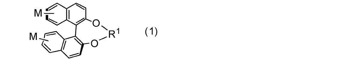
(一般式(1)中、Mはそれぞれ独立に水素原子または置換基を表し、R1は以下に示す連結基のいずれかを表す。

ただし、*は、それぞれ独立に、一般式(1)中の酸素原子との結合部位を表す。R3は、それぞれ独立に、炭素数1から3のアルキル基または炭素数6から10のアリール基を表す。)

(一般式(2)中、R2は以下に示す置換基のいずれかを表し、2つのR2は互いに同じでも異なっていてもよい。

ただし、*は、それぞれ独立に、一般式(2)中の酸素原子との結合部位を表す。Y1はそれぞれ独立に単結合、-O-、-C(=O)O-、-OC(=O)-、または、-OC(=O)O-を表し、Sp1はそれぞれ独立に単結合または炭素数1から8のアルキレン基を表し、Z1はそれぞれ独立に水素原子または(メタ)アクリル基を表し、nは1以上の整数を表す。)

(一般式(3)中、Raは以下に示す連結基のいずれかを表す。

ただし、*は、それぞれ独立に一般式(3)中の酸素原子との結合部位を表す。)

(一般式(4)中、Rbは以下に示す置換基を表し、2つのRbは互いに同じでも異なっていてもよい。

ただし、*は一般式(4)中の酸素原子との結合部位を表し、Y2は単結合、-O-、または、-OC(=O)-を表し、Sp2は単結合または炭素数1から8のアルキレン基を表し、Z2は水素原子または(メタ)アクリル基を表す。)
(In General Formula (1), M represents a hydrogen atom or a substituent each independently, and R < 1 > represents either of the coupling groups shown below.
However, * represents the coupling | bond part with the oxygen atom in General formula (1) each independently. R 3 each independently represents an alkyl group having 1 to 3 carbon atoms or an aryl group having 6 to 10 carbon atoms. )
(In General Formula (2), R 2 represents any of the substituents shown below, and two R 2 s may be the same as or different from each other.
However, * represents the coupling | bond part with the oxygen atom in General formula (2) each independently. Y 1 each independently represents a single bond, —O—, —C (═O) O—, —OC (═O) —, or —OC (═O) O—, and Sp 1 represents each independently a single bond. Represents a bond or an alkylene group having 1 to 8 carbon atoms, Z 1 independently represents a hydrogen atom or a (meth) acryl group, and n represents an integer of 1 or more. )
(In the general formula (3), R a represents any linking groups shown below.
However, * represents the coupling | bond part with the oxygen atom in General formula (3) each independently. )
(In General Formula (4), R b represents a substituent shown below, and two R b s may be the same as or different from each other.
* Represents a bonding site with an oxygen atom in the general formula (4), Y 2 represents a single bond, —O— or —OC (═O) —, and Sp 2 represents a single bond or the number of carbon atoms. 1 to 8 alkylene groups are represented, and Z 2 represents a hydrogen atom or a (meth) acryl group. )
一般式(1)中、Mは、それぞれ独立に、水素原子または置換基を表す。なかでも、Mとしては、水素原子、ハロゲン原子、炭素数1~12のアルキル基、アルキニル基、アルケニル基、または、アルキルオキシ基が好ましい。なお、各基の中のCH2基は、それぞれ独立に、O、S、OCO、COO、OCOO、COまたはフェニレン基で置換されてもよい。
ここで、炭素数1~12のアルキル基、アルキニル基、アルケニル基、または、アルキルオキシ基の中のCH2基が、O、S、OCO、COO、OCOO、COまたはフェニレン基で置換される場合、置換されるCH2基の位置は、各基の末端であっても、各基の内部であってもよい。例えば、炭素数1のアルキル基がフェニレン基で置換されるとMは実質的にフェニル基を表すこととなり、例えば、炭素数3のアルキル基がCOで置換されるとMは実質的にエチルカルボニル基を表すこととなり、例えば、炭素数4のアルキル基がSで置換されるとMは実質的にプロピルチオ基を表すこととなるが、これらの置換基はいずれも一般式(1)を満たすMに含まれる。 The compound represented by the general formula (1) will be described.
In general formula (1), M represents a hydrogen atom or a substituent each independently. Among these, M is preferably a hydrogen atom, a halogen atom, an alkyl group having 1 to 12 carbon atoms, an alkynyl group, an alkenyl group, or an alkyloxy group. The CH 2 group in each group may be independently substituted with an O, S, OCO, COO, OCOO, CO or phenylene group.
Here, when the CH 2 group in the alkyl group, alkynyl group, alkenyl group or alkyloxy group having 1 to 12 carbon atoms is substituted with an O, S, OCO, COO, OCOO, CO or phenylene group The position of the substituted CH 2 group may be at the end of each group or inside each group. For example, when an alkyl group having 1 carbon atom is substituted with a phenylene group, M substantially represents a phenyl group. For example, when an alkyl group having 3 carbon atoms is substituted with CO, M is substantially ethylcarbonyl. For example, when an alkyl group having 4 carbon atoms is substituted with S, M substantially represents a propylthio group, and these substituents are all M satisfying the general formula (1). include.
CH2基がSにより置換されている炭素数1~12のアルキル基としては、例えば、メチルチオ基、エチルチオ基、プロピルチオ基、ブチルチオ基、ペンチルチオ基、ヘキシルチオ基、ヘプチルチオ基、オクチルチオ基、ノニルチオ基、デシルチオ基、および、ウンデシルチオ基が挙げられる。
CH2基がOCOまたはCOOにより置換されている炭素数1~12のアルキル基としては、好ましくは、直鎖状であり、2~6個のC原子を有する基である。具体的には、アセチルオキシ基、プロピオニルオキシ基、ブチリルオキシ基、ペンタノイルオキシ基、ヘキサノイルオキシ基、アセチルオキシメチル基、プロピオニルオキシメチル基、ブチリルオキシメチル基、ペンタノイルオキシメチル基、2-アセチルオキシエチル基、2-プロピオニルオキシエチル基、2-ブチリルオキシエチル基、3-アセチルオキシプロピル基、3-プロピオニルオキシプロピル基、4-アセチルオキシブチル基、メトキシカルボニル基、エトキシカルボニル基、プロポキシカルボニル基、ブトキシカルボニル基、ペントキシカルボニル基、メトキシカルボニルメチル基、エトキシカルボニルメチル基、プロポキシカルボニルメチル基、ブトキシカルボニルメチル基、2-(メトキシカルボニル)エチル基、2-(エトキシカルボニル)エチル基、2-(プロポキシカルボニル)エチル基、3-(メトキシカルボニル)プロピル基、3-(エトキシカルボニル)プロピル基、および、4-(メトキシカルボニル)-ブチル基が挙げられる。
CH2基がOCOOにより置換されている炭素数1~12のアルキル基としては、直鎖状であっても分枝状であってもよいが、直鎖状が好ましく、公知の基を用いることがきる。
CH2基がCOにより置換されている炭素数1~12のアルキル基としては、例えば、カルボニルメチル基、カルボニルエチル基、カルボニルプロピル基、カルボニルブチル基、カルボニルペンチル基、カルボニルヘキシル基、カルボニルヘプチル基、カルボニルオクチル基、カルボニルノニル基、カルボニルデシル基、および、カルボニルウンデシル基が挙げられる。
CH2基がフェニレンにより置換されている炭素数1~12のアルキル基としては、フェニル基が挙げられる。 Examples of the alkyl group having 1 to 12 carbon atoms in which the CH 2 group is substituted by O include a 2-oxapropyl (= methoxymethyl) group, 2-(= ethoxymethyl) or 3-oxabutyl (= 2-methoxy). Ethyl) group, 2-, 3- or 4-oxapentyl group, 2-, 3-, 4- or 5-oxahexyl group, 2-, 3-, 4-, 5- or 6-oxaheptyl group, 2 -, 3-, 4-, 5-, 6- or 7-oxaoctyl group, 2-, 3-, 4-, 5-, 6-, 7- or 8-oxanonyl group, and 2-, 3- , 4-, 5-, 6-, 7-, 8- or 9-oxadecyl group.
Examples of the alkyl group having 1 to 12 carbon atoms in which the CH 2 group is substituted by S include, for example, methylthio group, ethylthio group, propylthio group, butylthio group, pentylthio group, hexylthio group, heptylthio group, octylthio group, nonylthio group, A decylthio group and an undecylthio group are mentioned.
The alkyl group having 1 to 12 carbon atoms in which the CH 2 group is substituted by OCO or COO is preferably a linear group having 2 to 6 C atoms. Specifically, acetyloxy group, propionyloxy group, butyryloxy group, pentanoyloxy group, hexanoyloxy group, acetyloxymethyl group, propionyloxymethyl group, butyryloxymethyl group, pentanoyloxymethyl group, 2- Acetyloxyethyl group, 2-propionyloxyethyl group, 2-butyryloxyethyl group, 3-acetyloxypropyl group, 3-propionyloxypropyl group, 4-acetyloxybutyl group, methoxycarbonyl group, ethoxycarbonyl group, propoxy Carbonyl group, butoxycarbonyl group, pentoxycarbonyl group, methoxycarbonylmethyl group, ethoxycarbonylmethyl group, propoxycarbonylmethyl group, butoxycarbonylmethyl group, 2- (methoxycarbonyl) ethyl group, 2- Ethoxycarbonyl) ethyl group, 2- (propoxycarbonyl) ethyl group, 3- (methoxycarbonyl) propyl group, 3- (ethoxycarbonyl) propyl, and 4- (methoxycarbonyl) - and a butyl group.
The alkyl group having 1 to 12 carbon atoms in which the CH 2 group is substituted by OCOO may be linear or branched, but is preferably linear and a known group is used. I'm going.
Examples of the alkyl group having 1 to 12 carbon atoms in which the CH 2 group is substituted by CO include, for example, a carbonylmethyl group, a carbonylethyl group, a carbonylpropyl group, a carbonylbutyl group, a carbonylpentyl group, a carbonylhexyl group, and a carbonylheptyl group. Carbonyloctyl group, carbonylnonyl group, carbonyldecyl group, and carbonylundecyl group.
Examples of the alkyl group having 1 to 12 carbon atoms in which the CH 2 group is substituted with phenylene include a phenyl group.
CH2基が複数の同種または異種のO、S、OCO、COO、OCOO、COまたはフェニレン基で置換されている炭素数1~12のアルキル基としては、例えば、アルキルフェニルカルボニル基、アルキルフェニルオキシカルボニル基、アルキルフェニルカルボニルオキシ基、アルコキシフェニルカルボニル基、アルコキシフェニルオキシカルボニル基、アルコキシフェニルカルボニルオキシ基、アルキルチオフェニルカルボニル基、アルキルチオフェニルオキシカルボニル基、および、アルキルチオフェニルカルボニルオキシ基が挙げられる。 Further, the CH 2 group in the alkyl group, alkynyl group, alkenyl group, or alkyloxy group having 1 to 12 carbon atoms may be a plurality of the same or different O, S, OCO, COO, OCOO, CO, or phenylene groups. May be substituted.
Examples of the alkyl group having 1 to 12 carbon atoms in which the CH 2 group is substituted with a plurality of the same or different O, S, OCO, COO, OCOO, CO or phenylene groups include, for example, an alkylphenylcarbonyl group, alkylphenyloxy Examples include carbonyl group, alkylphenylcarbonyloxy group, alkoxyphenylcarbonyl group, alkoxyphenyloxycarbonyl group, alkoxyphenylcarbonyloxy group, alkylthiophenylcarbonyl group, alkylthiophenyloxycarbonyl group, and alkylthiophenylcarbonyloxy group.
なお、上述したように、上記アルキル基、アルキニル基、アルケニル基、および、アルキルオキシ基は、その中のCH2基はそれぞれ独立にO、S、OCO、COO、OCOO、COまたはフェニレン基で置換されてもよい。
M中、水素原子以外の置換基の数は0~4個であることが好ましく、0~2個であることがより好ましく、0個であることがさらに好ましい。
一般式(1)中、Mがいずれも水素原子を示すことが、高いHTPと合成容易性の両立の観点から好ましい。 In general formula (1), M is preferably a hydrogen atom, a fluorine atom, a bromine atom, an alkyl group having 1 to 12 carbon atoms, an alkynyl group, an alkenyl group, or an alkyloxy group independently of each other. More preferably a fluorine atom, a bromine atom, an alkyl group having 1 to 8 carbon atoms, an alkynyl group, an alkenyl group, or an alkyloxy group, a hydrogen atom, a fluorine atom, a bromine atom, an alkyl having 1 to 4 carbon atoms. More preferably, it is a group, an alkynyl group, an alkenyl group or an alkyloxy group.
As described above, the alkyl group, an alkynyl group, an alkenyl group, and the alkyl group is substituted in each CH 2 group therein independently O, S, OCO, COO, OCOO, with CO or a phenylene group May be.
In M, the number of substituents other than hydrogen atoms is preferably 0 to 4, more preferably 0 to 2, and even more preferably 0.
In general formula (1), it is preferable that M represents a hydrogen atom from the viewpoint of achieving both high HTP and ease of synthesis.

(ただし、*は、それぞれ独立に、一般式(1)中の酸素原子との結合部位を表す。R3はそれぞれ独立に炭素数1から3のアルキル基または炭素数6から10のアリール基を表す)のいずれかを表し、この中でも、

を表すことが好ましい。
R3は、それぞれ独立に炭素数1から3のアルキル基またはフェニル基であることが好ましく、アルキル基、アリール基、または、アルケニル基であることがより好ましい。 In general formula (1), R 1 is a linking group shown below.
(However, * each independently represents a bonding site with an oxygen atom in the general formula (1). R 3 independently represents an alkyl group having 1 to 3 carbon atoms or an aryl group having 6 to 10 carbon atoms. Represent one), and among these,
Is preferably represented.
R 3 is preferably each independently an alkyl group having 1 to 3 carbon atoms or a phenyl group, and more preferably an alkyl group, an aryl group, or an alkenyl group.

(一般式(3)中、Raは以下に示す連結基のいずれかを表す。

ただし*はそれぞれ一般式(3)中の酸素原子との結合部位を表す。) The compound represented by the general formula (1) is preferably a compound represented by the following general formula (3).
(In the general formula (3), R a represents any linking groups shown below.
However, * represents the coupling | bond part with the oxygen atom in General formula (3), respectively. )

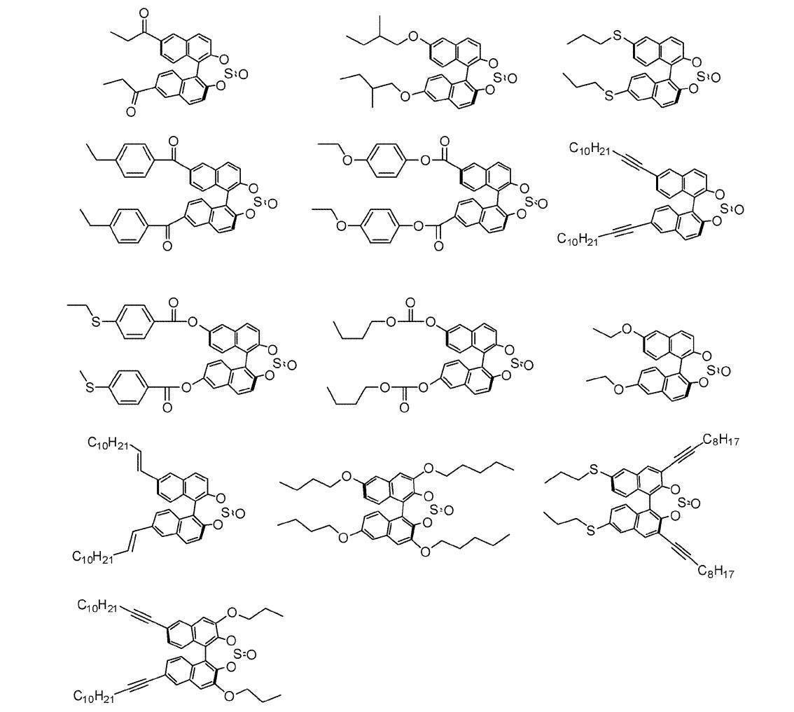
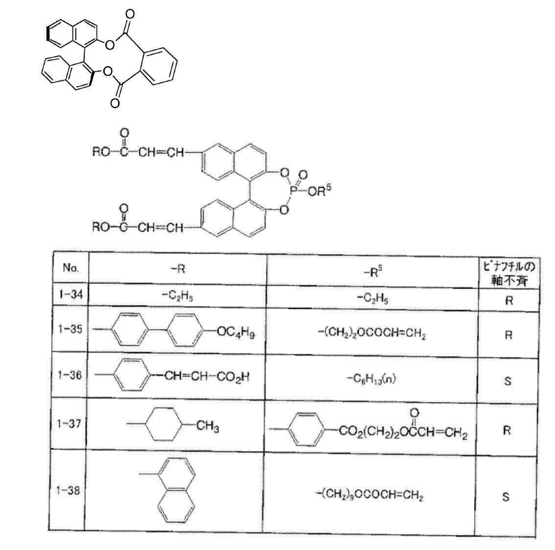
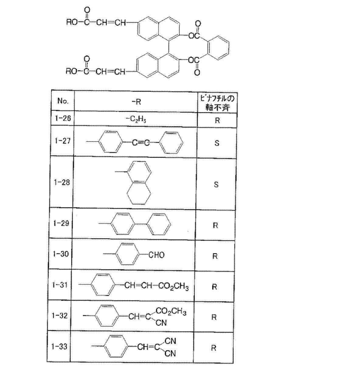
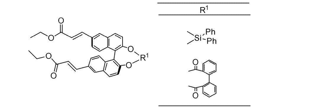
また、一般式(1)で表される化合物のR体とS体は、それぞれ原料としてR体のみまたはS体のみの原料を用いて、合成することができる。その他、公知の方法によりラセミ体を光学分割してもよい。 The compound represented by the general formula (1) can be synthesized by a method described in known literature or in the same manner. For example, Heteroatom Chemistry, 2011 vol. 22, p. It is preferable to synthesize by the method described in 562.
In addition, the R-form and S-form of the compound represented by the general formula (1) can be synthesized by using only the R-form or the S-form of the raw material, respectively. In addition, the racemate may be optically resolved by a known method.

一般式(2)中、R2は以下に示す置換基のいずれかを表し、2つのR2は互いに同じでも異なっていてもよい。

ただし、*は、それぞれ独立に一般式(2)中の酸素原子との結合部位を表す。
Y1は、それぞれ独立に、単結合、-O-、-C(=O)O-、-OC(=O)-、または、-OC(=O)O-を表し、単結合、-O-、または、-OC(=O)-であることが好ましく、-O-であることがより好ましい。
Sp1は、それぞれ独立に、単結合または炭素数1~8のアルキレン基を表し、炭素数1~5のアルキレン基であることが好ましく、炭素数2~4のアルキレン基であることがより好ましい。
Z1は、それぞれ独立に、水素原子または(メタ)アクリル基を表し、水素原子であることが好ましい。
nは1以上の整数を表し、1~3であることが好ましく、1または2であることがより好ましく、1であることがさらに好ましい。
In the general formula (2), R 2 represents any of the following substituents, and the two R 2 may be the same or different from each other.
However, * represents the coupling | bond part with the oxygen atom in General formula (2) each independently.
Y 1 each independently represents a single bond, —O—, —C (═O) O—, —OC (═O) —, or —OC (═O) O—, a single bond, —O — Or —OC (═O) — is preferable, and —O— is more preferable.
Sp 1 each independently represents a single bond or an alkylene group having 1 to 8 carbon atoms, preferably an alkylene group having 1 to 5 carbon atoms, and more preferably an alkylene group having 2 to 4 carbon atoms. .
Z 1 each independently represents a hydrogen atom or a (meth) acryl group, and is preferably a hydrogen atom.
n represents an integer of 1 or more, preferably 1 to 3, more preferably 1 or 2, and still more preferably 1.
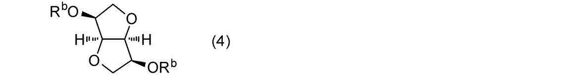
一般式(4)中、Rbは以下に示す置換基を表し、2つのRbは互いに同じでも異なっていてもよいが、同じであることが好ましい。
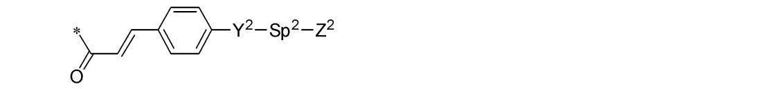
上記置換基中、*は一般式(4)中の酸素原子との結合部位を表す。
Y2は、単結合、-O-、または、-OC(=O)-を表し、-O-であることが好ましい。
Sp2は単結合または炭素数1~8のアルキレン基を表し、炭素数1~8のアルキレン基であることが好ましく、炭素数1~5のアルキレン基であることがより好ましく、炭素数2~4のアルキレン基であることがさらに好ましい。
Z2は水素原子または(メタ)アクリル基を表し、水素原子であることが好ましい。 The compound represented by the general formula (2) is preferably a compound represented by the following general formula (4).
In General Formula (4), R b represents a substituent shown below, and two R b may be the same or different from each other, but are preferably the same.
In the above substituents, * represents a bonding site with an oxygen atom in the general formula (4).
Y 2 represents a single bond, —O— or —OC (═O) —, and is preferably —O—.
Sp 2 represents a single bond or an alkylene group having 1 to 8 carbon atoms, preferably an alkylene group having 1 to 8 carbon atoms, more preferably an alkylene group having 1 to 5 carbon atoms, and 2 to More preferably, it is an alkylene group of 4.
Z 2 represents a hydrogen atom or a (meth) acryl group, and is preferably a hydrogen atom.


組成物には、配向制御剤が含まれていてもよい。
配向制御剤の好ましい例としては、フッ素系配向制御剤が挙げられる。また、2種以上の配向制御剤を含んでいてもよい。フッ素系配向制御剤は、光反射層の空気界面において、液晶化合物の分子のチルト角を低減または実質的に水平配向させることができる。
なお、本明細書で「水平配向」とは、液晶分子長軸と膜面が平行であることをいうが、厳密に平行であることを要求するものではなく、本明細書では、水平面とのなす傾斜角が20度未満の配向を意味するものとする。液晶化合物が空気界面付近で水平配向する場合、配向欠陥が生じ難いため、可視光線領域での透明性が高くなり、また赤外線領域での反射率が増大する。一方、液晶化合物の分子が小さいチルト角で配向すると、コレステリック液晶相の螺旋軸が膜面法線からずれにくく、反射率の低下が抑制され、かつ、フィンガープリントパターンの発生も抑制される。
配向制御剤としては、特開2005-99248号公報の段落0092および0093中に例示されている化合物、特開2002-129162号公報の段落0076~0078および段落0082~0085中に例示されている化合物、特開2005-99248号公報の段落0094および0095中に例示されている化合物、および、特開2005-99248号公報の段落0096中に例示されている化合物が挙げられる。
フッ素系配向制御剤として、下記一般式(I)で表される化合物も好ましい。 (Orientation control agent)
The composition may contain an orientation control agent.
Preferable examples of the alignment control agent include a fluorine-based alignment control agent. Two or more kinds of alignment control agents may be included. The fluorine-based alignment control agent can reduce the tilt angle of the molecules of the liquid crystal compound or substantially horizontally align it at the air interface of the light reflecting layer.
In the present specification, “horizontal alignment” means that the major axis of the liquid crystal molecule is parallel to the film surface, but it is not required to be strictly parallel. An orientation with an inclination angle of less than 20 degrees is meant. When the liquid crystal compound is horizontally aligned in the vicinity of the air interface, alignment defects are unlikely to occur, so that transparency in the visible light region is increased and reflectance in the infrared region is increased. On the other hand, when the molecules of the liquid crystal compound are aligned at a small tilt angle, the helical axis of the cholesteric liquid crystal phase is unlikely to deviate from the film surface normal, and the decrease in reflectance is suppressed, and the occurrence of a fingerprint pattern is also suppressed.
Examples of the orientation control agent include compounds exemplified in paragraphs 0092 and 0093 of JP-A-2005-99248, and compounds exemplified in paragraphs 0076 to 0078 and paragraphs 0082 to 0085 of JP-A-2002-129162. And compounds exemplified in paragraphs 0094 and 0095 of JP-A-2005-99248 and compounds exemplified in paragraph 0096 of JP-A-2005-99248.
A compound represented by the following general formula (I) is also preferred as the fluorine-based alignment control agent.
但し、アルキレン基の水素原子はフッ素原子で置換されていてもよい。アルキレン基には、分枝があってもなくてもよいが、好ましいのは直鎖状のアルキレン基である。合成上の観点からは、Sp11とSp14とが同一であり、かつ、Sp12とSp13とが同一であることが好ましい。 Sp 11 , Sp 12 , Sp 13 and Sp 14 each independently represent a single bond or an alkylene group having 1 to 10 carbon atoms, preferably a single bond or an alkylene group having 1 to 7 carbon atoms, Alternatively, an alkylene group having 1 to 4 carbon atoms is more preferable.
However, the hydrogen atom of the alkylene group may be substituted with a fluorine atom. The alkylene group may or may not be branched, but a linear alkylene group is preferred. From the viewpoint of synthesis, it is preferable that Sp 11 and Sp 14 are the same, and Sp 12 and Sp 13 are the same.
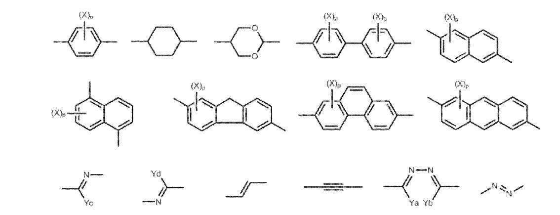
で表される二価の基または二価の芳香族複素環基を表す(上記T11中に含まれるXは、炭素数1~8のアルキル基、アルコキシ基、ハロゲン原子、シアノ基またはエステル基を表し、Ya、Yb、Yc、および、Ydはそれぞれ独立して水素原子または炭素数1~4のアルキル基を表す)ことが好ましく、より好ましくは
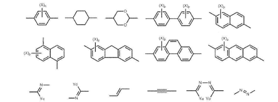
であり、さらに好ましくは

であり、特に好ましくは、

である。
上記T11中に含まれるXがとりうるアルキル基の炭素数は1~8であり、1~5であることが好ましく、1~3であることがより好ましい。アルキル基は、直鎖状、分枝状、および、環状のいずれであってもよく、直鎖状または分枝状であることが好ましい。好ましいアルキル基としては、メチル基、エチル基、n-プロピル基、および、イソプロピル基が挙げられ、メチル基が好ましい。上記T11中に含まれるXがとりうるアルコキシ基のアルキル部分については、上記T11中に含まれるXがとりうるアルキル基の説明と好ましい範囲を参照することができる。上記T11中に含まれるXがとりうるハロゲン原子としては、フッ素原子、塩素原子、臭素原子、および、ヨウ素原子が挙げられ、塩素原子、または、臭素原子が好ましい。上記T11中に含まれるXがとりうるエステル基としては、R’COO-で表される基が挙げられる。R’としては、炭素数1~8のアルキル基が挙げられる。R’がとりうるアルキル基の説明と好ましい範囲については、上記T11中に含まれるXがとりうるアルキル基の説明と好ましい範囲を参照することができる。エステルの具体例として、CH3COO-、および、C2H5COO-が挙げられる。Ya、Yb、Yc、および、Ydがとりうる炭素数1~4のアルキル基は、直鎖状であっても分枝状であってもよい。例えば、メチル基、エチル基、n-プロピル基、および、イソプロピル基が挙げられる。
二価の芳香族複素環基は、5員、6員または7員の複素環を有することが好ましくい。なかでも、5員環または6員環がより好ましく、6員環がさらに好ましい。複素環を構成する複素原子としては、窒素原子、酸素原子、または、硫黄原子が好ましい。複素環は、芳香族性複素環であることが好ましい。芳香族性複素環は、一般に不飽和複素環である。最多二重結合を有する不飽和複素環がより好ましい。複素環としては、フラン環、チオフェン環、ピロール環、ピロリン環、ピロリジン環、オキサゾール環、イソオキサゾール環、チアゾール環、イソチアゾール環、イミダゾール環、イミダゾリン環、イミダゾリジン環、ピラゾール環、ピラゾリン環、ピラゾリジン環、トリアゾール環、フラザン環、テトラゾール環、ピラン環、チイン環、ピリジン環、ピペリジン環、オキサジン環、モルホリン環、チアジン環、ピリダジン環、ピリミジン環、ピラジン環、ピペラジン環、および、トリアジン環が挙げられる。二価の複素環基は置換基を有していてもよい。そのような置換基の例の説明と好ましい範囲については、上記のA1とA2の3価または4価の芳香族炭化水素が取り得る置換基に関する説明と記載を参照することができる。 T 11 is
(X in T 11 is an alkyl group having 1 to 8 carbon atoms, an alkoxy group, a halogen atom, a cyano group, or an ester group. And Ya, Yb, Yc, and Yd each independently represents a hydrogen atom or an alkyl group having 1 to 4 carbon atoms, and more preferably
And more preferably
And particularly preferably,
It is.
The alkyl group that X contained in T 11 can have 1 to 8 carbon atoms, preferably 1 to 5 carbon atoms, and more preferably 1 to 3 carbon atoms. The alkyl group may be linear, branched, or cyclic, and is preferably linear or branched. Preferred alkyl groups include a methyl group, an ethyl group, an n-propyl group, and an isopropyl group, and a methyl group is preferred. The alkyl moiety of the alkoxy group X contained in the T 11 can be taken, it is possible to refer to the description and the preferred range of the alkyl group X contained in the T 11 can take. Examples of the halogen atom that X contained in T 11 can take include a fluorine atom, a chlorine atom, a bromine atom, and an iodine atom, and a chlorine atom or a bromine atom is preferable. Examples of the ester group that X contained in T 11 can take include a group represented by R′COO—. R ′ includes an alkyl group having 1 to 8 carbon atoms. For the explanation and preferred range of the alkyl group that R ′ can take, reference can be made to the explanation and preferred range of the alkyl group that X contained in T 11 can take. Specific examples of the ester include CH 3 COO— and C 2 H 5 COO—. The alkyl group having 1 to 4 carbon atoms that can be taken by Ya, Yb, Yc, and Yd may be linear or branched. Examples thereof include a methyl group, an ethyl group, an n-propyl group, and an isopropyl group.
The divalent aromatic heterocyclic group preferably has a 5-membered, 6-membered or 7-membered heterocyclic ring. Among these, a 5-membered ring or a 6-membered ring is more preferable, and a 6-membered ring is more preferable. As the hetero atom constituting the heterocyclic ring, a nitrogen atom, an oxygen atom, or a sulfur atom is preferable. The heterocycle is preferably an aromatic heterocycle. The aromatic heterocycle is generally an unsaturated heterocycle. An unsaturated heterocyclic ring having the most double bonds is more preferable. As the heterocyclic ring, furan ring, thiophene ring, pyrrole ring, pyrroline ring, pyrrolidine ring, oxazole ring, isoxazole ring, thiazole ring, isothiazole ring, imidazole ring, imidazoline ring, imidazolidine ring, pyrazole ring, pyrazoline ring, Pyrazolidine ring, triazole ring, furazane ring, tetrazole ring, pyran ring, thiyne ring, pyridine ring, piperidine ring, oxazine ring, morpholine ring, thiazine ring, pyridazine ring, pyrimidine ring, pyrazine ring, piperazine ring, and triazine ring Can be mentioned. The divalent heterocyclic group may have a substituent. For the explanation and preferred ranges of examples of such substituents, reference can be made to the explanations and descriptions regarding the substituents that can be taken by the trivalent or tetravalent aromatic hydrocarbons of A 1 and A 2 .
T11中に含まれるoおよびpは、それぞれ独立に0以上の整数であり、oおよびpが2以上であるとき複数のXは互いに同一であっても異なっていてもよい。T11中に含まれるoは1または2であることが好ましい。T11中に含まれるpは1~4のいずれかの整数であることが好ましく、1または2であることがより好ましい。 m11 and n11 are each independently 0 to 3, and m11 + n11 ≧ 1. In this case, a plurality of parenthesized structures may be the same or different, but are preferably the same. M11 and n11 of the general formula (I) is determined by the valence of A 11 and A 12, the preferred range is also determined by the valency of the preferred range of A 11 and A 12.
O and p contained in T 11 are each independently an integer of 0 or more, and when o and p are 2 or more, a plurality of X may be the same or different from each other. O contained in T 11 is preferably 1 or 2. P contained in T 11 is preferably an integer of 1 to 4, and more preferably 1 or 2.
(CaF2a+1)-(CbH2b)-
(CaF2a+1)-(CbH2b)-O-(CrH2r)-
(CaF2a+1)-(CbH2b)-COO-(CrH2r)-
(CaF2a+1)-(CbH2b)-OCO-(CrH2r)-
上式において、aは2~30であることが好ましく、3~20であることがより好ましく、3~10であることがさらに好ましい。bは0~20であることが好ましく、0~10であることがより好ましく、0~5であることがさらに好ましい。a+bは3~30である。rは1~10であることが好ましく、1~4であることがより好ましい。
また、一般式(I)の末端のHb11-Sp11-L11-Sp12-L12-および-L14-Sp13-L16-Sp14-Hb11は、以下のいずれかの一般式で表される基であることが好ましい。
(CaF2a+1)-(CbH2b)-O
(CaF2a+1)-(CbH2b)-COO-
(CaF2a+1)-(CbH2b)-O-(CrH2r)-O-
(CaF2a+1)-(CbH2b)-COO-(CrH2r)-COO-
(CaF2a+1)-(v)-OCO-(CrH2r)-COO-
上式におけるa、bおよびrの定義は直上の定義と同じである。 The compound represented by the general formula (I) includes the perfluoroalkyl group (Hb 11 ) and the linking group — (— Sp 11 —L 11 —Sp 12 —L 12 ) m 11 —A 11 —L 13 —. and -L 14 -A 12 - (L 15 -Sp 13 -L 16 -Sp 14 -) n 11 -, and is preferably a compound which is a combination of T is a divalent group having the excluded volume effect. The two perfluoroalkyl groups (Hb 11 ) present in the molecule are preferably the same as each other, and the linking group present in the molecule — (— Sp 11 -L 11 -Sp 12 -L 12 ) m 11 -A 11 -L 13 - and -L 14 -A 12 - (L 15 -Sp 13 -L 16 -Sp 14 -) n 11 - is preferably also the same. The terminal Hb 11 -Sp 11 -L 11 -Sp 12 -and -Sp 13 -L 16 -Sp 14 -Hb 11 are preferably groups represented by any one of the following general formulas.
(C a F 2a + 1 )-(C b H 2b )-
(C a F 2a + 1 ) — (C b H 2b ) —O— (C r H 2r ) —
(C a F 2a + 1 ) — (C b H 2b ) —COO— (C r H 2r ) —
(C a F 2a + 1 )-(C b H 2b ) -OCO- (C r H 2r )-
In the above formula, a is preferably from 2 to 30, more preferably from 3 to 20, and even more preferably from 3 to 10. b is preferably 0 to 20, more preferably 0 to 10, and still more preferably 0 to 5. a + b is 3 to 30. r is preferably from 1 to 10, and more preferably from 1 to 4.
Further, Hb 11 -Sp 11 -L 11 -Sp 12 -L 12 -and -L 14 -Sp 13 -L 16 -Sp 14 -Hb 11 at the terminal of the general formula (I) are any of the following general formulas: It is preferable that it is group represented by these.
(C a F 2a + 1 )-(C b H 2b ) -O
(C a F 2a + 1 )-(C b H 2b ) —COO—
(C a F 2a + 1 )-(C b H 2b ) —O— (C r H 2r ) —O—
(C a F 2a + 1 )-(C b H 2b ) —COO— (C r H 2r ) —COO—
(C a F 2a + 1 )-(v) -OCO- (C r H 2r ) -COO-
The definitions of a, b and r in the above formula are the same as the definitions immediately above.
なお、配向制御剤(特に、フッ素系水平配向剤)の含有量を上記範囲に抑える観点から、配向制御剤(特に、フッ素系水平配向剤)がパーフルオロアルキル基を含むことが好ましく、炭素数3~10のパーフルオロアルキル基を含むことがより好ましい。 The content of the alignment control agent (especially the fluorine-based horizontal alignment agent) in the composition is preferably 0.01 to 10% by mass, preferably 0.01 to 5% by mass with respect to the polymerizable liquid crystal compound. More preferably, the content is more preferably 0.01 to 1% by mass, particularly preferably 0.01 to 0.09% by mass, and most preferably 0.01 to 0.06% by mass. preferable.
In addition, from the viewpoint of suppressing the content of the alignment control agent (particularly the fluorine-based horizontal alignment agent) within the above range, the alignment control agent (particularly the fluorine-based horizontal alignment agent) preferably contains a perfluoroalkyl group, and the number of carbon atoms More preferably, it contains 3 to 10 perfluoroalkyl groups.
組成物には、重合開始剤が含まれていてもよい。
例えば、紫外線照射により硬化反応を進行させて光反射層を形成する態様では、使用する重合開始剤は、紫外線照射によって重合反応を開始可能な光重合開始剤であることが好ましい。光重合開始剤としては、例えば、α-カルボニル化合物(米国特許第2367661号、同2367670号の各明細書記載)、アシロインエーテル(米国特許第2448828号明細書記載)、α-炭化水素置換芳香族アシロイン化合物(米国特許第2722512号明細書記載)、多核キノン化合物(米国特許第3046127号、同2951758号の各明細書記載)、トリアリールイミダゾールダイマーとp-アミノフェニルケトンとの組み合わせ(米国特許第3549367号明細書記載)、アクリジンおよびフェナジン化合物(特開昭60-105667号公報、米国特許第4239850号明細書記載)、オキサジアゾール化合物(米国特許第4212970号明細書記載)、並びに、アシルフォスフィンオキシド化合物(特公昭63-40799号公報、特公平5-29234号公報、特開平10-95788号公報、特開平10-29997号公報記載)が挙げられる。
光重合開始剤の使用量は、組成物の全固形分に対して、0.1~20質量%であることが好ましく、1~8質量%であることがより好ましい。 (Polymerization initiator)
The composition may contain a polymerization initiator.
For example, in an embodiment in which a light-reflective layer is formed by causing a curing reaction to proceed by ultraviolet irradiation, the polymerization initiator used is preferably a photopolymerization initiator that can initiate a polymerization reaction by ultraviolet irradiation. Examples of the photopolymerization initiator include α-carbonyl compounds (described in US Pat. Nos. 2,367,661 and 2,367,670), acyloin ether (described in US Pat. No. 2,448,828), α-hydrocarbon substituted aromatics, and the like. Group acyloin compounds (described in US Pat. No. 2,722,512), polynuclear quinone compounds (described in US Pat. Nos. 3,046,127 and 2,951,758), a combination of triarylimidazole dimer and p-aminophenyl ketone (US patent) No. 3549367), acridine and phenazine compounds (JP-A-60-105667, US Pat. No. 4,239,850), oxadiazole compounds (US Pat. No. 4,221,970), and acyl Phosphine oxide compound JP-A-63-40799, JP-B-5-29234, JP-A-10-95788, JP-A-10-29997).
The amount of the photopolymerization initiator used is preferably 0.1 to 20% by mass, more preferably 1 to 8% by mass, based on the total solid content of the composition.
組成物には、溶剤が含まれていてもよい。
溶剤としては、例えば、有機溶剤が好ましく用いられる。有機溶剤としては、アミド(例、N、N-ジメチルホルムアミド)、スルホキシド(例、ジメチルスルホキシド)、ヘテロ環化合物(例、ピリジン)、炭化水素(例、ベンゼン、ヘキサン)、アルキルハライド(例、クロロホルム、ジクロロメタン)、エステル(例、酢酸メチル、酢酸ブチル)、ケトン(例、アセトン、メチルエチルケトン、シクロヘキサノン)、および、エーテル(例、テトラヒドロフラン、1、2-ジメトキシエタン)が挙げられる。なかでも、アルキルハライドおよびケトンが好ましい。2種類以上の有機溶剤を併用してもよい。 (solvent)
The composition may contain a solvent.
For example, an organic solvent is preferably used as the solvent. Examples of organic solvents include amides (eg, N, N-dimethylformamide), sulfoxides (eg, dimethyl sulfoxide), heterocyclic compounds (eg, pyridine), hydrocarbons (eg, benzene, hexane), alkyl halides (eg, chloroform). , Dichloromethane), esters (eg, methyl acetate, butyl acetate), ketones (eg, acetone, methyl ethyl ketone, cyclohexanone), and ethers (eg, tetrahydrofuran, 1,2-dimethoxyethane). Of these, alkyl halides and ketones are preferred. Two or more organic solvents may be used in combination.
溶剤から金属等の不純物を除去する方法としては、例えば、蒸留(分子蒸留または薄膜蒸留等)、および、フィルターを用いた濾過を挙げることができる。フィルターを用いたろ過におけるフィルター孔径としては、ポアサイズ10nm以下が好ましく、5nm以下がより好ましく、3nm以下がさらに好ましい。フィルターとしては、ポリテトラフロロエチレン製、ポリエチレン製、または、ナイロン製のフィルターが好ましい。
溶剤は、異性体(同じ原子数で異なる構造の化合物)が含まれていてもよい。また、異性体は、1種のみが含まれていてもよいし、複数種含まれていてもよい。 In the present invention, it is preferable to use a solvent having a low metal content, and the metal content of the solvent is preferably 10 ppb or less, for example. A ppt level solvent may be used as necessary, and such a high-purity solvent is provided by Toyo Gosei Co., Ltd., for example.
Examples of the method for removing impurities such as metals from the solvent include distillation (molecular distillation or thin film distillation, etc.) and filtration using a filter. The filter pore size in filtration using a filter is preferably 10 nm or less, more preferably 5 nm or less, and even more preferably 3 nm or less. As the filter, a filter made of polytetrafluoroethylene, polyethylene, or nylon is preferable.
The solvent may contain isomers (compounds having the same number of atoms and different structures). Moreover, only 1 type may be included and the isomer may be included multiple types.
組成物には、上述した成分に加えて、他の添加剤(例えば、界面活性剤、アルコキシシリル基を有する化合物、セルロースエステル)が含まれていてもよい。
なお、界面活性剤およびアルコキシシリル基を有する化合物の具体的な種類としては、後述する(赤外線透過組成物の第1の実施の形態)に含まれる界面活性剤およびアルコキシシリル基を有する化合物で例示されるものが挙げられる。 (Other ingredients)
In addition to the components described above, the composition may contain other additives (for example, a surfactant, a compound having an alkoxysilyl group, and a cellulose ester).
Specific examples of the surfactant and the compound having an alkoxysilyl group are exemplified by the surfactant and the compound having an alkoxysilyl group, which will be described later (the first embodiment of the infrared transmitting composition). What is done.
光反射層(光反射層Xaおよび光反射層Xb)の形成方法は特に制限されないが、上述したように、重合性基を有する液晶化合物およびキラル剤を含む組成物を用いる方法が挙げられる。
以下は、上記組成物を用いた方法について詳述する。なお、光反射層Xaを形成する際にはキラル剤として右旋回性のキラル剤が用いられ、光反射層Xbを形成する際にはキラル剤として左旋回性のキラル剤が用いられるが、以下の説明では、単に「キラル剤」と表記して説明を行う。 (Method for forming light reflecting layer)
Although the formation method in particular of a light reflection layer (light reflection layer Xa and light reflection layer Xb) is not restrict | limited, As mentioned above, the method of using the composition containing the liquid crystal compound which has a polymeric group, and a chiral agent is mentioned.
Hereinafter, a method using the above composition will be described in detail. In addition, when forming the light reflection layer Xa, a right-turning chiral agent is used as the chiral agent, and when forming the light reflection layer Xb, a left-turning chiral agent is used as the chiral agent. In the following description, it will be described simply as “chiral agent”.
(1) 基板の表面に、重合性基を有する液晶化合物およびキラル剤を含む組成物を塗布して塗膜を形成し、その後、塗膜をコレステリック液晶相の状態にする工程
(2) 塗膜に対して光照射して硬化反応を進行させ、コレステリック液晶相を固定して光反射層を形成する工程
(1)および(2)の工程を、基板の一方の表面上で2回繰り返すことで図1に示す構成と同様の構成の積層体を作製することができる。
なお、コレステリック液晶相の旋回の方向は、用いる液晶の種類または添加されるキラル剤の種類によって調整でき、螺旋ピッチ(すなわち、選択反射波長)は、これらの材料の濃度によって任意に調整できる。また、各光反射層の反射する光の波長は、製造方法のさまざまな要因によってシフトさせることができ、キラル剤等の添加濃度のほか、コレステリック液晶相を固定するときの温度、照度、および、照射時間等の条件等でシフトさせることができる。 The method for forming the light reflecting layer preferably includes the following steps (1) and (2).
(1) A step of applying a composition containing a liquid crystal compound having a polymerizable group and a chiral agent to the surface of a substrate to form a coating film, and then bringing the coating film into a cholesteric liquid crystal phase (2) The step (1) and the step (2) of forming a light reflecting layer by fixing the cholesteric liquid crystal phase by irradiating with light is repeated twice on one surface of the substrate. A stacked body having a structure similar to that shown in FIG. 1 can be manufactured.
Note that the direction of rotation of the cholesteric liquid crystal phase can be adjusted by the type of liquid crystal used or the type of chiral agent added, and the helical pitch (ie, selective reflection wavelength) can be arbitrarily adjusted by the concentration of these materials. In addition, the wavelength of light reflected by each light reflecting layer can be shifted depending on various factors of the manufacturing method, in addition to the addition concentration of a chiral agent, etc., temperature, illuminance when fixing the cholesteric liquid crystal phase, and It can be shifted depending on conditions such as irradiation time.
組成物の塗布は、ワイヤーバーコーティング法、押し出しコーティング法、ダイレクトグラビアコーティング法、リバースグラビアコーティング法、ダイコーティング法、および、スピンコート法等の種々の方法によって行うことができる。また、インクジェット装置を用いて、組成物をノズルから吐出して、塗膜を形成することもできる。 In the step (1), first, a composition containing a liquid crystal compound having a polymerizable group and a chiral agent is applied to the surface of the substrate.
The composition can be applied by various methods such as a wire bar coating method, an extrusion coating method, a direct gravure coating method, a reverse gravure coating method, a die coating method, and a spin coating method. In addition, a coating film can be formed by discharging the composition from a nozzle using an ink jet apparatus.
紫外線の照射エネルギー量については特に制限はないが、一般的には、100~800mJ/cm2程度が好ましい。また、塗膜に紫外線を照射する時間については特に制限はないが、光反射層の充分な強度および生産性の双方の観点から決定される。 Next, at the process of (2), light (for example, ultraviolet-ray) is irradiated to the coating film used as the state of the cholesteric liquid crystal phase, and hardening reaction is advanced. As light irradiation, ultraviolet irradiation is preferable. For ultraviolet irradiation, a light source such as an ultraviolet lamp is used. In this step, by irradiating the coating film with light, the curing reaction of the composition proceeds, the cholesteric liquid crystal phase is fixed, and a light reflecting layer is formed.
The amount of ultraviolet irradiation energy is not particularly limited, but is generally preferably about 100 to 800 mJ / cm 2 . Moreover, although there is no restriction | limiting in particular about the time which irradiates a coating film with an ultraviolet-ray, It determines from the viewpoint of both sufficient intensity | strength and productivity of a light reflection layer.
また、光照射時の雰囲気の酸素濃度は、重合度に関与する場合がある。そのため、空気中で所望の重合度に達せず、膜強度が不十分の場合には、窒素置換等の方法により、雰囲気中の酸素濃度を低下させることが好ましい。酸素濃度としては、10%以下が好ましく、7%以下がより好ましく、3%以下がさらに好ましい。光照射によって進行される硬化反応(例えば重合反応)の反応率は、光反射層の機械的強度の保持等および未反応物が層から流出するのを抑える等の観点から、70%以上であることが好ましく、80%以上であることがより好ましく、90%以上であることがさらに好ましい。反応率を向上させるためには照射する光の照射量を増大する方法、および、窒素雰囲気下または加熱条件下での重合が効果的である。また、一旦重合させた後に、重合温度よりも高温状態で保持して熱重合反応によって反応をさらに推し進める方法、および、再度、光(例えば、紫外線)を照射する(ただし、本発明の条件を満足する条件で照射する)方法を用いることもできる。反応率の測定は反応性基(例えば重合性基)の赤外振動スペクトルの吸収強度を、反応進行の前後で比較することによって行うことができる。 In order to accelerate the curing reaction, light irradiation may be performed under heating conditions. Moreover, it is preferable to maintain the temperature at the time of light irradiation in the temperature range which exhibits a cholesteric liquid crystal phase so that a cholesteric liquid crystal phase may not be disturbed.
Moreover, the oxygen concentration of the atmosphere at the time of light irradiation may be related to the degree of polymerization. Therefore, when the desired degree of polymerization is not achieved in air and the film strength is insufficient, it is preferable to reduce the oxygen concentration in the atmosphere by a method such as nitrogen substitution. The oxygen concentration is preferably 10% or less, more preferably 7% or less, and even more preferably 3% or less. The reaction rate of the curing reaction (for example, polymerization reaction) that proceeds by light irradiation is 70% or more from the viewpoint of maintaining the mechanical strength of the light reflecting layer and suppressing unreacted substances from flowing out of the layer. It is preferably 80% or more, more preferably 90% or more. In order to improve the reaction rate, a method of increasing the irradiation amount of light to be irradiated and polymerization under a nitrogen atmosphere or heating conditions are effective. In addition, after polymerization, the reaction is further continued by a thermal polymerization reaction while being held at a temperature higher than the polymerization temperature, and light (for example, ultraviolet rays) is irradiated again (however, the conditions of the present invention are satisfied) Irradiation method) can also be used. The reaction rate can be measured by comparing the absorption intensity of the infrared vibration spectrum of a reactive group (for example, a polymerizable group) before and after the reaction proceeds.
なお、本発明においては、コレステリック液晶相の光学的性質が層中において保持されていれば十分であり、最終的に各光反射層中の組成物がもはや液晶性を示す必要はない。例えば、組成物が、硬化反応により高分子量化して、もはや液晶性を失っていてもよい。 In the above process, the cholesteric liquid crystal phase is fixed and each light reflecting layer is formed. Here, the state in which the liquid crystal phase is “fixed” is the most typical and preferred mode in which the orientation of the liquid crystal compound in the cholesteric liquid crystal phase is maintained. It is not limited to this, and specifically, this layer usually has no fluidity in the temperature range of 0 to 50 ° C., and -30 to 70 ° C. under severer conditions, and is oriented by an external field and external force. It shall mean a state in which the fixed orientation form can be kept stable without causing a change in form. In the present invention, the alignment state of the cholesteric liquid crystal phase is preferably fixed by a curing reaction that proceeds by ultraviolet irradiation.
In the present invention, it is sufficient that the optical properties of the cholesteric liquid crystal phase are maintained in the layer, and the composition in each light reflecting layer does not need to exhibit liquid crystal properties. For example, the composition may be no longer liquid crystalline due to a high molecular weight due to the curing reaction.
光吸収層は、色材を含んでいる。光吸収層は使用される色材の種類に応じて、所定の波長の光を吸収する層である。
色材(以後、「着色剤」とも称する)の種類は特に制限されず、公知の顔料および染料が挙げられる。なかでも、顔料が好ましい。
光吸収層はバインダーを含んでいてもよく、バインダーの種類は特に制限されず、公知のバインダーを用いることができる。バインダーとしては、例えば、(メタ)アクリル樹脂、スチレン樹脂、ウレタン樹脂、エポキシ樹脂、ポリオレフィン樹脂、ポリカードネート樹脂等が挙げられる。
また、光吸収層に含まれるバインダーは、光吸収層形成用組成物中に重合性化合物を含ませ、この重合性化合物を重合させることにより合成してもよい。また、バインダーとしては、後述する顔料分散剤、および、アルカリ可溶性樹脂が含まれていてもよい。 <Light absorption layer>
The light absorption layer contains a color material. The light absorption layer is a layer that absorbs light of a predetermined wavelength according to the type of color material used.
The type of the color material (hereinafter also referred to as “colorant”) is not particularly limited, and examples thereof include known pigments and dyes. Of these, pigments are preferred.
The light absorption layer may contain a binder, and the kind of the binder is not particularly limited, and a known binder can be used. Examples of the binder include (meth) acrylic resin, styrene resin, urethane resin, epoxy resin, polyolefin resin, and polycarbonate resin.
The binder contained in the light absorbing layer may be synthesized by including a polymerizable compound in the composition for forming the light absorbing layer and polymerizing the polymerizable compound. Moreover, as a binder, the pigment dispersant mentioned later and alkali-soluble resin may be contained.
赤外線透過層とは、所定の波長の赤外線の透過率が高く、所定の波長の可視光線の透過率が低いフィルムをいう。赤外線透過層とは、言い換えれば、赤外線の透過率が高い可視光線吸収層ともいえる。
ここで、所定の波長の赤外線としては、波長700nm以上の領域の電磁波が好ましく挙げられ、波長800mn以上の領域の電磁波がより好ましく挙げられ、波長900nm以上の領域の電磁波がさらに好ましく挙げられる。所定の波長の可視光線とは、波長700nm未満の領域の電磁波がより好ましく挙げられる。なお、上記可視光線の領域の下限値としては、波長400nm以上が好ましい。
透過率が高いとは、最大透過率が70%以上であることを意図し、80%以上が好ましく、90%以上がより好ましい。透過率が低いとは、最大透過率が30%以下であることを意図し、20%以下が好ましく、10%以下がより好ましい。
より具体的には、赤外線透過層としては、波長700nm以上(好ましくは波長800nm以上、より好ましくは波長900nm以上)において最大透過率が70%以下(好ましくは80以上、より好ましくは90%以上)を示し、波長400nm以上700nm未満(好ましくは波長400nm以上波長650nm以下)において最大透過率が30%以下(好ましくは20%以下、より好ましくは10%以下)の赤外線透過層が好ましく挙げられる。 The light absorption layer is preferably an infrared transmission layer.
The infrared transmission layer refers to a film having a high transmittance of infrared rays having a predetermined wavelength and a low transmittance of visible light having a predetermined wavelength. In other words, the infrared transmission layer can be said to be a visible light absorption layer having a high infrared transmittance.
Here, as an infrared ray having a predetermined wavelength, an electromagnetic wave having a wavelength of 700 nm or more is preferably exemplified, an electromagnetic wave having a wavelength of 800 nm or more is more preferred, and an electromagnetic wave having a wavelength of 900 nm or more is more preferred. The visible light having a predetermined wavelength is more preferably an electromagnetic wave having a wavelength of less than 700 nm. The lower limit of the visible light region is preferably a wavelength of 400 nm or more.
High transmittance means that the maximum transmittance is 70% or more, preferably 80% or more, and more preferably 90% or more. Low transmittance means that the maximum transmittance is 30% or less, preferably 20% or less, and more preferably 10% or less.
More specifically, the infrared transmission layer has a maximum transmittance of 70% or less (preferably 80 or more, more preferably 90% or more) at a wavelength of 700 nm or more (preferably a wavelength of 800 nm or more, more preferably a wavelength of 900 nm or more). An infrared transmission layer having a maximum transmittance of 30% or less (preferably 20% or less, more preferably 10% or less) at a wavelength of 400 nm or more and less than 700 nm (preferably a wavelength of 400 nm or more and a wavelength of 650 nm or less) is preferable.
また、色材が顔料である場合、有機顔料であることが好ましく、以下のものを挙げることができる。但し本発明は、これらに限定されるものではない。
カラーインデックス(C.I.)Pigment Yellow 1,2,3,4,5,6,10,11,12,13,14,15,16,17,18,20,24,31,32,34,35,35:1,36,36:1,37,37:1,40,42,43,53,55,60,61,62,63,65,73,74,77,81,83,86,93,94,95,97,98,100,101,104,106,108,109,110,113,114,115,116,117,118,119,120,123,125,126,127,128,129,137,138,139,147,148,150,151,152,153,154,155,156,161,162,164,166,167,168,169,170,171,172,173,174,175,176,177,179,180,181,182,185,187,188,193,194,199,213,214等(以上、黄色顔料)、
C.I.Pigment Orange 2,5,13,16,17:1,31,34,36,38,43,46,48,49,51,52,55,59,60,61,62,64,71,73等(以上、オレンジ色顔料)、
C.I.Pigment Red 1,2,3,4,5,6,7,9,10,14,17,22,23,31,38,41,48:1,48:2,48:3,48:4,49,49:1,49:2,52:1,52:2,53:1,57:1,60:1,63:1,66,67,81:1,81:2,81:3,83,88,90,105,112,119,122,123,144,146,149,150,155,166,168,169,170,171,172,175,176,177,178,179,184,185,187,188,190,200,202,206,207,208,209,210,216,220,224,226,242,246,254,255,264,270,272,279等(以上、赤色顔料)、
C.I.Pigment Green 7,10,36,37,58,59等(以上、緑色顔料)、
C.I.Pigment Violet 1,19,23,27,32,37,42等(以上、紫色顔料)、
C.I.Pigment Blue 1,2,15,15:1,15:2,15:3,15:4,15:6,16,22,60,64,66,79,80等(以上、青色顔料)
これら有機顔料は、単独若しくは種々組合せて用いることができる。 When the color material is a chromatic color, examples of the color material include a red colorant, a green colorant, a blue colorant, a yellow colorant, a purple colorant, and an orange color.
Moreover, when a color material is a pigment, it is preferable that it is an organic pigment, and the following can be mentioned. However, the present invention is not limited to these.
Color Index (CI)
C. I.
C. I.
C. I.
C. I. Pigment Violet 1, 19, 23, 27, 32, 37, 42, etc. (above, purple pigment),
C. I. Pigment Blue 1, 2, 15, 15: 1, 15: 2, 15: 3, 15: 4, 15: 6, 16, 22, 60, 64, 66, 79, 80, etc. (above, blue pigment)
These organic pigments can be used alone or in various combinations.
また、角度依存性をより低減できる点で、上記着色剤Xとともに、波長800~900nmに範囲に極大吸収を有する着色剤Y(色材Y)を用いることがより好ましい。
なお、上記着色剤Xは1種のみを用いてもよいし、2種以上を併用してもよい。 In addition, it is preferable to use the coloring agent X (coloring material X) which has an absorption maximum in the wavelength range of 400 nm or more and less than 700 nm as a coloring material at the point which can reduce angle dependence more.
Further, it is more preferable to use a coloring agent Y (coloring material Y) having a maximum absorption in a wavelength range of 800 to 900 nm together with the coloring agent X from the viewpoint that the angle dependency can be further reduced.
In addition, the said coloring agent X may use only 1 type and may use 2 or more types together.
具体的には、基板上に後述する光吸収層形成用組成物を塗布して、必要に応じて硬化処理を施し、光吸収層を形成する方法が挙げられる。塗布の方法は特に制限されず、スピンコーター、ディップコーター、ダイコーター、スリットコーター、バーコーター、および、グラビアコーター等により塗布する方法が挙げられる。
光吸収層形成用組成物には、少なくとも色材が含まれ、必要に応じて、他の成分(例えば、重合性化合物、バインダー、重合開始剤、顔料分散剤、顔料誘導体、溶剤、界面活性剤、アルカリ可溶性樹脂、および、アルコキシシリル基を有する化合物等)が含まれていてもよい。色材の種類に関しては、後述する(赤外線透過組成物の第1の実施の形態)~(赤外線透過組成物の第9の実施の形態)で述べる色材が挙げられる。また、他の成分に関しても、後述する(赤外線透過組成物の第1の実施の形態)~(赤外線透過組成物の第9の実施の形態)で述べる成分が挙げられる。 A light absorption layer can be formed using the composition for light absorption layer formation containing a coloring material and the component added as needed. In particular, when the light absorbing layer is the infrared ray transmitting layer, it can be formed using an infrared ray transmitting composition containing a predetermined component.
Specifically, a method of forming a light absorption layer by applying a composition for forming a light absorption layer, which will be described later, on a substrate and performing a curing treatment as necessary. The coating method is not particularly limited, and examples thereof include a coating method using a spin coater, a dip coater, a die coater, a slit coater, a bar coater, a gravure coater, and the like.
The composition for forming a light absorption layer contains at least a coloring material, and other components (for example, a polymerizable compound, a binder, a polymerization initiator, a pigment dispersant, a pigment derivative, a solvent, and a surfactant, as necessary. , An alkali-soluble resin, a compound having an alkoxysilyl group, and the like). With respect to the type of the color material, the color materials described in the following (first embodiment of infrared transmitting composition) to (9th embodiment of infrared transmitting composition) can be mentioned. In addition, with respect to the other components, the components described in (First embodiment of infrared transmitting composition) to (Ninth embodiment of infrared transmitting composition) described later can be given.
顔料分散液を得る際の顔料を分散させるプロセスとしては、分散に用いる機械力として圧縮、圧搾、衝撃、剪断、または、キャビテーション等を使用するプロセスが挙げられる。これらプロセスの具体例としては、ビーズミル、サンドミル、ロールミル、ボールミル、ペイントシェーカー、マイクロフルイダイザー、高速インペラー、サンドグラインダー、フロージェットミキサー、高圧湿式微粒化、および、超音波分散等が挙げられる。また、サンドミル(ビーズミル)における顔料の粉砕においては、径の小さいビーズを使用する、ビーズの充填率を大きくする事等により粉砕効率を高めた条件で処理することが好ましく、粉砕処理後に濾過、遠心分離等で素粒子を除去することがより好ましい。
また、「分散技術大全、株式会社情報機構発行、2005年7月15日」や「サスペンション(固/液分散系)を中心とした分散技術と工業的応用の実際 総合資料集、経営開発センター出版部発行、1978年10月10日」、特開2015-157893号公報の段落0022に記載のプロセスおよび分散機を好適に使用できる。
また、顔料分散プロセスにおいては、ソルトミリング工程による顔料の微細化処理を行ってもよい。ソルトミリング工程に用いられる素材、機器、および、処理条件等は、例えば、特開2015-194521号公報、および、特開2012-046629号公報に記載のものを使用することができる。 When a pigment is used as the coloring material, a composition for forming a light absorption layer may be produced by once producing a pigment dispersion and then adding a component such as a polymerizable compound to the pigment dispersion.
Examples of the process for dispersing the pigment when obtaining the pigment dispersion include a process using compression, squeezing, impact, shearing, cavitation or the like as the mechanical force used for dispersion. Specific examples of these processes include bead mill, sand mill, roll mill, ball mill, paint shaker, microfluidizer, high speed impeller, sand grinder, flow jet mixer, high pressure wet atomization, and ultrasonic dispersion. In addition, when pulverizing pigments in a sand mill (bead mill), it is preferable to use beads with small diameters and to increase the pulverization efficiency by increasing the filling rate of beads. More preferably, the elementary particles are removed by separation or the like.
In addition, “Dispersion Technology Encyclopedia, Issued by Information Technology Corporation, July 15, 2005” and “Dispersion Technology Centered on Suspension (Solid / Liquid Dispersion System) and Actual Application of Industrial Application, Collection of Management Development Center” The process and disperser described in Paragraph 0022 of Japanese Patent Application Laid-Open No. 2015-157893 ”can be suitably used.
In the pigment dispersion process, the pigment may be refined by a salt milling process. As materials, equipment, processing conditions and the like used in the salt milling process, for example, those described in JP-A-2015-194521 and JP-A-2012-046629 can be used.
第1の実施の形態の赤外線透過組成物は、一般式(A1)で表される染料と、重合性化合物と、重合開始剤とを含む。赤外線透過組成物は、一般式(A1)で表される染料以外の他の着色剤を含んでいてもよい。また、赤外線透過組成物が顔料を含む場合、顔料分散剤、溶剤、および、顔料誘導体等とともに顔料を分散して、顔料分散液を調製し、得られた顔料分散液を一般式(A1)で表される染料と、重合開始剤と、重合性化合物と混合してもよい。また、赤外線透過組成物は、上記成分以外の他の成分(アルカリ可溶性樹脂、界面活性剤、アルコキシシリル基を有する化合物等)をさらに含んでいてもよい。 (First embodiment of infrared transmitting composition)
The infrared transmitting composition of the first embodiment includes a dye represented by the general formula (A1), a polymerizable compound, and a polymerization initiator. The infrared transmitting composition may contain a colorant other than the dye represented by the general formula (A1). When the infrared transmitting composition contains a pigment, the pigment is dispersed together with a pigment dispersant, a solvent, a pigment derivative, and the like to prepare a pigment dispersion, and the obtained pigment dispersion is represented by the general formula (A1). You may mix with the dye represented, a polymerization initiator, and a polymeric compound. The infrared transmitting composition may further contain other components (alkali-soluble resin, surfactant, compound having an alkoxysilyl group, etc.) other than the above components.
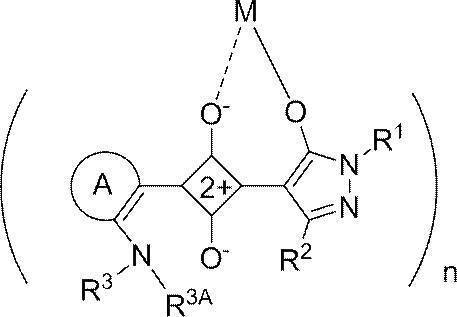
赤外線透過組成物中の一般式(A1)で表される染料の含有量の合計は、15~85質量%が好ましく、20~80質量%がより好ましい。
赤外線透過組成物の全着色剤中、一般式(A1)で表される染料の含有量の合計は、4~50質量%であることが好ましく、7~40質量%であることがより好ましい。
赤外線透過組成物中、一般式(A1)で表される染料は、1種のみ含まれていてもよいし、2種以上含まれていてもよい。2種類以上含む場合は、その合計量が上記範囲となることが好ましい。 In General Formula (A1), R 1 and R 2 each independently represent a hydrogen atom, a halogen atom, a cyano group, a nitro group, a carbonyl group having a substituent, an alkyl group, an aryl group, or a heterocyclic group. . R 3 represents a hydrogen atom, a nitrogen atom, an alkyl group, an aryl group, or a heterocyclic group. R 3 may form a ring with the substituent of A, and when R 3 represents a nitrogen atom, it forms a ring with the substituent of A. R 3A represents a hydrogen atom, an alkyl group, or an aryl group. A represents a hetero 5-membered ring or a hetero 6-membered ring. M represents a metal atom. n represents 2 or 3.
The total content of the dyes represented by formula (A1) in the infrared transmitting composition is preferably 15 to 85% by mass, more preferably 20 to 80% by mass.
In the total colorant of the infrared transmitting composition, the total content of the dye represented by the general formula (A1) is preferably 4 to 50% by mass, and more preferably 7 to 40% by mass.
In the infrared transmitting composition, only one type of dye represented by the general formula (A1) may be included, or two or more types may be included. When two or more types are included, the total amount is preferably within the above range.
赤外線透過組成物は、他の着色剤として黄色顔料と、青色顔料と、紫色顔料とを含むことが好ましい。この場合、赤外線透過組成物中、黄色顔料の全顔料に対する質量比が0.1~0.2であり、青色顔料の全顔料に対する質量比が0.25~0.55であり、紫色顔料の全顔料に対する質量比が0.05~0.15であることが好ましい。また、一般式(A1)で表される染料と黄色顔料との質量比は、85:15~50:50であることが好ましく、一般式(A1)で表される染料と黄色顔料との合計質量と、青色顔料と紫色顔料との合計質量の質量比が、60:40~40:60であることがより好ましい。 Examples of colorants other than the dye represented by formula (A1) include pigments and dyes. Other colorants may be used alone or in combination of two or more. For other colorants, for example, reference can be made to the examples described in JP-A-2013-064999, paragraphs 0019 to 0025, the contents of which are incorporated herein. In particular, PB15: 6 is exemplified as the blue pigment. As a yellow pigment, Pigment Yellow 139 is exemplified. As the purple pigment, Pigment Violet 23 is exemplified.
The infrared transmitting composition preferably contains a yellow pigment, a blue pigment, and a purple pigment as other colorants. In this case, in the infrared transmitting composition, the mass ratio of yellow pigment to all pigments is 0.1 to 0.2, the mass ratio of blue pigment to all pigments is 0.25 to 0.55, The mass ratio with respect to the total pigment is preferably 0.05 to 0.15. The mass ratio of the dye represented by the general formula (A1) and the yellow pigment is preferably 85:15 to 50:50, and the total of the dye represented by the general formula (A1) and the yellow pigment The mass ratio of the mass and the total mass of the blue pigment and the violet pigment is more preferably 60:40 to 40:60.
重合性化合物は、モノマー、ポリマーのいずれの形態であってもよいが、モノマーが好ましい。モノマータイプの重合性化合物は、分子量が200~3000であることが好ましい。分子量の上限は、2500以下がより好ましく、2000以下が更に好ましい。分子量の下限は、250以上がより好ましく、300以上が更に好ましい。 As for the polymerizable compound, for example, the examples described in paragraphs 0466 to 0494 of JP2012-208494A can be referred to, and the contents thereof are incorporated in the present specification. Only 1 type may be used for a polymeric compound and it may use 2 or more types together.
The polymerizable compound may be in the form of either a monomer or a polymer, but is preferably a monomer. The monomer type polymerizable compound preferably has a molecular weight of 200 to 3,000. The upper limit of the molecular weight is more preferably 2500 or less, and still more preferably 2000 or less. The lower limit of the molecular weight is more preferably 250 or more, and still more preferably 300 or more.
また、重合性化合物として、ジグリセリンEO(エチレンオキシド)変性(メタ)アクリレート(市販品としては M-460;東亞合成(株)製)が好ましい。ペンタエリスリトールテトラアクリレート(新中村化学工業(株)製、A-TMMT)、1,6-ヘキサンジオールジアクリレート(日本化薬(株)製、KAYARAD HDDA)も好ましい。これらのオリゴマータイプも使用できる。例えば、RP-1040(日本化薬(株)製)などが挙げられる。 As examples of the polymerizable compound, the description in paragraph numbers 0033 to 0034 of JP2013-253224A can be referred to, and the contents thereof are incorporated in the present specification. Examples of the compound include ethyleneoxy-modified pentaerythritol tetraacrylate (commercially available product is NK ester ATM-35E; manufactured by Shin-Nakamura Chemical Co., Ltd.), dipentaerythritol triacrylate (commercially available product is KAYARAD D-330; Nippon Kayaku Co., Ltd.), dipentaerythritol tetraacrylate (commercially available products are KAYARAD D-320; Nippon Kayaku Co., Ltd.), dipentaerythritol penta (meth) acrylate (commercially available products are KAYARAD D- 310; manufactured by Nippon Kayaku Co., Ltd.), dipentaerythritol hexa (meth) acrylate (commercially available products are KAYARAD DPHA; manufactured by Nippon Kayaku Co., Ltd., A-DPH-12E; manufactured by Shin-Nakamura Chemical Co., Ltd.) ), And these (meth) acryloyl groups are ethyl Glycol, a compound having a structure which is attached via a propylene glycol residue are preferable. These oligomer types can also be used. In addition, the description of polymerizable compounds in paragraph numbers 0034 to 0038 of JP2013-253224A can be referred to, and the contents thereof are incorporated in the present specification. In addition, polymerizable monomers described in paragraph No. 0477 of JP 2012-208494 A (corresponding US Patent Application Publication No. 2012/0235099, [0585]) and the like are described in the present specification. Incorporated into.
As the polymerizable compound, diglycerin EO (ethylene oxide) modified (meth) acrylate (commercially available product is M-460; manufactured by Toagosei Co., Ltd.) is preferable. Pentaerythritol tetraacrylate (manufactured by Shin-Nakamura Chemical Co., Ltd., A-TMMT) and 1,6-hexanediol diacrylate (manufactured by Nippon Kayaku Co., Ltd., KAYARAD HDDA) are also preferable. These oligomer types can also be used. Examples thereof include RP-1040 (manufactured by Nippon Kayaku Co., Ltd.).
市販品としては、ウレタンオリゴマーUAS-10、UAB-140(山陽国策パルプ社製)、UA-7200(新中村化学社製)、DPHA-40H(日本化薬社製)、UA-306H、UA-306T、UA-306I、AH-600、T-600、AI-600、ライトアクリレートDCP―A(共栄社化学(株)製)などが挙げられる。
また、重合性化合物として、アロニックス M-215、M-305、M-313、M-315、TO-2349(東亞合成(株)製)、SR-368(サートマー社製)、A-9300(新中村化学工業(株)製)などのイソシアヌル酸エチレンオキシ(EO)変性モノマーを好ましく用いることができる。 Examples of the polymerizable compound include urethane acrylates described in JP-B-48-41708, JP-A-51-37193, JP-B-2-32293, JP-B-2-16765, Urethane compounds having an ethylene oxide skeleton described in JP-B-58-49860, JP-B-56-17654, JP-B-62-39417, and JP-B-62-39418 are also suitable. Further, addition polymerizable compounds having an amino structure or a sulfide structure in the molecule described in JP-A-63-277653, JP-A-63-260909, and JP-A-1-105238 are used. be able to.
Commercially available products include urethane oligomers UAS-10, UAB-140 (Sanyo Kokusaku Pulp Co., Ltd.), UA-7200 (Shin Nakamura Chemical Co., Ltd.), DPHA-40H (Nippon Kayaku Co., Ltd.), UA-306H, UA- 306T, UA-306I, AH-600, T-600, AI-600, and light acrylate DCP-A (manufactured by Kyoeisha Chemical Co., Ltd.).
As polymerizable compounds, Aronix M-215, M-305, M-313, M-315, TO-2349 (manufactured by Toagosei Co., Ltd.), SR-368 (manufactured by Sartomer), A-9300 (new) An isocyanuric acid ethyleneoxy (EO) modified monomer such as Nakamura Chemical Co., Ltd. can be preferably used.
重合開始剤としては、オキシム化合物が好ましい。オキシム化合物の具体例としては、特開2001-233842号公報記載の化合物、特開2000-80068号公報記載の化合物、および、特開2006-342166号公報記載の化合物が挙げられる。市販品では、IRGACURE-OXE01(BASF社製)、IRGACURE-OXE02(BASF社製)、TR-PBG-304(常州強力電子新材料有限公司製)、アデカアークルズNCI-831、アデカアークルズNCI-930(ADEKA社製)等が挙げられる。
オキシム化合物として、ニトロ基を有するオキシム化合物を用いることもできる。ニトロ基を有するオキシム化合物は、二量体とすることも好ましい。ニトロ基を有するオキシム化合物の具体例としては、特開2013-114249号公報の段落0031~0047、特開2014-137466号公報の段落0008~0012、0070~0079に記載されている化合物、特許4223071号公報の段落0007~0025に記載されている化合物、および、アデカアークルズNCI-831(ADEKA社製)が挙げられる。
重合開始剤は、1種のみ用いてもよいし、2種以上を併用してもよい。
重合開始剤が赤外線透過組成物に含まれる場合、重合開始剤の含有量は、赤外線透過組成物の固形分に対して、0.1~20質量%が好ましく、0.5~5質量%がより好ましい。さらに本発明では、光重合開始剤として、フッ素原子を有するオキシム化合物を用いることもできる。フッ素原子を有するオキシム化合物の具体例としては、特開2010-262028号公報記載の化合物、特表2014-500852号公報記載の化合物24、36~40、特開2013-164471号公報記載の化合物(C-3)等が挙げられる。この内容は本明細書に組み込まれることとする。 For the polymerization initiator, for example, reference can be made to the examples described in paragraphs 0500 to 0547 of JP2012-208494A, the contents of which are incorporated herein.
As a polymerization initiator, an oxime compound is preferable. Specific examples of the oxime compound include a compound described in JP-A No. 2001-233842, a compound described in JP-A No. 2000-80068, and a compound described in JP-A No. 2006-342166. Among the commercially available products, IRGACURE-OXE01 (manufactured by BASF), IRGACURE-OXE02 (manufactured by BASF), TR-PBG-304 (manufactured by Changzhou Power Electronics New Materials Co., Ltd.), Adeka Arcles NCI-831, Adeka Arcles NCI- 930 (made by ADEKA) etc. are mentioned.
As the oxime compound, an oxime compound having a nitro group can also be used. The oxime compound having a nitro group is also preferably a dimer. Specific examples of the oxime compound having a nitro group include compounds described in paragraphs 0031 to 0047 of JP2013-114249A, paragraphs 0008 to 0012 and 0070 to 0079 of JP2014-137466A, and patent 4223071. And the compounds described in paragraphs 0007 to 0025 of the publication, and Adeka Arcles NCI-831 (manufactured by ADEKA).
Only one type of polymerization initiator may be used, or two or more types may be used in combination.
When the polymerization initiator is contained in the infrared transmitting composition, the content of the polymerization initiator is preferably 0.1 to 20% by mass, and 0.5 to 5% by mass with respect to the solid content of the infrared transmitting composition. More preferred. Furthermore, in this invention, the oxime compound which has a fluorine atom can also be used as a photoinitiator. Specific examples of the oxime compound having a fluorine atom include compounds described in JP 2010-262028 A, compounds 24 and 36 to 40 described in JP-A-2014-500852, and compounds described in JP-A 2013-164471 ( C-3). This content is incorporated herein.
顔料分散剤が用いられる場合、その使用量は、顔料100質量部に対して、1~80質量部であることが好ましく、5~70質量部であることがより好ましく、10~60質量部であることがさらに好ましい。
顔料誘導体としては、例えば、特開2009-203462号公報の段落0124~0126の記載の例を参酌でき、この内容は本願明細書に組み込まれる。顔料誘導体は、1種のみ用いてもよいし、2種以上を併用してもよい。
顔料誘導体が用いられる場合、その使用量は、顔料100質量部に対して、1~30質量部であることが好ましく、3~20質量部であることがより好ましく、5~15質量部であることがさらに好ましい。 As the pigment dispersant (hereinafter also referred to as a dispersant), for example, the examples described in paragraphs 0404 to 0465 of JP2012-208494A can be referred to, and the contents thereof are incorporated in the present specification. Only one pigment dispersant may be used, or two or more pigment dispersants may be used in combination.
When a pigment dispersant is used, the amount used is preferably 1 to 80 parts by weight, more preferably 5 to 70 parts by weight, and more preferably 10 to 60 parts by weight with respect to 100 parts by weight of the pigment. More preferably it is.
As examples of the pigment derivative, reference can be made to the examples described in paragraphs 0124 to 0126 of JP-A-2009-203462, the contents of which are incorporated herein. Only one pigment derivative may be used, or two or more pigment derivatives may be used in combination.
When a pigment derivative is used, the amount used is preferably 1 to 30 parts by weight, more preferably 3 to 20 parts by weight, with respect to 100 parts by weight of the pigment, and 5 to 15 parts by weight. More preferably.
また、塩基性分散剤(塩基性樹脂)とは、塩基性基の量が酸基の量よりも多い樹脂を表す。塩基性分散剤(塩基性樹脂)は、酸基の量と塩基性基の量の合計量を100モル%としたときに、塩基性基の量が50モル%以上を占める樹脂が好ましい。塩基性分散剤が有する塩基性基は、アミンが好ましい。
酸性分散剤(酸性樹脂)の酸価は、40~105mgKOH/gが好ましく、50~105mgKOH/gがより好ましく、60~105mgKOH/gがさらに好ましい。 Here, the acidic dispersant (acidic resin) represents a resin in which the amount of acid groups is larger than the amount of basic groups. The acidic dispersant (acidic resin) is preferably a resin in which the amount of acid groups occupies 70 mol% or more when the total amount of acid groups and basic groups is 100 mol%. A resin consisting only of groups is more preferred. The acid group possessed by the acidic dispersant (acidic resin) is preferably a carboxyl group.
The basic dispersant (basic resin) represents a resin in which the amount of basic groups is larger than the amount of acid groups. The basic dispersant (basic resin) is preferably a resin in which the amount of basic groups accounts for 50 mol% or more when the total amount of acid groups and basic groups is 100 mol%. The basic group possessed by the basic dispersant is preferably an amine.
The acid value of the acidic dispersant (acidic resin) is preferably 40 to 105 mgKOH / g, more preferably 50 to 105 mgKOH / g, and still more preferably 60 to 105 mgKOH / g.
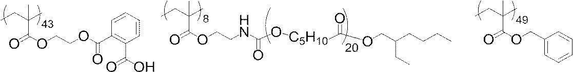

X1、X2、X3、X4、およびX5は、それぞれ独立に、水素原子又は炭素数1~12のアルキル基であることが好ましく、水素原子又はメチル基であることがより好ましく、メチル基がさらに好ましい。
Y1、Y2、Y3、およびY4は、それぞれ独立に、2価の連結基を表す。2価の連結基としては、-CO-、-O-、-NH-、アルキレン基、アリーレン基およびこれらの組み合わせからなる基が挙げられる。
Z1、Z2、Z3、およびZ4が表す1価の基の構造は、特に限定されない。例えば、アルキル基、ヒドロキシル基、アルコキシ基、アリールオキシ基、ヘテロアリールオキシ基、アルキルチオエーテル基、アリールチオエーテル基、ヘテロアリールチオエーテル基、およびアミノ基などが挙げられる。 W 1 , W 2 , W 3 , and W 4 are preferably oxygen atoms.
X 1 , X 2 , X 3 , X 4 , and X 5 are each independently preferably a hydrogen atom or an alkyl group having 1 to 12 carbon atoms, more preferably a hydrogen atom or a methyl group, More preferred is a methyl group.
Y 1 , Y 2 , Y 3 , and Y 4 each independently represent a divalent linking group. Examples of the divalent linking group include —CO—, —O—, —NH—, an alkylene group, an arylene group, and a group consisting of a combination thereof.
The structure of the monovalent group represented by Z 1 , Z 2 , Z 3 , and Z 4 is not particularly limited. Examples thereof include an alkyl group, a hydroxyl group, an alkoxy group, an aryloxy group, a heteroaryloxy group, an alkylthioether group, an arylthioether group, a heteroarylthioether group, and an amino group.
オリゴイミン系樹脂は、例えば、式(I-1)で表される繰り返し単位と、式(I-2)で表される繰り返し単位、および、式(I-2a)で表される繰り返し単位のうちの少なくともいずれかを含む樹脂などが挙げられる。 As the dispersant, an oligoimine resin containing a nitrogen atom in at least one of the main chain and the side chain can also be used. The oligoimine-based resin has a repeating unit having a group X having a partial structure having a functional group of pKa14 or less, and a side chain containing a side chain Y having 40 to 10,000 atoms, and has a main chain and a side chain A resin having a basic nitrogen atom in at least one of them is preferred. The basic nitrogen atom is not particularly limited as long as it is a basic nitrogen atom.
The oligoimine resin includes, for example, a repeating unit represented by the formula (I-1), a repeating unit represented by the formula (I-2), and a repeating unit represented by the formula (I-2a). And a resin containing at least one of the above.

R8およびR9はR1と同義の基である。
Lは単結合、アルキレン基(炭素数1~6が好ましい)、アルケニレン基(炭素数2~6が好ましい)、アリーレン基(炭素数6~24が好ましい)、ヘテロアリーレン基(炭素数1~6が好ましい)、イミノ基(炭素数0~6が好ましい)、エーテル基、チオエーテル基、カルボニル基、またはこれらの組合せに係る連結基である。なかでも、単結合または-CR5R6-NR7-(イミノ基がXもしくはYの方になる)であることが好ましい。ここで、R5およびR6は各々独立に、水素原子、ハロゲン原子、アルキル基(炭素数1~6が好ましい)を表す。R7は水素原子または炭素数1~6のアルキル基である。
Laは、CR8CR9とNとともに環構造形成する構造部位であり、CR8CR9の炭素原子と合わせて炭素数3~7の非芳香族複素環を形成する構造部位であることが好ましい。より好ましくは、CR8CR9の炭素原子およびN(窒素原子)を合わせて5~7員の非芳香族複素環を形成する構造部位であり、さらに好ましくは5員の非芳香族複素環を形成する構造部位であり、特に好ましくはピロリジンを形成する構造部位である。この構造部位はさらにアルキル基等の置換基を有していてもよい。
XはpKa14以下の官能基を有する部分構造を有する基を表す。
Yは原子数40~10,000の側鎖を表す。
上記樹脂(オリゴイミン系樹脂)は、さらに式(I-3)、式(I-4)、および、式(I-5)で表される繰り返し単位から選ばれる1種以上を共重合成分として含有していてもよい。上記樹脂が、このような繰り返し単位を含むことで、顔料の分散性能を更に向上させることができる。 R 1 and R 2 each independently represents a hydrogen atom, a halogen atom or an alkyl group (preferably having 1 to 6 carbon atoms). a independently represents an integer of 1 to 5; * Represents a connecting part between repeating units.
R 8 and R 9 are the same groups as R 1 .
L is a single bond, an alkylene group (preferably having 1 to 6 carbon atoms), an alkenylene group (preferably having 2 to 6 carbon atoms), an arylene group (preferably having 6 to 24 carbon atoms), a heteroarylene group (having 1 to 6 carbon atoms). Are preferred), an imino group (preferably having a carbon number of 0 to 6), an ether group, a thioether group, a carbonyl group, or a combination group thereof. Among these, a single bond or —CR 5 R 6 —NR 7 — (where the imino group is X or Y) is preferable. Here, R 5 and R 6 each independently represent a hydrogen atom, a halogen atom, or an alkyl group (preferably having 1 to 6 carbon atoms). R 7 is a hydrogen atom or an alkyl group having 1 to 6 carbon atoms.
L a is a structural site ring structure formed together with CR 8 CR 9 and N, be combined with the carbon atoms of CR 8 CR 9 is a structural site that form a non-aromatic heterocyclic ring having 3 to 7 carbon atoms preferable. More preferably, it is a structural part that forms a 5- to 7-membered non-aromatic heterocyclic ring by combining the carbon atom of CR 8 CR 9 and N (nitrogen atom), and more preferably a 5-membered non-aromatic heterocyclic ring. A structural site to be formed, particularly preferably a structural site to form pyrrolidine. This structural part may further have a substituent such as an alkyl group.
X represents a group having a partial structure having a functional group of pKa14 or less.
Y represents a side chain having 40 to 10,000 atoms.
The resin (oligoimine-based resin) further contains, as a copolymerization component, one or more selected from repeating units represented by formula (I-3), formula (I-4), and formula (I-5) You may do it. When the resin contains such a repeating unit, the dispersion performance of the pigment can be further improved.

Yaはアニオン基を有する原子数40~10,000の側鎖を表す。式(I-3)で表される繰り返し単位は、主鎖部に一級又は二級アミノ基を有する樹脂に、アミンと反応して塩を形成する基を有するオリゴマー又はポリマーを添加して反応させることで形成することが可能である。 R 1 , R 2 , R 8 , R 9 , L, La, a and * are as defined in the formulas (I-1), (I-2) and (I-2a).
Ya represents a side chain having an anionic group having 40 to 10,000 atoms. The repeating unit represented by the formula (I-3) is reacted by adding an oligomer or polymer having a group that reacts with an amine to form a salt to a resin having a primary or secondary amino group in the main chain. Can be formed.


本発明において、金属含有量の少ない溶剤を用いることが好ましく、溶剤の金属含有量は、例えば10ppb以下であることが好ましい。必要に応じてpptレベルの溶剤を用いてもよく、そのような高純度溶剤は、例えば、東洋合成社が提供している。
溶剤から金属等の不純物を除去する方法としては、例えば、蒸留(分子蒸留または薄膜蒸留等)、および、フィルターを用いた濾過を挙げることができる。フィルターを用いたろ過におけるフィルター孔径としては、ポアサイズ10nm以下が好ましく、5nm以下がより好ましく、3nm以下がさらに好ましい。フィルターとしては、ポリテトラフロロエチレン製、ポリエチレン製、または、ナイロン製のフィルターが好ましい。
溶剤は、異性体(同じ原子数で異なる構造の化合物)が含まれていてもよい。また、異性体は、1種のみが含まれていてもよいし、複数種含まれていてもよい。
溶剤の配合量は、組成物の固形分濃度が5~80質量%となる濃度が好ましい。 As the solvent, for example, reference can be made to the examples described in paragraphs 096 to 0499 of JP2012-208494A, the contents of which are incorporated herein. Only 1 type may be used for a solvent and it may use 2 or more types together.
In the present invention, it is preferable to use a solvent having a low metal content, and the metal content of the solvent is preferably 10 ppb or less, for example. A ppt level solvent may be used as necessary, and such a high-purity solvent is provided by Toyo Gosei Co., Ltd., for example.
Examples of the method for removing impurities such as metals from the solvent include distillation (molecular distillation or thin film distillation, etc.) and filtration using a filter. The filter pore size in filtration using a filter is preferably 10 nm or less, more preferably 5 nm or less, and even more preferably 3 nm or less. As the filter, a filter made of polytetrafluoroethylene, polyethylene, or nylon is preferable.
The solvent may contain isomers (compounds having the same number of atoms and different structures). Moreover, only 1 type may be included and the isomer may be included multiple types.
The amount of the solvent is preferably such that the solid content of the composition is 5 to 80% by mass.
アルカリ可溶性樹脂としては、下記一般式(ED)で示される化合物および/または下記一般式(ED2)で表される化合物(以下、これらの化合物を「エーテルダイマー」と称することもある。)を必須とする単量体成分を重合してなるポリマー(a)が好ましく挙げられる。 As examples of the alkali-soluble resin, reference can be made to the examples described in JP-A-2012-208494, paragraphs 0558 to 0572, the contents of which are incorporated herein.
As the alkali-soluble resin, a compound represented by the following general formula (ED) and / or a compound represented by the following general formula (ED2) (hereinafter, these compounds may be referred to as “ether dimers”) are essential. The polymer (a) obtained by polymerizing the monomer component is preferably mentioned.

一般式(ED2)

一般式(ED2)中、Rは、水素原子または炭素数1~30の有機基を表す。一般式(ED2)の具体例としては、特開2010-168539号公報の記載を参酌できる。
アルカリ可溶性樹脂は、1種のみ用いてもよいし、2種以上を併用してもよい。
アルカリ可溶性樹脂が赤外線透過組成物に含まれる場合、アルカリ可溶性樹脂の含有量は、赤外線透過組成物の固形分に対して、1~15質量%が好ましい。 In general formula (ED), R 1 and R 2 each independently represent a hydrogen atom or a hydrocarbon group having 1 to 25 carbon atoms which may have a substituent.
General formula (ED2)
In general formula (ED2), R represents a hydrogen atom or an organic group having 1 to 30 carbon atoms. As a specific example of the general formula (ED2), the description in JP 2010-168539 A can be referred to.
Only 1 type may be used for alkali-soluble resin, and it may use 2 or more types together.
When the alkali-soluble resin is contained in the infrared transmitting composition, the content of the alkali-soluble resin is preferably 1 to 15% by mass with respect to the solid content of the infrared transmitting composition.

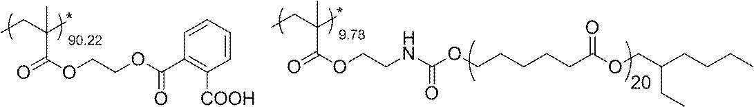

フッ素系界面活性剤としては、フッ素原子の官能基を持つ分子構造で、熱を加えると官能基の部分が切れてフッ素原子が揮発するアクリル系化合物も好適に使用できる。フッ素原子の官能基を持つ分子構造で、熱を加えると官能基の部分が切れてフッ素原子が揮発するアクリル系化合物としてはDIC社製のメガファックDSシリーズ(化学工業日報、2016年2月22日)(日経産業新聞、2016年2月23日)、例えばメガファックDS-21を用いてもよい。 The weight average molecular weight of the above compound is preferably 3,000 to 50,000, for example, 14,000. % Which shows the ratio of a repeating unit in said compound is the mass%.
As the fluorine-based surfactant, an acrylic compound that has a molecular structure having a functional group of fluorine atoms and the functional group portion is cut off when heat is applied and the fluorine atoms volatilize can be suitably used. DIC's MegaFuck DS series (Chemical Industry Daily, February 22, 2016) is an acrylic compound that has a molecular structure with a functional group of fluorine atoms and the functional group is cut off when heat is applied and the fluorine atoms volatilize. (Nikkei Sangyo Shimbun, February 23, 2016), for example, MegaFuck DS-21 may be used.
界面活性剤は、1種のみ用いてもよいし、2種以上を併用してもよい。
界面活性剤が赤外線透過組成物に含まれる場合、界面活性剤の含有量は、赤外線透過組成物の固形分に対して、0.001~2.0質量%が好ましい。 As examples of the surfactant, for example, the examples described in paragraphs 0549 to 0557 of JP2012-208494A can be referred to, and the contents thereof are incorporated in the present specification. In addition, as other examples of the surfactant, the examples described in paragraphs 0117 to 0132 of Japanese Patent No. 5809794 can be referred to, and the contents thereof are incorporated in the present specification.
Only one surfactant may be used, or two or more surfactants may be used in combination.
When the surfactant is contained in the infrared transmitting composition, the content of the surfactant is preferably 0.001 to 2.0% by mass with respect to the solid content of the infrared transmitting composition.

401N、X-40-9227、X-40-9247、KR-510、KR-9218、KR-213、X-40-2308、X-40-9238等が挙げられる。
また、アルコキシシリル基を有する化合物は、アルコキシシリル基を側鎖に有するポリマーを用いることもできる。
アルコキシシリル基を有する化合物が赤外線透過組成物に含まれる場合、アルコキシシリル基を有する化合物の含有量は、赤外線透過組成物の固形分に対して、0.1~30質量%が好ましい。 Commercially available products include Shin-Etsu Silicone's KBM-13, KBM-22, KBM-103, KBE-13, KBE-22, KBE-103, KBM-3033, KBE-3033, KBM-3063, KBM-3066, KBM-3086, KBE-3063, KBE-3083, KBM-3103, KBM-3066, KBM-7103, SZ-31, KPN-3504, KBM-1003, KBE-1003, KBM-303, KBM-402, KBM- 403, KBE-402, KBE-403, KBM-1403, KBM-502, KBM-503, KBE-502, KBE-503, KBM-5103, KBM-602, KBM-603, KBM-903, KBE-903, KBE-9103, KBM-573, KBM-575, K M-9659, KBE-585, KBM-802, KBM-803, KBE-846, KBE-9007, X-40-1053, X-41-1059A, X-41-1056, X-41-1805, X- 41-1818, X-41-1810, X-40-2651, X-40-2655A, KR-513, KC-89S, KR-500, X-40-9225, X-40-9246, X-40- 9250, KR-
401N, X-40-9227, X-40-9247, KR-510, KR-9218, KR-213, X-40-2308, X-40-9238 and the like.
Moreover, the compound which has an alkoxy silyl group in a side chain can also be used for the compound which has an alkoxy silyl group.
When the compound having an alkoxysilyl group is contained in the infrared transmitting composition, the content of the compound having an alkoxysilyl group is preferably 0.1 to 30% by mass with respect to the solid content of the infrared transmitting composition.
第2の実施の形態の赤外線透過組成物は、着色剤およびアルカリ可溶性樹脂を含み、着色剤中に、少なくとも赤色顔料と、一般式(A2)または一般式(A3)で表される青色顔料の少なくとも1種とを含み、全着色剤中、赤色顔料の含有量が20~50質量%、青色顔料の含有量が25~55質量%である。
赤外線透過組成物は、上記青色顔料および赤色顔料以外の他の着色剤を含むことが好ましい。また、赤外線透過組成物は、上記成分以外の他の成分をさらに含んでいてもよい。 (Second embodiment of infrared transmitting composition)
The infrared transmitting composition of the second embodiment includes a colorant and an alkali-soluble resin, and includes at least a red pigment and a blue pigment represented by the general formula (A2) or the general formula (A3) in the colorant. And the content of the red pigment is 20 to 50% by mass, and the content of the blue pigment is 25 to 55% by mass.
The infrared transmitting composition preferably contains a colorant other than the blue pigment and the red pigment. The infrared transmitting composition may further contain other components than the above components.
一般式(A2)

一般式(A2)中、X1~X4はそれぞれ独立して、置換基を表す。R0Aは、水素原子または1価の置換基を表す。m1~m4は、それぞれ独立して0~4の整数を表す。m1~m4が2以上のとき、X1~X4はそれぞれ同一でも異なっていてもよい。
一般式(A3)

一般式(A3)中、X5~X12はそれぞれ独立して、置換基を表す。R0Bは二価の置換基を表す。m5~m12は、それぞれ独立して0~4の整数を表す。m5~m12が2以上のとき、X5~X12はそれぞれ同一でも異なっていてもよい。 The blue pigment is a compound represented by general formula (A2) or general formula (A3).
General formula (A2)
In general formula (A2), X 1 to X 4 each independently represent a substituent. R 0A represents a hydrogen atom or a monovalent substituent. m1 to m4 each independently represents an integer of 0 to 4. When m1 to m4 are 2 or more, X 1 to X 4 may be the same or different.
General formula (A3)
In general formula (A3), X 5 to X 12 each independently represents a substituent. R 0B represents a divalent substituent. m5 to m12 each independently represents an integer of 0 to 4. When m5 to m12 are 2 or more, X 5 to X 12 may be the same or different.
特に、C.I.Pigment Red 254と、一般式(A4)で表される化合物であってC.I.Pigment Red 254ではない化合物を含むことが好ましい。 The red pigment preferably includes a symmetric red pigment and an asymmetric red pigment.
In particular, C.I. I. Pigment Red 254, a compound represented by the general formula (A4), and C.I. I. It is preferred to include a compound that is not Pigment Red 254.
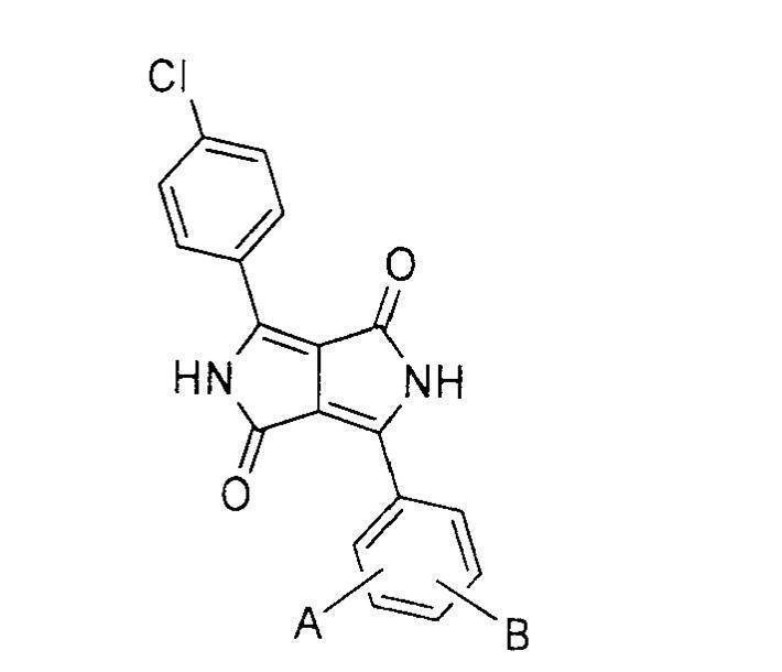
一般式(A4)中、AおよびBは、それぞれ独立して、水素原子、フッ素原子、塩素原子、臭素原子、炭素数1~4のアルキル基、炭素数1~4のアルコキシ基、シアノ基、-CF3、または、-CON(R1)R2を表す。R1およびR2は、それぞれ独立して、水素原子、炭素数1~20のアルキル基、または、フェニル基を表す。
赤色顔料として、対称構造の化合物と非対称構造の化合物とを含む場合、対称構造の化合物と非対称構造の化合物との質量比は、99:1~80:15が好ましく、98:2~90:10がより好ましい。 General formula (A4)
In general formula (A4), A and B are each independently a hydrogen atom, a fluorine atom, a chlorine atom, a bromine atom, an alkyl group having 1 to 4 carbon atoms, an alkoxy group having 1 to 4 carbon atoms, a cyano group, —CF 3 or —CON (R 1 ) R 2 is represented. R 1 and R 2 each independently represents a hydrogen atom, an alkyl group having 1 to 20 carbon atoms, or a phenyl group.
When the red pigment includes a compound having a symmetric structure and a compound having an asymmetric structure, the mass ratio of the compound having a symmetric structure and the compound having an asymmetric structure is preferably 99: 1 to 80:15, and 98: 2 to 90:10. Is more preferable.
赤外線透過組成物の全着色剤中、赤色顔料および上記青色顔料以外の着色剤の含有量の合計は、5~45質量%が好ましく、15~35質量%がより好ましい。 As the other colorant, the other colorant of the first embodiment described above can be used.
The total content of the red pigment and the colorant other than the blue pigment in the total colorant of the infrared transmitting composition is preferably 5 to 45% by mass, more preferably 15 to 35% by mass.
上記以外の他の成分としては、第1の実施の形態で説明した、重合性化合物、重合開始剤、顔料分散剤、顔料誘導体、溶剤、界面活性剤、および、アルコキシシリル基を有する化合物等を用いることができる。これらの好ましい範囲も第一の実施の形態と同様である。 As the alkali-soluble resin, the alkali-soluble resin described in the first embodiment can be used, and the preferable range is also the same.
As other components other than those described above, the polymerizable compound, polymerization initiator, pigment dispersant, pigment derivative, solvent, surfactant, compound having an alkoxysilyl group, and the like described in the first embodiment are used. Can be used. These preferable ranges are also the same as those in the first embodiment.
第3の実施の形態の赤外線透過組成物は、着色剤と樹脂とを含み、波長400~830nmの範囲における吸光度の最小値Aと、波長1000~1300nmの範囲における吸光度の最大値Bとの比であるA/Bが、4.5以上である。
上記吸光度の条件は、どのような手段によって達成されてもよいが、例えば、赤外線透過組成物に、波長800~900nmの範囲に吸収極大を有する第1の着色剤を1種類以上と、波長400~700nmの範囲に吸収極大を有する第2の着色剤を2種類以上含有させるとともに、各着色剤の種類および含有量を調整することにより、上記吸光度の条件を好適に達成できる。
赤外線透過組成物は、第1の着色剤および第2の着色剤以外の着色剤(第3の着色剤)を含んでいてもよい。
また、赤外線透過組成物は、着色剤および樹脂以外の他の成分をさらに含んでいてもよい。 (Third embodiment of infrared transmitting composition)
The infrared transmitting composition of the third embodiment includes a colorant and a resin, and is a ratio between the minimum absorbance A in the wavelength range of 400 to 830 nm and the maximum absorbance B in the wavelength range of 1000 to 1300 nm. A / B is 4.5 or more.
The absorbance condition may be achieved by any means. For example, in the infrared transmitting composition, at least one first colorant having an absorption maximum in the wavelength range of 800 to 900 nm and a wavelength of 400 are used. By incorporating two or more types of second colorants having an absorption maximum in the range of ˜700 nm and adjusting the type and content of each colorant, the above-described absorbance conditions can be suitably achieved.
The infrared transmitting composition may contain a colorant (third colorant) other than the first colorant and the second colorant.
The infrared transmitting composition may further contain other components other than the colorant and the resin.
ジケトピロロピロール色素化合物は、顔料でも染料でもよいが、耐熱性に優れた膜を形成できる赤外線透過組成物が得られやすいという理由から顔料が好ましい。ジケトピロロピロール色素化合物は、下記一般式(A5)で表される化合物が好ましい。 Examples of the first colorant include diketopyrrolopyrrole dye compounds, copper compounds, cyanine dye compounds, phthalocyanine compounds, imonium compounds, thiol complex compounds, transition metal oxide compounds, squarylium dye compounds, Examples include naphthalocyanine dye compounds, quatarylene dye compounds, dithiol metal complex dye compounds, and croconium compounds.
The diketopyrrolopyrrole coloring compound may be a pigment or a dye, but a pigment is preferred because an infrared transmitting composition capable of forming a film having excellent heat resistance can be easily obtained. The diketopyrrolopyrrole dye compound is preferably a compound represented by the following general formula (A5).

一般式(A5)中、R1aおよびR1bは、それぞれ独立にアルキル基、アリール基、または、ヘテロアリール基を表し、R2およびR3は、それぞれ独立に水素原子または置換基を表し、R2およびR3の少なくとも一方は電子吸引性基であり、R2およびR3は互いに結合して環を形成してもよく、R4は、水素原子、アルキル基、アリール基、ヘテロアリール基、置換ホウ素、または、金属原子を表し、R4は、R1a、R1bおよびR3から選ばれる1以上と共有結合または配位結合してもよい。
一般式(A5)で表される化合物は、例えば、特開2009-263614号公報の段落0016~0058の記載の例を参酌でき、この内容は本願明細書に組み込まれる。
赤外線透過組成物において、第1の着色剤の含有量は、赤外線透過組成物の全固形分に対して、0~60質量%であることが好ましく、10~40質量%であることがより好ましい。
赤外線透過組成物において、第1の着色剤は、1種単独で用いてもよく、2種以上併用してもよい。2種以上併用する場合は、合計が上記範囲であることが好ましい。 General formula (A5)
In General Formula (A5), R 1a and R 1b each independently represent an alkyl group, an aryl group, or a heteroaryl group, R 2 and R 3 each independently represent a hydrogen atom or a substituent, and R At least one of 2 and R 3 is an electron-withdrawing group, R 2 and R 3 may be bonded to each other to form a ring, and R 4 is a hydrogen atom, an alkyl group, an aryl group, a heteroaryl group, It represents a substituted boron or a metal atom, and R 4 may be covalently or coordinated with one or more selected from R 1a , R 1b and R 3 .
For the compound represented by the general formula (A5), for example, the examples described in paragraphs 0016 to 0058 of JP-A-2009-263614 can be referred to, and the contents thereof are incorporated in the present specification.
In the infrared transmitting composition, the content of the first colorant is preferably 0 to 60% by mass, and more preferably 10 to 40% by mass with respect to the total solid content of the infrared transmitting composition. .
In the infrared transmitting composition, the first colorant may be used alone or in combination of two or more. When using 2 or more types together, it is preferable that the sum total is the said range.
第2の着色剤が、赤色着色剤と、黄色着色剤と、青色着色剤と、紫色着色剤とを組み合わせてなる場合、赤色着色剤の、第2の着色剤全量に対する質量比が0.1~0.4であり、黄色着色剤の、第2の着色剤全量に対する質量比が0.1~0.4であり、青色着色剤の、第2の着色剤全量に対する質量比が0.20~0.60であり、紫色着色剤の、第2の着色剤全量に対する質量比が0.01~0.30であることが好ましい。
第2の着色剤の含有量は、赤外線透過組成物の全固形分の10~60質量%であることが好ましく、30~50質量%であることがより好ましい。
赤外線透過組成物において、第1の着色剤と第2の着色剤の合計量は、赤外線透過組成物の全固形分に対して、1~80質量%であることが好ましく、20~70質量%であることがより好ましく、30~70質量%であることがさらに好ましい。 The second colorant may be a pigment or a dye, but is preferably a pigment. The second colorant preferably contains two or more colorants selected from a red colorant, a yellow colorant, a blue colorant, and a purple colorant. As the second colorant, the other colorant described in the first embodiment can be used.
When the second colorant is a combination of a red colorant, a yellow colorant, a blue colorant, and a purple colorant, the mass ratio of the red colorant to the total amount of the second colorant is 0.1. The mass ratio of the yellow colorant to the total amount of the second colorant is 0.1 to 0.4, and the mass ratio of the blue colorant to the total amount of the second colorant is 0.20. It is preferable that the mass ratio of the purple colorant to the total amount of the second colorant is 0.01 to 0.30.
The content of the second colorant is preferably 10 to 60% by mass, and more preferably 30 to 50% by mass, based on the total solid content of the infrared transmitting composition.
In the infrared transmitting composition, the total amount of the first coloring agent and the second coloring agent is preferably 1 to 80% by mass, and 20 to 70% by mass with respect to the total solid content of the infrared transmitting composition. More preferably, it is more preferably 30 to 70% by mass.
他の成分としては、第1の実施の形態で説明した、重合性化合物、重合開始剤、顔料誘導体、溶剤、界面活性剤、および、アルコキシシリル基を有する化合物等を用いることができる。これらの好ましい範囲も第一の実施の形態と同様である。 Examples of the resin contained in the infrared transmitting composition include pigment dispersants and alkali-soluble resins. As the pigment dispersant and the alkali-soluble resin, the pigment dispersant and the alkali-soluble resin described in the first embodiment can be used.
As other components, the polymerizable compound, the polymerization initiator, the pigment derivative, the solvent, the surfactant, the compound having an alkoxysilyl group, and the like described in the first embodiment can be used. These preferable ranges are also the same as those in the first embodiment.
第4の実施の形態の赤外線透過組成物は、着色剤と重合性化合物とを含み、重合性化合物が、アルキレンオキシ基を繰り返し単位として2以上含む鎖(以下、アルキレンオキシ鎖ともいう)を有する重合性化合物を含み、赤外線透過組成物の、波長400nm以上580nm未満の範囲における吸光度の最小値Aと、波長580nm以上770nm以下の範囲における吸光度の最小値Bとの比率A/Bが0.3~3であり、波長400nm以上750nm以下の範囲における吸光度の最小値Cと、波長850nm以上1300nm以下の範囲における吸光度の最大値Dとの比率C/Dが5以上である。
赤外線透過組成物は、着色剤および重合性化合物以外の他の成分をさらに含んでいてもよい。 (Fourth embodiment of infrared transmitting composition)
The infrared transmitting composition of the fourth embodiment includes a colorant and a polymerizable compound, and the polymerizable compound has a chain including two or more alkyleneoxy groups as repeating units (hereinafter also referred to as an alkyleneoxy chain). The ratio A / B between the minimum absorbance A in the wavelength range of 400 nm to less than 580 nm and the minimum absorbance B in the wavelength range of 580 nm to 770 nm of the infrared transmitting composition containing the polymerizable compound is 0.3. The ratio C / D of the minimum absorbance C in the wavelength range from 400 nm to 750 nm and the maximum absorbance D in the wavelength range from 850 nm to 1300 nm is 5 or more.
The infrared transmitting composition may further contain other components other than the colorant and the polymerizable compound.
一般式(A7)

General formula (A7)
一般式(A8)
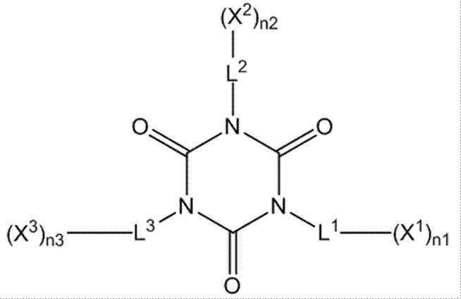
一般式(A8)において、X1~X3は、それぞれ独立に水素原子または重合性基を表し、X1~X3の少なくとも一つは、重合性基を表す。
L1は(1+n1)価の連結基を表し、L2は(1+n2)価を表し、L3は(1+n3)価を表し、L1~L3の少なくとも1つは-((CH2)a-O)b-を含む連結基を表す。aは2以上の整数を表し、bは2以上の整数を表す。一般式(A8)において、n1~n3は、それぞれ独立に、1以上の整数を表し、1または2が好ましい。
L1~L3の少なくとも1つが有する-((CH2)a-O)b-を含む連結基は、好ましくはエチレンオキシ基、プロピレンオキシ基であることが好ましい。
アルキレンオキシ鎖を有する重合性化合物としては、第1の実施の形態で説明した重合性化合物を用いることもできる。 As a polymeric compound which has a partial structure represented by general formula (A7), the polymeric compound represented by the following general formula (A8) is mentioned, for example.
General formula (A8)
In the general formula (A8), X 1 to X 3 each independently represents a hydrogen atom or a polymerizable group, and at least one of X 1 to X 3 represents a polymerizable group.
L 1 represents a (1 + n1) valent linking group, L 2 represents a (1 + n2) valence, L 3 represents a (1 + n3) valence, and at least one of L 1 to L 3 represents — ((CH 2 ) a -O) represents a linking group containing b- . a represents an integer of 2 or more, and b represents an integer of 2 or more. In the general formula (A8), n1 to n3 each independently represents an integer of 1 or more, preferably 1 or 2.
The linking group containing — ((CH 2 ) a —O) b — possessed by at least one of L 1 to L 3 is preferably an ethyleneoxy group or a propyleneoxy group.
As the polymerizable compound having an alkyleneoxy chain, the polymerizable compound described in the first embodiment can also be used.
第5の実施の形態の赤外線透過組成物は、着色剤と重合性化合物とを含み、重合性化合物は、アルキレンオキシ基を繰り返し単位として2以上含む鎖を有する重合性化合物を含み、着色剤は、赤色着色剤および紫色着色剤から選ばれる1種以上の着色剤Aと、黄色着色剤と、青色着色剤と、を少なくとも含み、赤色着色剤および紫色着色剤から選ばれる着色剤Aの着色剤全量に対する質量比である着色剤A/全着色剤が、0.01~0.7であり、黄色着色剤の着色剤全量に対する質量比である黄色着色剤/全着色剤が0.05~0.5であり、青色着色剤の着色剤全量に対する質量比である青色着色剤/全着色剤が0.05~0.6である。
赤外線透過組成物は、着色剤および重合性化合物以外の他の成分をさらに含んでいてもよい。 (Fifth embodiment of infrared transmitting composition)
The infrared transmitting composition of the fifth embodiment includes a colorant and a polymerizable compound, the polymerizable compound includes a polymerizable compound having a chain containing two or more alkyleneoxy groups as repeating units, and the colorant is One or more colorants A selected from a red colorant and a purple colorant, a yellow colorant, and a blue colorant, and a colorant A of a colorant A selected from a red colorant and a purple colorant Colorant A / total colorant, which is a mass ratio to the total amount, is 0.01 to 0.7, and yellow colorant / total colorant, which is a mass ratio of the yellow colorant to the total amount of colorant, is 0.05 to 0. The blue colorant / total colorant, which is a mass ratio of the blue colorant to the total amount of the colorant, is 0.05 to 0.6.
The infrared transmitting composition may further contain other components other than the colorant and the polymerizable compound.
重合性化合物は、第4の実施の形態で説明したアルキレンオキシ鎖を有する重合性化合物と同義である。
他の成分としては、第1の実施の形態で説明した、重合開始剤、顔料分散剤、顔料誘導体、溶剤、アルカリ可溶性樹脂、界面活性剤、および、アルコキシシリル基を有する化合物等を用いることができる。これらの好ましい範囲も第一の実施の形態と同様である。 The colorant is synonymous with the other colorant of the first embodiment described above.
The polymerizable compound is synonymous with the polymerizable compound having an alkyleneoxy chain described in the fourth embodiment.
As other components, the polymerization initiator, the pigment dispersant, the pigment derivative, the solvent, the alkali-soluble resin, the surfactant, and the compound having an alkoxysilyl group described in the first embodiment may be used. it can. These preferable ranges are also the same as those in the first embodiment.
第6の実施の形態の赤外線透過組成物は、着色剤と重合性化合物とを含み、着色剤の質量Pと重合性化合物の質量Mとの比率P/Mが、0.05~0.35であり、赤外線透過組成物の全固形分中における重合性化合物の含有量が25~65質量%であり、赤外線透過組成物の、波長400nm以上580nm未満の範囲における吸光度の最小値Aと、波長580nm以上770nm以下の範囲における吸光度の最小値Bとの比率A/Bが0.3~3であり、波長400nm以上750nm以下の範囲における吸光度の最小値Cと、波長850nm以上1300nm以下の範囲における吸光度の最大値Dとの比率C/Dが5以上である。
赤外線透過組成物は、着色剤および重合性化合物以外の他の成分をさらに含んでいてもよい。 (Sixth embodiment of infrared transmitting composition)
The infrared transmitting composition according to the sixth embodiment includes a colorant and a polymerizable compound, and a ratio P / M between the mass P of the colorant and the mass M of the polymerizable compound is 0.05 to 0.35. The content of the polymerizable compound in the total solid content of the infrared transmitting composition is 25 to 65% by mass, and the minimum value A of the absorbance of the infrared transmitting composition in the wavelength range of 400 nm to less than 580 nm, and the wavelength The ratio A / B to the minimum absorbance B in the range of 580 nm to 770 nm is 0.3 to 3, the minimum absorbance C in the wavelength range of 400 nm to 750 nm, and the wavelength range of 850 nm to 1300 nm. The ratio C / D with respect to the maximum absorbance D is 5 or more.
The infrared transmitting composition may further contain other components other than the colorant and the polymerizable compound.
他の成分としては、第1の実施の形態で説明した、重合開始剤、顔料分散剤、顔料誘導体、溶剤、アルカリ可溶性樹脂、界面活性剤、および、アルコキシシリル基を有する化合物等を用いることができる。これらの好ましい範囲も第一の実施の形態と同様である。 The colorant and the polymerizable compound are respectively synonymous with the other colorant and the polymerizable compound in the first embodiment described above.
As other components, the polymerization initiator, the pigment dispersant, the pigment derivative, the solvent, the alkali-soluble resin, the surfactant, and the compound having an alkoxysilyl group described in the first embodiment may be used. it can. These preferable ranges are also the same as those in the first embodiment.
第7の実施の形態の赤外線透過組成物は、着色剤と重合性化合物とを含み、着色剤の質量Pと重合性化合物の質量Mとの比率P/Mが、0.05~0.35であり、赤外線透過組成物の全固形分中における重合性化合物の含有量が25~65質量%であり、着色剤は、黄色着色剤と青色着色剤とを少なくとも含み、黄色着色剤の着色剤全量に対する質量比である黄色着色剤/全着色剤が0.1~0.5であり、青色着色剤の着色剤全量に対する質量比である青色着色剤/全着色剤が0.1~0.6である。
赤外線透過組成物は、着色剤および重合性化合物以外の他の成分をさらに含んでいてもよい。 (Seventh embodiment of infrared transmitting composition)
The infrared transmitting composition according to the seventh embodiment includes a colorant and a polymerizable compound, and a ratio P / M between the mass P of the colorant and the mass M of the polymerizable compound is 0.05 to 0.35. The content of the polymerizable compound in the total solid content of the infrared transmitting composition is 25 to 65% by mass, and the colorant includes at least a yellow colorant and a blue colorant, and a colorant for the yellow colorant The yellow colorant / total colorant, which is a mass ratio to the total amount, is 0.1 to 0.5, and the blue colorant / total colorant, which is a mass ratio of the blue colorant to the total amount of colorant, is 0.1 to 0.00. 6.
The infrared transmitting composition may further contain other components other than the colorant and the polymerizable compound.
他の成分としては、第1の実施の形態で説明した、重合開始剤、顔料分散剤、顔料誘導体、溶剤、アルカリ可溶性樹脂、界面活性剤、および、アルコキシシリル基を有する化合物等を用いることができる。これらの好ましい範囲も第一の実施の形態と同様である。 The colorant and the polymerizable compound are respectively synonymous with the other colorant and the polymerizable compound in the first embodiment described above.
As other components, the polymerization initiator, the pigment dispersant, the pigment derivative, the solvent, the alkali-soluble resin, the surfactant, and the compound having an alkoxysilyl group described in the first embodiment may be used. it can. These preferable ranges are also the same as those in the first embodiment.
第8の実施の形態の赤外線透過組成物は、膜厚1μmの膜を形成した際に、膜の厚み方向の光透過率の、波長400~750nmの範囲における最大値が20%以下であり、膜の厚み方向の光透過率の、波長900~1300nmの範囲における最小値が90%以上となる組成物である。
膜の分光特性、膜厚等の測定方法を以下に示す。
組成物をガラス基板上にスピンコート等の方法により、乾燥後の膜厚が1μmとなるように組成物を塗布し、膜を設け、得られた膜を100℃にて120秒間ホットプレートで乾燥する。
膜の膜厚は、膜を有する乾燥後の基板を、触針式表面形状測定器(ULVAC社製 DEKTAK150)を用いて測定する。
この膜を有する乾燥後の基板を、紫外可視近赤外分光光度計(日立ハイテクノロジーズ社製 U-4100)の分光光度計(ref.ガラス基板)を用いて、波長300~1300nmの範囲において透過率を測定する。
光透過率の条件は、どのような手段によって達成されてもよいが、例えば、組成物に顔料を2種以上含ませるとともに、各顔料の種類および含有量を調整することにより、上記光透過率の条件を好適に達成できる。
赤外線透過組成物は、着色剤および着色剤以外の他の成分をさらに含んでいてもよい。
着色剤は、上述した第1の実施の形態の他の着色剤と同義である。
他の成分としては、第1の実施の形態で説明した、重合性化合物、重合開始剤、顔料分散剤、顔料誘導体、溶剤、アルカリ可溶性樹脂、界面活性剤、および、アルコキシシリル基を有する化合物等を用いることができる。これらの好ましい範囲も第一の実施の形態と同様である。 (Eighth embodiment of infrared transmitting composition)
In the infrared transmitting composition of the eighth embodiment, when a film having a thickness of 1 μm is formed, the maximum value of the light transmittance in the thickness direction of the film in the wavelength range of 400 to 750 nm is 20% or less, The composition is such that the minimum value of the light transmittance in the thickness direction of the film is 90% or more in the wavelength range of 900 to 1300 nm.
Measuring methods for the spectral characteristics and film thickness of the film are shown below.
The composition is applied onto a glass substrate by a method such as spin coating so that the film thickness after drying becomes 1 μm, a film is provided, and the obtained film is dried on a hot plate at 100 ° C. for 120 seconds. To do.
The film thickness of the film is measured using a stylus type surface shape measuring instrument (DEKTAK150 manufactured by ULVAC) for the dried substrate having the film.
The dried substrate having this film was transmitted in a wavelength range of 300 to 1300 nm using a spectrophotometer (ref. Glass substrate) of an ultraviolet-visible near-infrared spectrophotometer (U-4100 manufactured by Hitachi High-Technologies Corporation). Measure the rate.
The light transmittance condition may be achieved by any means. For example, the light transmittance can be achieved by adding two or more pigments to the composition and adjusting the type and content of each pigment. This condition can be suitably achieved.
The infrared transmitting composition may further contain a colorant and other components other than the colorant.
The colorant is synonymous with the other colorant of the first embodiment described above.
As other components, the polymerizable compound, the polymerization initiator, the pigment dispersant, the pigment derivative, the solvent, the alkali-soluble resin, the surfactant, and the compound having an alkoxysilyl group described in the first embodiment, etc. Can be used. These preferable ranges are also the same as those in the first embodiment.
第9の実施の形態の赤外線透過組成物は、顔料、光重合開始剤、および重合性化合物を含み、波長600nmにおける分光透過率が30%である赤外線透過層を形成した場合に、赤外線透過層が、下記(1)~(5)の条件を満足する組成物である。
(1)400nmにおける分光透過率が20%以下である。
(2)550nmにおける分光透過率が10%以下である。
(3)700nmにおける分光透過率が70%以上である。
(4)分光透過率50%を示す波長が、650nm~680nmの範囲である。
(5)赤外線透過層が0.55μm~1.8μmの範囲の膜厚を有する。
赤外線透過組成物の詳細は、例えば、特開2013-077009号公報の段落0020~0230の記載の例を参酌でき、この内容は本願明細書に組み込まれる。 (Ninth embodiment of infrared transmitting composition)
The infrared transmitting composition of the ninth embodiment includes a pigment, a photopolymerization initiator, and a polymerizable compound, and when an infrared transmitting layer having a spectral transmittance of 30% at a wavelength of 600 nm is formed, the infrared transmitting layer However, the composition satisfies the following conditions (1) to (5).
(1) The spectral transmittance at 400 nm is 20% or less.
(2) The spectral transmittance at 550 nm is 10% or less.
(3) The spectral transmittance at 700 nm is 70% or more.
(4) The wavelength showing a spectral transmittance of 50% is in the range of 650 nm to 680 nm.
(5) The infrared transmitting layer has a thickness in the range of 0.55 μm to 1.8 μm.
For details of the infrared transmitting composition, for example, reference can be made to the examples described in paragraphs 0020 to 0230 of JP2013-077009A, the contents of which are incorporated herein.
積層体は、上述した多層反射膜および光吸収層以外の他の層を含んでいてもよい。
積層体は、例えば、基板、易接着層、ハードコート層、紫外線吸収層、粘着層、および、表面保護層のうち少なくとも1つをさらに有することが好ましい。
以下、上記他の層について詳述する。 <Other layers>
The laminate may include other layers other than the multilayer reflective film and the light absorption layer described above.
The laminate preferably further includes at least one of, for example, a substrate, an easy adhesion layer, a hard coat layer, an ultraviolet absorption layer, an adhesive layer, and a surface protective layer.
Hereinafter, the other layers will be described in detail.
積層体は、基板を有していてもよい。
基板の種類は特に制限されず、公知の基板(好ましくは、透明基板)を使用することができる。例えば、ガラス基板、樹脂基板を好適に使用することができる。 (substrate)
The laminated body may have a substrate.
The kind in particular of board | substrate is not restrict | limited, A well-known board | substrate (preferably transparent substrate) can be used. For example, a glass substrate or a resin substrate can be preferably used.
積層体は、一方または両方の最外層として、易接着層を有していてもよい。易接着層は、例えば、積層体と合わせガラス用中間膜との接着性を改善する機能を有する。より具体的には、易接着層は、光反射層および/または基板と、合わせガラス用中間膜との接着性を改善する機能を有する。
易接着層の形成に利用可能な材料としては、ポリビニルブチラール(PVB)樹脂が挙げられる。ポリビニルブチラール樹脂は、ポリビニルアルコール(PVA)とブチルアルデヒドとを酸触媒で反応させて生成するポリビニルアセタールの一種であり、下記構造の繰り返し単位を有する樹脂である。 (Easily adhesive layer)
The laminated body may have an easily bonding layer as one or both outermost layers. The easy-adhesion layer has a function of improving the adhesion between the laminate and the interlayer film for laminated glass, for example. More specifically, the easy-adhesion layer has a function of improving the adhesion between the light reflection layer and / or the substrate and the interlayer film for laminated glass.
Examples of a material that can be used for forming the easy-adhesion layer include polyvinyl butyral (PVB) resin. The polyvinyl butyral resin is a kind of polyvinyl acetal produced by reacting polyvinyl alcohol (PVA) and butyraldehyde with an acid catalyst, and is a resin having a repeating unit having the following structure.
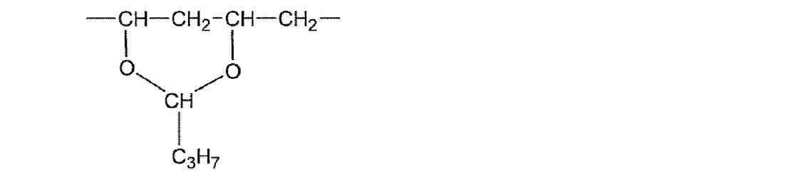
塗布方法としては、公知の種々の方法を利用することができる。乾燥時の温度は、塗布液の調製に用いた材料によって好ましい範囲が異なるが、一般的には、140~160℃程度が好ましい。乾燥時間についても特に制限はないが、一般的には、5~10分程度である。 The easy adhesion layer is preferably formed by coating. For example, it may be formed by coating on the surface of the light reflecting layer and / or the back surface of the substrate (the surface on which the light reflecting layer is not formed). More specifically, one type of polyvinyl butyral resin is dissolved in an organic solvent to prepare a coating solution. It can dry and can form an easily bonding layer. Examples of the solvent used for preparing the coating solution include methoxypropyl acetate (PGMEA), methyl ethyl ketone (MEK), and isopropanol (IPA).
As a coating method, various known methods can be used. The preferred drying temperature varies depending on the material used for the preparation of the coating solution, but is generally preferably about 140 to 160 ° C. The drying time is not particularly limited, but is generally about 5 to 10 minutes.
なお、易接着層の厚みは、0.1~2.0μmが好ましい。 Further, the easy-adhesion layer may be a layer made of an acrylic resin, a styrene / acrylic resin, a urethane resin, a polyester resin, or the like, so-called an undercoat layer. An easy adhesion layer made of these materials can also be formed by coating. Some commercially available polymer films are provided with an undercoat layer. Therefore, these commercially available products can be used as a substrate.
The thickness of the easy adhesion layer is preferably 0.1 to 2.0 μm.
積層体は、光反射層と基板との間に下塗り層を有していてもよい。光反射層と基板との密着力が弱いと、光反射層を積層して製造する際の工程で剥離故障が起きる場合、および、合わせガラスにした際の強度(耐衝撃性)低下を引き起こす場合がある。よって、下塗り層として、光反射層と基板との接着性を向上させることができる層を用いることができる。一方で、積層体から基板または基板と下塗り層とを剥離して、得られた光反射層と中間膜シート等の部材とを一体化する場合は、基板と下塗り層、または、下塗り層と光反射層との界面には、剥離可能な程度の接着性の弱さが必要である。この場合、後工程の点を考慮すると、下塗り層と基板との界面で剥離する方が好ましい。
下塗り層の材料としては、例えば、アクリル酸エステル共重合体、ポリ塩化ビニリデン、スチレンブタジエンゴム(SBR)、および、水性ポリエステル等が挙げられる。また、下塗り層の表面を中間膜と接着する態様では、下塗り層と中間膜との接着性が良好であるのが好ましい。その観点では、下塗り層は、上記材料とともに、ポリビニルブチラール樹脂も含むことが好ましい。
また、下塗り層は、上記したように密着力を適度に調節する必要があるので、グルタルアルデヒド、2、3-ジヒドロキシ-1、4-ジオキサン等のジアルデヒド類またはホウ酸等の硬膜剤を適宜用いて硬膜させることが好ましい。硬膜剤の添加量は、下塗り層の乾燥質量に対して、0.2~3.0質量%が好ましい。
下塗り層の厚みは、0.05~0.5μmが好ましい。 (Undercoat layer)
The laminate may have an undercoat layer between the light reflecting layer and the substrate. When the adhesion between the light reflecting layer and the substrate is weak, a peeling failure occurs in the process of stacking and manufacturing the light reflecting layer, and when the strength (impact resistance) of the laminated glass is reduced. There is. Therefore, a layer that can improve the adhesion between the light reflecting layer and the substrate can be used as the undercoat layer. On the other hand, when the substrate or the substrate and the undercoat layer are peeled from the laminate and the obtained light reflecting layer and the member such as the intermediate film sheet are integrated, the substrate and the undercoat layer, or the undercoat layer and the light are integrated. At the interface with the reflective layer, it is necessary that the adhesiveness is weak enough to be peeled off. In this case, it is preferable to peel at the interface between the undercoat layer and the substrate in consideration of the post-process point.
Examples of the material for the undercoat layer include acrylic acid ester copolymers, polyvinylidene chloride, styrene butadiene rubber (SBR), and aqueous polyester. Moreover, in the aspect which adhere | attaches the surface of undercoat with an intermediate film, it is preferable that the adhesiveness of an undercoat and an intermediate film is favorable. From that viewpoint, the undercoat layer preferably contains a polyvinyl butyral resin together with the above material.
In addition, since the undercoat layer needs to adjust the adhesive force appropriately as described above, dialdehydes such as glutaraldehyde, 2,3-dihydroxy-1,4-dioxane, or hardeners such as boric acid are used. It is preferable to use the film appropriately. The addition amount of the hardener is preferably 0.2 to 3.0% by mass relative to the dry mass of the undercoat layer.
The thickness of the undercoat layer is preferably 0.05 to 0.5 μm.
積層体は、光反射層と基板との間に配向層を有していてもよい。配向層は、光反射層中の液晶化合物の配向方向をより精密に規定する機能を有する。配向層は、有機化合物(好ましくはポリマー)のラビング処理、無機化合物の斜方蒸着、および、マイクログルーブを有する層の形成等の手段で設けることができる。さらには、電場の付与、磁場の付与、または、光照射により配向機能が生じる配向層も知られている。配向層は、光照射により配向が生じるものが好ましく、公知のものを好適に用いることができる。
配向層は、光反射層と隣接することが好ましいので、光反射層と基板または下塗り層との間に設けるのが好ましい。但し、下塗り層が配向層の機能を有していてもよい。
配向層は、隣接する、光反射層および下塗り層(または基板)のいずれに対しても、ある程度の密着力を有することが好ましい。 (Orientation layer)
The laminate may have an alignment layer between the light reflecting layer and the substrate. The alignment layer has a function of more precisely defining the alignment direction of the liquid crystal compound in the light reflection layer. The alignment layer can be provided by means such as a rubbing treatment of an organic compound (preferably a polymer), oblique vapor deposition of an inorganic compound, and formation of a layer having a microgroove. Furthermore, an alignment layer in which an alignment function is generated by application of an electric field, application of a magnetic field, or light irradiation is also known. The alignment layer is preferably one that undergoes alignment by light irradiation, and a known one can be suitably used.
Since the alignment layer is preferably adjacent to the light reflecting layer, it is preferably provided between the light reflecting layer and the substrate or the undercoat layer. However, the undercoat layer may have a function of an alignment layer.
The alignment layer preferably has a certain degree of adhesion to both the adjacent light reflection layer and undercoat layer (or substrate).
ポリマーの例としては、ポリメチルメタクリレ-ト、アクリル酸/メタクリル酸共重合体、スチレン/マレインイミド共重合体、ポリビニルアルコ-ルおよび変性ポリビニルアルコ-ル、ポリ(N-メチロ-ルアクリルアミド)、スチレン/ビニルトルエン共重合体、クロロスルホン化ポリエチレン、ニトロセルロース、ポリ塩化ビニル、塩素化ポリオレフィン、ポリエステル、ポリイミド、酢酸ビニル/塩化ビニル共重合体、エチレン/酢酸ビニル共重合体、カルボキシメチルセルロ-ス、ゼラチン、ポリエチレン、ポリプロピレン、および、ポリカーボネート等が挙げられる。ポリマーとしては、ポリ(N-メチロ-ルアクリルアミド)、カルボキシメチルセルロ-ス、ゼラチン、ポリビルアルコールおよび変性ポリビニルアルコール等の水溶性ポリマーが好ましく、ゼラチン、ポリビルアルコール、または、変性ポリビニルアルコールがより好ましく、ポリビルアルコール、または、変性ポリビニルアルコールがさらに好ましい。
また、配向層の表面を中間膜と接着する態様では、配向層と中間膜との接着性が良好であるのが好ましい。その観点では、配向層は、上記材料とともに、ポリビニルブチラール樹脂も含むことが好ましい。
上記配向層の厚みは、0.1~2.0μmが好ましい。 As a material used for the alignment layer, a polymer is preferable, and a polymer that can be crosslinked by itself or a polymer that is crosslinked by a crosslinking agent is often used. Of course, polymers having both functions are also used.
Examples of polymers include polymethyl methacrylate, acrylic acid / methacrylic acid copolymer, styrene / maleimide copolymer, polyvinyl alcohol and modified polyvinyl alcohol, poly (N-methylol acrylamide) Styrene / vinyl toluene copolymer, chlorosulfonated polyethylene, nitrocellulose, polyvinyl chloride, chlorinated polyolefin, polyester, polyimide, vinyl acetate / vinyl chloride copolymer, ethylene / vinyl acetate copolymer, carboxymethyl cellulose And gelatin, polyethylene, polypropylene, polycarbonate and the like. The polymer is preferably a water-soluble polymer such as poly (N-methylolacrylamide), carboxymethylcellulose, gelatin, polyvir alcohol and modified polyvinyl alcohol, and more preferably gelatin, polyvir alcohol or modified polyvinyl alcohol. Polyvinyl alcohol or modified polyvinyl alcohol is more preferable.
Moreover, in the aspect which adhere | attaches the surface of an orientation layer with an intermediate film, it is preferable that the adhesiveness of an orientation layer and an intermediate film is favorable. In that respect, the alignment layer preferably includes a polyvinyl butyral resin together with the above material.
The thickness of the alignment layer is preferably 0.1 to 2.0 μm.
積層体は、ハードコート層を有していてもよい。ハードコート層は、通常、積層体に耐擦傷性を付加するために用いられ、積層体の最外面側に配置される場合が多い。
ハードコート層としては、特に制限はなく、目的に応じて適宜その種類も形成方法も選択することができる。ハードコート層を形成するために用いられる樹脂としては、例えば、アクリル系樹脂、シリコーン系樹脂、メラミン系樹脂、ウレタン系樹脂、アルキド系樹脂、および、フッ素系樹脂等の熱硬化型または光硬化型樹脂等が挙げられる。
なお、ハードコート層には、金属酸化物粒子が含まれていてもよい。
ハードコート層の厚みとしては、特に制限はなく、目的に応じて適宜選択することができるが、1~50μmが好ましい。
ハードコート層上にさらに防眩層を形成すると、耐擦傷性に加え、防眩性を有する積層体が得られる。 (Hard coat layer)
The laminate may have a hard coat layer. The hard coat layer is usually used to add scratch resistance to the laminate, and is often arranged on the outermost surface side of the laminate.
There is no restriction | limiting in particular as a hard-coat layer, According to the objective, the kind and formation method can be selected suitably. Examples of the resin used to form the hard coat layer include thermosetting or photocurable types such as acrylic resins, silicone resins, melamine resins, urethane resins, alkyd resins, and fluorine resins. Examples thereof include resins.
The hard coat layer may contain metal oxide particles.
The thickness of the hard coat layer is not particularly limited and may be appropriately selected depending on the intended purpose, but is preferably 1 to 50 μm.
When an antiglare layer is further formed on the hard coat layer, a laminate having antiglare properties in addition to scratch resistance can be obtained.
積層体は、紫外線吸収剤を含む層(紫外線吸収層)を有していてもよい。
紫外線吸収剤を含む層は、目的に応じて適宜選択することができるが、紫外線吸収剤の種類によっては液晶の配向に影響を与えるため、光反射層以外の部材(層、基板等)に添加するのが好ましい。本発明の実施態様は、種々の形態をとり得るが、光反射層と比較して、より先に光が入射する部材中に添加することが好ましい。例えば、屋外側に配置されるガラス板と、光反射層との間に配置される層中に紫外線吸収剤を添加するのが好ましい。または、屋外側に配置されるガラス板に接着させられる中間膜、および、屋外側に配置されるガラス板そのものに、紫外線吸収剤を含ませることも好ましい。
紫外線吸収剤としては、ベンゾトリアゾール系、ベンゾジチオール系、クマリン系、ベンゾフェノン系、サリチル酸エステル系、シアノアクリレート系等の紫外線吸収剤;酸化チタン、酸化亜鉛等が挙げられる。好ましい紫外線吸収剤の例には、Tinuvin326、328、479(いずれもチバ・ジャパン社製)等が含まれる。また、紫外線吸収剤の種類および配合量は特に制限はなく、目的に応じて適宜選択することができる。特に、紫外線吸収剤を含む部材が、波長380nm以下の紫外線の透過率を0.1%以下にする作用があると、光反射層の劣化を顕著に軽減でき、紫外線による積層体の黄変を格段に軽減できるので好ましい。
また、紫外線吸収剤は、アミノジエン系、サリシレート系、ベンゾフェノン系、ベンゾトリアゾール系、アクリロニトリル系、トリアジン系等の紫外線吸収剤を用いることができ、具体例としては特開2013-68814号に記載の化合物が挙げられる。ベンゾトリアゾール系としてはミヨシ油脂製のMYUAシリーズ(化学工業日報、2016年2月1日)を用いてもよい。 (UV absorbing layer)
The laminate may have a layer containing an ultraviolet absorber (ultraviolet absorbing layer).
The layer containing the UV absorber can be appropriately selected according to the purpose, but depending on the type of the UV absorber, it may affect the alignment of the liquid crystal, so it is added to members other than the light reflecting layer (layer, substrate, etc.) It is preferable to do this. The embodiment of the present invention may take various forms, but it is preferably added to a member into which light enters earlier than the light reflecting layer. For example, it is preferable to add an ultraviolet absorber in a layer disposed between the glass plate disposed on the outdoor side and the light reflecting layer. Alternatively, it is also preferable to include an ultraviolet absorber in the intermediate film adhered to the glass plate disposed on the outdoor side and the glass plate itself disposed on the outdoor side.
Examples of the ultraviolet absorber include benzotriazole-based, benzodithiol-based, coumarin-based, benzophenone-based, salicylic acid ester-based, and cyanoacrylate-based ultraviolet absorbers; titanium oxide, zinc oxide, and the like. Examples of preferable ultraviolet absorbers include Tinuvin 326, 328, 479 (all manufactured by Ciba Japan). Moreover, the kind and compounding quantity of a ultraviolet absorber do not have a restriction | limiting in particular, According to the objective, it can select suitably. In particular, when a member containing an ultraviolet absorber has an effect of reducing the transmittance of ultraviolet light having a wavelength of 380 nm or less to 0.1% or less, deterioration of the light reflecting layer can be remarkably reduced, and yellowing of the laminate due to ultraviolet rays can be reduced. This is preferable because it can be significantly reduced.
As the ultraviolet absorber, aminodiene-based, salicylate-based, benzophenone-based, benzotriazole-based, acrylonitrile-based, triazine-based ultraviolet absorbers and the like can be used. Is mentioned. As the benzotriazole series, MYUA series (Chemical Industry Daily, February 1, 2016) manufactured by Miyoshi Oil and Fat may be used.
積層体は、粘着剤層(以下、粘着層ともいう)を有していてもよい。
粘着層の材料としては特に制限はなく、目的に応じて適宜選択することができ、例えば、ポリビニルブチラール(PVB)樹脂、アクリル樹脂、スチレン/アクリル樹脂、ウレタン樹脂、ポリエステル樹脂、および、シリコーン樹脂等が挙げられる。これらは、1種単独で使用してもよいし、2種以上を併用してもよい。これらの材料からなる粘着層は、塗布により形成することができる。
さらに、粘着層には、必要に応じて、紫外線吸収剤、帯電防止剤、滑剤、または、ブロッキング防止剤等が含まれていてもよい。
粘着層の厚みとしては、0.1~10μmが好ましい。 (Adhesive layer)
The laminate may have an adhesive layer (hereinafter also referred to as an adhesive layer).
There is no restriction | limiting in particular as a material of an adhesion layer, According to the objective, it can select suitably, For example, a polyvinyl butyral (PVB) resin, an acrylic resin, a styrene / acrylic resin, a urethane resin, a polyester resin, a silicone resin, etc. Is mentioned. These may be used individually by 1 type and may use 2 or more types together. An adhesive layer made of these materials can be formed by coating.
Furthermore, the adhesive layer may contain an ultraviolet absorber, an antistatic agent, a lubricant, an antiblocking agent, or the like as necessary.
The thickness of the adhesive layer is preferably 0.1 to 10 μm.
積層体は、反射防止層を有していてもよい。反射防止層は、積層体中の最外側(最表面側)に配置されることが好ましい。積層体が反射防止層を有することにより、積層体の透過部の透過率を向上させることができ好ましい。
反射防止層は透過したい波長域での屈折率がその下の層と空気との間の値であることが好ましく、屈折率が1.1~1.5であるものが好ましい。
反射防止層に用いる材料は特に制限が無く、公知のものを好適に用いることができる。 (Antireflection layer)
The laminate may have an antireflection layer. The antireflection layer is preferably disposed on the outermost side (outermost surface side) in the laminate. It is preferable that the laminate has an antireflection layer because the transmittance of the transmission part of the laminate can be improved.
The antireflective layer preferably has a refractive index in the wavelength range where it is desired to pass between the layer below it and air, and preferably has a refractive index of 1.1 to 1.5.
There is no restriction | limiting in particular in the material used for an antireflection layer, A well-known thing can be used suitably.
積層体は、上述したように多層反射膜および光吸収層を有しており、各層は上述した方法により製造することができる。
なかでも、積層体をより簡便に製造できる点で、重合性基を有する液晶化合物および右旋回性のキラル剤を含む第1組成物と、重合性基を有する液晶化合物および左旋回性のキラル剤を含む第2組成物と、色材を含む第3組成物と、を含む組成物キットを用いることが好ましい。なお、この組成物キットは、後述するように、バンドパスフィルター形成用に好適に用いられる。 <Method for producing laminate>
The laminated body has a multilayer reflective film and a light absorbing layer as described above, and each layer can be manufactured by the method described above.
Among them, the first composition including a liquid crystal compound having a polymerizable group and a right-turning chiral agent, a liquid crystal compound having a polymerizable group, and a left-turning chiral is more preferable in that a laminate can be more easily produced. It is preferable to use a composition kit containing a second composition containing an agent and a third composition containing a coloring material. In addition, this composition kit is used suitably for band pass filter formation so that it may mention later.
第2組成物は、重合性基を有する液晶化合物および左旋回性のキラル剤を含む。重合性基を有する液晶化合物および左旋回性のキラル剤の説明は、上述の通りである
第3組成物は、色材を含む。色材の定義は、上述の通りであり、顔料が好ましい。第3組成物には、必要に応じて、他の成分(例えば、重合性化合物、バインダー、重合開始剤、顔料分散剤、顔料誘導体、溶剤、界面活性剤、アルカリ可溶性樹脂、および、アルコキシシリル基を有する化合物等)が含まれていてもよい。他の成分としては、上述した(赤外線透過組成物の第1の実施の形態)で説明した各種成分が挙げられる。また、第3組成物は、(赤外線透過組成物の第1の実施の形態)~(赤外線透過組成物の第9の実施の形態)からなる群から選択されてもよい。 The first composition includes a liquid crystal compound having a polymerizable group and a right-turning chiral agent. The description of the liquid crystal compound having a polymerizable group and the right-turning chiral agent is as described above.
The second composition includes a liquid crystal compound having a polymerizable group and a left-turning chiral agent. The description of the liquid crystal compound having a polymerizable group and the left-turning chiral agent is as described above. The third composition includes a coloring material. The definition of the color material is as described above, and a pigment is preferable. In the third composition, other components (for example, a polymerizable compound, a binder, a polymerization initiator, a pigment dispersant, a pigment derivative, a solvent, a surfactant, an alkali-soluble resin, and an alkoxysilyl group are included as necessary. And the like. Examples of the other components include the various components described above (the first embodiment of the infrared transmitting composition). Further, the third composition may be selected from the group consisting of (first embodiment of infrared transmitting composition) to (9th embodiment of infrared transmitting composition).
また、第1組成物、および、第2組成物には、それぞれ、含フッ素化合物が含まれていることが好ましい。含フッ素化合物とは、フッ素原子が含まれる化合物であり、例えば、上述したフッ素系配向制御剤が挙げられる。 Each of the first composition and the second composition preferably contains a photopolymerization initiator.
Moreover, it is preferable that the 1st composition and the 2nd composition respectively contain the fluorine-containing compound. The fluorine-containing compound is a compound containing a fluorine atom, and examples thereof include the fluorine-based alignment control agent described above.
より具体的には、第1組成物を塗布して塗膜を形成し、必要に応じて塗膜に熱を加えて、塗膜をコレステリック液晶相の状態とし、塗膜に光照射(活性放射線照射)してコレステリック液晶相を固定して光反射層Xaを形成する工程と、第2組成物を塗布して塗膜を形成し、必要に応じて塗膜に熱を加えて、塗膜をコレステリック液晶相の状態とし、塗膜に光照射(活性放射線照射)してコレステリック液晶相を固定して光反射層Xbを形成する工程と、第3組成物を塗布して、必要に応じて硬化処理を施し、光吸収層を形成する工程とを有する。
なお、上記製造方法においては、光反射層Xaを形成する工程、および、光反射層Xbを形成する工程を複数回実施してもよい。
また、上記製造方法においては、光反射層同士が互いに接するように、第1組成物および/または第2組成物を光反射層上に塗布する。つまり、光反射層Xaを形成する工程、および、光反射層Xbを形成する工程を含む多層反射膜形成工程を実施した後に、光吸収層を形成する工程を実施するか、上記多層反射膜形成工程を実施する前に、光吸収層を形成する工程を実施する。
なお、光反射層Xaを形成する工程、および、光反射層Xbを形成する工程の実施する順番は特に制限されない。 The method for producing a laminate using the composition kit is not particularly limited, and using the first composition, a step of forming a light reflecting layer Xa formed by fixing a right-turning cholesteric liquid crystal phase; The method may include a step of forming a light reflecting layer Xb formed by fixing a left-turning cholesteric liquid crystal phase using the second composition, and a step of forming a light absorption layer using the third composition. preferable.
More specifically, the first composition is applied to form a coating film, and if necessary, heat is applied to the coating film to bring the coating film into a cholesteric liquid crystal phase, and the coating film is irradiated with light (active radiation). Irradiation) to fix the cholesteric liquid crystal phase to form the light reflecting layer Xa, and to apply the second composition to form a coating film, and if necessary, heat is applied to the coating film to form the coating film. Applying the third composition to the cholesteric liquid crystal phase, fixing the cholesteric liquid crystal phase by irradiating the coating with light (irradiating with active radiation), applying the third composition, and curing as necessary And a step of forming a light absorption layer.
In the manufacturing method, the step of forming the light reflection layer Xa and the step of forming the light reflection layer Xb may be performed a plurality of times.
Moreover, in the said manufacturing method, a 1st composition and / or a 2nd composition are apply | coated on a light reflection layer so that light reflection layers mutually contact. That is, after performing the multilayer reflection film forming step including the step of forming the light reflection layer Xa and the step of forming the light reflection layer Xb, the step of forming the light absorption layer is performed, or the multilayer reflection film formation is performed. Before carrying out the step, a step of forming a light absorption layer is carried out.
In addition, the order in which the process of forming the light reflection layer Xa and the process of forming the light reflection layer Xb are performed is not particularly limited.
上述した積層体は、いわゆるバンドパスフィルターとして好適に用いることができる。特に、上記積層体は、コレステリック液晶相を固定してなる光反射層を有しているため、より少ない層数において選択波長のみを透過することができる。また、色材を含む光吸収層を含むことにより、角度依存性の点も改良されている。 <Application>
The above-described laminate can be suitably used as a so-called band pass filter. In particular, since the laminate has a light reflection layer formed by fixing a cholesteric liquid crystal phase, only the selected wavelength can be transmitted with a smaller number of layers. Moreover, the point of angle dependence is also improved by including the light absorption layer containing a coloring material.
本発明のバンドパスフィルターの選択透過波長については特に制限はなく、任意の帯域の光を透過する構成とすることができる。また、本発明のバンドパスフィルター中に含まれる、光反射層の数は特に制限はなく、光を反射する帯域に応じて決定することができる。
なお、バンドパスフィルターの好適態様としては、波長730nmの吸光度に対する波長830nmの吸光度の比(R1)が3以上であるバンドパスフィルターXが挙げられる。
バンドパスフィルターXにおいては、さらに、波長730nmの吸光度に対する波長630nmの吸光度の比(R2)が3以上であることが好ましい。
また、バンドパスフィルターの他の好適態様の一つとして、波長850nmの吸光度に対する波長950nmの吸光度の比(R3)が3以上であるバンドパスフィルターYが挙げられる。
バンドパスフィルターYにおいては、さらに、波長850nmの吸光度に対する波長750nmの吸光度の比(R4)が3以上であることが好ましい。
さらに、バンドパスフィルターの他の好適態様の一つとしては、波長940nmの吸光度に対する波長1040nmの吸光度の比(R5)が3以上であるバンドパスフィルターZが挙げられる。
バンドパスフィルターZにおいては、さらに、波長940nmの吸光度に対する波長840nmの吸光度の比(R6)が3以上であることが好ましい。
上記バンドパスフィルターX~バンドパスフィルターZにおいては、角度依存性がより低減され好ましい。
なお、上記比(R1)~比(R6)の好適範囲は、積層体の好適態様で述べた比(R1)~比(R6)の好適範囲と同じである。 (Band pass filter)
There is no restriction | limiting in particular about the selective transmission wavelength of the band pass filter of this invention, It can be set as the structure which permeate | transmits the light of arbitrary bands. In addition, the number of light reflection layers included in the bandpass filter of the present invention is not particularly limited, and can be determined according to the band in which light is reflected.
A preferred embodiment of the bandpass filter is a bandpass filter X in which the ratio (R1) of the absorbance at a wavelength of 830 nm to the absorbance at a wavelength of 730 nm is 3 or more.
In the band pass filter X, it is further preferable that the ratio (R2) of the absorbance at a wavelength of 630 nm to the absorbance at a wavelength of 730 nm is 3 or more.
Another preferred embodiment of the bandpass filter is a bandpass filter Y in which the ratio (R3) of the absorbance at a wavelength of 950 nm to the absorbance at a wavelength of 850 nm is 3 or more.
In the bandpass filter Y, it is further preferable that the ratio (R4) of the absorbance at a wavelength of 750 nm to the absorbance at a wavelength of 850 nm is 3 or more.
Furthermore, as another preferred embodiment of the bandpass filter, there is a bandpass filter Z in which the ratio (R5) of the absorbance at a wavelength of 1040 nm to the absorbance at a wavelength of 940 nm is 3 or more.
In the bandpass filter Z, it is further preferable that the ratio (R6) of the absorbance at a wavelength of 840 nm to the absorbance at a wavelength of 940 nm is 3 or more.
In the band-pass filter X to the band-pass filter Z, the angle dependency is preferably reduced.
The preferred range of the ratio (R1) to ratio (R6) is the same as the preferred range of the ratio (R1) to ratio (R6) described in the preferred embodiment of the laminate.
本発明のバンドパスフィルターは、特定の波長領域の光のみを透過させることができるので、センサ、特に、赤外線センサに好ましく用いることができる。
赤外線センサの構成としては、本発明の積層体を有し、固体撮像素子として機能する構成であれば特に限定はない。
赤外線センサの具体的な構成としては、基板と、基板上に配置された固体撮像素子(CCD(Charge-Coupled Device)センサ、CMOS(Complementary Metal Oxide Semiconductor)センサ、有機CMOSセンサ等)の受光エリアを構成する複数のフォトダイオードおよびポリシリコン等からなる転送電極と、フォトダイオードおよび転送電極上にフォトダイオードの受光部のみ開口したタングステン等からなる遮光膜と、遮光膜上に遮光膜全面およびフォトダイオード受光部を覆うように形成された窒化シリコン等からなるデバイス保護膜と、デバイス保護膜上に本発明の積層体を有するバンドパスフィルターと、を有する構成が例示される。
さらに、デバイス保護膜上であって本発明の積層体の下(基板に近い側)や上に、集光手段(例えば、マイクロレンズ等)を有する構成等であってもよい。 (Infrared sensor)
Since the band pass filter of the present invention can transmit only light in a specific wavelength region, it can be preferably used for a sensor, particularly an infrared sensor.
The configuration of the infrared sensor is not particularly limited as long as it has the laminate of the present invention and functions as a solid-state imaging device.
As a specific configuration of the infrared sensor, a substrate and a light receiving area of a solid-state imaging device (CCD (Charge-Coupled Device) sensor, CMOS (Complementary Metal Oxide Semiconductor) sensor, organic CMOS sensor, etc.) disposed on the substrate are arranged. A plurality of photodiodes and transfer electrodes made of polysilicon, etc., a light shielding film made of tungsten or the like that opens only on the photodiode and the light receiving portion of the photodiode, and a light shielding film on the entire surface of the light shielding film. A configuration having a device protective film made of silicon nitride or the like formed so as to cover the part and a bandpass filter having the laminate of the present invention on the device protective film is exemplified.
Furthermore, the structure etc. which have a condensing means (for example, microlens etc.) on the device protective film and under the laminated body of this invention (side near a board | substrate) may be sufficient.
次に、本発明の赤外線センサを適用した例として撮像装置について説明する。撮像装置としては、カメラモジュール等が挙げられる。
図4は、撮像装置の機能ブロック図である。撮像装置は、レンズ光学系1と、固体撮像素子110と、信号処理部120と、信号切替部130と、制御部140と、信号蓄積部150と、発光制御部160と、赤外光を発光する発光素子の赤外LED170と、画像出力部180および181とを備える。なお、固体撮像素子110としては、上述した赤外線センサを用いることができる。また、固体撮像素子110とレンズ光学系1以外の構成は、そのすべてが、または、その一部が、同一の半導体基板に形成することもできる。撮像装置の各構成については、特開2011-233983号公報の段落0032~0036の記載の例を参酌することができ、この内容は本願明細書に組み込まれる。 (Imaging device)
Next, an imaging apparatus will be described as an example to which the infrared sensor of the present invention is applied. Examples of the imaging device include a camera module.
FIG. 4 is a functional block diagram of the imaging apparatus. The imaging apparatus emits infrared light, the lens optical system 1, the solid-
化合物1、化合物群B中の化合物2、フッ素系水平配向剤、キラル剤、重合開始剤、および、溶剤を混合し、下記組成の塗布液(R1)を調製した。
・下記化合物1 80質量部
・下記化合物群B中の化合物2 20質量部
・下記フッ素系水平配向剤1 0.1質量部
・下記フッ素系水平配向剤2 0.007質量部
・右旋回性キラル剤LC756(BASF社製)
2.4質量部
・重合開始剤IRGACURE819(BASF社製)
4質量部
・溶剤(シクロヘキサノン) 溶質濃度が40質量%となる量 <Preparation of coating liquid (R1)>
Compound 1, compound 2 in compound group B, fluorine-based horizontal alignment agent, chiral agent, polymerization initiator, and solvent were mixed to prepare a coating liquid (R1) having the following composition.
-80 parts by mass of the following compound 1-20 parts by mass of the compound 2 in the following compound group B-0.1 part by mass of the following fluorine-based horizontal alignment agent 1-0.007 parts by mass of the following fluorine-based horizontal alignment agent 2-right-turning property Chiral agent LC756 (manufactured by BASF)
2.4 parts by mass / polymerization initiator IRGACURE819 (manufactured by BASF)
4 parts by mass / solvent (cyclohexanone) Amount at which the solute concentration becomes 40% by mass
化合物1、化合物群B中の化合物2、フッ素系水平配向剤、キラル剤、重合開始剤、および、溶剤を混合し、下記組成の塗布液(R2)を調製した。
・下記化合物1 80質量部
・下記化合物群B中の化合物2 20質量部
・下記フッ素系水平配向剤1 0.1質量部
・下記フッ素系水平配向剤2 0.007質量部
・右旋回性キラル剤LC756(BASF社製)
2.5質量部
・重合開始剤IRGACURE819(BASF社製)
4質量部
・溶剤(シクロヘキサノン) 溶質濃度が40質量%となる量 <Preparation of coating solution (R2)>
Compound 1, compound 2 in compound group B, fluorine-based horizontal alignment agent, chiral agent, polymerization initiator, and solvent were mixed to prepare a coating liquid (R2) having the following composition.
-80 parts by mass of the following compound 1-20 parts by mass of the compound 2 in the following compound group B-0.1 part by mass of the following fluorine-based horizontal alignment agent 1-0.007 parts by mass of the following fluorine-based horizontal alignment agent 2-right-turning property Chiral agent LC756 (manufactured by BASF)
2.5 parts by mass / polymerization initiator IRGACURE819 (manufactured by BASF)
4 parts by mass / solvent (cyclohexanone) Amount at which the solute concentration becomes 40% by mass
化合物1、化合物群B中の化合物2、フッ素系水平配向剤、キラル剤、重合開始剤、および、溶剤を混合し、下記組成の塗布液(R3)を調製した。
・下記化合物1 80質量部
・下記化合物群B中の化合物2 20質量部
・下記フッ素系水平配向剤1 0.1質量部
・下記フッ素系水平配向剤2 0.007質量部
・右旋回性キラル剤LC756(BASF社製) 2.6質量部
・重合開始剤IRGACURE819(BASF社製)
4質量部
・溶剤(シクロヘキサノン) 溶質濃度が40質量%となる量 <Preparation of coating solution (R3)>
Compound 1, compound 2 in compound group B, fluorine-based horizontal alignment agent, chiral agent, polymerization initiator, and solvent were mixed to prepare a coating solution (R3) having the following composition.
-80 parts by mass of the following compound 1-20 parts by mass of the compound 2 in the following compound group B-0.1 part by mass of the following fluorine-based horizontal alignment agent 1-0.007 parts by mass of the following fluorine-based horizontal alignment agent 2-right-turning property Chiral agent LC756 (manufactured by BASF) 2.6 parts by mass / polymerization initiator IRGACURE819 (manufactured by BASF)
4 parts by mass / solvent (cyclohexanone) Amount at which the solute concentration becomes 40% by mass
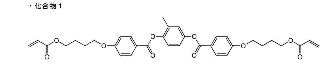

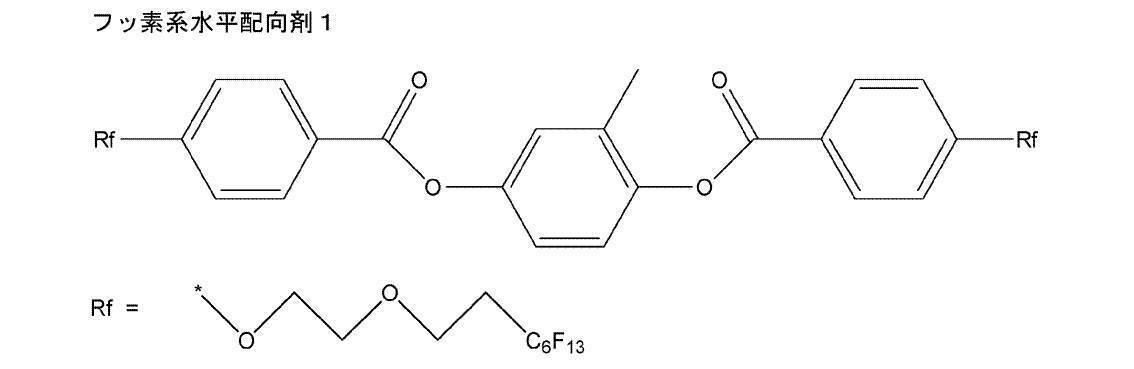
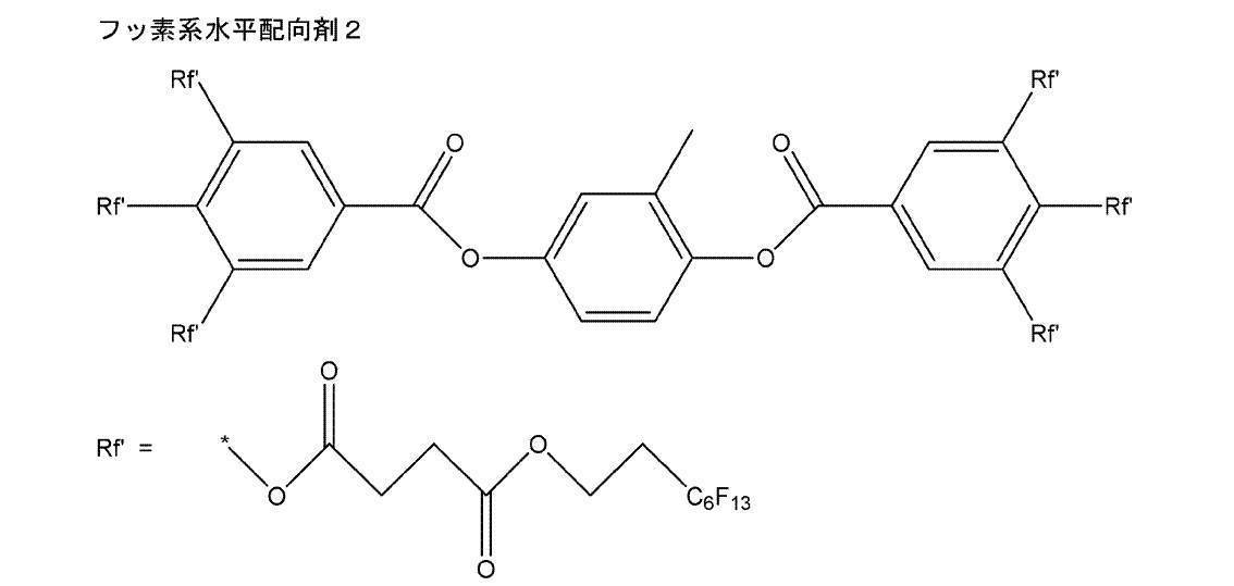
化合物1、化合物群B中の化合物2、フッ素系水平配向剤、キラル剤、重合開始剤、および、溶剤を混合し、下記組成の塗布液(L1)を調製した。
・上記化合物1 80質量部
・上記化合物群B中の化合物2 20質量部
・上記フッ素系水平配向剤1 0.1質量部
・上記フッ素系水平配向剤2 0.007質量部
・下記左旋回性キラル剤(A) 4.5質量部
・重合開始剤IRGACURE819(BASF社製)
4質量部
・溶剤(シクロヘキサノン) 溶質濃度が40質量%となる量 <Preparation of coating liquid (L1)>
Compound 1, compound 2 in compound group B, fluorine-based horizontal alignment agent, chiral agent, polymerization initiator, and solvent were mixed to prepare a coating liquid (L1) having the following composition.
-80 parts by mass of the above compound 1-20 parts by mass of the compound 2 in the above compound group B-0.1 parts by mass of the above-mentioned fluorine-based horizontal alignment agent 1-0.007 parts by mass of the above-mentioned fluorine-based horizontal alignment agent 2-The following left-turning property Chiral agent (A) 4.5 parts by mass / polymerization initiator IRGACURE819 (manufactured by BASF)
4 parts by mass / solvent (cyclohexanone) Amount at which the solute concentration becomes 40% by mass
化合物1、化合物群B中の化合物2、フッ素系水平配向剤、キラル剤、重合開始剤、および、溶剤を混合し、下記組成の塗布液(L2)を調製した。
・上記化合物1 80質量部
・上記化合物群B中の化合物2 20質量部
・上記フッ素系水平配向剤1 0.1質量部
・上記フッ素系水平配向剤2 0.007質量部
・下記左旋回性キラル剤(A) 5質量部
・重合開始剤IRGACURE819(BASF社製)
4質量部
・溶剤(シクロヘキサノン) 溶質濃度が40質量%となる量 <Preparation of coating liquid (L2)>
Compound 1, compound 2 in compound group B, fluorine-based horizontal alignment agent, chiral agent, polymerization initiator, and solvent were mixed to prepare a coating liquid (L2) having the following composition.
-80 parts by mass of the above compound 1-20 parts by mass of the compound 2 in the above compound group B-0.1 parts by mass of the above-mentioned fluorine-based horizontal alignment agent 1-0.007 parts by mass of the above-mentioned fluorine-based horizontal alignment agent 2-The following left-turning property 5 parts by mass of chiral agent (A) / polymerization initiator IRGACURE819 (manufactured by BASF)
4 parts by mass / solvent (cyclohexanone) Amount at which the solute concentration becomes 40% by mass
化合物1、化合物群B中の化合物2、フッ素系水平配向剤、キラル剤、重合開始剤、および、溶剤を混合し、下記組成の塗布液(L3)を調製した。
・上記化合物1 80質量部
・上記化合物群B中の化合物2 20質量部
・上記フッ素系水平配向剤1 0.1質量部
・上記フッ素系水平配向剤2 0.007質量部
・下記左旋回性キラル剤(A) 5.5質量部
・重合開始剤IRGACURE819(BASF社製)
4質量部
・溶剤(シクロヘキサノン) 溶質濃度が40質量%となる量 <Preparation of coating solution (L3)>
Compound 1, compound 2 in compound group B, fluorine-based horizontal alignment agent, chiral agent, polymerization initiator, and solvent were mixed to prepare a coating liquid (L3) having the following composition.
-80 parts by mass of the above compound 1-20 parts by mass of the compound 2 in the above compound group B-0.1 parts by mass of the above-mentioned fluorine-based horizontal alignment agent 1-0.007 parts by mass of the above-mentioned fluorine-based horizontal alignment agent 2-The following left-turning property Chiral agent (A) 5.5 parts by mass / polymerization initiator IRGACURE819 (manufactured by BASF)
4 parts by mass / solvent (cyclohexanone) Amount at which the solute concentration becomes 40% by mass

(1)スピンコーターを用いて、乾燥後の塗膜の厚みが5μmになるように、塗布液(R1)をガラス基板上に室温にて塗布して、塗膜を形成した。
(2)塗膜を有するガラス基板を室温にて30秒間乾燥させて、塗膜から溶剤を除去した。次に、塗膜を有するガラス基板を90℃で2分間加熱し、コレステリック液晶相を形成した。次に、フージョンUVシステムズ(株)製無電極ランプ「Dバルブ」(90mW/cm2)を用いて、出力60%で6~12秒間、塗膜にUV(紫外線)照射し、コレステリック液晶相を固定してなるフィルム(F1)をガラス基板上に作製した。
また、塗布液(R1)の代わりに塗布液(L1)を用いた以外は上記と同様の方法で、フィルム(F1b)を作製した。 <Production of film>
(1) Using a spin coater, the coating solution (R1) was applied onto a glass substrate at room temperature so that the thickness of the dried coating film was 5 μm, thereby forming a coating film.
(2) The glass substrate having the coating film was dried at room temperature for 30 seconds to remove the solvent from the coating film. Next, the glass substrate having the coating film was heated at 90 ° C. for 2 minutes to form a cholesteric liquid crystal phase. Next, using a non-electrode lamp “D bulb” (90 mW / cm 2 ) manufactured by Fusion UV Systems Co., Ltd., the coating film was irradiated with UV (ultraviolet rays) at an output of 60% for 6 to 12 seconds to obtain a cholesteric liquid crystal phase. A fixed film (F1) was produced on a glass substrate.
A film (F1b) was produced in the same manner as described above except that the coating liquid (L1) was used instead of the coating liquid (R1).
(1)スピンコーターを用いて、乾燥後の塗膜の厚みが5μmになるように、塗布液(L1)をフィルム(F1)上に室温にて塗布して、塗膜を形成した。
(2)塗膜を有するフィルム(F1)を室温にて30秒間乾燥させて、塗膜から溶剤を除去した。次に、塗膜を有するフィルム(F1)を90℃で2分間加熱し、その後、塗膜の加熱温度を35℃にて、コレステリック液晶相を形成した。次に、フージョンUVシステムズ(株)製無電極ランプ「Dバルブ」(90mW/cm2)を用いて、出力60%で6~12秒間、塗膜にUV照射し、コレステリック液晶相を固定し、ガラス基板上にコレステリック液晶相を固定してなるフィルムを2層積層した積層体(A)を作製した。作製した積層体(A)には、顕著な欠陥およびスジがなく面状は良好であった。 <Preparation of laminate (part 1)>
(1) Using a spin coater, the coating solution (L1) was applied onto the film (F1) at room temperature so that the thickness of the dried coating film was 5 μm, thereby forming a coating film.
(2) The film (F1) having a coating film was dried at room temperature for 30 seconds to remove the solvent from the coating film. Next, the film (F1) having a coating film was heated at 90 ° C. for 2 minutes, and then a cholesteric liquid crystal phase was formed at a coating temperature of 35 ° C. Next, using an electrodeless lamp “D bulb” (90 mW / cm 2 ) manufactured by Fusion UV Systems Co., Ltd., the coating film was irradiated with UV at an output of 60% for 6 to 12 seconds to fix the cholesteric liquid crystal phase. A laminate (A) was produced in which two layers of films formed by fixing a cholesteric liquid crystal phase on a glass substrate were laminated. The produced laminate (A) had no noticeable defects and streaks and had a good surface shape.
フィルム(F1)および(F1b)の透過スペクトルを測定したところ、それぞれ選択反射波長は1075nmおよび1070nmであった。また、積層体(A)の透過スペクトルを測定したところ、1070nm付近に1つの強いピークが観測された。このことから、塗布液(R1)を用いて形成されるフィルム(光反射層)と、塗布液(L1)を用いて形成されるフィルム(光反射層)とは、互いに等しい選択反射波長を有することがわかった。
次に、積層体(A)のヘイズ値をヘイズメーターにより測定したところ、3回測定した平均値が0.3(%)であった。
さらに、塗布液(R1)および塗布液(L1)に用いたキラル剤のHTPを次式に従って算出した結果、それぞれ55μm-1および37μm-1であり、どちらもHTPは30μm-1以上であった。
式:HTP=1÷{(らせんピッチ長(μm))×(塗布液に含まれる固形分中のキラル剤の質量%濃度)}
(ただし、らせんピッチ長(μm)は(選択反射波長(μm))÷(塗布液に含まれる固形分の平均屈折率)で算出され、固形分の平均屈折率は1.5と仮定して算出した。)
なお、上記固形分は、塗布液に含まれる成分のうちフィルムを構成し得る成分を意図して、溶剤は含まれない。また、成分が液状であっても、フィルムを構成し得る場合は、固形分とする。 <Evaluation of film and laminate>
When the transmission spectra of the films (F1) and (F1b) were measured, the selective reflection wavelengths were 1075 nm and 1070 nm, respectively. Further, when the transmission spectrum of the laminate (A) was measured, one strong peak was observed in the vicinity of 1070 nm. From this, the film (light reflection layer) formed using the coating liquid (R1) and the film (light reflection layer) formed using the coating liquid (L1) have the same selective reflection wavelength. I understood it.
Next, when the haze value of the laminate (A) was measured with a haze meter, the average value measured three times was 0.3 (%).
Furthermore, the HTP of the chiral agent used in the coating liquid (R1) and the coating liquid (L1) results were calculated according to the following equation, are each 55 .mu.m -1 and 37 [mu] m -1, both HTP were 30 [mu] m -1 or more .
Formula: HTP = 1 ÷ {(spiral pitch length (μm)) × (mass% concentration of chiral agent in solid content contained in coating solution)}
(However, the helical pitch length (μm) is calculated by (selective reflection wavelength (μm)) ÷ (average refractive index of solid content in coating liquid), and the average refractive index of solid content is assumed to be 1.5. Calculated.)
In addition, the said solid content intends the component which can comprise a film among the components contained in a coating liquid, and a solvent is not contained. Moreover, even if a component is liquid, when it can comprise a film, it is set as solid content.
塗布液(R1)の代わりに塗布液(R2)、塗布液(R3)、塗布液(L2)、および、塗布液(L3)をそれぞれ用いた以外は、フィルム(F1)を作製した方法と同様の方法で、フィルム(F2)、(F3)、(F2b)、および、(F3b)をそれぞれ作製した。
左旋回性のキラル剤を含むフィルム(F2b)、および(F3b)の選択反射波長は、右旋回性のキラル剤を含むフィルム(F2)、および(F3)の選択反射波長とそれぞれ互いに等しかった。
前述の積層体(A)の作製法と同様に、積層体(A)上にフィルム(F2)とフィルム(F2b)を積層し、積層体(B)を作製した。
さらに、積層体(B)上にフィルム(F3)とフィルム(F3b)を積層することで、積層体(C)を作製した。
紫外可視近赤外分光光度計(日立ハイテクノロジーズ社製 U-4100)の分光光度計(ref.ガラス基板)を用いて、積層体(A)、積層体(B)、および、積層体(C)の波長400~1100nmの範囲における透過率を測定した。積層体(A)、積層体(B)、および、積層体(C)の測定結果を、それぞれ図5~7に示す。 <Production of laminate (part 2)>
Similar to the method for producing the film (F1) except that the coating liquid (R2), the coating liquid (R3), the coating liquid (L2), and the coating liquid (L3) were used instead of the coating liquid (R1). Films (F2), (F3), (F2b), and (F3b) were produced by the method described above.
The selective reflection wavelengths of the films (F2b) and (F3b) containing the left-turning chiral agent were equal to the selective reflection wavelengths of the films (F2) and (F3) containing the right-turning chiral agent, respectively. .
In the same manner as in the method for producing the laminate (A) described above, the film (F2) and the film (F2b) were laminated on the laminate (A) to produce a laminate (B).
Furthermore, the laminated body (C) was produced by laminating | stacking a film (F3) and a film (F3b) on a laminated body (B).
Using a spectrophotometer (ref. Glass substrate) of an ultraviolet-visible near-infrared spectrophotometer (U-4100 manufactured by Hitachi High-Technologies Corporation), a laminate (A), a laminate (B), and a laminate (C ) Was measured in the wavelength range of 400 to 1100 nm. The measurement results of the laminate (A), laminate (B), and laminate (C) are shown in FIGS. 5 to 7, respectively.
下記表1に示す組成の混合液を、0.3mm径のジルコニアビーズを使用して、ビーズミル(減圧機構付き高圧分散機NANO-3000-10(日本ビーイーイー(株)製))で、IR(赤外線)着色剤が表1に示す平均粒子径となるまで、混合して、顔料分散液を調製した。表には、該当する成分の使用量(単位:質量部)を示す。
顔料分散液中の顔料の平均粒子径は、日機装(株)製のMICROTRACUPA 150を用いて、体積基準で測定した。 <Preparation of pigment dispersion 1-1>
Using a zirconia bead having a diameter of 0.3 mm, a mixed solution having the composition shown in Table 1 below is subjected to IR (infrared ray) with a bead mill (high-pressure disperser NANO-3000-10 with a decompression mechanism (manufactured by Nippon BEE Co., Ltd.)). A pigment dispersion was prepared by mixing until the colorant had an average particle size shown in Table 1. The table shows the usage amount (unit: parts by mass) of the corresponding component.
The average particle size of the pigment in the pigment dispersion was measured on a volume
下記表1に示す組成の混合液を、0.3mm径のジルコニアビーズを使用して、ビーズミル(減圧機構付き高圧分散機NANO-3000-10(日本ビーイーイー(株)製))で、3時間混合して、顔料分散液を調製した。表には、該当する成分の使用量(単位:質量部)を示す。 <Preparation of pigment dispersions 2-1 to 2-4>
The mixed solution having the composition shown in Table 1 below is mixed for 3 hours using a zirconia bead having a diameter of 0.3 mm in a bead mill (high-pressure disperser NANO-3000-10 with a decompression mechanism (manufactured by Nippon BEE Co., Ltd.)). Thus, a pigment dispersion was prepared. The table shows the usage amount (unit: parts by mass) of the corresponding component.
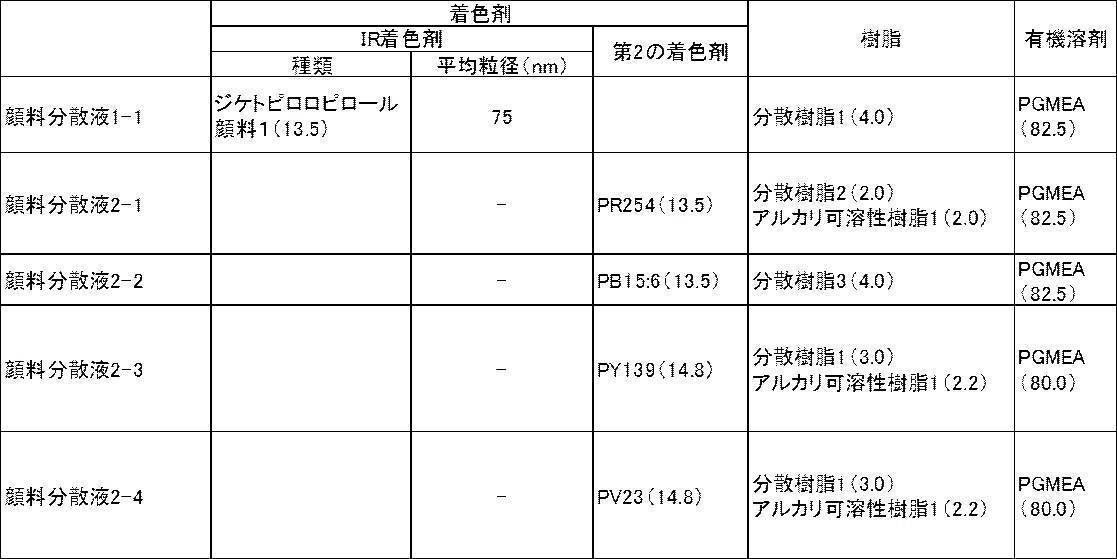
・ジケトピロロピロール顔料1:下記構造(特開2009-263614号公報に記載の方法で合成した)(波長800~900nmの範囲に吸収極大を有する着色剤)

Diketopyrrolopyrrole pigment 1: the following structure (synthesized by the method described in JP-A-2009-263614) (colorant having an absorption maximum in the wavelength range of 800 to 900 nm)
・PR254 : C.I.Pigment Red 254
・PB15:6 : C.I.Pigment Blue 15:6
・PY139 : Pigment Yellow 139
・PV23 : Pigment Violet 23 [Second colorant (colorant having an absorption maximum in the wavelength range of 400 to 700 nm)]
PR254: C.I. I. Pigment Red 254
-PB15: 6: C.I. I. Pigment Blue 15: 6
・ PY139: Pigment Yellow 139
・ PV23: Pigment Violet 23
・分散樹脂1:BYK-111(BYK社製)
・分散樹脂2:下記構造(重量平均分子量(Mw):7950)
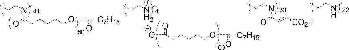

・アルカリ可溶性樹脂1:下記構造
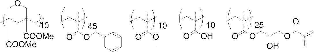
-Dispersing resin 1: BYK-111 (manufactured by BYK)
-Dispersing resin 2: the following structure (weight average molecular weight (Mw): 7950)
・ Alkali-soluble resin 1: the following structure
下記表2に示す成分を下記表2に示す割合(単位は質量部)で混合して、赤外線透過組成物Aを調製した。 <Preparation of infrared transmitting composition A>
The components shown in Table 2 below were mixed in the proportions shown in Table 2 below (units are parts by mass) to prepare an infrared transmitting composition A.

・重合性化合物1:M-305(トリアクリレートが55~63質量%)(東亜合成社製) 下記構造
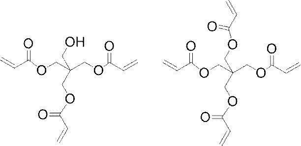
・光重合開始剤1:Irgacure OXE01(BASF社製) 下記構造
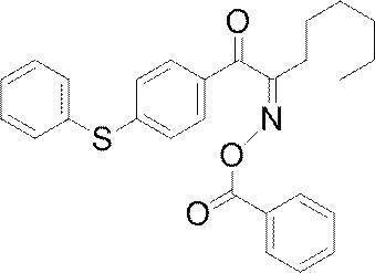
・界面活性剤1:含フッ素系界面活性剤
・重合禁止剤1:p-メトキシフェノール
・有機溶剤1:プロピレングリコールメチルエーテルアセテート
Polymerizable compound 1: M-305 (55 to 63% by mass of triacrylate) (manufactured by Toa Gosei Co., Ltd.)
Photopolymerization initiator 1: Irgacure OXE01 (manufactured by BASF)
・ Surfactant 1: Fluorine-containing surfactant ・ Polymerization inhibitor 1: p-methoxyphenol ・ Organic solvent 1: Propylene glycol methyl ether acetate
赤外線透過組成物Aを、ガラス基板上にスピンコートにて塗布した。次に、赤外線透過組成物Aが塗布されたガラス基板を、ホットプレートを用いて、100℃で120秒間乾燥し、さらに、200℃で300秒間加熱処理(ポストベーク)を行い、赤外線透過フィルムA(膜厚3.0μm)を得た。
紫外可視近赤外分光光度計(日立ハイテクノロジーズ社製 U-4100)の分光光度計(ref.ガラス基板)を用いて、赤外線透過フィルムAを有するガラス基板の波長400~1100nmの範囲における透過率を測定した。図8に、その結果を示す。 <Preparation of infrared transmission film A>
The infrared transmitting composition A was applied on a glass substrate by spin coating. Next, the glass substrate coated with the infrared transmitting composition A is dried at 100 ° C. for 120 seconds using a hot plate, and further subjected to a heat treatment (post-bake) at 200 ° C. for 300 seconds, whereby the infrared transmitting film A (Thickness of 3.0 μm) was obtained.
Using a spectrophotometer (ref. Glass substrate) of an ultraviolet-visible near-infrared spectrophotometer (U-4100 manufactured by Hitachi High-Technologies Corporation), the transmittance in a wavelength range of 400 to 1100 nm of a glass substrate having an infrared transmission film A Was measured. FIG. 8 shows the result.
下記組成の混合液を、0.3mm径のジルコニアビーズを使用して、ビーズミル(減圧機構付き高圧分散機NANO-3000-10(日本ビーイーイー(株)製))で、3時間混合して、顔料分散液B-1を調製した。
・赤色顔料(C.I.Pigment Red 254)および黄色顔料(C.I.Pigment Yellow 139)からなる混合顔料
11.8質量部
・分散剤:BYK社製 BYK-111 9.1質量部
・有機溶剤:プロピレングリコールメチルエーテルアセテート
79.1質量部 <Preparation of pigment dispersion B-1>
A mixed liquid having the following composition was mixed for 3 hours using a zirconia bead having a diameter of 0.3 mm with a bead mill (high pressure disperser NANO-3000-10 with a pressure reducing mechanism (manufactured by Nippon BEE Co., Ltd.)). Dispersion B-1 was prepared.
-11.8 parts by mass of a mixed pigment composed of a red pigment (CI Pigment Red 254) and a yellow pigment (CI Pigment Yellow 139)-Dispersant: BYK-111 manufactured by BYK 9.1 parts by mass-Organic Solvent: 79.1 parts by mass of propylene glycol methyl ether acetate
下記組成の混合液を、0.3mm径のジルコニアビーズを使用して、ビーズミル(減圧機構付き高圧分散機NANO-3000-10(日本ビーイーイー(株)製))で、3時間混合して、顔料分散液B-2を調製した。
・青色顔料(C.I.Pigment Blue 15:6)および紫色顔料(C.I.Pigment Violet 23)からなる混合顔料
12.6質量部
・分散剤:BYK社製 BYK-111 2.0質量部
・下記分散樹脂4 3.3質量部
・有機溶剤:シクロヘキサノン 31.2質量部
・有機溶剤:プロピレングリコールメチルエーテルアセテート(PGMEA) 50.9質量部 <Preparation of pigment dispersion B-2>
A mixed liquid having the following composition was mixed for 3 hours using a zirconia bead having a diameter of 0.3 mm in a bead mill (high-pressure disperser NANO-3000-10 with a pressure reducing mechanism (manufactured by Nippon BEE Co., Ltd.)) to obtain a pigment. Dispersion B-2 was prepared.
-12.6 parts by mass of a mixed pigment consisting of a blue pigment (CI Pigment Blue 15: 6) and a purple pigment (CI Pigment Violet 23)-Dispersant: BYK-111 2.0 parts by mass manufactured by BYK -Dispersing resin 4 below 3.3 parts by mass-Organic solvent: 31.2 parts by mass of cyclohexanone-Organic solvent: 50.9 parts by mass of propylene glycol methyl ether acetate (PGMEA)

下記の成分を混合して、赤外線透過組成物Bを調製した。
・顔料分散液B-1 46.5質量部
・顔料分散液B-2 37.1質量部
・上記アルカリ可溶性樹脂1 1.1質量部
・下記重合性化合物2 1.8質量部
・下記重合性化合物3 0.6質量部
・光重合開始剤:下記光重合開始剤2 0.9質量部
・界面活性剤1:含フッ素系界面活性剤 4.2質量部
・重合禁止剤:p-メトキシフェノール 0.001質量部
・有機溶剤1:PGMEA 7.8質量部 <Preparation of infrared transmitting composition B>
The following components were mixed to prepare an infrared transmitting composition B.
-Pigment dispersion B-1 46.5 parts by mass-Pigment dispersion B-2 37.1 parts by mass-1.1 parts by mass of the alkali-soluble resin 1-1.8 parts by mass of the following polymerizable compound 2-The following polymerizability Compound 3 0.6 parts by weight Photopolymerization initiator: 0.9 parts by weight of the following photopolymerization initiator 2 Surfactant 1: Fluorine-containing surfactant 4.2 parts by weight Polymerization inhibitor: p-methoxyphenol 0.001 part by mass / organic solvent 1: PGMEA 7.8 parts by mass


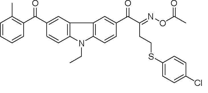
赤外線透過組成物Bを、ガラス基板上にスピンコートにて塗布した。次に、赤外線透過組成物Bが塗布されたガラス基板を、ホットプレートを用いて、100℃で120秒間乾燥し、さらに、200℃で300秒間加熱処理(ポストベーク)を行い、赤外線透過フィルムB(膜厚1.0μm)を得た。
紫外可視近赤外分光光度計(日立ハイテクノロジーズ社製 U-4100)の分光光度計(ref.ガラス基板)を用いて、赤外線透過フィルムBを有するガラス基板の波長400~1100nmの範囲における透過率を測定した。図9に、その結果を示す。 <Preparation of infrared transmission film B>
Infrared transmitting composition B was applied on a glass substrate by spin coating. Next, the glass substrate coated with the infrared transmitting composition B is dried at 100 ° C. for 120 seconds using a hot plate, and further subjected to a heat treatment (post-bake) at 200 ° C. for 300 seconds. (Film thickness 1.0 μm) was obtained.
Using a spectrophotometer (ref. Glass substrate) of an ultraviolet-visible near-infrared spectrophotometer (U-4100 manufactured by Hitachi High-Technologies Corporation), the transmittance in the wavelength range of 400 to 1100 nm of the glass substrate having the infrared transmission film B Was measured. FIG. 9 shows the result.
特開2013-077009号公報の段落0255~0259の記載(実施例1)に従ってカラーフィルター(赤外線透過フィルムC)を作製した。
紫外可視近赤外分光光度計(日立ハイテクノロジーズ社製 U-4100)の分光光度計(ref.ガラス基板)を用いて、赤外線透過フィルムCを有する基板の波長400~1100nmの範囲における透過率を測定した。図10に、その結果を示す。 <Preparation of infrared transmission film C>
A color filter (infrared transmitting film C) was produced according to the description (Example 1) in paragraphs 0255 to 0259 of JP2013-077009A.
Using a spectrophotometer (ref. Glass substrate) of an ultraviolet-visible near-infrared spectrophotometer (U-4100, manufactured by Hitachi High-Technologies Corporation), the transmittance in the wavelength range of 400 to 1100 nm of the substrate having the infrared transmission film C was measured. It was measured. FIG. 10 shows the result.
上記積層体(A)の作製手順(<積層体の作製(その1)>)、および、上記赤外線透過フィルムAの作製手順(上記<赤外線透過フィルムAの作製>)に従って、基板上に積層体(A)および赤外線透過フィルムAをこの順で形成し、バンドパスフィルターAを作製した。
紫外可視近赤外分光光度計(日立ハイテクノロジーズ社製 U-4100)の分光光度計(ref.ガラス基板)を用いて、バンドパスフィルターAの波長400~1100nmの範囲における透過率を測定した。図11に、その結果を示す。
[実施例2:バンドパスフィルターB]
上記積層体(B)の作製手順(<積層体の作製(その2)>)、および、上記赤外線透過フィルムBの作製手順(上記<赤外線透過フィルムBの作製>)に従って、基板上に積層体(B)および赤外線透過フィルムBを形成し、バンドパスフィルターBを作製した。
紫外可視近赤外分光光度計(日立ハイテクノロジーズ社製 U-4100)の分光光度計(ref.ガラス基板)を用いて、バンドパスフィルターBの波長400~1100nmの範囲における透過率を測定した。図12に、その結果を示す。
[実施例3:バンドパスフィルターC]
上記積層体(C)の作製手順(<積層体の作製(その2)>)、および、上記赤外線透過フィルムCの作製手順(上記<赤外線透過フィルムCの作製>)に従って、基板上に積層体(C)および赤外線透過フィルムCを形成し、バンドパスフィルターCを作製した。
紫外可視近赤外分光光度計(日立ハイテクノロジーズ社製 U-4100)の分光光度計(ref.ガラス基板)を用いて、バンドパスフィルターCの波長400~1100nmの範囲における透過率を測定した。図13に、その結果を示す。 [Example 1: Bandpass filter A]
In accordance with the production procedure of the laminate (A) (<production of the laminate (part 1)>) and the production procedure of the infrared transmission film A (<production of the infrared transmission film A>), the laminate on the substrate. (A) and the infrared transmission film A were formed in this order, and the band pass filter A was produced.
Using a spectrophotometer (ref. Glass substrate) of an ultraviolet-visible near-infrared spectrophotometer (U-4100, manufactured by Hitachi High-Technologies Corporation), the transmittance of the bandpass filter A in the wavelength range of 400 to 1100 nm was measured. FIG. 11 shows the result.
[Example 2: Bandpass filter B]
In accordance with the production procedure of the laminate (B) (<production of the laminate (part 2)>) and the production procedure of the infrared transmission film B (<production of the infrared transmission film B>), the laminate on the substrate. (B) and the infrared transmission film B were formed, and the band pass filter B was produced.
Using a spectrophotometer (ref. Glass substrate) of an ultraviolet-visible near-infrared spectrophotometer (U-4100, manufactured by Hitachi High-Technologies Corporation), the transmittance of the bandpass filter B in the wavelength range of 400 to 1100 nm was measured. FIG. 12 shows the result.
[Example 3: Bandpass filter C]
In accordance with the procedure for producing the laminate (C) (<production of laminate (part 2)>) and the procedure for producing infrared transmission film C (<production of infrared transmission film C>), the laminate on the substrate. (C) and the infrared transmission film C were formed, and the band pass filter C was produced.
Using a spectrophotometer (ref. Glass substrate) of an ultraviolet-visible near-infrared spectrophotometer (U-4100, manufactured by Hitachi High-Technologies Corporation), the transmittance of the bandpass filter C in the wavelength range of 400 to 1100 nm was measured. FIG. 13 shows the result.
蒸着法により、基板上にTiO2からなる高屈折率層とSiO2からなる低屈折率層とを交互に配置して、透過波長が850nmであるバンドパスフィルターを作製した。 [Comparative Example 1: Deposition laminate]
A high-refractive index layer made of TiO 2 and a low-refractive index layer made of SiO 2 were alternately arranged on the substrate by vapor deposition to produce a bandpass filter having a transmission wavelength of 850 nm.
<塗布液の調製>
化合物1、化合物群B中の化合物2、フッ素系水平配向剤、重合開始剤、および、溶剤を下記のとおり混合し、さらにキラル剤の種類と濃度を下記表3のとおりに混合した各種塗布液を調製した。
・上記化合物1 80質量部
・上記化合物群B中の化合物2 20質量部
・上記フッ素系水平配向剤1 0.1質量部
・上記フッ素系水平配向剤2 0.003質量部
・重合開始剤IRGACURE819(BASF社製) 3質量部
・溶剤(メチルエチルケトン) 溶質濃度が30質量%となる量 [Comparative Example 2]
<Preparation of coating solution>
Compound 1, Compound 2 in Compound Group B, Fluorine Horizontal Alignment Agent, Polymerization Initiator, and Solvent are mixed as follows, and the types and concentrations of chiral agents are mixed as shown in Table 3 below. Was prepared.
-80 parts by mass of the above-mentioned compound 1-20 parts by mass of the compound 2 in the above-mentioned compound group B-0.1 parts by mass of the above-mentioned fluorine-based horizontal aligning agent 1-0.003 parts by mass of the above-mentioned fluoro-based horizontal aligning agent 2 (Made by BASF) 3 parts by mass / solvent (methyl ethyl ketone) Amount at which the solute concentration becomes 30% by mass

PET(Polyethylene Terephthalate)フィルム(下塗り層無し、富士フイルム(株)製、厚み:50μm、大きさ320mm×400mm)の表面上に直接、ラビング処理(レーヨン布、圧力:0.1kgf、回転数:1000rpm、搬送速度:10m/min、回数:1往復)を施し、次いで、塗布液(R4)を用い、下記の手順にてコレステリック液晶相を固定し、さらに塗布液(L4)を用いて、コレステリック液晶相を固定してなる層を二層積層してなる液晶膜を製造した。この液晶膜は、可視光線反射層として機能する。
(1)乾燥後の塗膜の厚みが5μmになるように、ワイヤーバーを用いて、塗布液(R4)をPETフィルム上に室温にて塗布し、塗膜を形成した。
(2)塗膜が配置されたPETフィルムを室温にて30秒間乾燥させて、塗膜から溶剤を除去した。次に、塗膜が配置されたPETフィルムを90℃で2分間加熱し、その後、塗膜の加熱温度を35℃にて、コレステリック液晶相を形成した。次に、フージョンUVシステムズ(株)製無電極ランプ「Dバルブ」(90mW/cm2)を用いて、出力60%で6~12秒間、塗膜にUV照射し、コレステリック液晶相を固定してなるフィルム(F4)をPETフィルム上に作製した。
(3)乾燥後の塗膜の厚みが5μmになるように、ワイヤーバーを用いて、塗布液(L4)を上記(2)で作製したフィルム(F4)上に、室温にて塗布し、塗膜を形成した。
(4)塗膜が配置されたPETフィルムを室温にて30秒間乾燥させて、塗膜から溶剤を除去した。次に、塗膜が配置されたPETフィルムを90℃で2分間加熱し、その後、塗膜の加熱温度を35℃にて、コレステリック液晶相を形成した。次に、フージョンUVシステムズ(株)製無電極ランプ「Dバルブ」(90mW/cm2)を用いて、出力60%で6~12秒間、塗膜にUV照射し、コレステリック液晶相を固定し、PETフィルム上にコレステリック液晶相を固定してなるフィルムを2層積層した積層体(G4)を作製した。作製した積層体(G4)には、顕著な欠陥およびスジがなく面状は良好であった。また、積層体(G4)を黒い紙の上におくと強い選択反射色が確認された。
また、塗布液(R4)を塗布液(L4)に変更した以外は上記(1)および(2)の工程と同様にして、フィルム(F4b)を作製した。
また、塗布液(R4)を塗布液(R1-1)、(R5)~(R10)に変更した以外は上記(1)および(2)の工程と同様にして、フィルム(F1-1)、(F5)~(F10)をそれぞれ作製した。
また、フィルム(F4b)の作製において、塗布液(L4)を塗布液(L1-1)、(L5)~(L10)に変更した以外はフィルム(F4b)の作製と同様にして、フィルム(F1-1b)、(F5b)~(F10b)を作製した。
また、1層目塗布液と2層目塗布液を下記表3に記載のものに変更した以外は、上記(1)~(4)の工程と同様にして、積層体(G1-1)、(G5)~(G10)を作製した。 <Production of laminate>
A rubbing treatment (rayon cloth, pressure: 0.1 kgf, rotation speed: 1000 rpm) directly on the surface of a PET (Polyethylene Terephthalate) film (no undercoat layer, manufactured by FUJIFILM Corporation, thickness: 50 μm,
(1) The coating liquid (R4) was applied on a PET film at room temperature using a wire bar so that the thickness of the dried coating film was 5 μm, thereby forming a coating film.
(2) The PET film on which the coating film was disposed was dried at room temperature for 30 seconds to remove the solvent from the coating film. Next, the PET film on which the coating film was disposed was heated at 90 ° C. for 2 minutes, and then the cholesteric liquid crystal phase was formed at a heating temperature of the coating film of 35 ° C. Next, using an electrodeless lamp “D bulb” (90 mW / cm 2 ) manufactured by Fusion UV Systems Co., Ltd., the coating film was irradiated with UV at an output of 60% for 6 to 12 seconds to fix the cholesteric liquid crystal phase. The resulting film (F4) was prepared on a PET film.
(3) Using a wire bar, apply the coating liquid (L4) on the film (F4) prepared in (2) above at room temperature so that the thickness of the dried coating film becomes 5 μm. A film was formed.
(4) The PET film on which the coating film was disposed was dried at room temperature for 30 seconds to remove the solvent from the coating film. Next, the PET film on which the coating film was disposed was heated at 90 ° C. for 2 minutes, and then the cholesteric liquid crystal phase was formed at a heating temperature of the coating film of 35 ° C. Next, using an electrodeless lamp “D bulb” (90 mW / cm 2 ) manufactured by Fusion UV Systems Co., Ltd., the coating film was irradiated with UV at an output of 60% for 6 to 12 seconds to fix the cholesteric liquid crystal phase. A laminate (G4) was produced by laminating two layers of films formed by fixing a cholesteric liquid crystal phase on a PET film. The produced laminate (G4) was free of significant defects and streaks and had a good surface shape. Further, when the laminate (G4) was placed on black paper, a strong selective reflection color was confirmed.
Further, a film (F4b) was produced in the same manner as in the steps (1) and (2) except that the coating solution (R4) was changed to the coating solution (L4).
The film (F1-1), the same as the steps (1) and (2) except that the coating solution (R4) was changed to coating solutions (R1-1) and (R5) to (R10). (F5) to (F10) were produced.
In the production of the film (F4b), the film (F1b) was prepared in the same manner as in the production of the film (F4b) except that the coating liquid (L4) was changed to the coating liquids (L1-1) and (L5) to (L10). -1b) and (F5b) to (F10b) were produced.
In addition, the laminate (G1-1), (G5) to (G10) were produced.
また、積層体(G1-1)、(G4)~(G10)のヘイズ値をヘイズメーターにより測定し、3回測定した平均値を以下表4に示す。
なお、左旋回性のキラル剤を含むフィルム(F1-1b)、(F5b)~(F10b)の選択反射波長は、右旋回性のキラル剤を含むフィルム(F1-1)、(F5)~(F10)の選択反射波長とそれぞれ互いに等しいことを確認した。 The produced laminates (G1-1) and (G4) to (G10) were free of significant defects and streaks and had a good surface shape. In addition, when the laminates (G1-1) and (G4) to (G7) were placed on black paper, strong selective reflection colors were confirmed.
Further, the haze values of the laminates (G1-1) and (G4) to (G10) were measured with a haze meter, and the average values measured three times are shown in Table 4 below.
The selective reflection wavelengths of the films (F1-1b) and (F5b) to (F10b) containing the left-turning chiral agent are the films (F1-1) and (F5) to (F5b) It was confirmed that the selective reflection wavelengths of (F10) were equal to each other.

積層体(G1-1)、(G4)~(G10)の透過スペクトルを測定した結果を図14に示した。積層体(G4)~(G7)を構成するそれぞれ2つのフィルムは互いに等しい選択反射波長であるため、積層体の透過スペクトルは表4に示す選択反射波長において1つの強いピークが観測され、高い反射性能を有することがわかった。 <Transmission spectrum evaluation>
The results of measuring the transmission spectra of the laminates (G1-1) and (G4) to (G10) are shown in FIG. Since each of the two films constituting the laminates (G4) to (G7) has the same selective reflection wavelength, the transmission spectrum of the laminate exhibits one strong peak at the selective reflection wavelength shown in Table 4, and high reflection. It was found to have performance.
積層体(G1-1)の上に両面粘着シート(PDS-1、リンテック社製)を貼り、もう一方の粘着面にPETフィルム上の積層体(G4)を貼り合わせ、PETフィルムを剥がして積層フィルムを作製した。さらに、同様の方法で、積層体(G5)~(G10)を貼り合わせて、組合せ体(G13)を作製した。
組合せ体(G13)の透過スペクトルを測定した結果を図15に示す。 <Production of combination G13>
A double-sided PSA sheet (PDS-1, manufactured by Lintec) is pasted on the laminate (G1-1), a laminate (G4) on the PET film is pasted on the other adhesive surface, and the PET film is peeled off and laminated. A film was prepared. Further, in the same manner, the laminates (G5) to (G10) were bonded to produce a combined body (G13).
The result of measuring the transmission spectrum of the combination (G13) is shown in FIG.
上記で作製した組合せ体(G13)と積層体(B)とを組み合わせることにより、850nmのバンドパスフィルターを作製した。層数は20層であった。 (Preparation of a band-pass filter using only the liquid crystal of the comparative example)
By combining the combination (G13) prepared above and the laminate (B), a 850 nm bandpass filter was prepared. The number of layers was 20.
上記で作製された各バンドパスフィルターを用いて、以下の評価を実施した。
(作製容易性)
形成されたバンドパスフィルターの層数が10層以下である場合を「A」、10層超である場合を「B」とした。
(角度依存性)
各実施例および比較例にて得られたバンドパスフィルターを用いて、バンドパスフィルターの表面に対する入射角を垂直(角度0度)と30度とにして、透過帯域の半値波長のシフト量を、下記基準に従って評価した。なお、上記シフト量とは、より具体的には、垂直方向から入射した際の半値波長Xと、斜め方向から入射した際の半値波長Yとの差を意図する。
2:5nm未満
1:5nm以上
なお、透過帯域の半値波長とは、透過帯域中の最大透過率(Tmax)に対して、透過率が50%((Tmax)×0.5)となるときの波長を意味し、半値波長のうち短波長側の半値波長を半値波長A、長波長側の半値波長を半値波長Bとがある。
本評価においては、半値波長Aを用いた上記評価が「2」であった場合を「A」とし、「1」であった場合を「B」とする。 [Evaluation]
The following evaluation was carried out using each bandpass filter produced above.
(Easy to manufacture)
The case where the number of layers of the formed bandpass filter was 10 layers or less was designated as “A”, and the case where the number was more than 10 layers was designated as “B”.
(Angle dependence)
Using the bandpass filters obtained in each of the examples and comparative examples, the incident angle with respect to the surface of the bandpass filter is vertical (
2: less than 5 nm 1: 5 nm or more Note that the half-value wavelength of the transmission band is when the transmittance is 50% ((Tmax) × 0.5) with respect to the maximum transmittance (Tmax) in the transmission band. This means a wavelength. Among the half-value wavelengths, the half-value wavelength on the short wavelength side is half-value wavelength A, and the half-value wavelength on the long wavelength side is half-value wavelength B.
In this evaluation, the case where the evaluation using the half-value wavelength A is “2” is “A”, and the case where it is “1” is “B”.


化合物2-11、下記フッ素系水平配向剤、キラル剤、重合開始剤、および、溶剤を混合し、下記組成の塗布液(R1-2)を調製した。なお、以下の化合物2-11の屈折率異方性Δnは、0.375であった。
・化合物2-11 100質量部
・上記フッ素系水平配向剤1 0.1質量部
・上記フッ素系水平配向剤2 0.007質量部
・右旋回性キラル剤LC756(BASF社製) 2.2質量部
・重合開始剤:アデカクルーズNCI-831(ADEKA社製)4質量部
・溶剤(シクロヘキサノン) 溶質濃度が40質量%となる量 <Preparation of coating solution (R1-2)>
Compound 2-11, the following fluorine-based horizontal alignment agent, chiral agent, polymerization initiator, and solvent were mixed to prepare a coating liquid (R1-2) having the following composition. The refractive index anisotropy Δn of the following compound 2-11 was 0.375.
-Compound 2-11 100 parts by mass-0.1 part by mass of the above-mentioned fluorine-based horizontal alignment agent 1-0.007 parts by mass of the above-mentioned fluorine-based horizontal alignment agent 2-Right-turning chiral agent LC756 (manufactured by BASF) 2.2 Part by mass / polymerization initiator: Adeka Cruz NCI-831 (manufactured by ADEKA) 4 parts by mass / solvent (cyclohexanone) Amount at which the solute concentration is 40% by mass

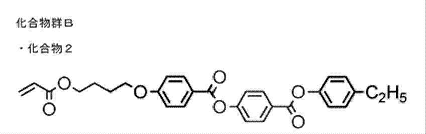
また、右旋回性キラル剤LC756の量を2.2質量部から3.0質量部に代えた以外は、上記塗布液(R1-2)と同様にして、塗布液(R3-2)を調製した。 Further, the coating liquid (R2-2) was prepared in the same manner as the coating liquid (R1-2) except that the amount of the right-turning chiral agent LC756 was changed from 2.2 parts by mass to 2.5 parts by mass. Prepared.
Further, the coating solution (R3-2) was prepared in the same manner as the coating solution (R1-2) except that the amount of the right-turning chiral agent LC756 was changed from 2.2 parts by mass to 3.0 parts by mass. Prepared.
化合物2-11、下記フッ素系水平配向剤、キラル剤、重合開始剤、および、溶剤を混合し、下記組成の塗布液(L1-2)を調製した。
・上記化合物2-11 100質量部
・上記フッ素系水平配向剤1 0.1質量部
・上記フッ素系水平配向剤2 0.007質量部
・下記左旋回性キラル剤(A) 3.3質量部
・重合開始剤:アデカクルーズNCI-831(ADEKA社製)4質量部
・溶剤(シクロヘキサノン) 溶質濃度が40質量%となる量 <Preparation of coating solution (L1-2)>
Compound 2-11, the following fluorine-based horizontal alignment agent, chiral agent, polymerization initiator, and solvent were mixed to prepare a coating liquid (L1-2) having the following composition.
-100 parts by mass of the above compound 2-11-0.1 parts by mass of the above-mentioned fluorine-based horizontal alignment agent 1-0.007 parts by mass of the above-mentioned fluorine-based horizontal alignment agent 2-3.3 parts by mass of the following left-turning chiral agent (A)・ Polymerization initiator: 4 parts by mass of Adeka Cruz NCI-831 (manufactured by ADEKA) ・ Solvent (cyclohexanone) Amount of solute concentration of 40% by mass
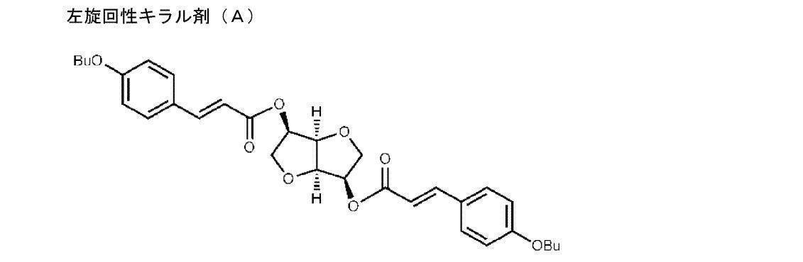
また、左旋回性キラル剤(A)の量を3.3質量部から4.5質量部に代えた以外は、上記塗布液(R1-2)と同様にして、塗布液(L3-2)を調製した。 Also, the coating liquid (L2-2) was the same as the coating liquid (R1-2) except that the amount of the left-turning chiral agent (A) was changed from 3.3 parts by mass to 3.8 parts by mass. Was prepared.
Also, the coating liquid (L3-2) was the same as the coating liquid (R1-2) except that the amount of the left-turning chiral agent (A) was changed from 3.3 parts by mass to 4.5 parts by mass. Was prepared.
塗布液(R1)の代わりに塗布液(R2)、(R3)、(R1-2)、(R2-2)、(R3-2)、(L2)、(L3)、(L1-2)、(L2-2)、および、(L3-2)をそれぞれ用いた以外は、フィルム(F1)を作製した方法と同様の方法で、フィルム(F2)、(F3)、(F1-2)、(F2-2)、(F3-2)、(F2b)、(F3b)、(F1-2b)、(F2-2b)、および、(F3-2b)をそれぞれ作製した。
左旋回性のキラル剤を含むフィルム(F2b)、(F3b)、(F1-2b)、(F2-2b)、および、(F3-2b)の選択反射波長は、右旋回性のキラル剤を含むフィルム(F2)、(F3)、(R1-2)、(R2-2)、および、(R3-2)の選択反射波長とそれぞれ互いに等しかった。
前述の積層体(A)の作製法と同様に、積層体(A)上にフィルム(F2)とフィルム(F2b)を積層し、積層体(B)を作製した。
さらに、積層体(B)上にフィルム(F3)とフィルム(F3b)を積層することで、積層体(C)を作製した。
さらに、積層体(C)上にフィルム(F1-2)とフィルム(F1-2b)を積層することで、積層体(D)を作製した。
さらに、積層体(D)上にフィルム(F2-2)とフィルム(F2-2b)を積層することで、積層体(E)を作製した。
さらに、積層体(E)上にフィルム(F3-2)とフィルム(F3-2b)を積層することで、積層体(F)を作製した。 <Preparation of laminate (part 3)>
Instead of the coating liquid (R1), the coating liquids (R2), (R3), (R1-2), (R2-2), (R3-2), (L2), (L3), (L1-2), Films (F2), (F3), (F1-2), (F2), (F1-2), (F1-2), (F1-2), (F1-2), (L1-2) F2-2), (F3-2), (F2b), (F3b), (F1-2b), (F2-2b), and (F3-2b) were prepared, respectively.
Selective reflection wavelengths of films (F2b), (F3b), (F1-2b), (F2-2b), and (F3-2b) containing a left-turning chiral agent The selective reflection wavelengths of the containing films (F2), (F3), (R1-2), (R2-2), and (R3-2) were equal to each other.
In the same manner as in the method for producing the laminate (A) described above, the film (F2) and the film (F2b) were laminated on the laminate (A) to produce a laminate (B).
Furthermore, the laminated body (C) was produced by laminating | stacking a film (F3) and a film (F3b) on a laminated body (B).
Further, the laminate (D) was produced by laminating the film (F1-2) and the film (F1-2b) on the laminate (C).
Further, the laminate (E) was produced by laminating the film (F2-2) and the film (F2-2b) on the laminate (D).
Further, the laminate (F) was produced by laminating the film (F3-2) and the film (F3-2b) on the laminate (E).
上記積層体(D)の作製手順(<積層体の作製(その3)>)、および、上記赤外線透過フィルムAの作製手順(上記<赤外線透過フィルムAの作製>)に従って、基板上に積層体(D)および赤外線透過フィルムAを形成し、バンドパスフィルターDを作製した。
紫外可視近赤外分光光度計(日立ハイテクノロジーズ社製 U-4100)の分光光度計(ref.ガラス基板)を用いて、バンドパスフィルターAの波長400~1100nmの範囲における透過率を測定した。図16に、その結果を示す。
[実施例5:バンドパスフィルターE]
上記積層体(E)の作製手順(<積層体の作製(その3)>)、および、上記赤外線透過フィルムBの作製手順(上記<赤外線透過フィルムBの作製>)に従って、基板上に積層体(E)および赤外線透過フィルムBを形成し、バンドパスフィルターEを作製した。
紫外可視近赤外分光光度計(日立ハイテクノロジーズ社製 U-4100)の分光光度計(ref.ガラス基板)を用いて、バンドパスフィルターBの波長400~1100nmの範囲における透過率を測定した。図17に、その結果を示す。
[実施例3:バンドパスフィルターF]
上記積層体(F)の作製手順(<積層体の作製(その3)>)、および、上記赤外線透過フィルムCの作製手順(上記<赤外線透過フィルムCの作製>)に従って、基板上に積層体(F)および赤外線透過フィルムCを形成し、バンドパスフィルターFを作製した。
紫外可視近赤外分光光度計(日立ハイテクノロジーズ社製 U-4100)の分光光度計(ref.ガラス基板)を用いて、バンドパスフィルターCの波長400~1100nmの範囲における透過率を測定した。図18に、その結果を示す。 [Example 4: band pass filter D]
In accordance with the production procedure of the laminate (D) (<production of laminate (part 3)>) and the production procedure of infrared transmission film A (<production of infrared transmission film A>), the laminate on the substrate. (D) and the infrared transmission film A were formed, and the band pass filter D was produced.
Using a spectrophotometer (ref. Glass substrate) of an ultraviolet-visible near-infrared spectrophotometer (U-4100, manufactured by Hitachi High-Technologies Corporation), the transmittance of the bandpass filter A in the wavelength range of 400 to 1100 nm was measured. FIG. 16 shows the result.
[Example 5: Bandpass filter E]
In accordance with the production procedure of the laminate (E) (<production of the laminate (part 3)>) and the production procedure of the infrared transmission film B (<production of the infrared transmission film B>), the laminate on the substrate (E) and the infrared transmission film B were formed, and the band pass filter E was produced.
Using a spectrophotometer (ref. Glass substrate) of an ultraviolet-visible near-infrared spectrophotometer (U-4100, manufactured by Hitachi High-Technologies Corporation), the transmittance of the bandpass filter B in the wavelength range of 400 to 1100 nm was measured. FIG. 17 shows the result.
[Example 3: Bandpass filter F]
According to the production procedure of the laminate (F) (<production of the laminate (part 3)>) and the production procedure of the infrared transmission film C (<production of the infrared transmission film C>), the laminate on the substrate. (F) and the infrared transmission film C were formed, and the band pass filter F was produced.
Using a spectrophotometer (ref. Glass substrate) of an ultraviolet-visible near-infrared spectrophotometer (U-4100, manufactured by Hitachi High-Technologies Corporation), the transmittance of the bandpass filter C in the wavelength range of 400 to 1100 nm was measured. FIG. 18 shows the result.


なお、一般式(1)で表される化合物で表される化合物を用いた場合も、実施例1と同様の結果が得られた。 As shown in the above results, it was confirmed that the desired effect was obtained according to the composition kit and laminate of the present invention.
In addition, also when the compound represented by the compound represented by General formula (1) was used, the result similar to Example 1 was obtained.
10,10a,10b 積層体
12 基板
14 多層反射膜
16 光吸収層
18a,20a,22a 光反射層Xa
18b,20b,22b 光反射層Xb
110 固体撮像素子
120 信号処理部
130 信号切替部
140 制御部
150 信号蓄積部
160 発光制御部
170 赤外LED
180、181:画像出力部 DESCRIPTION OF SYMBOLS 1 Lens
18b, 20b, 22b Light reflecting layer Xb
DESCRIPTION OF
180, 181: Image output unit
Claims (31)
- 重合性基を有する液晶化合物および右旋回性のキラル剤を含む第1組成物と、
重合性基を有する液晶化合物および左旋回性のキラル剤を含む第2組成物と、
色材を含む第3組成物と、を含む組成物キット。 A first composition comprising a liquid crystal compound having a polymerizable group and a right-turning chiral agent;
A second composition comprising a liquid crystal compound having a polymerizable group and a left-turning chiral agent;
And a third composition containing a coloring material. - 前記右旋回性のキラル剤の螺旋捩れ力が30μm-1以上である、請求項1に記載の組成物キット。 The composition kit according to claim 1, wherein the helical twisting force of the right-turning chiral agent is 30 μm −1 or more.
- 前記左旋回性のキラル剤の螺旋捩れ力が30μm-1以上である、請求項1または2に記載の組成物キット。 The composition kit according to claim 1 or 2, wherein the helical twisting force of the left-turning chiral agent is 30 µm -1 or more.
- 前記左旋回性のキラル剤が、一般式(1)で表される化合物、および、一般式(2)で表される化合物からなる群から選択される、請求項1~3のいずれか1項に記載の組成物キット。

一般式(1)中、Mは、それぞれ独立に、水素原子または置換基を表す。R1は以下に示す連結基のいずれかを表す。
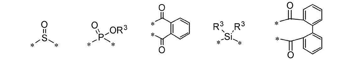
ただし、*は、それぞれ独立に、一般式(1)中の酸素原子との結合部位を表す。R3は、それぞれ独立に、炭素数1から3のアルキル基または炭素数6から10のアリール基を表す。

一般式(2)中、R2は以下に示す置換基のいずれかを表し、2つのR2は互いに同じでも異なっていてもよい。

ただし、*は、それぞれ独立に、一般式(2)中の酸素原子との結合部位を表す。Y1は、それぞれ独立に、単結合、-O-、-C(=O)O-、-OC(=O)-、または、-OC(=O)O-を表す。Sp1は、それぞれ独立に、単結合または炭素数1から8のアルキレン基を表す。Z1は、それぞれ独立に、水素原子または(メタ)アクリル基を表す。nは1以上の整数を表す。 The left-turning chiral agent is selected from the group consisting of a compound represented by the general formula (1) and a compound represented by the general formula (2). A composition kit according to 1.
In general formula (1), M represents a hydrogen atom or a substituent each independently. R 1 represents any of the following linking groups.
However, * represents the coupling | bond part with the oxygen atom in General formula (1) each independently. R 3 each independently represents an alkyl group having 1 to 3 carbon atoms or an aryl group having 6 to 10 carbon atoms.
In the general formula (2), R 2 represents any of the following substituents, and the two R 2 may be the same or different from each other.
However, * represents the coupling | bond part with the oxygen atom in General formula (2) each independently. Y 1 each independently represents a single bond, —O—, —C (═O) O—, —OC (═O) —, or —OC (═O) O—. Sp 1 independently represents a single bond or an alkylene group having 1 to 8 carbon atoms. Z < 1 > represents a hydrogen atom or a (meth) acryl group each independently. n represents an integer of 1 or more. - 前記左旋回性のキラル剤が、一般式(3)で表される化合物、および、一般式(4)で表される化合物からなる群から選択される、請求項1~4のいずれか1項に記載の組成物キット。

一般式(3)中、Raは以下に示す連結基のいずれかを表す。

ただし、*は、一般式(3)中の酸素原子との結合部位を表す。

一般式(4)中、Rbは以下に示す置換基を表し、2つのRbは互いに同じでも異なっていてもよい。

ただし、*は、一般式(4)中の酸素原子との結合部位を表す。Y2は、単結合、-O-、または、-OC(=O)-を表す。Sp2は、単結合または炭素数1から8のアルキレン基を表す。Z2は、水素原子または(メタ)アクリル基を表す。 The left-turning chiral agent is selected from the group consisting of a compound represented by the general formula (3) and a compound represented by the general formula (4). A composition kit according to 1.
In General Formula (3), R a represents one of the following linking groups.
However, * represents the coupling | bond part with the oxygen atom in General formula (3).
In General Formula (4), R b represents a substituent shown below, and two R b may be the same or different from each other.
However, * represents the coupling | bond part with the oxygen atom in General formula (4). Y 2 represents a single bond, —O—, or —OC (═O) —. Sp 2 represents a single bond or an alkylene group having 1 to 8 carbon atoms. Z 2 represents a hydrogen atom or a (meth) acryl group. - 前記色材が顔料である、請求項1~5のいずれか1項に記載の組成物キット。 The composition kit according to any one of claims 1 to 5, wherein the coloring material is a pigment.
- 前記重合性基を有する液晶化合物の30℃における屈折率異方性Δnが0.25以上である、請求項1~6のいずれか1項に記載の組成物キット。 The composition kit according to any one of claims 1 to 6, wherein the liquid crystal compound having a polymerizable group has a refractive index anisotropy Δn at 30 ° C of 0.25 or more.
- 前記重合性基を有する液晶化合物が、一般式(5)で表される化合物である、請求項1~7のいずれか1項に記載の組成物キット。

一般式(5)中、A1~A4は、それぞれ独立に、置換基を有していてもよい芳香族炭素環または複素環を表す。X1およびX2は、それぞれ独立に、単結合、-COO-、-OCO-、-CH2CH2-、-OCH2-、-CH2O-、-CH=CH-、-CH=CH-COO-、-OCO-CH=CH-、または、-C≡C-を表す。Y1およびY2は、それぞれ独立に、単結合、-O-、-S-、-CO-、-COO-、-OCO-、-CONH-、-NHCO-、-CH=CH-、-CH=CH-COO-、-OCO-CH=CH-、または、-C≡C-を表す。Sp1およびSp2は、それぞれ独立に、単結合、または、炭素数1~25の炭素鎖を表す。P1およびP2は、それぞれ独立に、水素原子または重合性基を表し、P1およびP2の少なくとも一方は重合性基を表す。n1およびn2はそれぞれ独立に0~2の整数を表し、n1またはn2が2の場合、複数あるA1、A2、X1およびX2は同じでもあっても異なっていてもよい。 The composition kit according to any one of claims 1 to 7, wherein the liquid crystal compound having a polymerizable group is a compound represented by the general formula (5).
In the general formula (5), A 1 to A 4 each independently represents an aromatic carbocycle or heterocycle which may have a substituent. X 1 and X 2 are each independently a single bond, —COO—, —OCO—, —CH 2 CH 2 —, —OCH 2 —, —CH 2 O—, —CH═CH—, —CH═CH —COO—, —OCO—CH═CH—, or —C≡C— is represented. Y 1 and Y 2 are each independently a single bond, —O—, —S—, —CO—, —COO—, —OCO—, —CONH—, —NHCO—, —CH═CH—, —CH = CH-COO-, -OCO-CH = CH-, or -C≡C-. Sp 1 and Sp 2 each independently represents a single bond or a carbon chain having 1 to 25 carbon atoms. P 1 and P 2 each independently represent a hydrogen atom or a polymerizable group, and at least one of P 1 and P 2 represents a polymerizable group. n 1 and n 2 each independently represents an integer of 0 to 2, and when n 1 or n 2 is 2, a plurality of A 1 , A 2 , X 1 and X 2 may be the same or different. Good. - 前記第1組成物、および、前記第2組成物が、それぞれ、光重合開始剤をさらに含む、請求項1~8のいずれか1項に記載の組成物キット。 The composition kit according to any one of claims 1 to 8, wherein each of the first composition and the second composition further contains a photopolymerization initiator.
- 前記第1組成物、および、前記第2組成物が、それぞれ、含フッ素化合物をさらに含む、請求項1~9のいずれか1項に記載の組成物キット。 The composition kit according to any one of claims 1 to 9, wherein each of the first composition and the second composition further contains a fluorine-containing compound.
- 波長730nmの吸光度に対する波長830nmの吸光度の比が3以上であるバンドパスフィルターを形成するために用いられる、請求項1~10のいずれか1項に記載の組成物キット。 The composition kit according to any one of claims 1 to 10, which is used for forming a band-pass filter having a ratio of absorbance at a wavelength of 830 nm to absorbance at a wavelength of 730 nm of 3 or more.
- 波長730nmの吸光度に対する波長630nmの吸光度の比が3以上であるバンドパスフィルターを形成するために用いられる、請求項11に記載の組成物キット。 The composition kit according to claim 11, which is used for forming a band-pass filter having a ratio of absorbance at a wavelength of 630 nm to absorbance at a wavelength of 730 nm of 3 or more.
- 波長850nmの吸光度に対する波長950nmの吸光度の比が3以上であるバンドパスフィルターを形成するために用いられる、請求項1~10のいずれか1項に記載の組成物キット。 The composition kit according to any one of claims 1 to 10, which is used for forming a band-pass filter having a ratio of absorbance at a wavelength of 950 nm to absorbance at a wavelength of 850 nm of 3 or more.
- 波長850nmの吸光度に対する波長750nmの吸光度の比が3以上であるバンドパスフィルターを形成するために用いられる、請求項13に記載の組成物キット。 The composition kit according to claim 13, which is used for forming a band-pass filter having a ratio of absorbance at a wavelength of 750 nm to absorbance at a wavelength of 850 nm of 3 or more.
- 波長940nmの吸光度に対する波長1040nmの吸光度の比が3以上であるバンドパスフィルターを形成するために用いられる、請求項1~10のいずれか1項に記載の組成物キット。 The composition kit according to any one of claims 1 to 10, which is used for forming a band-pass filter having a ratio of absorbance at a wavelength of 1040 nm to absorbance at a wavelength of 940 nm of 3 or more.
- 波長940nmの吸光度に対する波長840nmの吸光度の比が3以上であるバンドパスフィルターを形成するために用いられる、請求項15に記載の組成物キット。 The composition kit according to claim 15, which is used for forming a bandpass filter having a ratio of absorbance at a wavelength of 840 nm to absorbance at a wavelength of 940 nm of 3 or more.
- 請求項1~10のいずれか1項に記載の組成物キットを用いた積層体の製造方法であって、
前記第1組成物を用いて、右旋回性のコレステリック液晶相を固定化してなる光反射層Xaを形成する工程と、
前記第2組成物を用いて、左旋回性のコレステリック液晶相を固定化してなる光反射層Xbを形成する工程と、
前記第3組成物を用いて、光吸収層を形成する工程と、を含む積層体の製造方法。 A method for producing a laminate using the composition kit according to any one of claims 1 to 10,
Forming a light reflection layer Xa formed by fixing a right-turning cholesteric liquid crystal phase using the first composition;
Using the second composition to form a light reflection layer Xb formed by fixing a left-turning cholesteric liquid crystal phase;
Forming a light absorption layer using the third composition. - 互いに隣接して配置される複数の光反射層からなる反射積層膜、および、光吸収層を有し、
前記反射積層膜は、右旋回性のコレステリック液晶相を固定化してなる光反射層Xaを少なくとも1層と、左旋回性のコレステリック液晶相を固定化してなる光反射層Xbを少なくとも1層とを含み、
前記光反射層Xaの少なくとも1層の選択反射波長と前記光反射層Xbの少なくとも1層の選択反射波長とが等しく、
前記光吸収層は、色材を含む、積層体。 A reflective laminated film composed of a plurality of light reflecting layers disposed adjacent to each other, and a light absorbing layer;
The reflective laminated film includes at least one light reflecting layer Xa formed by fixing a right-turning cholesteric liquid crystal phase and at least one light reflecting layer Xb formed by fixing a left-turning cholesteric liquid crystal phase. Including
The selective reflection wavelength of at least one layer of the light reflection layer Xa is equal to the selective reflection wavelength of at least one layer of the light reflection layer Xb,
The said light absorption layer is a laminated body containing a coloring material. - 前記光反射層Xaに、螺旋捩れ力が30μm-1以上である右旋回性のキラル剤が含まれ、
前記光反射層Xbに、螺旋捩れ力が30μm-1以上である左旋回性のキラル剤が含まれる、請求項18に記載の積層体。 The light reflecting layer Xa includes a right-turning chiral agent having a helical twisting force of 30 μm −1 or more,
The laminate according to claim 18, wherein the light reflecting layer Xb contains a left-turning chiral agent having a helical twisting force of 30 µm -1 or more. - 前記左旋回性のキラル剤が、一般式(1)で表される化合物、および、一般式(2)で表される化合物からなる群から選択される、請求項18または19に記載の積層体。

一般式(1)中、Mは、それぞれ独立に、水素原子または置換基を表す。R1は以下に示す連結基のいずれかを表す。

ただし、*は、それぞれ独立に、一般式(1)中の酸素原子との結合部位を表す。R3は、それぞれ独立に、炭素数1から3のアルキル基または炭素数6から10のアリール基を表す。

一般式(2)中、R2は以下に示す置換基のいずれかを表し、2つのR2は互いに同じでも異なっていてもよい。

ただし、*は、それぞれ独立に、一般式(2)中の酸素原子との結合部位を表す。Y1は、それぞれ独立に、単結合、-O-、-C(=O)O-、-OC(=O)-、または、-OC(=O)O-を表す。Sp1は、それぞれ独立に、単結合または炭素数1から8のアルキレン基を表す。Z1は、それぞれ独立に、水素原子または(メタ)アクリル基を表す。nは1以上の整数を表す。 The laminate according to claim 18 or 19, wherein the left-turning chiral agent is selected from the group consisting of a compound represented by the general formula (1) and a compound represented by the general formula (2). .
In general formula (1), M represents a hydrogen atom or a substituent each independently. R 1 represents any of the following linking groups.
However, * represents the coupling | bond part with the oxygen atom in General formula (1) each independently. R 3 each independently represents an alkyl group having 1 to 3 carbon atoms or an aryl group having 6 to 10 carbon atoms.
In the general formula (2), R 2 represents any of the following substituents, and the two R 2 may be the same or different from each other.
However, * represents the coupling | bond part with the oxygen atom in General formula (2) each independently. Y 1 each independently represents a single bond, —O—, —C (═O) O—, —OC (═O) —, or —OC (═O) O—. Sp 1 independently represents a single bond or an alkylene group having 1 to 8 carbon atoms. Z < 1 > represents a hydrogen atom or a (meth) acryl group each independently. n represents an integer of 1 or more. - 前記左旋回性のキラル剤が、一般式(3)で表される化合物、および、一般式(4)で表される化合物からなる群から選択される、請求項18~20のいずれか1項に記載の積層体。
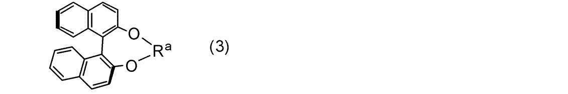
一般式(3)中、Raは以下に示す連結基のいずれかを表す。

ただし、*は、一般式(3)中の酸素原子との結合部位を表す。

一般式(4)中、Rbは以下に示す置換基を表し、2つのRbは互いに同じでも異なっていてもよい。

ただし、*は、一般式(4)中の酸素原子との結合部位を表す。Y2は、単結合、-O-、または、-OC(=O)-を表す。Sp2は、単結合または炭素数1から8のアルキレン基を表す。Z2は、水素原子または(メタ)アクリル基を表す。 The left-turning chiral agent is selected from the group consisting of a compound represented by the general formula (3) and a compound represented by the general formula (4). The laminated body as described in.
In General Formula (3), R a represents one of the following linking groups.
However, * represents the coupling | bond part with the oxygen atom in General formula (3).
In General Formula (4), R b represents a substituent shown below, and two R b may be the same or different from each other.
However, * represents the coupling | bond part with the oxygen atom in General formula (4). Y 2 represents a single bond, —O—, or —OC (═O) —. Sp 2 represents a single bond or an alkylene group having 1 to 8 carbon atoms. Z 2 represents a hydrogen atom or a (meth) acryl group. - 前記色材が顔料を含む、請求項18~21のいずれか1項に記載の積層体。 The laminate according to any one of claims 18 to 21, wherein the coloring material contains a pigment.
- 前記光反射層Xaおよび前記光反射層Xbのうち少なくとも一方を2層以上有し、
前記光反射層Xaが複数ある場合、それぞれの前記光反射層Xaに含まれる前記キラル剤の種類が同一であり、
前記光反射層Xbが複数ある場合、それぞれの前記光反射層Xbに含まれる前記キラル剤の種類が同一である、請求項18~22のいずれか1項に記載の積層体。 Two or more layers of at least one of the light reflecting layer Xa and the light reflecting layer Xb,
When there are a plurality of the light reflection layers Xa, the kind of the chiral agent contained in each of the light reflection layers Xa is the same,
The laminate according to any one of claims 18 to 22, wherein when there are a plurality of the light reflection layers Xb, the types of the chiral agents contained in the light reflection layers Xb are the same. - 前記反射積層膜のヘイズが1%以下である、請求項18~23のいずれか1項に記載の積層体。 The laminate according to any one of claims 18 to 23, wherein the reflective laminated film has a haze of 1% or less.
- 波長730nmの吸光度に対する波長830nmの吸光度の比が3以上である、請求項18~24のいずれか1項に記載の積層体。 The laminate according to any one of claims 18 to 24, wherein a ratio of absorbance at a wavelength of 830 nm to absorbance at a wavelength of 730 nm is 3 or more.
- 波長730nmの吸光度に対する波長630nmの吸光度の比が3以上である、請求項25に記載の積層体。 The laminate according to claim 25, wherein the ratio of the absorbance at a wavelength of 630 nm to the absorbance at a wavelength of 730 nm is 3 or more.
- 波長850nmの吸光度に対する波長950nmの吸光度の比が3以上である、請求項18~24のいずれか1項に記載の積層体。 The laminate according to any one of claims 18 to 24, wherein the ratio of the absorbance at a wavelength of 950 nm to the absorbance at a wavelength of 850 nm is 3 or more.
- 波長850nmの吸光度に対する波長750nmの吸光度の比が3以上である、請求項27に記載の積層体。 The laminate according to claim 27, wherein the ratio of the absorbance at a wavelength of 750 nm to the absorbance at a wavelength of 850 nm is 3 or more.
- 波長940nmの吸光度に対する波長1040nmの吸光度の比が3以上である、請求項18~24のいずれか1項に記載の積層体。 The laminate according to any one of claims 18 to 24, wherein a ratio of absorbance at a wavelength of 1040 nm to absorbance at a wavelength of 940 nm is 3 or more.
- 波長940nmの吸光度に対する波長840nmの吸光度の比が3以上である、請求項29に記載の積層体。 The laminate according to claim 29, wherein a ratio of absorbance at a wavelength of 840 nm to absorbance at a wavelength of 940 nm is 3 or more.
- 請求項18~30のいずれか1項に記載の積層体を有するバンドパスフィルター。
A band-pass filter having the laminate according to any one of claims 18 to 30.
Priority Applications (4)
| Application Number | Priority Date | Filing Date | Title |
|---|---|---|---|
| JP2017505380A JP6427659B2 (en) | 2015-03-10 | 2016-03-09 | Composition kit, laminate and method for producing the same, band pass filter |
| EP16761791.9A EP3270196B1 (en) | 2015-03-10 | 2016-03-09 | Method for manufacturing a bandpass filter |
| KR1020177025124A KR20170115600A (en) | 2015-03-10 | 2016-03-09 | Composition kit, laminate and manufacturing method thereof, band-pass filter |
| US15/680,311 US20180030161A1 (en) | 2015-03-10 | 2017-08-18 | Composition kit, laminate and method for producing same, and bandpass filter |
Applications Claiming Priority (4)
| Application Number | Priority Date | Filing Date | Title |
|---|---|---|---|
| JP2015-047431 | 2015-03-10 | ||
| JP2015047431 | 2015-03-10 | ||
| JP2016044269 | 2016-03-08 | ||
| JP2016-044269 | 2016-03-08 |
Related Child Applications (1)
| Application Number | Title | Priority Date | Filing Date |
|---|---|---|---|
| US15/680,311 Continuation US20180030161A1 (en) | 2015-03-10 | 2017-08-18 | Composition kit, laminate and method for producing same, and bandpass filter |
Publications (1)
| Publication Number | Publication Date |
|---|---|
| WO2016143824A1 true WO2016143824A1 (en) | 2016-09-15 |
Family
ID=56880538
Family Applications (1)
| Application Number | Title | Priority Date | Filing Date |
|---|---|---|---|
| PCT/JP2016/057391 WO2016143824A1 (en) | 2015-03-10 | 2016-03-09 | Composition kit, layered body and method for manufacturing same, and bandpass filter |
Country Status (6)
| Country | Link |
|---|---|
| US (1) | US20180030161A1 (en) |
| EP (1) | EP3270196B1 (en) |
| JP (1) | JP6427659B2 (en) |
| KR (1) | KR20170115600A (en) |
| TW (1) | TWI697545B (en) |
| WO (1) | WO2016143824A1 (en) |
Cited By (6)
| Publication number | Priority date | Publication date | Assignee | Title |
|---|---|---|---|---|
| WO2017056909A1 (en) * | 2015-09-30 | 2017-04-06 | 富士フイルム株式会社 | Laminate body, optical sensor, and kit |
| WO2018021485A1 (en) * | 2016-07-28 | 2018-02-01 | 富士フイルム株式会社 | Blue light blocking film and light source |
| JP2018169579A (en) * | 2017-03-30 | 2018-11-01 | 住友ベークライト株式会社 | Optical layer |
| WO2020202876A1 (en) * | 2019-03-29 | 2020-10-08 | ソニーセミコンダクタソリューションズ株式会社 | Solid-state imaging element and imaging device |
| EP3633737A4 (en) * | 2017-05-23 | 2021-03-03 | AGC Inc. | Cover glass for solar cells and solar cell module |
| US11820932B2 (en) * | 2016-09-28 | 2023-11-21 | Merck Patent Gmbh | Polymerisable liquid crystal material and polymerised liquid crystal film |
Families Citing this family (3)
| Publication number | Priority date | Publication date | Assignee | Title |
|---|---|---|---|---|
| KR102443408B1 (en) * | 2016-05-17 | 2022-09-15 | 메르크 파텐트 게엠베하 | Polymeric liquid crystal material and polymerized liquid crystal film |
| CN109912560B (en) * | 2018-12-14 | 2021-03-23 | 陕西师范大学 | Fluorescent material with aggregation-induced emission effect and circular polarization and preparation method thereof |
| WO2020175185A1 (en) * | 2019-02-28 | 2020-09-03 | 富士フイルム株式会社 | Compound, liquid crystal composition, cured product, optically anisotropic body, and reflective film |
Citations (7)
| Publication number | Priority date | Publication date | Assignee | Title |
|---|---|---|---|---|
| JPH10239684A (en) * | 1996-06-20 | 1998-09-11 | Seiko Instr Inc | Reflection-type liquid crystal display device |
| JP2002080478A (en) * | 2000-06-27 | 2002-03-19 | Fuji Photo Film Co Ltd | Photoreactive optically active compound, photoreactive chiral agent, liquid crystal composition, liquid crystal color filter, optical film, recording medium, and method for changing twist structure of liquid crystal |
| JP2002302487A (en) * | 2000-12-14 | 2002-10-18 | Fuji Photo Film Co Ltd | Optically active compound, photoreaction type chiral agent, liquid crystal composition, method for changing spiral structure of liquid crystal, method for fixing spiral structure of liquid crystal, liquid crystal color filter, optical filter and recording medium |
| JP2012137728A (en) * | 2010-12-10 | 2012-07-19 | Asahi Glass Co Ltd | Infrared transmission filter and imaging apparatus using the same |
| JP2014059437A (en) * | 2012-09-18 | 2014-04-03 | Fujifilm Corp | Heat-ray shielding film, manufacturing method therefor, laminated glass, and heat-ray shielding member |
| JP2014071356A (en) * | 2012-09-28 | 2014-04-21 | Fujifilm Corp | Infrared cut film, infrared cut laminated glass, and infrared cut member |
| WO2014097895A1 (en) * | 2012-12-17 | 2014-06-26 | 富士フイルム株式会社 | Multilayered cholesteric liquid crystal, process for producing same, and laminate of multilayered cholesteric liquid crystal |
Family Cites Families (5)
| Publication number | Priority date | Publication date | Assignee | Title |
|---|---|---|---|---|
| US6514578B1 (en) * | 1999-06-30 | 2003-02-04 | Merck Patent Gesellschaft Mit Beschrankter Haftung | Polymerizable mesogenic tolanes |
| JP5153761B2 (en) * | 2009-12-24 | 2013-02-27 | 日東電工株式会社 | Method for producing broadband cholesteric liquid crystal film |
| CN104823082B (en) * | 2012-11-29 | 2017-07-28 | 富士胶片株式会社 | Composition, infrared ray pass through optical filter and its manufacture method, infrared ray sensor and dyed layer |
| JP6317432B2 (en) * | 2014-05-01 | 2018-04-25 | 富士フイルム株式会社 | Coloring composition, film, color filter, pattern forming method, color filter manufacturing method, solid-state imaging device, and infrared sensor |
| WO2015198784A1 (en) * | 2014-06-25 | 2015-12-30 | 富士フイルム株式会社 | Laminate, infrared absorption filter, band pass filter, method for manufacturing laminate, kit for forming band pass filter, and image display device |
-
2016
- 2016-03-09 WO PCT/JP2016/057391 patent/WO2016143824A1/en active Application Filing
- 2016-03-09 JP JP2017505380A patent/JP6427659B2/en active Active
- 2016-03-09 EP EP16761791.9A patent/EP3270196B1/en active Active
- 2016-03-09 TW TW105107166A patent/TWI697545B/en active
- 2016-03-09 KR KR1020177025124A patent/KR20170115600A/en not_active Application Discontinuation
-
2017
- 2017-08-18 US US15/680,311 patent/US20180030161A1/en not_active Abandoned
Patent Citations (7)
| Publication number | Priority date | Publication date | Assignee | Title |
|---|---|---|---|---|
| JPH10239684A (en) * | 1996-06-20 | 1998-09-11 | Seiko Instr Inc | Reflection-type liquid crystal display device |
| JP2002080478A (en) * | 2000-06-27 | 2002-03-19 | Fuji Photo Film Co Ltd | Photoreactive optically active compound, photoreactive chiral agent, liquid crystal composition, liquid crystal color filter, optical film, recording medium, and method for changing twist structure of liquid crystal |
| JP2002302487A (en) * | 2000-12-14 | 2002-10-18 | Fuji Photo Film Co Ltd | Optically active compound, photoreaction type chiral agent, liquid crystal composition, method for changing spiral structure of liquid crystal, method for fixing spiral structure of liquid crystal, liquid crystal color filter, optical filter and recording medium |
| JP2012137728A (en) * | 2010-12-10 | 2012-07-19 | Asahi Glass Co Ltd | Infrared transmission filter and imaging apparatus using the same |
| JP2014059437A (en) * | 2012-09-18 | 2014-04-03 | Fujifilm Corp | Heat-ray shielding film, manufacturing method therefor, laminated glass, and heat-ray shielding member |
| JP2014071356A (en) * | 2012-09-28 | 2014-04-21 | Fujifilm Corp | Infrared cut film, infrared cut laminated glass, and infrared cut member |
| WO2014097895A1 (en) * | 2012-12-17 | 2014-06-26 | 富士フイルム株式会社 | Multilayered cholesteric liquid crystal, process for producing same, and laminate of multilayered cholesteric liquid crystal |
Non-Patent Citations (1)
| Title |
|---|
| See also references of EP3270196A4 * |
Cited By (9)
| Publication number | Priority date | Publication date | Assignee | Title |
|---|---|---|---|---|
| WO2017056909A1 (en) * | 2015-09-30 | 2017-04-06 | 富士フイルム株式会社 | Laminate body, optical sensor, and kit |
| WO2018021485A1 (en) * | 2016-07-28 | 2018-02-01 | 富士フイルム株式会社 | Blue light blocking film and light source |
| JPWO2018021485A1 (en) * | 2016-07-28 | 2019-05-23 | 富士フイルム株式会社 | Blue light cut film and light source |
| US10714665B2 (en) | 2016-07-28 | 2020-07-14 | Fujifilm Corporation | Blue light blocking and light source |
| US11820932B2 (en) * | 2016-09-28 | 2023-11-21 | Merck Patent Gmbh | Polymerisable liquid crystal material and polymerised liquid crystal film |
| JP2018169579A (en) * | 2017-03-30 | 2018-11-01 | 住友ベークライト株式会社 | Optical layer |
| EP3633737A4 (en) * | 2017-05-23 | 2021-03-03 | AGC Inc. | Cover glass for solar cells and solar cell module |
| US11616155B2 (en) | 2017-05-23 | 2023-03-28 | AGC Inc. | Cover glass for solar cell module and solar cell module |
| WO2020202876A1 (en) * | 2019-03-29 | 2020-10-08 | ソニーセミコンダクタソリューションズ株式会社 | Solid-state imaging element and imaging device |
Also Published As
| Publication number | Publication date |
|---|---|
| TWI697545B (en) | 2020-07-01 |
| JP6427659B2 (en) | 2018-11-21 |
| EP3270196B1 (en) | 2019-11-13 |
| EP3270196A4 (en) | 2018-03-28 |
| US20180030161A1 (en) | 2018-02-01 |
| EP3270196A1 (en) | 2018-01-17 |
| TW201638306A (en) | 2016-11-01 |
| KR20170115600A (en) | 2017-10-17 |
| JPWO2016143824A1 (en) | 2017-12-28 |
Similar Documents
| Publication | Publication Date | Title |
|---|---|---|
| JP6427659B2 (en) | Composition kit, laminate and method for producing the same, band pass filter | |
| JP6960481B2 (en) | Polymerizable liquid crystal composition and optical film | |
| JP6606555B2 (en) | Laminate, optical sensor, and kit | |
| KR102111538B1 (en) | Polymerizable compound, polymerizable composition, polymer, and optical anistropic body | |
| JP6872366B2 (en) | Phase difference film | |
| WO2018003642A1 (en) | Color filter for image sensor, image sensor, and method of manufacturing color filter for image sensor | |
| KR102026551B1 (en) | Laminated body, solid-state image sensor, manufacturing method of a laminated body, kit | |
| WO2014050583A1 (en) | Infrared-blocking film, infrared-blocking laminated glass, and infrared-blocking member | |
| US20200174171A1 (en) | Optically anisotropic film, circularly polarizing plate, and display device | |
| WO2019013092A1 (en) | Elliptically polarizing plate | |
| JP2022008866A (en) | Patterned polarizing film | |
| WO2019189809A1 (en) | Optical element and light guide element | |
| WO2018042924A1 (en) | Color filter for image sensor, image sensor, and method for manufacturing color filter for image sensor | |
| KR20170108084A (en) | Laminate and optical film | |
| CN110809585B (en) | Composition, film, infrared transmission filter, solid-state imaging element, image display device, and infrared sensor | |
| JP2017181705A (en) | Composition, film, optical filter, laminate, solid state image sensor, image display device, and infrared sensor | |
| US20200115482A1 (en) | Mixture, polymer, optical film, optically anisotropic product, polarizing plate, display device, antireflection film, and production method for mixture | |
| CN111684327B (en) | Vertical alignment liquid crystal cured film | |
| WO2023282261A1 (en) | Laminate, sight line tracking system, and head-mounted display | |
| CN115917379A (en) | Polarizing plate and method for producing same | |
| JP7130789B2 (en) | optical laminate | |
| JP2018170212A (en) | Method for manufacturing organic EL image display device | |
| WO2022196632A1 (en) | Optical laminated body | |
| WO2019221123A1 (en) | Method for manufacturing optical laminate and method for manufacturing display device |
Legal Events
| Date | Code | Title | Description |
|---|---|---|---|
| 121 | Ep: the epo has been informed by wipo that ep was designated in this application |
Ref document number: 16761791 Country of ref document: EP Kind code of ref document: A1 |
|
| DPE1 | Request for preliminary examination filed after expiration of 19th month from priority date (pct application filed from 20040101) | ||
| REEP | Request for entry into the european phase |
Ref document number: 2016761791 Country of ref document: EP |
|
| ENP | Entry into the national phase |
Ref document number: 20177025124 Country of ref document: KR Kind code of ref document: A |
|
| ENP | Entry into the national phase |
Ref document number: 2017505380 Country of ref document: JP Kind code of ref document: A |
|
| NENP | Non-entry into the national phase |
Ref country code: DE |