WO2016143175A1 - 照射制御装置、中性子線照射装置、これに用いる中性子チョッパ、中性子線照射制御方法 - Google Patents
照射制御装置、中性子線照射装置、これに用いる中性子チョッパ、中性子線照射制御方法 Download PDFInfo
- Publication number
- WO2016143175A1 WO2016143175A1 PCT/JP2015/077005 JP2015077005W WO2016143175A1 WO 2016143175 A1 WO2016143175 A1 WO 2016143175A1 JP 2015077005 W JP2015077005 W JP 2015077005W WO 2016143175 A1 WO2016143175 A1 WO 2016143175A1
- Authority
- WO
- WIPO (PCT)
- Prior art keywords
- neutron
- slit
- neutron beam
- chopper
- irradiation
- Prior art date
- Legal status (The legal status is an assumption and is not a legal conclusion. Google has not performed a legal analysis and makes no representation as to the accuracy of the status listed.)
- Ceased
Links
Images





Classifications
-
- G—PHYSICS
- G21—NUCLEAR PHYSICS; NUCLEAR ENGINEERING
- G21K—HANDLING OF PARTICLES OR IONISING RADIATION NOT OTHERWISE PROVIDED FOR; IRRADIATION DEVICES; GAMMA RAY OR X-RAY MICROSCOPES
- G21K1/00—Arrangements for handling particles or ionising radiation, e.g. focusing or moderating
- G21K1/02—Arrangements for handling particles or ionising radiation, e.g. focusing or moderating using diaphragms, collimators
- G21K1/04—Arrangements for handling particles or ionising radiation, e.g. focusing or moderating using diaphragms, collimators using variable diaphragms, shutters, choppers
-
- G—PHYSICS
- G21—NUCLEAR PHYSICS; NUCLEAR ENGINEERING
- G21K—HANDLING OF PARTICLES OR IONISING RADIATION NOT OTHERWISE PROVIDED FOR; IRRADIATION DEVICES; GAMMA RAY OR X-RAY MICROSCOPES
- G21K5/00—Irradiation devices
- G21K5/02—Irradiation devices having no beam-forming means
-
- H—ELECTRICITY
- H05—ELECTRIC TECHNIQUES NOT OTHERWISE PROVIDED FOR
- H05H—PLASMA TECHNIQUE; PRODUCTION OF ACCELERATED ELECTRICALLY-CHARGED PARTICLES OR OF NEUTRONS; PRODUCTION OR ACCELERATION OF NEUTRAL MOLECULAR OR ATOMIC BEAMS
- H05H3/00—Production or acceleration of neutral particle beams, e.g. molecular or atomic beams
- H05H3/06—Generating neutron beams
-
- H—ELECTRICITY
- H05—ELECTRIC TECHNIQUES NOT OTHERWISE PROVIDED FOR
- H05H—PLASMA TECHNIQUE; PRODUCTION OF ACCELERATED ELECTRICALLY-CHARGED PARTICLES OR OF NEUTRONS; PRODUCTION OR ACCELERATION OF NEUTRAL MOLECULAR OR ATOMIC BEAMS
- H05H6/00—Targets for producing nuclear reactions
-
- H—ELECTRICITY
- H05—ELECTRIC TECHNIQUES NOT OTHERWISE PROVIDED FOR
- H05H—PLASMA TECHNIQUE; PRODUCTION OF ACCELERATED ELECTRICALLY-CHARGED PARTICLES OR OF NEUTRONS; PRODUCTION OR ACCELERATION OF NEUTRAL MOLECULAR OR ATOMIC BEAMS
- H05H9/00—Linear accelerators
Definitions
- the present invention relates to an irradiation control device, a neutron beam irradiation device, a neutron chopper used therefor, and a neutron beam irradiation control method.
- the neutron beam irradiation device is an acceleration device that accelerates charged particles and emits charged particle beams, a target that generates neutron beams by irradiation of charged particle beams emitted from the acceleration device, and a neutron beam generated by the target is decelerated. And a speed reducer.
- a neutron beam irradiation apparatus is used in an apparatus that measures the internal state of an irradiated object. Specifically, a neutron beam is irradiated to the irradiated object by a neutron beam irradiation apparatus, and a neutron beam transmitted through the irradiated object is detected using a neutron detector, thereby obtaining a transmission image of the irradiated object.
- the neutron beam irradiation device as a device for selecting the timing or speed of the neutron beam that irradiates the irradiated object or the neutron beam that reaches the detector, the neutron beam is transmitted for a part of time, and the neutron beam for the remaining time.
- Some neutron beam irradiation apparatuses irradiate charged particle beams in a pulse form from an accelerator.
- Patent Document 1 describes an apparatus that synchronizes the timing of a charged particle beam generated from an acceleration device and the timing of movement of a slit of a neutron chopper by controlling the movement of the chopper.
- Patent Document 2 describes a neutron disk chopper that rotates a disk having a passing part that passes a neutron beam and a blocking part that includes a neutron absorber that blocks the neutron beam. Further, it is described that the neutron disc chopper is formed so that the disc thickness gradually decreases from the rotation center side toward the outer peripheral side.
- the apparatus described in Patent Document 1 requires a mechanism for controlling the rotation of the neutron chopper. Also, because the mechanical mechanism adjusts the movement of the chopper, specifically the rotation, there is a difference between the input control command and the actual operation due to air resistance, bearing friction resistance, deviation of the chopper structure, etc. May occur and rotation may become unstable, or there may be a limit to increasing the accuracy of control. Further, the neutron chopper described in Patent Document 2 has a distribution in the shielding performance of the neutron beam because the thickness is different between the outer peripheral portion and the inner peripheral portion of the disk.
- An object of the present invention is to provide an irradiation control device, a neutron beam irradiation device, a neutron chopper used for the irradiation control device, and a neutron beam irradiation control method capable of irradiating a set neutron beam with simple control.
- a charged particle beam to be converted into a neutron beam is irradiated in a pulsed manner, and the neutron beam is passed through an accelerator capable of adjusting the irradiation timing and a shielding unit that shields the neutron beam.
- a neutron irradiation apparatus for a neutron beam irradiation apparatus comprising: a neutron chopper having a rotating part formed with a slit and a driving part for rotating the rotating part; and a position detecting part for detecting the position of the slit of the neutron chopper.
- the irradiation control apparatus is characterized in that a pulse for irradiating the charged particle beam is generated.
- a charged particle beam to be converted into a neutron beam is irradiated in a pulsed manner and an irradiation device capable of adjusting irradiation timing, and the charged particle beam emitted from the acceleration device is irradiated.
- a plate-shaped disk in which a slit for passing a neutron beam is formed in a shielding unit that shields the neutron beam, and a direction in which the disk intersects a plane having the largest area of the disk.
- a neutron chopper characterized by having a drive unit that rotates as a shaft, and the slit has a width in the rotation direction that is wider as it is away from the rotation shaft and a constant angular width.
- a charged particle beam to be converted into a neutron beam is irradiated in a pulsed manner, and the neutron beam is allowed to pass through an accelerator capable of adjusting the irradiation timing and a shielding unit that shields the neutron beam.
- An irradiation control method for a neutron beam irradiation apparatus comprising: a neutron chopper having a rotating part formed with a slit and a driving part for rotating the rotating part; and a position detecting part for detecting a position of the slit of the neutron chopper.
- a neutron beam irradiation control method is provided that generates a pulse for commanding irradiation.
- the set neutron beam can be irradiated with simple control.
- FIG. 1 is a schematic diagram illustrating an example of a neutron transmission imaging apparatus having a neutron irradiation apparatus.
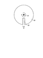
- FIG. 2 is a front view showing a schematic configuration of the neutron chopper.
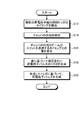
- FIG. 3 is a flowchart showing an example of the operation of the neutron beam irradiation apparatus.
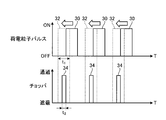
- FIG. 4 is an explanatory diagram for explaining an example of the operation of the neutron beam irradiation apparatus.
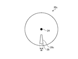
- FIG. 5 is a front view showing a schematic configuration of another example of the neutron chopper.
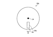
- FIG. 6 is a front view showing a schematic configuration of another example of the neutron chopper.
- FIG. 7 is a front view showing a schematic configuration of another example of the neutron chopper.
- FIG. 1 is a schematic diagram illustrating an example of a neutron transmission imaging apparatus having a neutron irradiation apparatus.
- FIG. 2 is a front view showing a schematic configuration of the neutron chopper.
- FIG. 3
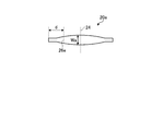
- FIG. 8 is a cross-sectional view showing a schematic configuration of another example of the neutron chopper.
- FIG. 9 is a cross-sectional view illustrating a schematic configuration of another example of the neutron chopper.
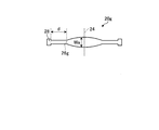
- FIG. 10 is a cross-sectional view showing a schematic configuration of another example of the neutron chopper.
- FIG. 11 is a cross-sectional view illustrating a schematic configuration of another example of the neutron chopper.
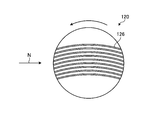
- FIG. 12 is a perspective view showing a schematic configuration of another example of the neutron chopper.
- FIG. 13 is a cross-sectional view illustrating a schematic configuration of another example of the neutron chopper.
- the neutron beam irradiation apparatus 1 is applied to an inspection apparatus that irradiates an inspection object such as a device or a structure with a neutron beam N and inspects the inside of the inspection object nondestructively. The case will be described.
- FIG. 1 is a schematic diagram showing an example of a neutron transmission imaging apparatus having a neutron beam irradiation apparatus.
- the neutron transmission imaging device 100 includes a neutron beam irradiation device 1, a detector 12, a position detection device 13, and a control device 14.
- the neutron beam irradiation apparatus 1 includes an acceleration device 2 that accelerates charged particles and emits a charged particle beam P, an adjustment device 3 that adjusts an irradiation state of the charged particle beam P emitted from the acceleration device 2, and a charged particle beam.
- a target 5 that generates a neutron beam N by irradiation of P
- a speed reducer 6 that decelerates the neutron beam N generated by the target 5
- a collimator 7 that parallelizes the neutron beam N emitted from the speed reducer 6, and a chopper ( Neutron chopper) 10.
- the irradiated object S is irradiated with the neutron beam N emitted from the collimator 7.
- the neutron beam irradiation apparatus 1 switches in a time division manner the state where the irradiated neutron beam N is shielded by the chopper 10 and the state where it is allowed to pass through.
- Accelerator 2 includes a circular accelerator or a linear accelerator.
- the acceleration device 2 accelerates charged particles (protons, electrons, or heavy particles), and generates and emits charged particle beams (proton beams, electron beams, or heavy particle beams) P.
- the acceleration device 2 can irradiate the charged particle beam P with a pulse and change the timing of the irradiation pulse.
- a linac accelerator can be used as the acceleration device 2.
- the adjustment device 3 includes a plurality of electromagnets, and adjusts the irradiation state of the charged particle beam P emitted from the acceleration device 2.
- the irradiation state of the charged particle beam P includes adjustment of the traveling direction of the charged particle beam P and shaping of the charged particle beam P.
- the adjusting device 3 suppresses the divergence of the charged particle beam P and focuses the charged particle beam P.
- the adjusting device 3 guides the charged particle beam P emitted from the acceleration device 2 to the scanning device 4.
- the neutron beam irradiation apparatus 1 includes a scanning device 4 that scans the charged particle beam P.
- the scanning device 4 scans the charged particle beam P and adjusts the irradiation position of the charged particle beam P with respect to the target 5.
- the scanning device 4 shapes the charged particle beam P irradiated to the target 5.
- the scanning device 4 may be omitted.
- the charged particle beam P emitted from the acceleration device 2 and passed through the adjustment device 3 and the scanning device 4 is irradiated onto the target 5.
- the target 5 generates a neutron beam N by irradiation with the charged particle beam P.
- the target 5 may be referred to as a neutron beam generating member 5.
- the target 5 includes a liquid or solid plate-like member formed of, for example, beryllium (Be), lithium (Li), or a compound containing them.
- the target 5 may be a circular or rectangular plate-shaped solid member, or heated liquid lithium. For example, liquid lithium that has been continuously flowed so as to have a constant thickness may be used as the target 5.
- Deceleration device 6 decelerates neutron beam N generated at target 5.
- the speed reducer 6 is disposed between the target 5 and the irradiated object S in the course of the neutron beam N.
- the target 5 generates high energy fast neutrons.
- the speed reducer 6 reduces the energy of fast neutrons and generates low-speed, low-energy neutrons (thermal neutrons, cold neutrons, or epithermal neutrons).
- the collimator 7 collimates the neutron beam N emitted from the speed reducer 6.
- the irradiated object S is irradiated with a neutron beam N that is collimated by the collimator 7 and emitted from the collimator 7.
- the chopper 10 is disposed between the collimator 7 and the irradiated object S in the present embodiment, the path through which the neutron beam N is irradiated.
- the chopper 10 has a rotating part having a shielding part that shields the neutron beam N, a passing part that allows the neutron beam N to pass through, and a driving part that rotates the rotating part, and moves the position of the passing part so that irradiation is performed.
- the state where the generated neutron beam N is shielded and the state where it is passed through are switched, and the state where the neutron beam N does not reach the irradiated body S and the state where it reaches the irradiated body S are switched.
- FIG. 2 is a front view showing a schematic configuration of the neutron chopper.
- the chopper 10 includes a disk 20 and a drive unit 22.
- the disk 20 is a disk-shaped plate made of a compound or mixture containing a material that shields the neutron beam N, for example, a neutron absorber such as lead or boron.
- the drive unit 22 rotates the disk 20 around the rotation shaft 24.
- the rotating shaft 24 is formed substantially at the center of the disk 20.
- the rotating shaft 24 is oriented in parallel to the irradiation direction of the neutron beam N.
- the disk 20 is formed with a slit 26 extending in the radial direction of the disk, that is, in a direction away from the rotating shaft 24.
- the slit 26 has a shape in which a straight line passing through the rotation shaft 24 is a center line.
- the width W of the surface of the disk 20, that is, the surface orthogonal to the rotation shaft 24 is constant.
- the part where the slit 26 is formed corresponds to a passing part that allows the neutron beam N to pass through, and the other part corresponds to a shielding part that shields the neutron beam N.
- the chopper 10 can rotate the position of the slit 26 by rotating the disk 20 by the drive unit 22. Thereby, depending on the position of the slit 26 in the rotation direction, the position where the neutron beam N passes and the state where the slit 26 overlaps and the state where the neutron beam N passes, the position where the neutron beam N passes, and the position where the slit 26 is not formed. The state of shielding the overlapping neutron beam N is switched.
- the diameter of the disk 20 is 50 mm or more and 1000 mm or less.
- the thickness of the disk 20 changes with materials to form, it has thickness required for shielding of the neutron beam N, for example, is 10 mm or more and 500 mm or less.
- the drive part 22 illustrates rotating the disk 20 at 10 Hz or more and 1000 Hz or less (10 rotations per second or more and 1000 rotations or less per second).
- the width W is preferably 0.5 mm or more and 100 mm or less.
- the slit 26 sets the angle range in a rotation direction to 0.05 degree or more and 10 degrees or less.
- the chopper 10 can set the width W of the slit 26 within the above range or the angular range in the rotation direction within the above range, thereby making it possible to set the time for the neutron beam N to pass within a predetermined range and increasing the measurement accuracy. Can do.
- the detector 12 is arranged in a direction in which the neutron beam N is irradiated from the neutron beam irradiation apparatus 1.
- the detector 12 is disposed at a position facing the neutron beam irradiation apparatus 1 with the irradiated object S interposed therebetween.
- a detection element for detecting the neutron beam N is arranged on the surface facing the neutron beam irradiation apparatus 1.
- the detector 12 detects the neutron beam N irradiated from the neutron beam irradiation apparatus 1 and having passed through the region where the irradiated object S is arranged with a detection element.
- the detection elements are arranged in a matrix on the surface of the detector 12.
- the detector 12 sends the detected result to the control device 14.
- the control device 14 controls the operation of each part of the neutron transmission imaging device 100.
- the control device 14 has an arithmetic processing function and a storage function.
- the control device 14 has a function of an irradiation control device that controls the irradiation operation of the neutron beam irradiation device 1.
- the control device 14 includes a phase detection unit 14a that implements the function of the irradiation control device, a comparison unit 14b, a trigger generation unit 14c, and a pulse generation unit 14d.
- the control apparatus 14 of this embodiment showed the case where each part was arrange
- the control device 14 includes the phase detection unit 14a and the comparison unit 14b as one device inside the position detection device 13, and the trigger generation unit 14c and the pulse generation unit 14d as one device inside the acceleration device 2. May be provided.
- the phase detection unit 14 a acquires the detection result of the position detection device 13 and detects the position of the slit 26 of the chopper 10. Based on the detected position of the slit 26 of the chopper 10, the phase detector 14 a detects the timing at which the neutron beam N irradiated from the acceleration device 2 and passed through the collimator 7 passes through the slit 26.
- the comparison unit 14b compares the timing at which the neutron beam detected from the position in the rotation direction of the slit 26 detected by the phase detection unit 14a with the timing at which the accelerator 2 generates the charged particle beam P. , To detect the difference between the two.
- the trigger generation unit 14 c Based on the detected difference, the trigger generation unit 14 c generates a trigger signal that serves as a trigger for generating a pulse that generates a charged particle beam in the acceleration device 2.
- the pulse generator 14d generates a pulse for generating a charged particle beam based on the trigger signal.
- the control device 14 generates a pulse for generating a charged particle beam, and sends the generated pulse to the acceleration device 2 to irradiate the charged particle beam from the acceleration device 2.
- FIG. 3 is a flowchart showing an example of the operation of the neutron beam irradiation apparatus.
- FIG. 4 is an explanatory diagram for explaining an example of the operation of the neutron beam irradiation apparatus.
- the operations in FIGS. 3 and 4 can be realized by executing the operations in each unit of the control device 14.
- the control device 14 detects the timing of the current charged particle beam irradiation trigger (timing to irradiate the charged particle beam) (step S12).
- the control device 14 may obtain information from the information stored therein or may obtain information from the acceleration device 2.
- the control device 14 detects the phase of the chopper 10 (step S14).
- the detection result of the position detection device 13 is acquired, the position of the slit 26 of the chopper 10 is detected, and the neutron beam N irradiated from the acceleration device 2 and passed through the collimator 7 based on the detected position of the slit 26 of the chopper 10. Detects the timing of passing through the slit 26.
- the control device 14 detects the difference between the phase of the chopper 10 and the timing at which the beam passes through the slit (step S16). That is, the timing at which the neutron beam detected from the position in the rotation direction of the slit 26 detected by the phase detector 14a passes through the slit 26 and the timing at which the accelerator 2 generates the charged particle beam P are compared, and both Detect the difference.
- the control device 14 generates a trigger signal serving as a trigger for generating a pulse for generating a charged particle beam in the acceleration device 2 based on the detected difference (step S18).
- the control device 14 generates a pulse for generating a charged particle beam based on the trigger signal (step S20).
- the control device 14 generates a pulse for generating a charged particle beam, and sends the generated pulse to the acceleration device 2 to irradiate the charged particle beam from the acceleration device 2.
- the pulse 30 for generating the initial charged particle beam and the pulse 34 indicating the timing at which the slit 26 of the chopper 10 is located in the region through which the neutron beam N passes are shifted. If so, the timing for generating the charged particle beam is corrected to the pulse 32 for generating the charged particle beam. As described above, the neutron beam irradiation apparatus 1 adjusts the generation timing of the charged particle pulse based on the phase of the slit of the chopper 10, so that the desired particle beam N passes through the slit 26 at the timing when the desired particle beam N passes through the slit 26. Can be generated by the acceleration device 2. In FIG.
- pulses 30 and 32, slits, and the same timing are used as a pulse for generating a charged particle beam and a time for a neutron beam emitted and converted to reach the disk 20 based on the charged particle pulse.
- pulse 34 indicating the timing of 26 in the region through which the neutron beam N passes is shown in an easy-to-understand manner, the relationship is not limited to this.
- the pulses 30 and 32 are times when a neutron beam emitted and converted based on the charged particle pulse reaches the disk 20, and the actual charged particle pulse may have another timing.
- the neutron beam irradiation apparatus 1 can perform synchronous control without controlling hardware, specifically, a rotating device, by controlling the timing of irradiating the charged particle beam from the acceleration device 2, with high accuracy. Synchronization control is possible. Specifically, since the chopper movement, specifically rotation, is adjusted by a mechanical mechanism, the input control command and the actual operation may be affected by air resistance, bearing friction resistance, chopper structure bias, etc. It is possible to prevent the rotation from becoming unstable due to a gap between them. Further, since synchronization can be performed by electrical timing control, the control device can be simplified.
- the neutron beam irradiation apparatus 1 can control the timing or speed of the neutron beam irradiating the irradiated object or the neutron beam reaching the detector with high accuracy by enabling highly accurate synchronous control. .
- the wavelength of the neutron beam that reaches the detector 12 or reaches the irradiated object S can be controlled with high accuracy, and a neutron beam whose energy is close to the peak is applied to the detector 12 or the irradiated object S. Can be reached.
- the neutron beam irradiation apparatus 1 can shorten the time to irradiate a charged particle beam by using a linac accelerator as the acceleration device 2 and irradiating the charged particle beam with a pulse whose timing can be adjusted. Efficiency can be increased. In addition, by shortening the time for irradiating the charged particle beam, the load on the member that shields the charged particle beam and the neutron beam can be reduced, and the energy of the charged particle beam at the time of irradiation can be increased.
- the neutron beam irradiation apparatus 1 irradiates charged particles having a time t1 (pulse width) of 0.01 ⁇ sec or more and 1000 ⁇ sec or less from the acceleration device 2, and sets the time t2 for the chopper 10 to pass the neutron beam. It is preferable that the time is 1 ⁇ s or more and 100 ⁇ s or less. Thereby, the irradiated neutron beam can be made into a shorter pulse neutron beam by the chopper 10. Thereby, measurement accuracy can be made higher.
- the charged particles irradiated for the time t ⁇ b> 1 by the acceleration device 2 become a neutron beam by the target 5, and then pass through the speed reduction device 6 so that the distribution of the neutron beam velocity is achieved. Arise.
- the time for the neutron beam to pass through the region where the chopper 10 is disposed is longer than the time t1 for irradiating the charged particles from the acceleration device 2, for example, 10 ⁇ s or more and 100 ⁇ s or less.
- the irradiated neutron beam is made a shorter pulse neutron beam by the chopper 10. Can do.
- the acceleration apparatus 2 is a proton beam accelerator, it is preferable to irradiate from the acceleration apparatus 2 the charged particle whose time t1 is 10 to 1000 microseconds.
- the chopper 10 is disposed between the collimator 7 and the irradiated object S in the passage path of the neutron beam N, but the present invention is not limited to this.
- a chopper 10 may be disposed between the speed reducer 6 and the collimator 7.
- the neutron chopper is not limited to the shape of the above embodiment.
- another example of the neutron chopper will be described with reference to FIGS.
- FIG. 5 is a front view showing a schematic configuration of another example of the neutron chopper.
- a neutron chopper (chopper) disk 20a shown in FIG. 5 has a slit 26a.
- the slit 26a has a shape in which the width in the rotation direction increases as the distance from the rotation shaft 24 increases, and the angular width is constant at ⁇ .
- the width of the outer end portion in the radial direction is W, and the width W is preferably in the above range.
- the time during which the neutron beam can pass through the slit can be set to the same time, and the neutron beam that passes through the slit can be made into a highly accurate short pulse.
- FIG. 6 is a front view showing a schematic configuration of another example of the neutron chopper.
- a neutron chopper (chopper) disk 20b shown in FIG. 6 has a slit 26b.
- the slit 26b has a constant width w in the direction away from the rotary shaft 24.
- the disk 20b is provided with an outer shielding portion 28 on the outer side in the radial direction of the slit 26b.
- the outer shielding part 28 is formed of the same material as the part other than the slit 26b of the disk 20b. That is, the slit 26b of the disk 20b is not formed up to the end in the radial direction, but stops in the middle of the radial direction.
- FIG. 7 is a front view showing a schematic configuration of another example of the neutron chopper.
- a neutron chopper (chopper) disk 20c shown in FIG. 7 has a slit 26c.
- the slit 26c has a shape in which the width in the rotation direction increases and the angular width becomes constant as the distance from the rotation shaft 24 increases.
- the width of the outer end in the radial direction is W, and the width W is preferably in the above range.
- the slit 26c of the disk 20c is shaped so that the angular width ⁇ in the rotation direction is constant, so that the radial axis of the rotary shaft 24 is on the inner peripheral side and the outer peripheral side.
- the time during which the neutron beam can pass through the slit can be set to the same time, and the neutron beam that passes through the slit can be made into a highly accurate short pulse.
- the disk 20c is provided with an outer shielding portion 28 on the outer side in the radial direction of the slit 26c.
- the outer shielding part 28 is formed of the same material as the part other than the slit 26c of the disk 20c.
- the slit 26c of the disk 20c is not formed up to the end in the radial direction, and stops in the middle of the radial direction.
- the disk 20c can have high rigidity and can be rotated stably.
- the neutron chopper disk may have a constant thickness or a gradually thinning shape toward the outer side in the radial direction, but the following shape is preferable.
- FIG. 8 is a cross-sectional view showing a schematic configuration of another example of a neutron chopper.
- a neutron chopper (chopper) disk 20 d shown in FIG. 8 has a slit 26 d formed in a radial range d of the rotating shaft 24. In the radial direction of the rotating shaft, the disk 20d gradually decreases in thickness Wa in the rotating shaft direction from the rotating shaft 24 toward the slit 26d.
- the disk 20d has a constant thickness Wa in the direction of the rotation axis in the range where the slits 26d are formed. In this way, the neutron chopper (chopper) changes the thickness of the disk 20d according to the radial position of the rotating shaft.
- the thickness increases toward the radially outer side until the position where the slit is formed.
- FIG. 9 is a cross-sectional view showing a schematic configuration of another example of a neutron chopper.
- a neutron chopper (chopper) disk 20 e shown in FIG. 9 has a slit 26 e formed in a radial range d of the rotating shaft 24. In the radial direction of the rotating shaft, the disc 20e gradually decreases in thickness Wa in the rotating shaft direction as it moves away from the rotating shaft 24 in the range from the rotating shaft 24 to the middle of the slit 26e.
- the disk 20e has a constant thickness Wa in the rotation axis direction from the middle of the slit 26e to the end in the radial direction.
- the neutron chopper changes the thickness of the disk 20e depending on the radial position of the rotating shaft, and the thickness decreases toward the outer side in the radial direction until the middle of the slit, and the slit is formed. Even if the thickness of the neutron beam is made constant, it is possible to obtain a structure in which the thickness of the region other than the portion where the slit of the region through which the neutron beam passes is made constant or more, but not made thicker than necessary. Thereby, the shielding performance of a neutron beam can be maintained, it can reduce in weight, and can be made hard to break.
- FIG. 10 is a cross-sectional view showing a schematic configuration of another example of the neutron chopper.
- a slit 26 f is formed in the radial range d of the rotating shaft 24.
- the range d is a range that is a predetermined distance inward from the radially outer end from a position that is a predetermined distance away from the rotating shaft 24 of the disk 20f. That is, the slit 26f is not formed up to the end in the radial direction, and the outer shielding portion 28 is disposed on the outer side in the radial direction.
- the disc 20f In the radial direction of the rotating shaft, the disc 20f gradually decreases in thickness Wa in the rotating shaft direction from the rotating shaft 24 toward the slit 26f. Further, the disc 20f has a constant thickness Wa in the direction of the rotation axis in the range where the slit 26f is formed. Further, the disk 20f gradually decreases in thickness Wa in the rotation axis direction from the radially outer side to the radially outer end of the slit 26f as it goes radially outward. As described above, the neutron chopper (chopper) changes the thickness of the disk 20f depending on the radial position of the rotating shaft, and gradually increases the thickness from the rotating shaft to the position where the slit is formed, toward the radially outer side.
- the slit in the region where the neutron beam passes is made thinner and the thickness of the part where the slit is formed is made constant, and the thickness is gradually reduced toward the radially outer side at the end portion radially outside the slit. It is possible to obtain a structure in which the thickness of the portion other than the portion where the is formed is set to a certain level or more and not thicker than necessary. Thereby, the shielding performance of a neutron beam can be maintained, it can reduce in weight, and can be made hard to break.
- FIG. 11 is a cross-sectional view showing a schematic configuration of another example of the neutron chopper.
- a slit 26 g is formed in the radial range d of the rotating shaft 24.
- the range d is a range that is a predetermined distance inward from the radially outer end from a position that is a predetermined distance away from the rotating shaft 24 of the disk 20g. That is, the slit 26g is not formed up to the end portion in the radial direction, and the outer shielding portion 28 is disposed on the outer side in the radial direction.
- the disk 20g In the radial direction of the rotating shaft, the disk 20g gradually decreases in thickness Wa in the rotating shaft direction from the rotating shaft 24 toward the slit 26g.
- the disc 20g has a constant thickness Wa in the direction of the rotation axis in the range where the slit 26g is formed. Further, the disk 20g has a thickness Wa in the rotation axis direction that is thicker than a portion where the slit 26g is formed from the radially outer side to the radially outer end of the slit 26g.
- the neutron chopper changes the thickness of the disk 20g according to the radial position of the rotating shaft, and gradually increases the thickness from the rotating shaft to the outer side in the radial direction until the position where the slit is formed.
- the thickness of the portion where the slit is formed is made constant, and the thickness Wa in the rotation axis direction is thicker than the portion where the slit 26g is formed from the radially outer side to the radially outer end of the slit 26g.
- a slit is formed in a disk-shaped disk, the center of the disk of the disk is set as the rotation axis, and the rotation axis is oriented in parallel to the irradiation direction of the neutron beam. It is not limited. A so-called Fermi chopper can be used as the neutron chopper.
- FIG. 12 is a perspective view showing a schematic configuration of another example of the neutron chopper.
- FIG. 13 is a cross-sectional view illustrating a schematic configuration of another example of the neutron chopper.
- the neutron chopper shown in FIGS. 12 and 13 includes a cylindrical rotating body 120 and a drive unit.
- the rotating body 120 is a shielding part, and is rotated by the driving part in a direction in which the axis of the cylinder becomes the rotation axis 124.
- the rotator 120 has a slit 126 penetrating from end to end of the peripheral surface. As shown in FIG. 13, the slit 126 is curved in a cross section orthogonal to the rotation shaft 124.
- the neutron chopper rotates the rotator 120 around the rotation shaft 124, thereby allowing neutron beams having a speed matching the position change of the curved slit 126 to pass, and shielding the neutron beams whose speed is shifted by the shielding unit. . Thereby, only a part of neutron beams can be selectively passed.
- the rotating body 120 may be formed of only a part of a cylinder, and only the slit 126 and the shielding portion around the slit may be rotated. That is, you may make it rotate the plate-shaped member in which the slit 126 was formed.
- the neutron beam irradiation apparatus 1 of the present invention is not limited to the use of irradiating the irradiated object (inspection object) with the neutron beam N and acquiring a transmission image of the irradiated object (inspection object). It can also be applied to neutron diffraction measurement, neutron scattering measurement and the like.
Landscapes
- Physics & Mathematics (AREA)
- Spectroscopy & Molecular Physics (AREA)
- Engineering & Computer Science (AREA)
- High Energy & Nuclear Physics (AREA)
- Plasma & Fusion (AREA)
- General Engineering & Computer Science (AREA)
- Chemical & Material Sciences (AREA)
- Chemical Kinetics & Catalysis (AREA)
- Optics & Photonics (AREA)
- Particle Accelerators (AREA)
Abstract
簡単な制御で、設定した中性子線を照射させることができる照射制御装置、中性子線照射装置、これに用いる中性子チョッパ、中性子線照射制御方法を提供する。中性子線に変換される荷電粒子線をパルス状に照射させ、かつ、照射タイミングを調整可能な加速装置と、中性子線を遮蔽する遮蔽部に中性子線を通過させるスリットが形成された回転部及び回転部を回転させる駆動部を有する中性子チョッパと、中性子チョッパのスリットの位置を検出する位置検出部と、を有する中性子線照射装置の照射制御装置である。照射制御装置は、位置検出部の検出結果を検出し、位置検出部の検出結果に基づいて、加速装置から照射する荷電粒子線の照射タイミングを決定し、決定したタイミングに基づいて、加速装置に荷電粒子線を照射させるパルスを生成する。
Description
本発明は、照射制御装置、中性子線照射装置、これに用いる中性子チョッパ、中性子線照射制御方法に関する。
中性子線照射装置は、荷電粒子を加速して荷電粒子線を射出する加速装置と、加速装置から射出された荷電粒子線の照射により中性子線を発生するターゲットと、ターゲットで発生した中性子線を減速する減速装置とを備えている。中性子線照射装置は、被照射体の内部の状態を計測する装置に用いられる。具体的には、中性子線照射装置により被照射体に中性子線を照射して、被照射体を透過した中性子線を中性子検出器を用いて検出することで、被照射体の透過画像を取得する装置がある。
中性子線照射装置では、被照射体に照射する中性子線または検出器に到達する中性子線のタイミングもしくは速度を選別する装置として、一部の時間、中性子線を透過させ、残りの時間、中性子線を遮断するチョッパを用いるものがある。また、中性子線照射装置では、加速装置から荷電粒子線をパルス状に照射するものがある。
特許文献1には、加速装置から発生する荷電粒子線のタイミングと中性子チョッパのスリットの移動タイミングとを、チョッパの移動を制御して同期させる装置が記載されている。また特許文献2には、中性子ビームを通過する通過部と、中性子ビームを遮断する中性子吸収材を含む遮断部とを有するディスクを回転させる中性子ディスクチョッパが記載されている。また、中性子ディスクチョッパは、ディスクの厚さが、回転中心側から外周側に向かって徐々に薄くなるように形成されていることが記載されている。
特許文献1に記載の装置は、中性子チョッパの回転を制御するための機構が必要になる。また、機械的な機構でチョッパの移動、具体的には回転を調整するため、空気抵抗、軸受の摩擦抵抗、チョッパの構造の偏り等により、入力した制御指令と実際の動作との間にずれが生じ、回転が不安定になる場合、または制御の精度を高くすることに限界が生じる場合がある。また、特許文献2に記載の中性子チョッパは、ディスク外周部と内周部とで厚みが異なるため中性子線の遮蔽性能に分布が生じる。
本発明は、簡単な制御で、設定した中性子線を照射させることができる照射制御装置、中性子線照射装置、これに用いる中性子チョッパ、中性子線照射制御方法を提供することを目的とする。
本発明の第1の態様は、中性子線に変換される荷電粒子線をパルス状に照射させ、かつ、照射タイミングを調整可能な加速装置と、中性子線を遮蔽する遮蔽部に中性子線を通過させるスリットが形成された回転部及び前記回転部を回転させる駆動部を有する中性子チョッパと、前記中性子チョッパのスリットの位置を検出する位置検出部と、を有する中性子線照射装置の照射制御装置であって、前記位置検出部の検出結果を検出し、前記位置検出部の検出結果に基づいて、前記加速装置から照射する前記荷電粒子線の照射タイミングを決定し、決定したタイミングに基づいて、前記加速装置に前記荷電粒子線を照射させるパルスを生成することを特徴とする照射制御装置を提供する。
本発明の第2の態様は、中性子線に変換される荷電粒子線をパルス状に照射させ、かつ、照射タイミングを調整可能な加速装置と、前記加速装置から射出された前記荷電粒子線が照射され、中性子線を発生するターゲットと、前記ターゲットで発生した前記中性子線を減速する減速装置と、中性子線を遮蔽する遮蔽部に中性子線を通過させるスリットが形成された回転部及び前記回転部を回転させる駆動部を有する中性子チョッパと、前記中性子チョッパのスリットの位置を検出する位置検出部と、前記位置検出部の検出結果に基づいて、前記加速装置から照射する前記荷電粒子線の照射タイミングを決定する制御装置と、を有することを特徴とする中性子線照射装置を提供する。
本発明の第3の態様は、中性子線を遮蔽する遮蔽部に中性子線を通過させるスリットが形成された板形状のディスクと、前記ディスクを、前記ディスクの面積が最も大きい面に交差する方向を軸として回転させる駆動部を有し、前記スリットは、回転軸から離れるにしたがって回転方向における幅が広がり、かつ、角度幅一定であることを特徴とする中性子チョッパを提供する。
本発明の第4の態様は、中性子線に変換される荷電粒子線をパルス状に照射させ、かつ、照射タイミングを調整可能な加速装置と、中性子線を遮蔽する遮蔽部に中性子線を通過させるスリットが形成された回転部及び前記回転部を回転させる駆動部を有する中性子チョッパと、前記中性子チョッパのスリットの位置を検出する位置検出部と、を有する中性子線照射装置の照射制御方法であって、前記位置検出部の検出結果を検出し、前記位置検出部の検出結果に基づいて、前記加速装置から照射する前記荷電粒子線の照射タイミングを決定し、決定したタイミングに基づいて、前記加速装置に照射を指令するパルスを生成することを特徴とする中性子線照射制御方法を提供する。
本発明によれば、簡単な制御で、設定した中性子線を照射させることができる。
以下、本発明に係る実施形態について図面を参照しながら説明するが、本発明はこれに限定されない。以下で説明する各実施形態の構成要素は、適宜組み合わせることができる。また、一部の構成要素を用いない場合もある。また、下記の実施形態における構成要素には、当業者が置換可能かつ容易なもの、あるいは実質的に同一のものが含まれる。
以下の実施形態においては、中性子線照射装置1が、機器又は構造物のような検査対象物に中性子線Nを照射して、その検査対象物の内部を非破壊で検査する検査装置に適用される場合で説明する。
図1は、中性子線照射装置を有する中性子透過撮影装置の一例を示す模式図である。中性子透過撮影装置100は、図1に示すように、中性子線照射装置1と、検出器12と、位置検出装置13と、制御装置14と、を有する。
中性子線照射装置1は、荷電粒子を加速して荷電粒子線Pを射出する加速装置2と、加速装置2から射出された荷電粒子線Pの照射状態を調整する調整装置3と、荷電粒子線Pの照射により中性子線Nを発生するターゲット5と、ターゲット5で発生した中性子線Nを減速する減速装置6と、減速装置6から射出された中性子線Nを平行化するコリメータ7と、チョッパ(中性子チョッパ)10と、を備えている。コリメータ7から射出された中性子線Nが被照射体Sに照射される。また、中性子線照射装置1は、照射された中性子線Nをチョッパ10で遮蔽する状態と通過させる状態とを時分割で切り換える。
加速装置2は、円形加速器又は直線加速器を含む。加速装置2は、荷電粒子(陽子、電子、又は重粒子)を加速して、荷電粒子線(陽子線、電子線、又は重粒子線)Pを生成して射出する。加速装置2は、荷電粒子線Pをパルスで照射し、かつ、照射するパルスのタイミングを変更できる。加速装置2としては、例えばライナック(linac)加速器を用いることができる。
調整装置3は、複数の電磁石を含み、加速装置2から射出された荷電粒子線Pの照射状態を調整する。荷電粒子線Pの照射状態は、荷電粒子線Pの進行方向の調整及び荷電粒子線Pの整形を含む。調整装置3は、荷電粒子線Pの発散を抑制し、荷電粒子線Pを集束させる。調整装置3は、加速装置2から射出された荷電粒子線Pを走査装置4に導く。
本実施形態において、中性子線照射装置1は、荷電粒子線Pを走査する走査装置4を備える。走査装置4は、荷電粒子線Pを走査し、ターゲット5に対する荷電粒子線Pの照射位置を調整する。また、走査装置4は、ターゲット5に照射される荷電粒子線Pを整形する。なお、走査装置4は無くてもよい。
加速装置2から射出され、調整装置3及び走査装置4を通過した荷電粒子線Pは、ターゲット5に照射される。ターゲット5は、荷電粒子線Pの照射により、中性子線Nを発生する。ターゲット5を、中性子線発生部材5、と称してもよい。ターゲット5は、例えばベリリウム(Be)、リチウム(Li)、又はそれらを含む化合物で形成された液体又は固体の板状の部材を含む。ターゲット5は、円形又は矩形の板状の固体部材でもよいし、加熱された液体リチウムでもよい。例えば、厚さが一定になるように流し続けられた液体リチウムをターゲット5として使用してもよい。
減速装置6は、ターゲット5で発生した中性子線Nを減速する。減速装置6は、中性子線Nの進路において、ターゲット5と被照射体Sとの間に配置される。ターゲット5は、高エネルギーの高速中性子を発生する。減速装置6は、高速中性子のエネルギーを低減して、低速で低エネルギーの中性子(熱中性子、冷中性子、又は熱外中性子)を生成する。
コリメータ7は、減速装置6から射出された中性子線Nを平行化する。コリメータ7により平行化され、そのコリメータ7から射出された中性子線Nが被照射体Sに照射される。
チョッパ10は、中性子線Nが照射される経路、本実施形態では、コリメータ7と被照射体Sとの間に配置されている。チョッパ10は、中性子線Nを遮蔽する遮蔽部と中性子線Nを通過させる通過部を有する回転部と、回転部を回転させる駆動部とを有し、通過部の位置を移動させることで、照射された中性子線Nを遮蔽する状態と、通過させる状態とを切り換え、中性子線Nが被照射体Sに到達しない状態と被照射体Sに到達する状態とを切り換える。
図2は、中性子チョッパの概略構成を示す正面図である。チョッパ10は、図1及び図2に示すように、ディスク20と、駆動部22と、を有する。ディスク20は、中性子線Nを遮蔽する材料、例えば鉛、ホウ素などの中性子吸収材を含有する化合物や混合物で形成された円盤状の板である。駆動部22は、回転軸24を中心としてディスク20を回転させる。ここで、回転軸24は、ディスク20の略中心に形成されている。回転軸24は、中性子線Nの照射方向に平行となる向きである。
ディスク20は、円盤の径方向に向かって、つまり回転軸24から離れる方向に伸びたスリット26が形成される。スリット26は、回転軸24を通る直線が中心線となる形状である。本実施形態のスリット26は、ディスク20の表面、つまり回転軸24に直交する面における幅Wが一定の幅となる。ディスク20は、スリット26が形成されている部分が中性子線Nを通過させる通過部に相当し、それ以外の部分が中性子線Nを遮蔽する遮蔽部に相当する。
チョッパ10は、ディスク20を駆動部22で回転させることで、スリット26の位置を回転させることができる。これにより、スリット26の回転方向の位置によって、中性子線Nが通過する位置とスリット26が重なり中性子線Nを通過させる状態と、中性子線Nが通過する位置とスリット26が形成されてない位置が重なり中性子線Nを遮蔽する状態とが切り換えられる。
ここで、ディスク20は、直径50mm以上1000mm以下が例示される。また、ディスク20の厚みは、形成する材料によって変化するが、中性子線Nの遮蔽に必要な厚みを有し、例えば、10mm以上500mm以下である。また、駆動部22は、ディスク20を10Hz以上1000Hz以下(1秒間に10回転以上、1秒間に1000回転以下)で回転させることが例示される。幅Wは、0.5mm以上100mm以下とすることが好ましい。また、スリット26は、回転方向における角度範囲を0.05度以上10度以下とすることが好ましい。チョッパ10は、スリット26の幅Wを上記範囲、または回転方向における角度範囲を上記範囲とすることで、中性子線Nが通過する時間を所定の範囲とすることができ、計測精度を高くすることができる。
次に、検出器12は、中性子線照射装置1から中性子線Nが照射される方向に配置されている。検出器12は、被照射体Sを挟んで中性子線照射装置1と対面する位置に配置されている。検出器12は中性子線照射装置1と対面する側の表面に中性子線Nを検出する検出素子が配置されている。検出器12は、中性子線照射装置1から照射され、被照射体Sが配置されている領域を通過した中性子線Nを検出素子で検出する。検出素子は、検出器12の表面にマトリクス状に配置されている。検出器12は、検出した結果を制御装置14に送る。
位置検出装置13は、チョッパ10のディスク20のスリット26の位置、具体的には、回転方向における位置(位相)を検出する。位置検出装置13は、スリット26の位置を直接検出してもよいし、ディスク20に設けたマーカの位置を検出し、検出したマーカとスリット26との相対位置からスリット26の位置を検出してもよいし、駆動部22による回転動作からスリット26の位置を検出してもよい。位置検出装置13としては、光の透過を利用したエンコーダーや、回転トランスを利用したレゾルバーや、非接触でモニタが可能な渦電流センサーを用いることができる。位置検出装置13は、検出した位置情報を制御装置14に送る。
制御装置14は、中性子透過撮影装置100の各部の動作を制御する。制御装置14は、演算処理機能や記憶機能を備えている。また、制御装置14は、中性子線照射装置1の照射動作を制御する照射制御装置の機能を備えている。制御装置14は、照射制御装置の機能を実現する位相検出部14aと、比較部14bと、トリガ生成部14cと、パルス生成部14dと、を有する。本実施形態の制御装置14は、各部が1つのブロックに配置した場合を示したが、各制御機能を別々に設けてもよい。例えば、制御装置14は、位相検出部14aと比較部14bを1つの装置として位置検出装置13の内部に設け、トリガ生成部14cと、パルス生成部14dとを1つの装置として加速装置2の内部に設けてもよい。
位相検出部14aは、位置検出装置13の検出結果を取得し、チョッパ10のスリット26の位置を検出する。位相検出部14aは、検出したチョッパ10のスリット26の位置に基づいて、加速装置2から照射され、コリメータ7を通過した中性子線Nがスリット26を通過するタイミングを検出する。比較部14bは、位相検出部14aで検出したスリット26の回転方向の位置から検出した中性子線がスリット26を通過するタイミングと、加速装置2で荷電粒子線Pを発生させるタイミングと、を比較し、両者の差を検出する。トリガ生成部14cは、検出した差異に基づいて、加速装置2で荷電粒子線を発生させるパルスを生成するトリガとなるトリガ信号を生成する。パルス生成部14dは、トリガ信号に基づいて、荷電粒子線を発生させるパルスを生成する。制御装置14は、荷電粒子線を発生させるパルスを生成し、生成したパルスを加速装置2に送ることで、加速装置2からパルス状の荷電粒子線を照射させる。
次に、図3及び図4を用いて、中性子線照射装置1の動作について説明する。図3は、中性子線照射装置の動作の一例を示すフローチャートである。図4は、中性子線照射装置の動作の一例を説明するための説明図である。図3及び図4の動作は、制御装置14の各部で動作を実行することで実現することができる。
制御装置14は、現状の荷電粒子線の照射トリガのタイミング(荷電粒子線を照射するタイミング)を検出する(ステップS12)。制御装置14は、内部に記憶されている情報から取得しても、加速装置2から情報を取得してもよい。次に、制御装置14は、チョッパ10の位相を検出する(ステップS14)。位置検出装置13の検出結果を取得し、チョッパ10のスリット26の位置を検出し、検出したチョッパ10のスリット26の位置に基づいて、加速装置2から照射され、コリメータ7を通過した中性子線Nがスリット26を通過するタイミングを検出する。
制御装置14は、チョッパ10の位相とビームがスリットを通過するタイミングとの差を検出する(ステップS16)。つまり、位相検出部14aで検出したスリット26の回転方向の位置から検出した中性子線がスリット26を通過するタイミングと、加速装置2で荷電粒子線Pを発生させるタイミングと、を比較し、両者の差を検出する。
制御装置14は、検出した差異に基づいて、加速装置2で荷電粒子線を発生させるパルスを生成するトリガとなるトリガ信号を生成する(ステップS18)。制御装置14は、トリガ信号に基づいて、荷電粒子線を発生させるパルスを生成する(ステップS20)。制御装置14は、荷電粒子線を発生させるパルスを生成し、生成したパルスを加速装置2に送ることで、加速装置2からパルス状の荷電粒子線を照射させる。
中性子線照射装置1は、図4に示すように、当初の荷電粒子線を発生させるパルス30と、中性子線Nが通過する領域にチョッパ10のスリット26があるタイミングを示すパルス34とがずれている場合、荷電粒子線を発生させるタイミングを、荷電粒子線を発生させるパルス32に補正する。このように、中性子線照射装置1は、チョッパ10のスリットの位相に基づいて、荷電粒子パルスの発生タイミングを調整することで、所望の中性子線Nがスリット26を通過するタイミングで、荷電粒子線を加速装置2で発生させることができる。なお、図4では、荷電粒子線を発生させるパルスと、荷電粒子パルスに基づいて、発射され、変換された中性子線がディスク20に到達する時間とをおなじタイミングとして、パルス30、32と、スリット26が中性子線Nが通過する領域にあるタイミングを示すパルス34との関係をわかりやすく示したが、この関係に限定されない。パルス30、32は、荷電粒子パルスに基づいて、発射され、変換された中性子線がディスク20に到達する時間とし、実際の荷電粒子パルスは、別のタイミングになっていてもよい。
中性子線照射装置1は、加速装置2から荷電粒子線を照射するタイミングを制御することで、ハードウェア、具体的には回転する機器を制御せずに、同期制御を行うことができ、高精度な同期制御が可能となる。具体的には、機械的な機構でチョッパの移動、具体的には回転を調整するため、空気抵抗、軸受の摩擦抵抗、チョッパの構造の偏り等により、入力した制御指令と実際の動作との間にずれが生じ、回転が不安定になることを抑制することができる。また、電気的なタイミング制御で同期を行うことができるため、制御装置を簡単にすることができる。また、中性子線照射装置1は、高精度な同期制御が可能となることで、被照射体に照射する中性子線または検出器に到達する中性子線のタイミングもしくは速度を高い精度で制御することができる。これにより、検出器12に到達するまたは被照射体Sに到達する中性子線の波長を高い精度で制御することができ、また、エネルギーがピークに近い中性子線を検出器12または被照射体Sに到達させることができる。
また、中性子線照射装置1は、加速装置2として、ライナック加速器を用い、タイミングを調整可能なパルスで荷電粒子線を照射することで、荷電粒子線を照射する時間を短くすることができ、エネルギー効率を高くすることができる。また、荷電粒子線を照射する時間を短くすることで、荷電粒子線、中性子線を遮蔽する部材に係る負荷を小さくすることができ、照射時の荷電粒子線のエネルギーを大きくすることができる。
ここで、中性子線照射装置1は、加速装置2から時間t1(パルス幅)が0.01μ秒以上1000μ秒以下の荷電粒子を照射することが好ましく、チョッパ10が中性子線を通過させる時間t2を1μ秒以上100μ秒以下とすることが好ましい。これにより、照射された中性子線をチョッパ10でより短いパルスの中性子線とすることができる。これにより、計測精度をより高くすることができる。ここで、中性子線照射装置1は、加速装置2で時間t1の間照射された荷電粒子は、ターゲット5で中性子線となった後、減速装置6を通過することで中性子線の速度に分布が生じる。このため、チョッパ10が配置されている領域を中性子線が通過する時間は、加速装置2から荷電粒子を照射する時間t1よりも長くなり、例えば、10μ秒以上100μ秒以下となる。以上より、加速装置2から荷電粒子を照射する時間t1が、チョッパ10が中性子線を通過させる時間t2よりも短い場合でも、照射された中性子線をチョッパ10でより短いパルスの中性子線とすることができる。また、加速装置2が陽子線加速器である場合、加速装置2から時間t1が10μ秒以上1000μ秒以下の荷電粒子を照射することが好ましい。
また、本実施形態の中性子線照射装置1は、中性子線Nの通過経路において、コリメータ7と被照射体Sとの間にチョッパ10を配置したがこれに限定されない。中性子線照射装置1は、減速装置6とコリメータ7との間にチョッパ10を配置してもよい。
ここで、中性子チョッパは、上記実施形態の形状に限定されない。以下、図5から図13を用いて、中性子チョッパの他の例について説明する。
図5は、中性子チョッパの他の例の概略構成を示す正面図である。図5に示す中性子チョッパ(チョッパ)のディスク20aは、スリット26aが形成されている。スリット26aは、回転軸24から離れるにしたがって回転方向における幅が広がり、かつ、角度幅がθで一定となる形状である。スリット26aは、径方向の外側の端部の幅がWとなり、幅Wが上記範囲となることが好ましい。図5に示す中性子チョッパ(チョッパ)は、ディスク20aのスリット26aの形状を、回転方向における角度幅θが一定となる形状とすることで、回転軸24の径方向の内周側と外周側で、中性子線がスリットを通過できる時間を同じ時間とすることができ、スリットを通過する中性子線をより高精度な短パルスにすることができる。
図6は、中性子チョッパの他の例の概略構成を示す正面図である。図6に示す中性子チョッパ(チョッパ)のディスク20bは、スリット26bが形成されている。スリット26bは、回転軸24から離れる方向における幅wが一定である。また、ディスク20bは、スリット26bの径方向外側に外側遮蔽部28が設けられている。外側遮蔽部28は、ディスク20bのスリット26b以外の部分と同様の材料で形成されている。つまり、ディスク20bのスリット26bは、径方向の端部まで形成されておらず、径方向の途中で止まっている。ディスク20bは、スリット26bの径方向外側に外側遮蔽部28を設けることで、剛性を高くすることができ、安定して回転させることができる。
図7は、中性子チョッパの他の例の概略構成を示す正面図である。図7に示す中性子チョッパ(チョッパ)のディスク20cは、スリット26cが形成されている。スリット26cは、回転軸24から離れるにしたがって回転方向における幅が広がり、かつ、角度幅が一定となる形状である。スリット26cは、径方向の外側の端部の幅がWとなり、幅Wが上記範囲となることが好ましい。図7に示す中性子チョッパ(チョッパ)は、ディスク20cのスリット26cの形状を、回転方向における角度幅θが一定となる形状とすることで、回転軸24の径方向の内周側と外周側で、中性子線がスリットを通過できる時間を同じ時間とすることができ、スリットを通過する中性子線をより高精度な短パルスにすることができる。また、ディスク20cは、スリット26cの径方向外側に外側遮蔽部28が設けられている。外側遮蔽部28は、ディスク20cのスリット26c以外の部分と同様の材料で形成されている。つまり、ディスク20cのスリット26cは、径方向の端部まで形成されておらず、径方向の途中で止まっている。ディスク20cは、スリット26cの径方向外側に外側遮蔽部28を設けることで、剛性を高くすることができ、安定して回転させることができる。
また、中性子チョッパのディスクは、厚みを一定にしても、径方向外側に向かうにしたがって徐々に薄くなる形状としてもよいが、以下の形状にすることが好ましい。
図8は、中性子チョッパの他の例の概略構成を示す断面図である。図8に示す中性子チョッパ(チョッパ)のディスク20dは、回転軸24の径方向の範囲dにスリット26dが形成されている。ディスク20dは、回転軸の径方向において、回転軸24からスリット26dに向かうにしたがって回転軸方向の厚みWaが徐々に薄くなる。また、ディスク20dは、スリット26dが形成されている範囲の回転軸方向の厚みWaが一定である。このように、中性子チョッパ(チョッパ)は、回転軸の径方向の位置によってディスク20dの厚みを変化させ、具体的には、スリットが形成されている位置までは径方向外側に向かうにしたがって厚みを徐々に薄くし、スリットが形成されている部分の厚みを一定とすることで、中性子線が通過する領域のスリットが形成されている部分以外の厚みを一定以上としつつ、必要以上に厚くしない構造とすることができる。これにより、中性子線の遮蔽性能を維持し、軽量化し、かつ、壊れにくくすることができる。
図9は、中性子チョッパの他の例の概略構成を示す断面図である。図9に示す中性子チョッパ(チョッパ)のディスク20eは、回転軸24の径方向の範囲dにスリット26eが形成されている。ディスク20eは、回転軸の径方向において、回転軸24からスリット26eの途中までの範囲で回転軸24から離れるにしたがって回転軸方向の厚みWaが徐々に薄くなる。また、ディスク20eは、スリット26eの途中から径方向の端部まで、回転軸方向の厚みWaが一定である。このように、中性子チョッパ(チョッパ)は、回転軸の径方向の位置によってディスク20eの厚みを変化させ、スリットの途中まで径方向外側に向かうにしたがって厚みが薄くなり、スリットが形成されている部分の厚みを一定とすることでも、中性子線が通過する領域のスリットが形成されている部分以外の厚みを一定以上としつつ、必要以上に厚くしない構造とすることができる。これにより、中性子線の遮蔽性能を維持し、軽量化し、かつ、壊れにくくすることができる。
図10は、中性子チョッパの他の例の概略構成を示す断面図である。図10に示す中性子チョッパ(チョッパ)のディスク20fは、回転軸24の径方向の範囲dにスリット26fが形成されている。範囲dは、ディスク20fの回転軸24から所定距離離れた位置から、径方向外側の端部から所定距離内側となる範囲である。つまり、スリット26fは、径方向の端部まで形成されておらず、径方向外側に外側遮蔽部28が配置されている。ディスク20fは、回転軸の径方向において、回転軸24からスリット26fに向かうにしたがって回転軸方向の厚みWaが徐々に薄くなる。また、ディスク20fは、スリット26fが形成されている範囲の回転軸方向の厚みWaが一定である。また、ディスク20fは、スリット26fよりも径方向外側から径方向外側の端部まで、径方向外側に向かうにしたがって、回転軸方向の厚みWaが徐々に薄くなる。このように、中性子チョッパ(チョッパ)は、回転軸の径方向の位置によってディスク20fの厚みを変化させ、回転軸からスリットが形成されている位置までは径方向外側に向かうにしたがって厚みを徐々に薄くし、スリットが形成されている部分の厚みを一定とし、スリットよりも径方向外側の端部では径方向外側に向かうにしたがって厚みを徐々に薄くすることで、中性子線が通過する領域のスリットが形成されている部分以外の厚みを一定以上としつつ、必要以上に厚くしない構造とすることができる。これにより、中性子線の遮蔽性能を維持し、軽量化し、かつ、壊れにくくすることができる。
図11は、中性子チョッパの他の例の概略構成を示す断面図である。図11に示す中性子チョッパ(チョッパ)のディスク20gは、回転軸24の径方向の範囲dにスリット26gが形成されている。範囲dは、ディスク20gの回転軸24から所定距離離れた位置から、径方向外側の端部から所定距離内側となる範囲である。つまり、スリット26gは、径方向の端部まで形成されておらず、径方向外側に外側遮蔽部28が配置されている。ディスク20gは、回転軸の径方向において、回転軸24からスリット26gに向かうにしたがって回転軸方向の厚みWaが徐々に薄くなる。また、ディスク20gは、スリット26gが形成されている範囲の回転軸方向の厚みWaが一定である。また、ディスク20gは、スリット26gよりも径方向外側から径方向外側の端部まで、回転軸方向の厚みWaがスリット26gが形成されている部分よりも厚くなる。このように、中性子チョッパ(チョッパ)は、回転軸の径方向の位置によってディスク20gの厚みを変化させ、回転軸からスリットが形成されている位置までは径方向外側に向かうにしたがって厚みを徐々に薄くし、スリットが形成されている部分の厚みを一定とし、スリット26gよりも径方向外側から径方向外側の端部まで、回転軸方向の厚みWaがスリット26gが形成されている部分よりも厚くすることで、中性子線が通過する領域のスリットが形成されている部分以外の厚みを一定以上としつつ、必要以上に厚くしない構造とすることができる。これにより、中性子線の遮蔽性能を維持し、軽量化し、かつ、壊れにくくすることができる。
また、上記実施形態では、中性子チョッパとして、円盤形状のディスクにスリットを形成し、円盤のディスクの中心を回転軸とし、回転軸が中性子線の照射方向に平行となる向きにしたが、これに限定されない。中性子チョッパとしては、いわゆるフェルミチョッパを用いることができる。
図12は、中性子チョッパの他の例の概略構成を示す斜視図である。図13は、中性子チョッパの他の例の概略構成を示す断面図である。図12及び図13に示す中性子チョッパは、円柱形状の回転体120と駆動部とを有する。回転体120は、遮蔽部であり、円柱の軸が回転軸124となる向きで駆動部によって回転される。回転体120は、内部に周面の端部から端部まで貫通したスリット126が形成されている。スリット126は、図13に示すように、回転軸124に直交する断面において湾曲している。中性子チョッパは、回転軸124を中心で回転体120を回転させることで、湾曲したスリット126の位置変化に一致する速度の中性子線を通過させ、速度がずれている中性子線を遮蔽部で遮蔽する。これにより、一部の中性子線のみを選択的に通過させることができる。
このような中性子チョッパがフェルミチョッパの場合も上述したように、チョッパのスリットの位相を検出し、検出した位相に合わせて、加速装置2から荷電粒子線を照射するタイミングを調整することで、上記効果を得ることができる。なお、回転体120は、円柱の一部のみで形成されていてもよく、スリット126とスリットの周囲の遮蔽部のみを回転させるようにしてもよい。つまり、スリット126が形成された板状の部材を回転させるようにしてもよい。
ここで、本発明の中性子線照射装置1は、被照射体(検査対象物)に中性子線Nを照射して、その被照射体(検査対象物)の透過画像を取得する用途に限定されず、中性子回折測定、中性子散乱測定などに適用することもできる。
1 中性子線照射装置
2 加速装置
3 調整装置
4 走査装置
5 ターゲット
6 減速装置
7 コリメータ
10 チョッパ(中性子チョッパ)
12 検出器
13 位置検出装置
14 制御装置(照射制御装置)
14a位相検出部
14b比較部
14cトリガ生成部
14dパルス生成部
20 ディスク
22 駆動部
24 回転軸
26 スリット
28 外側遮蔽部
N 中性子線
P 荷電粒子線
S 被照射体
2 加速装置
3 調整装置
4 走査装置
5 ターゲット
6 減速装置
7 コリメータ
10 チョッパ(中性子チョッパ)
12 検出器
13 位置検出装置
14 制御装置(照射制御装置)
14a位相検出部
14b比較部
14cトリガ生成部
14dパルス生成部
20 ディスク
22 駆動部
24 回転軸
26 スリット
28 外側遮蔽部
N 中性子線
P 荷電粒子線
S 被照射体
Claims (11)
- 中性子線に変換される荷電粒子線をパルス状に照射させ、かつ、照射タイミングを調整可能な加速装置と、中性子線を遮蔽する遮蔽部に中性子線を通過させるスリットが形成された回転部及び前記回転部を回転させる駆動部を有する中性子チョッパと、前記中性子チョッパのスリットの位置を検出する位置検出部と、を有する中性子線照射装置の照射制御装置であって、
前記位置検出部の検出結果を検出し、
前記位置検出部の検出結果に基づいて、前記加速装置から照射する前記荷電粒子線の照射タイミングを決定し、決定したタイミングに基づいて、前記加速装置に前記荷電粒子線を照射させるパルスを生成することを特徴とする照射制御装置。 - 前記位置検出部の検出結果に基づいて、前記中性子チョッパのスリットを前記中性子線が通過する通過タイミングを検出し、検出した通過タイミングと現状の前記荷電粒子線の照射タイミングとを比較し、比較結果に基づいて、前記荷電粒子線の照射タイミングを決定することを特徴とする請求項1に記載の照射制御装置。
- 中性子線に変換される荷電粒子線をパルス状に照射させ、かつ、照射タイミングを調整可能な加速装置と、
前記加速装置から射出された前記荷電粒子線が照射され、中性子線を発生するターゲットと、
前記ターゲットで発生した前記中性子線を減速する減速装置と、
中性子線を遮蔽する遮蔽部に中性子線を通過させるスリットが形成された回転部及び前記回転部を回転させる駆動部を有する中性子チョッパと、
前記中性子チョッパのスリットの位置を検出する位置検出部と、
前記位置検出部の検出結果に基づいて、前記加速装置から照射する前記荷電粒子線の照射タイミングを決定する制御装置と、を有することを特徴とする中性子線照射装置。 - 前記加速装置は、パルス幅が0.01μ秒以上1000μ秒以下の荷電粒子を照射し、
前記中性子チョッパは、1μ秒以上100μ秒以下の間、前記中性子線を通過させることを特徴とする請求項3に記載の中性子線照射装置。 - 前記加速装置は、ライナック加速器を含むことを特徴とする請求項3または4に記載の中性子線照射装置。
- 中性子線を遮蔽する遮蔽部に中性子線を通過させるスリットが形成された板形状のディスクと、
前記ディスクを、前記ディスクの面積が最も大きい面に交差する方向を軸として回転させる駆動部を有し、
前記スリットは、回転軸から離れるにしたがって回転方向における幅が広がり、かつ、角度幅一定であることを特徴とする中性子チョッパ。 - 前記ディスクは、回転軸の径方向において、前記スリットの径方向外側に遮蔽部が設けられていることを特徴とする請求項6に記載の中性子チョッパ。
- 前記ディスクは、回転軸の径方向において、回転軸からスリットに向かうにしたがって前記回転軸方向の厚みが徐々に薄くなり、かつ、前記スリットが形成されている範囲の前記回転軸方向の厚みが一定であることを特徴とする請求項6または7に記載の中性子チョッパ。
- 前記ディスクは、回転軸の径方向において、かつ、前記スリットが形成されている範囲の前記回転軸方向の厚みが、前記回転軸から離れるにしたがって厚みが徐々に薄なり、所定の厚みとなった位置から径方向外側の厚みが一定であることを特徴とする請求項6または7に記載の中性子チョッパ。
- 前記ディスクは、回転軸の径方向において、前記スリットの径方向外側に遮蔽部が設けられ、
前記スリットの径方向外側の遮蔽部の前記回転軸方向の厚みが、前記スリットが形成されている部分の厚みよりも厚いことを特徴とする請求項6から9のいずれか一項に記載の中性子チョッパ。 - 中性子線に変換される荷電粒子線をパルス状に照射させ、かつ、照射タイミングを調整可能な加速装置と、中性子線を遮蔽する遮蔽部に中性子線を通過させるスリットが形成された回転部及び前記回転部を回転させる駆動部を有する中性子チョッパと、前記中性子チョッパのスリットの位置を検出する位置検出部と、を有する中性子線照射装置の照射制御方法であって、
前記位置検出部の検出結果を検出し、
前記位置検出部の検出結果に基づいて、前記加速装置から照射する前記荷電粒子線の照射タイミングを決定し、
決定したタイミングに基づいて、前記加速装置に照射を指令するパルスを生成することを特徴とする中性子線照射制御方法。
Applications Claiming Priority (2)
| Application Number | Priority Date | Filing Date | Title |
|---|---|---|---|
| JP2015045241A JP2016164535A (ja) | 2015-03-06 | 2015-03-06 | 照射制御装置、中性子線照射装置、これに用いる中性子チョッパ、中性子線照射制御方法 |
| JP2015-045241 | 2015-03-06 |
Publications (1)
| Publication Number | Publication Date |
|---|---|
| WO2016143175A1 true WO2016143175A1 (ja) | 2016-09-15 |
Family
ID=56876240
Family Applications (1)
| Application Number | Title | Priority Date | Filing Date |
|---|---|---|---|
| PCT/JP2015/077005 Ceased WO2016143175A1 (ja) | 2015-03-06 | 2015-09-25 | 照射制御装置、中性子線照射装置、これに用いる中性子チョッパ、中性子線照射制御方法 |
Country Status (2)
| Country | Link |
|---|---|
| JP (1) | JP2016164535A (ja) |
| WO (1) | WO2016143175A1 (ja) |
Citations (5)
| Publication number | Priority date | Publication date | Assignee | Title |
|---|---|---|---|---|
| JPS59122394A (ja) * | 1982-12-17 | 1984-07-14 | アメリカ合衆国 | 交流電動機用制御装置 |
| JPH08254599A (ja) * | 1995-03-15 | 1996-10-01 | Nissin High Voltage Co Ltd | ビーム・チョッパ |
| JPH10332608A (ja) * | 1997-05-27 | 1998-12-18 | Toshiba Corp | 中性子回折材料検査装置 |
| JP2005300487A (ja) * | 2004-04-16 | 2005-10-27 | Kobe Steel Ltd | 中性子ディスクチョッパ |
| JP2012078315A (ja) * | 2010-10-06 | 2012-04-19 | High Energy Accelerator Research Organization | フェルミチョッパー回転制御装置 |
-
2015
- 2015-03-06 JP JP2015045241A patent/JP2016164535A/ja active Pending
- 2015-09-25 WO PCT/JP2015/077005 patent/WO2016143175A1/ja not_active Ceased
Patent Citations (5)
| Publication number | Priority date | Publication date | Assignee | Title |
|---|---|---|---|---|
| JPS59122394A (ja) * | 1982-12-17 | 1984-07-14 | アメリカ合衆国 | 交流電動機用制御装置 |
| JPH08254599A (ja) * | 1995-03-15 | 1996-10-01 | Nissin High Voltage Co Ltd | ビーム・チョッパ |
| JPH10332608A (ja) * | 1997-05-27 | 1998-12-18 | Toshiba Corp | 中性子回折材料検査装置 |
| JP2005300487A (ja) * | 2004-04-16 | 2005-10-27 | Kobe Steel Ltd | 中性子ディスクチョッパ |
| JP2012078315A (ja) * | 2010-10-06 | 2012-04-19 | High Energy Accelerator Research Organization | フェルミチョッパー回転制御装置 |
Also Published As
| Publication number | Publication date |
|---|---|
| JP2016164535A (ja) | 2016-09-08 |
Similar Documents
| Publication | Publication Date | Title |
|---|---|---|
| EP2755557B1 (en) | Forward- and variable-offset hoop for beam scanning | |
| US9014339B2 (en) | Versatile x-ray beam scanner | |
| US9504854B2 (en) | Rotating gantry and particle beam therapy system | |
| US10658088B2 (en) | Collimator and inspection system having the same | |
| JP4547043B2 (ja) | 荷電粒子ビーム照射装置 | |
| JP2012518466A (ja) | 粒子線治療を施す装置および方法 | |
| JP2016122000A (ja) | 回転エネルギーディグレーダ | |
| EP2946809A1 (en) | Neutron capture therapy apparatus and nuclear transformation apparatus | |
| EP3182175B1 (en) | X-ray diffraction detection system and method | |
| JP2012177688A (ja) | X線回折装置 | |
| RU2015123316A (ru) | Динамическое уменьшение дозы при обследовании с помощью рентгеновских лучей | |
| JP5850362B2 (ja) | 中性子線照射装置および当該装置の作動方法 | |
| WO2019171092A2 (en) | Neutron source and method of producing a neutron beam | |
| JP2009189725A (ja) | 中性子線照射装置 | |
| JP2020053217A5 (ja) | ||
| JP6632338B2 (ja) | 中性子チョッパ及び中性子線照射装置 | |
| JP6422322B2 (ja) | 中性子断層撮影装置 | |
| JP2020130573A (ja) | 中性子捕捉療法システム | |
| JP2016164535A (ja) | 照射制御装置、中性子線照射装置、これに用いる中性子チョッパ、中性子線照射制御方法 | |
| JP2018196625A (ja) | 荷電粒子線治療装置 | |
| US9245657B2 (en) | Energy modulator | |
| JP5670800B2 (ja) | 荷電粒子線照射装置及び荷電粒子線照射装置の照射位置検出方法 | |
| KR102075467B1 (ko) | 방사선 발생 표적을 갖는 타겟 장치 및 이를 구비하는 방사선원 시스템 | |
| JP4540547B2 (ja) | 散乱イオン測定装置,散乱イオン測定方法 | |
| KR102075466B1 (ko) | 방사선원 시스템 및 이를 구비하는 비파괴 검사 시스템 |
Legal Events
| Date | Code | Title | Description |
|---|---|---|---|
| 121 | Ep: the epo has been informed by wipo that ep was designated in this application |
Ref document number: 15884659 Country of ref document: EP Kind code of ref document: A1 |
|
| NENP | Non-entry into the national phase |
Ref country code: DE |
|
| 122 | Ep: pct application non-entry in european phase |
Ref document number: 15884659 Country of ref document: EP Kind code of ref document: A1 |