WO2016143073A1 - 情報処理装置および情報処理システム - Google Patents
情報処理装置および情報処理システム Download PDFInfo
- Publication number
- WO2016143073A1 WO2016143073A1 PCT/JP2015/057040 JP2015057040W WO2016143073A1 WO 2016143073 A1 WO2016143073 A1 WO 2016143073A1 JP 2015057040 W JP2015057040 W JP 2015057040W WO 2016143073 A1 WO2016143073 A1 WO 2016143073A1
- Authority
- WO
- WIPO (PCT)
- Prior art keywords
- communication
- unit
- collection
- communication cable
- failure condition
- Prior art date
- Legal status (The legal status is an assumption and is not a legal conclusion. Google has not performed a legal analysis and makes no representation as to the accuracy of the status listed.)
- Ceased
Links
Images






Classifications
-
- H—ELECTRICITY
- H04—ELECTRIC COMMUNICATION TECHNIQUE
- H04L—TRANSMISSION OF DIGITAL INFORMATION, e.g. TELEGRAPHIC COMMUNICATION
- H04L41/00—Arrangements for maintenance, administration or management of data switching networks, e.g. of packet switching networks
- H04L41/06—Management of faults, events, alarms or notifications
- H04L41/069—Management of faults, events, alarms or notifications using logs of notifications; Post-processing of notifications
-
- H—ELECTRICITY
- H04—ELECTRIC COMMUNICATION TECHNIQUE
- H04L—TRANSMISSION OF DIGITAL INFORMATION, e.g. TELEGRAPHIC COMMUNICATION
- H04L49/00—Packet switching elements
- H04L49/35—Switches specially adapted for specific applications
-
- H—ELECTRICITY
- H04—ELECTRIC COMMUNICATION TECHNIQUE
- H04L—TRANSMISSION OF DIGITAL INFORMATION, e.g. TELEGRAPHIC COMMUNICATION
- H04L41/00—Arrangements for maintenance, administration or management of data switching networks, e.g. of packet switching networks
- H04L41/06—Management of faults, events, alarms or notifications
- H04L41/0604—Management of faults, events, alarms or notifications using filtering, e.g. reduction of information by using priority, element types, position or time
-
- H—ELECTRICITY
- H04—ELECTRIC COMMUNICATION TECHNIQUE
- H04L—TRANSMISSION OF DIGITAL INFORMATION, e.g. TELEGRAPHIC COMMUNICATION
- H04L41/00—Arrangements for maintenance, administration or management of data switching networks, e.g. of packet switching networks
- H04L41/06—Management of faults, events, alarms or notifications
- H04L41/0631—Management of faults, events, alarms or notifications using root cause analysis; using analysis of correlation between notifications, alarms or events based on decision criteria, e.g. hierarchy, tree or time analysis
-
- H—ELECTRICITY
- H04—ELECTRIC COMMUNICATION TECHNIQUE
- H04L—TRANSMISSION OF DIGITAL INFORMATION, e.g. TELEGRAPHIC COMMUNICATION
- H04L67/00—Network arrangements or protocols for supporting network services or applications
- H04L67/01—Protocols
- H04L67/10—Protocols in which an application is distributed across nodes in the network
-
- H—ELECTRICITY
- H04—ELECTRIC COMMUNICATION TECHNIQUE
- H04L—TRANSMISSION OF DIGITAL INFORMATION, e.g. TELEGRAPHIC COMMUNICATION
- H04L69/00—Network arrangements, protocols or services independent of the application payload and not provided for in the other groups of this subclass
- H04L69/40—Network arrangements, protocols or services independent of the application payload and not provided for in the other groups of this subclass for recovering from a failure of a protocol instance or entity, e.g. service redundancy protocols, protocol state redundancy or protocol service redirection
-
- H—ELECTRICITY
- H04—ELECTRIC COMMUNICATION TECHNIQUE
- H04L—TRANSMISSION OF DIGITAL INFORMATION, e.g. TELEGRAPHIC COMMUNICATION
- H04L69/00—Network arrangements, protocols or services independent of the application payload and not provided for in the other groups of this subclass
- H04L69/14—Multichannel or multilink protocols
Definitions
- the present invention relates to an information processing apparatus and an information processing system.
- switch devices In the evaluation of switch devices at the shipping stage, tests are often performed by changing the connection between a plurality of switch devices or changing the types of communication cables used for connecting the switches.
- Each switch device monitors communication data transmitted and received via a communication port to which a communication cable is connected, and includes communication data statistics, error counter values, communication status with other adjacent switch devices, etc. Keep information.
- an operator who evaluates the switch device accesses each switch device using a management terminal and collects information held by the switch device. Then, the worker uses the information collected from each switch device to perform operations such as identifying the location of failure and investigating the cause of the failure.
- the switch device may be provided with a function of detecting the occurrence of a failure when the communication data error rate exceeds a predetermined threshold.
- Information such as an error rate threshold used for detecting the occurrence of a failure often differs depending on the type of communication cable connected to the communication port. Therefore, when the type of communication cable used for connection between switch devices is changed, the operator accesses the switch device using the management terminal and connects information such as an error rate threshold to the switch device. Change according to the type of communication cable used.
- the present invention provides an information processing apparatus and an information processing system capable of reducing the burden on an operator for collecting information from each switch device and setting information to each switch device. To do.
- the information processing apparatus disclosed in the present application includes a communication port, a reading unit, a determination unit, a collection unit, and a transmission unit.
- a communication cable is connected to the communication port.
- the reading unit receives from the first storage unit provided in the communication cable a failure condition table including conditions used for determining the occurrence of a failure, and when the condition is satisfied And a collection item table including items of information collected.
- the determination unit determines whether the state of communication via the communication cable connected to the communication port satisfies a condition included in the failure condition table read by the reading unit.
- the collection unit receives information corresponding to the items included in the collection item table read by the reading unit. To collect.
- the transmission unit transmits the information collected by the collection unit to a predetermined device.
- FIG. 1 is a diagram illustrating an example of an information processing system.
- FIG. 2 is a block diagram illustrating an example of a communication cable.
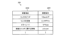
- FIG. 3 is a diagram illustrating an example of a failure condition table stored in the storage unit of the communication cable.
- FIG. 4 is a diagram illustrating an example of the collection item table stored in the storage unit of the communication cable.
- FIG. 5 is a block diagram illustrating an example of the switch device.
- FIG. 6 is a block diagram illustrating an example of the switch device.
- FIG. 7 is a diagram illustrating an example of the failure condition table for each port stored in the storage unit of the switch device.
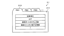
- FIG. 8 is a diagram illustrating an example of the collection item table for each port stored in the storage unit of the switch device.
- FIG. 1 is a diagram illustrating an example of an information processing system.
- FIG. 2 is a block diagram illustrating an example of a communication cable.
- FIG. 3 is a diagram illustrating an example of a failure condition table stored in
- FIG. 9 is a diagram illustrating an example of the collection information table.
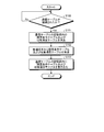
- FIG. 10 is a flowchart illustrating an example of the operation of the switch device.
- FIG. 11 is a flowchart illustrating an example of the operation of the switch device.
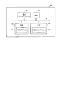
- FIG. 12 is a diagram illustrating an example of a communication device that implements the function of the switch device.
- FIG. 1 is a diagram illustrating an example of an information processing system 10.
- the information processing system 10 includes a plurality of switch devices 30 (30-1 to 30-4) and a plurality of communication cables 20 (20-1 to 20-4) that connect the respective switch devices 30.
- the communication cables 20-1 to 20-4 are collectively referred to without being distinguished, they are referred to as communication cables 20, and the switch devices 30-1 to 30-4 are collectively referred to without being distinguished. In this case, the switch device 30 is described.
- Each switch device 30 is connected to another switch device 30 via the communication cable 20.
- the switch device 30 is an example of an information processing device.
- each switch device 30 has a fabric function.
- the plurality of switch devices 30 connected to each other via the communication cable 20 virtually operate as one switch, and relay the communication data transmitted from the server 12 to the destination server 12.
- the information processing system 10 illustrated in FIG. 1 includes four switch devices 30 connected to each other by the communication cable 20, but the information processing system 10 includes four or more units connected to each other by the communication cable 20.
- the switch device 30 may be included.
- the switch device 30 When a fabric is constituted by a plurality of switch devices 30, one of the plurality of switch devices 30 constituting the fabric manages and monitors the other switch devices 30. Further, an ID number is assigned to each switch device 30 constituting the fabric, and each switch device 30 is managed by the ID.
- the switch device 30 that manages and monitors the other switch device 30 is referred to as a management switch, and the other switch device 30 that is managed by the management switch is an unmanaged switch. Call it.
- the switch device 30-1 is a management switch
- the switch devices 30-2 to 30-4 are non-management switches.
- the test is performed by changing the connection of the plurality of switch devices 30 or changing the types of communication cables connecting the switch devices 30 in various ways.
- Each switch device 30 monitors statistical information such as an error rate of communication data transmitted and received via a communication cable. For example, when the error rate of communication data transmitted and received via a communication cable exceeds a set threshold, the switch device 30 detects a communication failure via the communication cable and detects the occurrence of the failure. Notify a predetermined device (for example, a management switch). Since characteristics such as transmission speed and error rate differ depending on the type of communication cable connecting the switch devices 30, a threshold value for detecting the occurrence of a failure is set in the switch device 30 according to the type of communication cable to be connected. Is done.
- a threshold value corresponding to the type of the connected communication cable is set each time the type of the communication cable connected to the switch device 30 is changed.
- the switch device 30 is set. If the worker who performs the fabric test sets the threshold value according to the type of the connected communication cable in each switch device 30 every time the type of the communication cable connected to the switch device 30 is changed, the work The burden on the person is great.
- the failure condition table including the conditions used for determining the occurrence of failure corresponding to the type of the communication cable 20 in the storage unit provided in each communication cable 20.
- the switch device 30 reads the failure condition table from the storage unit of the communication cable 20 and stores it in the storage unit in the switch device 30.
- the switch device 30 monitors statistical information such as an error rate of communication data transmitted and received via the communication cable 20. Then, when the statistical information of the communication data transmitted and received via the communication cable 20 satisfies the conditions in the failure condition table, the switch device 30 detects the occurrence of the failure, and the detected failure information is predetermined. To the device. Thereby, the information processing system 10 is an operator who sets conditions such as a threshold corresponding to the type of the communication cable 20 in the switch device 30 each time the type of the communication cable 20 connected to the switch device 30 is changed. Can be saved.
- a collection item table including items of information collected when a failure occurs is stored in the storage unit provided in each communication cable 20.
- Each switch device 30 reads the collection item table from the storage unit of the communication cable 20 and stores it in the storage unit in the switch device 30 when the communication cable 20 is connected.
- the switch device 30 When the switch device 30 detects a communication failure based on statistical information such as an error rate of communication data transmitted and received via the communication cable 20, it collects information corresponding to the items included in the collection item table. To do. Then, the switch device 30 notifies the collected information together with the detected failure information to a predetermined device (for example, management switch). As a result, the information processing system 10 can reduce the burden on the operator for collecting information used for investigating the location of the failure and the cause of the failure when a communication failure occurs.
- a predetermined device for example, management switch
- FIG. 2 is a block diagram illustrating an example of the communication cable 20.
- the communication cable 20 includes a cable body 25 and connectors 21 provided at both ends of the cable body 25.
- the cable body 25 is, for example, a Twinax (2-core coaxial strand) cable.
- Each connector 21 is provided with a storage unit 22.
- the storage unit 22 is realized by a nonvolatile memory such as an EEPROM (Electrically Erasable Programmable Read-Only Memory).
- the storage unit 22 stores a failure condition table 220 and a collection item table 221.
- FIG. 3 is a diagram illustrating an example of the failure condition table 220 stored in the storage unit 22 of the communication cable 20.
- a failure condition 2201 is stored in association with the failure item 2200.
- the failure item 2200 indicates an item of information used for determining the occurrence of a failure.
- the failure condition 2201 indicates a condition satisfied by information corresponding to the failure item 2200 when it is determined that a failure has occurred.
- link speed is an item indicating the transmission speed of communication data via the communication cable 20.
- link state indicates whether or not communication with another communication cable 20 (hereinafter referred to as an adjacent switch) connected via the communication cable 20 is possible. It is an item.
- error rate is an item indicating the ratio of communication data in error among communication data received via the communication cable 20.
- “information about adjacent switch” is information about the adjacent switch connected via the communication cable 20 storing the failure condition table 220 shown in FIG. Examples of information related to the adjacent switch include the MAC address and switch ID of the adjacent switch. The switch device 30 acquires these pieces of information from the adjacent switch via the communication cable 20.
- “Unknown” described in the column of the failure condition 2201 indicates a state in which acquisition of information of at least one item from the adjacent switch has failed among items predetermined as information related to the adjacent switch.
- the storage unit 22 of the communication cable 20 having a maximum transmission rate of 10 Gbps has a failure condition such as a link speed of 1 Gbps or less and an error rate of 10 ⁇ 8 or more as a failure condition that is determined to be a failure.
- a failure condition table 220 is stored.
- the storage unit 22 of the communication cable 20 having a maximum transmission rate of 40 Gbps includes a failure condition including a failure condition such as a link speed of 10 Gbps or less and an error rate of 10 ⁇ 7 or more as a failure condition that is determined to be a failure.
- a condition table 220 is stored.
- the storage unit 22 of the communication cable 20 having the maximum transmission speed of 56 Gbps includes a failure condition including a failure condition such as a link speed of 40 Gbps or less and an error rate of 10 ⁇ 6 or more as a failure condition determined to be a failure.
- a condition table 220 is stored. As described above, the storage unit 22 of the communication cable 20 stores the failure condition table 220 including the failure condition corresponding to the type of the communication cable 20.
- FIG. 4 is a diagram illustrating an example of the collection item table 221 stored in the storage unit 22 of the communication cable 20.
- the collection item table 221 stores items of information collected when any failure condition included in the failure condition table 220 is satisfied.
- log is information that records the operating status of the switch device 30, and includes a record of events that have occurred in the switch device 30.
- 4 is the counter value of the communication port of the switch device 30 to which the communication cable 20 storing the collection item table 221 illustrated in FIG. 4 is connected.
- the communication port counter value for example, the number of transmitted packets, the number of received packets, the number of error packets, and the like can be considered.
- information on adjacent switch illustrated in FIG. 4 indicates information that can be acquired from the adjacent switch among items predetermined as information on the adjacent switch.
- the connector 21 is connected to the communication port of the switch device 30.
- Information in the storage unit 22 is read by the switch device 30 via the serial interface terminal 23.
- Communication data transmitted and received between the switch devices 30 connected by the communication cable 20 propagates from the switch device 30 to the cable body 25 via the communication interface terminal 24 and is transmitted by the cable body 25.
- Switch device 30 5 and 6 are block diagrams illustrating an example of the switch device 30.
- FIG. FIG. 5 shows the switch device 30 that operates as an unmanaged switch
- FIG. 6 shows the switch device 30 that operates as a managed switch.
- Each switch device 30 operates as an unmanaged switch or a managed switch.
- the switch device 30 that operates as an unmanaged switch includes a storage unit 31, a reading unit 32, a switching processing unit 33, a determination unit 34, a collection unit 35, a transmission unit 36, a writing unit 37, and a maintenance unit.
- a port 38 and a plurality of communication ports 39 are provided.
- the storage unit 31 stores a port-specific failure condition table 310, a port-specific collection item table 311, port information 312, and a log 313.
- FIG. 7 is a diagram illustrating an example of the failure condition table 310 for each port stored in the storage unit 31 of the switch device 30.
- the failure condition table 3101 for each port stores a failure condition table 3101 for each port ID 3100 that identifies each communication port 39.
- each failure condition table 3101 for example, the same information as the failure condition table 220 described with reference to FIG. 3 is stored.
- FIG. 8 is a diagram illustrating an example of the port-specific collection item table 311 stored in the storage unit 31 of the switch device 30.
- the collection item table 311 for each port stores a collection item table 3111 for each port ID 3110 for identifying each communication port 39.
- Each collection item table 3111 stores, for example, the same information as the collection item table 221 described with reference to FIG.
- Information corresponding to the collection items stored in each collection item table 3111 is stored in the port information 312 and the log 313 in the storage unit 31.
- the port information 312 stores, for each communication port 39, statistical information of communication data transmitted and received via the communication port 39, information regarding adjacent switches connected via the communication cable 20, and the like. Information such as the operating status of the switch device 30 is recorded in the log 313.
- the reading unit 32 monitors whether or not the communication cable 20 is connected to the communication port 39.
- the reading unit 32 uses the failure condition table 3101 associated with the port ID of the communication port 39 to which the communication cable 20 is connected to the failure condition for each port in the storage unit 31. It is specified in the table 310. Then, the reading unit 32 deletes the data in the specified failure condition table 3101.
- the reading unit 32 stores the collection item table 3111 associated with the port ID of the communication port 39 to which the communication cable 20 is connected in the storage unit 31. It is specified in the collection item table 311 for each port. Then, the reading unit 32 deletes the data in the identified collection item table 3111.
- the reading unit 32 reads the data in the failure condition table 220 and the data in the collection item table 221 from the storage unit 22 of the communication cable 20 via the communication port 39. Then, the reading unit 32 stores the data in the failure condition table 220 read from the storage unit 22 of the communication cable 20 in the failure condition table 3101 specified in the failure condition table 310 for each port. The reading unit 32 stores the data in the collection item table 221 read from the storage unit 22 of the communication cable 20 in the collection item table 3111 specified in the port-specific collection item table 311.
- the switching processing unit 33 communicates communication data received from another switch device 30 via the communication cable 20 connected to the communication port 39 in accordance with information such as the destination of the communication data. A process of relaying via the cable 20 is performed. In the present embodiment, the switching processing unit 33 relays communication data in cooperation with other switch devices 30 based on the fabric function. In addition, the switching processing unit 33 records an operation state such as an event generated according to processing such as relaying of communication data in the log 313 in the storage unit 31.
- the determination unit 34 refers to the failure condition table 3101 and the port information 312 in the failure condition table 310 for each port for each communication port 39 to which the communication cable 20 is connected at every predetermined timing. Then, the determination unit 34 determines whether any failure condition included in the failure condition table 3101 is satisfied. When it is determined that any of the failure conditions included in the failure condition table 3101 is satisfied, the determination unit 34 notifies the collection unit 35 of a port ID that identifies the communication port 39 that satisfies the failure condition. In this case, the determination unit 34 may notify the collection unit 35 of the failure item associated with the failure condition.
- the collection unit 35 When the collection unit 35 is notified of the port ID of the communication port 39 from the determination unit 34, the collection unit 35 identifies the collection item table 3111 associated with the notified port ID in the collection item table 311 for each port. Then, the collection unit 35 collects information corresponding to each collection item stored in the specified collection item table 3111 from the port information 312 or the log 313. Then, the collection unit 35 sends the information collected for each collection item to the transmission unit 36 together with the port ID of the communication port 39 that satisfies the failure condition.
- the transmission unit 36 When the transmission unit 36 receives the information collected for each collection item and the port ID of the communication port 39 satisfying the failure condition from the collection unit 35, the transmission unit 36 identifies the received information as the own device. Along with the switch ID, it is transmitted to a predetermined device.
- the predetermined device is, for example, a management switch.
- the transmission unit 36 includes the information collected for each collection item, the port ID of the communication port 39 that satisfies the failure condition, and the communication port 39 that satisfies the failure condition together with the switch ID that identifies the own device. You may transmit from other communication ports 39. Thereby, the transmission unit 36 can more reliably deliver the information collected for each collection item and the port ID of the communication port 39 that satisfies the failure condition to a predetermined device.
- the writing unit 37 determines whether the communication cable 20 is connected to any one of the communication ports 39.
- the writing unit 37 accesses the storage unit 22 of the communication cable 20 and deletes the failure condition table 220 and the collection item table 221 in the storage unit 22. .
- the writing unit 37 transmits the data of the failure condition table 220 and the collection item table 221 to the communication cable. It is stored in 20 storage units 22.
- the switch device 30 that operates as a management switch includes a storage unit 31, a reading unit 32, a switching processing unit 33, a determination unit 34, a collection unit 35, a writing unit 37, a maintenance port 38, a plurality of A communication port 39 and an output unit 40 are provided. Except for the points described below, in FIG. 6, the components denoted by the same reference numerals as those in FIG. 5 have the same or similar functions as those in FIG.
- the storage unit 31 stores a port-specific failure condition table 310, a port-specific collection item table 311, port information 312, a log 313, and a collection information table 314.
- FIG. 9 is a diagram illustrating an example of the collection information table 314.
- the collection information table 314 stores an individual table 3141 for each switch ID 3140 for identifying each switch device 30.
- an individual table 3143 is stored for each port ID 3142 that identifies each communication port 39.
- Each individual table 3143 stores collection information 3145 in association with the collection item 3144.
- the collection unit 35 When the collection unit 35 is notified of the port ID of the communication port 39 from the determination unit 34, the collection unit 35 identifies the individual table associated with the notified port ID in the collection item table 311 for each port.
- the collection unit 35 collects information corresponding to each item stored in the specified individual table from the port information 312 or the log 313. Then, the collection unit 35 refers to the collection information table 314 in the storage unit 31 and identifies an individual table associated with the switch ID of the own device. Then, the collection unit 35 refers to the identified individual table and identifies the individual table associated with the port ID notified from the determination unit 34. Then, the collection unit 35 stores the information collected for each collection item in the specified individual table.
- the collection unit 35 collects information collected for each collection item together with the switch ID from the other switch device 30 that is an unmanaged switch via the communication cable 20 connected to any one of the communication ports 39, and a fault.
- the port ID of the communication port 39 that satisfies the condition is received.
- the collection unit 35 refers to the switching processing unit 3314 in the storage unit 31 and identifies the individual table associated with the switch ID received from the unmanaged switch.
- the collection unit 35 refers to the identified individual table and identifies the individual table associated with the port ID received from the unmanaged switch.
- the collection part 35 stores the information collected for every collection item received from the non-management switch in the specified individual table.
- the output unit 40 acquires the collection information table 314 from the storage unit 31 when instructed to output the collection information table 314 from the management terminal 11 via the maintenance port 38. Then, the output unit 40 outputs the data in the collection information table 314 to the management terminal 11 via the maintenance port 38.
- the management terminal 11 outputs the data in the collection information table 314 output from the management switch by displaying it on a display or the like.
- FIG. 10 shows an example of the operation of the switch device 30 when the failure condition table 220 and the collection item table 221 are written in the communication cable 20.
- the switch device 30 starts the operation illustrated in FIG.
- the writing unit 37 determines whether or not the communication cable 20 is connected to any one of the communication ports 39 (S100). When the communication cable 20 is connected to any one of the communication ports 39 (S100: Yes), the writing unit 37 accesses the storage unit 22 of the communication cable 20, and the failure condition table 220 and the collected items in the storage unit 22 are accessed. The table 221 is deleted (S101).
- the writing unit 37 receives the data of the failure condition table 220 and the collection item table 221 from the management terminal 11 via the maintenance port 38 (S102). Then, the writing unit 37 writes the received data of the failure condition table 220 and the collection item table 221 in the storage unit 22 of the communication cable 20 (S103). And the switch apparatus 30 complete
- FIG. 11 shows an example of an operation at the time of operation of the switch device 30 when the failure determination is performed based on the failure condition table 220 and the collection item table 221 stored in the communication cable 20. Note that the operation shown in FIG. 11 is performed for each communication port 39 by the switch device 30.
- the reading unit 32 monitors whether or not the communication cable 20 is connected to any one of the communication ports 39 (S200).
- the reading unit 32 stores the failure condition table 3101 associated with the port ID of the communication port 39 to which the communication cable 20 is connected, It is specified in the failure condition table 310 for each port. Then, the reading unit 32 deletes the data in the specified failure condition table 3101 (S201).
- the reading unit 32 specifies the collection item table 3111 associated with the port ID of the communication port 39 to which the communication cable 20 is connected in the port-specific collection item table 311 in the storage unit 31. Then, the reading unit 32 deletes the data in the specified collection item table 3111 (S201).
- the reading unit 32 reads the data in the failure condition table 220 and the data in the collection item table 221 from the storage unit 22 of the communication cable 20 via the communication port 39 (S202). Then, the reading unit 32 stores the data in the failure condition table 220 read from the storage unit 22 of the communication cable 20 in the failure condition table 3101 specified in step S201 (S203). Further, the reading unit 32 stores the data in the collection item table 221 read from the storage unit 22 of the communication cable 20 in the collection item table 3111 identified in step S201 (S203).
- the switching processing unit 33 initializes the communication cable 204 in the storage unit 31 (S204). And the switching process part 33 starts the process which relays communication data via the communication port 39 to which the communication cable 20 was connected.
- the determination unit 34 refers to the failure condition table 3101 and the port information 312 in the failure condition table for each port 310 at every predetermined timing for the communication port 39 to which the communication cable 20 is connected. Then, the determination unit 34 determines whether any failure condition included in the failure condition table 3101 is satisfied (S205).
- the determination unit 34 determines that any of the failure conditions included in the failure condition table 3101 is satisfied (S205: Yes)
- the determination unit 34 notifies the collection unit 35 of the port ID of the communication port 39 that satisfies the failure condition. .
- the collection unit 35 specifies the collection item table 3111 associated with the port ID notified from the determination unit 34 in the collection item table 311 for each port. Then, the collection unit 35 collects information corresponding to each collection item stored in the specified collection item table 3111 from the port information 312 or the log 313 (S206).
- the collection unit 35 sends the information collected for each collection item to the transmission unit 36 together with the port ID of the communication port 39 that satisfies the failure condition.
- the transmission unit 36 receives the information collected for each collection item and the port ID of the communication port 39 satisfying the failure condition from the collection unit 35, and uses the received information as a switch ID for identifying the own device. At the same time, for example, it is transmitted to the management switch (S207). And the switching process part 33 performs the process shown to step S204 again.
- the reading unit 32 determines whether or not the communication cable 20 is disconnected from the communication port 39. Is monitored (S208). When the communication cable 20 is not disconnected from the communication port 39 (S208: No), the determination unit 34 executes the process shown in step S205 again. On the other hand, when the communication cable 20 is disconnected from the communication port 39 (S208: Yes), the reading unit 32 executes the process shown in step S200 again.
- the information processing system 10 includes a plurality of switch devices 30 and a plurality of communication cables 20 that connect the switch devices 30 to each other.
- Each communication cable 20 stores a failure condition table 220 including a failure condition used for determining the occurrence of a failure, and a collection item table including items of information collected when the failure condition is satisfied.
- Each switch device 30 includes a communication port 39, a reading unit 32, a determination unit 34, a collection unit 35, and a transmission unit 36.
- the communication cable 20 is connected to the communication port 39.
- the reading unit 32 reads the failure condition table 220 and the collection item table 221 from the storage unit 22 provided in the communication cable 20 when the communication cable 20 is connected to the communication port 39.
- the determination unit 34 determines whether or not the state of communication via the communication cable 20 connected to the communication port 39 satisfies the failure condition included in the failure condition table 220 read by the reading unit 32.
- the collection unit 35 is included in the collection item table 221 read by the reading unit 32 when the determination unit 34 determines that the state of communication via the communication cable 20 connected to the communication port 39 satisfies the failure condition. Collect information corresponding to the collected items.
- the transmission unit 36 transmits the information collected by the collection unit 35 to the management switch. As a result, the information processing system 10 can reduce the burden on the operator in collecting information from each switch device 30 and setting information in each switch device 30.
- the switch device 30 includes the storage unit 31 that stores the failure condition table 3101 and the collection item table 3111 for each communication port 39. Then, the reading unit 32 stores the data of the failure condition table 220 read from the storage unit 22 provided in the communication cable 20 connected to the communication port 39 in the failure condition table 3101 in the storage unit 31. Further, the reading unit 32 stores the data of the collection item table 221 read from the storage unit 22 provided in the communication cable 20 connected to the communication port 39 in the collection item table 3111 in the storage unit 31. Also, the determination unit 34 refers to the collection item table 3111 stored in the storage unit 31 to determine whether the state of communication via the communication port 39 satisfies the failure condition.
- the collection unit 35 refers to the collection item table 3111 stored in the storage unit 31 and collects information corresponding to items included in the collection item table 3111.
- the conditions used for determining the failure corresponding to the type of the communication cable 20 connected to the switch device 30 are automatically set in the switch device 30.
- the information processing system 10 can reduce the burden on the operator for setting information on each switch device 30.
- information used to identify the cause of the failure is automatically collected from each switch device 30 to a predetermined device. Thereby, the information processing system 10 can reduce the burden on the worker who collects information used for investigating the cause of the failure from each switch device 30 when a failure occurs.
- the storage unit 22 stores a failure condition table 220 including failure conditions corresponding to the type of the communication cable 20 provided with the storage unit 22.
- the switch device 30 includes the writing unit 37.
- the writing unit 37 writes the failure condition table 220 and the collection item table 221 received from the management terminal 11 to the storage unit 22 provided in the communication cable 20 connected to the communication port 39. Thereby, the operator who performs the test of the switch device 30 can easily manufacture the communication cable 20 in which the failure condition table 220 and the collection item table 221 are stored in the storage unit 22.
- the transmission unit 36 manages information collected by the collection unit 35 from a communication port 39 different from the communication port 39 determined by the determination unit 34 that the communication state satisfies the failure condition. Send to switch. Thereby, the transmission part 36 can deliver more reliably the information collected by the collection part 35 to predetermined apparatuses, such as a management apparatus.
- each component of each part shown by the figure demonstrated so far does not necessarily need to be physically comprised like illustration.
- the specific form of distribution / integration of each unit is not limited to that shown in the figure, and all or a part thereof may be functionally or physically distributed / integrated in arbitrary units according to various loads or usage conditions. Can be configured.
- the various processing functions of the switch device 30 are all or any part of a CPU (Central Processing Unit) (or a microcomputer such as an MPU (Micro Processing Unit) or MCU (Micro Controller Unit)). May be executed.
- Various processing functions may be executed in whole or in any part on a program that is analyzed and executed by a CPU (or a microcomputer such as an MPU or MCU) or on hardware based on wired logic. Needless to say.
- FIG. 12 is a diagram illustrating an example of the communication device 50 that realizes the function of the switch device 30.
- the communication device 50 includes a communication interface 51, a CPU 52, a RAM (Random Access Memory) 53, and a ROM (Read Only Memory) 54.
- the communication interface 51, CPU 52, RAM 53, and ROM 54 are connected to each other via a bus 55.
- the ROM 54 stores a control program 540 in advance.
- the CPU 52 reads the control program 540 from the ROM 54 and expands it in the RAM 53.
- the CPU52 reads the control program 540 from ROM54. Then, the CPU 52 expands the RAM 53 as the control process 530. Then, the CPU 52 executes the control process 530 developed on the RAM 53 in the above-described embodiment.
- the CPU 52 when the switch device 30 functions as a non-management device, the CPU 52 includes a reading unit 32, a switching processing unit 33, a determination unit 34, a collection unit 35, a transmission unit 36, and a writing unit 37. It performs the same function.
- the CPU 52 when the switch device 30 functions as a management device, the CPU 52 is the same as the reading unit 32, the switching processing unit 33, the determination unit 34, the collection unit 35, the writing unit 37, and the output unit 40. Demonstrate the function. Further, the CPU 52 executes, for example, the processes shown in FIGS. 10 and 11 by executing the control process 530 developed on the RAM 53 in the above-described embodiment.
- control program 540 does not necessarily have to be stored entirely in the ROM 54 from the beginning.
- each program may be stored in a portable recording medium such as an IC card inserted into the communication device 50, and the communication device 50 may acquire and execute each program from the portable recording medium.
- the communication device 50 may acquire and execute each program from another computer or server device storing each program via a wireless communication line, a public line, the Internet, a LAN, a WAN, or the like. Good.
- the collection item table 311 for each port stores the collection item table 3111 for each communication port 39, but the disclosed technique is not limited thereto. For example, if the items of information collected when a failure occurs does not differ for each communication port 39, one collection item table 3111 is stored in the storage unit 31 in common for the plurality of communication ports 39. May be.
- all the switch devices 30 may not have the writing unit 37, and for example, at least one switch device 30 included in the information processing system 10 may have the writing unit 37.
- the switch device 30 having the writing unit 37 does not have the functions of the storage unit 31, the reading unit 32, the switching processing unit 33, the determination unit 34, the collection unit 35, the transmission unit 36, and the output unit 40. Also good.
- the switch device 30 having the writing unit 37 may function as a dedicated device that writes data in the failure condition table 220 and the collection item table 221 in the storage unit 22 of the communication cable 20.
- the collection unit 35 displays the collection items included in the collection item table 3111. Collect all corresponding information.
- the disclosed technology is not limited to this.
- different collection items in the collection item table 3111 may be associated with each failure condition included in the failure condition table 3101.
- the collection unit 35 responds to the failure condition among the collection items included in the collection item table 3111.
- Information corresponding to the collection item to be collected may be collected.
Landscapes
- Engineering & Computer Science (AREA)
- Computer Networks & Wireless Communication (AREA)
- Signal Processing (AREA)
- Computer Security & Cryptography (AREA)
- Data Exchanges In Wide-Area Networks (AREA)
- Small-Scale Networks (AREA)
Abstract
情報処理装置(30)は、一つの態様において、通信ポート(39)と、読込部(32)と、判定部(34)と、収集部(35)と、送信部(36)とを有する。読込部(32)は、通信ポート(39)に通信ケーブルが接続された場合に、通信ケーブルに設けられた記憶部から、障害条件テーブルと収集項目テーブルとを読み込む。判定部(34)は、通信ポート(39)に接続された通信ケーブルを介した通信の状態が障害条件テーブルに含まれている条件を満たすか否かを判定する。収集部(35)は、判定部(34)によって通信ポート(39)に接続された通信ケーブルを介した通信の状態が条件を満たすと判定された場合に、収集項目テーブルに含まれている項目に該当する情報を収集する。送信部(36)は、収集部(35)が収集し情報を、所定の装置へ送信する。
Description
本発明は、情報処理装置および情報処理システムに関する。
出荷段階におけるスイッチ装置の評価では、複数のスイッチ装置同士の接続を様々に変えたり、スイッチ同士の接続に用いられる通信ケーブルの種類を様々に変えて試験が行われることが多い。各スイッチ装置は、通信ケーブルが接続された通信ポートを介して送信および受信される通信データを監視し、通信データの統計値やエラーカウンタの値、隣接する他のスイッチ装置との通信状態等の情報を保持する。
複数のスイッチ装置が接続された通信システムにおいて障害が発生した場合、スイッチ装置の評価を行う作業者は、管理端末を用いて個々のスイッチ装置にアクセスし、スイッチ装置が保持する情報を収集する。そして、作業者は、各スイッチ装置から収集された情報を用いて、障害発生箇所の特定や障害原因の究明等の作業を行う。
また、スイッチ装置には、通信データのエラーレートが所定の閾値を超えた場合に、障害の発生を検出する機能が設けられる場合がある。障害発生の検出に用いられるエラーレートの閾値等の情報は、通信ポートに接続される通信ケーブルの種別によって異なる場合が多い。そのため、スイッチ装置間の接続に用いられる通信ケーブルの種類が変更された場合には、作業者は、管理端末を用いてスイッチ装置にアクセスし、エラーレートの閾値等の情報を、スイッチ装置に接続された通信ケーブルの種別に合わせて変更する。
ところで、評価対象のスイッチ装置の数が多くなると、作業者が管理端末を用いてアクセスするスイッチ装置の数が多くなり、障害発生箇所等を特定するための情報の収集作業にかかる時間が長くなる。また、評価対象のスイッチ装置の数が多くなると、スイッチ装置を接続する通信ケーブルの種類の変更に伴い、エラーレートの閾値等の設定の変更対象となるスイッチ装置の数も多くなる。そのため、スイッチ装置の評価にかかる時間が長くなるという問題があった。
1つの側面では、本発明は、各スイッチ装置からの情報の収集作業および各スイッチ装置への情報の設定作業にかかる作業者の負担を軽減することが可能な情報処理装置および情報処理システムを提供する。
本願の開示する情報処理装置は、一つの態様において、通信ポートと、読込部と、判定部と、収集部と、送信部とを有する。通信ポートには、通信ケーブルが接続される。読込部は、通信ポートに通信ケーブルが接続された場合に、通信ケーブルに設けられた第1の記憶部から、障害発生の判定に用いられる条件を含む障害条件テーブルと、条件が満たされた場合に収集される情報の項目を含む収集項目テーブルとを読み込む。判定部は、通信ポートに接続された通信ケーブルを介した通信の状態が、読込部が読み込んだ障害条件テーブルに含まれている条件を満たすか否かを判定する。収集部は、判定部によって通信ポートに接続された通信ケーブルを介した通信の状態が条件を満たすと判定された場合に、読込部が読み込んだ収集項目テーブルに含まれている項目に該当する情報を収集する。送信部は、収集部によって収集された情報を、所定の装置へ送信する。
本発明の一側面によれば、各情報処理装置からの情報の収集作業および各情報処理装置への情報の設定作業にかかる作業者の負担を軽減することができる。
以下に、本願の開示する情報処理装置および情報処理システムの実施形態を、図面に基づいて詳細に説明する。なお、以下の実施形態は開示の技術を限定するものではない。また、各実施形態は、処理内容を矛盾させない範囲で適宜組み合わせることが可能である。
[情報処理システム10]
図1は、情報処理システム10の一例を示す図である。情報処理システム10は、複数のスイッチ装置30(30-1~30-4)と、それぞれのスイッチ装置30を接続する複数の通信ケーブル20(20-1~20-4)を有する。なお、以下では、通信ケーブル20-1~20-4のそれぞれを区別することなく総称する場合に通信ケーブル20と記載し、スイッチ装置30-1~30-4のそれぞれを区別することなく総称する場合にスイッチ装置30と記載する。
図1は、情報処理システム10の一例を示す図である。情報処理システム10は、複数のスイッチ装置30(30-1~30-4)と、それぞれのスイッチ装置30を接続する複数の通信ケーブル20(20-1~20-4)を有する。なお、以下では、通信ケーブル20-1~20-4のそれぞれを区別することなく総称する場合に通信ケーブル20と記載し、スイッチ装置30-1~30-4のそれぞれを区別することなく総称する場合にスイッチ装置30と記載する。
それぞれのスイッチ装置30は、通信ケーブル20を介して他のスイッチ装置30に接続される。スイッチ装置30は、情報処理装置の一例である。本実施形態において、それぞれのスイッチ装置30は、ファブリックの機能を有する。そして、通信ケーブル20を介して相互に接続された複数のスイッチ装置30は、仮想的に1つのスイッチとして動作し、サーバ12から送信された通信データを宛先のサーバ12へ中継する。なお、図1に例示した情報処理システム10は、通信ケーブル20によって相互に接続された4台のスイッチ装置30を有するが、情報処理システム10は、通信ケーブル20によって相互に接続された4台以上のスイッチ装置30を有してもよい。
複数のスイッチ装置30によってファブリックが構成される場合、ファブリックを構成する複数のスイッチ装置30の中の1台は、他のスイッチ装置30を管理および監視する。また、ファブリックを構成するそれぞれのスイッチ装置30にはID番号が割り当てられ、それぞれのスイッチ装置30はIDによって管理される。以下では、ファブリックを構成する複数のスイッチ装置30の中で、他のスイッチ装置30を管理および監視するスイッチ装置30を管理スイッチと呼び、管理スイッチによって管理される他のスイッチ装置30を非管理スイッチと呼ぶ。図1に例示した情報処理システム10では、例えばスイッチ装置30-1が管理スイッチであり、例えばスイッチ装置30-2~30-4が非管理スイッチである。
ここで、スイッチ装置30の製品出荷段階におけるファブリック機能の評価では、複数のスイッチ装置30の接続を様々に変えたり、スイッチ装置30間を接続する通信ケーブルの種類を様々に変えて試験が行われる。スイッチ装置30間を接続するケーブルには、材質や構成によって、様々な種類が存在する。通信ケーブルの種類が異なると、伝送速度やエラーレート等の特性が異なる。
各スイッチ装置30は、通信ケーブルを介して送信および受信する通信データのエラーレート等の統計情報を監視する。そして、例えば、通信ケーブルを介して送信および受信する通信データのエラーレートが設定された閾値を超えた場合に、スイッチ装置30は、該通信ケーブルを介した通信の障害を検出し、障害発生を所定の装置(例えば管理スイッチ)に通知する。スイッチ装置30間を接続する通信ケーブルの種類によって伝送速度やエラーレート等の特性が異なるため、障害の発生を検出するための閾値は、接続される通信ケーブルの種類に応じてスイッチ装置30に設定される。
スイッチ装置30間を接続する通信ケーブルの種類を変えて行われるファブリック試験では、スイッチ装置30に接続される通信ケーブルの種類が変更される都度、接続された通信ケーブルの種類に応じた閾値等がスイッチ装置30に設定される。ファブリック試験を行う作業者が、スイッチ装置30に接続される通信ケーブルの種類が変更される都度、接続された通信ケーブルの種類に応じた閾値等を個々のスイッチ装置30に設定するとすれば、作業者の負担が大きい。
これに対し、本実施形態の情報処理システム10では、それぞれの通信ケーブル20に設けられた記憶部内に、該通信ケーブル20の種類に対応する、障害発生の判定に用いられる条件を含む障害条件テーブルを記憶させる。そして、スイッチ装置30は、通信ケーブル20が接続された場合に、通信ケーブル20の記憶部から障害条件テーブルを読み出して、スイッチ装置30内の記憶部に記憶する。
スイッチ装置30は、通信ケーブル20を介して送信および受信する通信データのエラーレート等の統計情報を監視する。そして、スイッチ装置30は、通信ケーブル20を介して送信および受信する通信データの統計情報が、障害条件テーブル内の条件を満たした場合に、障害の発生を検出し、検出した障害の情報を所定の装置に通知する。これにより、情報処理システム10は、スイッチ装置30に接続される通信ケーブル20の種類が変更される都度、通信ケーブル20の種類に応じた閾値等の条件を、該スイッチ装置30に設定する作業者の手間を省くことができる。
また、本実施形態の情報処理システム10では、それぞれの通信ケーブル20に設けられた記憶部内に、障害が発生した場合に収集される情報の項目を含む収集項目テーブルを記憶させる。そして、各スイッチ装置30は、通信ケーブル20が接続された場合に、通信ケーブル20の記憶部から、収集項目テーブルを読み出して、スイッチ装置30内の記憶部に記憶する。
そして、スイッチ装置30は、通信ケーブル20を介して送信および受信する通信データのエラーレート等の統計情報に基づいて通信障害を検出した場合、収集項目テーブルに含まれた項目に対応する情報を収集する。そして、スイッチ装置30は、検出した障害の情報と共に、収集した情報を所定の装置(例えば管理スイッチ)に通知する。これにより、情報処理システム10は、通信障害が発生した場合に、障害発生箇所や障害原因の究明に用いられる情報の収集にかかる作業者の負担を軽減することができる。
[通信ケーブル20]
図2は、通信ケーブル20の一例を示すブロック図である。通信ケーブル20は、ケーブル本体25と、ケーブル本体25の両端に設けられたコネクタ21とを有する。ケーブル本体25は、例えばTwinax(2心同軸撚り線)ケーブルである。それぞれのコネクタ21には、記憶部22が設けられている。記憶部22は、例えばEEPROM(Electrically Erasable Programmable Read-Only Memory)等の不揮発性メモリにより実現される。
図2は、通信ケーブル20の一例を示すブロック図である。通信ケーブル20は、ケーブル本体25と、ケーブル本体25の両端に設けられたコネクタ21とを有する。ケーブル本体25は、例えばTwinax(2心同軸撚り線)ケーブルである。それぞれのコネクタ21には、記憶部22が設けられている。記憶部22は、例えばEEPROM(Electrically Erasable Programmable Read-Only Memory)等の不揮発性メモリにより実現される。
記憶部22は、障害条件テーブル220および収集項目テーブル221を記憶する。図3は、通信ケーブル20の記憶部22が記憶する障害条件テーブル220の一例を示す図である。障害条件テーブル220には、障害項目2200に対応付けて、障害条件2201が格納される。障害項目2200は、障害発生の判定に用いられる情報の項目を示す。障害条件2201は、障害発生と判定される場合に、障害項目2200に対応する情報が満たす条件を示す。
ここで、図3において、「リンクスピード」とは、通信ケーブル20を介した通信データの伝送速度を示す項目である。また、図3において、「リンクの状態」とは、通信ケーブル20を介して接続された他の通信ケーブル20(以下、隣接スイッチと呼ぶ)との間で通信が可能な状態か否かを示す項目である。また、図3において、「エラーレート」とは、通信ケーブル20を介して受信された通信データの中で、エラーとなった通信データの割合を示す項目である。
また、図3において、「隣接スイッチに関する情報」とは、図3に示した障害条件テーブル220を記憶する通信ケーブル20を介して接続される隣接スイッチに関する情報である。隣接スイッチに関する情報としては、例えば、隣接スイッチのMACアドレスやスイッチID等がある。スイッチ装置30は、これらの情報を、通信ケーブル20を介して隣接スイッチから取得する。
障害条件2201の欄に記載された「unknown」とは、隣接スイッチに関する情報として予め定められた項目の中で、隣接スイッチから少なくとも1つの項目の情報の取得に失敗した状態を示している。
なお、通信ケーブル20の種類が異なれば、最大伝送速度やエラーレート等の特性が異なる。そして、例えば、最大伝送速度が10Gbpsの通信ケーブル20の記憶部22には、障害発生と判定される障害条件として、リンクスピードが1Gbps以下、および、エラーレートが10-8以上等の障害条件を含む障害条件テーブル220が格納される。また、最大伝送速度が40Gbpsの通信ケーブル20の記憶部22には、障害発生と判定される障害条件として、リンクスピードが10Gbps以下、および、エラーレートが10-7以上等の障害条件を含む障害条件テーブル220が格納される。また、最大伝送速度が56Gbpsの通信ケーブル20の記憶部22には、障害発生と判定される障害条件として、リンクスピードが40Gbps以下、および、エラーレートが10-6以上等の障害条件を含む障害条件テーブル220が格納される。このように、通信ケーブル20の記憶部22には、該通信ケーブル20の種類に応じた障害条件を含む障害条件テーブル220が格納される。
図4は、通信ケーブル20の記憶部22が記憶する収集項目テーブル221の一例を示す図である。収集項目テーブル221には、障害条件テーブル220に含まれるいずれかの障害条件が満たされた場合に収集される情報の項目が格納される。
図4に例示した収集項目テーブル221において、「ログ」とは、スイッチ装置30の動作状況を記録した情報であって、スイッチ装置30において発生したイベントの記録が含まれる。また、図4に例示した「通信ポートのカウンタ値」とは、図4に例示した収集項目テーブル221を記憶する通信ケーブル20が接続されたスイッチ装置30の通信ポートのカウンタ値である。通信ポートのカウンタ値としては、例えば、送信パケット数、受信パケット数、エラーパケット数等が考えられる。また、図4に例示した「隣接スイッチに関する情報」とは、隣接スイッチに関する情報として予め定められた項目の中で、隣接スイッチから取得することができている情報を示している。
図2に戻って説明を続ける。コネクタ21は、スイッチ装置30の通信ポートに接続される。記憶部22内の情報は、シリアルインターフェイス端子23を介してスイッチ装置30によって読み出される。通信ケーブル20によって接続されたスイッチ装置30間で送信および受信される通信データは、通信インターフェイス端子24を介して、スイッチ装置30からケーブル本体25に伝搬し、ケーブル本体25によって伝送される。
[スイッチ装置30]
図5および図6は、スイッチ装置30の一例を示すブロック図である。図5は、非管理スイッチとして動作するスイッチ装置30を示しており、図6は、管理スイッチとして動作するスイッチ装置30を示している。それぞれのスイッチ装置30は、非管理スイッチまたは管理スイッチとして動作する。
図5および図6は、スイッチ装置30の一例を示すブロック図である。図5は、非管理スイッチとして動作するスイッチ装置30を示しており、図6は、管理スイッチとして動作するスイッチ装置30を示している。それぞれのスイッチ装置30は、非管理スイッチまたは管理スイッチとして動作する。
非管理スイッチとして動作するスイッチ装置30は、例えば図5に示すように、記憶部31、読込部32、スイッチング処理部33、判定部34、収集部35、送信部36、書込部37、保守ポート38、および複数の通信ポート39を有する。
記憶部31は、ポート別障害条件テーブル310、ポート別収集項目テーブル311、ポート情報312、およびログ313を記憶する。図7は、スイッチ装置30の記憶部31が記憶するポート別障害条件テーブル310の一例を示す図である。ポート別障害条件テーブル310には、例えば図7に示すように、それぞれの通信ポート39を識別するポートID3100毎に、障害条件テーブル3101が格納される。それぞれの障害条件テーブル3101には、例えば図3を用いて説明した障害条件テーブル220と同様の情報が格納される。
図8は、スイッチ装置30の記憶部31が記憶するポート別収集項目テーブル311の一例を示す図である。ポート別収集項目テーブル311には、例えば図8に示すように、それぞれの通信ポート39を識別するポートID3110毎に、収集項目テーブル3111が格納される。それぞれの収集項目テーブル3111には、例えば図4を用いて説明した収集項目テーブル221と同様の情報が格納される。それぞれの収集項目テーブル3111に格納された収集項目に対応する情報は、記憶部31内のポート情報312やログ313等に格納されている。
ポート情報312には、通信ポート39毎に、通信ポート39を介して送信および受信された通信データの統計情報や、通信ケーブル20を介して接続された隣接スイッチに関する情報等が格納される。ログ313には、スイッチ装置30の動作状況等の情報が記録される。
読込部32は、通信ポート39に通信ケーブル20が接続されたか否かを監視する。通信ポート39に通信ケーブル20が接続された場合、読込部32は、通信ケーブル20が接続された通信ポート39のポートIDに対応付けられた障害条件テーブル3101を、記憶部31のポート別障害条件テーブル310内で特定する。そして、読込部32は、特定した障害条件テーブル3101内のデータを消去する。同様に、通信ポート39に通信ケーブル20が接続された場合、読込部32は、通信ケーブル20が接続された通信ポート39のポートIDに対応付けられた収集項目テーブル3111を、記憶部31内のポート別収集項目テーブル311内で特定する。そして、読込部32は、特定した収集項目テーブル3111内のデータを消去する。
そして、読込部32は、通信ポート39を介して、通信ケーブル20の記憶部22から障害条件テーブル220内のデータおよび収集項目テーブル221内のデータを読み出す。そして、読込部32は、通信ケーブル20の記憶部22から読み出した障害条件テーブル220内のデータを、ポート別障害条件テーブル310内で特定した障害条件テーブル3101に格納する。また、読込部32は、通信ケーブル20の記憶部22から読み出した収集項目テーブル221内のデータを、ポート別収集項目テーブル311内で特定した収集項目テーブル3111に格納する。
スイッチング処理部33は、通信ポート39に接続された通信ケーブル20を介して他のスイッチ装置30から受信した通信データを、通信データの宛先等の情報に従って、他の通信ポート39に接続された通信ケーブル20を介して中継する処理を行う。本実施形態において、スイッチング処理部33は、ファブリックの機能に基づいて、他のスイッチ装置30と連係して通信データの中継を行う。また、スイッチング処理部33は、通信データの中継等の処理に応じて発生したイベント等の動作状況を記憶部31内のログ313に記録する。
判定部34は、通信ケーブル20が接続されたそれぞれの通信ポート39について、所定のタイミング毎に、ポート別障害条件テーブル310内の障害条件テーブル3101およびポート情報312を参照する。そして、判定部34は、障害条件テーブル3101に含まれるいずれかの障害条件が満たされたか否かを判定する。障害条件テーブル3101に含まれるいずれかの障害条件が満たされたと判定した場合、判定部34は、障害条件が満たされた通信ポート39を識別するポートIDを、収集部35に通知する。この場合、判定部34は、障害条件に対応付けられている障害項目も収集部35に通知してもよい。
収集部35は、判定部34から通信ポート39のポートIDを通知された場合に、通知されたポートIDに対応付けられた収集項目テーブル3111をポート別収集項目テーブル311内で特定する。そして、収集部35は、特定した収集項目テーブル3111に格納されたそれぞれの収集項目に対応する情報をポート情報312またはログ313から収集する。そして、収集部35は、収集項目毎に収集した情報を、障害条件が満たされた通信ポート39のポートIDと共に、送信部36へ送る。
送信部36は、収集項目毎に収集された情報と、障害条件が満たされた通信ポート39のポートIDとを収集部35から受け取った場合に、受け取ったこれらの情報を、自装置を識別するスイッチIDと共に、予め定められた装置へ送信する。予め定められた装置とは、例えば管理スイッチである。なお、送信部36は、収集項目毎に収集された情報と、障害条件が満たされた通信ポート39のポートIDとを、自装置を識別するスイッチIDと共に、障害条件が満たされた通信ポート39以外の通信ポート39から送信してもよい。これにより、送信部36は、収集項目毎に収集された情報と、障害条件が満たされた通信ポート39のポートIDとを、より確実に予め定められた装置に届けることができる。
書込部37は、保守ポート38を介して管理端末11から書込み開始を示す信号を受信した場合、いずれかの通信ポート39に通信ケーブル20が接続されたか否かを判定する。いずれかの通信ポート39に通信ケーブル20が接続された場合、書込部37は、通信ケーブル20の記憶部22にアクセスし、記憶部22内の障害条件テーブル220および収集項目テーブル221を消去する。
次に、保守ポート38を介して管理端末11から障害条件テーブル220および収集項目テーブル221のデータを受信した場合、書込部37は、障害条件テーブル220および収集項目テーブル221のデータを、通信ケーブル20の記憶部22内に格納する。
管理スイッチとして動作するスイッチ装置30は、例えば図6に示すように、記憶部31、読込部32、スイッチング処理部33、判定部34、収集部35、書込部37、保守ポート38、複数の通信ポート39、および出力部40を有する。なお、以下に説明する点を除き、図6において、図5と同じ符号を付した構成は、図5における構成と同一または同様の機能を有するため説明を省略する。
記憶部31は、ポート別障害条件テーブル310、ポート別収集項目テーブル311、ポート情報312、ログ313、および収集情報テーブル314を記憶する。図9は、収集情報テーブル314の一例を示す図である。収集情報テーブル314には、それぞれのスイッチ装置30を識別するスイッチID3140毎に、個別テーブル3141が格納される。それぞれの個別テーブル3141には、それぞれの通信ポート39を識別するポートID3142毎に、個別テーブル3143が格納される。それぞれの個別テーブル3143には、収集項目3144に対応付けて、収集情報3145が格納される。
収集部35は、判定部34から通信ポート39のポートIDを通知された場合に、通知されたポートIDに対応付けられた個別テーブルをポート別収集項目テーブル311内で特定する。そして、収集部35は、特定した個別テーブルに格納されたそれぞれの項目に対応する情報をポート情報312またはログ313から収集する。そして、収集部35は、記憶部31内の収集情報テーブル314を参照して、自装置のスイッチIDに対応付けられた個別テーブルを特定する。そして、収集部35は、特定した個別テーブルを参照して、判定部34から通知されたポートIDに対応付けられた個別テーブルを特定する。そして、収集部35は、特定した個別テーブルに、収集項目毎に収集した情報を格納する。
また、収集部35は、いずれかの通信ポート39に接続された通信ケーブル20を介して非管理スイッチである他のスイッチ装置30から、スイッチIDと共に、収集項目毎に収集された情報と、障害条件が満たされた通信ポート39のポートIDとを受信する。そして、収集部35は、記憶部31内のスイッチング処理部3314を参照して、非管理スイッチから受信したスイッチIDに対応付けられた個別テーブルを特定する。そして、収集部35は、特定した個別テーブルを参照して、非管理スイッチから受信したポートIDに対応付けられた個別テーブルを特定する。そして、収集部35は、特定した個別テーブルに、非管理スイッチから受信した、収集項目毎に収集された情報を格納する。
出力部40は、保守ポート38を介して管理端末11から収集情報テーブル314の出力を指示された場合に、記憶部31から収集情報テーブル314を取得する。そして、出力部40は、収集情報テーブル314内のデータを、保守ポート38を介して管理端末11へ出力する。管理端末11は、管理スイッチから出力された収集情報テーブル314内のデータを、ディスプレイに表示する等により出力する。これにより、情報処理システム10は、通信障害が発生した場合に、障害発生箇所や障害原因の究明に用いられる情報の収集にかかる作業者の負担を軽減することができる。
[スイッチ装置30の動作]
図10および図11は、スイッチ装置30の動作の一例を示すフローチャートである。図10は、通信ケーブル20に障害条件テーブル220および収集項目テーブル221を書き込む場合のスイッチ装置30の動作の一例を示す。例えば、保守ポート38に管理端末11が接続され、管理端末11から書込み開始を示す信号を受信した場合に、スイッチ装置30は、図10に示す動作を開始する。
図10および図11は、スイッチ装置30の動作の一例を示すフローチャートである。図10は、通信ケーブル20に障害条件テーブル220および収集項目テーブル221を書き込む場合のスイッチ装置30の動作の一例を示す。例えば、保守ポート38に管理端末11が接続され、管理端末11から書込み開始を示す信号を受信した場合に、スイッチ装置30は、図10に示す動作を開始する。
まず、書込部37は、いずれかの通信ポート39に通信ケーブル20が接続されたか否かを判定する(S100)。いずれかの通信ポート39に通信ケーブル20が接続された場合(S100:Yes)、書込部37は、通信ケーブル20の記憶部22にアクセスし、記憶部22内の障害条件テーブル220および収集項目テーブル221を消去する(S101)。
次に、書込部37は、保守ポート38を介して管理端末11から障害条件テーブル220および収集項目テーブル221のデータを受信する(S102)。そして、書込部37は、受信した障害条件テーブル220および収集項目テーブル221のデータを、通信ケーブル20の記憶部22内に書き込む(S103)。そして、スイッチ装置30は、本フローチャートに示した動作を終了する。
図11は、通信ケーブル20が記憶する障害条件テーブル220および収集項目テーブル221に基づいて障害判定を行う場合のスイッチ装置30の運用時の動作の一例を示す。なお、図11に示す動作は、スイッチ装置30が各通信ポート39について行われる。
まず、読込部32は、いずれかの通信ポート39に通信ケーブル20が接続されたか否かを監視する(S200)。いずれかの通信ポート39に通信ケーブル20が接続された場合(S200:Yes)、読込部32は、通信ケーブル20が接続された通信ポート39のポートIDに対応付けられた障害条件テーブル3101を、ポート別障害条件テーブル310内で特定する。そして、読込部32は、特定した障害条件テーブル3101内のデータを消去する(S201)。
また、読込部32は、通信ケーブル20が接続された通信ポート39のポートIDに対応付けられた収集項目テーブル3111を、記憶部31内のポート別収集項目テーブル311内で特定する。そして、読込部32は、特定した収集項目テーブル3111内のデータを消去する(S201)。
次に、読込部32は、通信ポート39を介して、通信ケーブル20の記憶部22から障害条件テーブル220内のデータおよび収集項目テーブル221内のデータを読み出す(S202)。そして、読込部32は、通信ケーブル20の記憶部22から読み出した障害条件テーブル220内のデータを、ステップS201において特定した障害条件テーブル3101に格納する(S203)。また、読込部32は、通信ケーブル20の記憶部22から読み出した収集項目テーブル221内のデータを、ステップS201において特定した収集項目テーブル3111に格納する(S203)。
次に、スイッチング処理部33は、記憶部31内の通信ケーブル204を初期化する(S204)。そして、スイッチング処理部33は、通信ケーブル20が接続された通信ポート39を介して、通信データを中継する処理を開始する。
次に、判定部34は、通信ケーブル20が接続された通信ポート39について、所定のタイミング毎に、ポート別障害条件テーブル310内の障害条件テーブル3101およびポート情報312を参照する。そして、判定部34は、障害条件テーブル3101に含まれるいずれかの障害条件が満たされたか否かを判定する(S205)。
判定部34は、障害条件テーブル3101に含まれるいずれかの障害条件が満たされたと判定した場合(S205:Yes)、障害条件が満たされた通信ポート39のポートIDを、収集部35に通知する。収集部35は、判定部34から通知されたポートIDに対応付けられた収集項目テーブル3111を、ポート別収集項目テーブル311内で特定する。そして、収集部35は、特定した収集項目テーブル3111に格納されたそれぞれの収集項目に対応する情報をポート情報312またはログ313から収集する(S206)。
次に、収集部35は、収集項目毎に収集した情報を、障害条件が満たされた通信ポート39のポートIDと共に、送信部36へ送る。送信部36は、収集部35から、収集項目毎に収集された情報と、障害条件が満たされた通信ポート39のポートIDとを受け取り、受け取ったこれらの情報を、自装置を識別するスイッチIDと共に、例えば管理スイッチへ送信する(S207)。そして、スイッチング処理部33は、再びステップS204に示した処理を実行する。
一方、判定部34が、障害条件テーブル3101に含まれるいずれの障害条件も満たされていないと判定した場合(S205:No)、読込部32は、通信ポート39から通信ケーブル20が抜かれたか否かを監視する(S208)。通信ポート39から通信ケーブル20が抜かれていない場合(S208:No)、判定部34は、再びステップS205に示した処理を実行する。一方、通信ポート39から通信ケーブル20が抜かれた場合(S208:Yes)、読込部32は、再びステップS200に示した処理を実行する。
[実施形態の効果]
以上、実施形態について説明した。本実施形態の情報処理システム10は、複数のスイッチ装置30と、スイッチ装置30同士を接続する複数の通信ケーブル20とを有する。それぞれの通信ケーブル20は、障害発生の判定に用いられる障害条件を含む障害条件テーブル220と、障害条件が満たされた場合に収集される情報の項目を含む収集項目テーブルとを記憶する記憶部22を有する。それぞれのスイッチ装置30は、通信ポート39と、読込部32と、判定部34と、収集部35と、送信部36とを有する。通信ポート39には、通信ケーブル20が接続される。読込部32は、通信ポート39に通信ケーブル20が接続された場合に、通信ケーブル20に設けられた記憶部22から障害条件テーブル220と収集項目テーブル221とを読み込む。判定部34は、通信ポート39に接続された通信ケーブル20を介した通信の状態が、読込部32が読み込んだ障害条件テーブル220に含まれている障害条件を満たすか否かを判定する。収集部35は、判定部34によって通信ポート39に接続された通信ケーブル20を介した通信の状態が障害条件を満たすと判定された場合に、読込部32が読み込んだ収集項目テーブル221に含まれている収集項目に該当する情報を収集する。送信部36は、収集部35によって収集された情報を、管理スイッチへ送信する。これにより、情報処理システム10は、各スイッチ装置30からの情報の収集作業および各スイッチ装置30への情報の設定作業にかかる作業者の負担を軽減することができる。
以上、実施形態について説明した。本実施形態の情報処理システム10は、複数のスイッチ装置30と、スイッチ装置30同士を接続する複数の通信ケーブル20とを有する。それぞれの通信ケーブル20は、障害発生の判定に用いられる障害条件を含む障害条件テーブル220と、障害条件が満たされた場合に収集される情報の項目を含む収集項目テーブルとを記憶する記憶部22を有する。それぞれのスイッチ装置30は、通信ポート39と、読込部32と、判定部34と、収集部35と、送信部36とを有する。通信ポート39には、通信ケーブル20が接続される。読込部32は、通信ポート39に通信ケーブル20が接続された場合に、通信ケーブル20に設けられた記憶部22から障害条件テーブル220と収集項目テーブル221とを読み込む。判定部34は、通信ポート39に接続された通信ケーブル20を介した通信の状態が、読込部32が読み込んだ障害条件テーブル220に含まれている障害条件を満たすか否かを判定する。収集部35は、判定部34によって通信ポート39に接続された通信ケーブル20を介した通信の状態が障害条件を満たすと判定された場合に、読込部32が読み込んだ収集項目テーブル221に含まれている収集項目に該当する情報を収集する。送信部36は、収集部35によって収集された情報を、管理スイッチへ送信する。これにより、情報処理システム10は、各スイッチ装置30からの情報の収集作業および各スイッチ装置30への情報の設定作業にかかる作業者の負担を軽減することができる。
また、上記した実施形態において、スイッチ装置30は、通信ポート39毎に、障害条件テーブル3101および収集項目テーブル3111を記憶する記憶部31を有する。そして、読込部32は、通信ポート39に接続された通信ケーブル20に設けられた記憶部22から読み込んだ障害条件テーブル220のデータを、記憶部31内の障害条件テーブル3101に記憶させる。また、読込部32は、通信ポート39に接続された通信ケーブル20に設けられた記憶部22から読み込んだ収集項目テーブル221のデータを、記憶部31内の収集項目テーブル3111に記憶させる。また、判定部34は、記憶部31に記憶された収集項目テーブル3111を参照して、通信ポート39を介した通信の状態が障害条件を満たすか否かを判定する。また、収集部35は、記憶部31に記憶された収集項目テーブル3111を参照して、収集項目テーブル3111に含まれている項目に該当する情報を収集する。これにより、スイッチ装置30に接続された通信ケーブル20の種別に対応する、障害の判定に用いられる条件が、スイッチ装置30に自動的に設定される。そのため、情報処理システム10は、各スイッチ装置30への情報の設定作業にかかる作業者の負担を軽減することができる。また、障害が発生した場合に、障害の原因を特定するために用いられる情報が、各スイッチ装置30から自動的に所定の装置に集められる。これにより、情報処理システム10は、障害が発生した場合に、障害の原因究明に用いられる情報を各スイッチ装置30から収集する作業にかかる作業者の負担を軽減することができる。
また、上記した実施形態において、記憶部22には、記憶部22が設けられた通信ケーブル20の種別に応じた障害条件を含む障害条件テーブル220が記憶される。これにより、様々な種別の通信ケーブル20をスイッチ装置30に付け替えてスイッチ装置30の試験が行われる場合に、通信ケーブル20の種別に対応する障害条件をスイッチ装置30に設定する作業者の負担を軽減することができる。
また、上記した実施形態において、スイッチ装置30は、書込部37を有する。書込部37は、管理端末11から受信した障害条件テーブル220および収集項目テーブル221を、通信ポート39に接続された通信ケーブル20に設けられた記憶部22に書き込む。これにより、スイッチ装置30の試験を行う作業者は、記憶部22内に障害条件テーブル220および収集項目テーブル221が記憶された通信ケーブル20を容易に製造することができる。
また、上記した実施形態において、送信部36は、判定部34によって通信の状態が障害条件を満たすと判定された通信ポート39とは異なる通信ポート39から、収集部35によって収集された情報を管理スイッチへ送信する。これにより、送信部36は、収集部35によって収集された情報を、管理装置等の予め定められた装置に、より確実に届けることができる。
[ハードウェア]
なお、これまで説明した図に示された各部の各構成要素は、必ずしも物理的に図示の如く構成されていなくてもよい。すなわち、各部の分散・統合の具体的形態は図示のものに限られず、その全部または一部を、各種の負荷や使用状況等に応じて、任意の単位で機能的または物理的に分散・統合して構成することができる。
なお、これまで説明した図に示された各部の各構成要素は、必ずしも物理的に図示の如く構成されていなくてもよい。すなわち、各部の分散・統合の具体的形態は図示のものに限られず、その全部または一部を、各種の負荷や使用状況等に応じて、任意の単位で機能的または物理的に分散・統合して構成することができる。
さらに、スイッチ装置30が有する各種処理機能は、CPU(Central Processing Unit)(又はMPU(Micro Processing Unit)、MCU(Micro Controller Unit)等のマイクロ・コンピュータ)上で、その全部又は任意の一部が実行されてもよい。また、各種処理機能は、CPU(またはMPU、MCU等のマイクロ・コンピュータ)で解析実行するプログラム上、またはワイヤードロジックによるハードウェア上で、その全部または任意の一部を実行するようにしてもよいことは言うまでもない。
ところで、上記した実施形態で説明した各種の処理は、予め用意されたプログラムを通信装置で実行することで実現できる。そこで、以下では、上記した実施形態と同様の機能を有するプログラムを実行する通信装置の一例を説明する。図12は、スイッチ装置30の機能を実現する通信装置50の一例を示す図である。
図12に示すように、通信装置50は、通信インターフェイス51、CPU52、RAM(Random Access Memory)53、およびROM(Read Only Memory)54を有する。通信インターフェイス51、CPU52、RAM53、およびROM54は、バス55を介して互いに接続されている。
ROM54には、制御プログラム540が予め記憶される。CPU52は、制御プログラム540をROM54から読み出してRAM53に展開する。制御プログラム540については、図5または図6に示した各々の構成要素と同様、適宜統合または分離してもよい。
CPU52は、ROM54から制御プログラム540を読み出す。そして、CPU52は、制御プロセス530としてRAM53に展開する。そして、CPU52は、上記した実施形態において、RAM53上に展開した制御プロセス530を実行する。例えば、上記した実施形態において、スイッチ装置30が非管理装置として機能する場合、CPU52は、読込部32、スイッチング処理部33、判定部34、収集部35、送信部36、および書込部37と同様の機能を発揮する。例えば、上記した実施形態において、スイッチ装置30が管理装置として機能する場合、CPU52は、読込部32、スイッチング処理部33、判定部34、収集部35、書込部37、および出力部40と同様の機能を発揮する。また、CPU52は、上記した実施形態において、RAM53上に展開した制御プロセス530を実行することにより、例えば図10および図11に示した処理を実行する。
なお、CPU52によって仮想的に実現される各処理部は、全ての処理部がCPU52によって常に実現されていなくてもよく、処理に用いられる処理部のみが仮想的に実現されればよい。また、制御プログラム540は、必ずしも最初から全てをROM54内に記憶させておかなくてもよい。例えば、通信装置50に挿入されるICカードなどの可搬型記録媒体に各プログラムが記憶され、通信装置50が可搬型記録媒体から各プログラムを取得して実行するようにしてもよい。また、各プログラムを記憶させた他のコンピュータまたはサーバ装置などから、無線通信回線、公衆回線、インターネット、LAN、WANなどを介して、通信装置50が各プログラムを取得して実行するようにしてもよい。
[その他]
上記した実施形態において、ポート別収集項目テーブル311には、通信ポート39毎に収集項目テーブル3111が格納されるが、開示の技術はこれに限られない。例えば、障害が発生した場合に収集される情報の項目が、通信ポート39毎に異ならない場合には、複数の通信ポート39について共通に1つの収集項目テーブル3111が記憶部31内に記憶されていてもよい。
上記した実施形態において、ポート別収集項目テーブル311には、通信ポート39毎に収集項目テーブル3111が格納されるが、開示の技術はこれに限られない。例えば、障害が発生した場合に収集される情報の項目が、通信ポート39毎に異ならない場合には、複数の通信ポート39について共通に1つの収集項目テーブル3111が記憶部31内に記憶されていてもよい。
また、全てのスイッチ装置30が書込部37を有していなくてもよく、例えば、情報処理システム10に含まれる少なくとも1台のスイッチ装置30が書込部37を有していればよい。また、書込部37を有するスイッチ装置30は、記憶部31、読込部32、スイッチング処理部33、判定部34、収集部35、送信部36、および出力部40の機能を有していなくてもよい。この場合、書込部37を有するスイッチ装置30は、通信ケーブル20の記憶部22内に障害条件テーブル220および収集項目テーブル221のデータの書き込みを行う専用の装置として機能してもよい。
また、上記した実施形態において、判定部34によって、障害条件テーブル3101に含まれるいずれかの障害条件が満たされたと判定された場合に、収集部35は、収集項目テーブル3111に含まれる収集項目に対応する全ての情報を収集する。しかし、開示の技術はこれに限られない。例えば、障害条件テーブル3101に含まれるそれぞれの障害条件に、収集項目テーブル3111内の異なる収集項目が対応付けられていてもよい。そして、判定部34が、障害条件テーブル3101に含まれるいずれかの障害条件が満たされたと判定した場合、収集部35は、収集項目テーブル3111に含まれる収集項目の中で、該障害条件に対応する収集項目に対応する情報を収集するようにしてもよい。これにより、発生した障害の分析に用いられない情報が収集されることを回避することができる。そのため、収集された情報のデータ量を削減することができると共に、障害の原因究明の作業効率を高めることができる。
30 スイッチ装置
32 読込部
34 判定部
35 収集部
36 送信部
39 通信ポート
32 読込部
34 判定部
35 収集部
36 送信部
39 通信ポート
Claims (7)
- 通信ケーブルが接続される通信ポートと、
前記通信ポートに前記通信ケーブルが接続された場合に、前記通信ケーブルに設けられた第1の記憶部から、障害発生の判定に用いられる条件を含む障害条件テーブルと、前記条件が満たされた場合に収集される情報の項目を含む収集項目テーブルとを読み込む読込部と、
前記通信ポートに接続された前記通信ケーブルを介した通信の状態が、前記読込部が読み込んだ前記障害条件テーブルに含まれている条件を満たすか否かを判定する判定部と、
前記判定部によって前記通信ポートに接続された前記通信ケーブルを介した通信の状態が前記条件を満たすと判定された場合に、前記読込部が読み込んだ前記収集項目テーブルに含まれている項目に該当する情報を収集する収集部と、
前記収集部によって収集された情報を、所定の装置へ送信する送信部と
を有することを特徴とする情報処理装置。 - 通信ポート毎に、前記障害条件テーブルおよび前記収集項目テーブルを記憶する第2の記憶部をさらに有し、
前記読込部は、
前記通信ポートに接続された前記通信ケーブルに設けられた前記第1の記憶部から読み込んだ前記障害条件テーブルおよび前記収集項目テーブルを、前記第2の記憶部に記憶させ、
前記判定部は、
前記第2の記憶部に記憶された前記障害条件テーブルを参照して、前記通信ポートを介した通信の状態が前記条件を満たすか否かを判定し、
前記収集部は、
前記第2の記憶部に記憶された前記収集項目テーブルを参照して、前記収集項目テーブルに含まれている項目に該当する情報を収集することを特徴とする請求項1に記載の情報処理装置。 - 前記第1の記憶部には、
前記第1の記憶部が設けられた通信ケーブルの種別に応じた前記条件を含む障害条件テーブルが記憶されることを特徴とする請求項1に記載の情報処理装置。 - 前記障害条件テーブルおよび前記収集項目テーブルを管理する管理端末から前記障害条件テーブルおよび前記収集項目テーブルを受信した場合に、前記通信ポートに接続された前記通信ケーブルに設けられた前記第1の記憶部に、前記管理端末から受信した前記障害条件テーブルおよび前記収集項目テーブルを書き込む書込部
をさらに有することを特徴とする請求項1に記載の情報処理装置。 - 前記送信部は、
前記判定部によって通信の状態が前記条件を満たすと判定された通信ポートとは異なる通信ポートから、前記収集部によって収集された情報を送信することを特徴とする請求項1に記載の情報処理装置。 - 前記障害条件テーブルには、複数の前記条件が含まれており、
前記収集項目テーブルには、前記障害条件テーブルに含まれる前記条件毎に、前記条件を満たす場合に収集される情報の項目が含まれていることを特徴とする請求項1に記載の情報処理装置。 - 複数の情報処理装置と、
前記情報処理装置同士を接続する複数の通信ケーブルと
を有し、
前記複数の通信ケーブルのそれぞれは、
障害発生の判定に用いられる条件を含む障害条件テーブルと、前記条件が満たされた場合に収集される情報の項目を含む収集項目テーブルとを記憶する第1の記憶部
を有し、
前記複数の情報処理装置のそれぞれは、
前記通信ケーブルが接続される通信ポートと、
前記通信ポートに前記通信ケーブルが接続された場合に、前記通信ケーブルに設けられた第1の記憶部から前記障害条件テーブルおよび前記収集項目テーブルを読み込む読込部と、
前記通信ポートに接続された前記通信ケーブルを介した通信の状態が、前記読込部が読み込んだ前記障害条件テーブルに含まれている条件を満たすか否かを判定する判定部と、
前記判定部によって前記通信ポートに接続された前記通信ケーブルを介した通信の状態が前記条件を満たすと判定された場合に、前記読込部が読み込んだ前記収集項目テーブルに含まれている項目に該当する情報を収集する収集部と、
前記収集部によって収集された収集情報を、所定の装置へ送信する送信部と
を有することを特徴とする情報処理システム。
Priority Applications (3)
| Application Number | Priority Date | Filing Date | Title |
|---|---|---|---|
| JP2017504487A JPWO2016143073A1 (ja) | 2015-03-10 | 2015-03-10 | 情報処理装置および情報処理システム |
| PCT/JP2015/057040 WO2016143073A1 (ja) | 2015-03-10 | 2015-03-10 | 情報処理装置および情報処理システム |
| US15/695,545 US20170366390A1 (en) | 2015-03-10 | 2017-09-05 | Information processing apparatus and information processing system |
Applications Claiming Priority (1)
| Application Number | Priority Date | Filing Date | Title |
|---|---|---|---|
| PCT/JP2015/057040 WO2016143073A1 (ja) | 2015-03-10 | 2015-03-10 | 情報処理装置および情報処理システム |
Related Child Applications (1)
| Application Number | Title | Priority Date | Filing Date |
|---|---|---|---|
| US15/695,545 Continuation US20170366390A1 (en) | 2015-03-10 | 2017-09-05 | Information processing apparatus and information processing system |
Publications (1)
| Publication Number | Publication Date |
|---|---|
| WO2016143073A1 true WO2016143073A1 (ja) | 2016-09-15 |
Family
ID=56878670
Family Applications (1)
| Application Number | Title | Priority Date | Filing Date |
|---|---|---|---|
| PCT/JP2015/057040 Ceased WO2016143073A1 (ja) | 2015-03-10 | 2015-03-10 | 情報処理装置および情報処理システム |
Country Status (3)
| Country | Link |
|---|---|
| US (1) | US20170366390A1 (ja) |
| JP (1) | JPWO2016143073A1 (ja) |
| WO (1) | WO2016143073A1 (ja) |
Cited By (2)
| Publication number | Priority date | Publication date | Assignee | Title |
|---|---|---|---|---|
| WO2019176387A1 (ja) * | 2018-03-12 | 2019-09-19 | オムロン株式会社 | 制御装置、制御方法、および制御プログラム |
| JP2020123871A (ja) * | 2019-01-31 | 2020-08-13 | 富士通株式会社 | 検査方法および検査システム |
Citations (3)
| Publication number | Priority date | Publication date | Assignee | Title |
|---|---|---|---|---|
| JP2006229387A (ja) * | 2005-02-16 | 2006-08-31 | Fujitsu Ltd | データ中継装置、データ送受信装置およびデータ通信システム |
| JP2007535235A (ja) * | 2004-02-18 | 2007-11-29 | シリコン イメージ,インコーポレイテッド | 格納されたケーブルデータ又は他の情報を外部装置又はユーザに明示するための回路をもつケーブル |
| JP2014002708A (ja) * | 2012-06-19 | 2014-01-09 | Lsi Corp | 能動的なケーブル管理 |
Family Cites Families (3)
| Publication number | Priority date | Publication date | Assignee | Title |
|---|---|---|---|---|
| US8448013B2 (en) * | 2009-01-19 | 2013-05-21 | International Business Machines Corporation | Failure-specific data collection and recovery for enterprise storage controllers |
| US9274992B2 (en) * | 2013-07-19 | 2016-03-01 | Lattice Semiconductor Corporation | Cable with circuitry for communicating performance information |
| US20160134508A1 (en) * | 2014-11-12 | 2016-05-12 | International Business Machines Corporation | Non-disruptive integrated network infrastructure testing |
-
2015
- 2015-03-10 JP JP2017504487A patent/JPWO2016143073A1/ja not_active Withdrawn
- 2015-03-10 WO PCT/JP2015/057040 patent/WO2016143073A1/ja not_active Ceased
-
2017
- 2017-09-05 US US15/695,545 patent/US20170366390A1/en not_active Abandoned
Patent Citations (3)
| Publication number | Priority date | Publication date | Assignee | Title |
|---|---|---|---|---|
| JP2007535235A (ja) * | 2004-02-18 | 2007-11-29 | シリコン イメージ,インコーポレイテッド | 格納されたケーブルデータ又は他の情報を外部装置又はユーザに明示するための回路をもつケーブル |
| JP2006229387A (ja) * | 2005-02-16 | 2006-08-31 | Fujitsu Ltd | データ中継装置、データ送受信装置およびデータ通信システム |
| JP2014002708A (ja) * | 2012-06-19 | 2014-01-09 | Lsi Corp | 能動的なケーブル管理 |
Cited By (5)
| Publication number | Priority date | Publication date | Assignee | Title |
|---|---|---|---|---|
| WO2019176387A1 (ja) * | 2018-03-12 | 2019-09-19 | オムロン株式会社 | 制御装置、制御方法、および制御プログラム |
| JP2019161388A (ja) * | 2018-03-12 | 2019-09-19 | オムロン株式会社 | 制御装置、制御方法、および制御プログラム |
| US11675338B2 (en) | 2018-03-12 | 2023-06-13 | Omron Corporation | Control device, control method, and control program |
| JP2020123871A (ja) * | 2019-01-31 | 2020-08-13 | 富士通株式会社 | 検査方法および検査システム |
| JP7147601B2 (ja) | 2019-01-31 | 2022-10-05 | 富士通株式会社 | 検査方法および検査システム |
Also Published As
| Publication number | Publication date |
|---|---|
| US20170366390A1 (en) | 2017-12-21 |
| JPWO2016143073A1 (ja) | 2017-12-14 |
Similar Documents
| Publication | Publication Date | Title |
|---|---|---|
| US9426248B2 (en) | Data collection and transfer apparatus | |
| JP6947086B2 (ja) | 中継装置 | |
| US20060200373A1 (en) | Facilitating Root Cause Analysis for Abnormal Behavior of Systems in a Networked Environment | |
| CN108418710B (zh) | 一种分布式监控系统、方法及装置 | |
| JP2012221186A5 (ja) | 管理装置、管理方法、プログラムおよび記録媒体 | |
| CN103250110A (zh) | 工业用自动诊断装置 | |
| CN109218141A (zh) | 一种故障节点检测方法及相关装置 | |
| CN106254172A (zh) | 异构应用数据采集方法及装置 | |
| WO2017169949A1 (ja) | ログ分析装置、ログ分析方法及びプログラムを格納する記録媒体 | |
| CN106791223A (zh) | 一种监控终端掉线原因的检测方法及系统 | |
| WO2016143073A1 (ja) | 情報処理装置および情報処理システム | |
| JP6809011B2 (ja) | 制御システムの遠隔監視を行う装置およびシステム | |
| CN101414175B (zh) | 设备互联的方法、装置及系统 | |
| JP6233414B2 (ja) | 情報処理装置、フィルタリングシステム、フィルタリング方法、及びフィルタリングプログラム | |
| JP2018093432A (ja) | 判定システム、判定方法、及びプログラム | |
| CN107533497B (zh) | 可编程逻辑控制器、从属仪器以及二重化系统 | |
| DE102020205234A1 (de) | Anomalie-überwachungsvorrichtung | |
| CN104950832B (zh) | 钢铁厂控制系统 | |
| CN110198230B (zh) | 应用的监控方法、装置、存储介质和电子装置 | |
| CN107766198A (zh) | 服务器主板监测系统 | |
| JP4558662B2 (ja) | Ipネットワーク経路診断装置およびipネットワーク経路診断システム | |
| JP6033189B2 (ja) | 通信装置、通信方法および通信プログラム | |
| JP2019047327A (ja) | 異常検知装置および異常検知方法 | |
| JP6972735B2 (ja) | 表示制御プログラム、表示制御方法及び表示制御装置 | |
| KR20170103234A (ko) | 데이터 기록 장치 |
Legal Events
| Date | Code | Title | Description |
|---|---|---|---|
| 121 | Ep: the epo has been informed by wipo that ep was designated in this application |
Ref document number: 15884565 Country of ref document: EP Kind code of ref document: A1 |
|
| ENP | Entry into the national phase |
Ref document number: 2017504487 Country of ref document: JP Kind code of ref document: A |
|
| NENP | Non-entry into the national phase |
Ref country code: DE |
|
| 122 | Ep: pct application non-entry in european phase |
Ref document number: 15884565 Country of ref document: EP Kind code of ref document: A1 |