WO2016140098A1 - 接合検査装置及び接合装置並びに接合検査方法 - Google Patents
接合検査装置及び接合装置並びに接合検査方法 Download PDFInfo
- Publication number
- WO2016140098A1 WO2016140098A1 PCT/JP2016/055102 JP2016055102W WO2016140098A1 WO 2016140098 A1 WO2016140098 A1 WO 2016140098A1 JP 2016055102 W JP2016055102 W JP 2016055102W WO 2016140098 A1 WO2016140098 A1 WO 2016140098A1
- Authority
- WO
- WIPO (PCT)
- Prior art keywords
- joining
- temperature
- bonding
- metal member
- resin member
- Prior art date
- Legal status (The legal status is an assumption and is not a legal conclusion. Google has not performed a legal analysis and makes no representation as to the accuracy of the status listed.)
- Ceased
Links
Images

Classifications
-
- B—PERFORMING OPERATIONS; TRANSPORTING
- B29—WORKING OF PLASTICS; WORKING OF SUBSTANCES IN A PLASTIC STATE IN GENERAL
- B29C—SHAPING OR JOINING OF PLASTICS; SHAPING OF MATERIAL IN A PLASTIC STATE, NOT OTHERWISE PROVIDED FOR; AFTER-TREATMENT OF THE SHAPED PRODUCTS, e.g. REPAIRING
- B29C65/00—Joining or sealing of preformed parts, e.g. welding of plastics materials; Apparatus therefor
- B29C65/02—Joining or sealing of preformed parts, e.g. welding of plastics materials; Apparatus therefor by heating, with or without pressure
- B29C65/14—Joining or sealing of preformed parts, e.g. welding of plastics materials; Apparatus therefor by heating, with or without pressure using wave energy, i.e. electromagnetic radiation, or particle radiation
- B29C65/16—Laser beams
- B29C65/1629—Laser beams characterised by the way of heating the interface
- B29C65/1635—Laser beams characterised by the way of heating the interface at least passing through one of the parts to be joined, i.e. laser transmission welding
-
- B—PERFORMING OPERATIONS; TRANSPORTING
- B23—MACHINE TOOLS; METAL-WORKING NOT OTHERWISE PROVIDED FOR
- B23K—SOLDERING OR UNSOLDERING; WELDING; CLADDING OR PLATING BY SOLDERING OR WELDING; CUTTING BY APPLYING HEAT LOCALLY, e.g. FLAME CUTTING; WORKING BY LASER BEAM
- B23K26/00—Working by laser beam, e.g. welding, cutting or boring
-
- B—PERFORMING OPERATIONS; TRANSPORTING
- B23—MACHINE TOOLS; METAL-WORKING NOT OTHERWISE PROVIDED FOR
- B23K—SOLDERING OR UNSOLDERING; WELDING; CLADDING OR PLATING BY SOLDERING OR WELDING; CUTTING BY APPLYING HEAT LOCALLY, e.g. FLAME CUTTING; WORKING BY LASER BEAM
- B23K26/00—Working by laser beam, e.g. welding, cutting or boring
- B23K26/08—Devices involving relative movement between laser beam and workpiece
-
- B—PERFORMING OPERATIONS; TRANSPORTING
- B23—MACHINE TOOLS; METAL-WORKING NOT OTHERWISE PROVIDED FOR
- B23K—SOLDERING OR UNSOLDERING; WELDING; CLADDING OR PLATING BY SOLDERING OR WELDING; CUTTING BY APPLYING HEAT LOCALLY, e.g. FLAME CUTTING; WORKING BY LASER BEAM
- B23K26/00—Working by laser beam, e.g. welding, cutting or boring
- B23K26/50—Working by transmitting the laser beam through or within the workpiece
- B23K26/57—Working by transmitting the laser beam through or within the workpiece the laser beam entering a face of the workpiece from which it is transmitted through the workpiece material to work on a different workpiece face, e.g. for effecting removal, fusion splicing, modifying or reforming
-
- B—PERFORMING OPERATIONS; TRANSPORTING
- B23—MACHINE TOOLS; METAL-WORKING NOT OTHERWISE PROVIDED FOR
- B23K—SOLDERING OR UNSOLDERING; WELDING; CLADDING OR PLATING BY SOLDERING OR WELDING; CUTTING BY APPLYING HEAT LOCALLY, e.g. FLAME CUTTING; WORKING BY LASER BEAM
- B23K31/00—Processes relevant to this subclass, specially adapted for particular articles or purposes, but not covered by any single one of main groups B23K1/00 - B23K28/00
-
- B—PERFORMING OPERATIONS; TRANSPORTING
- B29—WORKING OF PLASTICS; WORKING OF SUBSTANCES IN A PLASTIC STATE IN GENERAL
- B29C—SHAPING OR JOINING OF PLASTICS; SHAPING OF MATERIAL IN A PLASTIC STATE, NOT OTHERWISE PROVIDED FOR; AFTER-TREATMENT OF THE SHAPED PRODUCTS, e.g. REPAIRING
- B29C65/00—Joining or sealing of preformed parts, e.g. welding of plastics materials; Apparatus therefor
- B29C65/02—Joining or sealing of preformed parts, e.g. welding of plastics materials; Apparatus therefor by heating, with or without pressure
- B29C65/14—Joining or sealing of preformed parts, e.g. welding of plastics materials; Apparatus therefor by heating, with or without pressure using wave energy, i.e. electromagnetic radiation, or particle radiation
- B29C65/16—Laser beams
- B29C65/1629—Laser beams characterised by the way of heating the interface
- B29C65/1654—Laser beams characterised by the way of heating the interface scanning at least one of the parts to be joined
- B29C65/1661—Laser beams characterised by the way of heating the interface scanning at least one of the parts to be joined scanning repeatedly, e.g. quasi-simultaneous laser welding
-
- B—PERFORMING OPERATIONS; TRANSPORTING
- B29—WORKING OF PLASTICS; WORKING OF SUBSTANCES IN A PLASTIC STATE IN GENERAL
- B29C—SHAPING OR JOINING OF PLASTICS; SHAPING OF MATERIAL IN A PLASTIC STATE, NOT OTHERWISE PROVIDED FOR; AFTER-TREATMENT OF THE SHAPED PRODUCTS, e.g. REPAIRING
- B29C65/00—Joining or sealing of preformed parts, e.g. welding of plastics materials; Apparatus therefor
- B29C65/02—Joining or sealing of preformed parts, e.g. welding of plastics materials; Apparatus therefor by heating, with or without pressure
- B29C65/44—Joining a heated non plastics element to a plastics element
-
- B—PERFORMING OPERATIONS; TRANSPORTING
- B29—WORKING OF PLASTICS; WORKING OF SUBSTANCES IN A PLASTIC STATE IN GENERAL
- B29C—SHAPING OR JOINING OF PLASTICS; SHAPING OF MATERIAL IN A PLASTIC STATE, NOT OTHERWISE PROVIDED FOR; AFTER-TREATMENT OF THE SHAPED PRODUCTS, e.g. REPAIRING
- B29C65/00—Joining or sealing of preformed parts, e.g. welding of plastics materials; Apparatus therefor
- B29C65/78—Means for handling the parts to be joined, e.g. for making containers or hollow articles, e.g. means for handling sheets, plates, web-like materials, tubular articles, hollow articles or elements to be joined therewith; Means for discharging the joined articles from the joining apparatus
- B29C65/7841—Holding or clamping means for handling purposes
-
- B—PERFORMING OPERATIONS; TRANSPORTING
- B29—WORKING OF PLASTICS; WORKING OF SUBSTANCES IN A PLASTIC STATE IN GENERAL
- B29C—SHAPING OR JOINING OF PLASTICS; SHAPING OF MATERIAL IN A PLASTIC STATE, NOT OTHERWISE PROVIDED FOR; AFTER-TREATMENT OF THE SHAPED PRODUCTS, e.g. REPAIRING
- B29C65/00—Joining or sealing of preformed parts, e.g. welding of plastics materials; Apparatus therefor
- B29C65/82—Testing the joint
-
- B—PERFORMING OPERATIONS; TRANSPORTING
- B29—WORKING OF PLASTICS; WORKING OF SUBSTANCES IN A PLASTIC STATE IN GENERAL
- B29C—SHAPING OR JOINING OF PLASTICS; SHAPING OF MATERIAL IN A PLASTIC STATE, NOT OTHERWISE PROVIDED FOR; AFTER-TREATMENT OF THE SHAPED PRODUCTS, e.g. REPAIRING
- B29C66/00—General aspects of processes or apparatus for joining preformed parts
- B29C66/01—General aspects dealing with the joint area or with the area to be joined
- B29C66/05—Particular design of joint configurations
- B29C66/10—Particular design of joint configurations particular design of the joint cross-sections
- B29C66/11—Joint cross-sections comprising a single joint-segment, i.e. one of the parts to be joined comprising a single joint-segment in the joint cross-section
- B29C66/112—Single lapped joints
-
- B—PERFORMING OPERATIONS; TRANSPORTING
- B29—WORKING OF PLASTICS; WORKING OF SUBSTANCES IN A PLASTIC STATE IN GENERAL
- B29C—SHAPING OR JOINING OF PLASTICS; SHAPING OF MATERIAL IN A PLASTIC STATE, NOT OTHERWISE PROVIDED FOR; AFTER-TREATMENT OF THE SHAPED PRODUCTS, e.g. REPAIRING
- B29C66/00—General aspects of processes or apparatus for joining preformed parts
- B29C66/01—General aspects dealing with the joint area or with the area to be joined
- B29C66/05—Particular design of joint configurations
- B29C66/10—Particular design of joint configurations particular design of the joint cross-sections
- B29C66/11—Joint cross-sections comprising a single joint-segment, i.e. one of the parts to be joined comprising a single joint-segment in the joint cross-section
- B29C66/114—Single butt joints
-
- B—PERFORMING OPERATIONS; TRANSPORTING
- B29—WORKING OF PLASTICS; WORKING OF SUBSTANCES IN A PLASTIC STATE IN GENERAL
- B29C—SHAPING OR JOINING OF PLASTICS; SHAPING OF MATERIAL IN A PLASTIC STATE, NOT OTHERWISE PROVIDED FOR; AFTER-TREATMENT OF THE SHAPED PRODUCTS, e.g. REPAIRING
- B29C66/00—General aspects of processes or apparatus for joining preformed parts
- B29C66/01—General aspects dealing with the joint area or with the area to be joined
- B29C66/05—Particular design of joint configurations
- B29C66/303—Particular design of joint configurations the joint involving an anchoring effect
- B29C66/3032—Particular design of joint configurations the joint involving an anchoring effect making use of protrusions or cavities belonging to at least one of the parts to be joined
- B29C66/30325—Particular design of joint configurations the joint involving an anchoring effect making use of protrusions or cavities belonging to at least one of the parts to be joined making use of cavities belonging to at least one of the parts to be joined
-
- B—PERFORMING OPERATIONS; TRANSPORTING
- B29—WORKING OF PLASTICS; WORKING OF SUBSTANCES IN A PLASTIC STATE IN GENERAL
- B29C—SHAPING OR JOINING OF PLASTICS; SHAPING OF MATERIAL IN A PLASTIC STATE, NOT OTHERWISE PROVIDED FOR; AFTER-TREATMENT OF THE SHAPED PRODUCTS, e.g. REPAIRING
- B29C66/00—General aspects of processes or apparatus for joining preformed parts
- B29C66/01—General aspects dealing with the joint area or with the area to be joined
- B29C66/342—Preventing air-inclusions
-
- B—PERFORMING OPERATIONS; TRANSPORTING
- B29—WORKING OF PLASTICS; WORKING OF SUBSTANCES IN A PLASTIC STATE IN GENERAL
- B29C—SHAPING OR JOINING OF PLASTICS; SHAPING OF MATERIAL IN A PLASTIC STATE, NOT OTHERWISE PROVIDED FOR; AFTER-TREATMENT OF THE SHAPED PRODUCTS, e.g. REPAIRING
- B29C66/00—General aspects of processes or apparatus for joining preformed parts
- B29C66/50—General aspects of joining tubular articles; General aspects of joining long products, i.e. bars or profiled elements; General aspects of joining single elements to tubular articles, hollow articles or bars; General aspects of joining several hollow-preforms to form hollow or tubular articles
- B29C66/51—Joining tubular articles, profiled elements or bars; Joining single elements to tubular articles, hollow articles or bars; Joining several hollow-preforms to form hollow or tubular articles
- B29C66/53—Joining single elements to tubular articles, hollow articles or bars
- B29C66/534—Joining single elements to open ends of tubular or hollow articles or to the ends of bars
- B29C66/5346—Joining single elements to open ends of tubular or hollow articles or to the ends of bars said single elements being substantially flat
-
- B—PERFORMING OPERATIONS; TRANSPORTING
- B29—WORKING OF PLASTICS; WORKING OF SUBSTANCES IN A PLASTIC STATE IN GENERAL
- B29C—SHAPING OR JOINING OF PLASTICS; SHAPING OF MATERIAL IN A PLASTIC STATE, NOT OTHERWISE PROVIDED FOR; AFTER-TREATMENT OF THE SHAPED PRODUCTS, e.g. REPAIRING
- B29C66/00—General aspects of processes or apparatus for joining preformed parts
- B29C66/70—General aspects of processes or apparatus for joining preformed parts characterised by the composition, physical properties or the structure of the material of the parts to be joined; Joining with non-plastics material
- B29C66/71—General aspects of processes or apparatus for joining preformed parts characterised by the composition, physical properties or the structure of the material of the parts to be joined; Joining with non-plastics material characterised by the composition of the plastics material of the parts to be joined
-
- B—PERFORMING OPERATIONS; TRANSPORTING
- B29—WORKING OF PLASTICS; WORKING OF SUBSTANCES IN A PLASTIC STATE IN GENERAL
- B29C—SHAPING OR JOINING OF PLASTICS; SHAPING OF MATERIAL IN A PLASTIC STATE, NOT OTHERWISE PROVIDED FOR; AFTER-TREATMENT OF THE SHAPED PRODUCTS, e.g. REPAIRING
- B29C66/00—General aspects of processes or apparatus for joining preformed parts
- B29C66/70—General aspects of processes or apparatus for joining preformed parts characterised by the composition, physical properties or the structure of the material of the parts to be joined; Joining with non-plastics material
- B29C66/74—Joining plastics material to non-plastics material
- B29C66/742—Joining plastics material to non-plastics material to metals or their alloys
-
- B—PERFORMING OPERATIONS; TRANSPORTING
- B29—WORKING OF PLASTICS; WORKING OF SUBSTANCES IN A PLASTIC STATE IN GENERAL
- B29C—SHAPING OR JOINING OF PLASTICS; SHAPING OF MATERIAL IN A PLASTIC STATE, NOT OTHERWISE PROVIDED FOR; AFTER-TREATMENT OF THE SHAPED PRODUCTS, e.g. REPAIRING
- B29C66/00—General aspects of processes or apparatus for joining preformed parts
- B29C66/70—General aspects of processes or apparatus for joining preformed parts characterised by the composition, physical properties or the structure of the material of the parts to be joined; Joining with non-plastics material
- B29C66/74—Joining plastics material to non-plastics material
- B29C66/742—Joining plastics material to non-plastics material to metals or their alloys
- B29C66/7422—Aluminium or alloys of aluminium
-
- B—PERFORMING OPERATIONS; TRANSPORTING
- B29—WORKING OF PLASTICS; WORKING OF SUBSTANCES IN A PLASTIC STATE IN GENERAL
- B29C—SHAPING OR JOINING OF PLASTICS; SHAPING OF MATERIAL IN A PLASTIC STATE, NOT OTHERWISE PROVIDED FOR; AFTER-TREATMENT OF THE SHAPED PRODUCTS, e.g. REPAIRING
- B29C66/00—General aspects of processes or apparatus for joining preformed parts
- B29C66/80—General aspects of machine operations or constructions and parts thereof
- B29C66/81—General aspects of the pressing elements, i.e. the elements applying pressure on the parts to be joined in the area to be joined, e.g. the welding jaws or clamps
- B29C66/812—General aspects of the pressing elements, i.e. the elements applying pressure on the parts to be joined in the area to be joined, e.g. the welding jaws or clamps characterised by the composition, by the structure, by the intensive physical properties or by the optical properties of the material constituting the pressing elements, e.g. constituting the welding jaws or clamps
- B29C66/8126—General aspects of the pressing elements, i.e. the elements applying pressure on the parts to be joined in the area to be joined, e.g. the welding jaws or clamps characterised by the composition, by the structure, by the intensive physical properties or by the optical properties of the material constituting the pressing elements, e.g. constituting the welding jaws or clamps characterised by the intensive physical properties or by the optical properties of the material constituting the pressing elements, e.g. constituting the welding jaws or clamps
- B29C66/81266—Optical properties, e.g. transparency, reflectivity
- B29C66/81267—Transparent to electromagnetic radiation, e.g. to visible light
-
- B—PERFORMING OPERATIONS; TRANSPORTING
- B29—WORKING OF PLASTICS; WORKING OF SUBSTANCES IN A PLASTIC STATE IN GENERAL
- B29C—SHAPING OR JOINING OF PLASTICS; SHAPING OF MATERIAL IN A PLASTIC STATE, NOT OTHERWISE PROVIDED FOR; AFTER-TREATMENT OF THE SHAPED PRODUCTS, e.g. REPAIRING
- B29C66/00—General aspects of processes or apparatus for joining preformed parts
- B29C66/80—General aspects of machine operations or constructions and parts thereof
- B29C66/83—General aspects of machine operations or constructions and parts thereof characterised by the movement of the joining or pressing tools
- B29C66/832—Reciprocating joining or pressing tools
- B29C66/8322—Joining or pressing tools reciprocating along one axis
-
- B—PERFORMING OPERATIONS; TRANSPORTING
- B29—WORKING OF PLASTICS; WORKING OF SUBSTANCES IN A PLASTIC STATE IN GENERAL
- B29C—SHAPING OR JOINING OF PLASTICS; SHAPING OF MATERIAL IN A PLASTIC STATE, NOT OTHERWISE PROVIDED FOR; AFTER-TREATMENT OF THE SHAPED PRODUCTS, e.g. REPAIRING
- B29C66/00—General aspects of processes or apparatus for joining preformed parts
- B29C66/90—Measuring or controlling the joining process
- B29C66/91—Measuring or controlling the joining process by measuring or controlling the temperature, the heat or the thermal flux
- B29C66/912—Measuring or controlling the joining process by measuring or controlling the temperature, the heat or the thermal flux by measuring the temperature, the heat or the thermal flux
- B29C66/9121—Measuring or controlling the joining process by measuring or controlling the temperature, the heat or the thermal flux by measuring the temperature, the heat or the thermal flux by measuring the temperature
- B29C66/91221—Measuring or controlling the joining process by measuring or controlling the temperature, the heat or the thermal flux by measuring the temperature, the heat or the thermal flux by measuring the temperature of the parts to be joined
-
- B—PERFORMING OPERATIONS; TRANSPORTING
- B29—WORKING OF PLASTICS; WORKING OF SUBSTANCES IN A PLASTIC STATE IN GENERAL
- B29C—SHAPING OR JOINING OF PLASTICS; SHAPING OF MATERIAL IN A PLASTIC STATE, NOT OTHERWISE PROVIDED FOR; AFTER-TREATMENT OF THE SHAPED PRODUCTS, e.g. REPAIRING
- B29C66/00—General aspects of processes or apparatus for joining preformed parts
- B29C66/90—Measuring or controlling the joining process
- B29C66/91—Measuring or controlling the joining process by measuring or controlling the temperature, the heat or the thermal flux
- B29C66/914—Measuring or controlling the joining process by measuring or controlling the temperature, the heat or the thermal flux by controlling or regulating the temperature, the heat or the thermal flux
- B29C66/9141—Measuring or controlling the joining process by measuring or controlling the temperature, the heat or the thermal flux by controlling or regulating the temperature, the heat or the thermal flux by controlling or regulating the temperature
- B29C66/91411—Measuring or controlling the joining process by measuring or controlling the temperature, the heat or the thermal flux by controlling or regulating the temperature, the heat or the thermal flux by controlling or regulating the temperature of the parts to be joined, e.g. the joining process taking the temperature of the parts to be joined into account
-
- B—PERFORMING OPERATIONS; TRANSPORTING
- B29—WORKING OF PLASTICS; WORKING OF SUBSTANCES IN A PLASTIC STATE IN GENERAL
- B29C—SHAPING OR JOINING OF PLASTICS; SHAPING OF MATERIAL IN A PLASTIC STATE, NOT OTHERWISE PROVIDED FOR; AFTER-TREATMENT OF THE SHAPED PRODUCTS, e.g. REPAIRING
- B29C66/00—General aspects of processes or apparatus for joining preformed parts
- B29C66/90—Measuring or controlling the joining process
- B29C66/91—Measuring or controlling the joining process by measuring or controlling the temperature, the heat or the thermal flux
- B29C66/919—Measuring or controlling the joining process by measuring or controlling the temperature, the heat or the thermal flux characterised by specific temperature, heat or thermal flux values or ranges
- B29C66/9192—Measuring or controlling the joining process by measuring or controlling the temperature, the heat or the thermal flux characterised by specific temperature, heat or thermal flux values or ranges in explicit relation to another variable, e.g. temperature diagrams
- B29C66/91951—Measuring or controlling the joining process by measuring or controlling the temperature, the heat or the thermal flux characterised by specific temperature, heat or thermal flux values or ranges in explicit relation to another variable, e.g. temperature diagrams in explicit relation to time, e.g. temperature-time diagrams
-
- B—PERFORMING OPERATIONS; TRANSPORTING
- B23—MACHINE TOOLS; METAL-WORKING NOT OTHERWISE PROVIDED FOR
- B23K—SOLDERING OR UNSOLDERING; WELDING; CLADDING OR PLATING BY SOLDERING OR WELDING; CUTTING BY APPLYING HEAT LOCALLY, e.g. FLAME CUTTING; WORKING BY LASER BEAM
- B23K2103/00—Materials to be soldered, welded or cut
- B23K2103/50—Inorganic materials other than metals or composite materials
-
- B—PERFORMING OPERATIONS; TRANSPORTING
- B29—WORKING OF PLASTICS; WORKING OF SUBSTANCES IN A PLASTIC STATE IN GENERAL
- B29C—SHAPING OR JOINING OF PLASTICS; SHAPING OF MATERIAL IN A PLASTIC STATE, NOT OTHERWISE PROVIDED FOR; AFTER-TREATMENT OF THE SHAPED PRODUCTS, e.g. REPAIRING
- B29C65/00—Joining or sealing of preformed parts, e.g. welding of plastics materials; Apparatus therefor
- B29C65/82—Testing the joint
- B29C65/8207—Testing the joint by mechanical methods
-
- B—PERFORMING OPERATIONS; TRANSPORTING
- B29—WORKING OF PLASTICS; WORKING OF SUBSTANCES IN A PLASTIC STATE IN GENERAL
- B29C—SHAPING OR JOINING OF PLASTICS; SHAPING OF MATERIAL IN A PLASTIC STATE, NOT OTHERWISE PROVIDED FOR; AFTER-TREATMENT OF THE SHAPED PRODUCTS, e.g. REPAIRING
- B29C65/00—Joining or sealing of preformed parts, e.g. welding of plastics materials; Apparatus therefor
- B29C65/82—Testing the joint
- B29C65/8207—Testing the joint by mechanical methods
- B29C65/8246—Pressure tests, e.g. hydrostatic pressure tests
-
- B—PERFORMING OPERATIONS; TRANSPORTING
- B29—WORKING OF PLASTICS; WORKING OF SUBSTANCES IN A PLASTIC STATE IN GENERAL
- B29C—SHAPING OR JOINING OF PLASTICS; SHAPING OF MATERIAL IN A PLASTIC STATE, NOT OTHERWISE PROVIDED FOR; AFTER-TREATMENT OF THE SHAPED PRODUCTS, e.g. REPAIRING
- B29C66/00—General aspects of processes or apparatus for joining preformed parts
- B29C66/70—General aspects of processes or apparatus for joining preformed parts characterised by the composition, physical properties or the structure of the material of the parts to be joined; Joining with non-plastics material
- B29C66/72—General aspects of processes or apparatus for joining preformed parts characterised by the composition, physical properties or the structure of the material of the parts to be joined; Joining with non-plastics material characterised by the structure of the material of the parts to be joined
- B29C66/721—Fibre-reinforced materials
-
- B—PERFORMING OPERATIONS; TRANSPORTING
- B29—WORKING OF PLASTICS; WORKING OF SUBSTANCES IN A PLASTIC STATE IN GENERAL
- B29C—SHAPING OR JOINING OF PLASTICS; SHAPING OF MATERIAL IN A PLASTIC STATE, NOT OTHERWISE PROVIDED FOR; AFTER-TREATMENT OF THE SHAPED PRODUCTS, e.g. REPAIRING
- B29C66/00—General aspects of processes or apparatus for joining preformed parts
- B29C66/70—General aspects of processes or apparatus for joining preformed parts characterised by the composition, physical properties or the structure of the material of the parts to be joined; Joining with non-plastics material
- B29C66/73—General aspects of processes or apparatus for joining preformed parts characterised by the composition, physical properties or the structure of the material of the parts to be joined; Joining with non-plastics material characterised by the intensive physical properties of the material of the parts to be joined, by the optical properties of the material of the parts to be joined, by the extensive physical properties of the parts to be joined, by the state of the material of the parts to be joined or by the material of the parts to be joined being a thermoplastic or a thermoset
- B29C66/739—General aspects of processes or apparatus for joining preformed parts characterised by the composition, physical properties or the structure of the material of the parts to be joined; Joining with non-plastics material characterised by the intensive physical properties of the material of the parts to be joined, by the optical properties of the material of the parts to be joined, by the extensive physical properties of the parts to be joined, by the state of the material of the parts to be joined or by the material of the parts to be joined being a thermoplastic or a thermoset characterised by the material of the parts to be joined being a thermoplastic or a thermoset
- B29C66/7392—General aspects of processes or apparatus for joining preformed parts characterised by the composition, physical properties or the structure of the material of the parts to be joined; Joining with non-plastics material characterised by the intensive physical properties of the material of the parts to be joined, by the optical properties of the material of the parts to be joined, by the extensive physical properties of the parts to be joined, by the state of the material of the parts to be joined or by the material of the parts to be joined being a thermoplastic or a thermoset characterised by the material of the parts to be joined being a thermoplastic or a thermoset characterised by the material of at least one of the parts being a thermoplastic
-
- B—PERFORMING OPERATIONS; TRANSPORTING
- B29—WORKING OF PLASTICS; WORKING OF SUBSTANCES IN A PLASTIC STATE IN GENERAL
- B29C—SHAPING OR JOINING OF PLASTICS; SHAPING OF MATERIAL IN A PLASTIC STATE, NOT OTHERWISE PROVIDED FOR; AFTER-TREATMENT OF THE SHAPED PRODUCTS, e.g. REPAIRING
- B29C66/00—General aspects of processes or apparatus for joining preformed parts
- B29C66/70—General aspects of processes or apparatus for joining preformed parts characterised by the composition, physical properties or the structure of the material of the parts to be joined; Joining with non-plastics material
- B29C66/73—General aspects of processes or apparatus for joining preformed parts characterised by the composition, physical properties or the structure of the material of the parts to be joined; Joining with non-plastics material characterised by the intensive physical properties of the material of the parts to be joined, by the optical properties of the material of the parts to be joined, by the extensive physical properties of the parts to be joined, by the state of the material of the parts to be joined or by the material of the parts to be joined being a thermoplastic or a thermoset
- B29C66/739—General aspects of processes or apparatus for joining preformed parts characterised by the composition, physical properties or the structure of the material of the parts to be joined; Joining with non-plastics material characterised by the intensive physical properties of the material of the parts to be joined, by the optical properties of the material of the parts to be joined, by the extensive physical properties of the parts to be joined, by the state of the material of the parts to be joined or by the material of the parts to be joined being a thermoplastic or a thermoset characterised by the material of the parts to be joined being a thermoplastic or a thermoset
- B29C66/7394—General aspects of processes or apparatus for joining preformed parts characterised by the composition, physical properties or the structure of the material of the parts to be joined; Joining with non-plastics material characterised by the intensive physical properties of the material of the parts to be joined, by the optical properties of the material of the parts to be joined, by the extensive physical properties of the parts to be joined, by the state of the material of the parts to be joined or by the material of the parts to be joined being a thermoplastic or a thermoset characterised by the material of the parts to be joined being a thermoplastic or a thermoset characterised by the material of at least one of the parts being a thermoset
-
- B—PERFORMING OPERATIONS; TRANSPORTING
- B29—WORKING OF PLASTICS; WORKING OF SUBSTANCES IN A PLASTIC STATE IN GENERAL
- B29C—SHAPING OR JOINING OF PLASTICS; SHAPING OF MATERIAL IN A PLASTIC STATE, NOT OTHERWISE PROVIDED FOR; AFTER-TREATMENT OF THE SHAPED PRODUCTS, e.g. REPAIRING
- B29C66/00—General aspects of processes or apparatus for joining preformed parts
- B29C66/70—General aspects of processes or apparatus for joining preformed parts characterised by the composition, physical properties or the structure of the material of the parts to be joined; Joining with non-plastics material
- B29C66/74—Joining plastics material to non-plastics material
- B29C66/742—Joining plastics material to non-plastics material to metals or their alloys
- B29C66/7428—Transition metals or their alloys
- B29C66/74281—Copper or alloys of copper
-
- B—PERFORMING OPERATIONS; TRANSPORTING
- B29—WORKING OF PLASTICS; WORKING OF SUBSTANCES IN A PLASTIC STATE IN GENERAL
- B29C—SHAPING OR JOINING OF PLASTICS; SHAPING OF MATERIAL IN A PLASTIC STATE, NOT OTHERWISE PROVIDED FOR; AFTER-TREATMENT OF THE SHAPED PRODUCTS, e.g. REPAIRING
- B29C66/00—General aspects of processes or apparatus for joining preformed parts
- B29C66/70—General aspects of processes or apparatus for joining preformed parts characterised by the composition, physical properties or the structure of the material of the parts to be joined; Joining with non-plastics material
- B29C66/74—Joining plastics material to non-plastics material
- B29C66/742—Joining plastics material to non-plastics material to metals or their alloys
- B29C66/7428—Transition metals or their alloys
- B29C66/74283—Iron or alloys of iron, e.g. steel
-
- B—PERFORMING OPERATIONS; TRANSPORTING
- B29—WORKING OF PLASTICS; WORKING OF SUBSTANCES IN A PLASTIC STATE IN GENERAL
- B29C—SHAPING OR JOINING OF PLASTICS; SHAPING OF MATERIAL IN A PLASTIC STATE, NOT OTHERWISE PROVIDED FOR; AFTER-TREATMENT OF THE SHAPED PRODUCTS, e.g. REPAIRING
- B29C66/00—General aspects of processes or apparatus for joining preformed parts
- B29C66/80—General aspects of machine operations or constructions and parts thereof
- B29C66/81—General aspects of the pressing elements, i.e. the elements applying pressure on the parts to be joined in the area to be joined, e.g. the welding jaws or clamps
- B29C66/812—General aspects of the pressing elements, i.e. the elements applying pressure on the parts to be joined in the area to be joined, e.g. the welding jaws or clamps characterised by the composition, by the structure, by the intensive physical properties or by the optical properties of the material constituting the pressing elements, e.g. constituting the welding jaws or clamps
- B29C66/8122—General aspects of the pressing elements, i.e. the elements applying pressure on the parts to be joined in the area to be joined, e.g. the welding jaws or clamps characterised by the composition, by the structure, by the intensive physical properties or by the optical properties of the material constituting the pressing elements, e.g. constituting the welding jaws or clamps characterised by the composition of the material constituting the pressing elements, e.g. constituting the welding jaws or clamps
-
- B—PERFORMING OPERATIONS; TRANSPORTING
- B29—WORKING OF PLASTICS; WORKING OF SUBSTANCES IN A PLASTIC STATE IN GENERAL
- B29C—SHAPING OR JOINING OF PLASTICS; SHAPING OF MATERIAL IN A PLASTIC STATE, NOT OTHERWISE PROVIDED FOR; AFTER-TREATMENT OF THE SHAPED PRODUCTS, e.g. REPAIRING
- B29C66/00—General aspects of processes or apparatus for joining preformed parts
- B29C66/90—Measuring or controlling the joining process
- B29C66/91—Measuring or controlling the joining process by measuring or controlling the temperature, the heat or the thermal flux
- B29C66/912—Measuring or controlling the joining process by measuring or controlling the temperature, the heat or the thermal flux by measuring the temperature, the heat or the thermal flux
- B29C66/9121—Measuring or controlling the joining process by measuring or controlling the temperature, the heat or the thermal flux by measuring the temperature, the heat or the thermal flux by measuring the temperature
- B29C66/91211—Measuring or controlling the joining process by measuring or controlling the temperature, the heat or the thermal flux by measuring the temperature, the heat or the thermal flux by measuring the temperature with special temperature measurement means or methods
- B29C66/91216—Measuring or controlling the joining process by measuring or controlling the temperature, the heat or the thermal flux by measuring the temperature, the heat or the thermal flux by measuring the temperature with special temperature measurement means or methods enabling contactless temperature measurements, e.g. using a pyrometer
-
- B—PERFORMING OPERATIONS; TRANSPORTING
- B29—WORKING OF PLASTICS; WORKING OF SUBSTANCES IN A PLASTIC STATE IN GENERAL
- B29C—SHAPING OR JOINING OF PLASTICS; SHAPING OF MATERIAL IN A PLASTIC STATE, NOT OTHERWISE PROVIDED FOR; AFTER-TREATMENT OF THE SHAPED PRODUCTS, e.g. REPAIRING
- B29C66/00—General aspects of processes or apparatus for joining preformed parts
- B29C66/90—Measuring or controlling the joining process
- B29C66/91—Measuring or controlling the joining process by measuring or controlling the temperature, the heat or the thermal flux
- B29C66/919—Measuring or controlling the joining process by measuring or controlling the temperature, the heat or the thermal flux characterised by specific temperature, heat or thermal flux values or ranges
-
- B—PERFORMING OPERATIONS; TRANSPORTING
- B29—WORKING OF PLASTICS; WORKING OF SUBSTANCES IN A PLASTIC STATE IN GENERAL
- B29K—INDEXING SCHEME ASSOCIATED WITH SUBCLASSES B29B, B29C OR B29D, RELATING TO MOULDING MATERIALS OR TO MATERIALS FOR MOULDS, REINFORCEMENTS, FILLERS OR PREFORMED PARTS, e.g. INSERTS
- B29K2105/00—Condition, form or state of moulded material or of the material to be shaped
- B29K2105/0079—Liquid crystals
Definitions
- the present invention relates to a bonding inspection apparatus, a bonding apparatus, and a bonding inspection method.
- Patent Document 1 is known as a document in which a laser welding quality inspection method is described in which laser beams are irradiated from above facing members to be welded to join each other and the welding quality is inspected.
- a low melting point material is coated on a laser irradiation surface of a member to be welded, and the low melting point material is melted by irradiating the member to be welded with a laser.
- a method for inspecting the quality of laser welding by imaging with an imaging means such as a camera and calculating image data obtained by the imaging means is disclosed.
- the members to be welded are transparent materials, it is possible to image the joint surfaces of the members to be welded from above by the imaging means, but when the members to be welded are opaque materials, the joint surfaces are It could not be visually recognized, and the joint surface could not be imaged by the imaging means.
- the present invention has been made in view of the above points, and an object of the present invention is to provide a bonding inspection apparatus, a bonding apparatus, and a bonding inspection method capable of determining whether or not a bonding state is good without using an appearance inspection by an imaging unit. It is to provide.
- the present invention is configured as follows.
- a joining inspection apparatus is a joining inspection apparatus that inspects a joining state of a joining structure in which a metal member and a resin member are joined in a joining region, and a temperature measuring unit that measures the temperature of the metal member; And determining means for determining that the joining state is good when the measured temperature measured by the temperature measuring means is within a preset reference temperature range in which the joining state between the metal member and the resin member is normal. And.
- the reference temperature range may be set such that a lower limit value is an actually measured melting temperature of the resin member and an upper limit value is an actually measured thermal decomposition temperature of the resin member.
- a joining apparatus is characterized in that the joining inspection apparatus and a laser for laser joining the metal member and the resin member are provided.
- scanning means for scanning the laser a plurality of times along the same locus may be provided.
- a control unit that controls at least one of the scanning unit or the output of the laser based on a determination result of the determination unit may be further provided.
- the bonding inspection method is a bonding inspection method for inspecting a bonding state of a bonded structure in which a metal member and a resin member are bonded in a bonding region, and measuring the temperature of the metal member.
- the measured temperature measured in the step and the temperature measuring step is within a reference temperature range in which the preset joining state between the metal member and the resin member is normal, the joining state is determined to be good. And a determination step.
- the reference temperature range may be set such that a lower limit value is an actually measured melting temperature of the resin member and an upper limit value is an actually measured thermal decomposition temperature of the resin member.
- a bonding inspection apparatus it is possible to provide a bonding inspection apparatus, a bonding apparatus, and a bonding inspection method that can determine whether or not a bonding state is good without using an appearance inspection by an imaging unit.
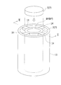
- FIG. 1 is a perspective view of a metal member and a resin member to be joined by a joining apparatus according to the present invention.
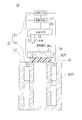
- FIG. 2 is a cross-sectional view taken along the line II-II shown in FIG. 1, and is an explanatory view for explaining the configuration of the joining apparatus according to the present invention.
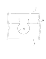
- FIG. 3 is an explanatory view for explaining a joined state between the metal member and the resin member joined by the joining apparatus according to the present invention.
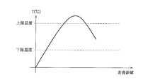
- FIG. 4 is a graph of the temperature of the metal member measured by the temperature measuring means in the joining apparatus according to the present invention.
- FIG. 5 is a graph of the temperature of the metal member measured by the temperature measuring means in the joining apparatus according to the present invention.
- FIG. 6 is a graph of the temperature of the metal member measured by the temperature measuring means in the joining apparatus according to the present invention.
- FIG. 7 is a graph of the temperature of the metal member measured by the temperature measuring means in the joining apparatus according to the present invention.
- FIG. 8 is a graph of the temperature of the metal member measured by the temperature measuring means in the joining apparatus according to the present invention.
- FIG. 9 is a graph of the temperature of the metal member measured by the temperature measuring means in the joining apparatus according to the present invention.
- the bonding inspection apparatus according to the present invention is incorporated in the bonding apparatus according to the present invention, the description of the embodiment of the bonding apparatus is replaced with the description of the bonding inspection apparatus according to the present invention.
- this embodiment demonstrates the aspect in which the joining test
- FIG. 1 is a perspective view of a metal member and a resin member to be joined by a joining device
- FIG. 2 is a cross-sectional view taken along the line II-II shown in FIG. 1 and an explanation for explaining the configuration of the joining device according to the present invention
- FIG. 3 and FIG. 3 are explanatory views for explaining a joined state between the metal member and the resin member.
- the joining device 10 includes a joining inspection device 11 and a joining laser 12 for laser joining the metal member 2 and the resin member 3.
- the bonding apparatus 10 may be provided with a pressing plate 16 for pressing the bonding region BF when a metal member 2 and a resin member 3 described later are bonded.
- the pressing plate 16 is preferably made of a material that transmits laser light emitted from the bonding laser 12 and is preferably glass.
- a joining inspection apparatus 11 is an apparatus for inspecting a joining state of a joining structure in which a metal member 2 and a resin member 3 are joined in a joining region BF, and a jig 13 that can accommodate the metal member 2. And a temperature measuring means 14 and a judging means 15.
- the metal member 2 has a cylindrical shape.
- an iron metal, a stainless steel metal, a copper metal, an aluminum metal, a magnesium metal, and alloys thereof can be cited.
- a metal molding may be sufficient and zinc die-casting, aluminum die-casting, powder metallurgy, etc. may be sufficient.
- the shape of the metal member 2 is not limited to the cylindrical shape.
- the metal member 2 is provided with a bonding region BF to be bonded to the resin member 3.
- the joining region BF of the present embodiment is an upper end surface of the metal member 2 and an annular region.
- a concave portion 21 having an opening may be formed in the metal member 2 in the bonding region BF (see FIG. 3).
- the metal member 2 and the resin member 3 are joined.
- the concave portion 21 may be formed with a protruding portion t protruding inward. In the case where the protruding portion t is formed, the bonding strength between the metal member 2 and the resin member 3 can be increased by the anchor effect by the protruding portion t when the concave portion 21 is filled with the resin member 3.
- the resin member 3 is bonded to the upper side of the metal member 2 and has a disk shape.
- the resin member 3 are a thermoplastic resin and a thermosetting resin.
- the thermoplastic resin are PVC (polyvinyl chloride), PS (polystyrene), AS (acrylonitrile / styrene), ABS (acrylonitrile). ⁇ Butadiene styrene, PMMA (polymethyl methacrylate), PE (polyethylene), PP (polypropylene), PC (polycarbonate), m-PPE (modified polyphenylene ether), PA6 (polyamide 6), PA66 (polyamide 66), POM (Polyacetal), PET (polyethylene terephthalate), PBT (polybutylene terephthalate), PSF (polysulfone), PAR (polyarylate), PEI (polyetherimide), PPS (polyphenylene sulfide), PES (polyether) Tersulfone
- TPE thermoplastic elastomer
- examples of TPE include TPO (olefin-based), TPS (styrene-based), TPEE (ester-based), TPU (urethane-based), TPA (nylon-based), And TPVC (vinyl chloride type) is mentioned.
- thermosetting resins examples include EP (epoxy), PUR (polyurethane), UF (urea formaldehyde), MF (melamine formaldehyde), PF (phenol formaldehyde), UP (unsaturated polyester), and SI (silicone). Is mentioned. Further, it may be FRP (fiber reinforced plastic).
- a filler may be added to the above-described thermoplastic resin and thermosetting resin.
- the filler include inorganic fillers (glass fibers, inorganic salts, etc.), metal fillers, organic fillers, and carbon fibers.
- the resin member 3 is preferably made of a material that transmits laser light when irradiated with laser light from above the resin member 3 as described later, and the laser transmittance is 15% or more when the thickness is 3 mm. It is preferable that On the other hand, when irradiating the laser beam from below the resin member 3, the resin member 3 may not have laser transparency.
- the temperature measuring means 14 measures the temperature in the vicinity of the joining region BF of the metal member 2 and is provided with one or a plurality. In the case where a plurality of temperature measuring means 14 are provided, the temperature variation of the metal member 2 can be measured by measuring the temperature of the metal member 2 at a different position. In the present embodiment, four contact-type temperature sensors are arranged at equal intervals with respect to the side peripheral surface of the metal member 2 (see FIGS. 1 and 2). As the temperature measuring means 14, a non-contact temperature sensor may be used instead of the contact temperature sensor.
- the contact temperature sensor examples include a thermocouple method, a resistance temperature detector method, a thermistor method, and a bimetal method.
- a non-contact-type temperature sensor the radiation thermometer which measures the infrared radiation of the metal member 2 is mentioned, for example.
- a contact temperature sensor may be used.
- the determination unit 15 determines that the bonding state is good when the actually measured temperatures measured by the temperature measuring units 14 are within a reference temperature range set in advance so that the bonding state between the metal member 2 and the resin member 3 is normal. judge.
- the reference temperature range for determining that the bonding state is good will be described later.
- the bonding laser 12 is used to laser-bond the metal member 2 and the resin member 3, and the type of laser is selected from a fiber laser, a YAG laser, a YVO 4 laser, a semiconductor laser, a carbon dioxide gas laser, and an excimer laser.
- the bonding apparatus 10 may include scanning means 12a that scans the laser beam from the bonding laser 12 a plurality of times along the same locus.
- the bonding laser 12 is scanned along the annular bonding region BF.
- this scanning means 12a since the scanning of the bonding laser 12 can be performed a plurality of times along the same locus, the metal member 2 can be effectively heated, and the resin member 3 in contact with the metal member 2 can be removed. The resin member 3 and the metal member 2 can be efficiently joined by melting.
- the scanning means 12a is a means for using a galvano mirror that reflects the laser light from the bonding laser 12 along the annular bonding area BF, or by moving the jig 13 itself along the annular bonding area BF. Means for relatively changing the positions of 12 and the metal member 2 is also included. That is, the laser beam emitted from the bonding laser 12 whose position is fixed may be scanned using a galvano mirror, or may be scanned by moving the jig 13.
- the bonding apparatus 10 includes a control unit 17 that controls at least one of the output of the scanning unit 12a or the bonding laser 12 based on the determination result of the determination unit 15, and a display that displays whether the bonding state is good or bad. Means (not shown) may be provided.
- control means 17 based on the result of the determination process described later, it is determined that the bonding state is good in the control for changing the scanning speed of the scanning means 12a, the control for changing the output of the bonding laser 12, and the determination process. In such a case, it is possible to perform control to end scanning.
- FIGS. . 4 to 9 are graphs of the temperature of the metal member measured by the temperature measuring means in the bonding inspection apparatus.
- inspection method based on this invention is equipped with the temperature measurement process which measures the temperature of the metal member 2, and the determination process which determines a joining state.
- the bonding state is determined to be good when the actually measured temperature measured in the temperature measurement step is within a preset reference temperature range in which the bonding state between the metal member 2 and the resin member 3 is normal.
- the reference temperature range is set in advance using the same metal member 2 ′ and resin member 3 ′ as the metal member 2 and resin member 3 used in the joint structure to be manufactured before performing the joint inspection method.
- a method for setting the reference temperature range will be described.
- the same metal member 2 ′ as the metal member 2 used in the bonding structure described later is set on the jig 13 of the above-described bonding inspection apparatus 11 (see FIGS. 1 and 2). Thereafter, the four contact-type temperature sensors (temperature measuring means 14) are brought into contact with the side peripheral surface in the vicinity of the bonding region BF ′ in the metal member 2 ′ at equal intervals.
- laser light is irradiated from the bonding laser 12 disposed above the resin member 3 ′ toward the resin member 3 ′.
- the temperature of the metal member 2 ′ is monitored by a contact temperature sensor (temperature measuring means 14) in contact with the metal member 2 ′.
- the output of the laser beam irradiated from the bonding laser 12 is changed, and when the temperature of the metal member 2 ′ reaches a predetermined temperature, the output from the bonding laser 12 is stopped, and the metal member 2 ′ and the resin are stopped.
- the joining state with the member 3 ′ is evaluated.
- the evaluation of the joining state at this time is performed by a generally known water resistance test (for example, an IP67 test, an air leak test, a strength test, a water resistance test, and a fracture observation of the joint surface).
- the above-described evaluation of the joined state is repeated by raising the temperature of the metal member 2 ′.
- the temperature of the metal member 2 ′ is increased by about 10 ° C. from 223 ° C. Evaluate.
- the temperature of the metal member 2 ′ is increased to perform the bonding evaluation.
- the temperature of the metal member 2 ′ shows 303 ° C.
- bubbles pyrolysis gas
- the temperature measured by the temperature measuring means 14 when the thermal decomposition is confirmed on the resin member 3 ′ is set as the measured thermal decomposition temperature and set to the upper limit value of the reference temperature range.
- the reference temperature range is set by the above method. In addition, since the measurement of this reference temperature range changes with materials and shapes of metal member 2 'or resin member 3', it is performed for every joining structure manufactured.
- the method of manufacturing a joining structure is determined, determining the quality of the joining state of the resin member 3 and the metal member 2 in the junction structure actually manufactured.
- the metal member 2 is set on the jig 13 of the bonding inspection apparatus 11 described above. Thereafter, four contact-type temperature sensors (temperature measuring means 14) are brought into contact with the side peripheral surface of the metal member 2 in the vicinity of the bonding region BF at equal intervals (see FIGS. 1 and 2).
- the resin member 3 used for the joint structure to be manufactured is brought into contact with the metal member 2 from above, and the resin member 3 is pressed against the metal member 2 by the pressing plate 16 of the bonding inspection apparatus 11 (see FIG. 2). ).
- the lower limit value of the reference temperature range is set to 283 ° C., which is the actual melting temperature of the resin member 3, and the upper limit value of the reference temperature range is
- the measured thermal decomposition temperature of the resin member 3 is set to 303 ° C.
- the measured melting temperature and measured pyrolysis temperature of the resin member 3 are values previously measured by the above method using the same material and the same shape of the metal member 2 ′ and the resin member 3 ′.
- the laser beam is irradiated from the bonding laser 12 disposed above the resin member 3 toward the resin member 3, and the metal member is detected by the contact-type temperature sensor (temperature measurement means 14) that is in contact with the metal member 2. 2 is monitored (temperature measurement step).
- the bonding laser 12 is scanned along the bonding region BF by the scanning unit 12a.
- FIG. 1 a graph showing the relationship between the scanning distance of the bonding laser 12 and the temperature of the metal member 2 measured by one temperature measuring unit 14 when the bonding laser 12 is scanned once by the scanning unit 12a is shown in FIG. This is shown in FIG.
- the bonding laser 12 is scanned by the scanning unit 12 a, and the temperature of the metal member 2 rises until the bonding laser 12 passes near the contact temperature sensor (temperature measurement unit 14). To do. Then, as the temperature reaches the peak and the bonding laser 12 moves away from the contact-type temperature sensor (temperature measurement means 14), the amount of heat accumulated in the metal member 2 diffuses and the temperature drops.
- the determination unit 15 determines that the joining state between the metal member 2 and the resin member 3 is good. In other words, whether the joining state is good or bad is determined depending on whether or not the peak value of the temperature of the metal member 2 measured by the temperature measuring unit 14 is included in a preset reference temperature range. The joining state is determined.
- the determination of the bonding state described above is a determination result of the bonding state based on one temperature measurement unit 14. However, in the determination result of the bonding state based on the plurality of temperature measurement units 14, all the temperature measurement units 14 measure. When the peak value of the temperature to be included is included in the reference temperature range, the bonding state is determined to be good.
- the peak value of the temperature exceeds the upper limit value of the reference temperature range, and thermal decomposition occurs in the resin member 3, so that the bonding state between the metal member 2 and the resin member 3 is poor. Is determined. Further, in the graph of FIG. 6, the temperature peak value is lower than the lower limit value of the reference temperature range, and the resin member 3 is not thermally melted. Therefore, the bonding state between the metal member 2 and the resin member 3 is determined to be defective. To do.
- the temperature of the metal member 2 in the vicinity of the joining region BF is measured by the temperature measuring means 14 and the temperature of the metal member 2 is within the reference temperature range. Whether or not the joining state between the metal member 2 and the resin member 3 is acceptable can be determined.
- the temperature measuring means 14 can The bonding state can be determined while monitoring the temperature.
- the temperature variation of the metal member 2 can be measured, so that it is included in the reference temperature range when determining the joining state between the metal member 2 and the resin member 3. You can identify the position that is not. Thereby, the position of the bonding failure can be specified.
- this embodiment demonstrated the form which joins the resin member 3 and the metal member 2 by irradiating a laser beam toward the resin member 3 from the joining laser 12 arrange
- a joining laser may be disposed below the metal member, and laser light may be irradiated from the metal member side.
- the bonding state between the metal member 2 and the resin member 3 is determined only by scanning the bonding laser 12 once by the scanning unit 12a.
- the metal member 2 is scanned by the bonding laser 12 a plurality of times.
- the quality of the bonded state between the resin member 3 and the resin member 3 may be determined.
- the bonding laser 12 is scanned three times, the quality of the bonded state between the metal member 2 and the resin member 3 may be determined.
- examples of FIGS. 7 to 9 will be described as graphs of temperature after the bonding laser 12 is scanned three times.
- the bonding laser 12 is scanned three times by the scanning means 12a.
- the determination unit 15 determines that the joining state between the metal member 2 and the resin member 3 is good.
- the determination unit 15 determines that the joining state between the metal member 2 and the resin member 3 is good in the first scan, and therefore, based on the determination result, the control unit 15 performs the control. While the output of the bonding laser 12 is stopped by the means 17, the scanning of the bonding laser 12 may be terminated and the second scanning may not be performed.
- the determination means. 15 determines that the bonding state between the metal member 2 and the resin member 3 is defective.
- the graph of FIG. 9 shows that the temperature of the peak value of the junction laser 12 is lower than the lower limit value of the reference temperature range due to the first scan of the junction laser 12. Since the temperature peak value is included in the reference temperature range by scanning, the determination unit 15 determines that the joining state between the metal member 2 and the resin member 3 is good.
- the control means 17 may perform control for increasing the speed, control for slowing the scanning of the bonding laser 12 with respect to the scanning means 12a to accumulate heat in the metal member 2, control for increasing the number of times of laser scanning, and the like.
- control unit 17 controls the bonding laser 12 and the scanning unit 12a based on the determination result, thereby efficiently controlling the temperature of the metal member 2 and bonding the metal member 2 and the resin member 3 together. it can.
Landscapes
- Engineering & Computer Science (AREA)
- Mechanical Engineering (AREA)
- Physics & Mathematics (AREA)
- Optics & Photonics (AREA)
- Electromagnetism (AREA)
- Thermal Sciences (AREA)
- Plasma & Fusion (AREA)
- Toxicology (AREA)
- Health & Medical Sciences (AREA)
- Chemical & Material Sciences (AREA)
- Chemical Kinetics & Catalysis (AREA)
- General Chemical & Material Sciences (AREA)
- Oil, Petroleum & Natural Gas (AREA)
- Lining Or Joining Of Plastics Or The Like (AREA)
- Laser Beam Processing (AREA)
Abstract
金属部材(2,2')と樹脂部材(3,3')とが接合領域(BF,BF')で接合された接合構造体の接合状態を検査する接合検査装置(11)であって、金属部材(2,2')の温度を計測する温度計測手段(14)と、温度計測手段(14)で計測した実測温度が、予め設定された金属部材(2,2')と樹脂部材(3,3')との接合状態を正常とする基準温度範囲内である場合に、接合状態を良好と判定する判定手段(15)と、を備えている。
Description
本発明は、接合検査装置及び接合装置並びに接合検査方法に関する。
従来から、対峙された被溶接部材の上方からレーザ光を照射して互いに接合し、その溶接品質を検査するレーザ溶接品質の検査方法が記載された文献として、特許文献1が知られている。
具体的には、被溶接部材のレーザ照射面に低融点材料が被覆されており、被溶接部材がレーザ照射されることにより低融点材料が溶融し、この低融点材料の溶融長や溶融面積をカメラ等の撮像手段により撮像し、この撮像手段によって得られた画像データを演算することによって、レーザ溶接の品質を検査する方法が開示されている。
特許文献1に開示された検査方法は、撮像手段によって得られた画像データからレーザ溶接の品質を検査するため、例えば、金属部材と樹脂部材との接合面を撮像して接合状態の良否を判断するには不向きであった。
すなわち、被溶接部材が互いに透明材料である場合は、被溶接部材同士の接合面を上方から撮像手段によって撮像することが可能であるが、被溶接部材が互いに不透明材料の場合は、接合面を視認することができず、撮像手段によって接合面を撮像することができなかった。
本発明は、かかる点に鑑みてなされたものであり、その目的とするところは、撮像手段による外観検査によらないで、接合状態の良否を判定できる接合検査装置及び接合装置並びに接合検査方法を提供することにある。
上記目的を達するために、本発明は次のとおりの構成としている。
本発明に係る接合検査装置は、金属部材と樹脂部材とが接合領域で接合された接合構造体の接合状態を検査する接合検査装置であって、前記金属部材の温度を計測する温度計測手段と、前記温度計測手段で計測した実測温度が、予め設定された前記金属部材と前記樹脂部材との接合状態を正常とする基準温度範囲内である場合に、前記接合状態を良好と判定する判定手段と、を備えていることを特徴とする。
また、上記接合検査装置であって、前記基準温度範囲は、下限値を、前記樹脂部材の実測溶融温度とし、上限値を、前記樹脂部材の実測熱分解温度としてもよい。
また、本発明に係る接合装置は、上記接合検査装置と、前記金属部材と前記樹脂部材とをレーザ接合させるレーザと、が備えられていることを特徴とする。
また、上記接合装置であって、さらに、前記レーザを同一軌跡で複数回走査させる走査手段が備えられていてもよい。
また、上記接合装置であって、さらに、前記判定手段の判定結果に基づいて、前記走査手段又は前記レーザの出力の少なくとも一方を制御する制御部が備えられていてもよい。
また、本発明に係る接合検査方法は、金属部材と樹脂部材とが接合領域で接合された接合構造体の接合状態を検査する接合検査方法であって、前記金属部材の温度を計測する温度計測工程と、前記温度計測工程で計測した実測温度が、予め設定された前記金属部材と前記樹脂部材との接合状態を正常とする基準温度範囲内である場合に、前記接合状態を良好と判定する判定工程と、を備えていることを特徴とする。
また、上記接合検査方法であって、前記基準温度範囲は、下限値を、前記樹脂部材の実測溶融温度とし、上限値を、前記樹脂部材の実測熱分解温度としてもよい。
本発明によれば、撮像手段による外観検査によらないで、接合状態の良否を判定できる接合検査装置及び接合装置並びに接合検査方法を提供できる。
以下、本発明に係る接合検査装置及び接合装置並びに接合検査方法の実施形態について、説明する。
なお、本発明に係る接合検査装置は、本発明に係る接合装置に組み込まれているので、接合装置の実施形態の説明を以って、本発明に係る接合検査装置の説明に代える。なお、本実施形態では、接合装置に接合検査装置が組み込まれている態様を説明するが、接合検査装置単体で使用してもよい。
[接合装置及び接合検査装置の説明]
以下、本発明に係る接合装置について図1~3を参照しながら説明する。図1は、接合装置によって接合される金属部材及び樹脂部材の斜視図、図2は、図1に示すII-II 線に沿う断面を示すとともに、本発明に係る接合装置の構成を説明する説明図、図3は、金属部材と樹脂部材との接合状態を説明する説明図である。
以下、本発明に係る接合装置について図1~3を参照しながら説明する。図1は、接合装置によって接合される金属部材及び樹脂部材の斜視図、図2は、図1に示すII-II 線に沿う断面を示すとともに、本発明に係る接合装置の構成を説明する説明図、図3は、金属部材と樹脂部材との接合状態を説明する説明図である。
本発明に係る接合装置10は、接合検査装置11と、金属部材2と樹脂部材3とをレーザ接合させる接合レーザ12とが備えられている。なお、接合装置10には、後述する金属部材2と樹脂部材3との接合時に、接合領域BFに押圧をかけるための押圧板16が設けられていてもよい。この押圧板16は、接合レーザ12が出射するレーザ光を透過する材料が好ましく、ガラスであることが好ましい。
本発明に係る接合検査装置11は、金属部材2と樹脂部材3とが接合領域BFで接合された接合構造体の接合状態を検査する装置であって、金属部材2を収容可能な治具13と、温度計測手段14と、判定手段15と、を備えている。
金属部材2は円筒形状である。金属部材2の一例としては、鉄系金属、ステンレス系金属、銅系金属、アルミ系金属、マグネシウム系金属、および、それらの合金が挙げられる。また、金属成型体であってもよく、亜鉛ダイカスト、アルミダイカスト、粉末冶金などであってもよい。なお、金属部材2の形状は、円筒形状に限られるものではない。
金属部材2には、樹脂部材3と接合される接合領域BFが備えられている。本実施形態の接合領域BFは、金属部材2の上端面であり環状の領域である。
接合領域BFにおける金属部材2には、開口を有する凹状部21が形成されていてもよい(図3参照)。この凹状部21に樹脂部材3が充填されることにより金属部材2と樹脂部材3とが接合される。また、凹状部21には、内側に突出する突出部tが形成されていてもよい。突出部tが形成されている場合は、凹状部21に樹脂部材3が充填されると、突出部tによるアンカー効果によって金属部材2と樹脂部材3との接合強度を高めることができる。
樹脂部材3は、金属部材2の上方に接合されるものであり、円盤形状である。樹脂部材3の一例としては、熱可塑性樹脂、および熱硬化性樹脂であり、熱可塑性樹脂の一例としては、PVC(ポリ塩化ビニル)、PS(ポリスチレン)、AS(アクリロニトリル・スチレン)、ABS(アクリロニトリル・ブタジエン・スチレン)、PMMA(ポリメチルメタクリレート)、PE(ポリエチレン)、PP(ポリプロピレン)、PC(ポリカーボネート)、m-PPE(変性ポリフェニレンエーテル)、PA6(ポリアミド6)、PA66(ポリアミド66)、POM(ポリアセタール)、PET(ポリエチレンテレフタレート)、PBT(ポリブチレンテレフタレート)、PSF(ポリサルホン)、PAR(ポリアリレート)、PEI(ポリエーテルイミド)、PPS(ポリフェニレンサルファイド)、PES(ポリエーテルサルホン)、PEEK(ポリエーテルエーテルケトン)、PAI(ポリアミドイミド)、LCP(液晶ポリマー)、PVDC(ポリ塩化ビニリデン)、PTFE(ポリテトラフルオロエチレン)、PCTFE(ポリクロロトリフルオロエチレン)、および、PVDF(ポリフッ化ビニリデン)が挙げられる。また、TPE(熱可塑性エラストマ)であってもよく、TPEの一例としては、TPO(オレフィン系)、TPS(スチレン系)、TPEE(エステル系)、TPU(ウレタン系)、TPA(ナイロン系)、および、TPVC(塩化ビニル系)が挙げられる。
熱硬化性樹脂の一例としては、EP(エポキシ)、PUR(ポリウレタン)、UF(ユリアホルムアルデヒド)、MF(メラミンホルムアルデヒド)、PF(フェノールホルムアルデヒド)、UP(不飽和ポリエステル)、および、SI(シリコーン)が挙げられる。また、FRP(繊維強化プラスチック)であってもよい。
なお、上記した熱可塑性樹脂および熱硬化性樹脂には、充填剤が添加されていてもよい。充填剤の一例としては、無機系充填剤(ガラス繊維、無機塩類など)、金属系充填剤、有機系充填剤、および、炭素繊維などが挙げられる。
また、樹脂部材3は、後述するような、樹脂部材3の上方からレーザ光を照射する場合は、レーザ光を透過する材料が好ましく、そのレーザ透過率は、厚みが3mmのときに15%以上であることが好ましい。一方、樹脂部材3の下方からレーザ光を照射する場合は、樹脂部材3はレーザ透過性を有していなくてもよい。
温度計測手段14は、金属部材2の接合領域BF近傍の温度を計測するものであり、1個又は複数個備えられている。温度計測手段14が複数備えられている場合は、各温度計測手段14がそれぞれ異なる位置の金属部材2の温度を計測することにより、金属部材2の温度バラツキについても計測することができる。本実施形態では、金属部材2の側周面に対して等間隔に4つの接触式温度センサが配置されている(図1及び2参照)。なお、温度計測手段14としては、接触式温度センサに代えて非接触式温度センサを用いてもよい。
接触式温度センサとしては、例えば、熱電対方式、測温抵抗体方式、サーミスタ方式、バイメタル方式などが挙げられる。非接触式温度センサとしては、例えば、金属部材2の赤外線放射を計測する放射温度計が挙げられる。なお、金属部材2の温度を精度よく計測するためには、接触式温度センサを用いるとよい。
判定手段15は、各温度計測手段14でそれぞれ計測した実測温度が、予め設定され金属部材2と樹脂部材3との接合状態を正常とする基準温度範囲内である場合に、接合状態を良好と判定する。なお、接合状態を良好と判定するための基準温度範囲については、後述する。
接合レーザ12は、金属部材2と樹脂部材3とをレーザ接合させるものであり、レーザの種類としては、ファイバレーザ、YAGレーザ、YVO4レーザ、半導体レーザ、炭酸ガスレーザ、エキシマレーザの中から選択される。
さらに、接合装置10は、接合レーザ12からのレーザ光を同一軌跡で複数回走査させる走査手段12aが備えられていてもよい。本実施形態の走査手段12aでは、環状の接合領域BFに沿って接合レーザ12を走査させる。この走査手段12aによれば、接合レーザ12の走査を同一軌跡で複数回行うことができるため、金属部材2を効果的に加熱することができ、金属部材2と接触している樹脂部材3を溶融させて効率よく樹脂部材3と金属部材2とを接合させることができる。
なお、走査手段12aは、環状の接合領域BFに沿って接合レーザ12からのレーザ光を反射させるガルバノミラーを用いる手段や、治具13自体を環状の接合領域BFに沿って動かして、接合レーザ12と金属部材2との位置を相対的に変化させる手段も含まれるものとする。すなわち、位置が固定された接合レーザ12から出射されたレーザ光を、ガルバノミラーを用いて走査してもよいし、治具13を移動させることによって走査してもよい。
接合装置10には、上述した構成の他に、判定手段15の判定結果に基づいて走査手段12a又は接合レーザ12の出力の少なくとも一方を制御する制御手段17や、接合状態の良否を表示する表示手段(不図示)が備えられていてもよい。
この制御手段17によれば、後述する判定工程の結果に基づいて、走査手段12aの走査速度を変更させる制御や、接合レーザ12の出力を変更させる制御や、判定工程において接合状態が良好と判断された場合に走査を終了させる制御等を行うことができる。
[接合検査方法の説明]
次に、上述した接合装置10及び接合検査装置11を用いた、金属部材2と樹脂部材3とが接合された接合構造体における接合状態の検査方法について、図4~9を参照しながら説明する。図4~9は、接合検査装置における温度計測手段が計測する金属部材の温度のグラフである。
次に、上述した接合装置10及び接合検査装置11を用いた、金属部材2と樹脂部材3とが接合された接合構造体における接合状態の検査方法について、図4~9を参照しながら説明する。図4~9は、接合検査装置における温度計測手段が計測する金属部材の温度のグラフである。
・接合検査方法の概要
本発明に係る接合検査方法は、金属部材2の温度を計測する温度計測工程と、接合状態を判定する判定工程と、を備える。判定工程では、温度計測工程で計測した実測温度が、予め設定された金属部材2と樹脂部材3との接合状態が正常である基準温度範囲内である場合に、接合状態を良好と判定する。
本発明に係る接合検査方法は、金属部材2の温度を計測する温度計測工程と、接合状態を判定する判定工程と、を備える。判定工程では、温度計測工程で計測した実測温度が、予め設定された金属部材2と樹脂部材3との接合状態が正常である基準温度範囲内である場合に、接合状態を良好と判定する。
・基準温度範囲について
まず初めに、基準温度範囲の設定について説明する。基準温度範囲は、接合検査方法を行う前に、予め、製造する接合構造体に使われる金属部材2及び樹脂部材3と同一の金属部材2´及び樹脂部材3´を用いて設定される。以下、基準温度範囲の設定手法を説明する。
まず初めに、基準温度範囲の設定について説明する。基準温度範囲は、接合検査方法を行う前に、予め、製造する接合構造体に使われる金属部材2及び樹脂部材3と同一の金属部材2´及び樹脂部材3´を用いて設定される。以下、基準温度範囲の設定手法を説明する。
まず、上述した接合検査装置11の治具13に、後述の接合構造体に使われる金属部材2と同一の金属部材2´をセットする(図1及び2参照)。その後、4つの接触式温度センサ(温度計測手段14)を等間隔に金属部材2´における接合領域BF´近傍の側周面に接触させる。
次に、金属部材2´の上方から、製造する接合構造体に使われる樹脂部材3と同一の樹脂部材3´を接触させ、接合装置10の押圧板16によって樹脂部材3´を金属部材2´に向けて押圧させる(図2参照)。
次に、樹脂部材3´の上方に配置された接合レーザ12から、樹脂部材3´に向けてレーザ光を照射する。これとともに、金属部材2´に接触されている接触式温度センサ(温度計測手段14)によって金属部材2´の温度をモニタリングする。そして、接合レーザ12から照射されるレーザ光の出力を変化させ、金属部材2´の温度が、所定の温度となったときに、接合レーザ12からの出力を止めて、金属部材2´と樹脂部材3´との接合状態を評価する。このときの接合状態の評価は、一般的に知られている耐水試験(例えば、IP67試験、エアリーク試験、強度試験、耐水試験、接合面の破断観測)によって行われる。
上述した一連の接合状態の評価を金属部材2´の温度を上昇させて繰り返し行う。一例として、金属部材2´にアルミを用い、樹脂部材3´にPBTを用いる場合であれば、金属部材2´の温度を223℃から10℃ずつ程度上昇させていき、各温度で接合状態の評価を行う。
ここで、金属部材2´にアルミを用い、樹脂部材3´にPBTを用いた場合は、金属部材2´の温度が283℃を示したときの接合評価によって、PBTの溶融が確認された。この樹脂部材3´が溶融したときの温度計測手段14によって計測された温度を実測溶融温度とし、基準温度範囲の下限値に設定する。
さらに、金属部材2´の温度を上昇させて接合評価を行っていき、金属部材2´の温度が303℃を示したときに、PBTと金属部材との接合領域に気泡(熱分解ガス)が確認され熱分解が生じた。このように樹脂部材3´に熱分解が確認されたときの温度計測手段14によって計測された温度を実測熱分解温度とし、基準温度範囲の上限値に設定する。
以上の手法によって、基準温度範囲が設定される。なお、この基準温度範囲の測定は、金属部材2´又は樹脂部材3´の材料や形状によって異なるため、製造される接合構造体毎に行われる。
・接合状態の良否判定について
次に、実際に製造される接合構造体において、樹脂部材3と金属部材2との接合状態の良否を判定しながら接合構造体を製造する方法について説明する。
次に、実際に製造される接合構造体において、樹脂部材3と金属部材2との接合状態の良否を判定しながら接合構造体を製造する方法について説明する。
まず、上述した接合検査装置11の治具13に、金属部材2をセットする。その後、4つの接触式温度センサ(温度計測手段14)を等間隔に接合領域BF近傍の金属部材2の側周面に接触させる(図1及び図2参照)。
次に、金属部材2の上方から、製造する接合構造体に使われる樹脂部材3を接触させ、接合検査装置11の押圧板16によって樹脂部材3を金属部材2に向けて押圧させる(図2参照)。
次に、前述した基準温度範囲を設定する。一例として金属部材2にアルミを用い、樹脂部材3にPBTを用いた場合、基準温度範囲の下限値は、樹脂部材3の実測溶融温度である283℃と設定され、基準温度範囲の上限値は、樹脂部材3の実測熱分解温度である303℃と設定される。なお、樹脂部材3の実測溶融温度及び実測熱分解温度は、同一材料及び同一形状の金属部材2´及び樹脂部材3´を用いて上記手法によって予め測定した値である。
次に、樹脂部材3の上方に配置された接合レーザ12から樹脂部材3に向けてレーザ光を照射するとともに、金属部材2に接触されている接触式温度センサ(温度計測手段14)によって金属部材2の温度をモニタリングする(温度計測工程)。このとき、接合レーザ12は、走査手段12aにより接合領域BFに沿って走査される。
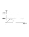
ここで、接合レーザ12を走査手段12aによって1回走査させたときに1つの温度計測手段14が計測した、接合レーザ12の走査距離と、金属部材2の温度との関係を示すグラフを図4~図6に示す。
図4のグラフによれば、走査手段12aによって接合レーザ12を走査していき、接合レーザ12が接触式温度センサ(温度計測手段14)の近傍を通過するまでは、金属部材2の温度が上昇する。そして、温度のピークを迎え、接合レーザ12が、接触式温度センサ(温度計測手段14)から遠ざかるにつれて、金属部材2に蓄積された熱量が拡散して温度が下降する。
このとき図4のグラフでは、温度のピーク値が基準温度範囲の下限値(PBTの場合283℃)から、基準温度範囲の上限値(PBTの場合303℃)までの間に含まれている。従って、判定工程において判定手段15は、金属部材2と樹脂部材3との接合状態を良好と判定する。すなわち、接合状態の良否判定としては、温度計測手段14が計測する金属部材2の温度のピーク値が、予め設定された基準温度範囲に含まれているか否かによって、金属部材2と樹脂部材3との接合状態を判定する。
上述した接合状態の判定は、1つの温度計測手段14に基づいた接合状態の判定結果であるが、複数の温度計測手段14に基づいた接合状態の判定結果では、全ての温度計測手段14が計測する温度のピーク値が基準温度範囲に含まれている場合に接合状態を良好と判定する。
一方で、図5のグラフでは、温度のピーク値が基準温度範囲の上限値を上回っており、樹脂部材3に熱分解が起きているので、金属部材2と樹脂部材3との接合状態を不良と判定する。また、図6のグラフでは、温度のピーク値が基準温度範囲の下限値を下回っており、樹脂部材3が熱溶融されていないので、金属部材2と樹脂部材3との接合状態を不良と判定する。
以上説明したとおり、本発明に係る接合検査方法によれば、温度計測手段14によって、接合領域BF付近の金属部材2の温度を測定して、金属部材2の温度が基準温度範囲内であるか否かによって金属部材2と樹脂部材3との接合状態の良否を判定することができる。
さらに、本発明に係る接合検査方法によれば、基準温度範囲の上限値と下限値との間が比較的狭い樹脂部材3を接合させる場合であっても、温度計測手段14によって金属部材2の温度をモニタリングしながら接合状態を判定することができる。
さらに、温度計測手段14が複数備えられている場合は、金属部材2の温度バラツキを計測することができるので、金属部材2と樹脂部材3との接合状態の判定時に、基準温度範囲に含まれていない位置を特定できる。これにより、接合不良の位置を特定することができる。
なお、本実施形態では、樹脂部材3の上方に配置された接合レーザ12から樹脂部材3に向けてレーザ光を照射して樹脂部材3と金属部材2とを接合する形態について説明したが、この変形例として、金属部材の厚みが薄い場合等は、接合レーザを金属部材の下方に配置させて、金属部材側からレーザ光を照射してもよい。
[他の実施形態]
ところで、上記実施形態では、走査手段12aによって接合レーザ12を1回走査しただけで、金属部材2と樹脂部材3との接合状態を判定したが、接合レーザ12を複数回走査して金属部材2と樹脂部材3との接合状態の良否を判定してもよい。
ところで、上記実施形態では、走査手段12aによって接合レーザ12を1回走査しただけで、金属部材2と樹脂部材3との接合状態を判定したが、接合レーザ12を複数回走査して金属部材2と樹脂部材3との接合状態の良否を判定してもよい。
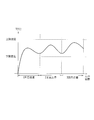
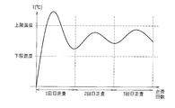
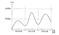
例えば、接合レーザ12を3回走査させた後に、金属部材2と樹脂部材3との接合状態の良否を判定してもよい。以下、接合レーザ12を3回走査させた後の温度のグラフとして図7~9の例を説明する。
図7のグラフでは、走査手段12aによって接合レーザ12を3回走査している。この例では、3回とも温度のピーク値が基準温度範囲内に含まれているので、判定手段15は、金属部材2と樹脂部材3との接合状態を良好と判定する。
なお、上述の図7のグラフの例において、判定手段15は、1回目の走査で金属部材2と樹脂部材3との接合状態を良好と判定しているので、この判定結果に基づいて、制御手段17により、接合レーザ12の出力を停止するとともに、接合レーザ12の走査を終了させて2回目の走査を行わない制御を行ってもよい。
他のグラフの例として、図8のグラフは、1回目の接合レーザ12の走査により、温度のピーク値が基準温度範囲の上限値を超えている。従って、樹脂部材3には気泡が発生して分解が生じているので、例え2回目及び3回目の接合レーザ12の走査によって温度のピーク値が基準温度範囲内に含まれていても、判定手段15は、金属部材2と樹脂部材3との接合状態を不良と判定する。
他のグラフの例として、図9のグラフは、1回目の接合レーザ12の走査により、温度のピーク値が基準温度範囲の下限値を下回っているが、2回目及び3回目の接合レーザ12の走査によって温度のピーク値が基準温度範囲内に含まれているので、判定手段15は、金属部材2と樹脂部材3との接合状態を良好と判定する。
このとき、図9のグラフの例において、1回目の接合レーザ12の走査により基準温度範囲の下限値に達していない判定結果に基づいて、2回目の接合レーザ12の走査における接合レーザ12の出力を上げる制御や、走査手段12aに対して接合レーザ12の走査を遅くして金属部材2に蓄熱させる制御や、レーザの走査回数を増やす制御等を制御手段17が行ってもよい。
このように、制御手段17が判定結果に基づいて接合レーザ12や走査手段12aを制御することにより、効率よく金属部材2の温度を制御して金属部材2と樹脂部材3とを接合することができる。
なお、上記に示した本発明の実施形態は本発明を具体化した例であって、本発明の技術的範囲を限定する性格のものではない。
10 接合装置
11 接合検査装置
12 接合レーザ
12a 走査手段
13 治具
14 温度計測手段
15 判定手段
16 押圧板
17 制御手段
2、2´ 金属部材
21 凹状部
3、3´ 樹脂部材
t 突出部
BF、BF´ 接合領域
11 接合検査装置
12 接合レーザ
12a 走査手段
13 治具
14 温度計測手段
15 判定手段
16 押圧板
17 制御手段
2、2´ 金属部材
21 凹状部
3、3´ 樹脂部材
t 突出部
BF、BF´ 接合領域
Claims (7)
- 金属部材と樹脂部材とが接合領域で接合された接合構造体の接合状態を検査する接合検査装置であって、
前記金属部材の温度を計測する温度計測手段と、
前記温度計測手段で計測した実測温度が、予め設定された前記金属部材と前記樹脂部材との接合状態を正常とする基準温度範囲内である場合に、前記接合状態を良好と判定する判定手段と、
を備えていることを特徴とする接合検査装置。 - 請求項1に記載された接合検査装置であって、
前記基準温度範囲は、
下限値を、前記樹脂部材の実測溶融温度とし、
上限値を、前記樹脂部材の実測熱分解温度とすること
を特徴とする接合検査装置。 - 請求項1又は2に記載された接合検査装置と、
前記金属部材と前記樹脂部材とをレーザ接合させるレーザと、
が備えられていることを特徴とする接合装置。 - 請求項3に記載された接合装置であって、
さらに、前記レーザを同一軌跡で複数回走査させる走査手段が備えられていることを特徴とする接合装置。 - 請求項4に記載された接合装置であって、
さらに、前記判定手段の判定結果に基づいて、前記走査手段又は前記レーザの出力の少なくとも一方を制御する制御部が備えられていることを特徴とする接合装置。 - 金属部材と樹脂部材とが接合領域で接合された接合構造体の接合状態を検査する接合検査方法であって、
前記金属部材の温度を計測する温度計測工程と、
前記温度計測工程で計測した実測温度が、予め設定された前記金属部材と前記樹脂部材との接合状態を正常とする基準温度範囲内である場合に、前記接合状態を良好と判定する判定工程と、
を備えていることを特徴とする接合検査方法。 - 請求項6に記載された接合検査方法であって、
前記基準温度範囲は、
下限値を、前記樹脂部材の実測溶融温度とし、
上限値を、前記樹脂部材の実測熱分解温度とすること
を特徴とする接合検査方法。
Applications Claiming Priority (2)
| Application Number | Priority Date | Filing Date | Title |
|---|---|---|---|
| JP2015-042165 | 2015-03-04 | ||
| JP2015042165A JP2016159343A (ja) | 2015-03-04 | 2015-03-04 | 接合検査装置及び接合装置並びに接合検査方法 |
Publications (1)
| Publication Number | Publication Date |
|---|---|
| WO2016140098A1 true WO2016140098A1 (ja) | 2016-09-09 |
Family
ID=56843895
Family Applications (1)
| Application Number | Title | Priority Date | Filing Date |
|---|---|---|---|
| PCT/JP2016/055102 Ceased WO2016140098A1 (ja) | 2015-03-04 | 2016-02-22 | 接合検査装置及び接合装置並びに接合検査方法 |
Country Status (2)
| Country | Link |
|---|---|
| JP (1) | JP2016159343A (ja) |
| WO (1) | WO2016140098A1 (ja) |
Cited By (1)
| Publication number | Priority date | Publication date | Assignee | Title |
|---|---|---|---|---|
| CN120232937A (zh) * | 2025-03-03 | 2025-07-01 | 盐城东创精密制造有限公司 | 基于自然对流冷却的部件接合程度热阻测试方法 |
Citations (3)
| Publication number | Priority date | Publication date | Assignee | Title |
|---|---|---|---|---|
| JP2004122560A (ja) * | 2002-10-02 | 2004-04-22 | Toyota Motor Corp | 樹脂材の溶着方法および樹脂材の溶着装置 |
| JP2005007415A (ja) * | 2003-06-17 | 2005-01-13 | Hamamatsu Photonics Kk | レーザ溶接における品質管理方法 |
| JP2010046831A (ja) * | 2008-08-19 | 2010-03-04 | Toyota Motor Corp | 樹脂と金属との接合方法および装置 |
-
2015
- 2015-03-04 JP JP2015042165A patent/JP2016159343A/ja active Pending
-
2016
- 2016-02-22 WO PCT/JP2016/055102 patent/WO2016140098A1/ja not_active Ceased
Patent Citations (3)
| Publication number | Priority date | Publication date | Assignee | Title |
|---|---|---|---|---|
| JP2004122560A (ja) * | 2002-10-02 | 2004-04-22 | Toyota Motor Corp | 樹脂材の溶着方法および樹脂材の溶着装置 |
| JP2005007415A (ja) * | 2003-06-17 | 2005-01-13 | Hamamatsu Photonics Kk | レーザ溶接における品質管理方法 |
| JP2010046831A (ja) * | 2008-08-19 | 2010-03-04 | Toyota Motor Corp | 樹脂と金属との接合方法および装置 |
Cited By (1)
| Publication number | Priority date | Publication date | Assignee | Title |
|---|---|---|---|---|
| CN120232937A (zh) * | 2025-03-03 | 2025-07-01 | 盐城东创精密制造有限公司 | 基于自然对流冷却的部件接合程度热阻测试方法 |
Also Published As
| Publication number | Publication date |
|---|---|
| JP2016159343A (ja) | 2016-09-05 |
Similar Documents
| Publication | Publication Date | Title |
|---|---|---|
| US7268866B2 (en) | Method for inspecting a weld seam in a workpiece made of weldable plastic and device for carrying out this method | |
| US11590578B2 (en) | Internal defect detection system, three-dimensional additive manufacturing device, internal defect detection method, method of manufacturing three-dimensional additive manufactured product, and three-dimensional | |
| US8541746B2 (en) | Process and system for the nondestructive quality determination of a weld seam, and a welding device | |
| TWI627052B (zh) | 接合結構體的製造方法及接合結構體 | |
| US20130343947A1 (en) | Method and device for process monitoring | |
| Kim et al. | Non-destructive identification of weld-boundary and porosity formation during laser transmission welding by using optical coherence tomography | |
| JP6724543B2 (ja) | レーザ光吸収率測定方法、レーザ光吸収率測定装置及びレーザ加工方法 | |
| US11958255B2 (en) | In-situ fiber-optic temperature field measurement during thermoplastic composite welding and other applications | |
| CN107683409A (zh) | 取向鉴定装置、取向鉴定方法和分布鉴定装置 | |
| KR100955564B1 (ko) | 수지재의 용착 방법 및 용착 장치 | |
| JP4577103B2 (ja) | レーザ溶着良否判定方法及びその装置 | |
| US9354211B2 (en) | Method of testing a weld between two plastic parts | |
| JP2016159343A (ja) | 接合検査装置及び接合装置並びに接合検査方法 | |
| US9772295B2 (en) | Laying head, fibre placement device and method | |
| Kraemer et al. | Quality control in the production process of SMC lightweight material | |
| EP2796857A1 (en) | Optical non-destructive inspection apparatus and optical non-destructive inspection method | |
| US10935502B2 (en) | Directed energy and sensing for detection of inconsistencies in laminates | |
| JP4858454B2 (ja) | レーザ溶着部品の製造方法 | |
| JP2012103176A (ja) | 検査装置 | |
| JP5445174B2 (ja) | 高分子材料の超音波接合方法およびその装置 | |
| JP2004122560A (ja) | 樹脂材の溶着方法および樹脂材の溶着装置 | |
| WO2016157588A1 (ja) | 非破壊検査装置及び非破壊検査方法 | |
| Dittmar et al. | Temperature monitoring independent of laser-beam-position during laser transmission welding of fibre reinforced thermoplastics | |
| JP2016147279A (ja) | 検査装置及びレーザ加工装置並びにレーザ加工検査方法 | |
| KR101461072B1 (ko) | 풍력블레이드의 접착면 검사장치, 검사방법 및 검사 시스템 |
Legal Events
| Date | Code | Title | Description |
|---|---|---|---|
| 121 | Ep: the epo has been informed by wipo that ep was designated in this application |
Ref document number: 16758792 Country of ref document: EP Kind code of ref document: A1 |
|
| NENP | Non-entry into the national phase |
Ref country code: DE |
|
| 122 | Ep: pct application non-entry in european phase |
Ref document number: 16758792 Country of ref document: EP Kind code of ref document: A1 |