WO2016140004A1 - ワイヤレス送電装置、異物検出方法、充電器 - Google Patents
ワイヤレス送電装置、異物検出方法、充電器 Download PDFInfo
- Publication number
- WO2016140004A1 WO2016140004A1 PCT/JP2016/053042 JP2016053042W WO2016140004A1 WO 2016140004 A1 WO2016140004 A1 WO 2016140004A1 JP 2016053042 W JP2016053042 W JP 2016053042W WO 2016140004 A1 WO2016140004 A1 WO 2016140004A1
- Authority
- WO
- WIPO (PCT)
- Prior art keywords
- current
- wireless power
- bridge circuit
- power transmission
- foreign object
- Prior art date
- Legal status (The legal status is an assumption and is not a legal conclusion. Google has not performed a legal analysis and makes no representation as to the accuracy of the status listed.)
- Ceased
Links
Images





Classifications
-
- H—ELECTRICITY
- H02—GENERATION; CONVERSION OR DISTRIBUTION OF ELECTRIC POWER
- H02J—ELECTRIC POWER NETWORKS; CIRCUIT ARRANGEMENTS OR SYSTEMS FOR SUPPLYING OR DISTRIBUTING ELECTRIC POWER; SYSTEMS FOR STORING ELECTRIC ENERGY
- H02J50/00—Circuit arrangements or systems for wireless supply or distribution of electric power
- H02J50/60—Circuit arrangements or systems for wireless supply or distribution of electric power responsive to the presence of foreign objects, e.g. detection of living beings
-
- G—PHYSICS
- G01—MEASURING; TESTING
- G01V—GEOPHYSICS; GRAVITATIONAL MEASUREMENTS; DETECTING MASSES OR OBJECTS; TAGS
- G01V3/00—Electric or magnetic prospecting or detecting; Measuring magnetic field characteristics of the earth, e.g. declination, deviation
- G01V3/02—Electric or magnetic prospecting or detecting; Measuring magnetic field characteristics of the earth, e.g. declination, deviation operating with propagation of electric current
-
- H—ELECTRICITY
- H02—GENERATION; CONVERSION OR DISTRIBUTION OF ELECTRIC POWER
- H02J—ELECTRIC POWER NETWORKS; CIRCUIT ARRANGEMENTS OR SYSTEMS FOR SUPPLYING OR DISTRIBUTING ELECTRIC POWER; SYSTEMS FOR STORING ELECTRIC ENERGY
- H02J50/00—Circuit arrangements or systems for wireless supply or distribution of electric power
- H02J50/10—Circuit arrangements or systems for wireless supply or distribution of electric power using inductive coupling
- H02J50/12—Circuit arrangements or systems for wireless supply or distribution of electric power using inductive coupling of the resonant type
-
- H—ELECTRICITY
- H04—ELECTRIC COMMUNICATION TECHNIQUE
- H04B—TRANSMISSION
- H04B5/00—Near-field transmission systems, e.g. inductive or capacitive transmission systems
- H04B5/20—Near-field transmission systems, e.g. inductive or capacitive transmission systems characterised by the transmission technique; characterised by the transmission medium
- H04B5/24—Inductive coupling
- H04B5/26—Inductive coupling using coils
- H04B5/266—One coil at each side, e.g. with primary and secondary coils
-
- H—ELECTRICITY
- H04—ELECTRIC COMMUNICATION TECHNIQUE
- H04B—TRANSMISSION
- H04B5/00—Near-field transmission systems, e.g. inductive or capacitive transmission systems
- H04B5/70—Near-field transmission systems, e.g. inductive or capacitive transmission systems specially adapted for specific purposes
- H04B5/79—Near-field transmission systems, e.g. inductive or capacitive transmission systems specially adapted for specific purposes for data transfer in combination with power transfer
Definitions
- the present invention relates to wireless power feeding technology, and more particularly to foreign object detection.
- Wireless power supply based on the Qi standard uses electromagnetic induction between the transmission coil and the reception coil.
- the power feeding system includes a power feeding device having a transmission coil and a power receiving terminal having a receiving coil.
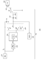
- FIG. 1 is a diagram showing a configuration of a wireless power feeding system 10 compliant with the Qi standard.
- the power feeding system 10 includes a power transmission device 20 (TX, Power Transmitter) and a power receiving device 30 (RX, Power Receiver).
- the power receiving device 30 is mounted on an electronic device such as a mobile phone terminal, a smart phone, an audio player, a game device, or a tablet terminal.
- the power transmission device 20 includes a transmission coil (primary coil) 22, a driver 24, a controller 26, and a demodulator 28.
- the driver 24 includes an H-bridge circuit (full-bridge circuit) or a half-bridge circuit, applies a drive signal S 1, specifically a pulse signal, to the transmission coil 22, and causes the transmission coil 22 to drive the transmission coil 22 by a drive current flowing through the transmission coil 22.
- An electromagnetic field power signal S2 is generated.
- the controller 26 controls the power transmission device 20 as a whole. Specifically, the controller 26 changes the transmission power by controlling the switching frequency of the driver 24 or the switching duty ratio.
- a communication protocol is defined between the power transmission device 20 and the power reception device 30, and information can be transmitted from the power reception device 30 to the power transmission device 20 using the control signal S3.
- the control signal S3 is transmitted from the reception coil 32 (secondary coil) to the transmission coil 22 in a form of AM (Amplitude Modulation) modulation using Backscatter modulation.
- the control signal S3 includes, for example, power control data (also referred to as a packet) for controlling the amount of power supplied to the power receiving device 30, data indicating unique information of the power receiving device 30, and the like.
- the demodulator 28 demodulates the control signal S3 included in the current or voltage of the transmission coil 22.
- the controller 26 controls the driver 24 based on the power control data included in the demodulated control signal S3.
- the power receiving device 30 includes a receiving coil 32, a rectifying circuit 34, a smoothing capacitor 36, a modulator 38, a load 40, a controller 42, and a power supply circuit 44.
- the reception coil 32 receives the power signal S ⁇ b> 2 from the transmission coil 22 and transmits a control signal S ⁇ b> 3 to the transmission coil 22.
- the rectifier circuit 34 and the smoothing capacitor 36 rectify and smooth the current S4 induced in the receiving coil 32 in accordance with the power signal S2, and convert it into a DC voltage.
- the power supply circuit 44 uses a power supplied from the power transmission device 20 to charge a secondary battery (not shown), or boosts or steps down the DC voltage V RECT and supplies it to the controller 42 and other loads 40.
- the controller 42 monitors the power supplied to the load 40 and generates power control data for controlling the amount of power supplied from the power transmission device 20 accordingly.
- the modulator 38 modulates the coil current and the coil voltage of the transmission coil 22 by modulating the control signal S3 including the power control data and modulating the coil current of the reception coil 32.
- the power transmitted by the power transmitting device 200 and the power received by the power receiving device 300 are compared, and when a mismatch exceeding the allowable value occurs between them, it is determined that a foreign object exists. .
- JP 2013-38854 A Japanese Patent No. 5071574
- the present invention has been made in view of such problems, and one of exemplary purposes of an aspect thereof is to provide a power transmission device capable of detecting foreign matter.
- An aspect of the present invention relates to a wireless power transmission apparatus that transmits a power signal to a wireless power reception apparatus.
- a wireless power transmission apparatus includes a transmission antenna including a resonance capacitor and a transmission coil connected in series, a driver including a bridge circuit that applies a driving voltage to the transmission antenna, a current sensor that detects a current flowing in the bridge circuit, and a bridge circuit A foreign substance detector that detects a current flowing in the bridge circuit while changing the switching frequency of the first and second parts and determines the presence or absence of a foreign substance based on the result.
- the frequency characteristics of the current flowing through the bridge circuit for example, the center frequency giving the peak and the bandwidth change according to the situation around the transmitting antenna 201
- the frequency characteristics of the current flowing through the bridge circuit can be detected. Can be detected.
- the circuit configuration of the foreign object detector can be significantly simplified as compared with the conventional case, and the cost can be reduced.
- the foreign object detector may determine the presence / absence of a foreign object based on the frequency f 0 at which the current peaks and the frequency f 1 when the current decreases by a predetermined ratio from the peak.
- the foreign object detector (i) obtains the frequency f 0 and the current value I MAX at that time while sweeping up the switching frequency f SW of the bridge circuit, starting from a frequency lower than the resonance frequency of the transmitting antenna, and (iii) ) Calculate the current I LOW obtained by multiplying the current value I MAX by a predetermined ratio, and (iii) obtain the frequency f 1 when the detected current becomes the current I LOW while sweeping up the switching frequency f SW Also good.
- the predetermined ratio may be 1 / ⁇ 2.
- the foreign object detector may receive a threshold value from the wireless power receiving apparatus.
- the current sensor may detect a current flowing from the DC power supply to the upper power supply terminal of the bridge circuit.
- the accuracy can be improved. This effect is particularly remarkable when a smoothing capacitor is connected to the upper power supply terminal of the bridge circuit.
- the current sensor may detect a current flowing from the lower power supply terminal of the bridge circuit to the ground. In this case, since the current can be measured as a signal close to direct current, the accuracy can be improved.
- the current sensor is a detection resistor provided on the current path to be detected, a sense amplifier that amplifies the voltage drop of the detection resistor, a low-pass filter that receives the output of the sense amplifier, and converts the output of the low-pass filter into a digital value An A / D converter.
- the current sensor may be shared with a current detection circuit that detects a current necessary for calculating transmission power. In this case, additional hardware can be further reduced.
- the wireless power transmission device may conform to the Qi standard.
- the charger includes any of the wireless power transmission devices described above.
- foreign matter can be detected.
- FIG. 1 It is a figure which shows the structure of the wireless electric power feeding system based on Qi specification. It is a block diagram of an electric power feeding system provided with the wireless power transmission apparatus which concerns on embodiment. It is a diagram showing a relationship between the switching frequency f SW and the current I S of the bridge circuit. It is a flowchart which shows an example of a foreign material detection sequence. It is a circuit diagram which shows the structural example of a power transmission apparatus. It is an operation
- the state in which the member A is connected to the member B means that the member A and the member B are electrically connected to each other in addition to the case where the member A and the member B are physically directly connected. It includes cases where the connection is indirectly made through other members that do not substantially affect the general connection state, or that do not impair the functions and effects achieved by their combination.
- the state in which the member C is provided between the member A and the member B refers to the case where the member A and the member C or the member B and the member C are directly connected, as well as their electric It includes cases where the connection is indirectly made through other members that do not substantially affect the general connection state, or that do not impair the functions and effects achieved by their combination.
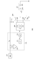
- FIG. 2 is a block diagram of a power feeding system 100 including the wireless power transmission device according to the embodiment.
- the power feeding system 100 includes a power transmission device 200 (TX, Power Transmitter) and a power receiving device 300 (RX, Power Receiver).
- the power receiving device 300 is mounted on an electronic device such as a mobile phone terminal, a smart phone, an audio player, a game device, or a tablet terminal.
- the power transmission device 200 is mounted on a charger having a charging stand, for example.
- the power transmission device 200 includes a transmission coil (primary coil) 202, a driver 204, a controller 206, a demodulator 208, a DC power supply 210, and a current sensor 220.
- the driver 204 includes an H-bridge circuit (full-bridge circuit) or a half-bridge circuit, and applies a drive signal S 1, specifically a pulse signal, to the transmission coil 202.
- An electromagnetic field power signal S2 is generated.
- a half bridge circuit 205 is used.
- the upper power supply terminal P1 of the half bridge circuit 205 is supplied with the power supply voltage V DD from the DC power supply 210, and the lower power supply terminal P2 is grounded.
- a smoothing capacitor CS is connected to the upper power supply terminal P1.
- the controller 206 controls the power transmission apparatus 200 as a whole. Specifically, the controller 206 changes the transmission power by controlling the switching frequency f SW of the driver 204 or the switching duty ratio.
- the controller 206 since what is necessary is just to use a well-known technique except the thing regarding the foreign material detector 230 mentioned later, description is abbreviate
- a communication protocol is defined between the power transmission device 200 and the power reception device 300, and information can be transmitted from the power reception device 300 to the power transmission device 200 using the control signal S3.
- This control signal S3 is transmitted from the reception coil 302 (secondary coil) to the transmission coil 202 in the form of AM (Amplitude Modulation) modulation using backscatter modulation.
- the control signal S3 includes, for example, power control data (also referred to as a packet) for controlling the amount of power supplied to the power receiving apparatus 300, data indicating information unique to the power receiving apparatus 300, and the like.
- the control signal S3 may include a threshold value that defines an appropriate range of the Q value of the transmission antenna 201.
- the demodulator 208 demodulates the control signal S3 included in the current or voltage of the transmission coil 202.
- the controller 206 controls the driver 204 based on the power control data included in the demodulated control signal S3.
- the power transmission device 200 includes a current sensor 220 and a foreign object detector (Foreign Object Detector) 230 of the controller 206.
- FOD foreign object detection
- the Current sensor 220 detects a current I S flowing through the bridge circuit 205 generates a current detection value S4 for indicating the detected amount of current.
- the detected current value S4 is input to the foreign object detector 230 of the controller 206.
- the “current flowing through the bridge circuit” includes an input current of the bridge circuit or a current flowing through one of the arms, and does not include an output current, that is, a coil current flowing through the antenna.
- the input current of the bridge circuit includes a current flowing into the upper power supply terminal of the bridge circuit 205 and a current flowing out from the lower power supply terminal.
- Foreign object detector 230 specifically determines the presence or absence of a foreign object by detecting the current I S flowing through the bridge circuit 205 while changing the switching frequency f SW of the bridge circuit 205, based on the result.
- the above is the basic configuration of the power transmission device 200. Next, the principle and operation of the foreign object detector 230 will be described.
- FIG. 3 is a diagram illustrating the relationship between the switching frequency f SW of the bridge circuit 205 and the current I S.
- the present inventors have revealed that examined switching frequency dependence of the current I S flowing through the bridge circuit 205, for example, center frequency f 0 which gives a peak I MAX, (that the frequency characteristic) bandwidth ⁇ f is, around the transmitting antenna 201 It came to recognize that it changes according to the situation.
- the current sensor 220 detects the frequency characteristic of the current I S flowing through the bridge circuit 205, by monitoring the change in the frequency characteristics, it is possible to detect the foreign matter.
- the frequency f 0 of the current I S reaches the peak I MAX, a predetermined ratio from the current I MAX peak I MAX 1 / ⁇ 2, and the frequency f 1 when the reduced, based on, foreign substances It is desirable to determine the presence or absence.
- a foreign object may be detected based on the Q value of the transmission antenna 201.
- FIG. 4 is a flowchart illustrating an example of the foreign object detection sequence.
- a predetermined frequency f S lower than the resonance frequency f R of the transmitting antenna 201 is used as a start frequency, and the switching frequency f SW is swept up.
- the frequency f 0 and the current value I MAX at that time are acquired (S102).
- a current I LOW obtained by multiplying the peak current value I MAX by a predetermined ratio 1 / ⁇ 2 is calculated (S104).
- sweeping up (iii) further the switching frequency f SW it acquires a frequency f 1 at which the detected current I S reaches the calculated current I LOW (S106), and calculates the Q value (S108).
- the foreign object detector 230 determines the presence or absence of a foreign object based on the Q value obtained in this way (S110). More specifically, the foreign object detector 230 can determine the presence or absence of a foreign object based on the comparison result between the calculated Q value and a predetermined threshold value. Here, the foreign object detector 230 may receive a predetermined threshold value from the wireless power receiving apparatus. The above is the flow of foreign object detection.
- FIG. 5 is a circuit diagram illustrating a configuration example of the power transmission device 200.
- the current sensor 220 (referred to the input current) current flowing from the DC power supply 210 to the upper power supply terminal P1 of the bridge circuit 205 as a detection target I S.
- the current sensor 220 includes a detection resistor R S provided on the path of the current I S to be detected, a sense amplifier 222 that amplifies the voltage drop V S of the detection resistor R S , and a low-pass filter that receives the output of the sense amplifier 222 224 and an A / D converter 226 that converts the output of the low-pass filter 224 into a digital value.
- the upper power terminal P1 is connected to the smoothing capacitor C S, therefore the current sensor 220 can also be understood as being measured current I S flowing into the smoothing capacitor C S.
- the detection target input current I S which is advantageous from the viewpoint of protection operation.
- the power transmission device 200 often has a function of calculating its own transmission power, and the conventional power transmission device also includes a circuit for current detection for power calculation.
- the current sensor 220 can be shared (utilized) with a current detection circuit for power calculation.
- FIG. 6 is an operation waveform diagram of the power transmission device 200 of FIG. FIG. 6 shows a current I COIL flowing through the transmission antenna 201, an input current I S to the bridge circuit 205, and an output signal S 5 from the low-pass filter 224.
- the input current I S corresponds to the coil current I COIL during the period when the high-side transistor of the bridge circuit 205 is on
- the input current I S has a half waveform, but the upper power supply terminal of the bridge circuit 205 the P1 (the output of the DC power supply 210)
- the capacitor C S for smoothing is connected, the input current I S has a DC component corresponding to the amplitude of the coil current I cOIL, according to the switching frequency f SW AC Sum of ingredients.
- the DC component that is, the coil current I COIL can be detected by removing the AC component corresponding to the switching frequency f SW by the low-pass filter 224.
- FIG. 7 is a circuit diagram of a charger 400 including the power transmission device 200.
- the charger 400 charges the electronic device 500 including the power receiving device 300.
- the charger 400 includes a housing 402, a charging stand 404, and a circuit board 406.
- the electronic device to be fed is placed on the charging stand 404.
- the driver 204, the controller 206, and other circuit components are mounted on the circuit board 406.
- the transmission antenna 201 is laid out immediately below the charging stand 404.
- the charger 400 may receive a DC voltage from the AC / DC converter 410 or may incorporate an AC / DC converter. Alternatively, the charger 400 may be supplied with DC power from the outside via a bus including a power supply line such as USB (Universal Serial Bus).
- USB Universal Serial Bus
- Current at which the current sensor 220 monitors is not limited to the input current I S of the bridge circuit.
- the detection resistor RS may be inserted on the ground side with respect to the bridge circuit 205.
- additional circuitry and signal processing is required.
- the output current that is, the coil current I COIL
- the circuit configuration and the signal processing can be simplified can be enjoyed.
- the on resistance of the switching transistor (high side transistor or low side transistor) of the bridge circuit 205 may be used instead of inserting the detection resistor RS .
- the output current (that is, the coil current I COIL ) of the bridge circuit 205 is measured, the merit that the circuit configuration and the signal processing can be simplified can be enjoyed.
- DESCRIPTION OF SYMBOLS 100 Power feeding system, 200, TX ... Power transmission apparatus, 201 ... Transmitting antenna, 202 ... Transmitting coil, 204 ... Driver, 205 ... Bridge circuit, 206 ... Controller, 208 ... Demodulator, 210 ... DC power supply, 220 ... Current sensor, 222, sense amplifier, 224, low-pass filter, 226, A / D converter, 230, foreign object detector, 300, RX, power receiving device, 302, receiving coil, S1, drive signal, S2, power signal, S3, control signal, S4 ... Current detection value, 400 ... Charger, 402 ... Housing, 404 ... Charging stand, 406 ... Circuit board, 500 ... Electronic equipment.
- the present invention can be used for wireless power feeding technology.
Landscapes
- Engineering & Computer Science (AREA)
- Computer Networks & Wireless Communication (AREA)
- Power Engineering (AREA)
- Signal Processing (AREA)
- Life Sciences & Earth Sciences (AREA)
- Geology (AREA)
- General Life Sciences & Earth Sciences (AREA)
- General Physics & Mathematics (AREA)
- Geophysics (AREA)
- Physics & Mathematics (AREA)
- Remote Sensing (AREA)
- Environmental & Geological Engineering (AREA)
- Charge And Discharge Circuits For Batteries Or The Like (AREA)
Abstract
送信アンテナ201は、直列に接続された共振キャパシタおよび送信コイル202を含む。ドライバ204は、送信アンテナ201に駆動電圧を印加するブリッジ回路205を含む。電流センサ220は、ブリッジ回路205に流れる電流ISを検出する。異物検出器230は、ブリッジ回路205のスイッチング周波数を変化させながらブリッジ回路205に流れる電流ISを検出し、その結果にもとづいて異物の有無を判定する。
Description
本発明は、ワイヤレス給電技術に関し、特に異物検出に関する。
近年、電子機器に電力を供給するために、ワイヤレス給電が普及し始めている。異なるメーカーの製品間の相互利用を促進するために、WPC(Wireless Power Consortium)が組織され、WPCにより国際標準規格であるQi(チー)規格が策定された。
Qi規格にもとづいたワイヤレス給電は、送信コイルと受信コイル間の電磁誘導を利用したものである。給電システムは、送信コイルを有する給電装置と、受信コイルを有する受電端末で構成される。
図1は、Qi規格に準拠したワイヤレス給電システム10の構成を示す図である。給電システム10は、送電装置20(TX、Power Transmitter)と受電装置30(RX、Power Receiver)と、を備える。受電装置30は、携帯電話端末、スマートホン、オーディオプレイヤ、ゲーム機器、タブレット端末などの電子機器に搭載される。
送電装置20は、送信コイル(1次コイル)22、ドライバ24、コントローラ26、復調器28を備える。ドライバ24は、Hブリッジ回路(フルブリッジ回路)あるいはハーフブリッジ回路を含み、送信コイル22に駆動信号S1、具体的にはパルス信号を印加し、送信コイル22に流れる駆動電流により、送信コイル22に電磁界の電力信号S2を発生させる。コントローラ26は、送電装置20全体を統括的に制御するものであり、具体的には、ドライバ24のスイッチング周波数、あるいはスイッチングのデューティ比を制御することにより、送信電力を変化させる。
Qi規格では、送電装置20と受電装置30の間で通信プロトコルが定められており、受電装置30から送電装置20に対して、制御信号S3による情報の伝達が可能となっている。この制御信号S3は、後方散乱変調(Backscatter modulation)を利用して、AM(Amplitude Modulation)変調された形で、受信コイル32(2次コイル)から送信コイル22に送信される。この制御信号S3には、たとえば、受電装置30に対する電力供給量を制御する電力制御データ(パケットともいう)、受電装置30の固有の情報を示すデータなどが含まれる。復調器28は、送信コイル22の電流あるいは電圧に含まれる制御信号S3を復調する。コントローラ26は、復調された制御信号S3に含まれる電力制御データにもとづいて、ドライバ24を制御する。
受電装置30は、受信コイル32、整流回路34、平滑コンデンサ36、変調器38、負荷40、コントローラ42、電源回路44を備える。受信コイル32は、送信コイル22からの電力信号S2を受信するとともに、制御信号S3を送信コイル22に対して送信する。整流回路34および平滑コンデンサ36は、電力信号S2に応じて受信コイル32に誘起される電流S4を整流・平滑化し、直流電圧に変換する。
電源回路44は、送電装置20から供給された電力を利用して図示しない二次電池を充電し、あるいは直流電圧VRECTを昇圧あるいは降圧し、コントローラ42やその他の負荷40に供給する。
コントローラ42は、負荷40に供給される電力をモニタし、それに応じて、送電装置20からの電力供給量を制御する電力制御データを生成する。変調器38は、電力制御データを含む制御信号S3を変調し、受信コイル32のコイル電流を変調することにより、送信コイル22のコイル電流およびコイル電圧を変調する。
この給電システム10では、送電装置20と受電端末(電子機器)は、比較的自由な空間に配置されるため、送信コイル22と受信コイル32の間、あるいはその近傍に、金属片などの導電性の異物(Foreign Object)が置かれる状況が生じうる。この状態でワイヤレス給電が行われると、異物に電流が流れ、電力損失が発生してしまう。また異物が発熱するという問題がある。かかる状況に鑑みて、WPC1.1(System Description Wireless Power Transfer Volume I: Low Power Part 1: Interface Definition Version 1.1)仕様において、異物検出(FOD:Foreign Object Detection)が策定された。
このFODでは、送電装置200が送出した電力と、受電装置300が受信した電力と、が比較され、それらの間に許容値を超える不一致が発生した場合に、異物が存在するものと判定される。
現在、中電力向けQi規格(Volume II Middle Power)の策定が進められており、別方式のFOD方式が模索されている。その中のひとつとして、送信コイル(アンテナ)のQ値を利用したものが挙げられる。具体的には、送信コイルに異物が近接すると、送信アンテナのQ値が変化することを利用して、異物の有無を判定しようとするものである。
本発明は係る課題に鑑みてなされたものであり、そのある態様の例示的な目的のひとつは、異物検出可能な送電装置の提供にある。
本発明のある態様は、ワイヤレス受電装置に電力信号を送信するワイヤレス送電装置に関する。ワイヤレス送電装置は、直列に接続された共振キャパシタおよび送信コイルを含む送信アンテナと、送信アンテナに駆動電圧を印加するブリッジ回路を含むドライバと、ブリッジ回路に流れる電流を検出する電流センサと、ブリッジ回路のスイッチング周波数を変化させながらブリッジ回路に流れる電流を検出し、その結果にもとづいて異物の有無を判定する異物検出器と、を備える。
ブリッジ回路に流れる電流の周波数特性、たとえばピークを与えるセンター周波数や、バンド幅は、送信アンテナ201の周囲の状況に応じて変化するため、ブリッジ回路に流れる電流の周波数特性を検出することで、異物を検出できる。この態様によると、異物検出器の回路構成を従来よりも著しく簡略化し、コストを下げることができる。
異物検出器は、電流がピークとなる周波数f0と、電流がピークから所定比率、低下したときの周波数f1と、にもとづいて、異物の有無を判定してもよい。
異物検出器は、(i)送信アンテナの共振周波数より低い周波数をスタートとして、ブリッジ回路のスイッチング周波数fSWをスイープアップしながら、周波数f0およびそのときの電流値IMAXを取得し、(iii)電流値IMAXに所定比率を乗じた電流ILOWを算出し、(iii)さらにスイッチング周波数fSWをスイープアップしながら、検出電流が電流ILOWとなったときの周波数f1を取得してもよい。
所定比率は、1/√2であってもよい。
異物検出器は、Q=f0/(2×|f0-f1|)にしたがいQ値を算出し、算出したQ値と所定のしきい値の比較結果にもとづいて、異物の有無を判定してもよい。
異物検出器は、ワイヤレス受電装置からしきい値を受信してもよい。
電流センサは、DC電源からブリッジ回路の上側電源端子に流入する電流を検出してもよい。
この場合、電流を直流に近い信号として測定できるため、精度を高めることができる。特にブリッジ回路の上側電源端子に平滑キャパシタが接続される場合、この効果は顕著である。
この場合、電流を直流に近い信号として測定できるため、精度を高めることができる。特にブリッジ回路の上側電源端子に平滑キャパシタが接続される場合、この効果は顕著である。
電流センサは、ブリッジ回路の下側電源端子から接地に流出する電流を検出してもよい。
この場合、電流を直流に近い信号として測定できるため、精度を高めることができる。
この場合、電流を直流に近い信号として測定できるため、精度を高めることができる。
電流センサは、検出対象の電流の経路上に設けられた検出抵抗と、検出抵抗の電圧降下を増幅するセンスアンプと、センスアンプの出力を受けるローパスフィルタと、ローパスフィルタの出力をデジタル値に変換するA/Dコンバータと、を含んでもよい。
電流センサは、送信電力を算出するために必要な電流を検出する電流検出回路と共用されてもよい。
この場合、追加のハードウェアをさらに削減できる。
この場合、追加のハードウェアをさらに削減できる。
ワイヤレス送電装置は、Qi規格に準拠してもよい。
本発明の別の態様は、充電器に関する。充電器は、上述のいずれかのワイヤレス送電装置を備える。
なお、以上の構成要素の任意の組み合わせや、本発明の構成要素や表現を、方法、装置、システムなどの間で相互に置換したものもまた、本発明の態様として有効である。
本発明のある態様によれば、異物を検出できる。
以下、本発明を好適な実施の形態をもとに図面を参照しながら説明する。各図面に示される同一または同等の構成要素、部材、処理には、同一の符号を付するものとし、適宜重複した説明は省略する。また、実施の形態は、発明を限定するものではなく例示であって、実施の形態に記述されるすべての特徴やその組み合わせは、必ずしも発明の本質的なものであるとは限らない。
本明細書において、「部材Aが、部材Bと接続された状態」とは、部材Aと部材Bが物理的に直接的に接続される場合のほか、部材Aと部材Bが、それらの電気的な接続状態に実質的な影響を及ぼさない、あるいはそれらの結合により奏される機能や効果を損なわせない、その他の部材を介して間接的に接続される場合も含む。
同様に、「部材Cが、部材Aと部材Bの間に設けられた状態」とは、部材Aと部材C、あるいは部材Bと部材Cが直接的に接続される場合のほか、それらの電気的な接続状態に実質的な影響を及ぼさない、あるいはそれらの結合により奏される機能や効果を損なわせない、その他の部材を介して間接的に接続される場合も含む。
同様に、「部材Cが、部材Aと部材Bの間に設けられた状態」とは、部材Aと部材C、あるいは部材Bと部材Cが直接的に接続される場合のほか、それらの電気的な接続状態に実質的な影響を及ぼさない、あるいはそれらの結合により奏される機能や効果を損なわせない、その他の部材を介して間接的に接続される場合も含む。
図2は、実施の形態に係るワイヤレス送電装置を備える給電システム100のブロック図である。給電システム100は、送電装置200(TX、Power Transmitter)と受電装置300(RX、Power Receiver)と、を備える。受電装置300は、携帯電話端末、スマートホン、オーディオプレイヤ、ゲーム機器、タブレット端末などの電子機器に搭載される。
送電装置200は、たとえば充電台を有する充電器に搭載される。送電装置200は、送信コイル(1次コイル)202、ドライバ204、コントローラ206、復調器208、DC電源210、電流センサ220を備える。
ドライバ204は、Hブリッジ回路(フルブリッジ回路)あるいはハーフブリッジ回路を含み、送信コイル202に駆動信号S1、具体的にはパルス信号を印加し、送信コイル202に流れる駆動電流により、送信コイル202に電磁界の電力信号S2を発生させる。本実施の形態では、ハーフブリッジ回路205が使用される。ハーフブリッジ回路205の上側電源端子P1には、DC電源210からの電源電圧VDDが供給され、下側電源端子P2は接地される。上側電源端子P1には平滑キャパシタCSが接続される。
コントローラ206は、送電装置200全体を統括的に制御するものであり、具体的には、ドライバ204のスイッチング周波数fSW、あるいはスイッチングのデューティ比を制御することにより、送信電力を変化させる。コントローラ206の機能、構成については、後述する異物検出器230に関するものを除いて、公知技術を用いればよいため、説明を省略する。
Qi規格では、送電装置200と受電装置300の間で通信プロトコルが定められており、受電装置300から送電装置200に対して、制御信号S3による情報の伝達が可能となっている。この制御信号S3は、後方散乱変調(Backscatter modulation)を利用して、AM(Amplitude Modulation)変調された形で、受信コイル302(2次コイル)から送信コイル202に送信される。この制御信号S3には、たとえば、受電装置300に対する電力供給量を制御する電力制御データ(パケットともいう)、受電装置300の固有の情報を示すデータなどが含まれる。また制御信号S3には、送信アンテナ201のQ値の適正範囲を規定するしきい値が含まれてもよい。
復調器208は、送信コイル202の電流あるいは電圧に含まれる制御信号S3を復調する。コントローラ206は、復調された制御信号S3に含まれる電力制御データにもとづいて、ドライバ204を制御する。
続いて、送電装置200における異物検出(FOD)について説明する。
FODに関して、送電装置200は、電流センサ220およびコントローラ206の異物検出器(Foreign Object Detector)230を備える。
FODに関して、送電装置200は、電流センサ220およびコントローラ206の異物検出器(Foreign Object Detector)230を備える。
電流センサ220は、ブリッジ回路205に流れる電流ISを検出し、検出した電流量を示す電流検出値S4を生成する。電流検出値S4は、コントローラ206の異物検出器230に入力される。「ブリッジ回路に流れる電流」とは、ブリッジ回路の入力電流もしくは、いずれかのアームに流れる電流を含み、出力電流、すなわちアンテナに流れるコイル電流は含まない。またブリッジ回路の入力電流は、ブリッジ回路205の上側電源端子に流入する電流、下側電源端子から流出する電流を含む。
受電装置300への送電開始前に、以下の異物検出処理を実行する。
具体的には異物検出器230は、ブリッジ回路205のスイッチング周波数fSWを変化させながらブリッジ回路205に流れる電流ISを検出し、その結果にもとづいて異物の有無を判定する。
具体的には異物検出器230は、ブリッジ回路205のスイッチング周波数fSWを変化させながらブリッジ回路205に流れる電流ISを検出し、その結果にもとづいて異物の有無を判定する。
以上が送電装置200の基本構成である。続いて異物検出器230の原理、動作を説明する。
図3は、ブリッジ回路205のスイッチング周波数fSWと電流ISの関係を示す図である。本発明者は、ブリッジ回路205に流れる電流ISのスイッチング周波数依存性について検討したところ、たとえばピークIMAXを与えるセンター周波数f0、バンド幅(周波数特性という)Δfが、送信アンテナ201の周囲の状況に応じて変化することを認識するに至った。
バンド幅Δfは、たとえば電流量ISがピークIMAXから所定比率、低下したときのスイッチング周波数fSWを与える周波数f1を用いて、
Δf=2×|f0-f1| …(1)
で定義される。所定比率は、1/√2、1/2、1/eなどを使用しうるが、電気通信の分野では1/√2を採るのが通常である。
Δf=2×|f0-f1| …(1)
で定義される。所定比率は、1/√2、1/2、1/eなどを使用しうるが、電気通信の分野では1/√2を採るのが通常である。
図2の送電装置200によれば、電流センサ220により、ブリッジ回路205に流れる電流ISの周波数特性を検出し、周波数特性の変化を監視することにより、異物を検出することができる。
この方法によれば、ブリッジ回路205に流れる電流ISを測定すれば足りるため、異物検出器230の回路構成を従来よりも著しく簡略化し、コストを下げることができる。
ここで、センター周波数f0の変動のみでは、異物検出の精度が低い場合もある。そこで異物検出器230は、電流ISがピークIMAXとなる周波数f0と、電流IMAXがピークIMAXから所定比率1/√2、低下したときの周波数f1と、にもとづいて、異物の有無を判定することが望ましい。
Qi規格に準拠した送電装置200においては、送信アンテナ201のQ値にもとづいて、異物を検出してもよい。
Q=I0/Δf=f0/(2×|f0-f1|)
Q=I0/Δf=f0/(2×|f0-f1|)
図4は、異物検出シーケンスの一例を示すフローチャートである。
送信アンテナ201の共振周波数fRより低い所定の周波数fSをスタート周波数とし、スイッチング周波数fSWをスイープアップする。
送信アンテナ201の共振周波数fRより低い所定の周波数fSをスタート周波数とし、スイッチング周波数fSWをスイープアップする。
スイープアップの過程において、周波数f0およびそのときの電流値IMAXを取得する(S102)。続いて、ピーク電流値IMAXに所定比率1/√2を乗じた電流ILOWを算出する(S104)。(iii)さらにスイッチング周波数fSWをスイープアップしながら、検出電流ISが算出した電流ILOWとなったときの周波数f1を取得し(S106)、Q値を算出する(S108)。
異物検出器230はこのように得られたQ値にもとづいて、異物の有無を判定する(S110)。より具体的には異物検出器230は、算出したQ値と所定のしきい値の比較結果にもとづいて、異物の有無を判定することができる。ここで異物検出器230は、所定のしきい値を、ワイヤレス受電装置から受信してもよい。以上が異物検出のフローである。
続いて送電装置200の具体的な構成例を説明する。図5は、送電装置200の構成例を示す回路図である。
電流センサ220は、DC電源210からブリッジ回路205の上側電源端子P1に流入する電流(入力電流という)ISを検出対象とする。電流センサ220は、検出対象の電流ISの経路上に設けられた検出抵抗RSと、検出抵抗RSの電圧降下VSを増幅するセンスアンプ222と、センスアンプ222の出力を受けるローパスフィルタ224と、ローパスフィルタ224の出力をデジタル値に変換するA/Dコンバータ226と、を備える。上側電源端子P1には平滑キャパシタCSが接続されており、したがって電流センサ220は、平滑キャパシタCSに流れ込む電流ISを測定しているものと把握することもできる。入力電流ISを検出対象とすることで、保護動作の観点からも有利である。
送電装置200には、自身の送信電力を算出する機能を具備する場合が多く、従来の送電装置も、電力算出のために電流検出のための回路を備えている。この場合、そこで電流センサ220は、電力算出のための電流検出回路と共用(流用)することができる。
図6は、図5の送電装置200の動作波形図である。図6には、送信アンテナ201に流れる電流ICOILと、ブリッジ回路205への入力電流IS、ローパスフィルタ224の出力信号S5が示される。
理論的には、入力電流ISは、ブリッジ回路205のハイサイドトランジスタがオンの期間のコイル電流ICOILに相当するため、入力電流ISは半波形であるが、ブリッジ回路205の上側電源端子P1(DC電源210の出力)には、平滑用のキャパシタCSが接続されるため、入力電流ISは、コイル電流ICOILの振幅に応じたDC成分と、スイッチング周波数fSWに応じた交流成分の和となる。ローパスフィルタ224によって、スイッチング周波数fSWに応じた交流成分を除去することにより、DC成分、すなわちコイル電流ICOILを検出できる。
理論的には、入力電流ISは、ブリッジ回路205のハイサイドトランジスタがオンの期間のコイル電流ICOILに相当するため、入力電流ISは半波形であるが、ブリッジ回路205の上側電源端子P1(DC電源210の出力)には、平滑用のキャパシタCSが接続されるため、入力電流ISは、コイル電流ICOILの振幅に応じたDC成分と、スイッチング周波数fSWに応じた交流成分の和となる。ローパスフィルタ224によって、スイッチング周波数fSWに応じた交流成分を除去することにより、DC成分、すなわちコイル電流ICOILを検出できる。
続いて送電装置200の用途を説明する。図7は、送電装置200を備える充電器400の回路図である。充電器400は、受電装置300を備える電子機器500を充電する。充電器400は、筐体402、充電台404、回路基板406、を備える。給電対象の電子機器は、充電台404上に載置される。ドライバ204やコントローラ206その他の回路部品は、回路基板406上に実装される。送信アンテナ201は、充電台404の直下にレイアウトされる。充電器400は、AC/DCコンバータ410により直流電圧を受けてもよいし、AC/DCコンバータを内蔵してもよい。あるいは充電器400は、USB(Universal Serial Bus)などの給電線を備えるバスを介して、外部からDC電力の供給を受けてもよい。
実施の形態は例示であり、それらの各構成要素や各処理プロセスの組み合わせにいろいろな変形例が可能なこと、またそうした変形例も本発明の範囲にあることは当業者に理解されるところである。以下、こうした変形例を説明する。
(第1の変形例)
電流センサ220が監視する電流は、ブリッジ回路の入力電流ISには限定されない。たとえばブリッジ回路205よりも接地側に検出抵抗RSを挿入してもよい。ただし、接地側で電流を測定する場合には、平滑キャパシタCSによる電流の平滑化の効果が期待できなないため、追加の回路および信号処理が必要となる場合もある。ただしこの場合であっても、ブリッジ回路205の出力電流(つまりコイル電流ICOIL)を測定する場合に比べれば、回路構成および信号処理を簡略化できるというメリットは享受できる。
電流センサ220が監視する電流は、ブリッジ回路の入力電流ISには限定されない。たとえばブリッジ回路205よりも接地側に検出抵抗RSを挿入してもよい。ただし、接地側で電流を測定する場合には、平滑キャパシタCSによる電流の平滑化の効果が期待できなないため、追加の回路および信号処理が必要となる場合もある。ただしこの場合であっても、ブリッジ回路205の出力電流(つまりコイル電流ICOIL)を測定する場合に比べれば、回路構成および信号処理を簡略化できるというメリットは享受できる。
また、検出抵抗RSを挿入する代わりに、ブリッジ回路205のスイッチングトランジスタ(ハイサイドトランジスタまたはローサイドトランジスタ)のオン抵抗を利用してもよい。ただし、スイッチングトランジスタのオン抵抗を利用する場合、ブリッジ回路の内部電流を測定することになるため、平滑キャパシタCSによる電流の平滑化の効果が期待できず、追加の回路および信号処理が必要となる場合もある。ただしこの場合であっても、ブリッジ回路205の出力電流(つまりコイル電流ICOIL)を測定する場合に比べれば、回路構成および信号処理を簡略化できるというメリットは享受できる。
(第2の変形例)
実施の形態では、ハーフブリッジ回路のドライバ204について説明したが、Hブリッジ回路にも適用可能である。
実施の形態では、ハーフブリッジ回路のドライバ204について説明したが、Hブリッジ回路にも適用可能である。
(第3の変形例)
実施の形態では、Q値にもとづいて異物検出する場合を説明したが、本発明はそれには限定されない。Qi規格以外の、将来策定されるであろう規格においては、Q値によらずに、センター周波数f0や、バンド幅Δfの変化にもとづいて、異物を検出しうる。
実施の形態では、Q値にもとづいて異物検出する場合を説明したが、本発明はそれには限定されない。Qi規格以外の、将来策定されるであろう規格においては、Q値によらずに、センター周波数f0や、バンド幅Δfの変化にもとづいて、異物を検出しうる。
実施の形態にもとづき、具体的な用語を用いて本発明を説明したが、実施の形態は、本発明の原理、応用を示しているにすぎず、実施の形態には、請求の範囲に規定された本発明の思想を逸脱しない範囲において、多くの変形例や配置の変更が認められる。
100…給電システム、200,TX…送電装置、201…送信アンテナ、202…送信コイル、204…ドライバ、205…ブリッジ回路、206…コントローラ、208…復調器、210…DC電源、220…電流センサ、222…センスアンプ、224…ローパスフィルタ、226…A/Dコンバータ、230…異物検出器、300,RX…受電装置、302…受信コイル、S1…駆動信号、S2…電力信号、S3…制御信号、S4…電流検出値、400…充電器、402…筐体、404…充電台、406…回路基板、500…電子機器。
本発明はワイヤレス給電技術に利用できる。
Claims (14)
- ワイヤレス受電装置に電力信号を送信するワイヤレス送電装置であって、
直列に接続された共振キャパシタおよび送信コイルを含む送信アンテナと、
前記送信アンテナに駆動電圧を印加するブリッジ回路を含むドライバと、
前記ブリッジ回路に流れる電流を検出する電流センサと、
前記ブリッジ回路のスイッチング周波数を変化させながら前記ブリッジ回路に流れる前記電流を検出し、その結果にもとづいて異物の有無を判定する異物検出器と、
を備えることを特徴とするワイヤレス送電装置。 - 前記異物検出器は、前記電流がピークとなる周波数f0と、前記電流がピークから所定比率、低下したときの周波数f1と、にもとづいて、異物の有無を判定することを特徴とする請求項1に記載のワイヤレス送電装置。
- 前記異物検出器は、
(i)前記送信アンテナの共振周波数より低い周波数をスタートとして、前記ブリッジ回路のスイッチング周波数をスイープアップしながら、前記周波数f0およびそのときの電流値IMAXを取得し、
(iii)電流値IMAXに前記所定比率を乗じた電流ILOWを算出し、
(iii)さらに前記スイッチング周波数をスイープアップしながら、検出電流が前記電流ILOWとなったときの周波数f1を取得することを特徴とする請求項2に記載のワイヤレス送電装置。 - 前記所定比率は、1/√2であることを特徴とする請求項2または3に記載のワイヤレス送電装置。
- 前記異物検出器は、Q=f0/(2×|f0-f1|)にしたがいQ値を算出し、算出したQ値にもとづいて異物の有無を判定することを特徴とする請求項4に記載のワイヤレス送電装置。
- 前記異物検出器は、算出したQ値と所定のしきい値の比較結果にもとづいて、異物の有無を判定することを特徴とする請求項5に記載のワイヤレス送電装置。
- 前記異物検出器は、前記ワイヤレス受電装置から前記しきい値を受信することを特徴とする請求項6に記載のワイヤレス送電装置。
- 前記電流センサは、DC電源から前記ブリッジ回路の上側電源端子に流入する電流を検出することを特徴とする請求項1から7のいずれかに記載のワイヤレス送電装置。
- 前記ブリッジ回路の上側電源端子に接続された平滑キャパシタをさらに備えることを特徴とする請求項8に記載のワイヤレス送電装置。
- 前記電流センサは、
検出対象の電流の経路上に設けられた検出抵抗と、
前記検出抵抗の電圧降下を増幅するセンスアンプと、
前記センスアンプの出力を受けるローパスフィルタと、
前記ローパスフィルタの出力をデジタル値に変換するA/Dコンバータと、
を含むことを特徴とする請求項1から9のいずれかに記載のワイヤレス送電装置。 - 前記電流センサは、送信電力を算出するために必要な電流を検出する電流検出回路と共用されることを特徴とする請求項1から10のいずれかに記載のワイヤレス送電装置。
- Qi規格に準拠したことを特徴とする請求項1から11のいずれかに記載のワイヤレス送電装置。
- 請求項1から12のいずれかに記載のワイヤレス送電装置を備えることを特徴とする充電器。
- ワイヤレス受電装置における異物検出方法であって、
前記ワイヤレス受電装置は、
直列に接続された共振キャパシタおよび送信コイルを含む送信アンテナと、
前記送信アンテナに駆動電圧を印加するブリッジ回路と、
を含み、
前記異物検出方法は、
前記ブリッジ回路のスイッチング周波数を変化させながら前記ブリッジ回路に流れる電流を検出するステップと、
前記電流がピークとなる周波数f0と、前記電流がピークから所定比率低下したときの周波数f1と、にもとづいて、異物の有無を判定するステップと、
を備えることを特徴とする異物検出方法。
Priority Applications (3)
| Application Number | Priority Date | Filing Date | Title |
|---|---|---|---|
| KR1020177027490A KR20170122246A (ko) | 2015-03-04 | 2016-02-02 | 와이어리스 송전 장치, 이물 검출 방법, 충전기 |
| CN201680012844.5A CN107408847B (zh) | 2015-03-04 | 2016-02-02 | 无线供电装置、异物检测方法、充电器 |
| US15/696,987 US10291078B2 (en) | 2015-03-04 | 2017-09-06 | Wireless power transmitter |
Applications Claiming Priority (2)
| Application Number | Priority Date | Filing Date | Title |
|---|---|---|---|
| JP2015-042687 | 2015-03-04 | ||
| JP2015042687A JP6410641B2 (ja) | 2015-03-04 | 2015-03-04 | ワイヤレス送電装置、異物検出方法、充電器 |
Related Child Applications (1)
| Application Number | Title | Priority Date | Filing Date |
|---|---|---|---|
| US15/696,987 Continuation US10291078B2 (en) | 2015-03-04 | 2017-09-06 | Wireless power transmitter |
Publications (1)
| Publication Number | Publication Date |
|---|---|
| WO2016140004A1 true WO2016140004A1 (ja) | 2016-09-09 |
Family
ID=56847511
Family Applications (1)
| Application Number | Title | Priority Date | Filing Date |
|---|---|---|---|
| PCT/JP2016/053042 Ceased WO2016140004A1 (ja) | 2015-03-04 | 2016-02-02 | ワイヤレス送電装置、異物検出方法、充電器 |
Country Status (5)
| Country | Link |
|---|---|
| US (1) | US10291078B2 (ja) |
| JP (1) | JP6410641B2 (ja) |
| KR (1) | KR20170122246A (ja) |
| CN (1) | CN107408847B (ja) |
| WO (1) | WO2016140004A1 (ja) |
Cited By (2)
| Publication number | Priority date | Publication date | Assignee | Title |
|---|---|---|---|---|
| WO2019045350A3 (ko) * | 2017-09-04 | 2019-04-18 | 엘지이노텍 주식회사 | 무선 전력 송신 방법 및 그를 위한 장치 |
| WO2019083170A1 (ko) * | 2017-10-27 | 2019-05-02 | 엘지이노텍(주) | 무선 전력 송신 장치 |
Families Citing this family (23)
| Publication number | Priority date | Publication date | Assignee | Title |
|---|---|---|---|---|
| KR102605047B1 (ko) * | 2016-12-08 | 2023-11-24 | 엘지이노텍 주식회사 | 무선 충전을 위한 이물질 검출 방법 및 그를 위한 장치 |
| JP6342066B1 (ja) * | 2017-02-08 | 2018-06-13 | 三菱電機エンジニアリング株式会社 | 送電側機器 |
| KR102391649B1 (ko) * | 2017-09-04 | 2022-04-27 | 현대자동차주식회사 | 이물질 검출 방법, 이를 이용하는 무선 전력전송 제어 장치 및 무선 전력전송 장치 |
| JP2019097274A (ja) * | 2017-11-21 | 2019-06-20 | ローム株式会社 | ワイヤレス送電装置、異物検出方法、ワイヤレス充電器 |
| CN108173359B (zh) * | 2018-02-06 | 2024-07-19 | 深圳劲芯微电子有限公司 | 基于q值判别无线充电异物的方法及其电路 |
| KR102509314B1 (ko) * | 2018-05-16 | 2023-03-14 | 엘지이노텍 주식회사 | 무선 전력 전송 제어 방법 및 장치 |
| GB201808844D0 (en) * | 2018-05-30 | 2018-07-11 | Imperial Innovations Ltd | Wireless power transmission system and method |
| CN112868162A (zh) | 2018-05-31 | 2021-05-28 | 鲍尔马特技术有限公司 | 确定q因子的系统和方法 |
| EP3818620A4 (en) * | 2018-07-19 | 2022-03-23 | MediaTek Singapore Pte. Ltd. | Detecting foreign objects in wireless power transfer systems |
| WO2020040475A1 (ko) * | 2018-08-21 | 2020-02-27 | 엘지전자 주식회사 | 무선전력 전송 시스템에서 이물질 검출을 수행하는 장치 및 방법 |
| CN111245107B (zh) * | 2018-11-28 | 2024-03-19 | 集成装置技术公司 | 无线电力传送系统中利用线圈电流感测的增强型异物检测 |
| US11527920B2 (en) | 2018-11-28 | 2022-12-13 | Integrated Device Technology, Inc. | Enhanced foreign object detection with coil current sensing in wireless power transfer systems |
| US11418067B2 (en) | 2018-11-28 | 2022-08-16 | Integrated Device Technology, Inc. | Enhanced foreign object detection with coil current sensing in wireless power transfer systems |
| US11211829B2 (en) | 2018-12-31 | 2021-12-28 | Integrated Device Technology, Inc. | Systems and methods for operation efficiency in wireless power transfer |
| EP3726255B1 (en) * | 2019-04-17 | 2025-08-13 | Mettler-Toledo Safeline Limited | Method for operating a metal detector and metal detector |
| CN110277836B (zh) * | 2019-05-23 | 2021-04-09 | 新纳传感系统有限公司 | 无线功率发射器和无线功率传输系统 |
| CN113258627B (zh) * | 2020-02-12 | 2024-09-03 | 北京小米移动软件有限公司 | 反向充电方法、装置、终端及存储介质 |
| DE112020006434T5 (de) | 2020-03-03 | 2022-10-20 | Microchip Technology Incorporated | Erkennung von objekten mit geringer leistung in drahtlosenmehrspulenladeystemen und zugehörige systeme, verfahren und vorrichtungen |
| CN112737148B (zh) * | 2020-12-23 | 2023-07-14 | 歌尔股份有限公司 | 异物检测电路、无线充电系统及异物检测方法 |
| CN113300487B (zh) * | 2021-05-28 | 2024-07-30 | 伏达半导体(合肥)股份有限公司 | 用于无线电能传输系统的异物检测设备及方法 |
| US20230163635A1 (en) * | 2021-11-19 | 2023-05-25 | Samsung Electronics Co., Ltd. | Wireless power transmission device and operating method of wireless power transmitter |
| WO2025053872A1 (en) * | 2023-09-06 | 2025-03-13 | Microchip Technology Incorporated | Foreign object detection by frequency bandwidth comparison |
| US12519347B2 (en) | 2023-09-06 | 2026-01-06 | Microchip Technology Incorporated | Foreign object detection by frequency bandwidth comparison |
Citations (3)
| Publication number | Priority date | Publication date | Assignee | Title |
|---|---|---|---|---|
| JP2011507481A (ja) * | 2007-12-21 | 2011-03-03 | アクセス ビジネス グループ インターナショナル リミテッド ライアビリティ カンパニー | 誘導電力転送 |
| JP2012005238A (ja) * | 2010-06-17 | 2012-01-05 | Nissan Motor Co Ltd | 非接触給電装置 |
| JP2014187795A (ja) * | 2013-03-22 | 2014-10-02 | Dexerials Corp | 送電装置、送受電装置、受電装置検出方法、受電装置検出プログラム、及び半導体装置 |
Family Cites Families (8)
| Publication number | Priority date | Publication date | Assignee | Title |
|---|---|---|---|---|
| CA2682608A1 (en) | 2007-03-30 | 2008-10-09 | Tioga Pharmaceuticals, Inc. | Kappa-opiate agonists for the treatment of diarrhea-predominant and alternating irritable bowel syndrome |
| JP5071574B1 (ja) | 2011-07-05 | 2012-11-14 | ソニー株式会社 | 検知装置、受電装置、非接触電力伝送システム及び検知方法 |
| JP6035711B2 (ja) * | 2011-07-21 | 2016-11-30 | ソニー株式会社 | 検知装置、受電装置、送電装置、非接触電力伝送システム及び検知方法 |
| JP5893285B2 (ja) | 2011-08-04 | 2016-03-23 | キヤノン株式会社 | 給電装置及びプログラム |
| US9553485B2 (en) * | 2011-10-13 | 2017-01-24 | Integrated Device Technology, Inc. | Apparatus, system, and method for detecting a foreign object in an inductive wireless power transfer system based on input power |
| JP6392550B2 (ja) * | 2014-02-10 | 2018-09-19 | ローム株式会社 | ワイヤレス受電装置およびその制御回路、それを用いた電子機器、異常検出方法 |
| JP6497614B2 (ja) * | 2014-05-26 | 2019-04-10 | パナソニックIpマネジメント株式会社 | 送電装置及び無線電力伝送システム |
| JP6632308B2 (ja) * | 2015-10-13 | 2020-01-22 | ローム株式会社 | ワイヤレス送電装置、その制御回路および制御方法、充電器 |
-
2015
- 2015-03-04 JP JP2015042687A patent/JP6410641B2/ja active Active
-
2016
- 2016-02-02 CN CN201680012844.5A patent/CN107408847B/zh not_active Expired - Fee Related
- 2016-02-02 WO PCT/JP2016/053042 patent/WO2016140004A1/ja not_active Ceased
- 2016-02-02 KR KR1020177027490A patent/KR20170122246A/ko not_active Ceased
-
2017
- 2017-09-06 US US15/696,987 patent/US10291078B2/en active Active
Patent Citations (3)
| Publication number | Priority date | Publication date | Assignee | Title |
|---|---|---|---|---|
| JP2011507481A (ja) * | 2007-12-21 | 2011-03-03 | アクセス ビジネス グループ インターナショナル リミテッド ライアビリティ カンパニー | 誘導電力転送 |
| JP2012005238A (ja) * | 2010-06-17 | 2012-01-05 | Nissan Motor Co Ltd | 非接触給電装置 |
| JP2014187795A (ja) * | 2013-03-22 | 2014-10-02 | Dexerials Corp | 送電装置、送受電装置、受電装置検出方法、受電装置検出プログラム、及び半導体装置 |
Cited By (3)
| Publication number | Priority date | Publication date | Assignee | Title |
|---|---|---|---|---|
| WO2019045350A3 (ko) * | 2017-09-04 | 2019-04-18 | 엘지이노텍 주식회사 | 무선 전력 송신 방법 및 그를 위한 장치 |
| US11056931B2 (en) | 2017-09-04 | 2021-07-06 | Lg Innotek Co., Ltd. | Wireless power transfer method and device therefor |
| WO2019083170A1 (ko) * | 2017-10-27 | 2019-05-02 | 엘지이노텍(주) | 무선 전력 송신 장치 |
Also Published As
| Publication number | Publication date |
|---|---|
| CN107408847B (zh) | 2020-11-10 |
| JP2016163493A (ja) | 2016-09-05 |
| US20170366048A1 (en) | 2017-12-21 |
| KR20170122246A (ko) | 2017-11-03 |
| CN107408847A (zh) | 2017-11-28 |
| US10291078B2 (en) | 2019-05-14 |
| JP6410641B2 (ja) | 2018-10-24 |
Similar Documents
| Publication | Publication Date | Title |
|---|---|---|
| JP6410641B2 (ja) | ワイヤレス送電装置、異物検出方法、充電器 | |
| US10992188B2 (en) | Wireless power transmitter | |
| KR102089832B1 (ko) | 와이어리스 수전 장치 및 그 제어 회로, 그것을 사용한 전자 기기, 이상 검출 방법 | |
| JP6632299B2 (ja) | ワイヤレス送電装置、その制御回路、充電器、およびパワーロスメソッドによる異物検出のキャリブレーション方法 | |
| US10998776B2 (en) | Wireless power system with in-band communications | |
| KR102081477B1 (ko) | 와이어리스 송전 장치 및 그 제어 방법 | |
| CN108604834B (zh) | 用于无线功率系统中的功率损耗校准的方法和装置 | |
| US9893565B2 (en) | Power receiver control circuit, control method of wireless power receiver, and electronic apparatus | |
| US9882431B2 (en) | Wireless power transmitter apparatus receiving load-modulated signal transmitted from wireless power receiver apparatus by changing power consumption of wireless power receiver apparatus | |
| JP6708123B2 (ja) | 受電装置、給電装置、および電子機器 | |
| KR20180085282A (ko) | 무선 전력 전송 장치 | |
| US20230318359A1 (en) | Contactless power reception device and reception method | |
| JP6166915B2 (ja) | 送電装置及び給電システム | |
| GB2585440A (en) | Wireless Power System With in-Band Communications | |
| JP2017142115A (ja) | ワイヤレス送電装置およびその制御ic、異常検出方法、充電器 | |
| JP6679343B2 (ja) | ワイヤレス送電装置および送電制御回路、充電器 | |
| CN121332941A (zh) | 用于无线功率传递的系统中磁耦合测量 |
Legal Events
| Date | Code | Title | Description |
|---|---|---|---|
| 121 | Ep: the epo has been informed by wipo that ep was designated in this application |
Ref document number: 16758699 Country of ref document: EP Kind code of ref document: A1 |
|
| NENP | Non-entry into the national phase |
Ref country code: DE |
|
| ENP | Entry into the national phase |
Ref document number: 20177027490 Country of ref document: KR Kind code of ref document: A |
|
| 122 | Ep: pct application non-entry in european phase |
Ref document number: 16758699 Country of ref document: EP Kind code of ref document: A1 |