WO2016139987A1 - 構造体および捕集装置 - Google Patents
構造体および捕集装置 Download PDFInfo
- Publication number
- WO2016139987A1 WO2016139987A1 PCT/JP2016/052155 JP2016052155W WO2016139987A1 WO 2016139987 A1 WO2016139987 A1 WO 2016139987A1 JP 2016052155 W JP2016052155 W JP 2016052155W WO 2016139987 A1 WO2016139987 A1 WO 2016139987A1
- Authority
- WO
- WIPO (PCT)
- Prior art keywords
- porous body
- hole
- protrusion
- protrusions
- thickness direction
- Prior art date
- Legal status (The legal status is an assumption and is not a legal conclusion. Google has not performed a legal analysis and makes no representation as to the accuracy of the status listed.)
- Ceased
Links
Images



Classifications
-
- B—PERFORMING OPERATIONS; TRANSPORTING
- B01—PHYSICAL OR CHEMICAL PROCESSES OR APPARATUS IN GENERAL
- B01D—SEPARATION
- B01D29/00—Filters with filtering elements stationary during filtration, e.g. pressure or suction filters, not covered by groups B01D24/00 - B01D27/00; Filtering elements therefor
- B01D29/01—Filters with filtering elements stationary during filtration, e.g. pressure or suction filters, not covered by groups B01D24/00 - B01D27/00; Filtering elements therefor with flat filtering elements
-
- B—PERFORMING OPERATIONS; TRANSPORTING
- B01—PHYSICAL OR CHEMICAL PROCESSES OR APPARATUS IN GENERAL
- B01D—SEPARATION
- B01D39/00—Filtering material for liquid or gaseous fluids
- B01D39/10—Filter screens essentially made of metal
-
- B—PERFORMING OPERATIONS; TRANSPORTING
- B01—PHYSICAL OR CHEMICAL PROCESSES OR APPARATUS IN GENERAL
- B01D—SEPARATION
- B01D69/00—Semi-permeable membranes for separation processes or apparatus characterised by their form, structure or properties; Manufacturing processes specially adapted therefor
-
- B—PERFORMING OPERATIONS; TRANSPORTING
- B03—SEPARATION OF SOLID MATERIALS USING LIQUIDS OR USING PNEUMATIC TABLES OR JIGS; MAGNETIC OR ELECTROSTATIC SEPARATION OF SOLID MATERIALS FROM SOLID MATERIALS OR FLUIDS; SEPARATION BY HIGH-VOLTAGE ELECTRIC FIELDS
- B03B—SEPARATING SOLID MATERIALS USING LIQUIDS OR USING PNEUMATIC TABLES OR JIGS
- B03B5/00—Washing granular, powdered or lumpy materials; Wet separating
-
- B—PERFORMING OPERATIONS; TRANSPORTING
- B07—SEPARATING SOLIDS FROM SOLIDS; SORTING
- B07B—SEPARATING SOLIDS FROM SOLIDS BY SIEVING, SCREENING, SIFTING OR BY USING GAS CURRENTS; SEPARATING BY OTHER DRY METHODS APPLICABLE TO BULK MATERIAL, e.g. LOOSE ARTICLES FIT TO BE HANDLED LIKE BULK MATERIAL
- B07B1/00—Sieving, screening, sifting, or sorting solid materials using networks, gratings, grids, or the like
-
- B—PERFORMING OPERATIONS; TRANSPORTING
- B07—SEPARATING SOLIDS FROM SOLIDS; SORTING
- B07B—SEPARATING SOLIDS FROM SOLIDS BY SIEVING, SCREENING, SIFTING OR BY USING GAS CURRENTS; SEPARATING BY OTHER DRY METHODS APPLICABLE TO BULK MATERIAL, e.g. LOOSE ARTICLES FIT TO BE HANDLED LIKE BULK MATERIAL
- B07B1/00—Sieving, screening, sifting, or sorting solid materials using networks, gratings, grids, or the like
- B07B1/04—Stationary flat screens
Definitions
- the present invention relates to a structure and a collection device.
- a porous body having a plurality of through-holes used for filtering a solid or the like in a fluid (specimen) is known.
- Patent Document 1 Japanese Patent Application Laid-Open No. 2012-196617
- a substrate porous body having a plurality of through holes
- particles larger than the through holes are filtered, and particles smaller than the through holes are allowed to pass through.
- a sieve for classification is disclosed.
- a plurality of particles for separating particles on the inlet side of the porous body are provided. It is disclosed that a conical or cylindrical protrusion is provided.
- an object of the present invention is to provide a structure and a collection device that can suppress clogging and suppress a decrease in filtration efficiency.
- a porous body having a plurality of through holes; A plurality of protrusions protruding from at least one of the porous body in the thickness direction from a portion where the through-hole of the porous body is not provided,
- the protrusion has a structure having a tip portion that overlaps the through hole in a plan view as viewed from the thickness direction of the porous body.
- a porous body having a plurality of through holes; A plurality of protrusions protruding from at least one of the porous body in the thickness direction from a portion where the through-hole of the porous body is not provided, At least one of the plurality of protrusions is a structure in which a length in the thickness direction of the porous body is different from at least one other protrusion of the plurality of protrusions.
- a collection device used for collecting an object in a fluid The structure according to any one of [1] to [6]; Provided on the upstream side of the structure in the flow path of the fluid, contaminants larger than the object cannot pass, the object, contaminants smaller than the object, and before the fluid can pass And a processing filter.
- the present invention it is possible to provide a structure and a collecting device that can suppress clogging and suppress a decrease in filtration efficiency.
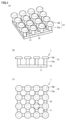
- FIG. 1 is a schematic diagram illustrating a configuration of a structure according to Embodiment 1.
- FIG. (A) is a perspective view, (b) is a side view, and (c) is a top view.
- FIG. 6 is a schematic diagram illustrating a modification of the structure according to the first embodiment.
- (A) is a top view
- (b) is a side view.
- FIG. 6 is a schematic diagram illustrating a configuration of a modified example of the structure according to the first embodiment.
- (A) is a top view
- (b) is a side view.
- FIG. 3 is a schematic cross-sectional view for explaining a configuration of a protrusion of the structure body according to the first embodiment.
- FIG. 5 is a schematic diagram illustrating a configuration of a structure according to a second embodiment.
- (A) is a perspective view
- (b) is a side view
- (c) is a top view.
- 10 is a schematic diagram illustrating a configuration of a structure according to Embodiment 3.
- FIG. (A) is a side view
- (b) is a top view. It is a schematic diagram for comparing the effect of the structure of Embodiment 3.
- (A) is a side view
- (b) is a top view.
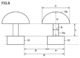
- FIG. 3 is a schematic cross-sectional view for explaining the size of each part of the protrusion according to the first embodiment. It is a cross-sectional schematic diagram for demonstrating an example of the manufacturing method of the structure of Embodiment 4.
- each embodiment is an illustration, and it cannot be overemphasized that the partial substitution or combination of the structure shown in different embodiment is possible.
- description of matters common to the first embodiment is omitted, and only different points will be described. In particular, the same operation effect by the same configuration will not be sequentially described for each embodiment.
- FIG. 1 is a schematic diagram illustrating a configuration of a structure according to the first embodiment.
- the structure 1 of the present embodiment includes a membrane-like porous body 10 having a plurality of through holes 11 and a plurality of protrusions 12.
- the plurality of protrusions 12 protrude from the portion of the membranous porous body 10 where the through holes 11 are not provided to one side in the thickness direction of the membranous porous body 10. That is, the protrusion 12 is provided on one main surface of the membranous porous body 10.
- a porous body (film-like porous body) 10 in the present embodiment has a first main surface 10a and a second main surface 10b facing the first main surface 10a.
- the through hole 11 penetrates from the first main surface 10a toward the second main surface 10b. That is, the through hole 11 penetrates in the thickness direction of the membranous porous body 10.
- the plurality of through holes 11 are periodically arranged in at least one direction on the main surface of the membranous porous body 10. Thereby, a structure with stable filtration characteristics can be obtained.
- all of the through-holes 11 may be periodically arranged, and some through-holes 11 are periodically arranged and other through-holes 11 are non-existing as long as the filtration characteristics do not become unstable. You may arrange
- the membranous porous body 10 may have an outer peripheral portion (not shown) around the plurality of through holes 11.
- an outer peripheral part turns into a part pinched by the fixing member in order to fix the structure 1 in the case of filtration, for example.
- the plurality of through-holes 11 of the membranous porous body 10 are not particularly limited as long as the target object having a predetermined size can be collected.
- the target object cannot physically pass or is difficult to pass.
- the size is preferred.
- it is preferable that it is a magnitude
- the size in which the object cannot physically pass or is difficult to pass means, for example, that the hole size of the through-hole 11 indicated by D in FIG.
- the size of the through hole 11 is equal to or less than the length of the longest straight line connecting the two upper points.
- the target object can be partially deformed for example, nucleated cells
- the size that the target object cannot physically pass or is difficult to pass means that the pore size is deformable. It means the size of the through-hole 11 that is equal to or less than the major axis of the missing part.
- the “size that the object cannot physically pass or is difficult to pass” is preferably a through-hole 11 such that the hole size is 1/20 or less of the major axis of the object. Is the size of
- the membranous porous body 10 is the membranous porous body 10 in which the through-holes 11 are regularly arranged vertically and horizontally as shown in FIG. 11, the through-hole 11 shown by D in FIG.
- the hole size is preferably, for example, not more than the length of the longest line connecting the two points on the surface of the object.
- the size of the through hole 11 is preferably 0.05 ⁇ m or more and 100 ⁇ m or less.
- the size of the through hole 11 is preferably 0.5 ⁇ m or less.
- the shape of the through hole 11 is not particularly limited.
- the shape of the through hole 11 viewed from the thickness direction of the porous body (membrane-like porous body 10) is not limited to a square as shown in FIG. 11B, but may be a rectangle, a circle, an ellipse, or the like.
- the ratio (opening ratio) of the opening area of the through hole 11 to the area of the main surface of the membranous porous body 10 including the through hole 11 is 3% or more from the viewpoint of increasing the flow rate of the fluid passing through the structure 1. Preferably, it is 10% or more. Further, from the viewpoint of ensuring the strength of the structure 1 (membrane porous body 10), it is preferably 80% or less, and more preferably 60% or less.
- the aperture ratio can be adjusted, for example, by designing the hole size of the through hole 11 indicated by D in FIG. 11B and the lattice spacing (pitch) of the through hole 11 indicated by P.
- the average thickness of the membranous porous body 10 is preferably as thin as possible within a range where necessary mechanical strength can be maintained.
- the average thickness of the membranous porous body 10 is increased, generally the pressure loss when the fluid is passed increases. This is because when the pressure loss of the structure 1 becomes large, the flow rate becomes slow and it becomes difficult to flow the fluid, so that there is a problem that the processing efficiency is lowered.
- the thickness of the structure 1 can also be reduced.
- a method for measuring an object by irradiating the structure 1 in which the object is collected with an electromagnetic wave When used for the measurement, the measurement sensitivity is improved, and it becomes possible to measure a smaller amount of the object to be measured.
- the thickness of the membranous porous body 10 is an average value (average thickness) of the distance between the first main surface 10a and the second main surface 10b.
- the average thickness of the membranous porous body 10 can be calculated as an average value of all measured values by measuring 10 locations per porous body with fluorescent X-rays.
- the average thickness of the membranous porous body 10 is preferably 0.2 ⁇ m or more and 40 ⁇ m or less, and more preferably 0.5 ⁇ m or more and 5 ⁇ m or less.
- the structure 1 of the present embodiment has a tip in which a part of the plurality of protrusions 12 overlaps the through-hole 11 in a plan view as viewed from the thickness direction of the membranous porous body 10. It has the part 12b.
- the distance between the plurality of projections 12 is narrower than the through-holes 11 of the structure 1 by the tip 12b, an object having a size that closes the through-holes 11 of the structure 1 So that it does not reach the through hole 11.
- all the side parts of the protrusion 12 are openings, even when the object is held on the upper part of the protrusion 12, a flow path can be secured on the side part. Therefore, clogging of the structure 1 due to the object can be suppressed, and a decrease in the filtration efficiency of the structure 1 can be suppressed.
- Such a clogging suppressing effect is particularly effective when the amount of the target object to be filtered is large and a large amount of the target object is deposited on the tip of the protrusion 12.
- the “plan view as viewed from the thickness direction of the membranous porous body 10” may be simply referred to as “plan view”.
- the thickness direction of the membranous porous body 10 corresponds to the normal direction of the first main surface 10a (or the second main surface 10b).
- the shape of the protrusion 12 may be such that a part of the plurality of protrusions 12 overlaps with the through hole 11 in plan view, and the base that does not overlap with the through hole 11 in plan view as shown in FIGS. 1 and 2.
- the shape is not limited to the end portion 12a and the tip portion 12b overlapping the through hole 11. That is, in the cross-sectional shape in a plane parallel to the thickness direction of the membranous porous body 10, for example, as shown in FIG.
- the shape may be a tip-expanding shape having a tapered diameter from the proximal end side toward the distal end side.
- the total number of through holes 11 of the membranous porous body 10 is 50% or more (more preferably 80% or more, more preferably substantially 100% of the through-holes 11 preferably overlap with the tip 12b of the protrusion 12. In this case, clogging can be more reliably suppressed.
- Each of the through holes 11 overlapping the tip 12b of the protrusion 12 overlaps the tip 12b of at least one protrusion 12 in a plan view as viewed from the thickness direction of the membranous porous body 10, preferably At least two protrusions 12 overlap the tip portions 12b.
- each of the through holes 11 that overlap the tip portion 12 b of the protrusion 12 overlaps the tip portions 12 b of the four protrusions 12.
- the position where the protrusion 12 is provided is not particularly limited.
- the protrusion is provided on the intersection of the crosspieces of the membranous porous body 10, but may be provided at a position other than the intersection.
- the protrusions 12 are provided on all the intersections of the crosspieces of the membranous porous body 10, but it is not necessary to provide them on all the intersections, for example, on every other intersection. You may make it provide in.
- the shape of the protrusion 12 is a shape including a base end portion 12 a that does not overlap the through hole 11 and a tip end portion 12 b that overlaps the through hole 11 in plan view. Is preferred.
- the volume of the space (gap) around the base end portion 12a is larger than the projection 12 having a shape as shown in FIG. 4, and the flow path in the vicinity of the through hole 11 is secured more widely. The effect of suppressing clogging can be enhanced.
- each of the base end portion 12a and the tip end portion 12b of the protrusion 12 is not particularly limited, and may be various shapes such as a circle and a rectangle, but is preferably a circle.
- damage due to the protrusions 12 can be suppressed.
- by chamfering the periphery of the tip damage to the object can be further suppressed.
- the hole size D of the through hole 11 of the membranous porous body 10 is, for example, 2 ⁇ m or more and 7 ⁇ m or less.
- the width A (pitch P ⁇ hole size D) of the crosspieces of the membranous porous body 10 is, for example, not less than 0.5 ⁇ m and not more than 100 ⁇ m.
- the length L of the base end portion 12a of the protrusion 12 (the length in the thickness direction of the membranous porous body 10) is, for example, not less than 0.5 ⁇ m and not more than 100 ⁇ m.
- the ratio of L to A is, for example, 10% or more and 500% or less.
- the ratio of the diameter B of the base end portion 12a of the protrusion 12 (the width in the direction perpendicular to the thickness direction in the cross section parallel to the thickness direction) to A is, for example, 10% or more and 100% or less.
- the height H of the entire protrusion 12 is, for example, 1 ⁇ m or more and 300% or less of L.
- the structure 1 (the membrane-like porous body 10 and the protrusion 12) is preferably formed at least partially including a conductor, and more preferably the entire structure 1 is formed of a conductor.
- the conductor is an object (material) that conducts electricity, and includes not only metals but also semiconductors.
- the metal examples include nickel, gold, silver, copper, platinum, iron, chromium, titanium, cobalt, and alloys thereof.
- Nickel, gold, silver, copper, platinum, chromium and titanium are preferable, and nickel and gold are more preferable.
- the structure 1 of the present embodiment can be used as a filter (sieving) for filtering an object contained in a fluid (specimen).
- a filter for filtering an object contained in a fluid (specimen).
- the membranous porous body 10 is installed in the fluid flow path so that the main surface side on which the protrusions 12 are provided is the upstream side of the fluid flow.
- the fluid is, for example, a gas or a liquid.
- the target substance include inorganic substances, organic substances or composites thereof contained in a fluid, biological substances (for example, blood cells such as erythrocytes) or microorganisms.
- the target object should just have a shape in the state which exists in the fluid, and may be not only solid but sol, gel, etc.
- Examples of the inorganic substance, the organic substance, or a composite thereof in the gas include atmospheric PM (Particulate Matter) 2.5, SPM (Suspended Particulate Matter), PM10, and pollen.
- PM2.5 is a particulate substance floating in the atmosphere, and has a particle diameter of approximately 2.5 ⁇ m or less.
- the “biological substance” has a meaning including a living substance such as a cell or a microorganism and a substance derived from a living thing such as a virus.
- Examples of cells include eukaryotic cells.
- eukaryotic cells for example, eggs, sperm, induced pluripotent stem cells (iPS cells), ES cells, stem cells, mesenchymal stem cells, mononuclear cells, single cells, cell clusters, suspension cells, adhesive cells, Examples thereof include nerve cells, leukocytes, lymphocytes, cells for regenerative medicine, autologous cells, cancer cells, circulating cancer cells (CTC), HL-60, and HeLa cells. Contains fungi.
- microorganisms include eukaryotes such as fungi, and prokaryotes such as bacteria.
- bacteria include gram positive bacteria, gram negative bacteria, Escherichia coli, and tuberculosis bacteria.
- virus examples include DNA virus, RNA virus, rotavirus, (bird) influenza virus, yellow fever virus, dengue fever virus, encephalitis virus, hemorrhagic fever virus, immunodeficiency virus, and the like.
- the structure 1 can be suitably used particularly for collecting induced pluripotent stem cells (iPS cells), ES cells, stem cells, and circulating cancer cells (CTC) in the blood.
- iPS cells induced pluripotent stem cells
- ES cells ES cells
- stem cells ES cells
- CTC cancer cells
- the structure 1 of the present embodiment can be applied to the collection of the following target object.
- exosomes endoplasmic reticulum
- the size of the exosome is about several hundred nm, and the structure 1 of the above embodiment is applied to collect (filter and concentrate) only the exosome from a blood sample from which leukocytes, erythrocytes and other blood cells have been removed. be able to.
- the structure 1 of the said embodiment can also be applied to the selective collection of such a virus.
- a protrusion 14 having a height different from that of the protrusion 12 may be provided between the plurality of protrusions 12.
- the object may be deformed toward the through-hole 11 and approach the through-hole 11 even if the object is held at the top of the protrusion 12.
- the protrusion 14 having a height different from that of the protrusion 12 the object can be prevented from approaching the through hole 11. Therefore, by providing the projection 14 having a height different from that of the projection 12, it is possible to more reliably prevent the object from blocking the through hole 11.
- the height of the protrusions 12 and 14 whole is changed by changing the height of the front-end
- the height of the protrusions 12 and 14 may be changed by changing the height of the base end portions 12a and 14a. Even in this case, the same effect as described above can be obtained.
- the structure 1 of the present embodiment is different from that of the first embodiment in that the tip of the protrusion 12 has a rounded shape. Since the other points are the same as those of the first embodiment, a duplicate description is omitted.
- the tip of the protrusion 12 has an inclined portion that is inclined with respect to a plane perpendicular to the thickness direction of the membranous porous body 10, so that the target object is softly broken like a cell. It is easy to be done, and when it is desired to filter without destroying such an object, it is possible to prevent the object from being damaged at the tip 12b of the protrusion 12. Note that, as shown in FIG. 5, not only when the entire tip of the protrusion 12 has a rounded shape, but a part of the tip of the protrusion 12 is a plane perpendicular to the thickness direction of the membranous porous body 10.
- the same effect can be obtained. Can do.
- the inclination is preferably such that the height of the tip of the protrusion 12 decreases from the center of the protrusion 12 to the outer peripheral end.
- At least one of the plurality of protrusions 12 is at least one other protrusion of the plurality of protrusions 12, and a membrane-like porous body. 10 differs from Embodiments 1 and 2 in that the length in the thickness direction is different. Since the other points are the same as those in the first and second embodiments, the overlapping description is omitted.
- the heights of some of the plurality of protrusions 13 are different from those of the other protrusions 12, the heights of the plurality of protrusions 12 are all the same as shown in FIG. 7. Even when the amount of red blood cells 9 (target object) held at the tips of the protrusions 12 and 13 is larger than in some cases, the plurality of red blood cells 9 are held in different directions, so Air gaps are easily secured and clogging is less likely to occur.
- the plurality of protrusions 12 it is not always necessary that some of the plurality of protrusions 12 overlap the through-holes 11 in a plan view as viewed from the thickness direction of the membranous porous body 10. Even in the case where a part of the plurality of protrusions 12 does not overlap with the through hole 11 in a plan view, the effect of the above-described embodiment can be obtained if the heights of the plurality of protrusions 12 are different.
- This embodiment is an embodiment of a method for manufacturing a structure.
- the structures 1 according to the first to third embodiments are, for example, known various lithography methods using a mask (resist) that is patterned so that the desired through-holes 11 and protrusions 12 are formed as described above. Etc. can be manufactured.
- the structure manufacturing method of the present embodiment mainly includes a step of forming the membranous porous body 10, a protrusion 12 formed on the membranous porous body 10, and the membranous porous body 10 and the protrusion 12 are combined. And obtaining a structure 1 comprising:
- a structure 1 comprising:
- a substrate 2 is prepared.
- substrate 2 is not specifically limited, For example, it consists of Si.
- a Ti film and a Cu film are formed in this order on the substrate 2 by sputtering to form a laminated film (metal film 3) composed of the Ti film and the Cu film.
- the metal film 3 is a layer that is removed by etching in a later step, but also functions as a seed layer for Ni plating when the film-like porous body 10 is formed.
- the thickness of the metal film 3 is not particularly limited, but is preferably as thin as possible within the range in which the structure 1 of the present embodiment can be obtained because it is partially removed in a later step. Specifically, for example, the thickness of the metal film 3 is preferably 100 to 600 nm.
- the thickness of the Ti film may be about 20 nm, and the thickness of the Cu film may be about 200 nm to 500 nm.
- a first resist 41 is formed on the metal film 3.
- the first resist 41 is patterned by a photolithography method so as to have an opening at a position corresponding to a portion where the membranous porous body 10 is formed, as shown in FIG. 9D. .
- a film-like porous body 10 (Ni film) is formed on the surface of the metal film 3 exposed in the opening of the first resist 41 by a plating method (electrolytic plating method). .
- the membranous porous body 10 having a plurality of through holes 11 penetrating in the normal direction of the main surface (the thickness direction of the membranous porous body 10) is formed.
- a second resist 42 is formed on the membranous porous body 10.
- the second resist 42 is patterned so as to have an opening at a position corresponding to a portion where the protrusion 12 is formed.
- a protrusion 12 (Ni film) is formed on the surface of the film-like porous body 10 exposed at the opening of the second resist 42 by a plating method. Accordingly, as shown in FIG. 9 (h), the protrusion 12 is formed on one main surface of the membrane-like porous body 10 (the portion where the through hole 11 is not provided) in the thickness direction of the membrane-like porous body 10. It is formed so as to include a plurality of protrusions 12 protruding in the (normal direction of the first main surface).
- the overflowed plating forms the front end portion 12 b of the protrusion 12. Note that the plating formed in the opening of the second resist 42 becomes the base end portion 12 a of the protrusion 12.
- the shape of the tip 12b of the projection 12 is usually rounded due to surface tension or the like. That is, the tip of the protrusion 12 has an inclined portion that is inclined with respect to a plane perpendicular to the thickness direction of the membranous porous body 10.
- the opening of the second resist 42 corresponding to the portion serving as the base end portion 13a of the protrusion 13 of the plurality of protrusions 12 is made more than others. Also design thinly. Thereby, since the total amount of the plurality of projections 12 and 13 formed by plating is basically the same, the tip end portion 13b of the projection 13 is larger than the tip end portion 12b of the projection 12.
- the height of the protrusion 13 can be made higher than that of the other plurality of protrusions 12 by the height of the tip end portion 13 b of the protrusion 13.
- the second resist 42 is removed by a peeling method.
- the metal film 3 is removed by etching.
- the etching method include a method of immersing the precursor of the structure 1 obtained in the above step in an etching solution for dissolving a metal film. Note that the etching solution is washed by, for example, rinsing with pure water, and then dried.
- the structure 1 of the present embodiment composed of the membranous porous body 10 and the protrusions 12 (13) can be obtained.
- the membranous porous body 10 and the protrusions 12 are formed using a resist, but the membranous porous body 10 and the protrusions 12 may be formed by other methods. For example, by using a plating bath to which a leveling agent or a brightening agent is added, the membranous porous body 10 and the protrusions 12 may be formed while simultaneously controlling the surface roughness and the shape of the protrusions. Alternatively, the membranous porous body 10 and the protrusions 12 may be formed by vapor deposition of metal, resin, or the like. Moreover, when the membranous porous body 10 and the protrusions 12 are made of resin, the membranous porous body 10 and the protrusions 12 may be formed by patterning a photocurable resin.
- the combination of the material of the membranous porous body 10 and the protrusion 12 is not particularly limited, but from the viewpoint of improving the binding properties of the both, and from the viewpoint of obtaining uniform characteristics as a whole structure when used for electromagnetic wave measurement.
- the combination of the same kind of materials is preferable.
- the present embodiment is an embodiment of a collection device using the structures of the first to third embodiments.
- the collection apparatus of this embodiment is a collection apparatus used in order to collect the target object by filtering the target object in the fluid.
- the collection measure of the present embodiment will be described with reference to FIG.
- the pretreatment filter 1 ⁇ / b> A and the structure 1 are arranged in series in the flow path formed by the cylinder 5. That is, the pretreatment filter 1A is provided on the upstream side of the structure 1 in the fluid flow path.
- the pretreatment filter 1A is a filter through which a foreign substance larger than the target object cannot pass and a target object, a foreign substance smaller than the target object, and a fluid can pass.
- the structure 1 for example, the structure of any of the first to third embodiments is used. Thereby, the collection apparatus which can suppress clogging and can suppress the fall of filtration efficiency can be provided.
- pretreatment filter 1A for example, a membrane filter or the structures of the first to third embodiments can be used. Further, a plurality of these preprocessing filters may be arranged in series.
- the size of the through hole 11 (for example, the hole size of the through hole 11 indicated by D in FIG. 11B) is larger than the target product. It is preferable that the foreign substance cannot pass through or is difficult to pass through, and the target article can pass through. Thereby, in the pre-processing filter 1A, the target object can be passed without being removed, and only impurities larger than the target object can be collected (removed). Therefore, clogging of the structure 1 due to contaminants can be suppressed, and a decrease in filtration efficiency can be further suppressed.
- the membranous porous body 10 is a membranous porous body in which the through-holes 11 are regularly arranged in the vertical and horizontal directions as shown in FIG. 11A
- the size of the hole 11 is larger than the size of the target object (for example, the length of the longest straight line connecting two points on the surface of the target object), and is larger than the target object (for example, the foreign object). It is preferable that the length of the longest straight line connecting two points on the surface is less than or equal to.
- Embodiments 1 to 3 that can suppress clogging as the pretreatment filter 1A, clogging due to contaminants in the pretreatment filter 1A can be suppressed. Further, by using the structure according to the first to third embodiments having a larger flow rate ratio than the membrane filter or the like as the pretreatment filter 1A, the pressure loss of the entire collection device can be reduced and the filtration efficiency can be improved. .
- Example 1 A membranous porous body 10 having a diameter of 6 mm was produced at the center of a structure made of a circular nickel film having a diameter of 7.8 mm.
- the hole size D of the through hole 11 of the membranous porous body 10 is 4.5 ⁇ m
- the width A of the crosspiece is 2.0 ⁇ m
- the length L of the base end portion 12 a is The diameter B of the base end portion 12a was 1 ⁇ m
- the height H of the entire protrusion 12 was 5.5 ⁇ m.
- the film thickness of the membranous porous body 10 was 1.5 ⁇ m.
- Example 1 Although it was the same as in Example 1, a membranous porous body without protrusions was prepared, and the cell suspension similar to that in Example 1 was filtered by the dead end method. As a result, even after 10 minutes, the cells and the liquid could not be separated completely. At the time when 6 minutes had passed, the through-holes of the membranous porous body were blocked by cells, so that the liquid did not pass through the membranous porous body.
Landscapes
- Chemical & Material Sciences (AREA)
- Chemical Kinetics & Catalysis (AREA)
- Apparatus Associated With Microorganisms And Enzymes (AREA)
- Separation Using Semi-Permeable Membranes (AREA)
Abstract
複数の貫通孔を有する多孔体と、前記多孔体の前記貫通孔が設けられていない部分から前記多孔体の厚み方向の少なくとも一方に突出する複数の突起とを備えており、前記突起は、前記多孔体の厚み方向から見た平面視において、前記貫通孔と重なっている先端部を有する、構造体。
Description
本発明は、構造体および捕集装置に関する。
流体(検体)中の固体等を濾過するために用いられる複数の貫通孔を有する多孔体が知られている。
特許文献1(特開2012-196617号公報)には、複数の貫通孔を有する基板(多孔体)を用いて、貫通孔より大きな粒子を濾過し、貫通孔より小さな粒子を通過させて粒子を分級するための篩が開示されている。そして、特許文献1には、貫通孔より小さな粒子が互いにくっ付きあって塊となり、貫通孔を通過できなくなるという問題を解消するために、多孔体の入口側に粒子同士を分離するための複数の円錐状または円柱状の突起を設けることが開示されている。
特許文献1に開示される多孔体では、多孔体の入口側に突起を設けることで、塊となった粒子が分離するとともに、粒子が多孔体上へ固着することが妨げられるため、突起が存在しない多孔体に比べて粒子がより貫通孔へ導かれ易くなる。これにより、貫通孔の径よりも小さい物体は貫通孔を通過し易くなると考えられる。
しかしながら、貫通孔と同等もしくは貫通孔よりやや大きい物体も、貫通孔へ導かれ易くなるため、そのような物体による貫通孔の閉塞が助長されると考えられる。特に、そのような貫通孔と同等もしくは貫通孔よりやや大きい物体の量が多くなると、多孔体が目詰まりを起こすリスクが高まる。そして、目詰まりが発生すると、多孔体の濾過効率が急激に低下してしまうという問題があった。
本発明は、上記の事情に鑑み、目詰まりを抑制し、濾過効率の低下を抑制することのできる構造体および捕集装置を提供することを目的とする。
[1] 複数の貫通孔を有する多孔体と、
前記多孔体の前記貫通孔が設けられていない部分から前記多孔体の厚み方向の少なくとも一方に突出する複数の突起とを備えており、
前記突起は、前記多孔体の厚み方向から見た平面視において、前記貫通孔と重なっている先端部を有する、構造体。
前記多孔体の前記貫通孔が設けられていない部分から前記多孔体の厚み方向の少なくとも一方に突出する複数の突起とを備えており、
前記突起は、前記多孔体の厚み方向から見た平面視において、前記貫通孔と重なっている先端部を有する、構造体。
[2] 前記複数の突起は、前記多孔体の厚み方向から見た平面視において、前記貫通孔と重ならない基端部を有する、[1]に記載の構造体。
[3] 前記先端部は、前記多孔体の厚み方向に垂直な平面に対して傾斜した傾斜部を有する、[1]または[2]に記載の構造体。
[4] 複数の貫通孔を有する多孔体と、
前記多孔体の前記貫通孔が設けられていない部分から前記多孔体の厚み方向の少なくとも一方に突出する複数の突起とを備えており、
前記複数の突起のうちの少なくとも1つは、前記複数の突起のうちの他の少なくとも1つの突起と、前記多孔体の厚み方向の長さが異なる、構造体。
前記多孔体の前記貫通孔が設けられていない部分から前記多孔体の厚み方向の少なくとも一方に突出する複数の突起とを備えており、
前記複数の突起のうちの少なくとも1つは、前記複数の突起のうちの他の少なくとも1つの突起と、前記多孔体の厚み方向の長さが異なる、構造体。
[5] 前記突起は、前記多孔体の厚み方向から見た平面視において、前記貫通孔と重なっている先端部を有する、[4]に記載の構造体。
[6] 前記先端部は、前記多孔体の厚み方向に垂直な平面に対して傾斜した傾斜部を有する、[1]~[5]のいずれかに記載の構造体。
[7] 流体中の目的物を捕集するために用いられる捕集装置であって、
[1]~[6]のいずれかに記載の構造体と、
前記流体の流路において前記構造体の上流側に設けられ、前記目的物よりも大きな夾雑物が通過できず、前記目的物、前記目的物より小さな夾雑物、および、前記流体が通過可能な前処理フィルタと、を備える捕集装置。
[1]~[6]のいずれかに記載の構造体と、
前記流体の流路において前記構造体の上流側に設けられ、前記目的物よりも大きな夾雑物が通過できず、前記目的物、前記目的物より小さな夾雑物、および、前記流体が通過可能な前処理フィルタと、を備える捕集装置。
本発明によれば、目詰まりを抑制し、濾過効率の低下を抑制することのできる構造体および捕集装置を提供することができる。
以下、本発明の実施形態について、図面を参照して説明する。なお、図面において、同一の参照符号は、同一部分または相当部分を表す。また、長さ、幅、厚さ、深さなどの寸法関係は図面の明瞭化と簡略化のために適宜変更されており、実際の寸法関係を表すものではない。
なお、各実施形態は例示であり、異なる実施形態で示した構成の部分的な置換または組み合わせが可能であることは言うまでもない。実施形態2以降では実施形態1と共通の事柄についての記述を省略し、異なる点についてのみ説明する。特に、同様の構成による同様の作用効果については実施形態毎には逐次言及しない。
[実施形態1]
図1は、実施形態1の構造体の構成を示す概略図である。図1を参照して、本実施形態の構造体1は、複数の貫通孔11を有する膜状多孔体10と、複数の突起12とを備えている。
図1は、実施形態1の構造体の構成を示す概略図である。図1を参照して、本実施形態の構造体1は、複数の貫通孔11を有する膜状多孔体10と、複数の突起12とを備えている。
複数の突起12は、膜状多孔体10の貫通孔11が設けられていない部分から膜状多孔体10の厚み方向の一方に突出している。すなわち、突起12は膜状多孔体10の一方の主面に設けられている。
(多孔体)
図11を参照して、本実施形態における多孔体(膜状多孔体)10は、第1主面10aと、第1主面10aと対向する第2主面10bとを有している。貫通孔11は第1主面10aから第2主面10bに向かって貫通している。すなわち、貫通孔11は、膜状多孔体10の厚み方向に貫通している。
図11を参照して、本実施形態における多孔体(膜状多孔体)10は、第1主面10aと、第1主面10aと対向する第2主面10bとを有している。貫通孔11は第1主面10aから第2主面10bに向かって貫通している。すなわち、貫通孔11は、膜状多孔体10の厚み方向に貫通している。
本実施形態の膜状多孔体においては、複数の貫通孔11が膜状多孔体10の主面上の少なくとも一方向に周期的に配置されていることが好ましい。これにより、濾過特性が安定した構造体を得ることができる。ただし、貫通孔11は、その全てが周期的に配置されていてもよく、濾過特性が不安定にならない範囲で、一部の貫通孔11が周期的に配置され、他の貫通孔11が非周期的に配置されていてもよい。
なお、膜状多孔体10は、複数の貫通孔11の周囲に外周部(図示せず)を有していてもよい。なお、外周部は、例えば、濾過の際に構造体1を固定するために固定部材によって挟持される部分となる。
膜状多孔体10の複数の貫通孔11は、所定の大きさの目的物を捕集できる大きさであれば特に限定されないが、例えば、物理的に目的物が通過できないか、または通過し難い大きさであることが好ましい。また、流体が容易に通過できる大きさであることが好ましい。
「物理的に目的物が通過できないか、または通過し難い大きさ」とは、例えば、図11(b)にDで示される貫通孔11の孔サイズが、目的物の長径(目的物の表面上の2点間を結ぶ直線のうち最長のものの長さ)以下となるような、貫通孔11の大きさである。なお、目的物が部分的に変形しうるものである場合(例えば、有核細胞)、「物理的に目的物が通過できないか、または通過し難い大きさ」とは、孔サイズが変形能が無い部分の長径以下となるような貫通孔11の大きさを意味する。目的物の全体が変形する場合、「物理的に目的物が通過できないか、または通過し難い大きさ」は、好ましくは孔サイズが目的物の長径の1/20以下となるような貫通孔11の大きさである。
例えば、膜状多孔体10が、貫通孔11が図11に示すように縦横に規則的に配置された膜状多孔体10である場合において、図11(b)にDで示される貫通孔11の孔サイズは、例えば、目的物の表面上の2点間を結ぶ直線のうち最長のものの長さ以下であることが好ましい。
具体的には、貫通孔11のサイズは、0.05μm以上100μm以下であることが好ましい。なお、例えば、サブミクロンオーダーの粒子を構造体1で捕集したい場合、貫通孔11のサイズは、0.5μm以下であることが好ましい。
貫通孔11の形状は、特に限定されない。多孔体(膜状多孔体10)の厚み方向から見た貫通孔11の形状は、図11(b)に示されるような正方形だけでなく、長方形、円形、楕円形などであってもよい。
貫通孔11を含む膜状多孔体10の主面の面積に対する貫通孔11の開口面積の比率(開口率)は、構造体1を通過する流体の流速を高める観点から3%以上であることが好ましく、10%以上であることがより好ましい。また、構造体1(膜状多孔体10)の強度保証の観点から、80%以下であることが好ましく、60%以下であることがより好ましい。なお、開口率は、例えば、図11(b)にDで示される貫通孔11の孔サイズとPで示される貫通孔11の格子間隔(ピッチ)の設計によって調整することができる。
膜状多孔体10の平均厚みは、必要な機械的強度を維持できる範囲で、薄い方が好ましい。膜状多孔体10の平均厚みが厚くなると、一般に流体を通過させた際の圧力損失が大きくなる。構造体1の圧力損失が大きくなると、流速が遅くなったり、流体を流すことが困難になったりするため、処理効率が低下するといった問題があるからである。
また、膜状多孔体10の平均厚みを薄くすることで、構造体1の厚みも薄くすることができ、例えば、目的物が捕集された構造体1に電磁波を照射する目的物の測定方法に用いた場合、測定感度が向上し、より微量の被測定物を測定することが可能となる。ここで、膜状多孔体10の厚みとは、第1主面10aと第2主面間10bとの間の距離の平均値(平均厚み)である。膜状多孔体10の平均厚みは、蛍光X線にて多孔体1枚につき10か所を測定し、全測定値の平均値として算出することができる。
具体的に、膜状多孔体10の平均厚みは、好ましくは0.2μm以上40μm以下であり、より好ましくは0.5μm以上5μm以下である。
(突起)
本実施形態の構造体1は、図1(c)に示すように、膜状多孔体10の厚み方向から見た平面視において、複数の突起12の一部が貫通孔11と重なっている先端部12bを有していることを特徴としている。
本実施形態の構造体1は、図1(c)に示すように、膜状多孔体10の厚み方向から見た平面視において、複数の突起12の一部が貫通孔11と重なっている先端部12bを有していることを特徴としている。
この先端部12bによって、構造体1の貫通孔11より複数の突起12の間隔の方が狭くなるため、構造体1の貫通孔11を閉塞してしまう大きさの目的物を、突起12の部分で保持し、貫通孔11に到達しないようにすることができる。なお、突起12は側部が全て開口部となっているため、突起12の上部に目的物が保持された場合でもその側部で流路を確保できる。したがって、目的物による構造体1の目詰まりを抑制し、構造体1の濾過効率の低下を抑制することができる。このような目詰まりの抑制効果は、濾過する目的物の量が多く、突起12の先端上に多量の目的物が堆積した場合において、特に有効である。
なお、本明細書においては、「膜状多孔体10の厚み方向から見た平面視」を、単に「平面視」という場合がある。また、本実施形態において、膜状多孔体10の厚み方向は、第1主面10a(または第2主面10b)の法線方向に相当する。
突起12の形状は、平面視において、複数の突起12の一部が貫通孔11と重なっていればよく、図1および図2に示されるような、平面視において、貫通孔11と重ならない基端部12aと、貫通孔11と重なる先端部12bとからなる形状に限られない。すなわち、膜状多孔体10の厚み方向に平行な平面における断面形状において、例えば、図4に示されるように、膜状多孔体10の桟部(貫通孔11が設けられていない部分)に接する基端側から先端側に向けてテーパー状に径が長くなっている先広がりの形状であってもよい。
なお、膜状多孔体10の厚み方向から見た平面視において、膜状多孔体10の複数の貫通孔11のうち、全体の数の50%以上(より好ましくは80%以上、さらに好ましくは実質的100%)の貫通孔11が突起12の先端部12bと重なっていることが好ましい。この場合、より確実に目詰まりを抑制することができる。
また、膜状多孔体10の厚み方向から見た平面視において、突起12の先端部12bと重なっている貫通孔11の各々は、少なくとも1つの突起12の先端部12bと重なっており、好ましくは少なくとも2つの突起12の先端部12bと重なっている。なお、図1(c)および図2(a)においては、突起12の先端部12bと重なっている貫通孔11の各々は、4つの突起12の先端部12bと重なっている。
また、突起12を設ける位置も特に限定されない。図1および図2では、突起は、膜状多孔体10の桟部の交点上に設けられているが、交点以外の位置に設けてもよい。また、図1および図2では、膜状多孔体10の桟部の全ての交点上に突起12が設けられているが、全ての交点上に設ける必要はなく、例えば、1つ置きの交点上に設けるようにしてもよい。
ただし、突起12の形状は、図1および図2に示されるように、平面視において、貫通孔11と重ならない基端部12aと、貫通孔11と重なる先端部12bとからなる形状であることが好ましい。この場合、図4に示すような形状の突起12に比べて、基端部12aの周囲の空間(空隙)の体積が大きくなり、貫通孔11の近傍の流路がより広く確保されるため、目詰まりの抑制効果を高めることができる。
なお、突起12の基端部12aおよび先端部12bの各々の平面視における形状は、特に限定されず、円、方形などの種々の形状であってよいが、好ましくは円形である。目的物が赤血球等のダメージを受けやすいものである場合に、突起12によるダメージを抑制することができる。また、先端部の周囲を面取りすることにより、目的物へのダメージをより一層抑制することができる。
図8および図1(b)を参照して、膜状多孔体10および突起12の各部の具体的なサイズについて例示すれば、以下のとおりである。
例えば、目的物のサイズが8μm以上14μm以下である場合、膜状多孔体10の貫通孔11の孔サイズDは、例えば、2μm以上7μm以下である。また、膜状多孔体10の桟部の幅A(ピッチP-孔サイズD)は、例えば、0.5μm以上100μm以下である。
突起12の基端部12aの長さL(膜状多孔体10の厚み方向の長さ)は、例えば、0.5μm以上100μm以下である。なお、LのAに対する比率は、例えば、10%以上500%以下である。
突起12の基端部12aの径B(厚み方向に平行な断面における厚み方向に垂直な方向の幅)のAに対する比率は、例えば、10%以上100%以下である。また、突起12全体の高さH(膜状多孔体10の厚み方向の長さ)は、例えば、1μm以上であり、Lの300%以下である。
構造体1(膜状多孔体10および突起12)は、少なくともその表面を含む一部が導体で形成されていることが好ましく、構造体1の全体が導体で形成されていることがより好ましい。ここで、導体とは、電気を通す物体(物質)のことであり、金属だけでなく半導体も含まれる。
金属としては、ニッケル、金、銀、銅、白金、鉄、クロム、チタン、コバルト、および、これらの合金などが挙げられる。好ましくはニッケル、金、銀、銅、白金、クロムおよびチタンであり、さらに好ましくはニッケルおよび金である。
本実施形態の構造体1は、流体(検体)中に含まれる目的物を濾過するためのフィルタ(篩い)として用いることができる。なお、濾過を行う際、膜状多孔体10は、突起12が設けられた主面側が流体の流れの上流側となるように流体の流路に設置されることが好ましい。
流体は、例えば、気体または液体である。目的物としては、例えば、流体中に含まれる無機物、有機物もしくはそれらの複合物、または、生物由来物質(例えば、赤血球などの血液細胞)もしくは微生物が挙げられる。なお、目的物は、流体中に存在する状態で形状を有しているものであればよく、固体に限らず、ゾル、ゲル等であってもよい。
気体中の無機物、有機物もしくはそれらの複合物としては、例えば、大気中のPM(Particulate Matter)2.5や、SPM(Suspended Particulate Matter)、PM10、花粉などが挙げられる。なお、PM2.5とは、大気中に浮遊する粒子状物質であり、粒子径が概ね2.5μm以下のものである。
「生物由来物質」とは、細胞、微生物などの生物自体と、ウィルス等の生物に由来する物質と、を包含する意味を有している。
細胞としては、真核細胞が挙げられる。真核細胞としては、例えば、卵、精子、人工多能性幹細胞(iPS細胞)、ES細胞、幹細胞、間葉系幹細胞、単核球細胞、単細胞、細胞塊、浮遊性細胞、接着性細胞、神経細胞、白血球、リンパ球、再生医療用細胞、自己細胞、がん細胞、血中循環がん細胞(CTC)、HL-60、HeLa細胞などが挙げれらる。菌類を含む。
微生物としては、菌類等の真核生物、細菌等の原核生物が挙げられる。細菌(真正細菌)としては、例えば、グラム陽性菌、グラム陰性菌、大腸菌、結核菌などが挙げられる。
ウィルスとしては、例えば、DNAウィルス、RNAウィルス、ロタウィルス、(鳥)インフルエンザウィルス、黄熱病ウィルス、デング熱病ウィルス、脳炎ウィルス、出血熱ウィルス、免疫不全ウィルスなどが挙げられる。
実施形態1においては、構造体1は、特に、人工多能性幹細胞(iPS細胞)、ES細胞、幹細胞、血中循環がん細胞(CTC)の捕集に好適に用いることができる。
上述の目的物以外にも、例えば以下のような目的物の捕集に、本実施形態の構造体1を適用することができる。
癌の新しい検査方法として、血中の癌細胞由来のエクソソーム(小胞体)を定量する研究が進められている。エクソソームのサイズは数百nm程度であり、白血球、赤血球および他の血液細胞を除去した血液サンプルから、エクソソームのみを捕集(濾過および濃縮)するために、上記実施形態の構造体1を適用することができる。
また、ノロウィルスは培養できないため、発病後、かなりの時間が経過して、ウィルス数が増えないと検査できないという問題があるが、微量なウィルスを構造体1で捕集(濾過および濃縮)できれば、培養不要で迅速な検査が可能になる。このため、上記実施形態の構造体1は、このようなウィルスの選択的な捕集に適用することもできる。
なお、図3に示されるように、複数の突起12の間に、さらに突起12とは高さが異なる突起14を設けてもよい。例えば、細胞の様な変形しうる目的物を濾過する場合、突起12の上部で保持したとしても、目的物が貫通孔11に向かって変形し、貫通孔11に接近することがある。このとき、突起12とは高さが異なる突起14を配置することで、目的物が貫通孔11に接近することを抑制できる。したがって、このような突起12と高さが異なる突起14を設けることで、より確実に、目的物が貫通孔11を塞ぐことを抑制することができる。
なお、図3(b)では、突起12,14の先端部12b,14bの高さを変えることで、突起12,14全体の高さを変えている。ただし、基端部12a,14aの高さを変えることで、突起12,14の高さを変えてもよい。この場合でも、上記と同様の効果を得ることができる。
[実施形態2]
図5を参照して、本実施形態の構造体1は、突起12の先端部が丸みを帯びた形状である点で実施形態1と異なる。それ以外の点は、実施形態1と同様であるため、重複する説明は省略する。
図5を参照して、本実施形態の構造体1は、突起12の先端部が丸みを帯びた形状である点で実施形態1と異なる。それ以外の点は、実施形態1と同様であるため、重複する説明は省略する。
本実施形態のように、突起12の先端部が、膜状多孔体10の厚み方向に垂直な平面に対して傾斜した傾斜部を有していることで、目的物が細胞のような柔らかく破壊され易いものであり、このような目的物を破壊せずに濾過したい場合に、このような目的物が突起12の先端部12bでダメージを受けてしまうことを抑制できる。なお、図5に示されるように突起12の先端部の全体が丸みを帯びた形状である場合に限らず、突起12の先端部の一部が膜状多孔体10の厚み方向に垂直な平面に対して傾斜した傾斜部を有していれば(例えば、先端部が基本的には矩形状であるが、角部が面取りされているような形状であれば)、同様の効果を得ることができる。上記の傾斜は、突起12の中央から外周端部にかけて突起12の先端の高さが低くなるような傾斜であることが好ましい。
[実施形態3]
図6を参照して、本実施形態の構造体は、複数の突起12のうちの少なくとも1つ(突起13)は、複数の突起12のうちの他の少なくとも1つの突起と、膜状多孔体10の厚み方向の長さが異なる点で、実施形態1および2とは異なる。それ以外の点は、実施形態1および2と同様であるため、重複する説明は省略する。
図6を参照して、本実施形態の構造体は、複数の突起12のうちの少なくとも1つ(突起13)は、複数の突起12のうちの他の少なくとも1つの突起と、膜状多孔体10の厚み方向の長さが異なる点で、実施形態1および2とは異なる。それ以外の点は、実施形態1および2と同様であるため、重複する説明は省略する。
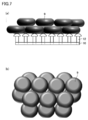
図6に示されるように、複数の突起のうち一部の突起13の高さが他の突起12と異なっている場合、図7に示されるように複数の突起12の高さが全て同じである場合に比べて、突起12,13の先端に保持された赤血球9(目的物)の量が多くなった場合でも、複数の赤血球9が異なる向きで保持されることで、赤血球9の間に空隙が確保されやすく、目詰まりを生じにくくなる。
なお、ここでは、一部の突起13が他の複数の突起12より高さが高い場合について説明したが、逆に一部の突起が他の複数の突起より高さが低い場合であっても、同様の効果が奏される。
また、本実施形態においては、必ずしも、膜状多孔体10の厚み方向から見た平面視において、複数の突起12の一部が貫通孔11と重なっている必要はない。平面視において複数の突起12の一部が貫通孔11と重なっていない場合であっても、複数の突起12の高さが異なっていれば、上述の本実施形態の効果は奏される。
[実施形態4]
本実施形態は、構造体の製造方法の一実施形態である。上記実施形態1~3の構造体1は、例えば、上記のような所望の貫通孔11や突起12が形成されるようにパターン設計されたマスク(レジスト)を用いて、公知の種々のリソグラフィー法などによって製造することができる。
本実施形態は、構造体の製造方法の一実施形態である。上記実施形態1~3の構造体1は、例えば、上記のような所望の貫通孔11や突起12が形成されるようにパターン設計されたマスク(レジスト)を用いて、公知の種々のリソグラフィー法などによって製造することができる。
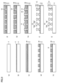
本実施形態の構造体の製造方法は、主に、膜状多孔体10を形成する工程と、膜状多孔体10上に突起12を形成し、膜状多孔体10と突起12とが結合されてなる構造体1を得る工程とを含む。以下、図9を参照して、本実施形態の構造体の製造方法の一例について説明する。
まず、図9(a)を参照して、基板2を用意する。基板2は、特に限定されないが、例えば、Siからなる。
次に、図9(b)を参照して、基板2上に、スパッタリングによりTi膜及びCu膜をこの順序で製膜し、Ti膜及びCu膜からなる積層膜(金属膜3)を形成する。この金属膜3は、後の工程でエッチングによって除去される層であるが、膜状多孔体10を形成する際に、Niのめっきに際してのシード層としても機能する。また、その他の効果として、例えばCu膜の表面粗さを調整し、調整後の表面状態をNi面に転写できる効果もある。
金属膜3の厚みは、特に限定されないが、後の工程で部分的に除去されるものであるため、本実施形態の構造体1を得られる範囲内で薄い方が好ましい。具体的には、例えば、金属膜3の厚みは、100~600nmであることが好ましい。なお、例えば、Ti膜の厚みは20nm程度とすればよく、Cu膜の厚みは200nm~500nm程度とすればよい。
次に、図9(c)を参照して、金属膜3上に第1レジスト41を形成する。次に、この第1レジスト41は、フォトリソグラフィー法により、図9(d)に示されるように、膜状多孔体10が形成される部分に相当する位置に、開口を有するようにパターニングされる。
次に、図9(e)を参照して、第1レジスト41の開口において露出した金属膜3の表面上に、膜状多孔体10(Ni膜)をめっき法(電解めっき法)により形成する。このようにして、主面の法線方向(膜状多孔体10の厚み方向)に貫通する複数の貫通孔11を有する膜状多孔体10が形成される。
次に、図9(f)を参照して、膜状多孔体10上に、第2レジスト42を形成する。次に、第2レジスト42は、図9(g)に示されるように、突起12が形成される部分に相当する位置に、開口を有するようにパターニングされる。
次に、図9(h)を参照して、第2レジスト42の開口において露出した膜状多孔体10の表面上に、突起12(Ni膜)をめっき法により形成する。これにより、図9(h)に示されるように、突起12は、膜状多孔体10の一方の主面上(貫通孔11が設けられていない部分)に、膜状多孔体10の厚み方向(第1主面の法線方向)に突出した複数の突起12を含むように形成される。
このとき、めっき量(めっき時間)を第2レジスト42の開口から溢れるように調整することで、溢れて形成されためっきが突起12の先端部12bを形成する。なお、第2レジスト42の開口内に形成されためっきが突起12の基端部12aとなる。
この場合、突起12の先端部12bの形状は、通常、表面張力等によって丸みを帯びた形状となる。すなわち、突起12の先端部が、膜状多孔体10の厚み方向に垂直な平面に対して傾斜した傾斜部を有することとなる。
なお、実施形態3の構造体1を得る場合は、例えば、複数の突起12のうちの一部の突起13について、その基端部13aとなる部分に対応する第2レジスト42の開口を他よりも細く設計しておく。これにより、めっきによって形成される複数の突起12,13の全量は基本的に同じであるため、突起13の先端部13bは、突起12の先端部12bよりも大きくなる。この突起13の先端部13bの高さによって、突起13の高さを他の複数の突起12よりも高くすることができる。
次に、図9(i)を参照して、第2レジスト42を剥離法により除去する。
次に、図9(j)を参照して、金属膜3をエッチングにより除去する。エッチング方法としては、例えば、金属膜を溶解するエッチング液に上記の工程で得られた構造体1の前駆体を浸漬する方法が挙げられる。なお、エッチング液は、例えば、純水を用いたリンスによって洗浄し、その後に乾燥が行われる。
次に、図9(j)を参照して、金属膜3をエッチングにより除去する。エッチング方法としては、例えば、金属膜を溶解するエッチング液に上記の工程で得られた構造体1の前駆体を浸漬する方法が挙げられる。なお、エッチング液は、例えば、純水を用いたリンスによって洗浄し、その後に乾燥が行われる。
上記の工程によって、膜状多孔体10および突起12(13)から構成される本実施形態の構造体1を得ることができる。
なお、本実施形態では、レジストを用いて膜状多孔体10および突起12を形成したが、他の方法で膜状多孔体10および突起12を形成してもよい。例えば、レベリング剤や光沢剤が添加されためっき浴を用いることで、表面粗さや突起の形状も同時に制御しながら膜状多孔体10および突起12を形成してもよい。また、金属、樹脂等を蒸着することにより、膜状多孔体10および突起12を形成してもよい。また、膜状多孔体10および突起12が樹脂からなる場合、光硬化性樹脂をパターニングすることにより、膜状多孔体10および突起12を形成してもよい。
なお、膜状多孔体10と突起12との材料の組み合わせは、特に限定されないが、両者の結合性を高める観点や、電磁波測定に用いられる場合に構造体全体として均一な特性を得る観点からは、同種の材料の組み合わせであることが好ましい。
[実施形態5]
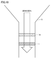
本実施形態は、上記実施形態1~3の構造体を用いた捕集装置の実施形態である。なお、本実施形態の捕集装置は、流体中の目的物を濾過することにより、目的物を捕集するために用いられる捕集装置である。以下、図10を参照して、本実施形態の捕集措置について説明する。
本実施形態は、上記実施形態1~3の構造体を用いた捕集装置の実施形態である。なお、本実施形態の捕集装置は、流体中の目的物を濾過することにより、目的物を捕集するために用いられる捕集装置である。以下、図10を参照して、本実施形態の捕集措置について説明する。
図10に示されるように、前処理フィルタ1Aと、構造体1とが筒体5によって形成される流路内に直列に配置されている。すなわち、前処理フィルタ1Aは、流体の流路において構造体1の上流側に設けられている。
そして、前処理フィルタ1Aは、目的物よりも大きな夾雑物が通過できず、目的物、目的物より小さな夾雑物、および、流体が通過可能なフィルタである。
本実施形態の捕集装置において、構造体1としては、例えば、上記実施形態1~3のいずれかの構造体を用いる。これにより、目詰まりを抑制し、濾過効率の低下を抑制することのできる捕集装置を提供することができる。
前処理フィルタ1Aとしては、例えば、メンブレンフィルタや上記実施形態1~3の構造体を用いることができる。また、それらの前処理フィルタを複数直列に並べて使用してもよい。
前処理フィルタ1Aとして、上記実施形態1~3の構造体を用いる場合、貫通孔11のサイズ(例えば、図11(b)にDで示される貫通孔11の孔サイズ)は、目的物より大きな夾雑物が通過できないか、または通過し難い大きさであり、かつ、目的物が通過できる大きさであることが好ましい。これにより、前処理フィルタ1Aでは、目的物を除去することなく通過させ、目的物より大きな夾雑物のみを捕集(除去)することができる。したがって、夾雑物による構造体1の目詰まりを抑制し、濾過効率の低下をさらに抑制することができる。
例えば、膜状多孔体10が、貫通孔11が図11(a)に示すように縦横に規則的に配置された膜状多孔体である場合において、図11(b)にDで示される貫通孔11の孔サイズは、目的物のサイズ(例えば、目的物の表面上の2点間を結ぶ直線のうち最長のものの長さ)より大きく、目的物より大きな夾雑物のサイズ(例えば、夾雑物の表面上の2点間を結ぶ直線のうち最長のものの長さ)以下であることが好ましい。
そして、このような前処理フィルタ1Aおよび構造体1をこの順で通過するように、流体(検体)を流すことにより、前処理フィルタ1Aで目的物より大きい夾雑物を除去し、構造体1で目的物を捕集することができる。
前処理フィルタ1Aとして、目詰まりを抑制することのできる上記実施形態1~3の構造体を用いることで、前処理フィルタ1Aの夾雑物による目詰まりも抑制することができる。また、前処理フィルタ1Aとして、メンブレンフィルタ等よりも流速比率が大きい上記実施形態1~3の構造体を用いることで、捕集装置全体の圧力損失を低減し、濾過効率を向上させることができる。
(実施例1)
直径7.8mmの円形ニッケル膜からなる構造体の中心部に、直径6mmの膜状多孔体10を作製した。膜状多孔体10は、図8を参照し、膜状多孔体10の貫通孔11の孔サイズDは4.5μm、桟部の幅Aは2.0μm、基端部12aの長さLは4μm、基端部12aの径Bは1μm、突起12全体の高さHは5.5μmであった。また、膜状多孔体10の膜厚は1.5μmであった。
直径7.8mmの円形ニッケル膜からなる構造体の中心部に、直径6mmの膜状多孔体10を作製した。膜状多孔体10は、図8を参照し、膜状多孔体10の貫通孔11の孔サイズDは4.5μm、桟部の幅Aは2.0μm、基端部12aの長さLは4μm、基端部12aの径Bは1μm、突起12全体の高さHは5.5μmであった。また、膜状多孔体10の膜厚は1.5μmであった。
この構造体に、概ね球形で大きさが12μmの細胞HL60が1×10⁴個含まれた懸濁液を投入した。液量は10mLであった。デッドエンド方式による濾過の結果、265秒で細胞と液体を全量分離することができた。
(比較例1)
実施例1と同様ではあるが、突起を備えない膜状多孔体を作製し、実施例1と同様の細胞の懸濁液をデッドエンド方式で濾過した。その結果、10分が経過しても、細胞と液体を全量分離することができなかった。6分が経過した時点で、膜状多孔体の貫通孔が細胞によって閉塞されたために、液体が膜状多孔体を通過しなくなった。
実施例1と同様ではあるが、突起を備えない膜状多孔体を作製し、実施例1と同様の細胞の懸濁液をデッドエンド方式で濾過した。その結果、10分が経過しても、細胞と液体を全量分離することができなかった。6分が経過した時点で、膜状多孔体の貫通孔が細胞によって閉塞されたために、液体が膜状多孔体を通過しなくなった。
(結果1)
本発明に係る実施例1では、比較例1と比べて、目詰まりを抑制し、濾過効率を向上させることができた。
本発明に係る実施例1では、比較例1と比べて、目詰まりを抑制し、濾過効率を向上させることができた。
今回開示された実施形態はすべての点で例示であって制限的なものではないと考えられるべきである。本発明の範囲は上記した説明ではなくて請求の範囲によって示され、請求の範囲と均等の意味および範囲内でのすべての変更が含まれることが意図される。
1 構造体、1A 前処理フィルタ、10 膜状多孔体、10a 第1主面,10b 第2主面、11 貫通孔、12,13,14 突起、12a,13a,14a 基端部、12b,13b,14b 先端部、2 基板、3 金属膜、41 第1レジスト、42 第2レジスト、5 筒体、9 赤血球。
Claims (7)
- 複数の貫通孔を有する多孔体と、
前記多孔体の前記貫通孔が設けられていない部分から前記多孔体の厚み方向の少なくとも一方に突出する複数の突起とを備えており、
前記突起は、前記多孔体の厚み方向から見た平面視において、前記貫通孔と重なっている先端部を有する、構造体。 - 前記複数の突起は、前記多孔体の厚み方向から見た平面視において、前記貫通孔と重ならない基端部を有する、請求項1に記載の構造体。
- 前記先端部は、前記多孔体の厚み方向に垂直な平面に対して傾斜した傾斜部を有する、請求項1または2に記載の構造体。
- 複数の貫通孔を有する多孔体と、
前記多孔体の前記貫通孔が設けられていない部分から前記多孔体の厚み方向の少なくとも一方に突出する複数の突起とを備えており、
前記複数の突起のうちの少なくとも1つは、前記複数の突起のうちの他の少なくとも1つの突起と、前記多孔体の厚み方向の長さが異なる、構造体。 - 前記突起は、前記多孔体の厚み方向から見た平面視において、前記貫通孔と重なっている先端部を有する、請求項4に記載の構造体。
- 前記先端部は、前記多孔体の厚み方向に垂直な平面に対して傾斜した傾斜部を有する、請求項5に記載の構造体。
- 流体中の目的物を捕集するために用いられる捕集装置であって、
請求項1~6のいずれか1項に記載の構造体と、
前記流体の流路において前記構造体の上流側に設けられ、前記目的物よりも大きな夾雑物が通過できず、前記目的物、前記目的物より小さな夾雑物、および、前記流体が通過可能な前処理フィルタと、を備える捕集装置。
Applications Claiming Priority (2)
| Application Number | Priority Date | Filing Date | Title |
|---|---|---|---|
| JP2015042271 | 2015-03-04 | ||
| JP2015-042271 | 2015-03-04 |
Publications (1)
| Publication Number | Publication Date |
|---|---|
| WO2016139987A1 true WO2016139987A1 (ja) | 2016-09-09 |
Family
ID=56848105
Family Applications (1)
| Application Number | Title | Priority Date | Filing Date |
|---|---|---|---|
| PCT/JP2016/052155 Ceased WO2016139987A1 (ja) | 2015-03-04 | 2016-01-26 | 構造体および捕集装置 |
Country Status (1)
| Country | Link |
|---|---|
| WO (1) | WO2016139987A1 (ja) |
Citations (5)
| Publication number | Priority date | Publication date | Assignee | Title |
|---|---|---|---|---|
| JPH0751520A (ja) * | 1993-08-18 | 1995-02-28 | Dainippon Printing Co Ltd | 血液検査用フィルターの製造方法 |
| JP2003214143A (ja) * | 2002-01-24 | 2003-07-30 | Ooden:Kk | ディーゼル微粒子除去装置及び該除去装置を備えるディーゼル車 |
| JP2003220364A (ja) * | 2002-01-30 | 2003-08-05 | Asahi Kasei Corp | 精密ふるい板およびそれを用いた分級装置 |
| EP1782871A1 (de) * | 2005-11-08 | 2007-05-09 | Paul GmbH & Co. KG | Verfahren zur Herstellung eines Oberflächenfilters und damit gefertigter Oberflächenfilter |
| JP2012196617A (ja) * | 2011-03-18 | 2012-10-18 | Optnics Precision Co Ltd | 篩 |
-
2016
- 2016-01-26 WO PCT/JP2016/052155 patent/WO2016139987A1/ja not_active Ceased
Patent Citations (5)
| Publication number | Priority date | Publication date | Assignee | Title |
|---|---|---|---|---|
| JPH0751520A (ja) * | 1993-08-18 | 1995-02-28 | Dainippon Printing Co Ltd | 血液検査用フィルターの製造方法 |
| JP2003214143A (ja) * | 2002-01-24 | 2003-07-30 | Ooden:Kk | ディーゼル微粒子除去装置及び該除去装置を備えるディーゼル車 |
| JP2003220364A (ja) * | 2002-01-30 | 2003-08-05 | Asahi Kasei Corp | 精密ふるい板およびそれを用いた分級装置 |
| EP1782871A1 (de) * | 2005-11-08 | 2007-05-09 | Paul GmbH & Co. KG | Verfahren zur Herstellung eines Oberflächenfilters und damit gefertigter Oberflächenfilter |
| JP2012196617A (ja) * | 2011-03-18 | 2012-10-18 | Optnics Precision Co Ltd | 篩 |
Similar Documents
| Publication | Publication Date | Title |
|---|---|---|
| JP6521038B2 (ja) | 金属製多孔膜、それを用いた分級方法、および分級装置 | |
| JP6665880B2 (ja) | 有核細胞の濾過用フィルターおよびそれを用いた濾過方法 | |
| JP6624274B2 (ja) | 濾過フィルター、濾過装置およびそれを用いた濾過方法 | |
| JP6249124B1 (ja) | 有核細胞の濾過用フィルターおよびそれを用いた濾過方法 | |
| WO2016140183A1 (ja) | 多孔体および濾過装置 | |
| JP6179682B2 (ja) | 空隙配置構造体およびその製造方法 | |
| WO2013043122A1 (en) | A reinforced filter with a metallic filtering layer | |
| WO2016140005A1 (ja) | 多孔体およびフィルタデバイス | |
| WO2016139987A1 (ja) | 構造体および捕集装置 | |
| CN114269451B (zh) | 过滤滤除器 | |
| JP6815307B2 (ja) | 有核細胞の濾過用フィルターおよびそれを用いた濾過方法 | |
| JPWO2018042943A1 (ja) | サンプリングフィルター、サンプリング装置およびそれを用いたサンプリング方法 | |
| CN111526932A (zh) | 分离回收系统以及分离回收方法 | |
| JP2024031809A (ja) | フィルタデバイス |
Legal Events
| Date | Code | Title | Description |
|---|---|---|---|
| 121 | Ep: the epo has been informed by wipo that ep was designated in this application |
Ref document number: 16758683 Country of ref document: EP Kind code of ref document: A1 |
|
| NENP | Non-entry into the national phase |
Ref country code: DE |
|
| NENP | Non-entry into the national phase |
Ref country code: JP |
|
| 122 | Ep: pct application non-entry in european phase |
Ref document number: 16758683 Country of ref document: EP Kind code of ref document: A1 |