WO2016136915A1 - コロニー数の修正方法、修正プログラム及び修正装置 - Google Patents
コロニー数の修正方法、修正プログラム及び修正装置 Download PDFInfo
- Publication number
- WO2016136915A1 WO2016136915A1 PCT/JP2016/055719 JP2016055719W WO2016136915A1 WO 2016136915 A1 WO2016136915 A1 WO 2016136915A1 JP 2016055719 W JP2016055719 W JP 2016055719W WO 2016136915 A1 WO2016136915 A1 WO 2016136915A1
- Authority
- WO
- WIPO (PCT)
- Prior art keywords
- area
- colony
- colonies
- correction
- image
- Prior art date
- Legal status (The legal status is an assumption and is not a legal conclusion. Google has not performed a legal analysis and makes no representation as to the accuracy of the status listed.)
- Ceased
Links
Images




Classifications
-
- C—CHEMISTRY; METALLURGY
- C12—BIOCHEMISTRY; BEER; SPIRITS; WINE; VINEGAR; MICROBIOLOGY; ENZYMOLOGY; MUTATION OR GENETIC ENGINEERING
- C12M—APPARATUS FOR ENZYMOLOGY OR MICROBIOLOGY; APPARATUS FOR CULTURING MICROORGANISMS FOR PRODUCING BIOMASS, FOR GROWING CELLS OR FOR OBTAINING FERMENTATION OR METABOLIC PRODUCTS, i.e. BIOREACTORS OR FERMENTERS
- C12M41/00—Means for regulation, monitoring, measurement or control, e.g. flow regulation
- C12M41/30—Means for regulation, monitoring, measurement or control, e.g. flow regulation of concentration
- C12M41/36—Means for regulation, monitoring, measurement or control, e.g. flow regulation of concentration of biomass, e.g. colony counters or by turbidity measurements
Definitions
- the present invention relates to a colony count correction method, a correction program, and a correction apparatus.
- hygiene inspections are performed to check for fungal contamination.
- a specimen from which a part of the food is collected is smeared or mixed in a medium prepared on a petri dish, and bacteria contained in the specimen are kept at an appropriate temperature on the petri dish and cultured for a predetermined period. Then, a hygiene test is performed by counting colonies formed on the petri dish by culture.
- Image processing may be used to count such colonies. For example, colonies detected by image processing are counted from a photographed image of a medium in which bacteria have been cultured, and the count results are output, thereby assisting colony counting.
- colonies cannot always be accurately detected from captured images of a cultured medium. For example, when a plurality of colonies are combined or close to each other on the medium, the boundary between the portions where the colonies are combined or close to each other may become unclear on the image and erroneously detected as one colony. In addition, when one colony spreads wider than the standard size of the bacterial species to be inspected, the size of the area may cause one colony to be erroneously detected as a plurality of colonies. is there. Furthermore, in the middle of culturing, the reaction of viable bacteria to the drug may be insufficient, and as a result, the coloration of the colony may become light and may not be detected as a colony from the captured image.
- a colony counting support device has been proposed for the purpose of assisting an operator in determining the number of colonies accurately and promptly.
- an image showing the position and number of colonies edited by the worker based on the position and number of colonies automatically detected by the colony counting support device is displayed on the captured image.
- a manual detection result display area displayed in an overlapping manner is included.
- the colony counting support device accepts an addition instruction including designation of an additional position of the manual detection position mark on the manual detection result display area, or the deletion target displayed in the manual detection result display area.
- a deletion instruction including designation of a manual detection position mark is accepted.
- correction work is performed such as adding a detection-missing colony by the addition instruction or deleting an extra detected colony by the deletion instruction.
- one aspect of the purpose of allowing the operator to visually check the captured image of the colony is only to confirm the total number of colonies in the entire captured image, an erroneously detected colony is added or deleted. Correcting one by one contributes to the complexity of the correction work. Just because it is so does not mean that the number of the result should be corrected to the total number of colonies in the entire captured image.
- an object of the present invention is to provide a colony number correction method, a correction program, and a correction device that can simplify a colony number correction operation.
- a computer receives a designation of a region for a display image that displays information indicating a position of a colony detected from the photographed image on a photographed image of a culture medium in which bacteria are cultured. Processing, processing for accepting correction to the total number of colonies located in the accepted area, total number after correction for colonies located in the accepted area, and number of colonies located outside the area, And calculating a colony count result for the image.
- FIG. 1 is a diagram illustrating the configuration of the colony counting support system according to the first embodiment.
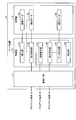
- FIG. 2 is a block diagram illustrating a functional configuration of the server apparatus according to the first embodiment.
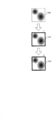
- FIG. 3 is a diagram illustrating an example of the area reception method and the correction reception method.
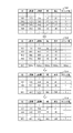
- FIG. 4 is a diagram illustrating an example of generating a merge record.
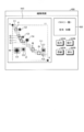
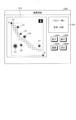
- FIG. 5 is a diagram illustrating an example of the editing screen.
- FIG. 6 is a diagram illustrating an example of the editing screen.
- FIG. 7 is a diagram illustrating an example of the editing screen.
- FIG. 8 is a diagram illustrating a frame setting example before and after correction.
- FIG. 9 is a flowchart illustrating the procedure of the colony count correction process according to the first embodiment.
- FIG. 10 is a diagram illustrating an application example of the area receiving method.
- FIG. 11 is a diagram illustrating a hardware configuration example of a computer that executes a correction program according to the first and second embodiments.
- FIG. 1 is a diagram illustrating a configuration of a colony counting support system 1 according to the first embodiment.
- the colony counting support system 1 shown in FIG. 1 provides a colony counting support service that supports counting of colonies contained in a medium in which bacteria are cultured on a petri dish.
- a petri dish image in which a petri dish in which a colony is cultured is illustrated as an example of a photographed image.
- the colony may be included in the image, and it is not always necessary if the colony is cultured. Petri dishes may not be taken.
- the colony counting support system 1 realizes a correction support process for supporting a correction operation for correcting colony detection data detected on a photographed image of a cultured medium. That is, the colony counting support system 1 accepts correction of the total number of colonies in the area designated on the photographed image of the cultured medium, and the image is calculated from the total number after correction in the area and the number of colonies outside the area. The total colony count result is calculated. Thereby, the man-hour for the correction work is reduced by omitting the correction work for correcting the erroneously detected colonies one by one. This simplifies the process of correcting the number of colonies.
- the colony counting support system 1 accommodates a server device 10 and client terminals 30A to 30C.
- FIG. 1 illustrates three client terminals, the number of client terminals accommodated in the system may be any number.
- client terminal 30 when the devices of the client terminals 30A to 30C are collectively referred to, they may be referred to as “client terminal 30”.
- the server device 10 and the client terminal 30 are connected via the network 5 so that they can communicate with each other.
- the network 5 can employ any type of communication network, such as the Internet (Internet), LAN (Local Area Network), and VPN (Virtual Private Network), whether wired or wireless.
- the server device 10 is a computer that provides the colony counting support service to the client terminal 30.
- the server device 10 may be implemented as a Web server that implements a colony counting support service, or may be implemented as a cloud that provides a colony counting support service through outsourcing.
- the server device 10 can also be implemented by preinstalling or installing a colony counting program provided as package software or online software on a desired computer.
- a client server system is constructed
- the colony counting support system 1 may cause the client terminal 30 to execute the colony counting support service stand-alone.
- the client terminal 30 is a computer that receives the above colony counting support service.
- the client terminal 30 can employ an imaging device itself that can image a petri dish used for a hygiene inspection.
- the client terminal 30 employs a computer capable of storing a petri dish image acquired via the imaging device or the auxiliary storage device in addition to a computer having an imaging device built-in, attached or connected by communication.
- You can also
- a dedicated imaging apparatus that can capture a petri dish while changing the distance and direction for capturing the petri dish in which the colony is cultured, and further, the type of illumination applied to the petri dish is employed. be able to.
- a general-purpose computer equipped with an imaging device as a standard can be used.
- a mobile communication terminal such as PHS or PDA, a tablet terminal, or the like
- PHS is an abbreviation for “Personal Handyphone System”
- PDA is an abbreviation for “Personal Digital Assistants”.
- the hygiene inspection is performed by an inspector who belongs to an inspection department of a factory for food or the like. Such an inspector collects a part of the food from the food as a specimen and cultivates a bacterial colony in the petri dish in the following manner in order to perform a hygiene inspection on the food shipped from the factory.
- sample identification information for example, a sample number assigned to each sample is given to the collected sample.
- the inspector puts the specimen in a petri dish together with a dissolved medium in the case of the pour method, for example, in accordance with various inspection items such as Staphylococcus aureus, Escherichia coli, and general live bacteria.
- various inspection items such as Staphylococcus aureus, Escherichia coli, and general live bacteria.
- the same specimen number is written on the petri dish lid so that the test items to be performed between the same specimens can be discriminated in the petri dishes in which the same specimen is cultured.
- the inspector cultivates the bacteria in the petri dish by keeping the petri dish in an incubator for a predetermined period according to the inspection item, for example, about 48 hours if it is a general living microbe.
- a part of the sample collected from the food can be stored frozen in preparation for retesting.
- the inspector places the petri dish at a predetermined photographing position to cause the imaging apparatus to pick up the petri dish image.
- the petri image is uploaded to the server device 10 at a predetermined opportunity. For example, uploading may be executed every time a petri dish image is taken, or uploading may be executed at a certain cycle or regular time.
- the inspector designates the colony detection result and the count result executed by the server device 10 by specifying the sample number desired to view the colony detection result and the count result via the client terminal 30. 30 can be displayed.
- the inspector can determine the presence or absence of colonies and the number of colonies, and as a result, can determine whether the hygiene inspection is OK or NG.
- whether the test is OK or NG is determined based on whether the total number of colonies in the petri dish is equal to or greater than a predetermined threshold, such as desoxycholate, which is a type of coliform bacteria, or general viable bacteria. Assume a case.
- FIG. 2 is a block diagram illustrating a functional configuration of the server apparatus 10 according to the first embodiment.
- the server device 10 includes a communication I / F (InterFace) unit 11, a storage unit 13, and a control unit 15.
- the server device 10 may include various functional units included in a known computer other than the functional units illustrated in FIG. 2, for example, functional units such as various input / output devices, audio output devices, and imaging devices. Absent.
- the communication I / F unit 11 is an interface for performing communication control with another device, for example, the client terminal 30.
- a network interface card such as a LAN card can be employed.
- the communication I / F unit 11 receives from the client terminal 30 an edit request for a petri dish image, a colony detection result, an operation for designating an area in the petri dish image, or an operation for correcting the total number of colonies in the area.
- the communication I / F unit 11 includes a correction screen for correcting the colony detection result and the correction screen including the colony counting result of the whole petri image and the correction result of the total number of colonies in the area. Or send to 30.
- the storage unit 13 includes various programs such as an OS (Operating System) executed by the control unit 15, middleware, and application programs including a colony counting support program that implements the above-described colony counting support service, and data used for the programs.
- OS Operating System
- middleware middleware
- application programs including a colony counting support program that implements the above-described colony counting support service, and data used for the programs.
- the storage unit 13 is implemented as a main storage device in the server device 10.
- various semiconductor memory elements such as RAM (Random Access Memory) and flash memory can be employed for the storage unit 13.
- the storage unit 13 can also be implemented as an auxiliary storage device.
- an HDD Hard Disk Drive
- an SSD Solid State Drive
- an optical disk or the like can be employed.
- the storage unit 13 stores image data 13a, detection data 13b, correction data 13c, and the like as an example of data used in a program executed by the control unit 15.
- the detection data 13b and the correction data 13c other than the image data 13a will be described together in the description of the control unit 15.
- the storage unit 13 can also store other electronic data, for example, the schedule of the hygiene inspection, the correspondence between the petri dish and the hygiene test, and the test result for each petri dish. Needless to say.
- the image data 13a is data relating to an image such as a petri dish image.
- the petri dish received from the client terminal 30 is stored in the storage unit 13.
- various items such as an imaging date and time, a specimen number, a type of sanitary examination, and identification information of an inspector who has taken the petri dish image can be set as metadata.
- such metadata can be automatically set based on the petri dish imaging order, or can be manually set by an inspector.
- the control unit 15 has an internal memory for storing various programs and control data, and executes various processes using these.
- control unit 15 is implemented as a central processing unit, a so-called CPU (Central Processing Unit).
- CPU Central Processing Unit
- the control unit 15 does not necessarily have to be implemented as a central processing unit, and may be implemented as an MPU (Micro Processing Unit).
- MPU Micro Processing Unit
- the control unit 15 can be realized by hard wired logic such as ASIC (Application Specific Integrated Circuit) or FPGA (Field Programmable Gate Array).
- the control unit 15 virtually implements the following processing unit by executing various programs.
- the control unit 15 includes a detection unit 15a, a display control unit 15b, an area reception unit 15c, a correction reception unit 15d, a calculation unit 15e, and a data generation unit 15f.
- the detection unit 15a is a processing unit that detects colonies from a petri dish image.
- the detection unit 15 a reads out the image data 13 a of the petri dish image from the storage unit 13 every time the petri image is registered in the storage unit 13.
- the detection part 15a calculates the detection reference of a colony from the distribution tendency of the luminance value in a petri dish image. For example, the detection unit 15a generates a histogram of luminance values by referring to the luminance value of each pixel included in the petri dish image.
- the detection unit 15a calculates the luminance value having the highest frequency in the luminance value histogram as the luminance value representing the background portion such as the culture medium. Then, the detection unit 15a calculates a threshold value to be compared with the luminance difference between the luminance value of the pixel in the petri dish image and the representative luminance value of the background portion.
- the detection unit 15a After the colony detection criterion is calculated in this way, the detection unit 15a generates a binarized image from the petri image according to the colony detection criterion.
- the detection unit 15a can generate a binarized image by executing the following process for each pixel included in the petri image. For example, the detection unit 15a determines whether the luminance difference between the luminance value of the pixel in the petri dish image and the representative luminance value of the background portion is equal to or greater than a threshold value. At this time, if the luminance difference is less than the threshold, it can be considered that the pixel corresponds to the background. In this case, the detection unit 15a sets the pixel value of the pixel to “0”, that is, “black”.
- the detection unit 15a sets the pixel value of the pixel to “1”, that is, “white”. In this way, a binarized image of the petri dish image can be obtained by executing the above binarization for each pixel in the petri dish image.
- the detection unit 15a estimates the presence of a colony included in the binarized image from the binarized image generated previously. For example, the detection unit 15a performs edge detection on the binarized image. And the detection part 15a labels the edge or group of edges which forms the outline of the shape similar to the shape which the colony made into a test
- the detection unit 15a determines a colony candidate when the number of white pixels included in the colony candidate is within a predetermined appropriate range, for example, an area defined by the type of colony to be inspected. Can be detected as a colony. In this way, colonies present in the petri image are recognized.
- the detection unit 15a registers detection data 13b in which the position of the colony is associated with each colony included in the petri image in the storage unit 13 as a colony detection result.
- the position of the colony it can be defined by one representative point representing the colony among the pixels forming the colony on the petri dish image, for example, the center of gravity or the center.
- the position of the colony can also be defined as follows.
- the position of the colony can be defined by the position and size of a frame that can be assumed to include each pixel forming the outline of the colony obtained by image processing. In the following, a case where the shape is a rectangle is illustrated as an example of the shape of the frame, but other shapes such as a polygon, an ellipse, and a circle may be adopted as the shape of the frame.
- the detection data 13b for example, data in which an ID (IDentifier), an x coordinate, ay coordinate, a width, a height, and the number of colonies are associated can be employed.
- ID refers to colony identification information. For example, a number uniquely identifying each colony detected by the detection unit 15a is assigned to each colony.
- x coordinate and y coordinate indicate the coordinates of the representative point of the frame on the petri dish image.
- “Width” refers to the width of the frame, and for example, the number of pixels in the x direction (horizontal direction) of the image is used.
- “Height” indicates the height of the frame, and for example, the number of pixels in the y direction (vertical direction) of the image is used. Furthermore, “the number of colonies” refers to the number of colonies included in the frame. For example, at the stage where colonies are detected, one frame is associated with one colony, so “1” is stored as the value of the number of colonies.
- the display control unit 15b is a processing unit that performs display control on the client terminal 30.
- the display control unit 15b when receiving an edit request for a colony detection result, causes the client terminal 30 to display an edit screen for correcting the colony detection result by performing the following processing. That is, the display control unit 15b reads the petri dish image corresponding to the specimen number designated by the editing request from the petri dish included in the image data 13a stored in the storage unit 13. At the same time, the display control unit 15b reads out colony detection data associated with the petri dish image of the detection data 13b stored in the storage unit 13.
- the display control unit 15b determines the position and size determined by the detection data read from the storage unit 13 for each colony included in the entire petri dish image read from the storage unit 13 or a partial image in which a part of the petri dish image is enlarged.
- the frame is displayed in accordance with the above.
- the display control unit 15b calculates the count result of the colonies included in the entire petri image by summing the number of colonies of each record included in the colony detection data read from the storage unit 13.
- the display control unit 15b displays a correction screen for the detection result of the colony displayed with the frame superimposed on the position where the colony is detected on the petri image or the partial image, and counts of colonies included in the whole petri image.
- An editing screen including the result counting result screen is displayed on the client terminal 30.
- the display control unit 15b overlaps the outer frame forming the outline of the area on the correction area, and the client terminal 30. To display. At this time, the display control unit 15b displays the total number of colonies included in the region whose designation is received by the region receiving unit 15c in the vicinity of the outer frame of the region. Also, the display control unit 15b receives a correction operation for the total number of colonies in the area, for example, an operation for incrementing or decrementing the total number or inputting a numerical value for the total number when the correction receiving unit 15d accepts the designation. The total number of colonies in the area displayed in the vicinity of the outer frame of the area that has received is updated to the total number corrected by the correction operation.
- the area accepting unit 15c is a processing unit that accepts designation of an area on the correction screen included in the editing screen.
- the area receiving unit 15c selects one of the frames included in the correction screen through the pointing device connected to the client terminal 30, thereby specifying the range included in the frame as the area specification. Can be accepted.
- the selection of the frame is not limited to an operation on the pointing device, for example, left click, and the designation of the region can be accepted by a combination of the Tab key, the control key and the arrow key.
- the area receiving unit 15c can receive the designation of the area by accepting the drag and drop range designation through the pointing device connected to the client terminal 30.
- the area receiving unit 15c causes a representative point, width, and height of an area to be input as an example of information that defines the shape and size of the area through an input device such as a keyboard connected to the client terminal 30.
- an input device such as a keyboard connected to the client terminal 30.
- it is possible to accept the designation of the area.
- the area was specified by the input device alone was illustrated here, as will be described later, when the input device is formed as a touch panel by being integrated with the display device, the specification of the area is input by drawing. It is good as well.
- the correction accepting unit 15d is a processing unit that accepts corrections to the total number of colonies located in the region for which the region accepting unit 15c accepts designation.
- the correction receiving unit 15d can receive a correction operation such as increment or decrement with respect to the total number of colonies in the area.
- a correction operation such as increment or decrement with respect to the total number of colonies in the area.
- the correction accepting unit 15d accepts an increment operation by a plus (+) key operation or performs a decrement operation by a minus ( ⁇ ) key operation. You can accept.
- the correction reception unit 15d can directly input the value of the total number after correction by inputting a numeric key or a combination of numeric keys.
- the correction accepting unit 15d accepts an increment operation when the mouse wheel is rotated in the forward direction, that is, in the backward direction as viewed from the user.
- the decrement operation can be accepted when the mouse wheel is rotated in the backward direction, that is, in the forward direction as viewed from the user. Note that since the mouse wheel is also used for scrolling the screen, pressing the control key may be added to the condition for the correction operation.
- FIG. 3 is a diagram illustrating an example of the area reception method and the correction reception method.
- FIG. 3 shows an example of a correction screen extracted from the editing screen.
- the correction screen shows a frame 200 at a position where a colony is detected in a partial image obtained by enlarging a part of the petri dish image. ing. Further, FIG. 3 illustrates a frame 200 when two colonies that are close to each other are erroneously detected as one colony.
- FIG. 3 shows a case where frame selection is accepted as an example of area designation.
- the frame 210 is displayed by changing the line display form of the frame 200 from a thin line to a thick line.
- the display of the frame 210 notifies that the input focus is in the area where the line of the frame is a thick line and the standby state for accepting the correction operation is entered.
- the number of colonies included in the area is displayed in the vicinity of the designated area.
- “1” is displayed as the total number of colonies in the vicinity of the area, that is, near the upper right vertex of the frame 210 in the figure.
- the total number of colonies displayed near the top right corner of the frame 210 is the total number “1” before correction.
- the total number after correction is updated to “2”.
- the calculation unit 15e calculates the colony count result for the petri image based on the corrected total number of colonies located within the region that the region accepting unit 15c accepted the designation and the number of colonies located outside the region. A processing unit to calculate.
- the calculation unit 15e and the total number after correction in the area increased or decreased by the correction operation and the colony read from the storage unit 13 The total number of colonies outside the area obtained by summing the number of colonies in the records outside the area where the coordinates of the representative points are excluded from the records included in the detection data is added to the petri dish. Calculate the total number of colonies for the entire image.
- the data generation unit 15f is a processing unit that generates the correction data 13c for the colony detection result by reflecting the correction result in the detection data 13b.
- the data generation unit 15f determines whether or not there are a plurality of colony detection results included in the region when the region reception unit 15c receives the designation of the region. For example, the data generation unit 15f determines whether or not there are a plurality of records in which the colony detection data read from the storage unit 13 includes colony positions, for example, the coordinates of the representative points of the frame in the region. Determine whether.
- the data generation unit 15f when there are a plurality of records in which the coordinates of the representative points of the frame are present in the region, the data generation unit 15f generates a merge record for merging and recording the colony detection results in the region. That is, one colony is managed by one record at the stage where colonies are detected from the petri image, but the number of colonies included in one area is managed by one record at the stage where the area is designated. As a result, the detection results of the colonies in the region are merged.
- the data generation unit 15f assigns an ID as an example of identification information of the area to the area whose designation is received by the area reception unit 15c, and the merge record includes the ID of the area. Is newly generated.
- the data generation unit 15f may set the numbering system of IDs assigned to colonies and the numbering system of IDs assigned to areas different from each other.
- the data generation unit 15f sets the range of the area whose designation is received by the area reception unit 15c in the merge record. For example, the data generation unit 15f sets the width and height of the area together with the representative point of the area, for example, the coordinates of the upper left vertex forming the area, in the merge record.
- the data generation unit 15f includes the colonies in the area obtained by summing the number of colonies of the record in which the coordinates of the representative point of the colony are included in the area among the records included in the colony detection data read from the storage unit 13. Is set in the merge record. At the same time, the data generation unit 15f deletes a record in which the coordinates of the representative point of the colony are included in the area from among the records included in the colony detection data read from the storage unit 13. As a result, the colony count results of the petri dish image as a whole are matched, and the number of colonies where erroneous detection occurs is merged and managed in units of areas.
- the data generation unit 15f when the correction receiving unit 15d receives a correction operation such as increment or decrement with respect to the total number of colonies in the area, the colony included in the record of the area The number is updated to the corrected total number corresponding to the correction operation. Thereafter, when the data generation unit 15f receives an editing end operation through the client terminal 30, the data generation unit 15f corrects the detection data after the correction operation is performed on the colony detection data read from the storage unit 13 with respect to the colony detection result. Data 13c is registered in the storage unit 13.
- FIG. 4 is a diagram showing an example of generating a record for merging.
- the range including the coordinates of the representative points of the ID “102” and ID “103” of the colony detection data 13b1 read from the storage unit 13 is designated as an area. Illustrated. When the designation of such an area is received, a plurality of colony detection results relating to ID “102” and ID “103” are included in the area.
- a merge record including the ID “901” of the area is newly generated. At this stage, only the ID value is stored, and a NULL value indicating that the data value is blank is stored in the other items.
- the coordinates of the upper left vertex of the region with respect to the x coordinate and y coordinate fields among the fields included in the merge record Is set, and the number of pixels in the x direction “486” and the number of pixels in the y direction “590” are set for the width and height fields.
- the total number “2” of colonies in the area obtained by summing up the number of colonies in the records is set.
- the records of ID “102” and ID “103” in which the coordinates of the representative point of the colony are included in the area are deleted from the records of the colony detection data 13b2.
- the colony number field of the fields included in the merge record is not corrected.
- the total number “2” is updated to the corrected total number “3”.
- FIGS. 5 to 7 are diagrams showing examples of the edit screen.
- the editing screen 300 shown in FIG. 5 includes a colony detection result correction screen 310 in which a frame indicating colony detection is superimposed on a position where a colony is detected on a partial image of the petri image, and the entire petri image.
- the count result screen 320 of the count result of the included colony is included.
- the editing screen 300 further includes an enlargement button 330A for enlarging the partial image displayed on the correction screen 310, a reduction button 330B for reducing the partial image displayed on the correction screen 310, and the correction result for the colony detection data.
- a GUI component such as a registration button 340A to be registered as 13c and a screen 340B that is displayed immediately before the editing screen without registering the correction data 13c, for example, a button 340B for returning to the main screen or the like, is included.
- the functions of the enlarge button, the reduce button, the register button, and the return button shown in FIGS. 6 and 7 are the same as those shown in FIG.
- the correction screen 310 shown in FIG. 5 includes a colony C1 that is elongated from the upper left to the lower right of the correction screen 310 and substantially circular colonies C2 to C7. Further, frames f1 to f11 are displayed as colony detection results. However, while the frames f6, f7 and f11 are set corresponding to the colonies C5, C6 and C7, a plurality of frames f1 to f5 and f8 to f10 are erroneously set to the colony C1 which is one colony. ing.
- the correction screen 410 shown in FIG. 6 shows an example in which the drop operation is performed at the point E after the drag operation is continued until the drag operation starts at the point S and moves to the point E.
- the area designated as a result of such drag and drop is the range indicated by the alternate long and short dash line.
- the detection result of the colonies included in the area that is, the number of colonies “11” corresponding to the frames f1 to f11 is displayed.
- the editing screen 400 shown in FIG. 6 enters a standby state for accepting a correction operation.
- a minus ( ⁇ ) key operation is accepted four times as an operation of decrementing the number of colonies “4” which is more than the actual number of colonies “7”.
- the screen transitions to an editing screen 500 shown in FIG.
- the total number of colonies in the area displayed in the vicinity of the upper right vertex of the area is shown in the correction screen 510 of FIG. 7 from the colony number “11” before correction shown in the correction screen 410 of FIG.
- the number of colonies after correction is updated to “7”.
- the total number “7” after correction in the area subtracted by the correction operation and the record in which the coordinates of the representative point are in the area among the records included in the colony detection data read from the storage unit 13 The total number “47” of the colonies outside the area obtained by summing the number of colonies held by the records outside the removed area is totaled. Accordingly, the display of the total number of colonies of the entire petri dish image is updated from the total number “58” shown in the counting result screen 420 of FIG. 6 to the total number “54” shown in the counting result screen 520 of FIG. Is done.
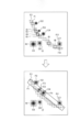
- FIG. 8 is a diagram illustrating a frame setting example before and after correction.
- FIG. 8 shows a setting example of a frame before correction and a frame after correction when the colony detection results shown in FIGS. 5 to 7 are corrected using the conventional technique.
- four deletions of frames F1 to F4 are performed after eight deletion operations are performed to delete each of the frames f1 to f5 and f8 to f10 that have been erroneously detected.
- An additional operation for setting and adding the shape and size of the frame is performed.
- FIG. 9 is a flowchart illustrating the procedure of the colony count correction process according to the first embodiment. This process is started when an edit request for the colony detection result is received. As illustrated in FIG. 9, the display control unit 15 b causes the client terminal 30 to display an edit screen for correcting the colony detection result corresponding to the sample number specified in the edit request (step S ⁇ b> 101). For example, the editing screen includes the correction screen and the counting result screen.
- step S102 the data generation unit 15f determines whether there are a plurality of colony detection results included in the area for which the designation is accepted. Is determined (step S103). At this time, if the coordinate of the representative point of the frame is one or less records in the area (No in step S103), the process proceeds to step S108. If no area designation has been received (No in step S102), the system waits for the area designation to be accepted.
- the data generation unit 15f adopts an ID as an example of identification information of the area in the area where the designation is accepted.
- the merge record for merging and recording the colony detection results in the area including the ID of the area is generated (step S104).
- the data generation unit 15f sets the range of the area for which designation is accepted in step S103 in the merge record (step S105). Furthermore, the data generation unit 15f includes the colonies in the area obtained by summing the number of colonies of the record in which the coordinates of the representative point of the colony are included in the area among the records included in the colony detection data read from the storage unit 13. Is set in the merge record (step S106). At the same time, the data generation unit 15f deletes the record in which the coordinates of the representative point of the colony are included in the area from among the records of the colony detection data read from the storage unit 13 (step S107).
- step S108 when a correction operation such as increment or decrement for the total number of colonies in the area is accepted (Yes in step S108), the data generation unit 15f changes the number of colonies held in the record of the area after the correction corresponding to the correction operation. The total number is updated (step S109). If the correction operation has not been accepted (No at step S108), the process from step S109 to step S111 is skipped, and the process proceeds to step S112.
- the calculation unit 15e has the total number after correction in the area increased or decreased by the correction operation in step S108 and the coordinates of the representative point among the records included in the colony detection data read from the storage unit 13.
- the total number of colonies in the entire petri dish image is calculated by totaling the total number of colonies outside the area obtained by summing the number of colonies in the records outside the area from which the records in the area are removed (step S110). ).
- the display control unit 15b updates the display of the total number of colonies in the area displayed in the vicinity of the outer frame of the area received in step S102 to the total number corrected by the correction operation, and the petri image The display of the total number of all colonies is updated to the total number calculated in step S110 (step S111).
- step S113 when another operation for removing the input focus from the area specified in step S102 is accepted (Yes in step S112), it is determined whether the other operation is an editing end operation (step S113). At this time, if it is not an editing end operation (step S113 No), the process returns to step S102. In addition, when other operation is not received (step S112 No), it returns to the process of step S108.
- the data generation unit 15f uses the detection data after the correction operation is performed on the colony detection data read from the storage unit 13 as the correction data for the colony detection result. 13c is registered in the storage unit 13 (step S114), and the process is terminated.
- the server device 10 accepts the correction of the total number of colonies in the area designated on the image of the culture medium after colony culture, and the corrected total number and area in the area The colony counting result of the entire image is calculated from the number of outside colonies. Therefore, according to the server apparatus 10 which concerns on a present Example, the correction operation
- the server apparatus 10 collects the movement trajectory of the pointing device and the movement trajectory of the fingers and the touch pen with respect to the touch panel.
- the server device 10 can also designate an area of an arbitrary shape by setting the previous movement trajectory in the merge record as the area range.
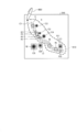
- FIG. 10 is a diagram showing an application example of the area receiving method.
- the area included in the movement trajectory 610 is excluded except for the detection results of the frames f6 and f7 where the colonies C5 and C6 have been correctly detected. Can be specified.
- the total number of colonies in the area is displayed in the vicinity of the area as the total “9” of the frames f1 to f5 and the frames f8 to f11. As a result, it is possible to suppress a situation in which a frame having a correct detection result is included in the area where the designation is accepted, and thus it is possible to more effectively simplify the colony number correction operation.
- the server device 10 obtains a likelihood indicating the likelihood of being a colony for each colony candidate, displays a candidate having a likelihood equal to or higher than a threshold as a colony in a solid frame, and sets a candidate having a likelihood lower than the threshold as unknown It can also be displayed in a dotted frame.
- the unknown can be added as a colony through a predetermined operation, for example, a double click.
- Example 1 the case where there is one bacterial species of colonies detected from the petri image is exemplified, but there may be a plurality of colony bacterial species.
- a fungus species item may be added to the detection data 13b and the correction data 13c, and the process shown in FIG.
- the server device 10 accepts designation of a bacterial species that corrects the total number of colonies in the area, and increments or decrements the total number of colonies of the bacterial species that have accepted the designation. Is accepted as a correction operation.
- the server device 10 executes a correction operation reception and a recalculation of the total number of colonies of the entire image for each bacterial species.
- the total number of colonies in the region and the total number of colonies in the entire petri dish image can be displayed for each bacterial type, and the total number of colonies for all bacterial species is also displayed in the region or the entire image. You can also
- each component of each illustrated apparatus does not necessarily need to be physically configured as illustrated.
- the specific form of distribution / integration of each device is not limited to that shown in the figure, and all or a part thereof may be functionally or physically distributed or arbitrarily distributed in arbitrary units according to various loads or usage conditions.
- FIG. 1 illustrates a case in which a series of processing from reception of a petri dish to colony detection and correction is provided as a colony counting support service. It is also possible to execute the process until the correction of the colony by another computer. Furthermore, colony detection and colony correction can be executed by another computer. In the example of FIG.
- the case where a client server system is constructed is illustrated, but a computer having each functional unit in the control unit 15 shown in FIG. 2 can be operated in a stand-alone manner.
- the client terminal 30 may have each function unit in the control unit 15 shown in FIG.
- FIG. 11 is a diagram illustrating a hardware configuration example of a computer that executes the correction program according to the first and second embodiments.
- the computer 100 includes an operation unit 110 a, a speaker 110 b, a camera 110 c, a display 120, and a communication unit 130. Further, the computer 100 includes a CPU 150, a ROM 160, an HDD 170, and a RAM 180. These units 110 to 180 are connected via a bus 140.
- the HDD 170 stores a correction program 170a that exhibits the same functions as those of the area reception unit 15c, the correction reception unit 15d, and the calculation unit 15e described in the first embodiment.
- the correction program 170a may be integrated or separated as in the case of the constituent elements of the display control unit 15b, the area reception unit 15c, the correction reception unit 15d, the calculation unit 15e, and the data generation unit 15f illustrated in FIG. That is, the HDD 170 does not necessarily have to store all the data shown in the first embodiment, and data used for processing may be stored in the HDD 170.
- the CPU 150 reads the correction program 170a from the HDD 170 and develops it in the RAM 180.
- the correction program 170a functions as a correction process 180a as shown in FIG.
- the correction process 180a expands various data read from the HDD 170 in an area allocated to the correction process 180a in the storage area of the RAM 180, and executes various processes using the expanded various data.
- the process shown in FIG. 9 is included as an example of the process executed by the correction process 180a.
- the CPU 150 does not necessarily operate all the processing units described in the first embodiment, and the processing unit corresponding to the process to be executed may be virtually realized.
- correction program 170a may not necessarily be stored in the HDD 170 or the ROM 160 from the beginning.
- each program is stored in a “portable physical medium” such as a flexible disk inserted into the computer 100, so-called FD, CD-ROM, DVD disk, magneto-optical disk, or IC card. Then, the computer 100 may acquire and execute each program from these portable physical media.
- each program is stored in another computer or server device connected to the computer 100 via a public line, the Internet, a LAN, a WAN, etc., and the computer 100 acquires and executes each program from these. It may be.
Landscapes
- Chemical & Material Sciences (AREA)
- Organic Chemistry (AREA)
- Health & Medical Sciences (AREA)
- Life Sciences & Earth Sciences (AREA)
- Engineering & Computer Science (AREA)
- Bioinformatics & Cheminformatics (AREA)
- Zoology (AREA)
- Wood Science & Technology (AREA)
- Microbiology (AREA)
- Sustainable Development (AREA)
- Biotechnology (AREA)
- Biomedical Technology (AREA)
- Biochemistry (AREA)
- General Engineering & Computer Science (AREA)
- General Health & Medical Sciences (AREA)
- Genetics & Genomics (AREA)
- Analytical Chemistry (AREA)
- Apparatus Associated With Microorganisms And Enzymes (AREA)
Abstract
サーバ装置(10)は、細菌が培養された培地の撮影画像上に、該撮影画像から検出されたコロニーの位置を示す情報を表示する表示画像について、領域の指定を受け付ける処理と、受け付けた領域内に位置するコロニーの合計数に対する修正を受け付ける処理と、受け付けた領域内に位置するコロニーについての修正後の合計数と、領域外に位置するコロニーの数とに基づいて、画像に対するコロニーの計数結果を算出する処理とを実行する。
Description
本発明は、コロニー数の修正方法、修正プログラム及び修正装置に関する。
食品の製造施設等では、菌類の混入を検査する衛生検査が行われる。例えば、食品の一部が採取された検体をシャーレ上に準備された培地に塗抹または混釈し、シャーレ上で検体に含まれる細菌を適温に保った上で所定の期間にわたって培養する。その上で、培養によってシャーレ上に形成されたコロニーを計数することで衛生検査が実施される。
かかるコロニーの計数に画像処理が用いられる場合がある。例えば、細菌が培養済の培地の撮影画像から画像処理により検出されたコロニーを計数し、その計数結果を出力することにより、コロニーの計数を支援する。
ところが、画像処理には、様々な原因によって誤検出が発生する場合があるので、培養済の培地の撮像画像から必ずしもコロニーを正確に検出できるとは限らない。例えば、複数のコロニーが培地上で結合または近接する場合、互いのコロニーが結合または近接する部分の境界が画像上で不鮮明となり、1つのコロニーとして誤検出される場合がある。また、1つのコロニーが検査の対象とする菌種が持つ標準のサイズよりも広がって繁殖する場合、その面積の大きさが原因となって1つのコロニーが複数のコロニーと誤検出される場合がある。さらに、培養途中の段階では、薬剤に対する生菌の反応が不十分となることもあり、この結果、コロニーの着色が薄くなり、撮像画像からコロニーとして検出できない場合もある。
このことから、作業者が正確かつ速やかにコロニーの個数を求めることを支援するのを目的とするコロニー計数支援装置が提案されている。
このコロニー計数支援装置が作業者に提示する画面には、コロニー計数支援装置により自動で検出されたコロニーの位置や数に基づいて作業者が編集したコロニーの位置や数を示す画像が撮像画像に重ねて表示される手動検出結果表示領域が含まれる。この手動検出結果表示領域には、検出されたコロニーもしくは作業者により追加されたコロニーの撮像画像上における位置を作業者に提示するための手動検出位置マーカ、例えば撮像画像上に表示されたコロニーの重心を交点とする十字型の枠状の画像をさらに含む。
このような表示の下、コロニー計数支援装置は、手動検出結果表示領域上における手動検出位置マークの追加位置の指定を含む追加指示を受け付けたり、手動検出結果表示領域に表示されている削除対象の手動検出位置マークの指定を含む削除指示を受け付けたりする。
しかしながら、上記の技術では、コロニー数の修正作業が煩雑化する場合がある。
すなわち、上記のコロニー計数支援装置では、上記の追加指示により検出漏れのコロニーを追加したり、上記の削除指示により余分に検出されたコロニーを削除したりといった修正作業が行われる。ところが、作業者にコロニーの撮像画像を目視させる目的の一側面は、あくまで撮像画像全体のコロニーの合計数を確認させるためであるにもかかわらず、誤検出されたコロニーを追加指示または削除指示により1つずつ修正させるのは修正作業の煩雑化の一因となる。そうであるからと言って、撮像画像全体のコロニーの合計数に絞って結果の数字を修正すればよいという訳でもない。なぜなら、事後に修正作業の是非を検分できるように、修正作業の内容が確認できる状態で撮像画像中のコロニーの位置情報を残しておかなければ作業者の確認及び衛生検査の品質管理を行う場合に支障が出る可能性もあるからである。
1つの側面では、本発明は、コロニー数の修正作業を簡素化できるコロニー数の修正方法、修正プログラム及び修正装置を提供することを目的とする。
一態様のコロニー数の修正方法は、コンピュータに、細菌が培養された培地の撮影画像上に、該撮影画像から検出されたコロニーの位置を示す情報を表示する表示画像について、領域の指定を受け付ける処理と、受け付けた前記領域内に位置するコロニーの合計数に対する修正を受け付ける処理と、受け付けた前記領域内に位置するコロニーについての修正後の合計数と、前記領域外に位置するコロニーの数とに基づいて、前記画像に対するコロニーの計数結果を算出する処理と、を実行させる。
コロニー数の修正作業を簡素化できる。
以下に添付図面を参照して本願に係るコロニー数の修正方法、修正プログラム及び修正装置について説明する。なお、この実施例は開示の技術を限定するものではない。そして、各実施例は、処理内容を矛盾させない範囲で適宜組み合わせることが可能である。
[システム構成]
図1は、実施例1に係るコロニー計数支援システム1の構成を示す図である。図1に示すコロニー計数支援システム1は、細菌がシャーレ上に培養された培地に含まれるコロニーの計数を支援するコロニー計数支援サービスを提供するものである。なお、以下では、撮影画像の一例として、コロニーが培養されたシャーレが撮影されたシャーレ画像を例示するが、画像内にコロニーが含まれていればよく、コロニーが培養される環境であれば必ずしもシャーレが撮影されずともよい。
図1は、実施例1に係るコロニー計数支援システム1の構成を示す図である。図1に示すコロニー計数支援システム1は、細菌がシャーレ上に培養された培地に含まれるコロニーの計数を支援するコロニー計数支援サービスを提供するものである。なお、以下では、撮影画像の一例として、コロニーが培養されたシャーレが撮影されたシャーレ画像を例示するが、画像内にコロニーが含まれていればよく、コロニーが培養される環境であれば必ずしもシャーレが撮影されずともよい。
かかるコロニー計数支援サービスの一環として、コロニー計数支援システム1は、培養済の培地の撮影画像上で検出されるコロニーの検出データを修正する修正作業を支援する修正支援処理を実現する。すなわち、コロニー計数支援システム1は、培養済の培地の撮影画像上で指定された領域内のコロニーの合計数の修正を受け付け、領域内の修正後の合計数と領域外のコロニーの数から画像全体のコロニーの計数結果を算出する。これによって、誤検出されたコロニーを1つずつ修正する修正作業を省くことにより修正作業の工数を低減する。もって、コロニー数の修正作業を簡素化する。
図1に示すように、コロニー計数支援システム1には、サーバ装置10と、クライアント端末30A~30Cとが収容される。図1には、3つのクライアント端末を図示したが、システムに収容されるクライアント端末の数は任意の数であってかまわない。なお、以下では、クライアント端末30A~30Cの各装置を総称する場合には、「クライアント端末30」と記載する場合がある。
これらサーバ装置10及びクライアント端末30の間は、ネットワーク5を介して相互に通信可能に接続される。かかるネットワーク5には、有線または無線を問わず、インターネット(Internet)、LAN(Local Area Network)やVPN(Virtual Private Network)などの任意の種類の通信網を採用できる。
サーバ装置10は、上記のコロニー計数支援サービスをクライアント端末30に提供するコンピュータである。
一実施形態としては、サーバ装置10は、コロニー計数支援サービスを実現するWebサーバとして実装することとしてもよいし、また、コロニー計数支援サービスをアウトソーシングにより提供するクラウドとして実装することもできる。また、サーバ装置10は、パッケージソフトウェアやオンラインソフトウェアとして提供されるコロニー計数プログラムを所望のコンピュータにプリインストール又はインストールさせることによっても実装できる。なお、ここでは、コロニー計数支援システム1の一例として、クライアントサーバシステムが構築される場合を例示するが、必ずしもクライアントサーバシステムとして実装されずともよい。例えば、コロニー計数支援システム1は、クライアント端末30にコロニー計数支援サービスをスタンドアローンで実行させることとしてもかまわない。
クライアント端末30は、上記のコロニー計数支援サービスの提供を受けるコンピュータである。
一実施形態として、クライアント端末30には、衛生検査に使用するシャーレを撮像できる撮像装置そのものを採用できる。他の実施形態として、クライアント端末30には、撮像装置が内蔵、付設もしくは通信によって接続されるコンピュータの他、撮像装置もしくは補助記憶装置を経由して取得されるシャーレ画像を保存可能なコンピュータを採用することもできる。また、上記の撮像装置の一例としては、コロニーが培養されたシャーレを撮影する距離や方向、さらには、シャーレに照射する照明の種類を変更しながらシャーレ画像を撮影できる専用の撮像装置を採用することができる。他の一例としては、撮像装置を標準装備する汎用のコンピュータを用いることもできる。例えば、パーソナルコンピュータを始めとする固定端末の他、スマートフォンを始め、携帯電話機、PHSやPDAなどの移動体通信端末、さらには、タブレット端末などを採用できる。なお、上記のPHSは、「Personal Handyphone System」の略称であり、上記のPDAは、「Personal Digital Assistants」の略称である。
ここで、衛生検査の流れの一例について説明する。例えば、衛生検査は、食品等の工場の検査部門に所属する検査員等によって実施される。かかる検査員は、工場が出荷する食品に衛生検査を実施するために、食品からその一部を検体として採取し、次のような方法でシャーレに細菌のコロニーを培養する。
例えば、衛生検査では、検査員によって食品の一部が検体として採取されるとともに、採取された検体に検体の識別情報、例えば検体ごとに採番される検体番号が付与される。次いで、検査員は、黄色ブドウ球菌、大腸菌や一般生菌などの各種の検査項目にあわせて、検体を、例えば混釈法の場合、溶解させた培地とともにシャーレに入れる。このとき、同一の検体につき同一段階で検体が希釈された複数のシャーレを作成することもできる。また、同一の検体が培養されるシャーレには、同一の検体の間で実施する検査項目が判別できるように、同一の検体番号がシャーレの蓋に記入される。その上で、検査員は、検査項目に合わせた所定の期間、例えば一般生菌であれば48時間程度にわたってインキュベータでシャーレを保温することによってシャーレ内の菌を培養する。なお、食品から採取される検体は、再検査に備えてその一部を冷凍保存しておくこともできる。
このようにして培養がなされた後に、検査員は、所定の撮影位置にシャーレを載置することによって撮像装置にシャーレ画像を撮像させる。かかるシャーレ画像が撮像された場合には、シャーレ画像が所定の契機にサーバ装置10へアップロードされる。例えば、シャーレ画像が撮像される度にアップロードが実行されることとしてもよいし、一定の周期または定期時刻にアップロードが実行されることとしてもよい。その後、検査員は、クライアント端末30を介して、コロニーの検出結果や計数結果の閲覧を希望する検体番号を指定することによって、サーバ装置10によって実行されたコロニーの検出結果や計数結果をクライアント端末30に表示させることができる。これによって、検査員は、コロニーの有無、さらには、コロニー数の多寡を把握できる結果、衛生検査のOKまたはNGを判断することができる。
以下では、衛生検査の一例として、大腸菌群の一種であるデソキシコレートや一般生菌などのように、シャーレ全体のコロニー数が所定の閾値以上であるか否かにより検査のOKまたはNGが判断される場合を想定する。
[サーバ装置10の構成]
図2は、実施例1に係るサーバ装置10の機能的構成を示すブロック図である。図2に示すように、サーバ装置10は、通信I/F(InterFace)部11と、記憶部13と、制御部15とを有する。なお、サーバ装置10は、図2に示した機能部以外にも既知のコンピュータが有する各種の機能部、例えば各種の入出力デバイス、音声出力デバイスや撮像デバイスなどの機能部を有することとしてもかまわない。
図2は、実施例1に係るサーバ装置10の機能的構成を示すブロック図である。図2に示すように、サーバ装置10は、通信I/F(InterFace)部11と、記憶部13と、制御部15とを有する。なお、サーバ装置10は、図2に示した機能部以外にも既知のコンピュータが有する各種の機能部、例えば各種の入出力デバイス、音声出力デバイスや撮像デバイスなどの機能部を有することとしてもかまわない。
このうち、通信I/F部11は、他の装置、例えばクライアント端末30との間で通信制御を行うインタフェースである。かかる通信I/F部11の一態様としては、LANカードなどのネットワークインタフェースカードを採用できる。例えば、通信I/F部11は、クライアント端末30からシャーレ画像、コロニーの検出結果の編集要求、シャーレ画像内の領域の指定操作または領域内のコロニーの合計数の修正操作を受信する。また、通信I/F部11は、コロニーの検出結果を修正するための修正画面や当該修正画面にシャーレ画像全体のコロニーの計数結果及び領域内のコロニーの合計数の修正結果を含めてクライアント端末30へ送信したりする。
記憶部13は、制御部15で実行されるOS(Operating System)を始め、ミドルウェアや上記のコロニー計数支援サービスを実現するコロニー計数支援プログラムを含むアプリケーションプログラムなどの各種のプログラム及びプログラムに用いられるデータを記憶するデバイスである。
一実施形態として、記憶部13は、サーバ装置10における主記憶装置として実装される。例えば、記憶部13には、各種の半導体メモリ素子、例えばRAM(Random Access Memory)やフラッシュメモリを採用できる。また、記憶部13は、補助記憶装置として実装することもできる。この場合、HDD(Hard Disk Drive)、SSD(Solid State Drive)や光ディスクなどを採用できる。
記憶部13は、制御部15で実行されるプログラムに用いられるデータの一例として、画像データ13a、検出データ13b及び修正データ13cなどを記憶する。なお、上記の画像データ13a以外の検出データ13b及び修正データ13cは、制御部15の説明で併せて説明することとする。また、記憶部13には、上記のデータ以外にも、他の電子データ、例えば衛生検査のスケジュール、シャーレと衛生検査の対応関係やシャーレごとの検査結果なども併せて記憶することもできるのは言うまでもない。
画像データ13aは、シャーレ画像などの画像に関するデータである。一実施形態として、記憶部13には、クライアント端末30から受信したシャーレ画像が記憶される。例えば、シャーレ画像には、撮像日時や検体番号を始め、衛生検査の種別やシャーレ画像の撮影を行った検査員の識別情報などの各種の項目をメタデータとして設定することができる。かかるメタデータは、一例として、クライアント端末30でシャーレ画像が撮像される場合に、シャーレの撮影順序等から自動設定することもできるし、検査員によって手動設定させることもできる。
制御部15は、各種のプログラムや制御データを格納する内部メモリを有し、これらによって種々の処理を実行するものである。
一実施形態として、制御部15は、中央処理装置、いわゆるCPU(Central Processing Unit)として実装される。なお、制御部15は、必ずしも中央処理装置として実装されずともよく、MPU(Micro Processing Unit)として実装されることとしてもよい。また、制御部15は、ASIC(Application Specific Integrated Circuit)やFPGA(Field Programmable Gate Array)などのハードワイヤードロジックによっても実現できる。
制御部15は、各種のプログラムを実行することによって下記の処理部を仮想的に実現する。例えば、制御部15は、図2に示すように、検出部15aと、表示制御部15bと、領域受付部15cと、修正受付部15dと、算出部15eと、データ生成部15fとを有する。
検出部15aは、シャーレ画像からコロニーを検出する処理部である。
一実施形態として、検出部15aは、シャーレ画像が記憶部13に登録される度に、当該シャーレ画像の画像データ13aを記憶部13から読み出す。ここでは、シャーレ画像が記憶部13に登録されることを条件に画像データ13aが読み出される場合を例示するが、クライアント端末30からのリクエストを受け付けることを条件に画像データ13aを読み出すこととしてもかまわない。そして、検出部15aは、シャーレ画像における輝度値の分布傾向からコロニーの検出基準を算出する。例えば、検出部15aは、シャーレ画像に含まれる各画素の輝度値を参照することによって輝度値のヒストグラムを生成する。続いて、検出部15aは、輝度値のヒストグラムのうち度数が最も大きい輝度値を培地等の背景部分を代表する輝度値として算出する。そして、検出部15aは、シャーレ画像内の画素の輝度値及び背景部分の代表輝度値の輝度差と比較する閾値を算出する。
このようにコロニーの検出基準が算出された後に、検出部15aは、コロニーの検出基準にしたがって、シャーレ画像から二値化画像を生成する。一例として、検出部15aは、シャーレ画像に含まれる画素ごとに下記の処理を実行することによって二値化画像を生成することができる。例えば、検出部15aは、シャーレ画像内の画素の輝度値と背景部分の代表輝度値との輝度差が閾値以上であるか否かを判定する。このとき、輝度差が閾値未満である場合には、当該画素が背景に相当するとみなすことができる。この場合には、検出部15aは、当該画素の画素値を「0」、すなわち「黒」に設定する。一方、輝度差が閾値以上である場合には、当該画素が背景に相当する可能性が低いことからコロニーの一部と推定することができる。この場合には、検出部15aは、当該画素の画素値を「1」、すなわち「白」に設定する。このように、シャーレ画像内の各画素について上記の二値化を実行することによって当該シャーレ画像の二値化画像を得ることができる。
その後、検出部15aは、先に生成された二値化画像から当該二値化画像に含まれるコロニーの存在を推定する。例えば、検出部15aは、二値化画像にエッジ検出を実行する。そして、検出部15aは、先のエッジ検出によって得られたエッジのうち、検査対象とするコロニーが有する形状と類似する形状の輪郭を形成するエッジもしくはエッジのグループをコロニーの候補としてラベリングする。その上で、検出部15aは、コロニーの候補のうち、検査対象とする種別のコロニーの大きさと類似するコロニーの候補をコロニーとして検出する。一例としては、検出部15aは、コロニーの候補に含まれる白色の画素の数が所定の適正範囲、例えば検査対象とするコロニーの種別によって規定される面積の範囲内である場合に、コロニーの候補をコロニーとして検出することができる。このようにして、シャーレ画像に存在するコロニーが認識される。
その上で、検出部15aは、シャーレ画像に含まれるコロニーごとに当該コロニーの位置が対応付けられた検出データ13bをコロニーの検出結果として記憶部13へ登録する。例えば、コロニーの位置の一例として、シャーレ画像上でコロニーを形成する画素のうち当該コロニーを代表する代表点、例えば重心や中心など1点により定義することもできるが、シャーレ画像の表示時にコロニーの検出結果の視認性を高めるために、次の通りにコロニーの位置を定義することもできる。例えば、コロニーの位置は、画像処理により得られたコロニーの輪郭を形成する各画素を包含すると想定できるフレームの位置及び大きさにより定義することもできる。なお、以下では、フレームの形状の一例として、形状が矩形である場合を例示するが、フレームの形状は多角形、楕円や円などの他の形状が採用されることとしてもかまわない。
より具体的には、検出データ13bには、一例として、ID(IDentifier)、x座標、y座標、幅、高さ及びコロニー数が対応付けられたデータを採用できる。ここで言う「ID」とは、コロニーの識別情報を指し、例えば、検出部15aにより検出された各コロニーを一意に識別する番号が各コロニーに採番される。また、「x座標」及び「y座標」は、シャーレ画像上におけるフレームの代表点の座標を指す。また、「幅」は、フレームの幅を指し、例えば、画像のx方向(水平方向)の画素数が用いられる。また、「高さ」は、フレームの高さを指し、例えば、画像のy方向(鉛直方向)の画素数が用いられる。さらに、「コロニー数」とは、フレーム内に含まれるコロニーの数量を指す。例えば、コロニーの検出が行われた段階では、1つのコロニーにつき1つのフレームが対応付けられるので、コロニー数の値として「1」が格納される。
表示制御部15bは、クライアント端末30に対する表示制御を行う処理部である。
一実施形態として、表示制御部15bは、コロニーの検出結果に対する編集要求を受け付けた場合、下記の処理を行うことにより、コロニーの検出結果を修正する編集画面をクライアント端末30に表示させる。すなわち、表示制御部15bは、記憶部13に記憶された画像データ13aに含まれるシャーレ画像のうち当該編集要求で指定された検体番号に対応するシャーレ画像を読み出す。これと共に、表示制御部15bは、記憶部13に記憶された検出データ13bのうち当該シャーレ画像に対応付けられたコロニーの検出データを読み出す。その後、表示制御部15bは、記憶部13から読み出したシャーレ画像全体またはシャーレ画像の一部が拡大された部分画像に含まれる各コロニーに記憶部13から読み出した検出データで定められた位置及び大きさにしたがってフレームを重ねて表示させる。さらに、表示制御部15bは、記憶部13から読み出されたコロニーの検出データが含む各レコードのコロニー数を合計することにより、シャーレ画像全体に含まれるコロニーの計数結果を算出する。その上で、表示制御部15bは、シャーレ画像上または部分画像上でコロニーが検出された位置にフレームが重ねて表示されたコロニーの検出結果の修正画面と、シャーレ画像全体に含まれるコロニーの計数結果の計数結果画面とを含む編集画面をクライアント端末30へ表示させる。
また、表示制御部15bは、領域受付部15cにより編集画面に含まれる修正画面上で領域の指定が受け付けられた場合、当該領域の輪郭を形成する外枠を修正領域上に重ねてクライアント端末30へ表示させる。このとき、表示制御部15bは、領域受付部15cにより指定が受け付けられた領域に含まれるコロニーの合計数が領域の外枠の近傍に表示させる。また、表示制御部15bは、修正受付部15dにより領域内のコロニーの合計数に対する修正操作、例えば合計数に対するインクリメントまたはデクリメントの操作や合計数の数値入力などの操作が受け付けられた場合、当該指定を受け付けた領域の外枠の近傍に表示された領域内のコロニーの合計数を修正操作による修正後の合計数に更新する。
領域受付部15cは、上記の編集画面に含まれる修正画面上で領域の指定を受け付ける処理部である。
一実施形態として、領域受付部15cは、クライアント端末30に接続されたポインティングデバイスを通じて、修正画面に含まれるフレームのうちいずれか1つのフレームを選択させることにより、フレームが含む範囲を領域の指定として受け付けることができる。なお、フレームの選択は、ポインティングデバイスにおける操作、例えば左クリック等に限定されず、Tabキーやcontrolキー+矢印キーの組合せなどにより領域の指定を受け付けることもできる。
他の実施形態として、領域受付部15cは、クライアント端末30に接続されたポインティングデバイスを通じて、ドラッグ&ドロップの範囲指定を受け付けることにより、領域の指定を受け付けることができる。また、領域受付部15cは、クライアント端末30に接続されたキーボード等の入力デバイスを通じて、領域の形状および大きさを定義する情報の一例として、領域の代表点と、幅および高さとを入力させることにより、領域の指定を受け付けることもできる。なお、ここでは、入力デバイス単独で領域を指定させる場合を例示したが、後述するように、入力デバイスが表示デバイスと一体化させることによりタッチパネルとして形成される場合、領域の指定を描画により入力させることとしてもよい。
修正受付部15dは、領域受付部15cが指定を受け付けた領域内に位置するコロニーの合計数に対する修正を受け付ける処理部である。
一実施形態として、修正受付部15dは、当該領域内のコロニーの合計数に対するインクリメントまたはデクリメントなどの修正操作を受け付けることができる。例えば、クライアント端末30に接続される入力デバイスの一例としてテンキーを用いる場合、修正受付部15dは、プラス(+)のキー操作によりインクリメント操作を受け付けたり、マイナス(-)のキー操作によりデクリメント操作を受け付けたりできる。この他、修正受付部15dは、数字キーまたは数字キーの組合せを入力させることにより、修正後の合計数の値を直接入力させることもできる。また、クライアント端末30に接続される入力デバイスの一例としてマウスを用いる場合、修正受付部15dは、マウスホイールが前方向、すなわちユーザから見て奥の方向へ回転された場合にインクリメント操作を受け付けたり、マウスホイールが後方向、すなわちユーザから見て手前の方向へ回転された場合にデクリメント操作を受け付けたりすることができる。なお、マウスホイールは、画面スクロールにも用いられることから、controlキーが押下されることを修正操作の条件に加えることとしてもかまわない。
図3は、領域受付方法及び修正受付方法の一例を示す図である。図3には、編集画面のうち修正画面が抜粋して例示されており、修正画面には、シャーレ画像の一部が拡大された部分画像でコロニーが検出された位置にはフレーム200が示されている。さらに、図3には、互いが近接する2つのコロニーが1つのコロニーとして誤検出された場合のフレーム200が例示されている。なお、図3には、領域の指定の一例として、フレームの選択を受け付ける場合が示されている。
図3に示すように、修正画面に含まれるフレーム200がマウス等により選択された場合、フレーム200の線の表示形態を細線から太線へ変更することにより、フレーム210が表示される。かかるフレーム210の表示によって、フレームの線が太線である領域に入力フォーカスが当たり、修正操作を受け付ける待機状態となったことを通知する。これと共に、指定がなされた領域の近傍に当該領域が含むコロニー数が表示される。この場合、フレーム210が領域として指定されているので、当該領域の近傍、すなわち図中のフレーム210の右上の頂点付近にコロニーの合計数として「1」が表示される。これらの表示が行われた後に、検出漏れがあったコロニーを追加するインクリメント操作が行われると、フレーム210の右上の頂点付近に表示されているコロニーの合計数が修正前の合計数「1」から修正後の合計数「2」へ更新される。
算出部15eは、領域受付部15cが指定を受け付けた領域内に位置するコロニーについての修正後の合計数と、領域外に位置するコロニーの数とに基づいて、シャーレ画像に対するコロニーの計数結果を算出する処理部である。
一実施形態として、算出部15eは、修正受付部15dにより修正操作が受け付けられた場合、当該修正操作により増減された領域内の修正後の合計数と、記憶部13から読み出されたコロニーの検出データに含まれるレコードのうち代表点の座標が領域内のレコードが除かれた領域外のレコードが持つコロニー数を合計することにより求まる領域外のコロニーの合計数とを集計することにより、シャーレ画像全体のコロニーの合計数を算出する。
データ生成部15fは、検出データ13bに修正結果を反映することにより、コロニーの検出結果に対する修正データ13cを生成する処理部である。
一実施形態として、データ生成部15fは、領域受付部15cにより領域の指定が受け付けられた場合、当該領域に含まれるコロニーの検出結果が複数であるか否かを判定する。例えば、データ生成部15fは、記憶部13から読み出されたコロニーの検出データが含むレコードの中にコロニーの位置、例えばフレームの代表点の座標が領域内に存在するレコードが複数存在するか否かを判定する。
ここで、フレームの代表点の座標が領域内に存在するレコードが複数存在する場合、データ生成部15fは、領域内のコロニーの検出結果をマージして記録するマージ用のレコードを生成する。すなわち、シャーレ画像からコロニーが検出された段階では、1つのコロニーを1つのレコードで管理するが、領域の指定が行われた段階では、1つの領域に含まれるコロニー数を1つのレコードで管理することにより、領域内のコロニーの検出結果をマージする。
これを具体的に説明すると、データ生成部15fは、領域受付部15cにより指定が受け付けられた領域に当該領域の識別情報の一例としてIDを採番し、当該領域のIDを含むマージ用のレコードを新たに生成する。このとき、データ生成部15fは、コロニーへ採番するIDの番号体系と領域へ採番するIDの番号体系とを異なる番号体系とすることもできる。さらに、データ生成部15fは、当該マージ用のレコードに領域受付部15cにより指定が受け付けられた領域の範囲を設定する。例えば、データ生成部15fは、領域の代表点、例えば領域を形成する左上の頂点の座標と共に、当該領域の幅および高さをマージ用のレコードに設定する。さらに、データ生成部15fは、記憶部13から読み出したコロニーの検出データが持つレコードのうち当該領域にコロニーの代表点の座標が含まれるレコードのコロニー数を合計することにより求めた領域内のコロニーの合計数をマージ用レコードに設定する。これと共に、データ生成部15fは、記憶部13から読み出したコロニーの検出データが持つレコードのうち当該領域にコロニーの代表点の座標が含まれるレコードを削除する。これによって、シャーレ画像全体としてのコロニーの計数結果の整合を取ると共に、誤検出が発生する箇所のコロニー数を領域単位にマージして管理する。
このようなマージ用のレコードの生成後、データ生成部15fは、修正受付部15dにより領域内のコロニーの合計数に対するインクリメントまたはデクリメントなどの修正操作が受け付けられた場合、当該領域のレコードが持つコロニー数を修正操作に対応する修正後の合計数へ更新する。その後、データ生成部15fは、クライアント端末30を介して編集の終了操作を受け付けた場合、記憶部13から読み出したコロニーの検出データに修正操作がなされた後の検出データをコロニーの検出結果に対する修正データ13cとして記憶部13へ登録する。
図4は、マージ用のレコードの生成例を示す図である。図4には、記憶部13から読み出されたコロニーの検出データ13b1が持つレコードのうちID「102」及びID「103」のコロニーの代表点の座標を含む範囲が領域として指定された場合が例示されている。このような領域の指定を受け付けた場合、当該領域にID「102」及びID「103」に関する複数のコロニーの検出結果が含まれることになる。この場合、図4の検出データ13b2に示す通り、当該領域のIDとして「901」が採番された後に、当該領域のID「901」を含むマージ用のレコードが新たに生成される。この段階では、IDの値だけが格納されており、他の項目には、データの値がブランクであることを示すNULL値が格納されている。
このようにマージ用のレコードが生成されると、図4の検出データ13b3に示す通り、マージ用のレコードに含まれるフィールドのうちx座標及びy座標のフィールドに対し、領域の左上の頂点の座標が設定されると共に、幅および高さのフィールドに対し、当該領域のx方向の画素数「486」およびy方向の画素数「590」が設定される。さらに、マージ用のレコードに含まれるフィールドのうちコロニー数のフィールドに対し、コロニーの検出データ13b2が持つレコードのうち当該領域にコロニーの代表点の座標が含まれるID「102」及びID「103」のレコードのコロニー数を合計することにより求めた領域内のコロニーの合計数「2」が設定される。これと共に、コロニーの検出データ13b2が持つレコードのうち当該領域にコロニーの代表点の座標が含まれるID「102」及びID「103」のレコードは削除される。その後、領域内のコロニーの合計数を1つインクリメントする修正操作を受け付けた場合、図4の検出データ13b4に示す通り、マージ用のレコードに含まれるフィールドのうちコロニー数のフィールドに対し、修正前の合計数「2」から修正後の合計数「3」へ更新する更新が行われる。
図4に示すマージ用のレコードの生成により、コロニーの検出結果に対する修正が行われた後であっても、領域単位で当該領域に含まれるコロニーの合計数を表示させることができる。このため、修正作業の内容が確認できる状態でシャーレ画像中の領域の位置情報を残すことができる結果、作業者の確認及び衛生検査の品質管理を行う場合に支障が出る事態を抑制できる。
[検出データの修正に関する具体例]
図5~図7を用いて、検出データ13bの修正に関する具体例を例示する。図5~図7は、いずれも編集画面の一例を示す図である。図5に示す編集画面300には、シャーレ画像の部分画像上でコロニーが検出された位置にコロニーの検出を示すフレームが重ねて表示されたコロニーの検出結果の修正画面310と、シャーレ画像全体に含まれるコロニーの計数結果の計数結果画面320とが含まれる。さらに、編集画面300には、修正画面310に表示される部分画像を拡大する拡大ボタン330A、修正画面310に表示される部分画像を縮小する縮小ボタン330B、コロニーの検出データに対する修正結果を修正データ13cとして登録する登録ボタン340A、及び、修正データ13cを登録せずに編集画面よりも1つ前に表示されていた画面、例えばメイン画面などに戻るボタン340BなどのGUIコンポーネントが含まれる。なお、図6及び図7に示す拡大ボタン、縮小ボタン、登録ボタン及び戻るボタンについても、図5に示すものと符号は違えどもその機能は変わらない。
図5~図7を用いて、検出データ13bの修正に関する具体例を例示する。図5~図7は、いずれも編集画面の一例を示す図である。図5に示す編集画面300には、シャーレ画像の部分画像上でコロニーが検出された位置にコロニーの検出を示すフレームが重ねて表示されたコロニーの検出結果の修正画面310と、シャーレ画像全体に含まれるコロニーの計数結果の計数結果画面320とが含まれる。さらに、編集画面300には、修正画面310に表示される部分画像を拡大する拡大ボタン330A、修正画面310に表示される部分画像を縮小する縮小ボタン330B、コロニーの検出データに対する修正結果を修正データ13cとして登録する登録ボタン340A、及び、修正データ13cを登録せずに編集画面よりも1つ前に表示されていた画面、例えばメイン画面などに戻るボタン340BなどのGUIコンポーネントが含まれる。なお、図6及び図7に示す拡大ボタン、縮小ボタン、登録ボタン及び戻るボタンについても、図5に示すものと符号は違えどもその機能は変わらない。
図5に示す修正画面310には、修正画面310の左上から右下に向かって細長く延びるコロニーC1と、略円形状のコロニーC2~C7とが含まれる。さらに、コロニーの検出結果としてフレームf1~f11が表示されている。しかしながら、コロニーC5、C6及びC7には、フレームf6、f7及びf11が対応して設定される一方で、1つのコロニーであるコロニーC1に複数のフレームf1~f5及びf8~f10が誤って設定されている。
このような場合、図5に示す修正画面310上で領域の指定が受け付けられることにより、図6に示す編集画面400へ遷移する。すなわち、図6に示す修正画面410には、ドラッグ操作の開始地点を点Sとして点Eに移動するまでドラッグ操作が継続された後に点Eでドロップ操作が行われた例が示されている。かかるドラッグ&ドロップの結果として指定された領域は、一点鎖線に示す範囲となる。この領域を形成する右上の頂点の近傍には、当該領域に含まれるコロニーの検出結果、すなわちフレームf1~f11に対応するコロニー数「11」が表示される。このような領域の指定を経て、図6に示す編集画面400では、修正操作を受け付ける待機状態となる。
その後、一例として、実際のコロニーの個数「7」よりも余分なコロニー数「4」をデクリメントする操作として、マイナス(-)のキー操作を4回受け付ける。この場合、図7に示す編集画面500へ遷移する。この場合、領域の右上の頂点の近傍に表示される領域内のコロニーの合計数が図6の修正画面410で示されていた修正前のコロニー数「11」から図7の修正画面510に示す修正後のコロニー数「7」へ更新される。これと共に、修正操作により減算された領域内の修正後の合計数「7」と、記憶部13から読み出されたコロニーの検出データに含まれるレコードのうち代表点の座標が領域内のレコードが除かれた領域外のレコードが持つコロニー数を合計することにより求まる領域外のコロニーの合計数「47」とが集計される。これに伴って、シャーレ画像全体のコロニーの合計数の表示が図6の計数結果画面420で示されていた合計数「58」から図7の計数結果画面520に示す合計数「54」へ更新される。
このように、本実施例では、領域受付操作および修正受付操作の2つの工数でコロニーの検出結果を修正できる。図8は、修正前後におけるフレームの設定例を示す図である。図8には、図5~図7に示したコロニーの検出結果に対する修正を従来技術を用いて行う場合における修正前のフレームと修正後のフレームとの設定例が示されている。図8に示すように、従来技術の場合、誤検出があったフレームf1~f5及びf8~f10の各々を削除するために8回の削除操作を行った上で、フレームF1~F4の4つにわたってフレームの形状および大きさを設定して追加する追加操作が行われることになる。これら両者を比較すると、本実施例では、ドラッグ&ドロップ操作を行った後にマイナス(-)キーの押下操作を4回行えばよい一方で、従来技術では、8回の削除操作及び4回の追加操作が行われる。このため、本実施例では、従来技術に比べて、単純に操作を4回低減できると共に、従来技術における追加操作のように、フレームの形状や大きさを設定せずともよい分、コロニー数の修正作業をより効果的に簡素化できる。
[処理の流れ]
図9は、実施例1に係るコロニー数の修正処理の手順を示すフローチャートである。この処理は、コロニーの検出結果に対する編集要求を受け付けた場合に開始される。図9に示すように、表示制御部15bは、当該編集要求で指定された検体番号に対応するコロニーの検出結果を修正する編集画面をクライアント端末30に表示させる(ステップS101)。この編集画面には、一例として、上記の修正画面及び上記の計数結果画面が含まれる。
図9は、実施例1に係るコロニー数の修正処理の手順を示すフローチャートである。この処理は、コロニーの検出結果に対する編集要求を受け付けた場合に開始される。図9に示すように、表示制御部15bは、当該編集要求で指定された検体番号に対応するコロニーの検出結果を修正する編集画面をクライアント端末30に表示させる(ステップS101)。この編集画面には、一例として、上記の修正画面及び上記の計数結果画面が含まれる。
その後、上記の編集画面に含まれる修正画面上で領域の指定を受け付けた場合(ステップS102Yes)、データ生成部15fは、指定が受け付けられた領域に含まれるコロニーの検出結果が複数であるか否かを判定する(ステップS103)。このとき、フレームの代表点の座標が領域内に存在するレコードが1つ以下である場合(ステップS103No)には、ステップS108の処理へ移行する。なお、領域の指定を受け付けていない場合(ステップS102No)、領域の指定を受け付けるのが待機される。
ここで、フレームの代表点の座標が領域内に存在するレコードが複数存在する場合(ステップS103Yes)、データ生成部15fは、指定が受け付けられた領域に当該領域の識別情報の一例としてIDを採番し、当該領域のIDを含む領域内のコロニーの検出結果をマージして記録するマージ用のレコードを生成する(ステップS104)。
さらに、データ生成部15fは、当該マージ用のレコードにステップS103で指定が受け付けられた領域の範囲を設定する(ステップS105)。さらに、データ生成部15fは、記憶部13から読み出したコロニーの検出データが持つレコードのうち当該領域にコロニーの代表点の座標が含まれるレコードのコロニー数を合計することにより求めた領域内のコロニーの合計数をマージ用レコードに設定する(ステップS106)。これと共に、データ生成部15fは、記憶部13から読み出したコロニーの検出データが持つレコードのうち当該領域にコロニーの代表点の座標が含まれるレコードを削除する(ステップS107)。
その後、領域内のコロニーの合計数に対するインクリメントまたはデクリメントなどの修正操作が受け付けられた場合(ステップS108Yes)、データ生成部15fは、当該領域のレコードが持つコロニー数を修正操作に対応する修正後の合計数へ更新する(ステップS109)。なお、修正操作が受け付けられなかった場合(ステップS108No)には、ステップS109~ステップS111の処理をとばし、ステップS112の処理へ移行する。
続いて、算出部15eは、ステップS108の修正操作により増減された領域内の修正後の合計数と、記憶部13から読み出されたコロニーの検出データに含まれるレコードのうち代表点の座標が領域内のレコードが除かれた領域外のレコードが持つコロニー数を合計することにより求まる領域外のコロニーの合計数とを集計することにより、シャーレ画像全体のコロニーの合計数を算出する(ステップS110)。
その後、表示制御部15bは、ステップS102で指定を受け付けた領域の外枠の近傍に表示された領域内のコロニーの合計数の表示を修正操作による修正後の合計数に更新すると共に、シャーレ画像全体のコロニーの合計数の表示をステップS110で算出された合計数に更新する(ステップS111)。
そして、ステップS102で指定された領域から入力フォーカスをはずす他の操作が受け付けられた場合(ステップS112Yes)、当該他の操作が編集の終了操作であるか否かが判定される(ステップS113)。このとき、編集の終了操作でない場合(ステップS113No)には、ステップS102の処理へ戻る。なお、他の操作が受け付けられていない場合(ステップS112No)、ステップS108の処理へ戻る。
一方、編集の終了操作である場合(ステップS113Yes)には、データ生成部15fは、記憶部13から読み出したコロニーの検出データに修正操作がなされた後の検出データをコロニーの検出結果に対する修正データ13cとして記憶部13へ登録し(ステップS114)、処理を終了する。
[効果の一側面]
上述してきたように、本実施例に係るサーバ装置10は、コロニー培養済の培地の画像上で指定された領域内のコロニーの合計数の修正を受付け、領域内の修正後の合計数と領域外のコロニーの数から画像全体のコロニーの計数結果を算出する。したがって、本実施例に係るサーバ装置10によれば、コロニー数の修正作業を簡素化できる。
上述してきたように、本実施例に係るサーバ装置10は、コロニー培養済の培地の画像上で指定された領域内のコロニーの合計数の修正を受付け、領域内の修正後の合計数と領域外のコロニーの数から画像全体のコロニーの計数結果を算出する。したがって、本実施例に係るサーバ装置10によれば、コロニー数の修正作業を簡素化できる。
さて、これまで開示の装置に関する実施例について説明したが、本発明は上述した実施例以外にも、種々の異なる形態にて実施されてよいものである。そこで、以下では、本発明に含まれる他の実施例を説明する。
[領域受付方法の応用例]
上記の実施例1では、矩形の領域の指定を受け付ける場合を例示したが、必ずしも領域の形状は矩形でなくともかまわない。例えば、サーバ装置10は、ポインティングデバイスの移動軌跡、タッチパネルに対する手指やタッチペンの移動軌跡を採取する。その上で、サーバ装置10は、先の移動軌跡を領域の範囲としてマージ用のレコードに設定することにより、任意の形状の領域を指定させることもできる。
上記の実施例1では、矩形の領域の指定を受け付ける場合を例示したが、必ずしも領域の形状は矩形でなくともかまわない。例えば、サーバ装置10は、ポインティングデバイスの移動軌跡、タッチパネルに対する手指やタッチペンの移動軌跡を採取する。その上で、サーバ装置10は、先の移動軌跡を領域の範囲としてマージ用のレコードに設定することにより、任意の形状の領域を指定させることもできる。
図10は、領域受付方法の応用例を示す図である。図10に示すように、タッチペン600を通じて、移動軌跡610が採取された場合には、正しくコロニーC5及びC6が検出されていたフレームf6及びf7の検出結果を除いて移動軌跡610に含まれる領域を指定することができる。この場合、領域内のコロニーの合計数がフレームf1~f5及びフレームf8~f11の合計「9」が領域の近傍に表示されることになる。これによって、指定が受け付けられた領域に検出結果が正しいフレームが含まれる事態を抑制できるので、コロニー数の修正作業をより効果的に簡素化できる。
[フレーム表示の応用例]
上記の実施例1では、検出部15aにより検出されたコロニー上にフレームを表示させる場合を例示したが、コロニー以外にも、コンピュータがコロニーまたはそれ以外であるかを画像処理で識別しづらいものをunknownとして表示させることもできる。すなわち、サーバ装置10は、コロニーの候補ごとにコロニーである尤もらしさを示す尤度を求め、尤度が閾値以上である候補をコロニーとして実線のフレームで表示させ、閾値未満である候補をunknownとして点線のフレームで表示させることもできる。これによって、上記のunknownがシャーレ画像の視認を通じてコロニーであることが確認された場合には、所定の操作、例えばダブルクリックなどを介して当該unknownをコロニーとして追加することができる。
上記の実施例1では、検出部15aにより検出されたコロニー上にフレームを表示させる場合を例示したが、コロニー以外にも、コンピュータがコロニーまたはそれ以外であるかを画像処理で識別しづらいものをunknownとして表示させることもできる。すなわち、サーバ装置10は、コロニーの候補ごとにコロニーである尤もらしさを示す尤度を求め、尤度が閾値以上である候補をコロニーとして実線のフレームで表示させ、閾値未満である候補をunknownとして点線のフレームで表示させることもできる。これによって、上記のunknownがシャーレ画像の視認を通じてコロニーであることが確認された場合には、所定の操作、例えばダブルクリックなどを介して当該unknownをコロニーとして追加することができる。
[合計数表示の応用例]
上記の実施例1では、シャーレ画像から検出されるコロニーの菌種が1つである場合を例示したが、コロニーの菌種は複数であってもかまわない。この場合、検出データ13bや修正データ13cに菌種の項目を追加し、図9に示した処理を菌種別に実行させることとすればよい。具体的には、サーバ装置10は、修正操作を受け付ける場合に、領域内のコロニーの合計数を修正する菌種の指定を受け付け、当該指定を受け付けた菌種のコロニーの合計数に関するインクリメントまたはデクリメントの操作を修正操作として受け付ける。その後、サーバ装置10は、菌種ごとに修正操作の受付および画像全体のコロニーの合計数の再計算を実行する。この場合、領域内のコロニーの合計数やシャーレ画像全体のコロニーの合計数は、菌種別に表示することができることに加え、全菌種に関するコロニーの合計数も領域内または画像全体で併せて表示することもできる。
上記の実施例1では、シャーレ画像から検出されるコロニーの菌種が1つである場合を例示したが、コロニーの菌種は複数であってもかまわない。この場合、検出データ13bや修正データ13cに菌種の項目を追加し、図9に示した処理を菌種別に実行させることとすればよい。具体的には、サーバ装置10は、修正操作を受け付ける場合に、領域内のコロニーの合計数を修正する菌種の指定を受け付け、当該指定を受け付けた菌種のコロニーの合計数に関するインクリメントまたはデクリメントの操作を修正操作として受け付ける。その後、サーバ装置10は、菌種ごとに修正操作の受付および画像全体のコロニーの合計数の再計算を実行する。この場合、領域内のコロニーの合計数やシャーレ画像全体のコロニーの合計数は、菌種別に表示することができることに加え、全菌種に関するコロニーの合計数も領域内または画像全体で併せて表示することもできる。
[分散および統合]
また、図示した各装置の各構成要素は、必ずしも物理的に図示の如く構成されていることを要しない。すなわち、各装置の分散・統合の具体的形態は図示のものに限られず、その全部または一部を、各種の負荷や使用状況などに応じて、任意の単位で機能的または物理的に分散・統合して構成することができる。例えば、図1には、シャーレ画像の受信からコロニーの検出、修正までの一連の処理をコロニー計数支援サービスとして提供する場合を例示したが、シャーレ画像の受信からコロニーの検出までと、コロニーの検出後からコロニーの修正までとを別のコンピュータによって実行させることもできる。さらに、コロニーの検出と、コロニーの修正とを別のコンピュータに実行させることもできる。また、図1の例では、クライアントサーバシステムを構築する場合を例示したが、図2で示した制御部15内の各機能部を有するコンピュータをスタンドアローンで動作させることもできる。例えば、クライアント端末30が図2で示した制御部15内の各機能部を有することとしてもかまわない。
また、図示した各装置の各構成要素は、必ずしも物理的に図示の如く構成されていることを要しない。すなわち、各装置の分散・統合の具体的形態は図示のものに限られず、その全部または一部を、各種の負荷や使用状況などに応じて、任意の単位で機能的または物理的に分散・統合して構成することができる。例えば、図1には、シャーレ画像の受信からコロニーの検出、修正までの一連の処理をコロニー計数支援サービスとして提供する場合を例示したが、シャーレ画像の受信からコロニーの検出までと、コロニーの検出後からコロニーの修正までとを別のコンピュータによって実行させることもできる。さらに、コロニーの検出と、コロニーの修正とを別のコンピュータに実行させることもできる。また、図1の例では、クライアントサーバシステムを構築する場合を例示したが、図2で示した制御部15内の各機能部を有するコンピュータをスタンドアローンで動作させることもできる。例えば、クライアント端末30が図2で示した制御部15内の各機能部を有することとしてもかまわない。
[修正プログラム]
また、上記の実施例で説明した各種の処理は、予め用意されたプログラムをパーソナルコンピュータやワークステーションなどのコンピュータで実行することによって実現することができる。そこで、以下では、図11を用いて、上記の実施例と同様の機能を有する修正プログラムを実行するコンピュータの一例について説明する。
また、上記の実施例で説明した各種の処理は、予め用意されたプログラムをパーソナルコンピュータやワークステーションなどのコンピュータで実行することによって実現することができる。そこで、以下では、図11を用いて、上記の実施例と同様の機能を有する修正プログラムを実行するコンピュータの一例について説明する。
図11は、実施例1及び実施例2に係る修正プログラムを実行するコンピュータのハードウェア構成例を示す図である。図11に示すように、コンピュータ100は、操作部110aと、スピーカ110bと、カメラ110cと、ディスプレイ120と、通信部130とを有する。さらに、このコンピュータ100は、CPU150と、ROM160と、HDD170と、RAM180とを有する。これら110~180の各部はバス140を介して接続される。
HDD170には、図11に示すように、上記の実施例1で示した領域受付部15c、修正受付部15d及び算出部15eと同様の機能を発揮する修正プログラム170aが記憶される。この修正プログラム170aは、図2に示した表示制御部15b、領域受付部15c、修正受付部15d、算出部15e及びデータ生成部15fの各構成要素と同様、統合又は分離してもかまわない。すなわち、HDD170には、必ずしも上記の実施例1で示した全てのデータが格納されずともよく、処理に用いるデータがHDD170に格納されればよい。
このような環境の下、CPU150は、HDD170から修正プログラム170aを読み出した上でRAM180へ展開する。この結果、修正プログラム170aは、図11に示すように、修正プロセス180aとして機能する。この修正プロセス180aは、RAM180が有する記憶領域のうち修正プロセス180aに割り当てられた領域にHDD170から読み出した各種データを展開し、この展開した各種データを用いて各種の処理を実行する。例えば、修正プロセス180aが実行する処理の一例として、図9に示す処理などが含まれる。なお、CPU150では、必ずしも上記の実施例1で示した全ての処理部が動作せずともよく、実行対象とする処理に対応する処理部が仮想的に実現されればよい。
なお、上記の修正プログラム170aは、必ずしも最初からHDD170やROM160に記憶されておらずともかまわない。例えば、コンピュータ100に挿入されるフレキシブルディスク、いわゆるFD、CD-ROM、DVDディスク、光磁気ディスク、ICカードなどの「可搬用の物理媒体」に各プログラムを記憶させる。そして、コンピュータ100がこれらの可搬用の物理媒体から各プログラムを取得して実行するようにしてもよい。また、公衆回線、インターネット、LAN、WANなどを介してコンピュータ100に接続される他のコンピュータまたはサーバ装置などに各プログラムを記憶させておき、コンピュータ100がこれらから各プログラムを取得して実行するようにしてもよい。
1 コロニー計数支援システム
10 サーバ装置
11 通信I/F部
13 記憶部
13a 画像データ
13b 検出データ
13c 修正データ
15 制御部
15a 検出部
15b 表示制御部
15c 領域受付部
15d 修正受付部
15e 算出部
15f データ生成部
30A,30B,30C クライアント端末
10 サーバ装置
11 通信I/F部
13 記憶部
13a 画像データ
13b 検出データ
13c 修正データ
15 制御部
15a 検出部
15b 表示制御部
15c 領域受付部
15d 修正受付部
15e 算出部
15f データ生成部
30A,30B,30C クライアント端末
Claims (6)
- コンピュータに、
細菌が培養された培地の撮影画像上に、該撮影画像から検出されたコロニーの位置を示す情報を表示する表示画像について、領域の指定を受け付ける処理と、
受け付けた前記領域内に位置するコロニーの合計数に対する修正を受け付ける処理と、
受け付けた前記領域内に位置するコロニーについての修正後の合計数と、前記領域外に位置するコロニーの数とに基づいて、前記画像に対するコロニーの計数結果を算出する処理と、
を実行させることを特徴とするコロニー数の修正方法。 - 前記領域の指定を受け付ける処理は、前記撮影画像上に表示されたコロニーの位置に基づく標示を指定する操作を受け付けることを特徴とする請求項1に記載のコロニー数の修正方法。
- 前記領域の指定を受け付ける処理は、前記撮影画像上で範囲を指定する操作を受け付けることを特徴とする請求項1に記載のコロニー数の修正方法。
- 前記コンピュータが、
前記修正を受け付けた場合に、前記指定を受け付けた領域と前記領域内に位置するコロニーについての修正後の合計数とが対応付けられた修正データを生成する処理をさらに実行することを特徴とする請求項1に記載のコロニー数の修正方法。 - コンピュータに、
細菌が培養された培地の撮影画像上に、該撮影画像から検出されたコロニーの位置を示す情報を表示する表示画像について、領域の指定を受け付ける処理と、
受け付けた前記領域内に位置するコロニーの合計数に対する修正を受け付ける処理と、
受け付けた前記領域内に位置するコロニーについての修正後の合計数と、前記領域外に位置するコロニーの数とに基づいて、前記画像に対するコロニーの計数結果を算出する処理と、
を実行させることを特徴とするコロニー数の修正プログラム。 - 細菌が培養された培地の撮影画像上に、該撮影画像から検出されたコロニーの位置を示す情報を表示する表示画像について、領域の指定を受け付ける領域受付部と、
受け付けた前記領域内に位置するコロニーの合計数に対する修正を受け付ける修正受付部と、
受け付けた前記領域内に位置するコロニーについての修正後の合計数と、前記領域外に位置するコロニーの数とに基づいて、前記画像に対するコロニーの計数結果を算出する算出部と、
を有することを特徴とするコロニー数の修正装置。
Applications Claiming Priority (2)
| Application Number | Priority Date | Filing Date | Title |
|---|---|---|---|
| JP2015-039178 | 2015-02-27 | ||
| JP2015039178A JP2016158543A (ja) | 2015-02-27 | 2015-02-27 | コロニー数の修正方法、修正プログラム及び修正装置 |
Publications (1)
| Publication Number | Publication Date |
|---|---|
| WO2016136915A1 true WO2016136915A1 (ja) | 2016-09-01 |
Family
ID=56789589
Family Applications (1)
| Application Number | Title | Priority Date | Filing Date |
|---|---|---|---|
| PCT/JP2016/055719 Ceased WO2016136915A1 (ja) | 2015-02-27 | 2016-02-25 | コロニー数の修正方法、修正プログラム及び修正装置 |
Country Status (2)
| Country | Link |
|---|---|
| JP (1) | JP2016158543A (ja) |
| WO (1) | WO2016136915A1 (ja) |
Cited By (2)
| Publication number | Priority date | Publication date | Assignee | Title |
|---|---|---|---|---|
| US20240054798A1 (en) * | 2022-08-09 | 2024-02-15 | Keyence Corporation | Colony counting device, and control method |
| JP2026054034A (ja) * | 2024-09-13 | 2026-03-26 | ヤマト科学株式会社 | コロニー計数装置およびコロニー計数方法 |
Citations (2)
| Publication number | Priority date | Publication date | Assignee | Title |
|---|---|---|---|---|
| JP2006325549A (ja) * | 2005-05-30 | 2006-12-07 | Thk Co Ltd | 細菌検査方法 |
| JP2013223462A (ja) * | 2012-04-23 | 2013-10-31 | Elmex Ltd | コロニー計数支援装置、コロニー計数支援方法、及び、プログラム |
-
2015
- 2015-02-27 JP JP2015039178A patent/JP2016158543A/ja active Pending
-
2016
- 2016-02-25 WO PCT/JP2016/055719 patent/WO2016136915A1/ja not_active Ceased
Patent Citations (2)
| Publication number | Priority date | Publication date | Assignee | Title |
|---|---|---|---|---|
| JP2006325549A (ja) * | 2005-05-30 | 2006-12-07 | Thk Co Ltd | 細菌検査方法 |
| JP2013223462A (ja) * | 2012-04-23 | 2013-10-31 | Elmex Ltd | コロニー計数支援装置、コロニー計数支援方法、及び、プログラム |
Cited By (2)
| Publication number | Priority date | Publication date | Assignee | Title |
|---|---|---|---|---|
| US20240054798A1 (en) * | 2022-08-09 | 2024-02-15 | Keyence Corporation | Colony counting device, and control method |
| JP2026054034A (ja) * | 2024-09-13 | 2026-03-26 | ヤマト科学株式会社 | コロニー計数装置およびコロニー計数方法 |
Also Published As
| Publication number | Publication date |
|---|---|
| JP2016158543A (ja) | 2016-09-05 |
Similar Documents
| Publication | Publication Date | Title |
|---|---|---|
| US11774735B2 (en) | System and method for performing automated analysis of air samples | |
| TWI515813B (zh) | Charged particle - ray device | |
| US9554030B2 (en) | Mobile device image acquisition using objects of interest recognition | |
| WO2021051885A1 (zh) | 目标标注的方法及装置 | |
| US10949983B2 (en) | Image processing apparatus, image processing system, image processing method, and computer-readable recording medium | |
| WO2012144183A1 (ja) | 欠陥分類方法及び欠陥分類システム | |
| US12106438B2 (en) | Point cloud annotation device, method, and program | |
| WO2016194210A1 (ja) | 欠陥画像分類装置および欠陥画像分類方法 | |
| CN104089580A (zh) | 基于智能手机实现的混凝土表面裂缝宽度测量仪及方法 | |
| WO2016136915A1 (ja) | コロニー数の修正方法、修正プログラム及び修正装置 | |
| JP2015171334A (ja) | コロニー計数方法、細菌コロニーの結合の発生検出方法、細菌コロニーの計数方法、コロニー計数プログラム及びコロニー計数装置 | |
| JP2015029504A (ja) | コロニーカウント装置、コロニーカウント方法、およびコロニーカウントプログラム | |
| CN105551024A (zh) | Led显示屏逐点校正用区域定位判断方法及其应用 | |
| JPWO2016067456A1 (ja) | 画像処理方法および細胞分取方法 | |
| JP2021085838A (ja) | 配筋検査システム、配筋検査方法、及び配筋検査プログラム | |
| JP5834253B2 (ja) | 画像処理装置、画像処理方法、及び画像処理プログラム | |
| US20170011510A1 (en) | Image apparatus, image processing method, and computer readable, non-transitory medium | |
| CN117830475A (zh) | 一种无人机航测一张图的构建方法及介质 | |
| JP2012238401A (ja) | 欠陥レビュー方法および装置 | |
| CN116664575A (zh) | 一种基于点云配准的缺陷检测方法、装置以及设备 | |
| CN115588050A (zh) | 一种料仓库位自动标定方法、系统、电子设备及存储介质 | |
| US20180196578A1 (en) | Method and Device for Identifying Java Window Control | |
| CN118642033B (zh) | 一种电能表故障检测方法 | |
| JP5917260B2 (ja) | コロニー計数支援方法、及び、プログラム | |
| CN107491778A (zh) | 一种基于定位图像的智能设备屏幕提取方法和系统 |
Legal Events
| Date | Code | Title | Description |
|---|---|---|---|
| 121 | Ep: the epo has been informed by wipo that ep was designated in this application |
Ref document number: 16755659 Country of ref document: EP Kind code of ref document: A1 |
|
| NENP | Non-entry into the national phase |
Ref country code: DE |
|
| 122 | Ep: pct application non-entry in european phase |
Ref document number: 16755659 Country of ref document: EP Kind code of ref document: A1 |