WO2016136673A1 - 液体の精製方法、薬液又は洗浄液の製造方法、フィルターメディア、及び、フィルターデバイス - Google Patents
液体の精製方法、薬液又は洗浄液の製造方法、フィルターメディア、及び、フィルターデバイス Download PDFInfo
- Publication number
- WO2016136673A1 WO2016136673A1 PCT/JP2016/055079 JP2016055079W WO2016136673A1 WO 2016136673 A1 WO2016136673 A1 WO 2016136673A1 JP 2016055079 W JP2016055079 W JP 2016055079W WO 2016136673 A1 WO2016136673 A1 WO 2016136673A1
- Authority
- WO
- WIPO (PCT)
- Prior art keywords
- polyimide
- porous membrane
- liquid
- polyamideimide
- present
- Prior art date
- Legal status (The legal status is an assumption and is not a legal conclusion. Google has not performed a legal analysis and makes no representation as to the accuracy of the status listed.)
- Ceased
Links
Classifications
-
- B—PERFORMING OPERATIONS; TRANSPORTING
- B01—PHYSICAL OR CHEMICAL PROCESSES OR APPARATUS IN GENERAL
- B01D—SEPARATION
- B01D71/00—Semi-permeable membranes for separation processes or apparatus characterised by the material; Manufacturing processes specially adapted therefor
- B01D71/06—Organic material
- B01D71/58—Other polymers having nitrogen in the main chain, with or without oxygen or carbon only
- B01D71/62—Polycondensates having nitrogen-containing heterocyclic rings in the main chain
- B01D71/64—Polyimides; Polyamide-imides; Polyester-imides; Polyamide acids or similar polyimide precursors
- B01D71/641—Polyamide-imides
-
- B—PERFORMING OPERATIONS; TRANSPORTING
- B01—PHYSICAL OR CHEMICAL PROCESSES OR APPARATUS IN GENERAL
- B01D—SEPARATION
- B01D69/00—Semi-permeable membranes for separation processes or apparatus characterised by their form, structure or properties; Manufacturing processes specially adapted therefor
Definitions
- the present invention relates to a method for purifying a liquid using a polyimide and / or polyamideimide porous membrane, a method for producing a chemical solution or a cleaning solution using the purification method, a filter medium comprising the polyimide and / or polyamideimide porous membrane, the polyimide and
- the present invention relates to a filter device including a polyamideimide porous membrane.
- a chemical solution such as a chemical solution for forming a protective film for imparting hydrophobicity to the substrate and a chemical solution such as a cleaning solution for a silicon wafer does not contain a contaminating metal such as iron or zinc.
- Such a chemical solution used in the manufacturing process of a semiconductor device is cleaned in advance by a filter device or the like in order to remove contaminating metals such as iron and zinc.
- the filter device usually includes a filter medium using a porous membrane.
- the porous film can remove fine substances such as nano particles.
- filter membranes that can remove impurities from chemicals and resin materials used in applications such as semiconductor devices, nylon, polyethylene, polypropylene, PTFE, etc. are common, for example, by using a filter membrane such as nylon, It is known that organic impurities are also removed (for example, Patent Document 1).
- the membrane made of nylon has low acid resistance, it is difficult to wash with acid, and it is difficult to remove impurities mixed in or attached to the filter itself.
- membrane which consists of polyethylene had the problem that the removal rate of impurities, such as iron and zinc which should be removed from the chemical
- Porous membranes used for filter media are required to be processed at a certain flow rate in the industry, but if the flow rate is increased, the removal performance of impurities such as metals tends to deteriorate, and both the flow rate and impurity removal performance are compatible. Was not easy. In a film made of polyethylene or the like, there is a problem that the film is broken when the flow rate is increased. In addition, since the filter media are repeatedly used in the industry, a porous membrane having durability such as high stress and high elongation at break is preferable.
- the present invention has been made in view of the above circumstances, and is excellent in performance for removing impurities such as metals, preferably compatible with a flow rate, and excellent in stress, elongation at break, and / or the like.
- the present inventors can remove impurities such as metals at least by the porous structure of the polyimide and / or polyamideimide porous membrane having communication holes without damaging the stress, elongation at break, etc. due to the polyimide and / or polyamideimide.
- the inventors have found that the performance of removing impurities can be maintained even when the flow rate is increased, and the present invention has been completed.
- a first aspect of the present invention is a method for purifying a liquid, wherein a part or all of the liquid is subjected to differential pressure from one side of a polyimide and / or polyamideimide porous membrane having communication holes to the other side.
- This is a method for purifying a liquid, which comprises permeating through a liquid.
- the second aspect of the present invention is a method for producing a chemical liquid or a cleaning liquid using the liquid purification method of the first aspect of the present invention.
- the third aspect of the present invention is a filter medium comprising the above polyimide and / or polyamideimide porous membrane used in the liquid purification method of the first aspect of the present invention.
- a fourth aspect of the present invention is a filter device including the polyimide and / or polyamideimide porous membrane used in the liquid purification method of the first aspect of the present invention.
- a method for purifying a liquid using a polyimide and / or polyamide-imide porous membrane that is excellent in metal removal performance, preferably compatible with a flow rate, and excellent in stress, elongation at break, etc.
- a method for producing a chemical solution or a cleaning solution using the purification method, a filter medium composed of the porous membrane, and a filter device including the porous membrane can be provided.
- liquid purification method In the liquid purification method according to the first aspect of the present invention, a part or all of the liquid is permeated from one side of the polyimide and / or polyamideimide porous membrane having communication holes to the other side by a differential pressure. Including.
- the polyimide and / or polyamideimide porous membrane used in the liquid purification method of the present invention has communication holes.
- the communication holes may be formed by individual pores (hereinafter, simply referred to as “pores”) that impart a porous property to the polyimide and / or polyamideimide porous membrane.
- the hole is preferably a hole having a curved surface on the inner surface described later, and more preferably a substantially spherical hole described later.
- a portion where such individual holes are formed adjacent to each other serves as a communication hole, and has a structure in which such holes communicate with each other.
- the “flow channel” is usually formed by a series of individual “holes” and / or “communication holes”. It can be said that the individual holes are holes formed by removing individual fine particles present in the polyimide resin-fine particle composite film in a later step in the method for producing a polyimide resin porous film described later.
- the communication hole is formed by removing the fine particles in a post-process at a portion where the individual fine particles existing in the polyimide resin-fine particle composite membrane are in contact with each other in the method for producing the polyimide resin porous membrane described later. It can also be said that the adjacent holes are formed by.
- a communicating hole having an opening on the outer surface of the porous membrane communicates with the inside of the porous membrane and the opposite side (back side) of the porous membrane.
- a communication hole is provided so that a flow path for fluid passing through the porous membrane is ensured so that an opening is also formed on the outer surface.
- That the polyimide and / or polyamideimide porous membrane in the present invention has such a communication hole can be represented by, for example, Gurley air permeability, and the Gurley air permeability can be, for example, 30 to 1000 seconds. .
- the Gurley permeability of the polyimide and / or polyamide-imide porous membrane in the present invention can be, for example, within 1000 seconds, preferably within 600 seconds, more preferably within 500 seconds, and most preferably within 300 seconds. preferable.
- the lower limit is not particularly set since it is preferably as low as possible. However, for example, 30 seconds or more may be used in order to efficiently perform a process such as metal removal while maintaining a relatively high flow rate of the fluid passing through the polyimide and / or polyamideimide porous membrane. preferable. If the Gurley air permeability is within 1000 seconds, the degree of porosity is sufficiently high, so that the effect of liquid purification can be enhanced in the present invention.
- the polyimide and / or polyamideimide porous membrane preferably includes a communication hole having a pore diameter of 1 to 200 nm.
- the diameter of the communication hole is preferably 3 to 180 nm, more preferably 5 to 150 nm, and still more preferably 10 to 130 nm.
- the diameter of the communication hole is the diameter of the communication hole. Since one communicating hole is usually formed from two adjacent particles by the manufacturing method described later, the diameter is, for example, a direction in which two individual holes constituting the communicating hole are continuous in the longitudinal direction. The diameter may be in a direction perpendicular to the longitudinal direction.
- the pore diameter of the communication hole is such that the pore diameter distribution of the individual holes imparting porosity to the polyimide and / or polyamideimide porous membrane is broader, and the individual holes are formed adjacent to each other.
- the porosity of the porous film is, for example, in the range of 60 to 90%, preferably 60 to 80%, more preferably about 70%. It is. Further, even when the imide bond ring-opening step described later is not performed, the diameter of the communication hole tends to be small.
- the fluid can pass through the inside of the porous membrane when the fluid is passed through the porous membrane.
- the polyimide and / or polyamide-imide porous membrane preferably has a flow path in which individual pores having curved surfaces on the inner surface are continuous by communication holes, so that fluid can only pass through the inside of the porous membrane.
- the contact area with respect to the inner surface of the hole increases, and fine substances such as metal particles existing in the fluid are easily adsorbed to the hole in the porous film. It is considered a thing.
- the polyimide and / or polyamideimide porous membrane in the present invention is preferably a porous membrane containing pores having a curved surface on the inner surface, and many of the pores in the porous membrane (preferably substantially) It is more preferable that all are formed with a curved surface.
- “having a curved surface on the inner surface” means that at least an inner surface of the hole that provides the porosity has a curved surface on at least a part of the inner surface.
- the pores in the porous membrane in the present invention are preferably such that at least substantially the entire inner surface is a curved surface, and such pores are hereinafter sometimes referred to as “substantially spherical pores”.
- substantially spherical hole means a hole whose inner surface forms a substantially spherical space. It can be said that the substantially spherical hole is preferably a hole formed when fine particles used in the method for producing a polyimide resin porous film described later are substantially spherical.
- substantially spherical is a concept including a true sphere, but is not necessarily limited to a true sphere, and is a concept including a substantially spherical shape.
- substantially spherical means that the sphericity defined by the sphericity represented by the value obtained by dividing the major axis of the particle by the minor axis is within 1 ⁇ 0.3. means.
- the substantially spherical pore of the polyimide and / or polyamide-imide porous membrane in the present invention preferably has a sphericity of 1 ⁇ 0.1 or less, and more preferably 1 ⁇ 0.05 or less.
- the pores in the porous membrane have a curved surface on the inner surface
- the fluid is sufficiently distributed inside the pores in the porous membrane, It is possible to make sufficient contact with the inner surface and possibly cause convection along the curved surface of the inner surface. In this way, it is considered that minute substances such as metal particles existing in the fluid are easily adsorbed to the pores in the porous film of the present invention or the concave portions that may be present on the inner surfaces of the pores.
- the substantially spherical hole may further have a recess on the inner surface.
- the concave portion may be formed by a hole having an opening on the inner surface of the substantially spherical hole and having a smaller hole diameter than the substantially spherical hole.
- the polyimide and / or polyamideimide porous membrane in the present invention may be, for example, a porous membrane having an average pore size of 100 to 2000 nm, and the average pore size is preferably 200 to 1000 nm, more preferably 300 to 900 nm.
- the average pore diameter is a value obtained by calculating the size of the average communication hole by a porometer and performing the chemical etching treatment described later, and obtaining the actual average pore diameter from that value.
- the average particle diameter of the fine particles used in the production of the porous film can be set as the average pore diameter.
- the polyimide and / or polyamideimide porous membrane in the present invention preferably includes a structure in which substantially spherical pores having an average sphere diameter of 50 to 2000 nm communicate with each other.
- the average spherical diameter of the substantially spherical hole is preferably 100 to 1000 nm, more preferably 200 to 800 nm.
- the average spherical diameter of the substantially spherical pores can be obtained by the same method as the average pore diameter in the porous membrane described above.
- the polyimide and / or polyamideimide porous membrane in the present invention may be a porous membrane having a porosity determined by the method described later of, for example, 50 to 90% by mass, preferably 55 to 80% by mass.
- the polyimide and / or polyamide-imide porous membrane used in the liquid purification method of the present invention contains a resin, and may consist essentially of resin, specifically, 95% by mass. As mentioned above, Preferably it is 98 mass% or more, More preferably, 99 mass% or more is a resin.
- a resin contained in the polyimide and / or polyamide-imide porous membrane in the present invention polyimide and / or polyamide-imide is preferable, a resin containing polyimide is more preferable, and only polyimide may be used.
- polyimide and / or polyamideimide may be referred to as “polyimide resin”.
- the polyimide and / or polyamideimide contained in the polyimide and / or polyamideimide porous membrane (hereinafter sometimes abbreviated as “polyimide-based resin porous membrane” or “porous membrane”) in the present invention is carboxy. It may have at least one selected from the group consisting of a group, a salt-type carboxy group, and an —NH— bond.
- the polyimide and / or polyamideimide preferably has a carboxy group, salt-type carboxy group and / or —NH— bond other than the main chain terminal of the polyimide and / or polyamideimide.
- the “salt-type carboxy group” means a group in which a hydrogen atom in a carboxy group is substituted with a cation component.
- the “cationic component” may be a cation itself that is in a completely ionized state, or a cation component that is ionically bonded to —COO 2 — and is in an essentially uncharged state. It may be a cation component having a partial charge which is an intermediate state between the two.
- the “cation component” is an M ion component composed of an n-valent metal M
- the cation itself is represented as M n +
- the cation component is represented by “M” in “ ⁇ COOM 1 / n ”. Element.
- the “cationic component” includes a cation when the compound mentioned as a compound contained in the chemical etching solution described later is ionically dissociated, and typically includes an ionic component or an organic alkali ion component. It is done.
- the alkali metal ion component is a sodium ion component
- the cation itself is a sodium ion (Na + )
- the cation component is an element represented by “Na” in “—COONa”.
- the charged cation component is Na ⁇ + .
- the cation component is not particularly limited, and may be any of inorganic components, organic components such as NH 4 + , N (CH 3 ) 4 +, and the like.
- Examples of the inorganic component include metal elements such as alkali metals such as Li, Na, and K, and alkaline earth metals such as Mg and Ca.
- Examples of the organic component, especially the organic alkali ion component include quaternary ammonium cations represented by NH 4 + , for example, NR 4 + (four Rs are the same or different and each represents an organic group). It is done.
- the organic group as R is preferably an alkyl group, more preferably an alkyl group having 1 to 6 carbon atoms.
- Examples of the quaternary ammonium cation include N (CH 3 ) 4 + .
- the state of the “salt-type carboxy group” and “cationic component” is not particularly limited, and is usually in an environment where polyimide and / or polyamideimide is present, for example, in an aqueous solution, It may depend on whether it is in an organic solvent, dried or the like.
- the cation component is a sodium ion component, for example, if it is in an aqueous solution, it may be dissociated into —COO 2 — and Na +, and if it is in an organic solvent or dried, There is a high possibility that COONa is not dissociated.
- the polyimide and / or polyamideimide in the present invention may have at least one selected from the group consisting of a carboxy group, a salt-type carboxy group, and an —NH— bond, but has at least one of these. In some cases, it usually has both a carboxy group and / or a salt-type carboxy group and an —NH— bond.
- the polyimide and / or the polyamide-imide may have only a carboxy group, or may have only a salt-type carboxy group, or a carboxy group and a salt type. You may have both of a carboxy group.
- the ratio of the carboxy group and the salt-type carboxy group possessed by the polyimide and / or polyamide imide varies depending on the environment in which the polyimide and / or polyamide imide is present, even for the same polyimide and / or polyamide imide. It is also affected by the concentration of the cation component.
- the total number of moles of carboxy groups and salt-type carboxy groups possessed by the polyimide and / or polyamide-imide is usually equimolar to the —NH— bond in the case of polyimide.
- a carboxy group and / or a salt-type carboxy group is formed from a part of the imide bond in the polyimide, a —NH— bond is also formed at substantially the same time, and the total of the formed carboxy group and the salt-type carboxy group The number of moles is equimolar to the —NH— bond formed.
- the total number of carboxy groups and salt-type carboxy groups in the polyamideimide is not necessarily equimolar with the —NH— bond, but depends on the conditions of the imide bond ring opening step such as chemical etching described later.
- the —NH— bond is preferably part of an amide bond (—NH—C ( ⁇ O) —).
- the polyimide and / or polyamideimide in the present invention may have at least one selected from the group consisting of structural units represented by the following formulas (3) to (6).
- it When it is a polyimide, it may have a structural unit represented by the following formula (3) and / or (4), and when it is a polyamideimide, it is represented by the following formula (5) and / or (6). It may have a structural unit.
- X is the same or different and is a hydrogen atom or a cation component.
- Ar is an aryl group, and Ar is bonded to a carbonyl group in each of the repeating unit represented by the formula (1) constituting the polyamic acid described later or the repeating unit represented by the formula (2) constituting the aromatic polyimide. It may be the same as the aryl group represented by Y is a divalent residue excluding the amino group of the diamine compound, and the repeating unit represented by the formula (1) constituting the polyamic acid described later or the repeating represented by the formula (2) constituting the aromatic polyimide. It may be the same as the aryl group represented by Ar to which N is bonded in each unit.
- a part of the imide bond ([—C ( ⁇ O)] 2 —N—) of a general polyimide and / or polyamideimide is ring-opened.
- the structural unit represented by the above formula (3) and / or (4) and polyamideimide the structural unit represented by the above formula (5) may be included.
- the object of the present invention can be achieved only by having an amide bond (—NH—C ( ⁇ O) —) originally possessed without opening the imide bond of general polyamide-imide. We have found that this can be achieved.
- it is preferable that a part of the imide bond originally possessed by the polyamideimide is ring-opened to have the structural unit represented by the above (5).
- the polyimide and / or polyamideimide in the present invention is a polyimide having at least one selected from the group consisting of a carboxy group, a salt-type carboxy group, and an —NH— bond by opening a part of the imide bond and / or Alternatively, a polyamideimide porous membrane may be used.
- the rate of change in the case where a part of the imide bond is opened is determined as follows.
- the area of the peak representing the imide bond measured by a Fourier transform infrared spectroscopy (FT-IR) apparatus is the same as the peak representing the benzene measured by the FT-IR apparatus.
- a value (X2) represented by a value divided by the area is obtained.
- Unchangeable rate (%) (X2) ⁇ (X1) ⁇ 100
- the invariant rate is preferably 60% or more, more preferably 70% to 99.5%, and more preferably 80 to 99%. Further preferred.
- the area of the peak representing the imide bond measured by a Fourier transform infrared spectroscopic (FT-IR) apparatus is also FT
- FT-IR Fourier transform infrared spectroscopic
- the imidization ratio in the case of polyimide, (X2) in the above description is preferably 1.2 or more, and 1.2 to 2 Is more preferably 1.3 to 1.6, still more preferably 1.30 to 1.55, and particularly preferably 1.35 to less than 1.5.
- the imidation ratio indicates that the larger the number, the greater the number of imide bonds, that is, the smaller the above-mentioned ring-opened imide bonds.
- the polyimide and / or polyamideimide porous membrane in the present invention is a step of forming a carboxy group and / or a salt-type carboxy group from a part of the imide bond in the polyimide and / or polyamideimide (hereinafter referred to as “imide bond ring-opening step”). In some cases).
- imide bond ring-opening step as described above, when a carboxy group and / or a salt-type carboxy group is formed from a part of the imide bond, in theory, these groups are theoretically equimolar with —NH— bond. Is also formed.
- the imide bond ring-opening step is preferably performed by chemical etching described later.
- the resin contained in the polyimide and / or polyamide-imide porous membrane is substantially made of polyamide-imide, it already has —NH— bonds even without the imide bond ring-opening step, and has good adsorption power.
- the imide bond ring-opening step is not necessarily required in order to achieve the object of the present invention. It is preferable to perform a ring-opening step.
- the method for producing a polyimide and / or polyamide-imide porous membrane used in the present invention includes a step of forming a carboxy group and / or a salt-type carboxy group from a part of an imide bond in polyimide and / or polyamide-imide (imide bond ring-opening step). ) May be included.
- a molded film containing polyimide and / or polyamideimide as a main component (hereinafter abbreviated as “polyimide and / or polyamideimide molded film”). It is preferable to carry out an imide bond ring-opening step.
- the polyimide and / or polyamide-imide molded film that is the subject of the imide bond ring-opening step may be porous or non-porous, and its shape is not particularly limited.
- the polyimide and / or polyamideimide molded membrane is preferably porous, and / or a thin shape such as a membrane, in that the degree of porosity in the obtained polyimide and / or polyamideimide porous membrane can be increased. It is preferable that
- the polyimide and / or polyamide-imide molded film may be non-porous when the imide bond ring-opening step is performed.
- the polyimide and / or polyamide-imide molded film may be made porous after the imide bond ring-opening step.
- a method for making a polyimide and / or polyamideimide molded film porous before or after the imide bond ring-opening step a composite film of polyimide and / or polyamideimide and fine particles (hereinafter referred to as “ A method including a fine particle removing step of removing the fine particles from the polyimide-based resin-fine particle composite film) and making them porous is preferable.
- an imide bond ring-opening step is performed on a composite membrane of polyimide and / or polyamide-imide and fine particles before the fine particle removing step.
- the polyimide and / or polyamideimide molded film made porous by the step may be subjected to an imide bond ring-opening step.
- the latter method (b) is preferred in that the degree of porosity in the imide porous membrane can be increased.
- a polyimide and / or polyamide-imide porous film used in the present invention will be described in detail mainly by taking the form of a film (porous film) as a preferred embodiment.
- the membrane can be suitably manufactured using varnish.
- the varnish is produced by mixing an organic solvent in which fine particles are dispersed in advance with polyamic acid, polyimide or polyamideimide in an arbitrary ratio, or by polymerizing tetracarboxylic dianhydride and diamine in an organic solvent in which fine particles are dispersed in advance. It can be produced by using polyamic acid or by imidizing it into a polyimide.
- the viscosity is preferably 300 to 2000 cP (0.3 to 2 Pa ⁇ s), preferably 400 to 1800 cP (0.4 The range of ⁇ 1.8 Pa ⁇ s) is more preferable. If the viscosity of the varnish is within this range, it is possible to form a film uniformly.
- the fine particle / polyimide resin ratio is 1 to 4 (mass ratio) when the fine particles are fired (or dried if firing is optional) to form a polyimide resin-fine particle composite film.
- the resin fine particles can be mixed with polyamic acid or polyimide or polyamideimide, and the ratio of fine particles / polyimide resin is preferably 1.1 to 3.5 (mass ratio).
- the fine particles and polyamic acid or polyimide or polyamideimide may be mixed so that the volume ratio of fine particles / polyimide resin is 1.1 to 5.
- the ratio of fine particles / polyimide resin is more preferably 1.1 to 4.5 (volume ratio).
- volume% and volume ratio are values at 25 ° C.
- the material of the fine particles used in the present invention is not particularly limited as long as it is insoluble in the organic solvent used for the varnish and can be selectively removed after film formation.
- inorganic materials include silica (silicon dioxide), titanium oxide, alumina (Al 2 O 3 ), metal oxides such as calcium carbonate, and organic materials include high molecular weight olefins (polypropylene, polyethylene, etc.), polystyrene, acrylic Organic polymer fine particles (resin fine particles) such as epoxy resins (methyl methacrylate, isobutyl methacrylate, polymethyl methacrylate (PMMA), etc.), epoxy resins, cellulose, polyvinyl alcohol, polyvinyl butyral, polyester, polyether, polyethylene, etc. .
- Preferred examples of the inorganic material that can be used in the production of the polyimide resin porous membrane include silica such as colloidal silica or organic polymer fine particle PMMA. Among these, it is preferable to select these spherical particles in order to form minute holes having a curved surface on the inner surface.
- the resin fine particles used in the present invention can be selected from, for example, ordinary linear polymers and known depolymerizable polymers without particular limitation depending on the purpose.
- a normal linear polymer is a polymer in which polymer molecular chains are randomly cut during thermal decomposition
- a depolymerizable polymer is a polymer in which the polymer is decomposed into monomers during thermal decomposition. Any of them can be removed from the polyimide resin film by decomposition to a monomer, a low molecular weight substance, or CO 2 at the time of heating.
- the decomposition temperature of the resin fine particles used is preferably 200 to 320 ° C., more preferably 230 to 260 ° C. When the decomposition temperature is 200 ° C.
- film formation can be performed even when a high boiling point solvent is used for the varnish, and the range of selection of the baking conditions for the polyimide resin is widened. If the decomposition temperature is 320 ° C. or lower, only the resin fine particles can be lost without causing thermal damage to the polyimide resin.
- methyl methacrylate or isobutyl methacrylate alone (polymethyl methacrylate or polyisobutyl methacrylate) having a low thermal decomposition temperature, or a copolymer having a main component thereof is preferable for handling during pore formation. .
- the fine particles used in the present invention are preferably those having a high true sphericity in that they tend to have curved surfaces on the inner surfaces of the pores in the porous film to be formed.
- the particle size (average diameter) of the fine particles to be used for example, those having a particle size of 50 to 2000 nm, preferably 200 to 1000 nm can be used.
- the polyimide resin porous membrane obtained by removing the fine particles allows the fluid to uniformly contact the inner surface of the pores in the porous membrane when passing the fluid as a separating material or adsorbent, the metal contained in the fluid Adsorption of minute substances such as particles can be performed efficiently, which is preferable.
- the particle size distribution index (d25 / 75) may be 1 to 6, preferably 1.6 to 5, and more preferably 2 to 4.
- the particle size distribution index (d25 / 75) of the fine particles is 1 or more, even if the particle size distribution index (d25 / 75) is less than 1.6, the flow rate and adsorption rate are good, and the elongation at break tends to improve.
- d25 and d75 are values of particle diameters in which the cumulative frequency of the particle size distribution is 25% and 75%, respectively, and in this specification, d25 is the larger particle diameter.
- the fine particles (B1) used for the first varnish and the fine particles (B2) used for the second varnish are the same. A thing different from each other may be used.
- the fine particles of (B1) preferably have a smaller or the same particle size distribution index as the fine particles of (B2).
- the fine particles of (B1) it is preferable that the fine particles of (B1) have a smaller sphericity or the same as the fine particles of (B2).
- the fine particles of (B1) preferably have a smaller particle size (average diameter) than the fine particles of (B2), and in particular, (B1) is 100 to 1000 nm (more preferably 100 to 600 nm), (B2 ) Is preferably 500 to 2000 nm (more preferably 700 to 2000 nm).
- (B2) is 100 to 1000 nm (more preferably 100 to 600 nm)
- (B2 ) Is preferably 500 to 2000 nm (more preferably 700 to 2000 nm).
- a dispersant may be further added together with the fine particles.
- the dispersant By adding the dispersant, the polyamic acid, polyimide or polyamideimide and the fine particles can be mixed more uniformly, and furthermore, the fine particles in the formed or formed precursor film can be uniformly distributed.
- the front and back surfaces of the porous membrane are made efficient so that dense openings are provided on the surface of the finally obtained polyimide resin porous membrane and the air permeability of the polyimide resin porous membrane is improved. It is possible to form a communication hole that communicates well.
- the dispersant used in the present invention is not particularly limited, and known ones can be used.
- Anionic surfactants such as nate salt, isopropyl phosphate, polyoxyethylene alkyl ether phosphate salt, polyoxyethylene allyl phenyl ether phosphate salt; oleylamine acetate, lauryl pyridinium chloride, cetyl pyridinium chloride, lauryl trimethyl ammonium chloride, stearyl trimethyl ammonium chloride , Behenyltrimethylammonium
- polyamic acid used in the present invention those obtained by polymerizing any tetracarboxylic dianhydride and diamine can be used without any particular limitation.
- the amount of tetracarboxylic dianhydride and diamine used is not particularly limited, but 0.50 to 1.50 mol of diamine is preferably used relative to 1 mol of tetracarboxylic dianhydride, and 0.60 to 1. It is more preferable to use 30 mol, and it is particularly preferable to use 0.70 to 1.20 mol.
- the tetracarboxylic dianhydride can be appropriately selected from tetracarboxylic dianhydrides conventionally used as raw materials for polyamic acid synthesis.
- the tetracarboxylic dianhydride may be an aromatic tetracarboxylic dianhydride or an aliphatic tetracarboxylic dianhydride. From the viewpoint of the heat resistance of the resulting polyimide resin, the aromatic tetracarboxylic dianhydride may be used. Preference is given to using carboxylic dianhydrides. Tetracarboxylic dianhydride may be used in combination of two or more.
- aromatic tetracarboxylic dianhydride examples include pyromellitic dianhydride, 1,1-bis (2,3-dicarboxyphenyl) ethane dianhydride, bis (2,3-dicarboxy Phenyl) methane dianhydride, bis (3,4-dicarboxyphenyl) methane dianhydride, 3,3 ′, 4,4′-biphenyltetracarboxylic dianhydride, 2,3,3 ′, 4′- Biphenyltetracarboxylic dianhydride, 2,2,6,6-biphenyltetracarboxylic dianhydride, 2,2-bis (3,4-dicarboxyphenyl) propane dianhydride, 2,2-bis (2 , 3-dicarboxyphenyl) propane dianhydride, 2,2-bis (3,4-dicarboxyphenyl) -1,1,1,3,3,3-hexafluoropropane dianhydride, 2,2
- Examples of the aliphatic tetracarboxylic dianhydride include ethylene tetracarboxylic dianhydride, butane tetracarboxylic dianhydride, cyclopentane tetracarboxylic dianhydride, cyclohexane tetracarboxylic dianhydride, 1, Examples include 2,4,5-cyclohexanetetracarboxylic dianhydride, 1,2,3,4-cyclohexanetetracarboxylic dianhydride, and the like. Among these, 3,3 ′, 4,4′-biphenyltetracarboxylic dianhydride and pyromellitic dianhydride are preferable from the viewpoints of price and availability. These tetracarboxylic dianhydrides can be used alone or in combination of two or more.
- the diamine can be appropriately selected from diamines conventionally used as a raw material for synthesizing polyamic acid.
- This diamine may be an aromatic diamine or an aliphatic diamine, but an aromatic diamine is preferred from the viewpoint of the heat resistance of the resulting polyimide resin.
- These diamines may be used in combination of two or more.
- aromatic diamines include diamino compounds in which one or about 2 to 10 phenyl groups are bonded. Specifically, phenylenediamine and derivatives thereof, diaminobiphenyl compounds and derivatives thereof, diaminodiphenyl compounds and derivatives thereof, diaminotriphenyl compounds and derivatives thereof, diaminonaphthalene and derivatives thereof, aminophenylaminoindane and derivatives thereof, diaminotetraphenyl Compounds and derivatives thereof, diaminohexaphenyl compounds and derivatives thereof, and cardo-type fluorenediamine derivatives.
- Phenylenediamine is m-phenylenediamine, p-phenylenediamine, etc., and phenylenediamine derivatives include diamines to which alkyl groups such as methyl group and ethyl group are bonded, such as 2,4-diaminotoluene, 2,4-triphenylene. Diamines and the like.
- the diaminobiphenyl compound is a compound in which two aminophenyl groups are bonded to each other.
- the diaminobiphenyl compound is a compound in which two aminophenyl groups are bonded to each other.
- the diaminodiphenyl compound is a compound in which two aminophenyl groups are bonded to each other via other groups.
- the bond is an ether bond, a sulfonyl bond, a thioether bond, a bond by alkylene or a derivative group thereof, an imino bond, an azo bond, a phosphine oxide bond, an amide bond, a ureylene bond, or the like.
- the alkylene bond has about 1 to 6 carbon atoms, and the derivative group has one or more hydrogen atoms in the alkylene group substituted with halogen atoms or the like.
- diaminodiphenyl compounds include 3,3′-diaminodiphenyl ether, 3,4′-diaminodiphenyl ether, 4,4′-diaminodiphenyl ether, 3,3′-diaminodiphenyl sulfone, 3,4′-diaminodiphenyl sulfone, 4,4'-diaminodiphenylsulfone, 3,3'-diaminodiphenylmethane, 3,4'-diaminodiphenylmethane, 4,4'-diaminodiphenylmethane, 4,4'-diaminodiphenyl sulfide, 3,3'-diaminodiphenyl ketone 3,4′-diaminodiphenyl ketone, 2,2-bis (p-aminophenyl) propane, 2,2′-bis (p-aminophenyl) hexafluor
- p-phenylenediamine p-phenylenediamine, m-phenylenediamine, 2,4-diaminotoluene, and 4,4'-diaminodiphenyl ether are preferable from the viewpoint of price and availability.
- the diaminotriphenyl compound is one in which two aminophenyl groups and one phenylene group are bonded via another group, and the other groups are the same as those of the diaminodiphenyl compound.
- Examples of diaminotriphenyl compounds include 1,3-bis (m-aminophenoxy) benzene, 1,3-bis (p-aminophenoxy) benzene, 1,4-bis (p-aminophenoxy) benzene, and the like. be able to.
- diaminonaphthalene examples include 1,5-diaminonaphthalene and 2,6-diaminonaphthalene.
- aminophenylaminoindane examples include 5 or 6-amino-1- (p-aminophenyl) -1,3,3-trimethylindane.
- diaminotetraphenyl compounds examples include 4,4′-bis (p-aminophenoxy) biphenyl, 2,2′-bis [p- (p′-aminophenoxy) phenyl] propane, 2,2′-bis [ and p- (p′-aminophenoxy) biphenyl] propane, 2,2′-bis [p- (m-aminophenoxy) phenyl] benzophenone, and the like.
- cardo-type fluorenediamine derivatives include 9,9-bisaniline fluorene.
- the aliphatic diamine preferably has about 2 to 15 carbon atoms, and specific examples include pentamethylene diamine, hexamethylene diamine, and heptamethylene diamine.
- a compound in which the hydrogen atom of these diamines is substituted with at least one substituent selected from the group such as a halogen atom, a methyl group, a methoxy group, a cyano group, and a phenyl group may be used.
- the means for producing the polyamic acid used in the present invention is not particularly limited, and for example, a known method such as a method of reacting an acid and a diamine component in an organic solvent can be used.
- the reaction between tetracarboxylic dianhydride and diamine is usually carried out in an organic solvent.
- the organic solvent used for the reaction of the tetracarboxylic dianhydride and the diamine is particularly capable of dissolving the tetracarboxylic dianhydride and the diamine and not reacting with the tetracarboxylic dianhydride and the diamine. It is not limited. An organic solvent can be used individually or in mixture of 2 or more types.
- organic solvents used in the reaction of tetracarboxylic dianhydride with diamine include N-methyl-2-pyrrolidone, N, N-dimethylacetamide, N, N-diethylacetamide, N, N-dimethylformamide, N Nitrogen-containing polar solvents such as N, diethylformamide, N-methylcaprolactam, N, N, N ′, N′-tetramethylurea; ⁇ -propiolactone, ⁇ -butyrolactone, ⁇ -valerolactone, ⁇ -valerolactone Lactone polar solvents such as ⁇ -caprolactone and ⁇ -caprolactone; dimethyl sulfoxide; acetonitrile; fatty acid esters such as ethyl lactate and butyl lactate; diethylene glycol dimethyl ether, diethylene glycol diethyl ether, dioxane, tetrahydrofuran, methyl cellosolve acetate,
- organic solvents can be used alone or in admixture of two or more. Of these, a combination of the nitrogen-containing polar solvent and the lactone polar solvent is preferable.
- the amount of the organic solvent used is not particularly limited, but it is desirable that the content of the polyamic acid to be produced is 5 to 50% by mass.
- N-methyl-2-pyrrolidone, N, N-dimethylacetamide, N, N-diethylacetamide, N, N-dimethylformamide, N, N- Nitrogen-containing polar solvents such as diethylformamide, N-methylcaprolactam, N, N, N ′, N′-tetramethylurea are preferred.
- it may be a mixed solvent to which a lactone polar solvent such as ⁇ -butyrolactone is added, and is preferably added in an amount of 1 to 20% by mass with respect to the whole organic solvent. % Is more preferable.
- the polymerization temperature is generally ⁇ 10 to 120 ° C., preferably 5 to 30 ° C.
- the polymerization time varies depending on the raw material composition used, but is usually 3 to 24 Hr (hour).
- the intrinsic viscosity of the polyamic acid solution obtained under such conditions is preferably in the range of 1000 to 100,000 cP (centipoise), and more preferably in the range of 5000 to 70000 cP.
- the polyimide used in the present invention is not limited to its structure and molecular weight as long as it is a soluble polyimide that can be dissolved in the organic solvent used in the varnish according to the present invention.
- a polyimide you may have a functional group which accelerates
- a monomer to introduce a flexible bending structure into the main chain in order to obtain a polyimide soluble in an organic solvent for example, ethylenediamine, hexamethylenediamine, 1,4-diaminocyclohexane, 1,3-diaminocyclohexane, Aliphatic diamines such as 4,4′-diaminodicyclohexylmethane; 2-methyl-1,4-phenylenediamine, o-tolidine, m-tolidine, 3,3′-dimethoxybenzidine, 4,4′-diaminobenzanilide, etc.
- an organic solvent for example, ethylenediamine, hexamethylenediamine, 1,4-diaminocyclohexane, 1,3-diaminocyclohexane, Aliphatic diamines such as 4,4′-diaminodicyclohexylmethane; 2-methyl-1,4-phenylenediamine
- Aromatic diamines such as polyoxyethylene diamine, polyoxypropylene diamine and polyoxybutylene diamine; polysiloxane diamines; 2,3,3 ′, 4′-oxydiphthalic anhydride, 3,4,3 ′, 4′-oxydiphthalic anhydride, 2,2-bis (4- Hydroxyphenyl) propane dibenzoate-3,3 ', use of such 4,4'-tetracarboxylic dianhydride is valid.
- a monomer having a functional group that improves the solubility in an organic solvent for example, 2,2′-bis (trifluoromethyl) -4,4′-diaminobiphenyl, 2-trifluoromethyl-1,4 It is also effective to use a fluorinated diamine such as phenylenediamine.
- a monomer having a functional group that improves the solubility in an organic solvent for example, 2,2′-bis (trifluoromethyl) -4,4′-diaminobiphenyl, 2-trifluoromethyl-1,4
- a fluorinated diamine such as phenylenediamine.
- the same monomers as those described in the column for the polyamic acid can be used in combination as long as the solubility is not inhibited.
- polyimide which can be melt
- well-known methods such as the method of making a polyamic acid chemically imidize or heat imidize, and making it melt
- polyimide include aliphatic polyimide (total aliphatic polyimide), aromatic polyimide and the like, and aromatic polyimide is preferable.
- the aromatic polyimide is obtained by thermally or chemically obtaining a polyamic acid having a repeating unit represented by the formula (1) by a ring-closing reaction or by dissolving a polyimide having a repeating unit represented by the formula (2) in a solvent.
- Ar represents an aryl group.
- any known polyamide-imide can be used as long as it is a soluble polyamide-imide that can be dissolved in the organic solvent used in the varnish according to the present invention without being limited to its structure and molecular weight.
- the polyamideimide may have a functional group capable of condensing such as a carboxy group in the side chain or a functional group that promotes a crosslinking reaction or the like during firing.
- the polyamideimide used in the present invention is obtained by reacting any trimellitic anhydride and diisocyanate, or a precursor polymer obtained by reacting any reactive trimellitic anhydride derivative with diamine. Those obtained by imidization can be used without any particular limitation.
- trimellitic anhydride and acid or a reactive derivative thereof examples include, for example, trimellitic anhydride halides such as trimellitic anhydride and trimellitic anhydride chloride, trimellitic anhydride ester, and the like.
- optional diisocyanate examples include metaphenylene diisocyanate, p-phenylene diisocyanate, o-tolidine diisocyanate, p-phenylene diisocyanate, m-phenylene diisocyanate, 4,4′-oxybis (phenylisocyanate), and 4,4′-diisocyanate.
- Diphenylmethane bis [4- (4-isocyanatophenoxy) phenyl] sulfone, 2,2'-bis [4- (4-isocyanatophenoxy) phenyl] propane, 2,4-tolylene diisocyanate, 2,6-tolylene diisocyanate 4,4′-diphenylmethane diisocyanate, 3,3′-dimethyldiphenyl-4,4′-diisocyanate, 3,3′-diethyldiphenyl-4,4′-diisocyanate, isophor Diisocyanate, hexamethylene diisocyanate, 4,4'-dicyclohexylmethane diisocyanate, m- xylene diisocyanate, p- xylene diisocyanate, naphthalene diisocyanate, and the like.
- Examples of the arbitrary diamine include those similar to those exemplified in the description of the polyamic acid.
- Organic solvent used for the varnish is not particularly limited as long as it can dissolve the polyamic acid and / or the polyimide-based resin and does not dissolve the fine particles.
- the reaction between the tetracarboxylic dianhydride and the diamine What was illustrated as a solvent to be used is mentioned.
- a solvent may be used independently and may be used in combination of 2 or more type.
- the content of the mixed solvent (S) is preferably 50 to 95% by mass, more preferably 60 to 85% by mass.
- the solid content concentration in the varnish is preferably 5 to 50% by mass, more preferably 15 to 40% by mass.
- the volume ratio of the polyamic acid, polyimide or polyamideimide (A1) and fine particles (B1) in the first varnish is set to It is preferably 19:81 to 45:65. If the volume of the fine particles is 65 or more when the total volume is 100, the particles are uniformly dispersed, and if the volume is within 81, the particles are dispersed without agglomeration. The holes can be formed uniformly.
- the volume ratio of polyamic acid, polyimide or polyamideimide (A2) and fine particles (B2) is preferably 20:80 to 50:50.
- the fine particle volume is 50 or more when the total volume is 100, the single particles are uniformly dispersed, and if they are within 80, the particles do not aggregate with each other, and cracks and the like may occur on the surface. Therefore, it is possible to stably form a polyimide-based resin porous film having good mechanical properties such as stress and elongation at break.
- a 2nd varnish is a thing with a fine particle content ratio lower than said 1st varnish, and by satisfy
- fine-particles are in a polyamic acid, a polyimide, or a polyamideimide. Even if highly filled, the strength and flexibility of the unfired composite film, the polyimide resin-fine particle composite film, and the polyimide resin porous film can be ensured. Further, by providing a layer having a low fine particle content ratio, it is possible to reduce the manufacturing cost.
- antistatic agents In addition to the above components, antistatic agents, flame retardants, chemical imidizing agents, condensing agents, mold release agents, surfaces for the purpose of antistatic, imparting flame retardancy, low-temperature firing, releasability, coatability, etc.
- a known component such as a regulator can be appropriately contained as necessary.
- the above varnish is applied to the substrate, and 0 to 120 ° C. (preferably 0 to 100 ° C.), more preferably 60 to 95 ° C. (more preferably 65 to 90 ° C.) under normal pressure.
- the coating film thickness is, for example, 1 to 500 ⁇ m, and preferably 5 to 50 ⁇ m.
- a release layer may be provided on the substrate as necessary.
- the release layer can be produced by applying a release agent on a substrate and drying or baking.
- a release agent known release agents such as alkyl phosphate ammonium salt, fluorine-based or silicone can be used without particular limitation.
- the release agent remains slightly on the peeled surface of the unfired composite film. Since this remaining mold release agent can affect the wettability of the polyimide-based resin porous membrane surface and mixing of impurities, it is preferable to remove this.
- the cleaning method can be selected from known methods such as a method of removing the unfired composite film after immersing it in the cleaning liquid, and a method of shower cleaning. Furthermore, in order to dry the unfired composite film after washing, the known method such as air-drying the washed unfired composite film at room temperature or heating to an appropriate set temperature in a thermostatic bath is not limited. Applicable. For example, a method of preventing deformation by fixing the end of the unfired composite film to a SUS formwork or the like can also be adopted.
- the above-mentioned release layer forming step and the unfired composite film cleaning step can be omitted.
- the first varnish is applied as it is on a substrate such as a glass substrate, and 0 to 120 ° C. (preferably 0 to 90 ° C.) under normal pressure or vacuum. ), More preferably 10 to 100 ° C. (more preferably 10 to 90 ° C.) under normal pressure to form a first unfired composite film having a thickness of 1 to 5 ⁇ m.
- the second varnish is applied onto the formed first unfired composite film, and similarly, 0 to 80 ° C. (preferably 0 to 50 ° C.), more preferably normal pressure 10 to 80 ° C. ( More preferably, drying is performed at 10 to 30 ° C. to form a second unfired composite film having a film thickness of 5 to 50 ⁇ m to obtain a two-layer unfired composite film.
- the dried unfired composite film (or two-layer unfired composite film, hereinafter the same) is subjected to post-treatment (baking) by heating to form a composite film comprising polyimide resin and fine particles (polyimide resin-fine particle composite film) ).
- baking post-treatment
- the varnish contains polyamic acid
- a baking process is an arbitrary process. In particular, when polyimide or polyamideimide is used for the varnish, the firing step may not be performed.
- the firing temperature varies depending on the structure of the polyamic acid or polyimide resin contained in the unfired composite film or the presence or absence of a condensing agent, but is preferably 120 to 400 ° C, more preferably 150 to 375 ° C.
- the thickness of the completed polyimide resin-particle composite film can be obtained, for example, by measuring the thickness of a plurality of locations with a micrometer or the like and averaging. What average thickness is preferable depends on the use of the polyimide resin-fine particle composite membrane or the polyimide resin porous membrane. For example, when used for a separation material, an adsorbent, etc., the thinner one is preferable. For example, it may be 1 ⁇ m or more, preferably 5 to 500 ⁇ m, and more preferably 8 to 100 ⁇ m.
- a polyimide resin porous film having fine pores can be produced with good reproducibility.
- the polyimide resin-fine particle composite film can be made porous by dissolving and removing silica with a low concentration of hydrogen fluoride water (HF) or the like.
- HF hydrogen fluoride water
- the resin fine particles can be removed by heating to a temperature not lower than the thermal decomposition temperature of the resin fine particles as described above and lower than the thermal decomposition temperature of the polyimide resin.
- the method for producing a polyimide-based resin porous membrane in the present invention may include an imide bond ring-opening step as described above, and specifically, (a) a polyimide-based resin before the fine particle removing step. -Applying an imide bond ring-opening step to the fine particle composite film, or (b) After performing the fine particle removal step, applying a imide bond ring-opening step to the polyimide resin molded film made porous by the step It can be carried out.
- the imide bond existing on the outer surface of the polyimide-based resin molded film and in the vicinity thereof can be opened, and the object of the present invention is achieved.
- the latter (b) is preferred in that the degree of porosity in the resulting polyimide resin porous membrane can be increased.
- the imide bond ring-opening step can be performed by a chemical etching method, a physical removal method, or a combination thereof. It does not specifically limit as a chemical etching method, For example, a conventionally well-known method can be used.
- Examples of the chemical etching method include treatment with a chemical etching solution such as an inorganic alkali solution or an organic alkali solution.
- a chemical etching solution such as an inorganic alkali solution or an organic alkali solution.
- Inorganic alkaline solutions are preferred.
- examples of inorganic alkaline solutions include hydrazine solutions containing hydrazine hydrate and ethylenediamine, solutions of alkali metal hydroxides such as potassium hydroxide, sodium hydroxide, sodium carbonate, sodium silicate, sodium metasilicate, ammonia solutions, alkali hydroxides And an etching solution mainly containing hydrazine and 1,3-dimethyl-2-imidazolidinone.
- Organic alkaline solutions include primary amines such as ethylamine and n-propylamine; secondary amines such as diethylamine and di-n-butylamine; tertiary amines such as triethylamine and methyldiethylamine; dimethylethanolamine And alcohol amines such as triethanolamine; quaternary ammonium salts such as tetramethylammonium hydroxide and tetraethylammonium hydroxide; and alkaline solutions such as cyclic amines such as pyrrole and pihelidine.
- primary amines such as ethylamine and n-propylamine
- secondary amines such as diethylamine and di-n-butylamine
- tertiary amines such as triethylamine and methyldiethylamine
- dimethylethanolamine And alcohol amines such as triethanolamine
- quaternary ammonium salts such as tetra
- the solvent of each solution pure water and alcohols can be selected as appropriate. Moreover, what added a suitable amount of surfactant can also be used.
- the alkali concentration is, for example, 0.01 to 20% by mass.
- plasma oxygen, argon, etc.
- dry etching by corona discharge, etc. can be used.
- the above-described method is preferable because it can be applied to any imide bond ring-opening step before or after the fine particle removal step.
- it is easy to form the communicating hole inside a polyimide resin porous membrane, and can improve a hole area rate.
- the liquid purification method of the present invention includes allowing a part or all of the liquid to permeate from one side of the polyimide and / or polyamideimide porous membrane to the other side by a differential pressure.
- a polyimide resin porous membrane is usually used as a method of allowing a part or all of the liquid to permeate from one side of the polyimide resin porous membrane to the other side. It can be performed by filtering a part or all of the liquid as a separating material or adsorbing material.
- the polyimide resin porous membrane used as a separating material or adsorbing material may be incorporated in a filter device described later.
- Examples of the form in which the polyimide resin porous membrane is used in the liquid purification method of the present invention include a flat shape or a pipe shape in which opposite sides of the polyimide resin porous membrane are combined. It is preferable that the pipe-shaped polyimide resin porous membrane is further formed into a pleated shape because the area in contact with the supply liquid increases. The polyimide resin porous membrane is appropriately sealed so that the supply liquid and the filtrate are not mixed as described later.
- Purification of the liquid can be performed by using the above-mentioned polyimide resin porous membrane without differential pressure, that is, by natural filtration by gravity, but is preferably performed by differential pressure.
- the differential pressure is not particularly limited as long as a pressure difference is provided between one side and the other side of the polyimide resin porous membrane, but usually one side of the polyimide resin porous membrane (supply) Pressure (positive pressure) for applying pressure to the liquid side), reduced pressure (negative pressure) for making one side (filtrate side) of the polyimide-based resin porous membrane negative, and the like are preferred, and pressurization is preferred.
- the pressure is applied to the polyimide resin porous membrane side (supply liquid side) where the liquid before passing through the polyimide resin porous membrane (sometimes referred to as “supply liquid” in this specification) exists.
- the fluid pressure can be generated by an active fluid pressure application method such as a pump (liquid feed pump, circulation pump, etc.), and specifically, a rotary pump, a diaphragm pump, a metering pump, a chemical pump, A plunger pump, a bellows pump, a gear pump, a vacuum pump, an air pump, a liquid pump, etc. are mentioned.
- the flowing liquid pressure may be, for example, a pressure applied to the polyimide resin porous membrane by the liquid when the liquid is allowed to pass through the polyimide resin porous membrane only according to gravity. Those to which pressure is applied by a pressure applying method are preferred.
- the gas used for pressurization is preferably a gas that is inert or non-reactive with respect to the supply liquid, and specifically includes nitrogen or a rare gas such as helium or argon. In the field of manufacturing electronic materials, particularly semiconductors, etc., pressurization is preferable. In this case, the side that collects the liquid that has passed through the polyimide resin porous membrane may be at atmospheric pressure that does not depressurize. Pressure is preferred.
- a pressurization valve In the pressurization method, a pressurization valve, a pressurization valve, or a three-way valve may be used.
- Depressurization is to depressurize the liquid collection side (filtrate side) that has permeated through the polyimide resin porous membrane.
- the pressure may be reduced by a pump, but it is preferable to reduce the pressure to a vacuum.
- the pump When the supply liquid is circulated or sent by the pump, the pump is usually disposed between the supply liquid tank (or the circulation tank) and the polyimide resin porous membrane.
- the pressurization may utilize both the flowing liquid pressure and the positive gas pressure.
- the differential pressure may be a combination of pressurization and depressurization, for example, those using both flow pressure and depressurization, those using both positive and depressurization of gas, flow pressure and You may utilize the positive pressure and pressure reduction of gas.
- the combination of the fluid flow pressure and the positive gas pressure, and the combination of the fluid flow pressure and the reduced pressure are preferable in terms of simplification of production.
- a polyimide resin porous membrane is used, even if it is one method such as a positive pressure by gas as a method for providing a differential pressure, purification with excellent impurity removal performance can be performed. .
- the pressure difference applied before and after the polyimide resin porous membrane is the film thickness, porosity or average pore diameter of the polyimide resin porous membrane to be used, or the desired degree of purification, flow rate, flow rate, Alternatively, it may be set as appropriate depending on the concentration or viscosity of the supply liquid.
- the pressure is, for example, 3 MPa or less.
- a dead end system a supply liquid is allowed to flow so as to intersect the polyimide resin porous membrane
- a lower limit is not specifically limited, For example, it is 10 Pa.
- the supply liquid is appropriately diluted with a diluent. May be.
- liquid purification method of the present invention before allowing the supply liquid to permeate, for cleaning the polyimide resin porous membrane or improving the wettability with respect to the supply liquid or adjusting the surface energy of the polyimide resin porous membrane and the supply liquid Alcohol such as methanol, ethanol, isopropyl alcohol or the like, ketone such as acetone, methyl ethyl ketone, water, solvent contained in the supply liquid or a mixture thereof may be brought into contact with the polyimide resin porous membrane and allowed to pass therethrough. .
- Alcohol such as methanol, ethanol, isopropyl alcohol or the like
- ketone such as acetone, methyl ethyl ketone
- water solvent contained in the supply liquid or a mixture thereof
- the polyimide resin porous membrane In contacting the polyimide resin porous membrane with the solution before allowing the supply liquid to permeate, the polyimide resin porous membrane may be impregnated or immersed in the solution, and the polyimide resin porous membrane is contacted with the solution. By doing so, for example, the solution can be infiltrated into the pores inside the polyimide resin porous membrane.
- Contact between the solution and the polyimide-based resin porous membrane before allowing the supply liquid to permeate may be performed by the above-described differential pressure, particularly when the solution penetrates into the pores in the polyimide-based resin porous membrane. Alternatively, it may be performed under pressure.
- the polyimide-based resin porous membrane in the present invention may have at least one selected from the group consisting of a carboxy group, a salt-type carboxy group, and an —NH— bond, and is mainly composed of polyimide and / or polyamideimide. Since it is a porous membrane having a high degree of porosity as described above, it can be suitably used as a separating material and an adsorbing material.
- the polyimide-based resin porous membrane in the present invention is a porous membrane having a communication hole, and as described above, preferably a porous film having a communication hole in which a hole having a curved surface is formed on the inner surface, More preferably, since the porous film has a communication hole including a structure in which substantially spherical holes communicate with each other, an impurity containing a solid element contained in the liquid at room temperature when the liquid is allowed to pass through the porous film. Can be partially or completely removed from the liquid.
- elements that are solid at room temperature mean elements that constitute a single substance that is solid at room temperature, for example, room temperature, specifically, 20 ° C.
- the element when the element is Fe, iron as a metal, which is a simple element of the Fe element, is solid at room temperature, and thus corresponds to the “element that is solid at room temperature” in the present invention.
- elements that are solid at room temperature usually include metal elements, metalloid elements, and some nonmetal elements.
- the metal element examples include alkali metals such as Li, Na, and K; alkaline earth metals such as Be, Mg, Ca, and Ba; and periodic tables such as Cr, Mn, Fe, Co, Ni, Cu, and Zn Examples include transition metals belonging to Group 3 to 11; metals belonging to Groups 12 to 15 of the periodic table such as Zn, Al, Ga and Sn.
- the metalloid element examples include B, Si, Ge, As, Sb, Te, Po, and the like. Some non-metallic elements include C, P, S, I and the like.
- “elements that are solid at room temperature” are preferably metal elements and metalloid elements, more preferably metal elements, and even more preferably iron and / or zinc.
- the “impurity containing an element that is solid at normal temperature” means an impurity that includes the above-mentioned “element that is solid at normal temperature”, and may be a single element of the element or a plurality of elements including the element.
- the compound which consists of elements may be sufficient.
- the liquid purification method of the present invention is particularly preferably applied when the impurity is a metal impurity containing a metal element, for example, in the field of manufacturing electronic materials such as semiconductors, where there is a high need for removal from a chemical solution or the like. Can do.
- a polyimide resin porous membrane in the present invention, it is considered that minute substances such as metal particles present in the liquid before treatment are easily adsorbed to the pores and / or communication holes of the porous membrane. .
- the polyimide resin porous membrane in the present invention may further have at least one selected from the group consisting of a carboxy group, a salt-type carboxy group, and an —NH— bond, and these groups are It is easy to suck metal particles, for example, metal ions or metal aggregates (for example, metal oxide aggregates, metal-organic aggregates) contained in the fluid by the charge or Coulomb force provided, It is considered that the adsorption to the porous membrane can be promoted, and that it can also function as an ion exchange membrane.
- metal particles for example, metal ions or metal aggregates (for example, metal oxide aggregates, metal-organic aggregates) contained in the fluid by the charge or Coulomb force provided.
- the polyimide-based resin porous membrane is a porous membrane having a high degree of porosity as described above and having communication holes. Therefore, the element is a solid element at room temperature by separation and / or adsorption. It is considered that a part or all of the impurities containing sucrose are removed from the liquid before the treatment.
- “separation” may include at least one selected from the group consisting of filtration, isolation, removal, capture, purification, and sieving, and can be used for, for example, wastewater treatment. .
- the method for purifying a liquid according to the present invention is a process for separating a fine substance from a liquid containing the fine substance by adsorbing the fine substance in pores and / or communication holes of the polyimide resin porous membrane.
- it can use suitably also for the process which will perform both isolation
- the polyimide-based resin porous membrane in the present invention is preferably a porous membrane containing pores having an average pore diameter of several hundreds of nanometers. It can be adsorbed or trapped in pores and / or communication holes in the membrane. Therefore, the liquid purification method of the present invention using the polyimide-based resin porous membrane can be applied to electronic materials that require very precise impurity removal, particularly in the field of semiconductor manufacturing, for example, for semiconductor manufacturing.
- the present invention can be suitably applied to various purification methods for separating and / or adsorbing impurities from various liquids such as chemical liquids or cleaning liquids used.
- Such a chemical solution or cleaning solution is not particularly limited, for example, a chemical solution for forming a protective film for modifying a substrate, a chemical solution such as a silicon wafer cleaning solution, a chemical solution containing a photosensitive material such as a resist composition, and the like.
- Impurities contained in the raw material chemical solution of the photosensitive material such as a resin solution, for example, contaminating metals such as iron and zinc can be removed with a very high removal rate.
- the polyimide resin porous membrane can be used, for example, as a filter medium or other filter medium.
- the polyimide resin porous film may be used alone or as a filter medium.
- a functional layer membrane
- membrane may be provided, or it may be used as a membrane to be combined with other filter media.
- it can be used as a membrane used in a filter device or the like.
- the functional layer that can be used in combination with the polyimide resin porous membrane in the present invention is not particularly limited.
- nylon membrane polytetrafluoroethylene (PTFE) membrane, tetrafluoroethylene / perfluoroalkyl vinyl ether copolymer
- PTFE polytetrafluoroethylene
- tetrafluoroethylene / perfluoroalkyl vinyl ether copolymer examples thereof include a (PFA) film or a film having a chemical or physicochemical function such as a film obtained by modifying these.
- the polyimide-based resin porous membrane can be used as a filter medium such as a metal filter used in the field of semiconductor production, for example, and is a laminate containing the filter medium and another filter medium. It can be used as a body and can also be used as a filter device. Although it does not specifically limit as a filter device, In a filter device, a polyimide resin porous membrane is arrange
- the polyimide-based resin porous film in the present invention may be bonded by light (UV) curing or heat bonding (including adhesion by an anchor effect (such as heat welding)), if necessary), or It may be processed by adhesion using an adhesive or the like, or the polyimide-based resin porous membrane in the present invention and another filter medium (filter) can be adhered and used by, for example, an incorporation method, etc.
- the resin porous membrane is further provided in an outer container made of a thermoplastic resin such as polyethylene, polypropylene, tetrafluoroethylene / perfluoroalkyl vinyl ether copolymer (PFA), polyethersulfone (PES), polyimide, polyamideimide and the like. Can be used.
- a thermoplastic resin such as polyethylene, polypropylene, tetrafluoroethylene / perfluoroalkyl vinyl ether copolymer (PFA), polyethersulfone (PES), polyimide, polyamideimide and the like. Can be used.
- the filter medium according to the third aspect of the present invention described above is a filter medium composed of a polyimide and / or polyamideimide porous membrane used in the liquid purification method of the present invention, and polyimide and / or polyamideimide porous.
- a filter device including a membrane is also one aspect of the present invention.
- the liquid purification method of the present invention can be suitably used to remove the metal contained in the above-described chemical solution used in the semiconductor manufacturing field, and the metal has a particularly high removal rate of iron and zinc.
- the metal removal rate described below can be 90% or more, preferably 95% or more, more preferably 97% or more, even more preferably 98% or more for iron, and for zinc, for example 45% or more, preferably Although it can be 50% or more, more preferably 60% or more, the zinc contained in pure water can be, for example, 80% or more, preferably 85% or more, more preferably 90% or more.
- a polyimide resin porous membrane that has undergone a bond ring-opening step it may be, for example, 95% or more, preferably 98% or more.
- the upper limit of the metal removal rate is not particularly set because it is preferably as high as possible.
- iron for example, less than 100%, usually 99.5% or less when the liquid is an organic solvent, and 99% or less when the liquid is pure water.
- zinc for example, it can be 100% or less, and in some cases it can be 99% or less.
- the liquid purification method of the present invention when used to remove impurities such as metals contained in the above-described chemicals used in the field of semiconductor manufacturing, the impurities are removed by maintaining a high flow rate of the fluid such as chemicals.
- the flow rate is not particularly limited.
- the flow rate of pure water when pressurized at 0.08 MPa at room temperature may be 1 ml / min or more, and preferably 3 ml / min or more. More preferably, it is 5 ml / min or more, and particularly preferably 10 ml / min or more.
- An upper limit is not specifically limited, For example, it can be 50 ml / min or less.
- the liquid purification method of the present invention can maintain a high removal rate of impurities while maintaining a high flow rate.
- the liquid purification method of the present invention uses a polyimide resin porous membrane mainly composed of polyimide and / or polyamideimide, the flow rate of a fluid such as a chemical solution can be maintained high, and the liquid such as a chemical solution can be maintained. Can be suitably applied to recirculation-type purification that allows the polyimide resin porous membrane to permeate while constantly circulating.
- the polyimide resin porous membrane of the present invention is excellent in mechanical properties such as stress and elongation at break.
- the stress is preferably 10 MPa or more, more preferably 15 MPa or more, and further preferably 15 to 50 MPa.
- the elongation at break can be, for example, 10% GL or more, preferably 15% GL or more.
- the upper limit of the breaking elongation can be, for example, 50% GL, preferably 45% GL, and more preferably 40% GL. However, when the porosity is lowered, the breaking elongation tends to increase.
- the method for producing a chemical liquid or cleaning liquid according to the second aspect of the present invention uses the method for purifying a liquid according to the first aspect of the present invention. Since the liquid purification method according to the first aspect of the present invention is a method having an excellent purification effect as described above, the production method according to the second aspect of the present invention using such a liquid purification method includes impurities. It is possible to produce a chemical solution or cleaning solution with a reduced amount.
- the particle size distribution index (d25 / 75) of silica (1) is about 3.3
- the particle size distribution index (d25 / 75) of silica (2) is about 1.5.
- Tetracarboxylic acid dianhydride pyromellitic dianhydride ⁇ Diamine: 4,4′-diaminodiphenyl ether ⁇ Polyamide acid solution: Reaction product of pyromellitic dianhydride and 4,4′-diaminodiphenyl ether (solid content) 21.9% by mass (organic solvent: N, N-dimethylacetamide)) Organic solvent (1): N, N-dimethylacetamide (DMAc) Organic solvent (2): gamma butyrolactone Dispersant: polyoxyethylene secondary alkyl ether dispersant Fine particle: silica (1): silica with an average particle size of 700 nm Silica (2): silica with an average particle size of 300 nm Etching Liquid (1): A 1.1% NaOH solution / etching solution (2) of a mixed solution of methanol: water (mass ratio 3: 7): Tetramethylammonium hydroxide (TMAH) 1.0 mass% solution of a mixed
- silica dispersion 23.1 parts by mass of silica (1) or silica (2) having an average particle size shown in Table 1 is added to a mixture of 23.1 parts by mass of organic solvent (1) and 0.1 part by mass of a dispersing agent, followed by stirring. Thus, a silica dispersion was prepared.
- [Preparation of varnish] 42.0 parts by mass of the silica dispersion obtained by preparing the silica dispersion was added to 41.1 parts by mass of the polyamic acid solution, and the organic solvent (1) and (2) were further mixed with an organic solvent ( 1): Organic solvent (2) was added so as to be 90:10 and stirred to prepare a varnish.
- the volume ratio of polyamic acid and silica in the obtained varnish is 40:60 (mass ratio is 30:70).
- the varnish was formed into a film using a applicator on a polyethylene terephthalate (PET) film as a base material. Prebaking was performed at 90 ° C. for 5 minutes to produce an unfired composite film having a thickness of 40 ⁇ m. After being immersed in water for 3 minutes, the unfired composite film was pressed through the unfired composite film between two rolls. At that time, the roll holding pressure was 3.0 kg / cm 2 , the roll temperature was 80 ° C., and the moving speed of the unfired composite film was 0.5 m / min. The green composite film was peeled from the substrate to obtain a green composite film.
- PET polyethylene terephthalate
- the measured value (the aforementioned X1) was determined for a porous film (a film in which imidization reaction was substantially completed and which was not subjected to chemical etching treatment) made of the same varnish as each porous film, and the rate of change (% ) The values of each unchanged rate and X2 are also shown in Table 1.
- each example had a metal removal rate generally superior to that of the comparative example, and in particular, far superior to that of Comparative example 1 using a nylon porous membrane. Moreover, since each Example was a metal removal rate equivalent to or higher than the metal removal rate of the polyethylene porous membrane of Comparative Example 2 in which the pressure condition was lowered, it may be a film having a high metal removal rate. It could be confirmed. In addition, each example has a flow rate that is equal to or higher than that of Comparative Example 1 in DIW and faster than that in Comparative Example 2 in PGME, and it was confirmed that the flow rate range was applicable to both aqueous and solvent systems.
- each example has a higher removal rate and an appropriate flow rate with a thinner film thickness than the comparative example, when using a polyimide resin porous film for a filter media or a filter device, Since the device can be downsized and the polyimide-based resin porous membrane can be processed into a pleated shape, the filter device can be made to have higher removal performance. From Example 1 and Example 2, Example 3 and Example 4, it was found that the metal removal rate in pure water and PGME was improved by performing chemical etching as the imide bond ring-opening step.
- the metal removal rate of Fe and Zn is almost the same in the case of pure water, but when chemical etching is performed as an imide bond ring opening process, Zn is slightly higher than Fe, and imide bond opening is On the contrary, it was found that Fe was slightly higher than Zn when chemical etching as a ring process was not performed. From Example 1 and Example 3 and Example 2 and Example 4, when the imidization rate is lowered by chemical etching as the imide bond ring opening step, the metal removal rate (adsorption rate) is maintained well, It was found that the flow rate can be improved.
- Comparative Example 1 using a nylon porous membrane it was found that the flow rate in PGME was particularly high, but the metal removal rate was much lower.
- Comparative Example 2 using the polyethylene porous membrane the membrane was broken by the nitrogen pressurization of 0.08 MPa as described above with respect to [flow rate], so the Fe metal removal rate in PGME shown in Table 1 Since the pressure was 0.04 MPa under nitrogen pressurization, the flow rate was further slower than 2 ml / min, and because of this slow flow rate, the Fe removal progressed under advantageous conditions over the other examples performed at other high flow rates. It is guessed. As described above, in Comparative Example 1 using the conventional nylon porous membrane and Comparative Example 2 using the polyethylene porous membrane, it was found that it was impossible to achieve both a high flow rate and a high metal removal rate. .
- polyimide porous membrane was resistant to butyl acetate and cyclohexanone.
- butyl acetate is not used in polyethylene filters
- cyclohexanone is used in polyethylene filters and nylon filters. Therefore, when purifying these solvents, polyimide porous Membranes can be applied as filter media.
- Example 5 A filter device having the same polyimide porous membrane as that of Example 2 was prepared.
- Example 6 A polyimide porous membrane was obtained in the same manner as in Example 2 except that the etching solution (2) was used as the chemical etching solution.
- the imidation ratio of the aforementioned X2 of the obtained polyimide porous membrane was 1.51.
- the Gurley air permeability was 230 seconds.
- a filter device provided with the polyimide porous membrane was prepared.
- each example had a metal removal rate far superior to that of the comparative example even when the liquid passing target was a resin solution or a resist composition.
Landscapes
- Chemical & Material Sciences (AREA)
- Chemical Kinetics & Catalysis (AREA)
- Separation Using Semi-Permeable Membranes (AREA)
- Manufacture Of Porous Articles, And Recovery And Treatment Of Waste Products (AREA)
Abstract
Description
本明細書において、例えば「ポリイミド及び/又はポリアミドイミド」等のように「P及び/又はQ」との記載、また、例えば「カルボキシ基、塩型カルボキシ基及び/又は-NH-結合」等のように「P、Q及び/又はR」との記載は、それぞれ「P及びQからなる群より選択される少なくとも1つ」、「P、Q及びRからなる群より選択される少なくとも1つ」を意味し、「及び/又は」を用いる他の記載もこれに準じる。ここでP、Q及びRは任意の用語である。
本発明の第一の態様である液体の精製方法は、該液体の一部又は全部を、連通孔を有するポリイミド及び/又はポリアミドイミド多孔質膜の一方の側から他方の側へ差圧により透過させることを含む。
本発明の液体の精製方法において用いるポリイミド及び/又はポリアミドイミド多孔質膜は、連通孔を有する。連通孔は、ポリイミド及び/又はポリアミドイミド多孔質膜に多孔質性を付与する個々の孔(以下、単に「孔」と略称することがある。)が形成しているものであってよく、かかる孔は、後述の内面に曲面を有する孔であることが好ましく、後述の略球状孔であることがより好ましい。ポリイミド及び/又はポリアミドイミド多孔質膜においては、かかる個々の孔同士が隣接して形成される部分が連通孔となり、かかる孔が相互に連通した構造を有し、通常、かかる孔が複数繋がって全体として、精製される液体の流路を形成していることが好ましい。「流路」は、通常、個々の「孔」及び/又は「連通孔」が連続することにより形成されている。個々の孔は、後述のポリイミド系樹脂多孔質膜の製造方法においてポリイミド系樹脂-微粒子複合膜中に存在する個々の微粒子が後工程で除去されることにより形成される孔であるともいえる。また、連通孔は、後述のポリイミド系樹脂多孔質膜の製造方法においてポリイミド系樹脂-微粒子複合膜中に存在する個々の微粒子同士が接していた部分に、該微粒子が後工程で除去されることにより形成される、隣接する個々の孔同士であるともいえる。
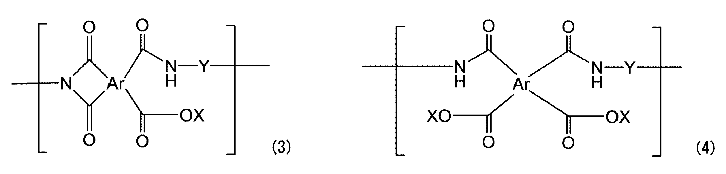
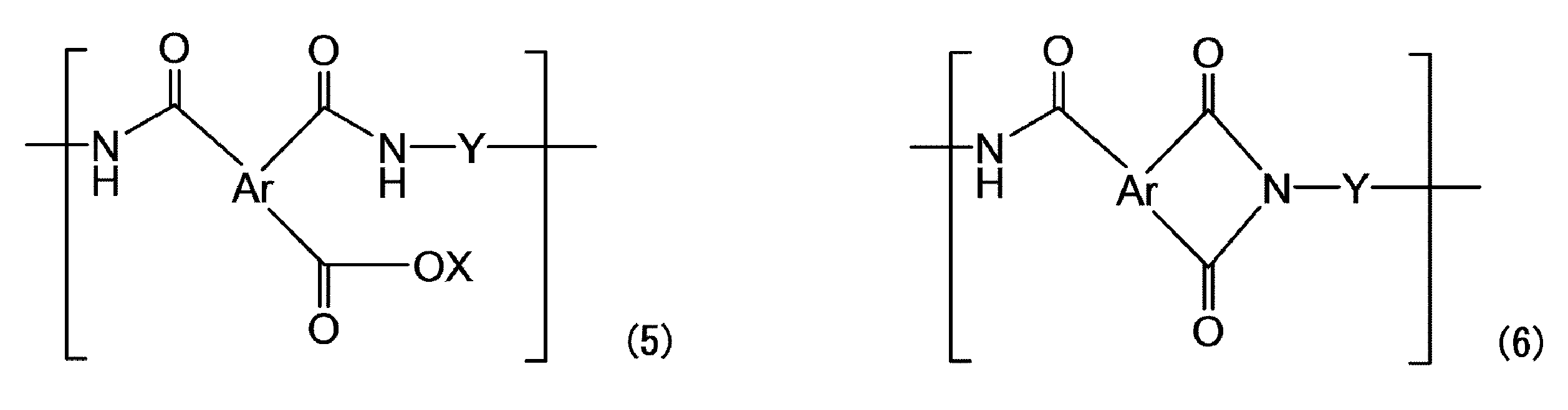
もっともポリアミドイミドの場合、一般のポリアミドイミドが有するイミド結合の開環によらずに元々有しているアミド結合(-NH-C(=O)-)を有することのみによっても本発明の目的を達成することができることを本発明者らは見出した。とはいえポリアミドイミドにおいても、ポリアミドイミドが本来有するイミド結合の一部が開環して上記(5)で表される構成単位を有することが好ましい。
(1)後述のイミド結合開環工程を行わないポリイミド及び/又はポリアミドイミド多孔質膜(ただし、当該多孔質膜を作成するためのワニスがポリアミド酸を含む場合、焼成工程において、実質的にイミド化反応が完結しているものとする。)について、フーリエ変換型赤外分光(FT-IR)装置により測定したイミド結合を表すピークの面積を、同じくFT-IR装置により測定したベンゼンを表すピークの面積で除した値で表される値(X1)を求める。
(2)前記値(X1)を求めた多孔質膜と同一のポリマー(ワニス)を用いて、得られたポリイミド及び/又はポリアミドイミド多孔質膜に対し、後述のイミド結合開環工程を行った後のポリイミド及び/又はポリアミドイミド多孔質膜について、フーリエ変換型赤外分光(FT-IR)装置により測定したイミド結合を表すピークの面積を、同じくFT-IR装置により測定したベンゼンを表すピークの面積で除した値で表される値(X2)を求める。
(3)不変化率(%)=(X2)÷(X1)×100
本発明におけるポリイミド及び/又はポリアミドイミド多孔質膜について、不変化率は、60%以上であることが好ましく、70%~99.5%であることがより好ましく、80~99%であることが更に好ましい。
ポリアミドイミドを含む多孔質膜の場合は、イミド結合の開環によらずに元々有しているアミド結合(-NH-C(=O)-)を構成する-NH-結合を含むため、不変化率は100%であってもよい。
本発明におけるポリイミド及び/又はポリアミドイミド多孔質膜は、ポリイミド及び/又はポリアミドイミドにおけるイミド結合の一部からカルボキシ基及び/又は塩型カルボキシ基を形成する工程(以下、「イミド結合開環工程」ということがある。)を含む方法により製造することができる。イミド結合開環工程において、上述のように、イミド結合の一部からカルボキシ基及び/又は塩型カルボキシ基を形成する場合、実質的に同時に、理論上これらの基と等モルの-NH-結合も形成される。イミド結合開環工程は、後述のケミカルエッチングにより行うことが好ましい。
ポリイミド及び/又はポリアミドイミド成形膜をイミド結合開環工程の前であるか後であるかに関わりなく多孔質化する方法としては、ポリイミド及び/又はポリアミドイミドと微粒子との複合膜(以下、「ポリイミド系樹脂-微粒子複合膜」ということがある。)から該微粒子を取り除いて多孔質化する微粒子除去工程を含む方法が好ましい。
ワニスの製造は、予め微粒子が分散した有機溶剤とポリアミド酸、ポリイミド又はポリアミドイミドを任意の比率で混合するか、微粒子を予め分散した有機溶剤中でテトラカルボン酸二無水物及びジアミンを重合してポリアミド酸とするか、更にイミド化してポリイミドとすることで製造でき、最終的に、その粘度を300~2000cP(0.3~2Pa・s)とすることが好ましく、400~1800cP(0.4~1.8Pa・s)の範囲がより好ましい。ワニスの粘度がこの範囲内であれば、均一に成膜をすることが可能である。
本発明で用いられる微粒子の材質は、ワニスに使用する有機溶剤に不溶で、成膜後選択的に除去可能なものなら、特に限定されることなく使用することができる。例えば、無機材料としては、シリカ(二酸化珪素)、酸化チタン、アルミナ(Al2O3)、炭酸カルシウム等の金属酸化物、有機材料としては、高分子量オレフィン(ポリプロピレン、ポリエチレン等)、ポリスチレン、アクリル系樹脂(メタクリル酸メチル、メタクリル酸イソブチル、ポリメチルメタクリレート(PMMA)等)、エポキシ樹脂、セルロース、ポリビニルアルコール、ポリビニルブチラール、ポリエステル、ポリエーテル、ポリエチレン等の有機高分子微粒子(樹脂微粒子)が挙げられる。
本発明に用いるポリアミド酸は、任意のテトラカルボン酸二無水物とジアミンを重合して得られるものが、特に限定されることなく使用できる。テトラカルボン酸二無水物及びジアミンの使用量は特に限定されないが、テトラカルボン酸二無水物1モルに対して、ジアミンを0.50~1.50モル用いるのが好ましく、0.60~1.30モル用いるのがより好ましく、0.70~1.20モル用いるのが特に好ましい。
本発明に用いるポリイミドは、本発明に係るワニスに使用する有機溶剤に溶解可能な可溶性ポリイミドなら、その構造や分子量に限定されることなく、公知のものが使用できる。ポリイミドについて、側鎖にカルボキシ基等の縮合可能な官能基又は焼成時に架橋反応等を促進させる官能基を有していてもよい。
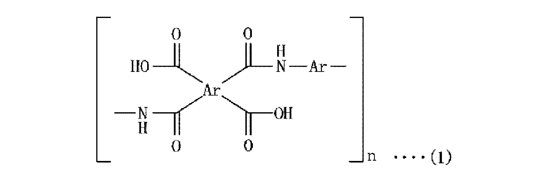

本発明に用いるポリアミドイミドは、本発明に係るワニスに使用する有機溶剤に溶解可能な可溶性ポリアミドイミドなら、その構造や分子量に限定されることなく、公知のものが使用できる。ポリアミドイミドについて、側鎖にカルボキシ基等の縮合可能な官能基又は焼成時に架橋反応等を促進させる官能基を有していてもよい。
ワニスに用いられる有機溶剤としては、ポリアミド酸及び/又はポリイミド系樹脂を溶解することができ、微粒子を溶解しないものであれば、特に限定されず、テトラカルボン酸二無水物とジアミンとの反応に用いる溶剤として例示したものが挙げられる。溶剤は、単独で用いてもよく、2種以上を組み合わせて用いてもよい。
ポリアミド酸又はポリイミド系樹脂と微粒子とを含有する未焼成複合膜の成形は、成膜の場合、基板上へ上記のワニスを塗布し、常圧又は真空下で0~120℃(好ましくは0~100℃)、より好ましくは常圧下60~95℃(更に好ましくは65~90℃)で乾燥して行う。塗布膜厚は、例えば、1~500μmであり、5~50μmが好ましい。なお、基板上には必要に応じて離型層を設けてもよい。また、未焼成複合膜の製造において、後述のポリイミド系樹脂-微粒子複合膜の製造(焼成工程)の前に、水を含む溶剤への浸漬工程、プレス工程、当該浸漬工程後の乾燥工程をそれぞれ任意の工程として設けてもよい。
上記乾燥後の未焼成複合膜(又は2層状の未焼成複合膜、以下同様)に加熱による後処理(焼成)を行ってポリイミド系樹脂と微粒子とからなる複合膜(ポリイミド系樹脂-微粒子複合膜)とすることができる。ワニスにポリアミド酸を含む場合、焼成工程においてはイミド化を完結させることが好ましい。なお、焼成工程は任意の工程である。特にワニスにポリイミド又はポリアミドイミドが用いられる場合、焼成工程は行われなくてもよい。
ポリイミド系樹脂-微粒子複合膜から、微粒子を適切な方法を選択して除去することにより、微細孔を有するポリイミド系樹脂多孔質膜を再現性よく製造することができる。例えば、微粒子として、シリカを採用した場合、ポリイミド系樹脂-微粒子複合膜を低濃度のフッ化水素水(HF)等によりシリカを溶解除去することで、多孔質とすることが可能である。また、微粒子が樹脂微粒子の場合は、上述のような樹脂微粒子の熱分解温度以上で、ポリイミド系樹脂の熱分解温度未満の温度に加熱し、樹脂微粒子を分解させてこれを取り除くことができる。
本発明におけるポリイミド系樹脂多孔質膜の製造方法は、上述のようにイミド結合開環工程を含むものであってよいが、具体的には、(a)微粒子除去工程の前に、ポリイミド系樹脂-微粒子複合膜にイミド結合開環工程を施すか、又は、(b)微粒子除去工程の後に、該工程により多孔質化したポリイミド系樹脂成形膜にイミド結合開環工程を施すことを含む方法により行うことができる。上記製造方法としては、前者の(a)の方法であっても、ポリイミド系樹脂成形膜の外表面及びその近傍に存在するイミド結合を開環することができ、本発明の目的を達成することができるが、得られるポリイミド系樹脂多孔質膜における多孔質の程度を高めることができる点で、後者の(b)の方が好ましい。
ケミカルエッチング後の洗浄としては、水洗単独でもよいが、酸洗浄及び/又は水洗を組み合わせることが好ましい。
また、ポリイミド系樹脂多孔質膜の表面の有機溶媒への濡れ性向上及び残存有機物除去のため、ポリイミド系樹脂多孔質膜の再度焼成工程を行ってもよい。焼成条件は、[ポリイミド系樹脂-微粒子複合膜の製造(焼成工程)]における焼成条件と同様、適宜設定すればよい。
本発明の液体の精製方法は、該液体の一部又は全部を、上述のポリイミド及び/又はポリアミドイミド多孔質膜の一方の側から他方の側へ差圧により透過させることを含む。
減圧は、ポリイミド系樹脂多孔質膜を透過した液体を集める側(濾液側)を減圧するものであり、例えば、ポンプによる減圧であってもよいが、真空にまで減圧することが好ましい。
ポンプによる供給液の循環若しくは送液を行う場合、通常、ポンプは、供給液漕(又は循環漕)とポリイミド系樹脂多孔質膜との間に配置される。
供給液を透過させる前の上記溶液とポリイミド系樹脂多孔質膜との接触においては、上記溶液にポリイミド系樹脂多孔質膜を含浸ないし浸漬させてもよく、ポリイミド系樹脂多孔質膜を溶液と接触させることによって、例えば、ポリイミド系樹脂多孔質膜の内部の孔にも溶液を浸透させることができる。供給液を透過させる前の上記溶液とポリイミド系樹脂多孔質膜との接触は、上述の差圧により行ってもよく、特に、ポリイミド系樹脂多孔質膜の内部の孔にも溶液を浸透させる場合、加圧下により行ってもよい。
本発明の第二の態様である、薬液又は洗浄液の製造方法は、本発明の第一の態様の液体の精製方法を用いる。本発明の第一の態様の液体の精製方法が上述のように精製効果に優れた方法であるので、かかる液体の精製方法を用いる、本発明の第二の態様の製造方法は、不純物の含有量が低減された薬液又は洗浄液を製造することができる。
・テトラカルボン酸二無水物:ピロメリット酸二無水物
・ジアミン:4,4’-ジアミノジフェニルエーテル
・ポリアミド酸溶液:ピロメリット酸二無水物と4,4’-ジアミノジフェニルエーテルとの反応物(固形分21.9質量%(有機溶剤:N,N-ジメチルアセトアミド))
・有機溶剤(1):N,N-ジメチルアセトアミド(DMAc)
・有機溶剤(2):ガンマブチロラクトン
・分散剤:ポリオキシエチレン二級アルキルエーテル系分散剤
・微粒子:シリカ(1):平均粒径700nmのシリカ
シリカ(2):平均粒径300nmのシリカ
・エッチング液(1):
メタノール:水(質量比3:7)の混合液のNaOH 1.1質量%溶液
・エッチング液(2):
メタノール:水(質量比4:6)の混合液の水酸化テトラメチルアンモニウム(TMAH) 1.0質量%溶液
[シリカ分散液の調製]
有機溶剤(1)23.1質量部及び分散剤0.1質量部の混合物に、表1に示す平均粒径を有するシリカ(1)又はシリカ(2)を23.1質量部添加し、撹拌してシリカ分散液を調製した。
ポリアミド酸溶液41.1質量部に、シリカ分散液の調製で得たシリカ分散液を42.0質量部添加し、更に有機溶剤(1)及び(2)をワニス全体における溶剤組成が有機溶剤(1):有機溶剤(2)=90:10となるようにそれぞれ追加し、撹拌してワニスを調製した。なお、得られたワニスにおけるポリアミド酸とシリカとの体積比は40:60(質量比は30:70)である。
上記のワニスを、基材としてポリエチレンテレフタレート(PET)フィルムにアプリケーターを用い成膜した。90℃で5分間プリベークして、膜厚40μmの未焼成複合膜を製造した。水に3分間浸漬したのち、2本のロール間に未焼成複合膜を通して、未焼成複合膜をプレスした。その際、ロール抑え圧は3.0kg/cm2、ロール温度は80℃、未焼成複合膜の移動速度は0.5m/minであった。基材から未焼成複合膜を剥離して未焼成複合膜を得た。
上記未焼成複合膜を表1に記載した温度で各15分間加熱処理(焼成)を施すことにより、イミド化させ、ポリイミド-微粒子複合膜を得た。
上記で得たポリイミド-微粒子複合膜を、10%HF溶液中に10分間浸漬することで、膜中に含まれる微粒子を除去した後水洗及び乾燥を行い、ポリイミド多孔質膜を得た。
実施例1及び2において、イミド結合開環工程として、ポリイミド多孔質膜をケミカルエッチング液(1)に2分間浸漬してイミド結合開環工程を施し、ポリイミド多孔質膜を得た。その後、表1に示す温度及び時間で再焼成を行った。
実施例3及び4においては、イミド結合開環工程としてのケミカルエッチング及びその後の再焼成を行わなかった。
比較例1としてポリアミド(ナイロン)製多孔質膜(孔サイズ:約10nm以下、膜厚約75μm)、比較例2としてポリエチレン製多孔質膜(孔サイズ:約10nm以下、膜厚約50μm)をそれぞれ用意した。
上記により用意した各多孔質膜について下記評価を行った。
イミド結合開環工程としてケミカルエッチング処理を行った多孔質膜については上述のように表1に示す温度で15分間再焼成したのち、フーリエ変換型赤外分光(FT-IR)装置により測定したイミド結合を表すピークの面積を、同じくFT-IR装置により測定したベンゼンを表すピークの面積で除した値(前述のX2)を求めた。各多孔質膜と同様のワニスにより作成した多孔質膜(実質的にイミド化反応が完結した、ケミカルエッチング処理を行わない膜)について測定した値(前述のX1)を求め、不変化率(%)を求めた。各不変化率とX2との値について、それぞれ表1に併記する。
用意した各多孔質膜を3cm×3mmの大きさに切り出して短冊状のサンプルを得た。このサンプルの破断時の応力(MPa;引張強度)及び破断伸度(%GL)を、EZ Test(島津製作所社製)を用いて評価した。結果を表1に表す。
用意した各多孔質膜を直径47mmの円形に切り取ってろ材として用い、ハウジングセットした後、200mLのイソプロピルアルコールを通液させた。その後、鉄及び亜鉛を純水(DIW)又はプロピレングリコールモノメチルエーテル(PGME)に添加して調製した金属不純物含有液を、該液の鉄、亜鉛の各含有量(A)を測定したのち、0.08MPaで窒素加圧しながら通液し、各金属不純物含有液の通液にかかった時間を測定し流速(ml/分)を求めた。結果を表1に表す。
通液後の液の鉄、亜鉛の各含有量(B)を測定し、下記式で表される値をメタル除去率(%)とし、以下の基準で評価した。結果を表1に表す。
(A-B)/B×100
但し、ポリエチレン製多孔質膜は、0.08MPaでは膜が破れてメタル除去率を計算できなかったので、0.04MPaで窒素加圧して通液した際のメタル除去率(%)を参考値として示す。
上記の各多孔質膜に対して、厚さ約40μmのサンプルを、5cm角に切り出した。ガーレー式デンソメーター(東洋精機社製)を用いて、JIS P 8117に準じて、100mlの空気が上記サンプルを通過する時間を測定した。結果を表1に表す。
実施例1~4と同じ各ポリイミド多孔質膜の試験片を用意し、酢酸ブチルとシクロヘキサノンに室温で24時間浸漬した後の影響を確認した。具体的に、浸漬前の引張強度を100%とした場合の浸漬後の引張強度の低下率を求めた。引張強度は、上述の破断時の応力の測定方法と同様にして測定した。引張強度の低下率はいずれの溶媒でも1%未満であり、溶剤による影響がほとんどないことが確認できた。

また、各実施例は、DIWでは比較例1と同等以上、PGMEでは比較例2よりも速い流速であり、水系と溶剤系の何れにも適用可能な流速範囲であることが確認できた。
各実施例は、比較例よりも薄い膜厚で高い除去率と適正な流速を有していることから、フィルターメディア又はフィルターデバイスにポリイミド系樹脂多孔質膜を使用する際、メディアの薄膜化やデバイスの小型化が可能であり、ポリイミド系樹脂多孔質膜をヒダ状に加工する場合も何重にもヒダ化できるため、より高い除去性能を有するフィルターデバイスを作成することが可能となる。
実施例1及び実施例2と実施例3及び実施例4とから、イミド結合開環工程としてのケミカルエッチングを行う方が、純水及びPGMEにおけるメタル除去率が向上することがわかった。
実施例1及び実施例3と、実施例2及び実施例4とから、イミド結合開環工程としてのケミカルエッチングによりイミド化率を下げると、メタル除去率(吸着率)を良好に維持したまま、流速の向上が可能になることがわかった。
ポリエチレン製多孔質膜を用いた比較例2では、上述の[流速]に関して記載したように0.08MPaの窒素加圧で膜が破れてしまったので、表1に示すPGMEにおけるFeのメタル除去率は、0.04MPaの窒素加圧下としたため、流速は2ml/分よりも更に遅くなり、かかる遅い流速ゆえに他の速い流速で行った各実施例よりも有利な条件となりFeの除去が進んだものと推察される。
以上のように従来のナイロン製多孔質膜を用いた比較例1及びポリエチレン製多孔質膜を用いた比較例2では、速い流速と高いメタル除去率との両立が不可能であることがわかった。
実施例2と同様のポリイミド多孔質膜を備えるフィルターデバイスを用意した。
ケミカルエッチング液としてエッチング液(2)を用いた他は、実施例2と同様にしてポリイミド多孔質膜を得た。得られたポリイミド多孔質膜の前述のX2のイミド化率は、1.51であった。ガーレー透気度は230秒であった。そのポリイミド多孔質膜を備えるフィルターデバイスを用意した。
ポリアミド(ナイロン)製多孔質膜(孔サイズ:約20nm)を備えるフィルターデバイス(Pall社製、Dispo)を用意した。
実施例5及び6並びに比較例3により用意した各フィルターデバイスについて、表2に示す通液対象を用いて、下記評価を行った。
[メタル除去率]
以下の樹脂溶液及び化学増幅型レジスト組成物を調製し、メタル除去率を評価した。メタル除去率は、上述のメタル除去率の評価と同様の式により求めた。通液前の樹脂溶液又は化学増幅型レジスト組成物の鉄含有量を(A)とし、用意した各フィルターデバイスによる通液後の液の鉄不純物量を(B)とした。ろ過条件は、いずれの場合も、室温で濾過圧1.0kgf/cm2(9.8N/cm2)とした。
下記高分子化合物(1)~(3)をそれぞれ、プロピレングリコールモノメチルエーテルアセテート:プロピレングリコールモノメチルエーテル=60:40(質量比)の混合溶剤に溶解した4質量%の樹脂溶液。
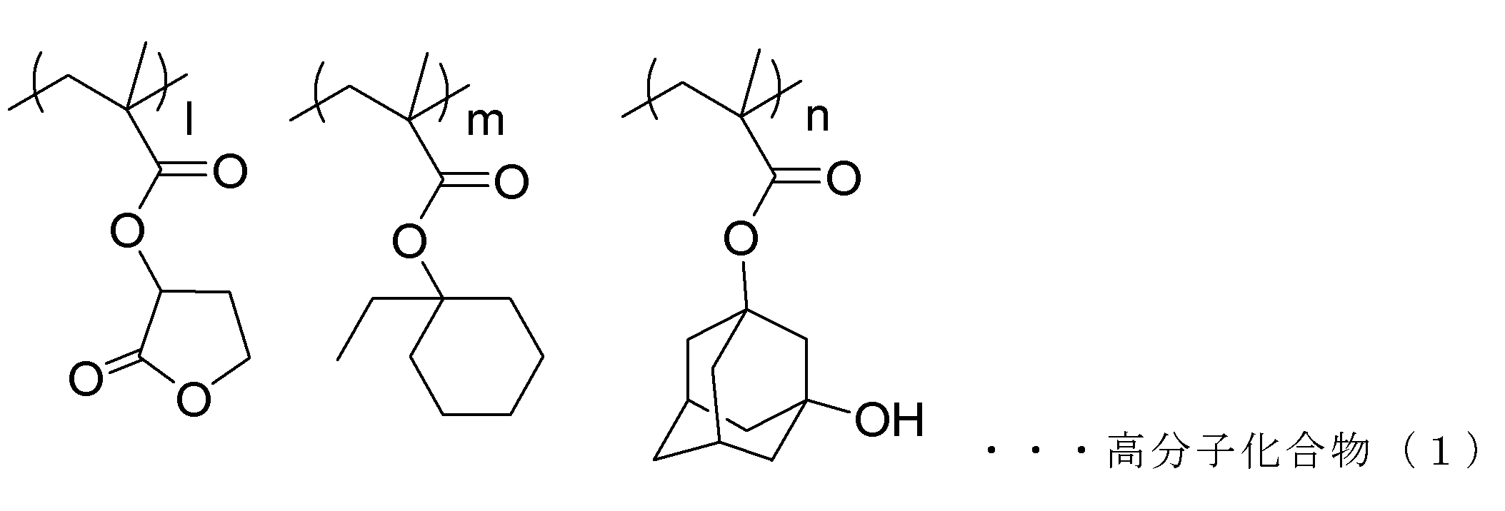


上記高分子化合物(1)100質量部と、下記酸発生剤(1)3.6質量部と、トリ-n-オクチルアミン0.4質量部とを、プロピレングリコールモノメチルエーテルアセテート:プロピレングリコールモノメチルエーテル=60:40(質量比)の混合溶剤と、混合し、高分子化合物(1)の固形分濃度が約7%になるように調製して化学増幅型レジスト組成物(以下、「レジスト(1)」ということがある。)を得た。


Claims (10)
- 液体の精製方法であって、
前記液体の一部又は全部を、連通孔を有するポリイミド及び/又はポリアミドイミド多孔質膜の一方の側から他方の側へ差圧により透過させることを含む、
液体の精製方法。 - 前記多孔質膜により、前記液体に含有される常温で固体の元素を含む不純物の一部又は全部が前記液体から除去される、請求項1記載の液体の精製方法。
- 前記差圧が、流液圧、真空、及び、不活性ガス若しくは非反応性ガスによる陽圧からなる群より選択される少なくとも1つを利用することにより加えられる、請求項1又は2に記載の液体の精製方法。
- 前記連通孔は、平均球径が50~2000nmである略球状孔が相互に連通した構造を含む、請求項1~3の何れか1項記載の液体の精製方法。
- 前記連通孔は、孔径が1~200nmである連通孔を含む、請求項1~4の何れか1項記載の液体の精製方法。
- 前記略球状孔は、内面に更に凹部を有している、請求項4記載の液体の精製方法。
- 前記液体は、半導体製造に用いられる薬液又は洗浄液である、請求項1~6の何れか1項記載の液体の精製方法。
- 請求項1~7の何れか1項記載の液体の精製方法を用いる、薬液又は洗浄液の製造方法。
- 請求項1~7の何れか1項記載の液体の精製方法に用いられる前記ポリイミド及び/又はポリアミドイミド多孔質膜からなるフィルターメディア。
- 請求項1~7の何れか1項記載の液体の精製方法に用いられる前記ポリイミド及び/又はポリアミドイミド多孔質膜を含む、フィルターデバイス。
Priority Applications (3)
| Application Number | Priority Date | Filing Date | Title |
|---|---|---|---|
| US15/549,740 US10576433B2 (en) | 2015-02-23 | 2016-02-22 | Method for purifying liquid, method for producing chemical solution or cleaning solution, filter medium, and filter device |
| KR1020177022061A KR102069428B1 (ko) | 2015-02-23 | 2016-02-22 | 액체의 정제 방법, 약액 또는 세정액의 제조 방법, 필터 미디어 및 필터 디바이스 |
| CN201680011538.XA CN107249720B (zh) | 2015-02-23 | 2016-02-22 | 液体的纯化方法、药液或清洗液的制造方法、过滤介质及过滤装置 |
Applications Claiming Priority (4)
| Application Number | Priority Date | Filing Date | Title |
|---|---|---|---|
| JP2015-033425 | 2015-02-23 | ||
| JP2015033425 | 2015-02-23 | ||
| JP2016-019176 | 2016-02-03 | ||
| JP2016019176A JP7084683B2 (ja) | 2015-02-23 | 2016-02-03 | 液体の精製方法、薬液又は洗浄液の製造方法、フィルターメディア、及び、フィルターデバイス |
Publications (1)
| Publication Number | Publication Date |
|---|---|
| WO2016136673A1 true WO2016136673A1 (ja) | 2016-09-01 |
Family
ID=56788480
Family Applications (1)
| Application Number | Title | Priority Date | Filing Date |
|---|---|---|---|
| PCT/JP2016/055079 Ceased WO2016136673A1 (ja) | 2015-02-23 | 2016-02-22 | 液体の精製方法、薬液又は洗浄液の製造方法、フィルターメディア、及び、フィルターデバイス |
Country Status (1)
| Country | Link |
|---|---|
| WO (1) | WO2016136673A1 (ja) |
Citations (5)
| Publication number | Priority date | Publication date | Assignee | Title |
|---|---|---|---|---|
| JPH0957069A (ja) * | 1995-08-30 | 1997-03-04 | Mitsubishi Chem Eng Corp | 浸透気化法による有機液体の精製方法及びそれに用いる装置並びにこれらを利用した蒸気乾燥 |
| US20070209506A1 (en) * | 2006-03-10 | 2007-09-13 | Chunqing Liu | Flexible Template-Directed Microporous Partially Pyrolyzed Polymeric Membranes |
| WO2013094528A1 (ja) * | 2011-12-20 | 2013-06-27 | オルガノ株式会社 | 液体管理システム、および洗浄液の回収再生装置 |
| JP2014094501A (ja) * | 2012-11-09 | 2014-05-22 | Daicel Corp | 多孔膜積層体及びその製造方法 |
| WO2014175011A1 (ja) * | 2013-04-22 | 2014-10-30 | 東京応化工業株式会社 | 多孔質ポリイミド膜の製造方法、多孔質ポリイミド膜、及びそれを用いたセパレータ |
-
2016
- 2016-02-22 WO PCT/JP2016/055079 patent/WO2016136673A1/ja not_active Ceased
Patent Citations (5)
| Publication number | Priority date | Publication date | Assignee | Title |
|---|---|---|---|---|
| JPH0957069A (ja) * | 1995-08-30 | 1997-03-04 | Mitsubishi Chem Eng Corp | 浸透気化法による有機液体の精製方法及びそれに用いる装置並びにこれらを利用した蒸気乾燥 |
| US20070209506A1 (en) * | 2006-03-10 | 2007-09-13 | Chunqing Liu | Flexible Template-Directed Microporous Partially Pyrolyzed Polymeric Membranes |
| WO2013094528A1 (ja) * | 2011-12-20 | 2013-06-27 | オルガノ株式会社 | 液体管理システム、および洗浄液の回収再生装置 |
| JP2014094501A (ja) * | 2012-11-09 | 2014-05-22 | Daicel Corp | 多孔膜積層体及びその製造方法 |
| WO2014175011A1 (ja) * | 2013-04-22 | 2014-10-30 | 東京応化工業株式会社 | 多孔質ポリイミド膜の製造方法、多孔質ポリイミド膜、及びそれを用いたセパレータ |
Similar Documents
| Publication | Publication Date | Title |
|---|---|---|
| JP6999764B2 (ja) | 液体の精製方法、薬液又は洗浄液の製造方法、フィルターメディア、及び、フィルターデバイス | |
| CN107207760B (zh) | 聚酰亚胺及/或聚酰胺酰亚胺多孔质体及其制造方法和用途 | |
| JP7489772B2 (ja) | 多孔質膜の製造方法、多孔質膜製造用の組成物の製造方法、及び多孔質膜 | |
| US20170321168A1 (en) | Polyimide-based resin film cleaning liquid, method for cleaning polyimide-based resin film, method for producing polyimide coating, method for producing filter, filter medium, or filter device, and method for producing chemical solution for lithography | |
| KR102447053B1 (ko) | 액체의 정제 방법, 및 다공질막의 제조 방법 | |
| JP7799390B2 (ja) | ポリイミド多孔質膜 | |
| CN117839447A (zh) | 多孔质膜 | |
| CN118440497A (zh) | 多孔质膜制造用组合物、多孔质膜的制造方法及多孔质膜 | |
| JP2025151135A (ja) | ろ過処理方法、及び多孔質膜 | |
| WO2016136673A1 (ja) | 液体の精製方法、薬液又は洗浄液の製造方法、フィルターメディア、及び、フィルターデバイス | |
| US20240084091A1 (en) | Porous film | |
| WO2026004486A1 (ja) | 多孔質膜、レジスト組成物の精製方法、及びレジスト膜の製造方法 | |
| CN121794049A (zh) | 多孔质膜、及多孔质膜的制造方法 |
Legal Events
| Date | Code | Title | Description |
|---|---|---|---|
| 121 | Ep: the epo has been informed by wipo that ep was designated in this application |
Ref document number: 16755419 Country of ref document: EP Kind code of ref document: A1 |
|
| ENP | Entry into the national phase |
Ref document number: 20177022061 Country of ref document: KR Kind code of ref document: A |
|
| WWE | Wipo information: entry into national phase |
Ref document number: 201680011538.X Country of ref document: CN |
|
| NENP | Non-entry into the national phase |
Ref country code: DE |
|
| 122 | Ep: pct application non-entry in european phase |
Ref document number: 16755419 Country of ref document: EP Kind code of ref document: A1 |
|
| WWG | Wipo information: grant in national office |
Ref document number: 201680011538.X Country of ref document: CN |