WO2016136656A1 - 機械的及び電気化学的キャビテーションを発生させる方法、物質の表面の幾何学的形状および電気化学的性質を変化させる方法、レアメタルを剥離する方法、機械的及び電気化学的キャビテーションの発生装置、及び、重水素の核融合反応を発生させる方法 - Google Patents
機械的及び電気化学的キャビテーションを発生させる方法、物質の表面の幾何学的形状および電気化学的性質を変化させる方法、レアメタルを剥離する方法、機械的及び電気化学的キャビテーションの発生装置、及び、重水素の核融合反応を発生させる方法 Download PDFInfo
- Publication number
- WO2016136656A1 WO2016136656A1 PCT/JP2016/055016 JP2016055016W WO2016136656A1 WO 2016136656 A1 WO2016136656 A1 WO 2016136656A1 JP 2016055016 W JP2016055016 W JP 2016055016W WO 2016136656 A1 WO2016136656 A1 WO 2016136656A1
- Authority
- WO
- WIPO (PCT)
- Prior art keywords
- cavitation
- electrochemical
- mechanical
- flow
- water
- Prior art date
- Legal status (The legal status is an assumption and is not a legal conclusion. Google has not performed a legal analysis and makes no representation as to the accuracy of the status listed.)
- Ceased
Links
Images






Classifications
-
- F—MECHANICAL ENGINEERING; LIGHTING; HEATING; WEAPONS; BLASTING
- F15—FLUID-PRESSURE ACTUATORS; HYDRAULICS OR PNEUMATICS IN GENERAL
- F15D—FLUID DYNAMICS, i.e. METHODS OR MEANS FOR INFLUENCING THE FLOW OF GASES OR LIQUIDS
- F15D1/00—Influencing flow of fluids
-
- B—PERFORMING OPERATIONS; TRANSPORTING
- B23—MACHINE TOOLS; METAL-WORKING NOT OTHERWISE PROVIDED FOR
- B23P—METAL-WORKING NOT OTHERWISE PROVIDED FOR; COMBINED OPERATIONS; UNIVERSAL MACHINE TOOLS
- B23P17/00—Metal-working operations, not covered by a single other subclass or another group in this subclass
-
- B—PERFORMING OPERATIONS; TRANSPORTING
- B23—MACHINE TOOLS; METAL-WORKING NOT OTHERWISE PROVIDED FOR
- B23P—METAL-WORKING NOT OTHERWISE PROVIDED FOR; COMBINED OPERATIONS; UNIVERSAL MACHINE TOOLS
- B23P17/00—Metal-working operations, not covered by a single other subclass or another group in this subclass
- B23P17/04—Metal-working operations, not covered by a single other subclass or another group in this subclass characterised by the nature of the material involved or the kind of product independently of its shape
-
- G—PHYSICS
- G21—NUCLEAR PHYSICS; NUCLEAR ENGINEERING
- G21B—FUSION REACTORS
- G21B3/00—Low temperature nuclear fusion reactors, e.g. alleged cold fusion reactors
-
- G—PHYSICS
- G21—NUCLEAR PHYSICS; NUCLEAR ENGINEERING
- G21B—FUSION REACTORS
- G21B3/00—Low temperature nuclear fusion reactors, e.g. alleged cold fusion reactors
- G21B3/008—Fusion by pressure waves
-
- B—PERFORMING OPERATIONS; TRANSPORTING
- B08—CLEANING
- B08B—CLEANING IN GENERAL; PREVENTION OF FOULING IN GENERAL
- B08B3/00—Cleaning by methods involving the use or presence of liquid or steam
- B08B3/04—Cleaning involving contact with liquid
- B08B3/10—Cleaning involving contact with liquid with additional treatment of the liquid or of the object being cleaned, e.g. by heat, by electricity or by vibration
- B08B3/102—Cleaning involving contact with liquid with additional treatment of the liquid or of the object being cleaned, e.g. by heat, by electricity or by vibration with means for agitating the liquid
-
- B—PERFORMING OPERATIONS; TRANSPORTING
- B08—CLEANING
- B08B—CLEANING IN GENERAL; PREVENTION OF FOULING IN GENERAL
- B08B3/00—Cleaning by methods involving the use or presence of liquid or steam
- B08B3/04—Cleaning involving contact with liquid
- B08B3/10—Cleaning involving contact with liquid with additional treatment of the liquid or of the object being cleaned, e.g. by heat, by electricity or by vibration
- B08B3/12—Cleaning involving contact with liquid with additional treatment of the liquid or of the object being cleaned, e.g. by heat, by electricity or by vibration by sonic or ultrasonic vibrations
-
- Y—GENERAL TAGGING OF NEW TECHNOLOGICAL DEVELOPMENTS; GENERAL TAGGING OF CROSS-SECTIONAL TECHNOLOGIES SPANNING OVER SEVERAL SECTIONS OF THE IPC; TECHNICAL SUBJECTS COVERED BY FORMER USPC CROSS-REFERENCE ART COLLECTIONS [XRACs] AND DIGESTS
- Y02—TECHNOLOGIES OR APPLICATIONS FOR MITIGATION OR ADAPTATION AGAINST CLIMATE CHANGE
- Y02E—REDUCTION OF GREENHOUSE GAS [GHG] EMISSIONS, RELATED TO ENERGY GENERATION, TRANSMISSION OR DISTRIBUTION
- Y02E30/00—Energy generation of nuclear origin
- Y02E30/10—Nuclear fusion reactors
-
- Y—GENERAL TAGGING OF NEW TECHNOLOGICAL DEVELOPMENTS; GENERAL TAGGING OF CROSS-SECTIONAL TECHNOLOGIES SPANNING OVER SEVERAL SECTIONS OF THE IPC; TECHNICAL SUBJECTS COVERED BY FORMER USPC CROSS-REFERENCE ART COLLECTIONS [XRACs] AND DIGESTS
- Y02—TECHNOLOGIES OR APPLICATIONS FOR MITIGATION OR ADAPTATION AGAINST CLIMATE CHANGE
- Y02E—REDUCTION OF GREENHOUSE GAS [GHG] EMISSIONS, RELATED TO ENERGY GENERATION, TRANSMISSION OR DISTRIBUTION
- Y02E60/00—Enabling technologies; Technologies with a potential or indirect contribution to GHG emissions mitigation
- Y02E60/30—Hydrogen technology
- Y02E60/36—Hydrogen production from non-carbon containing sources, e.g. by water electrolysis
Definitions
- the present invention relates to a method for generating mechanical and electrochemical cavitation, a method for changing the surface geometry and electrochemical properties of a material, a method for exfoliating a rare metal, and an apparatus for generating mechanical and electrochemical cavitation. And a method for generating a deuterium fusion reaction.
- Hydrogen can be converted into clean energy that does not emit carbon dioxide. Hydrogen reacts with oxygen to generate electricity, heat and water. Hydrogen is highly efficient in generating energy and has a wide range of uses, from automobiles to fuel for power generation facilities. Solar hydrogen production technology that produces hydrogen and oxygen by directly decomposing water with a photocatalyst or photoelectrode using an oxide semiconductor is low-cost, and research is actively promoted toward the realization of a future hydrogen society. Yes.
- Titanium oxide is low-cost and attracts attention as a material for photoelectrodes and photocatalysts for solar energy conversion materials.
- the TiO 2 photocatalytic reaction has a feature that light (ultraviolet light) having a wavelength of 350 nm is effective.
- sunlight contains only a small amount of ultraviolet rays, and in order to efficiently convert energy, it is essential to use visible light that accounts for half of the solar energy.
- Research to decorate titanium oxide to give visible light responsiveness has been actively conducted, and research to modify the metal surface has also been conducted (see Patent Document 1).
- the present invention relates to a method for generating mechanical and electrochemical cavitation, a method for changing the surface geometry and electrochemical properties of a material, and stripping rare metals using the generated mechanical and electrochemical cavitation. It is an object of the present invention to provide a method for generating a deuterium fusion reaction and a method for generating a mechanical and electrochemical cavitation and a deuterium fusion reaction.
- the flow cavitation is capable of inflating the flow cavitation with respect to the flow cavitation caused by the injection of the water jet, while jetting a water jet from an injection nozzle immersed in water.
- a method of generating mechanical and electrochemical cavitation that is distributed at positions spaced from the nozzle.
- the invention described in claim 2 is characterized in that, in claim 1, the moving speed of the flow cavitation is 5 m / s or less.
- the invention described in claim 3 is characterized in that, in claim 1, the frequency of the ultrasonic wave is 20 kHz or more and 33 kHz or less.
- a fourth aspect of the present invention is the method according to the first or second aspect, wherein the distance from the ultrasonic irradiation element that irradiates the ultrasonic wave to the water jet is 5 wavelengths or less of the ultrasonic wave. To do.
- the secondary generated around the collision object by causing the water jet injected from the injection nozzle to collide with the collision object.
- the high temperature reaction field of the flow cavitation including the high temperature reaction field is generated around the collision object by irradiating the ultrasonic wave to the flow cavitation of the jet.
- the invention according to claim 6 is a method in which mechanical and electrochemical cavitation generated by the method for generating mechanical and electrochemical cavitation according to any one of claims 1 to 5 is caused to collide with a substance, A method of changing the surface geometry and electrochemical properties of a material.
- the invention according to claim 7 is the invention according to claim 6, wherein the substance is composed of at least one selected from titanium oxide, platinum, and nickel oxide having a rutile-type or anatase-type crystal structure,
- the titanium oxide particles have a particle size of 100 nm to 400 nm, and the platinum or nickel oxide particles have a particle size of 0.1 ⁇ m to 85 ⁇ m.
- the invention described in claim 8 is characterized in that, in claim 6, an inert surface with less gas adsorption and high oxidation resistance and corrosion resistance is generated on the surface of the substance.
- the invention according to claim 9 is a coating in which the rare metal is deposited on the mechanical and electrochemical cavitation generated by the method for generating mechanical and electrochemical cavitation according to any one of claims 1 to 5.
- the rare metal is peeled off from the surface of the coating by colliding with the surface of the object.
- the invention according to claim 10 is characterized in that a flow velocity of the flow cavitation that allows the flow cavitation to expand relative to an injection nozzle that is immersed in water and jets a water jet, and the flow cavitation that occurs as the water jet is jetted.
- the high-temperature reaction field of the flow cavitation including the high-temperature reaction field, which is generated by irradiating ultrasonic waves to a position that is lower than a predetermined moving speed and repeating expansion and contraction by the ultrasonic waves, is emitted from the injection nozzle.
- An apparatus for generating mechanical and electrochemical cavitation, comprising ultrasonic irradiation elements distributed at spaced positions.
- fluid cavitation is generated by ejecting a liquid containing heavy water or deuterium from a spray nozzle immersed in a liquid containing heavy water or deuterium and ejecting the liquid containing heavy water or deuterium.
- the flow cavitation can be expanded, the ultrasonic wave is irradiated to a position where the flow velocity of the flow cavitation is equal to or lower than a predetermined movement speed, and the expansion and contraction are repeated by the irradiation of the ultrasonic wave.
- the high temperature reaction field of the flow cavitation including the reaction field is distributed at a position away from the injection nozzle, and deuterium fusion reaction is generated by the collapse of the cavitation.
- a method for generating mechanical and electrochemical cavitation a method for changing the surface geometry and electrochemical properties of a material, and the generated mechanical and electrochemical cavitation are utilized.
- a method for peeling a rare metal can be provided.
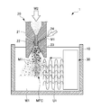
- FIG. 1 is a schematic diagram illustrating a method for generating mechanical and electrochemical cavitation MFC of Embodiment 1 according to the present invention.
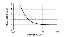
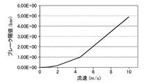
- FIG. It is a graph which shows the relationship between the break threshold value and the equilibrium radius in the method to generate the mechanical and electrochemical cavitation MFC of Embodiment 1 according to the present invention. It is a graph which shows the relationship between the break threshold value and the flow rate in the method of generating the mechanical and electrochemical cavitation MFC of Embodiment 1 according to the present invention. It is a graph which shows the relationship between the resonant frequency and the bubble radius in the method to generate
- FE-SEM Field Emission Scanning Electron Microscope showing the surface of titanium oxide made porous and held so as to enclose platinum by mechanical and electrochemical cavitation according to Embodiment 1 of the present invention
- Photo Field Emission Scanning Electron Microscope (FE-) showing the surface of titanium oxide made porous and held so as to enclose platinum by the mechanical and electrochemical cavitation MFC of Embodiment 1 according to the present invention.
- SEM Field Emission Scanning Electron Microscope
- FE- showing the surface of titanium oxide made porous and held so as to enclose platinum by the mechanical and electrochemical cavitation MFC of Embodiment 1 according to the present invention. SEM).
- FE- Field Emission Scanning Electron Microscope showing the surface of titanium oxide made porous and held so as to enclose platinum by the mechanical and electrochemical cavitation MFC of Embodiment 1 according to the present invention.
- SEM Field Emission Scanning Electron Microscope showing the surface of titanium oxide made porous and held so as to enclose platinum by the mechanical and electrochemical cavitation MFC of Embodiment 1 according to the present invention.
- SEM It is a field emission scanning electron microscope (FE-SEM) photograph showing the surface of titanium oxide in which platinum is attached by flow cavitation.
- FIG. 6 is a schematic diagram illustrating a method for generating mechanical and electrochemical cavitation MFC of Embodiment 2 according to the present invention. It is an electron micrograph which shows a mode that the ITO film
- a field emission scanning electron microscope (FE) showing a test result when the flow velocity of flow cavitation is 21 m / s. -SEM) Photo.
- a field emission scanning electron microscope (FE) showing a test result when the flow velocity of flow cavitation is 80 m / s. -SEM) Photo.
- FE field emission scanning electron microscope
- FIG. 1 is a schematic diagram illustrating a method for generating mechanical and electrochemical cavitation MFC according to Embodiment 1 of the present invention.
- a mechanical and electrochemical cavitation generator 1 for carrying out a method for generating mechanical and electrochemical cavitation includes a reactor 10, an injection nozzle 20, and an ultrasonic irradiation element 30. And have.
- the reactor 10 stores tap water W1.
- the injection nozzle 20 is connected to a high pressure water supply source (not shown).
- the discharge port of the injection nozzle 20 is immersed in tap water W1 stored in the reactor 10.
- High-pressure water W2 supplied from a high-pressure water supply source (not shown) is injected as a high-pressure water jet from the discharge port to tap water W1 stored in the reactor 10.
- the pressure of the high-pressure water W2 is 1 MPa or more and 70 MPa or less.
- the pressure of the high-pressure water W2 is less than 1 MPa, a moderately high-pressure water jet cannot be obtained, and nuclei of mechanical and electrochemical cavitation (hereinafter referred to as “functional cavitation MFC”) are generated. This is because functional cavitation MFC cannot be obtained appropriately. Further, when the pressure of the high-pressure water W2 exceeds 70 MPa, the pressure of the water jet is too high, and the core of the functional cavitation MFC is difficult to expand, so that the functional cavitation MFC cannot be obtained appropriately. In particular, when the pressure is 3 MPa or more, it is possible to inject a water jet for easily generating functional cavitation MFC.
- “mechanical and electrochemical cavitation (functional cavitation MFC)” is a machine that changes the geometric shape of the surface of the material, such as making the surface of the material such as titanium oxide porous. This means cavitation that can exert an electrochemical surface modification effect, such as reducing the band gap when water is decomposed into hydrogen and oxygen, as well as having a surface modification effect. .
- the injection nozzle 20 has an orifice portion 21, a mixing chamber 22, and a horn portion 23.
- the orifice portion 21 has a cylindrical shape.
- the upstream end of the orifice portion 21 communicates with a high-pressure water supply source (not shown).
- High pressure water W2 supplied from a high pressure water supply source (not shown) flows into the orifice portion 21.
- the upstream end portion of the mixing chamber 22 is connected to the downstream end portion of the orifice portion 21.
- the mixing chamber 22 is slightly larger in diameter than the orifice portion 21, and a substance inflow channel 24 having an inner diameter of about 1 mm to 4 mm communicates with the mixing chamber 22.
- High-pressure water W2 flows into the mixing chamber 22 from the orifice portion 21 and, by a side flow through the substance inflow channel 24, titanium oxide powder (TiO 2 ), platinum (Pt), nickel oxide (II) ( NiO) powder M1 flows in.
- Titanium oxide that flows in by a side flow through the substance inflow channel 24 has a rutile-type or anatase-type crystal structure.
- the titanium oxide particles have a particle size of 10 ⁇ m or less, preferably 100 nm or more and 400 nm or less. When the particle diameter exceeds 10 ⁇ m, the particle diameter is too large, and it becomes difficult to perform surface modification to make the surface of the titanium oxide particles finer to have a porous structure.
- the particle size of titanium oxide is preferably small, and in order to perform surface modification more efficiently, the particle size is preferably 400 nm or less.
- the particle size of the titanium oxide particles is less than 100 nm, the particles are too small to make it difficult to perform surface modification efficiently.
- platinum and nickel (II) oxide particles have a particle size of 0.1 ⁇ m or more and 85 ⁇ m or less.
- the particles of platinum and nickel oxide (II) it is preferable that the particle diameter is small in order to perform surface modification efficiently, as in the case of titanium oxide.
- the particle size of platinum and nickel (II) oxide exceeds 85 ⁇ m, it is difficult to efficiently perform surface modification of platinum and nickel (II) oxide.
- the particle diameters of platinum and nickel oxide (II) are less than 0.1 ⁇ m, the particles are too small, and it is difficult to efficiently carry out the surface modification by refining the surface to have a porous structure.
- the upstream end of the horn 23 is connected to the downstream end of the mixing chamber 22.
- the horn portion 23 increases in diameter in a tapered shape toward the tip of the horn portion 23 (the discharge port of the injection nozzle 20 constituted by the end portion on the downstream side of the horn portion 23). Therefore, the injection nozzle 20 is constituted by a horn nozzle.
- the maximum diameter of the tip of the horn part 23 is about 0.8 mm to 2 mm.
- the injection nozzle 20 having the above-described configuration injects a water jet in the tap water W1 stored in the reactor 10, and accordingly generates a flow cavitation in the tap water W1.
- the ultrasonic irradiation element 30 is electrically connected to a drive control device (not shown), and irradiates the water jet from the horizontal direction with respect to the water jet sprayed vertically downward. To do.
- the ultrasonic irradiation element 30 irradiates the ultrasonic wave U1 in the tap water W1 stored in the reactor 10 by the output from the drive control device.
- the frequency of the irradiated ultrasonic wave U1 is 20 kHz or more and 33 kHz or less.
- the frequency of the ultrasonic wave U1 to be irradiated is less than 20 kHz, the frequency is too low to obtain the effect of the ultrasonic wave U1.
- the frequency of the irradiated ultrasonic wave U1 exceeds 100 kHz, the frequency is too high to obtain the effect of the ultrasonic wave U1.
- the frequency exceeds 33 kHz the bubble radius is easily resonated and adiabatically compressed. This is because the bubble radius is separated and the bubble radius becomes difficult to be subjected to isothermal expansion and adiabatic compression. More preferably, it is around 28 kHz. The relationship between the bubble radius and the frequency of the ultrasonic wave U1 will be described later.
- the ultrasonic output rating value of the irradiated ultrasonic wave U1 is 100 W or more and 300 W or less. This is because if the ultrasonic output rated value of the irradiated ultrasonic wave U1 is less than 100 W, the output of the ultrasonic wave U1 is too weak to sufficiently perform crushing due to expansion / contraction of the core of cavitation. When the ultrasonic output rated value of the irradiated ultrasonic wave U1 exceeds 300 W, effective cavitation core expansion and crushing due to contraction cannot be performed, although the output of the ultrasonic wave U1 is strong. This is because there is no point in increasing the output.
- the resonance radius the radius that gives the resonance frequency of bubble vibration (vibration to the core of cavitation) is called the resonance radius, but if the sound pressure (ultrasonic output) is large, the core of cavitation does not expand much above the resonance radius. , Does not cause Rayleigh shrinkage (adiabatic compression).
- the sound pressure is equal to or less than the bubble radius (the sound pressure required for isothermal expansion)
- the expansion of the bubbles is small. This is because the equilibrium radius of an active bubble that generally causes Rayleigh contraction is between the Blake threshold and the resonance radius.
- the ultrasonic irradiation element 30 is a distance equal to or less than the distance corresponding to five wavelengths of the ultrasonic wave U1 irradiated from the ultrasonic irradiation element 30 from the water jet sprayed by the spray nozzle 20. It is arranged at a distant position. Specifically, when the frequency of the irradiated ultrasonic wave U1 is 28 kHz, the ultrasonic wave U1 is disposed at a position separated by about 54 mm or less from the water jet ejected by the ejection nozzle 20.
- the intensity of the ultrasonic wave U1 is reduced, and the core of the functional cavitation MFC does not move from the expanded state to the contracted state.
- the effect of surface modification of the substance by the functional cavitation MFC cannot be sufficiently obtained.
- the ultrasonic irradiation element 30 is ultrasonically applied to the flow cavitation at a position away from the injection nozzle 20 and in a position where the flow cavitation can expand and the flow velocity of the flow cavitation becomes a predetermined moving speed or less. Irradiate U1. Thereby, the high-temperature reaction field of the flow cavitation including the high-temperature reaction field is distributed at positions separated from the injection nozzle 20.
- the predetermined moving speed is 5 m / s.
- the predetermined moving speed is obtained as follows.
- the water vapor pressure is p v
- the atmospheric pressure is p o
- the surface tension is ⁇
- the equilibrium radius is R 0
- the minimum pressure required for the cavitation nucleus to expand is obtained by the following equation: .
- the conditions for the bubbles to overcome the surface tension ⁇ and expand greatly are as follows.
- FIG. 2 is a graph showing the relationship between the break threshold and the equilibrium radius in the method for generating mechanical and electrochemical cavitation MFC of Embodiment 1 according to the present invention. From the graph shown in FIG. 2, when the equilibrium radius is larger than 1 ⁇ m, the break threshold is equal to 1 bar (atmospheric pressure) and can be easily expanded.
- the liquid density is ⁇
- the liquid flow velocity is ⁇
- the vibration speed is ⁇ 0
- Bernoulli's theorem Bernoulli's theorem
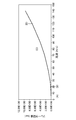
- FIG. 3 is a graph showing the relationship between the break threshold and the flow rate in the method for generating mechanical and electrochemical cavitation MFC of Embodiment 1 according to the present invention. From the graph shown in FIG. 3, when the flow velocity ⁇ is 4.52m / s, in a position spaced from the nozzle, the break threshold A Blake is equal to 1 bar.
- the break threshold A Blake suddenly increases from the position where the flow velocity of the flow cavitation exceeds a predetermined moving speed of 5 m / s, and the flow velocity of the flow cavitation increases as it approaches the injection nozzle 20. becomes enough, break threshold a Blake increases, in order to inflate the cavitation nuclei, it can be seen that a large sound pressure is required.
- FIG. 4 is a graph showing the relationship between the resonance frequency and the bubble radius in the method for generating the mechanical and electrochemical cavitation MFC according to the first embodiment of the present invention.
- the resonance frequency is 33 kHz or less.
- a method for generating mechanical and electrochemical cavitation using the apparatus 1 having the above configuration is performed as follows.
- the injection nozzle 20 injects the water jet by injecting the high-pressure water W2 into the tap water W1 while being immersed in the tap water W1 stored in the reactor 10. Thereby, a circulating vortex is generated in the water jet. Nuclei (cavitation nuclei) are generated in the circulating vortex. Flow cavitation occurs when the core pressure reaches the saturated vapor pressure at the water jet temperature.
- the ultrasonic irradiation element 30 irradiates the ultrasonic wave U1 with respect to the flow cavitation caused by the jet of the water jet.
- high and low pressures repeatedly occur in flow cavitation.
- the generation of nuclei, the diffusion and expansion of nuclei, the crushing of nuclei, and the generation of nuclei are repeated.
- the diffusion and expansion of nuclei and the generation of nuclei coincide with each other, so that flow cavitation including a high temperature reaction field (hot spot), that is, functional action and electrochemical action. Cavitation with both (mechanical and electrochemical cavitation MFC) occurs.
- the high-temperature reaction field of the flow cavitation including the high-temperature reaction field generated by expanding and contracting the flow cavitation by the ultrasonic wave U1 is as described above.
- the ultrasonic wave U1 since the ultrasonic wave U1 is irradiated, it is distributed ahead of the jet nozzle 20 in the jet direction of the water jet.
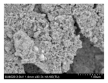
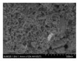
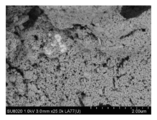
- FIG. 5 is a field emission scanning electron microscope showing the surface of titanium oxide made porous and held so as to enclose platinum by mechanical and electrochemical cavitation according to Embodiment 1 of the present invention.
- FE-SEM field emission scanning electron microscope
- FIG. 6 is a field emission type scanning electron showing a surface of titanium oxide that is made porous and held so as to enclose platinum by the mechanical and electrochemical cavitation MFC of Embodiment 1 according to the present invention. It is a microscope (FE-SEM) photograph.
- FIG. 5 is a field emission scanning electron microscope showing the surface of titanium oxide made porous and held so as to enclose platinum by mechanical and electrochemical cavitation according to Embodiment 1 of the present invention.
- FE-SEM field emission type scanning electron showing a surface of titanium oxide that is made porous and held so as to enclose platinum by the mechanical and electrochemical cavitation MFC of Embodiment 1 according to the present invention. It is a microscope (FE-SEM) photograph.
- FIG. 7 is a field emission scanning electron showing a surface of titanium oxide made porous and held so as to enclose platinum by the mechanical and electrochemical cavitation MFC of Embodiment 1 according to the present invention. It is a microscope (FE-SEM) photograph.
- FIG. 8 shows field emission scanning electrons showing the surface of titanium oxide made porous and held so as to enclose platinum by the mechanical and electrochemical cavitation MFC of Embodiment 1 according to the present invention. It is a microscope (FE-SEM) photograph.
- FIG. 9 is a field emission scanning electron showing a surface of titanium oxide made porous and held so as to enclose platinum by the mechanical and electrochemical cavitation MFC of Embodiment 1 according to the present invention. It is a microscope (FE-SEM) photograph.
- Conditions for generating the functional cavitation MFC are as follows. (Conditions for functional cavitation MFC) Pressure of high-pressure water supplied from the high-pressure water supply source to the injection nozzle 20: 35 MPa Ultrasound U1 irradiation and water jet spraying time: 2 minutes Ultrasound U1 frequency: 28 kHz Ultrasonic output rating: 225W Distance from water jet to ultrasonic irradiation element 30: 54 mm
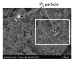
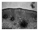
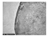
- the surface of titanium oxide subjected to mechanical and electrochemical surface modification is porous, and a large number of nm (nanometer) deep pores are formed. It can be seen that it is formed.
- platinum particles white portions
- titanium oxide in a state of being encased in titanium oxide (dark gray portions). 6 to 9 show that the same state occurs.
- FIG. 10 is a field emission scanning electron microscope (FE-SEM) photograph showing the surface of titanium oxide in which platinum is attached by flow cavitation.
- FE-SEM field emission scanning electron microscope
- the surface-modified titanium oxide powder or the like (the present invention product 1 to the present invention product 4, the comparison product 1 to the comparison product 4, the conventional product) is immersed in tap water.
- the Q mass apparatus quadrature mass spectrometer (QMS) apparatus
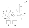
- FIG. 11 shows a Q mass apparatus (quadrupole mass spectrometer (QMS) apparatus) 100 for titanium oxide powder and the like surface-treated by the method for generating mechanical and electrochemical cavitation MFC according to Embodiment 1 of the present invention. It is the schematic which shows a mode that the effect is tested using.
- These powders were each irradiated for 1 hour with visible light L1 or ultraviolet light L1, and the amounts of hydrogen and oxygen generated were measured.
- the Q mass apparatus 100 includes a main vacuum chamber 111, a quadrupole mass spectrometer 121, an ionization vacuum gauge 122, valves 123 and 124, a turbo molecular pump 125, and a rotary pump 126.
- a quartz glass 112 disposed in the main vacuum chamber 111 titanium oxide powder or the like immersed in tap water (present product 1 to present product 4, comparative product 1 to comparative product 4, conventional product) is disposed. .
- the quadrupole mass spectrometer 121 and the ionization vacuum gauge 122 communicate with the main vacuum chamber 111, and a valve 123 is provided between the quadrupole mass spectrometer 121, the ionization vacuum gauge 122, and the main vacuum chamber 111. It is connected. Further, a turbo molecular pump 125 and a rotary pump 126 are communicated with the quadrupole mass spectrometer 121, the ionization vacuum gauge 122, and the main vacuum chamber 111 in this order via a valve 124.
- a predetermined amount of helium or argon is previously injected into the main vacuum chamber 111 as an internal standard substance. Then, the valves 123 and 124 are opened in appropriate amounts, and a certain amount of exhaust is performed by the turbo molecular pump 125. Then, the surface-modified titanium oxide powder or the like (the invention product 1 to the invention product 4, the comparison product 1 to the comparison product 4, the conventional product) is irradiated with visible light or ultraviolet light for 1 hour. During this time, the current values of hydrogen and oxygen ionized in the main vacuum chamber 111 were measured by the quadrupole mass spectrometer 121.
- the present invention product 1 to the present invention product 4 the comparison product 1 to the comparison product 4, and the conventional product used for the production of hydrogen and oxygen by the decomposition of water are as follows.
- the product 1 of the present invention is a powder of titanium oxide (TiO 2 ) having a rutile crystal structure of 90.9 wt% by a side flow through the substance inflow channel 24 using the apparatus of the first embodiment. And 9.1 wt% platinum powder was introduced into a water jet and surface modification of these materials was performed. The surface modification was performed by the method for generating mechanical and electrochemical cavitation in the first embodiment.
- the product 2 of the present invention is a powder of titanium oxide (TiO 2 ) having a rutile type crystal structure of 100 wt% by a side flow through the substance inflow channel 24 using the apparatus of the first embodiment.
- TiO 2 titanium oxide
- the surface modification was performed by the method for generating mechanical and electrochemical cavitation in the first embodiment.
- the product 3 of the present invention is a titanium oxide (TiO 2 ) having a rutile type crystal structure of 90.9 wt% by a side flow through the substance inflow channel 24 using the apparatus of the first embodiment.
- 9.1 wt% nickel (II) oxide (NiO) powder were introduced into a water jet and surface modification of these materials was performed. The surface modification was performed by the method for generating mechanical and electrochemical cavitation in the first embodiment.
- the product 4 of the present invention is a titanium oxide (TiO 2 ) having a 90.9 wt% anatase type crystal structure by the side flow through the substance inflow channel 24 using the apparatus of the first embodiment.
- 9.1 wt% platinum powder were introduced into a water jet and surface modification of these materials was performed. The surface modification was performed by the method for generating mechanical and electrochemical cavitation in the first embodiment.
- the comparative product 1 was obtained by using the apparatus of the first embodiment described above to obtain 90.9 wt% of a titanium oxide (TiO 2 ) powder having a rutile crystal structure and 9.1 wt% of a platinum powder. These materials were obtained by performing surface modification of these substances by flowing into the tap water W1 and irradiating them with ultrasonic waves U1 for 2 minutes and then exposing them to flow cavitation by a water jet for 2 minutes. .
- TiO 2 titanium oxide
- the comparative product 2 is made of titanium oxide (TiO 2 ) having a 90.9% by weight rutile crystal structure by the side flow through the substance inflow channel 24 using the apparatus of the first embodiment.
- TiO 2 titanium oxide
- These powders and 9.1 wt% platinum powder were introduced into a water jet and surface modification of these materials was performed.
- the titanium oxide powder and the platinum powder are caused to flow into the water jet by the side flow through the substance inflow channel 24 using the apparatus of the first embodiment, and flow cavitation by the water jet is performed.
- the ultrasonic wave U1 used in the mechanical and electrochemical cavitation in the first embodiment was performed by irradiating the titanium oxide powder and the platinum powder for 2 minutes.
- the comparative product 3 is made of titanium oxide (TiO 2 ) having a 90.9 wt% rutile crystal structure by the side flow through the material inflow channel 24 using the apparatus of the first embodiment. These powders and 9.1 wt% platinum powder were introduced into a water jet and surface modification of these materials was performed. In the surface modification, the titanium oxide powder and the platinum powder are caused to flow into the water jet by the side flow through the substance inflow channel 24 using the apparatus of Embodiment 1, and only flow cavitation by the water jet is performed. For 2 minutes.
- Comparative Product 4 using the apparatus of the above-described first embodiment, a powder and 9.1% by weight of platinum powders of titanium oxide (TiO 2) having a rutile crystal structure of 90.9 wt% It mixed with the tap water W1, and performed by irradiating the ultrasonic wave U1. The surface modification was performed by irradiating the titanium oxide powder and the platinum powder for 2 minutes only with the ultrasonic wave U1 used in the mechanical and electrochemical cavitation in the first embodiment.
- TiO 2 titanium oxide having a rutile crystal structure of 90.9 wt% It mixed with the tap water W1
- the surface modification was performed by irradiating the titanium oxide powder and the platinum powder for 2 minutes only with the ultrasonic wave U1 used in the mechanical and electrochemical cavitation in the first embodiment.
- present invention product 1 to present invention product 4 comparison product 1 to comparison product 4, and conventional product all have a mass of 1.0 g.
- the results are as shown in Table 1 for visible light irradiation and as shown in Table 2 for ultraviolet irradiation.
- the present invention product 1 and the present invention product 4 have titanium oxide having a rutile type crystal structure than the present product 4 having titanium oxide having an anatase type crystal structure. It can be seen that the product 1 of the present invention can obtain more hydrogen and oxygen by water decomposition.
- the present invention product 1 composed of 90.9% by weight of titanium oxide (TiO 2 ) powder having a rutile crystal structure and 9.1% by weight of platinum powder
- the product 1 of the present invention in which the surface modification is performed by the functional cavitation MFC is different from the comparison products 1 to 4 in which the surface modification by the functional cavitation MFC is not performed. It can be seen that hydrogen and oxygen can be obtained by decomposition of water more than 3 times.
- the amount of hydrogen and oxygen obtained by the decomposition of water obtained by irradiation with ultraviolet rays is small.
- the amount of hydrogen and oxygen resulting from the decomposition of water obtained by irradiation with ultraviolet light is much larger than that of the conventional product.
- the product 1 of the present invention can obtain 25 times more hydrogen than the conventional product.
- the present invention product 1 composed of 90.9 wt% titanium oxide (TiO 2 ) powder having a rutile crystal structure and 9.1 wt% platinum powder, comparison In the products 1 to 4, the product 1 of the present invention in which the surface modification is performed by the functional cavitation MFC is different from the comparison products 1 to 4 in which the surface modification by the functional cavitation MFC is not performed. It can be seen that hydrogen and oxygen can be obtained by decomposition of water more than 3 times.
- a water jet is jetted from the jet nozzle 20 immersed in water, and the flow cavitation is different from the flow cavitation caused by the jet of the water jet.
- a flow cavitation including a high-temperature reaction field is generated by irradiating an ultrasonic wave U1 to a position where the flow velocity of the flow cavitation is lower than a predetermined moving speed, and repeating expansion and contraction by the irradiation of the ultrasonic wave U1.
- the high temperature reaction field is distributed at a position away from the injection nozzle 20.
- a high-speed jet that pierces the solid surface of a substance such as titanium oxide when the core contracts and collapses after diffusion and expansion of the core of flow cavitation due to the irradiation of the ultrasonic wave U1.
- the surface modification of a substance such as titanium oxide can be promoted.
- the surface of titanium oxide can be made porous, and platinum can be oxidized in a state where platinum particles are encased in titanium oxide on the surface of the porous titanium oxide. It can be set as the state currently carried by titanium.
- a photocatalyst capable of effectively decomposing water into hydrogen and oxygen can be obtained not only by ultraviolet rays but also by visible light.
- the moving speed of fluid cavitation is 5 m / s or less.
- the frequency of the ultrasonic wave U1 is 20 kHz or more and 33 kHz or less. With this configuration, it is possible to irradiate the flow cavitation with the ultrasonic wave U1 having the same frequency as the resonance frequency of bubbles of 100 ⁇ m or more, which is the size of water jet cavitation. As a result, the cavitation nucleus can be easily expanded. Thereby, the method of generating mechanical and electrochemical cavitation MFC can be implemented using any frequency in the frequency band of the ultrasonic wave U1.
- the distance from the ultrasonic irradiation element 30 that irradiates the ultrasonic wave U1 to the water jet is 5 wavelengths or less of the ultrasonic wave U1.
- the mechanical and electrochemical cavitation MFC generated by the method of generating mechanical and electrochemical cavitation is converted into titanium oxide as a material. And collide with platinum.
- the substance is composed of at least one selected from titanium oxide, platinum, and nickel (II) oxide having a rutile-type or anatase-type crystal structure.
- the titanium oxide particles have a particle size of 100 nm to 400 nm.
- the particles of platinum or nickel (II) oxide have a particle size of 0.1 ⁇ m or more and 85 ⁇ m or less.
- FIG. 12 is a schematic diagram illustrating a method for generating mechanical and electrochemical cavitation MFC of Embodiment 2 according to the present invention.
- the colliding object 41A is made of, for example, a flat plate-shaped or curved plate-shaped stainless steel.
- Functional cavitation MFC generation conditions are the same as those in the first embodiment.
- the water jet is ejected and collides with the upper surface of the colliding object 41A shown in FIG.
- a secondary jet is generated around the upper side of the colliding object 41A, the flow rate of water by the water jet is weakened, and the pressure is reduced.
- the ultrasonic wave U1 similar to that of the first embodiment is irradiated to the water jet whose flow velocity is reduced and the pressure is reduced, and as a result, functional cavitation MFC occurs.
- the following effects are obtained.
- the ultrasonic wave U1 By irradiating the ultrasonic wave U1 to the flow cavitation of the secondary jet generated around the collision object 41A by colliding the water jet injected from the injection nozzle 20 with the collision object 41A as described above.
- a high temperature reaction field of flow cavitation including a high temperature reaction field is generated around the collision object 41A.
- the pressure of the water jet can be moderately suppressed, and as a result, the functional cavitation MFC can be generated with high efficiency.
- Embodiment 3 Next, a method for changing the surface geometry and electrochemical properties of a substance according to Embodiment 3 of the present invention will be described.
- the third embodiment is different from the first embodiment in that, instead of titanium oxide and platinum, a material that requires less gas adsorption and requires high oxidation resistance and corrosion resistance is used as the surface-modified material. Since the other points are the same as those of the second embodiment, the same members are denoted by the same reference numerals, and description thereof is omitted.
- a plate material made of carbon steel SS400 is used as the material whose surface is modified.
- the water jet jet is made to collide with the board
- Functional cavitation MFC generation conditions are the same as those in the first embodiment. Thereby, the mechanical and electrochemical surface modification
- an inert surface with less gas adsorption and high oxidation resistance and corrosion resistance is produced, similar to stainless steel.
- the surface of the carbon steel SS400 as the material has an inert surface with low gas adsorption and high oxidation resistance and corrosion resistance. Generate. For this reason, conventionally, a substance that could not be used due to a large amount of gas adsorption and low oxidation resistance and corrosion resistance is effectively used as a substance with low gas adsorption and high oxidation resistance and corrosion resistance. be able to.
- the inexpensive carbon steel SS400 can be used in place of expensive stainless steel that is a substance with low gas adsorption and high oxidation resistance and corrosion resistance.
- Embodiment 4 Next, a method for peeling a rare metal according to Embodiment 4 of the present invention will be described.
- the fourth embodiment is different from the third embodiment in that functional cavitation MFC acts on the ITO film used for the transparent electrode of the liquid crystal display. Since the other points are the same as those of the third embodiment, the same members are denoted by the same reference numerals and the description thereof is omitted.
- the ITO film is formed by fusing indium (III) oxide (In 2 O 3 ) and tin (IV) oxide (SnO 2 ), and the melting point of the ITO film is about 1800K to 2200K.
- the ITO film is formed by vapor deposition on a glass substrate as a coating, and the thickness of the ITO film is about 90 nm, thereby forming a transparent electrode.
- the ITO film together with the glass substrate is immersed in tap water W1 stored in the reactor 10 of the apparatus of the first embodiment. Then, the ITO film together with the glass substrate is exposed to the functional cavitation MFC generated by the water jet and the ultrasonic wave U1.
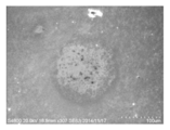
- FIG. 13 is an electron micrograph showing the ITO film partially peeled off by the rare metal peeling method of Embodiment 4 according to the present invention.
- the generation conditions of the functional cavitation MFC are the same as those in the first embodiment.
- the white portion of the upper third of FIG. 13 is not exposed to the functional cavitation MFC. For this reason, the ITO film remains on the glass substrate as it is.
- the lower part of about 2/3 is exposed to the functional cavitation MFC.
- fine particles containing components of the ITO film and lime soda glass (SO 2 , NaCO 3 , CaCO 3 ) constituting the glass substrate are formed.
- the melting point of lime soda glass is about 1270 K
- the functional cavitation MFC has reached a high temperature exceeding the melting point of lime soda glass, and is composed of rare metals In 2 O 3 and SnO 2. It can be seen that the ITO film can be easily peeled off. For this reason, it turns out that functional cavitation MFC can be effectively utilized for rare metal recovery.
- the ITO film when the ITO film is exposed together with the glass substrate only to the flow cavitation that does not irradiate the ultrasonic wave U1, the ITO film is not peeled off from the glass substrate, and as a whole, the upper side of FIG. It remained in the same state as about one third.
- an ITO film composed of a rare metal is deposited on the mechanical and electrochemical cavitation MFC generated by the method of generating mechanical and electrochemical cavitation in the first embodiment.
- the ITO film is peeled off from the glass surface by colliding with the surface of the glass as the coated material.
- the ITO film was peeled off by changing the flow rate of the flow cavitation by changing the distance from the spray nozzle 20 to the ITO film.
- the flow cavitation flow rates are (A) 5 m / s, (B) 21 m / s, (C) 80 m / s, and (D) 120 m / s, respectively.
- the ultrasonic wave U1 was irradiated and the state in which the ITO film was peeled was observed.
- the generation conditions of the functional cavitation MFC are the same as those in the first embodiment.
- FIG. 14 is a graph showing the relationship between the break threshold and the flow rate in a test for testing the effect of the method for generating mechanical and electrochemical cavitation MFC according to Embodiment 1 of the present invention.
- FIG. 15 is a field emission showing the test result when the flow velocity of flow cavitation is 4.5 m / s in a test for testing the effect of the method for generating mechanical and electrochemical cavitation MFC of Embodiment 1 according to the present invention.
- 3 is a scanning electron microscope (FE-SEM) photograph.
- FIG. 16 is a field emission scan showing a test result when the flow velocity of flow cavitation is 21 m / s in a test for testing the effect of the method for generating mechanical and electrochemical cavitation MFC of Embodiment 1 according to the present invention. It is an electron microscope (FE-SEM) photograph.
- FIG. 15 is a field emission showing the test result when the flow velocity of flow cavitation is 4.5 m / s in a test for testing the effect of the method for generating mechanical and electrochemical cavitation MFC of Embodiment 1 according to the present invention.
- 3 is a scanning electron microscope (FE-SEM) photograph.
- FIG. 16 is
- FIG. 17 is a field emission scan showing test results when the flow velocity of flow cavitation is 80 m / s in a test for testing the effect of the method for generating mechanical and electrochemical cavitation MFC according to Embodiment 1 of the present invention. It is an electron microscope (FE-SEM) photograph.
- FIG. 18 is a field emission scan showing a test result when the flow velocity of flow cavitation is 120 m / s in a test for testing the effect of the method for generating mechanical and electrochemical cavitation MFC according to Embodiment 1 of the present invention. It is an electron microscope (FE-SEM) photograph.
- the surface of the glass as the coating on which the ITO film is deposited is modified to be porous, As in the case where the flow velocity of flow cavitation is 5 m / s, the ITO film and the fine particles containing the components of lime soda glass (SO 2 , NaCO 3 , CaCO 3 ) constituting the glass substrate are uniformly formed. It can be seen that the ITO film cannot be sufficiently peeled off.
- the ITO film is partially damaged, but the flow cavitation flow rate is uniform as in the case of 5 m / s.
- the ITO film and fine particles containing components of lime soda glass (SO 2 , NaCO 3 , CaCO 3 ) constituting the glass substrate have not yet been formed, and the ITO film can be sufficiently peeled off. I understand that I can't.
- Embodiment 5 Next, a method for generating a deuterium fusion reaction according to Embodiment 5 of the present invention will be described.
- the fifth embodiment is different from the first embodiment in that heavy water or a liquid containing deuterium is used instead of the tap water W1 and the high-pressure water W2. Since the other points are the same as those of the first embodiment, description thereof is omitted.
- the liquid flows against the flow cavitation caused by the jet of the liquid containing heavy water or deuterium.
- the ultrasonic wave U1 is irradiated from the ultrasonic irradiation element 30 to a position where the flow rate of cavitation becomes 5 m / s or less.
- the high-temperature reaction field of the flow cavitation including the high-temperature reaction field which is caused by repeated expansion and contraction by ultrasonic irradiation, is distributed at a position away from the injection nozzle, and at the distributed position, the cavitation collapses. Generates a deuterium fusion reaction.
- Method for generating mechanical and electrochemical cavitation according to the present invention, method for changing the geometrical shape and electrochemical properties of the surface of a material, method for stripping rare metals, apparatus for generating mechanical and electrochemical cavitation
- the method for generating the deuterium fusion reaction is not limited to the contents of Embodiments 1 to 4 described above, and various modifications and changes as described below are possible.
- the configuration of the apparatus used in the method for generating mechanical and electrochemical cavitation is not limited to the configuration of the apparatus of the above-described embodiment.
- the injection nozzle is composed of a horn nozzle, it is not limited to this.
- the ultrasonic irradiation element 30 irradiated the ultrasonic wave U1 with respect to the water jet from the horizontal direction with respect to the water jet injected vertically downward, it is not limited to this structure.
- the ultrasonic wave U1 may be irradiated from a direction nearly parallel to the water jet.
- tap water W1 was used in this embodiment, it is not limited to this.
- ultrapure water or pure water may be used instead of tap water.
- an organic solvent such as acetone may be used instead of tap water.
- the colliding object 41A is made of, for example, a flat plate-like or curved plate-like stainless steel, but is not limited thereto.
- the carbon steel SS400 plate material is used as the surface-modified substance, but is not limited thereto.
- the ITO film is peeled from the glass substrate, but the present invention is not limited to this. That is, the rare metal is not limited to the ITO film, and the coating is not limited to the glass substrate.
- the present invention can be used in a field that utilizes a high-temperature reaction field of flow cavitation, for example, a field that modifies the surface of a substance by polishing the surface of the substance or making the surface of the substance porous. It can be widely applied in the field of fusion reactions in high temperature reaction fields.
Landscapes
- Engineering & Computer Science (AREA)
- Physics & Mathematics (AREA)
- Mechanical Engineering (AREA)
- General Engineering & Computer Science (AREA)
- Plasma & Fusion (AREA)
- High Energy & Nuclear Physics (AREA)
- Fluid Mechanics (AREA)
- Catalysts (AREA)
- Powder Metallurgy (AREA)
- Oxygen, Ozone, And Oxides In General (AREA)
- Physical Water Treatments (AREA)
Abstract
Description
図1は、本発明による実施形態1の機械的及び電気化学的キャビテーションMFCを発生させる方法を示す概略図である。
また、白金、酸化ニッケル(II)の粒子は、0.1μm以上85μm以下の粒径を有している。白金、酸化ニッケル(II)の粒子についても、酸化チタンの場合と同様に、表面改質を効率的に行うためには、粒径が小さいことが好ましい。白金、酸化ニッケル(II)の粒径が85μmを超える場合には、白金、酸化ニッケル(II)の表面改質を効率的に行うことが困難となる。白金、酸化ニッケル(II)の粒径が0.1μm未満の場合には、粒子が小さすぎて、表面を微細化して多孔質構造とする表面改質を効率的に行うことが困難となる。
即ち、気泡振動(キャビテーションの核への振動)の共振周波数を与える半径を、共鳴半径と呼ぶが、音圧(超音波出力)が大きいと、共鳴半径以上では、キャビテーションの核はあまり膨張せず、レイリー収縮(断熱圧縮)を生じさせない。一方、音圧をBlake閾値とする(等温膨張に必要な音圧とする)気泡半径以下でも、気泡の膨張は小さくなる。これらのことから、一般にレイリー収縮を起こすような活性な気泡の平衡半径は、Blake閾値と共鳴半径の間にあるためである。
水蒸気圧をpvとし、雰囲気圧をpoとし、表面張力をσとし、平衡半径をR0としたときに、キャビテーションの核が膨張するために必要な最小圧力は、以下の式により求められる。


図2に示すグラフより、平衡半径が1μmより大きい場合には、ブレーク閾値は1bar(大気圧)に等しくなり、容易に膨張させることが可能になる。ここで、液体密度をρとし、液体の流速をνとし、振動速度をν0として、ベルヌーイの定理を用いると、気泡膨張に必要な音圧は、

図3に示すグラフより、流速νが4.52m/sのときに、ノズルから離間した位置において、ブレーク閾値ABlakeは1barに等しくなる。このように、液体の流速、即ち、流動キャビテーションの流速が、所定の移動速度である5m/s以下になる位置においては、音圧が低くてもキャビテーションの核は膨張することができることが分かる。図3に示すように、流動キャビテーションの流速が、所定の移動速度である5m/sを超える位置の辺りからブレーク閾値ABlakeは急に大きくなり、噴射ノズル20に近づいて流動キャビテーションの流速が高くなる程、ブレーク閾値ABlakeは大きくなり、キャビテーションの核を膨張させるためには、大きな音圧が必要になることが分かる。

ウォータージェットキャビテーションのサイズである100μm以上の気泡では、共振周波数は33kHz以下となり、例えば、超音波照射素子30から照射される超音波U1の周波数を28kHzとすることより,気泡を膨張させ活性化するのに有効であると考えられる。
噴射ノズル20は、リアクター10に貯留されている水道水W1に浸漬された状態で、高圧水W2を水道水W1に対して噴射することによるウォータージェットを噴射する。これにより、ウォータージェットにおいて循環渦が発生する。循環渦においては核(キャビテーション核)が発生する。核の中心の圧力が、ウォータージェットの温度における飽和蒸気圧に達すると、流動キャビテーションが発生する。
図5は、本発明による実施形態1の機械的及び電気化学的キャビテーションにより、多孔質状とされ白金を包み込むように保持している状態とされた酸化チタンの表面を示す電界放射型走査電子顕微鏡(FE-SEM)写真である。図6は、本発明による実施形態1の機械的及び電気化学的キャビテーションMFCにより、多孔質状とされ白金を包み込むように保持している状態とされた酸化チタンの表面を示す電界放射型走査電子顕微鏡(FE-SEM)写真である。図7は、本発明による実施形態1の機械的及び電気化学的キャビテーションMFCにより、多孔質状とされ白金を包み込むように保持している状態とされた酸化チタンの表面を示す電界放射型走査電子顕微鏡(FE-SEM)写真である。図8は、本発明による実施形態1の機械的及び電気化学的キャビテーションMFCにより、多孔質状とされ白金を包み込むように保持している状態とされた酸化チタンの表面を示す電界放射型走査電子顕微鏡(FE-SEM)写真である。図9は、本発明による実施形態1の機械的及び電気化学的キャビテーションMFCにより、多孔質状とされ白金を包み込むように保持している状態とされた酸化チタンの表面を示す電界放射型走査電子顕微鏡(FE-SEM)写真である。
(機能性キャビテーションMFC発生条件)
高圧水供給源から噴射ノズル20へ供給される高圧水の圧力 : 35MPa
超音波U1の照射及びウォータージェットの噴射時間 : 2分
超音波U1の周波数 : 28kHz
超音波出力定格値 : 225W
ウォータージェットから超音波照射素子30までの距離 : 54mm
図10に示すように、流動キャビテーションによる表面改質が行われた酸化チタンの表面は、図5~図9に示す程の多孔質状を有していないことが分かる。また、白金の粒子は、酸化チタンの表面に付着しているような状態であり、白金の粒子が酸化チタンに包み込まれるようにして酸化チタンに坦持されている状態とは大きく異なることが分かる。


即ち、半導体電極として酸化チタン(TiO2)、金属電極として白金(Pt)を用い、半導体電極に紫外線を照射すると、本多-藤嶋効果により、半導体電極から酸素(O2)が発生し、金属電極から水素(H2)が発生する。このとき金属電極には、-0.5V程度の外部バイアス電圧をかける必要があったが、水の理論電解電圧1.23Vよりも遥かに低い電圧で、水が水素と酸素とに分解される。
機能性キャビテーションMFCによる表面処理を酸化チタンにより構成される半導体電極や白金により構成される金属電極に施すと、バイアス電圧なしで水の光分解を起こすことが可能となる。また紫外線の照射のみならず、可視光(太陽光)の照射によっても、高いエネルギー変換効率で水素を発生させることが可能となる。また、機能性キャビテーションMFCによる物質の表面改質による高機能化を、酸化チタンや白金のみならず、他分野の物質にも適用可能である。
次に、本発明に係る機械的及び電気化学的キャビテーションを発生させる方法について説明する。実施形態2では、ウォータージェットが被衝突物に対して噴出され衝突される点において、実施形態1とは異なる。これ以外の点については、実施形態1と同一であるため、同一の部材については、同一の符号を付すこととし、説明を省略する。図12は、本発明による実施形態2の機械的及び電気化学的キャビテーションMFCを発生させる方法を示す概略図である。
次に、本発明の実施形態3に係る、物質の表面の幾何学的形状および電気化学的性質を変化させる方法について説明する。実施形態3では、表面改質される物質として、酸化チタン及び白金に代えて、ガス吸着が少なく、高い耐酸化性及び耐食性が要求される物質が用いられる点において、実施形態1とは異なる。これ以外の点については、実施形態2と同一であるため、同一の部材については、同一の符号を付すこととし、説明を省略する。
次に、本発明の実施形態4に係る、レアメタルを剥離する方法について説明する。実施形態4では、液晶ディスプレイの透明電極に用いられるITO膜に対して、機能性キャビテーションMFCが作用する点において、実施形態3とは異なる。これ以外の点については、実施形態3と同一であるため、同一の部材については、同一の符号を付すこととし、説明を省略する。
次に、本発明の実施形態5に係る、重水素の核融合反応を発生させる方法について説明する。実施形態5では、水道水W1及び高圧水W2に代えて、重水、もしくは、重水素を含む液体が用いられる点において、実施形態1とは異なる。これ以外の点については、実施形態1と同一であるため説明を省略する。
20 噴射ノズル
30 超音波照射素子
41A 被衝突物
MFC 機能性キャビテーション(機械的及び電気化学的キャビテーション)
U1 超音波
W1 水道水
W2 高圧水
Claims (11)
- 水中に浸漬させた噴射ノズルからウォータージェットを噴射させると共に、前記ウォータージェットの噴射に伴い生じる流動キャビテーションに対して、前記流動キャビテーションが膨張可能な、前記流動キャビテーションの流速が所定の移動速度以下になる位置に超音波を照射して、前記超音波の照射で膨張・収縮を繰り返すことにより生ずる、高温反応場を含んだ前記流動キャビテーションの前記高温反応場を前記噴射ノズルから離間した位置に分布させる、機械的及び電気化学的キャビテーションを発生させる方法。
- 前記流動キャビテーションの移動速度は、5m/s以下である請求項1に記載の、機械的及び電気化学的キャビテーションを発生させる方法。
- 前記超音波の周波数は、20kHz以上33kHz以下である請求項1に記載の、機械的及び電気化学的キャビテーションを発生させる方法。
- 前記超音波を照射する超音波照射素子から前記ウォータージェットまでの距離は、前記超音波の5波長以下である請求項1又は請求項2に記載の、機械的及び電気化学的キャビテーションを発生させる方法。
- 前記噴射ノズルから噴射される前記ウォータージェットを被衝突物に衝突させることによって前記被衝突物の周辺に生じる2次噴流の流動キャビテーションに対して、前記超音波を照射することにより、高温反応場を含んだ前記流動キャビテーションの前記高温反応場を、前記被衝突物の周辺に発生させる請求項1~請求項4のいずれかに記載の、機械的及び電気化学的キャビテーションを発生させる方法。
- 請求項1~請求項5のいずれかに記載の、機械的及び電気化学的キャビテーションを発生させる方法により発生した機械的及び電気化学的キャビテーションを、物質に衝突させて、物質の表面の幾何学的形状および電気化学的性質を変化させる方法。
- 前記物質は、ルチル型又はアナターゼ型の結晶構造を有する酸化チタン、白金、及び、酸化ニッケルのうちから選択された少なくとも1つにより構成され、
前記酸化チタンの粒子は、100nm以上400nm以下の粒径を有し、
前記白金、又は、前記酸化ニッケルの粒子は、0.1μm以上85μm以下の粒径を有する、請求項6に記載の、物質の表面の幾何学的形状および電気化学的性質を変化させる方法。 - 前記物質の表面において、ガス吸着が少なく、耐酸化性及び耐食性が高い不活性表面を生成する、請求項6に記載の、物質の表面の幾何学的形状および電気化学的性質を変化させる方法。
- 請求項1~請求項5のいずれかに記載の、機械的及び電気化学的キャビテーションを発生させる方法により発生した機械的及び電気化学的キャビテーションを、レアメタルが蒸着された被覆物の表面に衝突させて、前記被覆物の表面から前記レアメタルを剥離する方法。
- 水中に浸漬されウォータージェットを噴射する噴射ノズルと、
前記ウォータージェットの噴射に伴い生じる流動キャビテーションに対して、前記流動キャビテーションが膨張可能な、前記流動キャビテーションの流速が所定の移動速度以下になる位置に超音波を照射して、前記超音波の照射で膨張・収縮を繰り返すことにより生ずる、高温反応場を含んだ前記流動キャビテーションの前記高温反応場を前記噴射ノズルから離間した位置に分布させる超音波照射素子と、を備える、機械的及び電気化学的キャビテーションの発生装置。 - 重水もしくは重水素を含む液体に浸漬させた噴射ノズルから重水もしくは重水素を含む液体を噴射させると共に、前記重水もしくは重水素を含む液体の噴射に伴い生じる流動キャビテーションに対して、前記流動キャビテーションが膨張可能な、前記流動キャビテーションの流速が所定の移動速度以下になる位置に超音波を照射して、前記超音波の照射で膨張・収縮を繰り返すことにより生ずる、高温反応場を含んだ前記流動キャビテーションの前記高温反応場を前記噴射ノズルから離間した位置に分布させ、キャビテーションの崩壊により重水素の核融合反応を発生させる方法。
Priority Applications (2)
| Application Number | Priority Date | Filing Date | Title |
|---|---|---|---|
| US15/552,777 US10590966B2 (en) | 2015-02-24 | 2016-02-22 | Method for generating mechanical and electrochemical cavitation, method for changing geometric shape and electrochemical properties of substance surface, method for peeling off rare metal, mechanical and electrochemical cavitation generator, and method for generating nuclear fusion reaction of deuterium |
| JP2017502344A JP6629828B2 (ja) | 2015-02-24 | 2016-02-22 | 機械的及び電気化学的キャビテーションを発生させる方法、物質の表面の幾何学的形状および電気化学的性質を変化させる方法、レアメタルを剥離する方法、及び、機械的及び電気化学的キャビテーションの発生装置 |
Applications Claiming Priority (2)
| Application Number | Priority Date | Filing Date | Title |
|---|---|---|---|
| JP2015-034142 | 2015-02-24 | ||
| JP2015034142 | 2015-02-24 |
Publications (1)
| Publication Number | Publication Date |
|---|---|
| WO2016136656A1 true WO2016136656A1 (ja) | 2016-09-01 |
Family
ID=56788354
Family Applications (1)
| Application Number | Title | Priority Date | Filing Date |
|---|---|---|---|
| PCT/JP2016/055016 Ceased WO2016136656A1 (ja) | 2015-02-24 | 2016-02-22 | 機械的及び電気化学的キャビテーションを発生させる方法、物質の表面の幾何学的形状および電気化学的性質を変化させる方法、レアメタルを剥離する方法、機械的及び電気化学的キャビテーションの発生装置、及び、重水素の核融合反応を発生させる方法 |
Country Status (3)
| Country | Link |
|---|---|
| US (1) | US10590966B2 (ja) |
| JP (1) | JP6629828B2 (ja) |
| WO (1) | WO2016136656A1 (ja) |
Cited By (1)
| Publication number | Priority date | Publication date | Assignee | Title |
|---|---|---|---|---|
| JP2019130599A (ja) * | 2018-01-29 | 2019-08-08 | 公立大学法人山陽小野田市立山口東京理科大学 | 超高温高圧キャビテーションを発生させる方法、物質の表面に圧縮残留応力を付与するとともに、表面の幾何学的形状、機械的特性および耐食性を変化させる方法、及び、超高温高圧キャビテーションの発生装置 |
Families Citing this family (3)
| Publication number | Priority date | Publication date | Assignee | Title |
|---|---|---|---|---|
| US20190139652A1 (en) * | 2016-05-03 | 2019-05-09 | Roger Sherman Stringham | Cavitation Heater |
| JP6801805B1 (ja) * | 2020-06-22 | 2020-12-16 | マツダ株式会社 | 計測方法及び計測装置、並びに、被覆金属材の耐食性試験方法及び耐食性試験装置 |
| CN113695690B (zh) * | 2021-09-06 | 2023-05-09 | 长春理工大学 | 水射流辅助微细电解加工异形孔装置及工作方法 |
Citations (5)
| Publication number | Priority date | Publication date | Assignee | Title |
|---|---|---|---|---|
| JPH07201799A (ja) * | 1993-12-17 | 1995-08-04 | Internatl Business Mach Corp <Ibm> | 半導体ウエハー洗浄装置 |
| JP2006255865A (ja) * | 2005-03-18 | 2006-09-28 | Tohoku Univ | 金属材料や半導体材料等の表面改質法とそのための表面改質装置と、加工能力の高いキャビテーション・ショットレス・ピーニング法 |
| JP2007059318A (ja) * | 2005-08-26 | 2007-03-08 | Hideo Sugai | プラズマ発生装置 |
| JP2009090443A (ja) * | 2007-10-12 | 2009-04-30 | Toshiba Plant Systems & Services Corp | 表面改質装置およびその改質方法 |
| JP2010523985A (ja) * | 2007-04-04 | 2010-07-15 | シナジー イノベーションズ インコーポレイテッド | 制御された核反応のために、レーザーナノ粒子核形成された空洞に液滴衝突による強制崩壊を発生させるシステム及び方法 |
Family Cites Families (1)
| Publication number | Priority date | Publication date | Assignee | Title |
|---|---|---|---|---|
| US9932246B2 (en) * | 2013-03-15 | 2018-04-03 | Fluid-Quip, Inc. | Pulse cavitation processor and method of using same |
-
2016
- 2016-02-22 WO PCT/JP2016/055016 patent/WO2016136656A1/ja not_active Ceased
- 2016-02-22 US US15/552,777 patent/US10590966B2/en not_active Expired - Fee Related
- 2016-02-22 JP JP2017502344A patent/JP6629828B2/ja active Active
Patent Citations (5)
| Publication number | Priority date | Publication date | Assignee | Title |
|---|---|---|---|---|
| JPH07201799A (ja) * | 1993-12-17 | 1995-08-04 | Internatl Business Mach Corp <Ibm> | 半導体ウエハー洗浄装置 |
| JP2006255865A (ja) * | 2005-03-18 | 2006-09-28 | Tohoku Univ | 金属材料や半導体材料等の表面改質法とそのための表面改質装置と、加工能力の高いキャビテーション・ショットレス・ピーニング法 |
| JP2007059318A (ja) * | 2005-08-26 | 2007-03-08 | Hideo Sugai | プラズマ発生装置 |
| JP2010523985A (ja) * | 2007-04-04 | 2010-07-15 | シナジー イノベーションズ インコーポレイテッド | 制御された核反応のために、レーザーナノ粒子核形成された空洞に液滴衝突による強制崩壊を発生させるシステム及び方法 |
| JP2009090443A (ja) * | 2007-10-12 | 2009-04-30 | Toshiba Plant Systems & Services Corp | 表面改質装置およびその改質方法 |
Non-Patent Citations (1)
| Title |
|---|
| Y. TORIYABE ET AL.: "Acceleration of the d+d reaction in metal lithium acoustic cavitation with deuteronbombardment from 30 to 70 keV, Physical Review C", PHYS. REV., vol. C85, 24 May 2012 (2012-05-24), pages 054620 * |
Cited By (2)
| Publication number | Priority date | Publication date | Assignee | Title |
|---|---|---|---|---|
| JP2019130599A (ja) * | 2018-01-29 | 2019-08-08 | 公立大学法人山陽小野田市立山口東京理科大学 | 超高温高圧キャビテーションを発生させる方法、物質の表面に圧縮残留応力を付与するとともに、表面の幾何学的形状、機械的特性および耐食性を変化させる方法、及び、超高温高圧キャビテーションの発生装置 |
| JP7157994B2 (ja) | 2018-01-29 | 2022-10-21 | 公立大学法人山陽小野田市立山口東京理科大学 | 超高温高圧キャビテーションを発生させる方法、物質の表面に圧縮残留応力を付与するとともに、表面の幾何学的形状、機械的特性および耐食性を変化させる方法、及び、超高温高圧キャビテーションの発生装置 |
Also Published As
| Publication number | Publication date |
|---|---|
| JPWO2016136656A1 (ja) | 2017-12-07 |
| JP6629828B2 (ja) | 2020-01-15 |
| US20180274569A1 (en) | 2018-09-27 |
| US10590966B2 (en) | 2020-03-17 |
Similar Documents
| Publication | Publication Date | Title |
|---|---|---|
| Wang et al. | Catalyst preparation with plasmas: how does it work? | |
| Bogaerts et al. | Plasma technology: an emerging technology for energy storage | |
| Kyriakou et al. | Plasma driven exsolution for nanoscale functionalization of perovskite oxides | |
| Levchenko et al. | Lightning under water: Diverse reactive environments and evidence of synergistic effects for material treatment and activation | |
| JP6629828B2 (ja) | 機械的及び電気化学的キャビテーションを発生させる方法、物質の表面の幾何学的形状および電気化学的性質を変化させる方法、レアメタルを剥離する方法、及び、機械的及び電気化学的キャビテーションの発生装置 | |
| JP5472601B2 (ja) | 液中プラズマ処理装置、金属ナノ粒子製造方法及び金属担持物製造方法 | |
| Zhou et al. | Combining non-thermal plasma technology with photocatalysis: a critical review | |
| US9738529B2 (en) | Method to reduce CO2 to CO using plasmon-enhanced photocatalysis | |
| Wang et al. | Sonochemical hydrogen production efficiently catalyzed by Au/TiO2 | |
| Yan et al. | Efficient and rapid hydrogen extraction from ammonia–water via laser under ambient conditions without catalyst | |
| JP2011218293A (ja) | 排ガスの処理装置 | |
| Yang et al. | CO2 reduction to higher hydrocarbons by plasma discharge in carbonated water | |
| Xin et al. | Hydrogen production from ethanol solution by pulsed discharge with TiO2 catalysts | |
| Fridman | Plasma Science and Technology: Lectures in Physics, Chemistry, Biology, and Engineering | |
| Xia et al. | Enhancing CO2 conversion via atmospheric pressure glow discharge plasma jet coupled with catalysts | |
| Tai et al. | Plasma Meets Graphene: Surface Engineering and Functionalities | |
| JP6112704B2 (ja) | 貴金属担持光触媒粒子の製造方法 | |
| Tian et al. | A review of cold plasma for catalyst synthesis and modification. Clean Energy Science and Technology. 2024; 2 (1): 131 | |
| Yoshimura et al. | Nanolevel surface processing of fine particles by waterjet cavitation and multifunction cavitation to improve the photocatalytic properties of titanium oxide | |
| Chen et al. | Role of plasma catalysis in the microwave plasma‐assisted conversion of CO2 | |
| Liu et al. | Effect of Pd crystal facet on the reaction of oxygen-promoted hydrogen evolution from formaldehyde driven by visible light | |
| Tekin et al. | Photoelectrocatalytic decomposition of Acid Black 1 dye using TiO2 nanotubes | |
| JP5390315B2 (ja) | 金属担持物製造装置及び金属担持物製造方法 | |
| Yuji et al. | Surface Treatment of $\hbox {TiO} _ {2} $ Films by Pulse Plasma for Dye-Sensitized Solar Cells Application | |
| Bishwakarma et al. | Strategies for Synthesizing Metal Oxide Nanoparticles and the Challenges |
Legal Events
| Date | Code | Title | Description |
|---|---|---|---|
| 121 | Ep: the epo has been informed by wipo that ep was designated in this application |
Ref document number: 16755402 Country of ref document: EP Kind code of ref document: A1 |
|
| ENP | Entry into the national phase |
Ref document number: 2017502344 Country of ref document: JP Kind code of ref document: A |
|
| WWE | Wipo information: entry into national phase |
Ref document number: 15552777 Country of ref document: US |
|
| NENP | Non-entry into the national phase |
Ref country code: DE |
|
| 122 | Ep: pct application non-entry in european phase |
Ref document number: 16755402 Country of ref document: EP Kind code of ref document: A1 |