WO2016136267A1 - Refrigeration apparatus for containers - Google Patents
Refrigeration apparatus for containers Download PDFInfo
- Publication number
- WO2016136267A1 WO2016136267A1 PCT/JP2016/001026 JP2016001026W WO2016136267A1 WO 2016136267 A1 WO2016136267 A1 WO 2016136267A1 JP 2016001026 W JP2016001026 W JP 2016001026W WO 2016136267 A1 WO2016136267 A1 WO 2016136267A1
- Authority
- WO
- WIPO (PCT)
- Prior art keywords
- air
- outside
- container
- space
- storage space
- Prior art date
Links
- 238000005057 refrigeration Methods 0.000 title claims abstract description 41
- 238000003860 storage Methods 0.000 claims abstract description 98
- 239000000203 mixture Substances 0.000 claims abstract description 44
- 239000003507 refrigerant Substances 0.000 claims abstract description 29
- IJGRMHOSHXDMSA-UHFFFAOYSA-N Atomic nitrogen Chemical compound N#N IJGRMHOSHXDMSA-UHFFFAOYSA-N 0.000 claims description 153
- 229910052757 nitrogen Inorganic materials 0.000 claims description 78
- 239000007789 gas Substances 0.000 claims description 45
- XLYOFNOQVPJJNP-UHFFFAOYSA-N water Substances O XLYOFNOQVPJJNP-UHFFFAOYSA-N 0.000 claims description 42
- 238000011144 upstream manufacturing Methods 0.000 claims description 12
- 230000029058 respiratory gaseous exchange Effects 0.000 claims description 9
- 238000007599 discharging Methods 0.000 claims description 6
- 230000000149 penetrating effect Effects 0.000 claims description 2
- 238000004891 communication Methods 0.000 abstract description 3
- 238000004378 air conditioning Methods 0.000 abstract 2
- QVGXLLKOCUKJST-UHFFFAOYSA-N atomic oxygen Chemical compound [O] QVGXLLKOCUKJST-UHFFFAOYSA-N 0.000 description 136
- 239000001301 oxygen Substances 0.000 description 136
- 229910052760 oxygen Inorganic materials 0.000 description 136
- CURLTUGMZLYLDI-UHFFFAOYSA-N Carbon dioxide Chemical compound O=C=O CURLTUGMZLYLDI-UHFFFAOYSA-N 0.000 description 104
- 238000001179 sorption measurement Methods 0.000 description 98
- 230000007246 mechanism Effects 0.000 description 68
- 229910002092 carbon dioxide Inorganic materials 0.000 description 52
- 239000001569 carbon dioxide Substances 0.000 description 52
- 238000009833 condensation Methods 0.000 description 38
- 230000005494 condensation Effects 0.000 description 38
- 239000003463 adsorbent Substances 0.000 description 28
- 238000005259 measurement Methods 0.000 description 25
- 241000196324 Embryophyta Species 0.000 description 20
- 238000009826 distribution Methods 0.000 description 16
- 238000005192 partition Methods 0.000 description 11
- 230000009467 reduction Effects 0.000 description 9
- 239000012528 membrane Substances 0.000 description 6
- 229910021536 Zeolite Inorganic materials 0.000 description 5
- 238000001816 cooling Methods 0.000 description 5
- 230000007797 corrosion Effects 0.000 description 5
- 238000005260 corrosion Methods 0.000 description 5
- 230000007423 decrease Effects 0.000 description 5
- 238000010586 diagram Methods 0.000 description 5
- HNPSIPDUKPIQMN-UHFFFAOYSA-N dioxosilane;oxo(oxoalumanyloxy)alumane Chemical compound O=[Si]=O.O=[Al]O[Al]=O HNPSIPDUKPIQMN-UHFFFAOYSA-N 0.000 description 5
- 239000010457 zeolite Substances 0.000 description 5
- 238000003795 desorption Methods 0.000 description 4
- 239000003921 oil Substances 0.000 description 4
- 239000011148 porous material Substances 0.000 description 4
- 238000010926 purge Methods 0.000 description 4
- 238000005452 bending Methods 0.000 description 3
- 230000008859 change Effects 0.000 description 3
- 241000234295 Musa Species 0.000 description 2
- 244000025272 Persea americana Species 0.000 description 2
- 235000008673 Persea americana Nutrition 0.000 description 2
- 238000009530 blood pressure measurement Methods 0.000 description 2
- 238000007664 blowing Methods 0.000 description 2
- 230000006837 decompression Effects 0.000 description 2
- 230000005484 gravity Effects 0.000 description 2
- 239000011810 insulating material Substances 0.000 description 2
- QJGQUHMNIGDVPM-UHFFFAOYSA-N nitrogen group Chemical group [N] QJGQUHMNIGDVPM-UHFFFAOYSA-N 0.000 description 2
- 230000002093 peripheral effect Effects 0.000 description 2
- 230000035699 permeability Effects 0.000 description 2
- 229910000838 Al alloy Inorganic materials 0.000 description 1
- OKTJSMMVPCPJKN-UHFFFAOYSA-N Carbon Chemical compound [C] OKTJSMMVPCPJKN-UHFFFAOYSA-N 0.000 description 1
- 235000018290 Musa x paradisiaca Nutrition 0.000 description 1
- 238000010521 absorption reaction Methods 0.000 description 1
- 235000021015 bananas Nutrition 0.000 description 1
- 230000015572 biosynthetic process Effects 0.000 description 1
- 230000000903 blocking effect Effects 0.000 description 1
- 229910052799 carbon Inorganic materials 0.000 description 1
- 150000001768 cations Chemical class 0.000 description 1
- 235000013339 cereals Nutrition 0.000 description 1
- 239000003795 chemical substances by application Substances 0.000 description 1
- 230000006835 compression Effects 0.000 description 1
- 238000007906 compression Methods 0.000 description 1
- 239000012141 concentrate Substances 0.000 description 1
- 238000004320 controlled atmosphere Methods 0.000 description 1
- 230000000694 effects Effects 0.000 description 1
- 230000005684 electric field Effects 0.000 description 1
- 239000008151 electrolyte solution Substances 0.000 description 1
- 235000012055 fruits and vegetables Nutrition 0.000 description 1
- 238000003306 harvesting Methods 0.000 description 1
- 239000010687 lubricating oil Substances 0.000 description 1
- 238000012423 maintenance Methods 0.000 description 1
- 238000004519 manufacturing process Methods 0.000 description 1
- 150000002829 nitrogen Chemical class 0.000 description 1
- 235000015097 nutrients Nutrition 0.000 description 1
- 230000000241 respiratory effect Effects 0.000 description 1
- 239000013535 sea water Substances 0.000 description 1
- 238000005507 spraying Methods 0.000 description 1
- 230000007704 transition Effects 0.000 description 1
- 235000013311 vegetables Nutrition 0.000 description 1
- 239000002351 wastewater Substances 0.000 description 1
Images


Classifications
-
- F—MECHANICAL ENGINEERING; LIGHTING; HEATING; WEAPONS; BLASTING
- F25—REFRIGERATION OR COOLING; COMBINED HEATING AND REFRIGERATION SYSTEMS; HEAT PUMP SYSTEMS; MANUFACTURE OR STORAGE OF ICE; LIQUEFACTION SOLIDIFICATION OF GASES
- F25D—REFRIGERATORS; COLD ROOMS; ICE-BOXES; COOLING OR FREEZING APPARATUS NOT OTHERWISE PROVIDED FOR
- F25D17/00—Arrangements for circulating cooling fluids; Arrangements for circulating gas, e.g. air, within refrigerated spaces
- F25D17/04—Arrangements for circulating cooling fluids; Arrangements for circulating gas, e.g. air, within refrigerated spaces for circulating air, e.g. by convection
- F25D17/042—Air treating means within refrigerated spaces
-
- A—HUMAN NECESSITIES
- A23—FOODS OR FOODSTUFFS; TREATMENT THEREOF, NOT COVERED BY OTHER CLASSES
- A23B—PRESERVING, e.g. BY CANNING, MEAT, FISH, EGGS, FRUIT, VEGETABLES, EDIBLE SEEDS; CHEMICAL RIPENING OF FRUIT OR VEGETABLES; THE PRESERVED, RIPENED, OR CANNED PRODUCTS
- A23B7/00—Preservation or chemical ripening of fruit or vegetables
- A23B7/04—Freezing; Subsequent thawing; Cooling
- A23B7/0425—Freezing; Subsequent thawing; Cooling the material not being transported through or in the apparatus, with or without shaping, e.g. in the form of powder, granules or flakes
-
- A—HUMAN NECESSITIES
- A23—FOODS OR FOODSTUFFS; TREATMENT THEREOF, NOT COVERED BY OTHER CLASSES
- A23B—PRESERVING, e.g. BY CANNING, MEAT, FISH, EGGS, FRUIT, VEGETABLES, EDIBLE SEEDS; CHEMICAL RIPENING OF FRUIT OR VEGETABLES; THE PRESERVED, RIPENED, OR CANNED PRODUCTS
- A23B7/00—Preservation or chemical ripening of fruit or vegetables
- A23B7/14—Preserving or ripening with chemicals not covered by groups A23B7/08 or A23B7/10
- A23B7/144—Preserving or ripening with chemicals not covered by groups A23B7/08 or A23B7/10 in the form of gases, e.g. fumigation; Compositions or apparatus therefor
- A23B7/148—Preserving or ripening with chemicals not covered by groups A23B7/08 or A23B7/10 in the form of gases, e.g. fumigation; Compositions or apparatus therefor in a controlled atmosphere, e.g. partial vacuum, comprising only CO2, N2, O2 or H2O
-
- B—PERFORMING OPERATIONS; TRANSPORTING
- B65—CONVEYING; PACKING; STORING; HANDLING THIN OR FILAMENTARY MATERIAL
- B65D—CONTAINERS FOR STORAGE OR TRANSPORT OF ARTICLES OR MATERIALS, e.g. BAGS, BARRELS, BOTTLES, BOXES, CANS, CARTONS, CRATES, DRUMS, JARS, TANKS, HOPPERS, FORWARDING CONTAINERS; ACCESSORIES, CLOSURES, OR FITTINGS THEREFOR; PACKAGING ELEMENTS; PACKAGES
- B65D88/00—Large containers
- B65D88/74—Large containers having means for heating, cooling, aerating or other conditioning of contents
- B65D88/745—Large containers having means for heating, cooling, aerating or other conditioning of contents blowing or injecting heating, cooling or other conditioning fluid inside the container
-
- F—MECHANICAL ENGINEERING; LIGHTING; HEATING; WEAPONS; BLASTING
- F25—REFRIGERATION OR COOLING; COMBINED HEATING AND REFRIGERATION SYSTEMS; HEAT PUMP SYSTEMS; MANUFACTURE OR STORAGE OF ICE; LIQUEFACTION SOLIDIFICATION OF GASES
- F25D—REFRIGERATORS; COLD ROOMS; ICE-BOXES; COOLING OR FREEZING APPARATUS NOT OTHERWISE PROVIDED FOR
- F25D11/00—Self-contained movable devices, e.g. domestic refrigerators
- F25D11/003—Transport containers
-
- F—MECHANICAL ENGINEERING; LIGHTING; HEATING; WEAPONS; BLASTING
- F25—REFRIGERATION OR COOLING; COMBINED HEATING AND REFRIGERATION SYSTEMS; HEAT PUMP SYSTEMS; MANUFACTURE OR STORAGE OF ICE; LIQUEFACTION SOLIDIFICATION OF GASES
- F25D—REFRIGERATORS; COLD ROOMS; ICE-BOXES; COOLING OR FREEZING APPARATUS NOT OTHERWISE PROVIDED FOR
- F25D17/00—Arrangements for circulating cooling fluids; Arrangements for circulating gas, e.g. air, within refrigerated spaces
- F25D17/04—Arrangements for circulating cooling fluids; Arrangements for circulating gas, e.g. air, within refrigerated spaces for circulating air, e.g. by convection
- F25D17/042—Air treating means within refrigerated spaces
- F25D17/045—Air flow control arrangements
-
- F—MECHANICAL ENGINEERING; LIGHTING; HEATING; WEAPONS; BLASTING
- F25—REFRIGERATION OR COOLING; COMBINED HEATING AND REFRIGERATION SYSTEMS; HEAT PUMP SYSTEMS; MANUFACTURE OR STORAGE OF ICE; LIQUEFACTION SOLIDIFICATION OF GASES
- F25D—REFRIGERATORS; COLD ROOMS; ICE-BOXES; COOLING OR FREEZING APPARATUS NOT OTHERWISE PROVIDED FOR
- F25D17/00—Arrangements for circulating cooling fluids; Arrangements for circulating gas, e.g. air, within refrigerated spaces
- F25D17/04—Arrangements for circulating cooling fluids; Arrangements for circulating gas, e.g. air, within refrigerated spaces for circulating air, e.g. by convection
- F25D17/06—Arrangements for circulating cooling fluids; Arrangements for circulating gas, e.g. air, within refrigerated spaces for circulating air, e.g. by convection by forced circulation
-
- F—MECHANICAL ENGINEERING; LIGHTING; HEATING; WEAPONS; BLASTING
- F25—REFRIGERATION OR COOLING; COMBINED HEATING AND REFRIGERATION SYSTEMS; HEAT PUMP SYSTEMS; MANUFACTURE OR STORAGE OF ICE; LIQUEFACTION SOLIDIFICATION OF GASES
- F25D—REFRIGERATORS; COLD ROOMS; ICE-BOXES; COOLING OR FREEZING APPARATUS NOT OTHERWISE PROVIDED FOR
- F25D21/00—Defrosting; Preventing frosting; Removing condensed or defrost water
- F25D21/14—Collecting or removing condensed and defrost water; Drip trays
-
- F—MECHANICAL ENGINEERING; LIGHTING; HEATING; WEAPONS; BLASTING
- F25—REFRIGERATION OR COOLING; COMBINED HEATING AND REFRIGERATION SYSTEMS; HEAT PUMP SYSTEMS; MANUFACTURE OR STORAGE OF ICE; LIQUEFACTION SOLIDIFICATION OF GASES
- F25D—REFRIGERATORS; COLD ROOMS; ICE-BOXES; COOLING OR FREEZING APPARATUS NOT OTHERWISE PROVIDED FOR
- F25D23/00—General constructional features
- F25D23/003—General constructional features for cooling refrigerating machinery
-
- A—HUMAN NECESSITIES
- A23—FOODS OR FOODSTUFFS; TREATMENT THEREOF, NOT COVERED BY OTHER CLASSES
- A23V—INDEXING SCHEME RELATING TO FOODS, FOODSTUFFS OR NON-ALCOHOLIC BEVERAGES AND LACTIC OR PROPIONIC ACID BACTERIA USED IN FOODSTUFFS OR FOOD PREPARATION
- A23V2002/00—Food compositions, function of food ingredients or processes for food or foodstuffs
-
- F—MECHANICAL ENGINEERING; LIGHTING; HEATING; WEAPONS; BLASTING
- F25—REFRIGERATION OR COOLING; COMBINED HEATING AND REFRIGERATION SYSTEMS; HEAT PUMP SYSTEMS; MANUFACTURE OR STORAGE OF ICE; LIQUEFACTION SOLIDIFICATION OF GASES
- F25D—REFRIGERATORS; COLD ROOMS; ICE-BOXES; COOLING OR FREEZING APPARATUS NOT OTHERWISE PROVIDED FOR
- F25D2317/00—Details or arrangements for circulating cooling fluids; Details or arrangements for circulating gas, e.g. air, within refrigerated spaces, not provided for in other groups of this subclass
- F25D2317/04—Treating air flowing to refrigeration compartments
Definitions
- the present invention relates to a container refrigeration apparatus that cools the air in a container and adjusts the composition of the air in the container.
- a container refrigeration apparatus including a refrigerant circuit for performing a refrigeration cycle has been used to cool air in a container used for maritime transportation or the like (see, for example, Patent Document 1).
- plants such as bananas and avocado are loaded in the container.
- the plant breathes by taking in oxygen in the air and releasing carbon dioxide. Since the nutrients and moisture stored in the plant are reduced by the respiration of the plant, the freshness of the plant is remarkably lowered when the respiration rate is increased. Therefore, it is preferable that the oxygen concentration in the container is as low as possible so as not to cause respiratory problems.
- Patent Document 1 nitrogen in the air is separated by a membrane separator to generate nitrogen-enriched air having a higher nitrogen concentration than the atmosphere, and this nitrogen-enriched air is supplied into the container to store the inside of the container.
- An internal environment control system for reducing the oxygen concentration of air is disclosed. When the oxygen concentration of the indoor air is lowered by the internal environment control system, the respiration rate of the plant is reduced and the freshness of the plant is easily maintained.
- the conventional container refrigeration apparatus is provided with an exhaust passage that communicates the blow-out side of the internal fan with the outside of the internal storage, and an exhaust valve that opens and closes the exhaust passage. The inside air was exhausted outside by using the pressure difference generated between them.
- the pressure inside the container is lowered and may be lower than the pressure outside the warehouse (atmospheric pressure). .
- the pressure inside the container is lowered and may be lower than the pressure outside the warehouse (atmospheric pressure).
- the pressure inside the container is lowered and may be lower than the pressure outside the warehouse (atmospheric pressure).
- the present invention has been made in view of such a point, and an object of the present invention is to provide a container refrigeration apparatus including an internal air conditioner that adjusts the composition of the internal air. Even if it is a case where it is lower than this pressure, it exists in the structure which enables discharge
- 1st invention attaches to the opening end of the container (11) in which the plant (15) which breathes is stored, and connects the outside storage space (S1) and the container (11 ) In the storage space (S2) connected to the internal storage space (S2), the condenser (22) provided in the external storage space (S1), and the internal storage space (S2).
- a container refrigeration apparatus comprising: an exhaust air passage (46a) that connects the interior of the container (11), and an internal air conditioner (60) that adjusts the composition of the air in the container (11). The end on the outside of the passage (46a) is open on the suction side of the outside
- the refrigerant when the refrigeration cycle is performed in the refrigerant circuit (20) and the internal fan (26) rotates, the refrigerant circulates in the refrigerant circuit (20), and the internal air in the internal storage of the container (11). Circulates.
- the internal air led to the evaporator (24) by the internal fan (26) is cooled by the refrigerant in the refrigerant circuit (20) when passing through the evaporator (24).
- the internal air conditioner (60) supplies nitrogen-enriched air into the container (11), while the air in the container (11) is discharged outside the container through the exhaust passage (46a). By doing so, the composition of the air in the container is adjusted to a desired state.
- the end of the exhaust passage (46a) on the outside of the warehouse is open on the suction side of the outside fan (25) of the outside storage space (S1). Therefore, the pressure on the suction side of the external fan (25) can be made lower than the pressure on the outlet side of the internal fan (26) by the rotation of the external fan (25). That is, even when the pressure inside the container (11) is lower than the pressure of the outside air, the pressure in the space where the inner end of the exhaust passage (46a) opens by the outside fan (25) is stored. The pressure in the space where the outer end opens can be made higher.
- the outside storage space (S1) is divided into an upstream first space (S11) and a downstream second space (S11) by the condenser (22).
- the outside fan (25) is provided in the second space (S12), and only the outlet of the outside fan (25) is provided in the second space (S12). It is closed so as to open to the outside, and the end of the exhaust passage (46a) on the outside of the warehouse is open in the second space (S12).
- the second space (S12) provided with the outside fan (25) and closed so that only the outlet of the outside fan (25) opens to the outside of the outside fan (25) 25) provides a space on the suction side of the external fan (25) into which the internal air is sucked.
- the end of the exhaust passage (46a) on the outside of the warehouse is open in the second space (S12). Therefore, the rotation of the outside fan (25) causes the pressure in the second space (S12) where the outer end of the exhaust passage (46a) opens, and the inner end of the exhaust passage (46a) opens. It can be made lower than the pressure on the outlet side of the internal fan (26).
- the outside storage space (S1) is divided into an upstream first space (S11) and a downstream second space (S11) by the condenser (22). At least a portion of the exhaust passage (46a) that is disposed in the external storage space (S1) is provided in the second space (S12).
- At least a part of the exhaust passage (46a) corresponding to the outside of the warehouse is at least a second space (S12) of the outside storage space (S1) located downstream of the condenser (22) of the outside air flow.
- all of the exhaust passage (46a) corresponding to the outside of the warehouse is provided in the second space (S12).
- the exhaust passage (46a) is inserted into a through hole (12d) formed in the casing (12), whereby the casing ( 12) Condensed water condensed in the inside of the tube (46a) is formed by the tube (46a) penetrating through the outside portion of the tube (46a) disposed in the outside storage space (S1). Is provided with a drainage structure (90) that discharges water to the outside.
- a drainage structure (90) for discharging condensed water condensed inside to the outside is provided in the outside part of the tube (46a) constituting the exhaust passage (46a). Therefore, the dew condensation water generated inside the tube (46a) is discharged to the outside through the drainage structure (90) and therefore does not flow into the warehouse.
- the drainage structure (90) includes a trap portion (91) configured to store the condensed water, which is constituted by a part of the tube (46a), and the trap portion (91). And a drain tube (93) for guiding the condensed water accumulated in the trap portion (91) to the outside.
- the dew condensation water produced inside the tube (46a) is collected in the trap part (91) comprised by a part of this tube (46a), and the drain connected to this trap part (91) It is discharged outside through the tube (93).
- the drainage structure (90) is provided at a position close to the through hole (12d) in the outside part of the tube (46a).
- the inside air is rapidly cooled by the outside air in the portion that penetrates the casing (12), that is, in the vicinity of the through hole (12d). Is likely to cause condensation.
- the drainage structure (90) is provided at a position near the through hole (12d) of the tube (46a) for the outside of the storage. Therefore, the dew condensation water generated inside the tube (46a) is captured near the position where the dew condensation water is generated and discharged to the outside.
- the outside storage space (S1) is divided into an upstream first space (S11) and a downstream second space (S11) by the condenser (22).
- a portion of the tube (46a) on the downstream side of the drainage structure (90) is provided in the second space (S12).
- the downstream portion of the tube (46a), which is downstream of the drainage structure (90), is located outside the storage space (S1) located downstream of the outdoor air flow condenser (22). ) In the second space (S12).
- the drainage structure (90) discharges it to the outside.
- the air flowing inside is warmed by the outside air heated by the refrigerant when passing through the condenser (22), causing condensation. Is suppressed.
- the outside end of the exhaust passage (46a) is opened on the suction side of the outside fan (25) in the outside storage space (S1). Therefore, the rotation of the outside fan (25) causes the suction side pressure of the outside fan (25), which opens the outside end of the exhaust passage (46a), to the inside end of the exhaust passage (46a). It can be made lower than the pressure on the outlet side of the internal fan (26) opening. Therefore, even when the pressure inside the container (11) is lower than the pressure outside the container, the pressure in the space where the inner end of the exhaust passage (46a) opens by the outside fan (25) is stored. The pressure in the space where the outer end opens can be made higher.
- the composition of the internal air (oxygen concentration, carbon dioxide concentration) can be quickly and accurately adjusted to the desired composition.
- At least a part of the exhaust passage (46a) corresponding to the outside of the warehouse is a second space of the outside storage space (S1) located on the downstream side of the condenser (22) of the outside air flow. (S12).
- the entire outside portion of the exhaust passage (46a) is entirely stored in the second space (S12) of the outside storage space (S1) located downstream of the condenser (22) of the outside air flow. ).
- the internal air flowing through the exhaust passage (46a) is caused by the outside air heated by the refrigerant when passing through the condenser (22) in the entire external portion of the exhaust passage (46a). Be warmed up. Thereby, generation
- the dew condensation water generated inside the exhaust passage (46a) is blown out from the end together with the air inside the cabinet, and is not blown to the outside fan (25) or the condenser (22). Corrosion of the outside fan (25) and condenser (22) due to can be prevented.
- the drainage structure (90) for discharging the condensed water to the outside is provided in the outside part of the tube (46a) constituting the exhaust passage (46a) where condensation may occur inside. It was decided. Therefore, the dew condensation water generated inside the tube (46a) is discharged to the outside through the drainage structure (90), so that the dew condensation water can be prevented from flowing into the warehouse.
- the drainage structure (90) includes a trap part (91) constituted by a part of the tube (46a), and a drain tube (93) connected to the trap part (91). And can be easily configured.
- the drainage structure (90) is provided at a position near the through hole (12d) for the outside of the tube (46a), the dew condensation generated inside the tube (46a). Water can be captured near the location where the condensed water is generated and discharged to the outside.
- the dew condensation water generated inside the tube (46a) is blown out from the end together with the inside air and is not blown to the outside fan (25) or the condenser (22). Corrosion of the external fan (25) and condenser (22) can be prevented.
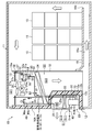
- FIG. 1 is a perspective view of the container refrigeration apparatus according to Embodiment 1 as viewed from the outside of the warehouse.
- FIG. 2 is a side cross-sectional view illustrating a schematic configuration of the container refrigeration apparatus according to the first embodiment.
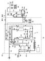
- FIG. 3 is a piping diagram illustrating the configuration of the refrigerant circuit of the container refrigeration apparatus according to the first embodiment.
- FIG. 4 is a piping system diagram showing the configuration of the CA device of the container refrigeration apparatus of the first embodiment, and shows the air flow in the first distribution state.
- FIG. 5 is a piping system diagram showing the configuration of the CA device of the container refrigeration apparatus of the first embodiment, and shows the air flow in the second distribution state.
- FIG. 1 is a perspective view of the container refrigeration apparatus according to Embodiment 1 as viewed from the outside of the warehouse.
- FIG. 2 is a side cross-sectional view illustrating a schematic configuration of the container refrigeration apparatus according to the first embodiment.
- FIG. 3 is a piping diagram illustrating the configuration of the
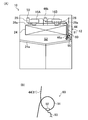
- FIG. 6A is a side view of the container refrigeration apparatus according to Embodiment 1 as viewed from the outside, and FIG. 6B is a partially enlarged view of FIG.
- FIG. 7A is a side view of the container refrigeration apparatus according to Embodiment 1 as viewed from the inside of the box, and FIG. 7B is a partially enlarged view of FIG. 7A.
- FIG. 8 is a diagram illustrating a mode transition state in the normal control according to the first embodiment.
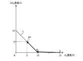
- FIG. 9 is a graph showing a change in the composition of the container air in the container in the concentration adjustment operation in the container refrigeration apparatus of the first embodiment.
- FIG. 10 is a piping diagram illustrating the configuration of the CA device of the container refrigeration apparatus according to the second embodiment.
- FIG. 11 is the schematic perspective view which looked at the container refrigeration apparatus of Embodiment 3 from the warehouse outer side.
- Embodiment 1 of the Invention As shown in FIG.1 and FIG.2, the container refrigeration apparatus (10) is provided in the container (11) used for marine transportation etc., and cools the internal air of this container (11). In the container (11), the plants (15) are stored in a boxed state. The plant (15) breathes by taking in oxygen (O 2 ) in the air and releasing carbon dioxide (CO 2 ). For example, fruits and vegetables such as banana and avocado, vegetables, grains, bulbs, fresh flowers, etc. It is.
- O 2 oxygen
- CO 2 carbon dioxide
- the container (11) is formed in an elongated box shape with one end face opened.
- the container refrigeration apparatus (10) includes a casing (12), a refrigerant circuit (20), and a CA apparatus (Controlled Atmosphere System) (60), and is attached so as to close the open end of the container (11). Yes.
- the casing (12) includes a warehouse outer wall (12a) located on the outside of the container (11) and a cabinet inner wall (12b) located on the inside of the container (11). .
- the outer wall (12a) and the inner wall (12b) are made of, for example, an aluminum alloy.
- the outer wall (12a) is attached to the peripheral edge of the opening of the container (11) so as to close the opening end of the container (11).
- the warehouse outer wall (12a) is formed so that the lower part bulges to the inside of the container (11).
- the inner wall (12b) is placed opposite the outer wall (12a).
- the inner wall (12b) bulges to the inner side corresponding to the lower part of the outer wall (12a).
- a heat insulating material (12c) is provided in the space between the inner wall (12b) and the outer wall (12a).
- the lower part of the casing (12) is formed so as to bulge toward the inner side of the container (11).
- an outside storage space (S1) is formed outside the container (11) at the lower part of the casing (12), and an inside storage space is provided inside the container (11) at the upper part of the casing (12). (S2) is formed.
- first and second service doors (16A, 16B) are closed by first and second service doors (16A, 16B) that can be opened and closed, respectively.
- Each of the first and second service doors (16A, 16B) is constituted by a warehouse outer wall, a warehouse inner wall, and a heat insulating material, like the casing (12).
- a partition plate (18) is arranged inside the container (11).
- This partition plate (18) is comprised by the substantially rectangular-shaped board member, and is standingly arranged in the attitude
- the partition plate (18) divides the interior of the container (11) from the interior storage space (S2).
- a suction port (18a) is formed between the upper end of the partition plate (18) and the ceiling surface in the container (11). The internal air of the container (11) is taken into the internal storage space (S2) through the suction port (18a).
- a partition wall (13) extending in the horizontal direction is provided in the storage space (S2).
- the partition wall (13) is attached to an upper end portion of the partition plate (18), and an opening in which a later-described internal fan (26) is installed is formed.
- the partition wall (13) includes an internal storage space (S2), a primary space (S21) on the suction side of the internal fan (26), and a secondary space (S22) on the outlet side of the internal fan (26).
- the storage space (S2) is vertically divided by the partition wall (13), the primary space on the suction side (S21) is on the upper side, and the secondary space on the outlet side (S22) is on the lower side. Formed on the side.
- a floor board (19) is provided with a gap between the bottom of the container (11).
- a boxed plant (15) is placed on the floor board (19).
- An underfloor channel (19a) is formed between the bottom surface in the container (11) and the floor board (19).
- a gap is provided between the lower end of the partition plate (18) and the bottom surface in the container (11), and communicates with the underfloor channel (19a).
- the refrigerant circuit (20) includes a compressor (21), a condenser (22), an expansion valve (23), and an evaporator (24) in order by a refrigerant pipe (20a). It is a closed circuit configured by connecting.
- the condenser (22) In the vicinity of the condenser (22), it is rotationally driven by an external fan motor (25a), and attracts the air outside the container (11) (outside air) into the external storage space (S1).
- An outside fan (25) to send to 22) is provided.
- the condenser (22) heat is generated between the refrigerant pressurized by the compressor (21) and flowing inside the condenser (22) and the outside air sent to the condenser (22) by the external fan (25). Exchange is performed.
- the external fan (25) is a propeller fan.
- an internal fan that is rotationally driven by an internal fan motor (26a), draws the internal air of the container (11) from the suction port (18a), and blows it out to the evaporator (24)
- Two (26) are provided.
- the pressure is reduced by the expansion valve (23) and flows between the refrigerant flowing in the evaporator (24) and the internal air sent to the evaporator (24) by the internal fan (26). Heat exchange takes place.
- the internal fan (26) has a propeller fan (rotary blade) (27a), a plurality of stationary blades (27b), and a fan housing (27c).
- the propeller fan (27a) is connected to the internal fan motor (26a), is driven to rotate around the rotation axis by the internal fan motor (26a), and blows air in the axial direction.
- the plurality of stationary blades (27b) are provided on the blowing side of the propeller fan (27a), and rectify the air flow blown and swirled from the propeller fan (27a).
- the fan housing (27c) is configured by a cylindrical member having a plurality of stationary blades (27b) attached to the inner peripheral surface, extends to the outer periphery of the propeller fan (27a), and surrounds the outer periphery of the propeller fan (27a).
- the condenser (22) includes a lower first space (S11) and an upper second space (S12) at the central portion in the vertical direction of the external storage space (S1). It is provided to partition.
- the condenser (22) is a so-called fin-and-tube type air heat exchanger, and is provided so that air flows between the lower first space (S11) and the upper second space (S12). It has been.
- the first space (S11) includes the compressor (21), an inverter box (29) containing a drive circuit for driving the compressor (21) at a variable speed, and a CA device (60). And a gas supply device (30).
- an external fan (25) and an electrical component box (17) are provided in the second space (S12).
- the first space (S11) is open to the outside of the container (11), while the second space (S12) is stored so that only the outlet of the outside fan (25) opens to the outside.
- the front surface between the outside (the front surface in FIG. 1) is closed by a plate-like member.
- the evaporator (24) is stored in the secondary space (S22) of the storage space (S2).
- Two internal fans (26) are provided above the evaporator (24) in the internal storage space (S2) in the width direction of the casing (12).
- the CA device (60) includes a gas supply device (30), an exhaust unit (46), a sensor unit (50), a measurement unit (80), and a control unit (55). And adjusting the oxygen concentration and carbon dioxide concentration of the air inside the container (11). Note that “concentration” used in the following description refers to “volume concentration”.
- the gas supply device (30) is a device that generates nitrogen-enriched air having a low oxygen concentration to be supplied into the container (11).
- the gas supply device (30) is configured by VPSA (Vacuum Pressure Swing Adsorption).
- the gas supply apparatus (30) is arrange
- the gas supply device (30) includes an air pump (31), a first directional control valve (32) and a second directional control valve (33), and adsorption for adsorbing nitrogen in the air.
- the gas supply device (30) is configured as one unit by housing the components in the unit case (70), and can be retrofitted to the container refrigeration device (10). Has been.
- the air pump (31) is provided in the unit case (70), and has a first pump mechanism (31a) and a second pump mechanism (31b) that suck, pressurize, and discharge air, respectively.
- the first pump mechanism (31a) and the second pump mechanism (31b) are connected to the drive shaft of the motor (41), and are driven to rotate by the motor (41), thereby sucking, pressurizing and discharging air, respectively. To do.
- the suction port of the first pump mechanism (31a) opens in the unit case (70), and the air inlet (75) of the unit case is provided with a membrane filter (76) having air permeability and waterproofness. Yes. Therefore, the first pump mechanism (31a) removes the outside air from which moisture has been removed when flowing from outside the unit case (70) through the membrane filter (76) provided at the air inlet (75). Inhale and pressurize.
- one end of the discharge passage (42) is connected to the discharge port of the first pump mechanism (31a).
- the other end of the discharge passage (42) branches into two on the downstream side and is connected to the first directional control valve (32) and the second directional control valve (33), respectively.
- the suction passage (43) is connected to the suction port of the second pump mechanism (31b).
- the other end of the suction passage (43) is divided into two on the upstream side, and is connected to each of the first directional control valve (32) and the second directional control valve (33).
- one end of the supply passage (44) is connected to the discharge port of the second pump mechanism (31b).
- the other end of the supply passage (44) opens in the primary space (S21) on the suction side of the internal fan (26) in the internal storage space (S2) of the container (11).
- the supply passage (44) is configured by a flexible tube (hereinafter referred to as supply tube (44)).
- the first pump mechanism (31a) and the second pump mechanism (31b) of the air pump (31) are oilless pumps that do not use lubricating oil. Specifically, when oil is used in the pump of the first pump mechanism (31a), when pressurized air is supplied to the first adsorption cylinder (34) and the second adsorption cylinder (35) and pressurized. Then, the oil contained in the pressurized air is adsorbed by the adsorbent, and the adsorbent adsorption performance deteriorates.
- the oil when oil is used in the pump of the second pump mechanism (31b), the oil is contained in the container (with nitrogen-concentrated air containing nitrogen desorbed from the first adsorption cylinder (34) and the second adsorption cylinder (35)). 11) will be supplied to the warehouse. That is, in this case, nitrogen-enriched air with an oily odor is supplied to the inside of the container (11) in which the plant (15) is loaded.
- the first pump mechanism (31a) and the second pump mechanism (31b) of the air pump (31) are configured by oilless pumps so that the above-described problems can be solved.
- Two air blow fans (48) for cooling the air pump (31) by blowing air toward the air pump (31) are provided on the side of the air pump (31).
- the first directional control valve (32) and the second directional control valve (33) are provided between the air pump (31) and the first adsorption cylinder (34) and the second adsorption cylinder (35) in the air circuit (3).
- the connection state between the air pump (31) and the first suction cylinder (34) and the second suction cylinder (35) is switched between the first connection state and the second connection state. This switching operation is controlled by the control unit (55).
- the first directional control valve (32) includes a discharge passage (42) connected to the discharge port of the first pump mechanism (31a) and a suction port connected to the suction port of the second pump mechanism (31b). It connects to a channel
- the first direction control valve (32) communicates the first adsorption cylinder (34) with the discharge port of the first pump mechanism (31a) and shuts it from the suction port of the second pump mechanism (31b) ( 4) and the second state in which the first adsorption cylinder (34) is communicated with the suction port of the second pump mechanism (31b) and is blocked from the discharge port of the first pump mechanism (31a).
- the second direction control valve (33) includes a discharge passage (42) connected to the discharge port of the first pump mechanism (31a) and a suction passage (43) connected to the suction port of the second pump mechanism (31b). And the top of the second suction cylinder (35).
- the second direction control valve (33) communicates the second adsorption cylinder (35) with the suction port of the second pump mechanism (31b) and shuts it from the discharge port of the first pump mechanism (31a) ( 4) and a second state in which the second adsorption cylinder (35) is communicated with the discharge port of the first pump mechanism (31a) and blocked from the suction port of the second pump mechanism (31b).
- the air circuit (3) causes the discharge port of the first pump mechanism (31a) and the first adsorption cylinder (34).
- the suction port of the second pump mechanism (31b) and the second suction cylinder (35) are switched to the first connection state.
- the first adsorption cylinder (34) performs an adsorption operation for adsorbing nitrogen in the outside air on the adsorbent
- the second adsorption cylinder (35) performs a desorption operation for desorbing nitrogen adsorbed on the adsorbent. Is called.
- both the first directional control valve (32) and the second directional control valve (33) are set to the second state
- the air circuit (3) is connected to the discharge port of the first pump mechanism (31a) and the second adsorption cylinder. (35) is connected and the suction port of the second pump mechanism (31b) and the first suction cylinder (34) are switched to the second connection state.
- the adsorption operation is performed by the second adsorption cylinder (35)
- the desorption operation is performed by the first adsorption cylinder (34).
- the first adsorbing cylinder (34) and the second adsorbing cylinder (35) are cylindrical members filled with an adsorbent inside, and in an upright posture (that is, an posture in which the respective axial directions are vertical directions). is set up.
- the adsorbent filled in the first adsorption cylinder (34) and the second adsorption cylinder (35) has a property of adsorbing nitrogen under pressure and desorbing the adsorbed nitrogen under reduced pressure.
- the adsorbent filled in the first adsorption cylinder (34) and the second adsorption cylinder (35) is, for example, smaller than the molecular diameter of nitrogen molecules (3.0 angstroms) and the molecular diameter of oxygen molecules (2.8 angstroms). ) And a porous zeolite having pores with a larger pore diameter than the above. If the adsorbent is composed of zeolite having such a pore size, nitrogen in the air can be adsorbed.
- the zeolite since the electric field is present in the pores of the zeolite due to the presence of cations and the polarity is generated, the zeolite has the property of adsorbing polar molecules such as water molecules. Therefore, not only nitrogen in the air but also moisture (water vapor) in the air is adsorbed to the adsorbent made of zeolite filled in the first adsorption cylinder (34) and the second adsorption cylinder (35). The moisture adsorbed on the adsorbent is desorbed from the adsorbent together with nitrogen by the desorption operation. Therefore, nitrogen-concentrated air containing moisture is supplied into the container (11), and the humidity inside the container can be increased. Furthermore, since the adsorbent is regenerated, the life of the adsorbent can be extended.
- adsorbing polar molecules such as water molecules. Therefore, not only nitrogen in the air but also moisture (water vapor) in the air is adsorbed to the adsorbent made of ze
- the first adsorption cylinder (34) and the second adsorption cylinder (35) are provided at the lower ends of the first adsorption cylinder (34) and the second adsorption cylinder (35) (the outlet for pressurization and the inlet for decompression).
- One end of an oxygen discharge passage (45) for guiding oxygen-enriched air generated by supplying the external air pressurized by the first pump mechanism (31a) to the outside of the container (11) is connected. Yes.
- One end of the oxygen discharge passage (45) is divided into two and is connected to each of the lower end portions of the first adsorption cylinder (34) and the second adsorption cylinder (35).
- the other end of the oxygen discharge passage (45) is opened outside the gas supply device (30), that is, outside the container (11).
- connection passage connected to the lower end portion of the first adsorption cylinder (34) allows the backflow of air from the oxygen discharge passage (45) to the first adsorption cylinder (34).
- a first check valve (37) is provided to prevent this.
- connection passage connected to the lower end of the second adsorption cylinder (35) has an air flow from the oxygen discharge passage (45) to the second adsorption cylinder (35).
- a second check valve (38) is provided for preventing backflow.
- the two connection passages constituting one end of the oxygen discharge passage (45) are connected via a purge valve (36), and an orifice (62) is provided between the purge valve (36) and each connection passage. Is provided.
- the purge valve (36) concentrates a predetermined amount of oxygen from the pressure-side adsorption cylinder (first adsorption cylinder (34) in FIG. 4) to the pressure-reduction side adsorption cylinder (second adsorption cylinder (35) in FIG. 4). It is used for guiding air and assisting in releasing nitrogen from the adsorbent of the adsorption cylinder (35, 34) on the decompression side.
- the opening / closing operation of the purge valve (36) is controlled by the control unit (55).
- An oxygen tank (39) is provided in the middle of the oxygen discharge passage (45). Between the oxygen tank (39) and the first check valve (37) and the second check valve (38). Is provided with an orifice (61).
- the oxygen tank (39) temporarily stores oxygen-enriched air generated by the first adsorption cylinder (34) and the second adsorption cylinder (35).
- the oxygen-enriched air produced in the first adsorption cylinder (34) and the second adsorption cylinder (35) is temporarily stored in the oxygen tank (39) after being depressurized by the orifice (61).
- a first adsorption cylinder (31a) is provided between the orifice (61) of the oxygen discharge passage (45) and the first check valve (37) and the second check valve (38) by the first pump mechanism (31a). 34) and a pressure sensor (49) for measuring the pressure of the pressurized air supplied to the second adsorption cylinder (35) is connected.
- the air circuit (3) indicates the air circulation state in the air circuit (3), the nitrogen enriched air generated in the first adsorption cylinder (34) and the second adsorption cylinder (35), and the air pump (31).
- the second distribution state in which the air is supplied to the container (11) by the air pump (31), and the second circulation state is supplied to the container (11) by the air pump (31).
- a distribution switching mechanism (65) for switching to a distribution state is provided.
- the flow switching mechanism (65) includes a connection passage (66), a first on-off valve (67), and a second on-off valve (68).
- the connection passage (66) is a passage for connecting the supply passage (44) to the outside portion of the container (11) of the oxygen tank (39) of the oxygen discharge passage (45).
- the first on-off valve (67) is provided on the outer side of the container (11) than the connection portion of the connection passage (66) in the oxygen discharge passage (45), and opens and closes the oxygen discharge passage (45).
- (68) is provided in the connection passage (66).
- the first on-off valve (67) and the second on-off valve (68) are open / close controlled by the control unit (55).
- Air flow state in the air circuit (3) by operating the air pump (31) with the control unit (55) closing the first on-off valve (67) and opening the second on-off valve (68) Is switched to the first distribution state (the state shown in FIG. 4).
- the controller (55) opens the first on-off valve (67) and closes the second on-off valve (68) to operate the air pump (31), thereby The distribution state is switched to the second distribution state (the state shown in FIG. 5).
- the nitrogen-enriched air and the oxygen-enriched air generated in the first adsorption cylinder (34) and the second adsorption cylinder (35) are combined to generate air having the same composition as the outside air, and the air is supplied into the container (11).
- the control unit (55) switches both the first directional control valve (32) and the second directional control valve (33) to the first state shown in FIG.
- the air circuit (3) is configured such that the first adsorption cylinder (34) communicates with the discharge port of the first pump mechanism (31a) and is blocked from the suction port of the second pump mechanism (31b), and the second adsorption The cylinder (35) communicates with the suction port of the second pump mechanism (31b) and enters the first connection state where the cylinder (35) is blocked from the discharge port of the first pump mechanism (31a).
- the first pump mechanism (31a) supplies pressurized outside air to the first adsorption cylinder (34). Nitrogen contained in the air flowing into the first adsorption cylinder (34) is adsorbed by the adsorbent in the first adsorption cylinder (34). Thus, during the first operation, in the first adsorption cylinder (34), the pressurized outside air is supplied from the first pump mechanism (31a), and the nitrogen in the outside air is adsorbed by the adsorbent. Oxygen-enriched air in which the nitrogen concentration is lower than the outside air and the oxygen concentration is higher than the outside air is generated. The oxygen-enriched air flows out from the first adsorption cylinder (34) to the oxygen discharge passage (45).
- the second pump mechanism (31b) sucks air from the second adsorption cylinder (35).
- nitrogen adsorbed on the adsorbent of the second adsorption cylinder (35) is sucked together with air by the second pump mechanism (31b) and desorbed from the adsorbent.
- the second adsorption cylinder (35) is desorbed from the adsorbent by the internal air being sucked by the second pump mechanism (31b) and the nitrogen adsorbed on the adsorbent being desorbed.
- Nitrogen-enriched air containing nitrogen and having a higher nitrogen concentration than the outside air and a lower oxygen concentration than the outside air is generated. The nitrogen-enriched air is sucked into the second pump mechanism (31b), pressurized, and then discharged to the supply passage (44).
- both the first directional control valve (32) and the second directional control valve (33) are switched to the second state opposite to the state shown in FIG. 4 by the control unit (55).
- the air circuit (3) is configured such that the first adsorption cylinder (34) communicates with the suction port of the second pump mechanism (31b) and is blocked from the discharge port of the first pump mechanism (31a), and the second adsorption The cylinder (35) communicates with the discharge port of the first pump mechanism (31a) and enters the second connection state where it is blocked from the suction port of the second pump mechanism (31b).
- the first pump mechanism (31a) supplies pressurized outside air to the second adsorption cylinder (35). Nitrogen contained in the air flowing into the second adsorption cylinder (35) is adsorbed by the adsorbent of the second adsorption cylinder (35).
- pressurized external air is supplied from the first pump mechanism (31a), and nitrogen in the external air is adsorbed by the adsorbent, Oxygen-enriched air in which the nitrogen concentration is lower than the outside air and the oxygen concentration is higher than the outside air is generated.
- the oxygen-enriched air flows out from the second adsorption cylinder (35) to the oxygen discharge passage (45).
- the second pump mechanism (31b) sucks air from the first adsorption cylinder (34).
- nitrogen adsorbed on the adsorbent of the first adsorption cylinder (34) is sucked together with air by the second pump mechanism (31b) and desorbed from the adsorbent.
- the first adsorption cylinder (34) is desorbed from the adsorbent by the internal air sucked by the second pump mechanism (31b) and the nitrogen adsorbed on the adsorbent is desorbed.
- Nitrogen-enriched air containing nitrogen and having a higher nitrogen concentration than the outside air and a lower oxygen concentration than the outside air is generated. The nitrogen-enriched air is sucked into the second pump mechanism (31b), pressurized, and then discharged to the supply passage (44).
- nitrogen enriched air and oxygen enriched air are generated in the air circuit (3) by alternately repeating the first operation and the second operation.
- the flow state of the air in the air circuit (3) is switched between the first flow state and the second flow state by the flow switching mechanism (65).
- the air circuit (3) is operated by operating the air pump (31) with the first opening / closing valve (67) closed and the second opening / closing valve (68) opened by the control unit (55). Is switched to the first distribution state shown in FIG. In the first flow state, as in the conventional gas supply device (30), the oxygen-enriched air generated in the first adsorption cylinder (34) and the second adsorption cylinder (35) is the first of the air pump (31).
- the concentrated air is supplied into the container (11) through the supply passage (44) by the pressurizing force of the second pump mechanism (31b) of the air pump (31).
- the nitrogen-enriched air generated in the first adsorption cylinder (34) and the second adsorption cylinder (35) is caused by the applied pressure of the second pump mechanism (31b) of the air pump (31). Gas supply operation to supply the container (11) is performed.
- the controller (55) opens the first on-off valve (67) and closes the second on-off valve (68) to operate the air pump (31), thereby
- the distribution state is switched to the second distribution state shown in FIG.
- the first adsorption cylinder (34) and the second adsorption cylinder (35) and the outside of the gas supply device (30) (outside the chamber) are blocked, while the oxygen discharge passage (45) and the supply are supplied.
- the passage (44) is connected to the passage (66).
- the oxygen-enriched air generated in the first adsorption cylinder (34) and the second adsorption cylinder (35) is supplied to the oxygen discharge passage (45) by the applied pressure of the first pump mechanism (31a) of the air pump (31). Is pushed into the supply passage (44) through the connection passage (66). In the supply passage (44), the nitrogen-enriched air generated in the first adsorption cylinder (34) and the second adsorption cylinder (35) by the pressure of the second pump mechanism (31b) of the air pump (31) is stored in the container. It flows toward the inside of (11).
- the oxygen-enriched air merges with the flow of nitrogen-enriched air, and air having the same composition as the outside air is generated.
- the air having the same composition as the outside air generated in the supply passage (44) in this way is supplied into the container (11) by the pressurizing force of the second pump mechanism (31b) of the air pump (31).
- the air having the same composition as the outside air in the air circuit (3) is converted into the inside of the container (11) by the pressurizing force of the second pump mechanism (31b) of the air pump (31).
- the outside air introduction operation is performed.
- the exhaust part (46) has an exhaust passage connecting the storage space (S2) in the warehouse and the outside of the warehouse, and an exhaust valve (46b) connected to the exhaust passage (46a). ing.
- the exhaust passage (46a) is constituted by a flexible tube (hereinafter referred to as an exhaust tube (46a)).
- the exhaust tube (46a) is inserted into a through-hole (12d) that connects the storage space (S2) formed in the casing (12) and the second space (S12) of the storage space (S1) outside the storage, It penetrates the casing (12).
- the exhaust tube (46a) has an inlet end opened in the secondary space (S22) on the outlet side of the internal fan (26), and an outlet end in the second space (S12) of the external storage space (S1). It is open. More specifically, the outlet end of the exhaust tube (46a) opens in the second space (S12) in the vicinity of the motor (25a) disposed on the suction side of the external fan (25) made of a propeller fan. It is provided to do.
- the second space (S12) is closed so that only the outlet of the outside fan (25) opens to the outside.
- the second space (S12) becomes a suction side space into which air is sucked by the external fan (25).
- the outlet end of the exhaust tube (46a) is provided in the space on the suction side of the external fan (25).
- the exhaust valve (46b) is provided on the inner side of the exhaust tube (46a), and allows the air to flow in the exhaust tube (46a) and the air flow in the exhaust tube (46a). It is comprised by the solenoid valve which switches to the closed state which interrupts
- the opening / closing operation of the exhaust valve (46b) is controlled by the control unit (55).
- the exhaust unit (46) opens the exhaust valve (46b) by the control unit (55) during the operation of the external fan (25), thereby allowing the internal storage space (S2) ) (Exhaust air) is exhausted to the outside.
- the pressure in the second space (S12) on the suction side of the outside fan (25) becomes lower than the pressure (atmospheric pressure) in the outside space.
- the pressure drop of the pressure in the second space (S12) on the suction side of the outside fan (25) becomes larger.
- the pressure inside the container (11) may be lower than the pressure (atmospheric pressure) in the outside space.
- the air volume of the external fan (25) the pressure in the secondary space (S22) on the outlet side of the internal fan (26) where the inlet end of the exhaust tube (46a) is easily opened can be reduced. It can be made higher than the pressure (atmospheric pressure) in the external space where the outlet end of the exhaust tube (46a) opens.
- the sensor unit (50) is provided in the secondary space (S22) on the outlet side of the internal fan (26) in the internal storage space (S2).
- the sensor unit (50) includes an oxygen sensor (51), a carbon dioxide sensor (52), a fixed plate (53), a membrane filter (54), a connecting pipe (56), and an exhaust pipe (57).
- the oxygen sensor (51) has an oxygen sensor box (51a) in which a galvanic cell type sensor is accommodated.
- the oxygen sensor (51) measures the oxygen concentration in the gas in the oxygen sensor box (51a) by measuring the value of the current flowing through the electrolyte solution of the galvanic cell type sensor.
- the outer surface of the oxygen sensor box (51a) is fixed to the fixed plate (53).
- An opening is formed in the outer surface of the oxygen sensor box (51a) opposite to the surface fixed to the fixing plate (53), and a membrane filter (54) having air permeability and waterproofness is formed in the opening. ) Is attached.
- a branch pipe (81) of a measurement unit (80) described later is connected to the lower surface of the oxygen sensor box (51a) via a connector (pipe joint).
- one end of the connecting pipe (56) is connected to one side surface of the oxygen sensor box (51a) via a connector.
- the carbon dioxide sensor (52) has a carbon dioxide sensor box (52a), radiates infrared rays to the gas in the carbon dioxide sensor box (52a), and measures the absorption amount of infrared rays having a wavelength specific to carbon dioxide. Is a non-dispersive infrared (NDIR) sensor that measures the concentration of carbon dioxide in a gas.
- the other end of the connecting pipe (56) is connected to one side surface of the carbon dioxide sensor box (52a) via a connector.
- One end of the exhaust pipe (57) is connected to the other side surface of the carbon dioxide sensor box (52a) via a connector.
- the fixing plate (53) is fixed to the casing (12) with the oxygen sensor (51) and the carbon dioxide sensor (52) attached.
- the communication pipe (56) is connected to the side surface of the oxygen sensor box (51a) and the side surface of the carbon dioxide sensor box (52a), and the internal space of the oxygen sensor box (51a) and the carbon dioxide sensor box ( It communicates with the internal space of 52a).
- one end of the exhaust pipe (57) is connected to the other side surface of the carbon dioxide sensor box (52a), and the other end is opened in the vicinity of the suction port of the internal fan (26). That is, the exhaust pipe (57) communicates the internal space of the carbon dioxide sensor box (52a) with the primary space (S21) of the storage space (S2).
- the secondary space (S22) and the primary space (S21) of the storage space (S2) are the membrane filter (54), the internal space of the oxygen sensor box (51a), the connecting pipe (56), The carbon dioxide sensor box (52a) communicates with the internal space and the air passage (58) formed by the exhaust pipe (57). Therefore, during operation of the internal fan (26), the pressure in the primary space (S21) becomes lower than the pressure in the secondary space (S22).
- the air passage (58) connected to the carbon sensor (52) the in-compartment air flows from the secondary space (S22) side to the primary space (S21) side. In this way, the internal air passes through the oxygen sensor (51) and the carbon dioxide sensor (52) in order, the oxygen concentration of the internal air is measured by the oxygen sensor (51), and the carbon dioxide sensor (52) The carbon dioxide concentration of the internal air is measured.
- the measurement unit (80) includes a branch pipe (81) and a measurement on-off valve (82), and branches part of the nitrogen-enriched air generated in the gas supply device (30) and flowing through the supply passage (44). And led to the oxygen sensor (51).
- the branch pipe (81) has one end connected to the supply passage (44) and the other end connected to the oxygen sensor box (51a) of the oxygen sensor (51). With such a configuration, the branch pipe (81) makes the supply passage (44) communicate with the internal space of the oxygen sensor box (51a).
- the branch pipe (81) is provided so as to branch from the supply passage (44) in the unit case (70) and extend inside and outside the unit case.
- the branch pipe (81) is configured by a flexible tube (hereinafter referred to as a measurement tube (81)).
- the measurement on-off valve (82) is provided inside the unit case of the branch pipe (81).
- the on-off valve for measurement (82) is an electromagnetic valve that switches between an open state allowing the flow of nitrogen-enriched air in the branch pipe (81) and a closed state blocking the flow of the nitrogen-enriched air in the branch pipe (81). It is configured.
- the opening / closing operation of the measurement on-off valve (82) is controlled by the control unit (55). Although details will be described later, the measurement on-off valve (82) is opened only when an air supply measurement operation described later is executed, and is closed in other modes.
- the control unit (55) is configured to execute a concentration adjustment operation for setting the oxygen concentration and the carbon dioxide concentration of the air inside the container (11) to desired concentrations. Specifically, the control unit (55) determines the composition (oxygen concentration and carbon dioxide concentration) of the air in the container (11) based on the measurement results of the oxygen sensor (51) and the carbon dioxide sensor (52). The operations of the gas supply device (30) and the exhaust unit (46) are controlled so as to obtain a desired composition (for example, oxygen concentration 5%, carbon dioxide concentration 5%). As shown in FIG. 8, in the present embodiment, the control unit (55) is configured to perform the concentration adjustment operation by executing the start-up control and the normal control. The control unit (55) performs normal control after completion of predetermined start-up control, and is configured to perform an oxygen concentration reduction mode and an air composition adjustment mode in the normal control.
- control unit (55) controls the operation of the measurement on-off valve (82) in accordance with a command from the user or periodically, and controls the oxygen concentration of the nitrogen-enriched air generated in the gas supply device (30). It is configured to perform an air supply measurement operation to measure.
- control unit (55) controls the operations of the air pump (31), the first on-off valve (67), and the second on-off valve (68) in accordance with a command from the user or periodically, so that the container (11)
- the supply tube (44), the measurement tube (81) and the exhaust tube (46a) are formed in the casing (12). It is inserted through the through-hole (12d), and is provided across the interior and exterior of the casing (12).
- the supply tube (44) and the measurement tube (81) are also inserted through the through hole (12d) of the casing (12) and penetrate the casing (12), like the exhaust tube (46a).
- Each of the supply tube (44) and the measurement tube (81) has an inlet end connected to the air circuit (3) of the gas supply device (30) and an outlet end connected to the secondary space (S2) in the storage space (S2). Open in S22).
- Each has a drainage structure (90) for discharging the wastewater.
- the drainage structure (90) provided in the three tubes (44, 81, 46a) includes a trap portion (91), a pipe joint (92), and And a drain tube (93).
- the trap portion (91) is formed by bending a portion of each flexible tube (44, 81, 46a) in an annular shape and bundling the portion where the tubes (44, 81, 46a) overlap with a binding band or the like. ing.
- the pipe joint (92) is attached to a part other than the binding part of the trap part (91).
- One end of the drain tube (93) is connected to the pipe joint (92), and the other end (not shown) is opened outside the casing (12).
- each tube (44, 81, 46a) By arranging the drainage structure (90) having such a configuration so that the pipe joint (92) is positioned at the lowermost side in the trap portion (91), the inside of each tube (44, 81, 46a) When the generated dew condensation water flows through the trap part (91) together with air, it is collected near the pipe joint (92) located at the lowermost side of the trap part (91) by gravity, and passes through the drain tube (93). It is discharged outside the casing (12).
- the exhaust tube (46a) is provided with a drainage structure (90) in the outside portion disposed in the outside storage space (S1).
- the drainage structure (90) is located near the through hole (12d) that communicates the inside and outside of the casing (12) in the outside portion of the exhaust tube (46a). It is formed at the position immediately after exiting from the hole (12d) to the outside of the warehouse.
- the dew condensation water generated inside the exhaust tube (46a) can be captured near the location where the dew condensation water is generated and discharged to the outside. Further, as shown in FIG. 6A, the outside portion of the exhaust tube (46a) descends from the trap portion (91) toward the outlet end opened on the suction side of the outside fan (25). It is arranged. Therefore, even when seawater reaches near the outlet end of the exhaust tube (46a), it does not flow into the cabinet through the exhaust tube (46a) against gravity.
- each tube (44,81) is provided with the drainage structure (90) in the interior part arrange
- the drainage structure (90) is located near the through hole (12d) that communicates the inside of the casing (12) and the outside of the casing (12) in the inside portion of each tube (44,81) (in this embodiment, It is formed at the position immediately after entering the inside of the warehouse from the through hole (12d).
- the outlet end of each tube (44, 81) is provided in the secondary space (S22) so as to open on the upper surface of the drain pan (24a) that receives the dew condensation water generated in the evaporator (24).
- a cooling operation for cooling the internal air of the container (11) is executed by the unit controller (100) shown in FIG.
- the operation of the compressor (21), the expansion valve (23), the external fan (25), and the internal fan (26) is performed based on the measurement result of a temperature sensor (not shown) by the unit controller (100).
- the temperature of the internal air is controlled to a desired target temperature.
- the refrigerant circuit (20) the refrigerant circulates to perform a vapor compression refrigeration cycle.
- the internal air of the container (11) guided to the internal storage space (S2) by the internal fan (26) flows through the evaporator (24) when passing through the evaporator (24). Cooled by the refrigerant.
- the in-compartment air cooled in the evaporator (24) is blown out again from the outlet (18b) into the container (11) through the underfloor channel (19a). Thereby, the internal air of the container (11) is cooled.
- the CA (60) causes the controller (55) shown in FIG. 4 to store the container (11) based on the measurement results of the oxygen sensor (51) and the carbon dioxide sensor (52).
- a concentration adjustment operation is performed to adjust the composition of the internal air (oxygen concentration and carbon dioxide concentration) to a desired composition (for example, oxygen concentration 5%, carbon dioxide concentration 5%).
- the control unit (55) performs the concentration adjustment operation by executing the start-up control and the normal control. Further, in the normal control, the control unit (55) executes the oxygen concentration reduction mode and the air composition adjustment mode to change the oxygen concentration and carbon dioxide concentration of the air in the container (11) to a predetermined target concentration SP. Adjust to.
- the control unit (55) controls the measurement on-off valve (82) to be closed.
- the control unit (55) communicates with the unit control unit (100), and the unit control unit (100) rotates the internal fan (26). Accordingly, the internal air is supplied to the oxygen sensor (51) and the carbon dioxide sensor (52) by the internal fan (26), and the oxygen concentration and the carbon dioxide concentration of the internal air are measured. .
- the control unit (55) executes the oxygen concentration reduction mode in the normal control after the start-up control is completed.
- the control unit (55) The lowering mode is terminated and the air composition adjustment mode is executed.
- the oxygen concentration of the air in the container (11) measured by the oxygen sensor (51) is set to a target oxygen concentration SPO 2 (5% in this embodiment) and a predetermined concentration V (in this embodiment). , 1.0%) or more (6.0% in this embodiment), the control unit (55) ends the air composition adjustment mode and returns to the oxygen concentration reduction mode.
- the oxygen concentration reduction mode and the air composition adjustment mode in the normal control will be described in detail.
- the control unit (55) switches the air circuit (3) to the first flow state, and in the air circuit (3), nitrogen-concentrated air (nitrogen concentration 90%, oxygen concentration 10%) is supplied.
- chamber of a container (11) is performed.
- the control unit (55) controls the exhaust valve (46b) of the exhaust unit (46) to open to perform an exhaust operation, and nitrogen enriched air is brought into the container (11) by the gas supply operation.
- the air in the cabinet is discharged to the outside as much as the supplied amount. With such a gas supply operation and an exhaust operation, the air in the warehouse is replaced with nitrogen-enriched air, so that the oxygen concentration of the air in the warehouse decreases (point A ⁇ point B in FIG. 9).
- Control unit (55) becomes the target density sum total value is the sum of the target oxygen concentration SPO 2 and the target carbon dioxide concentration SPCO 2 which is the sum of oxygen and carbon dioxide concentrations in the air inside the container (11) (Up to point B in FIG. 9), the gas supply operation and the exhaust operation are stopped.
- the oxygen concentration decreases and the carbon dioxide concentration increases. That is, by stopping the gas supply operation and the exhaust operation at an arbitrary point on the straight line L, thereafter, the composition of the air in the container (11) can be targeted only by using the respiration of the plant (15). It can be adjusted to the composition.
- the control unit (55) ends the oxygen concentration reduction mode and starts the air composition adjustment mode.
- the control unit (55) has a predetermined concentration X (0.5% in the present embodiment) where the oxygen concentration of the internal air is higher than the target oxygen concentration SPO 2 (5% in the present embodiment). If the lower limit value (4.5% in the present embodiment) is lower than the lower limit value, oxygen concentration increase control is performed to increase the oxygen concentration of the internal air.
- the control unit (55) switches the air circuit (3) to the second flow state, and air (nitrogen-enriched air and oxygen-enriched air having the same composition as the outside air in the air circuit (3) is used.
- air nitrogen-enriched air and oxygen-enriched air having the same composition as the outside air in the air circuit (3) is used.
- the outside air introduction operation for supplying the air generated by mixing) into the container (11) is performed.
- the control unit (55) controls the exhaust valve (46b) of the exhaust unit (46) to be in an open state to perform an exhaust operation.
- the air in the cabinet is exhausted to the outside by the amount supplied into the cabinet.
- the control unit (55) has a value (this embodiment) in which the oxygen concentration of the internal air is higher by a predetermined concentration X (0.5% in this embodiment) than the target oxygen concentration SPO 2 (5% in this embodiment). In the embodiment, when it becomes 5.5%) or more, the outside air introduction operation and the exhaust operation are stopped, and the oxygen concentration increase control is ended.
- the control unit (55) is configured such that the carbon dioxide concentration of the internal air is a predetermined concentration Y (0 in the present embodiment) than the target carbon dioxide concentration SPCO 2 (5% in the present embodiment). .5%) higher than the upper limit (5.5% in this embodiment) or more, the carbon dioxide concentration lowering control is performed to reduce the carbon dioxide concentration of the air in the warehouse.
- the control unit (55) switches the air circuit (3) to the first flow state, and in the air circuit (3), nitrogen concentrated air (nitrogen concentration 90). %, Oxygen concentration 10%) is generated and supplied into the container (11).
- the control unit (55) controls the exhaust valve (46b) of the exhaust unit (46) to open to perform an exhaust operation, and nitrogen enriched air is brought into the container (11) by the gas supply operation.
- the air in the cabinet is discharged to the outside as much as the supplied amount. By such gas supply operation and exhaust operation, the internal air is replaced with nitrogen-enriched air, so that the carbon dioxide concentration in the internal air of the container (11) is lowered.
- the control unit (55) has a value in which the carbon dioxide concentration of the internal air is lower by a predetermined concentration Y (0.5% in this embodiment) than the target carbon dioxide concentration SPCO 2 (5% in this embodiment). When it is less than 4.5% in this embodiment, the gas supply operation and the exhaust operation are stopped, and the carbon dioxide concentration reduction control is terminated.
- the air circuit (3) is switched to the second flow state, and the air circuit (3) has the same composition as the outside air (nitrogen-enriched air and oxygen-enriched air).
- the outside air may be introduced into the container (11) and supplied to the inside of the container (11).
- a control part (55) performs the air supply measurement operation
- the air supply measurement operation is performed in parallel when the internal fan (26) stops during the gas supply operation such as the above-described concentration adjustment operation or trial operation.
- the composition (oxygen concentration, nitrogen concentration) of the nitrogen-enriched air generated in the gas supply device (30) is desired by measuring the oxygen concentration of the nitrogen-enriched air generated in the gas supply device (30). (For example, nitrogen concentration 90%, oxygen concentration 10%) can be confirmed.
- the outer end of the exhaust tube (exhaust passage) (46a) is opened on the suction side of the external fan (25) in the external storage space (S1). I was allowed to. Therefore, the rotation of the outside fan (25) causes the suction side pressure of the outside fan (25) where the outside end of the exhaust tube (46a) opens to the inside side of the exhaust tube (46a). It can be made lower than the pressure on the outlet side of the internal fan (26) whose end is open. Therefore, even when the pressure inside the container (11) is lower than the pressure outside the container, the pressure in the space where the inner end of the exhaust tube (46a) opens by the outside fan (25) is reduced.
- all of the outside of the exhaust tube (46a) is stored in the second space (S1) in the external storage space (S1) located downstream of the condenser (22) of the outside air flow. S12).
- the internal air flowing through the exhaust tube (46a) is externally heated by the refrigerant when passing through the condenser (22) in the entire external portion of the exhaust tube (46a). Warmed by outside air. Even when the outside air temperature is extremely low, it is possible to suppress the formation of condensation over the entire outside of the exhaust tube (46a). Therefore, the dew condensation water generated inside the exhaust tube (46a) is blown out from the end together with the inside air, and is not blown to the outside fan (25) or the condenser (22). Corrosion of the external fan (25) and condenser (22) due to adhesion can be prevented.
- the exhaust tube (46a) is provided with the drainage structure (90) for discharging the dew condensation water to the outside of the chamber where dew condensation may occur inside. Therefore, the dew condensation water generated inside the exhaust tube (46a) is discharged to the outside through the drainage structure (90), so that the dew condensation water can be prevented from flowing into the warehouse.
- the drainage structure (90) includes a trap part (91) constituted by a part of the exhaust tube (46a) and a drain tube (91) connected to the trap part (91). 93).
- the drainage structure (90) is provided at a position near the through hole (12d) for the outside of the warehouse where condensation may occur inside the exhaust tube (46a). Condensed water generated inside the exhaust tube (46a) can be captured near the location where the condensed water is generated and discharged to the outside.
- Embodiment 2 of the present invention As shown in FIG. 10, the second embodiment is obtained by changing the configuration of the exhaust section (46) in the container refrigeration apparatus (10) of the first embodiment.
- the exhaust valve (46b) constituted by the electromagnetic valve in the first embodiment is constituted by a check valve which opens in the second embodiment when the pressure difference between both ends becomes a predetermined value or more.
- the exhaust valve (46b) consisting of this check valve allows only air flow from the inside to the outside of the chamber in the exhaust tube (46a) that penetrates the casing (12) from the inside to the outside. It is provided on the inner side of the exhaust tube (46a) so as to prevent circulation.
- the exhaust valve (46b) by performing the gas supply operation and the outside air introduction operation by the exhaust valve (46b) including such a check valve, the pressure inside the container (11) is reduced by the outside fan (25).
- the exhaust valve (46b) opens and the air in the container (11) opens the exhaust tube (46a). It is discharged out of the warehouse.
- the exhaust valve (46b) is not controlled by the control unit (55), and the second space (S12) inside the container (11) and outside the container (S12). It automatically opens and closes according to the pressure difference with the pressure of) to stabilize the pressure inside the container (11) to a pressure value that is higher than the pressure in the second space (S12) outside the container by a predetermined pressure value. Can be made. As a result, since the gas supply operation and the outside air introduction operation can be stabilized, the composition (oxygen concentration and carbon dioxide concentration) of the internal air of the container (11) can be easily adjusted, and can be performed with high accuracy. .
- Embodiment 3 of the present invention As shown in FIG. 11, the third embodiment is the same as the first and second embodiments, except that the condenser (22), the external fan (25), the electrical component box (17), and the inverter in the external storage space (S1). The positional relationship with the box (29) is changed.
- the condenser (22) formed so as to extend in a straight line in the horizontal direction is replaced by three heat exchange surfaces (bending positions) 22a, 22b, 22c) is changed to a condenser (22) formed into a U-shape, and this condenser (22) is placed in the upper central part of the external storage space (S1) at each heat exchange surface ( 22a, 22b, and 22c) are provided so as to be located on the upper side, the right side, and the lower side in FIG.
- the external fan (25) provided above the condenser (22) in the first and second embodiments is provided inside the U-shaped condenser (22) in the third embodiment. .
- the electrical component box (17) provided above the condenser (22) in the first and second embodiments is provided on the left side of the condenser (22) in FIG. 11 in the third embodiment.
- the inverter box (29) provided below the condenser (22) in the first and second embodiments is provided on the right side in FIG. 11 of the condenser (22) in the third embodiment.
- the outside storage space (S1) is partitioned by the condenser (22) into a first space (S11) on the upstream side of the outside air flow and a second space (S12) on the downstream side. Yes. Therefore, the outside fan (25) arranged inside the condenser (22) is provided in the second space (S12). Also in the third embodiment, the first space (S11) is opened to the outside of the container (11), while the second space (S12) has only the outlet of the outside fan (25).
- the front surface (front surface in FIG. 11) and the left side surface between the outside and the outside of the warehouse are closed by a plate-like member so as to open to the outside of the warehouse.
- the left side surface of the second space (S12) is closed by the right side surface of the electrical component box (17).
- illustration is abbreviate
- the edge part of the warehouse outer side of an exhaust passage (46a) is opened in 2nd space (S12).
- the outside fan (25) provided in the second space (S12) is open on the back side in FIG. 11 and inside the U-shaped condenser (22).
- the trap part (91) of the drainage structure (90) is formed by bending a part of each flexible tube (44, 81, 46a) in an annular shape and bundling it with a binding band or the like. It was.
- the trap part (91) may have any shape as long as the condensed water can be temporarily stored, and may be formed in, for example, a U shape or an S shape.
- the exhaust tube (46a) it is not necessary to provide all of the exhaust tube (46a) outside the warehouse in the second space (S12), at least partly May be provided in the second space (S12).
- the internal air flowing through the exhaust tube (46a) passes through the condenser (22). Since it is warmed by the outside air heated, the occurrence of condensation can be suppressed.
- one air pump (31) has the first pump mechanism (31a) and the second pump mechanism (31b).
- the first pump mechanism (31a) and the second pump mechanism (31b) ) May be constituted by two individual air pumps.
- the first adsorption unit and the second adsorption unit are configured to perform adsorption and desorption of nitrogen using one adsorption cylinder.
- the number is not limited to one.
- each suction part may be constituted by three suction cylinders, and a total of six suction cylinders may be used.
- CA the container refrigeration apparatus (10) provided in the container (11) for marine transportation
- CA concerning this invention
- the use of the device (60) is not limited to this.
- the CA device (60) according to the present invention can be used for adjusting the composition of air in a warehouse, for example, a container for land transportation, a simple refrigerated warehouse, a warehouse at room temperature, in addition to a container for sea transportation.
- the present invention is useful for a container refrigeration apparatus that cools the internal air of a container and adjusts the composition of the internal air of the container.
Abstract
This refrigeration apparatus for containers, in which an internal air conditioning device that adjusts the composition of internal air is provided, enables the discharge of internal air even when the pressure inside the container is lower than that outside the container. This refrigeration apparatus for containers includes: a casing (12) that forms an external storage space (S1) in communication with the exterior of a container (11), and an internal storage space (S2) in communication with the interior of the container (11); a refrigerant circuit (20); an external fan (25); an internal fan (26); and an internal air conditioning device (60) which has an exhaust path (46a) connecting a gas supply device (30), a blowout side of the internal fan (26) in the internal storage space (S2), and the external storage space (S1), and which adjusts the composition of air inside the container (11). The end of the exhaust path (46a) on the external side opens to the suction side of the external fan (25) in the external storage space (S1).
Description
本発明は、コンテナの庫内空気を冷却すると共に庫内空気の組成を調節するコンテナ用冷凍装置に関するものである。
The present invention relates to a container refrigeration apparatus that cools the air in a container and adjusts the composition of the air in the container.
従来より、海上輸送等に用いられるコンテナ内の空気を冷却するために、冷凍サイクルを行う冷媒回路を備えたコンテナ用冷凍装置が用いられている(例えば、特許文献1参照)。コンテナの庫内には、例えば、バナナやアボカド等の植物が積み込まれる。植物は、収穫後であっても、空気中の酸素を取り込んで二酸化炭素を放出する呼吸を行う。この植物の呼吸により、植物に蓄えられた養分と水分とが減少するため、呼吸量が多くなると、植物の鮮度が著しく低下する。そのため、コンテナの庫内の酸素濃度は、呼吸障害が起きない程度に低い方が好ましい。
Conventionally, a container refrigeration apparatus including a refrigerant circuit for performing a refrigeration cycle has been used to cool air in a container used for maritime transportation or the like (see, for example, Patent Document 1). For example, plants such as bananas and avocado are loaded in the container. Even after harvesting, the plant breathes by taking in oxygen in the air and releasing carbon dioxide. Since the nutrients and moisture stored in the plant are reduced by the respiration of the plant, the freshness of the plant is remarkably lowered when the respiration rate is increased. Therefore, it is preferable that the oxygen concentration in the container is as low as possible so as not to cause respiratory problems.
そこで、特許文献1には、メンブレンセパレータによって空気中の窒素を分離することで大気よりも窒素濃度の高い窒素濃縮空気を生成し、この窒素濃縮空気をコンテナの庫内に供給することで庫内空気の酸素濃度を低下させる庫内環境制御システムが開示されている。該庫内環境制御システムによって庫内空気の酸素濃度が低下すると、植物の呼吸量が低減し、植物の鮮度が維持し易くなる。
Therefore, in Patent Document 1, nitrogen in the air is separated by a membrane separator to generate nitrogen-enriched air having a higher nitrogen concentration than the atmosphere, and this nitrogen-enriched air is supplied into the container to store the inside of the container. An internal environment control system for reducing the oxygen concentration of air is disclosed. When the oxygen concentration of the indoor air is lowered by the internal environment control system, the respiration rate of the plant is reduced and the freshness of the plant is easily maintained.
ところで、植物の鮮度を維持するためには、コンテナの庫内空気の酸素濃度だけでなく、二酸化炭素濃度も適切に調節する必要がある。そのため、植物の呼吸によって庫内空気の二酸化炭素濃度が上限値を超えた場合には、庫内空気を庫外へ排出する必要がある。そこで、従来のコンテナ用冷凍装置では、庫内ファンの吹出側と庫外とを連通する排気通路と、該排気通路を開閉する排気弁とを設け、庫内ファンの回転によって排気通路の出入口の間に生じる圧力差を利用して、庫内空気を庫外へ排出していた。
By the way, in order to maintain the freshness of the plant, it is necessary to appropriately adjust not only the oxygen concentration of the air inside the container but also the carbon dioxide concentration. Therefore, when the carbon dioxide concentration of the air in the warehouse exceeds the upper limit due to the respiration of the plant, it is necessary to discharge the air in the warehouse to the outside. Therefore, the conventional container refrigeration apparatus is provided with an exhaust passage that communicates the blow-out side of the internal fan with the outside of the internal storage, and an exhaust valve that opens and closes the exhaust passage. The inside air was exhausted outside by using the pressure difference generated between them.
しかしながら、上記コンテナ用冷凍装置では、冷却運転によってコンテナの庫内空気の温度を低下させるため、コンテナの庫内の圧力が低下し、庫外の圧力(大気圧)に比べて低くなる場合がある。このような場合、排気通路の出入口の圧力差によって、庫外空気がコンテナの庫内へ向かって流れる逆流が生じるおそれがあった。つまり、従来の庫内空気調節装置では、コンテナの庫内の圧力が外気の圧力よりも低い場合には、コンテナの庫内空気を庫外に排出することができなかった。
However, in the container refrigeration apparatus, since the temperature of the container air in the container is lowered by the cooling operation, the pressure inside the container is lowered and may be lower than the pressure outside the warehouse (atmospheric pressure). . In such a case, there is a possibility that a reverse flow in which the outside air flows toward the inside of the container due to the pressure difference between the entrance and exit of the exhaust passage. That is, in the conventional air conditioner in a warehouse, when the pressure inside the container is lower than the pressure of the outside air, the air inside the container cannot be discharged out of the warehouse.
本発明は、かかる点に鑑みてなされたものであり、その目的は、庫内空気の組成を調節する庫内空気調節装置を備えたコンテナ用冷凍装置において、コンテナの庫内の圧力が庫外の圧力より低い場合であっても、庫内空気の排出を可能に構成することにある。
The present invention has been made in view of such a point, and an object of the present invention is to provide a container refrigeration apparatus including an internal air conditioner that adjusts the composition of the internal air. Even if it is a case where it is lower than this pressure, it exists in the structure which enables discharge | emission of the air in a warehouse.
第1の発明は、呼吸を行う植物(15)が収納されるコンテナ(11)の開口端に取り付けられ、上記コンテナ(11)の庫外に繋がる庫外収納空間(S1)と上記コンテナ(11)の庫内に繋がる庫内収納空間(S2)を形成するケーシング(12)と、上記庫外収納空間(S1)に設けられた凝縮器(22)と、上記庫内収納空間(S2)に設けられた蒸発器(24)とが接続されて冷凍サイクルを行う冷媒回路(20)と、上記庫外収納空間(S1)に設けられ、外気を該庫外収納空間(S1)内へ誘引して上記凝縮器(22)に導く外気流れを形成する庫外ファン(25)と、上記庫内収納空間(S2)に設けられ、上記コンテナ(11)の庫内空気を上記庫内収納空間(S2)へ誘引して上記蒸発器(24)に導く内気流れを形成する庫内ファン(26)と、外気よりも窒素濃度の高い窒素濃縮空気を上記庫内収納空間(S2)に供給するガス供給装置(30)と、上記庫内収納空間(S2)における上記庫内ファン(26)の吹出側と上記庫外収納空間(S1)とを繋ぐ排気通路(46a)とを有し、上記コンテナ(11)の庫内の空気の組成を調節する庫内空気調節装置(60)とを備えたコンテナ用冷凍装置であって、上記排気通路(46a)の庫外側の端部は、上記庫外収納空間(S1)の上記庫外ファン(25)の吸込側において開口しているものである。
1st invention attaches to the opening end of the container (11) in which the plant (15) which breathes is stored, and connects the outside storage space (S1) and the container (11 ) In the storage space (S2) connected to the internal storage space (S2), the condenser (22) provided in the external storage space (S1), and the internal storage space (S2). A refrigerant circuit (20) connected to the provided evaporator (24) to perform a refrigeration cycle, and provided in the external storage space (S1) to attract outside air into the external storage space (S1) And an external fan (25) that forms an external air flow leading to the condenser (22) and the internal storage space (S2), and the internal air of the container (11) is supplied to the internal storage space ( The internal fan (26) that forms the internal air flow that is attracted to S2) and led to the evaporator (24), and the nitrogen concentration higher than that of the outside air A gas supply device (30) for supplying concentrated air to the internal storage space (S2), a blow-out side of the internal fan (26) in the internal storage space (S2), and the external storage space (S1) A container refrigeration apparatus comprising: an exhaust air passage (46a) that connects the interior of the container (11), and an internal air conditioner (60) that adjusts the composition of the air in the container (11). The end on the outside of the passage (46a) is open on the suction side of the outside fan (25) in the outside storage space (S1).
第1の発明では、冷媒回路(20)において冷凍サイクルが行われ、庫内ファン(26)が回転すると、冷媒回路(20)において冷媒が循環し、コンテナ(11)の庫内において庫内空気が循環する。庫内ファン(26)によって蒸発器(24)に導かれた庫内空気は、蒸発器(24)を通過する際に冷媒回路(20)の冷媒によって冷却される。また、庫内空気調節装置(60)により、窒素濃縮空気がコンテナ(11)の庫内に供給される一方、排気通路(46a)を介してコンテナ(11)の庫内空気が庫外へ排出されることにより、コンテナの庫内空気の組成が所望の状態に調節される。
In the first invention, when the refrigeration cycle is performed in the refrigerant circuit (20) and the internal fan (26) rotates, the refrigerant circulates in the refrigerant circuit (20), and the internal air in the internal storage of the container (11). Circulates. The internal air led to the evaporator (24) by the internal fan (26) is cooled by the refrigerant in the refrigerant circuit (20) when passing through the evaporator (24). In addition, the internal air conditioner (60) supplies nitrogen-enriched air into the container (11), while the air in the container (11) is discharged outside the container through the exhaust passage (46a). By doing so, the composition of the air in the container is adjusted to a desired state.
また、第1の発明では、排気通路(46a)の庫外側の端部は、庫外収納空間(S1)の庫外ファン(25)の吸込側において開口している。そのため、庫外ファン(25)の回転によって、庫外ファン(25)の吸込側の圧力を、庫内ファン(26)の吹出側の圧力よりも低くすることができる。つまり、コンテナ(11)の庫内の圧力が外気の圧力よりも低い場合であっても、庫外ファン(25)によって排気通路(46a)の庫内側の端部が開口する空間の圧力を庫外側の端部が開口する空間の圧力よりも高くすることができる。このように庫外ファン(25)の回転によって生じた排気通路(46a)の両端部の圧力差によって、庫内に繋がる庫内収納空間(S2)の空気(庫内空気)が、排気通路(46a)を介して円滑に庫外へ排出される。
Also, in the first invention, the end of the exhaust passage (46a) on the outside of the warehouse is open on the suction side of the outside fan (25) of the outside storage space (S1). Therefore, the pressure on the suction side of the external fan (25) can be made lower than the pressure on the outlet side of the internal fan (26) by the rotation of the external fan (25). That is, even when the pressure inside the container (11) is lower than the pressure of the outside air, the pressure in the space where the inner end of the exhaust passage (46a) opens by the outside fan (25) is stored. The pressure in the space where the outer end opens can be made higher. Thus, due to the pressure difference between the both ends of the exhaust passage (46a) generated by the rotation of the outside fan (25), the air in the storage space (S2) connected to the inside of the storage space (air inside the storage space) It is discharged out of the cabinet smoothly through 46a).
第2の発明は、第1の発明において、上記庫外収納空間(S1)は、上記凝縮器(22)によって上記外気流れの上流側の第1空間(S11)と下流側の第2空間(S12)とに区画され、上記庫外ファン(25)は、上記第2空間(S12)に設けられ、上記第2空間(S12)は、上記庫外ファン(25)の吹出口のみが上記庫外に開口するように閉塞され、上記排気通路(46a)の庫外側の端部は、上記第2空間(S12)において開口しているものである。
In a second aspect based on the first aspect, the outside storage space (S1) is divided into an upstream first space (S11) and a downstream second space (S11) by the condenser (22). The outside fan (25) is provided in the second space (S12), and only the outlet of the outside fan (25) is provided in the second space (S12). It is closed so as to open to the outside, and the end of the exhaust passage (46a) on the outside of the warehouse is open in the second space (S12).
第2の発明では、庫外ファン(25)が設けられて該庫外ファン(25)の吹出口のみが庫外に開口するように閉塞された第2空間(S12)は、庫外ファン(25)によって内部の空気が吸い込まれる庫外ファン(25)の吸込側の空間となる。第2の発明では、排気通路(46a)の庫外側の端部が、このような第2空間(S12)において開口している。そのため、庫外ファン(25)の回転によって、排気通路(46a)の庫外側の端部が開口する第2空間(S12)の圧力を、排気通路(46a)の庫内側の端部が開口する庫内ファン(26)の吹出側の圧力よりも低くすることができる。このように庫外ファン(25)の回転によって生じた排気通路(46a)の両端部の圧力差によって、庫内に繋がる庫内収納空間(S2)の空気(庫内空気)が、排気通路(46a)を介して円滑に庫外へ排出される。
In the second invention, the second space (S12) provided with the outside fan (25) and closed so that only the outlet of the outside fan (25) opens to the outside of the outside fan (25) 25) provides a space on the suction side of the external fan (25) into which the internal air is sucked. In the second invention, the end of the exhaust passage (46a) on the outside of the warehouse is open in the second space (S12). Therefore, the rotation of the outside fan (25) causes the pressure in the second space (S12) where the outer end of the exhaust passage (46a) opens, and the inner end of the exhaust passage (46a) opens. It can be made lower than the pressure on the outlet side of the internal fan (26). Thus, due to the pressure difference between the both ends of the exhaust passage (46a) generated by the rotation of the outside fan (25), the air in the storage space (S2) connected to the inside of the storage space (air inside the storage space) It is discharged out of the cabinet smoothly through 46a).
第3の発明は、第1の発明において、上記庫外収納空間(S1)は、上記凝縮器(22)によって上記外気流れの上流側の第1空間(S11)と下流側の第2空間(S12)とに区画され、上記排気通路(46a)の上記庫外収納空間(S1)に配設される庫外部分の少なくとも一部は、上記第2空間(S12)に設けられている。
According to a third invention, in the first invention, the outside storage space (S1) is divided into an upstream first space (S11) and a downstream second space (S11) by the condenser (22). At least a portion of the exhaust passage (46a) that is disposed in the external storage space (S1) is provided in the second space (S12).
ところで、外気温度が著しく低く、コンテナ(11)の庫内空気の温度よりも低い場合には、コンテナ(11)の庫内から庫外へ空気を導く排気通路(46a)の庫外部分において、内部の空気が急激に冷却されて結露するおそれがある。排気通路(46a)の内部において発生した結露水は、排気通路(46a)の下流側端部から庫内空気と共に排出され、庫外ファン(25)や凝縮器(22)に吹きかかってこれらを腐食させるおそれがある。
By the way, when the outside air temperature is extremely low and lower than the temperature of the air inside the container (11), in the outside part of the exhaust passage (46a) for guiding the air from the inside of the container (11) to the outside, There is a risk that the internal air will be rapidly cooled and condensed. Condensed water generated inside the exhaust passage (46a) is discharged from the downstream end of the exhaust passage (46a) together with the internal air, and blows to the external fan (25) and condenser (22) to remove them. There is a risk of corrosion.
そこで、第3の発明では、排気通路(46a)の庫外部分の少なくとも一部を、外気流れの凝縮器(22)の下流側に位置する庫外収納空間(S1)の第2空間(S12)に設けることとしている。このような配置により、排気通路(46a)を介してコンテナ(11)の庫内から庫外へ排出される空気は、排気通路(46a)の庫外部分において、凝縮器(22)を通過する際に冷媒によって加熱された外気によって温められることとなる。
Therefore, in the third aspect of the invention, at least a part of the exhaust passage (46a) corresponding to the outside of the warehouse is at least a second space (S12) of the outside storage space (S1) located downstream of the condenser (22) of the outside air flow. ). With this arrangement, the air discharged from the inside of the container (11) to the outside of the container (11) through the exhaust passage (46a) passes through the condenser (22) in the outside portion of the exhaust passage (46a). At that time, it is heated by the outside air heated by the refrigerant.
第4の発明は、第3の発明において、上記排気通路(46a)の上記庫外部分の全てが、上記第2空間(S12)に設けられている。
According to a fourth aspect, in the third aspect, all of the exhaust passage (46a) corresponding to the outside of the warehouse is provided in the second space (S12).
第4の発明では、排気通路(46a)の庫外部分の全てを、外気流れの凝縮器(22)の下流側に位置する庫外収納空間(S1)の第2空間(S12)に設けることとしている。このような配置により、排気通路(46a)を流れる庫内空気は、排気通路(46a)の庫外部分の全体において、凝縮器(22)を通過する際に冷媒によって加熱された外部の外気によって温められる。
In 4th invention, all the parts for the exterior of an exhaust passage (46a) are provided in the 2nd space (S12) of the storage space outside the warehouse (S1) located in the downstream of the condenser (22) of the outside air flow. It is said. With such an arrangement, the internal air flowing through the exhaust passage (46a) is caused by the outside air heated by the refrigerant when passing through the condenser (22) in the entire external portion of the exhaust passage (46a). Be warmed up.
第5の発明は、第1乃至3のいずれか1つの発明において、上記排気通路(46a)は、上記ケーシング(12)に形成された貫通孔(12d)に挿通されることにより、該ケーシング(12)を貫通するチューブ(46a)によって構成され、上記チューブ(46a)の上記庫外収納空間(S1)に配設される庫外部分には、該チューブ(46a)の内部において結露した結露水を外部へ排出する排水構造(90)が設けられているものである。
According to a fifth invention, in any one of the first to third inventions, the exhaust passage (46a) is inserted into a through hole (12d) formed in the casing (12), whereby the casing ( 12) Condensed water condensed in the inside of the tube (46a) is formed by the tube (46a) penetrating through the outside portion of the tube (46a) disposed in the outside storage space (S1). Is provided with a drainage structure (90) that discharges water to the outside.
第5の発明では、排気通路(46a)を構成するチューブ(46a)の庫外部分に、内部において結露した結露水を外部へ排出する排水構造(90)を設けている。そのため、チューブ(46a)の内部において生じた結露水は、排水構造(90)を介して外部へ排出されるため、庫内に流入することがない。
In the fifth aspect of the invention, a drainage structure (90) for discharging condensed water condensed inside to the outside is provided in the outside part of the tube (46a) constituting the exhaust passage (46a). Therefore, the dew condensation water generated inside the tube (46a) is discharged to the outside through the drainage structure (90) and therefore does not flow into the warehouse.
第6の発明は、第5の発明において、上記排水構造(90)は、上記チューブ(46a)の一部によって構成された上記結露水を溜めるトラップ部(91)と、該トラップ部(91)に接続されて該トラップ部(91)に溜まった上記結露水を外部へ導くドレンチューブ(93)とを有しているものである。
In a sixth aspect based on the fifth aspect, the drainage structure (90) includes a trap portion (91) configured to store the condensed water, which is constituted by a part of the tube (46a), and the trap portion (91). And a drain tube (93) for guiding the condensed water accumulated in the trap portion (91) to the outside.
第6の発明では、チューブ(46a)の内部において生じた結露水は、該チューブ(46a)の一部によって構成されたトラップ部(91)に溜まり、該トラップ部(91)に接続されたドレンチューブ(93)を介して外部へ排出される。
In 6th invention, the dew condensation water produced inside the tube (46a) is collected in the trap part (91) comprised by a part of this tube (46a), and the drain connected to this trap part (91) It is discharged outside through the tube (93).
第7の発明は、第5の発明において、上記排水構造(90)は、上記チューブ(46a)の上記庫外部分において上記貫通孔(12d)寄りの位置に設けられているものである。
In a seventh aspect based on the fifth aspect, the drainage structure (90) is provided at a position close to the through hole (12d) in the outside part of the tube (46a).
ところで、コンテナ(11)の庫内から庫外へ空気を導くチューブ(46a)において、ケーシング(12)を貫通する部分、即ち、貫通孔(12d)付近において、内部の空気が外気によって急激に冷却されて結露が発生する可能性が高い。
By the way, in the tube (46a) for guiding the air from the inside of the container (11) to the outside, the inside air is rapidly cooled by the outside air in the portion that penetrates the casing (12), that is, in the vicinity of the through hole (12d). Is likely to cause condensation.
第7の発明では、排水構造(90)が、チューブ(46a)の庫外部分の貫通孔(12d)寄りの位置に設けられている。そのため、チューブ(46a)の内部において生じた結露水は、該結露水の発生箇所近くで捕捉され、外部へ排出される。
In the seventh invention, the drainage structure (90) is provided at a position near the through hole (12d) of the tube (46a) for the outside of the storage. Therefore, the dew condensation water generated inside the tube (46a) is captured near the position where the dew condensation water is generated and discharged to the outside.
第8の発明は、第5の発明において、上記庫外収納空間(S1)は、上記凝縮器(22)によって上記外気流れの上流側の第1空間(S11)と下流側の第2空間(S12)とに区画され、上記チューブ(46a)の上記庫外部分において上記排水構造(90)よりも下流側の部分は、上記第2空間(S12)に設けられている。
In an eighth aspect based on the fifth aspect, the outside storage space (S1) is divided into an upstream first space (S11) and a downstream second space (S11) by the condenser (22). A portion of the tube (46a) on the downstream side of the drainage structure (90) is provided in the second space (S12).
ところで、チューブ(46a)の庫外部分の排水構造(90)よりも上流側で結露が生じた場合、結露水は、排水構造(90)によって外部へ排出されるが、チューブ(46a)の庫外部分の排水構造(90)よりも下流側で結露が生じた場合には、結露水はチューブ(46a)の下流側端部から庫内空気と共に排出され、庫外ファン(25)や凝縮器(22)に吹きかかってこれらを腐食させるおそれがある。
By the way, when condensation occurs upstream of the drainage structure (90) for the outside of the tube (46a), the condensed water is discharged to the outside by the drainage structure (90). If dew condensation occurs downstream of the drainage structure (90) for the outside, the dew condensation water is discharged from the downstream end of the tube (46a) along with the internal air, and the external fan (25) and condenser There is a risk of spraying (22) to corrode them.
そこで、第8の発明では、チューブ(46a)の庫外部分において排水構造(90)よりも下流側の部分を、外気流れの凝縮器(22)の下流側に位置する庫外収納空間(S1)の第2空間(S12)に設けることとしている。このような配置により、チューブ(46a)の庫外部分の排水構造(90)よりも上流側では、結露水が生じても排水構造(90)によって外部へ排出される。一方、チューブ(46a)の庫外部分の排水構造(90)よりも下流側では、内部を流れる空気が凝縮器(22)を通過する際に冷媒によって加熱された外部の外気によって温められ、結露の発生が抑制される。
Therefore, in the eighth invention, the downstream portion of the tube (46a), which is downstream of the drainage structure (90), is located outside the storage space (S1) located downstream of the outdoor air flow condenser (22). ) In the second space (S12). With such an arrangement, even if dew condensation occurs on the upstream side of the drainage structure (90) for the outside of the tube (46a), the drainage structure (90) discharges it to the outside. On the other hand, on the downstream side of the drainage structure (90) for the outside of the tube (46a), the air flowing inside is warmed by the outside air heated by the refrigerant when passing through the condenser (22), causing condensation. Is suppressed.
第1及び第2の発明によれば、排気通路(46a)の庫外側の端部を、庫外収納空間(S1)の庫外ファン(25)の吸込側において開口させることした。そのため、庫外ファン(25)の回転により、排気通路(46a)の庫外側の端部が開口する庫外ファン(25)の吸込側の圧力を、排気通路(46a)の庫内側の端部が開口する庫内ファン(26)の吹出側の圧力よりも低くすることができる。よって、コンテナ(11)の庫内の圧力が庫外の圧力より低い場合であっても、庫外ファン(25)によって排気通路(46a)の庫内側の端部が開口する空間の圧力を庫外側の端部が開口する空間の圧力よりも高くすることができる。このように庫外ファン(25)の回転によって生じた排気通路(46a)の両端部の圧力差によって、庫内に繋がる庫内収納空間(S2)の空気(庫内空気)を円滑に庫外に排出することができる。従って、庫内空気の組成(酸素濃度、二酸化炭素濃度)を、迅速に且つ精度良く所望の組成に調整することができる。
According to the first and second inventions, the outside end of the exhaust passage (46a) is opened on the suction side of the outside fan (25) in the outside storage space (S1). Therefore, the rotation of the outside fan (25) causes the suction side pressure of the outside fan (25), which opens the outside end of the exhaust passage (46a), to the inside end of the exhaust passage (46a). It can be made lower than the pressure on the outlet side of the internal fan (26) opening. Therefore, even when the pressure inside the container (11) is lower than the pressure outside the container, the pressure in the space where the inner end of the exhaust passage (46a) opens by the outside fan (25) is stored. The pressure in the space where the outer end opens can be made higher. As a result of the pressure difference between the ends of the exhaust passage (46a) generated by the rotation of the outside fan (25) in this way, the air in the inside storage space (S2) connected to the inside of the warehouse (inside air) is smoothly removed outside the room. Can be discharged. Therefore, the composition of the internal air (oxygen concentration, carbon dioxide concentration) can be quickly and accurately adjusted to the desired composition.
また、第3の発明によれば、排気通路(46a)の庫外部分の少なくとも一部を、外気流れの凝縮器(22)の下流側に位置する庫外収納空間(S1)の第2空間(S12)に設けることとした。このような配置により、排気通路(46a)を介してコンテナ(11)の庫内から庫外へ排出される空気は、排気通路(46a)の庫外部分において、凝縮器(22)を通過する際に冷媒によって加熱された外気によって温められる。そのため、外気温度が著しく低い場合であっても、排気通路(46a)の庫外部分において内部を流れる空気中の水分の結露を抑制することができる。
Further, according to the third invention, at least a part of the exhaust passage (46a) corresponding to the outside of the warehouse is a second space of the outside storage space (S1) located on the downstream side of the condenser (22) of the outside air flow. (S12). With this arrangement, the air discharged from the inside of the container (11) to the outside of the container (11) through the exhaust passage (46a) passes through the condenser (22) in the outside portion of the exhaust passage (46a). When heated by the outside air heated by the refrigerant. Therefore, even when the outside air temperature is extremely low, it is possible to suppress the dew condensation of moisture in the air flowing inside the outside portion of the exhaust passage (46a).
また、第4の発明によれば、排気通路(46a)の庫外部分の全てを、外気流れの凝縮器(22)の下流側に位置する庫外収納空間(S1)の第2空間(S12)に設けることとした。このような配置により、排気通路(46a)を流れる庫内空気は、排気通路(46a)の庫外部分の全体において、凝縮器(22)を通過する際に冷媒によって加熱された外部の外気によって温められる。これにより、排気通路(46a)の庫外部分の全体に亘って結露の発生を抑制することができる。従って、排気通路(46a)の内部において生じた結露水が、庫内空気と共に端部から吹き出されて、庫外ファン(25)や凝縮器(22)に吹きかかることがなく、結露水の付着による庫外ファン(25)や凝縮器(22)の腐食を防止することができる。
Further, according to the fourth aspect of the invention, the entire outside portion of the exhaust passage (46a) is entirely stored in the second space (S12) of the outside storage space (S1) located downstream of the condenser (22) of the outside air flow. ). With such an arrangement, the internal air flowing through the exhaust passage (46a) is caused by the outside air heated by the refrigerant when passing through the condenser (22) in the entire external portion of the exhaust passage (46a). Be warmed up. Thereby, generation | occurrence | production of dew condensation can be suppressed over the whole part for the outside of the store | warehouse | chamber of an exhaust passage (46a). Therefore, the dew condensation water generated inside the exhaust passage (46a) is blown out from the end together with the air inside the cabinet, and is not blown to the outside fan (25) or the condenser (22). Corrosion of the outside fan (25) and condenser (22) due to can be prevented.
また、第5の発明によれば、排気通路(46a)を構成するチューブ(46a)において内部で結露が生じるおそれのある庫外部分に、結露水を外部へ排出する排水構造(90)を設けることとした。そのため、チューブ(46a)の内部において生じた結露水は、排水構造(90)を介して外部へ排出されるため、結露水の庫内への流入を防止することができる。
According to the fifth aspect of the present invention, the drainage structure (90) for discharging the condensed water to the outside is provided in the outside part of the tube (46a) constituting the exhaust passage (46a) where condensation may occur inside. It was decided. Therefore, the dew condensation water generated inside the tube (46a) is discharged to the outside through the drainage structure (90), so that the dew condensation water can be prevented from flowing into the warehouse.
また、第6の発明によれば、排水構造(90)を、チューブ(46a)の一部によって構成されたトラップ部(91)と、該トラップ部(91)に接続されたドレンチューブ(93)とで容易に構成することができる。
According to the sixth invention, the drainage structure (90) includes a trap part (91) constituted by a part of the tube (46a), and a drain tube (93) connected to the trap part (91). And can be easily configured.
また、第7の発明によれば、排水構造(90)を、チューブ(46a)の庫外部分の貫通孔(12d)寄りの位置に設けることとしたため、チューブ(46a)の内部において生じた結露水を、該結露水の発生箇所近くで捕捉して外部へ排出することができる。
Further, according to the seventh invention, since the drainage structure (90) is provided at a position near the through hole (12d) for the outside of the tube (46a), the dew condensation generated inside the tube (46a). Water can be captured near the location where the condensed water is generated and discharged to the outside.
また、第8の発明によれば、チューブ(46a)の庫外部分において排水構造(90)よりも下流側の部分を、外気流れの凝縮器(22)の下流側に位置する庫外収納空間(S1)の第2空間(S12)に設けることとした。このような配置により、チューブ(46a)の庫外部分の排水構造(90)よりも上流側で結露水が生じた場合には、排水構造(90)によって外部へ排出することができる。一方、チューブ(46a)の庫外部分の排水構造(90)よりも下流側では、内部を流れる空気が凝縮器(22)を通過する際に冷媒によって加熱された外部の外気によって温められるため、結露の発生そのものを抑制することができる。従って、チューブ(46a)の内部において生じた結露水が、庫内空気と共に端部から吹き出されて、庫外ファン(25)や凝縮器(22)に吹きかかることがなく、結露水の付着による庫外ファン(25)や凝縮器(22)の腐食を防止することができる。
Further, according to the eighth invention, the outside storage space in which the downstream portion of the drainage structure (90) in the outside portion of the tube (46a) is positioned downstream of the condenser (22) of the outside air flow. It was decided to be provided in the second space (S12) of (S1). With such an arrangement, when dew condensation water is generated on the upstream side of the drainage structure (90) for the outside of the tube (46a), it can be discharged to the outside by the drainage structure (90). On the other hand, on the downstream side of the drainage structure (90) for the outside of the tube (46a), the air flowing inside is heated by the outside air heated by the refrigerant when passing through the condenser (22). The occurrence of condensation itself can be suppressed. Therefore, the dew condensation water generated inside the tube (46a) is blown out from the end together with the inside air and is not blown to the outside fan (25) or the condenser (22). Corrosion of the external fan (25) and condenser (22) can be prevented.
以下、本発明の実施形態を図面に基づいて説明する。なお、以下の好ましい実施形態の説明は、本質的に例示に過ぎず、本発明、その適用物或いはその用途を制限することを意図するものではない。
Hereinafter, embodiments of the present invention will be described with reference to the drawings. It should be noted that the following description of the preferred embodiment is merely illustrative in nature and is not intended to limit the present invention, its application, or its use.
《本発明の実施形態1》
図1及び図2に示すように、コンテナ用冷凍装置(10)は、海上輸送等に用いられるコンテナ(11)に設けられ、該コンテナ(11)の庫内空気を冷却するものである。コンテナ(11)の庫内には、植物(15)が箱詰めされた状態で収納されている。植物(15)は、空気中の酸素(O2)を取り込んで二酸化炭素(CO2)を放出する呼吸を行うものであり、例えば、バナナやアボカド等の青果物、野菜、穀物、球根、生花等である。 <<Embodiment 1 of the Invention >>
As shown in FIG.1 and FIG.2, the container refrigeration apparatus (10) is provided in the container (11) used for marine transportation etc., and cools the internal air of this container (11). In the container (11), the plants (15) are stored in a boxed state. The plant (15) breathes by taking in oxygen (O 2 ) in the air and releasing carbon dioxide (CO 2 ). For example, fruits and vegetables such as banana and avocado, vegetables, grains, bulbs, fresh flowers, etc. It is.
図1及び図2に示すように、コンテナ用冷凍装置(10)は、海上輸送等に用いられるコンテナ(11)に設けられ、該コンテナ(11)の庫内空気を冷却するものである。コンテナ(11)の庫内には、植物(15)が箱詰めされた状態で収納されている。植物(15)は、空気中の酸素(O2)を取り込んで二酸化炭素(CO2)を放出する呼吸を行うものであり、例えば、バナナやアボカド等の青果物、野菜、穀物、球根、生花等である。 <<
As shown in FIG.1 and FIG.2, the container refrigeration apparatus (10) is provided in the container (11) used for marine transportation etc., and cools the internal air of this container (11). In the container (11), the plants (15) are stored in a boxed state. The plant (15) breathes by taking in oxygen (O 2 ) in the air and releasing carbon dioxide (CO 2 ). For example, fruits and vegetables such as banana and avocado, vegetables, grains, bulbs, fresh flowers, etc. It is.
コンテナ(11)は、一方の端面が開口する細長い箱状に形成されている。コンテナ用冷凍装置(10)は、ケーシング(12)と、冷媒回路(20)と、CA装置(Controlled Atmosphere System)(60)とを備え、コンテナ(11)の開口端を塞ぐように取り付けられている。
The container (11) is formed in an elongated box shape with one end face opened. The container refrigeration apparatus (10) includes a casing (12), a refrigerant circuit (20), and a CA apparatus (Controlled Atmosphere System) (60), and is attached so as to close the open end of the container (11). Yes.
〈ケーシング〉
図2に示すように、ケーシング(12)は、コンテナ(11)の庫外側に位置する庫外壁(12a)と、コンテナ(11)の庫内側に位置する庫内壁(12b)とを備えている。庫外壁(12a)及び庫内壁(12b)は、例えば、アルミニウム合金によって構成されている。 <casing>
As shown in FIG. 2, the casing (12) includes a warehouse outer wall (12a) located on the outside of the container (11) and a cabinet inner wall (12b) located on the inside of the container (11). . The outer wall (12a) and the inner wall (12b) are made of, for example, an aluminum alloy.
庫外壁(12a)は、コンテナ(11)の開口端を塞ぐようにコンテナ(11)の開口の周縁部に取り付けられている。庫外壁(12a)は、下部がコンテナ(11)の庫内側へ膨出するように形成されている。
The outer wall (12a) is attached to the peripheral edge of the opening of the container (11) so as to close the opening end of the container (11). The warehouse outer wall (12a) is formed so that the lower part bulges to the inside of the container (11).
庫内壁(12b)は、庫外壁(12a)と対向して配置されている。庫内壁(12b)は、庫外壁(12a)の下部に対応して庫内側へ膨出している。庫内壁(12b)と庫外壁(12a)との間の空間には、断熱材(12c)が設けられている。
The inner wall (12b) is placed opposite the outer wall (12a). The inner wall (12b) bulges to the inner side corresponding to the lower part of the outer wall (12a). A heat insulating material (12c) is provided in the space between the inner wall (12b) and the outer wall (12a).
このように、ケーシング(12)の下部は、コンテナ(11)の庫内側に向かって膨出するように形成されている。これにより、ケーシング(12)の下部におけるコンテナ(11)の庫外側には庫外収納空間(S1)が形成され、ケーシング(12)の上部におけるコンテナ(11)の庫内側には庫内収納空間(S2)が形成されている。
Thus, the lower part of the casing (12) is formed so as to bulge toward the inner side of the container (11). As a result, an outside storage space (S1) is formed outside the container (11) at the lower part of the casing (12), and an inside storage space is provided inside the container (11) at the upper part of the casing (12). (S2) is formed.
図1に示すように、ケーシング(12)には、メンテナンス用の2つのサービス用開口(14)が幅方向に並んで形成されている。2つのサービス用開口(14)は、それぞれ開閉自在な第1及び第2サービス扉(16A,16B)によって閉塞されている。第1及び第2サービス扉(16A,16B)は、いずれもケーシング(12)と同様に、庫外壁と庫内壁と断熱材とによって構成されている。
As shown in FIG. 1, two service openings (14) for maintenance are formed side by side in the width direction on the casing (12). The two service openings (14) are closed by first and second service doors (16A, 16B) that can be opened and closed, respectively. Each of the first and second service doors (16A, 16B) is constituted by a warehouse outer wall, a warehouse inner wall, and a heat insulating material, like the casing (12).
図2に示すように、コンテナ(11)の庫内には、仕切板(18)が配置されている。この仕切板(18)は、略矩形状の板部材に構成され、ケーシング(12)のコンテナ(11)の庫内側の面と対向する姿勢で立設されている。この仕切板(18)によって、コンテナ(11)の庫内と庫内収納空間(S2)とが区画されている。
As shown in FIG. 2, a partition plate (18) is arranged inside the container (11). This partition plate (18) is comprised by the substantially rectangular-shaped board member, and is standingly arranged in the attitude | position facing the inner surface of the container (11) of a casing (12). The partition plate (18) divides the interior of the container (11) from the interior storage space (S2).
仕切板(18)の上端とコンテナ(11)内の天井面との間には吸込口(18a)が形成されている。コンテナ(11)の庫内空気は、吸込口(18a)を介して庫内収納空間(S2)に取り込まれる。
A suction port (18a) is formed between the upper end of the partition plate (18) and the ceiling surface in the container (11). The internal air of the container (11) is taken into the internal storage space (S2) through the suction port (18a).
また、庫内収納空間(S2)には、水平方向に延びる区画壁(13)が設けられている。区画壁(13)は、仕切板(18)の上端部に取り付けられ、後述する庫内ファン(26)が設置される開口が形成されている。区画壁(13)は、庫内収納空間(S2)を、庫内ファン(26)の吸込側の1次空間(S21)と、庫内ファン(26)の吹出側の2次空間(S22)とに区画する。なお、本実施形態では、庫内収納空間(S2)は、区画壁(13)によって上下に区画され、吸込側の1次空間(S21)が上側、吹出側の2次空間(S22)が下側に形成されている。
In addition, a partition wall (13) extending in the horizontal direction is provided in the storage space (S2). The partition wall (13) is attached to an upper end portion of the partition plate (18), and an opening in which a later-described internal fan (26) is installed is formed. The partition wall (13) includes an internal storage space (S2), a primary space (S21) on the suction side of the internal fan (26), and a secondary space (S22) on the outlet side of the internal fan (26). Divide into and. In this embodiment, the storage space (S2) is vertically divided by the partition wall (13), the primary space on the suction side (S21) is on the upper side, and the secondary space on the outlet side (S22) is on the lower side. Formed on the side.
コンテナ(11)内には、コンテナ(11)の底面との間に隙間を存して床板(19)が設けられている。床板(19)上には、箱詰めされた植物(15)が載置されている。コンテナ(11)内の底面と床板(19)との間には、床下流路(19a)が形成されている。仕切板(18)の下端とコンテナ(11)内の底面との間には隙間が設けられ、床下流路(19a)に連通している。
In the container (11), a floor board (19) is provided with a gap between the bottom of the container (11). A boxed plant (15) is placed on the floor board (19). An underfloor channel (19a) is formed between the bottom surface in the container (11) and the floor board (19). A gap is provided between the lower end of the partition plate (18) and the bottom surface in the container (11), and communicates with the underfloor channel (19a).
床板(19)におけるコンテナ(11)の奥側(図2で右側)には、コンテナ用冷凍装置(10)によって冷却された空気をコンテナ(11)の庫内へ吹き出す吹出口(18b)が形成されている。
On the back side of the container (11) in the floor board (19) (right side in FIG. 2) is formed an outlet (18b) that blows out the air cooled by the container refrigeration system (10) into the container (11). Has been.
〈冷媒回路〉
図3に示すように、冷媒回路(20)は、圧縮機(21)と、凝縮器(22)と、膨張弁(23)と、蒸発器(24)とを、冷媒配管(20a)によって順に接続することによって構成された閉回路である。 <Refrigerant circuit>
As shown in FIG. 3, the refrigerant circuit (20) includes a compressor (21), a condenser (22), an expansion valve (23), and an evaporator (24) in order by a refrigerant pipe (20a). It is a closed circuit configured by connecting.
凝縮器(22)の近傍には、庫外ファンモータ(25a)によって回転駆動され、コンテナ(11)の庫外の空気(外気)を庫外収納空間(S1)内へ誘引して凝縮器(22)へ送る庫外ファン(25)が設けられている。凝縮器(22)では、圧縮機(21)で加圧されて凝縮器(22)の内部を流れる冷媒と庫外ファン(25)によって凝縮器(22)に送られた外気との間で熱交換が行われる。本実施形態では、庫外ファン(25)は、プロペラファンによって構成されている。
In the vicinity of the condenser (22), it is rotationally driven by an external fan motor (25a), and attracts the air outside the container (11) (outside air) into the external storage space (S1). An outside fan (25) to send to 22) is provided. In the condenser (22), heat is generated between the refrigerant pressurized by the compressor (21) and flowing inside the condenser (22) and the outside air sent to the condenser (22) by the external fan (25). Exchange is performed. In the present embodiment, the external fan (25) is a propeller fan.
蒸発器(24)の近傍には、庫内ファンモータ(26a)によって回転駆動され、コンテナ(11)の庫内空気を吸込口(18a)から誘引して蒸発器(24)へ吹き出す庫内ファン(26)が2つ設けられている。蒸発器(24)では、膨張弁(23)によって減圧されて蒸発器(24)の内部を流れる冷媒と庫内ファン(26)によって蒸発器(24)に送られた庫内空気との間で熱交換が行われる。
In the vicinity of the evaporator (24), an internal fan that is rotationally driven by an internal fan motor (26a), draws the internal air of the container (11) from the suction port (18a), and blows it out to the evaporator (24) Two (26) are provided. In the evaporator (24), the pressure is reduced by the expansion valve (23) and flows between the refrigerant flowing in the evaporator (24) and the internal air sent to the evaporator (24) by the internal fan (26). Heat exchange takes place.
図2に示すように、庫内ファン(26)は、プロペラファン(回転翼)(27a)と、複数の静翼(27b)と、ファンハウジング(27c)とを有している。プロペラファン(27a)は、庫内ファンモータ(26a)に連結され、庫内ファンモータ(26a)によって回転軸周りに回転駆動されて軸方向に送風する。複数の静翼(27b)は、プロペラファン(27a)の吹出側に設けられて該プロペラファン(27a)から吹き出されて旋回する空気流れを整流する。ファンハウジング(27c)は、複数の静翼(27b)が内周面に取り付けられた円筒部材によって構成され、プロペラファン(27a)の外周まで延び、プロペラファン(27a)の外周を取り囲んでいる。
As shown in FIG. 2, the internal fan (26) has a propeller fan (rotary blade) (27a), a plurality of stationary blades (27b), and a fan housing (27c). The propeller fan (27a) is connected to the internal fan motor (26a), is driven to rotate around the rotation axis by the internal fan motor (26a), and blows air in the axial direction. The plurality of stationary blades (27b) are provided on the blowing side of the propeller fan (27a), and rectify the air flow blown and swirled from the propeller fan (27a). The fan housing (27c) is configured by a cylindrical member having a plurality of stationary blades (27b) attached to the inner peripheral surface, extends to the outer periphery of the propeller fan (27a), and surrounds the outer periphery of the propeller fan (27a).
図1に示すように、圧縮機(21)及び凝縮器(22)は、庫外収納空間(S1)に収納されている。凝縮器(22)は、庫外収納空間(S1)の上下方向の中央部分において、該庫外収納空間(S1)を下側の第1空間(S11)と上側の第2空間(S12)とに区画するように設けられている。凝縮器(22)は、所謂フィンアンドチューブ型の空気熱交換器によって構成され、下側の第1空間(S11)と上側の第2空間(S12)との間において空気が流通するように設けられている。第1空間(S11)には、上記圧縮機(21)と、該圧縮機(21)を可変速で駆動するための駆動回路が収納されたインバータボックス(29)と、CA装置(60)のガス供給装置(30)とが設けられている。一方、第2空間(S12)には、庫外ファン(25)と、電装品ボックス(17)とが設けられている。第1空間(S11)は、コンテナ(11)の庫外に対して開放される一方、第2空間(S12)は、庫外ファン(25)の吹出口のみが庫外に開口するように庫外との間の前面(図1における手前側の面)が板状部材によって閉塞されている。
As shown in FIG. 1, the compressor (21) and the condenser (22) are stored in the external storage space (S1). The condenser (22) includes a lower first space (S11) and an upper second space (S12) at the central portion in the vertical direction of the external storage space (S1). It is provided to partition. The condenser (22) is a so-called fin-and-tube type air heat exchanger, and is provided so that air flows between the lower first space (S11) and the upper second space (S12). It has been. The first space (S11) includes the compressor (21), an inverter box (29) containing a drive circuit for driving the compressor (21) at a variable speed, and a CA device (60). And a gas supply device (30). On the other hand, an external fan (25) and an electrical component box (17) are provided in the second space (S12). The first space (S11) is open to the outside of the container (11), while the second space (S12) is stored so that only the outlet of the outside fan (25) opens to the outside. The front surface between the outside (the front surface in FIG. 1) is closed by a plate-like member.
一方、図2に示すように、蒸発器(24)は、庫内収納空間(S2)の2次空間(S22)に収納されている。庫内収納空間(S2)における蒸発器(24)の上方位置には、ケーシング(12)の幅方向に並んで2つの庫内ファン(26)が設けられている。
On the other hand, as shown in FIG. 2, the evaporator (24) is stored in the secondary space (S22) of the storage space (S2). Two internal fans (26) are provided above the evaporator (24) in the internal storage space (S2) in the width direction of the casing (12).
〈CA装置〉
図4に示すように、CA装置(60)は、ガス供給装置(30)と、排気部(46)と、センサユニット(50)と、測定ユニット(80)と、制御部(55)とを備え、コンテナ(11)の庫内空気の酸素濃度と二酸化炭素濃度とを調節するものである。なお、以下の説明で用いる「濃度」は、全て「体積濃度」を指す。 <CA equipment>
As shown in FIG. 4, the CA device (60) includes a gas supply device (30), an exhaust unit (46), a sensor unit (50), a measurement unit (80), and a control unit (55). And adjusting the oxygen concentration and carbon dioxide concentration of the air inside the container (11). Note that “concentration” used in the following description refers to “volume concentration”.
[ガス供給装置]
-ガス供給装置の構成-
ガス供給装置(30)は、コンテナ(11)の庫内に供給するための低酸素濃度の窒素濃縮空気を生成する装置である。本実施形態では、ガス供給装置(30)は、VPSA(Vacuum Pressure Swing Adsorption)によって構成されている。また、ガス供給装置(30)は、図1に示すように、庫外収納空間(S1)の左下のコーナー部に配置されている。 [Gas supply device]
-Configuration of gas supply device-
The gas supply device (30) is a device that generates nitrogen-enriched air having a low oxygen concentration to be supplied into the container (11). In the present embodiment, the gas supply device (30) is configured by VPSA (Vacuum Pressure Swing Adsorption). Moreover, the gas supply apparatus (30) is arrange | positioned at the corner part of the lower left of the storage space outside a store | warehouse | chamber (S1), as shown in FIG.
図4に示すように、ガス供給装置(30)は、エアポンプ(31)と、第1方向制御弁(32)及び第2方向制御弁(33)と、空気中の窒素を吸着するための吸着剤が設けられた第1吸着筒(34)及び第2吸着筒(35)と、酸素タンク(39)とが接続された空気回路(3)と、該空気回路(3)の構成部品が収納されたユニットケース(70)とを有している。このようにガス供給装置(30)は、構成部品がユニットケース(70)の内部に収納されることによって1つのユニットとして構成され、コンテナ用冷凍装置(10)に後付けすることができるように構成されている。
As shown in FIG. 4, the gas supply device (30) includes an air pump (31), a first directional control valve (32) and a second directional control valve (33), and adsorption for adsorbing nitrogen in the air. The air circuit (3) to which the first adsorbing cylinder (34) and the second adsorbing cylinder (35) provided with the agent and the oxygen tank (39) are connected, and the components of the air circuit (3) are stored. Unit case (70). As described above, the gas supply device (30) is configured as one unit by housing the components in the unit case (70), and can be retrofitted to the container refrigeration device (10). Has been.
(エアポンプ)
エアポンプ(31)は、ユニットケース(70)内に設けられ、それぞれ空気を吸引して加圧して吐出する第1ポンプ機構(31a)及び第2ポンプ機構(31b)を有している。第1ポンプ機構(31a)及び第2ポンプ機構(31b)は、モータ(41)の駆動軸に接続され、モータ(41)によって回転駆動されることにより、それぞれ空気を吸引して加圧して吐出する。 (air pump)
The air pump (31) is provided in the unit case (70), and has a first pump mechanism (31a) and a second pump mechanism (31b) that suck, pressurize, and discharge air, respectively. The first pump mechanism (31a) and the second pump mechanism (31b) are connected to the drive shaft of the motor (41), and are driven to rotate by the motor (41), thereby sucking, pressurizing and discharging air, respectively. To do.
第1ポンプ機構(31a)の吸込口は、ユニットケース(70)内において開口し、ユニットケースの空気流入口(75)には、通気性と防水性を有するメンブレンフィルタ(76)が設けられている。そのため、第1ポンプ機構(31a)は、空気流入口(75)に設けられたメンブレンフィルタ(76)を介してユニットケース(70)の外から中へ流入する際に水分が除去された外気を吸い込んで加圧する。一方、第1ポンプ機構(31a)の吐出口には吐出通路(42)の一端が接続されている。該吐出通路(42)の他端は、下流側において2つに分岐して第1方向制御弁(32)及び第2方向制御弁(33)のそれぞれに接続されている。
The suction port of the first pump mechanism (31a) opens in the unit case (70), and the air inlet (75) of the unit case is provided with a membrane filter (76) having air permeability and waterproofness. Yes. Therefore, the first pump mechanism (31a) removes the outside air from which moisture has been removed when flowing from outside the unit case (70) through the membrane filter (76) provided at the air inlet (75). Inhale and pressurize. On the other hand, one end of the discharge passage (42) is connected to the discharge port of the first pump mechanism (31a). The other end of the discharge passage (42) branches into two on the downstream side and is connected to the first directional control valve (32) and the second directional control valve (33), respectively.
第2ポンプ機構(31b)の吸込口には、吸引通路(43)の一端が接続されている。該吸引通路(43)の他端は、上流側において2つに分かれ、第1方向制御弁(32)及び第2方向制御弁(33)のそれぞれに接続されている。一方、第2ポンプ機構(31b)の吐出口には、供給通路(44)の一端が接続されている。供給通路(44)の他端は、コンテナ(11)の庫内収納空間(S2)における庫内ファン(26)の吸込側の1次空間(S21)において開口している。供給通路(44)は、可撓性を有するチューブ(以下、供給用チューブ(44)と言う。)によって構成されている。
One end of the suction passage (43) is connected to the suction port of the second pump mechanism (31b). The other end of the suction passage (43) is divided into two on the upstream side, and is connected to each of the first directional control valve (32) and the second directional control valve (33). On the other hand, one end of the supply passage (44) is connected to the discharge port of the second pump mechanism (31b). The other end of the supply passage (44) opens in the primary space (S21) on the suction side of the internal fan (26) in the internal storage space (S2) of the container (11). The supply passage (44) is configured by a flexible tube (hereinafter referred to as supply tube (44)).
エアポンプ(31)の第1ポンプ機構(31a)及び第2ポンプ機構(31b)は、潤滑用のオイルを使用しないオイルレスのポンプで構成されている。具体的に、第1ポンプ機構(31a)のポンプにおいてオイルを使用した場合には、第1吸着筒(34)及び第2吸着筒(35)に加圧した空気を供給して加圧する際に、加圧空気に含まれるオイルが吸着剤に吸着され、吸着剤の吸着性能が低下してしまう。
The first pump mechanism (31a) and the second pump mechanism (31b) of the air pump (31) are oilless pumps that do not use lubricating oil. Specifically, when oil is used in the pump of the first pump mechanism (31a), when pressurized air is supplied to the first adsorption cylinder (34) and the second adsorption cylinder (35) and pressurized. Then, the oil contained in the pressurized air is adsorbed by the adsorbent, and the adsorbent adsorption performance deteriorates.
また、第2ポンプ機構(31b)のポンプにおいてオイルを使用した場合には、第1吸着筒(34)及び第2吸着筒(35)から脱着された窒素を含む窒素濃縮空気と共にオイルがコンテナ(11)の庫内に供給されてしまう。つまり、この場合には、植物(15)が積み込まれたコンテナ(11)の庫内に対してオイル臭のする窒素濃縮空気が供給されてしまう。
Further, when oil is used in the pump of the second pump mechanism (31b), the oil is contained in the container (with nitrogen-concentrated air containing nitrogen desorbed from the first adsorption cylinder (34) and the second adsorption cylinder (35)). 11) will be supplied to the warehouse. That is, in this case, nitrogen-enriched air with an oily odor is supplied to the inside of the container (11) in which the plant (15) is loaded.
そのため、本実施形態では、エアポンプ(31)の第1ポンプ機構(31a)及び第2ポンプ機構(31b)をオイルレスのポンプで構成することで、上述した不具合を解消できるようにしている。
Therefore, in the present embodiment, the first pump mechanism (31a) and the second pump mechanism (31b) of the air pump (31) are configured by oilless pumps so that the above-described problems can be solved.
エアポンプ(31)の側方には、エアポンプ(31)に向かって送風することでエアポンプ(31)を冷却するための送風ファン(48)が2つ設けられている。
Two air blow fans (48) for cooling the air pump (31) by blowing air toward the air pump (31) are provided on the side of the air pump (31).
(方向制御弁)
第1方向制御弁(32)及び第2方向制御弁(33)は、空気回路(3)におけるエアポンプ(31)と第1吸着筒(34)及び第2吸着筒(35)との間に設けられ、エアポンプ(31)と第1吸着筒(34)及び第2吸着筒(35)との接続状態を第1の接続状態と第2の接続状態とに切り換えるものである。この切り換え動作は、制御部(55)によって制御される。 (Directional control valve)
The first directional control valve (32) and the second directional control valve (33) are provided between the air pump (31) and the first adsorption cylinder (34) and the second adsorption cylinder (35) in the air circuit (3). Thus, the connection state between the air pump (31) and the first suction cylinder (34) and the second suction cylinder (35) is switched between the first connection state and the second connection state. This switching operation is controlled by the control unit (55).
具体的に、第1方向制御弁(32)は、第1ポンプ機構(31a)の吐出口に接続された吐出通路(42)と、第2ポンプ機構(31b)の吸込口に接続された吸引通路(43)と、第1吸着筒(34)の頂部とに接続される。この第1方向制御弁(32)は、第1吸着筒(34)を第1ポンプ機構(31a)の吐出口に連通させて第2ポンプ機構(31b)の吸込口から遮断する第1状態(図4に示す状態)と、第1吸着筒(34)を第2ポンプ機構(31b)の吸込口に連通させて第1ポンプ機構(31a)の吐出口から遮断する第2状態とに切り換わる。
Specifically, the first directional control valve (32) includes a discharge passage (42) connected to the discharge port of the first pump mechanism (31a) and a suction port connected to the suction port of the second pump mechanism (31b). It connects to a channel | path (43) and the top part of a 1st adsorption | suction cylinder (34). The first direction control valve (32) communicates the first adsorption cylinder (34) with the discharge port of the first pump mechanism (31a) and shuts it from the suction port of the second pump mechanism (31b) ( 4) and the second state in which the first adsorption cylinder (34) is communicated with the suction port of the second pump mechanism (31b) and is blocked from the discharge port of the first pump mechanism (31a). .
第2方向制御弁(33)は、第1ポンプ機構(31a)の吐出口に接続された吐出通路(42)と、第2ポンプ機構(31b)の吸込口に接続された吸引通路(43)と、第2吸着筒(35)の頂部とに接続される。この第2方向制御弁(33)は、第2吸着筒(35)を第2ポンプ機構(31b)の吸込口に連通させて第1ポンプ機構(31a)の吐出口から遮断する第1状態(図4に示す状態)と、第2吸着筒(35)を第1ポンプ機構(31a)の吐出口に連通させて第2ポンプ機構(31b)の吸込口から遮断する第2状態とに切り換わる。
The second direction control valve (33) includes a discharge passage (42) connected to the discharge port of the first pump mechanism (31a) and a suction passage (43) connected to the suction port of the second pump mechanism (31b). And the top of the second suction cylinder (35). The second direction control valve (33) communicates the second adsorption cylinder (35) with the suction port of the second pump mechanism (31b) and shuts it from the discharge port of the first pump mechanism (31a) ( 4) and a second state in which the second adsorption cylinder (35) is communicated with the discharge port of the first pump mechanism (31a) and blocked from the suction port of the second pump mechanism (31b). .
第1方向制御弁(32)及び第2方向制御弁(33)を共に第1状態に設定すると、空気回路(3)が、第1ポンプ機構(31a)の吐出口と第1吸着筒(34)とが接続され且つ第2ポンプ機構(31b)の吸込口と第2吸着筒(35)とが接続される第1接続状態に切り換わる。この状態では、第1吸着筒(34)で外気中の窒素を吸着剤に吸着させる吸着動作が行われ、第2吸着筒(35)で吸着剤に吸着された窒素を脱着させる脱着動作が行われる。一方、第1方向制御弁(32)及び第2方向制御弁(33)を共に第2状態に設定すると、空気回路(3)が、第1ポンプ機構(31a)の吐出口と第2吸着筒(35)とが接続され且つ第2ポンプ機構(31b)の吸込口と第1吸着筒(34)とが接続される第2接続状態に切り換わる。この状態では、第2吸着筒(35)で吸着動作が行われ、第1吸着筒(34)で脱着動作が行われる。
When both the first directional control valve (32) and the second directional control valve (33) are set to the first state, the air circuit (3) causes the discharge port of the first pump mechanism (31a) and the first adsorption cylinder (34). ) And the suction port of the second pump mechanism (31b) and the second suction cylinder (35) are switched to the first connection state. In this state, the first adsorption cylinder (34) performs an adsorption operation for adsorbing nitrogen in the outside air on the adsorbent, and the second adsorption cylinder (35) performs a desorption operation for desorbing nitrogen adsorbed on the adsorbent. Is called. On the other hand, when both the first directional control valve (32) and the second directional control valve (33) are set to the second state, the air circuit (3) is connected to the discharge port of the first pump mechanism (31a) and the second adsorption cylinder. (35) is connected and the suction port of the second pump mechanism (31b) and the first suction cylinder (34) are switched to the second connection state. In this state, the adsorption operation is performed by the second adsorption cylinder (35), and the desorption operation is performed by the first adsorption cylinder (34).
(吸着筒)
第1吸着筒(34)及び第2吸着筒(35)は、内部に吸着剤が充填された円筒状の部材であり、起立した姿勢(即ち、それぞれの軸方向が上下方向となる姿勢)で設置されている。第1吸着筒(34)及び第2吸着筒(35)に充填された吸着剤は、加圧下で窒素を吸着して、減圧下で吸着した窒素を脱着させる性質を有している。 (Adsorption cylinder)
The first adsorbing cylinder (34) and the second adsorbing cylinder (35) are cylindrical members filled with an adsorbent inside, and in an upright posture (that is, an posture in which the respective axial directions are vertical directions). is set up. The adsorbent filled in the first adsorption cylinder (34) and the second adsorption cylinder (35) has a property of adsorbing nitrogen under pressure and desorbing the adsorbed nitrogen under reduced pressure.
第1吸着筒(34)及び第2吸着筒(35)に充填された吸着剤は、例えば、窒素分子の分子径(3.0オングストローム)よりも小さく且つ酸素分子の分子径(2.8オングストローム)よりも大きな孔径の細孔を有する多孔体のゼオライトで構成されている。このような孔径のゼオライトで吸着剤を構成すれば、空気中の窒素を吸着することができる。
The adsorbent filled in the first adsorption cylinder (34) and the second adsorption cylinder (35) is, for example, smaller than the molecular diameter of nitrogen molecules (3.0 angstroms) and the molecular diameter of oxygen molecules (2.8 angstroms). ) And a porous zeolite having pores with a larger pore diameter than the above. If the adsorbent is composed of zeolite having such a pore size, nitrogen in the air can be adsorbed.
また、ゼオライトの細孔内には、陽イオンが存在しているために電場が存在し極性を生じているので、水分子などの極性分子を吸着する性質を有している。そのため、第1吸着筒(34)及び第2吸着筒(35)に充填されたゼオライトからなる吸着剤には、空気中の窒素だけでなく、空気中の水分(水蒸気)も吸着される。そして、吸着剤に吸着された水分は、脱着動作によって窒素と共に吸着剤から脱着される。そのため、水分を含んだ窒素濃縮空気がコンテナ(11)の庫内に供給されることとなり、庫内の湿度を上げることができる。さらに、吸着剤が再生されるので、吸着剤の長寿命化を図ることができる。
Also, since the electric field is present in the pores of the zeolite due to the presence of cations and the polarity is generated, the zeolite has the property of adsorbing polar molecules such as water molecules. Therefore, not only nitrogen in the air but also moisture (water vapor) in the air is adsorbed to the adsorbent made of zeolite filled in the first adsorption cylinder (34) and the second adsorption cylinder (35). The moisture adsorbed on the adsorbent is desorbed from the adsorbent together with nitrogen by the desorption operation. Therefore, nitrogen-concentrated air containing moisture is supplied into the container (11), and the humidity inside the container can be increased. Furthermore, since the adsorbent is regenerated, the life of the adsorbent can be extended.
このような構成により、第1吸着筒(34)及び第2吸着筒(35)では、エアポンプ(31)から加圧された外気が供給されて内部が加圧されると、吸着剤に該外気中の窒素が吸着する。その結果、外気よりも窒素が少なくなることで外気よりも窒素濃度が低く且つ酸素濃度が高い酸素濃縮空気が生成される。一方、第1吸着筒(34)及び第2吸着筒(35)では、エアポンプ(31)によって内部の空気が吸引されて減圧されると、吸着剤に吸着されていた窒素が脱着する。その結果、外気よりも窒素を多く含むことで外気よりも窒素濃度が高く且つ酸素濃度が低い窒素濃縮空気が生成される。本実施形態では、例えば、窒素濃度90%、酸素濃度10%の成分比率の窒素濃縮空気が生成される。
With such a configuration, when the outside air pressurized from the air pump (31) is supplied to the first adsorption cylinder (34) and the second adsorption cylinder (35) and the inside is pressurized, the outside air is supplied to the adsorbent. Inside nitrogen adsorbs. As a result, the nitrogen concentration is lower than the outside air, so that oxygen-enriched air having a lower nitrogen concentration and higher oxygen concentration than the outside air is generated. On the other hand, in the first adsorption cylinder (34) and the second adsorption cylinder (35), when the internal air is sucked and reduced in pressure by the air pump (31), the nitrogen adsorbed by the adsorbent is desorbed. As a result, nitrogen-rich air having a higher nitrogen concentration and lower oxygen concentration than the outside air is generated by containing more nitrogen than the outside air. In the present embodiment, for example, nitrogen-enriched air having a component ratio of 90% nitrogen concentration and 10% oxygen concentration is generated.
第1吸着筒(34)及び第2吸着筒(35)の下端部(加圧時の流出口、減圧時の流入口)には、第1吸着筒(34)及び第2吸着筒(35)において、第1ポンプ機構(31a)によって加圧された外気が供給されて生成された酸素濃縮空気を、コンテナ(11)の庫外へ導くための酸素排出通路(45)の一端が接続されている。酸素排出通路(45)の一端は、2つに分かれ、第1吸着筒(34)及び第2吸着筒(35)の下端部のそれぞれに接続されている。酸素排出通路(45)の他端は、ガス供給装置(30)の外部、即ち、コンテナ(11)の庫外において開口している。酸素排出通路(45)の一端のうち、第1吸着筒(34)の下端部に接続された接続通路には、酸素排出通路(45)から第1吸着筒(34)への空気の逆流を防止するための第1逆止弁(37)が設けられている。一方、酸素排出通路(45)の一端のうち、第2吸着筒(35)の下端部に接続された接続通路には、酸素排出通路(45)から第2吸着筒(35)への空気の逆流を防止するための第2逆止弁(38)が設けられている。
The first adsorption cylinder (34) and the second adsorption cylinder (35) are provided at the lower ends of the first adsorption cylinder (34) and the second adsorption cylinder (35) (the outlet for pressurization and the inlet for decompression). , One end of an oxygen discharge passage (45) for guiding oxygen-enriched air generated by supplying the external air pressurized by the first pump mechanism (31a) to the outside of the container (11) is connected. Yes. One end of the oxygen discharge passage (45) is divided into two and is connected to each of the lower end portions of the first adsorption cylinder (34) and the second adsorption cylinder (35). The other end of the oxygen discharge passage (45) is opened outside the gas supply device (30), that is, outside the container (11). Of the one end of the oxygen discharge passage (45), the connection passage connected to the lower end portion of the first adsorption cylinder (34) allows the backflow of air from the oxygen discharge passage (45) to the first adsorption cylinder (34). A first check valve (37) is provided to prevent this. On the other hand, of the one end of the oxygen discharge passage (45), the connection passage connected to the lower end of the second adsorption cylinder (35) has an air flow from the oxygen discharge passage (45) to the second adsorption cylinder (35). A second check valve (38) is provided for preventing backflow.
また、酸素排出通路(45)の一端を構成する2つの接続通路は、パージ弁(36)を介して接続され、該パージ弁(36)と各接続通路の間には、オリフィス(62)が設けられている。パージ弁(36)は、加圧側の吸着筒(図4では、第1吸着筒(34))から減圧側の吸着筒(図4では、第2吸着筒(35))に所定量の酸素濃縮空気を導いて、減圧側の吸着筒(35,34)の吸着剤から窒素を放出させるのを補助するために用いられる。パージ弁(36)の開閉動作は、制御部(55)によって制御される。
The two connection passages constituting one end of the oxygen discharge passage (45) are connected via a purge valve (36), and an orifice (62) is provided between the purge valve (36) and each connection passage. Is provided. The purge valve (36) concentrates a predetermined amount of oxygen from the pressure-side adsorption cylinder (first adsorption cylinder (34) in FIG. 4) to the pressure-reduction side adsorption cylinder (second adsorption cylinder (35) in FIG. 4). It is used for guiding air and assisting in releasing nitrogen from the adsorbent of the adsorption cylinder (35, 34) on the decompression side. The opening / closing operation of the purge valve (36) is controlled by the control unit (55).
また、酸素排出通路(45)の中途部には、酸素タンク(39)が設けられ、該酸素タンク(39)と第1逆止弁(37)及び第2逆止弁(38)との間には、オリフィス(61)が設けられている。酸素タンク(39)は、第1吸着筒(34)及び第2吸着筒(35)で生成された酸素濃縮空気を一時的に貯留するものである。第1吸着筒(34)及び第2吸着筒(35)で生成された酸素濃縮空気は、オリフィス(61)で減圧された後、酸素タンク(39)に一時的に貯留される。
An oxygen tank (39) is provided in the middle of the oxygen discharge passage (45). Between the oxygen tank (39) and the first check valve (37) and the second check valve (38). Is provided with an orifice (61). The oxygen tank (39) temporarily stores oxygen-enriched air generated by the first adsorption cylinder (34) and the second adsorption cylinder (35). The oxygen-enriched air produced in the first adsorption cylinder (34) and the second adsorption cylinder (35) is temporarily stored in the oxygen tank (39) after being depressurized by the orifice (61).
また、酸素排出通路(45)のオリフィス(61)と第1逆止弁(37)及び第2逆止弁(38)との間には、第1ポンプ機構(31a)によって第1吸着筒(34)及び第2吸着筒(35)に供給された加圧された空気の圧力を測定するための圧力センサ(49)が接続されている。
Further, a first adsorption cylinder (31a) is provided between the orifice (61) of the oxygen discharge passage (45) and the first check valve (37) and the second check valve (38) by the first pump mechanism (31a). 34) and a pressure sensor (49) for measuring the pressure of the pressurized air supplied to the second adsorption cylinder (35) is connected.
(流通切換機構)
また、空気回路(3)は、該空気回路(3)における空気の流通状態を、第1吸着筒(34)及び第2吸着筒(35)で生成された窒素濃縮空気を、エアポンプ(31)によってコンテナ(11)の庫内に供給する第1の流通状態と、空気回路(3)内の外気と組成の等しい空気をエアポンプ(31)によってコンテナ(11)の庫内に供給する第2の流通状態とに切り換える流通切換機構(65)を備えている。 (Distribution switching mechanism)
Further, the air circuit (3) indicates the air circulation state in the air circuit (3), the nitrogen enriched air generated in the first adsorption cylinder (34) and the second adsorption cylinder (35), and the air pump (31). The second distribution state in which the air is supplied to the container (11) by the air pump (31), and the second circulation state is supplied to the container (11) by the air pump (31). A distribution switching mechanism (65) for switching to a distribution state is provided.
本実施形態では、流通切換機構(65)は、接続通路(66)と、第1開閉弁(67)と、第2開閉弁(68)とを有している。接続通路(66)は、酸素排出通路(45)の酸素タンク(39)のコンテナ(11)の庫外側の部分と供給通路(44)とを接続する通路である。第1開閉弁(67)は、酸素排出通路(45)における接続通路(66)の接続部よりもコンテナ(11)の庫外側に設けられ、酸素排出通路(45)を開閉する第2開閉弁(68)は、接続通路(66)に設けられている。
In this embodiment, the flow switching mechanism (65) includes a connection passage (66), a first on-off valve (67), and a second on-off valve (68). The connection passage (66) is a passage for connecting the supply passage (44) to the outside portion of the container (11) of the oxygen tank (39) of the oxygen discharge passage (45). The first on-off valve (67) is provided on the outer side of the container (11) than the connection portion of the connection passage (66) in the oxygen discharge passage (45), and opens and closes the oxygen discharge passage (45). (68) is provided in the connection passage (66).
第1開閉弁(67)及び第2開閉弁(68)は、制御部(55)によって開閉制御される。制御部(55)によって、第1開閉弁(67)を閉じ、第2開閉弁(68)を開いた状態で、エアポンプ(31)を稼働させることにより、空気回路(3)における空気の流通状態が第1の流通状態(図4の状態)に切り換えられる。一方、制御部(55)によって、第1開閉弁(67)を開き、第2開閉弁(68)を閉じた状態で、エアポンプ(31)を稼働させることにより、空気回路(3)における空気の流通状態が第2の流通状態(図5の状態)に切り換えられる。
The first on-off valve (67) and the second on-off valve (68) are open / close controlled by the control unit (55). Air flow state in the air circuit (3) by operating the air pump (31) with the control unit (55) closing the first on-off valve (67) and opening the second on-off valve (68) Is switched to the first distribution state (the state shown in FIG. 4). On the other hand, the controller (55) opens the first on-off valve (67) and closes the second on-off valve (68) to operate the air pump (31), thereby The distribution state is switched to the second distribution state (the state shown in FIG. 5).
具体的な流通動作については後述するが、本実施形態では、第2の流通状態において、第1吸着筒(34)及び第2吸着筒(35)で生成された窒素濃縮空気と酸素濃縮空気とを合流させることで外気と組成の等しい空気を生成し、該空気をコンテナ(11)の庫内に供給することとしている。
Although a specific distribution operation will be described later, in the present embodiment, in the second distribution state, the nitrogen-enriched air and the oxygen-enriched air generated in the first adsorption cylinder (34) and the second adsorption cylinder (35) Are combined to generate air having the same composition as the outside air, and the air is supplied into the container (11).
-ガス供給装置の運転動作-
ガス供給装置(30)では、第1吸着筒(34)が加圧されると同時に第2吸着筒(35)が減圧される第1動作と、第1吸着筒(34)が減圧されると同時に第2吸着筒(35)が加圧される第2動作とが、所定の時間(例えば、15秒)ずつ交互に繰り返し行われることにより、窒素濃縮空気と酸素濃縮空気とが生成される。第1動作と第2動作の切り換えは、制御部(55)が第1方向制御弁(32)及び第2方向制御弁(33)を操作することによって行われる。 -Operation of gas supply device-
In the gas supply device (30), when the first adsorption cylinder (34) is pressurized and the second adsorption cylinder (35) is depressurized at the same time, and the first adsorption cylinder (34) is depressurized. At the same time, the second operation in which the second adsorption cylinder (35) is pressurized is repeated alternately for a predetermined time (for example, 15 seconds), thereby generating nitrogen-enriched air and oxygen-enriched air. Switching between the first operation and the second operation is performed by the controller (55) operating the first direction control valve (32) and the second direction control valve (33).
《第1動作》
第1動作では、制御部(55)によって、第1方向制御弁(32)及び第2方向制御弁(33)が共に、図4に示す第1状態に切り換えられる。これにより、空気回路(3)は、第1吸着筒(34)が第1ポンプ機構(31a)の吐出口に連通して第2ポンプ機構(31b)の吸込口から遮断され、且つ第2吸着筒(35)が第2ポンプ機構(31b)の吸込口に連通して第1ポンプ機構(31a)の吐出口から遮断された第1接続状態となる。 <First operation>
In the first operation, the control unit (55) switches both the first directional control valve (32) and the second directional control valve (33) to the first state shown in FIG. Thus, the air circuit (3) is configured such that the first adsorption cylinder (34) communicates with the discharge port of the first pump mechanism (31a) and is blocked from the suction port of the second pump mechanism (31b), and the second adsorption The cylinder (35) communicates with the suction port of the second pump mechanism (31b) and enters the first connection state where the cylinder (35) is blocked from the discharge port of the first pump mechanism (31a).
第1ポンプ機構(31a)は、加圧した外気を第1吸着筒(34)へ供給する。第1吸着筒(34)へ流入した空気に含まれる窒素は、第1吸着筒(34)の吸着剤に吸着される。このように、第1動作中、第1吸着筒(34)では、上記第1ポンプ機構(31a)から加圧された外気が供給されて該外気中の窒素が吸着剤に吸着することにより、窒素濃度が外気よりも低く酸素濃度が外気よりも高い酸素濃縮空気が生成される。酸素濃縮空気は、第1吸着筒(34)から酸素排出通路(45)に流出する。
The first pump mechanism (31a) supplies pressurized outside air to the first adsorption cylinder (34). Nitrogen contained in the air flowing into the first adsorption cylinder (34) is adsorbed by the adsorbent in the first adsorption cylinder (34). Thus, during the first operation, in the first adsorption cylinder (34), the pressurized outside air is supplied from the first pump mechanism (31a), and the nitrogen in the outside air is adsorbed by the adsorbent. Oxygen-enriched air in which the nitrogen concentration is lower than the outside air and the oxygen concentration is higher than the outside air is generated. The oxygen-enriched air flows out from the first adsorption cylinder (34) to the oxygen discharge passage (45).
一方、第2ポンプ機構(31b)は、第2吸着筒(35)から空気を吸引する。その際、第2吸着筒(35)の吸着剤に吸着した窒素が、空気と共に第2ポンプ機構(31b)に吸引されて吸着剤から脱着する。このように、第1動作中、第2吸着筒(35)では、第2ポンプ機構(31b)によって内部の空気が吸引されて吸着剤に吸着した窒素が脱着することにより、吸着剤から脱着された窒素を含み、窒素濃度が外気よりも高く酸素濃度が外気よりも低い窒素濃縮空気が生成される。窒素濃縮空気は、第2ポンプ機構(31b)に吸い込まれ、加圧された後、供給通路(44)に吐出される。
On the other hand, the second pump mechanism (31b) sucks air from the second adsorption cylinder (35). At that time, nitrogen adsorbed on the adsorbent of the second adsorption cylinder (35) is sucked together with air by the second pump mechanism (31b) and desorbed from the adsorbent. Thus, during the first operation, the second adsorption cylinder (35) is desorbed from the adsorbent by the internal air being sucked by the second pump mechanism (31b) and the nitrogen adsorbed on the adsorbent being desorbed. Nitrogen-enriched air containing nitrogen and having a higher nitrogen concentration than the outside air and a lower oxygen concentration than the outside air is generated. The nitrogen-enriched air is sucked into the second pump mechanism (31b), pressurized, and then discharged to the supply passage (44).
《第2動作》
第2動作では、制御部(55)によって、第1方向制御弁(32)及び第2方向制御弁(33)が共に、図4に示す状態とは逆側の第2状態に切り換えられる。これにより、空気回路(3)は、第1吸着筒(34)が第2ポンプ機構(31b)の吸込口に連通して第1ポンプ機構(31a)の吐出口から遮断され、且つ第2吸着筒(35)が第1ポンプ機構(31a)の吐出口に連通して第2ポンプ機構(31b)の吸込口から遮断された第2接続状態となる。 << Second operation >>
In the second operation, both the first directional control valve (32) and the second directional control valve (33) are switched to the second state opposite to the state shown in FIG. 4 by the control unit (55). Thus, the air circuit (3) is configured such that the first adsorption cylinder (34) communicates with the suction port of the second pump mechanism (31b) and is blocked from the discharge port of the first pump mechanism (31a), and the second adsorption The cylinder (35) communicates with the discharge port of the first pump mechanism (31a) and enters the second connection state where it is blocked from the suction port of the second pump mechanism (31b).
第1ポンプ機構(31a)は、加圧した外気を第2吸着筒(35)へ供給する。第2吸着筒(35)へ流入した空気に含まれる窒素は、第2吸着筒(35)の吸着剤に吸着される。このように、第2動作中、第2吸着筒(35)では、上記第1ポンプ機構(31a)から加圧された外気が供給されて該外気中の窒素が吸着剤に吸着することにより、窒素濃度が外気よりも低く酸素濃度が外気よりも高い酸素濃縮空気が生成される。酸素濃縮空気は、第2吸着筒(35)から酸素排出通路(45)に流出する。
The first pump mechanism (31a) supplies pressurized outside air to the second adsorption cylinder (35). Nitrogen contained in the air flowing into the second adsorption cylinder (35) is adsorbed by the adsorbent of the second adsorption cylinder (35). Thus, during the second operation, in the second adsorption cylinder (35), pressurized external air is supplied from the first pump mechanism (31a), and nitrogen in the external air is adsorbed by the adsorbent, Oxygen-enriched air in which the nitrogen concentration is lower than the outside air and the oxygen concentration is higher than the outside air is generated. The oxygen-enriched air flows out from the second adsorption cylinder (35) to the oxygen discharge passage (45).
一方、第2ポンプ機構(31b)は、第1吸着筒(34)から空気を吸引する。その際、第1吸着筒(34)の吸着剤に吸着した窒素が、空気と共に第2ポンプ機構(31b)に吸引されて吸着剤から脱着する。このように、第2動作中、第1吸着筒(34)では、第2ポンプ機構(31b)によって内部の空気が吸引されて吸着剤に吸着した窒素が脱着することにより、吸着剤から脱着された窒素を含み、窒素濃度が外気よりも高く酸素濃度が外気よりも低い窒素濃縮空気が生成される。窒素濃縮空気は、第2ポンプ機構(31b)に吸い込まれ、加圧された後、供給通路(44)に吐出される。
On the other hand, the second pump mechanism (31b) sucks air from the first adsorption cylinder (34). At that time, nitrogen adsorbed on the adsorbent of the first adsorption cylinder (34) is sucked together with air by the second pump mechanism (31b) and desorbed from the adsorbent. In this way, during the second operation, the first adsorption cylinder (34) is desorbed from the adsorbent by the internal air sucked by the second pump mechanism (31b) and the nitrogen adsorbed on the adsorbent is desorbed. Nitrogen-enriched air containing nitrogen and having a higher nitrogen concentration than the outside air and a lower oxygen concentration than the outside air is generated. The nitrogen-enriched air is sucked into the second pump mechanism (31b), pressurized, and then discharged to the supply passage (44).
このようにして、ガス供給装置(30)では、第1動作と第2動作とを交互に繰り返すことによって空気回路(3)において窒素濃縮空気と酸素濃縮空気とが生成される。また、ガス供給装置(30)では、流通切換機構(65)によって空気回路(3)における空気の流通状態が第1の流通状態と第2の流通状態とに切り換えられる。
In this manner, in the gas supply device (30), nitrogen enriched air and oxygen enriched air are generated in the air circuit (3) by alternately repeating the first operation and the second operation. In the gas supply device (30), the flow state of the air in the air circuit (3) is switched between the first flow state and the second flow state by the flow switching mechanism (65).
《第1の流通状態における動作》
具体的には、制御部(55)によって、第1開閉弁(67)を閉じ、第2開閉弁(68)を開いた状態で、エアポンプ(31)を稼働させることにより、空気回路(3)における空気の流通状態が図4に示す第1の流通状態に切り換えられる。第1の流通状態では、従来のガス供給装置(30)と同様に、第1吸着筒(34)及び第2吸着筒(35)において生成された酸素濃縮空気は、エアポンプ(31)の第1ポンプ機構(31a)の加圧力により、酸素排出通路(45)を介してコンテナ(11)の庫外へ排出され、第1吸着筒(34)及び第2吸着筒(35)において生成された窒素濃縮空気は、エアポンプ(31)の第2ポンプ機構(31b)の加圧力により、供給通路(44)を介してコンテナ(11)の庫内へ供給される。つまり、第1の流通状態では、第1吸着筒(34)及び第2吸着筒(35)において生成された窒素濃縮空気を、エアポンプ(31)の第2ポンプ機構(31b)の加圧力によって、コンテナ(11)の庫内に供給するガス供給動作が行われる。 << Operation in the first distribution state >>
Specifically, the air circuit (3) is operated by operating the air pump (31) with the first opening / closing valve (67) closed and the second opening / closing valve (68) opened by the control unit (55). Is switched to the first distribution state shown in FIG. In the first flow state, as in the conventional gas supply device (30), the oxygen-enriched air generated in the first adsorption cylinder (34) and the second adsorption cylinder (35) is the first of the air pump (31). Nitrogen generated in the first adsorption cylinder (34) and the second adsorption cylinder (35) by being discharged out of the container (11) through the oxygen discharge passage (45) by the pressure of the pump mechanism (31a) The concentrated air is supplied into the container (11) through the supply passage (44) by the pressurizing force of the second pump mechanism (31b) of the air pump (31). In other words, in the first flow state, the nitrogen-enriched air generated in the first adsorption cylinder (34) and the second adsorption cylinder (35) is caused by the applied pressure of the second pump mechanism (31b) of the air pump (31). Gas supply operation to supply the container (11) is performed.
《第2の流通状態における動作》
一方、制御部(55)によって、第1開閉弁(67)を開き、第2開閉弁(68)を閉じた状態で、エアポンプ(31)を稼働させることにより、空気回路(3)における空気の流通状態が図5に示す第2の流通状態に切り換えられる。第2の流通状態では、第1吸着筒(34)及び第2吸着筒(35)とガス供給装置(30)の外部(庫外)とが遮断される一方、酸素排出通路(45)と供給通路(44)とが接続通路(66)によって接続される。これにより、第1吸着筒(34)及び第2吸着筒(35)において生成された酸素濃縮空気は、エアポンプ(31)の第1ポンプ機構(31a)の加圧力により、酸素排出通路(45)から接続通路(66)を介して供給通路(44)内に押し込まれる。供給通路(44)内には、エアポンプ(31)の第2ポンプ機構(31b)の加圧力により、第1吸着筒(34)及び第2吸着筒(35)において生成された窒素濃縮空気がコンテナ(11)の庫内に向かって流れている。そのため、供給通路(44)の接続通路(66)の接続部では、窒素濃縮空気の流れに酸素濃縮空気が合流し、外気と組成の等しい空気が生成される。このようにして供給通路(44)において生成された外気と組成の等しい空気は、エアポンプ(31)の第2ポンプ機構(31b)の加圧力により、コンテナ(11)の庫内へ供給される。このようにして、第2の流通状態では、空気回路(3)内の外気と組成の等しい空気を、エアポンプ(31)の第2ポンプ機構(31b)の加圧力によってコンテナ(11)の庫内へ供給する外気導入動作が行われる。 << Operation in Second Distribution State >>
On the other hand, the controller (55) opens the first on-off valve (67) and closes the second on-off valve (68) to operate the air pump (31), thereby The distribution state is switched to the second distribution state shown in FIG. In the second flow state, the first adsorption cylinder (34) and the second adsorption cylinder (35) and the outside of the gas supply device (30) (outside the chamber) are blocked, while the oxygen discharge passage (45) and the supply are supplied. The passage (44) is connected to the passage (66). As a result, the oxygen-enriched air generated in the first adsorption cylinder (34) and the second adsorption cylinder (35) is supplied to the oxygen discharge passage (45) by the applied pressure of the first pump mechanism (31a) of the air pump (31). Is pushed into the supply passage (44) through the connection passage (66). In the supply passage (44), the nitrogen-enriched air generated in the first adsorption cylinder (34) and the second adsorption cylinder (35) by the pressure of the second pump mechanism (31b) of the air pump (31) is stored in the container. It flows toward the inside of (11). Therefore, at the connection portion of the connection passage (66) of the supply passage (44), the oxygen-enriched air merges with the flow of nitrogen-enriched air, and air having the same composition as the outside air is generated. The air having the same composition as the outside air generated in the supply passage (44) in this way is supplied into the container (11) by the pressurizing force of the second pump mechanism (31b) of the air pump (31). In this way, in the second flow state, the air having the same composition as the outside air in the air circuit (3) is converted into the inside of the container (11) by the pressurizing force of the second pump mechanism (31b) of the air pump (31). The outside air introduction operation is performed.
[排気部]
図2に示すように、排気部(46)は、庫内収納空間(S2)と庫外とを繋ぐ排気通路と、該排気通路(46a)に接続された排気弁(46b)とを有している。 [Exhaust section]
As shown in FIG. 2, the exhaust part (46) has an exhaust passage connecting the storage space (S2) in the warehouse and the outside of the warehouse, and an exhaust valve (46b) connected to the exhaust passage (46a). ing.
図6(A)に示すように、排気通路(46a)は、可撓性を有するチューブ(以下、排気用チューブ(46a)と言う。)によって構成されている。排気用チューブ(46a)は、ケーシング(12)に形成された庫内収納空間(S2)と庫外収納空間(S1)の第2空間(S12)とを繋ぐ貫通孔(12d)に挿通され、上記ケーシング(12)を貫通している。排気用チューブ(46a)は、入口端が庫内ファン(26)の吹出側の2次空間(S22)において開口する一方、出口端が庫外収納空間(S1)の第2空間(S12)において開口している。より具体的には、排気用チューブ(46a)の出口端は、第2空間(S12)において、プロペラファンからなる庫外ファン(25)の吸込側に配置されたモータ(25a)の近傍において開口するように設けられている。
As shown in FIG. 6A, the exhaust passage (46a) is constituted by a flexible tube (hereinafter referred to as an exhaust tube (46a)). The exhaust tube (46a) is inserted into a through-hole (12d) that connects the storage space (S2) formed in the casing (12) and the second space (S12) of the storage space (S1) outside the storage, It penetrates the casing (12). The exhaust tube (46a) has an inlet end opened in the secondary space (S22) on the outlet side of the internal fan (26), and an outlet end in the second space (S12) of the external storage space (S1). It is open. More specifically, the outlet end of the exhaust tube (46a) opens in the second space (S12) in the vicinity of the motor (25a) disposed on the suction side of the external fan (25) made of a propeller fan. It is provided to do.
ここで、第2空間(S12)は、庫外ファン(25)の吹出口のみが庫外に開口するように閉塞されている。このような構成により、庫外ファン(25)の稼働中に、第2空間(S12)は、庫外ファン(25)によって空気が吸い込まれる吸込側の空間となる。本実施形態では、このような該庫外ファン(25)の吸込側の空間に、排気用チューブ(46a)の出口端を設けている。一方、排気弁(46b)は、排気用チューブ(46a)の庫内側に設けられ、排気用チューブ(46a)における空気の流通を許容する開状態と、排気用チューブ(46a)における空気の流通を遮断する閉状態とに切り換わる電磁弁によって構成されている。排気弁(46b)の開閉動作は、制御部(55)によって制御される。
Here, the second space (S12) is closed so that only the outlet of the outside fan (25) opens to the outside. With such a configuration, during operation of the external fan (25), the second space (S12) becomes a suction side space into which air is sucked by the external fan (25). In the present embodiment, the outlet end of the exhaust tube (46a) is provided in the space on the suction side of the external fan (25). On the other hand, the exhaust valve (46b) is provided on the inner side of the exhaust tube (46a), and allows the air to flow in the exhaust tube (46a) and the air flow in the exhaust tube (46a). It is comprised by the solenoid valve which switches to the closed state which interrupts | blocks. The opening / closing operation of the exhaust valve (46b) is controlled by the control unit (55).
このような構成により、排気部(46)では、庫外ファン(25)の運転中に、制御部(55)によって排気弁(46b)を開くことによって、庫内に繋がる庫内収納空間(S2)の空気(庫内空気)を庫外へ排出する排気動作が行われる。具体的には、庫外ファン(25)を回転させると、庫外ファン(25)の吸込側の第2空間(S12)の圧力が庫外空間の圧力(大気圧)よりも低くなる。また、庫外ファン(25)の風量を増大させると、庫外ファン(25)の吸込側の第2空間(S12)の圧力の圧力低下はより大きくなる。そのため、庫外ファン(25)を回転させて、庫外ファン(25)の吸込側の第2空間(S12)の圧力を、庫内ファン(26)の吹出側の2次空間(S22)の圧力よりも低くすることにより、排気用チューブ(46a)の出入口の圧力差によって庫内に繋がる庫内収納空間(S2)の空気(庫内空気)を庫外へ導くことができる。
With this configuration, the exhaust unit (46) opens the exhaust valve (46b) by the control unit (55) during the operation of the external fan (25), thereby allowing the internal storage space (S2) ) (Exhaust air) is exhausted to the outside. Specifically, when the outside fan (25) is rotated, the pressure in the second space (S12) on the suction side of the outside fan (25) becomes lower than the pressure (atmospheric pressure) in the outside space. Further, when the air volume of the outside fan (25) is increased, the pressure drop of the pressure in the second space (S12) on the suction side of the outside fan (25) becomes larger. Therefore, by rotating the outside fan (25), the pressure in the second space (S12) on the suction side of the outside fan (25) is changed to the secondary space (S22) on the outlet side of the inside fan (26). By setting the pressure lower than the pressure, the air (inside air) in the inside storage space (S2) connected to the inside due to the pressure difference between the inlet and outlet of the exhaust tube (46a) can be guided to the outside.
ところで、コンテナ(11)の庫内空気の温度によっては、コンテナ(11)の庫内の圧力が庫外空間の圧力(大気圧)に比べて低くなる場合がある。しかしながら、庫外ファン(25)の風量を調節することにより、容易に排気用チューブ(46a)の入口端が開口する庫内ファン(26)の吹出側の2次空間(S22)の圧力を、排気用チューブ(46a)の出口端が開口する庫外空間の圧力(大気圧)よりも高くすることができる。
By the way, depending on the temperature of the air inside the container (11), the pressure inside the container (11) may be lower than the pressure (atmospheric pressure) in the outside space. However, by adjusting the air volume of the external fan (25), the pressure in the secondary space (S22) on the outlet side of the internal fan (26) where the inlet end of the exhaust tube (46a) is easily opened can be reduced. It can be made higher than the pressure (atmospheric pressure) in the external space where the outlet end of the exhaust tube (46a) opens.
[センサユニット]
図2に示すように、センサユニット(50)は、庫内収納空間(S2)における庫内ファン(26)の吹出側の2次空間(S22)に設けられている。センサユニット(50)は、酸素センサ(51)と、二酸化炭素センサ(52)と、固定プレート(53)と、メンブレンフィルタ(54)と、連絡管(56)と、排気管(57)とを有している。 [Sensor unit]
As shown in FIG. 2, the sensor unit (50) is provided in the secondary space (S22) on the outlet side of the internal fan (26) in the internal storage space (S2). The sensor unit (50) includes an oxygen sensor (51), a carbon dioxide sensor (52), a fixed plate (53), a membrane filter (54), a connecting pipe (56), and an exhaust pipe (57). Have.
酸素センサ(51)は、内部にガルバニ電池式センサが収容された酸素センサボックス(51a)を有している。酸素センサ(51)は、ガルバニ電池式センサの電解液に流れる電流値を計測することによって、酸素センサボックス(51a)内の気体中の酸素濃度を測定する。酸素センサボックス(51a)の外面は、固定プレート(53)に固定されている。酸素センサボックス(51a)の外面であって固定プレート(53)への固定面とは反対側の面には、開口が形成され、該開口には、通気性と防水性を有するメンブレンフィルタ(54)が取り付けられている。また、酸素センサボックス(51a)の下面には、コネクタ(管継手)を介して後述する測定ユニット(80)の分岐管(81)が連結されている。さらに、酸素センサボックス(51a)の一方の側面には、コネクタを介して連絡管(56)の一端が連結されている。
The oxygen sensor (51) has an oxygen sensor box (51a) in which a galvanic cell type sensor is accommodated. The oxygen sensor (51) measures the oxygen concentration in the gas in the oxygen sensor box (51a) by measuring the value of the current flowing through the electrolyte solution of the galvanic cell type sensor. The outer surface of the oxygen sensor box (51a) is fixed to the fixed plate (53). An opening is formed in the outer surface of the oxygen sensor box (51a) opposite to the surface fixed to the fixing plate (53), and a membrane filter (54) having air permeability and waterproofness is formed in the opening. ) Is attached. Further, a branch pipe (81) of a measurement unit (80) described later is connected to the lower surface of the oxygen sensor box (51a) via a connector (pipe joint). Furthermore, one end of the connecting pipe (56) is connected to one side surface of the oxygen sensor box (51a) via a connector.
二酸化炭素センサ(52)は、二酸化炭素センサボックス(52a)を有し、二酸化炭素センサボックス(52a)内の気体に赤外線を放射し、二酸化炭素に固有の波長の赤外線の吸収量を計測することによって気体中の二酸化炭素濃度を測定する非分散型赤外線方式(NDIR:non dispersive infrared)のセンサである。二酸化炭素センサボックス(52a)の一方の側面には、コネクタを介して連絡管(56)の他端が連結されている。また、二酸化炭素センサボックス(52a)の他方の側面には、コネクタを介して排気管(57)の一端が連結されている。
The carbon dioxide sensor (52) has a carbon dioxide sensor box (52a), radiates infrared rays to the gas in the carbon dioxide sensor box (52a), and measures the absorption amount of infrared rays having a wavelength specific to carbon dioxide. Is a non-dispersive infrared (NDIR) sensor that measures the concentration of carbon dioxide in a gas. The other end of the connecting pipe (56) is connected to one side surface of the carbon dioxide sensor box (52a) via a connector. One end of the exhaust pipe (57) is connected to the other side surface of the carbon dioxide sensor box (52a) via a connector.
固定プレート(53)は、酸素センサ(51)と二酸化炭素センサ(52)とが取り付けられた状態で、ケーシング(12)に固定されている。
The fixing plate (53) is fixed to the casing (12) with the oxygen sensor (51) and the carbon dioxide sensor (52) attached.
連絡管(56)は、上述のように、酸素センサボックス(51a)の側面と二酸化炭素センサボックス(52a)の側面とに連結され、酸素センサボックス(51a)の内部空間と二酸化炭素センサボックス(52a)の内部空間とを連通させている。
As described above, the communication pipe (56) is connected to the side surface of the oxygen sensor box (51a) and the side surface of the carbon dioxide sensor box (52a), and the internal space of the oxygen sensor box (51a) and the carbon dioxide sensor box ( It communicates with the internal space of 52a).
排気管(57)は、上述のように、一端が二酸化炭素センサボックス(52a)の他方の側面に連結され、他端が庫内ファン(26)の吸込口の近傍において開口している。つまり、排気管(57)は、二酸化炭素センサボックス(52a)の内部空間と庫内収納空間(S2)の1次空間(S21)とを連通させている。
As described above, one end of the exhaust pipe (57) is connected to the other side surface of the carbon dioxide sensor box (52a), and the other end is opened in the vicinity of the suction port of the internal fan (26). That is, the exhaust pipe (57) communicates the internal space of the carbon dioxide sensor box (52a) with the primary space (S21) of the storage space (S2).
このように、庫内収納空間(S2)の2次空間(S22)と1次空間(S21)とは、メンブレンフィルタ(54)、酸素センサボックス(51a)の内部空間、連絡管(56)、二酸化炭素センサボックス(52a)の内部空間、及び排気管(57))によって形成される空気通路(58)を介して連通している。そのため、庫内ファン(26)の運転中には、1次空間(S21)の圧力が、2次空間(S22)の圧力よりも低くなるため、その圧力差によって、酸素センサ(51)と二酸化炭素センサ(52)とが接続された空気通路(58)において、2次空間(S22)側から1次空間(S21)側へ庫内空気が流れる。このようにして、庫内空気が酸素センサ(51)と二酸化炭素センサ(52)とを順に通過し、酸素センサ(51)において庫内空気の酸素濃度が測定され、二酸化炭素センサ(52)において庫内空気の二酸化炭素濃度が測定される。
Thus, the secondary space (S22) and the primary space (S21) of the storage space (S2) are the membrane filter (54), the internal space of the oxygen sensor box (51a), the connecting pipe (56), The carbon dioxide sensor box (52a) communicates with the internal space and the air passage (58) formed by the exhaust pipe (57). Therefore, during operation of the internal fan (26), the pressure in the primary space (S21) becomes lower than the pressure in the secondary space (S22). In the air passage (58) connected to the carbon sensor (52), the in-compartment air flows from the secondary space (S22) side to the primary space (S21) side. In this way, the internal air passes through the oxygen sensor (51) and the carbon dioxide sensor (52) in order, the oxygen concentration of the internal air is measured by the oxygen sensor (51), and the carbon dioxide sensor (52) The carbon dioxide concentration of the internal air is measured.
[測定ユニット]
測定ユニット(80)は、分岐管(81)と測定用開閉弁(82)とを備え、ガス供給装置(30)において生成されて供給通路(44)を流れる窒素濃縮空気の一部を分岐させて酸素センサ(51)に導くように構成されている。 [Measurement unit]
The measurement unit (80) includes a branch pipe (81) and a measurement on-off valve (82), and branches part of the nitrogen-enriched air generated in the gas supply device (30) and flowing through the supply passage (44). And led to the oxygen sensor (51).
具体的には、分岐管(81)は、一端が供給通路(44)に接続され、他端が酸素センサ(51)の酸素センサボックス(51a)に連結されている。このような構成により、分岐管(81)は、供給通路(44)と酸素センサボックス(51a)の内部空間とを連通させる。なお、本実施形態では、分岐管(81)は、ユニットケース(70)内において供給通路(44)から分岐し、ユニットケースの内外に亘るように設けられている。分岐管(81)は、可撓性を有するチューブ(以下、測定用チューブ(81)と言う。)によって構成されている。
Specifically, the branch pipe (81) has one end connected to the supply passage (44) and the other end connected to the oxygen sensor box (51a) of the oxygen sensor (51). With such a configuration, the branch pipe (81) makes the supply passage (44) communicate with the internal space of the oxygen sensor box (51a). In the present embodiment, the branch pipe (81) is provided so as to branch from the supply passage (44) in the unit case (70) and extend inside and outside the unit case. The branch pipe (81) is configured by a flexible tube (hereinafter referred to as a measurement tube (81)).
測定用開閉弁(82)は、分岐管(81)のユニットケースの内部に設けられている。測定用開閉弁(82)は、分岐管(81)における窒素濃縮空気の流通を許容する開状態と、分岐管(81)における窒素濃縮空気の流通を遮断する閉状態とに切り換わる電磁弁によって構成されている。測定用開閉弁(82)の開閉動作は、制御部(55)によって制御される。詳細については後述するが、測定用開閉弁(82)は、後述する給気測定動作が実行される際にのみ開状態となり、その他のモードでは閉状態となる。
The measurement on-off valve (82) is provided inside the unit case of the branch pipe (81). The on-off valve for measurement (82) is an electromagnetic valve that switches between an open state allowing the flow of nitrogen-enriched air in the branch pipe (81) and a closed state blocking the flow of the nitrogen-enriched air in the branch pipe (81). It is configured. The opening / closing operation of the measurement on-off valve (82) is controlled by the control unit (55). Although details will be described later, the measurement on-off valve (82) is opened only when an air supply measurement operation described later is executed, and is closed in other modes.
[制御部]
制御部(55)は、コンテナ(11)の庫内空気の酸素濃度及び二酸化炭素濃度を所望の濃度にする濃度調節運転を実行するように構成されている。具体的には、制御部(55)は、酸素センサ(51)及び二酸化炭素センサ(52)の測定結果に基づいて、コンテナ(11)の庫内空気の組成(酸素濃度及び二酸化炭素濃度)が所望の組成(例えば、酸素濃度5%、二酸化炭素濃度5%)になるように、ガス供給装置(30)及び排気部(46)の動作を制御する。図8に示すように、本実施形態では、制御部(55)は、起動制御と通常制御とを実行することにより、濃度調節運転を行うように構成されている。また、制御部(55)は、所定の起動制御の終了後に通常制御を行い、通常制御では、酸素濃度低下モードと空気組成調整モードとを行うように構成されている。 [Control unit]
The control unit (55) is configured to execute a concentration adjustment operation for setting the oxygen concentration and the carbon dioxide concentration of the air inside the container (11) to desired concentrations. Specifically, the control unit (55) determines the composition (oxygen concentration and carbon dioxide concentration) of the air in the container (11) based on the measurement results of the oxygen sensor (51) and the carbon dioxide sensor (52). The operations of the gas supply device (30) and the exhaust unit (46) are controlled so as to obtain a desired composition (for example,oxygen concentration 5%, carbon dioxide concentration 5%). As shown in FIG. 8, in the present embodiment, the control unit (55) is configured to perform the concentration adjustment operation by executing the start-up control and the normal control. The control unit (55) performs normal control after completion of predetermined start-up control, and is configured to perform an oxygen concentration reduction mode and an air composition adjustment mode in the normal control.
制御部(55)は、コンテナ(11)の庫内空気の酸素濃度及び二酸化炭素濃度を所望の濃度にする濃度調節運転を実行するように構成されている。具体的には、制御部(55)は、酸素センサ(51)及び二酸化炭素センサ(52)の測定結果に基づいて、コンテナ(11)の庫内空気の組成(酸素濃度及び二酸化炭素濃度)が所望の組成(例えば、酸素濃度5%、二酸化炭素濃度5%)になるように、ガス供給装置(30)及び排気部(46)の動作を制御する。図8に示すように、本実施形態では、制御部(55)は、起動制御と通常制御とを実行することにより、濃度調節運転を行うように構成されている。また、制御部(55)は、所定の起動制御の終了後に通常制御を行い、通常制御では、酸素濃度低下モードと空気組成調整モードとを行うように構成されている。 [Control unit]
The control unit (55) is configured to execute a concentration adjustment operation for setting the oxygen concentration and the carbon dioxide concentration of the air inside the container (11) to desired concentrations. Specifically, the control unit (55) determines the composition (oxygen concentration and carbon dioxide concentration) of the air in the container (11) based on the measurement results of the oxygen sensor (51) and the carbon dioxide sensor (52). The operations of the gas supply device (30) and the exhaust unit (46) are controlled so as to obtain a desired composition (for example,
また、制御部(55)は、ユーザからの指令により又は定期的に、測定用開閉弁(82)の動作を制御して、ガス供給装置(30)において生成された窒素濃縮空気の酸素濃度を測定する給気測定動作を行うように構成されている。
Further, the control unit (55) controls the operation of the measurement on-off valve (82) in accordance with a command from the user or periodically, and controls the oxygen concentration of the nitrogen-enriched air generated in the gas supply device (30). It is configured to perform an air supply measurement operation to measure.
さらに、制御部(55)は、ユーザからの指令により又は定期的に、エアポンプ(31)、第1開閉弁(67)及び第2開閉弁(68)の動作を制御して、コンテナ(11)の庫内の圧力を測定する庫内圧力測定動作と、外気の圧力を測定する外気圧力測定動作と、コンテナ(11)の庫内の圧力を外気の圧力と等しくさせる均圧動作とを行うように構成されている。
Further, the control unit (55) controls the operations of the air pump (31), the first on-off valve (67), and the second on-off valve (68) in accordance with a command from the user or periodically, so that the container (11) The internal pressure measurement operation for measuring the internal pressure of the chamber, the external air pressure measurement operation for measuring the external air pressure, and the pressure equalizing operation for making the internal pressure of the container (11) equal to the external air pressure. It is configured.
-排水構造-
本実施形態では、図6(A)及び図7(A)に示すように、供給用チューブ(44)、測定用チューブ(81)及び排気用チューブ(46a)は、ケーシング(12)に形成された貫通孔(12d)に挿通され、ケーシング(12)の庫内と庫外とに亘って設けられている。なお、供給用チューブ(44)及び測定用チューブ(81)も、排気用チューブ(46a)と同様に、ケーシング(12)の貫通孔(12d)に挿通されてケーシング(12)を貫通している。供給用チューブ(44)及び測定用チューブ(81)は、それぞれ入口端がガス供給装置(30)の空気回路(3)に接続され、出口端が庫内収納空間(S2)の2次空間(S22)において開口している。 -Drainage structure-
In this embodiment, as shown in FIGS. 6 (A) and 7 (A), the supply tube (44), the measurement tube (81) and the exhaust tube (46a) are formed in the casing (12). It is inserted through the through-hole (12d), and is provided across the interior and exterior of the casing (12). The supply tube (44) and the measurement tube (81) are also inserted through the through hole (12d) of the casing (12) and penetrate the casing (12), like the exhaust tube (46a). . Each of the supply tube (44) and the measurement tube (81) has an inlet end connected to the air circuit (3) of the gas supply device (30) and an outlet end connected to the secondary space (S2) in the storage space (S2). Open in S22).
ところで、コンテナ(11)の庫内は、冷媒回路(20)における冷凍サイクルによって冷却されるため、庫内と庫外とに跨がる3つのチューブ(排気用チューブ(46a)、供給用チューブ(44)及び測定用チューブ(81))では、それぞれに庫内と庫外との空気の温度差によって内部で結露が生じるおそれがある。
By the way, since the inside of the container (11) is cooled by the refrigeration cycle in the refrigerant circuit (20), three tubes (exhaust tube (46a), supply tube ( 44) and the measuring tube (81)), there is a risk that condensation will occur inside due to the temperature difference between the air inside and outside the chamber.
そこで、本実施形態では、図6(A)及び図7(A)に示すように、3つのチューブ(44,81,46a)に、チューブ(44,81,46a)の内部で結露した結露水を外部へ排出するための排水構造(90)をそれぞれ設けている。3つのチューブ(44,81,46a)に設けられた排水構造(90)は、図6(B)及び図7(B)に示すように、トラップ部(91)と、管継手(92)と、ドレンチューブ(93)とを有している。トラップ部(91)は、可撓性を有する各チューブ(44,81,46a)の一部分を環状に撓ませ、チューブ(44,81,46a)が重なる部分を結束バンド等によって束ねることによって形成されている。管継手(92)は、トラップ部(91)の結束部分以外の部分に取り付けられている。ドレンチューブ(93)は、一端が管継手(92)に接続され、図示を省略した他端は、ケーシング(12)の外部において開口している。
Therefore, in this embodiment, as shown in FIGS. 6 (A) and 7 (A), the condensed water condensed on the three tubes (44, 81, 46a) inside the tubes (44, 81, 46a). Each has a drainage structure (90) for discharging the wastewater. As shown in FIGS. 6 (B) and 7 (B), the drainage structure (90) provided in the three tubes (44, 81, 46a) includes a trap portion (91), a pipe joint (92), and And a drain tube (93). The trap portion (91) is formed by bending a portion of each flexible tube (44, 81, 46a) in an annular shape and bundling the portion where the tubes (44, 81, 46a) overlap with a binding band or the like. ing. The pipe joint (92) is attached to a part other than the binding part of the trap part (91). One end of the drain tube (93) is connected to the pipe joint (92), and the other end (not shown) is opened outside the casing (12).
このような構成の排水構造(90)を、管継手(92)がトラップ部(91)において最も下側に位置するように配設することにより、各チューブ(44,81,46a)の内部において生じた結露水は、空気と共にトラップ部(91)を流れる際に、重力によって該トラップ部(91)の最も下側に位置する管継手(92)付近に溜まり、ドレンチューブ(93)を介してケーシング(12)の外部に排出される。
By arranging the drainage structure (90) having such a configuration so that the pipe joint (92) is positioned at the lowermost side in the trap portion (91), the inside of each tube (44, 81, 46a) When the generated dew condensation water flows through the trap part (91) together with air, it is collected near the pipe joint (92) located at the lowermost side of the trap part (91) by gravity, and passes through the drain tube (93). It is discharged outside the casing (12).
ところで、外気温度が著しく低く、コンテナ(11)の庫内空気の温度よりも低い場合には、コンテナ(11)の庫内から庫外へ空気を導く排気用チューブ(46a)の庫外部分(庫外に配設される部分)において、内部の空気が急激に冷却されて結露するおそれがある。そのため、図6(A)に示すように、排気用チューブ(46a)は、庫外収納空間(S1)に配設された庫外部分に排水構造(90)が設けられている。また、排水構造(90)は、排気用チューブ(46a)の庫外部分において、ケーシング(12)の庫内と庫外とを連通する貫通孔(12d)寄りの位置(本実施形態では、貫通孔(12d)から庫外側へ出た直後の位置)に形成されている。そのため、排気用チューブ(46a)の内部において生じた結露水を、該結露水の発生箇所近くで捕捉して、外部へ排出することができる。また、図6(A)に示すように、排気用チューブ(46a)の庫外部分は、トラップ部(91)から庫外ファン(25)の吸込側において開口する出口端に向かって下降するように配設されている。そのため、海水が排気用チューブ(46a)の出口端近くに至っても、重力に逆らって排気用チューブ(46a)を介して庫内に流入することがない。
By the way, when the outside air temperature is extremely low and lower than the temperature of the inside air of the container (11), the outside part of the exhaust tube (46a) for guiding the air from the inside of the container (11) to the outside ( There is a possibility that the internal air is rapidly cooled and dew condensation occurs in the portion provided outside the storage. Therefore, as shown in FIG. 6 (A), the exhaust tube (46a) is provided with a drainage structure (90) in the outside portion disposed in the outside storage space (S1). In addition, the drainage structure (90) is located near the through hole (12d) that communicates the inside and outside of the casing (12) in the outside portion of the exhaust tube (46a). It is formed at the position immediately after exiting from the hole (12d) to the outside of the warehouse. Therefore, the dew condensation water generated inside the exhaust tube (46a) can be captured near the location where the dew condensation water is generated and discharged to the outside. Further, as shown in FIG. 6A, the outside portion of the exhaust tube (46a) descends from the trap portion (91) toward the outlet end opened on the suction side of the outside fan (25). It is arranged. Therefore, even when seawater reaches near the outlet end of the exhaust tube (46a), it does not flow into the cabinet through the exhaust tube (46a) against gravity.
一方、コンテナ(11)の庫外に配設されたガス供給装置(30)から庫外へ空気(窒素濃縮空気、外気と組成の等しい空気)を導く供給用チューブ(44)及び測定用チューブ(81)は、コンテナ(11)の庫内の温度が外気よりも低い場合に、庫内に配設される各チューブ(44,81)の庫内部分で内部の空気が急激に冷却されて結露するおそれがある。そのため、図7(A)に示すように、各チューブ(44,81)は、庫内収納空間(S2)に配設された庫内部分に排水構造(90)が設けられている。また、排水構造(90)は、各チューブ(44,81)の庫内部分において、ケーシング(12)の庫内と庫外とを連通する貫通孔(12d)寄りの位置(本実施形態では、貫通孔(12d)から庫内側へ入った直後の位置)に形成されている。また、各チューブ(44,81)の出口端は、2次空間(S22)において、蒸発器(24)において発生した結露水を受け止めるドレンパン(24a)の上面において開口するように設けられている。このような構成により、各チューブ(44,81)の内部において生じた結露水を、該結露水の発生箇所近くで捕捉して、蒸発器(24)のドレン水と共に外部へ排出することができる。
On the other hand, a supply tube (44) and a measurement tube (leading to the air (nitrogen-enriched air, air having the same composition as the outside air)) from the gas supply device (30) disposed outside the container (11) to the outside of the container (11) 81), when the inside temperature of the container (11) is lower than the outside air, the inside air of each tube (44,81) placed in the inside is rapidly cooled, causing condensation. There is a risk. Therefore, as shown to FIG. 7 (A), each tube (44,81) is provided with the drainage structure (90) in the interior part arrange | positioned in the storage space (S2). In addition, the drainage structure (90) is located near the through hole (12d) that communicates the inside of the casing (12) and the outside of the casing (12) in the inside portion of each tube (44,81) (in this embodiment, It is formed at the position immediately after entering the inside of the warehouse from the through hole (12d). In addition, the outlet end of each tube (44, 81) is provided in the secondary space (S22) so as to open on the upper surface of the drain pan (24a) that receives the dew condensation water generated in the evaporator (24). With such a configuration, the condensed water generated inside each tube (44, 81) can be captured near the location where the condensed water is generated and discharged together with the drain water of the evaporator (24). .
-運転動作-
〈冷媒回路の運転動作〉
本実施形態では、図3に示すユニット制御部(100)によって、コンテナ(11)の庫内空気を冷却する冷却運転が実行される。 -Driving operation-
<Operation of refrigerant circuit>
In the present embodiment, a cooling operation for cooling the internal air of the container (11) is executed by the unit controller (100) shown in FIG.
〈冷媒回路の運転動作〉
本実施形態では、図3に示すユニット制御部(100)によって、コンテナ(11)の庫内空気を冷却する冷却運転が実行される。 -Driving operation-
<Operation of refrigerant circuit>
In the present embodiment, a cooling operation for cooling the internal air of the container (11) is executed by the unit controller (100) shown in FIG.
冷却運転では、ユニット制御部(100)によって、圧縮機(21)、膨張弁(23)、庫外ファン(25)及び庫内ファン(26)の動作が、図示しない温度センサの測定結果に基づいて庫内空気の温度が所望の目標温度になるように制御される。このとき、冷媒回路(20)では、冷媒が循環して蒸気圧縮式の冷凍サイクルが行われる。そして、庫内ファン(26)によって庫内収納空間(S2)へ導かれたコンテナ(11)の庫内空気が、蒸発器(24)を通過する際に該蒸発器(24)の内部を流れる冷媒によって冷却される。蒸発器(24)において冷却された庫内空気は、床下流路(19a)を通って吹出口(18b)から再びコンテナ(11)の庫内へ吹き出される。これにより、コンテナ(11)の庫内空気が冷却される。
In the cooling operation, the operation of the compressor (21), the expansion valve (23), the external fan (25), and the internal fan (26) is performed based on the measurement result of a temperature sensor (not shown) by the unit controller (100). Thus, the temperature of the internal air is controlled to a desired target temperature. At this time, in the refrigerant circuit (20), the refrigerant circulates to perform a vapor compression refrigeration cycle. Then, the internal air of the container (11) guided to the internal storage space (S2) by the internal fan (26) flows through the evaporator (24) when passing through the evaporator (24). Cooled by the refrigerant. The in-compartment air cooled in the evaporator (24) is blown out again from the outlet (18b) into the container (11) through the underfloor channel (19a). Thereby, the internal air of the container (11) is cooled.
〈濃度調節運転〉
また、本実施形態では、図4に示す制御部(55)によって、CA装置(60)が、酸素センサ(51)及び二酸化炭素センサ(52)の測定結果に基づいて、コンテナ(11)の庫内空気の組成(酸素濃度及び二酸化炭素濃度)を所望の組成(例えば、酸素濃度5%、二酸化炭素濃度5%)に調節する濃度調節運転を行う。制御部(55)は、起動制御と通常制御とを実行することにより、濃度調節運転を行う。また、制御部(55)は、通常制御では、酸素濃度低下モードと空気組成調整モードとを実行することによって、コンテナ(11)の庫内空気の酸素濃度及び二酸化炭素濃度を所定の目標濃度SPに調節する。 <Density adjustment operation>
In the present embodiment, the CA (60) causes the controller (55) shown in FIG. 4 to store the container (11) based on the measurement results of the oxygen sensor (51) and the carbon dioxide sensor (52). A concentration adjustment operation is performed to adjust the composition of the internal air (oxygen concentration and carbon dioxide concentration) to a desired composition (for example,oxygen concentration 5%, carbon dioxide concentration 5%). The control unit (55) performs the concentration adjustment operation by executing the start-up control and the normal control. Further, in the normal control, the control unit (55) executes the oxygen concentration reduction mode and the air composition adjustment mode to change the oxygen concentration and carbon dioxide concentration of the air in the container (11) to a predetermined target concentration SP. Adjust to.
また、本実施形態では、図4に示す制御部(55)によって、CA装置(60)が、酸素センサ(51)及び二酸化炭素センサ(52)の測定結果に基づいて、コンテナ(11)の庫内空気の組成(酸素濃度及び二酸化炭素濃度)を所望の組成(例えば、酸素濃度5%、二酸化炭素濃度5%)に調節する濃度調節運転を行う。制御部(55)は、起動制御と通常制御とを実行することにより、濃度調節運転を行う。また、制御部(55)は、通常制御では、酸素濃度低下モードと空気組成調整モードとを実行することによって、コンテナ(11)の庫内空気の酸素濃度及び二酸化炭素濃度を所定の目標濃度SPに調節する。 <Density adjustment operation>
In the present embodiment, the CA (60) causes the controller (55) shown in FIG. 4 to store the container (11) based on the measurement results of the oxygen sensor (51) and the carbon dioxide sensor (52). A concentration adjustment operation is performed to adjust the composition of the internal air (oxygen concentration and carbon dioxide concentration) to a desired composition (for example,
なお、濃度調節運転中、制御部(55)は、測定用開閉弁(82)を閉状態に制御する。また、濃度調節運転中、制御部(55)は、ユニット制御部(100)と通信し、該ユニット制御部(100)によって庫内ファン(26)を回転させる。これにより、酸素センサ(51)及び二酸化炭素センサ(52)には、庫内ファン(26)によって庫内空気が供給され、庫内空気の酸素濃度と二酸化炭素濃度とが測定されることとなる。
During the concentration adjustment operation, the control unit (55) controls the measurement on-off valve (82) to be closed. During the concentration adjustment operation, the control unit (55) communicates with the unit control unit (100), and the unit control unit (100) rotates the internal fan (26). Accordingly, the internal air is supplied to the oxygen sensor (51) and the carbon dioxide sensor (52) by the internal fan (26), and the oxygen concentration and the carbon dioxide concentration of the internal air are measured. .
具体的には、図8に示すように、制御部(55)は、起動制御の終了後、通常制御において酸素濃度低下モードを実行する。そして、酸素センサ(51)によって測定されたコンテナ(11)の庫内空気の酸素濃度が目標酸素濃度SPO2(本実施形態では、5%)まで低下すると、制御部(55)は、酸素濃度低下モードを終了して空気組成調整モードを実行する。空気組成調整モードにおいて、酸素センサ(51)によって測定されたコンテナ(11)の庫内空気の酸素濃度が目標酸素濃度SPO2(本実施形態では、5%)に所定濃度V(本実施形態では、1.0%)を加えた濃度(本実施形態では、6.0%)以上になると、制御部(55)は、空気組成調整モードを終了して、酸素濃度低下モードへ戻す。以下、通常制御における酸素濃度低下モードと空気組成調整モードとについて詳述する。
Specifically, as shown in FIG. 8, the control unit (55) executes the oxygen concentration reduction mode in the normal control after the start-up control is completed. When the oxygen concentration of the air in the container (11) measured by the oxygen sensor (51) decreases to the target oxygen concentration SPO 2 (5% in this embodiment), the control unit (55) The lowering mode is terminated and the air composition adjustment mode is executed. In the air composition adjustment mode, the oxygen concentration of the air in the container (11) measured by the oxygen sensor (51) is set to a target oxygen concentration SPO 2 (5% in this embodiment) and a predetermined concentration V (in this embodiment). , 1.0%) or more (6.0% in this embodiment), the control unit (55) ends the air composition adjustment mode and returns to the oxygen concentration reduction mode. Hereinafter, the oxygen concentration reduction mode and the air composition adjustment mode in the normal control will be described in detail.
[酸素濃度低下モード]
酸素濃度低下モードでは、まず、制御部(55)は、空気回路(3)を第1の流通状態に切り換え、空気回路(3)において窒素濃縮空気(窒素濃度90%、酸素濃度10%)を生成してコンテナ(11)の庫内に供給するガス供給動作を行う。また、同時に、制御部(55)は、排気部(46)の排気弁(46b)を開状態に制御して排気動作を行い、ガス供給動作によって窒素濃縮空気をコンテナ(11)の庫内に供給した分だけ庫内空気を庫外へ排出する。このようなガス供給動作と排気動作とにより、庫内空気が窒素濃縮空気に置換されるため、庫内空気の酸素濃度が低下する(図9の点A→点B)。 [Oxygen concentration reduction mode]
In the oxygen concentration lowering mode, first, the control unit (55) switches the air circuit (3) to the first flow state, and in the air circuit (3), nitrogen-concentrated air (nitrogen concentration 90%, oxygen concentration 10%) is supplied. The gas supply operation | movement which produces | generates and supplies in the store | warehouse | chamber of a container (11) is performed. At the same time, the control unit (55) controls the exhaust valve (46b) of the exhaust unit (46) to open to perform an exhaust operation, and nitrogen enriched air is brought into the container (11) by the gas supply operation. The air in the cabinet is discharged to the outside as much as the supplied amount. With such a gas supply operation and an exhaust operation, the air in the warehouse is replaced with nitrogen-enriched air, so that the oxygen concentration of the air in the warehouse decreases (point A → point B in FIG. 9).
酸素濃度低下モードでは、まず、制御部(55)は、空気回路(3)を第1の流通状態に切り換え、空気回路(3)において窒素濃縮空気(窒素濃度90%、酸素濃度10%)を生成してコンテナ(11)の庫内に供給するガス供給動作を行う。また、同時に、制御部(55)は、排気部(46)の排気弁(46b)を開状態に制御して排気動作を行い、ガス供給動作によって窒素濃縮空気をコンテナ(11)の庫内に供給した分だけ庫内空気を庫外へ排出する。このようなガス供給動作と排気動作とにより、庫内空気が窒素濃縮空気に置換されるため、庫内空気の酸素濃度が低下する(図9の点A→点B)。 [Oxygen concentration reduction mode]
In the oxygen concentration lowering mode, first, the control unit (55) switches the air circuit (3) to the first flow state, and in the air circuit (3), nitrogen-concentrated air (
制御部(55)は、コンテナ(11)の庫内空気の酸素濃度と二酸化炭素濃度を合計した合計値が目標酸素濃度SPO2と目標二酸化炭素濃度SPCO2とを合計した目標濃度合計値になる(図9の点Bに至る)と、ガス供給動作と排気動作とを停止させる。
Control unit (55) becomes the target density sum total value is the sum of the target oxygen concentration SPO 2 and the target carbon dioxide concentration SPCO 2 which is the sum of oxygen and carbon dioxide concentrations in the air inside the container (11) (Up to point B in FIG. 9), the gas supply operation and the exhaust operation are stopped.
ガス供給動作と排気動作が停止されると、コンテナ(11)の庫内では、空気が何ら入れ替わらないため、庫内空気の組成は、植物(15)の呼吸によってのみ変化する。植物(15)は、呼吸により、酸素を取り込み、取り込んだ酸素と同体積の二酸化炭素を排出する。そのため、植物(15)の呼吸によって、コンテナ(11)の庫内空気の酸素濃度が減少し、酸素濃度の低下分だけ二酸化炭素濃度が増加するが、庫内空気の酸素濃度と二酸化炭素濃度の合計値は変化しない。そのため、ガス供給動作と排気動作の停止後、コンテナ(11)の庫内空気の組成は、植物(15)の呼吸によって、コンテナ(11)の庫内空気の組成は、目標組成点SP(酸素濃度5%、二酸化炭素濃度5%)を通る傾き-1の直線L上を、酸素濃度が低下し且つ二酸化炭素濃度が上昇する方向へ遷移する。つまり、ガス供給動作と排気動作とを上記直線L上の任意の点において停止することにより、その後は、植物(15)の呼吸を利用するだけでコンテナ(11)の庫内空気の組成を目標の組成に調節することができる。
When the gas supply operation and the exhaust operation are stopped, no air is exchanged in the container (11), so the composition of the air in the container changes only by the respiration of the plant (15). Plants (15) take up oxygen by respiration and discharge carbon dioxide in the same volume as the taken-in oxygen. Therefore, the respiration of the plant (15) decreases the oxygen concentration in the container air of the container (11) and increases the carbon dioxide concentration by the decrease in the oxygen concentration. The total value does not change. Therefore, after the gas supply operation and the exhaust operation are stopped, the composition of the air in the container (11) is respired by the plant (15), and the composition of the air in the container (11) is the target composition point SP (oxygen). On a straight line L with a slope of -1 passing through a concentration of 5% and a carbon dioxide concentration of 5%, the oxygen concentration decreases and the carbon dioxide concentration increases. That is, by stopping the gas supply operation and the exhaust operation at an arbitrary point on the straight line L, thereafter, the composition of the air in the container (11) can be targeted only by using the respiration of the plant (15). It can be adjusted to the composition.
その後、制御部(55)は、庫内空気の酸素濃度が目標酸素濃度SPO2(本実施形態では、5%)以下になると、酸素濃度低下モードを終了し、空気組成調整モードを開始する。
Thereafter, when the oxygen concentration of the internal air becomes equal to or lower than the target oxygen concentration SPO 2 (5% in the present embodiment), the control unit (55) ends the oxygen concentration reduction mode and starts the air composition adjustment mode.
[空気組成調整モード]
《酸素濃度の調整》
空気組成調整モードでは、制御部(55)は、庫内空気の酸素濃度が目標酸素濃度SPO2(本実施形態では、5%)よりも所定濃度X(本実施形態では、0.5%)だけ低い下限値(本実施形態では、4.5%)を下回ると、庫内空気の酸素濃度を上昇させる酸素濃度上昇制御を実行する。 [Air composition adjustment mode]
<Adjustment of oxygen concentration>
In the air composition adjustment mode, the control unit (55) has a predetermined concentration X (0.5% in the present embodiment) where the oxygen concentration of the internal air is higher than the target oxygen concentration SPO 2 (5% in the present embodiment). If the lower limit value (4.5% in the present embodiment) is lower than the lower limit value, oxygen concentration increase control is performed to increase the oxygen concentration of the internal air.
酸素濃度上昇制御では、制御部(55)は、空気回路(3)を第2の流通状態に切り換え、空気回路(3)内の外気と組成の等しい空気(窒素濃縮空気と酸素濃縮空気とを混ぜることによって生成した空気)をコンテナ(11)の庫内に供給する外気導入動作を行う。また、同時に、制御部(55)は、排気部(46)の排気弁(46b)を開状態に制御して排気動作を行い、外気導入動作によって外気と組成の等しい空気をコンテナ(11)の庫内に供給した分だけ庫内空気を庫外へ排出する。このような外気導入動作と排気動作とにより、庫内空気が外気と組成の等しい空気に置換され、コンテナ(11)の庫内空気の酸素濃度が上昇する。
In the oxygen concentration increase control, the control unit (55) switches the air circuit (3) to the second flow state, and air (nitrogen-enriched air and oxygen-enriched air having the same composition as the outside air in the air circuit (3) is used. The outside air introduction operation for supplying the air generated by mixing) into the container (11) is performed. At the same time, the control unit (55) controls the exhaust valve (46b) of the exhaust unit (46) to be in an open state to perform an exhaust operation. The air in the cabinet is exhausted to the outside by the amount supplied into the cabinet. By such outside air introduction operation and exhaust operation, the inside air is replaced with air having the same composition as the outside air, and the oxygen concentration of the inside air of the container (11) increases.
制御部(55)は、庫内空気の酸素濃度が目標酸素濃度SPO2(本実施形態では、5%)よりも所定濃度X(本実施形態では、0.5%)だけ高い値(本実施形態では、5.5%)以上になると、外気導入動作と排気動作とを停止させ、酸素濃度上昇制御を終了する。
The control unit (55) has a value (this embodiment) in which the oxygen concentration of the internal air is higher by a predetermined concentration X (0.5% in this embodiment) than the target oxygen concentration SPO 2 (5% in this embodiment). In the embodiment, when it becomes 5.5%) or more, the outside air introduction operation and the exhaust operation are stopped, and the oxygen concentration increase control is ended.
《二酸化炭素濃度の調整》
また、空気組成調整モードにおいて、制御部(55)は、庫内空気の二酸化炭素濃度が目標二酸化炭素濃度SPCO2(本実施形態では、5%)よりも所定濃度Y(本実施形態では、0.5%)だけ高い上限値(本実施形態では、5.5%)以上になると、庫内空気の二酸化炭素濃度を低下させる二酸化炭素濃度低下制御を実行する。 <Adjustment of carbon dioxide concentration>
Further, in the air composition adjustment mode, the control unit (55) is configured such that the carbon dioxide concentration of the internal air is a predetermined concentration Y (0 in the present embodiment) than the target carbon dioxide concentration SPCO 2 (5% in the present embodiment). .5%) higher than the upper limit (5.5% in this embodiment) or more, the carbon dioxide concentration lowering control is performed to reduce the carbon dioxide concentration of the air in the warehouse.
二酸化炭素濃度低下制御では、制御部(55)は、まず、制御部(55)は、空気回路(3)を第1の流通状態に切り換え、空気回路(3)において窒素濃縮空気(窒素濃度90%、酸素濃度10%)を生成してコンテナ(11)の庫内に供給するガス供給動作を行う。また、同時に、制御部(55)は、排気部(46)の排気弁(46b)を開状態に制御して排気動作を行い、ガス供給動作によって窒素濃縮空気をコンテナ(11)の庫内に供給した分だけ庫内空気を庫外へ排出する。このようなガス供給動作と排気動作とにより、庫内空気が窒素濃縮空気に置換されるため、コンテナ(11)の庫内空気の二酸化炭素濃度が低下する。
In the carbon dioxide concentration lowering control, first, the control unit (55) switches the air circuit (3) to the first flow state, and in the air circuit (3), nitrogen concentrated air (nitrogen concentration 90). %, Oxygen concentration 10%) is generated and supplied into the container (11). At the same time, the control unit (55) controls the exhaust valve (46b) of the exhaust unit (46) to open to perform an exhaust operation, and nitrogen enriched air is brought into the container (11) by the gas supply operation. The air in the cabinet is discharged to the outside as much as the supplied amount. By such gas supply operation and exhaust operation, the internal air is replaced with nitrogen-enriched air, so that the carbon dioxide concentration in the internal air of the container (11) is lowered.
制御部(55)は、庫内空気の二酸化炭素濃度が、目標二酸化炭素濃度SPCO2(本実施形態では、5%)よりも所定濃度Y(本実施形態では、0.5%)だけ低い値(本実施形態では、4.5%)未満になると、ガス供給動作と排気動作とを停止させ、二酸化炭素濃度低下制御を終了する。
The control unit (55) has a value in which the carbon dioxide concentration of the internal air is lower by a predetermined concentration Y (0.5% in this embodiment) than the target carbon dioxide concentration SPCO 2 (5% in this embodiment). When it is less than 4.5% in this embodiment, the gas supply operation and the exhaust operation are stopped, and the carbon dioxide concentration reduction control is terminated.
なお、二酸化炭素濃度低下制御において、ガス供給動作の代わりに、空気回路(3)を第2の流通状態に切り換え、空気回路(3)において外気と組成の等しい空気(窒素濃縮空気と酸素濃縮空気とを混ぜた空気)を生成してコンテナ(11)の庫内に供給する外気導入動作を行ってもよい。
In the carbon dioxide concentration reduction control, instead of the gas supply operation, the air circuit (3) is switched to the second flow state, and the air circuit (3) has the same composition as the outside air (nitrogen-enriched air and oxygen-enriched air). The outside air may be introduced into the container (11) and supplied to the inside of the container (11).
[給気測定動作]
また、制御部(55)は、ユーザからの指令により又は定期的(例えば、10日毎)に、ガス供給装置(30)において生成された窒素濃縮空気の酸素濃度を測定する給気測定動作を行う。なお、給気測定動作は、上述の濃度調節運転や試運転等のガス供給動作中に庫内ファン(26)が停止した際に並行して行われる。 [Air supply measurement operation]
Moreover, a control part (55) performs the air supply measurement operation | movement which measures the oxygen concentration of the nitrogen concentration air produced | generated in the gas supply apparatus (30) by the instruction | command from a user or regularly (for example, every 10 days). . The air supply measurement operation is performed in parallel when the internal fan (26) stops during the gas supply operation such as the above-described concentration adjustment operation or trial operation.
ガス供給動作中に測定用開閉弁(82)が開かれると、供給通路(44)を流れる窒素濃縮空気の一部が分岐管(81)に流入する。分岐管(81)に流入した窒素濃縮空気は、酸素センサ(51)の酸素センサボックス(51a)内に流入し、酸素濃度が測定される。
When the measurement on-off valve (82) is opened during the gas supply operation, part of the nitrogen-enriched air flowing through the supply passage (44) flows into the branch pipe (81). The nitrogen-enriched air that has flowed into the branch pipe (81) flows into the oxygen sensor box (51a) of the oxygen sensor (51), and the oxygen concentration is measured.
このように、ガス供給装置(30)において生成された窒素濃縮空気の酸素濃度を測定することにより、ガス供給装置(30)において生成された窒素濃縮空気の組成(酸素濃度、窒素濃度)が所望の状態(例えば、窒素濃度90%、酸素濃度10%)であるかを確認することができる。
Thus, the composition (oxygen concentration, nitrogen concentration) of the nitrogen-enriched air generated in the gas supply device (30) is desired by measuring the oxygen concentration of the nitrogen-enriched air generated in the gas supply device (30). (For example, nitrogen concentration 90%, oxygen concentration 10%) can be confirmed.
-実施形態1の効果-
以上のように、本実施形態1によれば、排気用チューブ(排気通路)(46a)の庫外側の端部を、庫外収納空間(S1)の庫外ファン(25)の吸込側において開口させることした。そのため、庫外ファン(25)の回転により、排気用チューブ(46a)の庫外側の端部が開口する庫外ファン(25)の吸込側の圧力を、排気用チューブ(46a)の庫内側の端部が開口する庫内ファン(26)の吹出側の圧力よりも低くすることができる。よって、コンテナ(11)の庫内の圧力が庫外の圧力より低い場合であっても、庫外ファン(25)によって排気用チューブ(46a)の庫内側の端部が開口する空間の圧力を庫外側の端部が開口する空間の圧力よりも高くすることができる。このように庫外ファン(25)の回転によって生じた排気用チューブ(46a)の両端部の圧力差によって、庫内に繋がる庫内収納空間(S2)の空気(庫内空気)を円滑に庫外に排出することができる。従って、庫内空気の組成(酸素濃度、二酸化炭素濃度)を、迅速に且つ精度良く所望の組成に調整することができる。 -Effect of Embodiment 1-
As described above, according to the first embodiment, the outer end of the exhaust tube (exhaust passage) (46a) is opened on the suction side of the external fan (25) in the external storage space (S1). I was allowed to. Therefore, the rotation of the outside fan (25) causes the suction side pressure of the outside fan (25) where the outside end of the exhaust tube (46a) opens to the inside side of the exhaust tube (46a). It can be made lower than the pressure on the outlet side of the internal fan (26) whose end is open. Therefore, even when the pressure inside the container (11) is lower than the pressure outside the container, the pressure in the space where the inner end of the exhaust tube (46a) opens by the outside fan (25) is reduced. It can be made higher than the pressure of the space which the edge part of a warehouse outer side opens. As a result of the pressure difference between the ends of the exhaust tube (46a) generated by the rotation of the external fan (25), the air in the internal storage space (S2) connected to the internal storage (air in the internal storage) is smoothly stored. Can be discharged outside. Therefore, the composition of the internal air (oxygen concentration, carbon dioxide concentration) can be quickly and accurately adjusted to the desired composition.
また、本実施形態1によれば、排気用チューブ(46a)の庫外部分の全てを、外気流れの凝縮器(22)の下流側に位置する庫外収納空間(S1)の第2空間(S12)に設けることとした。このような配置により、排気用チューブ(46a)を流れる庫内空気は、排気用チューブ(46a)の庫外部分の全体において、凝縮器(22)を通過する際に冷媒によって加熱された外部の外気によって温められる。外気温度が著しく低い場合であっても、排気用チューブ(46a)の庫外部分の全体に亘って、結露の発生を抑制することができる。従って、排気用チューブ(46a)の内部において生じた結露水が、庫内空気と共に端部から吹き出されて、庫外ファン(25)や凝縮器(22)に吹きかかることがなく、結露水の付着による庫外ファン(25)や凝縮器(22)の腐食を防止することができる。
In addition, according to the first embodiment, all of the outside of the exhaust tube (46a) is stored in the second space (S1) in the external storage space (S1) located downstream of the condenser (22) of the outside air flow. S12). With this arrangement, the internal air flowing through the exhaust tube (46a) is externally heated by the refrigerant when passing through the condenser (22) in the entire external portion of the exhaust tube (46a). Warmed by outside air. Even when the outside air temperature is extremely low, it is possible to suppress the formation of condensation over the entire outside of the exhaust tube (46a). Therefore, the dew condensation water generated inside the exhaust tube (46a) is blown out from the end together with the inside air, and is not blown to the outside fan (25) or the condenser (22). Corrosion of the external fan (25) and condenser (22) due to adhesion can be prevented.
また、本実施形態1によれば、排気用チューブ(46a)において内部で結露が生じるおそれのある庫外部分に、結露水を外部へ排出する排水構造(90)を設けることとした。そのため、排気用チューブ(46a)の内部において生じた結露水は、排水構造(90)を介して外部へ排出されるため、結露水の庫内への流入を防止することができる。
In addition, according to the first embodiment, the exhaust tube (46a) is provided with the drainage structure (90) for discharging the dew condensation water to the outside of the chamber where dew condensation may occur inside. Therefore, the dew condensation water generated inside the exhaust tube (46a) is discharged to the outside through the drainage structure (90), so that the dew condensation water can be prevented from flowing into the warehouse.
また、本実施形態1によれば、排水構造(90)を、排気用チューブ(46a)の一部によって構成されたトラップ部(91)と、該トラップ部(91)に接続されたドレンチューブ(93)とで容易に構成することができる。
Further, according to the first embodiment, the drainage structure (90) includes a trap part (91) constituted by a part of the exhaust tube (46a) and a drain tube (91) connected to the trap part (91). 93).
また、本実施形態1によれば、排水構造(90)を、排気用チューブ(46a)の内部において結露が生じるおそれのある庫外部分の貫通孔(12d)寄りの位置に設けることとしたため、排気用チューブ(46a)の内部において生じた結露水を、該結露水の発生箇所近くで捕捉して外部へ排出することができる。
In addition, according to the first embodiment, the drainage structure (90) is provided at a position near the through hole (12d) for the outside of the warehouse where condensation may occur inside the exhaust tube (46a). Condensed water generated inside the exhaust tube (46a) can be captured near the location where the condensed water is generated and discharged to the outside.
《本発明の実施形態2》
図10に示すように、実施形態2は、実施形態1のコンテナ用冷凍装置(10)において、排気部(46)の構成を変更したものである。 << Embodiment 2 of the present invention >>
As shown in FIG. 10, the second embodiment is obtained by changing the configuration of the exhaust section (46) in the container refrigeration apparatus (10) of the first embodiment.
図10に示すように、実施形態2は、実施形態1のコンテナ用冷凍装置(10)において、排気部(46)の構成を変更したものである。 << Embodiment 2 of the present invention >>
As shown in FIG. 10, the second embodiment is obtained by changing the configuration of the exhaust section (46) in the container refrigeration apparatus (10) of the first embodiment.
具体的には、実施形態1において電磁弁によって構成されていた排気弁(46b)が、実施形態2では、両端の圧力差が所定値以上になると開く逆止弁によって構成されている。この逆止弁からなる排気弁(46b)は、ケーシング(12)を内外に貫通する排気用チューブ(46a)において、庫内から庫外へ向かう空気の流通のみを許容し、逆向きの空気の流通を阻止するように排気用チューブ(46a)の庫内側に設けられている。
Specifically, the exhaust valve (46b) constituted by the electromagnetic valve in the first embodiment is constituted by a check valve which opens in the second embodiment when the pressure difference between both ends becomes a predetermined value or more. The exhaust valve (46b) consisting of this check valve allows only air flow from the inside to the outside of the chamber in the exhaust tube (46a) that penetrates the casing (12) from the inside to the outside. It is provided on the inner side of the exhaust tube (46a) so as to prevent circulation.
このような逆止弁からなる排気弁(46b)により、実施形態2では、ガス供給動作及び外気導入動作を行うことによって、コンテナ(11)の庫内の圧力が、庫外ファン(25)の吸込側の第2空間(S12)の圧力よりも高くなり、その圧力差が所定圧力値以上になると排気弁(46b)が開き、コンテナ(11)の庫内空気が排気用チューブ(46a)を介して庫外へ排出される。
In the second embodiment, by performing the gas supply operation and the outside air introduction operation by the exhaust valve (46b) including such a check valve, the pressure inside the container (11) is reduced by the outside fan (25). When the pressure in the second space (S12) on the suction side is higher than the pressure difference and exceeds the specified pressure value, the exhaust valve (46b) opens and the air in the container (11) opens the exhaust tube (46a). It is discharged out of the warehouse.
-実施形態2の効果-
以上により、実施形態2によれば、実施形態1のように、制御部(55)によって制御することなく、排気弁(46b)をコンテナ(11)の庫内と庫外の第2空間(S12)の圧力との圧力差に応じて自動的に開閉して、コンテナ(11)の庫内の圧力を、庫外の第2空間(S12)の圧力よりも所定圧力値だけ高い圧力値に安定させることができる。その結果、ガス供給動作及び外気導入動作を安定させることができるため、コンテナ(11)の庫内空気の組成(酸素濃度及び二酸化炭素濃度)の調節が行い易くなると共に、精度良く行うことができる。 -Effect of Embodiment 2-
As described above, according to the second embodiment, as in the first embodiment, the exhaust valve (46b) is not controlled by the control unit (55), and the second space (S12) inside the container (11) and outside the container (S12). It automatically opens and closes according to the pressure difference with the pressure of) to stabilize the pressure inside the container (11) to a pressure value that is higher than the pressure in the second space (S12) outside the container by a predetermined pressure value. Can be made. As a result, since the gas supply operation and the outside air introduction operation can be stabilized, the composition (oxygen concentration and carbon dioxide concentration) of the internal air of the container (11) can be easily adjusted, and can be performed with high accuracy. .
《本発明の実施形態3》
図11に示すように、実施形態3は、上記実施形態1,2において、庫外収納空間(S1)において、凝縮器(22)と庫外ファン(25)、電装品ボックス(17)及びインバータボックス(29)との位置関係を変更したものである。 <<Embodiment 3 of the present invention >>
As shown in FIG. 11, the third embodiment is the same as the first and second embodiments, except that the condenser (22), the external fan (25), the electrical component box (17), and the inverter in the external storage space (S1). The positional relationship with the box (29) is changed.
図11に示すように、実施形態3は、上記実施形態1,2において、庫外収納空間(S1)において、凝縮器(22)と庫外ファン(25)、電装品ボックス(17)及びインバータボックス(29)との位置関係を変更したものである。 <<
As shown in FIG. 11, the third embodiment is the same as the first and second embodiments, except that the condenser (22), the external fan (25), the electrical component box (17), and the inverter in the external storage space (S1). The positional relationship with the box (29) is changed.
具体的には、実施形態3では、実施形態1,2において、水平方向に一直線上に延びるように形成されていた凝縮器(22)を、互いに屈曲した位置関係にある3つの熱交換面(22a,22b,22c)によってコの字形状に形成された凝縮器(22)に変更し、この凝縮器(22)が、庫外収納空間(S1)の上方中央部に、各熱交換面(22a,22b,22c)が図11において上方と右側方と下方とに位置するように設けられている。また、実施形態1,2において凝縮器(22)の上方に設けられていた庫外ファン(25)は、実施形態3では、コの字形状の凝縮器(22)の内側に設けられている。同様に、実施形態1,2において凝縮器(22)の上方に設けられていた電装品ボックス(17)は、実施形態3では、凝縮器(22)の図11における左側に設けられている。一方、実施形態1,2に凝縮器(22)の下方に設けられていたインバータボックス(29)は、実施形態3では、凝縮器(22)の図11における右側に設けられている。
Specifically, in the third embodiment, in the first and second embodiments, the condenser (22) formed so as to extend in a straight line in the horizontal direction is replaced by three heat exchange surfaces (bending positions) 22a, 22b, 22c) is changed to a condenser (22) formed into a U-shape, and this condenser (22) is placed in the upper central part of the external storage space (S1) at each heat exchange surface ( 22a, 22b, and 22c) are provided so as to be located on the upper side, the right side, and the lower side in FIG. Further, the external fan (25) provided above the condenser (22) in the first and second embodiments is provided inside the U-shaped condenser (22) in the third embodiment. . Similarly, the electrical component box (17) provided above the condenser (22) in the first and second embodiments is provided on the left side of the condenser (22) in FIG. 11 in the third embodiment. On the other hand, the inverter box (29) provided below the condenser (22) in the first and second embodiments is provided on the right side in FIG. 11 of the condenser (22) in the third embodiment.
そして、実施形態3においても、庫外収納空間(S1)は、凝縮器(22)によって外気流れの上流側の第1空間(S11)と下流側の第2空間(S12)とに区画されている。そのため、凝縮器(22)の内側に配置された庫外ファン(25)は、第2空間(S12)に設けられることとなる。また、実施形態3においても、第1空間(S11)は、コンテナ(11)の庫外に対して開放される一方、第2空間(S12)は、庫外ファン(25)の吹出口のみが庫外に開口するように庫外との間の前面(図11における手前側の面)と左側面とが板状部材によって閉塞されている。なお、本実施形態では、第2空間(S12)の左側面は、電装品ボックス(17)の右側面によって閉塞されている。そして、図示を省略するが、実施形態3においても、排気通路(46a)の庫外側の端部は、第2空間(S12)において開口している。具体的には、第2空間(S12)に設けられた庫外ファン(25)の図11における背面側であってコの字形状の凝縮器(22)の内側において開口している。
Also in the third embodiment, the outside storage space (S1) is partitioned by the condenser (22) into a first space (S11) on the upstream side of the outside air flow and a second space (S12) on the downstream side. Yes. Therefore, the outside fan (25) arranged inside the condenser (22) is provided in the second space (S12). Also in the third embodiment, the first space (S11) is opened to the outside of the container (11), while the second space (S12) has only the outlet of the outside fan (25). The front surface (front surface in FIG. 11) and the left side surface between the outside and the outside of the warehouse are closed by a plate-like member so as to open to the outside of the warehouse. In the present embodiment, the left side surface of the second space (S12) is closed by the right side surface of the electrical component box (17). And although illustration is abbreviate | omitted also in Embodiment 3, the edge part of the warehouse outer side of an exhaust passage (46a) is opened in 2nd space (S12). Specifically, the outside fan (25) provided in the second space (S12) is open on the back side in FIG. 11 and inside the U-shaped condenser (22).
このような構成によっても、実施形態1,2と同様の効果を得ることができる。
Even with such a configuration, the same effects as those of the first and second embodiments can be obtained.
《その他の実施形態》
上記各実施形態については、以下のような構成としてもよい。 << Other Embodiments >>
About each said embodiment, it is good also as the following structures.
上記各実施形態については、以下のような構成としてもよい。 << Other Embodiments >>
About each said embodiment, it is good also as the following structures.
上記各実施形態では、排水構造(90)のトラップ部(91)を、可撓性を有する各チューブ(44,81,46a)の一部分を環状に撓ませて結束バンド等によって束ねることによって形成していた。しかしながら、トラップ部(91)は、結露水を一時的に溜めておける形状であれば、いかなる形状であってもよく、例えば、U字形状、S字形状に形成されていてもよい。
In each of the above embodiments, the trap part (91) of the drainage structure (90) is formed by bending a part of each flexible tube (44, 81, 46a) in an annular shape and bundling it with a binding band or the like. It was. However, the trap part (91) may have any shape as long as the condensed water can be temporarily stored, and may be formed in, for example, a U shape or an S shape.
また、上記各実施形態では、排気用チューブ(排気通路)(46a)の庫外部分の全てが外気流れの凝縮器(22)の下流側に位置する庫外収納空間(S1)の第2空間(S12)に設けられていた。しかしながら、排気用チューブ(46a)の内部における結露の発生を抑制するためには、排気用チューブ(46a)の庫外部分の全てを第2空間(S12)に設けなくてもよく、少なくとも一部を第2空間(S12)に設ければよい。排気用チューブ(46a)の庫外部分の少なくとも一部を第2空間(S12)に設けることで、排気用チューブ(46a)の内部を流れる庫内空気が、凝縮器(22)を通過する際に加熱された外気によって温められるため、結露の発生を抑制することができる。また、排気用チューブ(46a)の排水構造(90)よりも下流側の部分のみを第2空間(S12)に設けた場合には、排気用チューブ(46a)の排水構造(90)よりも上流側の部分において生じた結露水は、排水構造(90)によって外部へ排出され、排気用チューブ(46a)の排水構造(90)よりも下流側の部分は、凝縮器(22)を通過する際に加熱された外気によって温められて結露の発生そのものが抑制される。従って、排気通路(46a)の内部において生じた結露水が、庫内空気と共に端部から吹き出されて、庫外ファン(25)や凝縮器(22)に吹きかかることがなく、結露水の付着による庫外ファン(25)や凝縮器(22)の腐食を防止することができる。
Further, in each of the above embodiments, the second space of the external storage space (S1) in which all of the external portion of the exhaust tube (exhaust passage) (46a) is located downstream of the outside air flow condenser (22). (S12). However, in order to suppress the occurrence of dew condensation inside the exhaust tube (46a), it is not necessary to provide all of the exhaust tube (46a) outside the warehouse in the second space (S12), at least partly May be provided in the second space (S12). By providing at least a portion of the exhaust tube (46a) outside the warehouse in the second space (S12), the internal air flowing through the exhaust tube (46a) passes through the condenser (22). Since it is warmed by the outside air heated, the occurrence of condensation can be suppressed. In addition, when only the portion downstream of the drainage structure (90) of the exhaust tube (46a) is provided in the second space (S12), it is upstream of the drainage structure (90) of the exhaust tube (46a). Condensed water generated in the side part is discharged to the outside by the drainage structure (90), and the part downstream of the drainage structure (90) of the exhaust tube (46a) passes through the condenser (22). It is warmed by the outside air heated to suppress the occurrence of condensation itself. Therefore, the dew condensation water generated inside the exhaust passage (46a) is blown out from the end together with the air inside the cabinet, and is not blown to the outside fan (25) or the condenser (22). Corrosion of the outside fan (25) and condenser (22) due to can be prevented.
上記各実施形態では、1つのエアポンプ(31)が第1ポンプ機構(31a)と第2ポンプ機構(31b)とを有する構成としていたが、第1ポンプ機構(31a)と第2ポンプ機構(31b)とは、2つの個別のエアポンプによって構成されていてもよい。
In each of the above embodiments, one air pump (31) has the first pump mechanism (31a) and the second pump mechanism (31b). However, the first pump mechanism (31a) and the second pump mechanism (31b) ) May be constituted by two individual air pumps.
また、上記各実施形態では、第1吸着部及び第2吸着部として、それぞれ1本の吸着筒を用いて窒素の吸着及び脱着を行うようにしていたが、各吸着部を構成する吸着筒の本数は1本に限定されない。例えば、各吸着部を3本の吸着筒で構成し、合計6本の吸着筒を用いることとしてもよい。
In each of the above embodiments, the first adsorption unit and the second adsorption unit are configured to perform adsorption and desorption of nitrogen using one adsorption cylinder. The number is not limited to one. For example, each suction part may be constituted by three suction cylinders, and a total of six suction cylinders may be used.
また、上記各実施形態では、海上輸送用のコンテナ(11)に設けられるコンテナ用冷凍装置(10)に本発明に係るCA装置(60)を適用した例について説明したが、本発明に係るCA装置(60)の用途はこれに限られない。本発明に係るCA装置(60)は、海上輸送用のコンテナの他、例えば、陸上輸送用のコンテナ、単なる冷凍冷蔵倉庫、常温の倉庫等の庫内空気の組成調節に用いることができる。
Moreover, although each said embodiment demonstrated the example which applied the CA apparatus (60) which concerns on this invention to the container refrigeration apparatus (10) provided in the container (11) for marine transportation, CA concerning this invention The use of the device (60) is not limited to this. The CA device (60) according to the present invention can be used for adjusting the composition of air in a warehouse, for example, a container for land transportation, a simple refrigerated warehouse, a warehouse at room temperature, in addition to a container for sea transportation.
以上説明したように、本発明は、コンテナの庫内空気を冷却すると共に庫内空気の組成を調節するコンテナ用冷凍装置について有用である。
As described above, the present invention is useful for a container refrigeration apparatus that cools the internal air of a container and adjusts the composition of the internal air of the container.
S1 庫外収納空間
S2 庫内収納空間
S12 第2空間
10 コンテナ用冷凍装置
11 コンテナ
12 ケーシング
12d 貫通孔
15 植物
20 冷媒回路
22 凝縮器
24 蒸発器
25 庫外ファン
26 庫内ファン
46a 排気用チューブ(排気通路)
60 CA装置(庫内空気調節装置)
90 排水構造
91 トラップ部
93 ドレンチューブ S1 External storage space S2 Internal storage space S12Second space 10 Container refrigeration apparatus 11 Container 12 Casing 12d Through hole 15 Plant 20 Refrigerant circuit 22 Condenser 24 Evaporator 25 External fan 26 Internal fan 46a Exhaust tube ( Exhaust passage)
60 CA device (air conditioner in the cabinet)
90Drainage structure 91 Trap part 93 Drain tube
S2 庫内収納空間
S12 第2空間
10 コンテナ用冷凍装置
11 コンテナ
12 ケーシング
12d 貫通孔
15 植物
20 冷媒回路
22 凝縮器
24 蒸発器
25 庫外ファン
26 庫内ファン
46a 排気用チューブ(排気通路)
60 CA装置(庫内空気調節装置)
90 排水構造
91 トラップ部
93 ドレンチューブ S1 External storage space S2 Internal storage space S12
60 CA device (air conditioner in the cabinet)
90
Claims (8)
- 呼吸を行う植物(15)が収納されるコンテナ(11)の開口端に取り付けられ、上記コンテナ(11)の庫外に繋がる庫外収納空間(S1)と上記コンテナ(11)の庫内に繋がる庫内収納空間(S2)を形成するケーシング(12)と、
上記庫外収納空間(S1)に設けられた凝縮器(22)と、上記庫内収納空間(S2)に設けられた蒸発器(24)とが接続されて冷凍サイクルを行う冷媒回路(20)と、
上記庫外収納空間(S1)に設けられ、外気を該庫外収納空間(S1)内へ誘引して上記凝縮器(22)に導く外気流れを形成する庫外ファン(25)と、
上記庫内収納空間(S2)に設けられ、上記コンテナ(11)の庫内空気を上記庫内収納空間(S2)へ誘引して上記蒸発器(24)に導く内気流れを形成する庫内ファン(26)と、
外気よりも窒素濃度の高い窒素濃縮空気を上記庫内収納空間(S2)に供給するガス供給装置(30)と、上記庫内収納空間(S2)における上記庫内ファン(26)の吹出側と上記庫外収納空間(S1)とを繋ぐ排気通路(46a)とを有し、上記コンテナ(11)の庫内の空気の組成を調節する庫内空気調節装置(60)とを備えたコンテナ用冷凍装置であって、
上記排気通路(46a)の庫外側の端部は、上記庫外収納空間(S1)の上記庫外ファン(25)の吸込側において開口している
ことを特徴とするコンテナ用冷凍装置。 It is attached to the open end of the container (11) where the plant (15) for breathing is stored, and is connected to the outside storage space (S1) connected to the outside of the container (11) and the inside of the container (11). A casing (12) that forms an internal storage space (S2);
Refrigerant circuit (20) in which a condenser (22) provided in the external storage space (S1) and an evaporator (24) provided in the internal storage space (S2) are connected to perform a refrigeration cycle When,
An external fan (25) that is provided in the external storage space (S1) and forms an external air flow that draws outside air into the external storage space (S1) and guides it to the condenser (22);
An internal fan that is provided in the internal storage space (S2) and forms an internal air flow that attracts the internal air of the container (11) to the internal storage space (S2) and guides it to the evaporator (24). (26)
A gas supply device (30) for supplying nitrogen-enriched air having a nitrogen concentration higher than outside air to the internal storage space (S2), and a blow-out side of the internal fan (26) in the internal storage space (S2); For a container having an exhaust air passage (46a) connecting the external storage space (S1) and an internal air conditioner (60) for adjusting the composition of the air in the internal container (11) A refrigeration device,
The container refrigeration apparatus, wherein an end of the exhaust passage (46a) on the outside of the warehouse is open on the suction side of the outside fan (25) of the outside storage space (S1). - 請求項1において、
上記庫外収納空間(S1)は、上記凝縮器(22)によって上記外気流れの上流側の第1空間(S11)と下流側の第2空間(S12)とに区画され、
上記庫外ファン(25)は、上記第2空間(S12)に設けられ、
上記第2空間(S12)は、上記庫外ファン(25)の吹出口のみが上記庫外に開口するように閉塞され、
上記排気通路(46a)の庫外側の端部は、上記第2空間(S12)において開口している
ことを特徴とするコンテナ用冷凍装置。 In claim 1,
The external storage space (S1) is partitioned by the condenser (22) into a first space (S11) on the upstream side of the outside air flow and a second space (S12) on the downstream side,
The outside fan (25) is provided in the second space (S12),
The second space (S12) is closed so that only the outlet of the outside fan (25) opens to the outside,
The container refrigeration apparatus, wherein an end of the exhaust passage (46a) on the outside of the warehouse is open in the second space (S12). - 請求項1において、
上記庫外収納空間(S1)は、上記凝縮器(22)によって上記外気流れの上流側の第1空間(S11)と下流側の第2空間(S12)とに区画され、
上記排気通路(46a)の上記庫外収納空間(S1)に配設される庫外部分の少なくとも一部は、上記第2空間(S12)に設けられている
ことを特徴とするコンテナ用冷凍装置。 In claim 1,
The external storage space (S1) is partitioned by the condenser (22) into a first space (S11) on the upstream side of the outside air flow and a second space (S12) on the downstream side,
The container refrigeration apparatus, wherein at least a part of the outside portion of the exhaust passage (46a) disposed in the external storage space (S1) is provided in the second space (S12). . - 請求項3において、
上記排気通路(46a)の上記庫外部分の全てが、上記第2空間(S12)に設けられている
ことを特徴とするコンテナ用冷凍装置。 In claim 3,
The container refrigeration apparatus characterized in that all of the exhaust passage (46a) is provided in the second space (S12). - 請求項1乃至3のいずれか1つにおいて、
上記排気通路(46a)は、上記ケーシング(12)に形成された貫通孔(12d)に挿通されることにより、該ケーシング(12)を貫通するチューブ(46a)によって構成され、
上記チューブ(46a)の上記庫外収納空間(S1)に配設される庫外部分には、該チューブ(46a)の内部において結露した結露水を外部へ排出する排水構造(90)が設けられている
ことを特徴とするコンテナ用冷凍装置。 In any one of Claims 1 thru | or 3,
The exhaust passage (46a) is configured by a tube (46a) penetrating the casing (12) by being inserted into a through hole (12d) formed in the casing (12).
A drainage structure (90) for discharging condensed water condensed inside the tube (46a) to the outside is provided in the outside storage space (S1) of the tube (46a). A container refrigeration apparatus characterized by comprising: - 請求項5において、
上記排水構造(90)は、上記チューブ(46a)の一部によって構成された上記結露水を溜めるトラップ部(91)と、該トラップ部(91)に接続されて該トラップ部(91)に溜まった上記結露水を外部へ導くドレンチューブ(93)とを有している
ことを特徴とするコンテナ用冷凍装置。 In claim 5,
The drainage structure (90) includes a trap part (91) configured to store the condensed water, which is constituted by a part of the tube (46a), and is connected to the trap part (91) and is stored in the trap part (91). And a drain tube (93) for guiding the condensed water to the outside. - 請求項5において、
上記排水構造(90)は、上記チューブ(46a)の上記庫外部分において上記貫通孔(12d)寄りの位置に設けられている
ことを特徴とするコンテナ用冷凍装置。 In claim 5,
The container refrigeration apparatus, wherein the drainage structure (90) is provided at a position near the through hole (12d) in the outside part of the tube (46a). - 請求項5において、
上記庫外収納空間(S1)は、上記凝縮器(22)によって上記外気流れの上流側の第1空間(S11)と下流側の第2空間(S12)とに区画され、
上記チューブ(46a)の上記庫外部分において上記排水構造(90)よりも下流側の部分は、上記第2空間(S12)に設けられている
ことを特徴とするコンテナ用冷凍装置。 In claim 5,
The external storage space (S1) is partitioned by the condenser (22) into a first space (S11) on the upstream side of the outside air flow and a second space (S12) on the downstream side,
The container refrigeration apparatus, wherein a portion of the tube (46a) on the downstream side of the drainage structure (90) in the outside portion is provided in the second space (S12).
Priority Applications (5)
| Application Number | Priority Date | Filing Date | Title |
|---|---|---|---|
| US15/552,425 US11015855B2 (en) | 2015-02-27 | 2016-02-25 | Refrigeration apparatus for containers |
| EP16755017.7A EP3258193B1 (en) | 2015-02-27 | 2016-02-25 | Refrigeration apparatus for containers |
| DK16755017.7T DK3258193T3 (en) | 2015-02-27 | 2016-02-25 | REFRIGERATOR FOR CONTAINERS |
| SG11201706658QA SG11201706658QA (en) | 2015-02-27 | 2016-02-25 | Refrigeration apparatus for containers |
| CN201680010614.5A CN107250694B (en) | 2015-02-27 | 2016-02-25 | Refrigerating device for container |
Applications Claiming Priority (2)
| Application Number | Priority Date | Filing Date | Title |
|---|---|---|---|
| JP2015039244 | 2015-02-27 | ||
| JP2015-039244 | 2015-02-27 |
Publications (1)
| Publication Number | Publication Date |
|---|---|
| WO2016136267A1 true WO2016136267A1 (en) | 2016-09-01 |
Family
ID=56788306
Family Applications (1)
| Application Number | Title | Priority Date | Filing Date |
|---|---|---|---|
| PCT/JP2016/001026 WO2016136267A1 (en) | 2015-02-27 | 2016-02-25 | Refrigeration apparatus for containers |
Country Status (7)
| Country | Link |
|---|---|
| US (1) | US11015855B2 (en) |
| EP (1) | EP3258193B1 (en) |
| JP (1) | JP6056997B2 (en) |
| CN (1) | CN107250694B (en) |
| DK (1) | DK3258193T3 (en) |
| SG (1) | SG11201706658QA (en) |
| WO (1) | WO2016136267A1 (en) |
Cited By (1)
| Publication number | Priority date | Publication date | Assignee | Title |
|---|---|---|---|---|
| CN110118460A (en) * | 2019-04-30 | 2019-08-13 | 茂华中北建设工程有限公司 | A kind of container-type cold storage cooling device |
Families Citing this family (17)
| Publication number | Priority date | Publication date | Assignee | Title |
|---|---|---|---|---|
| US20170108263A1 (en) * | 2014-06-11 | 2017-04-20 | Thermo King Corporation | Air supply system and method |
| CN107250694B (en) * | 2015-02-27 | 2020-01-10 | 大金工业株式会社 | Refrigerating device for container |
| SE541965C2 (en) * | 2016-07-12 | 2020-01-14 | Es Energy Save Holding Ab | Heat pump apparatus module |
| CN106524630A (en) * | 2016-12-09 | 2017-03-22 | 青岛海尔股份有限公司 | Refrigerator and storage container for refrigerator |
| WO2019059232A1 (en) * | 2017-09-19 | 2019-03-28 | ダイキン工業株式会社 | Air supply device, interior space adjustment device, and container refrigeration device |
| US11835270B1 (en) | 2018-06-22 | 2023-12-05 | Booz Allen Hamilton Inc. | Thermal management systems |
| US20210252948A1 (en) * | 2018-10-03 | 2021-08-19 | Carrier Corporation | Generator movement control |
| US11333402B1 (en) | 2018-11-01 | 2022-05-17 | Booz Allen Hamilton Inc. | Thermal management systems |
| US11486607B1 (en) | 2018-11-01 | 2022-11-01 | Booz Allen Hamilton Inc. | Thermal management systems for extended operation |
| US11112155B1 (en) | 2018-11-01 | 2021-09-07 | Booz Allen Hamilton Inc. | Thermal management systems |
| US11761685B1 (en) | 2019-03-05 | 2023-09-19 | Booz Allen Hamilton Inc. | Open cycle thermal management system with a vapor pump device and recuperative heat exchanger |
| US11561033B1 (en) | 2019-06-18 | 2023-01-24 | Booz Allen Hamilton Inc. | Thermal management systems |
| KR20220140480A (en) * | 2019-09-30 | 2022-10-18 | 그린라이프테크 코퍼레이션 | How to preserve food |
| US11752837B1 (en) | 2019-11-15 | 2023-09-12 | Booz Allen Hamilton Inc. | Processing vapor exhausted by thermal management systems |
| CN112303999A (en) * | 2019-11-29 | 2021-02-02 | 北京丹纳斯科技有限公司 | Aerobic respiration type vegetable and fruit fresh-keeping storage device |
| US11561030B1 (en) | 2020-06-15 | 2023-01-24 | Booz Allen Hamilton Inc. | Thermal management systems |
| WO2022159772A2 (en) * | 2021-01-21 | 2022-07-28 | Greenlife Tech Corp. | Food preservation method |
Citations (9)
| Publication number | Priority date | Publication date | Assignee | Title |
|---|---|---|---|---|
| JPS6110143Y2 (en) * | 1981-02-06 | 1986-04-01 | ||
| JPS6372483U (en) * | 1986-10-31 | 1988-05-14 | ||
| JPH07190602A (en) * | 1993-11-30 | 1995-07-28 | Samsung Electronics Co Ltd | Pressure balancer for refrigerator |
| JPH08167A (en) * | 1994-06-15 | 1996-01-09 | Carrier Corp | Internal environment-control system for refrigerating container |
| JPH09105577A (en) * | 1995-06-28 | 1997-04-22 | Boc Group Plc:The | Atmospheric control in container |
| JP2002274608A (en) * | 2001-03-21 | 2002-09-25 | Ube Ind Ltd | Storage chamber capable of controlling internal humidity and/or oxygen gas concentration |
| JP2006052913A (en) * | 2004-08-16 | 2006-02-23 | Mitsubishi Heavy Ind Ltd | Cooling system for transport container |
| JP2007509309A (en) * | 2003-10-20 | 2007-04-12 | キャリア コーポレイション | Outside pore position monitoring system |
| JP2012136287A (en) * | 2010-12-06 | 2012-07-19 | Shin Etsu Polymer Co Ltd | Reefer container |
Family Cites Families (92)
| Publication number | Priority date | Publication date | Assignee | Title |
|---|---|---|---|---|
| US1874161A (en) * | 1929-11-16 | 1932-08-30 | Charles F Belshaw | Ice refrigerating device |
| US2122140A (en) * | 1934-02-19 | 1938-06-28 | Gen Motors Corp | Refrigerating method and apparatus |
| US2265497A (en) * | 1935-03-29 | 1941-12-09 | Gen Motors Corp | Refrigerating apparatus |
| US2145678A (en) * | 1935-05-16 | 1939-01-31 | Servel Inc | Vehicle cooler using engine fuel as refrigerant |
| US2187569A (en) * | 1935-06-29 | 1940-01-16 | Gen Motors Corp | Refrigerating apparatus |
| US2422536A (en) * | 1943-01-11 | 1947-06-17 | William J Finnegan | Apparatus for treatment of foods by dehydration or refrigeration comprising trucks and a treating inclosure |
| US2479840A (en) * | 1945-11-13 | 1949-08-23 | Shell Dev | Process and apparatus for refrigeration |
| US2634592A (en) * | 1950-10-10 | 1953-04-14 | Melville W Beardsley | Vacuum vaporization-condensation cooling system |
| US2949751A (en) * | 1957-09-06 | 1960-08-23 | Pacific Car & Foundry Co | Mechanical refrigerator cars |
| US3159982A (en) * | 1962-03-28 | 1964-12-08 | Max H Schachner | Refrigerated container having primary and secondary cooling circuits |
| USRE28995E (en) * | 1963-09-26 | 1976-10-05 | Grumman Allied Industries, Inc. | Method for storing fruit |
| US3360380A (en) * | 1964-04-20 | 1967-12-26 | Whirlpool Co | Method of storing banas |
| US3487769A (en) * | 1965-04-26 | 1970-01-06 | Occidental Petroleum Corp | Apparatus for controlled admission of air to controlled atmosphere |
| US3447337A (en) * | 1965-09-07 | 1969-06-03 | Whirlpool Co | Transporting and storing fruit and vegetable products |
| US3385073A (en) * | 1966-10-06 | 1968-05-28 | Cryo Therm Inc | Refrigeration system for shipping perishable commodities |
| US3421336A (en) * | 1967-06-05 | 1969-01-14 | Union Carbide Corp | Intransit liquefied gas refrigeration system |
| US3415073A (en) * | 1967-06-12 | 1968-12-10 | Walter D. Ammons | Roof-type air conditioning system |
| US3638443A (en) * | 1968-11-25 | 1972-02-01 | Union Carbide Corp | Spray refrigeration system for freeze-sensitive product |
| US3714793A (en) * | 1971-01-18 | 1973-02-06 | Union Carbide Corp | Intransit liquefied gas refrigeration system |
| US3692100A (en) * | 1971-07-09 | 1972-09-19 | United Brands Co | Mobile refrigerator shipping container unit |
| US3913661A (en) * | 1972-01-05 | 1975-10-21 | Grumman Allied Industries | Low pressure storage of metabolically active material with open cycle refrigeration |
| US3991589A (en) * | 1972-04-13 | 1976-11-16 | Frigitemp Corporation | Air conditioned transport of produce |
| US3958028A (en) * | 1972-04-20 | 1976-05-18 | Grumman Allied Industries, Inc. | Low temperature hypobaric storage of metabolically active matter |
| US3848428A (en) * | 1973-05-21 | 1974-11-19 | Vapor Corp | Air conditioning system for a locomotive cab |
| US3918271A (en) * | 1974-08-19 | 1975-11-11 | Deere & Co | Environmental control unit drain means |
| GB1516654A (en) * | 1974-08-26 | 1978-07-05 | Grumman Allied Industries | Low temperature hypobaric storage of metabolically active matter |
| US4003728A (en) * | 1974-10-09 | 1977-01-18 | Eric Rath | Method and apparatus for controlling the storage condition of perishable commodities in long-distance transport vehicles |
| US3961925A (en) * | 1974-12-16 | 1976-06-08 | Rhoad John H | Refrigerated storage and transportation container for perishable commodities |
| US4169500A (en) * | 1976-05-07 | 1979-10-02 | International Environmental Mfg. Co. | Modular air conditioning apparatus |
| JPS5352646A (en) * | 1976-10-22 | 1978-05-13 | Daikin Ind Ltd | Method of caastoring unripe fruit |
| US4498306A (en) * | 1982-11-09 | 1985-02-12 | Lewis Tyree Jr | Refrigerated transport |
| US4549405A (en) * | 1983-12-12 | 1985-10-29 | Carrier Corporation | Modular air conditioning unit for mobile cargo container |
| JPH0686976B2 (en) * | 1985-10-17 | 1994-11-02 | ダイキン工業株式会社 | Refrigeration equipment for containers |
| US4936100A (en) * | 1987-05-12 | 1990-06-26 | Havi Corporation | Refrigerated transportation container and refrigerated distribution method |
| JPH0170077U (en) * | 1987-10-27 | 1989-05-10 | ||
| US4936104A (en) * | 1988-07-21 | 1990-06-26 | Hicke Gerald E | Air conditioning method and apparatus for refrigerated vehicles |
| BR8805095A (en) * | 1988-10-04 | 1990-05-22 | Clover Eletronica Ltda | STERILE CONTAINER |
| US4979431A (en) * | 1988-11-08 | 1990-12-25 | Mitsui O. S. K. Lines, Ltd. | Gaseous flow construction of box member for refrigerated transportion and box member for refrigerated transportation using the same |
| NZ226929A (en) * | 1988-11-11 | 1992-02-25 | Transphere Systems Ltd | Storing produce in container with controlled atmosphere: carbon dioxide supplied from store of dry ice |
| US4891954A (en) * | 1989-01-19 | 1990-01-09 | Sheffield Shipping & Management Ltd. | Refrigerated container |
| US4951479A (en) * | 1989-11-24 | 1990-08-28 | J.R. Simplot Company | Refrigeration system |
| US5872721A (en) * | 1990-04-11 | 1999-02-16 | Transfresh Corporation | Monitor-control systems and methods for monitoring and controlling atmospheres in containers for respiring perishables |
| US5313787A (en) * | 1990-10-01 | 1994-05-24 | General Cryogenics Incorporated | Refrigeration trailer |
| US5090209A (en) * | 1990-10-01 | 1992-02-25 | General Cryogenics Incorporated | Enthalpy control for co2 refrigeration system |
| US5222373A (en) * | 1992-09-16 | 1993-06-29 | Thermo King Corporation | Transport refrigeration condenser unit suitable for horizontal and vertical mounting |
| US5623105A (en) * | 1992-10-21 | 1997-04-22 | Prolong Systems, Inc. | Oxygen/carbon dioxide sensor and controller for a refrigerated controlled atmosphere shipping container |
| US20040244382A1 (en) * | 1992-10-27 | 2004-12-09 | Hagen David L. | Distributed direct fluid contactor |
| US5305825A (en) * | 1992-11-27 | 1994-04-26 | Thermo King Corporation | Air conditioning and refrigeration apparatus utilizing a cryogen |
| US5259198A (en) * | 1992-11-27 | 1993-11-09 | Thermo King Corporation | Air conditioning and refrigeration systems utilizing a cryogen |
| US5320167A (en) * | 1992-11-27 | 1994-06-14 | Thermo King Corporation | Air conditioning and refrigeration systems utilizing a cryogen and heat pipes |
| US5267443A (en) * | 1992-11-27 | 1993-12-07 | Thermo King Corporation | Air conditioning and refrigeration methods and apparatus utilizing a cryogen |
| US5287705A (en) * | 1993-02-16 | 1994-02-22 | Thermo King Corporation | Air conditioning and refrigeration systems utilizing a cryogen |
| US5341653A (en) * | 1993-11-03 | 1994-08-30 | Tippmann Joseph R | Apparatus and method for disposing of condensate from evaporator drip pans |
| US5557942A (en) | 1993-11-30 | 1996-09-24 | Samsung Electronics Co., Ltd. | Methods and apparatus for equalizing pressure between a refrigerating compartment and ambient air |
| GB9302541D0 (en) * | 1993-12-13 | 1993-12-13 | Taylor David W | Parasite antigens |
| US5438841A (en) * | 1994-06-15 | 1995-08-08 | Carrier Corporation | Pre-trip system for a controlled atmosphere system for a refrigerated container |
| US5457963A (en) * | 1994-06-15 | 1995-10-17 | Carrier Corporation | Controlled atmosphere system for a refrigerated container |
| US5499514A (en) * | 1994-09-15 | 1996-03-19 | Whirlpool Corporation | Defrost water drain system for a refrigerator |
| US5609037A (en) * | 1994-11-15 | 1997-03-11 | Fischler; Richard | Self-contained vehicle refrigeration unit |
| WO1997037545A1 (en) * | 1996-04-11 | 1997-10-16 | Chiquita Brands, Inc. | Method and apparatus for ripening perishable products in a temperature-controlled room |
| US5660057A (en) * | 1996-07-30 | 1997-08-26 | Tyree, Jr.; Lewis | Carbon dioxide railroad car refrigeration system |
| US5799495A (en) * | 1996-10-30 | 1998-09-01 | Nitec, Inc. | Container oxygen control system for transporting and ripening perishable goods |
| US6044648A (en) * | 1997-09-19 | 2000-04-04 | Forma Scientific, Inc. | Cooling device having liquid refrigerant injection ring |
| US6360548B1 (en) * | 1998-06-12 | 2002-03-26 | Ramon Munoz Navarro | Open-fronted, refrigerated showcase with dual evaporators and dissipater pans |
| JP2000213849A (en) * | 1999-01-25 | 2000-08-02 | Mitsubishi Heavy Ind Ltd | Refrigerated transport vehicle |
| US6105383A (en) * | 1999-09-10 | 2000-08-22 | Carrier Corporation | Evaporator unit for small bus |
| US6202434B1 (en) * | 1999-10-05 | 2001-03-20 | William P. Hearne, Jr. | Portable combination hydro cooling and forced refrigerated air cooling unit |
| US6513282B2 (en) * | 2000-04-28 | 2003-02-04 | Robert Jeffrey Schott | Self-contained mobile fumigation chamber system and method |
| EP1243879A3 (en) * | 2000-10-20 | 2003-01-02 | "Refrigeracion Y Acondicionamiento Pasivo S.L." | System for preservation and transportation of perishable goods and similar ones in thermally isolated chambers or containers |
| US6357249B1 (en) * | 2001-04-11 | 2002-03-19 | Airxcel, Inc. | Vehicle rooftop air conditioner |
| US6751966B2 (en) * | 2001-05-25 | 2004-06-22 | Thermo King Corporation | Hybrid temperature control system |
| US6698212B2 (en) * | 2001-07-03 | 2004-03-02 | Thermo King Corporation | Cryogenic temperature control apparatus and method |
| US6923111B2 (en) * | 2002-02-27 | 2005-08-02 | Carrier Corporation | Mobile container for perishable goods |
| US6694765B1 (en) * | 2002-07-30 | 2004-02-24 | Thermo King Corporation | Method and apparatus for moving air through a heat exchanger |
| US6996997B2 (en) * | 2003-03-05 | 2006-02-14 | Thermo King Corporation | Pre-trip diagnostic methods for a temperature control unit |
| US6895764B2 (en) * | 2003-05-02 | 2005-05-24 | Thermo King Corporation | Environmentally friendly method and apparatus for cooling a temperature controlled space |
| KR100687924B1 (en) * | 2005-06-11 | 2007-02-27 | 삼성전자주식회사 | Refrigerator |
| DE102005045760B4 (en) * | 2005-09-23 | 2008-12-24 | Hoffmann Consorten Hamburg Gmbh | Method and apparatus for producing a conditioned atmosphere |
| JP4042778B2 (en) * | 2005-09-29 | 2008-02-06 | ダイキン工業株式会社 | Casing structure of refrigeration apparatus and sealing method for the casing |
| US10101081B2 (en) * | 2005-10-17 | 2018-10-16 | Thermo King Corporation | Method of operating a cryogenic temperature control apparatus |
| US8037704B2 (en) * | 2008-05-22 | 2011-10-18 | Thermo King Corporation | Distributed refrigeration system |
| US8266917B2 (en) * | 2008-08-01 | 2012-09-18 | Thermo King Corporation | Multi temperature control system |
| US7947318B2 (en) * | 2009-01-06 | 2011-05-24 | John Martin Tracy | Flavor fresh |
| DE102010020476B4 (en) * | 2010-05-14 | 2023-05-04 | Air Liquide Deutschland Gmbh | Use of a device for storing, decanting and/or transporting cryogenic liquefied combustible gas in a vehicle |
| JP5625582B2 (en) * | 2010-07-26 | 2014-11-19 | ダイキン工業株式会社 | Refrigeration equipment |
| CN102530392B (en) * | 2010-12-06 | 2015-03-18 | 株式会社电装 | Refrigerated container |
| CN103687494B (en) * | 2011-07-18 | 2016-05-25 | 开利公司 | The control of atmosphere in closed environment |
| JP5884877B2 (en) * | 2013-10-03 | 2016-03-15 | ダイキン工業株式会社 | Container refrigeration equipment |
| JP2015072103A (en) * | 2013-10-03 | 2015-04-16 | ダイキン工業株式会社 | Refrigeration device for container |
| JP5949864B2 (en) * | 2014-09-16 | 2016-07-13 | ダイキン工業株式会社 | Container refrigeration equipment |
| CN107250694B (en) * | 2015-02-27 | 2020-01-10 | 大金工业株式会社 | Refrigerating device for container |
| US20170311616A1 (en) * | 2016-04-29 | 2017-11-02 | Storage Control Systems, Inc. | Atmospheric pressure control system |
-
2016
- 2016-02-25 CN CN201680010614.5A patent/CN107250694B/en active Active
- 2016-02-25 EP EP16755017.7A patent/EP3258193B1/en active Active
- 2016-02-25 WO PCT/JP2016/001026 patent/WO2016136267A1/en active Application Filing
- 2016-02-25 SG SG11201706658QA patent/SG11201706658QA/en unknown
- 2016-02-25 DK DK16755017.7T patent/DK3258193T3/en active
- 2016-02-25 US US15/552,425 patent/US11015855B2/en active Active
- 2016-02-25 JP JP2016033957A patent/JP6056997B2/en active Active
Patent Citations (9)
| Publication number | Priority date | Publication date | Assignee | Title |
|---|---|---|---|---|
| JPS6110143Y2 (en) * | 1981-02-06 | 1986-04-01 | ||
| JPS6372483U (en) * | 1986-10-31 | 1988-05-14 | ||
| JPH07190602A (en) * | 1993-11-30 | 1995-07-28 | Samsung Electronics Co Ltd | Pressure balancer for refrigerator |
| JPH08167A (en) * | 1994-06-15 | 1996-01-09 | Carrier Corp | Internal environment-control system for refrigerating container |
| JPH09105577A (en) * | 1995-06-28 | 1997-04-22 | Boc Group Plc:The | Atmospheric control in container |
| JP2002274608A (en) * | 2001-03-21 | 2002-09-25 | Ube Ind Ltd | Storage chamber capable of controlling internal humidity and/or oxygen gas concentration |
| JP2007509309A (en) * | 2003-10-20 | 2007-04-12 | キャリア コーポレイション | Outside pore position monitoring system |
| JP2006052913A (en) * | 2004-08-16 | 2006-02-23 | Mitsubishi Heavy Ind Ltd | Cooling system for transport container |
| JP2012136287A (en) * | 2010-12-06 | 2012-07-19 | Shin Etsu Polymer Co Ltd | Reefer container |
Non-Patent Citations (1)
| Title |
|---|
| See also references of EP3258193A4 * |
Cited By (1)
| Publication number | Priority date | Publication date | Assignee | Title |
|---|---|---|---|---|
| CN110118460A (en) * | 2019-04-30 | 2019-08-13 | 茂华中北建设工程有限公司 | A kind of container-type cold storage cooling device |
Also Published As
| Publication number | Publication date |
|---|---|
| EP3258193A4 (en) | 2018-10-17 |
| EP3258193B1 (en) | 2021-04-28 |
| SG11201706658QA (en) | 2017-09-28 |
| DK3258193T3 (en) | 2021-05-25 |
| EP3258193A1 (en) | 2017-12-20 |
| JP6056997B2 (en) | 2017-01-11 |
| JP2016164487A (en) | 2016-09-08 |
| CN107250694A (en) | 2017-10-13 |
| US20180245835A1 (en) | 2018-08-30 |
| CN107250694B (en) | 2020-01-10 |
| US11015855B2 (en) | 2021-05-25 |
Similar Documents
| Publication | Publication Date | Title |
|---|---|---|
| JP6056997B2 (en) | Container refrigeration equipment | |
| JP5804215B1 (en) | Container refrigeration equipment | |
| JP5971296B2 (en) | Container refrigeration equipment | |
| JP6137249B2 (en) | Internal air conditioner and container refrigeration apparatus having the same | |
| JP6056993B2 (en) | Container refrigeration equipment | |
| JP6056923B1 (en) | Container refrigeration equipment | |
| JP6555399B2 (en) | Container refrigeration equipment | |
| JP6061003B1 (en) | Container refrigeration equipment | |
| JP2017125670A (en) | Gas supply device | |
| JP6459355B2 (en) | Internal air conditioner and container refrigeration apparatus having the same | |
| JP6572782B2 (en) | Gas supply apparatus and container refrigeration apparatus including the same | |
| JP6551592B2 (en) | Gas supply device, internal air conditioning device, and container refrigeration device | |
| JP5943106B1 (en) | Gas supply apparatus and container refrigeration apparatus including the same | |
| JP2016161191A (en) | Gas supply device and refrigeration device for container including the same | |
| JP2017219287A (en) | Gas supply device and container freezing device including the same | |
| JP2019023556A (en) | Container refrigeration device | |
| JP7057518B2 (en) | Refrigerating equipment for containers | |
| JP6743480B2 (en) | Gas supply device and container refrigeration device including the same | |
| JP2017125671A (en) | Gas supply device and refrigeration device for container including the same | |
| JP2019052825A (en) | Gas supply device, device for adjusting internal air of storage and container refrigerator |
Legal Events
| Date | Code | Title | Description |
|---|---|---|---|
| 121 | Ep: the epo has been informed by wipo that ep was designated in this application |
Ref document number: 16755017 Country of ref document: EP Kind code of ref document: A1 |
|
| WWE | Wipo information: entry into national phase |
Ref document number: 11201706658Q Country of ref document: SG |
|
| WWE | Wipo information: entry into national phase |
Ref document number: 15552425 Country of ref document: US |
|
| NENP | Non-entry into the national phase |
Ref country code: DE |
|
| REEP | Request for entry into the european phase |
Ref document number: 2016755017 Country of ref document: EP |