WO2016135946A1 - 紙葉類格納装置および紙葉類取扱装置 - Google Patents
紙葉類格納装置および紙葉類取扱装置 Download PDFInfo
- Publication number
- WO2016135946A1 WO2016135946A1 PCT/JP2015/055842 JP2015055842W WO2016135946A1 WO 2016135946 A1 WO2016135946 A1 WO 2016135946A1 JP 2015055842 W JP2015055842 W JP 2015055842W WO 2016135946 A1 WO2016135946 A1 WO 2016135946A1
- Authority
- WO
- WIPO (PCT)
- Prior art keywords
- bundle
- paper sheets
- paper
- slide plate
- paper sheet
- Prior art date
- Legal status (The legal status is an assumption and is not a legal conclusion. Google has not performed a legal analysis and makes no representation as to the accuracy of the status listed.)
- Ceased
Links
Images


Classifications
-
- B—PERFORMING OPERATIONS; TRANSPORTING
- B65—CONVEYING; PACKING; STORING; HANDLING THIN OR FILAMENTARY MATERIAL
- B65H—HANDLING THIN OR FILAMENTARY MATERIAL, e.g. SHEETS, WEBS, CABLES
- B65H1/00—Supports or magazines for piles from which articles are to be separated
- B65H1/08—Supports or magazines for piles from which articles are to be separated with means for advancing the articles to present the articles to the separating device
- B65H1/12—Supports or magazines for piles from which articles are to be separated with means for advancing the articles to present the articles to the separating device comprising spring
-
- G—PHYSICS
- G07—CHECKING-DEVICES
- G07D—HANDLING OF COINS OR VALUABLE PAPERS, e.g. TESTING, SORTING BY DENOMINATIONS, COUNTING, DISPENSING, CHANGING OR DEPOSITING
- G07D9/00—Counting coins; Handling of coins not provided for in the other groups of this subclass
Definitions
- the present invention relates to a paper sheet storage device and a paper sheet handling device.
- Paper sheet handling devices such as bill dispenser units (BDU) are widely used as devices for processing paper sheets, such as being built in ATMs (Automated Teller Machines). .
- the paper sheet handling device is equipped with a paper sheet storage device that is a stacker or cassette for storing paper sheets.
- a paper sheet type for example, banknote money type
- a bundle of paper sheets for each type is stored in a standing state and provided with a function of feeding out one by one. ing.
- a fixed guide composed of a plurality of idle rollers arranged in the conveyance direction and an endless belt wound around the idle roller, a movable guide similarly configured at a corresponding position across the conveyance path (conveyance table), Even if the thickness of the sheet bundle changes due to the configuration comprising the constant load spring for urging the movable guide toward the fixed guide, the slider and the guide opening / closing mechanism, and the control unit, 1000 sheets 2.
- a paper sheet bundle conveying apparatus that can convey a paper sheet bundle is known (for example, a technique described in Patent Document 1).
- an object of one aspect of the present invention is to enable a bundle of paper sheets to be fed out stably.
- An example of the embodiment is a slide plate installed along a direction in which a bundle of standing paper sheets that are not bound is fed out, and can be moved forward and backward along the slide plate by fitting with the slide plate
- a push plate that pushes out the sheet surface of one end of the bundle of paper sheets to feed out the bundle of paper sheets, and one end at which one end is fed out of the bundle of paper sheets on the slide plate. Fixed to the side. The other end is fixed to a fixing portion that fits into the slide plate of the push plate, and the push plate is wound up as it approaches the position where the bundle of paper sheets is fed out.
- variable load spring spring that urges the load that fluctuates depending on the state in the direction in which the bundle of paper sheets is fed out.
- a feeding roller for feeding out the sheets one by one from the bundle of sheets.
- Bundles of paper sheets can be fed out stably.
- FIG. 1 is a side sectional view showing a configuration example of a banknote dispensing machine (BDU) according to the present embodiment.
- BDU banknote dispensing machine
- This banknote dispensing machine is mounted on, for example, an ATM.
- the banknote dispensing machine 1 shown in FIG. 1 has a BV (Bill Validator) 3.
- the BV here includes a simple configuration that is determined by the thickness and length of the banknote.
- the four cash cassettes 4 (# 1 to # 4) are configured to be detachable, and a bundle of banknotes can be loaded from the outside.
- the cash cassette 4 (# 1) stores 10,000 yen bills
- the cash cassette 4 (# 2) stores 5,000 yen bills
- the cash cassette 4 (# 3) stores thousand yen bills.
- Cassette 4 (# 4) is a spare.
- banknotes stored in the cash cassettes 4 (# 1 to # 4) are transported to the BV3 through the withdrawal transport path 5, and are identified by the BV3.
- the banknote whose denomination and serial number can be identified and whose discrimination result is “OK” is discharged from the BV 3 and then conveyed to the withdrawal port 2 for withdrawal.
- the banknote whose discrimination result is “NG” at the time of withdrawal is transported to and stored in a predetermined reject box (not shown) in the banknote dispensing machine 1.
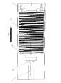
- FIG. 2 is a perspective view showing a common configuration example in the housing of the cache cassette 4 (# 1 to # 4) of FIG.
- the slide plate 6 is installed along a direction 101 in which a bundle 100 of banknotes in a standing state that are not bound are fed out.
- the push plate 7 is fitted to the slide plate 6 and can be moved forward and backward along the slide plate 6.
- the push plate 7 pushes out the banknote surface at one end of the banknote bundle 100 and feeds it one by one from the banknote bundle 100.
- variable load spring 8 is installed under the slide plate 6 and one end is fixed to the side on which the bill bundle 100 of the slide plate 6 is fed. The other end is fixed to a fixing portion 8d (not shown) that is fitted to the slide plate 6 of the push plate 7.
- the feeding roller 9 is installed on one end side of the slide plate 6 on which the banknote bundle 100 is fed out, and the banknote bundle 100 is pressed to feed paper sheets one by one from the banknote bundle 100.
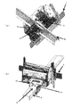
- FIG. 3 is a perspective view showing a detailed configuration example in the vicinity of the push plate 7 in FIG. 2
- FIG. 3 (a) is a perspective view seen from the lower side of the slide plate 6 in FIG. 2
- FIG. It is the perspective view seen from the upper side of the slide board 6 of FIG.
- a resin guide 10 is assembled to the push plate 7.
- the push plate 7 is fitted into the slide plate 6 by the guide 10 so as to freely advance and retreat along the slide plate 6.
- variable load spring 8 one end of a variable load spring 8 is fixed to a fixing portion 8d (not shown) at the lower part of the slide plate 6 of the guide 10 fitted to the slide plate 6. As shown in FIG. Further, in accordance with the movement of the push plate 7, the variable load spring 8 extending from the side of the feeding roller 9 below the slide plate 6 is wound around the fixed portion 8d.
- a roller 11 for allowing the guide 10 and the push plate 7 to move smoothly on the slide plate 6 is provided at a portion of the guide 10 in contact with the upper end of the slide plate 6. It is done.
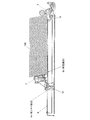
- FIGS. 4 and 5 are side cross-sectional views of the cash cassette 4 shown in FIGS. 2 and 3.
- FIG. 4 shows a state in which there are many banknotes in the banknote bundle 100.
- FIG. 5 shows a state in which there are few banknotes in the banknote bundle 100.
- variable load spring 8 is installed under the slide plate 6, and one end of the variable load spring 8 is a portion 12 on the side where the bill bundle 100 of the slide plate 6 is fed out as shown in FIG. 4 or 5. Fixed to. The other end is fixed and wound around a fixing portion 8d at the lower part of the slide plate 6 that fits into the slide plate 6 of the guide 10 assembled to the push plate 7.
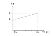
- FIG. 6 is a view showing a spring characteristic graph showing the load with respect to the spring length of the variable load spring spring 8 (length of the extended portion). As can be seen from this graph, the load varies according to the spring length. Therefore, by selecting an appropriate spring characteristic, the force with which the push plate 7 biases the banknote bundle 100 can be always controlled to an appropriate force according to the amount of banknotes in the banknote bundle 100. Become.
- the mainspring portion 8a of the variable load mainspring 8 is disposed on the pressing plate 7 side, but may be disposed on the feeding roller 9 side (for example, the portion 12 in FIG. 4).
- the above-mentioned embodiment is related with the cash cassette of the banknote dispenser for banknotes, for example, a stacker of a banknote recycling unit (BRU: Bill Recycle Unit) where banknotes are deposited and withdrawn.
- BRU bank Recycle Unit
- a similar configuration can be applied.
- a mechanism for feeding bills from the outside is added in a stacker corresponding to the configuration of FIG.
- the present invention can be implemented with respect to other paper sheets such as securities and tickets instead of banknotes.
- a slide plate not a slide plate but a bundle of paper sheets is placed on one or more table plates, and a groove or a plurality of tables installed in the direction in which the bundle of paper sheets on the table plate is fed out.
- a pressing plate or a guide assembled thereto may be fitted into a gap installed in a direction in which a bundle of paper sheets is fed out between the plates, and a variable load spring may be installed below the groove or the gap.
Landscapes
- Physics & Mathematics (AREA)
- General Physics & Mathematics (AREA)
- Engineering & Computer Science (AREA)
- Mechanical Engineering (AREA)
- Sheets, Magazines, And Separation Thereof (AREA)
Abstract
紙葉類格納装置および紙葉類取扱装置に関し、紙葉類の束を安定して繰出し可能とする。キャッシュカセット等の紙葉類格納装置において、変動荷重ゼンマイバネ8が、スライド板6の下に設置され、その一端はスライド板6の紙幣の束100が繰り出される一端側の部分12に固定される。他の一端は押し板7に組み付けられている樹脂製ガイド10のスライド板6に嵌合するスライド板6の下部の固定部8dに固定される。紙葉類の束の紙葉類が繰出しローラ9により順次繰り出されて押し板7が繰出しローラ9に近づくに従って、変動荷重ゼンマイバネ8のゼンマイ部分が巻き取られてゆき、押し板7に対して、巻き取りの状態に応じて変動する荷重を繰出しローラ9の方向に付勢する。この結果、紙葉類が多い状態では押し板7が紙幣の束100を大きな力で付勢し、少ない状態では小さな力で付勢し、紙葉類の束100を安定して繰り出すことが可能となる。
Description
本発明は、紙葉類格納装置および紙葉類取扱装置に関する。
紙葉類取扱装置、例えば紙幣出金機(BDU:Bill Dispenser Unit)は、ATM(Automated Teller Machine:現金自動預け払い機)に内蔵される等、紙葉類を処理する装置として普及している。
紙葉類取扱装置には、紙葉類を格納するためのスタッカまたはカセットである紙葉類格納装置が搭載される。この紙葉類格納装置においては、例えば紙葉類の種別(例えば紙幣の金種別)に設置され、種別ごとの紙葉類の束が立位状態で格納され、1枚ずつ繰り出される機能を備えている。
このような機能を実現するためには、繰出し側にローラを備え、紙葉類の束を繰出し側と反対の側から繰出し側の方向に向かって付勢する構成が必要となる。このような構成を備える紙葉類格納装置の従来技術として、次のようなものが知られている。
例えば、搬送方向に配置した複数のアイドルローラとこのアイドルローラの掛け回した無端ベルトからなる固定ガイドと、搬送路(搬送テーブル)をはさんで対応する位置に同様に構成された可動ガイドと、この可動ガイドを固定ガイド側に付勢する定荷重バネと、スライダ部及びガイド開閉機構部と、制御部とからなる構成により、紙葉束の厚さが変化した場合であっても、1000枚紙葉束を搬送することができる紙葉束搬送装置が知られている(例えば特許文献1に記載の技術)。
その他、一定荷重のバネによりカセット内部の紙幣を支える構造が知られている(例えば特許文献2または3に記載の技術)。
紙葉類格納装置において、結束されていない紙葉類の束を1枚ずつ繰り出すためには、紙葉類の束が大量に格納装置内に滞留しているときには、紙葉類の束を大きな力で繰出し方向に付勢する必要がある。一方、紙葉類の束が少量しか格納装置内に滞留していないときには、紙葉類の束を付勢する力を弱くしないと、紙葉類または紙葉類の束が詰まってしまったり、複数枚の紙葉類が繰り出されてしまったりする場合がある。しかし、上述した従来技術はいずれも、一定荷重の付勢力で紙葉類の束を押し出す構成を有しており、このような場合に対処することができないという課題があった。
そこで、本発明の一つの側面では、紙葉類の束を安定して繰出し可能とすることを目的とする。
態様の一例は、結束されていない立位状態の紙葉類の束が繰り出される方向に沿って設置されたスライド板と、スライド板に嵌合してそのスライド板に沿って進退自在に移動可能であって、紙葉類の束の一端の紙葉類面を押して紙葉類の束を繰り出す押し板と、スライド板下に設置され、一端がスライド板の紙葉類の束が繰り出される一端側に固定される。他の一端は押し板のスライド板に嵌合する固定部に固定され、その押し板が紙葉類の束が繰り出される位置に近づくに従って巻き取られてゆき、押し板に対して、巻き取りの状態に応じて変動する荷重を紙葉類の束が繰り出される方向に付勢する変動荷重ゼンマイバネと、スライド板の紙葉類の束が繰り出される一端側に設置され、紙葉類の束が押しつけられてその紙葉類の束から紙葉類を1枚ずつ繰り出す繰出しローラと、を備える。
紙葉類の束を安定して繰り出すことが可能となる。
以下、本発明を実施するための形態(以下、「本実施形態」)について図面を参照しながら詳細に説明する。図1は、本実施形態である紙幣出金機(BDU)の構成例を示す側面断面図である。この紙幣出金機は、例えばATMに搭載されるものである。
図1に示す紙幣出金機1は、BV(Bill Validator:紙幣鑑別機)3を有する。ここでいうBVとは、紙幣の厚みや長さで判定する簡易的な構成も含む。
紙幣出金機1において、例えば、4台のキャッシュカセット4(#1~#4)は、それぞれ着脱可能に構成され、外部から紙幣の束を装填することができる。例えば、キャッシュカセット4(#1)は一万円札を収納し、キャッシュカセット4(#2)は五千円札を収納し、キャッシュカセット4(#3)は千円札を収納し、キャッシュカセット4(#4)は予備である。
紙幣出金機1において、紙幣の出金時には、キャッシュカセット4(#1~#4)に収納されている紙幣は、出金搬送路5を通ってBV3に搬送され、BV3によって鑑別される。金種及び記番号が判別できて鑑別結果が「OK」となった紙幣は、BV3から排出後、出金口2へ搬送されて出金される。一方で、出金時に鑑別結果が「NG」となった紙幣は、紙幣出金機1内の所定のリジェクトボックス(図示せず)に搬送されて収納される。
図2は、図1のキャッシュカセット4(#1~#4)の筐体内の共通の構成例を示す斜視図である。
スライド板6は、結束されていない立位状態の紙幣の束100が繰り出される方向101に沿って設置される。
押し板7は、スライド板6に嵌合して、スライド板6に沿って進退自在に移動可能であって、紙幣の束100の一端の紙幣面を押して紙幣の束100から1枚ずつ繰り出す。
変動荷重ゼンマイバネ8は、スライド板6の下に設置され、一端がスライド板6の紙幣の束100が繰り出される側に固定される。他の一端は押し板7のスライド板6に嵌合する固定部8d(不図示)に固定される。
繰出しローラ9は、スライド板6の紙幣の束100が繰り出される一端側に設置され、紙幣の束100が押しつけられて紙幣の束100から紙葉類を1枚ずつ繰り出す。
図3は、図2の押し板7の付近の詳細構成例を示す斜視図であり、図3(a)は図2のスライド板6の下側から見た斜視図、図3(b)は図2のスライド板6の上側から見た斜視図である。
図3(b)に示されるように、押し板7には、樹脂製のガイド10が組み付けられている。押し板7は、このガイド10によって、スライド板6に沿って進退自由にスライド板6に嵌合する。
図3(a)に示されるように、スライド板6に嵌合するガイド10のスライド板6下部には変動荷重ゼンマイバネ8の一端が固定部8d(不図示)に固定される。また、押し板7の移動に応じて、スライド板6下部の繰出しローラ9側から伸びている変動荷重ゼンマイバネ8が固定部8dに巻き取られる。
図3(b)に示されるように、ガイド10のスライド板6の上端に接する部分には、ガイド10および押し板7がスライド板6上で平滑に移動できるようにするためのローラ11が備えられる。
上述の構成を有する本実施形態の動作について、図4から図6の説明図に従って、以下に説明する。
図4および図5は、図2および図3のキャッシュカセット4の側面断面図である。図4は紙幣の束100の紙幣が多い状態を示している。図5は紙幣の束100の紙幣が少ない状態を示している。
前述したように、変動荷重ゼンマイバネ8は、スライド板6の下に設置され、その一端は、図4または図5に示されるように、スライド板6の紙幣の束100が繰り出される側の部分12に固定される。他の一端は押し板7に組み付けられているガイド10のスライド板6に嵌合するスライド板6の下部の固定部8dに固定されて巻き取られる。
ここで、図4に示されるように、紙幣の束100の紙幣が多い状態では、押し板7は紙幣の束100によって繰出しローラ9側から遠ざかるため、変動荷重ゼンマイバネ8の伸長部分8bが長くなり、変動荷重ゼンマイバネ8のゼンマイ部分8aの巻き取り量は少なくなる。この結果、変動荷重ゼンマイバネ8の長くなった伸長部8bによって、ガイド10から押し板7にかかる繰出しローラ9方向への荷重は大きくなり、紙幣の束100は強い力で繰出しローラ9側に付勢される。故に、紙幣が多い状態では、大きな紙幣の束100が、押し板7が押す十分な力によって繰出しローラ9側に付勢されることになる。
逆に、図5に示されるように、紙幣の束100の紙幣が少ない状態では、押し板7は繰出しローラ9側に近づくため、変動荷重ゼンマイバネ8の伸長部分8cが短くなり、変動荷重ゼンマイバネ8のゼンマイ部分の巻き取り量は多くなる。この結果、変動荷重ゼンマイバネ8の短くなった伸長部8cによって、ガイド10から押し板7にかかる繰出しローラ9方向への荷重は小さくなり、紙幣の束100は小さい力で繰出しローラ9側に付勢される。故に、紙幣が少ない状態では、押し板7が押す力によって紙幣が詰まることを回避できる。
図6は、変動荷重ゼンマイバネ8のバネ長さ(伸長部分の長さ)に対する荷重を示すバネ特性グラフを示す図である。このグラフからわかるように、バネ長さに応じて荷重が変動する。従って、適切なバネの特性を選択することで、押し板7が紙幣の束100に付勢する力を、紙幣の束100の紙幣の量に応じて常に適切な力に制御することが可能となる。
以上説明した実施形態において、変動荷重ゼンマイバネ8のゼンマイ部分8aは、押し板7側に配置されたが、繰出しローラ9側(例えば図4の部分12)に配置してもよい。
また、上述の実施形態は、紙幣を対象とした紙幣出金機のキャッシュカセットに関するものであるが、紙幣の入出金が行われる例えば紙幣リサイクルユニット(BRU:Bill Recycle Unit)のスタッカなどに対しても、同様の構成を適用することが可能である。この場合には、特には図示しないが、例えば図2の構成に相当するスタッカにおいて、紙幣を外部から繰り入れる機構が追加される。
また、紙幣ではなく、例えば有価証券やチケット等の他の紙葉類に関して本発明を実施することも可能である。
さらに、スライド板ではなく、紙葉類の束が1枚または複数枚のテーブル板上に置かれ、そのテーブル板の紙葉類の束が繰り出される方向に設置された溝、または複数枚のテーブル板間の紙葉類の束が繰り出される方向に設置された間隙に、押し板またはそれに組み付けられたガイドが嵌合され、その溝または間隙の下部に変動荷重ゼンマイバネが設置されてもよい。
以上説明した実施形態およびその変形例により、紙葉類の束を安定して繰り出すことが可能となる。
1 紙幣出金機
2 出金口
3 BV(Bill Validator:紙幣鑑別機)
4 キャッシュカセット
5 出金搬送路
6 スライド板
7 押し板
8 変動荷重ゼンマイバネ
8a ゼンマイ部分
8b 伸長部分(長)
8c 伸長部分(短)
8d 固定部
9 繰出しローラ
10 ガイド
11 ローラ
100 紙幣の束
2 出金口
3 BV(Bill Validator:紙幣鑑別機)
4 キャッシュカセット
5 出金搬送路
6 スライド板
7 押し板
8 変動荷重ゼンマイバネ
8a ゼンマイ部分
8b 伸長部分(長)
8c 伸長部分(短)
8d 固定部
9 繰出しローラ
10 ガイド
11 ローラ
100 紙幣の束
Claims (6)
- 結束されていない立位状態の紙葉類の束が繰り出される方向に沿って設置されたスライド板と、
前記スライド板に嵌合して当該スライド板に沿って進退自在に移動可能であって、前記紙葉類の束の一端の紙葉類面を押して前記紙葉類の束を繰り出す押し板と、
前記スライド板下に設置され、一端が前記スライド板の前記紙葉類の束が繰り出される側に固定され、他の一端は前記押し板の前記スライド板に嵌合する部分に固定され、当該押し板が前記紙葉類の束が繰り出される位置に近づくに従って巻き取られてゆき、前記押し板に対して、巻き取りの状態に応じて変動する荷重を前記紙葉類の束が繰り出される方向に付勢する変動荷重ゼンマイバネと、
前記スライド板の前記紙葉類の束が繰り出される一端側に設置され、前記紙葉類の束が押しつけられて当該記紙葉類の束から前記紙葉類を1枚ずつ繰り出す繰出しローラと、
を備えることを特徴とする紙葉類格納装置。 - 前記押し板は、当該押し板に組み付けられたガイドによって前記スライド板に嵌合し、当該ガイドの前記スライド板下部で前記変動荷重ゼンマイバネの一端を巻き取ることを特徴とする請求項1に記載の紙葉類格納装置。
- 前記ガイドの前記スライド板の上端に接する部分にローラを備えることを特徴とする請求項2に記載の紙葉類格納装置。
- 結束されていない立位状態の紙葉類の束が置かれ、当該紙葉類の束が所定の方向に繰り出される1枚または複数枚のテーブル板と、
前記テーブル板の前記紙葉類の束が繰り出される方向に設置された溝、または前記複数枚のテーブル板間の前記紙葉類の束が繰り出される方向に設置された間隙に嵌合し、当該溝または間隙に沿って進退自在に移動可能であって、前記紙葉類の束の一端の紙葉類面を押して前記紙葉類の束を繰り出す押し板と、
前記溝または間隙の下部に設置され、一端が前記スライド板の前記紙葉類の束が繰り出される一端側に固定され、他の一端は前記押し板の前記溝または間隙に嵌合する部分に固定され、当該押し板が前記紙葉類の束が繰り出される位置に近づくに従って巻き取られてゆき、前記押し板に対して、巻き取りの状態に応じて変動する荷重を前記紙葉類の束が繰り出される方向に付勢する変動荷重ゼンマイバネと、
前記溝または間隙の前記紙葉類の束が繰り出される一端側に設置され、前記紙葉類の束が押しつけられて当該紙葉類の束から前記紙葉類を1枚ずつ繰り出す繰出しローラと、
を備えることを特徴とする紙葉類格納装置。 - 前記紙葉類は紙幣であることを特徴とする請求項1ないし4のいずれかに記載の紙葉類格納装置。
- 請求項1ないし5のいずれかに記載の紙葉類格納装置と、
前記紙葉類格納装置から繰り出された紙葉類を判別する紙葉類判別装置と、
前記紙葉類判別装置で判別された紙葉類を外部に供給する紙葉類供給装置と、
を備えることを特徴とする紙葉類取扱装置。
Priority Applications (2)
| Application Number | Priority Date | Filing Date | Title |
|---|---|---|---|
| JP2017501792A JP6363290B2 (ja) | 2015-02-27 | 2015-02-27 | 紙葉類格納装置および紙葉類取扱装置 |
| PCT/JP2015/055842 WO2016135946A1 (ja) | 2015-02-27 | 2015-02-27 | 紙葉類格納装置および紙葉類取扱装置 |
Applications Claiming Priority (1)
| Application Number | Priority Date | Filing Date | Title |
|---|---|---|---|
| PCT/JP2015/055842 WO2016135946A1 (ja) | 2015-02-27 | 2015-02-27 | 紙葉類格納装置および紙葉類取扱装置 |
Publications (1)
| Publication Number | Publication Date |
|---|---|
| WO2016135946A1 true WO2016135946A1 (ja) | 2016-09-01 |
Family
ID=56788190
Family Applications (1)
| Application Number | Title | Priority Date | Filing Date |
|---|---|---|---|
| PCT/JP2015/055842 Ceased WO2016135946A1 (ja) | 2015-02-27 | 2015-02-27 | 紙葉類格納装置および紙葉類取扱装置 |
Country Status (2)
| Country | Link |
|---|---|
| JP (1) | JP6363290B2 (ja) |
| WO (1) | WO2016135946A1 (ja) |
Citations (6)
| Publication number | Priority date | Publication date | Assignee | Title |
|---|---|---|---|---|
| JPS5598036A (en) * | 1979-01-20 | 1980-07-25 | Omron Tateisi Electronics Co | Sheet delivery cassette device |
| JPS56165638A (en) * | 1980-05-24 | 1981-12-19 | Mitsubishi Heavy Ind Ltd | Hopper |
| JPS61267617A (ja) * | 1985-05-22 | 1986-11-27 | Hitachi Ltd | 紙葉類収納装置 |
| JPS62176128U (ja) * | 1986-04-28 | 1987-11-09 | ||
| JPH08175702A (ja) * | 1994-12-22 | 1996-07-09 | Tooin Kk | 積層シート類の分配装置 |
| JP2003044898A (ja) * | 2002-06-03 | 2003-02-14 | Hitachi Ltd | 紙幣カセット及び自動取引装置 |
-
2015
- 2015-02-27 WO PCT/JP2015/055842 patent/WO2016135946A1/ja not_active Ceased
- 2015-02-27 JP JP2017501792A patent/JP6363290B2/ja not_active Expired - Fee Related
Patent Citations (6)
| Publication number | Priority date | Publication date | Assignee | Title |
|---|---|---|---|---|
| JPS5598036A (en) * | 1979-01-20 | 1980-07-25 | Omron Tateisi Electronics Co | Sheet delivery cassette device |
| JPS56165638A (en) * | 1980-05-24 | 1981-12-19 | Mitsubishi Heavy Ind Ltd | Hopper |
| JPS61267617A (ja) * | 1985-05-22 | 1986-11-27 | Hitachi Ltd | 紙葉類収納装置 |
| JPS62176128U (ja) * | 1986-04-28 | 1987-11-09 | ||
| JPH08175702A (ja) * | 1994-12-22 | 1996-07-09 | Tooin Kk | 積層シート類の分配装置 |
| JP2003044898A (ja) * | 2002-06-03 | 2003-02-14 | Hitachi Ltd | 紙幣カセット及び自動取引装置 |
Also Published As
| Publication number | Publication date |
|---|---|
| JPWO2016135946A1 (ja) | 2017-04-27 |
| JP6363290B2 (ja) | 2018-07-25 |
Similar Documents
| Publication | Publication Date | Title |
|---|---|---|
| US8708327B2 (en) | Paper sheet handling machine | |
| JP5274999B2 (ja) | 紙幣取扱装置 | |
| JP5856695B2 (ja) | 紙葉類取扱装置 | |
| JP4945424B2 (ja) | 紙葉類分離集積装置 | |
| JP5732367B2 (ja) | 紙幣取扱装置 | |
| KR102417037B1 (ko) | 금융자동화기기의 지폐류 저장장치 | |
| JP6363290B2 (ja) | 紙葉類格納装置および紙葉類取扱装置 | |
| KR101396190B1 (ko) | 스택가이드 | |
| KR101865141B1 (ko) | 지폐 처리 장치 | |
| JP2010052884A (ja) | 紙葉類取扱装置 | |
| JP5176739B2 (ja) | 紙幣処理装置及び金銭処理機 | |
| JP2009211572A (ja) | 紙幣処理装置及び金銭処理機 | |
| JP2018088071A (ja) | 媒体処理装置及び媒体取引装置 | |
| KR102303715B1 (ko) | 갭롤러를 구비한 다권종 지폐카세트 | |
| KR20170044944A (ko) | 에스크로우 장치 | |
| KR20160011763A (ko) | 매체 처리 장치의 제어방법 | |
| KR101750932B1 (ko) | 지폐류 저장장치 | |
| JP2007041826A (ja) | 紙幣入出金装置および現金自動取引装置 | |
| JP2008186314A (ja) | 紙葉類繰出装置及び紙葉類集積装置 | |
| JP2906022B2 (ja) | 紙幣自動支払い装置 | |
| JP6728762B2 (ja) | 媒体処理装置 | |
| JP5245514B2 (ja) | 紙葉類の保留集積装置 | |
| KR20170089304A (ko) | 다권종 지폐 저장 장치 | |
| WO2018123331A1 (ja) | 媒体分離装置、媒体収納庫及び媒体取引装置 | |
| HK1258981B (zh) | 纸币处理装置 |
Legal Events
| Date | Code | Title | Description |
|---|---|---|---|
| 121 | Ep: the epo has been informed by wipo that ep was designated in this application |
Ref document number: 15883240 Country of ref document: EP Kind code of ref document: A1 |
|
| ENP | Entry into the national phase |
Ref document number: 2017501792 Country of ref document: JP Kind code of ref document: A |
|
| NENP | Non-entry into the national phase |
Ref country code: DE |
|
| 122 | Ep: pct application non-entry in european phase |
Ref document number: 15883240 Country of ref document: EP Kind code of ref document: A1 |