WO2016129628A1 - タービン及びガスタービン - Google Patents
タービン及びガスタービン Download PDFInfo
- Publication number
- WO2016129628A1 WO2016129628A1 PCT/JP2016/053925 JP2016053925W WO2016129628A1 WO 2016129628 A1 WO2016129628 A1 WO 2016129628A1 JP 2016053925 W JP2016053925 W JP 2016053925W WO 2016129628 A1 WO2016129628 A1 WO 2016129628A1
- Authority
- WO
- WIPO (PCT)
- Prior art keywords
- blade
- blade height
- height direction
- flow path
- hub
- Prior art date
- Legal status (The legal status is an assumption and is not a legal conclusion. Google has not performed a legal analysis and makes no representation as to the accuracy of the status listed.)
- Ceased
Links
Images



Classifications
-
- F—MECHANICAL ENGINEERING; LIGHTING; HEATING; WEAPONS; BLASTING
- F01—MACHINES OR ENGINES IN GENERAL; ENGINE PLANTS IN GENERAL; STEAM ENGINES
- F01D—NON-POSITIVE DISPLACEMENT MACHINES OR ENGINES, e.g. STEAM TURBINES
- F01D5/00—Blades; Blade-carrying members; Heating, heat-insulating, cooling or antivibration means on the blades or the members
- F01D5/12—Blades
- F01D5/14—Form or construction
- F01D5/141—Shape, i.e. outer, aerodynamic form
-
- F—MECHANICAL ENGINEERING; LIGHTING; HEATING; WEAPONS; BLASTING
- F01—MACHINES OR ENGINES IN GENERAL; ENGINE PLANTS IN GENERAL; STEAM ENGINES
- F01D—NON-POSITIVE DISPLACEMENT MACHINES OR ENGINES, e.g. STEAM TURBINES
- F01D5/00—Blades; Blade-carrying members; Heating, heat-insulating, cooling or antivibration means on the blades or the members
- F01D5/12—Blades
- F01D5/14—Form or construction
-
- F—MECHANICAL ENGINEERING; LIGHTING; HEATING; WEAPONS; BLASTING
- F01—MACHINES OR ENGINES IN GENERAL; ENGINE PLANTS IN GENERAL; STEAM ENGINES
- F01D—NON-POSITIVE DISPLACEMENT MACHINES OR ENGINES, e.g. STEAM TURBINES
- F01D5/00—Blades; Blade-carrying members; Heating, heat-insulating, cooling or antivibration means on the blades or the members
- F01D5/12—Blades
- F01D5/14—Form or construction
- F01D5/141—Shape, i.e. outer, aerodynamic form
- F01D5/145—Means for influencing boundary layers or secondary circulations
-
- F—MECHANICAL ENGINEERING; LIGHTING; HEATING; WEAPONS; BLASTING
- F05—INDEXING SCHEMES RELATING TO ENGINES OR PUMPS IN VARIOUS SUBCLASSES OF CLASSES F01-F04
- F05D—INDEXING SCHEME FOR ASPECTS RELATING TO NON-POSITIVE-DISPLACEMENT MACHINES OR ENGINES, GAS-TURBINES OR JET-PROPULSION PLANTS
- F05D2240/00—Components
- F05D2240/20—Rotors
- F05D2240/30—Characteristics of rotor blades, i.e. of any element transforming dynamic fluid energy to or from rotational energy and being attached to a rotor
Definitions
- the present invention relates to a turbine and a gas turbine. This application claims priority based on Japanese Patent Application No. 2015-024441 for which it applied on February 10, 2015, and uses the description.
- Patent Document 1 discloses a wing structure in which a fillet portion for improving the strength of a wing body is provided at a hub-side base end.
- This invention is made
- the turbine has a blade body extending outward in the radial direction of the axis, and a flow path is provided between the adjacent blade bodies by being arranged in the circumferential direction of the axis.
- a plurality of moving blades formed, and a flow path width at a hub-side base end of the blade body decreases after increasing from a leading edge toward a trailing edge and increases after the minimum value, and the hub of the blade body
- the flow path width at the reference blade height direction position spaced from the side base end toward the tip side gradually decreases from the front edge toward the rear edge, and the minimum value of the flow path width at each blade height direction position
- the axial code length direction position of the blade is shifted from the hub-side base end of the blade body toward the tip side to the trailing edge side, and coincides with the trailing edge at the reference blade height direction position.
- the flow path width is narrowed on the rear edge side of the reference blade height direction position, and the flow path width is enlarged on the rear edge side of the hub side base end.
- the flow is three-dimensionally redistributed so that the flow is guided from the reference blade height direction position side to the hub side base end side.
- the reference blade height direction position is 5% or more and 25% or less of the blade height from the hub side base end toward the tip side. It may be located in the area.
- the reference blade height direction position is an area of 5% or more of the blade height.
- the reference blade height direction position is set in the above range, it is possible to effectively guide the flow to the hub side base end while ensuring the strength of the moving blade. .
- the passage width at each blade height direction position at the trailing edge of the blade body is defined as the trailing edge passage width.
- the flow width at each blade height direction position at the axial code length direction ratio position of the axial code length direction position at which the flow path width has the minimum value at the hub side base end of the blade body is defined as the hub throat position flow width.
- the ratio of the trailing edge channel width to the hub throat position channel width at each blade height direction position is defined as a channel width ratio, and the ratio of the channel width ratio gradually decreases from the hub side toward the tip side.
- the blade height direction position where the value is 1 is defined as the transition position
- the blade height direction position of the transition position is within a region within 10% of the blade height from the hub side base end toward the tip side. May be located.
- the trailing edge side is enlarged at the blade height direction position where the channel width ratio value exceeds 1, the flow rate for maintaining the flow velocity on the trailing edge side is insufficient.
- the trailing edge side is reduced, so that the flow rate is sufficient on the trailing edge side. Therefore, on the trailing edge side, the flow at the blade height direction position where the channel width ratio value is less than 1 can be guided to the blade height direction position where the channel width ratio value exceeds 1. Then, by setting the blade height direction position of the transition position where the value of the channel width ratio is 1 to a region within 10% of the blade height, the blade height direction position where the flow rate on the trailing edge side is insufficient is set. , Can effectively induce the flow.
- the maximum value of the flow path width ratio in the region within 10% of the blade height from the hub side proximal end toward the tip side is set.
- the minimum channel width ratio ⁇ is defined as the minimum channel width ratio ⁇ in the region within 20% of the blade height from the hub side base end toward the tip side
- the maximum channel width ratio ⁇ is defined.
- may be established.
- Blade height direction position where the flow rate on the trailing edge side is insufficient because the absolute value of the difference between the minimum flow path ratio ⁇ and 1 is larger than the absolute value of the difference between the maximum flow path ratio ⁇ and 1 In addition, the flow can be effectively induced.
- the horizontal axis X is the flow path width ratio
- the vertical axis Y is from the hub side to the tip side with respect to the blade height.
- the gas turbine includes a compressor that compresses air to generate compressed air, a combustor that generates the combustion gas by burning the compressed air together with fuel, and the combustion gas. And the turbine according to any one of the first to fifth aspects driven by the above.
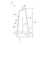
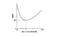
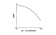
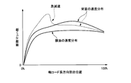
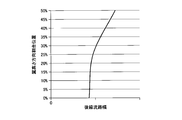
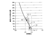
- FIG. 1 is an overall schematic diagram of a gas turbine according to a first embodiment of the present invention. It is a typical side view of the blade body in the moving blade of the turbine concerning a first embodiment of the present invention. It is sectional drawing orthogonal to the blade height direction which shows the flow path between the adjacent moving blades in the turbine which concerns on 1st embodiment of this invention. It is a graph which shows the relationship between the axial code length direction ratio position and flow path width in the blade height direction ratio position 0% in the turbine which concerns on 1st embodiment of this invention. It is a graph which shows the relationship between the axial code length direction ratio position and flow path width in the blade height direction ratio position 25% (reference
- the gas turbine 1 includes a compressor 3, a combustor 4, a turbine 5, and a rotor 2.
- the compressor 3 produces
- the combustor 4 generates combustion gas by mixing fuel with the compressed air generated by the compressor 3 and burning it.
- the turbine 5 rotates when the combustion gas generated in the combustor 4 is introduced into the turbine 5 and the thermal energy of the combustion gas is converted into rotational energy.
- the rotor 2 is rotatable around the axis O, takes out the rotating power of the turbine 5 to the outside, and transmits a part of the power to the compressor 3 to rotate the compressor 3.
- the blade thickness increases accordingly.
- the blade thickness is large between the leading edge 25 and the trailing edge 26 in order to improve the strength of the blade body 20, and therefore, there is a flow between the leading edge 25 and the trailing edge 26.
- the road width W is minimized.
- the minimum flow path width position line m continuously transitions from the hub side base end 21 toward the reference blade height direction position S toward the trailing edge 26.
- the three-dimensional redistribution of the flow rate as described above is performed over the entire range. Accordingly, it is possible to optimize the flow in the entire transition range, and it is possible to effectively suppress the rapid deceleration of the flow velocity on the blade back surface 24 in the region on the hub side proximal end 21 side.
- FIG. 8 shows the relationship between the hub throat position channel width and the blade height direction ratio position in the channel F of the turbine 5 of the second embodiment.
- FIG. 8 shows a range of the blade height direction ratio position of 0 to 50% for the relationship.
- the hub throat position channel width is the same axis code at each blade height position with respect to the axis code length ratio position at which the channel width W is the minimum value at the hub-side proximal end 21 of the blade body 20. It means the channel width W at the long proportion position.
- the hub throat position line L indicating the transition of the position of the hub throat position channel width extends from the position where the channel width W at the hub-side base end 21 shows the minimum value toward the blade height direction. ing.
- the channel width at the position where the shaft code length ratio position at each blade height position is 30% W is the hub throat position channel width.
- the hub throat position flow path width monotonously increases from the hub side base end 21 in the blade height direction to reach the blade height direction ratio position 50%.
- the blade height direction ratio position where the channel width ratio is 1 is referred to as a transition position N.
- the transition position N is not limited to the blade height direction ratio position of 8 to 9%, and may be any value as long as it is within 10% of the blade height direction ratio position.
- the maximum value of the channel width ratio in the region where the blade height direction ratio position is within 10% is defined as the maximum channel width ratio ⁇ .
- the minimum value of the channel width ratio in the region where the blade height direction ratio position is within 20% is defined as the minimum channel width ratio ⁇ .
Landscapes
- Engineering & Computer Science (AREA)
- Mechanical Engineering (AREA)
- General Engineering & Computer Science (AREA)
- Physics & Mathematics (AREA)
- Fluid Mechanics (AREA)
- Turbine Rotor Nozzle Sealing (AREA)
Abstract
Description
本願は、2015年2月10日に出願された特願2015-024441に基づいて優先権を主張し、その記載を援用する。
しかしながら上記の構成によれば、基準翼高さ方向位置が上記範囲に設定されていることで、動翼の強度を確保しながらハブ側基端への流れの誘導を効果的に行うことができる。
前記タービン動翼のハブ側基端における流路幅は、前縁から後縁に向かうに従って減少して極小値を示した後に増加し、前記タービン動翼のハブ側基端からチップ側に向かって離間した基準翼高さ方向位置での流路幅は、前記前縁から前記後縁に向かうに従って漸次小さくなり、各翼高さ方向位置における前記流路幅の最小値の軸コード長方向位置が、前記タービン動翼のハブ側基端からチップ側に向かうに従って後縁側に遷移して、前記基準翼高さ方向位置で前記後縁に一致する。
図1に示すように、ガスタービン1は、圧縮機3、燃焼器4、タービン5及びロータ2を備えている。圧縮機3は、空気を内部に取り入れて圧縮することで圧縮空気を生成する。燃焼器4は、圧縮機3で生成された圧縮空気に燃料を混合して燃焼させることで燃焼ガスを生成する。タービン5は、燃焼器4で生成された燃焼ガスがその内部に導入され、該燃焼ガスの熱エネルギーを回転エネルギーに変換して回動する。ロータ2は、軸線O回りに回転可能とされており、タービン5の回動する動力を外部に取り出すとともに該動力の一部を圧縮機3に伝達して圧縮機3を回動させる。
動翼10はロータ2の軸線O方向に流れる燃焼ガスの圧力を受けて軸線O回りにロータ2を回転させ、ロータ2に与えられた回転エネルギーは軸端から取り出されて利用される。
図2に示すように、動翼10は、ロータ2から軸線Oの径方向外側に向かって延在する翼本体20を有している。なお、翼本体20の基端側、即ち、ロータ2側には、プラットホーム及び翼根(それぞれ図示省略)が設けられている。そして、翼根がロータ2に一体に形成されたディスク(図示省略)に嵌め込まれることで、動翼10がロータ2に強固に固定されている。
さらに、極小値を示す前の単調減少する際の流路幅Wの変化の度合いは、極小値を示した後の変化の度合いに比べて大きい。以上のように、ハブ側基端21では、前縁25側から後縁26側に向かって流路幅Wが縮小して一旦最小値を示した後に流路幅Wが拡大しながら後縁26に至る。
流路幅Wが小さい軸コード長方向割合位置では、その分だけ翼厚が大きくなる。ハブ側基端21では、翼本体20の強度向上のために前縁25と後縁26との間に翼厚が大きい部分があり、このため、前縁25と後縁26との間に流路幅Wが極小となる部分が存在する。
なお、翼高さ方向割合位置が基準翼高さ方向位置Sよりもチップ22側の範囲では、後縁26での流路幅Wが最小となる。
これにより、後縁26側では、基準翼高さ方向位置S側からハブ側基端21側に向かって流れが誘導される(図2の矢印R参照)。即ち、基準翼高さ方向位置Sでの狭い流路Fからハブ側基端21での広い流路Fに向かって流れが誘導されるように、流量の三次元的な再配分が行われる。このため、ハブ側基端21の後縁26側の流量が増加するため、該ハブ側基端21における背面24での流速の急減速を抑制することができる。
当該解析結果からも分かるように、従来形状では、背面24で流れの急減速が発生し、その結果、流速分布が悪化している。一方、本実施形態の形状では、背面24での流速分布が改善され、流れの急減速が発生しない。これは、上述したように、後縁26側においてチップ22側からハブ側基端21に流れが誘導されたことにより、ハブ側基端21の最小流路幅Wを通過する流体に大きな減速が生じず、流速が安定したことによるものである。
ここで、動翼10の強度の確保のため、ハブ側基端からチップ22側に向かって翼高さの5%未満の領域では、軸コード長Cの中央付近での翼厚が大きくなる。したがって、基準翼高さ方向位置Sは翼高さHの5%以上の領域となる。一方、基準翼高さ方向位置Sが、翼高さの25%を超える領域に位置していては、基準翼高さ方向位置Sがハブ側基端21から離間し過ぎているため、該基準翼高さ方向位置Sからハブ側基端21に向かって流れを効果的に誘導することができない。
したがって、基準翼高さ方向位置Sを翼高さ方向割合位置の5%~25%の範囲に設定することで、動翼10の強度を確保しながらハブ側基端21への流れの誘導を効果的に行うことができる。
ここで、ハブスロート位置流路幅とは、翼本体20のハブ側基端21で流路幅Wが最小値を示す軸コード長割合位置に対して、各翼高さ位置での同一の軸コード長割合位置における流路幅Wを意味している。図2に示すように、ハブスロート位置流路幅の位置の遷移を示すハブスロート位置ラインLは、ハブ側基端21での流路幅Wが最小値を示す位置から翼高さ方向に向かって延びている。例えば、ハブ側基端21での流路幅Wが最小値を示す軸コード長割合位置が30%の場合、各翼高さ位置での軸コード長割合位置が30%の位置の流路幅Wがハブスロート位置流路幅となる。
図8に示す通り、ハブスロート位置流路幅は、ハブ側基端21から翼高さ方向に向かうに従って単調に増加して翼高さ方向割合位置50%に至る。
ここで、流路幅比とは、各翼高さ位置におけるハブスロート位置流路幅に対する後縁26の流路幅W(後縁流路幅)の比(後縁流路幅/ハブスロート位置流路幅)を意味している。
図9に示す通り、流路幅比は、ハブ側基端21(翼高さ方向割合位置0%)で1よりも大きい値を示し、翼高さ方向に向かうに従って単調に減少し、翼高さ方向割合位置10%手前、より詳細には8~9%程で1を示し、さらに翼高さ方向に向かうに従って単調に減少して翼高さ方向割合位置50%に至る。なお、以下では、流路幅比が1を示す翼高さ方向割合位置を遷移位置Nと称する。この遷移位置Nは、翼高さ方向割合位置8~9%に限られず、翼高さ方向割合位置10%以内ならばいずれの値であってもよい。
|β-1|>|α―1|
の関係が成立していることが好ましい。
図9の横軸(流路幅比)をX軸とし、縦軸(翼高さ方向割合位置)をY軸とすると、最大流路幅比αは、図9のカーブとY=0〔%〕との交点となる。したがって、|α―1|は、当該交点とX=1との距離となる。
一方、最小流路幅日ベータは、図9のカーブとY=20[%]の交点となる。したがって、|β―1|は、当該交点とX=1との距離となる。
流路幅比が1よりも大きい領域では流量が不足しているため、|α―1|の値は、翼高さ方向の範囲における流量の不足量に相関する。一方、流路幅比が1よりも小さい領域では流量が十分であるため、|β―1|は流量の過剰量に相関する。したがって、|β-1|>|α―1|の関係が成立していれば、流量の不足量よりも供給できる流量が上回っていることを意味している。したがって、当該関係が成立することで、後縁26側での流量が不足する翼高さ方向位置に、効果的に流れを誘導することができる。
流路幅比が1よりも大きい領域では流量が不足しているため、流路幅比が1よりも大きい領域の一部を占める面積Aは、翼高さ方向の範囲における流量の不足量に相関する。一方、流路幅比が1よりも小さい領域では流量が十分であるため、流路幅比が1よりも小さい領域の一部を占める面積Bは流量の過剰量に相関する。したがって、B>Aの関係が成立していれば、流量の不足量よりも供給できる流量が上回っていることを意味している。したがって、当該関係が成立することで、後縁26側での流量が不足する翼高さ方向位置に、より効果的に流れを誘導することができる。
2 ロータ
3 圧縮機
4 燃焼器
5 タービン
6 ケーシング
7 静翼
10 動翼
20 翼本体
21 ハブ側基端
22 チップ
23 腹面
24 背面
25 前縁
26 後縁
H 翼高さ
C 軸コード長
S 基準翼高さ方向位置
m 流路幅最小位置ライン
L ハブスロート位置ライン
N 遷移位置
O 軸線
U 回転方向
R 矢印
W 流路幅
X ハブ側基端のスロートの軸コード長方向割合位置
Claims (7)
- 軸線の径方向外側に延びる翼本体を有し、前記軸線の周方向に配列されることで隣り合う前記翼本体同士の間に流路が形成される複数の動翼を備え、
前記翼本体のハブ側基端における流路幅は、前縁から後縁に向かうに従って減少して極小値を示した後に増加し、
前記翼本体のハブ側基端からチップ側に向かって離間した基準翼高さ方向位置での流路幅は、前記前縁から前記後縁に向かうに従って漸次小さくなり、
各翼高さ方向位置における前記流路幅の最小値の軸コード長方向位置が、前記翼本体のハブ側基端からチップ側に向かうに従って後縁側に遷移して、前記基準翼高さ方向位置で前記後縁に一致するタービン。 - 前記基準翼高さ方向位置は、ハブ側基端からチップ側に向かって翼高さの5%以上25%以下の領域に位置している請求項1に記載のタービン。
- 前記翼本体の前記後縁における各翼高さ方向位置の前記流路幅を後縁流路幅と定義し、
前記翼本体のハブ側基端で前記流路幅が最小値を示す軸コード長方向割合位置における各翼高さ方向位置の前記流路幅をハブスロート位置流路幅と定義し、
各翼高さ方向位置における前記ハブスロート位置流路幅に対する前記後縁流路幅の比を流路幅比と定義し、
ハブ側からチップ側に向かうに従って漸次小さくなる前記流路幅比の値が1となる翼高さ方向位置を遷移位置と定義した際に、
該遷移位置の翼高さ方向位置が、ハブ側基端からチップ側に向かって翼高さの10%以内の領域に位置している請求項1又は2に記載のタービン。 - ハブ側基端からチップ側に向かって翼高さの10%以内の領域における前記流路幅比の最大値を最大流路幅比αと定義し、
ハブ側基端からチップ側に向かって翼高さの20%以内の領域における前記流路幅比の最小値を最小流路幅比βと定義した際に、
|β-1|>|α―1|
の関係が成立する請求項3に記載のタービン。 - 横軸Xを前記流路幅比とし、縦軸Yを翼高さに対するハブ側からチップ側に向かっての翼高さ方向割合位置〔%〕として前記流路幅比の変化のカーブを作成した際に、
前記カーブ、X=1及びY=0%で囲まれる第一領域の面積Aと、
前記カーブ、X=1及びY=20%で囲まれる第二領域の面積Bとの間に、
B>A
の関係が成立する請求項3又は4に記載のタービン。 - 空気を圧縮して圧縮空気を生成する圧縮機と、
前記圧縮空気を燃料とともに燃焼させて燃焼ガスを生成する燃焼器と、
前記燃焼ガスによって駆動される請求項1から5のいずれか一項に記載のタービンと、
を備えるガスタービン。 - タービン動翼であって、
前記タービン動翼はロータの周方向に複数配列されることで隣り合う前記タービン動翼同士の間に流路を形成し、
前記タービン動翼のハブ側基端における流路幅は、前縁から後縁に向かうに従って減少して極小値を示した後に増加し、
前記タービン動翼のハブ側基端からチップ側に向かって離間した基準翼高さ方向位置での流路幅は、前記前縁から前記後縁に向かうに従って漸次小さくなり、
各翼高さ方向位置における前記流路幅の最小値の軸コード長方向位置が、前記タービン動翼のハブ側基端からチップ側に向かうに従って後縁側に遷移して、前記基準翼高さ方向位置で前記後縁に一致するタービン動翼。
Priority Applications (5)
| Application Number | Priority Date | Filing Date | Title |
|---|---|---|---|
| US15/548,188 US10655471B2 (en) | 2015-02-10 | 2016-02-10 | Turbine and gas turbine |
| DE112016000685.3T DE112016000685B4 (de) | 2015-02-10 | 2016-02-10 | Turbine und gasturbine |
| CN201680009079.1A CN107208486B (zh) | 2015-02-10 | 2016-02-10 | 涡轮、燃气轮机以及涡轮动叶 |
| JP2016574828A JP6366207B2 (ja) | 2015-02-10 | 2016-02-10 | タービン及びガスタービン |
| KR1020177021888A KR101941807B1 (ko) | 2015-02-10 | 2016-02-10 | 터빈 및 가스 터빈 |
Applications Claiming Priority (2)
| Application Number | Priority Date | Filing Date | Title |
|---|---|---|---|
| JP2015-024441 | 2015-02-10 | ||
| JP2015024441 | 2015-02-10 |
Publications (1)
| Publication Number | Publication Date |
|---|---|
| WO2016129628A1 true WO2016129628A1 (ja) | 2016-08-18 |
Family
ID=56614739
Family Applications (1)
| Application Number | Title | Priority Date | Filing Date |
|---|---|---|---|
| PCT/JP2016/053925 Ceased WO2016129628A1 (ja) | 2015-02-10 | 2016-02-10 | タービン及びガスタービン |
Country Status (6)
| Country | Link |
|---|---|
| US (1) | US10655471B2 (ja) |
| JP (1) | JP6366207B2 (ja) |
| KR (1) | KR101941807B1 (ja) |
| CN (1) | CN107208486B (ja) |
| DE (1) | DE112016000685B4 (ja) |
| WO (1) | WO2016129628A1 (ja) |
Families Citing this family (5)
| Publication number | Priority date | Publication date | Assignee | Title |
|---|---|---|---|---|
| CN109707462B (zh) * | 2018-12-28 | 2022-03-18 | 东方电气集团东方汽轮机有限公司 | 一种全转速汽轮机1450mm钛合金末级长叶片 |
| DE102019202387A1 (de) | 2019-02-21 | 2020-08-27 | MTU Aero Engines AG | Schaufel für eine schnelllaufende Turbinenstufe mit einzelnem Dichtelement |
| DE102019202388A1 (de) | 2019-02-21 | 2020-08-27 | MTU Aero Engines AG | Deckbandlose Schaufel für eine schnelllaufende Turbinenstufe |
| JP7140030B2 (ja) * | 2019-03-28 | 2022-09-21 | 株式会社豊田自動織機 | 燃料電池用遠心圧縮機 |
| CN119754862B (zh) * | 2024-12-27 | 2025-10-24 | 浙江大学 | 一种涡轮一体化过渡段叶片及其设计方法 |
Citations (4)
| Publication number | Priority date | Publication date | Assignee | Title |
|---|---|---|---|---|
| JP2002138801A (ja) * | 2000-11-02 | 2002-05-17 | Honda Motor Co Ltd | 軸流型タービンのタービン翼型、タービン翼およびタービン翼列 |
| JP2004263602A (ja) * | 2003-02-28 | 2004-09-24 | Toshiba Corp | 軸流タービンのノズル翼、動翼およびタービン段落 |
| JP2006291949A (ja) * | 2005-04-14 | 2006-10-26 | General Electric Co <Ge> | 三日月形斜面付きタービン段 |
| JP2015017615A (ja) * | 2014-09-24 | 2015-01-29 | 三菱日立パワーシステムズ株式会社 | 回転機械の翼体、及びガスタービン |
Family Cites Families (36)
| Publication number | Priority date | Publication date | Assignee | Title |
|---|---|---|---|---|
| US907981A (en) * | 1907-08-09 | 1908-12-29 | Sebastian Ziani De Ferranti | Elastic-fluid turbine. |
| US995367A (en) * | 1909-03-01 | 1911-06-13 | Allis Chalmers | Steam-turbine. |
| US1050119A (en) * | 1911-02-07 | 1913-01-14 | Colonial Trust Co | Turbine-blade. |
| US1548613A (en) | 1924-03-21 | 1925-08-04 | Aeg | Elastic-fluid turbine |
| BE334235A (ja) * | 1925-05-27 | 1926-05-21 | ||
| US2258793A (en) * | 1940-03-19 | 1941-10-14 | Westinghouse Electric & Mfg Co | Elastic-fluid turbine |
| GB868100A (en) | 1957-09-12 | 1961-05-17 | Bbc Brown Boveri & Cie | Blading for axial flow turbines |
| US3347520A (en) * | 1966-07-12 | 1967-10-17 | Jerzy A Oweczarek | Turbomachine blading |
| US3475108A (en) * | 1968-02-14 | 1969-10-28 | Siemens Ag | Blade structure for turbines |
| US3652182A (en) * | 1970-04-01 | 1972-03-28 | Mikhail Efimovich Deich | Turboseparator for polyphase fluids and turbine incorporating said turboseparator |
| JPS55123301A (en) * | 1979-03-16 | 1980-09-22 | Hitachi Ltd | Turbine blade |
| US4968216A (en) * | 1984-10-12 | 1990-11-06 | The Boeing Company | Two-stage fluid driven turbine |
| GB2207191B (en) * | 1987-07-06 | 1992-03-04 | Gen Electric | Gas turbine engine |
| US5221181A (en) * | 1990-10-24 | 1993-06-22 | Westinghouse Electric Corp. | Stationary turbine blade having diaphragm construction |
| US5203676A (en) * | 1992-03-05 | 1993-04-20 | Westinghouse Electric Corp. | Ruggedized tapered twisted integral shroud blade |
| US5277549A (en) * | 1992-03-16 | 1994-01-11 | Westinghouse Electric Corp. | Controlled reaction L-2R steam turbine blade |
| US5326221A (en) * | 1993-08-27 | 1994-07-05 | General Electric Company | Over-cambered stage design for steam turbines |
| US5352092A (en) * | 1993-11-24 | 1994-10-04 | Westinghouse Electric Corporation | Light weight steam turbine blade |
| JP3621216B2 (ja) * | 1996-12-05 | 2005-02-16 | 株式会社東芝 | タービンノズル |
| DE69921320T2 (de) | 1998-06-12 | 2005-10-27 | Ebara Corp. | Turbinenstatorschaufel |
| JP3912989B2 (ja) * | 2001-01-25 | 2007-05-09 | 三菱重工業株式会社 | ガスタービン |
| JP4373629B2 (ja) * | 2001-08-31 | 2009-11-25 | 株式会社東芝 | 軸流タービン |
| US6969232B2 (en) | 2002-10-23 | 2005-11-29 | United Technologies Corporation | Flow directing device |
| DE112007000717A5 (de) * | 2006-03-31 | 2009-02-19 | Alstom Technology Ltd. | Leitschaufel für eine Strömungsmaschine, insbesondere für eine Dampfturbine |
| US7740449B1 (en) * | 2007-01-26 | 2010-06-22 | Florida Turbine Technologies, Inc. | Process for adjusting a flow capacity of an airfoil |
| DE102008055824B4 (de) * | 2007-11-09 | 2016-08-11 | Alstom Technology Ltd. | Dampfturbine |
| JP2010203259A (ja) | 2009-02-27 | 2010-09-16 | Mitsubishi Heavy Ind Ltd | 翼構造及び軸流ターボ機械 |
| CN102444426B (zh) * | 2010-09-30 | 2015-05-27 | 阿尔斯通技术有限公司 | 改装汽轮机的方法 |
| JP5502695B2 (ja) * | 2010-10-14 | 2014-05-28 | 株式会社日立製作所 | 軸流圧縮機 |
| EP2458149B1 (de) * | 2010-11-30 | 2020-04-08 | MTU Aero Engines GmbH | Flugtriebwerk-Beschaufelung |
| EP2479381A1 (en) | 2011-01-21 | 2012-07-25 | Alstom Technology Ltd | Axial flow turbine |
| JP5868605B2 (ja) * | 2011-03-30 | 2016-02-24 | 三菱重工業株式会社 | ガスタービン |
| US8967959B2 (en) * | 2011-10-28 | 2015-03-03 | General Electric Company | Turbine of a turbomachine |
| US9957805B2 (en) * | 2015-12-18 | 2018-05-01 | General Electric Company | Turbomachine and turbine blade therefor |
| US9963985B2 (en) * | 2015-12-18 | 2018-05-08 | General Electric Company | Turbomachine and turbine nozzle therefor |
| US9957804B2 (en) * | 2015-12-18 | 2018-05-01 | General Electric Company | Turbomachine and turbine blade transfer |
-
2016
- 2016-02-10 KR KR1020177021888A patent/KR101941807B1/ko active Active
- 2016-02-10 CN CN201680009079.1A patent/CN107208486B/zh active Active
- 2016-02-10 WO PCT/JP2016/053925 patent/WO2016129628A1/ja not_active Ceased
- 2016-02-10 DE DE112016000685.3T patent/DE112016000685B4/de active Active
- 2016-02-10 US US15/548,188 patent/US10655471B2/en active Active
- 2016-02-10 JP JP2016574828A patent/JP6366207B2/ja active Active
Patent Citations (4)
| Publication number | Priority date | Publication date | Assignee | Title |
|---|---|---|---|---|
| JP2002138801A (ja) * | 2000-11-02 | 2002-05-17 | Honda Motor Co Ltd | 軸流型タービンのタービン翼型、タービン翼およびタービン翼列 |
| JP2004263602A (ja) * | 2003-02-28 | 2004-09-24 | Toshiba Corp | 軸流タービンのノズル翼、動翼およびタービン段落 |
| JP2006291949A (ja) * | 2005-04-14 | 2006-10-26 | General Electric Co <Ge> | 三日月形斜面付きタービン段 |
| JP2015017615A (ja) * | 2014-09-24 | 2015-01-29 | 三菱日立パワーシステムズ株式会社 | 回転機械の翼体、及びガスタービン |
Also Published As
| Publication number | Publication date |
|---|---|
| CN107208486A (zh) | 2017-09-26 |
| KR101941807B1 (ko) | 2019-01-23 |
| JP6366207B2 (ja) | 2018-08-01 |
| DE112016000685B4 (de) | 2023-10-05 |
| KR20170102532A (ko) | 2017-09-11 |
| CN107208486B (zh) | 2019-08-06 |
| DE112016000685T5 (de) | 2017-12-07 |
| US20180030835A1 (en) | 2018-02-01 |
| US10655471B2 (en) | 2020-05-19 |
| JPWO2016129628A1 (ja) | 2017-12-07 |
Similar Documents
| Publication | Publication Date | Title |
|---|---|---|
| CN102587997B (zh) | 用于轴流式涡轮机的翼型叶片 | |
| US9194239B2 (en) | Turbine rotor blade and turbo machine | |
| JP5080689B2 (ja) | 低ギャップ損失を有する軸流ターボ機械 | |
| EP3026214B1 (en) | Airfoil with stepped spanwise thickness distribution | |
| ES2741595T3 (es) | Rodete | |
| JP2010156335A (ja) | 改良型タービン翼プラットフォームの輪郭に関する方法および装置 | |
| JP6366207B2 (ja) | タービン及びガスタービン | |
| CN104619956B (zh) | 具有径向扩散器和缩短中段的燃气涡轮发动机 | |
| CN106894843B (zh) | 涡轮机及其涡轮叶片 | |
| US9631518B2 (en) | Exhaust diffuser and method for manufacturing an exhaust diffuser | |
| JP2017502207A (ja) | 非線形の翼前縁を有する遠心圧縮機インペラおよび関連する設計方法 | |
| EP3231996A1 (en) | A blade for an axial flow machine | |
| WO2008075467A1 (ja) | 軸流圧縮機の翼列 | |
| JP2015526691A (ja) | 短縮された中間部分を有するガスタービンエンジン | |
| EP2971565B1 (en) | Airfoil with thickened root and fan and engine incorporating same | |
| US20140205448A1 (en) | Exhaust diffuser and method for manufacturing an exhaust diffuser | |
| KR20160019418A (ko) | 압축기 임펠러 | |
| JP2015121221A (ja) | 非対称なパートスパンシュラウドを有する回転機械の翼およびその製造方法 | |
| KR102376903B1 (ko) | 블레이드와 이를 포함하는 압축기 및 가스 터빈 | |
| EP2778346B1 (en) | Rotor for a gas turbine engine, corresponding gas turbine engine and method of improving gas turbine engine rotor efficiency | |
| JP5705608B2 (ja) | 回転機械の翼体の設計方法 | |
| JP5916826B2 (ja) | 回転機械の翼体、及びガスタービン | |
| JP2007056824A (ja) | 軸流タービンの静翼、動翼ならびにこれらの静翼および動翼を備えた軸流タービン | |
| JP7264685B2 (ja) | タービン静翼、及びタービン |
Legal Events
| Date | Code | Title | Description |
|---|---|---|---|
| 121 | Ep: the epo has been informed by wipo that ep was designated in this application |
Ref document number: 16749271 Country of ref document: EP Kind code of ref document: A1 |
|
| ENP | Entry into the national phase |
Ref document number: 20177021888 Country of ref document: KR Kind code of ref document: A |
|
| ENP | Entry into the national phase |
Ref document number: 2016574828 Country of ref document: JP Kind code of ref document: A |
|
| WWE | Wipo information: entry into national phase |
Ref document number: 112016000685 Country of ref document: DE |
|
| 122 | Ep: pct application non-entry in european phase |
Ref document number: 16749271 Country of ref document: EP Kind code of ref document: A1 |