WO2016129623A1 - Articulated robot using link actuation device - Google Patents
Articulated robot using link actuation device Download PDFInfo
- Publication number
- WO2016129623A1 WO2016129623A1 PCT/JP2016/053901 JP2016053901W WO2016129623A1 WO 2016129623 A1 WO2016129623 A1 WO 2016129623A1 JP 2016053901 W JP2016053901 W JP 2016053901W WO 2016129623 A1 WO2016129623 A1 WO 2016129623A1
- Authority
- WO
- WIPO (PCT)
- Prior art keywords
- link
- end side
- arm
- joint
- proximal
- Prior art date
Links
Images


Classifications
-
- B—PERFORMING OPERATIONS; TRANSPORTING
- B25—HAND TOOLS; PORTABLE POWER-DRIVEN TOOLS; MANIPULATORS
- B25J—MANIPULATORS; CHAMBERS PROVIDED WITH MANIPULATION DEVICES
- B25J11/00—Manipulators not otherwise provided for
-
- B—PERFORMING OPERATIONS; TRANSPORTING
- B25—HAND TOOLS; PORTABLE POWER-DRIVEN TOOLS; MANIPULATORS
- B25J—MANIPULATORS; CHAMBERS PROVIDED WITH MANIPULATION DEVICES
- B25J17/00—Joints
- B25J17/02—Wrist joints
Definitions
- the present invention is a multi-joint articulation with 6 degrees of freedom or more using a link actuating device used in a device such as a medical device or an industrial device that requires high speed, high accuracy, and a wide working range, or a robot coexisting with a person. Regarding robots.
- Patent Documents 1 and 2 propose articulated robots used for devices such as medical devices and industrial devices that require high speed, high accuracy, and a wide operating range, and robots that coexist with humans.
- the articulated robot of Patent Document 1 is configured by combining a mechanism with one degree of freedom of rotation.
- the articulated robot of Patent Document 2 uses a link actuator with two degrees of freedom of rotation.
- the articulated robot of Patent Document 1 is composed of a combination of joints with one degree of freedom of rotation. Therefore, for example, when an articulated robot collides with a person or an object, there is a direction in which the collision is difficult to detect, and there is a problem in terms of safety. In addition, it is necessary to drive a plurality of motors even by slightly changing the attitude of the end effector mounted on the tip, and there is a problem that detailed work cannot be performed. Furthermore, as a control problem, there may be a plurality of solutions for one posture of the end effector, and there is a possibility that the operation cannot be determined. As an operation problem, it is difficult to imagine in which direction the tip moves even if each axis is moved during teaching, so knowledge and experience are required to perform the operation.
- the articulated robot of Patent Document 2 can solve the safety problem by providing a link actuating device capable of smooth two-degree-of-freedom rotation.
- an end effector for example, a hand
- the load of the link operating device is large and detailed work cannot be performed.
- An object of the present invention is to provide a multi-joint robot using a link actuator suitable for use in a work site where the joint portion is compact, fine and quick operation is possible, operation safety is high, and coexist with humans. It is to be.
- An articulated robot using the link actuator of the present invention has a base unit and an articulated arm installed on the base unit, and the articulated arm has a plurality of arm portions from the base end side to the distal end side. Are arranged in series, and the base unit, the most proximal arm part, and the adjacent arm parts are connected to each other via a joint part so as to be relatively displaceable from each other, and are mounted on the most distal arm part.
- An articulated robot with 6 degrees of freedom or more that works using At least one joint portion of the plurality of joint portions includes a link actuator that relatively rotates the arm portions on both sides around two orthogonal axes, and at least one joint portion of the remaining joint portions.
- the link actuating device comprises three sets of link hubs on the distal end side fixed to the arm portion on the distal end side with respect to the link hub on the proximal end side fixed to the arm portion on the proximal end side among the arm portions on both sides.
- the above-mentioned link mechanisms are connected so that their postures can be changed, and the respective link mechanisms are respectively connected to the base end side link hub and the front end side link hub so that one end is rotatably connected to the base end side and the front end.
- the link actuating device is composed of a link hub on the base end side, a link hub on the front end side, and three or more sets of link mechanisms.
- the link hub on the front end side is rotatable about two orthogonal axes with respect to the link hub on the base end side.
- a two-degree-of-freedom mechanism Although this two-degree-of-freedom mechanism is compact, the movable range of the link hub on the distal end side can be widened.
- the maximum bending angle between the central axis of the link hub on the proximal end side and the central axis of the link hub on the distal end side is about ⁇ 90 °
- the swivel angle of the link hub on the distal end side with respect to the link hub on the proximal end side is It can be set in the range of 0 ° to 360 °.
- the link actuating device for at least one of the joints, smooth operation with no singularity is possible in the operating range of the folding angle of 90 ° and turning angle of 360 °, and fine operation is realized. it can. Also, by using a linear motion mechanism for at least one of the remaining joints, it is possible to perform a straight-ahead operation by operating one actuator, so it is easy even if you have little knowledge and little experience. Can be operated.
- each attitude control drive source is provided with torque detection means for detecting the torque applied to the attitude control drive source.
- an abnormal load when an abnormal load is applied to the articulated robot, for example, when it collides with a person or an object, this can be detected. For this reason, when an abnormal load is applied, an avoidance operation such as stopping the operation can be performed, which is safe.
- the load acting on the link hub on the tip side can be estimated without providing a separate load detection sensor, making the articulated robot more compact and reducing cost. It leads to.
- the linear motion mechanism is configured such that when the arm portions on both sides are moved relative to each other in one direction of the linear direction, either one of the arm portions is housed inside the other arm portion. And good. With this configuration, when the articulated robot is not used, it can be made compact, and a storage space can be reduced. In addition, since the movable range of the entire articulated robot, particularly the movable range of the articulated arm between the base unit and the end effector can be minimized, the occupied space can be reduced.
- the joint portion that connects the base unit and the arm portion on the most proximal side has the base unit and the arm portion on both sides relative to each other around a rotation axis orthogonal to the installation surface of the base unit.
- the joint portion which comprises a rotating mechanism that rotates, and connects the arm portion closest to the base end side and the second arm portion from the base end side, is arranged on both sides around a rotation axis parallel to the installation surface of the base unit.
- the joint portion that connects the second arm portion from the base end side and the third arm portion from the base end side is a linear mechanism that connects the arm portions on both sides to each other.
- a joint mechanism that connects the third arm portion from the base end side and the fourth arm portion from the base end side, and the arm portions on both sides are orthogonal to each other. It is preferable that the joint unit that connects the fourth arm part from the base end side and the end effector includes a rotation mechanism that relatively rotates the arm parts on both sides. .
- the fourth joint corresponding to the wrist joint can be operated close to the wrist joint so that the link can operate with two degrees of freedom. It consists of devices. Therefore, it becomes easy to imagine the relationship between the movement of each joint and the movement of the end effector, and the operability is good.
- the link actuator is arranged at the joint portion near the tip of the multi-joint arm corresponding to the wrist joint in the human arm, the load acting on the link actuator is small, and higher speed and detailed operation is possible. .
- the rotation mechanism that can twist the cable is arranged on the tip side of the multi-joint arm relative to the link actuator, linear motion mechanism, etc., wiring of the link actuator, linear motion mechanism, etc. is easy It is.
- the arm portion on the most proximal side is installed on the surfaces of the base unit that are symmetrical to each other.
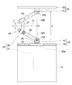
- FIG. 1 is a diagram illustrating a schematic configuration of an articulated robot according to a first embodiment of the present invention. It is the figure which abbreviate
- FIG. 1 is a diagram showing a schematic configuration of this articulated robot.
- the articulated robot 1 includes a base unit 2 and an articulated arm 3 installed on the base unit 2.
- An end effector 4 for performing work on a work body (not shown) is mounted at the tip of the articulated arm 3.
- the base unit 2 is installed on the installation surface 5 formed of a horizontal plane.
- a controller 6 that controls the operation of the articulated robot 1 is built in the base unit 2. The controller 6 may be installed outside the base unit 2.
- a plurality of (four in this embodiment) arm portions 11 to 14 are arranged in series from the proximal end side to the distal end side.
- the base unit 2 and the most proximal arm portion 11 and the adjacent arm portions 11 to 14 are connected to each other via joint portions 21 to 24 so as to be relatively displaceable from each other.
- the end effector 4 is installed on the most distal end arm portion 14.
- the arm portions 11 to 14 are connected in order from the proximal end side to the “first arm portion 11”, “second arm portion 12”, “third arm portion 13”, and “fourth arm”.
- the first joint portion 21 to the second joint portion 22, the third joint portion 23, and the fourth joint portion 21 to 24 This is referred to as a joint 24 ".
- the first joint portion 21 that connects the base unit 2 and the first arm portion 11 has the first arm portion 11 with respect to the base unit 2 around the rotation axis 7 orthogonal to the installation surface 5. This is a rotation mechanism for relative rotation.
- the first arm unit 11 is rotationally driven by a drive source 21 a provided in the base unit 2.
- the drive source 21a is, for example, a motor.
- the second joint portion 22 that connects the first arm portion 11 and the second arm portion 12 has a second axis with respect to the first arm portion 11 around the rotation axis 8 parallel to the installation surface 5.
- This is a rotation mechanism that relatively rotates the arm unit 12.
- the second arm unit 12 is rotationally driven by a drive source 22 a provided in the first arm unit 11.
- the drive source 22a is, for example, a motor.
- the third joint portion 23 that connects the second arm portion 12 and the third arm portion 13 is a linear motion mechanism that moves the third arm portion 13 in a linear direction relative to the second arm portion 12. is there.
- the movement of the third arm unit 13 is performed by a drive source 23 a provided in the second arm unit 12.
- the drive source 23a is, for example, a linear actuator.
- the second arm portion 12 and the third arm portion 13 are provided on the same axis, and when the third arm portion 13 moves closer to the base end of the second arm portion 12, the second arm portion 12
- the third arm portion 13 is housed inside the arm portion 12 and is configured such that the third arm portion 13 protrudes from the inside of the second arm portion 12 when the arm portion 12 moves away.
- the fourth joint portion 24 that connects the third arm portion 13 and the fourth arm portion 14 is a link with two degrees of freedom for rotating the fourth arm portion 14 with respect to the third arm portion 13. Actuating device.
- the link operating device includes a parallel link mechanism 30 and a posture control drive source 31 that operates the parallel link mechanism 30.
- 3 and 4 are perspective views showing only the parallel link mechanism 30, and show different states.
- the parallel link mechanism 30 is connected to the link hub 32 on the proximal end side via the three sets of link mechanisms 34 so that the posture of the link hub 33 can be changed. .
- only one set of link mechanisms 34 is shown. The number of link mechanisms 34 may be four or more.
- Each link mechanism 34 has a proximal end side link member 35, a distal end side end link member 36, and a central link member 37, and is a four-joint link mechanism composed of four rotating pairs.
- the end link members 35 and 36 on the proximal end side and the distal end side are L-shaped, and one ends thereof are rotatably connected to the link hub 32 on the proximal end side and the link hub 33 on the distal end side, respectively.
- the central link member 37 has both ends connected to the other ends of the end link members 35 and 36 on the proximal end side and the distal end side in a freely rotatable manner.
- the parallel link mechanism 30 has a structure in which two spherical link mechanisms are combined.
- the rotation pair of the proximal side link hub 32 and the proximal side end link member 35 and the central axis of each rotation pair of the proximal side end link member 35 and the central link member 37 are It intersects at the spherical link center PA (FIG. 2).
- the central axis of each rotational pair of the distal end side link hub 33 and the distal end side end link member 36 and each rotational pair of the distal end side end link member 36 and the central link member 37 are spherical surfaces on the distal end side. It intersects at the link center PB (FIG. 2).
- each rotation pair of the link hub 32 on the base end side and the end link member 35 on the base end side and the spherical link center PA on the base end side is the same, and the end link member 35 on the base end side is the same.
- the distance between each rotation pair of the central link member 37 and the spherical link center PA on the base end side is also the same.
- the distance between each rotation pair of the link hub 33 on the distal end side and the end link member 36 on the distal end side and the spherical link center PB on the distal end side is the same as each other.
- the distance between each rotation pair of the member 37 and the spherical link center PB on the tip side is also the same.
- the central axis of each rotational pair of the end link members 35 and 36 on the proximal end side and the distal end side and the central link member 37 may have a certain crossing angle ⁇ (FIG. 2) or may be parallel. Good.
- FIG. 5 is a cross-sectional view of the link hub 32 on the base end side, the end link member 35 on the base end side, and the like.
- FIG. 5 shows the relationship between the center axis O1 of each rotation pair of the base end side link hub 32 and the base end side end link member 35 and the base end side spherical link center PA.
- the positional relationship between the distal end side link hub 33 and the distal end side end link member 36 is also the same as that in FIG. 5 (not shown).
- the center axis O1 of each rotation pair of the base end side link hub 32 and the base end side end link member 35, and each rotation of the base end side end link member 35 and the central link member 37 is 90 °, the angle ⁇ may be other than 90 °.
- the three sets of link mechanisms 34 have the same geometric shape.
- the geometrically identical shape is represented by a geometric model in which each link member 35, 36, 37 is represented by a straight line, that is, each rotational pair and a straight line connecting these rotational pairs.
- a model says that the base end side part and front end side part with respect to the center part of the center link member 37 are symmetrical shapes.
- FIG. 6 is a diagram representing a set of link mechanisms 34 by straight lines.
- the parallel link mechanism 30 of this embodiment is a rotationally symmetric type, and includes a proximal end side link hub 32 and a proximal end side end link member 35, a distal end side link hub 33 and a distal end side end link member 36.
- the positional relationship is such that the positional relationship is rotationally symmetric with respect to the center line C of the central link member 37.
- the central part of each central link member 37 is located on a common track circle D.
- the link hub 32 on the proximal end side, the link hub 33 on the distal end side, and the three sets of link mechanisms 34 allow the link hub 33 on the distal end side to rotate about two orthogonal axes with respect to the link hub 32 on the proximal end side.
- the degree mechanism is configured.
- the position of the link hub 33 on the distal end side with respect to the link hub 32 on the proximal end side is a mechanism whose posture can be freely changed with two degrees of freedom.
- this two-degree-of-freedom mechanism is compact, the movable range of the link hub 33 on the distal end side with respect to the link hub 32 on the proximal end side can be widened.
- each rotation pair of the proximal and distal link hubs 32 and 33 and the proximal and distal end link members 35 and 36 passes through the spherical link centers PA and PB on the proximal and distal ends.
- the straight lines intersecting the central axis O1 (FIG. 5) at right angles are the central axes QA and QB of the link hubs 32 and 33 on the proximal end side and the distal end side
- the maximum value of the bending angle ⁇ (FIG. 6) with respect to the center axis QB of the link hub 33 can be about ⁇ 90 °.
- the turning angle ⁇ (FIG. 6) of the distal end side link hub 33 with respect to the proximal end side link hub 32 can be set in a range of 0 ° to 360 °.
- the bending angle ⁇ is a vertical angle at which the central axis QB of the distal link hub 33 is inclined with respect to the central axis QA of the proximal link hub 32.
- the turning angle ⁇ is a horizontal angle at which the central axis QB of the distal link hub 33 is inclined with respect to the central axis QA of the proximal link hub 32.
- the posture change of the distal end side link hub 33 with respect to the proximal end side link hub 32 is performed with an intersection O between the central axis QA of the proximal end side link hub 32 and the central axis QB of the distal end side link hub 33 as a rotation center.
- Is called. 3 shows a state in which the central axis QA of the link hub 32 on the proximal end side and the central axis QB of the link hub 33 on the distal end side are on the same line
- FIG. 4 shows the central axis QA of the link hub 32 on the proximal end side.
- a state in which the central axis QB of the link hub 33 on the distal end side takes an arbitrary operating angle is shown. Even if the posture changes, the distance L (FIG. 6) between the spherical link centers PA and PB on the proximal end side and the distal end side does not change.
- the link hub 32 on the base end side includes a base end member 40 fixed to the third arm portion 13 and three rotations provided integrally with the base end member 40.
- the base end member 40 has a circular through hole 40a at the center, and three rotary shaft coupling members 41 are arranged at equal intervals in the circumferential direction around the through hole 40a.
- the center of the through hole 40a is located on the central axis QA of the link hub 32 on the proximal end side.
- a rotating shaft 42 whose shaft center intersects the central axis QA of the link hub 32 on the proximal end side is rotatably connected to each rotating shaft connecting member 41.
- One end of an end link member 35 on the base end side is connected to the rotating shaft 42.
- the rotary shaft 42 is rotatably supported by the rotary shaft connecting member 41 via two bearings 43.
- the bearing 43 is a ball bearing such as a deep groove ball bearing or an angular ball bearing. These bearings 43 are fitted into an inner diameter hole 44 provided in the rotary shaft connecting member 41 and are fixed by a method such as press-fitting, adhesion, or caulking. The same applies to the types and installation methods of the bearings provided in other rotating pairs.
- the rotating shaft 42 is coupled with one end of an end link member 35 on the base end side and a fan-shaped bevel gear 45 described later so as to rotate integrally with the rotating shaft 42.
- a notch 46 is formed at one end of the base end side end link member 35, and both side portions of the notch 46 constitute inner and outer rotary shaft support portions 47 and 48.
- a rotary shaft connecting member 41 is disposed between the inner and outer rotary shaft support portions 47 and 48.
- the bevel gear 45 is disposed in contact with the inner surface of the inner rotary shaft support 47.
- the rotation shaft 42 includes a through hole formed in the bevel gear 45, a through hole formed in the inner rotation shaft support portion 47, an inner ring of the bearing 43, and a through hole formed in the outer rotation shaft support portion 48.
- the nut 50 is screwed into the threaded portion 42 b at the tip of the rotating shaft 42. Thereby, the head 42a of the rotating shaft 42 and the nut 50 sandwich the bevel gear 45, the inner and outer rotating shaft support portions 47 and 48, and the inner ring of the bearing 43, and are coupled to each other.
- Spacers 51 and 52 are interposed between the inner and outer rotary shaft support portions 47 and 48 and the bearing 43, and a preload is applied to the bearing 43 by screwing the nut 50.
- the rotating shaft 55 is coupled to the other end of the end link member 35 on the base end side.
- the rotary shaft 55 is rotatably connected to one end of the central link member 37 via two bearings 53.
- a notch 56 is formed at the other end of the base end side end link member 35, and both side portions of the notch 56 constitute inner and outer rotary shaft support portions 57 and 58.
- One end of the central link member 37 is disposed between the inner and outer rotary shaft support portions 57 and 58.
- the rotating shaft 55 is inserted from the outside through the through hole formed in the outer rotating shaft support portion 58, the inner ring of the bearing 53, and the through hole formed in the inner rotating shaft support portion 57 in this order.
- a nut 60 is screwed onto the screw portion 55b.
- the inner and outer rotary shaft support portions 57 and 58 and the inner ring of the bearing 53 are held between the head portion 55a of the rotary shaft 55 and the nut 60 and are coupled to each other.
- Spacers 61 and 62 are interposed between the inner and outer rotary shaft support portions 57 and 58 and the bearing 53, and a preload is applied to the bearing 53 by screwing the nut 60.
- the link hub 33 on the distal end side is provided with a distal end member 70 fixed to the fourth arm portion 14, and 3 provided on the inner surface of the distal end member 70 at equal intervals in the circumferential direction.
- Individual rotating shaft connecting members 71 The center of the circumference where each rotary shaft connecting member 71 is arranged is located on the central axis QB of the link hub 33 on the distal end side.
- a rotary shaft 73 is rotatably connected to each rotary shaft connecting member 71. The axis of the rotation shaft 73 intersects the center axis QB of the link hub 33 on the distal end side.
- One end of the end link member 36 on the front end side is connected to the rotation shaft 73 of the link hub 33 on the front end side.
- a rotating shaft 75 is connected to the other end of the end link member 36 on the front end side.
- the rotating shaft 75 is rotatably connected to the other end of the central link member 37.
- the rotary shaft 73 of the link hub 33 on the distal end side and the rotary shaft 75 of the central link member 37 are respectively connected to the rotary shaft connecting member 71 via two bearings (not shown) in the same manner as the rotary shafts 42 and 55 described above.
- the other end of the center link member 37 is rotatably connected to each other.
- the attitude control drive source 31 for operating the parallel link mechanism 30 is installed on the base end member 40 and is arranged inside the third arm portion 13.
- the number of posture control drive sources 31 is three, which is the same as the number of link mechanisms 34.
- the attitude control drive source 31 is a rotary actuator.
- the same number of attitude control drive sources 31 as the link mechanisms 34 are provided. However, as long as at least two of the three sets of link mechanisms 34 are provided with the attitude control drive sources 31.
- the posture of the distal end side link hub 33 with respect to the proximal end side link hub 32 can be determined.
- 4th joint part 24 consisting of a link actuating device operates parallel link mechanism 30 by rotationally driving each attitude control drive source 31. Specifically, when the attitude control drive source 31 is rotationally driven, the rotation is transmitted to the rotary shaft 42 via a pair of bevel gears 76 and 45, and the proximal end side link member with respect to the proximal end side link hub 32. The angle of 35 changes. As a result, the position and posture of the distal end side link hub 33 relative to the proximal end side link hub 32 are determined. Here, the angle of the end link member 35 on the base end side is changed using the bevel gears 76 and 45, but other mechanisms (for example, a spur gear or a worm mechanism) may be used.
- each attitude control drive source 31 is provided with torque detection means 78 for detecting the torque applied to the attitude control drive source 31.
- the detection signal of the torque detection means 78 is transmitted to the load estimation means 79 in the controller 6.
- the load estimating means 79 estimates the load acting on the distal end side link hub 33 from the detection results of the torque detecting means 78.
- the tip arm rotation mechanism 80 is provided in the fourth arm portion 14, and the end effector 4 is supported via the tip rotation mechanism 80.
- the tip rotation mechanism 80 includes a rotation drive source 80a such as a motor, and an end effector installation member 80b attached to the rotation shaft of the rotation drive source 80a.
- the end effector 4 is fixed to the end effector installation member 80b.
- the end effector 4 for example, a hand, a welding machine, a coating machine, or the like is used, but the end effector 4 is not limited to these.
- This multi-joint robot 1 has one degree of freedom of the first joint portion 21 composed of a rotation mechanism, one degree of freedom of the second joint portion 22 composed of a rotation mechanism, and one of the third joint portion 23 composed of a linear motion mechanism.
- the configuration is a total of 6 degrees of freedom, including a degree of freedom, 2 degrees of freedom of the fourth joint portion 24 formed of a link actuating device, and 1 degree of freedom of the tip rotation mechanism 80 provided in the fourth arm portion 14. With a 6-degree-of-freedom configuration, it is possible to approximate the movement of a human hand.
- a link actuator for one of the plurality of joints 21 to 24 by using a link actuator for one of the plurality of joints 21 to 24, a smooth operation having no singular point is possible within the operation range of 90 ° of bending angle and 360 ° of turning.
- the fine motion is, for example, a motion that moves around a human wrist joint, such as a character writing motion or a motion using a snap.
- detailed operations are not limited to these operations.
- the joint portion 24 can be made compact while having two degrees of freedom of rotation.
- Torque detection means 78 for detecting the torque applied to each posture control drive source 31 and load estimation means 79 for estimating the load acting on the distal end side link hub 33 from the detection result of the torque detection means 78 are provided. Yes. For this reason, when an abnormal load is applied to the multi-joint robot 1, for example, when it collides with a person or an object, this can be detected. For this reason, when an abnormal load is applied, it is possible to take an avoidance operation such as stopping the operation, which is safe.
- the torque detection means 78 in the attitude control drive source 31 it is possible to estimate the load acting on the link hub 33 on the distal end side without providing a load detection sensor separately. As a result, the articulated robot 1 can be made compact and cost reduced. In addition, since there is no singular point and the structure can be moved smoothly in all directions within the operating range of the fourth joint portion 24 composed of the link operating device, when loads are applied to the link hub 33 on the distal end side from various directions. However, torque is reliably transmitted to the attitude control drive source 31. Thereby, an accurate load can be estimated.
- the fourth joint portion 24 corresponding to the wrist joint is a two-degree-of-freedom link actuating device capable of operating close to the wrist joint. It is composed. For this reason, it becomes easier to imagine the relationship between the movement of each joint portion 21 to 24 and the movement of the end effector 4, and the operability is good.
- the fourth joint portion 24 formed of the link actuator is disposed near the tip of the multi-joint arm 3, the load acting on the link actuator is small, and higher speed and finer operation is possible.
- distal end rotation mechanism 80 that may twist the cable is arranged on the distal end side with respect to the fourth joint portion 24 composed of the link actuating device and the third joint portion 23 composed of the linear motion mechanism, the link operation is performed. Wiring of devices, linear motion mechanisms, etc. is easy.
- the third arm portion 13 is housed inside the second arm portion 12. For this reason, when the articulated robot 1 is not used, it can be made compact and the storage space can be narrow. Further, since the movable range of the entire articulated robot 1, particularly the movable range of the articulated arm 3 between the base unit 2 and the end effector 4 can be minimized, the occupied space can be reduced.
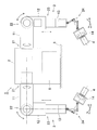
- FIG. 7 shows a second embodiment.
- the multi-joint robot 1 of the second embodiment is different from the first embodiment of FIG. 1 in the third joint portion 23 formed of a linear motion mechanism.
- the third arm unit 13 moves along the linear stage 23 b installed on the side surface of the second arm unit 12.
- the driving of the third arm unit 13 is performed by a driving source 23 c provided in the second arm unit 12.
- the drive source 23c is, for example, a linear actuator.
- Other configurations are the same as those of the articulated robot 1 of the first embodiment shown in FIG.
- FIG. 8 further shows a third embodiment.
- the articulated robot 1 of the third embodiment two articulated arms 3 are installed in one base unit 2.
- the first arm portions 11 of the two articulated arms 3 are installed on side surfaces of the base unit 2 that are symmetrical to each other.
- the configuration of each articulated arm 3 is the same as the articulated arm 3 of the articulated robot 1 of the first embodiment shown in FIG.
- FIG. 9 further shows a fourth embodiment.
- the second joint portion 22 of the articulated arm 3 is replaced with a rotation mechanism of the articulated robot 1 of the first embodiment of FIG.
- the structure of the other joint parts 21, 23, and 24 is the same as that of the articulated robot of the first embodiment shown in FIG. Since the second joint portion 22 has two degrees of freedom, the multi-joint arm 3 itself has a configuration of six degrees of freedom.
- the tip arm rotation mechanism (not shown) is provided on the fourth arm portion 14, the entire articulated robot 1 has a configuration of 7 degrees of freedom.
Abstract
This articulated robot (1) has a base unit (2) and an articulated arm (3). In the articulated arm (3), a plurality of arm portions (11-14) are aligned in series from a base end side to a tip side, and the base unit (2) and the arm portion (11) furthest to the base end side, as well as the adjoining arm portions (11-14) themselves, are connected to each other via joint portions (21-24) so as to be displaceable relative to each other. An end effector (4) is mounted to the arm portion (14) furthest to the tip side. At least one joint portion (24) comprises a link actuation device that rotates the arm portions (13, 14) on both sides relative to each other around two orthogonal axes, and at least one joint portion (23) comprises a linear motion mechanism that moves the arm portions (12, 13) on both sides relative to each other in a linear direction.
Description
この出願は、2015年2月13日出願の特願2015-025926の優先権を主張するものであり、その全体を参照により本願の一部をなすものとして引用する。
This application claims the priority of Japanese Patent Application No. 2015-025926 filed on February 13, 2015, the entire contents of which are incorporated herein by reference.
この発明は、医療機器や産業機器のような高速、高精度、および広範な作動範囲を必要とする機器や人と共存するロボット等に用いられるリンク作動装置を用いた6自由度以上の多関節ロボットに関する。
The present invention is a multi-joint articulation with 6 degrees of freedom or more using a link actuating device used in a device such as a medical device or an industrial device that requires high speed, high accuracy, and a wide working range, or a robot coexisting with a person. Regarding robots.
医療機器や産業機器のような高速、高精度、および広範な作動範囲を必要とする機器や人と共存するロボット等に用いられる多関節ロボットが、特許文献1、2に提案されている。特許文献1の多関節ロボットは、回転1自由度の機構を組み合わせて構成されている。特許文献2の多関節ロボットは、回転2自由度のリンク作動装置が用いられている。
Patent Documents 1 and 2 propose articulated robots used for devices such as medical devices and industrial devices that require high speed, high accuracy, and a wide operating range, and robots that coexist with humans. The articulated robot of Patent Document 1 is configured by combining a mechanism with one degree of freedom of rotation. The articulated robot of Patent Document 2 uses a link actuator with two degrees of freedom of rotation.
特許文献1の多関節ロボットは、すべて回転1自由度の関節部の組合せで構成されている。そのため、例えば多関節ロボットが人や物に衝突した場合、その衝突を検知し難い方向があり、安全面で問題がある。また、先端に搭載するエンドエフェクタの姿勢を少し変更するだけでも複数のモータを駆動する必要があり、きめ細かい作業が出来ないといった問題がある。さらに、制御上の問題として、エンドエフェクタの1つの姿勢に対して複数の解が存在する場合があり、動作を確定できない可能性がある。操作上の問題としては、教示を行う際に各軸を動かしても先端がどのような方向に移動するかイメージし難いため、操作を行うには知識や経験が必要である。
The articulated robot of Patent Document 1 is composed of a combination of joints with one degree of freedom of rotation. Therefore, for example, when an articulated robot collides with a person or an object, there is a direction in which the collision is difficult to detect, and there is a problem in terms of safety. In addition, it is necessary to drive a plurality of motors even by slightly changing the attitude of the end effector mounted on the tip, and there is a problem that detailed work cannot be performed. Furthermore, as a control problem, there may be a plurality of solutions for one posture of the end effector, and there is a possibility that the operation cannot be determined. As an operation problem, it is difficult to imagine in which direction the tip moves even if each axis is moved during teaching, so knowledge and experience are required to perform the operation.
特許文献2の多関節ロボットは、滑らかな回転2自由度動作が可能なリンク作動装置を設けたことにより、安全面の問題は解決できる。しかしながら、リンク作動装置の基端側のリンクハブの中心軸上にエンドエフェクタ(例えばハンド)を動かす場合、リンク作動装置の姿勢と肘関節の双方を動かして調整する必要がある。そのため、操作を行うには知識や経験が必要である。また、リンク作動装置の負荷が大きく、きめ細かい作業が出来ないことが予想される。
The articulated robot of Patent Document 2 can solve the safety problem by providing a link actuating device capable of smooth two-degree-of-freedom rotation. However, when an end effector (for example, a hand) is moved on the central axis of the link hub on the proximal side of the link actuator, it is necessary to adjust both the posture of the link actuator and the elbow joint. Therefore, knowledge and experience are required to perform the operation. In addition, it is expected that the load of the link operating device is large and detailed work cannot be performed.
この発明の目的は、関節部がコンパクトで、きめ細かい素早い動作が可能で、動作の安全性が高く、人と共存する作業現場で使用するのに適したリンク作動装置を用いた多関節ロボットを提供することである。
An object of the present invention is to provide a multi-joint robot using a link actuator suitable for use in a work site where the joint portion is compact, fine and quick operation is possible, operation safety is high, and coexist with humans. It is to be.
この発明のリンク作動装置を用いた多関節ロボットは、ベースユニットと、このベースユニットに設置された多関節アームとを有し、この多関節アームは、基端側から先端側へ複数のアーム部が直列に並び、前記ベースユニットと最も基端側のアーム部、および隣り合うアーム部同士がそれぞれ関節部を介して互いに相対変位可能に連結され、最も先端側のアーム部に搭載されたエンドエフェクタを用いて作業を行う6自由度以上の多関節ロボットであって、
前記複数の関節部のうちの少なくとも1つの関節部は、両側の前記アーム部同士を互いに直交2軸周りに相対回転させるリンク作動装置からなり、かつ残りの関節部のうちの少なくとも1つの関節部は、両側の前記アーム部同士を互いに直線方向に相対移動させる直動機構からなり、
前記リンク作動装置は、両側の前記アーム部のうちの基端側のアーム部に固定された基端側のリンクハブに対し先端側のアーム部に固定された先端側のリンクハブを、3組以上のリンク機構を介して姿勢を変更可能に連結し、前記各リンク機構は、それぞれ前記基端側のリンクハブおよび前記先端側のリンクハブに一端が回転可能に連結された基端側および先端側の端部リンク部材と、これら基端側および先端側の端部リンク部材の他端に両端がそれぞれ回転可能に連結された中央リンク部材とを有し、前記3組以上のリンク機構のうちの2組以上のリンク機構に前記基端側のリンクハブに対する前記先端側のリンクハブの姿勢を任意に変更させる姿勢制御用駆動源が設けられている。 An articulated robot using the link actuator of the present invention has a base unit and an articulated arm installed on the base unit, and the articulated arm has a plurality of arm portions from the base end side to the distal end side. Are arranged in series, and the base unit, the most proximal arm part, and the adjacent arm parts are connected to each other via a joint part so as to be relatively displaceable from each other, and are mounted on the most distal arm part. An articulated robot with 6 degrees of freedom or more that works using
At least one joint portion of the plurality of joint portions includes a link actuator that relatively rotates the arm portions on both sides around two orthogonal axes, and at least one joint portion of the remaining joint portions. Consists of a linear motion mechanism that relatively moves the arms on both sides in a linear direction.
The link actuating device comprises three sets of link hubs on the distal end side fixed to the arm portion on the distal end side with respect to the link hub on the proximal end side fixed to the arm portion on the proximal end side among the arm portions on both sides. The above-mentioned link mechanisms are connected so that their postures can be changed, and the respective link mechanisms are respectively connected to the base end side link hub and the front end side link hub so that one end is rotatably connected to the base end side and the front end. Side end link members, and central link members whose both ends are rotatably connected to the other ends of the base end side and distal end side end link members, respectively, of the three or more sets of link mechanisms The two or more sets of link mechanisms are provided with a posture control drive source that arbitrarily changes the posture of the distal end side link hub with respect to the proximal end side link hub.
リンク作動装置は、基端側のリンクハブと、先端側のリンクハブと、3組以上のリンク機構とで、基端側のリンクハブに対し先端側のリンクハブが直交2軸周りに回転自在な2自由度機構を構成する。この2自由度機構は、コンパクトでありながら、先端側のリンクハブの可動範囲を広くとれる。例えば、基端側のリンクハブの中心軸と先端側のリンクハブの中心軸の折れ角の最大値は約±90°であり、基端側のリンクハブに対する先端側のリンクハブの旋回角を0°~360°の範囲に設定できる。
The link actuating device is composed of a link hub on the base end side, a link hub on the front end side, and three or more sets of link mechanisms. The link hub on the front end side is rotatable about two orthogonal axes with respect to the link hub on the base end side. A two-degree-of-freedom mechanism. Although this two-degree-of-freedom mechanism is compact, the movable range of the link hub on the distal end side can be widened. For example, the maximum bending angle between the central axis of the link hub on the proximal end side and the central axis of the link hub on the distal end side is about ± 90 °, and the swivel angle of the link hub on the distal end side with respect to the link hub on the proximal end side is It can be set in the range of 0 ° to 360 °.
複数の関節部のうち少なくとも1つの関節部に上記リンク作動装置を用いることで、折れ角90°、旋回角360°の作動範囲において特異点を持たないスムーズな動作が可能となり、きめ細かい動作を実現できる。また、残りの関節部のうちの少なくとも1つの関節部に直動機構を用いることで、直進方向の操作を1つのアクチュエータの操作で行うことができるので、知識に乏しく経験が浅くても簡単に操作することができる。
By using the link actuating device for at least one of the joints, smooth operation with no singularity is possible in the operating range of the folding angle of 90 ° and turning angle of 360 °, and fine operation is realized. it can. Also, by using a linear motion mechanism for at least one of the remaining joints, it is possible to perform a straight-ahead operation by operating one actuator, so it is easy even if you have little knowledge and little experience. Can be operated.
この発明において、前記姿勢制御用駆動源が回転力を発生させるロータリアクチュエータである場合、各姿勢制御用駆動源にこの姿勢制御用駆動源にかかるトルクを検出するトルク検出手段を設け、このトルク検出手段の検出結果から前記先端側のリンクハブに作用する荷重を推定する荷重推定手段を設けても良い。
In the present invention, when the attitude control drive source is a rotary actuator that generates a rotational force, each attitude control drive source is provided with torque detection means for detecting the torque applied to the attitude control drive source. You may provide the load estimation means which estimates the load which acts on the link hub of the said front end from the detection result of a means.
これにより、多関節ロボットに異常な負荷がかかった場合、例えば人や物に衝突した場合にこれを検知することができる。このため、異常な負荷がかかったときに、動作を停止する等の回避動作をとることができ、安全である。
Thus, when an abnormal load is applied to the articulated robot, for example, when it collides with a person or an object, this can be detected. For this reason, when an abnormal load is applied, an avoidance operation such as stopping the operation can be performed, which is safe.
姿勢制御用駆動源にトルク検出手段を設けることで、荷重検出用のセンサを別に設けることなく、先端側のリンクハブに作用する荷重を推定することができ、多関節ロボットのコンパクト化やコスト低減に繋がる。また、リンク作動装置の作動範囲内において、特異点がなく全方向にスムーズに動かせる構成であるため、先端側のリンクハブに様々な方向から荷重が作用した場合でも姿勢制御用駆動源に確実にトルクが伝達され、正確な荷重を推定することができる。
By providing torque detection means in the attitude control drive source, the load acting on the link hub on the tip side can be estimated without providing a separate load detection sensor, making the articulated robot more compact and reducing cost. It leads to. In addition, there is no singular point within the operating range of the link actuator, and it can be moved smoothly in all directions, so even if a load is applied to the link hub on the tip side from various directions, the posture control drive source can be reliably Torque is transmitted and an accurate load can be estimated.
この発明において、前記直動機構は、両側の前記アーム部を互いに前記直線方向の一方向に相対移動させるとき、いずれか一方のアーム部がもう一方のアーム部の内部に収納される構成であると良い。この構成であると、多関節ロボットを使用しないときにコンパクトにすることができ、保管スペースが狭くて済む。また、多関節ロボット全体の可動範囲、特にベースユニットとエンドエフェクタの間の多関節アームの可動範囲を最小限にできるので、占有スペースを狭くできる。
In this invention, the linear motion mechanism is configured such that when the arm portions on both sides are moved relative to each other in one direction of the linear direction, either one of the arm portions is housed inside the other arm portion. And good. With this configuration, when the articulated robot is not used, it can be made compact, and a storage space can be reduced. In addition, since the movable range of the entire articulated robot, particularly the movable range of the articulated arm between the base unit and the end effector can be minimized, the occupied space can be reduced.
この発明において、前記ベースユニットと最も基端側の前記アーム部とを連結する関節部は、前記ベースユニットの設置面に対して直交する回転軸回りに両側の前記ベースユニットおよび記アーム部を相対回転させる回転機構からなり、最も基端側の前記アーム部と基端側から2番目の前記アーム部とを連結する関節部は、前記ベースユニットの設置面と平行な回転軸回りに両側の前記各アーム部を相対回転させる回転機構からなり、基端側から2番目の前記アーム部と基端側から3番目の前記アーム部とを連結する関節部は、両側の前記アーム部同士を互いに直線方向に相対移動させる前記直動機構からなり、前記基端側から3番目のアーム部と基端側から4番目のアーム部とを連結する関節部は、両側の前記アーム部同士を互いに直交2軸周りに相対回転させる前記リンク作動装置からなり、基端側から4番目の前記アーム部と前記エンドエフェクタとを連結する関節部は、両側の前記各アーム部を相対回転させる回転機構からなると良い。
In this invention, the joint portion that connects the base unit and the arm portion on the most proximal side has the base unit and the arm portion on both sides relative to each other around a rotation axis orthogonal to the installation surface of the base unit. The joint portion, which comprises a rotating mechanism that rotates, and connects the arm portion closest to the base end side and the second arm portion from the base end side, is arranged on both sides around a rotation axis parallel to the installation surface of the base unit. The joint portion that connects the second arm portion from the base end side and the third arm portion from the base end side is a linear mechanism that connects the arm portions on both sides to each other. A joint mechanism that connects the third arm portion from the base end side and the fourth arm portion from the base end side, and the arm portions on both sides are orthogonal to each other. It is preferable that the joint unit that connects the fourth arm part from the base end side and the end effector includes a rotation mechanism that relatively rotates the arm parts on both sides. .
この構成とすると、この多関節ロボットの多関節アームを人間の腕と見なした場合、手首関節に相当する第4の関節部を、手首関節に近い動作が可能な回転2自由度のリンク作動装置で構成している。そのため、各関節部の動きとエンドエフェクタの動きとの関係をイメージし易くなり、操作性が良い。また、人の腕における手首関節に相当する多関節アームの先端付近の関節部にリンク作動装置が配置されているので、リンク作動装置に作用する負荷が小さく、より高速できめ細かい動作が可能である。さらに、多関節アームにおいてリンク作動装置、直動機構等よりも先端側にケーブルを捩れさせる可能性のある回転機構が配置されているので、リンク作動装置や直動機構等の配線の取り回しが容易である。
With this configuration, when the multi-joint arm of this multi-joint robot is regarded as a human arm, the fourth joint corresponding to the wrist joint can be operated close to the wrist joint so that the link can operate with two degrees of freedom. It consists of devices. Therefore, it becomes easy to imagine the relationship between the movement of each joint and the movement of the end effector, and the operability is good. In addition, since the link actuator is arranged at the joint portion near the tip of the multi-joint arm corresponding to the wrist joint in the human arm, the load acting on the link actuator is small, and higher speed and detailed operation is possible. . In addition, since the rotation mechanism that can twist the cable is arranged on the tip side of the multi-joint arm relative to the link actuator, linear motion mechanism, etc., wiring of the link actuator, linear motion mechanism, etc. is easy It is.
この発明において、1つの前記ベースユニットに前記多関節アームを2つ設置すると良い。これにより、人が両手で行うような作業が可能となる。
In this invention, it is preferable to install two articulated arms on one base unit. As a result, it is possible to perform an operation that a person performs with both hands.
前記2つの多関節アームは、前記ベースユニットの互いに対称となる面に最も基端側の前記アーム部が設置されていると良い。この構成とすることで、人と同じような双腕型のロボットの形状となり、人と同じような作業を行うことができる。また、多関節ロボットが機能不全となった場合、多関節ロボットを撤去した跡のスペースに人が入って代替して作業を行うことができるので、生産性を大幅に下げることを防止できる。
In the two multi-joint arms, it is preferable that the arm portion on the most proximal side is installed on the surfaces of the base unit that are symmetrical to each other. By adopting this configuration, the shape of a double-armed robot similar to that of a person is obtained, and work similar to that of a person can be performed. Further, when the articulated robot becomes malfunctioning, it is possible to perform work by replacing a person who has entered the space where the articulated robot has been removed.
請求の範囲および/または明細書および/または図面に開示された少なくとも2つの構成のどのような組合せも、この発明に含まれる。特に、請求の範囲の各請求項の2つ以上のどのような組合せも、この発明に含まれる。
Any combination of at least two configurations disclosed in the claims and / or the specification and / or the drawings is included in the present invention. In particular, any combination of two or more of each claim in the claims is included in the invention.
この発明は、添付の図面を参考にした以下の好適な実施形態の説明からより明瞭に理解されるであろう。しかしながら、実施形態および図面は単なる図示および説明のためのものであり、この発明の範囲を定めるために利用されるべきものではない。この発明の範囲は添付の請求の範囲によって定まる。添付図面において、複数の図面における同一の部品番号は、同一または相当部分を示す。
この発明の第1実施形態にかかる多関節ロボットの概略構成を示す図である。
同多関節ロボットのリンク作動装置の一部を省略した図である。
同リンク作動装置のパラレルリンク機構の一状態の斜視図である。
同パラレルリンク機構の異なる状態の斜視図である。
同パラレルリンク機構の基端側のリンクハブ、基端側の端部リンク部材等の断面図である。
同パラレルリンク機構の1つのリンク機構を直線で表現した図である。
この発明の第2実施形態にかかる多関節ロボットの概略構成を示す図である。
この発明の第3実施形態にかかる多関節ロボットの概略構成を示す図である。
この発明の第4実施形態にかかる多関節ロボットの概略構成を示す図である。
The present invention will be more clearly understood from the following description of preferred embodiments with reference to the accompanying drawings. However, the embodiments and drawings are for illustration and description only and should not be used to define the scope of the present invention. The scope of the invention is defined by the appended claims. In the accompanying drawings, the same part numbers in a plurality of drawings indicate the same or corresponding parts.
1 is a diagram illustrating a schematic configuration of an articulated robot according to a first embodiment of the present invention. It is the figure which abbreviate | omitted a part of link operating device of the same articulated robot. It is a perspective view of one state of the parallel link mechanism of the link actuator. It is a perspective view of a different state of the parallel link mechanism. It is sectional drawing of the link hub of the base end side of the parallel link mechanism, the edge part link member of a base end side, etc. It is the figure which expressed one link mechanism of the parallel link mechanism with a straight line. It is a figure which shows schematic structure of the articulated robot concerning 2nd Embodiment of this invention. It is a figure which shows schematic structure of the articulated robot concerning 3rd Embodiment of this invention. It is a figure which shows schematic structure of the articulated robot concerning 4th Embodiment of this invention.
この発明の第1実施形態に係るリンク作動装置を用いた多関節ロボットを図1~図6と共に説明する。図1はこの多関節ロボットの概略構成を示す図である。多関節ロボット1は、ベースユニット2と、このベースユニット2に設置された多関節アーム3とを有している。多関節アーム3の先端に、被作業体(図示せず)に対して作業を行うエンドエフェクタ4が搭載されている。この実施形態では、ベースユニット2は、水平面からなる設置面5に設置されている。ベースユニット2内には、この多関節ロボット1の動作を制御するコントローラ6が内蔵されている。コントローラ6は、ベースユニット2の外部に設置しても良い。
An articulated robot using the link actuator according to the first embodiment of the present invention will be described with reference to FIGS. FIG. 1 is a diagram showing a schematic configuration of this articulated robot. The articulated robot 1 includes a base unit 2 and an articulated arm 3 installed on the base unit 2. An end effector 4 for performing work on a work body (not shown) is mounted at the tip of the articulated arm 3. In this embodiment, the base unit 2 is installed on the installation surface 5 formed of a horizontal plane. A controller 6 that controls the operation of the articulated robot 1 is built in the base unit 2. The controller 6 may be installed outside the base unit 2.
多関節アーム3は、基端側から先端側へ複数(この実施形態では4つ)のアーム部11~14が直列に並んでいる。前記ベースユニット2と最も基端側のアーム部11、および隣り合うアーム部11~14同士が、それぞれ関節部21~24を介して互いに相対変位可能に連結されている。エンドエフェクタ4は、最も先端側のアーム部14に設置されている。以下の説明では、各アーム部11~14を、基端側から順に「第1のアーム部11」、「第2のアーム部12」、「第3のアーム部13」および「第4のアーム部14」と称し、各関節部21~24を、基端側から順に「第1の関節部21」、「第2の関節部22」、「第3の関節部23」および「第4の関節部24」と称する。
In the multi-joint arm 3, a plurality of (four in this embodiment) arm portions 11 to 14 are arranged in series from the proximal end side to the distal end side. The base unit 2 and the most proximal arm portion 11 and the adjacent arm portions 11 to 14 are connected to each other via joint portions 21 to 24 so as to be relatively displaceable from each other. The end effector 4 is installed on the most distal end arm portion 14. In the following description, the arm portions 11 to 14 are connected in order from the proximal end side to the “first arm portion 11”, “second arm portion 12”, “third arm portion 13”, and “fourth arm”. The first joint portion 21 to the second joint portion 22, the third joint portion 23, and the fourth joint portion 21 to 24. This is referred to as a joint 24 ".
ベースユニット2と第1のアーム部11とを連結する第1の関節部21は、前記設置面5に対して直交する回転軸7回りに、ベースユニット2に対して第1のアーム部11を相対回転させる回転機構である。第1のアーム部11の回転駆動は、ベースユニット2に設けられた駆動源21aにより行われる。駆動源21aは、例えば、モータである。
The first joint portion 21 that connects the base unit 2 and the first arm portion 11 has the first arm portion 11 with respect to the base unit 2 around the rotation axis 7 orthogonal to the installation surface 5. This is a rotation mechanism for relative rotation. The first arm unit 11 is rotationally driven by a drive source 21 a provided in the base unit 2. The drive source 21a is, for example, a motor.
第1のアーム部11と第2のアーム部12とを連結する第2の関節部22は、前記設置面5と平行な回転軸8回りに、第1のアーム部11に対して第2のアーム部12を相対回転させる回転機構である。第2のアーム部12の回転駆動は、第1のアーム部11に設けられた駆動源22aにより行われる。駆動源22aは、例えば、モータである。
The second joint portion 22 that connects the first arm portion 11 and the second arm portion 12 has a second axis with respect to the first arm portion 11 around the rotation axis 8 parallel to the installation surface 5. This is a rotation mechanism that relatively rotates the arm unit 12. The second arm unit 12 is rotationally driven by a drive source 22 a provided in the first arm unit 11. The drive source 22a is, for example, a motor.
第2のアーム部12と第3のアーム部13とを連結する第3の関節部23は、第2のアーム部12に対して第3のアーム部13を直線方向に移動させる直動機構である。第3のアーム部13の移動は、第2のアーム部12に設けられた駆動源23aにより行われる。駆動源23aは、例えば、リニアアクチュエータである。第2のアーム部12と第3のアーム部13とは同軸上に設けられており、第2のアーム部12の基端に対し第3のアーム部13が近づく側に移動すると、第2のアーム部12の内部に第3のアーム部13が収納され、遠ざかると、第2のアーム部12の内部から第3のアーム部13が突出するように構成されている。
The third joint portion 23 that connects the second arm portion 12 and the third arm portion 13 is a linear motion mechanism that moves the third arm portion 13 in a linear direction relative to the second arm portion 12. is there. The movement of the third arm unit 13 is performed by a drive source 23 a provided in the second arm unit 12. The drive source 23a is, for example, a linear actuator. The second arm portion 12 and the third arm portion 13 are provided on the same axis, and when the third arm portion 13 moves closer to the base end of the second arm portion 12, the second arm portion 12 The third arm portion 13 is housed inside the arm portion 12 and is configured such that the third arm portion 13 protrudes from the inside of the second arm portion 12 when the arm portion 12 moves away.
第3のアーム部13と第4のアーム部14とを連結する第4の関節部24は、第3のアーム部13に対して第4のアーム部14を姿勢変更させる回転2自由度のリンク作動装置である。
The fourth joint portion 24 that connects the third arm portion 13 and the fourth arm portion 14 is a link with two degrees of freedom for rotating the fourth arm portion 14 with respect to the third arm portion 13. Actuating device.
第4の関節部24であるリンク作動装置について説明する。図2に示すように、リンク作動装置は、パラレルリンク機構30と、このパラレルリンク機構30を作動させる姿勢制御用駆動源31とを有している。図3および図4は、パラレルリンク機構30のみを示す斜視図であり、互いに異なる状態を示している。これら図2~図4に示すように、パラレルリンク機構30は、基端側のリンクハブ32に対し先端側のリンクハブ33を3組のリンク機構34を介して姿勢変更可能に連結している。なお、図2では、1組のリンク機構34のみが示されている。リンク機構34の数は、4組以上であっても良い。
The link actuator that is the fourth joint portion 24 will be described. As shown in FIG. 2, the link operating device includes a parallel link mechanism 30 and a posture control drive source 31 that operates the parallel link mechanism 30. 3 and 4 are perspective views showing only the parallel link mechanism 30, and show different states. As shown in FIGS. 2 to 4, the parallel link mechanism 30 is connected to the link hub 32 on the proximal end side via the three sets of link mechanisms 34 so that the posture of the link hub 33 can be changed. . In FIG. 2, only one set of link mechanisms 34 is shown. The number of link mechanisms 34 may be four or more.
各リンク機構34は、基端側の端部リンク部材35、先端側の端部リンク部材36および中央リンク部材37を有し、4つの回転対偶からなる4節連鎖のリンク機構である。基端側および先端側の端部リンク部材35,36はL字状であり、一端がそれぞれ基端側のリンクハブ32および先端側のリンクハブ33に回転自在に連結されている。中央リンク部材37は、両端に基端側および先端側の端部リンク部材35,36の他端がそれぞれ回転自在に連結されている。
Each link mechanism 34 has a proximal end side link member 35, a distal end side end link member 36, and a central link member 37, and is a four-joint link mechanism composed of four rotating pairs. The end link members 35 and 36 on the proximal end side and the distal end side are L-shaped, and one ends thereof are rotatably connected to the link hub 32 on the proximal end side and the link hub 33 on the distal end side, respectively. The central link member 37 has both ends connected to the other ends of the end link members 35 and 36 on the proximal end side and the distal end side in a freely rotatable manner.
パラレルリンク機構30は、2つの球面リンク機構を組み合わせた構造である。基端側のリンクハブ32と基端側の端部リンク部材35の各回転対偶、および基端側の端部リンク部材35と中央リンク部材37の各回転対偶の中心軸が、基端側の球面リンク中心PA(図2)で交差している。同様に、先端側のリンクハブ33と先端側の端部リンク部材36の各回転対偶、および先端側の端部リンク部材36と中央リンク部材37の各回転対偶の中心軸が、先端側の球面リンク中心PB(図2)で交差している。
The parallel link mechanism 30 has a structure in which two spherical link mechanisms are combined. The rotation pair of the proximal side link hub 32 and the proximal side end link member 35 and the central axis of each rotation pair of the proximal side end link member 35 and the central link member 37 are It intersects at the spherical link center PA (FIG. 2). Similarly, the central axis of each rotational pair of the distal end side link hub 33 and the distal end side end link member 36 and each rotational pair of the distal end side end link member 36 and the central link member 37 are spherical surfaces on the distal end side. It intersects at the link center PB (FIG. 2).
また、基端側のリンクハブ32と基端側の端部リンク部材35の各回転対偶と基端側の球面リンク中心PAとの距離は互いに同じであり、基端側の端部リンク部材35と中央リンク部材37の各回転対偶と基端側の球面リンク中心PAとの距離も互いに同じである。同様に、先端側のリンクハブ33と先端側の端部リンク部材36の各回転対偶と先端側の球面リンク中心PBとの距離も互いに同じであり、先端側の端部リンク部材36と中央リンク部材37の各回転対偶と先端側の球面リンク中心PBとの距離も互いに同じである。基端側および先端側の端部リンク部材35,36と中央リンク部材37との各回転対偶の中心軸は、ある交差角γ(図2)を持っていてもよいし、平行であってもよい。
In addition, the distance between each rotation pair of the link hub 32 on the base end side and the end link member 35 on the base end side and the spherical link center PA on the base end side is the same, and the end link member 35 on the base end side is the same. The distance between each rotation pair of the central link member 37 and the spherical link center PA on the base end side is also the same. Similarly, the distance between each rotation pair of the link hub 33 on the distal end side and the end link member 36 on the distal end side and the spherical link center PB on the distal end side is the same as each other. The distance between each rotation pair of the member 37 and the spherical link center PB on the tip side is also the same. The central axis of each rotational pair of the end link members 35 and 36 on the proximal end side and the distal end side and the central link member 37 may have a certain crossing angle γ (FIG. 2) or may be parallel. Good.
図5は基端側のリンクハブ32、基端側の端部リンク部材35等の断面図である。図5は、基端側のリンクハブ32と基端側の端部リンク部材35の各回転対偶の中心軸O1と、基端側の球面リンク中心PAとの関係を示している。先端側のリンクハブ33および先端側の端部リンク部材36の位置関係も図5と同様である(図示せず)。図5では、基端側のリンクハブ32と基端側の端部リンク部材35との各回転対偶の中心軸O1と、基端側の端部リンク部材35と中央リンク部材37との各回転対偶の中心軸O2とが成す角度αが90°となっているが、角度αは90°以外であっても良い。
FIG. 5 is a cross-sectional view of the link hub 32 on the base end side, the end link member 35 on the base end side, and the like. FIG. 5 shows the relationship between the center axis O1 of each rotation pair of the base end side link hub 32 and the base end side end link member 35 and the base end side spherical link center PA. The positional relationship between the distal end side link hub 33 and the distal end side end link member 36 is also the same as that in FIG. 5 (not shown). In FIG. 5, the center axis O1 of each rotation pair of the base end side link hub 32 and the base end side end link member 35, and each rotation of the base end side end link member 35 and the central link member 37. Although the angle α formed by the paired central axis O2 is 90 °, the angle α may be other than 90 °.
3組のリンク機構34は、幾何学的に同一形状をなす。幾何学的に同一形状とは、図6に示すように、各リンク部材35,36,37を直線で表現した幾何学モデル、すなわち各回転対偶と、これら回転対偶間を結ぶ直線とで表現したモデルが、中央リンク部材37の中央部に対する基端側部分と先端側部分が対称を成す形状であることを言う。図6は、一組のリンク機構34を直線で表現した図である。この実施形態のパラレルリンク機構30は回転対称タイプで、基端側のリンクハブ32および基端側の端部リンク部材35と、先端側のリンクハブ33および先端側の端部リンク部材36との位置関係が、中央リンク部材37の中心線Cに対して回転対称となる位置構成になっている。各中央リンク部材37の中央部は、共通の軌道円D上に位置している。
The three sets of link mechanisms 34 have the same geometric shape. As shown in FIG. 6, the geometrically identical shape is represented by a geometric model in which each link member 35, 36, 37 is represented by a straight line, that is, each rotational pair and a straight line connecting these rotational pairs. A model says that the base end side part and front end side part with respect to the center part of the center link member 37 are symmetrical shapes. FIG. 6 is a diagram representing a set of link mechanisms 34 by straight lines. The parallel link mechanism 30 of this embodiment is a rotationally symmetric type, and includes a proximal end side link hub 32 and a proximal end side end link member 35, a distal end side link hub 33 and a distal end side end link member 36. The positional relationship is such that the positional relationship is rotationally symmetric with respect to the center line C of the central link member 37. The central part of each central link member 37 is located on a common track circle D.
基端側のリンクハブ32と先端側のリンクハブ33と3組のリンク機構34とで、基端側のリンクハブ32に対し先端側のリンクハブ33が直交2軸回りに回転自在な2自由度機構を構成している。言い換えると、基端側のリンクハブ32に対して先端側のリンクハブ33を、回転が2自由度で姿勢変更自在な機構である。この2自由度機構は、コンパクトでありながら、基端側のリンクハブ32に対する先端側のリンクハブ33の可動範囲を広くとれる。
The link hub 32 on the proximal end side, the link hub 33 on the distal end side, and the three sets of link mechanisms 34 allow the link hub 33 on the distal end side to rotate about two orthogonal axes with respect to the link hub 32 on the proximal end side. The degree mechanism is configured. In other words, the position of the link hub 33 on the distal end side with respect to the link hub 32 on the proximal end side is a mechanism whose posture can be freely changed with two degrees of freedom. Although this two-degree-of-freedom mechanism is compact, the movable range of the link hub 33 on the distal end side with respect to the link hub 32 on the proximal end side can be widened.
例えば、基端側および先端側の球面リンク中心PA,PBを通り、基端側および先端側のリンクハブ32,33と基端側および先端側の端部リンク部材35,36の各回転対偶の中心軸O1(図5)と直角に交わる直線を基端側および先端側のリンクハブ32,33の中心軸QA,QBとした場合、基端側のリンクハブ32の中心軸QAと先端側のリンクハブ33の中心軸QBとの折れ角θ(図6)の最大値を約±90°とすることができる。また、基端側のリンクハブ32に対する先端側のリンクハブ33の旋回角φ(図6)を0°~360°の範囲に設定できる。折れ角θは、基端側のリンクハブ32の中心軸QAに対して先端側のリンクハブ33の中心軸QBが傾斜した垂直角度のことである。旋回角φは、基端側のリンクハブ32の中心軸QAに対して先端側のリンクハブ33の中心軸QBが傾斜した水平角度のことである。
For example, each rotation pair of the proximal and distal link hubs 32 and 33 and the proximal and distal end link members 35 and 36 passes through the spherical link centers PA and PB on the proximal and distal ends. When the straight lines intersecting the central axis O1 (FIG. 5) at right angles are the central axes QA and QB of the link hubs 32 and 33 on the proximal end side and the distal end side, the central axis QA of the link hub 32 on the proximal end side and the distal end side The maximum value of the bending angle θ (FIG. 6) with respect to the center axis QB of the link hub 33 can be about ± 90 °. Further, the turning angle φ (FIG. 6) of the distal end side link hub 33 with respect to the proximal end side link hub 32 can be set in a range of 0 ° to 360 °. The bending angle θ is a vertical angle at which the central axis QB of the distal link hub 33 is inclined with respect to the central axis QA of the proximal link hub 32. The turning angle φ is a horizontal angle at which the central axis QB of the distal link hub 33 is inclined with respect to the central axis QA of the proximal link hub 32.
基端側のリンクハブ32に対する先端側のリンクハブ33の姿勢変更は、基端側のリンクハブ32の中心軸QAと先端側のリンクハブ33の中心軸QBとの交点Oを回転中心として行われる。図3は、基端側のリンクハブ32の中心軸QAと先端側のリンクハブ33の中心軸QBが同一線上にある状態を示し、図4は、基端側のリンクハブ32の中心軸QAに対して先端側のリンクハブ33の中心軸QBが任意の作動角をとった状態を示す。姿勢が変化しても、基端側と先端側の球面リンク中心PA,PB間の距離L(図6)は変化しない。
The posture change of the distal end side link hub 33 with respect to the proximal end side link hub 32 is performed with an intersection O between the central axis QA of the proximal end side link hub 32 and the central axis QB of the distal end side link hub 33 as a rotation center. Is called. 3 shows a state in which the central axis QA of the link hub 32 on the proximal end side and the central axis QB of the link hub 33 on the distal end side are on the same line, and FIG. 4 shows the central axis QA of the link hub 32 on the proximal end side. In contrast, a state in which the central axis QB of the link hub 33 on the distal end side takes an arbitrary operating angle is shown. Even if the posture changes, the distance L (FIG. 6) between the spherical link centers PA and PB on the proximal end side and the distal end side does not change.
このパラレルリンク機構30において、以下の(条件1)~(条件4)をすべて満たすとき、中央リンク部材37の対称面に対して、中央リンク部材37と基端側および先端側の端部リンク部材35,36との角度位置関係を基端側と先端側とで同じにすれば、幾何学的対称性から基端側のリンクハブ32および基端側の端部リンク部材35と、先端側のリンクハブ33および先端側の端部リンク部材36とは同じに動く。
In this parallel link mechanism 30, when all of the following (Condition 1) to (Condition 4) are satisfied, the central link member 37 and the proximal and distal end end link members with respect to the symmetry plane of the central link member 37 If the angular positional relationship with the proximal end side and the distal end side is the same, the link hub 32 on the proximal end side and the end link member 35 on the proximal end side, The link hub 33 and the end-side end link member 36 move in the same manner.
(条件1)各リンク機構34における基端側および先端側のリンクハブ32,33と基端側および先端側の端部リンク部材35,36の回転対偶の中心軸O1の角度および基端側および先端側の球面リンク中心PA,PBからの長さが互いに等しい。
(条件2)各リンク機構34の基端側および先端側のリンクハブ32,33と基端側および先端側の端部リンク部材35,36の回転対偶の中心軸O1、および基端側および先端側の端部リンク部材35,36と中央リンク部材37の回転対偶の中心軸O2が、基端側および先端側の球面リンク中心PA,PBと交差する。
(条件3)基端側の端部リンク部材35と先端側の端部リンク部材36の幾何学的形状が等しい。
(条件4)中央リンク部材37についても基端側と先端側とで幾何学的形状が等しい。 (Condition 1) The angle and the base end side of the central axis O1 of the rotation pair of the link hubs 32 and 33 on the base end side and the tip end side and the end link members 35 and 36 on the base end side and the tip end side in each link mechanism 34 The lengths from the spherical link centers PA and PB on the front end side are equal to each other.
(Condition 2) The central axis O1 of the rotation pair of the link hubs 32, 33 on the proximal end side and the distal end side of each link mechanism 34 and the end link members 35, 36 on the proximal end side and the distal end side, and the proximal end side and the distal end The central axis O2 of the rotation pair of the end link members 35, 36 on the side and the central link member 37 intersects the spherical link centers PA, PB on the proximal end side and the distal end side.
(Condition 3) The geometric shapes of theend link member 35 on the proximal end side and the end link member 36 on the distal end side are equal.
(Condition 4) The geometric shape of thecentral link member 37 is also the same on the proximal end side and the distal end side.
(条件2)各リンク機構34の基端側および先端側のリンクハブ32,33と基端側および先端側の端部リンク部材35,36の回転対偶の中心軸O1、および基端側および先端側の端部リンク部材35,36と中央リンク部材37の回転対偶の中心軸O2が、基端側および先端側の球面リンク中心PA,PBと交差する。
(条件3)基端側の端部リンク部材35と先端側の端部リンク部材36の幾何学的形状が等しい。
(条件4)中央リンク部材37についても基端側と先端側とで幾何学的形状が等しい。 (Condition 1) The angle and the base end side of the central axis O1 of the rotation pair of the
(Condition 2) The central axis O1 of the rotation pair of the
(Condition 3) The geometric shapes of the
(Condition 4) The geometric shape of the
図2~図4に示すように、基端側のリンクハブ32は、第3のアーム部13に固定された基端部材40と、この基端部材40と一体に設けられた3個の回転軸連結部材41とを有している。基端部材40は中央部に円形の貫通孔40aを有し、この貫通孔40aの周囲に3個の回転軸連結部材41が円周方向に等間隔で配置されている。貫通孔40aの中心は、基端側のリンクハブ32の中心軸QA上に位置する。各回転軸連結部材41には、軸心が基端側のリンクハブ32の中心軸QAと交差する回転軸42が回転自在に連結されている。この回転軸42に、基端側の端部リンク部材35の一端が連結される。
As shown in FIGS. 2 to 4, the link hub 32 on the base end side includes a base end member 40 fixed to the third arm portion 13 and three rotations provided integrally with the base end member 40. A shaft connecting member 41. The base end member 40 has a circular through hole 40a at the center, and three rotary shaft coupling members 41 are arranged at equal intervals in the circumferential direction around the through hole 40a. The center of the through hole 40a is located on the central axis QA of the link hub 32 on the proximal end side. A rotating shaft 42 whose shaft center intersects the central axis QA of the link hub 32 on the proximal end side is rotatably connected to each rotating shaft connecting member 41. One end of an end link member 35 on the base end side is connected to the rotating shaft 42.
図5に示すように、回転軸42は、2個の軸受43を介して回転軸連結部材41に回転自在に支持されている。軸受43は、例えば深溝玉軸受、アンギュラ玉軸受等の玉軸受である。これらの軸受43は、回転軸連結部材41に設けられた内径孔44に嵌合され、圧入、接着、加締め等の方法で固定されている。他の回転対偶部に設けられる軸受の種類および設置方法も同様である。
As shown in FIG. 5, the rotary shaft 42 is rotatably supported by the rotary shaft connecting member 41 via two bearings 43. The bearing 43 is a ball bearing such as a deep groove ball bearing or an angular ball bearing. These bearings 43 are fitted into an inner diameter hole 44 provided in the rotary shaft connecting member 41 and are fixed by a method such as press-fitting, adhesion, or caulking. The same applies to the types and installation methods of the bearings provided in other rotating pairs.
回転軸42には、この回転軸42と一体に回転するように、基端側の端部リンク部材35の一端と後述する扇形のかさ歯車45とが結合されている。詳しくは、基端側の端部リンク部材35の一端に切欠き部46が形成され、この切欠き部46の両側部分が内外の回転軸支持部47,48を構成する。この内外の回転軸支持部47,48間に、回転軸連結部材41が配置されている。かさ歯車45は、内側の回転軸支持部47の内側面に当接して配置されている。
The rotating shaft 42 is coupled with one end of an end link member 35 on the base end side and a fan-shaped bevel gear 45 described later so as to rotate integrally with the rotating shaft 42. Specifically, a notch 46 is formed at one end of the base end side end link member 35, and both side portions of the notch 46 constitute inner and outer rotary shaft support portions 47 and 48. A rotary shaft connecting member 41 is disposed between the inner and outer rotary shaft support portions 47 and 48. The bevel gear 45 is disposed in contact with the inner surface of the inner rotary shaft support 47.
回転軸42が内側から、かさ歯車45に形成された貫通孔、内側の回転軸支持部47に形成された貫通孔、軸受43の内輪、外側の回転軸支持部48に形成された貫通孔の順に挿通され、回転軸42の先端のねじ部42bにナット50が螺着されている。これにより、回転軸42の頭部42aとナット50とで、かさ歯車45、内外の回転軸支持部47,48および軸受43の内輪が挟持され、互いに結合されている。内外の回転軸支持部47,48と軸受43との間にスペーサ51,52が介在されており、ナット50を螺着することで軸受43に予圧が付与されている。
From the inside, the rotation shaft 42 includes a through hole formed in the bevel gear 45, a through hole formed in the inner rotation shaft support portion 47, an inner ring of the bearing 43, and a through hole formed in the outer rotation shaft support portion 48. The nut 50 is screwed into the threaded portion 42 b at the tip of the rotating shaft 42. Thereby, the head 42a of the rotating shaft 42 and the nut 50 sandwich the bevel gear 45, the inner and outer rotating shaft support portions 47 and 48, and the inner ring of the bearing 43, and are coupled to each other. Spacers 51 and 52 are interposed between the inner and outer rotary shaft support portions 47 and 48 and the bearing 43, and a preload is applied to the bearing 43 by screwing the nut 50.
基端側の端部リンク部材35の他端には、回転軸55が結合されている。回転軸55は、2個の軸受53を介して中央リンク部材37の一端に回転自在に連結されている。詳しくは、基端側の端部リンク部材35の他端に切欠き部56が形成されており、この切欠き部56の両側部分が内外の回転軸支持部57,58を構成する。内外の回転軸支持部57,58間に、中央リンク部材37の一端が配置されている。
The rotating shaft 55 is coupled to the other end of the end link member 35 on the base end side. The rotary shaft 55 is rotatably connected to one end of the central link member 37 via two bearings 53. Specifically, a notch 56 is formed at the other end of the base end side end link member 35, and both side portions of the notch 56 constitute inner and outer rotary shaft support portions 57 and 58. One end of the central link member 37 is disposed between the inner and outer rotary shaft support portions 57 and 58.
回転軸55が外側から、外側の回転軸支持部58に形成された貫通孔、軸受53の内輪、内側の回転軸支持部57に形成された貫通孔の順に挿通され、回転軸55の先端のねじ部55bにナット60が螺着されている。これにより、回転軸55の頭部55aとナット60とで、内外の回転軸支持部57,58および軸受53の内輪が挟持され、互いに結合されている。内外の回転軸支持部57,58と軸受53との間にスペーサ61,62が介在されており、ナット60を螺着することで、軸受53に予圧が付与されている。
The rotating shaft 55 is inserted from the outside through the through hole formed in the outer rotating shaft support portion 58, the inner ring of the bearing 53, and the through hole formed in the inner rotating shaft support portion 57 in this order. A nut 60 is screwed onto the screw portion 55b. As a result, the inner and outer rotary shaft support portions 57 and 58 and the inner ring of the bearing 53 are held between the head portion 55a of the rotary shaft 55 and the nut 60 and are coupled to each other. Spacers 61 and 62 are interposed between the inner and outer rotary shaft support portions 57 and 58 and the bearing 53, and a preload is applied to the bearing 53 by screwing the nut 60.
図3、図4に示すように、先端側のリンクハブ33は、第4のアーム部14に固定される先端部材70と、この先端部材70の内面に円周方向等配で設けられた3個の回転軸連結部材71とを有している。各回転軸連結部材71が配置される円周の中心は、先端側のリンクハブ33の中心軸QB上に位置する。各回転軸連結部材71に、回転軸73が回転自在に連結されている。回転軸73の軸心は、先端側のリンクハブ33の中心軸QBと交差する。
As shown in FIG. 3 and FIG. 4, the link hub 33 on the distal end side is provided with a distal end member 70 fixed to the fourth arm portion 14, and 3 provided on the inner surface of the distal end member 70 at equal intervals in the circumferential direction. Individual rotating shaft connecting members 71. The center of the circumference where each rotary shaft connecting member 71 is arranged is located on the central axis QB of the link hub 33 on the distal end side. A rotary shaft 73 is rotatably connected to each rotary shaft connecting member 71. The axis of the rotation shaft 73 intersects the center axis QB of the link hub 33 on the distal end side.
この先端側のリンクハブ33の回転軸73に、先端側の端部リンク部材36の一端が連結されている。先端側の端部リンク部材36の他端には、回転軸75が連結されている。回転軸75は、中央リンク部材37の他端に回転自在に連結されている。先端側のリンクハブ33の回転軸73および中央リンク部材37の回転軸75は、それぞれ前述の回転軸42,55と同じように2個の軸受(図示せず)を介して回転軸連結部材71および中央リンク部材37の他端にそれぞれ回転自在に連結されている。
One end of the end link member 36 on the front end side is connected to the rotation shaft 73 of the link hub 33 on the front end side. A rotating shaft 75 is connected to the other end of the end link member 36 on the front end side. The rotating shaft 75 is rotatably connected to the other end of the central link member 37. The rotary shaft 73 of the link hub 33 on the distal end side and the rotary shaft 75 of the central link member 37 are respectively connected to the rotary shaft connecting member 71 via two bearings (not shown) in the same manner as the rotary shafts 42 and 55 described above. And the other end of the center link member 37 is rotatably connected to each other.
図2に示すように、パラレルリンク機構30を作動させる姿勢制御用駆動源31は、前記基端部材40に設置され、第3のアーム部13の内部に配置されている。姿勢制御用駆動源31の数は、リンク機構34と同数の3個である。姿勢制御用駆動源31はロータリアクチュエータからなる。姿勢制御用駆動源31の出力軸に取り付けたかさ歯車76と、基端側のリンクハブ32の回転軸42に取り付けられた扇形のかさ歯車45とが、互いに噛み合っている。
As shown in FIG. 2, the attitude control drive source 31 for operating the parallel link mechanism 30 is installed on the base end member 40 and is arranged inside the third arm portion 13. The number of posture control drive sources 31 is three, which is the same as the number of link mechanisms 34. The attitude control drive source 31 is a rotary actuator. A bevel gear 76 attached to the output shaft of the attitude control drive source 31 and a fan-shaped bevel gear 45 attached to the rotation shaft 42 of the link hub 32 on the proximal end side mesh with each other.
なお、この実施形態では、リンク機構34と同数の姿勢制御用駆動源31が設けられているが、3組のリンク機構34のうち少なくとも2組に姿勢制御用駆動源31が設けられていれば、基端側のリンクハブ32に対する先端側のリンクハブ33の姿勢を確定することができる。
In this embodiment, the same number of attitude control drive sources 31 as the link mechanisms 34 are provided. However, as long as at least two of the three sets of link mechanisms 34 are provided with the attitude control drive sources 31. The posture of the distal end side link hub 33 with respect to the proximal end side link hub 32 can be determined.
リンク作動装置からなる第4の関節部24は、各姿勢制御用駆動源31を回転駆動することで、パラレルリンク機構30を作動させる。詳しくは、姿勢制御用駆動源31を回転駆動すると、その回転が一対のかさ歯車76,45を介して回転軸42に伝達され、基端側のリンクハブ32に対する基端側の端部リンク部材35の角度が変更する。これにより、基端側のリンクハブ32に対する先端側のリンクハブ33の位置および姿勢が決まる。ここでは、かさ歯車76,45を用いて基端側の端部リンク部材35の角度を変更しているが、その他の機構(例えば、平歯車やウォーム機構)であっても良い。
4th joint part 24 consisting of a link actuating device operates parallel link mechanism 30 by rotationally driving each attitude control drive source 31. Specifically, when the attitude control drive source 31 is rotationally driven, the rotation is transmitted to the rotary shaft 42 via a pair of bevel gears 76 and 45, and the proximal end side link member with respect to the proximal end side link hub 32. The angle of 35 changes. As a result, the position and posture of the distal end side link hub 33 relative to the proximal end side link hub 32 are determined. Here, the angle of the end link member 35 on the base end side is changed using the bevel gears 76 and 45, but other mechanisms (for example, a spur gear or a worm mechanism) may be used.
図1において、各姿勢制御用駆動源31に、この姿勢制御用駆動源31にかかるトルクを検出するトルク検出手段78が設けられている。このトルク検出手段78の検出信号は、コントローラ6内の荷重推定手段79に送信される。荷重推定手段79は、各トルク検出手段78の検出結果から先端側のリンクハブ33に作用する荷重を推定する。
In FIG. 1, each attitude control drive source 31 is provided with torque detection means 78 for detecting the torque applied to the attitude control drive source 31. The detection signal of the torque detection means 78 is transmitted to the load estimation means 79 in the controller 6. The load estimating means 79 estimates the load acting on the distal end side link hub 33 from the detection results of the torque detecting means 78.
第4のアーム部14には先端回転機構80が設けられ、この先端回転機構80を介してエンドエフェクタ4が支持されている。先端回転機構80は、モータのような回転駆動源80aと、回転駆動源80aの回転軸に取り付けられたエンドエフェクタ設置部材80bとを有している。このエンドエフェクタ設置部材80bに、エンドエフェクタ4が固定されている。エンドエフェクタ4として、例えばハンド、溶接機、塗布機等が使用されるが、これらに限定されない。
The tip arm rotation mechanism 80 is provided in the fourth arm portion 14, and the end effector 4 is supported via the tip rotation mechanism 80. The tip rotation mechanism 80 includes a rotation drive source 80a such as a motor, and an end effector installation member 80b attached to the rotation shaft of the rotation drive source 80a. The end effector 4 is fixed to the end effector installation member 80b. As the end effector 4, for example, a hand, a welding machine, a coating machine, or the like is used, but the end effector 4 is not limited to these.
この多関節ロボット1は、回転機構からなる第1の関節部21の1自由度、回転機構からなる第2の関節部22の1自由度、直動機構からなる第3の関節部23の1自由度、リンク作動装置からなる第4の関節部24の2自由度、および第4のアーム部14に設けられた先端回転機構80の1自由度の、計6自由度の構成である。6自由度の構成であると、人間の手の動作に近いが可能である。
This multi-joint robot 1 has one degree of freedom of the first joint portion 21 composed of a rotation mechanism, one degree of freedom of the second joint portion 22 composed of a rotation mechanism, and one of the third joint portion 23 composed of a linear motion mechanism. The configuration is a total of 6 degrees of freedom, including a degree of freedom, 2 degrees of freedom of the fourth joint portion 24 formed of a link actuating device, and 1 degree of freedom of the tip rotation mechanism 80 provided in the fourth arm portion 14. With a 6-degree-of-freedom configuration, it is possible to approximate the movement of a human hand.
特に、複数の関節部21~24のうちの1つの関節部24にリンク作動装置を用いたことで、折れ角90°、旋回各360°の作動範囲内において特異点を持たないスムーズな動作が可能となり、きめ細かい動作を実現できる。きめ細かい動作とは、例えば、文字書き動作やスナップを利かせた動きのような、特に人間の手首関節を中心に動かす動作のことである。ただし、きめ細かい動作は、これらの動作に限定されない。リンク作動装置を用いることで、回転2自由度でありながらコンパクトな関節部24とすることができる。
In particular, by using a link actuator for one of the plurality of joints 21 to 24, a smooth operation having no singular point is possible within the operation range of 90 ° of bending angle and 360 ° of turning. This makes it possible to achieve detailed operations. The fine motion is, for example, a motion that moves around a human wrist joint, such as a character writing motion or a motion using a snap. However, detailed operations are not limited to these operations. By using the link actuating device, the joint portion 24 can be made compact while having two degrees of freedom of rotation.
また、1つの関節部23に直動機構を用いたことで、直進方向の操作を1つの駆動源23aの操作で行うことができる。そのため、知識に乏しく経験が浅くても簡単に操作することができる。
Further, by using a linear motion mechanism for one joint portion 23, it is possible to perform a straight direction operation by operating one drive source 23a. Therefore, it can be easily operated even if it has little knowledge and little experience.
各姿勢制御用駆動源31にかかるトルクを検出するトルク検出手段78と、このトルク検出手段の78検出結果から先端側のリンクハブ33に作用する荷重を推定する荷重推定手段79とが設けられている。このため、多関節ロボット1に異常な負荷がかかった場合、例えば人や物に衝突した場合にこれを検知することができる。このため、異常な負荷がかかったときに、動作を停止する等の回避動作をとることが可能となり、安全である。
Torque detection means 78 for detecting the torque applied to each posture control drive source 31 and load estimation means 79 for estimating the load acting on the distal end side link hub 33 from the detection result of the torque detection means 78 are provided. Yes. For this reason, when an abnormal load is applied to the multi-joint robot 1, for example, when it collides with a person or an object, this can be detected. For this reason, when an abnormal load is applied, it is possible to take an avoidance operation such as stopping the operation, which is safe.
姿勢制御用駆動源31にトルク検出手段78を設けることで、荷重検出用のセンサを別途設けることなく、先端側のリンクハブ33に作用する荷重を推定することができる。その結果、多関節ロボット1のコンパクト化やコスト低減に繋がる。また、リンク作動装置からなる第4の関節部24の作動範囲内において、特異点がなく全方向にスムーズに動かせる構成であるので、先端側のリンクハブ33に様々な方向から荷重が作用した場合でも姿勢制御用駆動源31に確実にトルクが伝達される。これにより、正確な荷重を推定することができる。
By providing the torque detection means 78 in the attitude control drive source 31, it is possible to estimate the load acting on the link hub 33 on the distal end side without providing a load detection sensor separately. As a result, the articulated robot 1 can be made compact and cost reduced. In addition, since there is no singular point and the structure can be moved smoothly in all directions within the operating range of the fourth joint portion 24 composed of the link operating device, when loads are applied to the link hub 33 on the distal end side from various directions. However, torque is reliably transmitted to the attitude control drive source 31. Thereby, an accurate load can be estimated.
この多関節ロボット1の多関節アーム3を人間の腕と見なした場合、手首関節に相当する第4の関節部24を、手首関節に近い動作が可能な回転2自由度のリンク作動装置で構成している。このため、各関節部21~24の動きとエンドエフェクタ4の動きとの関係をイメージし易くなり、操作性が良い。また、リンク作動装置からなる第4の関節部24を多関節アーム3の先端付近に配置したので、リンク作動装置に作用する負荷が小さく、より高速できめ細かい動作が可能である。さらに、ケーブルを捩れさせる可能性のある先端回転機構80を、リンク作動装置からなる第4の関節部24や直動機構からなる第3の関節部23よりも先端側に配置したので、リンク作動装置や直動機構等の配線の取り回しが容易である。
When the multi-joint arm 3 of the multi-joint robot 1 is regarded as a human arm, the fourth joint portion 24 corresponding to the wrist joint is a two-degree-of-freedom link actuating device capable of operating close to the wrist joint. It is composed. For this reason, it becomes easier to imagine the relationship between the movement of each joint portion 21 to 24 and the movement of the end effector 4, and the operability is good. In addition, since the fourth joint portion 24 formed of the link actuator is disposed near the tip of the multi-joint arm 3, the load acting on the link actuator is small, and higher speed and finer operation is possible. Further, since the distal end rotation mechanism 80 that may twist the cable is arranged on the distal end side with respect to the fourth joint portion 24 composed of the link actuating device and the third joint portion 23 composed of the linear motion mechanism, the link operation is performed. Wiring of devices, linear motion mechanisms, etc. is easy.
直動機構からなる第3の関節部23は、第2のアーム部12の内部に第3のアーム部13が収納される。このため、多関節ロボット1を使用しないとき、コンパクトにすることができ、保管スペースが狭くて済む。また、多関節ロボット1全体の可動範囲、特にベースユニット2とエンドエフェクタ4の間の多関節アーム3の可動範囲を最小限にできるので、占有スペースを狭くできる。
In the third joint portion 23 composed of a linear motion mechanism, the third arm portion 13 is housed inside the second arm portion 12. For this reason, when the articulated robot 1 is not used, it can be made compact and the storage space can be narrow. Further, since the movable range of the entire articulated robot 1, particularly the movable range of the articulated arm 3 between the base unit 2 and the end effector 4 can be minimized, the occupied space can be reduced.
図7は第2実施形態を示す。第2実施形態の多関節ロボット1は、直動機構からなる第3の関節部23が、図1の第1実施形態とは異なる。具体的には、第2実施形態では、第2のアーム部12の側面に設置されたリニアステージ23bに沿って、第3のアーム部13が移動する。第3のアーム部13の駆動は、第2のアーム部12に設けられた駆動源23cにより行われる。駆動源23cは、例えば、リニアアクチュエータである。その他の構成は、図1の第1実施形態の多関節ロボット1と同じである。
FIG. 7 shows a second embodiment. The multi-joint robot 1 of the second embodiment is different from the first embodiment of FIG. 1 in the third joint portion 23 formed of a linear motion mechanism. Specifically, in the second embodiment, the third arm unit 13 moves along the linear stage 23 b installed on the side surface of the second arm unit 12. The driving of the third arm unit 13 is performed by a driving source 23 c provided in the second arm unit 12. The drive source 23c is, for example, a linear actuator. Other configurations are the same as those of the articulated robot 1 of the first embodiment shown in FIG.
図8はさらに第3実施形態を示す。第3実施形態の多関節ロボット1では、1つのベースユニット2に多関節アーム3が2つ設置されている。具体的には、ベースユニット2の互いに対称となる側面に、2つの多関節アーム3の各第1アーム部11が設置されている。各多関節アーム3の構成は、図1の第1実施形態の多関節ロボット1の多関節アーム3と同じである。
FIG. 8 further shows a third embodiment. In the articulated robot 1 of the third embodiment, two articulated arms 3 are installed in one base unit 2. Specifically, the first arm portions 11 of the two articulated arms 3 are installed on side surfaces of the base unit 2 that are symmetrical to each other. The configuration of each articulated arm 3 is the same as the articulated arm 3 of the articulated robot 1 of the first embodiment shown in FIG.
このように、多関節アーム3を2つ設けることにより、人が両手で行うような作業が可能となる。特に、2つの多関節アーム3をベースユニット2における対称となる面に配置することにより、人と同じような双腕型のロボットの形状となり、人と同じような作業を行うことができる。また、多関節ロボット1が機能不全となった場合、多関節ロボット1を撤去した跡のスペースに人が入り代替して作業を行うことができるため、生産性を大幅に下げることを防止できる。
Thus, by providing two multi-joint arms 3, it is possible to perform an operation that a person can perform with both hands. In particular, by arranging the two multi-joint arms 3 on a symmetrical surface in the base unit 2, a double-armed robot shape similar to that of a person is obtained, and work similar to that of a person can be performed. In addition, when the articulated robot 1 becomes malfunctioning, a person can enter the space where the articulated robot 1 has been removed to perform the work, so that the productivity can be prevented from being significantly reduced.
図9はさらに第4実施形態を示す。第4実施形態の多関節ロボット1は、多関節アーム3の第2の関節部22を、図1の第1実施形態の多関節ロボット1の回転機構に代えて、リンク作動装置としている。他の関節部21,23,24の構成は、図1の第1実施形態の多関節ロボットと同じである。第2の関節部22が2自由度となったことにより、多関節アーム3自体が6自由度の構成となる。第4のアーム部14に先端回転機構(図示せず)を設けた場合、多関節ロボット1全体で7自由度の構成となる。このように、人間の肘関節に相当する第2の関節部22を回転2自由度のリンク作動装置で構成することにより、より一層複雑な動作を行うことが可能になる。
FIG. 9 further shows a fourth embodiment. In the articulated robot 1 of the fourth embodiment, the second joint portion 22 of the articulated arm 3 is replaced with a rotation mechanism of the articulated robot 1 of the first embodiment of FIG. The structure of the other joint parts 21, 23, and 24 is the same as that of the articulated robot of the first embodiment shown in FIG. Since the second joint portion 22 has two degrees of freedom, the multi-joint arm 3 itself has a configuration of six degrees of freedom. When the tip arm rotation mechanism (not shown) is provided on the fourth arm portion 14, the entire articulated robot 1 has a configuration of 7 degrees of freedom. As described above, by configuring the second joint portion 22 corresponding to a human elbow joint with a link actuating device having two degrees of freedom of rotation, it is possible to perform a more complicated operation.
以上のとおり、図面を参照しながら好適な実施形態を説明したが、当業者であれば、本件明細書を見て、自明な範囲内で種々の変更および修正を容易に想定するであろう。したがって、そのような変更および修正は、添付の特許請求の範囲から定まるこの発明の範囲内またはこれと均等の範囲内のものと解釈される。
As described above, the preferred embodiments have been described with reference to the drawings. However, those skilled in the art will readily assume various changes and modifications within the obvious scope by looking at the present specification. Accordingly, such changes and modifications should be construed as being within the scope of the present invention as defined by the appended claims or within the scope equivalent thereto.
1…多関節ロボット
2…ベースユニット
3…多関節アーム
4…エンドエフェクタ
5…設置面
11…第1のアーム部
12…第2のアーム部
13…第3のアーム部
14…第4のアーム部
21…第1の関節部(回転機構)
22…第2の関節部(回転機構)
23…第3の関節部(直動機構)
24…第4の関節部(リンク作動装置)
30…パラレルリンク機構
31…姿勢制御用駆動源
32…基端側のリンクハブ
33…先端側のリンクハブ
34…リンク機構
35…基端側の端部リンク部材
36…先端側の端部リンク部材
37…中央リンク部材
78…トルク検出手段
79…荷重推定手段 DESCRIPTION OFSYMBOLS 1 ... Articulated robot 2 ... Base unit 3 ... Articulated arm 4 ... End effector 5 ... Installation surface 11 ... 1st arm part 12 ... 2nd arm part 13 ... 3rd arm part 14 ... 4th arm part 21 ... 1st joint part (rotation mechanism)
22 ... Second joint (rotating mechanism)
23 ... Third joint (linear motion mechanism)
24 ... Fourth joint (link actuating device)
DESCRIPTION OFSYMBOLS 30 ... Parallel link mechanism 31 ... Attitude control drive source 32 ... Base end side link hub 33 ... Front end side link hub 34 ... Link mechanism 35 ... Base end side end link member 36 ... Front end side end link member 37 ... Center link member 78 ... Torque detection means 79 ... Load estimation means
2…ベースユニット
3…多関節アーム
4…エンドエフェクタ
5…設置面
11…第1のアーム部
12…第2のアーム部
13…第3のアーム部
14…第4のアーム部
21…第1の関節部(回転機構)
22…第2の関節部(回転機構)
23…第3の関節部(直動機構)
24…第4の関節部(リンク作動装置)
30…パラレルリンク機構
31…姿勢制御用駆動源
32…基端側のリンクハブ
33…先端側のリンクハブ
34…リンク機構
35…基端側の端部リンク部材
36…先端側の端部リンク部材
37…中央リンク部材
78…トルク検出手段
79…荷重推定手段 DESCRIPTION OF
22 ... Second joint (rotating mechanism)
23 ... Third joint (linear motion mechanism)
24 ... Fourth joint (link actuating device)
DESCRIPTION OF
Claims (6)
- ベースユニットと、このベースユニットに設置された多関節アームとを有し、この多関節アームは、基端側から先端側へ複数のアーム部が直列に並び、前記ベースユニットと最も基端側のアーム部、および隣り合うアーム部同士がそれぞれ関節部を介して互いに相対変位可能に連結され、最も先端側のアーム部に搭載されたエンドエフェクタを用いて作業を行う6自由度以上の多関節ロボットであって、
前記複数の関節部のうちの少なくとも1つの関節部は、両側の前記アーム部同士を互いに直交2軸周りに相対回転させるリンク作動装置からなり、かつ残りの関節部のうちの少なくとも1つの関節部は、両側の前記アーム部同士を互いに直線方向に相対移動させる直動機構からなり、
前記リンク作動装置は、両側の前記アーム部のうちの基端側のアーム部に固定された基端側のリンクハブに対し先端側のアーム部に固定された先端側のリンクハブを、3組以上のリンク機構を介して姿勢を変更可能に連結し、前記各リンク機構は、それぞれ前記基端側のリンクハブおよび前記先端側のリンクハブに一端が回転可能に連結された基端側および先端側の端部リンク部材と、これら基端側および先端側の端部リンク部材の他端に両端がそれぞれ回転可能に連結された中央リンク部材とを有し、前記3組以上のリンク機構のうちの2組以上のリンク機構に前記基端側のリンクハブに対する前記先端側のリンクハブの姿勢を任意に変更させる姿勢制御用駆動源を設けたリンク作動装置を用いた多関節ロボット。 A base unit and a multi-joint arm installed on the base unit. The multi-joint arm has a plurality of arms arranged in series from the base end side to the tip end side. 6-degree-of-freedom or more articulated robots that perform work using an end effector mounted on the most distal end arm unit, wherein the arm unit and adjacent arm units are connected to each other via joints so as to be relatively displaceable. Because
At least one joint portion of the plurality of joint portions includes a link actuator that relatively rotates the arm portions on both sides around two orthogonal axes, and at least one joint portion of the remaining joint portions. Consists of a linear motion mechanism that relatively moves the arms on both sides in a linear direction.
The link actuating device comprises three sets of link hubs on the distal end side fixed to the arm portion on the distal end side with respect to the link hub on the proximal end side fixed to the arm portion on the proximal end side among the arm portions on both sides. The above-mentioned link mechanisms are connected so that their postures can be changed, and the respective link mechanisms are respectively connected to the base end side link hub and the front end side link hub so that one end is rotatably connected to the base end side and the front end. Side end link members, and central link members whose both ends are rotatably connected to the other ends of the base end side and distal end side end link members, respectively, of the three or more sets of link mechanisms A multi-joint robot using a link actuator in which two or more sets of link mechanisms are provided with a posture control drive source for arbitrarily changing the posture of the distal link hub with respect to the proximal link hub. - 請求項1に記載のリンク作動装置を用いた多関節ロボットにおいて、前記姿勢制御用駆動源は回転力を発生させるロータリアクチュエータであり、各姿勢制御用駆動源にこの姿勢制御用駆動源にかかるトルクを検出するトルク検出手段を設け、このトルク検出手段の検出結果から前記先端側のリンクハブに作用する荷重を推定する荷重推定手段を設けたリンク作動装置を用いた多関節ロボット。 2. The articulated robot using the link actuator according to claim 1, wherein the posture control drive source is a rotary actuator that generates a rotational force, and each posture control drive source has a torque applied to the posture control drive source. A multi-joint robot using a link actuating device provided with a torque detecting means for detecting the load and provided with a load estimating means for estimating a load acting on the link hub on the distal end side from a detection result of the torque detecting means.
- 請求項1または請求項2に記載のリンク作動装置を用いた多関節ロボットにおいて、前記直動機構は、両側の前記アーム部を互いに前記直線方向の一方向に相対移動させるとき、いずれか一方のアーム部がもう一方のアーム部の内部に収納される構成であるリンク作動装置を用いた多関節ロボット。 3. The articulated robot using the link actuator according to claim 1, wherein the linear motion mechanism is configured such that when the arm portions on both sides are relatively moved relative to each other in one direction of the linear direction, An articulated robot using a link actuating device in which an arm part is housed in the other arm part.
- 請求項1ないし請求項3のいずれか1項に記載のリンク作動装置を用いた多関節ロボットにおいて、
前記ベースユニットと最も基端側の前記アーム部とを連結する関節部は、前記ベースユニットの設置面に対して直交する回転軸回りに両側の前記ベースユニットおよび前記アーム部を相対回転させる回転機構からなり、
最も基端側の前記アーム部と基端側から2番目の前記アーム部とを連結する関節部は、前記ベースユニットの設置面と平行な回転軸回りに両側の前記各アーム部を相対回転させる回転機構からなり、
基端側から2番目の前記アーム部と基端側から3番目の前記アーム部とを連結する関節部は、両側の前記アーム部同士を互いに直線方向に相対移動させる前記直動機構からなり、
前記基端側から3番目のアーム部と基端側から4番目のアーム部とを連結する関節部は、両側の前記アーム部同士を互いに直交2軸周りに相対回転させる前記リンク作動装置からなり、
基端側から4番目の前記アーム部と前記エンドエフェクタとを連結する関節部は、両側の前記各アーム部を相対回転させる回転機構からなる多関節ロボット。 In the articulated robot using the link actuator according to any one of claims 1 to 3,
The joint part that connects the base unit and the arm part on the most proximal side is a rotation mechanism that relatively rotates the base unit and the arm part on both sides around a rotation axis orthogonal to the installation surface of the base unit. Consists of
The joint part that connects the most proximal arm part and the second arm part from the proximal side relatively rotates the arm parts on both sides around a rotation axis parallel to the installation surface of the base unit. Consisting of a rotating mechanism,
The joint part that connects the second arm part from the base end side and the third arm part from the base end side consists of the linear motion mechanism that relatively moves the arm parts on both sides in a linear direction.
The joint portion connecting the third arm portion from the base end side and the fourth arm portion from the base end side includes the link actuating device that relatively rotates the arm portions on both sides around two orthogonal axes. ,
The joint part connecting the fourth arm part from the base end side and the end effector is a multi-joint robot comprising a rotation mechanism that relatively rotates the arm parts on both sides. - 請求項1ないし請求項4のいずれか1項に記載のリンク作動装置を用いた多関節ロボットにおいて、1つの前記ベースユニットに前記多関節アームを2つ設置したリンク作動装置を用いた多関節ロボット。 5. An articulated robot using the link actuating device according to claim 1, wherein the articulated robot uses a link actuating device in which two articulated arms are installed in one base unit. .
- 請求項5に記載のリンク作動装置を用いた多関節ロボットにおいて、前記2つの多関節アームは、前記ベースユニットの互いに対称となる面に最も基端側の前記アーム部が設置されているリンク作動装置を用いた多関節ロボット。 6. The multi-joint robot using the link actuating device according to claim 5, wherein the two multi-joint arms are configured such that the most proximal arm portion is installed on a symmetrical surface of the base unit. An articulated robot using a device.
Applications Claiming Priority (2)
| Application Number | Priority Date | Filing Date | Title |
|---|---|---|---|
| JP2015-025926 | 2015-02-13 | ||
| JP2015025926A JP6576646B2 (en) | 2015-02-13 | 2015-02-13 | Articulated robot using link actuator |
Publications (1)
| Publication Number | Publication Date |
|---|---|
| WO2016129623A1 true WO2016129623A1 (en) | 2016-08-18 |
Family
ID=56614673
Family Applications (1)
| Application Number | Title | Priority Date | Filing Date |
|---|---|---|---|
| PCT/JP2016/053901 WO2016129623A1 (en) | 2015-02-13 | 2016-02-10 | Articulated robot using link actuation device |
Country Status (2)
| Country | Link |
|---|---|
| JP (1) | JP6576646B2 (en) |
| WO (1) | WO2016129623A1 (en) |
Cited By (1)
| Publication number | Priority date | Publication date | Assignee | Title |
|---|---|---|---|---|
| CN112739506A (en) * | 2018-09-28 | 2021-04-30 | Ntn株式会社 | Connecting rod actuating device |
Families Citing this family (4)
| Publication number | Priority date | Publication date | Assignee | Title |
|---|---|---|---|---|
| JP2018075689A (en) | 2016-11-11 | 2018-05-17 | Ntn株式会社 | Operation device and double arm type operation device |
| JP2018167350A (en) * | 2017-03-29 | 2018-11-01 | Ntn株式会社 | Multi joint robot |
| JP2019063902A (en) * | 2017-09-29 | 2019-04-25 | Ntn株式会社 | Articulated robot and its operation method |
| JP7192016B2 (en) * | 2021-03-25 | 2022-12-19 | Ntn株式会社 | Spherical link mechanism and spherical link actuator |
Citations (5)
| Publication number | Priority date | Publication date | Assignee | Title |
|---|---|---|---|---|
| JPS60249588A (en) * | 1984-05-24 | 1985-12-10 | 住友電気工業株式会社 | Positioning mechanism |
| JPH09314305A (en) * | 1996-05-31 | 1997-12-09 | Ube Ind Ltd | Die spray robot |
| JPH10118971A (en) * | 1996-10-16 | 1998-05-12 | Ricoh Co Ltd | Manipulator |
| WO2013190639A1 (en) * | 2012-06-19 | 2013-12-27 | 株式会社安川電機 | Robotic system and method for manufacturing processed goods |
| WO2014185373A1 (en) * | 2013-05-16 | 2014-11-20 | Ntn株式会社 | Link actuation device |
Family Cites Families (3)
| Publication number | Priority date | Publication date | Assignee | Title |
|---|---|---|---|---|
| US4762455A (en) * | 1987-06-01 | 1988-08-09 | Remote Technology Corporation | Remote manipulator |
| JP2000130536A (en) * | 1998-10-27 | 2000-05-12 | Fanuc Ltd | Parallel link mechanism |
| JP5682642B2 (en) * | 2013-03-05 | 2015-03-11 | 株式会社安川電機 | Parallel link robot |
-
2015
- 2015-02-13 JP JP2015025926A patent/JP6576646B2/en active Active
-
2016
- 2016-02-10 WO PCT/JP2016/053901 patent/WO2016129623A1/en active Application Filing
Patent Citations (5)
| Publication number | Priority date | Publication date | Assignee | Title |
|---|---|---|---|---|
| JPS60249588A (en) * | 1984-05-24 | 1985-12-10 | 住友電気工業株式会社 | Positioning mechanism |
| JPH09314305A (en) * | 1996-05-31 | 1997-12-09 | Ube Ind Ltd | Die spray robot |
| JPH10118971A (en) * | 1996-10-16 | 1998-05-12 | Ricoh Co Ltd | Manipulator |
| WO2013190639A1 (en) * | 2012-06-19 | 2013-12-27 | 株式会社安川電機 | Robotic system and method for manufacturing processed goods |
| WO2014185373A1 (en) * | 2013-05-16 | 2014-11-20 | Ntn株式会社 | Link actuation device |
Cited By (1)
| Publication number | Priority date | Publication date | Assignee | Title |
|---|---|---|---|---|
| CN112739506A (en) * | 2018-09-28 | 2021-04-30 | Ntn株式会社 | Connecting rod actuating device |
Also Published As
| Publication number | Publication date |
|---|---|
| JP6576646B2 (en) | 2019-09-18 |
| JP2016147350A (en) | 2016-08-18 |
Similar Documents
| Publication | Publication Date | Title |
|---|---|---|
| WO2016129624A1 (en) | Articulated robot using link actuation device | |
| WO2016129623A1 (en) | Articulated robot using link actuation device | |
| EP3446836B1 (en) | Work device and dual-arm work device | |
| JP5951224B2 (en) | Method for initial setting of origin position of link actuator and link actuator | |
| JP2022122889A (en) | Surgical robot arms | |
| JP6883073B2 (en) | Articulated robot using link operating device | |
| JP6625322B2 (en) | Link actuator | |
| JP7022008B2 (en) | Link actuator | |
| US20160361816A1 (en) | Device and method for controlling link actuation device | |
| US11420322B2 (en) | Working device and double-arm type working device | |
| WO2016021099A1 (en) | Parallel link robot and parallel link structure | |
| WO2018181040A1 (en) | Articulated robot | |
| US20190291268A1 (en) | Arm structure of robot and robot | |
| US11130225B2 (en) | Working device and double-arm type working device | |
| WO2016084685A1 (en) | Work apparatus using parallel link mechanism | |
| WO2017026468A1 (en) | Work machine provided with parallel link mechanism | |
| WO2018088446A1 (en) | Work device and double-arm-type work device | |
| WO2016035564A1 (en) | Link actuating device | |
| JP2016153159A (en) | Work device using parallel link mechanism | |
| JP6792687B2 (en) | Link actuator | |
| WO2023054057A1 (en) | Parallel link mechanism and link operation device | |
| JP2018167365A (en) | Robot arm | |
| WO2016080472A1 (en) | Work device using parallel link mechanism | |
| WO2019026735A1 (en) | Link operation type working device |
Legal Events
| Date | Code | Title | Description |
|---|---|---|---|
| 121 | Ep: the epo has been informed by wipo that ep was designated in this application |
Ref document number: 16749266 Country of ref document: EP Kind code of ref document: A1 |
|
| NENP | Non-entry into the national phase |
Ref country code: DE |
|
| 122 | Ep: pct application non-entry in european phase |
Ref document number: 16749266 Country of ref document: EP Kind code of ref document: A1 |