WO2016129570A1 - Bonded structure - Google Patents
Bonded structure Download PDFInfo
- Publication number
- WO2016129570A1 WO2016129570A1 PCT/JP2016/053723 JP2016053723W WO2016129570A1 WO 2016129570 A1 WO2016129570 A1 WO 2016129570A1 JP 2016053723 W JP2016053723 W JP 2016053723W WO 2016129570 A1 WO2016129570 A1 WO 2016129570A1
- Authority
- WO
- WIPO (PCT)
- Prior art keywords
- region
- fiber
- adhesive
- fiber portion
- adhesive surface
- Prior art date
Links
- 239000000835 fiber Substances 0.000 claims abstract description 199
- 239000000853 adhesive Substances 0.000 claims description 85
- 230000001070 adhesive effect Effects 0.000 claims description 85
- 230000003014 reinforcing effect Effects 0.000 claims description 29
- 238000012986 modification Methods 0.000 description 17
- 230000004048 modification Effects 0.000 description 17
- 238000012360 testing method Methods 0.000 description 9
- 230000002787 reinforcement Effects 0.000 description 6
- 239000002313 adhesive film Substances 0.000 description 4
- 230000000694 effects Effects 0.000 description 4
- 239000000463 material Substances 0.000 description 3
- 238000004804 winding Methods 0.000 description 3
- 239000004918 carbon fiber reinforced polymer Substances 0.000 description 2
- 230000003247 decreasing effect Effects 0.000 description 2
- 238000006073 displacement reaction Methods 0.000 description 2
- 230000001629 suppression Effects 0.000 description 2
- 206010053759 Growth retardation Diseases 0.000 description 1
- 239000002131 composite material Substances 0.000 description 1
- 239000000470 constituent Substances 0.000 description 1
- 238000010586 diagram Methods 0.000 description 1
- 230000005489 elastic deformation Effects 0.000 description 1
- 230000002401 inhibitory effect Effects 0.000 description 1
- 239000002184 metal Substances 0.000 description 1
- 238000000465 moulding Methods 0.000 description 1
- -1 polytetrafluoroethylene Polymers 0.000 description 1
- 229920001343 polytetrafluoroethylene Polymers 0.000 description 1
- 239000004810 polytetrafluoroethylene Substances 0.000 description 1
- 230000002250 progressing effect Effects 0.000 description 1
- 230000000644 propagated effect Effects 0.000 description 1
- 239000011347 resin Substances 0.000 description 1
- 229920005989 resin Polymers 0.000 description 1
- 238000010008 shearing Methods 0.000 description 1
Images


Classifications
-
- B—PERFORMING OPERATIONS; TRANSPORTING
- B29—WORKING OF PLASTICS; WORKING OF SUBSTANCES IN A PLASTIC STATE IN GENERAL
- B29C—SHAPING OR JOINING OF PLASTICS; SHAPING OF MATERIAL IN A PLASTIC STATE, NOT OTHERWISE PROVIDED FOR; AFTER-TREATMENT OF THE SHAPED PRODUCTS, e.g. REPAIRING
- B29C70/00—Shaping composites, i.e. plastics material comprising reinforcements, fillers or preformed parts, e.g. inserts
- B29C70/04—Shaping composites, i.e. plastics material comprising reinforcements, fillers or preformed parts, e.g. inserts comprising reinforcements only, e.g. self-reinforcing plastics
- B29C70/28—Shaping operations therefor
- B29C70/30—Shaping by lay-up, i.e. applying fibres, tape or broadsheet on a mould, former or core; Shaping by spray-up, i.e. spraying of fibres on a mould, former or core
- B29C70/304—In-plane lamination by juxtaposing or interleaving of plies, e.g. scarf joining
-
- B—PERFORMING OPERATIONS; TRANSPORTING
- B29—WORKING OF PLASTICS; WORKING OF SUBSTANCES IN A PLASTIC STATE IN GENERAL
- B29C—SHAPING OR JOINING OF PLASTICS; SHAPING OF MATERIAL IN A PLASTIC STATE, NOT OTHERWISE PROVIDED FOR; AFTER-TREATMENT OF THE SHAPED PRODUCTS, e.g. REPAIRING
- B29C66/00—General aspects of processes or apparatus for joining preformed parts
- B29C66/01—General aspects dealing with the joint area or with the area to be joined
- B29C66/05—Particular design of joint configurations
- B29C66/10—Particular design of joint configurations particular design of the joint cross-sections
- B29C66/13—Single flanged joints; Fin-type joints; Single hem joints; Edge joints; Interpenetrating fingered joints; Other specific particular designs of joint cross-sections not provided for in groups B29C66/11 - B29C66/12
- B29C66/139—Interpenetrating fingered joints
-
- B—PERFORMING OPERATIONS; TRANSPORTING
- B29—WORKING OF PLASTICS; WORKING OF SUBSTANCES IN A PLASTIC STATE IN GENERAL
- B29C—SHAPING OR JOINING OF PLASTICS; SHAPING OF MATERIAL IN A PLASTIC STATE, NOT OTHERWISE PROVIDED FOR; AFTER-TREATMENT OF THE SHAPED PRODUCTS, e.g. REPAIRING
- B29C66/00—General aspects of processes or apparatus for joining preformed parts
- B29C66/70—General aspects of processes or apparatus for joining preformed parts characterised by the composition, physical properties or the structure of the material of the parts to be joined; Joining with non-plastics material
- B29C66/71—General aspects of processes or apparatus for joining preformed parts characterised by the composition, physical properties or the structure of the material of the parts to be joined; Joining with non-plastics material characterised by the composition of the plastics material of the parts to be joined
- B29C66/712—General aspects of processes or apparatus for joining preformed parts characterised by the composition, physical properties or the structure of the material of the parts to be joined; Joining with non-plastics material characterised by the composition of the plastics material of the parts to be joined the composition of one of the parts to be joined being different from the composition of the other part
-
- B—PERFORMING OPERATIONS; TRANSPORTING
- B32—LAYERED PRODUCTS
- B32B—LAYERED PRODUCTS, i.e. PRODUCTS BUILT-UP OF STRATA OF FLAT OR NON-FLAT, e.g. CELLULAR OR HONEYCOMB, FORM
- B32B27/00—Layered products comprising a layer of synthetic resin
- B32B27/06—Layered products comprising a layer of synthetic resin as the main or only constituent of a layer, which is next to another layer of the same or of a different material
- B32B27/08—Layered products comprising a layer of synthetic resin as the main or only constituent of a layer, which is next to another layer of the same or of a different material of synthetic resin
-
- B—PERFORMING OPERATIONS; TRANSPORTING
- B32—LAYERED PRODUCTS
- B32B—LAYERED PRODUCTS, i.e. PRODUCTS BUILT-UP OF STRATA OF FLAT OR NON-FLAT, e.g. CELLULAR OR HONEYCOMB, FORM
- B32B27/00—Layered products comprising a layer of synthetic resin
- B32B27/12—Layered products comprising a layer of synthetic resin next to a fibrous or filamentary layer
-
- B—PERFORMING OPERATIONS; TRANSPORTING
- B32—LAYERED PRODUCTS
- B32B—LAYERED PRODUCTS, i.e. PRODUCTS BUILT-UP OF STRATA OF FLAT OR NON-FLAT, e.g. CELLULAR OR HONEYCOMB, FORM
- B32B3/00—Layered products comprising a layer with external or internal discontinuities or unevennesses, or a layer of non-planar form; Layered products having particular features of form
- B32B3/02—Layered products comprising a layer with external or internal discontinuities or unevennesses, or a layer of non-planar form; Layered products having particular features of form characterised by features of form at particular places, e.g. in edge regions
- B32B3/06—Layered products comprising a layer with external or internal discontinuities or unevennesses, or a layer of non-planar form; Layered products having particular features of form characterised by features of form at particular places, e.g. in edge regions for securing layers together; for attaching the product to another member, e.g. to a support, or to another product, e.g. groove/tongue, interlocking
-
- B—PERFORMING OPERATIONS; TRANSPORTING
- B32—LAYERED PRODUCTS
- B32B—LAYERED PRODUCTS, i.e. PRODUCTS BUILT-UP OF STRATA OF FLAT OR NON-FLAT, e.g. CELLULAR OR HONEYCOMB, FORM
- B32B5/00—Layered products characterised by the non- homogeneity or physical structure, i.e. comprising a fibrous, filamentary, particulate or foam layer; Layered products characterised by having a layer differing constitutionally or physically in different parts
- B32B5/02—Layered products characterised by the non- homogeneity or physical structure, i.e. comprising a fibrous, filamentary, particulate or foam layer; Layered products characterised by having a layer differing constitutionally or physically in different parts characterised by structural features of a fibrous or filamentary layer
- B32B5/12—Layered products characterised by the non- homogeneity or physical structure, i.e. comprising a fibrous, filamentary, particulate or foam layer; Layered products characterised by having a layer differing constitutionally or physically in different parts characterised by structural features of a fibrous or filamentary layer characterised by the relative arrangement of fibres or filaments of different layers, e.g. the fibres or filaments being parallel or perpendicular to each other
-
- B—PERFORMING OPERATIONS; TRANSPORTING
- B32—LAYERED PRODUCTS
- B32B—LAYERED PRODUCTS, i.e. PRODUCTS BUILT-UP OF STRATA OF FLAT OR NON-FLAT, e.g. CELLULAR OR HONEYCOMB, FORM
- B32B5/00—Layered products characterised by the non- homogeneity or physical structure, i.e. comprising a fibrous, filamentary, particulate or foam layer; Layered products characterised by having a layer differing constitutionally or physically in different parts
- B32B5/22—Layered products characterised by the non- homogeneity or physical structure, i.e. comprising a fibrous, filamentary, particulate or foam layer; Layered products characterised by having a layer differing constitutionally or physically in different parts characterised by the presence of two or more layers which are next to each other and are fibrous, filamentary, formed of particles or foamed
- B32B5/24—Layered products characterised by the non- homogeneity or physical structure, i.e. comprising a fibrous, filamentary, particulate or foam layer; Layered products characterised by having a layer differing constitutionally or physically in different parts characterised by the presence of two or more layers which are next to each other and are fibrous, filamentary, formed of particles or foamed one layer being a fibrous or filamentary layer
- B32B5/26—Layered products characterised by the non- homogeneity or physical structure, i.e. comprising a fibrous, filamentary, particulate or foam layer; Layered products characterised by having a layer differing constitutionally or physically in different parts characterised by the presence of two or more layers which are next to each other and are fibrous, filamentary, formed of particles or foamed one layer being a fibrous or filamentary layer another layer next to it also being fibrous or filamentary
-
- B—PERFORMING OPERATIONS; TRANSPORTING
- B32—LAYERED PRODUCTS
- B32B—LAYERED PRODUCTS, i.e. PRODUCTS BUILT-UP OF STRATA OF FLAT OR NON-FLAT, e.g. CELLULAR OR HONEYCOMB, FORM
- B32B7/00—Layered products characterised by the relation between layers; Layered products characterised by the relative orientation of features between layers, or by the relative values of a measurable parameter between layers, i.e. products comprising layers having different physical, chemical or physicochemical properties; Layered products characterised by the interconnection of layers
- B32B7/04—Interconnection of layers
- B32B7/12—Interconnection of layers using interposed adhesives or interposed materials with bonding properties
-
- F—MECHANICAL ENGINEERING; LIGHTING; HEATING; WEAPONS; BLASTING
- F16—ENGINEERING ELEMENTS AND UNITS; GENERAL MEASURES FOR PRODUCING AND MAINTAINING EFFECTIVE FUNCTIONING OF MACHINES OR INSTALLATIONS; THERMAL INSULATION IN GENERAL
- F16B—DEVICES FOR FASTENING OR SECURING CONSTRUCTIONAL ELEMENTS OR MACHINE PARTS TOGETHER, e.g. NAILS, BOLTS, CIRCLIPS, CLAMPS, CLIPS OR WEDGES; JOINTS OR JOINTING
- F16B11/00—Connecting constructional elements or machine parts by sticking or pressing them together, e.g. cold pressure welding
- F16B11/006—Connecting constructional elements or machine parts by sticking or pressing them together, e.g. cold pressure welding by gluing
-
- F—MECHANICAL ENGINEERING; LIGHTING; HEATING; WEAPONS; BLASTING
- F16—ENGINEERING ELEMENTS AND UNITS; GENERAL MEASURES FOR PRODUCING AND MAINTAINING EFFECTIVE FUNCTIONING OF MACHINES OR INSTALLATIONS; THERMAL INSULATION IN GENERAL
- F16B—DEVICES FOR FASTENING OR SECURING CONSTRUCTIONAL ELEMENTS OR MACHINE PARTS TOGETHER, e.g. NAILS, BOLTS, CIRCLIPS, CLAMPS, CLIPS OR WEDGES; JOINTS OR JOINTING
- F16B5/00—Joining sheets or plates, e.g. panels, to one another or to strips or bars parallel to them
- F16B5/0004—Joining sheets, plates or panels in abutting relationship
-
- B—PERFORMING OPERATIONS; TRANSPORTING
- B29—WORKING OF PLASTICS; WORKING OF SUBSTANCES IN A PLASTIC STATE IN GENERAL
- B29C—SHAPING OR JOINING OF PLASTICS; SHAPING OF MATERIAL IN A PLASTIC STATE, NOT OTHERWISE PROVIDED FOR; AFTER-TREATMENT OF THE SHAPED PRODUCTS, e.g. REPAIRING
- B29C65/00—Joining or sealing of preformed parts, e.g. welding of plastics materials; Apparatus therefor
- B29C65/48—Joining or sealing of preformed parts, e.g. welding of plastics materials; Apparatus therefor using adhesives, i.e. using supplementary joining material; solvent bonding
- B29C65/4805—Joining or sealing of preformed parts, e.g. welding of plastics materials; Apparatus therefor using adhesives, i.e. using supplementary joining material; solvent bonding characterised by the type of adhesives
- B29C65/483—Reactive adhesives, e.g. chemically curing adhesives
- B29C65/4835—Heat curing adhesives
-
- B—PERFORMING OPERATIONS; TRANSPORTING
- B29—WORKING OF PLASTICS; WORKING OF SUBSTANCES IN A PLASTIC STATE IN GENERAL
- B29C—SHAPING OR JOINING OF PLASTICS; SHAPING OF MATERIAL IN A PLASTIC STATE, NOT OTHERWISE PROVIDED FOR; AFTER-TREATMENT OF THE SHAPED PRODUCTS, e.g. REPAIRING
- B29C65/00—Joining or sealing of preformed parts, e.g. welding of plastics materials; Apparatus therefor
- B29C65/48—Joining or sealing of preformed parts, e.g. welding of plastics materials; Apparatus therefor using adhesives, i.e. using supplementary joining material; solvent bonding
- B29C65/50—Joining or sealing of preformed parts, e.g. welding of plastics materials; Apparatus therefor using adhesives, i.e. using supplementary joining material; solvent bonding using adhesive tape, e.g. thermoplastic tape; using threads or the like
- B29C65/5007—Joining or sealing of preformed parts, e.g. welding of plastics materials; Apparatus therefor using adhesives, i.e. using supplementary joining material; solvent bonding using adhesive tape, e.g. thermoplastic tape; using threads or the like characterised by the structure of said adhesive tape, threads or the like
- B29C65/5014—Joining or sealing of preformed parts, e.g. welding of plastics materials; Apparatus therefor using adhesives, i.e. using supplementary joining material; solvent bonding using adhesive tape, e.g. thermoplastic tape; using threads or the like characterised by the structure of said adhesive tape, threads or the like being fibre-reinforced
-
- B—PERFORMING OPERATIONS; TRANSPORTING
- B29—WORKING OF PLASTICS; WORKING OF SUBSTANCES IN A PLASTIC STATE IN GENERAL
- B29C—SHAPING OR JOINING OF PLASTICS; SHAPING OF MATERIAL IN A PLASTIC STATE, NOT OTHERWISE PROVIDED FOR; AFTER-TREATMENT OF THE SHAPED PRODUCTS, e.g. REPAIRING
- B29C65/00—Joining or sealing of preformed parts, e.g. welding of plastics materials; Apparatus therefor
- B29C65/48—Joining or sealing of preformed parts, e.g. welding of plastics materials; Apparatus therefor using adhesives, i.e. using supplementary joining material; solvent bonding
- B29C65/50—Joining or sealing of preformed parts, e.g. welding of plastics materials; Apparatus therefor using adhesives, i.e. using supplementary joining material; solvent bonding using adhesive tape, e.g. thermoplastic tape; using threads or the like
- B29C65/5057—Joining or sealing of preformed parts, e.g. welding of plastics materials; Apparatus therefor using adhesives, i.e. using supplementary joining material; solvent bonding using adhesive tape, e.g. thermoplastic tape; using threads or the like positioned between the surfaces to be joined
-
- B—PERFORMING OPERATIONS; TRANSPORTING
- B29—WORKING OF PLASTICS; WORKING OF SUBSTANCES IN A PLASTIC STATE IN GENERAL
- B29C—SHAPING OR JOINING OF PLASTICS; SHAPING OF MATERIAL IN A PLASTIC STATE, NOT OTHERWISE PROVIDED FOR; AFTER-TREATMENT OF THE SHAPED PRODUCTS, e.g. REPAIRING
- B29C65/00—Joining or sealing of preformed parts, e.g. welding of plastics materials; Apparatus therefor
- B29C65/48—Joining or sealing of preformed parts, e.g. welding of plastics materials; Apparatus therefor using adhesives, i.e. using supplementary joining material; solvent bonding
- B29C65/50—Joining or sealing of preformed parts, e.g. welding of plastics materials; Apparatus therefor using adhesives, i.e. using supplementary joining material; solvent bonding using adhesive tape, e.g. thermoplastic tape; using threads or the like
- B29C65/5064—Joining or sealing of preformed parts, e.g. welding of plastics materials; Apparatus therefor using adhesives, i.e. using supplementary joining material; solvent bonding using adhesive tape, e.g. thermoplastic tape; using threads or the like of particular form, e.g. being C-shaped, T-shaped
- B29C65/5078—Joining or sealing of preformed parts, e.g. welding of plastics materials; Apparatus therefor using adhesives, i.e. using supplementary joining material; solvent bonding using adhesive tape, e.g. thermoplastic tape; using threads or the like of particular form, e.g. being C-shaped, T-shaped and being composed by several elements
-
- B—PERFORMING OPERATIONS; TRANSPORTING
- B29—WORKING OF PLASTICS; WORKING OF SUBSTANCES IN A PLASTIC STATE IN GENERAL
- B29C—SHAPING OR JOINING OF PLASTICS; SHAPING OF MATERIAL IN A PLASTIC STATE, NOT OTHERWISE PROVIDED FOR; AFTER-TREATMENT OF THE SHAPED PRODUCTS, e.g. REPAIRING
- B29C65/00—Joining or sealing of preformed parts, e.g. welding of plastics materials; Apparatus therefor
- B29C65/82—Testing the joint
- B29C65/8207—Testing the joint by mechanical methods
-
- B—PERFORMING OPERATIONS; TRANSPORTING
- B29—WORKING OF PLASTICS; WORKING OF SUBSTANCES IN A PLASTIC STATE IN GENERAL
- B29C—SHAPING OR JOINING OF PLASTICS; SHAPING OF MATERIAL IN A PLASTIC STATE, NOT OTHERWISE PROVIDED FOR; AFTER-TREATMENT OF THE SHAPED PRODUCTS, e.g. REPAIRING
- B29C65/00—Joining or sealing of preformed parts, e.g. welding of plastics materials; Apparatus therefor
- B29C65/82—Testing the joint
- B29C65/8253—Testing the joint by the use of waves or particle radiation, e.g. visual examination, scanning electron microscopy, or X-rays
-
- B—PERFORMING OPERATIONS; TRANSPORTING
- B29—WORKING OF PLASTICS; WORKING OF SUBSTANCES IN A PLASTIC STATE IN GENERAL
- B29C—SHAPING OR JOINING OF PLASTICS; SHAPING OF MATERIAL IN A PLASTIC STATE, NOT OTHERWISE PROVIDED FOR; AFTER-TREATMENT OF THE SHAPED PRODUCTS, e.g. REPAIRING
- B29C66/00—General aspects of processes or apparatus for joining preformed parts
- B29C66/01—General aspects dealing with the joint area or with the area to be joined
- B29C66/02—Preparation of the material, in the area to be joined, prior to joining or welding
- B29C66/022—Mechanical pre-treatments, e.g. reshaping
- B29C66/0224—Mechanical pre-treatments, e.g. reshaping with removal of material
- B29C66/02245—Abrading, e.g. grinding, sanding, sandblasting or scraping
-
- B—PERFORMING OPERATIONS; TRANSPORTING
- B29—WORKING OF PLASTICS; WORKING OF SUBSTANCES IN A PLASTIC STATE IN GENERAL
- B29C—SHAPING OR JOINING OF PLASTICS; SHAPING OF MATERIAL IN A PLASTIC STATE, NOT OTHERWISE PROVIDED FOR; AFTER-TREATMENT OF THE SHAPED PRODUCTS, e.g. REPAIRING
- B29C66/00—General aspects of processes or apparatus for joining preformed parts
- B29C66/01—General aspects dealing with the joint area or with the area to be joined
- B29C66/05—Particular design of joint configurations
- B29C66/10—Particular design of joint configurations particular design of the joint cross-sections
- B29C66/11—Joint cross-sections comprising a single joint-segment, i.e. one of the parts to be joined comprising a single joint-segment in the joint cross-section
- B29C66/112—Single lapped joints
- B29C66/1122—Single lap to lap joints, i.e. overlap joints
-
- B—PERFORMING OPERATIONS; TRANSPORTING
- B29—WORKING OF PLASTICS; WORKING OF SUBSTANCES IN A PLASTIC STATE IN GENERAL
- B29C—SHAPING OR JOINING OF PLASTICS; SHAPING OF MATERIAL IN A PLASTIC STATE, NOT OTHERWISE PROVIDED FOR; AFTER-TREATMENT OF THE SHAPED PRODUCTS, e.g. REPAIRING
- B29C66/00—General aspects of processes or apparatus for joining preformed parts
- B29C66/40—General aspects of joining substantially flat articles, e.g. plates, sheets or web-like materials; Making flat seams in tubular or hollow articles; Joining single elements to substantially flat surfaces
- B29C66/41—Joining substantially flat articles ; Making flat seams in tubular or hollow articles
- B29C66/45—Joining of substantially the whole surface of the articles
-
- B—PERFORMING OPERATIONS; TRANSPORTING
- B29—WORKING OF PLASTICS; WORKING OF SUBSTANCES IN A PLASTIC STATE IN GENERAL
- B29C—SHAPING OR JOINING OF PLASTICS; SHAPING OF MATERIAL IN A PLASTIC STATE, NOT OTHERWISE PROVIDED FOR; AFTER-TREATMENT OF THE SHAPED PRODUCTS, e.g. REPAIRING
- B29C66/00—General aspects of processes or apparatus for joining preformed parts
- B29C66/40—General aspects of joining substantially flat articles, e.g. plates, sheets or web-like materials; Making flat seams in tubular or hollow articles; Joining single elements to substantially flat surfaces
- B29C66/49—Internally supporting the, e.g. tubular, article during joining
- B29C66/496—Internally supporting the, e.g. tubular, article during joining using a support which remains in the joined object
-
- B—PERFORMING OPERATIONS; TRANSPORTING
- B29—WORKING OF PLASTICS; WORKING OF SUBSTANCES IN A PLASTIC STATE IN GENERAL
- B29C—SHAPING OR JOINING OF PLASTICS; SHAPING OF MATERIAL IN A PLASTIC STATE, NOT OTHERWISE PROVIDED FOR; AFTER-TREATMENT OF THE SHAPED PRODUCTS, e.g. REPAIRING
- B29C66/00—General aspects of processes or apparatus for joining preformed parts
- B29C66/70—General aspects of processes or apparatus for joining preformed parts characterised by the composition, physical properties or the structure of the material of the parts to be joined; Joining with non-plastics material
- B29C66/72—General aspects of processes or apparatus for joining preformed parts characterised by the composition, physical properties or the structure of the material of the parts to be joined; Joining with non-plastics material characterised by the structure of the material of the parts to be joined
- B29C66/721—Fibre-reinforced materials
- B29C66/7212—Fibre-reinforced materials characterised by the composition of the fibres
-
- B—PERFORMING OPERATIONS; TRANSPORTING
- B29—WORKING OF PLASTICS; WORKING OF SUBSTANCES IN A PLASTIC STATE IN GENERAL
- B29C—SHAPING OR JOINING OF PLASTICS; SHAPING OF MATERIAL IN A PLASTIC STATE, NOT OTHERWISE PROVIDED FOR; AFTER-TREATMENT OF THE SHAPED PRODUCTS, e.g. REPAIRING
- B29C66/00—General aspects of processes or apparatus for joining preformed parts
- B29C66/70—General aspects of processes or apparatus for joining preformed parts characterised by the composition, physical properties or the structure of the material of the parts to be joined; Joining with non-plastics material
- B29C66/73—General aspects of processes or apparatus for joining preformed parts characterised by the composition, physical properties or the structure of the material of the parts to be joined; Joining with non-plastics material characterised by the intensive physical properties of the material of the parts to be joined, by the optical properties of the material of the parts to be joined, by the extensive physical properties of the parts to be joined, by the state of the material of the parts to be joined or by the material of the parts to be joined being a thermoplastic or a thermoset
- B29C66/737—General aspects of processes or apparatus for joining preformed parts characterised by the composition, physical properties or the structure of the material of the parts to be joined; Joining with non-plastics material characterised by the intensive physical properties of the material of the parts to be joined, by the optical properties of the material of the parts to be joined, by the extensive physical properties of the parts to be joined, by the state of the material of the parts to be joined or by the material of the parts to be joined being a thermoplastic or a thermoset characterised by the state of the material of the parts to be joined
- B29C66/7375—General aspects of processes or apparatus for joining preformed parts characterised by the composition, physical properties or the structure of the material of the parts to be joined; Joining with non-plastics material characterised by the intensive physical properties of the material of the parts to be joined, by the optical properties of the material of the parts to be joined, by the extensive physical properties of the parts to be joined, by the state of the material of the parts to be joined or by the material of the parts to be joined being a thermoplastic or a thermoset characterised by the state of the material of the parts to be joined uncured, partially cured or fully cured
- B29C66/73755—General aspects of processes or apparatus for joining preformed parts characterised by the composition, physical properties or the structure of the material of the parts to be joined; Joining with non-plastics material characterised by the intensive physical properties of the material of the parts to be joined, by the optical properties of the material of the parts to be joined, by the extensive physical properties of the parts to be joined, by the state of the material of the parts to be joined or by the material of the parts to be joined being a thermoplastic or a thermoset characterised by the state of the material of the parts to be joined uncured, partially cured or fully cured the to-be-joined area of at least one of the parts to be joined being fully cured, i.e. fully cross-linked, fully vulcanized
- B29C66/73756—General aspects of processes or apparatus for joining preformed parts characterised by the composition, physical properties or the structure of the material of the parts to be joined; Joining with non-plastics material characterised by the intensive physical properties of the material of the parts to be joined, by the optical properties of the material of the parts to be joined, by the extensive physical properties of the parts to be joined, by the state of the material of the parts to be joined or by the material of the parts to be joined being a thermoplastic or a thermoset characterised by the state of the material of the parts to be joined uncured, partially cured or fully cured the to-be-joined area of at least one of the parts to be joined being fully cured, i.e. fully cross-linked, fully vulcanized the to-be-joined areas of both parts to be joined being fully cured
-
- B—PERFORMING OPERATIONS; TRANSPORTING
- B32—LAYERED PRODUCTS
- B32B—LAYERED PRODUCTS, i.e. PRODUCTS BUILT-UP OF STRATA OF FLAT OR NON-FLAT, e.g. CELLULAR OR HONEYCOMB, FORM
- B32B2260/00—Layered product comprising an impregnated, embedded, or bonded layer wherein the layer comprises an impregnation, embedding, or binder material
- B32B2260/02—Composition of the impregnated, bonded or embedded layer
- B32B2260/021—Fibrous or filamentary layer
- B32B2260/023—Two or more layers
-
- B—PERFORMING OPERATIONS; TRANSPORTING
- B32—LAYERED PRODUCTS
- B32B—LAYERED PRODUCTS, i.e. PRODUCTS BUILT-UP OF STRATA OF FLAT OR NON-FLAT, e.g. CELLULAR OR HONEYCOMB, FORM
- B32B2260/00—Layered product comprising an impregnated, embedded, or bonded layer wherein the layer comprises an impregnation, embedding, or binder material
- B32B2260/04—Impregnation, embedding, or binder material
- B32B2260/046—Synthetic resin
-
- B—PERFORMING OPERATIONS; TRANSPORTING
- B32—LAYERED PRODUCTS
- B32B—LAYERED PRODUCTS, i.e. PRODUCTS BUILT-UP OF STRATA OF FLAT OR NON-FLAT, e.g. CELLULAR OR HONEYCOMB, FORM
- B32B2262/00—Composition or structural features of fibres which form a fibrous or filamentary layer or are present as additives
- B32B2262/10—Inorganic fibres
- B32B2262/106—Carbon fibres, e.g. graphite fibres
-
- B—PERFORMING OPERATIONS; TRANSPORTING
- B32—LAYERED PRODUCTS
- B32B—LAYERED PRODUCTS, i.e. PRODUCTS BUILT-UP OF STRATA OF FLAT OR NON-FLAT, e.g. CELLULAR OR HONEYCOMB, FORM
- B32B2307/00—Properties of the layers or laminate
- B32B2307/70—Other properties
- B32B2307/732—Dimensional properties
Landscapes
- Engineering & Computer Science (AREA)
- Mechanical Engineering (AREA)
- General Engineering & Computer Science (AREA)
- Chemical & Material Sciences (AREA)
- Composite Materials (AREA)
- Aiming, Guidance, Guns With A Light Source, Armor, Camouflage, And Targets (AREA)
- Standing Axle, Rod, Or Tube Structures Coupled By Welding, Adhesion, Or Deposition (AREA)
Abstract
Description
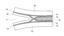
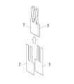
材に一体的に成形されて接合される態様も含みうる概念である。 According to the present invention, since the crack progress suppressing portion is provided so as to connect the first adhesive surface and the second adhesive surface directly or indirectly with another member interposed therebetween, for example, the first adhesive surface Even if there is a crack in the bonding portion between the second bonding surface and the second bonding surface, the crack growth suppressing portion can prevent the crack from progressing and increase the bonding strength. Thus, the progress of cracks can be suppressed when various loads are applied by a simple means of disposing the crack progress suppressing portion between the first member and the second member to be bonded. In addition, the crack progress suppression part may be provided so that it may join directly to a 1st adhesion surface and a 2nd adhesion surface, and may be provided so that it may join via an adhesive bond layer. In the present specification, “adhesion” is a concept that may include an aspect in which another member (fiber, resin) is interposed and an aspect in which the member is integrally formed and bonded to an adhesion target member.
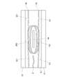
10a:第1部材
10b,20b:凹部
12:第1繊維部
14:第2繊維部
16:接着部
18:補強部
20:第2部材
20a:第2部材
101:第1領域
102:第2領域
103:第3領域
121:連続領域
122a,122b:短冊状領域
141:連続領域
142a,142b:短冊状領域
201:第1領域
202:第2領域
203:第3領域
10:
Claims (8)
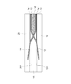
- 第1部材と第2部材とを対向状態で接着する接着構造であって、
前記第1部材と前記第2部材との間に配置される亀裂進展抑制部を備え、
前記第1部材は第1接着面を有し、前記第2部材は第2接着面を有するものであって、
前記亀裂進展抑制部は前記第1接着面及び前記第2接着面を繋ぐように設けられている、ことを特徴とする接着構造。 An adhesion structure for adhering the first member and the second member in an opposing state,
Comprising a crack growth suppressing portion disposed between the first member and the second member;
The first member has a first adhesive surface, and the second member has a second adhesive surface,
The adhesive structure according to claim 1, wherein the crack progress suppressing portion is provided so as to connect the first adhesive surface and the second adhesive surface. - 前記亀裂進展抑制部は、繊維を含み、前記繊維の配向方向が前記第1接着面から前記第2接着面に向かうように配置されている、ことを特徴とする請求項1に記載の接着構造。 2. The adhesive structure according to claim 1, wherein the crack propagation suppressing portion includes a fiber, and is arranged so that an orientation direction of the fiber is directed from the first adhesive surface to the second adhesive surface. .
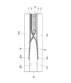
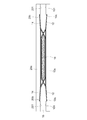
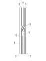
- 前記亀裂進展抑制部は、第1繊維部と、第2繊維部と、を有し、
前記第1接着面及び前記第2接着面はそれぞれ第1領域及び第2領域を有すると共に、前記第1領域と前記第2領域との間に設けられる第3領域を有しており、
前記第1繊維部は、前記第1接着面の前記第1領域と前記第2接着面の前記第2領域とを繋ぐように設けられ、
前記第2繊維部は、前記第1接着面の前記第2領域と前記第2接着面の前記第1領域とを繋ぐように設けられ、
前記第1部材と前記第2部材の間から前記第3領域を見通すと、前記第1繊維部と前記第2繊維部とが交差するように配置されている、ことを特徴とする請求項2に記載の接着構造。 The crack progress suppressing part has a first fiber part and a second fiber part,
The first adhesive surface and the second adhesive surface have a first region and a second region, respectively, and have a third region provided between the first region and the second region,
The first fiber portion is provided so as to connect the first region of the first adhesive surface and the second region of the second adhesive surface;
The second fiber portion is provided so as to connect the second region of the first adhesive surface and the first region of the second adhesive surface,
The first fiber portion and the second fiber portion are arranged so as to intersect each other when the third region is seen from between the first member and the second member. Adhesive structure described in 1. - 前記第1接着面の前記第1領域において前記第1繊維部が接着されている部分に凹部が形成され、前記第2接着面の前記第1領域において前記第2繊維部が接着されている部分に凹部が形成されている、ことを特徴とする請求項3に記載の接着構造。 A portion in which the first fiber portion is bonded to the first region of the first bonding surface and a recess is formed, and the second fiber portion is bonded to the first region of the second bonding surface. The adhesive structure according to claim 3, wherein a recess is formed in the adhesive structure.
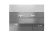
- 前記第1繊維部は、前記第1接着面の前記第1領域において前記第1部材に入り込んでおり、前記第2繊維部は、前記第2接着面の前記第1領域において前記第2部材に入り込んでいる、ことを特徴とする請求項3に記載の接着構造。 The first fiber portion enters the first member in the first region of the first adhesive surface, and the second fiber portion is in the second member in the first region of the second adhesive surface. The adhesive structure according to claim 3, wherein the adhesive structure is inserted.
- 前記第1部材と前記第2部材との間に配置される補強部及び接着部を備え、
前記第1繊維部及び前記第2繊維部は、それぞれ連続領域と短冊状領域とを有し、
前記第1繊維部の前記連続領域は前記第1接着面の前記第1領域と接着され、前記第2繊維部の前記連続領域は前記第2接着面の前記第1領域と接着され、前記第1繊維部の前記連続領域と前記第2繊維部の前記連続領域との間に前記接着部が配置され、
前記第1繊維部の前記短冊状領域と前記第2繊維部の前記短冊状領域とが直接接着され、繊維配向方向に沿って複数の短冊状領域が形成されるように切り込みが設けられており、前記複数の短冊状領域は前記第1接着面の前記第2領域と前記第2接着面の前記第2領域とに交互に接着され、その間に前記補強部が配置されている、ことを特徴とする請求項3に記載の接着構造。 A reinforcing portion and an adhesive portion disposed between the first member and the second member;
The first fiber portion and the second fiber portion each have a continuous region and a strip-like region,
The continuous region of the first fiber portion is bonded to the first region of the first bonding surface, the continuous region of the second fiber portion is bonded to the first region of the second bonding surface, and The adhesive portion is disposed between the continuous region of one fiber part and the continuous region of the second fiber part,
The strip-like region of the first fiber part and the strip-like region of the second fiber part are directly bonded, and notches are provided so that a plurality of strip-like regions are formed along the fiber orientation direction. The plurality of strip-shaped regions are alternately bonded to the second region of the first bonding surface and the second region of the second bonding surface, and the reinforcing portion is disposed therebetween. The adhesive structure according to claim 3. - 前記補強部は第3繊維部を有しており、
前記第1繊維部及び前記第2繊維部の繊維配向方向と、前記第3繊維部の繊維配向方向と、が交差している、ことを特徴とする請求項6に記載の接着構造。 The reinforcing part has a third fiber part,
The adhesive structure according to claim 6, wherein a fiber orientation direction of the first fiber part and the second fiber part intersects with a fiber orientation direction of the third fiber part. - 前記第1部材と前記第2部材との間に配置される補強部を備え、
前記第1繊維部は、前記第1接着面の前記第1領域及び前記第2領域に沿うように配置されると共に前記補強部を巻き込むように配置され、前記第2接着面の前記第2領域に沿うように配置され、
前記第2繊維部は、前記第2接着面の前記第1領域及び前記第2領域に沿うように配置されると共に前記補強部を巻き込むように配置され、前記第1接着面の前記第2領域に沿うように配置されている、ことを特徴とする請求項3に記載の接着構造。 A reinforcing portion disposed between the first member and the second member;
The first fiber portion is disposed along the first region and the second region of the first adhesive surface and is disposed so as to involve the reinforcing portion, and the second region of the second adhesive surface. Arranged along the
The second fiber portion is disposed along the first region and the second region of the second adhesive surface and is disposed so as to involve the reinforcing portion, and the second region of the first adhesive surface. The adhesive structure according to claim 3, wherein the adhesive structure is arranged along the line.
Priority Applications (3)
| Application Number | Priority Date | Filing Date | Title |
|---|---|---|---|
| JP2016574800A JP6681071B2 (en) | 2015-02-13 | 2016-02-09 | Adhesive structure |
| EP16749214.9A EP3258120A4 (en) | 2015-02-13 | 2016-02-09 | Bonded structure |
| US15/550,585 US10518484B2 (en) | 2015-02-13 | 2016-02-09 | Bonded structure |
Applications Claiming Priority (2)
| Application Number | Priority Date | Filing Date | Title |
|---|---|---|---|
| JP2015-026278 | 2015-02-13 | ||
| JP2015026278 | 2015-02-13 |
Publications (1)
| Publication Number | Publication Date |
|---|---|
| WO2016129570A1 true WO2016129570A1 (en) | 2016-08-18 |
Family
ID=56615339
Family Applications (1)
| Application Number | Title | Priority Date | Filing Date |
|---|---|---|---|
| PCT/JP2016/053723 WO2016129570A1 (en) | 2015-02-13 | 2016-02-09 | Bonded structure |
Country Status (4)
| Country | Link |
|---|---|
| US (1) | US10518484B2 (en) |
| EP (1) | EP3258120A4 (en) |
| JP (1) | JP6681071B2 (en) |
| WO (1) | WO2016129570A1 (en) |
Cited By (1)
| Publication number | Priority date | Publication date | Assignee | Title |
|---|---|---|---|---|
| JP2020180626A (en) * | 2019-04-23 | 2020-11-05 | 三菱重工業株式会社 | Adhesion member, adhesion member forming method and adhesion layer forming method |
Citations (5)
| Publication number | Priority date | Publication date | Assignee | Title |
|---|---|---|---|---|
| FR2219695A5 (en) * | 1973-02-26 | 1974-09-20 | Wakeman Alfred | |
| JPH06158739A (en) * | 1992-11-25 | 1994-06-07 | Matsushita Electric Works Ltd | Fitting construction for construction material |
| JP2006282046A (en) * | 2005-04-01 | 2006-10-19 | Kawasaki Heavy Ind Ltd | Separation development prevention structure of sandwich panel |
| JP4928403B2 (en) * | 2007-09-27 | 2012-05-09 | 社団法人日本航空宇宙工業会 | Structure for preventing delamination of sandwich panels |
| JP5219223B2 (en) * | 2009-10-27 | 2013-06-26 | 陽一郎 黒岩 | Wall panels |
Family Cites Families (5)
| Publication number | Priority date | Publication date | Assignee | Title |
|---|---|---|---|---|
| AU2459101A (en) * | 1999-12-28 | 2001-07-09 | Webcore Technologies, Inc. | Fiber reinforced composite cores and panels |
| DK1617993T3 (en) * | 2003-03-28 | 2014-05-26 | Milliken & Co | Core and fiber reinforced composite panels |
| JP2010032030A (en) | 2008-07-31 | 2010-02-12 | Toray Ind Inc | Bonded structure, and method of manufacturing the same |
| US8993084B2 (en) | 2010-08-17 | 2015-03-31 | The Boeing Company | Multi-layer metallic structure and composite-to-metal joint methods |
| US8652606B2 (en) | 2010-08-17 | 2014-02-18 | The Boeing Company | Composite structures having composite-to-metal joints and method for making the same |
-
2016
- 2016-02-09 WO PCT/JP2016/053723 patent/WO2016129570A1/en active Application Filing
- 2016-02-09 JP JP2016574800A patent/JP6681071B2/en active Active
- 2016-02-09 US US15/550,585 patent/US10518484B2/en not_active Expired - Fee Related
- 2016-02-09 EP EP16749214.9A patent/EP3258120A4/en not_active Withdrawn
Patent Citations (5)
| Publication number | Priority date | Publication date | Assignee | Title |
|---|---|---|---|---|
| FR2219695A5 (en) * | 1973-02-26 | 1974-09-20 | Wakeman Alfred | |
| JPH06158739A (en) * | 1992-11-25 | 1994-06-07 | Matsushita Electric Works Ltd | Fitting construction for construction material |
| JP2006282046A (en) * | 2005-04-01 | 2006-10-19 | Kawasaki Heavy Ind Ltd | Separation development prevention structure of sandwich panel |
| JP4928403B2 (en) * | 2007-09-27 | 2012-05-09 | 社団法人日本航空宇宙工業会 | Structure for preventing delamination of sandwich panels |
| JP5219223B2 (en) * | 2009-10-27 | 2013-06-26 | 陽一郎 黒岩 | Wall panels |
Non-Patent Citations (1)
| Title |
|---|
| See also references of EP3258120A4 * |
Cited By (2)
| Publication number | Priority date | Publication date | Assignee | Title |
|---|---|---|---|---|
| JP2020180626A (en) * | 2019-04-23 | 2020-11-05 | 三菱重工業株式会社 | Adhesion member, adhesion member forming method and adhesion layer forming method |
| JP7187378B2 (en) | 2019-04-23 | 2022-12-12 | 三菱重工業株式会社 | Adhesive member, method for forming adhesive member, and method for forming adhesive layer |
Also Published As
| Publication number | Publication date |
|---|---|
| US20180036962A1 (en) | 2018-02-08 |
| JPWO2016129570A1 (en) | 2017-11-24 |
| EP3258120A1 (en) | 2017-12-20 |
| US10518484B2 (en) | 2019-12-31 |
| EP3258120A4 (en) | 2018-10-24 |
| JP6681071B2 (en) | 2020-04-15 |
Similar Documents
| Publication | Publication Date | Title |
|---|---|---|
| JP5731192B2 (en) | COMPOSITE STRUCTURE COMPRISING STRINGER HAVING PAD EMBEDDED IN PANEL CONCRETE AND METHOD OF TRANSMITTING FORCE | |
| US6277463B1 (en) | Composite member having increased resistance to delamination and method of making same | |
| RU2479465C2 (en) | Laminar composite structure | |
| US20130209764A1 (en) | Composite laminate with self-healing layer | |
| JP6583966B2 (en) | Panel made of laminate and method for producing the same | |
| JP2008281429A (en) | Bonding strength evaluating method of double wrap coupling | |
| JP6204093B2 (en) | Method for manufacturing reinforcing structure | |
| WO2016129570A1 (en) | Bonded structure | |
| CA2923152A1 (en) | Joint, and aircraft structure | |
| EP2636509A2 (en) | Joint structure for fiber reinforced resin and metal, and joining method for fiber reinforced resin and metal | |
| WO2019044161A1 (en) | Composite material structure | |
| JP4928403B2 (en) | Structure for preventing delamination of sandwich panels | |
| JP2009046931A (en) | Repair method for steel material by carbon fiber reinforced plastic board and repaired steel material | |
| JP6317313B2 (en) | Bonding structure of metal member and FRP member | |
| JP3208178U (en) | Composite material | |
| JP6515654B2 (en) | Lap joint, method of manufacturing the same, and method of designing the same | |
| JP2007309470A (en) | Lap joint | |
| US11231060B2 (en) | Hybrid tension/transverse compression structural joint | |
| WO2015098147A1 (en) | Isogrid panel structure and method for manufacturing isogrid panel structure | |
| US20230135339A1 (en) | Sandwich panel and manufacturing method for sandwich panel | |
| JP2002307585A (en) | Frp structural material | |
| JP7390144B2 (en) | Composite joint members and joint structures | |
| JP2012171221A (en) | Bonded structure member | |
| KR100717719B1 (en) | Bonded joints of Composite adhesively | |
| Seo et al. | Effect of overlap length and adhesive thickness on stress distribution in adhesive bonded single-lap joints |
Legal Events
| Date | Code | Title | Description |
|---|---|---|---|
| 121 | Ep: the epo has been informed by wipo that ep was designated in this application |
Ref document number: 16749214 Country of ref document: EP Kind code of ref document: A1 |
|
| ENP | Entry into the national phase |
Ref document number: 2016574800 Country of ref document: JP Kind code of ref document: A |
|
| WWE | Wipo information: entry into national phase |
Ref document number: 15550585 Country of ref document: US |
|
| NENP | Non-entry into the national phase |
Ref country code: DE |
|
| REEP | Request for entry into the european phase |
Ref document number: 2016749214 Country of ref document: EP |