WO2016129364A1 - ガス発生器 - Google Patents
ガス発生器 Download PDFInfo
- Publication number
- WO2016129364A1 WO2016129364A1 PCT/JP2016/051953 JP2016051953W WO2016129364A1 WO 2016129364 A1 WO2016129364 A1 WO 2016129364A1 JP 2016051953 W JP2016051953 W JP 2016051953W WO 2016129364 A1 WO2016129364 A1 WO 2016129364A1
- Authority
- WO
- WIPO (PCT)
- Prior art keywords
- cylindrical
- holder
- outer peripheral
- peripheral wall
- closure shell
- Prior art date
- Legal status (The legal status is an assumption and is not a legal conclusion. Google has not performed a legal analysis and makes no representation as to the accuracy of the status listed.)
- Ceased
Links
Images


Classifications
-
- B—PERFORMING OPERATIONS; TRANSPORTING
- B01—PHYSICAL OR CHEMICAL PROCESSES OR APPARATUS IN GENERAL
- B01D—SEPARATION
- B01D46/00—Filters or filtering processes specially modified for separating dispersed particles from gases or vapours
- B01D46/24—Particle separators, e.g. dust precipitators, using rigid hollow filter bodies
- B01D46/2403—Particle separators, e.g. dust precipitators, using rigid hollow filter bodies characterised by the physical shape or structure of the filtering element
-
- B—PERFORMING OPERATIONS; TRANSPORTING
- B01—PHYSICAL OR CHEMICAL PROCESSES OR APPARATUS IN GENERAL
- B01D—SEPARATION
- B01D46/00—Filters or filtering processes specially modified for separating dispersed particles from gases or vapours
- B01D46/0002—Casings; Housings; Frame constructions
- B01D46/0005—Mounting of filtering elements within casings, housings or frames
-
- B—PERFORMING OPERATIONS; TRANSPORTING
- B01—PHYSICAL OR CHEMICAL PROCESSES OR APPARATUS IN GENERAL
- B01D—SEPARATION
- B01D46/00—Filters or filtering processes specially modified for separating dispersed particles from gases or vapours
- B01D46/0002—Casings; Housings; Frame constructions
- B01D46/001—Means for connecting filter housings to supports
-
- B—PERFORMING OPERATIONS; TRANSPORTING
- B01—PHYSICAL OR CHEMICAL PROCESSES OR APPARATUS IN GENERAL
- B01D—SEPARATION
- B01D46/00—Filters or filtering processes specially modified for separating dispersed particles from gases or vapours
- B01D46/24—Particle separators, e.g. dust precipitators, using rigid hollow filter bodies
-
- B—PERFORMING OPERATIONS; TRANSPORTING
- B01—PHYSICAL OR CHEMICAL PROCESSES OR APPARATUS IN GENERAL
- B01J—CHEMICAL OR PHYSICAL PROCESSES, e.g. CATALYSIS OR COLLOID CHEMISTRY; THEIR RELEVANT APPARATUS
- B01J7/00—Apparatus for generating gases
-
- B—PERFORMING OPERATIONS; TRANSPORTING
- B60—VEHICLES IN GENERAL
- B60R—VEHICLES, VEHICLE FITTINGS, OR VEHICLE PARTS, NOT OTHERWISE PROVIDED FOR
- B60R21/00—Arrangements or fittings on vehicles for protecting or preventing injuries to occupants or pedestrians in case of accidents or other traffic risks
- B60R21/02—Occupant safety arrangements or fittings, e.g. crash pads
- B60R21/16—Inflatable occupant restraints or confinements designed to inflate upon impact or impending impact, e.g. air bags
- B60R21/26—Inflatable occupant restraints or confinements designed to inflate upon impact or impending impact, e.g. air bags characterised by the inflation fluid source or means to control inflation fluid flow
-
- B—PERFORMING OPERATIONS; TRANSPORTING
- B60—VEHICLES IN GENERAL
- B60R—VEHICLES, VEHICLE FITTINGS, OR VEHICLE PARTS, NOT OTHERWISE PROVIDED FOR
- B60R21/00—Arrangements or fittings on vehicles for protecting or preventing injuries to occupants or pedestrians in case of accidents or other traffic risks
- B60R21/02—Occupant safety arrangements or fittings, e.g. crash pads
- B60R21/16—Inflatable occupant restraints or confinements designed to inflate upon impact or impending impact, e.g. air bags
- B60R21/26—Inflatable occupant restraints or confinements designed to inflate upon impact or impending impact, e.g. air bags characterised by the inflation fluid source or means to control inflation fluid flow
- B60R21/261—Inflatable occupant restraints or confinements designed to inflate upon impact or impending impact, e.g. air bags characterised by the inflation fluid source or means to control inflation fluid flow with means other than bag structure to diffuse or guide inflation fluid
-
- B—PERFORMING OPERATIONS; TRANSPORTING
- B60—VEHICLES IN GENERAL
- B60R—VEHICLES, VEHICLE FITTINGS, OR VEHICLE PARTS, NOT OTHERWISE PROVIDED FOR
- B60R21/00—Arrangements or fittings on vehicles for protecting or preventing injuries to occupants or pedestrians in case of accidents or other traffic risks
- B60R21/02—Occupant safety arrangements or fittings, e.g. crash pads
- B60R21/16—Inflatable occupant restraints or confinements designed to inflate upon impact or impending impact, e.g. air bags
- B60R21/26—Inflatable occupant restraints or confinements designed to inflate upon impact or impending impact, e.g. air bags characterised by the inflation fluid source or means to control inflation fluid flow
- B60R21/264—Inflatable occupant restraints or confinements designed to inflate upon impact or impending impact, e.g. air bags characterised by the inflation fluid source or means to control inflation fluid flow using instantaneous generation of gas, e.g. pyrotechnic
-
- B—PERFORMING OPERATIONS; TRANSPORTING
- B60—VEHICLES IN GENERAL
- B60R—VEHICLES, VEHICLE FITTINGS, OR VEHICLE PARTS, NOT OTHERWISE PROVIDED FOR
- B60R21/00—Arrangements or fittings on vehicles for protecting or preventing injuries to occupants or pedestrians in case of accidents or other traffic risks
- B60R21/02—Occupant safety arrangements or fittings, e.g. crash pads
- B60R21/16—Inflatable occupant restraints or confinements designed to inflate upon impact or impending impact, e.g. air bags
- B60R21/26—Inflatable occupant restraints or confinements designed to inflate upon impact or impending impact, e.g. air bags characterised by the inflation fluid source or means to control inflation fluid flow
- B60R21/264—Inflatable occupant restraints or confinements designed to inflate upon impact or impending impact, e.g. air bags characterised by the inflation fluid source or means to control inflation fluid flow using instantaneous generation of gas, e.g. pyrotechnic
- B60R21/2644—Inflatable occupant restraints or confinements designed to inflate upon impact or impending impact, e.g. air bags characterised by the inflation fluid source or means to control inflation fluid flow using instantaneous generation of gas, e.g. pyrotechnic using only solid reacting substances, e.g. pellets, powder
-
- B—PERFORMING OPERATIONS; TRANSPORTING
- B01—PHYSICAL OR CHEMICAL PROCESSES OR APPARATUS IN GENERAL
- B01D—SEPARATION
- B01D2279/00—Filters adapted for separating dispersed particles from gases or vapours specially modified for specific uses
- B01D2279/10—Filters adapted for separating dispersed particles from gases or vapours specially modified for specific uses for air bags, e.g. inflators therefor
-
- B—PERFORMING OPERATIONS; TRANSPORTING
- B60—VEHICLES IN GENERAL
- B60R—VEHICLES, VEHICLE FITTINGS, OR VEHICLE PARTS, NOT OTHERWISE PROVIDED FOR
- B60R21/00—Arrangements or fittings on vehicles for protecting or preventing injuries to occupants or pedestrians in case of accidents or other traffic risks
- B60R21/02—Occupant safety arrangements or fittings, e.g. crash pads
- B60R21/16—Inflatable occupant restraints or confinements designed to inflate upon impact or impending impact, e.g. air bags
- B60R21/26—Inflatable occupant restraints or confinements designed to inflate upon impact or impending impact, e.g. air bags characterised by the inflation fluid source or means to control inflation fluid flow
- B60R2021/26011—Inflatable occupant restraints or confinements designed to inflate upon impact or impending impact, e.g. air bags characterised by the inflation fluid source or means to control inflation fluid flow using a filter through which the inflation gas passes
-
- B—PERFORMING OPERATIONS; TRANSPORTING
- B60—VEHICLES IN GENERAL
- B60R—VEHICLES, VEHICLE FITTINGS, OR VEHICLE PARTS, NOT OTHERWISE PROVIDED FOR
- B60R21/00—Arrangements or fittings on vehicles for protecting or preventing injuries to occupants or pedestrians in case of accidents or other traffic risks
- B60R21/02—Occupant safety arrangements or fittings, e.g. crash pads
- B60R21/16—Inflatable occupant restraints or confinements designed to inflate upon impact or impending impact, e.g. air bags
- B60R21/26—Inflatable occupant restraints or confinements designed to inflate upon impact or impending impact, e.g. air bags characterised by the inflation fluid source or means to control inflation fluid flow
- B60R2021/26058—Inflatable occupant restraints or confinements designed to inflate upon impact or impending impact, e.g. air bags characterised by the inflation fluid source or means to control inflation fluid flow using a combination of inflators
-
- B—PERFORMING OPERATIONS; TRANSPORTING
- B60—VEHICLES IN GENERAL
- B60R—VEHICLES, VEHICLE FITTINGS, OR VEHICLE PARTS, NOT OTHERWISE PROVIDED FOR
- B60R21/00—Arrangements or fittings on vehicles for protecting or preventing injuries to occupants or pedestrians in case of accidents or other traffic risks
- B60R21/02—Occupant safety arrangements or fittings, e.g. crash pads
- B60R21/16—Inflatable occupant restraints or confinements designed to inflate upon impact or impending impact, e.g. air bags
- B60R21/26—Inflatable occupant restraints or confinements designed to inflate upon impact or impending impact, e.g. air bags characterised by the inflation fluid source or means to control inflation fluid flow
- B60R21/264—Inflatable occupant restraints or confinements designed to inflate upon impact or impending impact, e.g. air bags characterised by the inflation fluid source or means to control inflation fluid flow using instantaneous generation of gas, e.g. pyrotechnic
- B60R2021/2642—Inflatable occupant restraints or confinements designed to inflate upon impact or impending impact, e.g. air bags characterised by the inflation fluid source or means to control inflation fluid flow using instantaneous generation of gas, e.g. pyrotechnic comprising a plurality of combustion chambers or sub-chambers
-
- B—PERFORMING OPERATIONS; TRANSPORTING
- B60—VEHICLES IN GENERAL
- B60R—VEHICLES, VEHICLE FITTINGS, OR VEHICLE PARTS, NOT OTHERWISE PROVIDED FOR
- B60R21/00—Arrangements or fittings on vehicles for protecting or preventing injuries to occupants or pedestrians in case of accidents or other traffic risks
- B60R21/02—Occupant safety arrangements or fittings, e.g. crash pads
- B60R21/16—Inflatable occupant restraints or confinements designed to inflate upon impact or impending impact, e.g. air bags
- B60R21/26—Inflatable occupant restraints or confinements designed to inflate upon impact or impending impact, e.g. air bags characterised by the inflation fluid source or means to control inflation fluid flow
- B60R21/264—Inflatable occupant restraints or confinements designed to inflate upon impact or impending impact, e.g. air bags characterised by the inflation fluid source or means to control inflation fluid flow using instantaneous generation of gas, e.g. pyrotechnic
- B60R21/2644—Inflatable occupant restraints or confinements designed to inflate upon impact or impending impact, e.g. air bags characterised by the inflation fluid source or means to control inflation fluid flow using instantaneous generation of gas, e.g. pyrotechnic using only solid reacting substances, e.g. pellets, powder
- B60R2021/2648—Inflatable occupant restraints or confinements designed to inflate upon impact or impending impact, e.g. air bags characterised by the inflation fluid source or means to control inflation fluid flow using instantaneous generation of gas, e.g. pyrotechnic using only solid reacting substances, e.g. pellets, powder comprising a plurality of combustion chambers or sub-chambers
Definitions
- This invention relates to the gas generator which can be used with the airbag apparatus mounted in a motor vehicle.
- a gas generator using a gas generating agent as a gas generating source is widely used.
- the combustion gas may contain mist containing a molten metal. Mist contained in the combustion gas is filtered by a coolant filter disposed in the housing of the gas generator, and is difficult to be released from the gas generator into the airbag.
- a coolant / filter support member 432 is press-fitted on the top plate side of the housing (paragraph number 0134).
- the coolant support member 32 is press-fitted on the top plate side of the housing (paragraph number 0041).
- the coolant means support member 50 is press-fitted and arranged on the top plate side of the housing (paragraph number 0037).
- a cylindrical filter is arranged in a housing composed of a diffuser shell having a gas discharge port and a closure shell, and a first combustion chamber and a second combustion chamber are arranged inside the cylindrical filter.
- a gas generator The cylindrical filter has an outer peripheral surface spaced from the gas discharge port, a first annular end surface abutting against the top plate of the diffuser shell, and a second annular end surface abutting against the bottom plate of the closure shell.
- the first combustion chamber includes an ignition means chamber having an ignition means for the first b gas generating agent filled in the first combustion chamber, and an outer space of the second combustion chamber filled with the second gas generating agent.
- the ignition means chamber is surrounded by a first cup member having a cylindrical first holder, a first igniter, and a plurality of first communication holes penetrating in the thickness direction in the peripheral wall portion, It consists of a space filled with the first gas generating agent,
- the cylindrical first holder is fixed in a first hole of a bottom plate of the closure shell, the first igniter is fixed in the cylindrical first holder, and the first cup member is opened. It is press-fitted into the inside of the cylindrical first holder from the part side,
- the second combustion chamber is surrounded by a second cup member having a cylindrical second holder, a second igniter, and a plurality of second communication holes penetrating in the thickness direction in the peripheral wall portion.
- a space filled with a second gas generating agent The cylindrical second holder is fixed to a second hole of a bottom plate of the closure shell, the second igniter is fixed in the cylindrical second holder, and the second cup member is opened.
- the surface including the plurality of second communication holes of the peripheral wall portion is press-fitted into the outer side of the cylindrical second holder from the part side, and is covered with a cover member from the outer side,
- the support member of the cylindrical filter is disposed on the bottom surface of the closure shell,
- the support member includes a bottom surface portion having holes corresponding to a first hole portion and a second hole portion formed in a bottom plate portion of the closure shell, and an outer peripheral wall portion extending vertically from the outer peripheral portion of the bottom surface portion.
- the second annular end surface of the filter is in contact with the contact portion of the bottom plate of the closure shell,
- the second igniter is activated and the second gas generating agent in the second combustion chamber is ignited and combusted to increase the internal pressure, it burns in the direction toward the bottom plate of the closure shell from between the second communication hole and the cover member.
- a gas generator is provided wherein gas is effluxed.
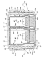
- FIG. 1 is an axial sectional view of a gas generator of the present invention.
- FIG. 2 is a partial view of FIG.
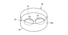
- FIG. 3 is a perspective view of a cylindrical filter support member used in the gas generator of FIG.
- FIG. 4 is a perspective view of a cylindrical filter support member according to an embodiment different from that shown in FIG. 3.
- the present invention fixes a cylindrical filter support member by a combination of a housing and another member, and from the contact portion between the housing bottom plate and the cylindrical filter by the cylindrical filter support member. It is an object of the present invention to provide a gas generator that can prevent a short pass.
- combustion gas flows in the direction of the bottom plate of the housing during operation, and the combustion gas is short-passed between the cylindrical filter and the housing bottom plate by the support member of the cylindrical filter. It is to prevent.
- the support member includes a bottom surface portion having a hole corresponding to the first hole portion and the second hole portion formed in the bottom plate portion of the closure shell, and an outer peripheral wall portion suspended from the outer peripheral portion of the bottom surface portion. Yes. Since the outer peripheral wall portion of the support member is in contact with the inner peripheral surface on the second annular end surface side of the cylindrical filter, the corner portion formed by the bottom surface portion and the outer peripheral wall portion of the support member is the second portion of the cylindrical filter.
- the cylindrical filter is a JP-A no. H10-95304, JP-A No. 2001-206189, JP-A No. 2001-233167, JP-A no.
- the same coolant filter or coolant described in H11-334517 can be used.
- the support member is press-fitted into the inner peripheral surface of the cylindrical filter, and a part of the outer peripheral wall portion is sandwiched between the first holder and the cylindrical filter from the thickness direction, and the second cup member and the housing bottom plate The bottom portion is fixed by being sandwiched from the thickness direction.
- the support member is not simply press-fitted and fixed, but is sandwiched and fixed in the thickness direction in combination with other members, and thus includes the bottom surface portion and the outer peripheral wall portion of the support member. The contact state between the corner portion, the second annular end surface of the cylindrical filter, and the contact portion between the bottom plate of the closure shell is maintained.
- annular end surface of a cylindrical filter and the bottom plate of a closure shell is heightened by the corner
- the ratio (h2 / h1) of the height (h1) on the inner peripheral surface side of the cylindrical filter to the height (h2) of the outer peripheral wall portion of the support member is 0.1 to 0. Those in the range of .2 are preferred. By setting it in the above range, the short path prevention function is enhanced and the passage of the combustion gas flow to the cylindrical filter is not hindered.
- the diffuser shell has an inner flat surface and an upper annular inclined surface inclined downward on the outer peripheral side
- the closure shell has an inner flat surface and a lower annular inclined surface inclined upward on the outer peripheral side
- the first annular end surface of the cylindrical filter has an inclined surface that can contact the upper annular inclined surface
- the second annular end surface of the cylindrical filter has an inclined surface that can contact the lower annular inclined surface.
- the first annular end surface of the cylindrical filter is in contact with the upper annular inclined surface of the diffuser shell, and the second annular end surface of the cylindrical filter is in contact with the lower annular inclined surface of the closure shell. .
- the short path of the combustion gas from the contact surface between the closure shell and the cylindrical filter is prevented by the support member of the cylindrical filter disposed in the housing.
- the gas generator of the present invention can be used for an airbag device mounted on an automobile.
- a gas generator 1 shown in FIG. 1 has a housing 10 including a diffuser shell 11 and a closure shell 20.
- the diffuser shell 11 and the closure shell 20 are made of metal such as iron or stainless steel.
- the diffuser shell 11 has a top plate 12 and an upper peripheral wall portion 13, and has a flange portion 14 on the opening side.
- a plurality of gas discharge ports 15 are formed in the upper peripheral wall portion 13 at equal intervals in the circumferential direction, and the gas discharge ports 15 are closed with a seal tape 16 from the inside.
- the closure shell 20 has a bottom plate 21 and a lower peripheral wall portion 22, and a first hole portion 23 and a second hole portion 24 for attaching two igniters are formed in the bottom plate 21.
- the housing 10 is welded and integrated at the contact portion 25 between the inner side surface of the upper peripheral wall portion 13 and the outer side surface of the lower peripheral wall portion 22 in a state where the closure shell 20 is covered with the diffuser shell 11.
- a cylindrical filter 30 is disposed in the housing 10.
- the cylindrical filter 30 is disposed such that the outer peripheral surface 31 a is spaced from both the upper peripheral wall portion 13 and the lower peripheral wall portion 22 having the gas discharge ports 15.
- the first annular end surface 32 of the cylindrical filter 30 is in contact with the top plate 12 of the diffuser shell 11, and the opposite second annular end surface 33 is in contact with the bottom plate 21 of the closure shell 20.
- the top plate 12 has an upper inclined surface 12 a inclined downward on the outer peripheral side of the top plate 12, the remaining portion is a flat surface, and the bottom plate 21 is inclined upward on the outer peripheral side.
- the lower inclined surface 21a is provided, and the remaining portion is a flat surface.
- the first annular end surface 32 of the tubular filter 30 has an inclined surface corresponding to the upper inclined surface 12a, and the second annular end surface 33 has an inclined surface corresponding to the lower inclined surface 21a.
- the surfaces are positioned by contacting each other.
- the top plate 12 and the bottom plate 21 may be flat surfaces having no inclined surface, and the first annular end surface 32 and the second annular end surface 33 of the cylindrical filter 30 may also be flat surfaces.
- a first combustion chamber 40 and a second combustion chamber 50 are arranged inside the cylindrical filter 30.
- the first combustion chamber 40 comprises an outer space excluding the ignition means chamber 42 and the second combustion chamber 50.
- the first combustion chamber 40 is filled with a required amount of the first b gas generating agent 41b.
- the ignition means chamber 42 includes a space surrounded by a cylindrical first holder 43, a first igniter 44, and a first cup member 45.
- the first holder 43 can be made of the same material as the closure shell 20, and the first cup member 45 is preferably made of iron, stainless steel, aluminum or the like.
- the ignition means chamber 42 is filled with a required amount of the 1a gas generating agent 41a.
- a cushioning material can be disposed on the bottom surface 47 side of the first cup member 45 as necessary.
- the cylindrical first holder 43 is fitted into the first hole 23 of the bottom plate 21 of the closure shell, and is welded and fixed at the contact portion.
- the first igniter 44 is fixed in the cylindrical first holder 43. In the embodiment of FIG. 1, as shown in FIG.
- the metal collar 44 a of the first igniter 44 is inserted into an annular step surface 43 a formed on the inner peripheral wall surface of the cylindrical first holder 43. ing.
- the first cup member 45 is press-fitted inside the cylindrical first holder 43 from the opening 45a side, and a metal collar 44a is sandwiched between the annular end surface 46a and the annular step surface 43a of the opening 45a.
- An O-ring 49 is fitted in an annular gap between the metal collar 44 a and the inner peripheral wall surface of the first holder 43 in order to provide moisture resistance.
- the first cup member 45 has an outer diameter on the opening 45 a side larger than an outer diameter on the bottom surface 47 side, and has a stepped portion 48 between the opening 45 a and the bottom surface portion 47.
- the first cup member 45 has a plurality of first communication holes 46 b in the circumferential direction in the peripheral wall portion 46 between the stepped portion 48 and the bottom surface portion 47.
- the plurality of first communication holes 46b can be closed with a seal tape from the inside.
- the plurality of second communication holes 65 formed in the plurality of first communication holes 46 b and the peripheral wall portion 64 of the second cup member 60 have different heights in the axis X direction.
- the caulking portion 43b on the top plate 12 side of the cylindrical first holder 43 presses the stepped portion 48 of the first cup member 45 inward in the radial direction. Dropping out is prevented.
- the second combustion chamber 50 has a cylindrical second holder 52, a second igniter 53, and a second cup member having a plurality of second communication holes 65 penetrating the peripheral wall portion 64 in the thickness direction. It consists of a space surrounded by 60.
- the second holder 52 can be made of the same material as the closure shell 20, and the second cup member 60 is preferably made of iron, stainless steel, aluminum or the like.
- the second combustion chamber 50 is filled with a required amount of the second gas generating agent 51.
- a cushion material can be disposed on the bottom surface 62 side of the second cup member 60 as necessary.
- the cylindrical second holder 52 is fitted into the second hole 24 of the bottom plate 21 of the closure shell, and is welded and fixed at the contact portion.
- the second igniter 53 is fixed in the cylindrical second holder 52.
- the metal collar 53 a of the second igniter 53 is inserted into an annular step surface 52 a formed on the inner peripheral wall surface of the cylindrical second holder 52. Further, the metal collar 53a is pressed and fixed by the caulking portion 52b of the cylindrical second holder 52.
- An O-ring 59 is fitted in an annular gap between the metal collar 53a and the inner peripheral wall surface of the second holder 52 in order to provide moisture resistance.
- the second cup member 60 is press-fitted outside the cylindrical second holder 52 from the opening 61 side.
- the second cup member 60 has an outer diameter on the opening 61 side smaller than an outer diameter on the bottom surface 62 side, and has a stepped portion 63 between the opening 61 and the bottom surface 62.
- the second cup member 60 has a plurality of second communication holes 65 in the circumferential direction in the peripheral wall portion 64 between the step portion 63 and the bottom surface portion 62.
- the surface including the some 2nd communicating hole 65 of the bottom face part 62 and the surrounding wall part 64 is covered with the cup-shaped cover member 67 from the outer side.
- the cover member 67 only needs to be able to cover at least the surface including the plurality of second communication holes 65 of the peripheral wall portion 64, and may be cylindrical.
- the cover member 67 is made of metal, and preferably made of cold rolled steel plate (SPCC).
- the cover member 67 When the cover member 67 receives a pressure of the combustion gas ejected from the second communication hole 65 of the second cup member 60 by forming a notch (for example, a portion cut into a triangle) on the opening side, It is possible to make the combustion gas easily flow out to the bottom plate 21 side by cleaving from the notch.
- a notch for example, a portion cut into a triangle
- a support member 70 for the cylindrical filter 30 is disposed on the bottom plate 21 of the closure shell 20.
- the support member 70 includes a bottom surface portion 71 and an outer peripheral wall portion 74 that is suspended from the outer peripheral portion of the bottom surface portion 71.
- the bottom surface 71 has a hole 72 having the same shape and size as the first hole 23 formed in the bottom plate 21 of the closure shell 20 and a hole 73 having the same shape and size as the second hole 24. .
- the outer peripheral surface 74 a of the outer peripheral wall portion 74 is in contact with the inner peripheral surface 31 b on the second annular end surface 33 side of the cylindrical filter 30, and a part of the outer peripheral wall portion 74 is part of the first holder 43.
- the inner peripheral surface 31b of the cylindrical filter 30 are sandwiched from both sides in the thickness direction.
- the bottom surface 71 of the support member 70 is sandwiched between the bottom plate 21 of the closure shell 20 and the annular end surface 61a of the opening 61 of the second cup member 60 from both sides in the thickness direction.
- a corner portion 75 including a bottom surface portion 71 and an outer peripheral wall portion 74 abuts on a contact portion between the second annular end surface 33 of the tubular filter 30 and the lower inclined surface 21 a of the bottom plate 21 of the closure shell 20.
- the ratio of the height on the inner peripheral surface side of the cylindrical filter 30, that is, the height (h 1) from the housing bottom plate 21 to the top plate 12 and the height (h 2) of the outer peripheral wall portion 74 of the support member 70 ( h2 / h1) is preferably in the range of 0.1 to 0.2, more preferably in the range of 0.1 to 0.15.
- h2 / h1 is within the above range, the function of preventing a short path from the contact portion between the second annular end surface 33 and the lower inclined surface 21a is sufficiently enhanced, and the combustion gas is filtered through the cylindrical filter 30. And, after being cooled, the function of being discharged from the gas discharge port 15 is also maintained.
- the support member 71 may have a bottom portion 71 having one hole 80.
- One hole 80 has a shape and size including a first hole 23 and a second hole 24 formed in the bottom plate 21 of the closure shell 20.
- the inner peripheral portion 81 of the hole 80 can come into contact with a part of the outer peripheral surface of the first holder 43 and a part of the outer peripheral surface of the second holder 52.
- the gas generator 1 can arrange
- the combustion gas flows into the first combustion chamber 40 from the first communication hole 46b of the first cup member 45. Then, the 1b gas generating agent 41b is ignited and burned.
- the pressure in the first combustion chamber 40 is further increased by the combustion of the first b gas generating agent 41b, the top plate 12 is deformed in the axis X direction. At this time, the upper inclined surface 12a of the outer peripheral portion of the top plate 12 is deformed. It is difficult to deform the remaining flat surface.
- the second communication hole 65 of the second cup member 60 is used. Is covered with a metal cover member 67, the second gas generating agent 51 in the second combustion chamber 50 is not ignited by the combustion gas.
- the combustion gas in the first combustion chamber 40 passes through the cylindrical filter 30, breaks the seal tape 16, and is discharged from the gas discharge port 15 into the airbag. Thereafter, the second igniter 53 is activated, and the second gas generating agent 51 in the second combustion chamber 50 is ignited and combusted to generate combustion gas. Since the second communication hole 65 of the second combustion chamber 50 is covered with the cover member 67, the combustion gas flows toward the bottom plate 21 from the gap between the second communication hole 65 and the cover member 67.
- a corner portion 75 including a bottom surface portion 71 and an outer peripheral wall portion 74 abuts on a contact portion between the second annular end surface 33 of the tubular filter 30 and the lower inclined surface 21 a of the bottom plate 21 of the closure shell 20.
- the corner portion composed of the bottom surface portion 71 and the outer peripheral wall portion 74 is formed. 75 prevents a short path of combustion gas.
Landscapes
- Chemical & Material Sciences (AREA)
- Physics & Mathematics (AREA)
- Chemical Kinetics & Catalysis (AREA)
- Fluid Mechanics (AREA)
- Engineering & Computer Science (AREA)
- Mechanical Engineering (AREA)
- Organic Chemistry (AREA)
- Geometry (AREA)
- Air Bags (AREA)
Abstract
Description
自動車に搭載するエアバッグ装置に使用するガス発生器としては、ガス発生源としてガス発生剤を使用したものが汎用されている。
ガス発生器の点火器が作動してガス発生剤が燃焼したとき、燃焼ガス中に溶融状態の金属を含むミストが含まれる場合がある。
燃焼ガスに含まれるミストは、ガス発生器のハウジング内に配置されたクーラントフィルタにより濾過され、ガス発生器からエアバッグ内に放出され難くなっている。
このようなショートパスの発生を防止するため、JP-A No.H10-95304の図16では、ハウジングの天板側にクーラント/フィルタ支持部材432が圧入して配置され(段落番号0134)、JP-A No.2001-206189の図2では、ハウジングの天板側にクーラント支持部材32が圧入して配置され(段落番号0041)、JP-A No.2001-233167の図2では、ハウジングの天板側にクーラント手段支持部材50が圧入して配置されている(段落番号0037)。
JP-A No.H11-334517の図12では、ショートパスを防止する目的でハウジングの天板側にクーラント支持部材55が配置され(段落番号0050)、ハウジングの底板側に仕切部材110が配置されている。
本発明は、ガス排出口を有するディフューザシェルとクロージャシェルからなるハウジング内に筒状フィルタが配置され、前記筒状フィルタの内側に第1燃焼室と第2燃焼室が配置されたガス発生器であって、
前記筒状フィルタが、外周面が前記ガス排出口と間隔をおいて、第1環状端面が前記ディフューザシェルの天板に当接され、第2環状端面が前記クロージャシェルの底板に当接されて配置されており、
前記第1燃焼室が、前記第1燃焼室内に充填された第1bガス発生剤の点火手段を有する点火手段室と、第2ガス発生剤が充填された前記第2燃焼室の外側空間からなるものであり、
前記点火手段室が、筒状の第1ホルダと、第1点火器と、周壁部に厚さ方向に貫通された複数の第1連通孔を有している第1カップ部材で囲まれた、第1aガス発生剤が充填された空間からなり、
前記筒状の第1ホルダが、前記クロージャシェルの底板の第1穴部に固定され、前記第1点火器が、前記筒状の第1ホルダ内に固定され、前記第1カップ部材が、開口部側から前記筒状の第1ホルダの内側に圧入されているものであり、
前記第2燃焼室が、筒状の第2ホルダと、第2点火器と、周壁部に厚さ方向に貫通された複数の第2連通孔を有している第2カップ部材で囲まれた第2ガス発生剤が充填された空間からなり、
前記筒状の第2ホルダが、前記クロージャシェルの底板の第2穴部に固定され、前記第2点火器が、前記筒状の第2ホルダ内に固定され、前記第2カップ部材が、開口部側から前記筒状の第2ホルダの外側に圧入され、前記周壁部の複数の第2連通孔を含む面が外側からカバー部材で覆われているものであり、
さらにクロージャシェルの底面には前記筒状フィルタの支持部材が配置されており、
前記支持部材が、前記クロージャシェルの底板部に形成された第1穴部と第2穴部に対応する穴を有する底面部と、前記底面部の外周部から垂設された外周壁部を有しているものであり、
前記支持部材の外周壁部の一部が、前記第1ホルダと前記筒状フィルタの間で厚さ方向両側から挟み付けられており、
前記支持部材の底面部が、前記クロージャシェルの底板と前記筒状の第2ホルダに圧入された前記第2カップ部材の開口部の環状端面の間で厚さ方向両側から挟み付けられており、
前記支持部材の外周壁部が前記筒状フィルタの第2環状端面側の内周面に当接されていることで、前記支持部材の底面部と外周壁部からなる角部が、前記筒状フィルタの第2環状端面と前記クロージャシェルの底板との当接部に当接されているものであり、
第2点火器が作動して、第2燃焼室内の第2ガス発生剤が着火燃焼されて内部の圧力が上昇したとき、第2連通孔とカバー部材の間から前記クロージャシェルの底板方向に燃焼ガスが流出されるものである、ガス発生器を提供する。
本発明は、ハウジングと他部材との組み合わせで筒状フィルタの支持部材を固定すると共に、前記筒状フィルタの支持部材によって、ハウジング底板と筒状フィルタとの当接部分からのショートパスを防止することができる、ガス発生器を提供することを課題とする。
支持部材は、クロージャシェルの底板部に形成された第1穴部と第2穴部に対応する穴を有する底面部と、前記底面部の外周部から垂設された外周壁部を有している。
支持部材の外周壁部は、筒状フィルタの第2環状端面側の内周面に当接されているため、支持部材の底面部と外周壁部からなる角部は、筒状フィルタの第2環状端面とクロージャシェルの底板との当接部に当接されている。
ガス発生器の作動時において、筒状フィルタの第2環状端面とクロージャシェルの底板との当接部に隙間が生じたとき、前記隙間から燃焼ガスのショートパスが生じるおそれがあるが、本発明のガス発生器では、前記隙間に当接された支持部材の底面部と外周壁部からなる角部がショートパスを防止するように作用する。
筒状フィルタは、JP-A No.H10-95304、JP-A No.2001-206189、JP-A No.2001-233167、JP-A No.H11-334517に記載されているクーラントフィルタまたはクーラントと同じものを使用することができる。
このように支持部材は、単に圧入して固定されているものではなく、他部材との組み合わせで厚さ方向から挟み付けられて固定されているため、支持部材の底面部と外周壁部からなる角部と筒状フィルタの第2環状端面とクロージャシェルの底板との当接部との接触状態が維持される。
このため、支持部材の底面部と外周壁部からなる角部によって、筒状フィルタの第2環状端面とクロージャシェルの底板との当接部からのショートパス防止機能が高められている。
前記範囲にすることで、ショートパス防止機能が高められ、筒状フィルタへの燃焼ガス流の通過も妨げられない。
前記クロージャシェルが、内側の平坦面と、外周側の上向きに傾斜した下部環状傾斜面を有しており、
前記筒状フィルタの第1環状端面が前記上部環状傾斜面に当接できる傾斜面を有し、前記筒状フィルタの第2環状端面が前記下部環状傾斜面に当接できる傾斜面を有しており、
前記ディフューザシェルの上部環状傾斜面に前記筒状フィルタの第1環状端面が当接され、前記クロージャシェルの下部環状傾斜面に前記筒状フィルタの第2環状端面が当接されているものが好ましい。
このようにすることで、筒状フィルタの位置決めが容易になる。
図1に示すガス発生器1は、ディフューザシェル11とクロージャシェル20からなるハウジング10を有している。ディフューザシェル11とクロージャシェル20は、鉄、ステンレスなどの金属からなるものである。
ディフューザシェル11は、天板12、上部周壁部13を有しており、開口部側にフランジ部14を有している。
上部周壁部13には、周方向に均等間隔で複数のガス排出口15が形成されており、ガス排出口15は内側からシールテープ16で閉塞されている。
クロージャシェル20は、底板21、下部周壁部22を有しており、底板21には、2つの点火器を取り付けるための第1穴部23、第2穴部24が形成されている。
ハウジング10は、クロージャシェル20にディフューザシェル11が被せられた状態で、上部周壁部13の内側面と下部周壁部22の外側面の接触部25において溶接一体化されている。
筒状フィルタ30は、外周面31aがガス排出口15を有する上部周壁部13と下部周壁部22の両方と間隔をおいて配置されている。
筒状フィルタ30の第1環状端面32はディフューザシェル11の天板12に当接され、反対側の第2環状端面33はクロージャシェル20の底板21に当接されている。
筒状フィルタ30の第1環状端面32は上部傾斜面12aに対応した傾斜面を有しており、第2環状端面33は下部傾斜面21aに対応した傾斜面を有しており、それぞれの傾斜面同士が当接されることで位置決めされている。
なお、天板12と底板21が傾斜面のない平坦面からなるものであり、筒状フィルタ30の第1環状端面32と第2環状端面33も平坦面であるものを使用することもできる。
第1燃焼室40は、点火手段室42と第2燃焼室50を除いた外側空間からなるものである。
第1燃焼室40内には、所要量の第1bガス発生剤41bが充填されている。
第1ホルダ43は、クロージャシェル20と同じ材質からなるものを用いることができ、第1カップ部材45は、鉄、ステンレス、アルミニウムなどからなるものが好ましい。
点火手段室42内には、所要量の第1aガス発生剤41aが充填されている。第1カップ部材45の底面部47側には、必要に応じてクッション材を配置することができる。
筒状の第1ホルダ43は、クロージャシェルの底板21の第1穴部23に嵌め込まれ、接触部において溶接固定されている。
第1点火器44は、筒状の第1ホルダ43内に固定されている。
図1の実施形態では、図2に示すように、筒状の第1ホルダ43の内周壁面に形成された環状段差面43aに第1点火器44の金属カラー44aが位置するように挿入されている。
第1カップ部材45は、開口部45a側から筒状の第1ホルダ43の内側に圧入されており、開口部45aの環状端面46aと環状段差面43aの間で金属カラー44aが挟み付けられている。
金属カラー44aと第1ホルダ43の内周壁面との環状の隙間には、防湿性を付与するため、Oリング49が嵌め込まれている。
第1カップ部材45は、段差部48から底面部47の間の周壁部46において、周方向に複数の第1連通孔46bを有している。複数の第1連通孔46bは、内側からシールテープで閉塞することもできる。
複数の第1連通孔46bと第2カップ部材60の周壁部64に形成された複数の第2連通孔65は、軸X方向の高さが異なっている。
筒状の第1ホルダ43の天板12側のかしめ部43bが、第1カップ部材45の段差部48を半径方向内側に押し付けているため、作動前には第1カップ部材45の軸X方向への脱落が防止されている。
第2ホルダ52は、クロージャシェル20と同じ材質からなるものを用いることができ、第2カップ部材60は、鉄、ステンレス、アルミニウムなどからなるものが好ましい。
第2燃焼室50内には、所要量の第2ガス発生剤51が充填されている。第2カップ部材60の底面部62側には、必要に応じてクッション材を配置することができる。
第2点火器53は、筒状の第2ホルダ52内に固定されている。
図1の実施形態では、図2に示すように、筒状の第2ホルダ52の内周壁面に形成された環状段差面52aに第2点火器53の金属カラー53aが位置するように挿入され、さらに筒状の第2ホルダ52のかしめ部52bにより金属カラー53aが押さえつけられることで固定されている。
金属カラー53aと第2ホルダ52の内周壁面との環状の隙間には、防湿性を付与するため、Oリング59が嵌め込まれている。
第2カップ部材60は、開口部61側の外径が底面部62側の外径よりも小さく、開口部61から底面部62の間に段差部63を有している。
第2カップ部材60は、段差部63から底面部62の間の周壁部64において、周方向に複数の第2連通孔65を有している。
カバー部材67は、少なくとも周壁部64の複数の第2連通孔65を含む面を覆うことができるものであればよく、筒形状のものでもよい。
カバー部材67は、金属からなるものであり、好ましくは冷間圧延鋼板(SPCC)からなるものを使用することができる。
カバー部材67は、開口部側に切り欠き(例えば、三角に切り取られた部分)を形成して、第2カップ部材60の第2連通孔65から噴き出した燃焼ガスの圧力を受けたとき、前記切り欠き部分から開裂して、燃焼ガスが底板21側に流出し易くなるようにすることができる。
支持部材70は、図3に示すとおり、底面部71と、底面部71の外周部から垂設された外周壁部74を有している。
底面部71は、クロージャシェル20の底板21に形成された第1穴部23と同じ形状および大きさの穴72と、第2穴部24と同じ形状および大きさの穴73を有している。
支持部材70の穴72と穴73は、図1に示すように配置したとき、穴72と第1穴部23が一致し、穴73と第2穴部24と一致するように位置が調整されている。
支持部材70の底面部71は、クロージャシェル20の底板21と第2カップ部材60の開口部61の環状端面61aの間で、厚さ方向両側から挟み付けられている。
支持部材70は、底面部71と外周壁部74からなる角部75が、筒状フィルタ30の第2環状端面33とクロージャシェル20の底板21の下部傾斜面21aとの当接部に当接されている。
h2/h1が前記範囲内であると、第2環状端面33と下部傾斜面21aの当接部分からのショートパス防止機能が十分に高められると共に、燃焼ガスが筒状フィルタ30を通過して濾過および冷却された後、ガス排出口15から排出される機能も維持される。
一つの穴80は、クロージャシェル20の底板21に形成された第1穴部23と第2穴部24を含む形状および大きさのものである。
穴80の内周部81は、第1ホルダ43の外周面の一部と第2ホルダ52の外周面の一部に当接できるようになっている。
ガス発生器1は、必要に応じて、ガス発生剤41bを支持するためのリテーナを配置することができる。
以下においては、最初に第1点火器44が作動して、僅かに遅れて第2点火器53が作動したときの動作について説明する。
第1bガス発生剤41bの燃焼により第1燃焼室40内の圧力がさらに上昇すると、天板12は軸X方向に変形するが、このとき天板12の外周部分の上部傾斜面12aは変形し難く、残部の平坦面が変形し易くなる。
なお、点火手段室42内の第1aガス発生剤41aと第1燃焼室40内の第1bガス発生剤が燃焼して燃焼ガスが発生したときでも、第2カップ部材60の第2連通孔65は金属製のカバー部材67で覆われているため、前記燃焼ガスにより第2燃焼室50内の第2ガス発生剤51が着火されることはない。
その後、第2点火器53が作動して、第2燃焼室50内の第2ガス発生剤51が着火燃焼して燃焼ガスが発生する。
第2燃焼室50の第2連通孔65はカバー部材67で覆われているため、燃焼ガスは第2連通孔65とカバー部材67の隙間から、底板21方向に流れる。
このため、筒状フィルタ30の第2環状端面33とクロージャシェル20の底板21の下部傾斜面21aの間に隙間が生じた場合であっても、底面部71と外周壁部74からなる角部75により燃焼ガスのショートパスが防止される。
Claims (3)
- ガス排出口を有するディフューザシェルとクロージャシェルからなるハウジング内に筒状フィルタが配置され、前記筒状フィルタの内側に第1燃焼室と第2燃焼室が配置されたガス発生器であって、
前記筒状フィルタが、外周面が前記ガス排出口と間隔をおいて、第1環状端面が前記ディフューザシェルの天板に当接され、第2環状端面が前記クロージャシェルの底板に当接されて配置されており、
前記第1燃焼室が、前記第1燃焼室内に充填された第1bガス発生剤の点火手段を有する点火手段室と、第2ガス発生剤が充填された前記第2燃焼室の外側空間からなるものであり、
前記点火手段室が、筒状の第1ホルダと、第1点火器と、周壁部に厚さ方向に貫通された複数の第1連通孔を有している第1カップ部材で囲まれた、第1aガス発生剤が充填された空間からなり、
前記筒状の第1ホルダが、前記クロージャシェルの底板の第1穴部に固定され、前記第1点火器が、前記筒状の第1ホルダ内に固定され、前記第1カップ部材が、開口部側から前記筒状の第1ホルダの内側に圧入されているものであり、
前記第2燃焼室が、筒状の第2ホルダと、第2点火器と、周壁部に厚さ方向に貫通された複数の第2連通孔を有している第2カップ部材で囲まれた第2ガス発生剤が充填された空間からなり、
前記筒状の第2ホルダが、前記クロージャシェルの底板の第2穴部に固定され、前記第2点火器が、前記筒状の第2ホルダ内に固定され、前記第2カップ部材が、開口部側から前記筒状の第2ホルダの外側に圧入され、前記周壁部の複数の第2連通孔を含む面が外側からカバー部材で覆われているものであり、
さらにクロージャシェルの底面には前記筒状フィルタの支持部材が配置されており、
前記支持部材が、前記クロージャシェルの底板部に形成された第1穴部と第2穴部に対応する穴を有する底面部と、前記底面部の外周部から垂設された外周壁部を有しているものであり、
前記支持部材の外周壁部の一部が、前記第1ホルダと前記筒状フィルタの間で厚さ方向両側から挟み付けられており、
前記支持部材の底面部が、前記クロージャシェルの底板と前記筒状の第2ホルダに圧入された前記第2カップ部材の開口部の環状端面の間で厚さ方向両側から挟み付けられており、
前記支持部材の外周壁部が前記筒状フィルタの第2環状端面側の内周面に当接されていることで、前記支持部材の底面部と外周壁部からなる角部が、前記筒状フィルタの第2環状端面と前記クロージャシェルの底板との当接部に当接されているものであり、
第2点火器が作動して、第2燃焼室内の第2ガス発生剤が着火燃焼されて内部の圧力が上昇したとき、第2連通孔とカバー部材の間から前記クロージャシェルの底板方向に燃焼ガスが流出されるものである、ガス発生器。 - 前記筒状フィルタの内周面側の高さ(h1)と前記支持部材の外周壁部の高さ(h2)の比(h2/h1)が0.1~0.2の範囲である、請求項1記載のガス発生器。
- 前記ディフューザシェルが、内側の平坦面と、外周側の下向きに傾斜した上部環状傾斜面を有し、
前記クロージャシェルが、内側の平坦面と、外周側の上向きに傾斜した下部環状傾斜面を有しており、
前記筒状フィルタの第1環状端面が前記上部環状傾斜面に当接できる傾斜面を有し、前記筒状フィルタの第2環状端面が前記下部環状傾斜面に当接できる傾斜面を有しており、
前記ディフューザシェルの上部環状傾斜面に前記筒状フィルタの第1環状端面が当接され、前記クロージャシェルの下部環状傾斜面に前記筒状フィルタの第2環状端面が当接されている、請求項1記載のガス発生器。
Priority Applications (4)
| Application Number | Priority Date | Filing Date | Title |
|---|---|---|---|
| US15/539,781 US10166501B2 (en) | 2015-02-09 | 2016-01-25 | Gas generator |
| KR1020177020783A KR102373771B1 (ko) | 2015-02-09 | 2016-01-25 | 가스 발생기 |
| DE112016000666.7T DE112016000666B4 (de) | 2015-02-09 | 2016-01-25 | Gasgenerator mit Napfgliedern und Halteglied für einen Filter |
| CN201680008398.0A CN107206959A (zh) | 2015-02-09 | 2016-01-25 | 气体发生器 |
Applications Claiming Priority (4)
| Application Number | Priority Date | Filing Date | Title |
|---|---|---|---|
| JP2015-022880 | 2015-02-09 | ||
| JP2015022880 | 2015-02-09 | ||
| JP2016009577A JP6563825B2 (ja) | 2015-02-09 | 2016-01-21 | ガス発生器 |
| JP2016-009577 | 2016-01-21 |
Publications (1)
| Publication Number | Publication Date |
|---|---|
| WO2016129364A1 true WO2016129364A1 (ja) | 2016-08-18 |
Family
ID=56615561
Family Applications (1)
| Application Number | Title | Priority Date | Filing Date |
|---|---|---|---|
| PCT/JP2016/051953 Ceased WO2016129364A1 (ja) | 2015-02-09 | 2016-01-25 | ガス発生器 |
Country Status (2)
| Country | Link |
|---|---|
| KR (1) | KR102373771B1 (ja) |
| WO (1) | WO2016129364A1 (ja) |
Citations (4)
| Publication number | Priority date | Publication date | Assignee | Title |
|---|---|---|---|---|
| JP2001206189A (ja) * | 2000-12-18 | 2001-07-31 | Daicel Chem Ind Ltd | エアバッグ用ガス発生器及びエアバッグ装置 |
| US20060016362A1 (en) * | 2004-06-29 | 2006-01-26 | Quioc Eduardo L | Gas generating system |
| JP2011207326A (ja) * | 2010-03-30 | 2011-10-20 | Daicel Chemical Industries Ltd | ガス発生器 |
| US8783188B1 (en) * | 2010-06-30 | 2014-07-22 | Tk Holdings Inc. | Inflator |
Family Cites Families (2)
| Publication number | Priority date | Publication date | Assignee | Title |
|---|---|---|---|---|
| JP2007015675A (ja) * | 2005-06-08 | 2007-01-25 | Daicel Chem Ind Ltd | エアバッグ用ガス発生器 |
| JP5255967B2 (ja) * | 2008-09-19 | 2013-08-07 | 株式会社ダイセル | ガス発生器 |
-
2016
- 2016-01-25 WO PCT/JP2016/051953 patent/WO2016129364A1/ja not_active Ceased
- 2016-01-25 KR KR1020177020783A patent/KR102373771B1/ko active Active
Patent Citations (4)
| Publication number | Priority date | Publication date | Assignee | Title |
|---|---|---|---|---|
| JP2001206189A (ja) * | 2000-12-18 | 2001-07-31 | Daicel Chem Ind Ltd | エアバッグ用ガス発生器及びエアバッグ装置 |
| US20060016362A1 (en) * | 2004-06-29 | 2006-01-26 | Quioc Eduardo L | Gas generating system |
| JP2011207326A (ja) * | 2010-03-30 | 2011-10-20 | Daicel Chemical Industries Ltd | ガス発生器 |
| US8783188B1 (en) * | 2010-06-30 | 2014-07-22 | Tk Holdings Inc. | Inflator |
Also Published As
| Publication number | Publication date |
|---|---|
| KR102373771B1 (ko) | 2022-03-15 |
| KR20170113556A (ko) | 2017-10-12 |
Similar Documents
| Publication | Publication Date | Title |
|---|---|---|
| EP2323873B1 (en) | Gas generator | |
| JP5462049B2 (ja) | ガス発生器 | |
| EP2531381B1 (en) | Gas generator and assembling method of the same | |
| JP5016619B2 (ja) | 車両の人員拘束装置用ガス発生器 | |
| KR102041896B1 (ko) | 가스 발생기 | |
| US8720944B2 (en) | Gas generator for restraining device of vehicle | |
| KR20150120353A (ko) | 가스 발생기 | |
| JP6563825B2 (ja) | ガス発生器 | |
| US10814828B2 (en) | Gas generator | |
| US8801034B2 (en) | Gas generator for restraining device | |
| EP2376863A1 (en) | Gas generator for restraining device of vehicle | |
| JP6675255B2 (ja) | ガス発生器 | |
| JP2021100849A (ja) | ガス発生器 | |
| CN104185578A (zh) | 气体发生器 | |
| CN109476273B (zh) | 气体发生器 | |
| JP5021447B2 (ja) | ガス発生器 | |
| WO2016129364A1 (ja) | ガス発生器 | |
| KR20170055472A (ko) | 가스 발생기 | |
| JP2007131077A (ja) | エアバッグ用ガス発生器 |
Legal Events
| Date | Code | Title | Description |
|---|---|---|---|
| 121 | Ep: the epo has been informed by wipo that ep was designated in this application |
Ref document number: 16749009 Country of ref document: EP Kind code of ref document: A1 |
|
| WWE | Wipo information: entry into national phase |
Ref document number: 15539781 Country of ref document: US |
|
| ENP | Entry into the national phase |
Ref document number: 20177020783 Country of ref document: KR Kind code of ref document: A |
|
| WWE | Wipo information: entry into national phase |
Ref document number: 112016000666 Country of ref document: DE |
|
| 122 | Ep: pct application non-entry in european phase |
Ref document number: 16749009 Country of ref document: EP Kind code of ref document: A1 |