WO2016129241A1 - 表示制御装置及び表示システム - Google Patents
表示制御装置及び表示システム Download PDFInfo
- Publication number
- WO2016129241A1 WO2016129241A1 PCT/JP2016/000523 JP2016000523W WO2016129241A1 WO 2016129241 A1 WO2016129241 A1 WO 2016129241A1 JP 2016000523 W JP2016000523 W JP 2016000523W WO 2016129241 A1 WO2016129241 A1 WO 2016129241A1
- Authority
- WO
- WIPO (PCT)
- Prior art keywords
- video signal
- data amount
- display
- display device
- display control
- Prior art date
- Legal status (The legal status is an assumption and is not a legal conclusion. Google has not performed a legal analysis and makes no representation as to the accuracy of the status listed.)
- Ceased
Links
Images



Classifications
-
- B—PERFORMING OPERATIONS; TRANSPORTING
- B60—VEHICLES IN GENERAL
- B60R—VEHICLES, VEHICLE FITTINGS, OR VEHICLE PARTS, NOT OTHERWISE PROVIDED FOR
- B60R1/00—Optical viewing arrangements; Real-time viewing arrangements for drivers or passengers using optical image capturing systems, e.g. cameras or video systems specially adapted for use in or on vehicles
- B60R1/20—Real-time viewing arrangements for drivers or passengers using optical image capturing systems, e.g. cameras or video systems specially adapted for use in or on vehicles
- B60R1/22—Real-time viewing arrangements for drivers or passengers using optical image capturing systems, e.g. cameras or video systems specially adapted for use in or on vehicles for viewing an area outside the vehicle, e.g. the exterior of the vehicle
- B60R1/23—Real-time viewing arrangements for drivers or passengers using optical image capturing systems, e.g. cameras or video systems specially adapted for use in or on vehicles for viewing an area outside the vehicle, e.g. the exterior of the vehicle with a predetermined field of view
- B60R1/26—Real-time viewing arrangements for drivers or passengers using optical image capturing systems, e.g. cameras or video systems specially adapted for use in or on vehicles for viewing an area outside the vehicle, e.g. the exterior of the vehicle with a predetermined field of view to the rear of the vehicle
-
- B—PERFORMING OPERATIONS; TRANSPORTING
- B60—VEHICLES IN GENERAL
- B60R—VEHICLES, VEHICLE FITTINGS, OR VEHICLE PARTS, NOT OTHERWISE PROVIDED FOR
- B60R11/00—Arrangements for holding or mounting articles, not otherwise provided for
- B60R11/02—Arrangements for holding or mounting articles, not otherwise provided for for radio sets, television sets, telephones, or the like; Arrangement of controls thereof
-
- B—PERFORMING OPERATIONS; TRANSPORTING
- B60—VEHICLES IN GENERAL
- B60R—VEHICLES, VEHICLE FITTINGS, OR VEHICLE PARTS, NOT OTHERWISE PROVIDED FOR
- B60R11/00—Arrangements for holding or mounting articles, not otherwise provided for
- B60R11/04—Mounting of cameras operative during drive; Arrangement of controls thereof relative to the vehicle
-
- H—ELECTRICITY
- H04—ELECTRIC COMMUNICATION TECHNIQUE
- H04N—PICTORIAL COMMUNICATION, e.g. TELEVISION
- H04N7/00—Television systems
- H04N7/18—Closed-circuit television [CCTV] systems, i.e. systems in which the video signal is not broadcast
Definitions
- This disclosure relates to a display control device and a display system.
- the video quality of the display device may deteriorate. Therefore, in the disclosure described in Patent Document 1, the video quality of the display device within the visual field range of the driver may be deteriorated.
- This disclosure is intended to provide a display control device and a display system capable of suppressing a decrease in video quality in a display device within the visual field range of a driver while reducing the data amount of the video signal.
- a display control device includes a video signal acquisition unit that acquires a video signal, a video signal output unit that outputs the video signal to a display, a gaze direction acquisition unit that acquires a user's gaze direction, and a gaze direction
- a judgment unit that judges whether or not there is a display device within the visual field range set based on, and when it is judged that there is no display device within the visual field range and when it is judged that there is a display device within the visual field range
- a data amount adjustment unit for adjusting the data amount of the video signal so that the data amount of the video signal output to the display device is smaller.
- a display system includes a display control device, a display, and a camera that generates a video signal.
- the display control device of the present disclosure reduces the data amount of the video signal output to the display device when the display device is not within the visual field range of the user than when the display device is within the visual field range. As a result, the data amount of the video signal can be reduced. Further, when the display device is within the visual field range of the user, the data amount of the video signal is larger than when the display device is outside the visual field range of the user, so that the video quality on the display device can be maintained.
- the display control device and the display system of the present disclosure it is possible to suppress a reduction in video quality in a display device within the visual field range of the driver while reducing the data amount of the video signal.
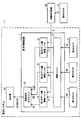
- FIG. 1 is a block diagram showing the configuration of a display control device and a display system.
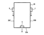
- FIG. 2 is a plan view showing the arrangement of the first camera, the second camera, and the third camera in the host vehicle.
- FIG. 3 is an explanatory diagram showing the relationship between the driver, the display, the line-of-sight direction Z, and the visual field range.
- FIG. 4 is a flowchart showing processing executed by the display control device.
- FIG. 5 is a block diagram showing the configuration of the display control device and the display system
- FIG. 6 is a block diagram illustrating the configuration of the display control device and the display system.
- the display system 3 is an in-vehicle system mounted on a vehicle.
- the vehicle on which the display system 3 is mounted is referred to as the own vehicle.
- the display system 3 includes a display control device 1, a first camera 5, a second camera 7, a third camera 9, a first display device 11, a second display device 13, and a third display device 15.
- a display control device 1 a first camera 5, a second camera 7, a third camera 9, a first display device 11, a second display device 13, and a third display device 15.
- the first display device 11, the second display device 13, and the third display device 15 may be collectively referred to simply as a display device.
- the display control device 1 is a computer including a CPU, a RAM, a ROM, and the like.
- the display control device 1 executes processing to be described later using a program stored in the ROM.
- the display control device 1 functionally includes an arithmetic unit 17, a first data amount adjustment unit 19, a second data amount adjustment unit 21, a third data amount adjustment unit 23, and a video signal output unit 25.
- the arithmetic unit 17 acquires the video signal A0 from the first camera 5, acquires the video signal B0 from the second camera 7, and acquires the video signal C0 from the third camera 9.
- the first camera 5 is attached to the rear end 26 ⁇ / b> A of the host vehicle 26, captures the scenery behind the host vehicle 26, and generates a video signal AO.
- the second camera 7 is attached to the right side surface 26B of the host vehicle 26, and captures a landscape obliquely behind the right side of the host vehicle 26 to generate a video signal BO.
- the third camera 9 is attached to the left side surface 26C of the host vehicle 26, captures a landscape obliquely behind the left side of the host vehicle 26, and generates a video signal CO.
- Each of the video signals A0, B0, and C0 is a video signal having a frame rate (the number of still image frames per unit time) of Ns. Ns is a positive number.
- the arithmetic unit 17 performs a known process such as dynamic range correction on the video signal A0 to generate the video signal A1, and outputs the video signal A1 to the first data amount adjustment unit 19. Similarly, the arithmetic unit 17 executes a known process such as dynamic range correction on the video signal B0 to generate the video signal B1, and outputs the video signal B1 to the second data amount adjustment unit 21. . The arithmetic unit 17 executes a known process such as dynamic range correction on the video signal C0 to generate the video signal C1, and outputs the video signal C1 to the third data amount adjustment unit 23.
- the first data amount adjustment unit 19 adjusts the data amount of the video signal A1 as necessary to generate the video signal A2, and outputs the video signal A2 to the video signal output unit 25.
- the generation of the video signal A2 is performed as follows.
- the first data amount adjustment unit 19 holds data amount adjustment conditions set by processing to be described later.
- the data amount adjustment condition includes a condition that the frame rate of the video signal is maintained at Ns (hereinafter referred to as a data amount maintaining condition) and a condition that the frame rate is reduced to Nd (hereinafter referred to as a data amount reducing condition). )
- Nd is a positive number smaller than Ns.
- the first data amount adjustment unit 19 When the data amount maintenance condition is set, the first data amount adjustment unit 19 generates the video signal A2 having the same frame rate (Ns) as the video signal A1. That is, the video signal A2 is a video signal equal to the video signal A1.
- the first data amount adjustment unit 19 when the data amount reduction condition is set, the first data amount adjustment unit 19 generates a video signal A2 having a frame rate of Nd by thinning out some frames in the video signal A1.
- the data amount of the video signal A2 whose frame rate is Nd is smaller than the data amount of the video signal A2 whose frame rate is Ns.
- the second data amount adjustment unit 21 adjusts the data amount of the video signal B1 as necessary to generate the video signal B2, and outputs the video signal B2 to the video signal output unit 25. That is, the frame rate of the video signal B2 is Ns when the data amount maintenance condition is set in the second data amount adjustment unit 21, and is Nd when the data amount reduction condition is set. The data amount of the video signal B2 whose frame rate is Nd is smaller than the data amount of the video signal B2 whose frame rate is Ns.
- the third data amount adjustment unit 23 adjusts the data amount of the video signal C1 as necessary to generate the video signal C2, and outputs the video signal C2 to the video signal output unit 25. That is, the frame rate of the video signal C2 is Ns when the data amount maintenance condition is set in the third data amount adjustment unit 23, and is Nd when the data amount reduction condition is set. The data amount of the video signal C2 whose frame rate is Nd is smaller than the data amount of the video signal C2 whose frame rate is Ns.
- the video signal output unit 25 outputs the video signals A2, B2, and C2 to the first display device 11.
- the video signal output unit 25, the first display device 11, the second display device 13, and the third display device 15 are connected in the form of a daisy chain.
- the first display device 11 performs display corresponding to the video signal A2. Further, the first display device 11 outputs the video signals B ⁇ b> 2 and C ⁇ b> 2 to the second display device 13.
- the second display device 13 performs display corresponding to the video signal B2. Further, the second display device outputs the video signal C ⁇ b> 2 to the third display device 15.
- the third display device 15 performs display corresponding to the video signal C2.
- the first display device 11, the second display device 13, and the third display device 15 are provided with a liquid crystal display and can display an image.
- the first display device 11, the second display device 13, and the third display device 15 are installed in the passenger compartment of the host vehicle. As shown in FIG. 3, the first display device 11, the second display device 13, and the third display device 15 are spaced apart along the vehicle width direction (the left-right direction in FIG. 3). Installed.
- the first display device 11 is in the front direction
- the second display device 13 is in the right direction
- the third display device 15 is in the left direction.
- the angle ⁇ formed by the direction X and the direction Y is 100 degrees or more. is there. This angle ⁇ is larger than 2 ⁇ which is an angle of a visual field range described later.
- the own vehicle includes a line-of-sight detection device 29 and a fourth camera 31 in addition to the display system 3.
- the fourth camera 31 is installed in the passenger compartment of the host vehicle.
- the fourth camera 31 includes an infrared LED, and irradiates infrared rays to the eyes of the driver.
- the fourth camera 31 shoots the driver's face and generates a video signal D in a state where the infrared rays are irradiated to the driver's eyes.
- the line-of-sight detection device 29 detects the line-of-sight direction Z of the driver shown in FIG.
- the method for detecting the line-of-sight direction Z of the driver is as follows. First, in the video signal D, the position where infrared rays are reflected on the cornea of the driver is recognized. This position is the position of the pupil of the driver. Next, the line-of-sight direction Z of the driver is detected based on the relative position of the pupil with respect to a preset reference position. For example, when the position of the pupil is closer to the head than the reference position, it is determined that the line-of-sight direction Z is the direction toward the eye.
- the line-of-sight detection device 29 outputs the driver's line-of-sight direction Z to the first data amount adjustment unit 19, the second data amount adjustment unit 21, and the third data amount adjustment unit 23.
- the first data amount adjustment unit 19, the second data amount adjustment unit 21, and the third data amount adjustment unit 23 use the line-of-sight direction Z of the driver to determine the data amount adjustment condition. Details will be described later.
- the arithmetic unit 17 is an example of a video signal acquisition unit (also referred to as a video signal acquisition unit).
- the first data amount adjustment unit 19, the second data amount adjustment unit 21, and the third data amount adjustment unit 23 are a gaze direction acquisition unit (also referred to as a gaze direction acquisition unit) and a determination unit (also referred to as a determination unit).
- a data amount adjustment unit also referred to as a data amount adjustment unit).
- a driver is an example of a user.
- the first data amount adjusting unit 19, the second data amount adjusting unit 21, and the third data amount adjusting unit 23 are based on the driver's line-of-sight direction Z acquired in S2, respectively.
- the visual field range of the driver is a range having a spread of an angle ⁇ in the left-right direction around the driver's line-of-sight direction Z.
- the angle ⁇ is an angle in a horizontal plane.
- the value of ⁇ can be set to 15 degrees, for example.
- the width of the visual field range is 30 degrees, which is close to a general human visual field range (an effective visual field with excellent information acceptability).
- the first data amount adjustment unit 19 determines whether or not the first display device 11 is within the visual field range set in S2. Note that the first data amount adjustment unit 19 stores in advance the position of the first display 11 (direction viewed from the driver), and uses the stored position of the first display 11. To make the above judgment. For example, in the example illustrated in FIG. 3, the first display device 11 is within the visual field range.
- the second data amount adjustment unit 21 determines whether or not the second display device 13 is within the visual field range set in S2.
- the second data amount adjustment unit 21 stores in advance the position of the second display device 13 (direction viewed from the driver), and uses the stored position of the second display device 13. To make the above judgment. For example, in the example shown in FIG. 3, the second display device 13 is in the visual field range.
- the third data amount adjustment unit 23 determines whether or not the third display device 15 is within the visual field range set in S2.
- the third data amount adjustment unit 23 stores the position of the third display 15 (direction viewed from the driver) in advance, and uses the stored position of the third display 15. To make the above judgment. For example, in the example shown in FIG. 3, the third display device 15 is out of the visual field range.
- the first data amount adjustment unit 19 sets the data amount adjustment conditions in the first data amount adjustment unit 19 in accordance with the determination result in S3. Specifically, this is performed as follows.
- the data amount maintenance condition is set in the first data amount adjustment unit 19.
- a data amount reduction condition is set in the first data amount adjustment unit 19.
- the second data amount adjustment unit 21 sets the data amount adjustment condition in the second data amount adjustment unit 21 in accordance with the determination result in S3. Specifically, this is performed as follows.
- the data amount maintenance condition is set in the second data amount adjustment unit 21.
- a data amount reduction condition is set in the second data amount adjustment unit 21.
- the third data amount adjustment unit 23 sets data amount adjustment conditions in the third data amount adjustment unit 23 in accordance with the determination result in S3. Specifically, this is performed as follows.
- the data amount maintenance condition is set in the third data amount adjustment unit 23.
- a data amount reduction condition is set in the third data amount adjustment unit 23.
- the display control device 1 sets a data amount reduction condition in the first data amount adjustment unit 19 when the first display device 11 is not within the visual field range. To do. As a result, the data amount of the video signal A2 when the first display device 11 is not within the visual field range is smaller than when the first display device 11 is within the visual field range.
- the display control device 1 sets a data amount reduction condition in the second data amount adjustment unit 21 when the second display device 13 is not within the visual field range.
- the data amount of the video signal B2 when the second display device 13 is not within the visual field range is smaller than when the second display device 13 is within the visual field range.
- the display control device 1 sets a data amount reduction condition in the third data amount adjustment unit 23 when the third display device 15 is not within the visual field range.
- the data amount of the video signal C2 when the third display device 15 is not within the visual field range is smaller than when the third display device 15 is within the visual field range.
- the display control device 1 can suppress the total data amount in the display system 3. In addition, since the display control device 1 does not reduce the data amount of the video signal output to the display device within the visual field range, the video quality of the display device within the visual field range can be maintained.
- the display control device 1 determines whether or not there is a display device within the visual field range for each of the plurality of display devices, and adjusts the data amount of the video signal for each of the plurality of display devices. Therefore, the total data amount in the display system 3 can be further reduced.
- the video signal output unit 25, the first display device 11, the second display device 13, and the third display device 15 are connected in the form of a daisy chain. Therefore, the cable that connects the video signal output unit 25 and the first display 11 transmits the video signals A2, B2, and C2.
- the display control device 1 can suppress the data amount of the video signal as described in (1A)
- the display control device 1 can suppress the data amount of the video signal transmitted through the cable.
- the display control device 1 acquires the line-of-sight direction from the line-of-sight detection device 29 having a function of detecting the line-of-sight direction based on an image obtained by photographing the driver's face. As a result, the direction of the driver's line of sight can be detected easily and accurately.
- (Second Embodiment) 1. Configurations of Display Control Device 1 and Display System 3 The configurations of the display control device 1 and the display system 3 of the present embodiment are basically the same as those of the first embodiment. Below, it demonstrates centering around difference. As shown in FIG. 5, the video signal output unit 25 outputs the video signal A2 to the first display device 11, outputs the video signal B2 to the second display device 13, and displays the video signal C2 in the third display. To the machine 15. That is, the video signal output unit 25, the first display device 11, the second display device 13, and the third display device 15 are connected in a peer-to-peer format.
- the display control device 1 executes processing similar to that of the first embodiment.
- the video signal output unit 25, the first display device 11, the second display device 13, and the third display device 15 are connected in a peer-to-peer format. .
- the amount of data transmitted by the cable connecting the video signal output unit 25 and the first display device 11 can be further reduced.
- (Third embodiment) 1. Configurations of Display Control Device 1 and Display System 3
- the configurations of the display control device 1 and the display system 3 of the present embodiment are basically the same as those of the first embodiment. Below, it demonstrates centering around difference. As shown in FIG. 6, the display system 3 includes a single display device 33.
- the display device 33 divides the screen into three regions 33A, 33B, and 33C, displays an image corresponding to the video signal A2 in the region 33A, and displays an image corresponding to the video signal B2 in the region 33B.
- the video corresponding to the video signal C2 is displayed on 33C.
- the time zone is divided into three, only the video corresponding to the video signal A2 is displayed on the display device 33 in the first time zone, and only the video corresponding to the video signal B2 is displayed in the second time zone, Only the video corresponding to the video signal C2 may be displayed in the third time zone.
- the display control device 1 basically executes the same processing as in the first embodiment. In the present embodiment, since the single display device 33 is provided, in S3, it is determined whether or not the display device 33 is within the visual field range.
- the process of S4 is performed as follows.
- the data amount maintenance condition is set for all of the first data amount adjustment unit 19, the second data amount adjustment unit 21, and the third data amount adjustment unit 23.
- the data amount reduction condition is set for all of the first data amount adjustment unit 19, the second data amount adjustment unit 21, and the third data amount adjustment unit 23.
- the display control device 1 reduces the data amount of the video signals A2, B2, and C2 to be output to the display device 33 when the display device 33 is not within the visual field range than when the display device 33 is within the visual field range. As a result, the total data amount in the display system 3 can be suppressed. Further, when the display device 33 is within the visual field range, the data amount of the video signals A2, B2, and C2 is not reduced, so that the video quality of the display device 33 within the visual field range can be maintained. (Other embodiments) As mentioned above, although embodiment of this indication was described, this indication can take various forms, without being limited to the above-mentioned embodiment.
- the first data amount adjustment unit 19, the second data amount adjustment unit 21, and the third data amount adjustment unit 23 are methods other than the method of thinning out frames.
- the amount of data may be adjusted with. For example, a method such as compressing the video signal or lowering the resolution of the video signal can be used. Two or more methods selected from the plurality of methods described above may be combined.
- the number of display devices is not limited to one or three, and can be set as appropriate.
- the number of display devices can be set to 2, 4, 5, 6, and the like.
- the number of cameras may be the same as or different from the number of display devices.
- videos captured by one camera may be displayed on a plurality of display devices, or videos captured by a plurality of cameras may be displayed on one display device.
- the display system 3 may be a display system installed in a place other than the vehicle, or may be a display system portable by the user.
- the line-of-sight detection device 29 may detect the line of sight of a user other than the driver.
- the line-of-sight direction of the driver may be detected by other methods.
- the face direction may be determined, and the front direction of the face may be set as the line-of-sight direction.
- the magnitude relationship between the data amount of the video signal A1 and the data amount of the video signal A2 when the data amount maintaining condition is set can be set as appropriate.
- the former may be larger than the latter, may be the same, or the former may be smaller than the latter.
- a program for causing a computer to function as the display control device a medium (a computer-readable non-transitory storage medium) on which the program is recorded, a display control method,
- the present disclosure can be realized in various forms such as a video signal data amount control method.
- each step is expressed as, for example, S1. Further, each step can be divided into a plurality of sub-steps, while a plurality of steps can be combined into one step.
Landscapes
- Engineering & Computer Science (AREA)
- Multimedia (AREA)
- Mechanical Engineering (AREA)
- Signal Processing (AREA)
- Fittings On The Vehicle Exterior For Carrying Loads, And Devices For Holding Or Mounting Articles (AREA)
- Closed-Circuit Television Systems (AREA)
- Controls And Circuits For Display Device (AREA)
Abstract
表示制御装置は、映像信号(A0、B0、C0)を取得する映像信号取得ユニット(17)と、映像信号を表示機(11、13、15)に出力する映像信号出力ユニット(25)と、ユーザの視線方向(Z)を取得する視線方向取得ユニットと、視線方向に基づいて設定される視野範囲内に表示機があるか否かを判断する判断ユニットと、視野範囲内に表示機がないと判断した場合は、映像信号のデータ量を調整するデータ量調整ユニットと、を備える。
Description
本出願は、2015年2月12日に出願された日本特許出願2015-25683号に基づいており、その開示は参照により本明細書に組み込まれる。
本開示は表示制御装置及び表示システムに関する。
従来、車両にカメラを搭載し、そのカメラにより取得した映像を車室内の表示機に表示する技術が知られている。カメラで生成した映像信号は、ケーブルにより表示機に伝送される。近年、カメラの高性能化、表示機の高解像度化により、ケーブルで伝送される映像信号のデータ量は増加している。ケーブルの容量に対し、映像信号のデータ量が過大になると、映像信号の伝搬速度が低下してしまう。特許文献1記載の開示は、必要な伝送速度が確保できない場合、映像信号のデータ量を減少させる。
映像信号のデータ量を減少させると、表示機の映像品質が低下することがある。よって、特許文献1記載の開示では、ドライバの視野範囲内にある表示機の映像品質が低下してしまうことがある。
本開示は、映像信号のデータ量を減少させながら、ドライバの視野範囲内にある表示機における映像品質の低下を抑制できる表示制御装置及び表示システムを提供することを目的とする。
本開示の一例による表示制御装置は、映像信号を取得する映像信号取得ユニットと、映像信号を表示機に出力する映像信号出力ユニットと、ユーザの視線方向を取得する視線方向取得ユニットと、視線方向に基づいて設定される視野範囲内に表示機があるか否かを判断する判断ユニットと、視野範囲内に表示機がないと判断した場合は、視野範囲内に表示機があると判断した場合に比べて、その表示機に出力する映像信号のデータ量が小さくなるように映像信号のデータ量を調整するデータ量調整ユニットとを備える。
本開示の別の一例による表示システムは、表示制御装置と、表示機と、映像信号を生成するカメラと、を備える。
本開示の表示制御装置は、表示機がユーザの視野範囲内にない場合、視野範囲内にある場合よりも、その表示機に出力する映像信号のデータ量を小さくする。そのことにより、映像信号のデータ量を減少させることができる。また、表示機がユーザの視野範囲内にある場合、映像信号のデータ量は、表示機がユーザの視野範囲外にある場合より大きいので、その表示機における映像品質を維持することができる。
本開示の表示制御装置および表示システムによれば、映像信号のデータ量を減少させながら、ドライバの視野範囲内にある表示機における映像品質の低下を抑制できる。
本開示についての上記目的および他の目的、特徴や利点は、添付の図面を参照した下記の詳細な説明から、より明確になる。添付図面において
図1は、表示制御装置及び表示システムの構成を表すブロック図であり、
図2は、自車両における第1のカメラ、第2のカメラ、及び第3のカメラの配置を表す平面図であり、
図3は、ドライバ、表示機、視線方向Z、及び視野範囲の関係を表す説明図であり、
図4は、表示制御装置が実行する処理を表すフローチャートであり、
図5は、表示制御装置及び表示システムの構成を表すブロック図であり、
図6は、表示制御装置及び表示システムの構成を表すブロック図である。
本開示の実施形態を図面に基づき説明する。
(第1の実施形態)
1.表示制御装置1及び表示システム3の構成
表示制御装置1及び表示システム3の構成を図1~図3に基づき説明する。表示システム3は、車両に搭載される車載システムである。以下では、表示システム3を搭載する車両を自車両とする。
(第1の実施形態)
1.表示制御装置1及び表示システム3の構成
表示制御装置1及び表示システム3の構成を図1~図3に基づき説明する。表示システム3は、車両に搭載される車載システムである。以下では、表示システム3を搭載する車両を自車両とする。
表示システム3は、表示制御装置1、第1のカメラ5、第2のカメラ7、第3のカメラ9、第1の表示機11、第2の表示機13、及び第3の表示機15を備える。なお、以下では、第1の表示機11、第2の表示機13、及び第3の表示機15を総称して単に表示機と呼ぶこともある。
表示制御装置1は、CPU、RAM、ROM等を備えたコンピュータである。表示制御装置1は、ROMに記憶されたプログラムにより、後述する処理を実行する。表示制御装置1は、機能的に、演算ユニット17、第1のデータ量調整ユニット19、第2のデータ量調整ユニット21、第3のデータ量調整ユニット23、及び映像信号出力ユニット25を備える。
演算ユニット17は、第1のカメラ5から映像信号A0を取得し、第2のカメラ7から映像信号B0を取得し、第3のカメラ9から映像信号C0を取得する。図2に示すように、第1のカメラ5は自車両26の後端26Aに取り付けられており、自車両26の後方の風景を撮影し、映像信号AOを生成する。また、第2のカメラ7は自車両26の右側面26Bに取り付けられており、自車両26の右斜め後方の風景を撮影し、映像信号BOを生成する。また、第3のカメラ9は自車両26の左側面26Cに取り付けられており、自車両26の左斜め後方の風景を撮影し、映像信号COを生成する。映像信号A0、B0、C0はそれぞれ、フレームレート(単位時間あたりの静止画のコマ数)がNsである映像信号である。Nsは正の数である。
演算ユニット17は、映像信号A0に対し、ダイナミックレンジ補正等の周知の処理を実行して映像信号A1を生成し、その映像信号A1を、第1のデータ量調整ユニット19に出力する。同様に、演算ユニット17は、映像信号B0に対し、ダイナミックレンジ補正等の周知の処理を実行して映像信号B1を生成し、その映像信号B1を、第2のデータ量調整ユニット21に出力する。また、演算ユニット17は、映像信号C0に対し、ダイナミックレンジ補正等の周知の処理を実行して映像信号C1を生成し、その映像信号C1を、第3のデータ量調整ユニット23に出力する。
第1のデータ量調整ユニット19は、必要に応じて映像信号A1のデータ量を調整して映像信号A2を生成し、その映像信号A2を映像信号出力ユニット25に出力する。
映像信号A2の生成は、次のように行われる。第1のデータ量調整ユニット19は、後述する処理により設定される、データ量の調整条件を保持している。データ量の調整条件には、映像信号におけるフレームレートをNsのままに保つという条件(以下、データ量維持条件とする)と、フレームレートをNdに落とすという条件(以下、データ量低減条件とする)とがある。ここで、Ndは、Nsより小さい正の数である。
データ量維持条件が設定されている場合、第1のデータ量調整ユニット19は、映像信号A1と同じフレームレート(Ns)を有する映像信号A2を生成する。すなわち、映像信号A2は映像信号A1と等しい映像信号である。
一方、データ量低減条件が設定されている場合、第1のデータ量調整ユニット19は、映像信号A1における一部のフレームを間引くことで、フレームレートがNdである映像信号A2を生成する。フレームレートがNdである映像信号A2のデータ量は、フレームレートがNsである映像信号A2のデータ量より小さい。
同様に、第2のデータ量調整ユニット21は、必要に応じて映像信号B1のデータ量を調整して映像信号B2を生成し、その映像信号B2を映像信号出力ユニット25に出力する。すなわち、映像信号B2のフレームレートは、第2のデータ量調整ユニット21においてデータ量維持条件が設定されている場合はNsであり、データ量低減条件が設定されている場合はNdである。フレームレートがNdである映像信号B2のデータ量は、フレームレートがNsである映像信号B2のデータ量より小さい。
同様に、第3のデータ量調整ユニット23は、必要に応じて映像信号C1のデータ量を調整して映像信号C2を生成し、その映像信号C2を映像信号出力ユニット25に出力する。すなわち、映像信号C2のフレームレートは、第3のデータ量調整ユニット23においてデータ量維持条件が設定されている場合はNsであり、データ量低減条件が設定されている場合はNdである。フレームレートがNdである映像信号C2のデータ量は、フレームレートがNsである映像信号C2のデータ量より小さい。
映像信号出力ユニット25は、映像信号A2、B2、C2を第1の表示機11に出力する。映像信号出力ユニット25、第1の表示機11、第2の表示機13、及び第3の表示機15はデイジーチェーンの形式で接続されている。第1の表示機11は、映像信号A2に対応する表示を行う。また、第1の表示機11は、映像信号B2、C2を第2の表示機13に出力する。第2の表示機13は、映像信号B2に対応する表示を行う。また、第2の表示機は、映像信号C2を第3の表示機15に出力する。第3の表示機15は、映像信号C2に対応する表示を行う。
第1の表示機11、第2の表示機13、及び第3の表示機15は、液晶ディスプレイを備えており、映像を表示可能である。第1の表示機11、第2の表示機13、及び第3の表示機15は、自車両の車室内に設置されている。第1の表示機11、第2の表示機13、及び第3の表示機15は、図3に示すように、自車両の車幅方向(図3における左右方向)に沿って、間隔をおいて設置されている。自車両のドライバ27の視点27Aから見て、第1の表示機11は正面方向にあり、第2の表示機13は右方向にあり、第3の表示機15は左方向にある。視点27Aから第2の表示機13に向う方向を方向Xとし、視点27Aから第3の表示機15に向う方向を方向Yとすると、方向Xと方向Yとが成す角度αは100度以上である。この角度αは、後述する視野範囲の角度である2βより大きい。
自車両は、表示システム3に加えて、視線検知装置29、及び第4のカメラ31を備える。第4のカメラ31は自車両の車室内に設置されている。第4のカメラ31は赤外線LEDを備えており、赤外線をドライバの目に照射する。赤外線をドライバの目に照射した状態で、第4のカメラ31はドライバの顔を撮影し、映像信号Dを生成する。
視線検知装置29は、映像信号Dに基づき、図3に示すドライバの視線方向Zを検知する。ドライバの視線方向Zの検知方法は以下のとおりである。まず、映像信号Dにおいて、赤外線がドライバの角膜上で反射している位置を認識する。この位置は、ドライバの瞳孔の位置である。次に、予め設定された基準位置に対する瞳孔の相対的な位置に基づき、ドライバの視線方向Zを検知する。例えば、瞳孔の位置が基準位置よりも目頭側である場合、視線方向Zは目頭側の方向であると判断する。
視線検知装置29は、ドライバの視線方向Zを、第1のデータ量調整ユニット19、第2のデータ量調整ユニット21、及び第3のデータ量調整ユニット23に出力する。第1のデータ量調整ユニット19、第2のデータ量調整ユニット21、及び第3のデータ量調整ユニット23は、ドライバの視線方向Zを用いて、データ量の調整条件を決定する。詳しくは後述する。
なお、演算ユニット17は、映像信号取得ユニット(映像信号取得部とも呼ぶ)の一例である。また、第1のデータ量調整ユニット19、第2のデータ量調整ユニット21、及び第3のデータ量調整ユニット23は、視線方向取得ユニット(視線方向取得部とも呼ぶ)、判断ユニット(判断部とも呼ぶ)、及びデータ量調整ユニット(データ量調整部とも呼ぶ)の一例である。また、ドライバはユーザの一例である。
2.表示制御装置1が実行する処理
表示制御装置1が所定時間ごとに繰り返し実行する処理を図4に基づき説明する。S1では、第1のデータ量調整ユニット19、第2のデータ量調整ユニット21、及び第3のデータ量調整ユニット23が、それぞれ、視線検知装置29からドライバの視線方向Zを取得する。
表示制御装置1が所定時間ごとに繰り返し実行する処理を図4に基づき説明する。S1では、第1のデータ量調整ユニット19、第2のデータ量調整ユニット21、及び第3のデータ量調整ユニット23が、それぞれ、視線検知装置29からドライバの視線方向Zを取得する。
S2では、第1のデータ量調整ユニット19、第2のデータ量調整ユニット21、及び第3のデータ量調整ユニット23が、それぞれ、前記S2で取得したドライバの視線方向Zに基づき、ドライバの視野範囲を設定する。ドライバの視野範囲とは、図3に示すように、ドライバの視線方向Zを中心とし、左右方向にそれぞれ角度βの広がりを有する範囲である。角度βは、水平面内での角度である。βの値は、例えば、15度とすることができる。この場合、視野範囲の幅は30度となり、人間の一般的な視野範囲(情報受容力に優れる有効視野)と近い値になる。
S3において、第1のデータ量調整ユニット19は、前記S2で設定した視野範囲内に、第1の表示機11があるか否かを判断する。なお、第1のデータ量調整ユニット19は、予め、第1の表示機11の位置(ドライバから見た方向)を記憶しており、その記憶している第1の表示機11の位置を用いて上記の判断を行う。例えば、図3に示す例では、第1の表示機11は視野範囲内にある。
また、第2のデータ量調整ユニット21は、前記S2で設定した視野範囲内に、第2の表示機13があるか否かを判断する。なお、第2のデータ量調整ユニット21は、予め、第2の表示機13の位置(ドライバから見た方向)を記憶しており、その記憶している第2の表示機13の位置を用いて上記の判断を行う。例えば、図3に示す例では、第2の表示機13は視野範囲内にある。
また、第3のデータ量調整ユニット23は、前記S2で設定した視野範囲内に、第3の表示機15があるか否かを判断する。なお、第3のデータ量調整ユニット23は、予め、第3の表示機15の位置(ドライバから見た方向)を記憶しており、その記憶している第3の表示機15の位置を用いて上記の判断を行う。例えば、図3に示す例では、第3の表示機15は視野範囲外にある。
S4において、第1のデータ量調整ユニット19は、前記S3での判断結果に応じて、第1のデータ量調整ユニット19におけるデータ量の調整条件を設定する。具体的には、以下のように行う。
第1の表示機11が視野範囲内である場合は、第1のデータ量調整ユニット19に、データ量維持条件を設定する。一方、第1の表示機11が視野範囲外である場合は、第1のデータ量調整ユニット19に、データ量低減条件を設定する。
また、第2のデータ量調整ユニット21は、前記S3での判断結果に応じて、第2のデータ量調整ユニット21におけるデータ量の調整条件を設定する。具体的には、以下のように行う。
第2の表示機13が視野範囲内である場合は、第2のデータ量調整ユニット21に、データ量維持条件を設定する。一方、第2の表示機13が視野範囲外である場合は、第2のデータ量調整ユニット21に、データ量低減条件を設定する。
また、第3のデータ量調整ユニット23は、前記S3での判断結果に応じて、第3のデータ量調整ユニット23におけるデータ量の調整条件を設定する。具体的には、以下のように行う。
第3の表示機15が視野範囲内である場合は、第3のデータ量調整ユニット23に、データ量維持条件を設定する。一方、第3の表示機15が視野範囲外である場合は、第3のデータ量調整ユニット23に、データ量低減条件を設定する。
なお、上記のように設定したデータ量の調整条件は、後に、データ量の調整条件を設定し直すまで維持される。
3.表示制御装置1及び表示システム3が奏する効果
(1A)表示制御装置1は、第1の表示機11が視野範囲内にない場合、第1のデータ量調整ユニット19に、データ量低減条件を設定する。その結果、第1の表示機11が視野範囲内にない場合における映像信号A2のデータ量は、第1の表示機11が視野範囲内にある場合よりも小さくなる。
(1A)表示制御装置1は、第1の表示機11が視野範囲内にない場合、第1のデータ量調整ユニット19に、データ量低減条件を設定する。その結果、第1の表示機11が視野範囲内にない場合における映像信号A2のデータ量は、第1の表示機11が視野範囲内にある場合よりも小さくなる。
また、表示制御装置1は、第2の表示機13が視野範囲内にない場合、第2のデータ量調整ユニット21に、データ量低減条件を設定する。その結果、第2の表示機13が視野範囲内にない場合における映像信号B2のデータ量は、第2の表示機13が視野範囲内にある場合よりも小さくなる。
また、表示制御装置1は、第3の表示機15が視野範囲内にない場合、第3のデータ量調整ユニット23に、データ量低減条件を設定する。その結果、第3の表示機15が視野範囲内にない場合における映像信号C2のデータ量は、第3の表示機15が視野範囲内にある場合よりも小さくなる。
よって、表示制御装置1は、表示システム3における総データ量を抑制することができる。また、表示制御装置1は、視野範囲内にある表示機に出力する映像信号のデータ量は小さくしないので、視野範囲内にある表示機の映像品質を維持することができる。
(1B)表示制御装置1は、複数の表示機のそれぞれについて、視野範囲内に表示機があるか否かを判断し、複数の表示機のそれぞれについて、映像信号のデータ量を調整する。そのため、表示システム3における総データ量を一層低減することができる。
(1C)映像信号出力ユニット25、第1の表示機11、第2の表示機13、及び第3の表示機15はデイジーチェーンの形式で接続されている。そのため、映像信号出力ユニット25と第1の表示機11とを接続するケーブルは、映像信号A2、B2、C2を伝送する。しかしながら、表示制御装置1は、前記(1A)のとおり、映像信号のデータ量を抑制できるので、前記のケーブルにより伝送する映像信号のデータ量を抑制できる。
(1D)表示制御装置1は、ドライバの顔を撮影した映像に基づき視線方向を検知する機能を有する視線検知装置29から視線方向を取得する。そのことにより、ドライバの視線方向を容易且つ正確に検知することができる。
(第2の実施形態)
1.表示制御装置1及び表示システム3の構成
本実施形態の表示制御装置1及び表示システム3の構成は、基本的には前記第1の実施形態と同様である。以下では、相違点を中心に説明する。図5に示すように、映像信号出力ユニット25は、映像信号A2を第1の表示機11に出力し、映像信号B2を第2の表示機13に出力し、映像信号C2を第3の表示機15に出力する。すなわち、映像信号出力ユニット25、第1の表示機11、第2の表示機13、及び第3の表示機15は、ピアツーピア(Peer to Peer)の形式で接続されている。
(第2の実施形態)
1.表示制御装置1及び表示システム3の構成
本実施形態の表示制御装置1及び表示システム3の構成は、基本的には前記第1の実施形態と同様である。以下では、相違点を中心に説明する。図5に示すように、映像信号出力ユニット25は、映像信号A2を第1の表示機11に出力し、映像信号B2を第2の表示機13に出力し、映像信号C2を第3の表示機15に出力する。すなわち、映像信号出力ユニット25、第1の表示機11、第2の表示機13、及び第3の表示機15は、ピアツーピア(Peer to Peer)の形式で接続されている。
2.表示制御装置1が実行する処理
本実施形態の表示制御装置1は、前記第1の実施形態と同様の処理を実行する。
本実施形態の表示制御装置1は、前記第1の実施形態と同様の処理を実行する。
3.表示制御装置1及び表示システム3が奏する効果
以上詳述した第2の実施形態によれば、前述した第1の実施形態の効果(1A)、(1B)、(1D)に加え、以下の効果が得られる。
以上詳述した第2の実施形態によれば、前述した第1の実施形態の効果(1A)、(1B)、(1D)に加え、以下の効果が得られる。
(2A)本実施形態では、映像信号出力ユニット25、第1の表示機11、第2の表示機13、及び第3の表示機15は、ピアツーピア(Peer to Peer)の形式で接続されている。そのことにより、映像信号出力ユニット25と第1の表示機11とを接続するケーブルが伝送するデータ量を一層低減できる。
(第3の実施形態)
1.表示制御装置1及び表示システム3の構成
本実施形態の表示制御装置1及び表示システム3の構成は、基本的には前記第1の実施形態と同様である。以下では、相違点を中心に説明する。図6に示すように、表示システム3は、単一の表示機33を備える。表示機33は、画面を3つの領域33A、33B、33Cに分割し、領域33Aには映像信号A2に対応する映像を表示し、領域33Bには映像信号B2に対応する映像を表示し、領域33Cには映像信号C2に対応する映像を表示する。
(第3の実施形態)
1.表示制御装置1及び表示システム3の構成
本実施形態の表示制御装置1及び表示システム3の構成は、基本的には前記第1の実施形態と同様である。以下では、相違点を中心に説明する。図6に示すように、表示システム3は、単一の表示機33を備える。表示機33は、画面を3つの領域33A、33B、33Cに分割し、領域33Aには映像信号A2に対応する映像を表示し、領域33Bには映像信号B2に対応する映像を表示し、領域33Cには映像信号C2に対応する映像を表示する。
あるいは、時間帯を3つに区切り、1番目の時間帯では映像信号A2に対応する映像のみを表示機33に表示し、2番目の時間帯では映像信号B2に対応する映像のみを表示し、3番目の時間帯では映像信号C2に対応する映像のみを表示してもよい。
2.表示制御装置1が実行する処理
本実施形態の表示制御装置1は、基本的には前記第1の実施形態と同様の処理を実行する。本実施形態では、単一の表示機33を備えるので、前記S3では、表示機33が視野範囲内であるか否かを判断する。
本実施形態の表示制御装置1は、基本的には前記第1の実施形態と同様の処理を実行する。本実施形態では、単一の表示機33を備えるので、前記S3では、表示機33が視野範囲内であるか否かを判断する。
また、前記S4の処理は、以下のようにする。表示機33が視野範囲内である場合は、第1のデータ量調整ユニット19、第2のデータ量調整ユニット21、及び第3のデータ量調整ユニット23の全てに、データ量維持条件を設定する。一方、表示機33が視野範囲外である場合は、第1のデータ量調整ユニット19、第2のデータ量調整ユニット21、及び第3のデータ量調整ユニット23の全てに、データ量低減条件を設定する。
3.表示制御装置1及び表示システム3が奏する効果
以上詳述した第3の実施形態によれば、前述した第1の実施形態の効果(1D)に加え、以下の効果が得られる。
以上詳述した第3の実施形態によれば、前述した第1の実施形態の効果(1D)に加え、以下の効果が得られる。
(3A)表示制御装置1は、表示機33が視野範囲内にない場合、視野範囲内にある場合よりも、表示機33に出力する映像信号A2、B2、C2のデータ量を小さくする。そのことにより、表示システム3における総データ量を抑制することができる。また、表示機33が視野範囲内にある場合、映像信号A2、B2、C2のデータ量は小さくしないので、視野範囲内にある表示機33の映像品質を維持することができる。
(その他の実施形態)
以上、本開示の実施形態について説明したが、本開示は上記実施形態に限定されることなく、種々の形態を採り得る。
(その他の実施形態)
以上、本開示の実施形態について説明したが、本開示は上記実施形態に限定されることなく、種々の形態を採り得る。
(1)前記第1~第3の実施形態において、第1のデータ量調整ユニット19、第2のデータ量調整ユニット21、及び第3のデータ量調整ユニット23は、フレームを間引く方法以外の方法でデータ量を調整してもよい。例えば、映像信号を圧縮する、映像信号の解像度を低くする等の方法を使用できる。また、上述した複数の方法から選択した2以上の方法を組み合わせてもよい。
(2)前記第1~第3の実施形態において、表示機の数は、1個、3個には限定されず、適宜設定することができる。例えば、表示機の数を2、4、5、6個などとすることができる。
(3)前記第1~第3の実施形態において、カメラの数は、表示機の数と同じであってもよいし、異なっていてもよい。例えば、1つのカメラで撮影した映像を、複数の表示機に表示してもよいし、複数のカメラで撮影した映像を、1つの表示機に表示してもよい。
(4)前記第1~第3の実施形態において、表示システム3は、車両以外の場所に設置される表示システムであってもよいし、ユーザが携帯可能な表示システムであってもよい。また、視線検知装置29は、ドライバ以外のユーザの視線を検知するものであってもよい。
(5)前記第1~第3の実施形態において、他の方法でドライバの視線方向を検知してもよい。例えば、第4のカメラ31で取得した映像において、顔の向きを判断し、顔の正面方向を視線方向としてもよい。
(6)前記第1~第3の実施形態において、映像信号A1のデータ量と、データ量維持条件が設定されている場合の映像信号A2のデータ量との大小関係は適宜設定することができる。例えば、前者が後者より大きくてもよいし、同じであってもよいし、前者が後者より小さくてもよい。
(7)上記実施形態における1つの構成要素が有する機能を複数の構成要素として分散させたり、複数の構成要素が有する機能を1つの構成要素に統合させたりしてもよい。また、上記実施形態の構成の一部を省略してもよい。また、上記実施形態の構成の少なくとも一部を、他の上記実施形態の構成に対して付加又は置換してもよい。なお、本開示に記載した文言のみによって特定される技術思想に含まれるあらゆる態様が本開示の実施形態である。
(8)上述した表示制御装置、表示システムの他、当該表示制御装置としてコンピュータを機能させるためのプログラム、このプログラムを記録した媒体(コンピュータ読み取り可能な非一時的な記憶媒体)、表示制御方法、映像信号のデータ量制御方法等、種々の形態で本開示を実現することもできる。
ここで、この出願に記載されるフローチャート、あるいは、フローチャートの処理は、複数のステップ(あるいはセクションと言及される)から構成され、各ステップは、たとえば、S1と表現される。さらに、各ステップは、複数のサブステップに分割されることができる、一方、複数のステップが合わさって一つのステップにすることも可能である。
以上、本開示に係る表示制御装置及び表示システムの実施形態、構成、態様を例示したが、本開示に係る実施形態、構成、態様は、上述した各実施形態、各構成、各態様に限定されるものではない。例えば、異なる実施形態、構成、態様にそれぞれ開示された技術的部を適宜組み合わせて得られる実施形態、構成、態様についても本開示に係る実施形態、構成、態様の範囲に含まれる。
Claims (6)
- 映像信号(A0、B0、C0)を取得する映像信号取得ユニット(17)と、
前記映像信号を表示機(11、13、15)に出力する映像信号出力ユニット(25)と、
ユーザの視線方向(Z)を取得する視線方向取得ユニット(19、21、23)と、
前記視線方向に基づいて設定される視野範囲内に前記表示機があるか否かを判断する判断ユニット(19、21、23)と、
前記視野範囲内に前記表示機がないと判断した場合は、前記視野範囲内に前記表示機があると判断した場合に比べて、前記表示機に出力する前記映像信号のデータ量が小さくなるように前記映像信号のデータ量を調整するデータ量調整ユニット(19、21、23)と、
を備える表示制御装置。 - 請求項1に記載の表示制御装置であって、
前記映像信号出力ユニットは、複数の前記表示機のそれぞれについて、前記映像信号を出力し、
前記判断ユニットは、複数の前記表示機のそれぞれについて、前記視野範囲内に前記表示機があるか否かを判断し、
前記データ量調整ユニットは、複数の前記表示機のそれぞれについて、前記判断ユニットの判断結果に基づき、前記映像信号のデータ量を調整する表示制御装置。 - 請求項2に記載の表示制御装置であって、
前記映像信号出力ユニット及び複数の前記表示機は、デイジーチェーンの形式で接続されている表示制御装置。 - 請求項1~3のいずれか1項に記載の表示制御装置であって、
前記視線方向取得ユニットは、ユーザの顔を撮影した映像に基づき前記視線方向を検知する機能を有する視線検知装置(29)から前記視線方向を取得する表示制御装置。 - 請求項1~4のいずれか1項に記載の表示制御装置であって、
前記データ量調整ユニットは、
(a)前記映像信号のフレームを間引くこと、
(b)前記映像信号を圧縮すること、及び
(c)前記映像信号の解像度を低くすること、から選択される1以上の方法で、前記映像信号のデータ量を小さくする表示制御装置。 - 請求項1~5のいずれか1項に記載の表示制御装置と、前記表示機と、前記映像信号を生成するカメラ(5、7、9)と、を備える表示システム。
Applications Claiming Priority (2)
| Application Number | Priority Date | Filing Date | Title |
|---|---|---|---|
| JP2015025683A JP2016149651A (ja) | 2015-02-12 | 2015-02-12 | 表示制御装置及び表示システム |
| JP2015-025683 | 2015-02-12 |
Publications (1)
| Publication Number | Publication Date |
|---|---|
| WO2016129241A1 true WO2016129241A1 (ja) | 2016-08-18 |
Family
ID=56614509
Family Applications (1)
| Application Number | Title | Priority Date | Filing Date |
|---|---|---|---|
| PCT/JP2016/000523 Ceased WO2016129241A1 (ja) | 2015-02-12 | 2016-02-02 | 表示制御装置及び表示システム |
Country Status (2)
| Country | Link |
|---|---|
| JP (1) | JP2016149651A (ja) |
| WO (1) | WO2016129241A1 (ja) |
Cited By (1)
| Publication number | Priority date | Publication date | Assignee | Title |
|---|---|---|---|---|
| CN109937158A (zh) * | 2016-12-27 | 2019-06-25 | 金泰克斯公司 | 具有眼睛跟踪的后视系统 |
Citations (3)
| Publication number | Priority date | Publication date | Assignee | Title |
|---|---|---|---|---|
| JP2003153263A (ja) * | 2001-11-19 | 2003-05-23 | Hitachi Ltd | 映像表示システムおよびその方法 |
| WO2005124735A1 (ja) * | 2004-06-18 | 2005-12-29 | Nec Corporation | 画像表示システム、画像表示方法および画像表示プログラム |
| JP2012095229A (ja) * | 2010-10-28 | 2012-05-17 | Sharp Corp | 画像表示装置及び画像表示装置用のコンピュータプログラム |
-
2015
- 2015-02-12 JP JP2015025683A patent/JP2016149651A/ja active Pending
-
2016
- 2016-02-02 WO PCT/JP2016/000523 patent/WO2016129241A1/ja not_active Ceased
Patent Citations (3)
| Publication number | Priority date | Publication date | Assignee | Title |
|---|---|---|---|---|
| JP2003153263A (ja) * | 2001-11-19 | 2003-05-23 | Hitachi Ltd | 映像表示システムおよびその方法 |
| WO2005124735A1 (ja) * | 2004-06-18 | 2005-12-29 | Nec Corporation | 画像表示システム、画像表示方法および画像表示プログラム |
| JP2012095229A (ja) * | 2010-10-28 | 2012-05-17 | Sharp Corp | 画像表示装置及び画像表示装置用のコンピュータプログラム |
Cited By (4)
| Publication number | Priority date | Publication date | Assignee | Title |
|---|---|---|---|---|
| CN109937158A (zh) * | 2016-12-27 | 2019-06-25 | 金泰克斯公司 | 具有眼睛跟踪的后视系统 |
| KR20190102184A (ko) * | 2016-12-27 | 2019-09-03 | 젠텍스 코포레이션 | 눈 추적을 구비한 후방 비전 시스템 |
| JP2020515449A (ja) * | 2016-12-27 | 2020-05-28 | ジェンテックス コーポレイション | アイトラッキングを備えたリアビジョンシステム |
| KR102464874B1 (ko) * | 2016-12-27 | 2022-11-09 | 젠텍스 코포레이션 | 눈 추적을 구비한 후방 비전 시스템 |
Also Published As
| Publication number | Publication date |
|---|---|
| JP2016149651A (ja) | 2016-08-18 |
Similar Documents
| Publication | Publication Date | Title |
|---|---|---|
| US8564645B2 (en) | Signal processing device, image display device, signal processing method, and computer program | |
| US9007442B2 (en) | Stereo image display system, stereo imaging apparatus and stereo display apparatus | |
| JPWO2017183346A1 (ja) | 情報処理装置、情報処理方法、及びプログラム | |
| WO2015064080A1 (ja) | 視線方向検出装置および視線方向検出方法 | |
| JP2013168063A (ja) | 画像処理装置、画像表示システム及び画像処理方法 | |
| WO2018047400A1 (ja) | 車両用表示制御装置、車両用表示システム、車両用表示制御方法およびプログラム | |
| CN111264057B (zh) | 信息处理装置、信息处理方法和记录介质 | |
| US11034305B2 (en) | Image processing device, image display system, and image processing method | |
| CN106494309A (zh) | 车辆的视觉盲区的画面显示方法、装置以及车载虚拟系统 | |
| JP2018148314A (ja) | 俯瞰映像生成装置、俯瞰映像生成システム、俯瞰映像生成方法およびプログラム | |
| US10438402B2 (en) | Image processing apparatus, image processing system, image processing method, and storage medium | |
| WO2018042976A1 (ja) | 画像生成装置、画像生成方法、記録媒体、および画像表示システム | |
| JP2018121287A (ja) | 車両用表示制御装置、車両用表示システム、車両用表示制御方法およびプログラム | |
| JP2019102936A (ja) | 表示装置、電子ミラー、表示装置の制御方法、および表示制御プログラム | |
| US8983125B2 (en) | Three-dimensional image processing device and three dimensional image processing method | |
| WO2016129241A1 (ja) | 表示制御装置及び表示システム | |
| US12407805B2 (en) | Image capturing apparatus for capturing a plurality of eyeball images, image capturing method for image capturing apparatus, and storage medium | |
| JP2017215447A (ja) | 表示制御装置および表示制御方法 | |
| JP2024118122A (ja) | 情報処理装置、情報処理方法、及びプログラム | |
| JP6488628B2 (ja) | 映像処理装置、及び車載映像処理システム | |
| JP2018113622A (ja) | 画像処理装置、画像処理システム、及び、画像処理方法 | |
| US20250069209A1 (en) | Image processing device | |
| JP6766433B2 (ja) | 車両用表示制御装置、車両用表示システム、車両用表示制御方法およびプログラム | |
| JP6136747B2 (ja) | 2次元3次元表示装置 | |
| US20150054822A1 (en) | Image processing device, image processing method, and program |
Legal Events
| Date | Code | Title | Description |
|---|---|---|---|
| 121 | Ep: the epo has been informed by wipo that ep was designated in this application |
Ref document number: 16748888 Country of ref document: EP Kind code of ref document: A1 |
|
| NENP | Non-entry into the national phase |
Ref country code: DE |
|
| 122 | Ep: pct application non-entry in european phase |
Ref document number: 16748888 Country of ref document: EP Kind code of ref document: A1 |