WO2016125667A1 - ガラス製造用スターラー - Google Patents
ガラス製造用スターラー Download PDFInfo
- Publication number
- WO2016125667A1 WO2016125667A1 PCT/JP2016/052440 JP2016052440W WO2016125667A1 WO 2016125667 A1 WO2016125667 A1 WO 2016125667A1 JP 2016052440 W JP2016052440 W JP 2016052440W WO 2016125667 A1 WO2016125667 A1 WO 2016125667A1
- Authority
- WO
- WIPO (PCT)
- Prior art keywords
- stirrer
- blade
- shaft
- glass
- socket
- Prior art date
- Legal status (The legal status is an assumption and is not a legal conclusion. Google has not performed a legal analysis and makes no representation as to the accuracy of the status listed.)
- Ceased
Links
Images




Classifications
-
- C—CHEMISTRY; METALLURGY
- C03—GLASS; MINERAL OR SLAG WOOL
- C03B—MANUFACTURE, SHAPING, OR SUPPLEMENTARY PROCESSES
- C03B5/00—Melting in furnaces; Furnaces so far as specially adapted for glass manufacture
- C03B5/16—Special features of the melting process; Auxiliary means specially adapted for glass-melting furnaces
- C03B5/18—Stirring devices; Homogenisation
- C03B5/187—Stirring devices; Homogenisation with moving elements
Definitions
- the present invention relates to a stirrer for producing glass for stirring and homogenizing molten glass. Specifically, the present invention relates to a stirrer for glass production that can stir molten glass with high efficiency and is excellent in durability.
- the glass material that has been adjusted and mixed is melted, and the glass in the molten state is homogenized and the refractive index is homogenized by stirring the molten glass, and then molded into glass. It is a product.
- This stirring step is a particularly important step in the glass production process under the circumstances where a glass product that is homogeneous and free of defects (such as striae and bubbles) is desired.
- a stirrer for glass production is configured by installing a stirrer blade (hereinafter sometimes simply referred to as a blade) as a stirring blade on a stirrer shaft (hereinafter simply referred to as a shaft) that serves as a rotating shaft.
- a stirrer blade hereinafter sometimes simply referred to as a blade
- a stirrer shaft hereinafter simply referred to as a shaft
- Patent Document 1 describes a glass production stirrer in which a rod-like blade is fixed to a stirrer shaft by penetrating it and installed in multiple stages.
- Patent Document 2 describes a glass production stirrer in which two sets of rod-shaped blades protruding on both sides around a stirrer shaft are fixed so as to intersect.
- the performance preferentially required for a glass production stirrer is to exhibit an effective stirring action so that a suitable flow state can be imparted to the molten glass and homogenization can be achieved.
- glasses with various properties have been developed to meet various applications and requirements. Among them, many glasses have a high viscosity in the molten state, and it is required to arrange a blade so that an effective stirring action can be exerted even on such a high-viscosity molten glass.
- the stirrers for glass production are required to have durability as equipment.
- Molten glass is a fluid having a high temperature of 1000 ° C. or higher, and a glass production stirrer for treating the molten glass is exposed to a severe use environment.
- the load applied to the blade is considerably large, and there is a concern about durability due to the high viscosity of the molten glass.
- this invention aims at providing the stirrer for glass manufacture which is excellent in durability and cannot produce a breakage easily, exhibiting the stirring effect
- the present invention for solving the above-mentioned problems is a glass production stirrer comprising a hollow pipe-shaped stirrer shaft and at least two stirrer blades fixed through the stirrer shaft, wherein the at least two stirrers are provided. At least one stirrer blade of the blade passes through the stirrer shaft in a divided state, and the at least two stirrer blades are fixed so as to intersect near the center line of the stirrer shaft,
- a stirrer for glass production characterized in that the stirrer shaft includes a socket that has an outer shape in which at least two cylindrical bodies intersect each other and surrounds the stirrer blade inside the stirrer shaft.
- a part or all of the blades are divided and passed through the shaft, thereby eliminating the mutual interference of the blades and crossing them.
- the ends of the divided blades are in a free state, so that the fixing is insufficient. Therefore, by setting a socket for holding the intersecting blade inside the shaft, a plurality of intersecting blades are integrated to stabilize the shaft.
- the stirrer for glass production according to the present invention will be described in more detail.
- the present invention is characterized by the configuration of the socket installed in the shaft and the arrangement relationship of the blades.
- the socket has an outer shape in which at least two cylinders intersect and communicate with each other at the intersection.
- intersection state can be formed by inserting and hold
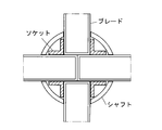
- FIG. 1 is a specific example of a socket, and a blade can be inserted into the opening of the socket to form a crossed blade (FIG. 2).
- the blades can be evenly fixed by notching the tip portions of the divided stirrer blades to form a processed surface. As shown in FIG. 3, a split blade having a machining surface is inserted, and the machining surfaces of the respective stirrer blades are crossed in the vicinity of the intersecting portion of the socket, so that a constraining force by the socket is added and an integral blade is formed. Is done.
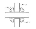
- blade division all the blades may be divided as described above (FIG. 3), but one blade without division can be partially used. At this time, one stirrer blade is inserted and held through one of the cylindrical bodies of the socket, and the divided stirrer blade is inserted and held from both ends of the other cylindrical body ( FIG. 4).
- a single stirrer blade can be passed through and held in the first cylinder, and the stirrer blade divided into the second cylinder can be inserted and held (FIG. 6).
- the present invention can provide a belt-shaped reinforcing ring that abuts against the inner wall surface of the stirrer shaft and has a through hole at a position corresponding to the end of the cylindrical body of the socket. With this reinforcing ring, the blade can be more stably fixed (FIG. 7).
- the stirrer for producing glass according to the present invention is characterized in that the socket and the reinforcing ring described above are provided inside the shaft, whereby the blades are appropriately arranged, and other configurations are the same as those of the conventional stirrer. .
- the constituent material of the blade is preferably a platinum-based material such as platinum, platinum alloy, reinforced platinum, or reinforced platinum alloy. This is because it is preferable to apply a high-melting-point material excellent in chemical stability in order to process a high-melting-point molten glass.
- platinum-based material include pure platinum and platinum alloys such as platinum-rhodium alloys (for example, platinum-5 to 30% by weight rhodium alloy) or platinum-gold alloys (for example, platinum-5% by weight gold alloy).
- reinforced platinum or reinforced platinum alloy is a dispersion strengthened alloy in which a metal oxide is dispersed in platinum or a platinum alloy.
- This reinforced platinum or reinforced platinum alloy is more suitable as a structural material for a glass manufacturing apparatus used in a high temperature environment because it has excellent high temperature strength characteristics, particularly high temperature creep strength.
- Preferred dispersed particles of reinforced platinum or reinforced platinum alloy are refractory valve metal oxides such as zirconium oxide and yttrium oxide, and rare earth metal oxides such as samarium oxide.
- the dispersed particles preferably have a particle size of less than 1 ⁇ m, particularly about several tens of nanometers, and the amount of the dispersed particles is preferably several weight% or less.
- the matrix may be platinum or platinum-rhodium alloy (for example, platinum-5 to 30 wt% rhodium alloy) or platinum-gold alloy (for example, platinum-5 wt% gold alloy) as platinum alloy. preferable.
- the configuration of the blade is preferably a rod shape, and preferably a hollow pipe shape in consideration of light weight and material cost.
- the blade is a hollow cylindrical body formed by winding a flat plate made of the above-mentioned platinum-based material and seam-welding two opposing sides, and a circular cylinder formed by welding the disk made of the same material to both ends of the cylinder. Often served as. In this case, the plate thickness is preferably 1.5 mm or more.
- the constituent material of the socket is preferably platinum, platinum alloy, reinforced platinum, or reinforced platinum alloy. The same applies to the reinforcing ring.
- the constituent material of the shaft that functions as the rotating shaft of the blade is preferably a platinum-based material (platinum, platinum alloy, reinforced platinum, reinforced platinum alloy) as in the case of the blade.
- the ratio (Db / Ds) between the diameter (Db) and the diameter (Ds) of the stirrer shaft is preferably 1/3 or less.
- Db / Ds exceeds 1/3 (when the blade diameter is large), there is a danger that the diameter of the hole in the shaft increases and the strength of the shaft decreases.
- the lower limit of Db / Ds does not need to be set specifically, but is preferably 1/10 from a practical viewpoint such as a stirring action.
- the number of blades is not limited. It is not limited to what the two blades penetrating the shaft intersect so far.
- a stirrer having three or more blades penetrated (FIG. 8). Preferably, 2 to 4 blades cross each other. Further, the blade may penetrate horizontally with respect to the shaft, but may be inclined. Further, the crossing angle between the blades is not limited.
- the blade is installed in a plurality of stages. That is, it is preferable that at least two stirrer blades intersecting substantially on the center line of the stirrer shaft are one set of blade groups, and one or more sets of blade groups are fixed to the stirrer shaft in multiple stages.
- the number of stages is preferably 2 to 10 stages. In one stage, the stirring action is weak, and those exceeding 10 stages are excluded from the viewpoint of material cost.
- the number of stages is set in consideration of the size (depth) of the stirring tank.
- the blade that penetrates the shaft is preferably welded at the base of the shaft. This is to provide a seal that prevents the molten glass from entering the shaft. Welding also has the effect of complementarily fixing the blade. However, since the heat-affected zone formed by welding as described above is in an unfavorable state in terms of strength, the welding of the blade is sufficient for welding the blade so as to seal the gap with the shaft.
- the glass production stirrer according to the present invention has an optimal balance between the arrangement state of the blade and the fixed strength, and various conventional stirrers are used when stirring high-viscosity molten glass. In addition to having a higher stirring action, durability is also ensured.
- the figure explaining an example of the socket for blade fixation used by this invention The figure explaining an example of the braid
- the figure explaining the example of the blade fixation by the socket of FIG. The figure explaining the example of application of a reinforcement ring.
- FIG. 9 is an external view of the stirrer for glass production produced in the present embodiment.
- This stirrer for glass production is one in which two rod-shaped blades orthogonal to each other are set on a stirrer shaft made of a hollow pipe.
- the blade is a pipe manufactured by winding a reinforced platinum alloy plate having a thickness of 1.5 mm and seam welding the butt portion (thickness 1.5 mm, diameter 20 mm, length 200 mm).
- This reinforced platinum is platinum in which zirconium oxide is dispersed using a platinum-10% rhodium alloy (trade name: nanoplat (registered trademark), manufactured by Tanaka Kikinzoku Kogyo) as a matrix.
- the stirrer shaft is made of the same reinforced platinum hollow pipe (thickness 2.0 mm, diameter 60 mm, length 500 mm). A hole (diameter 21 mm) for penetrating the blade is drilled in the shaft.
- ⁇ A blade with the same structure as the socket shown in Fig. 5 is used to fix the blade to the shaft.
- the blade was fixed in such a manner that the socket opening and the shaft hole were aligned with each other, and after the socket was built in the shaft, the blades were sequentially inserted and connected (FIG. 6). Then, the base of the blade joint portion on the outer surface of the shaft was joined by seam welding. At this time, with respect to the cross section of the blade in the welded portion, the heat input was adjusted so that the depth of the heat affected zone was 1.2 mm or less. The interval between the lower blade and the upper blade is 150 mm.
- simulation of molten glass stirring was performed to confirm the stirring action.
- commercially available simulation software (trade name: ANSYS CFD, manufactured by Ansys Japan) was used. This simulation is to analyze the Mises stress distribution in the stirrer when one stirrer is installed in the stirring tank and the molten glass flow is stirred.
- the simulation conditions were a molten glass flow temperature: 1400 ° C., a glass viscosity of 100 Pa ⁇ s, and a stirrer rotation speed of 20 rpm.
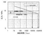
- the life of each stirrer was referenced based on the high temperature creep curve (stress-rupture time diagram) for the reinforced platinum alloy applied in this embodiment. As a result, assuming that the life of the comparative example is 1 year, the life of the stirrer of this embodiment is about 9 years, and it has been found that there is a significant effect of improving the life.
- the stirrer for producing a glass according to the present invention has a high stirring action even when stirring high-viscosity molten glass and has excellent durability.
- the invention can be used in particular for the production of glass panes for LCDs, OLEDs or plasma displays, and for the homogenization of glass melts in glass products such as glass ceramics, borosilicate glasses, optical glasses, glass tubes.
Landscapes
- Chemical & Material Sciences (AREA)
- Engineering & Computer Science (AREA)
- Materials Engineering (AREA)
- Organic Chemistry (AREA)
- Mixers Of The Rotary Stirring Type (AREA)
Abstract
本発明は、中空パイプ状のスターラーシャフトと、前記スターラーシャフトを貫通して固定される少なくとも2本のスターラーブレードと、を備えるガラス製造用のスターラーにおいて、前記少なくとも2本のスターラーブレードの少なくとも1のスターラーブレードは、分割された状態で前記スターラーシャフトを貫通しており、前記少なくとも2本のスターラーブレードが、前記スターラーシャフトの中心線付近で交差するようにして固定されており、前記スターラーシャフトの内部に、少なくとも2本の筒体が交差した外形を有し、スターラーシャフト内部のスターラーブレードを包囲しつつ保持するソケットを備えることを特徴とするガラス製造用のスターラーである。本発明のガラス製造用のスターラーは、効率的な溶融ガラスの攪拌作用を有しつつ、耐久性に優れ破損し難い。
Description
本発明は、溶融状態のガラスを攪拌・均質化するためのガラス製造用スターラーに関する。詳しくは、高効率で溶融ガラスの攪拌が可能であり、且つ、耐久性に優れたガラス製造用スターラーに関する。
各種ガラス製品の製造工程においては、調整・混合されたガラス原料を溶融し、溶融状態のガラスを攪拌することによりその成分の均質化、屈折率の均一化を行った後、成型をしてガラス製品としている。均質で欠陥(脈理や泡等)のないガラス製品が求められている状況下において、この攪拌工程はガラス製造工程において特に重要な工程である。
溶融ガラスの攪拌は、溶融ガラス槽にガラス製造用スターラーを挿入して回転させることにより行われる。ガラス製造用スターラーは、回転軸となるスターラーシャフト(以下、単にシャフトと称することがある)に、攪拌翼となるスターラーブレード(以下、単にブレードと称することがある)を設置して構成される。例えば、特許文献1には、スターラーシャフトに棒状ブレードを貫通して固定し、これを多段に設置したガラス製造用スターラーが記載されている。また、特許文献2では、スターラーシャフトを軸として双方に突出した棒状ブレードを2組交差するように固定したガラス製造用スターラーが記載されている。
ガラス製造用スターラーに優先的に要求される性能としては、溶融ガラスに好適な流動状態を付与して均質化を図ることができるように、効果的な攪拌作用を発揮することである。近年においては、多様な用途・要求に対応するため様々な特性のガラスが開発されている。その中には、溶融状態において高粘度となるガラスも多く、そのような高粘度の溶融ガラスに対しても効果的な攪拌作用を発揮できるように、ブレードを配置することが求められる。
また、ガラス製造用スターラーには、設備機器としての耐久性も要求される。溶融ガラスは1000℃以上の高温の流体であり、これを処理するガラス製造用スターラーは過酷な使用環境下に晒される。特に、ブレードにかかる負荷は相当に大きいものであり、溶融ガラスの高粘度化も相俟って耐久性が懸念されるところである。
以上のような攪拌作用の強化や耐久性確保の課題については、これまで知られているガラス製造用スターラーでも考慮されているが、改善の余地がいまだあるといえる。そこで本発明は、効率的な溶融ガラスの攪拌作用を発揮しつつ、耐久性に優れ破損が生じ難いガラス製造用のスターラーを提供することを目的とする。
上記課題を解決する本発明は、中空パイプ状のスターラーシャフトと、前記スターラーシャフトを貫通して固定される少なくとも2本のスターラーブレードと、を備えるガラス製造用のスターラーにおいて、前記少なくとも2本のスターラーブレードの少なくとも1のスターラーブレードは、分割された状態で前記スターラーシャフトを貫通しており、前記少なくとも2本のスターラーブレードが、前記スターラーシャフトの中心線付近で交差するようにして固定されており、前記スターラーシャフトの内部に、少なくとも2本の筒体が交差した外形を有し、スターラーシャフト内部のスターラーブレードを包囲しつつ保持するソケットを備えることを特徴とするガラス製造用のスターラーである。
攪拌作用を増大させるためには、ブレードの本数や表面積を増加させることで対応可能といえる。上記の従来技術では、特許文献2記載のスターラーのように、シャフトから複数のブレードを突出させ、それらを交差させたものが高い攪拌作用を有する。
もっとも、このようなスターラーの製造に際しては、同じ高さ位置でブレードを交差・貫通させることができない。そのため、ブレードを分割して、それぞれをシャフトの外表面に当接して突合せ溶接により接合するのが通常であった。しかし、突合せ溶接は、もともと固定強度に劣る接合構造である。また、溶接により形成される熱影響部は、強度が低下するのが一般的である。とりわけ、酸化物分散強化型材料である強化白金等を適用するとき、溶接の際に溶融・凝固することで強化組織である粒子分散組織が消失するため、強度低下の度合いが大きくなる。ブレードの付け根は攪拌時に応力が集中する部分であり、上記のように構造上固定強度に不安がある突合せ部への応力集中は破断が懸念される。よって、強度や耐久性を優先するのであれば、ブレードの固定はシャフトを貫通させた状態で行うのが好ましい。
そこで、本発明は、一部又は全部のブレードを分割してシャフトに貫通させることで、ブレードの相互干渉を排除しつつ、それらが交差した状態とする。但し、この状態では分割されたブレードの端部がフリー状態となるので固定が不十分となる。そこで、シャフト内部に交差したブレードを保持するためのソケットを設定することで、交差状態の複数のブレードを一体化してシャフトに対する固定を安定的なものとしている。以下、本発明に係るガラス製造用スターラーについてより詳細に説明する。
本発明では、シャフト内に設置されたソケットの構成、及び、ブレードの配置関係に特徴を有する。これらの態様として、ソケットとしては少なくとも2本の筒体が交差した外形を有し、交差部分で相互に連通したものが挙げられる。そして、このソケットを構成する筒体のそれぞれの両端から分割されたスターラーブレードを挿入して保持することで交差状態のブレードを形成することができる。図1は、ソケットの具体例であり、このソケットの開口にブレードを挿入して交差したブレードを形成することができる(図2)。
また、この態様のソケットを用いる場合、分割されたスターラーブレードの先端部を切り欠き加工して加工面を形成することで、各ブレードを均等に固定することができる。図3のように、加工面を有する分割ブレードを挿入し、ソケットの交差部分付近で、それぞれのスターラーブレードの加工面を噛合させつつ交差させることで、ソケットによる拘束力も加わり一体的なブレードが形成される。
ブレードの分割については、上記(図3)のように全てのブレードを分割しても良いが、分割のない1本もののブレードを部分的に使用することができる。このとき、ソケットのいずれかの筒体に対して1本もののスターラーブレードを挿入・貫通して保持させ、他方の筒体に対しては分割されたスターラーブレードをそれぞれ両端から挿入して保持させる(図4)。
また、ソケットの構成に関しては、少なくとも2本の筒体が交差した外形を有しつつ、貫通した第1の筒体と、前記第1の筒体から突設され、第1の筒体との境界で仕切りを有する少なくとも1組の第2の筒体とからなるものもある(図5)。このソケットを適用する場合、第1の筒体に1本もののスターラーブレードを貫通して保持させ、第2の筒体に分割されたスターラーブレードを挿入して保持させて固定できる(図6)。
更に、本発明は、スターラーシャフトの内壁面に当接し、ソケットの筒体の端部に対応する位置に貫通孔を有する、帯状の補強リングを供えることができる。この補強リングにより、ブレードをより安定的に固定することができる(図7)。
本発明に係るガラス製造用のスターラーは、以上説明したソケット、補強リングをシャフト内部に備え、これによりブレードを適切に配置していることを特徴とし、その他の構成は従来のスターラーと同様である。
ブレードの構成材料は、白金、白金合金、強化白金、強化白金合金といった白金系材料が好ましい。高融点の溶融ガラスの処理をするため、化学的安定性に優れた高融点材料の適用が好ましいからである。白金系材料は、純白金や白金合金として白金-ロジウム合金(例えば、白金-5~30重量%ロジウム合金)又は白金-金合金(例えば、白金-5重量%金合金)が挙げられる。
また、白金系材料として、強化白金又は強化白金合金の適用も好ましい。強化白金又は強化白金合金は、白金又は白金合金に金属酸化物が分散する分散強化型の合金である。この強化白金又は強化白金合金は、高温強度特性、特に高温クリープ強度に優れることから、高温環境で使用されるガラス製造装置用の構造材料としてより好適である。強化白金又は、強化白金合金の好ましい分散粒子は、酸化ジルコニウムや酸化イットリウム等の高融点バルブ金属酸化物、酸化サマリウムなどの希土類金属酸化物等である。分散粒子は、1μm未満、特に数十nm程度の粒径のものが好ましく、その分散量を数重量%以下とするものが好ましい。また、マトリックスは、白金、又は、白金合金として白金-ロジウム合金(例えば、白金-5~30重量%ロジウム合金)又は白金-金合金(例えば、白金-5重量%金合金)を適用するものが好ましい。
ブレードの構成は、棒状のものが好ましく、軽量性や素材コストを考慮して中空のパイプ状のものが好ましい。ブレードは、上記の白金系材料からなる平板を巻回し対向する2辺をシーム溶接してなる円筒と、この円筒の両端に同材料からなる円盤を全周溶接して形成される中空の円柱体として供されることが多い。この場合の板厚は、1.5mm以上とするのが好ましい。
ソケットの構成材料は、白金、白金合金、強化白金、強化白金合金が好ましい。補強リングも同様である。そして、ブレードの回転軸として機能するシャフトの構成材料は、ブレードと同様、白金系材料(白金、白金合金、強化白金、強化白金合金)を使用するのが好ましい。
スターラーブレードとして円筒形状のものを適用するとき、その直径(Db)とスターラーシャフトの直径(Ds)との比(Db/Ds)については、1/3以下であるものが好ましい。Db/Dsが1/3を超える場合(ブレード径が太くなる場合)、シャフトにあける穴径が大きくなりシャフトの強度が低下する危険がある。また、ブレードのソケットへの挿入長が十分えられないため、制限を加えたものが好ましい。Db/Dsの下限については、特段に設定する必要は無いが、攪拌作用等の現実的な観点から1/10とするのが好ましい。
ブレードの本数については限定されるものではない。これまで説明した、シャフトを貫通する2本のブレードが交差するものに限定されることは無く。3本以上のブレードが貫通したスターラーとすることができる(図8)。好適には2~4本のブレードが交差しているものとする。また、ブレードはシャフトに対して水平に貫通していても良いが、傾斜した状態であっても良い。更に、ブレード間の交差角度についても限定されるものではない。
そして、ブレードは複数段設置されているものが好ましい。即ち、スターラーシャフトの略中心線上で交差する少なくとも2本のスターラーブレードを1セットのブレード群とし、1セット以上のブレード群をスターラーシャフトに多段で固定したものが好ましい。この段数は、2~10段とするのが好ましい。1段では攪拌作用が弱く、10段を超えるものは材料コストの観点から除外される。また、この段数は、攪拌槽のサイズ(深さ)も考慮して設定される。
シャフトを貫通したブレードは、シャフトに対する付け根部分を溶接するのが好ましい。シャフト内部への溶融ガラスの侵入を防止するシールとするためである。また、溶接はブレードを補完的に固定する作用もある。但し、上記したように溶接により形成される熱影響部は、強度面から好ましくない状態にあることから、ブレードの溶接はシャフトとの隙間を封止する程度の浅い溶接で十分である。
以上説明したように、本発明に係るガラス製造用のスターラーは、ブレードの配置状態と固定強度とのバランスが最適に設定されたものであり、高粘度の溶融ガラス攪拌に際して、従来の各種のスターラーよりも高い攪拌作用を有すると共に、耐久性も確保されている。
以下、本発明の好適な実施形態を説明する。図9は、本実施形態で製造したガラス製造用スターラーの外観である。このガラス製造用スターラーは、中空パイプからなるスターラーシャフトに、直交する2本の棒状ブレードを2段設定するものである。
ブレードは、厚さ1.5mmの強化白金合金板を巻回し突合せ部をシーム溶接して製造したパイプである(厚さ1.5mm、直径20mm、長さ200mm)。この強化白金は、白金-10%ロジウム合金(商品名:nanoplat(登録商標)、田中貴金属工業製)をマトリックスとして酸化ジルコニウムを分散させた白金である。そして、スターラーシャフトは、同じ強化白金の中空パイプからなるものである(厚さ2.0mm、直径60mm、長さ500mm)。シャフトには、ブレード貫通のための孔(径21mm)が穿孔されている。
シャフトへのブレードの固定は、図5のソケットと同じ構造のソケットを適用している。ブレード固定は、ソケットの開口とシャフトの孔とが合致するようにして、ソケットをシャフト内に内蔵させた後、ブレードを順次挿入して接続した(図6)。そして、シャフト外面のブレード接合部分の根元をシーム溶接で接合した。このとき、溶接部分におけるブレードの断面について、熱影響部の深さが1.2mm以下となるように入熱量を調整した。尚、下段ブレードと上段ブレードとの間の間隔は150mmとしている。
本実施形態に係るスターラーについて、溶融ガラス攪拌についてのシミュレーションを行い攪拌作用の確認を行った。シミュレーションは、市販のシミュレーションソフト(商品名:ANSYS CFD、アンシス・ジャパン社製)を用いた。このシミュレーションは、攪拌槽にスターラー1基を設置し、溶融ガラス流を攪拌したときのスターラーにおけるミーゼス応力分布を解析するものである。シミュレーション条件は、溶融ガラス流温度:1400℃、ガラス粘度100Pa・sとし、スターラーの回転速度20rpmとした。
また、このシミュレーションは、比較例として、ブレードを突合せ溶接で製造したスターラー(特許文献2)についても行った。この比較となるスターラーは、外形・寸法は本実施形態に係るスターラーと同じである。そして、両スターラーについてのシミュレート結果を元に最大ミーゼス応力を計算した。このシミュレーションの結果において、最大応力はブレードの付け根部分にかかることが確認され、最大ミーゼス応力は本実施形態で1.6MPaであり、比較例で2.7MPaであった。この解析結果は、ソケットを使用しつつブレードを貫通構造にすることで、発生応力が40%低減されたことを示す。
次に、算出された最大ミーゼス応力から、スターラーに材料破断が生じるまでの時間(寿命)を求めた。図10のように、本実施形態で適用された強化白金合金についての高温クリープ曲線(応力-破断時間線図)を基に各スターラーの寿命を参照した。この結果、比較例の寿命を1年と想定すると、本実施形態のスターラーの寿命は約9年となり顕著な寿命向上の効果があることが分かった。
本発明に係るガラス製造用のスターラーは、高粘度の溶融ガラスの攪拌に際しても高い攪拌作用を有すると共に、耐久性にも優れている。本発明は、特にLCD、OLEDまたはプラズマディスプレー用のガラスペインの製造、ガラスセラミック、硼珪酸塩ガラス、光学ガラス、ガラス管等のガラス製品におけるガラスメルトの均質化に用いることができる。
Claims (9)
- 中空パイプ状のスターラーシャフトと、前記スターラーシャフトを貫通して固定される少なくとも2本のスターラーブレードと、を備えるガラス製造用のスターラーにおいて、
前記少なくとも2本のスターラーブレードの少なくとも1のスターラーブレードは、分割された状態で前記スターラーシャフトを貫通しており、
前記少なくとも2本のスターラーブレードが、前記スターラーシャフトの中心線付近で交差するようにして固定されており、
前記スターラーシャフトの内部に、少なくとも2本の筒体が交差した外形を有し、スターラーシャフト内部のスターラーブレードを包囲しつつ保持するソケットを備えることを特徴とするガラス製造用のスターラー。 - ソケットは、少なくとも2本の筒体が交差した外形を有し、前記筒体は交差部分で相互に連通しており、
前記筒体のそれぞれの両端から分割されたスターラーブレードを挿入して保持させた請求項1記載のガラス製造用のスターラー。 - 分割されたスターラーブレードの先端部に、切り欠き加工による加工面が形成されており、
ソケットの交差部分付近で、それぞれのスターラーブレードの前記加工面が噛合して交差するようになっている請求項2記載のガラス製造用のスターラー。 - ソケットは、少なくとも2本の筒体が交差した外形を有し、前記筒体は交差部分で相互に連通しており、
前記筒体のいずれかに対して、1本もののスターラーブレードを挿入して保持させ、
他の筒体に対しては、分割されたスターラーブレードをそれぞれ両端から挿入して保持させる請求項1記載のガラス製造用のスターラー。 - ソケットは、少なくとも2本の筒体が交差した外形を有し、
貫通した第1の筒体と、前記第1の筒体から突設され、第1の筒体との境界で仕切りを有する少なくとも1組の第2の筒体とからなり、
前記第1の筒体に、1本もののスターラーブレードを貫通して保持させ、
前記第2の筒体に、分割されたスターラーブレードを挿入して保持させた、請求項1記載のガラス製造用のスターラー。 - スターラーシャフトの内壁面に当接し、ソケットの筒体の端部に対応する位置に貫通孔を有する、帯状の補強リングを供える請求項1~請求項5のいずれかに記載のガラス製造用のスターラー。
- スターラーシャフトの略中心線上で交差する少なくとも2本のスターラーブレードを1セットのブレード群とし、
1セット以上のブレード群をスターラーシャフトに多段で固定された請求項1~請求項6のいずれかに記載のガラス製造用のスターラー。 - スターラーブレードの直径(Db)とスターラーシャフトの直径(Ds)との比(Db/Ds)が、1/3以下である請求項1~請求項7のいずれかに記載のガラス製造用のスターラー。
- スターラーブレードは、白金系材料からなる請求項1~請求項8のいずれかに記載のガラス製造用のスターラー。
Applications Claiming Priority (2)
| Application Number | Priority Date | Filing Date | Title |
|---|---|---|---|
| JP2015-018923 | 2015-02-03 | ||
| JP2015018923A JP6431394B2 (ja) | 2015-02-03 | 2015-02-03 | ガラス製造用スターラー |
Publications (1)
| Publication Number | Publication Date |
|---|---|
| WO2016125667A1 true WO2016125667A1 (ja) | 2016-08-11 |
Family
ID=56564015
Family Applications (1)
| Application Number | Title | Priority Date | Filing Date |
|---|---|---|---|
| PCT/JP2016/052440 Ceased WO2016125667A1 (ja) | 2015-02-03 | 2016-01-28 | ガラス製造用スターラー |
Country Status (3)
| Country | Link |
|---|---|
| JP (1) | JP6431394B2 (ja) |
| TW (1) | TWI606020B (ja) |
| WO (1) | WO2016125667A1 (ja) |
Families Citing this family (1)
| Publication number | Priority date | Publication date | Assignee | Title |
|---|---|---|---|---|
| CN110104938A (zh) * | 2019-04-30 | 2019-08-09 | 湖北新华光信息材料有限公司 | 一种用于高均匀光学玻璃生产搅拌装置 |
Citations (3)
| Publication number | Priority date | Publication date | Assignee | Title |
|---|---|---|---|---|
| JPH1059726A (ja) * | 1996-08-21 | 1998-03-03 | Furuya Kinzoku:Kk | ガラス撹拌装置 |
| JP2004149338A (ja) * | 2002-10-29 | 2004-05-27 | Tanaka Kikinzoku Kogyo Kk | ガラス製造用スターラー |
| JP2014148453A (ja) * | 2013-02-04 | 2014-08-21 | Tanaka Kikinzoku Kogyo Kk | ガラス製造用スターラー |
-
2015
- 2015-02-03 JP JP2015018923A patent/JP6431394B2/ja not_active Expired - Fee Related
-
2016
- 2016-01-28 WO PCT/JP2016/052440 patent/WO2016125667A1/ja not_active Ceased
- 2016-02-02 TW TW105103282A patent/TWI606020B/zh not_active IP Right Cessation
Patent Citations (3)
| Publication number | Priority date | Publication date | Assignee | Title |
|---|---|---|---|---|
| JPH1059726A (ja) * | 1996-08-21 | 1998-03-03 | Furuya Kinzoku:Kk | ガラス撹拌装置 |
| JP2004149338A (ja) * | 2002-10-29 | 2004-05-27 | Tanaka Kikinzoku Kogyo Kk | ガラス製造用スターラー |
| JP2014148453A (ja) * | 2013-02-04 | 2014-08-21 | Tanaka Kikinzoku Kogyo Kk | ガラス製造用スターラー |
Also Published As
| Publication number | Publication date |
|---|---|
| TW201702190A (zh) | 2017-01-16 |
| JP6431394B2 (ja) | 2018-11-28 |
| JP2016141601A (ja) | 2016-08-08 |
| TWI606020B (zh) | 2017-11-21 |
Similar Documents
| Publication | Publication Date | Title |
|---|---|---|
| KR101870061B1 (ko) | 유리 제조용 교반기 | |
| US8485717B2 (en) | Stirrers for minimizing erosion of refractory metal vessels in a glass making system | |
| KR101542040B1 (ko) | 글라스 용융체를 균질화하기 위한 교반 시스템 및 방법 | |
| EP3059007A1 (en) | Stirrer for stirring molten glass, apparatus for stirring molten glass comprising such a stirrer and use of such a stirrer | |
| JP5885674B2 (ja) | ガラス物品を作製する装置および方法 | |
| WO2013073059A1 (ja) | ガラスの製造方法、および、攪拌装置 | |
| JP6431394B2 (ja) | ガラス製造用スターラー | |
| US20150107306A1 (en) | Apparatus and methods for producing glass ribbon | |
| JP5795104B1 (ja) | ガラス繊維製造用ブッシング | |
| US20170291840A1 (en) | Apparatus for processing glass melt including tube segments joined together at an integral solid-state joint and methods | |
| KR20160005705A (ko) | 용융 유리 교반 장치 | |
| JP6049480B2 (ja) | ガラス製造用スターラー | |
| JP4908157B2 (ja) | 溶融ガラス攪拌棒、及び該溶融ガラス攪拌棒を含む溶融ガラス攪拌装置 | |
| KR101494517B1 (ko) | 글래스 기판의 제조 방법, 글래스 기판의 제조 장치 및 교반 장치 | |
| JP2003335526A (ja) | 溶融ガラスの撹拌方法 | |
| KR20160043919A (ko) | 용융 유리 교반 장치, 판 유리 제조 장치, 용융 유리 교반 방법 및 판 유리 제조 방법 | |
| CN202460563U (zh) | 碳纤维材料混料机用双螺旋混料轴 | |
| JP2016069236A (ja) | ガラス基板の製造方法、および、ガラス基板の製造装置 | |
| JP2015174806A (ja) | 溶融ガラスの流れ置換部材 | |
| JP2005119914A (ja) | ガラス撹拌用スターラー |
Legal Events
| Date | Code | Title | Description |
|---|---|---|---|
| 121 | Ep: the epo has been informed by wipo that ep was designated in this application |
Ref document number: 16746498 Country of ref document: EP Kind code of ref document: A1 |
|
| NENP | Non-entry into the national phase |
Ref country code: DE |
|
| 122 | Ep: pct application non-entry in european phase |
Ref document number: 16746498 Country of ref document: EP Kind code of ref document: A1 |