WO2016125646A1 - 樹脂製パネル - Google Patents
樹脂製パネル Download PDFInfo
- Publication number
- WO2016125646A1 WO2016125646A1 PCT/JP2016/052264 JP2016052264W WO2016125646A1 WO 2016125646 A1 WO2016125646 A1 WO 2016125646A1 JP 2016052264 W JP2016052264 W JP 2016052264W WO 2016125646 A1 WO2016125646 A1 WO 2016125646A1
- Authority
- WO
- WIPO (PCT)
- Prior art keywords
- sheet
- region
- resin
- resin panel
- side sheet
- Prior art date
- Legal status (The legal status is an assumption and is not a legal conclusion. Google has not performed a legal analysis and makes no representation as to the accuracy of the status listed.)
- Ceased
Links
Images





Classifications
-
- B—PERFORMING OPERATIONS; TRANSPORTING
- B32—LAYERED PRODUCTS
- B32B—LAYERED PRODUCTS, i.e. PRODUCTS BUILT-UP OF STRATA OF FLAT OR NON-FLAT, e.g. CELLULAR OR HONEYCOMB, FORM
- B32B3/00—Layered products comprising a layer with external or internal discontinuities or unevennesses, or a layer of non-planar shape; Layered products comprising a layer having particular features of form
- B32B3/26—Layered products comprising a layer with external or internal discontinuities or unevennesses, or a layer of non-planar shape; Layered products comprising a layer having particular features of form characterised by a particular shape of the outline of the cross-section of a continuous layer; characterised by a layer with cavities or internal voids ; characterised by an apertured layer
-
- B—PERFORMING OPERATIONS; TRANSPORTING
- B32—LAYERED PRODUCTS
- B32B—LAYERED PRODUCTS, i.e. PRODUCTS BUILT-UP OF STRATA OF FLAT OR NON-FLAT, e.g. CELLULAR OR HONEYCOMB, FORM
- B32B27/00—Layered products comprising a layer of synthetic resin
-
- B—PERFORMING OPERATIONS; TRANSPORTING
- B60—VEHICLES IN GENERAL
- B60R—VEHICLES, VEHICLE FITTINGS, OR VEHICLE PARTS, NOT OTHERWISE PROVIDED FOR
- B60R5/00—Compartments within vehicle body primarily intended or sufficiently spacious for trunks, suit-cases, or the like
- B60R5/04—Compartments within vehicle body primarily intended or sufficiently spacious for trunks, suit-cases, or the like arranged at rear of vehicle
Definitions
- the present invention relates to a resin panel.
- Resin panels have been used for various purposes such as automobiles, airplanes and other transport machines, building materials, electrical equipment housings, sports and leisure. Resin panels are those in which the core material is covered with the skin material sheet, but there are those in which only one surface of the core material is covered with the skin material sheet and those in which both surfaces of the core material are covered with the skin material sheet. . Resin panels that cover only one surface of the core material with a skin material sheet are used for applications that do not require the other surface of the core material to be covered with a skin material sheet, for example, for building materials, etc. . A resin panel covering both sides of the core material with a skin sheet is also called a sandwich panel. The resin panel has two skin material sheets and a core material interposed between both skin material sheets. That is, the resin panel has a basic structure of a laminated structure of a skin material sheet, a core material, and a skin material sheet.
- a metal foam inserted into a resin foam as a core material is known.
- a reinforcing material is fitted into a hollow core of a hollow double wall structure and a core material made of a thermoplastic resin preformed in substantially the same shape as the space in the hollow portion.
- a resin panel that can accurately position the interior material by decorating the interior material, which is made of an integral material and reinforcing material, and prevents deformation due to rattling and molding shrinkage. ing.
- An object of the present disclosure is to provide a resin panel that effectively suppresses a decrease in rigidity in a region near the boundary between a thin region and a thick region when a relatively thin region and a relatively thick region are provided. Is to provide.
- a first aspect of the present disclosure is a resin panel having a laminated structure in which a core material is sandwiched between a resin front surface sheet and a back surface sheet.
- the resin panel is a relatively thick region between the outer surface of the front side sheet and the outer surface of the back side sheet, and a first region in which a core material is provided between the sheets. And a second region having a thickness smaller than that of the first region, and a core member is provided to extend from the first region in a region in the vicinity of the boundary with the first region in the second region. It is characterized by that.
- a rib extending between the inner surface of the back sheet and the inner surface of the front sheet may be provided in the second region.
- the second region may be provided around the first region.
- the resin panel according to the present disclosure when a relatively thin region and a relatively thick region are provided, it is possible to effectively suppress a decrease in rigidity in a region near the boundary between the thin region and the thick region. Can do.
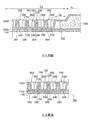
- FIG. 4 is a cross-sectional view taken along line AA and line BB in FIG. 3.
- the molding apparatus which manufactures the resin panels which concern on embodiment it is a side view which shows the state by which the molten resin sheet was arrange
- the molding apparatus which manufactures the resin panels which concern on embodiment it is a schematic side view which shows the state which is making the outer frame of a division mold contact the side surface of a molten resin sheet.
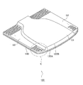
- FIG. 1 is a perspective view of the front side of a resin panel 1 according to the embodiment.
- FIG. 2 is a perspective view of the back side of the resin panel 1 according to the embodiment.
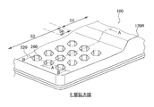
- FIG. 3 is an enlarged view of a portion E in FIG. 4 is a cross-sectional view taken along line AA and line BB in FIG.
- the resin panel 100 includes a front sheet 120A, a back sheet 120B, and a decorative material sheet 140 bonded to the outer surface 150 of the front sheet 120A.
- the resin panel 100 is configured to have a three-layer structure including a decorative material sheet 140, a front side sheet 120A, and a back side sheet 120B. In addition, it is not essential to provide the decorative material sheet 140 in the resin panel 100 of the present embodiment.
- the resin panel 100 of the present embodiment has a comparison in thickness between the outer surface 150 of the front sheet 120 ⁇ / b> A and the outer surface 220 of the back sheet 120 ⁇ / b> B.
- the thin second region S2 is provided around the thick first region S1. The thickness of the first region S1 and the thickness of the second region S2 of the resin panel 100 may be appropriately determined according to the intended use.
- the thickness of the first region S1 is 15 mm or less, preferably 10 mm or less from the viewpoint of lightness, and the front side sheet 120A and the back side sheet
- the thickness of 120B is 1.5 mm or less, preferably 1.0 mm or less.
- a core member 300 is provided between the front side sheet 120A and the back side sheet 120B.
- a large number of recesses 200 are formed in the second region S2 having a relatively small thickness.
- it is adhere
- the depths of the numerous recesses 200 substantially determine the thickness of the second region S2.
- each of the multiple recesses 200 protrudes on the inner surface side by a rib 122 extending between the inner surface 180 of the back surface side sheet 120 ⁇ / b> B and the inner surface 170 of the front surface side sheet 120 ⁇ / b> A. It has a tapered shape toward the inside.
- the butting surface 240 that is the bottom of each recess 200 is adhered to the inner surface 170 of the front surface sheet 120A.
- the number of the plurality of recesses 200 may be set as appropriate according to the application of the resin panel 100, but the higher the number, the higher the rigidity as compared with the weight.
- each of the plurality of recesses 200 is a truncated pyramid in which the opening 260 in the outer surface 220 of the back sheet 120B is a regular hexagon, and the opening 260 as a whole on the outer surface 220 has a honeycomb shape. It is preferable to arrange
- the size of the opening 260 of each of the plurality of recesses 200, the depth of the recesses 200, and the interval between adjacent recesses 200 the size of the opening 260 is small, the depth of the recess 200 is deep, and the interval between adjacent recesses 200 is The smaller the is, the higher the rigidity can be obtained compared to the weight of the resin panel 100 as a whole.
- a sealed hollow portion 280 is formed between the front side sheet 120 ⁇ / b> A and the back side sheet 120 ⁇ / b> B, and the sealed hollow portion 280 is a peripheral end surface of the resin panel 100.
- the outer peripheral wall of the back side sheet 120B is closed.
- the plurality of recesses 200 are preferably distributed evenly on the outer surface 220, but the shapes thereof are various shapes such as a cone shape, a truncated cone shape, a cylindrical shape, a prism shape, a pyramid shape, and a hemispherical shape. May be selected as appropriate.
- the core member 300 extends from the first region S1 in the region Sb near the boundary with the first region S1 in the relatively thin second region S2. Is provided.
- the reason for this configuration is as follows. That is, when a thin region is formed in a part of the resin panel for weight reduction, the rigidity may decrease in the vicinity of the boundary between the thin region and a relatively thick region of the resin panel. .
- rigidity is ensured by the ribs 112 formed along with the numerous recesses 200 in the second region S2 that is a thin region, and between the sheets in the first region S1 that is a thick region.
- the ribs 112 in the region close to the first region S1 in the second region S2, and there is a possibility that the rigidity may be locally reduced. . That is, in the region close to the first region S1 in the second region S2, the distance between the front side sheet 120A and the back side sheet 120B increases, but a rib having a relatively high height is provided in such a region. In the case of providing the rib, it is difficult to provide the rib because the thickness of the rib becomes excessively thin due to the molten resin being stretched during the formation by the mold, and the strength is lowered.
- the thickness changes greatly in the vicinity of the boundary between the second region S2 that is a thin region and the first region S1 that is a relatively thick region. There is a risk that the strength will be reduced due to the thinness in the manufacture of the. Therefore, in the resin panel 100 according to the present embodiment, in the region Sb in the vicinity of the boundary with the first region S1 in the second region S2, the core material 300 extends from the first region S1, thereby providing a thin region. In the vicinity of the boundary between the second region S2 that is the first region S1 and the first region S1 that is a relatively thick region, the local reduction in rigidity is suppressed.
- the back side sheet 120B is formed by clamping two molten parisons positioned between two divided molds and clamping the two divided molds.
- the sealing panel has a sealed hollow portion 280 at a desired position between the front side sheet 120A and the back side sheet 120B and is formed so as to exhibit a desired surface shape.
- the peripheral surfaces of the front side sheet 120A and the back side sheet 120B are welded together to form a parting line PL (described later).
- FIG. 5 is a side view showing a state in which the molten resin sheet is disposed between the divided molds 32A and 32B in the molding apparatus 10 that manufactures the resin panel 100 according to the embodiment.
- FIG. 6 is a schematic side view illustrating a state in which the outer frames of the divided molds 32A and 32B are in contact with the side surfaces of the molten resin sheet in the molding apparatus 10 that manufactures the resin panel 100 according to the embodiment.
- FIG. 7 is a schematic partial cross-sectional view illustrating a state in which a molten resin sheet is shaped in the molding apparatus 10 that manufactures the resin panel 100 according to the embodiment.
- FIG. 5 is a side view showing a state in which the molten resin sheet is disposed between the divided molds 32A and 32B in the molding apparatus 10 that manufactures the resin panel 100 according to the embodiment.
- FIG. 6 is a schematic side view illustrating a state in which the outer frames of the divided molds 32A and 32B are in contact with the side surfaces of the
- FIG. 8 is a diagram illustrating a state in which the core member 300 is pressed against the shaped molten resin sheet.
- FIG. 9 is a diagram showing a state in which the core material is fused to the shaped molten resin sheet.
- FIG. 10 is a diagram illustrating a state in which the split molds 32A and 32B are clamped in the molding apparatus 10 that manufactures the resin panel 100 according to the embodiment.
- FIG. 11 is a diagram illustrating a state where the molds 32A and 32B are opened in the molding apparatus 10 that manufactures the resin panel 100 according to the embodiment.
- the shape is schematically shown for easy understanding. For example, the number of protrusions 119A and recesses 200 is smaller than the actual number.
- the molding apparatus 10 for manufacturing the resin panel 100 includes an extrusion apparatus 12 and a mold clamping apparatus 14 disposed below the extrusion apparatus 12 and is extruded from the extrusion apparatus 12.
- the melted sheet-like parisons P1 and P2 are sent to the mold clamping device 14, and the mold-clamping device 14 forms the melted sheet-like parisons P1 and P2.
- the apparatuses for extruding each of the two thermoplastic resins and sending them to the mold clamping device 14 are the same, only one of them will be described, and the other will be given the same reference number for the description. Omitted.
- the extrusion device 12 is a conventionally known type, and detailed description thereof is omitted, but cylinders 18A and 18B provided with hoppers 16A and 16B, and screws (not shown) provided in the cylinders 18A and 18B, , Hydraulic motors 20A, 20B connected to screws, accumulators 22A, 22B communicating with cylinders 18A, 18B, and plungers 24A, 24B provided in the accumulators 22A, 22B.
- the resin pellets introduced from 16B are melted and kneaded in the cylinders 18A and 18B by the rotation of the screws by the hydraulic motors 20A and 20B, and the molten resin is transferred to the accumulators 22A and 22B to be stored in a certain amount.
- T-die 28A, 28B driven by 24A, 24B The molten resin is fed toward the sheet, and a continuous sheet-like parison P1, P2 having a predetermined length is extruded through the extrusion slits 29A, 29B, and a pair of rollers 30AA, 30AB and a pair of rollers 30BA, While being pinched by 30BB, it is sent out downward and is suspended between the divided molds 32A and 32B.
- the sheet-like parisons P1 and P2 are arranged between the divided molds 32A and 32B in a state where the sheet-like parisons P1 and P2 have a uniform thickness in the vertical direction (extrusion direction).
- the extrusion capability of the extrusion device 12 is appropriately selected from the viewpoints of the size of the resin molded product to be molded, the draw-down of the sheet parisons P1 and P2, and the prevention of neck-in occurrence. More specifically, from a practical point of view, the extrusion rate of one shot in intermittent extrusion is preferably 1 to 10 kg, and the extrusion rate of the resin from the extrusion slits 29A and 29B is several hundred kg / hour or more. Preferably it is 700 kg / hour or more.
- the extrusion process of the sheet-like parisons P1 and P2 is preferably as short as possible, depending on the type of resin, MFR value, and melt tension value. In general, the extrusion process should be completed within 40 seconds, more preferably within 10 to 20 seconds. Therefore, the extrusion amount per unit area and unit time from the extrusion slits 29A and 29B of the thermoplastic resin is 50 kg / hour cm 2 or more, more preferably 150 kg / hour cm 2 or more.
- the sheet-like parisons P1 and P2 sandwiched between the pair of rollers are sent downward by rotation of the pair of rollers 30AA and 30AB and the pair of rollers 30BA and 30BB (hereinafter collectively referred to as “a pair of rollers 30” as appropriate).
- the sheet-like parisons P1 and P2 can be stretched and thinned, and the relationship between the extrusion speed of the extruded sheet-like parisons P1 and P2 and the delivery speed of the sheet-like parisons P1 and P2 by a pair of rollers is adjusted.
- the extrusion slits 29A and 29B provided in the T dies 28A and 28B are arranged vertically downward, and the sheet-like parisons P1 and P2 extruded from the extrusion slits 29A and 29B remain as they are. , 29B, and is sent vertically downward.
- the extrusion slits 29A and 29B can change the thickness of the sheet-like parisons P1 and P2 by making the interval variable.
- the pair of rollers 30AA and 30AB will be described.
- the pair of rollers 30AA and 30AB are arranged below the extrusion slit 29A so that their respective rotation shafts are parallel to each other substantially horizontally, and one of the rollers 30AA is a rotation driving roller.
- the other roller 30AB is a driven roller (or driven roller). More specifically, as shown in FIG. 3, the pair of rollers 30AA and 30AB are arranged so as to be line-symmetric with respect to the sheet-like parison P1 extruded in a form that hangs downward from the extrusion slit 29A.
- each roller and the axial length of the roller may be appropriately set according to the extrusion speed of the sheet parisons P1 and P2 to be formed, the length and width of the sheet in the extrusion direction, the type of resin, and the like.
- the diameter of the rotation driving roller 30AA is set to be driven to rotate. It is preferably slightly larger than the diameter of the roller 30AB.
- each roller is preferably in the range of 50 to 300 mm, and causes the trouble that the sheet-like parison P1 is wound around the roller even when the roller curvature is too large or too small in contact with the sheet-like parison P1. It becomes.
- the mold clamping device 14 is also a conventionally known type like the extrusion device 12, and detailed description thereof is omitted, but the two divided molds 32A and 32B and the molds 32A and 32B are in a molten state.
- a mold driving device (not shown) that moves between an open position and a closed position in a direction substantially perpendicular to the supply direction of the sheet-like parisons P1 and P2.
- the two divided molds 32A and 32B are arranged in a state where the cavities 116A and 116B face each other, and the cavities 116A and 116B are arranged along the substantially vertical direction, respectively.
- the surface of each of the cavities 116A and 116B has a shape corresponding to the outer shape of the molded product molded based on the melted sheet-like parisons P1 and P2. More specifically, in the cavity 116A of one mold 32A for molding the back surface side sheet 120B, there are a front surface 116Aa corresponding to the thin second region S2 of the resin panel 100 and a thick second region S2 of the resin panel 100. And a surface 116Ab corresponding to.
- a protrusion 119A complementary to the recess 200 is formed toward the cavity 116B of the other mold 32B so as to form the recess 200 on the outer surface of the back sheet 120B. It is provided to protrude.
- the plurality of protrusions 119A are arranged on the surface 116Aa of the cavity 116A in a plurality of rows on the surface 116Aa of the cavity 116A at a predetermined interval in the vertical direction. It may form a strip shape extending in the horizontal direction. Thereby, the recessed part 200 is formed as a recessed groove.
- the plurality of protrusions 119A may be arranged in a staggered pattern on the surface 116Aa of the cavity 116A.
- pinch-off portions 118A and 118B are formed around the cavities 116A and 116B.
- the pinch-off portions 118A and 118B are formed in an annular shape around the cavities 116A and 116B, and project toward the opposing molds 32A and 32B.
- the tip portions of the respective pinch-off portions 118A and 118B come into contact with each other so that the two sheet-like parisons P1 and P2 in the molten state are formed on the periphery thereof. It is welded so that the parting line PL is formed, and an outer peripheral wall that closes the hollow portion is formed.
- the molds 33A and 34A are fitted on the outer periphery of the mold 32A so as to be slidable in a sealed state, and the molds 33A and 34A are relatively moved relative to the mold 32A by a mold moving device (not shown). It can be moved. More specifically, the molds 33A and 34A can be brought into contact with the side surface of the sheet-like parison P1 disposed between the molds 32A and 32B by projecting toward the mold 32B with respect to the mold 32A. is there.
- the mold driving device is the same as the conventional one, and the description thereof is omitted.
- the two divided molds 32A and 32B are each driven by the mold driving device, and in the open position, the two divided molds are used.
- Two sheet-like parisons P1 and P2 can be arranged between 32A and 32B, and the pinch-off portions 118A and 118B of the two divided molds 32A and 32B abut at one closed position, The annular pinch-off portions 118A and 118B are in contact with each other, so that a sealed space is formed in the two divided molds 32A and 32B.
- the closed position that is, the position where the pinch-off portions 118A and 118B abut each other is between the two melted sheet-like parisons P1 and P2.
- the split molds 32A and 32B are driven by a mold driving device so as to move toward the positions at equal positions from both sheet-like parisons P1 and P2.
- the extrusion device and the pair of rollers for one sheet-like parison P1 and the extrusion device and the pair of rollers for the other sheet-like parison P2 are arranged symmetrically with respect to this closed position.
- a vacuum suction chamber 80 is provided inside the divided mold 32 ⁇ / b> A, and the vacuum suction chamber 80 communicates with the cavity 116 ⁇ / b> A through the suction hole 82, and the suction hole 82 is opened from the vacuum suction chamber 80.
- the sheet-like parison P1 is adsorbed toward the cavity 116A by being sucked through, and shaped into a shape along the outer surface of the cavity 116A. That is, the back surface side sheet 120B of the resin panel 100 is formed by the front surfaces 116Aa and 116Ab of the cavity 116A.
- a conventionally known blow pin (not shown) is applied to the divided molds 32A and 32B so that when the divided molds 32A and 32B are clamped, a blowing pressure can be applied from within a sealed space formed by both molds. Is installed.
- the sheet-like parisons P1 and P2 that are materials of the front side sheet 120A and the back side sheet 120B are made of an olefin resin such as polyethylene or polypropylene, or a sheet formed from an amorphous resin or the like. More specifically, the sheet-like parisons P1 and P2 are preferably made of a resin material having a high melt tension from the viewpoint of preventing a variation in thickness due to drawdown, neck-in, etc. It is preferable to use a resin material with high fluidity in order to improve the transferability and followability.
- polyolefin for example, polypropylene, high density polyethylene
- polypropylene high density polyethylene
- MFR JIS
- K-7210 measured at a test temperature of 230 ° C.
- a test load of 2.16 kg of 3.0 g / 10 min or less, more preferably 0.3 to 1.5 g / 10 min, or acrylonitrile butadiene Amorphous resin such as styrene copolymer, polystyrene, high impact polystyrene (HIPS resin), acrylonitrile / styrene copolymer (AS resin), MFR at 200 ° C. (test temperature 200 according to JIS K-7210) Measured at 2.degree. C. and a test load of 2.16 kg) is 3.0 to 60 g / 10 Min, more preferably 30-50 g / 10 min, and a melt tension at 230 ° C.
- HIPS resin high impact polystyrene
- AS resin acrylonitrile / styrene copolymer
- MFR at 200 ° C. (test temperature 200 according to JIS K-7210) Measured at 2.degree. C. and a test load of 2.16 kg) is 3.0 to
- the strand is extruded from an orifice having a length of 8 mm and the tension when the strand is wound around a roller having a diameter of 50 mm at a winding speed of 100 rpm) is 50 mN or more, preferably 120 mN or more.
- a hydrogenated styrene-based thermoplastic elastomer is added in an amount of less than 30 wt%, preferably less than 15 wt%.
- styrene-ethylene / butylene-styrene block copolymers, styrene-ethylene / propylene-styrene block copolymers, hydrogenated styrene-butadiene rubbers and mixtures thereof are suitable as hydrogenated styrene thermoplastic elastomers.
- the styrene content is less than 30 wt%, preferably less than 20 wt%, and the MFR at 230 ° C. (measured at a test temperature of 230 ° C. and a test load of 2.16 kg according to JIS K-7210) is 1.0 to 10 g / 10 Minute, preferably 5.0 g / 10 min or less and 1.0 g / 10 min or more.
- the sheet-like parisons P1 and P2 may contain an additive.
- the additive include inorganic fillers such as silica, mica, talc, calcium carbonate, glass fiber, and carbon fiber, plasticizer, and stability. Agents, colorants, antistatic agents, flame retardants, foaming agents and the like. Specifically, silica, mica, glass fiber or the like is added in an amount of 50 wt% or less, preferably 30 to 40 wt% with respect to the molding resin.
- the decorative material sheet 140 is an object that improves appearance, decoration, and contacts with the molded product (for example, In the case of a cargo floor board, the cargo floor board is configured for the purpose of protecting a load placed on the upper surface of the board.
- the material of the decorative material sheet 140 is a fiber skin material, a sheet-like skin material, a film-like skin material, or the like.
- synthetic fibers such as polyester, polypropylene, polyamide, polyurethane, acrylic and vinylon, semi-synthetic fibers such as acetate and rayon, regenerated fibers such as viscose rayon and copper ammonia rayon, cotton, hemp, Examples thereof include natural fibers such as wool and silk, or blended fibers thereof.
- polyester is preferable and polyester is more preferable from the viewpoints of touch, durability, and moldability.
- the yarn used for the fiber skin material is, for example, polyester: (3-5) denier x (50-100) mm, etc., a fineness of 3-15 denier, and a staple spun yarn having a fiber length of about 2-5 inches
- Polyester with bundles of thin flexible filaments: about 150 to 1000 denier / 30 to 200 filaments about 5 denier ⁇ 30 to 200 multifilaments, or polyester: 400 to 800 denier per filament -It is preferable to use in combination with a filament.
- Examples of the structure of the decorative material sheet 140 include non-woven fabrics, woven fabrics, knitted fabrics, and fabrics obtained by raising them.
- the woven fabric includes not only a plain structure in which the woven structure is tangled up and down in order, but also various changed woven forms in which some yarns are entangled and jumped.
- a non-woven fabric is preferable because it can be easily formed into a three-dimensional shape and has excellent surface feel and texture.
- the non-woven fabric means a cloth-like product in which fibers are stacked in parallel or alternately or are randomly dispersed to form a web, and then the fibers that become the web are joined.
- the nonwoven fabric obtained by the needle punch method has lower strength and higher elongation than the woven fabric and has a large degree of deformation in any direction, it improves the strength of the nonwoven fabric and stabilizes its dimensions. For this reason, it is more preferable to attach a binder to the woven fabric or to punch the web and the nonwoven fabric with overlapping needles. From these things, it is more preferable that the decorative material sheet 140 is a polypropylene nonwoven fabric or a polyester nonwoven fabric.
- the decorative material sheet 140 itself is thermoplastic, it can be used for another purpose by being heated and deformed after separation and collection.
- the main resin layer is made of polypropylene and the decorative material sheet 140 is made of a polypropylene nonwoven fabric, the main resin layer and the decorative material sheet 140 of the molded product are the same material, which facilitates recycling.
- the decorative material sheet 140 is a polyester non-woven fabric
- the melting point of the main resin layer made of polypropylene and the fiber skin material are different, so that when the decorative material sheet 140 is bonded to a molded product, it is altered by heat and deformed.
- the tensile strength of the decorative material sheet 140 is 15 kg / cm from the viewpoint of three-dimensional shape reproducibility and moldability. It is preferably 2 or more, and the elongation is preferably 30% or more.
- thermoplastic elastomer embossed resin layer, resin layer with printed layer attached to the outer surface, synthetic leather, non-slip mesh-shaped skin layer, etc.
- resin layer with printed layer attached to the outer surface synthetic leather, non-slip mesh-shaped skin layer, etc.
- thermoplastic resin is stored in the accumulators 22A and 22B, and the stored thermoplastic resin is removed from the extrusion slits 29A and 29B provided in the T dies 28A and 28B.
- the thermoplastic resin swells and is extruded at a predetermined extrusion speed with a predetermined thickness so as to hang downward into a molten sheet.
- the pair of rollers 30 was moved to the open position, and the gap between the pair of rollers 30 arranged below the extrusion slits 29A and 29B was expanded below the thickness of the sheet-like parisons P1 and P2, thereby being pushed out downward.
- the lowermost portions of the melted sheet-like parisons P 1 and P 2 are smoothly supplied between the pair of rollers 30.
- the timing at which the interval between the rollers 30 is increased beyond the thickness of the sheet-like parisons P1 and P2 may be performed after the end of the secondary molding for each one shot, not after the start of extrusion.
- the pair of rollers 30 are moved close to each other and moved to the closed position, the sheet-like parisons P1 and P2 are sandwiched by narrowing the interval between the pair of rollers 30, and the sheet-like parisons P1 and P2 are moved downward by the rotation of the rollers. Send it out.
- the sheet-like parisons P ⁇ b> 1 and P ⁇ b> 2 having a uniform thickness in the extrusion direction are disposed between the divided molds 32 ⁇ / b> A and 32 ⁇ / b> B disposed below the pair of rollers 30.
- the sheet-like parisons P1 and P2 are positioned in a form that protrudes around the pinch-off portions 118A and 118B.
- the above steps are performed for each of the two sheet-like parisons P1 and P2, and the sheet-like parison P2 that is the material of the front side sheet 120A and the sheet-like parison P1 that is the material of the back side sheet 120B are mutually connected. It arrange
- the sheet-like parison P1 that is the material of the back-side sheet 120B is stretched along the protrusions of the mold cavity during molding because the plurality of recesses 200 are formed, and the recesses 200 are not provided.
- the surface side sheet 120A tends to be thinner than the sheet-like parison P2 that is the material of the front side sheet 120A.
- the back side sheet 120B can be obtained by clamping the divided molds 32A and 32B.
- the interval between the extrusion slits 29A may be wider than the interval between the extrusion slits 29B. Accordingly, it is possible to make thicker.
- the molds 33A and 34A are placed on the outside of the sheet-like parison P1 facing the mold 32A toward the sheet-like parison P1 that is the material of the back-side sheet 120B with respect to the mold 32A. Move until it hits the surface 117.
- the decorative material sheet 140 may be appropriately suspended above the mold and suspended in advance along the cavity surface. The timing of disposing the decorative material sheet 140 may be performed before the molds 32A and 32B are clamped.
- the vacuum is passed through the sealed space 84 formed by the cavity 116A of the mold 32A, the molds 33A and 34A, and the outer surface 117 of the sheet-like parison P1 facing the mold 32A.
- the suction chamber 80 By sucking from the suction chamber 80 through the suction hole 82, the sheet-like parison P1 is pressed against the cavity 116A, and the sheet-like parison P1 is shaped into a shape along the surface of the cavity 116A. Thereby, the back surface side sheet 120B is formed.
- the core member 300 held by the manipulator 400 is moved in the direction of the arrow in the figure, and pressed against the sheet-like parison P1 formed along the surface of the cavity 116A.
- the core member 300 is welded to the sheet-like parison P1 as shown in FIG.
- the manipulator 400 accurately performs positioning along the vertical direction (that is, the extrusion direction of the sheet-like parison P1) when the core member 300 is welded to the sheet-like parison P1. That is, as shown in FIG.
- the core material with respect to the surface 116Ab of the cavity 116A is positioned so that both ends of the core material 300 are located in the region Sb in the vicinity of the boundary between the first region S1 and the second region S2 in the back sheet 120B.
- the manipulator 400 holding 300 is positioned and controlled by an actuator (not shown), and then the core member 300 is pressed against the sheet-like parison P1.
- each annular pinch-off portion is held while sucking and holding the sheet-like parison P1 in a state where the molds 33A and 34A that are in contact with the outer surface 117 of the sheet-like parison P1 are held in their positions.
- Both split molds 32A and 32B are moved in a direction approaching each other until 118A and 118B come into contact with each other.
- the contact position in the mold clamping direction between the pinch-off portions 118A and 118B is between the two sheet-like parisons P1 and P2 that are separated from each other.
- the pinch-off portions 118A , 118B come into contact with each other, the peripheral edges of the two sheet-like parisons P1 and P2 are welded and fixed, and the abutting surfaces 240 of many concave portions 200 formed on the surface of the back surface side sheet 120B. It is welded to the inner surface of the front side sheet 120A. Thereby, the sealed hollow portion 280 is formed between the back surface side sheet 120B and the front surface side sheet 120A.
- the split molds 32A and 32B are opened, the molded resin panel 100 is taken out, and the burr portions B outside the pinch-off portions 118A and 118B are cut, thereby completing the molding.
- thermoplastic resin is intermittently extruded as melted sheet-like parisons P1 and P2 by extrusion molding, and the sheet-like parisons P1 and P2 extruded by vacuum forming or pressure forming are shaped into a predetermined shape using a mold. Is possible.
- the manufacturing method of the resin panel 100 having the above configuration when it is difficult to adjust the thickness of the cylindrical parison in the circumferential direction as in the conventional technique, for example, blow molding using the cylindrical parison.
- the blowing pressure is applied in the parison after the mold is clamped, the problem that the thickness of the sheet after molding is locally thinned according to the blow ratio can be solved. It is. That is, after positioning two thermoplastic resin sheets whose thicknesses are adjusted independently between the split molds 32A and 32B, one resin sheet and the cavity 116A of the mold facing the resin sheet are arranged.
- thermoplastic resin sheet 116B is formed with a sealed space, and the inside of the sealed space is sucked from the mold side, so that the required strength and molding can be obtained depending on the degree to which the thermoplastic resin sheet is stretched along the respective cavity shapes. It is possible to reduce the thickness of each of the two resin sheets individually to the maximum as long as they can secure the properties, thereby making it possible to reduce the weight and thickness sufficiently while ensuring manufacturing efficiency and product quality. Achievable.
- the embodiment of the resin panel according to the present invention has been described in detail above, but various modifications or changes can be made by those skilled in the art without departing from the scope of the present invention.
- the present invention is not limited to this.
- the blowing pressure may be applied after the mold clamping of the split mold.
- the extruded sheet-like parison has been described as being directly shaped and molded as the resin panel 100, but the present invention is not limited thereto.
- shaping and molding may be performed using a material that has been once extruded and then heated again to a molten thermoplastic resin sheet.
- the front side sheet 120A when the front side sheet 120A is disposed between the pair of molds, the front side sheet 120A is described as being held above the molds and suspended along the cavity surface. Instead, the mold may be clamped in a state where the decorative material sheet 140 is placed in the cavity 116B by, for example, sucking the decorative material sheet 140 from the mold 32B, or the decorative material sheet 140 is placed on the front side sheet 120A. It is good also as what is arrange
- the second region S2 of the resin panel 100 a case where a rib 122 extending between the inner surface 180 of the back side sheet 120B and the inner surface 170 of the front side sheet 120A is provided will be described. However, this is only an example. In the second region S ⁇ b> 2 of the resin panel 100, a large number of recesses 200 and the ribs 112 formed along with the recesses 200 may not be provided. In that case, required rigidity can also be ensured by increasing the thickness of the back surface side sheet 120B in the thin second region S2. In the resin panel 100 according to the present embodiment, the case where the thin second region S2 is provided around the thick first region S1 has been described, but this is only an example. The first region S1 and the second region S2 can be set at arbitrary positions according to the layout of the resin panel and the intended use.
Landscapes
- Vehicle Step Arrangements And Article Storage (AREA)
- Laminated Bodies (AREA)
- Blow-Moulding Or Thermoforming Of Plastics Or The Like (AREA)
Abstract
本発明の一実施形態は、樹脂製のおもて面側シート(120A)および裏面側シート(120B)によって芯材(300)を挟む積層構造の樹脂製パネル(1)であり、おもて面側シートの外表面(150)と裏面側シートの外表面(220)の間の厚さが比較的厚い領域であって、シート間に芯材が設けられている第1領域(S1)と、上記厚さが第1領域(S1)よりも薄い第2領域(S2)と、を含む。そして、第2領域(S2)のうち第1領域(S1)との境界近傍の領域において、芯材(300)が第1領域(S1)から延在して設けられている。
Description
本発明は、樹脂製パネルに関する。
従来から、樹脂製パネルが、自動車、航空機等の輸送機械用、建材用、電気機器のハウジング用、スポーツ・レジャー用等多用途に用いられてきた。樹脂製パネルは、芯材を表皮材シートで覆うものであるが、芯材の一方の面のみを表皮材シートで覆うものと、芯材の両方の面を表皮材シートで覆うものが存在する。芯材の一方の面のみを表皮材シートで覆う樹脂製パネルは、例えば建材用等、使用者に視認されないために芯材の他方の面を表皮材シートで覆う必要がない用途などに用いられる。芯材の両方の面を表皮材シートで覆う樹脂製パネルは、サンドイッチパネルとも呼称される。樹脂製パネルは、2枚の表皮材シート、両表皮材シートとの間に介在する芯材とを有する。すなわち、樹脂製パネルは、表皮材シート、芯材および表皮材シートの積層構造が基本的形態である。
従来、芯材となる樹脂発泡体に金属製の補強材をインサートしたものが知られている。例えば特開2010-174577号公報には、中空二重壁構造の中空部に、中空部内の空間と略同一形状に予め成形された熱可塑性樹脂からなる芯材に補強材を嵌合して芯材と補強材が一体となった内装材を内装することにより、内装する内装材の位置決めが的確にできて、ガタツキ防止や成形収縮による変形を起こすことがないようにした樹脂製パネルが開示されている。
従来の樹脂製パネルは、剛性を高くする要求が低い部位には軽量化のために薄型化をし、剛性を高くする要求が高い部位には、板厚を大きくとって芯材を挟み込むように構成していた。しかし、薄い部位と厚い部位との境界付近において芯材が設けられていない部分が存在し、当該部分の剛性が低いために力を掛けたときに撓み量が大きく、あるいは異音がする等して品質上好ましくない場合があった。薄い部位にリブを設けることで薄い部位でも剛性を高くすることも行われてきたが、境界部分にリブを設けたとすれば、比較的背の高いリブを設定せざるを得ないが、その場合には、成形時にリブの肉厚が低下してしまう等、製造品質が低下することがある。そのため、境界部分にリブを設けることは困難である。
本開示の目的は、比較的薄い領域と比較的厚い領域とが設けられている場合に、薄い領域と厚い領域との境界近傍の領域の剛性低下を効果的に抑制するようにした樹脂製パネルを提供することである。
本開示の第1の観点は、樹脂製のおもて面側シートおよび裏面側シートによって芯材を挟む積層構造の樹脂製パネルである。この樹脂製パネルは、おもて面側シートの外表面と裏面側シートの外表面の間の厚さが比較的厚い領域であって、シート間に芯材が設けられている第1領域と、前記厚さが第1領域よりも薄い第2領域と、を含み、第2領域のうち第1領域との境界近傍の領域において、芯材が第1領域から延在して設けられていることを特徴とする。
前記樹脂製パネルにおいて、前記第2領域では、裏面側シートの内表面とおもて面側シートの内表面との間を延びるリブが設けられていてもよい。
前記樹脂製パネルにおいて、前記第2領域が前記第1領域の周囲に設けられていてもよい。
本開示に係る樹脂製パネルによれば、比較的薄い領域と比較的厚い領域とが設けられている場合に、薄い領域と厚い領域との境界近傍の領域の剛性低下を効果的に抑制することができる。
本発明の一実施形態に係る樹脂製パネル100について、図1~4を参照しながら、以下に詳細に説明する。図1は、実施形態に係る樹脂製パネル1のおもて面側の斜視図である。図2は、実施形態に係る樹脂製パネル1の裏面側の斜視図である。図3は、図2のE部の拡大図である。図4は、図3の線A-Aおよび線B-Bに沿う断面図である。
図1~3に示すように、樹脂製パネル100は、おもて面側シート120Aと裏面側シート120Bと、おもて面側シート120Aの外表面150に貼り合わされた化粧材シート140とから構成され、樹脂製パネル100は、化粧材シート140、おもて面側シート120A、および裏面側シート120Bの3層からなる積層構造である。
なお、本実施形態の樹脂製パネル100において、化粧材シート140を設けることは必須ではない。
図1~3に示すように、樹脂製パネル100は、おもて面側シート120Aと裏面側シート120Bと、おもて面側シート120Aの外表面150に貼り合わされた化粧材シート140とから構成され、樹脂製パネル100は、化粧材シート140、おもて面側シート120A、および裏面側シート120Bの3層からなる積層構造である。
なお、本実施形態の樹脂製パネル100において、化粧材シート140を設けることは必須ではない。
図2および図3に明瞭に見られるように、本実施形態の樹脂製パネル100は、おもて面側シート120Aの外表面150と裏面側シート120Bの外表面220の間の厚さが比較的厚い第1領域S1と、当該厚さが第1領域S1よりも薄い第2領域S2とを含む。本実施形態の樹脂製パネル100では、薄い第2領域S2が厚い第1領域S1の周囲に設けられている。
樹脂製パネル100の第1領域S1の厚さ、および、第2領域S2の厚さは、使用用途に応じて適宜定めればよい。樹脂製パネル100を例えば車両用のトランクボードとして使用する場合、軽量性の観点から第1領域S1の厚さが15mm以下、好ましくは10mm以下であり、おもて面側シート120Aと裏面側シート120Bの肉厚が1.5mm以下、好ましくは1.0mm以下である。
樹脂製パネル100の第1領域S1の厚さ、および、第2領域S2の厚さは、使用用途に応じて適宜定めればよい。樹脂製パネル100を例えば車両用のトランクボードとして使用する場合、軽量性の観点から第1領域S1の厚さが15mm以下、好ましくは10mm以下であり、おもて面側シート120Aと裏面側シート120Bの肉厚が1.5mm以下、好ましくは1.0mm以下である。
図3および図4に示すように、樹脂製パネル100の第1領域S1には、おもて面側シート120Aと裏面側シート120Bのシート間に芯材300が設けられている。
樹脂製パネル100において比較的厚みが薄い第2領域S2には、多数の凹部200が形成されている。多数の凹部200の各底部では、おもて面側シート120Aの化粧材シート140が接着される外表面150と反対側の面である内表面170に接着されている。多数の凹部200の深さが第2領域S2の厚さを実質的に決定している。
樹脂製パネル100において比較的厚みが薄い第2領域S2には、多数の凹部200が形成されている。多数の凹部200の各底部では、おもて面側シート120Aの化粧材シート140が接着される外表面150と反対側の面である内表面170に接着されている。多数の凹部200の深さが第2領域S2の厚さを実質的に決定している。
図3および図4に示すように、多数の凹部200それぞれは、裏面側シート120Bの内表面180とおもて面側シート120Aの内表面170との間を延びるリブ122により、内表面側で突出するように内方に向かって先細り形状となっている。裏面側シート120Bの内表面180のうち各凹部200の底部となる突き合わせ面240がおもて面側シート120Aの内表面170に接着されるようにしている。
複数の凹部200の数は、樹脂製パネル100の用途に応じて適宜設定すればよいが、数が多いほど重量に比して高い剛性を得ることができる。
複数の凹部200の数は、樹脂製パネル100の用途に応じて適宜設定すればよいが、数が多いほど重量に比して高い剛性を得ることができる。
図3および図4に示すように、複数の凹部200はそれぞれ、裏面側シート120Bの外表面220における開口260が正六角形となる角錐台であり、外表面220上で開口260が全体としてハニカム状に配置されていることが好ましい。すなわち、外表面220上で、隣り合う開口260の対向する辺同士が平行となるように配置されている。これにより、外表面220において最も密に複数の凹部200を配置することが可能となる。
また、それとは別に、裏面側シート120Bの外表面220上において、隣り合う正六角形の角錐台形状の開口260の角同士が近接するように配置することも可能である。開口260の角同士が近接するように均等に配置することで、このような金型を製作するうえで切削加工が容易となる。複数の凹部200それぞれの開口260の大きさ、凹部200の深さおよび隣り合う凹部200同士の間隔について、開口260の大きさが小さく、凹部200の深さが深く、隣り合う凹部200同士の間隔が小さいほど、樹脂製パネル100全体としての重量に比して高い剛性を得ることができる。
また、それとは別に、裏面側シート120Bの外表面220上において、隣り合う正六角形の角錐台形状の開口260の角同士が近接するように配置することも可能である。開口260の角同士が近接するように均等に配置することで、このような金型を製作するうえで切削加工が容易となる。複数の凹部200それぞれの開口260の大きさ、凹部200の深さおよび隣り合う凹部200同士の間隔について、開口260の大きさが小さく、凹部200の深さが深く、隣り合う凹部200同士の間隔が小さいほど、樹脂製パネル100全体としての重量に比して高い剛性を得ることができる。
図3および図4に示すように、おもて面側シート120Aと裏面側シート120Bとの間には、密閉中空部280が形成されており、密閉中空部280が樹脂製パネル100の周端面において、裏面側シート120Bの外周壁により閉じられている。
変形例として、複数の凹部200は、外表面220において均等に分散配置させるのが好ましいが、その形状は、円錐形状、円錐台形状、円筒形状、角柱形状、角錐形状、半球形状など多種の形状から適宜選択すればよい。
変形例として、複数の凹部200は、外表面220において均等に分散配置させるのが好ましいが、その形状は、円錐形状、円錐台形状、円筒形状、角柱形状、角錐形状、半球形状など多種の形状から適宜選択すればよい。
図4に示すように、本実施形態の樹脂製パネル100では、比較的薄い第2領域S2のうち第1領域S1との境界近傍の領域Sbにおいて、芯材300が第1領域S1から延在して設けられている。このように構成しているのは以下の理由からである。
すなわち、軽量化のために樹脂製パネルの一部に薄い領域を形成した場合、その薄い領域と、樹脂製パネルのうち比較的厚い領域との間の境界近傍では、剛性が低下する場合がある。本実施形態の樹脂製パネル100では、薄い領域である第2領域S2では多数の凹部200に伴って形成されるリブ112によって剛性を確保しており、厚い領域である第1領域S1ではシート間に芯材300を設けることで剛性を確保しているが、第2領域S2のうち第1領域S1に近い領域ではリブ112を設けることが製造上難しく、剛性が局所的に低下する虞がある。つまり、第2領域S2のうち第1領域S1に近い領域では、おもて面側シート120Aと裏面側シート120Bの距離が拡がっていくが、そのような領域に比較的高さのあるリブを設けようとした場合、金型による形成時に溶融樹脂が引き伸ばされることでリブの肉厚が薄くなり過ぎ、強度が低下するため、リブを設けることが難しい。また、リブを設けない場合であっても、薄い領域である第2領域S2と比較的厚い領域である第1領域S1との境界近傍では厚みが大きく変化するため、その境界近傍では金型での製造上やはり薄肉となって強度が低下する虞がある。
そこで、本実施形態の樹脂製パネル100では、第2領域S2のうち第1領域S1との境界近傍の領域Sbにおいて、芯材300を第1領域S1から延在して設けることで、薄い領域である第2領域S2と比較的厚い領域である第1領域S1との境界近傍において局所的に剛性が低下することを抑制するようにしている。
すなわち、軽量化のために樹脂製パネルの一部に薄い領域を形成した場合、その薄い領域と、樹脂製パネルのうち比較的厚い領域との間の境界近傍では、剛性が低下する場合がある。本実施形態の樹脂製パネル100では、薄い領域である第2領域S2では多数の凹部200に伴って形成されるリブ112によって剛性を確保しており、厚い領域である第1領域S1ではシート間に芯材300を設けることで剛性を確保しているが、第2領域S2のうち第1領域S1に近い領域ではリブ112を設けることが製造上難しく、剛性が局所的に低下する虞がある。つまり、第2領域S2のうち第1領域S1に近い領域では、おもて面側シート120Aと裏面側シート120Bの距離が拡がっていくが、そのような領域に比較的高さのあるリブを設けようとした場合、金型による形成時に溶融樹脂が引き伸ばされることでリブの肉厚が薄くなり過ぎ、強度が低下するため、リブを設けることが難しい。また、リブを設けない場合であっても、薄い領域である第2領域S2と比較的厚い領域である第1領域S1との境界近傍では厚みが大きく変化するため、その境界近傍では金型での製造上やはり薄肉となって強度が低下する虞がある。
そこで、本実施形態の樹脂製パネル100では、第2領域S2のうち第1領域S1との境界近傍の領域Sbにおいて、芯材300を第1領域S1から延在して設けることで、薄い領域である第2領域S2と比較的厚い領域である第1領域S1との境界近傍において局所的に剛性が低下することを抑制するようにしている。
裏面側シート120Bが、後に説明するように、2つの分割形式の金型の間に位置決めした溶融状態の2枚のシート状パリソンを当該2つの分割形式の金型を型締することにより成形される場合、樹脂製パネル100の用途に応じて、おもて面側シート120Aと裏面側シート120Bとの間の所望の位置に密閉中空部280を有するとともに所望の表面形状を呈するように形成する一方、おもて面側シート120Aと裏面側シート120Bとを溶着し、樹脂製パネル100の用途に応じた外形あるいは表面形状および内部構造を所望に実現可能な樹脂製パネル100を提供することが可能である。特に、おもて面側シート120Aおよび裏面側シート120B同士の周縁面が互いに溶着することにより、パーティングラインPL(後述する)が形成される。
次に、このような樹脂製パネル100を製造するための成形装置について、図5~11を参照して以下に説明する。
図5は、実施形態に係る樹脂製パネル100を製造する成形装置10において、溶融樹脂シートが分割金型32A,32Bの間に配置された状態を示す側面図である。図6は、実施形態に係る樹脂製パネル100を製造する成形装置10において、分割金型32A,32Bの外枠を溶融樹脂シートの側面に当接させている状態を示す概略側面図である。図7は、実施形態に係る樹脂製パネル100を製造する成形装置10において、溶融樹脂シートを賦形している状況を示す概略部分断面図である。図8は、芯材300を賦形された溶融樹脂シートに押し当てる状態を示す図である。図9は、賦形された溶融樹脂シートに芯材が融着した状態を示す図である。図10は、実施形態に係る樹脂製パネル100を製造する成形装置10において、分割金型32A,32Bを型締めした状態を示す図である。図11は、実施形態に係る樹脂製パネル100を製造する成形装置10において、分割金型32A,32Bを型開きした状態を示す図である。
なお、図5~11の各図では、理解の容易のために形状を概略的に記載してある。例えば、突起体119Aや凹部200の数は、実際のものよりも少なく記載してある。
図5は、実施形態に係る樹脂製パネル100を製造する成形装置10において、溶融樹脂シートが分割金型32A,32Bの間に配置された状態を示す側面図である。図6は、実施形態に係る樹脂製パネル100を製造する成形装置10において、分割金型32A,32Bの外枠を溶融樹脂シートの側面に当接させている状態を示す概略側面図である。図7は、実施形態に係る樹脂製パネル100を製造する成形装置10において、溶融樹脂シートを賦形している状況を示す概略部分断面図である。図8は、芯材300を賦形された溶融樹脂シートに押し当てる状態を示す図である。図9は、賦形された溶融樹脂シートに芯材が融着した状態を示す図である。図10は、実施形態に係る樹脂製パネル100を製造する成形装置10において、分割金型32A,32Bを型締めした状態を示す図である。図11は、実施形態に係る樹脂製パネル100を製造する成形装置10において、分割金型32A,32Bを型開きした状態を示す図である。
なお、図5~11の各図では、理解の容易のために形状を概略的に記載してある。例えば、突起体119Aや凹部200の数は、実際のものよりも少なく記載してある。
図5に示すように、樹脂製パネル100を製造するための成形装置10は、押出装置12と、押出装置12の下方に配置された型締装置14とを有し、押出装置12から押出された溶融状態のシート状パリソンP1,P2を型締装置14に送り、型締装置14により溶融状態のシート状パリソンP1,P2を成形するようにしている。ここに、2枚の熱可塑性樹脂それぞれを押し出して、型締装置14まで送るまでの装置は、同様であるので、一方のみ説明し、他方については同様な参照番号を付することによりその説明は省略する。
押出装置12は、従来既知のタイプであり、その詳しい説明は省略するが、ホッパー16A,16Bが付設されたシリンダ18A,18Bと、シリンダ18A,18B内に設けられたスクリュー(図示せず)と、スクリューに連結された油圧モータ20A,20Bと、シリンダ18A,18Bと内部が連通したアキュムレータ22A,22Bと、アキュムレータ22A,22B内に設けられたプランジャー24A,24Bとを有し、ホッパー16A,16Bから投入された樹脂ペレットが、シリンダ18A,18B内で油圧モータ20A,20Bによるスクリューの回転により溶融、混練され、溶融状態の樹脂がアキュムレータ22A,22Bに移送されて一定量貯留され、プランジャー24A,24Bの駆動によりTダイ28A,28Bに向けて溶融樹脂を送り、押出スリット29A,29Bを通じて所定の長さの連続的なシート状パリソンP1,P2が押し出され、間隔を隔てて配置された一対のローラ30AA,30ABおよび一対のローラ30BA,30BBによって挟圧されながら下方へ向かって送り出されて分割金型32A,32Bの間に垂下される。これにより、後に詳細に説明するように、シート状パリソンP1,P2が上下方向(押出方向)に一様な厚みを有する状態で、分割金型32A,32Bの間に配置される。
押出装置12の押出の能力は、成形する樹脂成形品の大きさ、シート状パリソンP1,P2のドローダウンあるいはネックイン発生防止の観点から適宜選択する。より具体的には、実用的な観点から、間欠押出における1ショットの押出量は好ましくは1~10kgであり、押出スリット29A,29Bからの樹脂の押出速度は、数百kg/時以上、より好ましくは700kg/時以上である。また、シート状パリソンP1,P2のドローダウンあるいはネックイン発生防止の観点から、シート状パリソンP1,P2の押出工程はなるべく短いのが好ましく、樹脂の種類、MFR値、メルトテンション値に依存するが、一般的に、押出工程は40秒以内、より好ましくは10~20秒以内に完了するのがよい。このため、熱可塑性樹脂の押出スリット29A,29Bからの単位面積、単位時間当たりの押出量は、50kg/時cm2以上、より好ましくは150kg/時cm2以上である。
一対のローラ30AA,30ABおよび一対のローラ30BA,30BB(以下、適宜「一対のローラ30」と総称する。)の回転により一対のローラ間に挟み込まれたシート状パリソンP1,P2を下方に送り出すことで、シート状パリソンP1,P2を延伸薄肉化することが可能であり、押し出されるシート状パリソンP1,P2の押出速度と一対のローラによるシート状パリソンP1,P2の送り出し速度との関係を調整することにより、ドローダウンあるいはネックインの発生を防止することが可能であるから、樹脂の種類、特にMFR値およびメルトテンション値、あるいは単位時間当たりの押出量に対する制約を小さくすることが可能である。
図5に示すように、Tダイ28A,28Bにそれぞれ設けられる押出スリット29A,29Bは、鉛直下向きに配置され、押出スリット29A,29Bから押し出されたシート状パリソンP1,P2は、そのまま押出スリット29A,29Bから垂下する形態で、鉛直下向きに送られるようにしている。押出スリット29A,29Bは、その間隔を可変とすることにより、シート状パリソンP1,P2の厚みを変更することが可能である。
一対のローラ30AA,30ABについて説明すれば、一対のローラ30AA,30ABは、押出スリット29Aの下方において、各々の回転軸が互いに平行にほぼ水平に配置され、一方のローラ30AAが回転駆動ローラであり、他方のローラ30ABが被回転駆動ローラ(あるいは従動ローラ)である。より詳細には、図3に示すように、一対のローラ30AA,30ABは、押出スリット29Aから下方に垂下する形態で押し出されるシート状パリソンP1に関して、線対称となるように配置される。
それぞれのローラの直径およびローラの軸方向長さは、成形すべきシート状パリソンP1,P2の押出速度、シートの押出方向長さおよび幅、ならびに樹脂の種類等に応じて適宜設定すればよいが、後に説明するように、一対のローラ間にシート状パリソンP1を挟み込んだ状態で、ローラの回転によりシート状パリソンP1を円滑に下方に送り出す観点から、回転駆動ローラ30AAの径は、被回転駆動ローラ30ABの径より若干大きいのが好ましい。各ローラの径は50~300mmの範囲であることが好ましく、シート状パリソンP1との接触においてローラの曲率が大きすぎてもまた、小さすぎてもシート状パリソンP1がローラへ巻き付く不具合の原因となる。
なお、一対のローラ30BA,30BBについても同様である。
それぞれのローラの直径およびローラの軸方向長さは、成形すべきシート状パリソンP1,P2の押出速度、シートの押出方向長さおよび幅、ならびに樹脂の種類等に応じて適宜設定すればよいが、後に説明するように、一対のローラ間にシート状パリソンP1を挟み込んだ状態で、ローラの回転によりシート状パリソンP1を円滑に下方に送り出す観点から、回転駆動ローラ30AAの径は、被回転駆動ローラ30ABの径より若干大きいのが好ましい。各ローラの径は50~300mmの範囲であることが好ましく、シート状パリソンP1との接触においてローラの曲率が大きすぎてもまた、小さすぎてもシート状パリソンP1がローラへ巻き付く不具合の原因となる。
なお、一対のローラ30BA,30BBについても同様である。
一方、型締装置14も、押出装置12と同様に、従来既知のタイプであり、その詳しい説明は省略するが、2つの分割形式の金型32A,32Bと、金型32A,32Bを溶融状態のシート状パリソンP1,P2の供給方向に対して概ね直交する方向に、開位置と閉位置との間で移動させる金型駆動装置(図示せず)とを有する。
図5に示すように、2つの分割形式の金型32A,32Bは、キャビティ116A,116Bを対向させた状態で配置され、それぞれキャビティ116A,116Bが略鉛直方向沿うように配置される。それぞれのキャビティ116A,116Bの表面は、溶融状態のシート状パリソンP1,P2に基づいて成形される成形品の外形に応じた形状となっている。
より詳細には、裏面側シート120Bを成形する一方の金型32Aのキャビティ116Aには、樹脂製パネル100の薄い第2領域S2に対応する表面116Aaと、樹脂製パネル100の厚い第2領域S2に対応する表面116Abとが設けられている。第2領域S2に対応する表面116Aaには、裏面側シート120Bの外表面に凹部200を形成するように、凹部200と相補形状の突起体119Aが、他方の金型32Bのキャビティ116Bに向かって突出するように設けられている。
複数の突起体119Aのキャビティ116Aの表面116Aa上における配置として、上下方向に互いに所定の間隔を隔ててキャビティ116Aの表面116Aaに複数列設け、それぞれの列の突起体119Aは、キャビティ116Aの表面116Aaにおいて水平方向に亘って延びる帯状をなしてもよい。これにより、凹部200が凹溝として形成される。また、複数の突起体119Aは、キャビティ116Aの表面116Aaにおいて千鳥模様状に配置されていてもよい。
より詳細には、裏面側シート120Bを成形する一方の金型32Aのキャビティ116Aには、樹脂製パネル100の薄い第2領域S2に対応する表面116Aaと、樹脂製パネル100の厚い第2領域S2に対応する表面116Abとが設けられている。第2領域S2に対応する表面116Aaには、裏面側シート120Bの外表面に凹部200を形成するように、凹部200と相補形状の突起体119Aが、他方の金型32Bのキャビティ116Bに向かって突出するように設けられている。
複数の突起体119Aのキャビティ116Aの表面116Aa上における配置として、上下方向に互いに所定の間隔を隔ててキャビティ116Aの表面116Aaに複数列設け、それぞれの列の突起体119Aは、キャビティ116Aの表面116Aaにおいて水平方向に亘って延びる帯状をなしてもよい。これにより、凹部200が凹溝として形成される。また、複数の突起体119Aは、キャビティ116Aの表面116Aaにおいて千鳥模様状に配置されていてもよい。
2つの分割形式の金型32A,32Bそれぞれにおいて、キャビティ116A,116Bのまわりには、ピンチオフ部118A,118Bが形成されている。このピンチオフ部118A,118Bは、キャビティ116A,116Bのまわりに環状に形成され、対向する金型32A,32Bに向かって突出する。これにより、2つの分割形式の金型32A,32Bを型締する際、それぞれのピンチオフ部118A,118Bの先端部が当接し、2枚の溶融状態のシート状パリソンP1,P2は、その周縁にパーティングラインPLが形成されるように溶着され、中空部を閉塞する外周壁が形成される。
金型32Aの外周部には、型枠33A,34Aが密封状態で摺動可能に外嵌し、図示しない型枠移動装置により、型枠33A,34Aが、金型32Aに対して相対的に移動可能としている。より詳細には、型枠33A,34Aは、金型32Aに対して金型32Bに向かって突出することにより、金型32A,32B間に配置されたシート状パリソンP1の側面に当接可能である。
金型駆動装置については、従来と同様のものであり、その説明は省略するが、2つの分割金型32A,32Bはそれぞれ、金型駆動装置により駆動され、開位置において、2つの分割金型32A,32Bの間に、2枚の溶融状態のシート状パリソンP1,P2が配置可能なようにされ、一方閉位置において、2つの分割金型32A,32Bのピンチオフ部118A,118Bが当接し、環状のピンチオフ部118A,118Bが互いに当接することにより、2つの分割金型32A,32B内に密閉空間が形成されるようにしている。開位置から閉位置への各分割金型32A,32Bの移動について、閉位置、すなわち、ピンチオフ部118A,118B同士が互いに当接する位置は、2枚の溶融状態のシート状パリソンP1,P2間で、両シート状パリソンP1,P2から等距離の位置とし、各分割金型32A,32Bが金型駆動装置により駆動されてその位置に向かって移動するようにしている。
なお、一方のシート状パリソンP1用の押出装置および一対のローラと、他方の一方のシート状パリソンP2用の押出装置および一対のローラとは、この閉位置に関して対称に配置されている。
なお、一方のシート状パリソンP1用の押出装置および一対のローラと、他方の一方のシート状パリソンP2用の押出装置および一対のローラとは、この閉位置に関して対称に配置されている。
図7に示すように、分割金型32Aの内部には、真空吸引室80が設けられ、真空吸引室80は吸引穴82を介してキャビティ116Aに連通し、真空吸引室80から吸引穴82を介して吸引することにより、キャビティ116Aに向かってシート状パリソンP1を吸着させて、キャビティ116Aの外表面に沿った形状に賦形するようにしている。すなわち、キャビティ116Aの表面116Aa,116Abにより、樹脂製パネル100の
裏面側シート120Bを形成するようにしている。
分割金型32A,32Bには、分割金型32A,32Bを型締したときに両金型により形成される密閉空間内から吹き込み圧をかけることが可能なように、従来既知のブローピン(図示せず)が設置されている。
裏面側シート120Bを形成するようにしている。
分割金型32A,32Bには、分割金型32A,32Bを型締したときに両金型により形成される密閉空間内から吹き込み圧をかけることが可能なように、従来既知のブローピン(図示せず)が設置されている。
おもて面側シート120Aおよび裏面側シート120Bの材料であるシート状パリソンP1,P2は、ポリエチレン、ポリプロピレン等のオレフィン系樹脂、または非晶性樹脂などから形成されたシートからなる。より詳細には、シート状パリソンP1,P2は、ドローダウン、ネックインなどにより肉厚のバラツキが発生することを防止する観点から溶融張力の高い樹脂材料を用いることが好ましく、一方で金型への転写性、追従性を良好とするため流動性の高い樹脂材料を用いることが好ましい。
より具体的にはエチレン、プロピレン、ブテン、イソプレンペンテン、メチルペンテン等のオレフィン類の単独重合体あるいは共重合体であるポリオレフィン(例えば、ポリプロピレン、高密度ポリエチレン)であって、230℃におけるMFR(JIS K-7210に準じて試験温度230℃、試験荷重2.16kgにて測定)が3.0g/10分以下、さらに好ましくは0.3~1.5g/10分のもの、またはアクリロニトリル・ブタジエン・スチレン共重合体、ポリスチレン、高衝撃ポリスチレン(HIPS樹脂)、アクリロニトリル・スチレン共重合体(AS樹脂)等の非晶性樹脂であって、200℃におけるMFR(JIS K-7210に準じて試験温度200℃、試験荷重2.16kgにて測定)が3.0~60g/10分、さらに好ましくは30~50g/10分でかつ、230℃におけるメルトテンション(株式会社東洋精機製作所製メルトテンションテスターを用い、余熱温度230℃、押出速度5.7mm/分で、直径2.095mm、長さ8mmのオリフィスからストランドを押し出し、このストランドを直径50mmのローラに巻き取り速度100rpmで巻き取ったときの張力を示す)が50mN以上、好ましくは120mN以上のものを用いて形成される。
また、シート状パリソンP1,P2には衝撃により割れが生じることを防止するため、水素添加スチレン系熱可塑性エラストマが30wt%未満、好ましくは15wt%未満の範囲で添加されていることが好ましい。具体的には水素添加スチレン系熱可塑性エラストマとしてスチレン-エチレン・ブチレン-スチレンブロック共重合体、スチレン-エチレン・プロピレン-スチレンブロック共重合体、水添スチレン-ブタジエンゴムおよびその混合物が好適であり、スチレン含有量が30wt%未満、好ましくは20wt%未満であり、230℃におけるMFR(JIS K-7210に準じて試験温度230℃、試験荷重2.16kgにて測定)は1.0~10g/10分、好ましくは5.0g/10分以下で、かつ1.0g/10分以上あるものがよい。
さらに、シート状パリソンP1,P2には、添加剤が含まれていてもよく、その添加剤としては、シリカ、マイカ、タルク、炭酸カルシウム、ガラス繊維、カーボン繊維等の無機フィラー、可塑剤、安定剤、着色剤、帯電防止剤、難燃剤、発泡剤等が挙げられる。
具体的にはシリカ、マイカ、ガラス繊維等を成形樹脂に対して50wt%以下、好ましくは30~40wt%添加する。
さらに、シート状パリソンP1,P2には、添加剤が含まれていてもよく、その添加剤としては、シリカ、マイカ、タルク、炭酸カルシウム、ガラス繊維、カーボン繊維等の無機フィラー、可塑剤、安定剤、着色剤、帯電防止剤、難燃剤、発泡剤等が挙げられる。
具体的にはシリカ、マイカ、ガラス繊維等を成形樹脂に対して50wt%以下、好ましくは30~40wt%添加する。
おもて面側シート120Aの材料であるシート状パリソンP2の表面に化粧材シート140を設ける場合において、化粧材シート140とは、外観性向上、装飾性、成形品と接触する物(例えば、カーゴフロアボードの場合、ボード上面に載置される荷物など)の保護を目的として構成されるものである。化粧材シート140の材質は、繊維表皮材、シート状表皮材、フィルム状表皮材等が適用される。かかる繊維表皮材の素材としては、ポリエステル、ポリプロピレン、ポリアミド、ポリウレタン、アクリル、ビニロン等の合成繊維、アセテート、レーヨン等の半合成繊維、ビスコースレーヨン、銅アンモニアレーヨン等の再生繊維、綿、麻、羊毛、絹等の天然繊維、又はこれらのブレンド繊維が挙げられる。
これらの中でも、触感、耐久性及び成形性の観点から、ポリプロピレン又はポリエステルであることが好ましく、ポリエステルであることがより好ましい。繊維表皮材に用いられる糸は、例えば、ポリエステル:(3~5)デニール×(50~100)mm等の繊度が3~15デニール、繊維長さが2~5インチ程度のステープルの紡績糸と、細い柔軟なフィラメントを束にしたポリエステル:約150~1000デニール/30~200フィラメント=約5デニール×30~200本等のマルチフィラメント、又は、ポリエステル:400~800デニール/1フィラメント等の太いモノ・フィラメントと、を組み合わせて用いることが好ましい。
化粧材シート140の組織としては、不織布、織物、編物、それらを起毛した布地等が挙げられる。なお、織物には、織組織が縦糸、横糸が順次上下に交絡する平組織のほか、何本かの糸を跳び越して交絡する種々の変化織も含まれる。これらの中でも、伸びに対する方向性がないため、立体形状に成形し易く、且つ表面の触感、風合いに優れることから、不織布であることが好ましい。ここで、不織布とは、繊維を平行に又は交互させて積上げるか又はランダムに散布してウエブを形成し、次いでウエブとなった繊維を接合してなる布状品を意味する。これらの中でも、成形品の立体形状再現性及び外観特性の観点から、ニードルパンチ法により製造された不織布であることが好ましい。また、ニードルパンチ法にて得られた不織布は、織物に比べて強度が小で伸度が大であり任意方向に対する変形度合いが大きいので、不織布としての強度を向上させると共に寸法の安定化を図るために、織布にバインダーを付着させる、又は、ウエブと不織布を重ね針でパンチさせておくことがより好ましい。これらのことから、化粧材シート140は、ポリプロピレン不織布又はポリエステル不織布であることがより好ましい。この場合、化粧材シート140自体が熱可塑性であるので、剥離回収後、加熱して変形させることによって、別の用途に用いることも可能である。例えば主体樹脂層をポリプロピレンにて構成し、化粧材シート140をポリプロピレン不織布で構成すると、成形品の主体樹脂層と化粧材シート140とが同じ素材であることから、リサイクルが容易になる。
一方、化粧材シート140がポリエステル不織布であると、ポリプロピレンにて構成した主体樹脂層と繊維表皮材との融点が異なるので、成形品に化粧材シート140を接着する際、熱により変質し、変形し、あるいは正しい位置に接着できない等の不具合が生じるのを抑制できる。また、この場合、成形性、剛性、外観及び耐久性にも優れる。また、化粧材シート140の引張強度は、立体形状再現性及び成形性の観点から、15kg/cm
2以上であることが好ましく、伸度は、30%以上であることが好ましい。なお、かかる引張強度及び伸度の値は、温度20℃においてJIS-K-7113に準拠して測定したものである。シート状表皮材、フィルム状表皮材としては、熱可塑性エラストマ-、エンボス加工された樹脂層、印刷層が外面に付された樹脂層、合成皮革、滑り止め用メッシュ形状の表皮層等が使用できる。
2以上であることが好ましく、伸度は、30%以上であることが好ましい。なお、かかる引張強度及び伸度の値は、温度20℃においてJIS-K-7113に準拠して測定したものである。シート状表皮材、フィルム状表皮材としては、熱可塑性エラストマ-、エンボス加工された樹脂層、印刷層が外面に付された樹脂層、合成皮革、滑り止め用メッシュ形状の表皮層等が使用できる。
以上の構成を有する樹脂製パネル100を製造するための成形装置10を利用した樹脂製パネル100の製造方法について、図面を参照しながら以下に説明する。
まず、図5において、溶融混練した熱可塑性樹脂をアキュムレータ22A,22B内に所定量貯留し、Tダイ28A,28Bに設けられた所定間隔の押出スリット29A,29Bから、貯留された熱可塑性樹脂を単位時間当たり所定押出量で間欠的に押し出すことにより、熱可塑性樹脂はスウェルし、溶融状態のシート状に下方に垂下するように所定の厚みにて所定押出速度で押し出される。
まず、図5において、溶融混練した熱可塑性樹脂をアキュムレータ22A,22B内に所定量貯留し、Tダイ28A,28Bに設けられた所定間隔の押出スリット29A,29Bから、貯留された熱可塑性樹脂を単位時間当たり所定押出量で間欠的に押し出すことにより、熱可塑性樹脂はスウェルし、溶融状態のシート状に下方に垂下するように所定の厚みにて所定押出速度で押し出される。
次いで、一対のローラ30を開位置に移動し、押出スリット29A,29Bの下方に配置された一対のローラ30同士の間隔をシート状パリソンP1,P2の厚みより広げることにより、下方に押し出された溶融状態のシート状パリソンP1,P2の最下部が一対のローラ30間に円滑に供給されるようにする。なお、ローラ30同士の間隔をシート状パリソンP1,P2の厚みより広げるタイミングは、押し出し開始後でなく、ワンショットごとに二次成形が終了時点で行ってもよい。
次いで、一対のローラ30同士を互いに近接させて閉位置に移動し、一対のローラ30同士の間隔を狭めてシート状パリソンP1,P2を挟み込み、ローラの回転によりシート状パリソンP1,P2を下方に送り出す。
次いで、図5に示すように、押出方向に一様な厚みを形成したシート状パリソンP1,P2を一対のローラ30の下方に配置された分割金型32A,32B間に配置する。これにより、シート状パリソンP1,P2は、ピンチオフ部118A,118Bのまわりにはみ出す形態で位置決めされる。
以上の工程を、2枚のシート状パリソンP1,P2それぞれについて行い、おもて面側シート120Aの材料であるシート状パリソンP2と、裏面側シート120Bの材料であるシート状パリソンP1とを互いに間隔を隔てた状態で、分割金型32A,32B間に配置する。この場合、2枚のシート状パリソンP1,P2はそれぞれ、互いに独立に、押出スリット29A,29Bの間隔、あるいは一対のローラ30の回転速度を調整することにより、分割金型32A,32B間に配置される際の厚みを調整可能である。
次いで、一対のローラ30同士を互いに近接させて閉位置に移動し、一対のローラ30同士の間隔を狭めてシート状パリソンP1,P2を挟み込み、ローラの回転によりシート状パリソンP1,P2を下方に送り出す。
次いで、図5に示すように、押出方向に一様な厚みを形成したシート状パリソンP1,P2を一対のローラ30の下方に配置された分割金型32A,32B間に配置する。これにより、シート状パリソンP1,P2は、ピンチオフ部118A,118Bのまわりにはみ出す形態で位置決めされる。
以上の工程を、2枚のシート状パリソンP1,P2それぞれについて行い、おもて面側シート120Aの材料であるシート状パリソンP2と、裏面側シート120Bの材料であるシート状パリソンP1とを互いに間隔を隔てた状態で、分割金型32A,32B間に配置する。この場合、2枚のシート状パリソンP1,P2はそれぞれ、互いに独立に、押出スリット29A,29Bの間隔、あるいは一対のローラ30の回転速度を調整することにより、分割金型32A,32B間に配置される際の厚みを調整可能である。
より詳細には、裏面側シート120Bの材料であるシート状パリソンP1については、複数の凹部200が形成されることから成形時に金型キャビティの突起体に沿って引き伸ばされて、凹部200を設けないおもて面側シート120Aの材料であるシート状パリソンP2に比べて薄肉化される傾向にあるところ、後に説明するように、分割金型32A,32Bを型締めすることにより、裏面側シート120Bとおもて面側シート120Aとを溶着して樹脂製パネル100を完成させるときに、裏面側シート120Bの厚みとおもて面側シート120Aの厚みとが実質的に同じとなるように、裏面側シート120Bの材料であるシート状パリソンP1については、たとえば押出スリット29Aの間隔を押出スリット29Bの間隔より広げることにより、より厚くしておくことが可能である。
次いで、図6に示すように、型枠33A,34Aを金型32Aに対して、裏面側シート120Bの材料であるシート状パリソンP1に向かって、金型32Aに対向するシート状パリソンP1の外表面117に当たるまで移動させる。
なお、化粧材シート140は、適宜金型上方に保持させてキャビティ面に沿って予め垂下させておけばよい。この化粧材シート140の配置のタイミングは、金型32A,32Bを型締するまでに行えばよい。
次いで、図6に示すように、型枠33A,34Aを金型32Aに対して、裏面側シート120Bの材料であるシート状パリソンP1に向かって、金型32Aに対向するシート状パリソンP1の外表面117に当たるまで移動させる。
なお、化粧材シート140は、適宜金型上方に保持させてキャビティ面に沿って予め垂下させておけばよい。この化粧材シート140の配置のタイミングは、金型32A,32Bを型締するまでに行えばよい。
次いで、図6および図7に示すように、金型32Aのキャビティ116A、型枠33A,34A、および金型32Aに対向するシート状パリソンP1の外表面117により構成された密閉空間84を通じて、真空吸引室80から吸引穴82を介して吸引することにより、シート状パリソンP1をキャビティ116Aに対して押し付けて、キャビティ116Aの表面に沿った形状にシート状パリソンP1を賦形する。これにより、裏面側シート120Bを形成する。
次いで、図8に示すように、マニピュレータ400によって保持された芯材300を図の矢印の向きに移動させて、キャビティ116Aの表面に沿って賦形されたシート状パリソンP1に押し当てる。それによって、図9に示すように芯材300がシート状パリソンP1に溶着する。このとき、マニピュレータ400によって、芯材300をシート状パリソンP1に溶着させるときの鉛直方向(つまり、シート状パリソンP1の押出方向)に沿った位置決めが正確に行われる。すなわち、図4に示したように、芯材300の両端が裏面側シート120Bにおける第1領域S1と第2領域S2の境界近傍の領域Sbに位置するように、キャビティ116Aの表面116Abに対する芯材300を保持するマニピュレータ400を、図示しないアクチュエータによって位置決め制御した上で、芯材300をシート状パリソンP1に押し当てる。
次いで、図10に示すように、シート状パリソンP1の外表面117に当接する型枠33A,34Aをそのままの位置に保持した状態でシート状パリソンP1を吸引保持しつつ、それぞれの環状のピンチオフ部118A,118B同士が当接するまで両分割金型32A,32Bを互いに近づく向きに移動させる。この場合、ピンチオフ部118A,118B同士の型締方向の当接位置は、互いに離間する2枚のシート状パリソンP1,P2の間となるところ、図10および図11に示すように、ピンチオフ部118A,118B同士が当接することにより、2枚のシート状パリソンP1,P2は互いの周縁部同士が溶着固定されるとともに、裏面側シート120Bの表面に形成された多数の凹部200の突き合わせ面240がおもて面側シート120Aの内表面に溶着される。これにより、裏面側シート120Bとおもて面側シート120Aとの間に密閉中空部280を形成する。
次いで、分割金型32A,32Bを型開きして、成形された樹脂製パネル100を取り出し、ピンチオフ部118A,118Bの外側のバリ部分Bを切断し、これで成形が完了する。
次いで、分割金型32A,32Bを型開きして、成形された樹脂製パネル100を取り出し、ピンチオフ部118A,118Bの外側のバリ部分Bを切断し、これで成形が完了する。
以上のように、溶融状態のシート状パリソンP1,P2を間欠的に押し出すたびに、以上のような工程を繰り返すことにより、シート状の樹脂製パネル100を次々に成形することが可能であり、押出成形により熱可塑性樹脂を間欠的に溶融状態のシート状パリソンP1,P2として押し出し、真空成形または圧空成形により押し出されたシート状パリソンP1,P2を、金型を用いて所定の形状に賦形することが可能である。
以上の構成を有する樹脂製パネル100の製造方法によれば、従来技術、例えば円筒状のパリソンを用いたブロー成形のように円筒状パリソンの円周方向の肉厚を調整することが困難な場合に、金型の型締め後にパリソン内に吹き込み圧を付加すると、ブロー比に応じて成形後のシートの厚みが局所的に薄肉化される問題が引き起こされてしまうという問題を解消することが可能である。つまり、それぞれ独立に厚み調整をした2枚の熱可塑性樹脂製シートを分割形式の分割金型32A,32Bの間に位置決めしたうえで、一方の樹脂製シートとそれに対向する金型のキャビティ116A,116Bとの間に密閉空間を形成して、金型の側から密閉空間内を吸引することにより、熱可塑性樹脂シートがそれぞれのキャビティ形状に沿って引き伸ばされる程度に応じて、必要な強度および成形性を確保する限度で2枚の樹脂製シートそれぞれの厚みを個別に最大限まで薄肉化することが可能であり、それにより製造効率および製品品質を確保しつつ、十分な軽量化、薄肉化を達成可能である。
以上、本発明に係る樹脂製パネルの実施形態を詳細に説明したが、本発明の範囲から逸脱しない範囲内において、当業者であれば種々の修正あるいは変更が可能である。たとえば、本実施形態に係る樹脂製パネルの製造方法においては、分割金型の型締前の吸引により樹脂を賦形する場合を説明したが、それに限定されることなく、たとえばシートの表面に賦形する模様の態様に応じて、分割金型の型締後に吹き込み圧をかけてもよい。
また、本実施形態においては、押し出された溶融状態のシート状パリソンを利用して、樹脂製パネル100としてダイレクトに賦形・成形するものとして説明したが、それに限定されることなく、賦形・成形するのに必要な溶融状態を実現する限り、いったん押出成形し、冷却した熱可塑性樹脂製シートを再度加熱して溶融状態とした材料を利用して賦形・成形を行ってもよい。
さらに、本実施形態においては、おもて面側シート120Aを一対の金型の間に配置する際、金型上方に保持させてキャビティ面に沿って垂下させるものとして説明したが、それに限定されることなく、化粧材シート140をたとえば金型32Bから吸引することによりキャビティ116B内に配置した状態で金型を型締めするものでもよいし、おもて面側シート120Aに化粧材シート140が予め接着された状態で配置されるものとしてもよい。
本実施形態に係る樹脂製パネル100の第2領域S2では、裏面側シート120Bの内表面180とおもて面側シート120Aの内表面170との間を延びるリブ122が設けられている場合について説明したが、これは一例に過ぎない。樹脂製パネル100の第2領域S2に、多数の凹部200と凹部200に伴って形成されるリブ112を設けないようにしてもよい。その場合、薄い第2領域S2における裏面側シート120Bの肉厚を大きくすることで所要の剛性を確保することもできる。
本実施形態に係る樹脂製パネル100では、薄い第2領域S2が厚い第1領域S1の周囲に設けられている場合について説明したが、これは一例に過ぎない。第1領域S1および第2領域S2は、樹脂製パネルのレイアウトや使用用途に応じて任意の位置に設定しうるものである。
本実施形態に係る樹脂製パネル100では、薄い第2領域S2が厚い第1領域S1の周囲に設けられている場合について説明したが、これは一例に過ぎない。第1領域S1および第2領域S2は、樹脂製パネルのレイアウトや使用用途に応じて任意の位置に設定しうるものである。
Claims (3)
- 樹脂製のおもて面側シートおよび裏面側シートによって芯材を挟む積層構造の樹脂製パネルであって、
おもて面側シートの外表面と裏面側シートの外表面の間の厚さが比較的厚い領域であって、シート間に芯材が設けられている第1領域と、
前記厚さが第1領域よりも薄い第2領域と、
を含み、
第2領域のうち第1領域との境界近傍の領域において、芯材が第1領域から延在して設けられていることを特徴とする、
樹脂製パネル。 - 前記第2領域では、裏面側シートの内表面とおもて面側シートの内表面との間を延びるリブが設けられていることを特徴とする、
請求項1に記載された樹脂製パネル。 - 前記第2領域が前記第1領域の周囲に設けられていることを特徴とする、
請求項1または2に記載された樹脂製パネル。
Applications Claiming Priority (2)
| Application Number | Priority Date | Filing Date | Title |
|---|---|---|---|
| JP2015018195A JP6424653B2 (ja) | 2015-02-02 | 2015-02-02 | 樹脂製パネル |
| JP2015-018195 | 2015-02-02 |
Publications (1)
| Publication Number | Publication Date |
|---|---|
| WO2016125646A1 true WO2016125646A1 (ja) | 2016-08-11 |
Family
ID=56563995
Family Applications (1)
| Application Number | Title | Priority Date | Filing Date |
|---|---|---|---|
| PCT/JP2016/052264 Ceased WO2016125646A1 (ja) | 2015-02-02 | 2016-01-27 | 樹脂製パネル |
Country Status (2)
| Country | Link |
|---|---|
| JP (1) | JP6424653B2 (ja) |
| WO (1) | WO2016125646A1 (ja) |
Cited By (2)
| Publication number | Priority date | Publication date | Assignee | Title |
|---|---|---|---|---|
| WO2020218394A1 (ja) * | 2019-04-26 | 2020-10-29 | キョーラク株式会社 | 荷室ボード |
| JP2021008181A (ja) * | 2019-06-28 | 2021-01-28 | キョーラク株式会社 | 荷室ボード |
Families Citing this family (1)
| Publication number | Priority date | Publication date | Assignee | Title |
|---|---|---|---|---|
| JP7339497B2 (ja) * | 2019-04-26 | 2023-09-06 | キョーラク株式会社 | 樹脂パネル、及びその製造方法 |
Citations (4)
| Publication number | Priority date | Publication date | Assignee | Title |
|---|---|---|---|---|
| JPH0647856A (ja) * | 1992-06-04 | 1994-02-22 | Kanegafuchi Chem Ind Co Ltd | 自動車用内装材 |
| JP2000158616A (ja) * | 1998-11-27 | 2000-06-13 | Toyoda Iron Works Co Ltd | 表皮材および表皮材を有する樹脂成形品の製造方法 |
| JP2000511244A (ja) * | 1996-05-29 | 2000-08-29 | ミネソタ マイニング アンド マニュファクチャリング カンパニー | 熱安定性防音材 |
| WO2015194349A1 (ja) * | 2014-06-19 | 2015-12-23 | キョーラク株式会社 | 樹脂製サンドイッチパネルおよび樹脂製サンドイッチパネルの製造方法 |
-
2015
- 2015-02-02 JP JP2015018195A patent/JP6424653B2/ja active Active
-
2016
- 2016-01-27 WO PCT/JP2016/052264 patent/WO2016125646A1/ja not_active Ceased
Patent Citations (4)
| Publication number | Priority date | Publication date | Assignee | Title |
|---|---|---|---|---|
| JPH0647856A (ja) * | 1992-06-04 | 1994-02-22 | Kanegafuchi Chem Ind Co Ltd | 自動車用内装材 |
| JP2000511244A (ja) * | 1996-05-29 | 2000-08-29 | ミネソタ マイニング アンド マニュファクチャリング カンパニー | 熱安定性防音材 |
| JP2000158616A (ja) * | 1998-11-27 | 2000-06-13 | Toyoda Iron Works Co Ltd | 表皮材および表皮材を有する樹脂成形品の製造方法 |
| WO2015194349A1 (ja) * | 2014-06-19 | 2015-12-23 | キョーラク株式会社 | 樹脂製サンドイッチパネルおよび樹脂製サンドイッチパネルの製造方法 |
Cited By (5)
| Publication number | Priority date | Publication date | Assignee | Title |
|---|---|---|---|---|
| WO2020218394A1 (ja) * | 2019-04-26 | 2020-10-29 | キョーラク株式会社 | 荷室ボード |
| US11981291B2 (en) | 2019-04-26 | 2024-05-14 | Kyoraku Co., Ltd. | Luggage room board |
| US12319235B2 (en) | 2019-04-26 | 2025-06-03 | Kyoraku Co., Ltd. | Luggage room board |
| JP2021008181A (ja) * | 2019-06-28 | 2021-01-28 | キョーラク株式会社 | 荷室ボード |
| JP7165301B2 (ja) | 2019-06-28 | 2022-11-04 | キョーラク株式会社 | 荷室ボード |
Also Published As
| Publication number | Publication date |
|---|---|
| JP2016141034A (ja) | 2016-08-08 |
| JP6424653B2 (ja) | 2018-11-21 |
Similar Documents
| Publication | Publication Date | Title |
|---|---|---|
| JP5590292B2 (ja) | 樹脂積層板の製造方法 | |
| EP2520410B1 (en) | Method for manufacturing a resin laminate | |
| KR102051679B1 (ko) | 수지 성형품의 성형 방법 및 성형 장치 | |
| US9757893B1 (en) | Method of manufacturing a resin-laminated board | |
| JPWO2009157197A1 (ja) | 樹脂成形品の成形方法および成形装置、並びに熱可塑性樹脂製シートの厚みの調整装置 | |
| JP6268427B2 (ja) | 樹脂製パネル及び成形方法 | |
| JP5720439B2 (ja) | 樹脂積層板の製造方法及び樹脂積層板の成形金型 | |
| WO2016125646A1 (ja) | 樹脂製パネル | |
| JP5604997B2 (ja) | インナーリブを備えた樹脂積層板の製造方法 | |
| JP5871689B2 (ja) | 樹脂製パネル及びその製造方法 | |
| JP5772300B2 (ja) | 樹脂積層板 | |
| JP5963473B2 (ja) | 樹脂製パネル及び成形方法 | |
| JP2019111825A (ja) | 樹脂成形品の成形方法、及び、熱可塑性樹脂の成形装置 | |
| JP6206549B2 (ja) | 樹脂製パネル及び成形方法 | |
| JP2015051581A (ja) | 樹脂製パネル及び成形方法 |
Legal Events
| Date | Code | Title | Description |
|---|---|---|---|
| 121 | Ep: the epo has been informed by wipo that ep was designated in this application |
Ref document number: 16746477 Country of ref document: EP Kind code of ref document: A1 |
|
| NENP | Non-entry into the national phase |
Ref country code: DE |
|
| 122 | Ep: pct application non-entry in european phase |
Ref document number: 16746477 Country of ref document: EP Kind code of ref document: A1 |