WO2016125265A1 - 振動伝達装置 - Google Patents
振動伝達装置 Download PDFInfo
- Publication number
- WO2016125265A1 WO2016125265A1 PCT/JP2015/053079 JP2015053079W WO2016125265A1 WO 2016125265 A1 WO2016125265 A1 WO 2016125265A1 JP 2015053079 W JP2015053079 W JP 2015053079W WO 2016125265 A1 WO2016125265 A1 WO 2016125265A1
- Authority
- WO
- WIPO (PCT)
- Prior art keywords
- transmission device
- vibration transmission
- vibration
- damper
- coil
- Prior art date
- Legal status (The legal status is an assumption and is not a legal conclusion. Google has not performed a legal analysis and makes no representation as to the accuracy of the status listed.)
- Ceased
Links
Images



Classifications
-
- B—PERFORMING OPERATIONS; TRANSPORTING
- B06—GENERATING OR TRANSMITTING MECHANICAL VIBRATIONS IN GENERAL
- B06B—METHODS OR APPARATUS FOR GENERATING OR TRANSMITTING MECHANICAL VIBRATIONS OF INFRASONIC, SONIC, OR ULTRASONIC FREQUENCY, e.g. FOR PERFORMING MECHANICAL WORK IN GENERAL
- B06B1/00—Methods or apparatus for generating mechanical vibrations of infrasonic, sonic, or ultrasonic frequency
- B06B1/02—Methods or apparatus for generating mechanical vibrations of infrasonic, sonic, or ultrasonic frequency making use of electrical energy
- B06B1/04—Methods or apparatus for generating mechanical vibrations of infrasonic, sonic, or ultrasonic frequency making use of electrical energy operating with electromagnetism
Definitions
- the present invention relates to a vibration transmission device.
- Patent Document 1 when a vibration generator incorporated in a portable device is operated and notified by vibration, the vibration frequency of the vibration generator is swept to vibrate the casing of the portable device. It is described that when the sweep of the drive signal frequency becomes close to the resonance frequency of the casing of the portable device, a bodily sensation vibration is generated and can be reliably reported.
- a yoke having a center pole and an outer peripheral portion is arranged in a cylindrical frame, an annular magnet is fixed to the inner surface of the outer peripheral portion, and a cylindrical coil is interposed between the magnet and the center pole.
- the yoke is supported and fixed to one end of the frame by a hat-shaped elastic body, and the coil is supported and fixed to the other end of the frame by a plate-shaped elastic body.
- Patent Document 2 (not shown) includes a magnetic circuit including a yoke, a permanent magnet, a plate, and a central axis, and a coil and a drive circuit unit.
- the drive circuit unit is a vibration between the magnetic circuit and the coil. It is described that it is driven at a frequency 5 Hz to 50 Hz higher than the resonance frequency.
- the most efficient vibration can be obtained by applying an input frequency that matches the vibration resonance frequency f 0.
- the vibration after the input is turned off is obtained. It is described that when it is used for a click sensation generator or the like that has a large reverberation and is especially appealing to the sense of touch with a short-cycle vibration, the vibration is weak.
- the problem to be solved by the present invention is, for example, the problem that it is difficult to obtain a large driving force in the conventional vibration transmission device, and thus it is difficult to reliably transmit a large vibration to the user. .
- the vibration transmission device includes a vibration unit including a coil and a contact unit that contacts the contact body, and a magnetic circuit including a magnet, and has a mechanical resonance sharpness value (Qm) of 10 or more. It is characterized by being.
- FIG. 1 It is a side view which shows one Example of the vibration transmission apparatus of this invention. It is the II sectional view taken on the line of FIG. It is a bottom view of the vibration transmission apparatus of FIG. It is a figure which shows the relationship between the pole piece diameter and mechanical resonance sharpness value (Qm) in the Example of a vibration transmission apparatus. It is explanatory drawing which shows the relationship between the frequency and input level in a vibration transmission apparatus. It is explanatory drawing which shows the relationship between the frequency and amplitude in a vibration transmission apparatus. It is sectional drawing which shows the other Example of a vibration transmission apparatus.
- Qm mechanical resonance sharpness value
- a vibration transmission device includes a vibration part including a coil and a contact part that contacts a contact body, and a magnetic circuit including a magnet, and has a mechanical resonance sharpness value (Qm). 10 or more.
- the magnetic circuit preferably includes a pole piece, and the pole piece has a diameter (dp) of 10 mm or more and 40 mm or less.
- the weight of the vibrating part is preferably 1/10 or more of the weight of the entire apparatus. With this configuration, a large driving force can be obtained, and a large vibration can be reliably transmitted to the user.
- the frequency (f1) of the maximum vibration strength in the vibration transmission device is equal to or lower than the lowest resonance frequency (f0) (driven below).
- the mechanical resonance sharpness value (Qm) is preferably 30 or more. With this configuration, a larger driving force can be obtained, and a larger vibration can be reliably transmitted to the user. Further, it is more preferable that the frequency (f1) of the maximum vibration strength is 1/2 or less (driven below) of the lowest resonance frequency (f0). With this configuration, a larger driving force can be obtained, and a larger vibration can be reliably transmitted to the user.
- the coil is wound in four or more layers on a voice coil bobbin.
- the vibration transmission device includes a stationary part including the magnetic circuit having a magnetic gap, and a damper connecting the vibrating part and the stationary part, and an inner diameter side of the damper is connected to the stationary part, and an outer diameter of the damper The side is preferably connected to the vibrating part.
- the inner diameter side of the damper is preferably connected to a magnetic circuit.
- the magnetic circuit preferably includes a magnet and a yoke, and the inner diameter side of the damper is connected to the yoke (inner magnet type).
- the magnetic circuit preferably includes a magnet, a yoke including a pole piece, and a plate, and an inner diameter side of the damper is connected to the plate (external magnet type).
- the vibrating section includes a coil, a fixing member that fixes the coil, and a connecting member that is connected to the fixing member directly or via another member, and the outer diameter side of the damper is connected to the connecting member. It is preferable that The fixing member includes a voice coil bobbin.
- the connecting member includes a connecting portion connected to the damper, and a virtual plane created by the connecting portion in the damper radial direction passes through the magnetic gap. Even if a contact body contacts a contact part by this structure, it can suppress that a coil rolls.
- the connecting member includes a connection portion connected to the damper, and a virtual plane created in the damper radial direction by the connection portion passes through the coil. Even if a contact body contacts a contact part by this structure, it can suppress that a coil rolls.
- the fixing member has a substantially circular shape
- the damper has a substantially circular shape having an opening concentric with the fixing member.
- the said connection part is a substantially circular shape concentric with the said fixing member.
- the contact part in the vibration part is connected to the fixing member or the connecting member.
- the damper is preferably a butterfly damper having a plurality of arm portions.
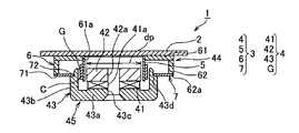
- FIGS. 1 is a side view showing an embodiment of the vibration transmission device
- FIG. 2 is a cross-sectional view taken along the line II of FIG. 1
- FIG. 3 is a bottom view of the vibration transmission device shown in FIG.
- a vibration transmission device 1 includes a plate-like contact portion 2 as a contact member that is brought into contact with, for example, a human body (contact body), and a drive device 3 for causing the contact portion 2 to vibrate. And.
- the drive device 3 is accommodated in a case, but this case is omitted in FIGS. 1 to 3.
- the “human body” includes human hands, torso, legs, feet, and the like, and the contact portion 2 is in direct or indirect contact with these.
- the size, shape, material (metal, synthetic resin, rubber, etc.) of the contact portion 2 can be set as appropriate.
- the driving device 3 includes a magnetic circuit 4 including a magnetic gap G, a voice coil bobbin 5 as a fixing member for fixing a coil C driven by the magnetic circuit 4, and another member (not shown) directly or on the voice coil bobbin 5. And a butterfly damper 7 for fixing the voice coil bobbin 5 via the connecting member 6.
- the coil C, the voice coil bobbin 5, the connecting member 6, the butterfly damper 7, and the contact part 2 constitute a vibration part (vibration system) 44.
- the voice coil bobbin (fixing member) 5 is substantially circular
- the butterfly damper 7 is substantially circular having an opening 74 (FIG. 3) concentric with the voice coil bobbin 5.
- the contact portion 2 is connected to a voice coil bobbin (fixing member) 5 or a connecting member 6.
- the magnetic circuit 4 is an internal magnetic circuit, and includes a magnet 41, a pole piece 42 in which one pole of the magnet 41 is magnetically coupled, and a yoke 43 in which the other pole of the magnet 41 is magnetically coupled. And a magnetic gap G.
- the magnet 41 is formed in a disc shape and has a through hole 41a in the center.
- the pole piece 42 is formed in a disc shape and is superimposed on the surface of the magnet 41 on the contact portion 2 side (one pole side).
- the pole piece 42 is also provided with a through hole 42 a that overlaps the through hole 41 a of the magnet 41.
- “Polepiece” is also called a plate.
- the diameter (dp) of the pole piece 42 is defined as 10 mm or more and 40 mm or less.
- the yoke 43 includes a bottom surface portion 43a that is superimposed on the surface of the magnet 41 that is away from the contact portion 2 (the other pole side), and a cylindrical yoke that is erected from the outer edge of the bottom surface portion 43a toward the contact portion 2 side. And a main body 43b.
- a through hole 43 c that overlaps the through hole 41 a of the magnet 41 is provided in the bottom surface portion 43 a.
- the magnet 41, the pole piece 42, and the yoke 43 are fixed.
- the yoke body 43 b extends to a position facing the pole piece 42.
- the magnetic gap G is a gap provided between the pole piece 42 and the yoke body 43b, and penetrates in the height direction Y1 of the coil C described later.
- the height direction Y1 of the coil C is the central axis direction of the coil C.
- the yoke 43, the magnet 41, and the pole piece 42 constitute a stationary part 45 including the magnetic circuit 4 having the magnetic gap G and the like.
- Two lead wires (not shown) are connected to the coil C, and the lead wires are connected to terminals (not shown) on the outer surface side of the magnetic circuit 4, for example.
- the voice coil bobbin 5 is formed in a cylindrical shape, and a coil C is wound around the outer surface thereof.
- the coil C is wound around the voice coil bobbin 5 with four or more turns.
- the coil C may be formed by winding a conductive wire around the voice coil bobbin 5 in a spiral shape. It is also possible to print the coil C on the voice coil bobbin 5.
- the end of the voice coil bobbin 5 on the magnetic circuit 4 side is inserted from the opening on the contact portion 2 side of the magnetic gap G, and the coil C is disposed in the magnetic gap G.
- the connecting member 6 is formed of a material having a rigidity equal to or higher than that of the voice coil bobbin 5 such as resin, for example, and has a plate-like support part 61 that supports the side away from the magnetic circuit 4 in the voice coil bobbin 5. And a cylindrical wall portion 62 that is suspended toward the circuit 4 side.
- the support portion 61 is provided in a shape having rounded rectangular corners when viewed from the magnetic circuit 4 side as shown in FIG. 3, and is separated from the magnetic circuit 4 of the voice coil bobbin 5 as shown in FIG. It has an insertion hole 61a for inserting the end on the other side.
- the end of the voice coil bobbin 5 on the side away from the magnetic circuit 4 is fixed to the inner peripheral surface of the insertion hole 61a by, for example, adhesion.
- the contact portion 2 is directly supported on the surface of the support portion 61 on the side away from the magnetic circuit 4.
- the wall portion 62 is formed in a cylindrical shape having a diameter substantially the same as the length in the short direction of the substantially rectangular support portion 61 described above.
- the butterfly damper 7 has an outer peripheral portion 71 connected and fixed to the wall portion 62, and an inner peripheral portion 72 connected and fixed to the yoke body 43b.
- a connecting portion on the wall 62 side with respect to the butterfly damper 7 is indicated by reference numeral 62a, and a connecting portion on the yoke body 43b side is indicated by reference numeral 43d.
- the substantially circular annular wall portion 62 itself may be collectively referred to as a connection portion.
- the wall 62 is formed in a substantially circular shape concentric with the voice coil bobbin (fixing member) 5.
- the butterfly damper 7 and the wall 62, and the butterfly damper 7 and the pole piece 42 are fixed using an adhesive or the like.
- the butterfly damper 7 is made of, for example, resin, and includes a ring-shaped inner peripheral portion 72, a ring-shaped outer peripheral portion 71, and a plurality of arm portions 73 extending from the inner peripheral portion 72 to the outer peripheral portion 71. Yes.
- the butterfly damper 7 can support the coil C so as to vibrate in the height direction Y1.
- the coil C is located in the magnetic gap G.
- the center in the height direction Y1 of the coil C, the center in the height direction Y1 of the magnetic gap G, and the butterfly damper 7 are located at substantially the same height, and the connecting portion 62a between the butterfly damper 7 and the wall portion 62 is also
- the magnetic gap G is located at the height between both ends in the height direction Y1. That is, a virtual plane created in the radial direction of the damper by the connecting portion 62a passes through the magnetic gap G and the coil C.
- the vibration transmission device 1 can be downsized.
- the vibration transmission device 1 can also be reduced in size by using the internal magnetic circuit 4.
- other dampers such as a plate shape and a coil shape can be used.
- the vibration transmission device 1 can obtain a large driving force for its small size, and can reliably transmit a large vibration to the user.
- the mechanical resonance sharpness value (Qm) of the vibration transmission device 1 is defined as 10 or more (Qm ⁇ 10).
- the diameter (dp) of the pole piece 42 is specified to be 10 mm or more and 40 mm or less.
- the frequency having the maximum vibration strength (maximum sound pressure) of the vibration unit 44 is defined to be smaller than the lowest resonance frequency of the vibration transmission device 1.
- the “vibrating portion 44” includes, for example, the voice coil bobbin 5, the coil C, the connecting member 6, and the contact portion 2.
- the order of “first, second, third” is merely for convenience of explanation.
- ⁇ (omega) is the angular velocity
- m0 is the weight (mass) of the vibration system
- rm is the mechanical resistance.
- the weight (mass) (m0) of the vibration system is mainly the weight (mass) of the diaphragm, the weight (mass) of the air that the diaphragm can push away, and the weight (mass) of the voice coil C including the voice coil bobbin 5.
- the amount is determined by the sum of Further, the mechanical resistance (rm) is a value determined by the physical property values of the diaphragm, the damper 7 and the like.
- the “diaphragm” is for convenience of explanation, and the vibration transmission device 1 includes the connecting member 6 and the contact portion 2.
- the vibration transmission device 1 having a large vibration system weight (m0) has a large mechanical resonance sharpness value (Qm).
- the vibration transmission device 1 having a large minimum resonance frequency (f0) has a large mechanical resonance sharpness value (Qm).
- the diameter (dp) of the pole piece 42 in the vibration transmission device 1 is defined as small as 10 mm or more and 40 mm or less, whereby the vibration transmission device 1 is miniaturized. For this reason, the weight of the diaphragm and the weight of the air that the diaphragm can push away are small. On the other hand, in order to obtain a large driving force, the weight of the voice coil C including the voice coil bobbin 5 is largely defined.
- a voice coil C having a large cross-sectional area and a long winding length is employed, or a voice coil C having a large cross-sectional area and a large winding diameter is employed.
- the mechanical resonance sharpness value (Qm) is largely defined.
- the vibration transmission device 1 focusing on the diameter (dp) of the pole piece 42 and the mechanical resonance sharpness value (Qm), the mechanical resonance sharpness value (Qm) is increased, so that the small vibration transmission device is obtained. Although it is 1, a large driving force can be obtained, and a large and realistic vibration can be reliably transmitted to the user.
- the mechanical resonance sharpness value (Qm) when the mechanical resonance sharpness value (Qm) is increased, the reverberation of vibration at a specific frequency is particularly increased.
- the input signal is a heart sound
- this reverberation is felt as vibration that gives the user a sense close to that of the actual heart sound. This will be described later with reference to FIG.
- the mechanical resonance sharpness value (Qm) can be measured, for example, using a speaker device measurement system of Klippel (Germany).
- a laser beam is applied to the diaphragm of the speaker device to be measured, and a signal whose frequency is swept is input to the speaker device and driven, the reflected light of the laser beam is read by a sensor, and the data is read.
- the Qm value is obtained and the Qm value is displayed.
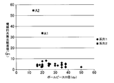
- FIG. 4 shows the result (scatter diagram) of the measurement of the relationship between the diameter (dp) of the pole piece 42 and the mechanical resonance sharpness value (Qm) of the vibration transmitting device 1.
- the diameter (dp) of the pole piece 42 is shown on the horizontal axis
- the mechanical resonance sharpness value (Qm) is shown on the vertical axis.
- the data of the series 1 shows the measurement result of the relationship between the diameter of the pole piece and the mechanical resonance sharpness value (Qm) of various speaker devices (not shown) instead of the vibration transmission device 1.
- the mechanical resonance sharpness value (Qm) in the speaker device is 10 (Qm) or less in a wide range where the diameter of the pole piece is approximately 15 to 50 mm.
- the difference between the speaker device and the vibration transmission device 1 is whether or not it has a vibration cone, that is, a diaphragm (the vibration transmission device does not have a cone).
- the structure is almost the same. Therefore, the measured value of the mechanical resonance sharpness value (Qm) using the speaker device can be used as a reference value in the vibration transmission device 1.
- the vibration transmission device 1 by setting the mechanical resonance sharpness value (Qm) to 10 or more, it is possible to obtain a larger vibration instead of the vibration in the speaker device, and reliably transmit a large vibration to the user. it can.
- the two data A1 and A2 of the series 2 are measured values in the first and second embodiments of the vibration transmission device 1.
- the pole piece diameter (dp) of Example 1 is 20 mm
- the pole piece diameter (dp) of Example 2 is 13 mm
- the mechanical resonance sharpness value (Qm) is 30 or more.
- Example 2 Comparing Example 1 and Example 2 in FIG. 4, the weight (m0) of the vibration system is smaller in Example 2 than in Example 1 (Example 2 is 4.2 g compared to 4.2 g in Example 1). However, since the minimum resonance frequency (f0) is large (Example 2 is 165 Hz compared to 76 Hz in Example 1), the mechanical resonance sharpness value (Qm) is large (Example). Example 3 is 54.3 with respect to 13.5.
- the pole piece diameters (dp) in the two examples of FIG. 4 are 20 mm and 13 mm.
- the mechanical resonance sharpness is obtained when the pole piece diameter (dp) is approximately 30 mm.
- the value (Qm) is about 10 but this is only for reference.
- the pole piece diameter (dp) is allowed to be about 40 mm at the maximum. Therefore, in this embodiment, the range of the pole piece diameter (dp) is defined as 10 mm or more and 40 mm or less.
- the number of winding layers of the voice coil is four, but the number of winding layers may be four or more.
- the small vibration transmission device 1 having a pole piece diameter (dp) of 10 mm or more and 40 mm or less by increasing the number of winding layers to 4 or more, the weight of the vibration system (vibration unit 44) is increased and mechanical resonance occurs.
- the sharpness value (Qm) can be increased, thereby obtaining a large vibration and reliably transmitting the vibration to the user.
- the weight (m0) of the vibration system (vibration unit 44) of Example 1 is 4.2 g, which is 0.13 times the total weight 32.0 g of the vibration transmission device 1. Further, the weight (m0) of the vibration system (vibration unit 44) of Example 2 is 2.0 g, which is 0.11 times the total weight 17.5 g of the vibration transmission device 1. As described above, the weight (mass) of the vibration system (vibration unit 44) of the vibration transmission device 1 is defined to be 1/10 or more of the weight (mass) of the vibration transmission device 1.
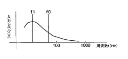
- FIG. 5 is a diagram illustrating that a signal having a frequency lower than the lowest resonance frequency (f0) is input to the vibration transmission device 1.
- the input level (V) is maximum at a frequency (f1) smaller than the lowest resonance frequency (f0).
- the horizontal axis represents the frequency f (Hz) and the vertical axis represents the input level (V).
- the “input level” is the strength of vibration or sound pressure.
- the frequency (f1) having a frequency smaller than the lowest resonance frequency (f0) and the highest input level is 1 ⁇ 2 or less of the lowest resonance frequency (f0).
- the minimum resonance frequency (f0) at the pole piece diameter (dp) of 20 mm in Example 1 shown in FIG. 4 is 76 Hz
- the minimum resonance frequency (f0) at the pole piece diameter (dp) of 13 mm in Example 2 is 165 Hz.
- the input level that is, the vibration strength (sound pressure) becomes maximum.
- the frequency (f1) at the maximum vibration strength (maximum sound pressure) vibrates (being driven) below the minimum resonance frequency (f0). Further, it can be mentioned that the frequency (f1) of the maximum vibration strength (maximum sound pressure) vibrates (drives) at 1/2 or less of the minimum resonance frequency (f0).
- the input may be a sine wave, a rectangular wave, a triangular wave, or the like as long as the frequency (f1) is lower than the lowest resonance frequency (f0), or a tone burst (on-off repeated wave with a predetermined period).
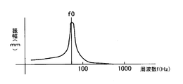
- FIG. 6 is a diagram showing the amplitude (mm) at which the vibration system (vibration unit 44) of the vibration transmission device 1 vibrates with respect to a certain input level (V).
- the horizontal axis represents frequency f (Hz) and the vertical axis represents amplitude (mm).
- the slope of the amplitude suddenly increases near the lowest resonance frequency (f0), and the amplitude sharply increases.
- the lowest resonance frequency (f0) of Example 1 in FIG. 4 is 76 Hz, and the mechanical resonance sharpness value (Qm) is 33.5, whereas the lowest resonance frequency (f0) of Example 2 is shown.
- the input level (V) that is, the vibration strength becomes maximum at a frequency f1 smaller than the lowest resonance frequency (f0).
- the vibration transmission device 1 can be used as a game machine, for example. That is, in addition to video and sound related to the game, vibrations can be applied to human hands, torso, legs, and the like, thereby giving the game a sense of realism, liveliness, or reality.
- the entire coil C is disposed in the magnetic gap G when the vibration transmission device 1 is not driven. However, for example, only a part of the coil C is disposed in the magnetic gap G. May be.
- An imaginary plane created in the damper radial direction by the connecting portion 62 a between the connecting member 6 and the damper 7 passes through the coil C or the magnetic gap G.
- the coil C moves to the magnetic circuit 4 side, and the height direction center of the coil C and the height of the magnetic gap G The coil C is driven by approaching the center of the direction.
- all of the coil C may be disposed outside the magnetic gap G when the vibration transmission device 1 is not driven.
- the connection part 62a of the butterfly damper 7 and the connecting member 6 is closer to the contact part 2 side than the end part on the contact part 2 side in the height direction Y1 of the magnetic gap G.
- the connecting portion 62a between the butterfly damper 7 and the connecting member 6 is located at the height between both ends of the coil C in the height direction Y1. Further, the positions of the outer peripheral portion 71 and the inner peripheral portion 72 of the butterfly damper 7 in the height direction are different. An imaginary plane created in the damper radial direction by the connecting portion 62 a between the connecting member 6 and the damper 7 passes through the magnetic gap G.
- the vibration transmission device 1 including the inner magnet type magnetic circuit 4 has been described.
- the characteristic part of the vibration transmission device 1 is a vibration including an outer magnet type magnetic circuit (not shown). It can also be applied to a transmission device.
- FIG. 7 shows an embodiment of a vibration transmission device provided with an external magnetic type magnetic circuit.
- This vibration transmission device 1A includes a pole piece 42A erected at the center of the yoke 43A, a magnet 41A disposed near the outer periphery of the yoke 43A, a plate 75 disposed on the magnet 41A, and a pole piece 42A.
- Voice coil bobbins (fixed members) 5 and coils C disposed between the plates 75 (inside the magnetic gap G), a damper 7 connected to the outer peripheral side of the plate 75, and a connecting member connected closer to the outer periphery of the damper 7 6A cylindrical wall part 62 and the contact part 2 fixed to the voice coil bobbin 5 and the connection member 6A are provided.
- the magnetic circuit 4A of the vibration transmission device 1A includes a magnet 41A, a yoke 43A including a pole piece 42A, and a plate 75, and the inner diameter side of the damper 7 is connected to the plate 75.
- the symbol dp indicates the diameter of the pole piece 42A.
- the voice coil bobbin 5, the connecting member 6, and the contact portion 2 are formed separately.
- the voice coil bobbin 5 and the connecting member 6 may be formed integrally, or the connecting member 6 and the contact portion. 2 may be formed integrally, or the voice coil bobbin 5, the connecting member 6, and the contact portion 2 may be formed integrally.
- the vibration transmission device of the present invention can be appropriately modified according to conventionally known knowledge. As long as the modification still includes the configuration of the vibration transmission device of the present invention, it is of course included in the scope of the present invention.
Landscapes
- Physics & Mathematics (AREA)
- Electromagnetism (AREA)
- Engineering & Computer Science (AREA)
- Mechanical Engineering (AREA)
- Apparatuses For Generation Of Mechanical Vibrations (AREA)
Abstract
従来の振動伝達装置における、大きな駆動力を得ることが難しく、それにより、使用者に大きな振動を確実に伝えることが難しいという問題を解消することが目的の一例として挙げられる。 この目的を達成するために、振動伝達装置(1)は、コイル(C)、及び、接触体に接触する接触部(2)、を含む振動部(44)と、磁石(41)を含む磁気回路(4)と、を備え、機械的共振尖鋭度値(Qm)が10以上に規定されている。
Description
本発明は、振動伝達装置に関するものである。
例えば特許文献1(図示せず)には、携帯機器に組み込んだ振動発生装置を動作させて、振動によって通報するに際し、振動発生装置の振動周波数を掃引させて携帯機器のケーシングを振動させることにより、駆動信号周波数の掃引が携帯機器のケーシングの共振周波数の付近になった時に、ピークの大きな体感振動が発生し、確実に通報することができることが記載されている。
この振動発生装置は、円筒形の枠体内に、センタポールと外周部とを有するヨークを配置し、外周部の内面に環状の磁石を固定し、磁石とセンタポールとの間に円筒形のコイルを配置し、ヨークをハット状の弾性体で枠体の一端に支持固定し、コイルを板状の弾性体で枠体の他端に支持固定した構造を備えている。
また、特許文献2(図示せず)には、ヨーク、永久磁石、プレート、中心軸からなる磁気回路と、コイルと駆動回路部とで構成され、駆動回路部は、磁気回路とコイルとの振動共振周波数より5Hz~50Hz高い周波数で駆動されることが記載されている。
同特許文献2には、振動共振周波数f0と一致する入力周波数を印加すれば、最も効率良い振動が得られるが、振動共振周波数を利用して振動させると、入力を切った後の振動の余韻が大きく、特に短いサイクルの振動で触覚に訴えようとするクリック感発生器等に使用する場合には、めりはりの弱い振動となってしまうことが記載されている。
しかしながら、前記従来の振動発生装置や振動アクチュエータといった振動伝達装置においては、大きな駆動力を得ることが難しかった。そのために、使用者に大きな振動を確実に伝えることが難しかった。特に、手で持てるあるいは手の平に載る程度に小型化した振動伝達装置においては、なおさら大きな振動を得ることが難しかった。
本発明が解決しようとする課題としては、前記従来の振動伝達装置における、大きな駆動力を得ることが難しく、それにより、使用者に大きな振動を確実に伝えることが難しいという問題が一例として挙げられる。
請求項1記載の振動伝達装置は、コイル、及び、接触体に接触する接触部、を含む振動部と、磁石を含む磁気回路と、を備え、機械的共振尖鋭度値(Qm)が10以上であることを特徴とする。
以下に、本発明の一実施形態に係る振動伝達装置について説明する。
本発明の実施形態に係る振動伝達装置は、コイル、及び、接触体に接触する接触部、を含む振動部と、磁石を含む磁気回路と、を備え、機械的共振尖鋭度値(Qm)が10以上に規定されている。この構成により、大きな駆動力を得ることができ、使用者に大きな振動を確実に伝えることができる。
また、前記磁気回路はポールピースを備え、ポールピースの径(dp)が10mm以上、40mm以下であることが好ましい。この構成により、手で持てるあるいは手の平に載る程度に小型化した振動伝達装置において、大きな駆動力を得ることができ、使用者に大きな振動を確実に伝えることができる。
また、前記振動部の重量は、装置全体の重量の1/10以上であることが好ましい。この構成により、大きな駆動力を得ることができ、使用者に大きな振動を確実に伝えることができる。
また、振動伝達装置における最大振動強さの周波数(f1)が、最低共振周波数(f0)以下である(以下で駆動される)ことが好ましい。この構成により、一層大きな駆動力を得ることができ、使用者に一層大きな振動を確実に伝えることができる。
また、前記機械的共振尖鋭度値(Qm)は、30以上であることが好ましい。この構成により、一層大きな駆動力を得ることができ、使用者に一層大きな振動を確実に伝えることができる。また、最大振動強さの周波数(f1)が最低共振周波数(f0)の1/2以下である(以下で駆動される)ことが一層好ましい。この構成により、一層大きな駆動力を得ることができ、使用者に一層大きな振動を確実に伝えることができる。
また、前記コイルはボイスコイルボビンに4層以上に巻かれていることが好ましい。この構成により、振動系の重量(質量)が増加して、大きな駆動力を得ることができ、使用者に大きな振動を確実に伝えることができる。
また、前記振動伝達装置は、磁気ギャップを備える前記磁気回路を含む静止部と、前記振動部及び静止部を接続するダンパと、を備え、ダンパの内径側が静止部に接続され、ダンパの外径側が振動部に接続されていることが好ましい。また、ダンパの内径側は磁気回路に接続されていることが好ましい。これらの構成によって、大きな外径の接触部をダンパの外側部分で安定に支えて、コイルの振れを抑止することができる。
また、前記磁気回路は、磁石とヨークを備え、前記ダンパの内径側がヨークに接続されている(内磁型)ことが好ましい。あるいは、前記磁気回路は、磁石と、ポールピースを備えたヨークと、プレートとを備え、前記ダンパの内径側がプレートに接続されている(外磁型)ことが好ましい。
また、前記振動部は、コイルと、コイルを固定する固定部材と、固定部材に直接又は他の部材を介して連結されている連結部材と、を備え、前記ダンパの外径側が連結部材に接続されていることが好ましい。固定部材はボイスコイルボビンを含む。
また、前記連結部材が、前記ダンパに接続する接続部を備え、接続部によってダンパ径方向に作られる仮想平面が、前記磁気ギャップを通ることが好ましい。この構成によって、接触部に接触体が接触しても、コイルが横揺れするのを抑制することができる。
あるいは、前記連結部材が、前記ダンパに接続する接続部を備え、接続部によってダンパ径方向に作られる仮想平面が、前記コイルを通ることが好ましい。この構成によって、接触部に接触体が接触しても、コイルが横揺れするのを抑制することができる。
また、前記固定部材は略円形であり、前記ダンパは、固定部材と同心の開口を有する略円形であることが好ましい。また、前記接続部は、前記固定部材と同心の略円形であることが好ましい。これらの構成によって、接触部に接触体が任意の方向から接触しても、この振動伝達装置が受ける力が方向によらず一定となる。
また、前記振動部における接触部は、前記固定部材もしくは前記連結部材に接続されていることが好ましい。また、前記ダンパは、複数の腕部を有する蝶ダンパであることが好ましい。
以下に、図1~図3に基づいて、本発明の一実施例に係る振動伝達装置の構造について説明する。図1は、振動伝達装置の一実施例を示す側面図、図2は、図1のI-I線断面図、図3は、図1に示す振動伝達装置の底面図である。
図1~図3に示すように、振動伝達装置1は、例えば人体等(接触体)に接触させる接触部材としての板状の接触部2と、この接触部2を振動させるための駆動装置3と、を備えている。駆動装置3は、ケース内に収容されているが、図1~図3ではこのケースについては省略している。「人体」とは人間の手や胴体、脚、足等を含み、これらに接触部2が直接的又は間接的に接触する。接触部2の大きさ、形状、材質(金属、合成樹脂、ゴム等)等は適宜設定可能である。
駆動装置3は、磁気ギャップGを含む磁気回路4と、磁気回路4によって駆動されるコイルCを固定する固定部材としてのボイスコイルボビン5と、ボイスコイルボビン5に直接又は他の部材(図示せず)を介して連結されている連結部材6と、連結部材6を介してボイスコイルボビン5を固定する蝶ダンパ7と、を備えている。
例えば、コイルCとボイスコイルボビン5と連結部材6と蝶ダンパ7と接触部2とで、振動部(振動系)44が構成されている。ボイスコイルボビン(固定部材)5は略円形であり、蝶ダンパ7は、ボイスコイルボビン5と同心の開口74(図3)を有する略円形である。接触部2は、ボイスコイルボビン(固定部材)5もしくは連結部材6と接続されている。
前記磁気回路4は、内磁型の磁気回路であり、磁石41と、磁石41の一極が磁気的に結合されたポールピース42と、磁石41の他極が磁気的に結合されたヨーク43と、磁気ギャップGと、を含んでいる。磁石41は、円板状に形成され、中央に貫通孔41aを有している。ポールピース42は、円板状に形成され、磁石41の接触部2側(一極側)の面に重ねられる。このポールピース42にも、磁石41の貫通孔41aと重なる貫通孔42aが設けられている。
「ポールピース」はプレートとも呼称される。ポールピース42の径(dp)は10mm以上、40mm以下に規定されている。
ヨーク43は、磁石41の接触部2から離れた側(他極側)の面に重ねられる底面部43aと、底面部43aの外縁から接触部2側に向かって立設された筒状のヨーク本体43bと、から構成されている。底面部43aには、磁石41の貫通孔41aと重なる貫通孔43cが設けられている。磁石41、ポールピース42及びヨーク43は固定されている。前記ヨーク本体43bは、ポールピース42と対向する位置まで延在している。
磁気ギャップGは、ポールピース42とヨーク本体43bとの間に設けられるギャップであり、後述するコイルCの高さ方向Y1に貫通している。コイルCの高さ方向Y1とは、コイルCの中心軸方向である。ヨーク43と磁石41とポールピース42とで、磁気ギャップGを備える磁気回路4等を含む静止部45が構成されている。コイルCには不図示の2本のリード線が接続され、リード線は例えば磁気回路4の外面側の不図示の各端子に接続されている。
ボイスコイルボビン5は、筒状に形成され、その外側面にコイルCが巻かれている。コイルCはボイスコイルボビン5に4層ないしそれ以上の巻き数で巻かれている。コイルCは、ボイスコイルボビン5に導線をらせん状に巻いて形成されていてもよい。ボイスコイルボビン5にコイルCをプリントして設けることも可能である。このボイスコイルボビン5の磁気回路4側の端部を磁気ギャップGの接触部2側の開口から挿入して、コイルCを磁気ギャップG内に配置する。この状態で、コイルCに通電すると、コイルCに高さ方向Y1の振動力が発生する。
連結部材6は、例えば樹脂などボイスコイルボビン5と同等以上の剛性を有する材料で形成され、ボイスコイルボビン5における磁気回路4から離れた側を支持する板状の支持部61と、支持部61から磁気回路4側に向かって垂設された筒状の壁部62と、を一体に含んでいる。本実施例で支持部61は、図3に示すように、磁気回路4側から見て長方形の角を丸くした形状に設けられ、図2に示すように、ボイスコイルボビン5の磁気回路4から離れた側の端部を挿入する挿入孔61aを有している。
ボイスコイルボビン5の磁気回路4から離れた側の端部は、挿入孔61aの内周面に例えば接着により固定されている。また、支持部61の磁気回路4から離れた側の面に接触部2が直接、支持されている。前記壁部62は、上述した略長方形状の支持部61の短手方向の長さとほぼ同じ直径の円筒状に形成されている。
蝶ダンパ7は、その外周部71が壁部62に接続・固定され、その内周部72がヨーク本体43bに接続・固定されている。蝶ダンパ7に対する壁部62側の接続部を符号62aで示し、ヨーク本体43b側の接続部を符号43dで示している。略円形環状の壁部62自体を接続部と総称することも可能である。壁部62はボイスコイルボビン(固定部材)5と同心の略円形に形成されている。
蝶ダンパ7と壁部62、及び蝶ダンパ7とポールピース42の固定は、接着材などを用いて行われる。蝶ダンパ7は、例えば樹脂などから構成され、リング状の内周部72と、リング状の外周部71と、これら内周部72から外周部71にかけて伸びる複数の腕部73と、を備えている。この蝶ダンパ7により、コイルCを高さ方向Y1に振動可能に支持することができる。
図2において、コイルCは磁気ギャップG内に位置している。コイルCの高さ方向Y1の中心と、磁気ギャップGの高さ方向Y1の中心と、蝶ダンパ7と、が略同じ高さに位置し、蝶ダンパ7と壁部62との接続部62aも、磁気ギャップGの高さ方向Y1両端間の高さに位置している。すなわち、接続部62aによってダンパ径方向に作られる仮想平面が、磁気ギャップGを通ると共にコイルCを通っている。
使用者が不図示のスイッチを入れると、コイルCに駆動電流が流れて、コイルCがY1方向に振動し、接触部2がY1方向に振動する。蝶ダンパ7と壁部62との接続部62aを、コイルCの高さ方向Y1両端間の高さに位置させているため、複数のダンパを用いなくてもコイルCに発生する横揺れを抑えることができ、振動伝達装置1の小型化を図ることができる。内磁型の磁気回路4を用いたことによっても、振動伝達装置1の小型化を図ることができる。なお、蝶ダンパ7に代えて板状やコイル状等の他のダンパを用いることも可能である。
以下に、前記振動伝達装置1のさらなる特徴について説明する。
前記振動伝達装置1は、小型である割に大きな駆動力を得ることができ、使用者に大きな振動を確実に伝えることができるものである。
このための構成として、第1に、前記振動伝達装置1の機械的共振尖鋭度値(Qm)が10以上(Qm≧10)に規定されていることが挙げられる。
また、第2に、ポールピース42の径(dp)が、10mm以上、40mm以下に規定されていることが挙げられる。
また、第3に、振動部44の最大振動強さ(最大音圧)をもつ周波数が、振動伝達装置1の最低共振周波数よりも小さく規定されていることが挙げられる。ここで、「振動部44」とは、例えば、ボイスコイルボビン5とコイルCと連結部材6と接触部2とを備える。また、「第1に、第2に、第3に」の順位は単に説明の便宜上のものである。
前記機械的共振尖鋭度値(Qm)とは、Qm=ωm0/rm で表される特性値である。ここで、ω(オメガ)は角速度、m0は振動系の重量(質量)、rmは機械抵抗である。オメガは、ω=2πf0で表される(f0は最低共振周波数である)。
また、振動系の重量(質量)(m0)は、主に振動板の重量(質量)と、振動板が押しのける空気の重量(質量)と、ボイスコイルボビン5を含むボイスコイルCの重量(質量)との総和で決まる量である。また、機械抵抗(rm)は、振動板やダンパ7等の物性値で決まる値である。なお、「振動板」とは、説明の便宜上のもので、振動伝達装置1においては、連結部材6や接触部2を含むものである。
従って、振動系の重量(m0)が大きい振動伝達装置1は、機械的共振尖鋭度値(Qm)が大きくなる。また、振動系の重量(m0)と機械抵抗(rm)とが一定である場合は、最低共振周波数(f0)が大きい振動伝達装置1は、機械的共振尖鋭度値(Qm)が大きくなる。これらについては図4を用いて後述する。
前記振動伝達装置1におけるポールピース42の径(dp)は、10mm以上、40mm以下と小さく規定されており、それにより、振動伝達装置1が小型化されている。このため、振動板の重量や、振動板が押しのける空気の重量は小さい。それに対し、大きな駆動力を得るために、ボイスコイルボビン5を含むボイスコイルCの重量を大きく規定している。
すなわち、大きな駆動力を得るために、断面積が大きく、巻線長の長いボイスコイルCを採用して、あるいは断面積が大きく、巻線径の太いボイスコイルCを採用して、振動系の重量(m0)を大きくすることで、機械的共振尖鋭度値(Qm)を大きく規定している。
前記振動伝達装置1において、ポールピース42の径(dp)と機械的共振尖鋭度値(Qm)とに着目して、機械的共振尖鋭度値(Qm)を高めることで、小型の振動伝達装置1でありながら、大きな駆動力を得ることができ、使用者に大きくリアルな振動を確実に伝えることができる。
また、機械的共振尖鋭度値(Qm)を大きくすると、特定の周波数の振動の余韻が特に大きくなる。入力信号が例えば心音の場合、この余韻は使用者に実際の心音に近い感覚を与える振動として感じられることが実験等から明らかになった。これについては図6を用いて後述する。
なお、機械的共振尖鋭度値(Qm)の測定は、例えばクリッペル社(ドイツ)のスピーカ装置測定システムを用いて行うことができる。このスピーカ装置測定システムでは、測定するスピーカ装置の振動板にレーザ光線を当て、スピーカ装置に、周波数をスイープさせた信号を入力して駆動し、レーザ光線の反射光をセンサで読み取り、そのデータをもとに振動板の動きを解析してQm値を求め、Qm値を表示する。前記したQm=ωm0/rmの公式に、ωやm0、rmの値を代入してQm値を計算することも可能ではあるが、実際的ではない。
図4は、ポールピース42の口径(dp)と振動伝達装置1の機械的共振尖鋭度値(Qm)の関係を計測した結果(散布図)を示すものである。図4において、ポールピース42の口径(dp)を横軸に示し、機械的共振尖鋭度値(Qm)を縦軸に示している。
図4において、系列1のデータは、振動伝達装置1ではなく、不図示の種々のスピーカ装置のポールピースの口径と機械的共振尖鋭度値(Qm)の関係の計測結果を示すものである。スピーカ装置における機械的共振尖鋭度値(Qm)は、ポールピースの口径がほぼ15~50mmの広い範囲において、10(Qm)以下である。
スピーカ装置と振動伝達装置1の違いは、振動用のコーンすなわち振動板を有しているか否かの違いであり(振動伝達装置はコーンを有していない)、その他の磁気回路4等の内部構造は概ね同じである。従って、スピーカ装置を用いた機械的共振尖鋭度値(Qm)の計測値は振動伝達装置1において参考値として使用可能とある。
振動伝達装置1において、機械的共振尖鋭度値(Qm)を10以上とすることで、スピーカ装置における振動ではなく、より大きな振動を得ることができ、使用者により大きな振動を確実に伝えることができる。
そして、複数の使用者に対して行った感覚的な確認実験の結果、機械的共振尖鋭度値(Qm)が10を超えれば、大きな駆動力で駆動される特定の周波数の振動の余韻によって、使用者にとってはリアルな振動として感じられることが分かった。
さらに、機械的共振尖鋭度値(Qm)が30以上であれば、入力信号が例えば心音(心臓の鼓動)の場合、この余韻は使用者に実際の心音にさらに近い感覚を与える振動として感じられることが実験等から明かになった。
図4において、系列2の2つデータA1,A2が振動伝達装置1の実施例1,2における計測値である。図4で、Qm=33.5の計測値A1が実施例1におけるものであり、Qm=54.3の計測値A2が実施例2におけるものである。
以下に、実施例1,2における各振動伝達装置1の仕様を左右に並べて記載する。
<実施例1> <実施例2>
ポールピース42の径dp:20mm 13mm
巻線径(銅丸線): 0.14mm 0.12mm
巻線重量: 1.0g 0.5g
巻線最小内径: 20.5mm 13.4mm
巻数: 100回 110回
巻幅: 5.0mm 4.7mm
層数: 4 4
巻線全長: 6.7m 4.8mm
振動系の重量m0: 4.2g 2.0g
総重量: 32.0g 17.5g
定格インピーダンス: 8Ω 8Ω
最低共振周波数f0: 76Hz 165Hz
機械的共振尖鋭度値Qm: 33.5 54.3
ポールピース42の径dp:20mm 13mm
巻線径(銅丸線): 0.14mm 0.12mm
巻線重量: 1.0g 0.5g
巻線最小内径: 20.5mm 13.4mm
巻数: 100回 110回
巻幅: 5.0mm 4.7mm
層数: 4 4
巻線全長: 6.7m 4.8mm
振動系の重量m0: 4.2g 2.0g
総重量: 32.0g 17.5g
定格インピーダンス: 8Ω 8Ω
最低共振周波数f0: 76Hz 165Hz
機械的共振尖鋭度値Qm: 33.5 54.3
図4における実施例1のポールピース径(dp)は20mm、実施例2のポールピース径(dp)は13mmで、何れも機械的共振尖鋭度値(Qm)が30以上となっている。
図4の実施例1と実施例2を比較すると、実施例2では、実施例1に比べて、振動系の重量(m0)は小さい(実施例1の4.2gに対して実施例2は2.0gである)が、最低共振周波数(f0)が大きい(実施例1の76Hzに対して実施例2は165Hzである)ために、機械的共振尖鋭度値(Qm)が大きく(実施例1の33.5に対して実施例2は54.3に)なっている。
もし仮に、実施例1,2の最低共振周波数(f0)及び上記機械抵抗(rm)が同じであれば、前記したQm=ωm0/rm、 ω=2πf0の公式より、振動系の重量(m0)の大きな(実施例2の2.0gに対して実施例1は4.2gである)実施例1の方が、機械的共振尖鋭度値(Qm)が大きくなる。
図4の2つの実施例におけるポールピース径(dp)は20mmと13mmであり、例えば2つのデータA1,A2を直線で結ぶと、ポールピース径(dp)が概ね30mmにおいて、機械的共振尖鋭度値(Qm)が概ね10程度となるが、これはあくまでも参考程度のものである。例えば、振動伝達装置1の大きさを手の中に持てるあるいは手の平に載る程度までと規定した場合、ポールピース径(dp)は最大で40mm程度まで許容される。従って、本実施例においては、ポールピース径(dp)の範囲を10mm以上、40mm以下と規定している。
もし仮に、最低共振周波数(f0)及び前記機械抵抗(rm)が同じであれば、ポールピース径(dp)を増加させることで、振動系の重量(m0)が増し、機械的共振尖鋭度値(Qm)が増大するので、ポールピース径(dp)を30mmないし40mmに規定することで、さらに大きな振動を得て、使用者に振動を確実に伝えることができる。
また、実施例1,2ではボイスコイルの巻線の層数を4としているが、巻線の層数は4以上であればよい。ポールピース径(dp)が10mm以上、40mm以下の小型の振動伝達装置1において、巻線の層数を4以上とすることで、振動系(振動部44)の重量を増して、機械的共振尖鋭度値(Qm)を増加させ、それにより、大きな振動を得て、使用者に振動を確実に伝えることができる。
また、実施例1の振動系(振動部44)の重量(m0)は4.2gであり、振動伝達装置1の総重量32.0gの0.13倍である。また、実施例2の振動系(振動部44)の重量(m0)は2.0gであり、振動伝達装置1の総重量17.5gの0.11倍である。このように、振動伝達装置1の振動系(振動部44)の重量(質量)は、振動伝達装置1の重量(質量)の1/10以上に規定されている。
図5は、最低共振周波数(f0)よりも周波数の小さな信号が前記振動伝達装置1に入力されることを示す図である。最低共振周波数(f0)よりも小さな周波数(f1)において入力レベル(V)が最大となっている。図5で、横軸が周波数f(Hz)、縦軸が入力レベル(V)である。「入力レベル」とは振動の強さ又は音圧のことである。
図5の例において、最低共振周波数(f0)よりも周波数が小さく、最も入力レベルが大きな周波数(f1)は、最低共振周波数(f0)の1/2以下である。前記図4に示した実施例1のポールピース径(dp)20mmにおける最低共振周波数(f0)は76Hz、実施例2のポールピース径(dp)13mmにおける最低共振周波数(f0)は165Hzであるが、それよりも小さな周波数f1において、入力レベルすなわち振動の強さ(音圧)が最大となる。
このように、前記振動伝達装置1の特徴として、最大振動強さ(最大音圧)における周波数(f1)が、最低共振周波数(f0)以下で振動する(駆動される)ことが挙げられる。また、最大振動強さ(最大音圧)の周波数(f1)が、最低共振周波数(f0)の1/2以下で振動する(駆動される)ことが挙げられる。なお入力は、最低共振周波数(f0)よりも小さな周波数(f1)であれば、正弦波、矩形波、三角波等でもよいし、またトーンバースト(所定の周期でのオンオフの繰り返し波)でもよい。
図6は、一定の入力レベル(V)に対して、振動伝達装置1の振動系(振動部44)が振動する振幅(mm)を示す図である。図6で、横軸が周波数f(Hz)、縦軸が振幅(mm)である。
図6の如く、最低共振周波数(f0)の付近で振幅の傾きが急峻に大きくなって、振幅が急峻に増大している。前記機械的共振尖鋭度値(Qm)が大きければ大きい程この傾きが急峻になり、振幅が急峻に増大する。
図6に関し、前記図4における実施例1の最低共振周波数(f0)は76Hz、同じく機械的共振尖鋭度値(Qm)は33.5であり、それに対し、実施例2の最低共振周波数(f0)は165Hz、同じく機械的共振尖鋭度値(Qm)は54.3で、実施例1の値よりも大きくなっている。振幅は最低共振周波数(f0)において急峻に大きくなるが、図5の如く、最低共振周波数(f0)よりも小さな周波数f1において、入力レベル(V)すなわち振動強さは最大となる。
前記振動伝達装置1は、用途として例えばゲーム機に使用することができる。すなわち、ゲームに関する映像や音に加え、人の手や胴体や脚等に振動を与えて、ゲームに臨場感や躍動感、あるいはリアリティを与えることができる。
なお、前記実施例においては、振動伝達装置1の非駆動状態において、コイルCの全部を磁気ギャップG内に配置したが、例えば、コイルCの一部だけを磁気ギャップG内に配置するようにしてもよい。連結部材6とダンパ7との接続部62aによってダンパ径方向に作られる仮想平面はコイルC又は磁気ギャップGを通る。この場合は、振動伝達装置1を使用するために接触部2を人体等に押し付けると、コイルCが磁気回路4側に移動して、コイルCの高さ方向の中心と磁気ギャップGの高さ方向の中心とが近づいて、コイルCが駆動される。
また、振動伝達装置1の非駆動状態において、コイルCの全部が磁気ギャップG外に配置されていてもよい。このとき、蝶ダンパ7と連結部材6の接続部62aは、磁気ギャップGの高さ方向Y1の接触部2側の端部よりも接触部2側にある。蝶ダンパ7と連結部材6との接続部62aは、コイルCの高さ方向Y1の両端間の高さに位置している。また、蝶ダンパ7の外周部71及び内周部72の高さ方向の位置が異なっている。連結部材6とダンパ7との接続部62aによってダンパ径方向に作られる仮想平面は磁気ギャップGを通る。
また、前記実施例においては、内磁型の磁気回路4を備えた振動伝達装置1について説明したが、前記振動伝達装置1の特徴部分は、不図示の外磁型の磁気回路を備えた振動伝達装置にも適用可能である。
図7は、外磁型の磁気回路を備えた振動伝達装置の一実施例を示すものである。この振動伝達装置1Aは、ヨーク43Aの中央に立設されたポールピース42Aと、ヨーク43Aの外周寄りに配置された磁石41Aと、磁石41Aの上に配置されたプレート75と、ポールピース42Aとプレート75の間(磁気ギャップG内)に配置されたボイスコイルボビン(固定部材)5及びコイルCと、プレート75の外周側に接続されたダンパ7と、ダンパ7の外周寄りに接続された連結部材6Aの筒状壁部62と、ボイスコイルボビン5や連結部材6Aに固定された接触部2とを備えるものである。
振動伝達装置1Aの磁気回路4Aは、磁石41Aと、ポールピース42Aを備えたヨーク43Aと、プレート75とを備え、ダンパ7の内径側がプレート75に接続されている。図7で、符号dpはポールピース42Aの径を示している。
また、前記各実施例においては、ボイスコイルボビン5と連結部材6と接触部2とを別体に形成したが、ボイスコイルボビン5と連結部材6とを一体に形成したり、連結部材6と接触部2とを一体に形成したり、ボイスコイルボビン5と連結部材6と接触部2とを一体に形成することも可能である。
その他、従来公知の知見に従い、本発明の振動伝達装置を適宜改変することができる。かかる改変によってもなお本発明の振動伝達装置の構成を具備する限り、勿論、本発明の範疇に含まれるもの
1 振動伝達装置
2 接触部
4 磁気回路
5 ボイスコイルボビン(固定部材)
6 連結部材
7 ダンパ
41 磁石
42 ポールピース
43 ヨーク
44 振動部
45 静止部
62a 接続部
73 腕部
74 開口
75 プレート
C コイル
G 磁気ギャップ
f0 最低共振周波数
f1 最大振動強さの周波数
2 接触部
4 磁気回路
5 ボイスコイルボビン(固定部材)
6 連結部材
7 ダンパ
41 磁石
42 ポールピース
43 ヨーク
44 振動部
45 静止部
62a 接続部
73 腕部
74 開口
75 プレート
C コイル
G 磁気ギャップ
f0 最低共振周波数
f1 最大振動強さの周波数
Claims (18)
- コイル、及び、接触体に接触する接触部、を含む振動部と、
磁石を含む磁気回路と、
を備え、
機械的共振尖鋭度値(Qm)が10以上であることを特徴とする振動伝達装置。 - 前記磁気回路はポールピースを備え、
前記ポールピースの径(dp)が10mm以上、40mm以下であることを特徴とする請求項1記載の振動伝達装置。 - 前記振動部の重量は、装置全体の重量の1/10以上であることを特徴とする請求項1記載の振動伝達装置。
- 最大振動強さの周波数(f1)が最低共振周波数(f0)以下であることを特徴とする請求項1記載の振動伝達装置。
- 前記機械的共振尖鋭度値(Qm)が30以上であることを特徴とする請求項1記載の振動伝達装置。
- 最大振動強さの周波数(f1)が最低共振周波数(f0)の1/2以下であることを特徴とする請求項1記載の振動伝達装置。
- 前記コイルはボイスコイルボビンに4層以上に巻かれていることを特徴とする請求項1記載の振動伝達装置。
- 磁気ギャップを備える前記磁気回路を含む静止部と、
前記振動部及び前記静止部を接続するダンパと、
を備え、
前記ダンパの内径側が前記静止部に接続され、
前記ダンパの外径側が前記振動部に接続されていることを特徴とする請求項1記載の振動伝達装置。 - 前記ダンパの内径側が前記磁気回路に接続されていることを特徴とする請求項8記載の振動伝達装置。
- 前記磁気回路は、磁石とヨークを備え、
前記ダンパの内径側が前記ヨークに接続されていることを特徴とする請求項8記載の振動伝達装置。 - 前記磁気回路は、磁石と、ポールピースを備えたヨークと、プレートとを備え、
前記ダンパの内径側が前記プレートに接続されていることを特徴とする請求項8記載の振動伝達装置。 - 前記振動部は、
コイルと、
前記コイルを固定する固定部材と、
前記固定部材に直接又は他の部材を介して連結されている連結部材と、
を備え、
前記ダンパの外径側が前記連結部材に接続されていることを特徴とする請求項8記載の振動伝達装置。 - 前記連結部材が、前記ダンパと接続する接続部を備え、
前記接続部によってダンパ径方向に作られる仮想平面が、前記磁気ギャップを通ることを特徴とする請求項12記載の振動伝達装置。 - 前記連結部材が、前記ダンパに接続する接続部を備え、
前記接続部によってダンパ径方向に作られる仮想平面が、前記コイルを通ることを特徴とする請求項12記載の振動伝達装置。 - 前記固定部材は略円形であり、
前記ダンパは、前記固定部材と同心の開口を有する略円形であることを特徴とする請求項12記載の振動伝達装置。 - 前記接続部は、前記固定部材と同心の略円形であることを特徴とする請求項13記載の振動伝達装置。
- 前記振動部における接触部は、前記支持部材もしくは前記連結部材に接続されていることを特徴とする請求項12記載の振動伝達装置。
- 前記ダンパは、複数の腕部を有する蝶ダンパであることを特徴とする請求項8記載の振動伝達装置。
Priority Applications (1)
| Application Number | Priority Date | Filing Date | Title |
|---|---|---|---|
| PCT/JP2015/053079 WO2016125265A1 (ja) | 2015-02-04 | 2015-02-04 | 振動伝達装置 |
Applications Claiming Priority (1)
| Application Number | Priority Date | Filing Date | Title |
|---|---|---|---|
| PCT/JP2015/053079 WO2016125265A1 (ja) | 2015-02-04 | 2015-02-04 | 振動伝達装置 |
Publications (1)
| Publication Number | Publication Date |
|---|---|
| WO2016125265A1 true WO2016125265A1 (ja) | 2016-08-11 |
Family
ID=56563629
Family Applications (1)
| Application Number | Title | Priority Date | Filing Date |
|---|---|---|---|
| PCT/JP2015/053079 Ceased WO2016125265A1 (ja) | 2015-02-04 | 2015-02-04 | 振動伝達装置 |
Country Status (1)
| Country | Link |
|---|---|
| WO (1) | WO2016125265A1 (ja) |
Citations (3)
| Publication number | Priority date | Publication date | Assignee | Title |
|---|---|---|---|---|
| JP2001212508A (ja) * | 1999-04-14 | 2001-08-07 | Matsushita Electric Ind Co Ltd | 駆動回路、電気機械音響変換装置および携帯端末装置 |
| JP2008278376A (ja) * | 2007-05-02 | 2008-11-13 | Sony Corp | 振動体、触覚機能付きの入力装置及び電子機器 |
| JP2013085438A (ja) * | 2011-10-10 | 2013-05-09 | Samsung Electro-Mechanics Co Ltd | 線形振動子 |
-
2015
- 2015-02-04 WO PCT/JP2015/053079 patent/WO2016125265A1/ja not_active Ceased
Patent Citations (3)
| Publication number | Priority date | Publication date | Assignee | Title |
|---|---|---|---|---|
| JP2001212508A (ja) * | 1999-04-14 | 2001-08-07 | Matsushita Electric Ind Co Ltd | 駆動回路、電気機械音響変換装置および携帯端末装置 |
| JP2008278376A (ja) * | 2007-05-02 | 2008-11-13 | Sony Corp | 振動体、触覚機能付きの入力装置及び電子機器 |
| JP2013085438A (ja) * | 2011-10-10 | 2013-05-09 | Samsung Electro-Mechanics Co Ltd | 線形振動子 |
Similar Documents
| Publication | Publication Date | Title |
|---|---|---|
| US7755227B2 (en) | Vibration generator | |
| JP6850787B2 (ja) | 振動アクチュエータ | |
| TWI422240B (zh) | 多功能微型喇叭 | |
| EP2023660A1 (en) | Hybrid actuator, loudspeaker and sound output method | |
| JP2009159248A (ja) | スピーカー | |
| US20120177247A1 (en) | Electromagnetic transducer | |
| WO2018161475A1 (zh) | 扬声器单元、扬声器、终端及扬声器控制方法 | |
| US20190143371A1 (en) | Vibrating Actuator | |
| CN1832635B (zh) | 扬声器装置 | |
| US20210138508A1 (en) | Haptic Transducer Device and Insole for Receiving The Same | |
| EP2651019A2 (en) | Vibrator | |
| US20230316881A1 (en) | Haptic providing device and method for converting sound signal to haptic signal | |
| WO2023222002A1 (zh) | 一种骨传导振动发声装置、骨传导眼镜及可穿戴设备 | |
| JPS6167400A (ja) | 電気機械振動変換装置 | |
| JP3708281B2 (ja) | 振動発生装置、並びにその振動発生装置を用いた電子機器 | |
| CN209526859U (zh) | 一种扬声器 | |
| CN103297905A (zh) | 一种可降低共振音的喇叭装置 | |
| JPS6033800A (ja) | 電気機械変換器 | |
| KR102723192B1 (ko) | 음파 치료 적용 가능한 진동 스피커 | |
| KR20200102784A (ko) | 음향 신호를 촉각 신호로 변환시키는 촉각 제공 장치 및 방법 | |
| KR100642802B1 (ko) | 투명스피커를 조립할 수 있는 학습교구 | |
| JP4514273B2 (ja) | 多機能型発音体 | |
| JP3201677U (ja) | スピーカ装置 | |
| JP2024142684A (ja) | 振動子及び聴取装置 | |
| JPH0563236B2 (ja) |
Legal Events
| Date | Code | Title | Description |
|---|---|---|---|
| 121 | Ep: the epo has been informed by wipo that ep was designated in this application |
Ref document number: 15881082 Country of ref document: EP Kind code of ref document: A1 |
|
| NENP | Non-entry into the national phase |
Ref country code: DE |
|
| NENP | Non-entry into the national phase |
Ref country code: JP |
|
| 122 | Ep: pct application non-entry in european phase |
Ref document number: 15881082 Country of ref document: EP Kind code of ref document: A1 |