WO2016125251A1 - 単一細胞解析用フローセルデバイス及び単一細胞解析装置 - Google Patents
単一細胞解析用フローセルデバイス及び単一細胞解析装置 Download PDFInfo
- Publication number
- WO2016125251A1 WO2016125251A1 PCT/JP2015/052965 JP2015052965W WO2016125251A1 WO 2016125251 A1 WO2016125251 A1 WO 2016125251A1 JP 2015052965 W JP2015052965 W JP 2015052965W WO 2016125251 A1 WO2016125251 A1 WO 2016125251A1
- Authority
- WO
- WIPO (PCT)
- Prior art keywords
- cell
- nucleic acid
- flow
- analysis
- flow cell
- Prior art date
- Legal status (The legal status is an assumption and is not a legal conclusion. Google has not performed a legal analysis and makes no representation as to the accuracy of the status listed.)
- Ceased
Links
Images







Classifications
-
- B—PERFORMING OPERATIONS; TRANSPORTING
- B01—PHYSICAL OR CHEMICAL PROCESSES OR APPARATUS IN GENERAL
- B01L—CHEMICAL OR PHYSICAL LABORATORY APPARATUS FOR GENERAL USE
- B01L3/00—Containers or dishes for laboratory use, e.g. laboratory glassware; Droppers
- B01L3/50—Containers for the purpose of retaining a material to be analysed, e.g. test tubes
- B01L3/502—Containers for the purpose of retaining a material to be analysed, e.g. test tubes with fluid transport, e.g. in multi-compartment structures
- B01L3/5027—Containers for the purpose of retaining a material to be analysed, e.g. test tubes with fluid transport, e.g. in multi-compartment structures by integrated microfluidic structures, i.e. dimensions of channels and chambers are such that surface tension forces are important, e.g. lab-on-a-chip
- B01L3/502761—Containers for the purpose of retaining a material to be analysed, e.g. test tubes with fluid transport, e.g. in multi-compartment structures by integrated microfluidic structures, i.e. dimensions of channels and chambers are such that surface tension forces are important, e.g. lab-on-a-chip specially adapted for handling suspended solids or molecules independently from the bulk fluid flow, e.g. for trapping or sorting beads or physically stretching molecules
-
- B—PERFORMING OPERATIONS; TRANSPORTING
- B01—PHYSICAL OR CHEMICAL PROCESSES OR APPARATUS IN GENERAL
- B01L—CHEMICAL OR PHYSICAL LABORATORY APPARATUS FOR GENERAL USE
- B01L3/00—Containers or dishes for laboratory use, e.g. laboratory glassware; Droppers
- B01L3/50—Containers for the purpose of retaining a material to be analysed, e.g. test tubes
- B01L3/502—Containers for the purpose of retaining a material to be analysed, e.g. test tubes with fluid transport, e.g. in multi-compartment structures
- B01L3/5027—Containers for the purpose of retaining a material to be analysed, e.g. test tubes with fluid transport, e.g. in multi-compartment structures by integrated microfluidic structures, i.e. dimensions of channels and chambers are such that surface tension forces are important, e.g. lab-on-a-chip
- B01L3/502715—Containers for the purpose of retaining a material to be analysed, e.g. test tubes with fluid transport, e.g. in multi-compartment structures by integrated microfluidic structures, i.e. dimensions of channels and chambers are such that surface tension forces are important, e.g. lab-on-a-chip characterised by interfacing components, e.g. fluidic, electrical, optical or mechanical interfaces
-
- C—CHEMISTRY; METALLURGY
- C12—BIOCHEMISTRY; BEER; SPIRITS; WINE; VINEGAR; MICROBIOLOGY; ENZYMOLOGY; MUTATION OR GENETIC ENGINEERING
- C12M—APPARATUS FOR ENZYMOLOGY OR MICROBIOLOGY; APPARATUS FOR CULTURING MICROORGANISMS FOR PRODUCING BIOMASS, FOR GROWING CELLS OR FOR OBTAINING FERMENTATION OR METABOLIC PRODUCTS, i.e. BIOREACTORS OR FERMENTERS
- C12M1/00—Apparatus for enzymology or microbiology
-
- C—CHEMISTRY; METALLURGY
- C12—BIOCHEMISTRY; BEER; SPIRITS; WINE; VINEGAR; MICROBIOLOGY; ENZYMOLOGY; MUTATION OR GENETIC ENGINEERING
- C12N—MICROORGANISMS OR ENZYMES; COMPOSITIONS THEREOF; PROPAGATING, PRESERVING, OR MAINTAINING MICROORGANISMS; MUTATION OR GENETIC ENGINEERING; CULTURE MEDIA
- C12N15/00—Mutation or genetic engineering; DNA or RNA concerning genetic engineering, vectors, e.g. plasmids, or their isolation, preparation or purification; Use of hosts therefor
- C12N15/09—Recombinant DNA-technology
- C12N15/10—Processes for the isolation, preparation or purification of DNA or RNA
- C12N15/1003—Extracting or separating nucleic acids from biological samples, e.g. pure separation or isolation methods; Conditions, buffers or apparatuses therefor
-
- C—CHEMISTRY; METALLURGY
- C12—BIOCHEMISTRY; BEER; SPIRITS; WINE; VINEGAR; MICROBIOLOGY; ENZYMOLOGY; MUTATION OR GENETIC ENGINEERING
- C12N—MICROORGANISMS OR ENZYMES; COMPOSITIONS THEREOF; PROPAGATING, PRESERVING, OR MAINTAINING MICROORGANISMS; MUTATION OR GENETIC ENGINEERING; CULTURE MEDIA
- C12N15/00—Mutation or genetic engineering; DNA or RNA concerning genetic engineering, vectors, e.g. plasmids, or their isolation, preparation or purification; Use of hosts therefor
- C12N15/09—Recombinant DNA-technology
- C12N15/10—Processes for the isolation, preparation or purification of DNA or RNA
- C12N15/1096—Processes for the isolation, preparation or purification of DNA or RNA cDNA Synthesis; Subtracted cDNA library construction, e.g. RT, RT-PCR
-
- C—CHEMISTRY; METALLURGY
- C12—BIOCHEMISTRY; BEER; SPIRITS; WINE; VINEGAR; MICROBIOLOGY; ENZYMOLOGY; MUTATION OR GENETIC ENGINEERING
- C12Q—MEASURING OR TESTING PROCESSES INVOLVING ENZYMES, NUCLEIC ACIDS OR MICROORGANISMS; COMPOSITIONS OR TEST PAPERS THEREFOR; PROCESSES OF PREPARING SUCH COMPOSITIONS; CONDITION-RESPONSIVE CONTROL IN MICROBIOLOGICAL OR ENZYMOLOGICAL PROCESSES
- C12Q1/00—Measuring or testing processes involving enzymes, nucleic acids or microorganisms; Compositions therefor; Processes of preparing such compositions
- C12Q1/68—Measuring or testing processes involving enzymes, nucleic acids or microorganisms; Compositions therefor; Processes of preparing such compositions involving nucleic acids
- C12Q1/6869—Methods for sequencing
-
- C—CHEMISTRY; METALLURGY
- C12—BIOCHEMISTRY; BEER; SPIRITS; WINE; VINEGAR; MICROBIOLOGY; ENZYMOLOGY; MUTATION OR GENETIC ENGINEERING
- C12Q—MEASURING OR TESTING PROCESSES INVOLVING ENZYMES, NUCLEIC ACIDS OR MICROORGANISMS; COMPOSITIONS OR TEST PAPERS THEREFOR; PROCESSES OF PREPARING SUCH COMPOSITIONS; CONDITION-RESPONSIVE CONTROL IN MICROBIOLOGICAL OR ENZYMOLOGICAL PROCESSES
- C12Q1/00—Measuring or testing processes involving enzymes, nucleic acids or microorganisms; Compositions therefor; Processes of preparing such compositions
- C12Q1/68—Measuring or testing processes involving enzymes, nucleic acids or microorganisms; Compositions therefor; Processes of preparing such compositions involving nucleic acids
- C12Q1/6876—Nucleic acid products used in the analysis of nucleic acids, e.g. primers or probes
-
- B—PERFORMING OPERATIONS; TRANSPORTING
- B01—PHYSICAL OR CHEMICAL PROCESSES OR APPARATUS IN GENERAL
- B01L—CHEMICAL OR PHYSICAL LABORATORY APPARATUS FOR GENERAL USE
- B01L2200/00—Solutions for specific problems relating to chemical or physical laboratory apparatus
- B01L2200/06—Fluid handling related problems
- B01L2200/0647—Handling flowable solids, e.g. microscopic beads, cells, particles
- B01L2200/0668—Trapping microscopic beads
-
- B—PERFORMING OPERATIONS; TRANSPORTING
- B01—PHYSICAL OR CHEMICAL PROCESSES OR APPARATUS IN GENERAL
- B01L—CHEMICAL OR PHYSICAL LABORATORY APPARATUS FOR GENERAL USE
- B01L2300/00—Additional constructional details
- B01L2300/16—Surface properties and coatings
- B01L2300/161—Control and use of surface tension forces, e.g. hydrophobic, hydrophilic
-
- B—PERFORMING OPERATIONS; TRANSPORTING
- B01—PHYSICAL OR CHEMICAL PROCESSES OR APPARATUS IN GENERAL
- B01L—CHEMICAL OR PHYSICAL LABORATORY APPARATUS FOR GENERAL USE
- B01L2400/00—Moving or stopping fluids
- B01L2400/04—Moving fluids with specific forces or mechanical means
- B01L2400/0475—Moving fluids with specific forces or mechanical means specific mechanical means and fluid pressure
- B01L2400/0487—Moving fluids with specific forces or mechanical means specific mechanical means and fluid pressure fluid pressure, pneumatics
- B01L2400/049—Moving fluids with specific forces or mechanical means specific mechanical means and fluid pressure fluid pressure, pneumatics vacuum
-
- B—PERFORMING OPERATIONS; TRANSPORTING
- B01—PHYSICAL OR CHEMICAL PROCESSES OR APPARATUS IN GENERAL
- B01L—CHEMICAL OR PHYSICAL LABORATORY APPARATUS FOR GENERAL USE
- B01L2400/00—Moving or stopping fluids
- B01L2400/06—Valves, specific forms thereof
- B01L2400/0688—Valves, specific forms thereof surface tension valves, capillary stop, capillary break
-
- G—PHYSICS
- G16—INFORMATION AND COMMUNICATION TECHNOLOGY [ICT] SPECIALLY ADAPTED FOR SPECIFIC APPLICATION FIELDS
- G16B—BIOINFORMATICS, i.e. INFORMATION AND COMMUNICATION TECHNOLOGY [ICT] SPECIALLY ADAPTED FOR GENETIC OR PROTEIN-RELATED DATA PROCESSING IN COMPUTATIONAL MOLECULAR BIOLOGY
- G16B30/00—ICT specially adapted for sequence analysis involving nucleotides or amino acids
Definitions
- the present invention relates to a flow cell device for single cell analysis and a single cell analysis apparatus using the same.
- Single cell analysis is a technique for detecting and quantifying biomolecules in cells with high accuracy for each single cell.
- Single cell analysis is roughly divided into two techniques. One is a technique for isolating cells for analysis, and the other is a technique for preparing and analyzing a measurement sample with high efficiency from a small amount of biomolecules in one cell.
- Patent Document 1 describes a configuration in which a plurality of cell trapping units for individually capturing cells in a reaction chamber in a flow cell device are arranged in an array for the purpose of isolating cells as measurement target species.
- the cell trapping unit is a device having a membrane filter that can isolate the cells introduced into the reaction chamber in the flow cell device one by one. Target cells cannot pass through the holes formed in the filter and are trapped and isolated on the filter, while non-target cells pass through the filter holes and from the opposite side of the filter. Discharged.
- the captured cells are measured using a fluorescent label introduced by an immunostaining method or the like for staining a membrane protein expressed on the cell membrane.
- Patent Document 2 describes a device and an apparatus that capture one cell from a plurality of cells (isolate cells from the plurality of cells) and collect the captured cells.
- the cells are sucked and captured in a small hole, and then only the target cells are sucked into the reaction chamber by valve control, while the non-target cells are discharged from the cell trapping portion.
- mRNA was taken out from a group of cells, then cDNA, which is a complementary strand, was prepared by PCR amplification, and then a DNA probe array (DNA chip) was used.
- a method of detecting fluorescence by capturing a target at a corresponding probe position is used.
- Non-Patent Document 1 A method of counting the number of nucleic acid sequences and estimating the number of mRNA molecules has been used (Non-Patent Document 1). In this method, the upper limit of the number of genes that can be measured is determined by the parallel number of large-scale DNA sequencers. It can measure all kinds of arrays.
- a 1 st cDNA library is constructed using a porous membrane or a membrane device packed with a large number of beads in order to realize gene expression analysis of a large number of cells at once. Furthermore, a device that can obtain a two-dimensional distribution of gene expression from the library and realize gene expression analysis in a large number of cells is described. The analysis of gene expression of a single cell using the device, and synthesized to PCR amplify the complementary strand (2 nd cDNA) from 1 st cDNA constructed on the device, samples for large scale sequence analyzer (Sequencing library) is prepared.
- this sequencing library is prepared not for each cell but for each device, nucleic acids from a plurality of cells are mixed.
- Patent Document 3 in order to identify the cells on the device from the obtained sequence analysis data, a position-specific sequence on the device is introduced into the 1 st cDNA library, and a large-scale sequence analysis apparatus is provided for each position-specific sequence. By classifying the sequence analysis results obtained in step 1, gene expression analysis at the single cell level is realized.
- each individual cell isolated using a flow cytometer is put into a reaction tube, and the essential processes for constructing a sequencing library for gene expression analysis (mRNA extraction, 1 st cDNA synthesis, 2 nd cDNA synthesis, when attempting to perform a nucleic acid amplification) all manual operation, not only the number ⁇ L or more reagents are required, since the cost of the reagent increases in proportion to the number of cells, high cost of reagents become.
- the manual operation described above needs to be performed by a skilled engineer.
- One of the flow cell devices for single cell analysis of the present invention that solves the above problem is (1) a plurality of cells each having at least one cell capture unit and at least one nucleic acid capture unit connected through a flow path. (2) the first liquid channel commonly connected to the plurality of reaction chambers on the first surface side, and (3) the plurality of the plurality of reaction chambers on the first surface side. A plurality of second liquid channels connected to the reaction chamber on a one-to-one basis, and (4) a common connection to the plurality of reaction chambers on the second surface side facing the first surface A single cell analysis flow cell device.
- Another one of the flow cell devices for single cell analysis of the present invention that solves the above-mentioned problems is (1) at least one cell capture unit and at least one nucleic acid capture unit each connected through a flow path.
- a plurality of reaction chambers and (2) a plurality of first liquid channels connected to the plurality of reaction chambers in a one-to-one manner on the first surface side, and (3) a plurality of the first liquid channels.
- a flow cell device for single cell analysis having a second liquid channel commonly connected to the plurality of reaction chambers on a second surface side facing the surface.
- one of the single cell analysis devices of the present invention that solves the above-mentioned problems is as follows.
- (1-1) is connected to each other through at least one cell capture unit and at least one nucleic acid capture unit.
- (3) an introduction control device that individually controls the introduction of the first liquid into the plurality of first fluid flow paths;
- a single cell analyzer having a discharge control device for controlling discharge of the second liquid from the second fluid flow path That.
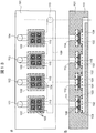
- FIG. 1 is a diagram illustrating a configuration of a flow cell device according to a first embodiment.
- 1 is a diagram illustrating a configuration of a two-dimensional array chip used in Embodiment 1.
- FIG. 2 is an enlarged view showing a unit structure of a two-dimensional array chip used in Example 1.
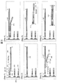
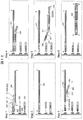
- FIG. 3 is a diagram showing a reaction process executed in Example 1.
- FIG. 6 is a diagram illustrating a configuration of a flow cell device according to a second embodiment.
- FIG. 5 is a diagram illustrating a configuration of a two-dimensional array chip used in the second embodiment.
- FIG. 5 is an enlarged view showing a unit structure of a two-dimensional array chip used in Example 2.
- FIG. 4 is a diagram showing a reaction process executed in Example 2.
- FIG. 10 is a diagram illustrating a configuration of a flow cell device according to a third embodiment.
- FIG. 10 is a diagram illustrating another configuration of the flow cell device according to the third embodiment.
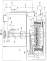
- FIG. 6 is a diagram illustrating a configuration example of a single cell analysis device used in Example 3.
- FIG. 6 is a diagram showing a configuration example of a single cell analysis apparatus used in Example 4.
- Two processes essential for single cell analysis can be performed in one flow cell device, avoiding manual reagent dispensing operations, reducing the volume of reagent required, and running required for single cell analysis Cost is reduced.
- the entire process of single-cell analysis can be automated (automated reaction processing required for each cell), which simplifies the sample preparation process required for large-scale sequencers. Single cell analysis will be possible.
- a flow cell device by applying a membrane device to which a cell identification sequence disclosed in Patent Document 3 is fixed for sample preparation from mRNA extracted from cells.
- a membrane device to which a cell identification sequence disclosed in Patent Document 3 is fixed for sample preparation from mRNA extracted from cells.
- a 1 st cDNA library with high efficiency from a large number of cells simultaneously, at the same time, it is possible to achieve a uniform sample preparation with a small amount of reagent per cell. That is, a sample for a large-scale sequence analyzer (next-generation sequencer) capable of gene expression analysis for each individual cell can be prepared.
- a sequencing library can be constructed at a low cost.
- a method that can be processed using a cell identification tag of a type that is significantly smaller than the number of cells in the flow cell device in the sample preparation reaction of the flow cell device will also be described.
- a plurality placed a membrane device with a cell identification tags of the same combination in the flow-cell device (a membrane device with for example 100 different identification tag placed in 20 sheets of the flow cell devices), 2 nd cDNA synthesis
- a tag sequence that can identify different membrane devices during subsequent reactions is inserted into a nucleic acid sample for sequencing.
- the number of cells that can be processed by one flow cell device is a number given by the product of the number of types of cell identification tags on one membrane device and the number of types of tag arrays for identifying membrane devices. Can be increased. In other words, by preparing an array of types given by the sum of the number of types of cell identification tags and the number of types of tag arrays for identifying membrane devices, cells given by the product of the number of these tags are prepared. Identification up to a number is possible. By realizing this method on the flow cell device according to the embodiment, the reagent amount per cell can be reduced and the reagent cost can be reduced.
- each of the reaction chambers has at least one pair of a cell capture unit and a nucleic acid capture unit, and (2) the common connection to the plurality of reaction chambers.
- a single cell analysis flow cell device having a third liquid flow path for collecting the second liquid will be described.
- each of the plurality of reaction chambers having at least one pair of a cell capturing unit and a nucleic acid capturing unit, and (2) a pair of the plurality of reaction chambers.
- a plurality of first liquid channels that are individually connected to each of the reaction chambers, and (3) a common connection to the plurality of reaction chambers, and the cell capture unit and the nucleic acid capture unit.
- a flow cell device for single cell analysis having a second liquid flow path for collecting the liquid that has passed through the section will be described.
- FIG. 1 shows a top view (FIG. 1 (a)) and a cross-sectional view (FIG. 1 (b)) of a flow cell device.
- the flow cell device 101 is provided with a plurality of reaction chambers 102.
- one or a plurality of cell capture units 103 and one or a plurality of nucleic acid capture units 104 are arranged in each reaction chamber 102.
- the nucleic acid capture unit 104 is desirably arranged in one-to-one correspondence with the cell capture unit 103. By being one-to-one, the correspondence between one cell captured by the cell capturing unit 103 and the nucleic acid captured by the nucleic acid capturing unit 104 becomes clear. In the case of FIG.
- the nucleic acid capturing unit 104 is stacked on the lower surface side of the cell capturing unit 103. Due to the stacked relationship, the nucleic acid extracted from one cell captured by the cell capturing unit 103 can be reliably introduced into the corresponding nucleic acid capturing unit 104.
- a flow cell device 101 shown in FIG. 1 includes a plurality of reaction chambers 102 in a substrate and a common supply channel 105 connected on the upper surface side, and a plurality of reaction chambers 102 and a common suction channel connected on the lower surface side. 109.
- a solution containing cells 106 to be examined flows through the common supply channel 105.
- the solution is introduced from an upper common inlet 107 provided in the common supply flow path 105, flows along the common supply flow path 105, and is recovered from the upper common outlet. At this time, the solution fills each reaction chamber 102 located on the common supply channel 105.
- a negative pressure is applied to the lower common outlet 110 provided in the common suction channel 109. Since the common suction channel 109 has a negative pressure, a part of the solution filling the reaction chamber 102 flows into the common suction channel 109 through the cell capturing unit 103 and the nucleic acid capturing unit 104.
- the cell trap 103 is configured with an opening smaller than the diameter of the cell 106. Therefore, the cell 106 is captured by the opening of the cell capturing unit 103.
- a nucleic acid trap 104 made of a porous material is disposed immediately below the cell trap 103.
- the fine figure 10 vesicle capturing part 103 and the nucleic acid capturing part 104 are produced on a two-dimensional array chip 115 arranged one-on-one with respect to the reaction chamber 102.
- a two-dimensional array chip 115 arranged one-on-one with respect to the reaction chamber 102.
- four structures in a single reaction chamber 102 are arranged at predetermined positions in the reaction chamber 102.
- the cells 106 are uniformly captured by the plurality of cell traps 103 on the plurality of two-dimensional array chips 115 arranged in the plurality of reaction chambers 102.
- a separate fluid flow path is connected to each reaction chamber 102 in addition to the common supply flow path 105 so that the captured cells 106 can be processed differently for each reaction chamber 102.
- the fluid flow paths are connected to the reaction chamber 102 on a one-to-one basis.
- FIG. 1 four fluid flow paths and their corresponding four individual inlets 111, 112, 113, 114 are shown.
- individual reagents are introduced according to the processing content to be executed in the connected reaction chamber 102.
- individual fluid flow paths are connected from the side of the upper surface side of each reaction chamber 102.
- water repellent inside wall surfaces of the regions 116 between the reaction chambers 102 or before and after each reaction chamber 102
- a non-polar solvent such as mineral oil may be flowed from the upper common inlet 107 to the upper common outlet 108 prior to the introduction of the individual reagents, using a common supply channel 105 that has been treated with (hydrophobic).
- the nonpolar solvent remains in the region 116 in the common supply channel 105, and the reaction chambers 102 are separated from each other. That is, the aqueous solution that is a polar solvent cannot pass through the region 116, and the individually introduced reagent is not introduced into the other reaction chamber 102.
- a common solution can be introduced into a plurality of reaction chambers 102 through the common supply channel 105 at a time, and individual reactions can be performed through the individual fluid channels. Individual reagents can be introduced into chamber 102. For this reason, the use of the flow cell device 101 shown in FIG. 1 makes it possible to simultaneously perform highly accurate gene expression analysis for a large number of cells.
- reaction processes that do not require the introduction of individual reagents (reaction solutions)
- the same reaction process can be executed in multiple reaction chambers 102, making the reactions uniform in each reaction chamber 102 and achieving high-precision analysis. Is done.
- the flow cell device 101 (FIG. 1) is provided with a plurality of reaction chambers 102, and each reaction chamber 102 isolates and captures individual cells from a plurality of cells. And a two-dimensional array chip 115 in which a plurality of structures, each of which includes a nucleic acid capturing unit 104 made of a porous material, are arranged in a plane.
- FIG. 2 shows an enlarged structure of the inner wall surface (the surface of the porous material) of the nucleic acid capturing unit 104.
- the first DNA probe 201 is fixed to the inner wall surface of the nucleic acid capturing unit 104.
- This first DNA probe 201 is a known sequence for identifying a cell 106 from a capture sequence (poly T) 202 for capturing a nucleic acid (mRNA) 206 extracted from a cell captured by the cell capture unit 103.
- a sequence (cell identification sequence) 203 and a common sequence 204 for PCR amplification are included.
- Step 1 This step shows that mRNA 206 is captured by the capture sequence 202 of the first DNA probe 201. Even in the case of the nucleic acid capturing unit 104 in the same reaction chamber 102, different cell identification sequences 203 are attached if the positions in the reaction chamber 102 are different. For example, in the case of the structure of FIG. 1, the four nucleic acid capturing units 104 constituting the two-dimensional array chip 115 are given unique cell identification sequences 203 corresponding to the respective arrangement positions. The nucleic acid 206 is taken out from the cell 106 by crushing the cell 106 captured by the cell capturing unit 103 by electrophoresis or solution flow.
- Step 2 This step, the mRNA 206 that has captured the first DNA probe 201 as a template, and illustrates how to synthesize 1 st cDNA strand 207.
- the reverse transcriptase and the substrate necessary for this synthesis reaction are supplied by the following procedure. First, a buffer solution containing an enzyme and a substrate is flowed from the upper common inlet 107 toward the upper common outlet 108, and the upper space of the two-dimensional array chip 115 in each reaction chamber 102 is filled with this buffer solution. Next, a negative pressure is applied to the lower common outlet 110, and the solution in the reaction chamber 102 is caused to flow through the common suction channel 109 so as to pass through the nucleic acid capturing unit 104. Fulfill.
- Step 3 the second DNA probe 208 that hybridizes from the cell identification sequence 203 to a predetermined position / range (for example, around 200 bases / range of 150 to 250 bases) is independently introduced into each reaction chamber 102.
- Step 3 in FIG. 2 shows that the second DNA probe 208 is hybridized to the 1 st cDNA strand 207.
- the second DNA probe 208 is composed of a common primer (Forward) 209 for PCR from the 5 ′ end, a chip identification sequence 210, and a gene-specific probe 211 that is a sequence complementary to the 1 st cDNA strand 207. ing.
- the chip identification array 210 has a different array for each reaction chamber 102 (that is, for each two-dimensional array chip 115). Further, the gene-specific probes 211 are required as many as the number of gene expression data to be acquired. When 20 types of gene expression analysis are performed, a mixed solution of 20 types of gene-specific probes 211 is introduced into the reaction chamber 102.
- the introduction of the second DNA probe 208 into the reaction chamber 102 is performed according to the following procedure.
- mineral oil is introduced from the upper common inlet 107 and discharged from the upper common outlet 108 on the opposite side through the common supply channel 105.
- the four reaction chambers 102 connected to the common supply channel 105 have not been separated yet.
- a salt-containing buffer solution is allowed to flow from the common suction channel 109 toward the individual inlets 111, 112, 113, 114, and excess mineral oil in the individual reaction chambers 102 is separated from the individual inlets 111, 112, It discharges through 113,114. After this drainage, the mineral oil remains only in region 116.
- the four reaction chambers 102 connected to the common supply channel 105 are separated from each other. That is, the upper space of the two-dimensional array chip 115 provided in the reaction chamber 102 is separated from the upper space of the two-dimensional array chip 115 provided in the other reaction chamber 102.
- Such separation occurs because the inner wall of the reaction chamber 102 that defines the upper space of the two-dimensional array chip 115 is surface-treated so as to be hydrophilic, whereas the region located between the reaction chambers 102 This is because the surface treatment is performed so that 116 becomes hydrophobic. It is also important to maintain high reaction efficiency that the 1 st cDNA probe 201 is firmly fixed to the inner wall surface (the surface of the porous material) of the nucleic acid capturing unit 104 (for example, by a biotin-avidin bond).
- a buffer solution containing the second DNA probe 208 having a different chip identification sequence 210 is introduced into the reaction chamber 102 through the individual inlets 111, 112, 113, 114, and the introduced buffer solution Is discharged from the lower common outlet 110 via the cell trapping part 103, the nucleic acid trapping part 104, and the common suction channel 109.
- the vicinity of the inner wall of the nucleic acid trap 104 is filled with the second DNA probe 208 that is different for each reaction chamber 102, and the second DNA probe 208 is hybridized to the 1 st cDNA strand 207.
- Step 4 to synthesize 2 nd cDNA 212.
- a large amount of buffer solution is flowed from the upper common inlet 107 toward the upper common outlet 108.
- a large amount of buffer solution will wash away the emulsion oil that has remained in region 116. Since the purpose of flowing a large amount of buffer solution through the common supply channel 105 is to reconnect the common supply channel 105, some emulsion oil may remain in the region 116.
- the enzyme and the substrate necessary for the 2 nd cDNA synthesis is introduced into the reaction chamber 102.
- Steps 5 and 6 In these steps, PCR amplification with the common primer 214 is performed.
- the PCR common primer necessary for amplification (Forward) 214, a common primer (Reverse) 213, and PCR enzyme, a substrate is introduced into the reaction chamber 102 at 1 st case the same procedure cDNA strand 207.
- the PCR product 215 obtained after completion of the reaction is a sequence that can be sequence-analyzed (more precisely, a sequence that can be pre-processed for sequence analysis (emulsion PCR or the like)), and is called a sequencing library.
- the gene expression level can be obtained for each cell identification sequence (cell identification sequence 203) and chip identification sequence (chip identification sequence 210). That is, it is possible to simultaneously analyze the number of cells equal to or less than the product of the type of the cell identification sequence 203 and the type of the chip identification sequence 210 introduced into the flow cell device 101 at the same time. As a result, it becomes possible to analyze the number of cells significantly larger than the number of cell identification sequences introduced into the two-dimensional array chip 115 in advance.
- the second method instead of introducing the chip identification sequence 210 when synthesizing the 2 nd cDNA 212, introducing a chip identification sequence in the first process of PCR amplification after 2 nd cDNA synthesis.
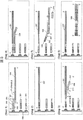
- FIG. 3 shows the entire process up to obtaining a sequencing library, similar to FIG.
- Steps 1 and 2 The sequence of the first DNA probe 301 immobilized on the inner wall surface of the nucleic acid capturing unit 104 is provided with a common connection sequence 302 instead of the common sequence 204 (common PCR primer (Reverse)).
- Step 3 The second DNA probes 303 during 2 nd cDNA synthesis is the sequence excluding the chip identification sequence 210 from the second DNA probe 208 (FIG. 2). That is, the second DNA probe 303 is composed of only a common primer (Forward) 209 and a gene-specific probe 211.
- Step 4 Wherein the second DNA probe 303 hybridizes to the 1 st cDNA strand 207 to synthesize 2 nd cDNA strands 304.
- Step 5 Respect synthesized 2 nd cDNA strands 304, are hybridized third DNA probe 305 having a second chip identifier sequence 307.
- the third DNA probe 305 includes a PCR common primer (Reverse) 306, a second chip identification sequence 307, and a complementary sequence 308 of the common connection sequence.
- Step 6 A sequencing library is constructed as a PCR amplification product 309 obtained after completion of the PCR process. Since the number of types of the third DNA probe 305 may be the same as the number of chips, the initial cost for the DNA probe can be reduced and the number of simultaneously analyzed cells can be increased.
- the nucleic acid capturing unit 104 is configured by packing a large number of beads having DNA (DNA probes) for capturing a nucleic acid immobilized on the surface.
- the sequencing library is adjusted based on the first method described above.
- FIG. 4 shows a top view (FIG. 4 (a)) and a cross-sectional view (FIG. 4 (b)) of the flow cell device 101 used in this embodiment.
- the basic structure of the flow cell device 101 in the present embodiment is the same as the basic structure of FIG. That is, the flow cell device 101 has four reaction chambers 102, and each reaction chamber 102 has one or a plurality of cell capture units 103 and nucleic acid capture units 104.
- the nucleic acid capture unit 104 is desirably arranged in a one-to-one relationship with the cell capture unit 103. In FIG. 4, the nucleic acid capture units 104 are arranged one-on-one with respect to 7 ⁇ 7 cell capture units 103 formed on the two-dimensional array chip 115.
- the nucleic acid capturing unit 104 is disposed immediately below the cell capturing unit 103.
- the nucleic acid capturing unit 104 is formed by a space filled with a large number of magnetic beads.
- a solution containing the cells 106 is introduced from the common inlet 107. The introduced solution sequentially flows into the four reaction chambers 102 along the common supply channel 105 and is finally discharged from the upper common outlet 108.
- a part of the solution in the common supply channel 105 passes through the reaction chamber 102 by controlling the common suction channel 109 formed in the lower part of the reaction chamber 102 to a negative pressure. It flows to the common suction channel 109.
- a cDNA library is constructed in the nucleic acid capture unit 104 formed at the same position as the cell capture unit 103. This library is used as a template for synthesis of the 2 nd cDNA using a DNA probe having a different sequence for each two-dimensional array chip 115, to construct a sequencing library.
- FIG. 5 shows a detailed configuration of the two-dimensional array chip 115 used in this embodiment.
- FIG. 5A is a cross-sectional view cut perpendicularly to the surface of the two-dimensional array chip 115.
- 5B is a cross-sectional view of the AA ′ cross section of FIG. 5A viewed from the upper surface side
- FIG. 5C is the BB ′ cross section of FIG. 5A of the upper surface side. It is sectional drawing seen from.
- the cell trapping part 103 corresponds to each opening (channel 504) formed on the upper surface side of the chip 503, and the nucleic acid trapping part 104 is accommodated in a space surrounded by the chip 503 and the pore array sheet 502. It corresponds to a large number of magnetic beads 601.
- FIG. 6 shows an enlarged unit structure of the two-dimensional array chip 115 (FIG. 5).
- the unit structure is composed of a pair of cell traps 103, a nucleic acid trap 104 packed with a large number of magnetic beads 601, and a pore array sheet 502 in which a lower channel 501 is formed.
- the pore array sheet 502 functions as a member that closes a large number of concave portions formed on the lower surface side of the chip 503 and confines the magnetic beads 601 in the concave portions.
- the lower channel 501 is a large number of through holes formed in the pore array sheet 502, and connects the nucleic acid capturing unit 104 and the common suction channel 109.
- the size of the lower flow path 501 is formed such that the magnetic beads 601 can be held in the nucleic acid capturing unit 104.
- FIG. 7 shows known information necessary for capturing nucleic acid (mRNA) extracted from the cells 106 captured by the cell capturing unit 103 (step 1), cDNA synthesis (step 2), nucleic acid amplification (PCR), and sequencing.
- mRNA nucleic acid
- step 3 and 4 The conceptual diagram of the step of the synthesis
- step 3 and 4 The conceptual diagram of the step of the synthesis
- Step 1 First, the cells 106 were washed with 500 ⁇ L of 1 ⁇ PBS buffer (Phosphate buffered saline) without damaging them, and then 1000 cells 106 suspended in 10 ⁇ L of 1 ⁇ PBS buffer cooled to 4 ° C. were flow cells. It is introduced from a common inlet 107 formed on the upper surface of the device 101 (FIG. 4). At the same time, the solution is sucked from the upper common outlet 108 which is the opposite end of the common supply channel 105 so that the four reaction chambers 102 are filled with this solution. Thereby, the upper part of the two-dimensional array chip 115 arranged in each reaction chamber 102 is filled with the PBS buffer containing the cells 106.
- 1 ⁇ PBS buffer Phosphate buffered saline
- a negative pressure (1.0 atm) is applied to the lower common outlet 110, and the solution is sucked from the cell trap 103 into the common suction channel 109 (FIG. 4).
- the cell 106 moves along the flow of the solution and reaches the cell trap 103.
- the opening diameter of the cell trapping portion 103 is smaller than the diameter of the cell 106, the reached cell 106 is trapped in the opening of the cell trapping portion 103. Since the trapped cells 106 serve as plugs for the solution flow, the solution flow moves to the cell trapping portion 103 that has not yet captured the cells 106. Therefore, the remaining cells 106 in the solution move to the openings that have not yet captured the cells 106 and are captured.
- the cells 106 remaining in the reaction chamber 102 (excess cells 106 that have not been trapped) and the PBS buffer are discharged from the upper common outlet 108.
- a cell lysis solution (Lysis buffer) (for example, a surface active agent such as Tween 20) is allowed to flow from the upper common inlet 107 toward the upper common outlet 108 to fill the reaction chamber 102 with the cell lysis solution.
- a negative pressure is applied to the lower common outlet 110 to aspirate the cell lysate.
- the lower flow path 501 formed in the pore array sheet 502 is a flow path made of a porous material having a diameter of 0.2 ⁇ m and has a large pressure loss. For this reason, the cell lysate continues to flow slowly from the reaction chamber 102 through the cell capture unit 103 and the nucleic acid capture unit 104 to the common suction channel 109 over a period of about 5 minutes.
- the cell lysate breaks the cells 106 while flowing.
- Nucleic acid (mRNA) 206 is extracted from the disrupted cells 106.
- the nucleic acid 206 passes through the cell capture unit 103 together with the cell lysate without reaching the periphery, and reaches the nucleic acid capture unit 104.
- an electric field may be applied in the direction indicated by the arrow 603 (the direction from the lower surface side to the upper surface side of the flow cell device 101) to move the nucleic acid 206 in the cell 106 to the nucleic acid trap 104 by electrophoresis.
- Position information on the two-dimensional array chip 115 of the cell capture unit 103 that has captured the cell 106 (in the case of FIG. 5A, the cell capture at any position of the cell capture units 103 arranged in a 7 ⁇ 7 lattice pattern)
- the information on the part 103) is stored as the sequence information of the first DNA probe 201 fixed to the magnetic bead 601 of the corresponding nucleic acid capturing part 104. That is, a different capture sequence 202 is introduced into the first DNA probe 201 of the nucleic acid capture unit 104 for each position of the nucleic acid capture unit 104 on the two-dimensional array chip 115.
- the first DNA probe 201 has a poly T sequence at the 3 ′ end in addition to the capture sequence 202.
- the nucleic acid 206 is captured by hybridizing the poly T sequence at the 3 ′ end on the first DNA probe 201 side with the poly A sequence at the 3 ′ end of the nucleic acid 206.
- a common primer 204 reverse for PCR amplification is further provided on the 5 ′ end side of the first DNA probe 201.
- the first DNA probe 201 of the present example has a slightly more complicated sequence configuration, 30 base PCR amplification common primer 204 (Reverse) from the 5 ′ end, 7 base cell recognition sequence and 7 bases.
- 30 base PCR amplification common primer 204 reverse
- 7 base cell recognition sequence 7 bases.
- a cell identification sequence 203 consisting of a random sequence
- 18 base oligo (dT) sequence + a capture sequence 202 consisting of a 2 base VN sequence.
- a sequence for molecular recognition for example, 7 bases
- 4 7 1.6 ⁇ 10 4 molecules can be recognized, so the DNA sequence for the amplification product obtained by the next-generation sequencer From the data, it is possible to recognize which molecule is derived from the amplification product having the same gene sequence from the same cell.
- the amplification bias between genes generated in the amplification process can be corrected.
- the amount of nucleic acid initially present in the sample can be quantified with high accuracy.
- the accuracy of amplification bias correction decreases.
- the oligo (dT) sequence located most 3 ′ is hybridized with the poly A tail added to the 3 ′ side of the nucleic acid 206 and used to capture the nucleic acid 206.
- a poly-T sequence was used as a part of the first DNA probe 201 to analyze mRNA.
- a random sequence is replaced with a sequence to be analyzed. It goes without saying that a part of the complementary sequence may be used.
- Step 2 A 1 st cDNA strand is synthesized using the nucleic acid 206 captured by the first DNA probe 201 as a template.
- 5 mM of 10 mM Tris Buffer (pH 8.0) containing 0.1% Tween20 as the 1 st cDNA strand synthesis reagent, 4 ⁇ L of 10 mM dNTP, 225 ⁇ L of 5xRT Buffer (SuperScript III, Invitrogen), 4 ⁇ L of 0.1 M DTT, RNaseOUT (Invitrogen 4 ⁇ L and Superscript III (reverse transcriptase, Invitrogen) 4 ⁇ L are mixed and introduced from the upper common inlet 107 in the same manner as in the previous step.
- the solution is slowly raised to 50 ° C. while flowing very slowly from the reaction chamber 102 to the common suction channel 109 with the above solution filled in the gaps of the magnetic beads 601 packed with the solution containing reverse transcriptase and a synthetic substrate.
- the complementary strand synthesis reaction (1 st cDNA strand synthesis reaction) was carried out for about 50 minutes after heating.
- RNA is degraded, and the residue and degradation products in the nucleic acid capturing unit 104 are removed and washed. Further, it is washed five times in the same manner with a solution containing an alkali modifier and a washing solution.
- a cDNA library array for each captured cell is constructed.
- Steps 3 and 4 Next, 69 ⁇ L of sterilized water, 10 ⁇ L of 10 x Ex Taq Buffer (TaKaRa Bio), 100 ⁇ L of 2.5 mM dNTP Mix, and 10 ⁇ M of each PCR amplification consensus sequence (Reverse) were added to the Ex Taq Hot start version (TaKaRa Bio) 1 ⁇ L was mixed, and this mixed reagent was introduced from the upper common inlet 107 into the nucleic acid capturing unit 104 through the common supply channel 105 in the same manner as in the previous step. An individual introduction method of 10 ⁇ L of a mixed solution of 20 kinds of second DNA probes 208 with chip identification tags will be described later.
- FIG. 7 shows a state in which the second DNA probe 208 is hybridized to the 1 st cDNA strand 207. Furthermore, 6 minutes, the temperature was raised to 72 ° C. perform complementary strand extension reaction, to synthesize the 2 nd cDNA strands 304.
- a mixed solution of 20 types of second DNA probes 208 having different sequences in the region of the gene-specific probe 211 (a solution having a different chip identification sequence for each reaction chamber 102 (that is, for each two-dimensional array chip 115)) It is introduced for each two-dimensional array chip 115 (reaction chamber 102). In this introduction, individual inlets 111, 112, 113, and 114 are used as described later.
- the number of gene-specific probes 211 required is the number for acquiring gene expression data.
- a mixed solution of 200 types of gene-specific probes 211 is introduced into the reaction chamber 102.
- the porous inner wall, 1 st cDNA strand 207 firmly - it is important that the (eg, biotin by avidin binding) fixed.
- a buffer solution containing the second DNA probe 208 having a different chip identification sequence is introduced from the individual inlets 111, 112, 113, 114, passed through the common suction channel 109, and the lower common outlet Drain from 110.
- the vicinity of the inner wall of the nucleic acid capturing unit 103 is filled with the second DNA probe 208 that is different for each reaction chamber 102, and this probe can hybridize to the 1 st cDNA strand 207.
- the chip identification tag in the second DNA probe 208 is a 4-base random sequence, which enables identification of a maximum of 256 chips.
- 20 gene-specific sequences for example, ATP5B, GAPDH, GUSB, HMBS, HPRT1, RPL4, RPLP1, RPS18, RPL13A, RPS20, ALDOA, B2M, EEF1G, SDHA, TBP, VIM, RPLP0, RPLP2, RPLP27 and 20 ⁇ 5 bases upstream of 109 ⁇ 8 bases from the poly A tail of the target gene were used for the gene-specific sequence of OAZ1). This is to unify the PCR product size to about 200 bases in the subsequent PCR amplification step.
- Steps 5 and 6 Finally, PCR amplification with common primers is performed.
- 49. ⁇ L of sterilized water 10 ⁇ L of 10 x High Fidelity PCR Buffer (Invitrogen), 10 ⁇ L of 2.5 mM dNTP mix, 4 ⁇ L of 50 mM MgSO 4 , 10 ⁇ L of 10 ⁇ M common primer for PCR amplification (Forward), 10 ⁇ M of 10 ⁇ M
- a reagent is prepared by mixing 10 ⁇ L of the common sequence primer for PCR amplification (Reverse) and 1.5 ⁇ L of Platinum Taq Polymerase High Fidelity (Invitrogen). Further, the solution filling the common suction channel 109 of the flow cell device 101 is discharged from the lower common outlet 110.
- the prepared reagent is introduced into the common supply channel 105 through the upper common inlet 107 as in the previous step.
- the entire flow cell device 101 is kept at 94 ° C. for 30 seconds, and thereafter, a three-stage process of 94 ° C. for 30 seconds ⁇ 55 ° C. for 30 seconds ⁇ 68 ° C. for 30 seconds is repeated 40 cycles.
- the entire flow cell device 101 is kept at 68 ° C. for 3 minutes, and then cooled to 4 ° C. to perform a PCR amplification step.
- This reaction is a common reaction. Therefore, PCR amplification is performed under common reagent conditions for all chips, and amplification efficiency between chips is made uniform.
- the obtained PCR product 215 is a sequence that can be sequence-analyzed (more precisely, a sequence that can be pre-processed for sequence analysis (emulsion PCR, etc.)), and is called a sequencing library.
- a sequencing library a sequence that can be pre-processed for sequence analysis (emulsion PCR, etc.)
- amplification bias occurs between genes or molecules in this process, it is possible to correct the amplification bias using molecular recognition tags after acquiring next-generation sequencing data. Data can be obtained.
- the gene expression level can be obtained for each cell identification sequence and chip identification sequence. That is, it is possible to simultaneously analyze the number of cells equal to or less than the product of the type of the cell identification sequence and the type of the chip identification sequence simultaneously introduced into the flow cell device. As a result, it is possible to analyze the number of cells significantly larger than the number of cell identification sequences previously introduced into the two-dimensional array chip.
- PCR amplification An example was described.
- the amplification method is not limited to PCR amplification, and other amplification methods such as rolling circle amplification (RCA), NASBA, and LAMP method may be used.
- the two-dimensional array chip 115 is manufactured as a chip 503 made of PDMS (polydimethylsiloxane).
- the chip 503 is formed with a cell trapping portion 103, a nucleic acid trapping portion 104 filled with magnetic beads 601, and a flow path 504 connecting them.
- the chip 503 includes a large number of concave structures corresponding to the cell trapping part 103 and a small-diameter channel 504 formed on the bottom surface (upper surface in the drawing). This structure is produced by injection molding.
- the flow paths 504 are through holes having a diameter of 10 ⁇ m, and are arranged in an array at intervals of 125 ⁇ m.
- the region on the upper surface side across the channel 504 corresponds to the cell capture unit 103, and the lower surface side (concave) across the channel 504 corresponds to the nucleic acid capture unit 104.
- the size of the chip 503 side is square 1.125 mm, the case of FIG. 5, the cell capturing unit 103 are located two 7 therein. This number is only an example, for example, it may be 10 two.
- the diameter of the cylindrical through hole forming the concave portion directly below the cell trapping portion 103 is 75 ⁇ m, and this portion is filled with magnetic beads 601 to form the nucleic acid trapping portion 104.
- a pore array sheet 502 in which a large number of pores are arranged in correspondence with the positions of the through holes (recesses) is disposed.
- the diameter of the pores of the pore array sheet 502 is set to 200 nm, which is smaller than 1 ⁇ m, which is the diameter of the magnetic beads 601.
- the magnetic beads 601 are filled using an ink jet printer head. That is, in a state where the upper and lower surfaces of the chip 503 are reversed, 2 nL of the solution of the magnetic beads 601 on which the first DNA probe 201 having a different arrangement for each region is fixed is placed in the space as the nucleic acid capturing unit 104. Fill. At this time, the magnetic bead 601 solution used for filling is suspended at a number density of 5 ⁇ 10 9 particles / mL of magnetic beads 601 having a diameter of 1 ⁇ m. Further, streptavidin is immobilized on the magnetic bead 601, and the first DNA probe 201 modified with the 5 ′ biotin group is immobilized via this streptavidin.
- the solvent is only the water in the bead solution due to capillary action because the inner wall of the pores in the pore array sheet 502 is a hydrophilic surface.
- the magnetic beads 601 remain in the nucleic acid capture unit 104 after absorption.
- the pore array sheet 502 various materials such as a monolith sheet composed of porous glass, a capillary plate obtained by bundling capillaries and sliced, a nylon membrane, and a gel thin film can be used. In this embodiment, alumina is anodized. The pore array sheet thus obtained was used. Such a pore array sheet 502 can be made by anodic oxidation, but a product having a pore diameter of 20 nm to 200 nm and a diameter of 25 mm is commercially available. In this embodiment, as described above, the pore array sheet 502 having a pore diameter of 200 nm is used. The pores in the pore array sheet 502 become the lower channel 501 connecting the nucleic acid capturing unit 104 and the lower common channel 109.
- the chip 503 is manufactured by PDMS, but a substrate made of a resin (polycarbonate, cyclic polyolefin, polypropylene) manufactured by nanoimprint technology or injection molding, a commercially available nylon mesh or a track etch membrane is used.
- the chip 503 may be used.
- thermal bonding can be used.
- the two-dimensional array chip 115 is configured by integrating the chip 503 and the pore array sheet 502.
- a separate reaction tube is prepared for each unique tag sequence, and the magnetic bead 601 and the DNA probe are included therein.
- the solution may be mixed in a Tris buffer (pH 7.4) containing 1.5 M NaCl and the binding reaction may be performed while rotating for 10 minutes.
- the pore array sheet 502 produced by the above-mentioned method can be used repeatedly, and for gene groups that need to know the expression level, a gene-specific sequence primer mix solution with a common sequence primer (Reverse) for PCR amplification added to produce, in the same manner as described above synthesis of 2 nd cDNA strands, PCR amplification, and emPCR subjected, it may be performed an analysis in the next generation sequencers. That is, by repeatedly using a cDNA library, it is possible to perform highly accurate expression distribution measurement for a necessary type of gene.
- the second adjustment method can also be executed using the above-described flow cell device 101 (FIGS. 5 and 6), and a sequencing library for the next-generation sequencer can be easily prepared.
- step 1 the sequence of the first DNA probe 301 (FIG. 3) immobilized on the inner wall of the nucleic acid capture unit 104 is a common connection sequence with a short base length of 10 bases instead of the common PCR primer (Reverse). It is only a point using 302.
- step 2 is exactly the same as the first adjustment method described above.
- the second DNA probe 303 to be used when the 2 nd cDNA strand synthesis is that it does not include chip identification sequence. That is, the mixed solution of 20 kinds of second DNA probes 303 is not introduced through the individual inlets 111, 112, 113, 114 for each two-dimensional array chip 115, but steps 1 and 2 of the first adjustment method. Similarly, a mixed solution of the second DNA probes 303 having the same arrangement for all the two-dimensional array chips 115 is introduced from the upper common inlet 107 through the common supply channel 105.
- step 4 as in the first adjustment method, it performs complementary strand extension reaction by raising the inter temperature of the whole of the flow cell devices 101 72 ° C. in 6 minutes, to synthesize the 2 nd cDNA strands.
- Step 5 with respect to the synthesized 2 nd cDNA strands 304, the third DNA probe 305 (the PCR common 306, a second chip identifier sequence 307 consists of complementary sequence 308.) hybridizing .
- the introduction method is exactly the same as the first adjustment method described above.
- the temperature of the entire flow cell device 101 is raised to 72 ° C. for 6 minutes to perform complementary strand extension reaction, thereby completing the introduction of the tag sequence.
- PCR amplification is performed by the same method as the first adjustment method, and a sequencing library is constructed as the PCR amplification product 309.
- FIG. 8 shows a configuration example of a single cell analysis apparatus that can automatically execute the first adjustment method or the second adjustment method using the flow cell device 101 described above.
- This single cell analysis apparatus can execute the first adjustment method or the second adjustment method by automatic control, introduce a reagent into the flow cell device 101, and cause the reaction.
- FIG. 8 shows the configuration of a single cell analyzing apparatus with particular attention paid to the liquid feeding control system.
- the control computer 1309 of the single cell analysis apparatus appropriately controls the cell introduction control device 1311, the reagent introduction control device 1312, the stage control system 1313, the upper reagent discharge device 1314, the lower reagent discharge device 1315, and the temperature control system 1316.
- the cell introduction control device 1311 controls introduction of the cells 106 into the flow cell device 101 of cells.
- the reagent introduction controller 1312 introduces a cell lysate for disrupting the cells 106, introduces an enzyme reagent for cDNA synthesis or PCR amplification, introduces the second and third DNA probes, and separates the reaction chamber 102. Control the introduction of mineral oil and so on.
- the cell introduction control device 1311 and the reagent introduction control device 1312 are connected to the upper common inlet 107 through a common pipe.
- the stage control system 1313 controls the change of the observation field of view of the flow cell device 101 (XYZ position of the stage on which the flow cell device 101 is placed) for microscopic observation.
- the upper reagent discharging device 1314 controls the discharging of unnecessary reagents, cells, mineral oil for separating the reaction chamber 102, and the like.
- the upper reagent discharging device 1314 and the upper common outlet are connected by a dedicated pipe.
- the lower reagent discharging device 1315 includes (1) introduction of cells 106 into the two-dimensional array chip 115, (2) suction for introducing various enzyme reagents, second and third DNA probes, substrates, etc. Controls the discharge of the prepared nucleic acid amplification product.
- the lower reagent discharging device 1315 and the lower common outlet 110 are connected by a dedicated pipe.
- the temperature control system 1316 controls the temperature (reaction temperature) in the flow cell device 101.
- the cell introduction control device 1311 and the reagent introduction control device 1312 are a flow cell device for storing cells 106 and various reagents (enzyme reagents, substrates, second and third DNA probes, primers) stored at an appropriate temperature at an appropriate timing. 101 is introduced into the common supply flow path 105 or the individual inlets 111, 112, 113, 114. For this reason, the cell introduction control device 1311 and the reagent introduction control device 1312 appropriately open and close the switching valve to switch the piping inside the device.
- the upper reagent discharging device 1314 and the lower reagent discharging device 1315 have a syringe pump or the like inside, and suck and discharge the reagent and the cell solution.
- the waste liquid accumulated in the syringe can be discharged into a waste liquid bottle or the like.
- the temperature control system 1316 has the ability to control the temperature of the reaction chamber 102 between 4 ° C. and 98 ° C., and is composed of a Peltier element and its control device.
- the stage control system 1313 will be described in a third embodiment.
- the single cell analysis apparatus shown in FIG. 8 executes the following series of controls using the control computer 1309.
- Step 1 the control computer 1309 executes a cell 106 capture process and a nucleic acid 206 capture process.
- the control computer 1309 controls the cell introduction control device 1311 to introduce a solution containing the cells 106 into the upper common inlet 107 from the solution tube.
- the control computer 1309 controls the upper reagent discharging device 1314 to temporarily fill the reaction chamber 102 with the cell solution.
- the control computer 1309 controls the lower reagent discharging device 1315 to capture the cells 106 on the two-dimensional array chip 115.
- the control computer 1309 sucks the cells 106 in the excessive cell solution by controlling the upper reagent discharging device 1314 and introduces the cell lysate from the upper common inlet 107.
- the control computer 1309 controls the lower reagent discharging device 1315, sucks the cell lysate through the common suction channel 109, and captures the nucleic acid (mRNA) 206 in the nucleic acid capturing unit 104.
- the control computer 1309 uses the temperature control system 1316 to control the temperature in the reaction chamber 102 to about 25 ° C. (the temperature at which mRNA capture occurs with high efficiency).
- Step 2 In order to synthesize the 1 st cDNA strand, the control computer 1309 introduces a cDNA synthesis reagent from the upper common inlet 107 using the reagent introduction controller 1312. Next, the control computer 1309 fills the reaction chamber 102 with the reagent using the upper reagent discharge device 1314, and then applies a negative pressure to the lower common outlet 110 using the lower reagent discharge device 1315. As a result, the cDNA synthesis reagent is introduced from the reaction chamber 102 into the two-dimensional array chip 115.
- the control computer 1309 uses the temperature control system 1316 to appropriately control the temperature of the flow cell device 101 for a certain reaction time, and the cDNA synthesis reaction is completed. Thereafter, the control computer 1309 uses the temperature control system 1316 to inactivate the cDNA synthase by heating the reaction chamber 102 to 85 ° C., and the RNase reagent is put on the two-dimensional array chip 115 as described above. Introduce.
- the control computer 1309 controls the reagent introduction controller 1312 to introduce the enzyme reagent solution into the upper common inlet 107.
- the reagent introduction control device 1312 and the upper common inlet 107 are connected by piping.
- the control computer 1309 introduces a buffer containing mineral oil and salt from the upper common inlet 107 and sucks it from the upper reagent discharging device 1314.
- the four reaction chambers 102 connected in series to the common supply channel 105 are separated from each other by the mineral oil.
- control computer 1309 connects the buffer solutions containing the second DNA probes 208 having different chip identification sequences to the corresponding individual inlets 111, 112, 113, 114 through the control of the reagent introduction controller 1312, Further, the lower reagent discharging device 1315 is controlled to introduce the DNA probe solution into the two-dimensional array chip 115.
- Steps 5 and 6 When the synthesis of 2 nd cDNA strands 304 is completed, the control computer 1309, together with the controls the reagent introduction control unit 1312 for introducing a washing buffer to the upper common inlet 107, the reaction chamber 102 and controls the upper reagent discharge device 1314 The mineral oil used for the separation is discharged from the region 116 of the common supply channel 105. Thereafter, the control computer 1309 introduces the common primer and the PCR amplification reagent into the upper common inlet 107, and introduces the reagent into the two-dimensional array chip 115 as in the above-described step. Thereafter, the control computer 1309 performs PCR amplification by applying a predetermined temperature cycle using the temperature control system 1316 for the PCR reaction.
- control computer 1309 introduces the second DNA probe 208 from the upper common inlet 107, and the third DNA probe 308 to the individual inlets 111, 112, 113, 114. Introduce from.
- Other operations are basically the same as those in the first adjustment method.
- the nucleic acid (mRNA) 206 contained in each cell 106 is used for constructing a cDNA library in a state where information on which cell in the cell group arranged in an array is derived is retained. Another method will be described.
- a pore array sheet having a DNA probe immobilized thereon is used as the nucleic acid capture unit 104 instead of the magnetic beads 601. By using the pore array sheet, it is possible to avoid the risk that the magnetic beads 601 are mixed between the nucleic acid capturing units 104 when the two-dimensional array chip 115 is set in the flow cell device 101.
- FIG. 9 shows the structure of the flow cell device 101 according to this embodiment
- FIG. 10 shows the structure of the two-dimensional array chip 115 used in this embodiment.
- FIG. 11 shows an enlarged cross-sectional view of the two-dimensional array chip 115
- FIG. 12 shows a reaction process for the second adjustment method.
- FIG. 10A is a cross-sectional view cut perpendicularly to the surface of the two-dimensional array chip 115.
- FIG. 10B is a cross-sectional view of the AA ′ cross section of FIG. 10A viewed from the upper surface side, and
- FIG. 10C is the BB ′ cross section of FIG. It is sectional drawing seen from.
- the pore array sheet constituting the nucleic acid capturing unit 104 through holes 1001 having a diameter of 0.3 ⁇ m were formed at a pitch of 0.5 ⁇ m in a SiO 2 film 1002 having a thickness of 5 ⁇ m.
- the first DNA probe 301 is fixed to the inner wall surface of the through hole 1001 serving as the nucleic acid capturing unit 104 using a silane coupling agent.
- the diameter (uppermost part) of the tapered concave part constituting the cell trapping part 103 is 10 ⁇ m.
- the cell trapping part 103 was prepared by forming an opening in a polyimide resin film 1003 having a thickness of 10 ⁇ m using lithography.
- borate buffer pH 10 containing 10 mM glycine, 0.01% SDS and 0.15 M NaCl in the volume of the device. 8.5
- 0.01% SDS heated to 60 ° C, which is 10 times the internal volume and 30 mM sodium citrate buffer (2xSSC, pH 7.0 containing 0.3M NaCl).
- 10mTris containing 0.1% Tween 20 of 100 times the internal volume is introduced and discharged to complete the washing.
- the reaction process is the same as in the first adjustment method 2 of Example 1.
- the common supply channel 105 (corresponding to the upper common inlet 107 and the upper common outlet 108) and the individual fluid channels (corresponding to the individual inlets 111, 112, 113, 114) are provided on the upper surface side.
- the flow cell device 101 having a structure in which the upper common inlet 107, the common supply channel 105, and the upper common outlet 108 are removed from the upper surface side of the flow cell device 101 (FIG. 1). Is used.
- the flow cell device 101 shown in FIG. 14 has an opening at the top of the two-dimensional array chip 115, so that the cell solution can be dropped directly on the top surface of the two-dimensional array chip 115 or can be observed with a microscope. ing.
- Other configurations are the same as those in FIG.
- the flow cell device 101 according to the present embodiment has a simpler structure than the flow cell device 101 according to the first and second embodiments.
- FIG. 15 shows a configuration example of a single cell analysis apparatus used in this example.
- the cell introduction control apparatus according to this example is replaced with the reagent introduction control apparatus 1312 for introducing an enzyme reagent or a DNA probe.
- a cell / reagent introduction control device 1317 having a function is provided, and introduction of the cell 106 and the reagent is realized through four individual inlets 111 to 114.
- the same solution is introduced into the four reaction chambers 102
- the same solution is introduced into the four individual inlets 111 to 114
- four individual inlets are introduced. Solutions corresponding to 111 to 114 are introduced.
- the reagent and the like introduced from the upper common inlet 107 in Examples 1 and 2 are introduced through the individual inlets 111 to 114.
- the composition and quantity of reagents and the like introduced in this example are the same as those in Examples 1 and 2.
- the reagent was introduced into the two-dimensional array chip 115 using the lower reagent discharging device 1315 after the reaction chamber 102 was filled with the solution with the upper reagent discharging device 1314.
- the reaction chamber 102 at the upper part of the two-dimensional array chip 115 is filled with the reagent, or an amount of reagent sufficient to cover the upper surface of the two-dimensional array chip 115 with the liquid is introduced from the individual inlets 111 to 114, and then the lower part.
- the reagent can be introduced into the two-dimensional array chip 115 by controlling the common suction channel 109 to a negative pressure using the reagent discharging device 1315.
- a cell capture position on a planar device such as the flow cell device 101 can be associated with a gene expression analysis result.
- a cell capture position on a planar device such as the flow cell device 101 (including a pore array sheet) can be associated with a gene expression analysis result.
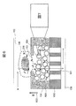
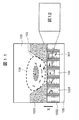
- FIG. 16 shows a configuration in which a single cell analyzer (FIG. 8) and an optical microscope are combined.
- FIG. 16 shows a situation where the cells 106 are captured on the two-dimensional array chip 115 of the flow cell device 101.
- the flow system 1201 corresponds to a single cell analyzer (FIG. 8), and performs extraction of nucleic acid (mRNA) 206 from the cell 106 and amplification thereof in the flow cell device 101, as in the above-described embodiment.
- An optical microscope 1203 is disposed above the flow system 1201. Arrow 1211 indicates the movement of the amplification product.
- the next generation (large-scale) DNA sequencer 1205 determines the sequence of the cells 106 based on the sequencing library as an amplification sample prepared by the flow cell device 101.
- the optical microscope 1203 includes a phase contrast microscope, a differential interference microscope, a fluorescence microscope, a laser-scanning confocal fluorescence microscope, a Raman microscope, a nonlinear Raman microscope (CARS microscope, SRS microscope, RIKE microscope), an IR microscope, and the like.
- the information obtained by these optical microscopes 1203 has little information as far as genetic information is concerned.
- the optical microscope 1203 can basically measure with the cells 106 alive. That is, it is possible to measure in real time changes over time of the cells 106, for example, the response of the cells to the stimulus.
- a device that stores position information on the flow cell device 101 detailed information related to gene expression can be associated with information including temporal changes by an optical microscope.
- the sequence information 1212 from the next generation (large-scale) DNA sequencer 1205, the information 1213 from the optical microscope image 1203, and the position information 1214 in which the tag sequence is associated are integrated.
- An information integration system 1206 is provided.
- the minimum configuration of the information integration system 1206 that integrates the measurement information of the cells 106 is a system 1207 other than the next-generation (large-scale) DNA sequencer 1205. It has the function of outputting the sample (nucleic acid amplification product).
- FIG. 16 shows a state where the cells 106 are captured on the pore array sheet constituting the flow cell device 101.
- a fluorescent substance is introduced into a specific protein in the cell 106 by expressing GFP in a protein to be measured (for example, p53) or by immunostaining. Data on the amount of expressed protein for individual cells 106 can be correlated with gene expression levels obtained by crushing cells 106, processing samples on a pore array sheet, and quantifying by DNA sequencing. it can.
- the nucleic acid is stained with DAPI and the cell nucleus is recognized, so that the cell position is identified by a fluorescence microscope.
- the information integration system 1206 executes the association between the fluorescence microscope data and the gene expression data and the estimation of information related to gene control.
- the fluorescence microscope includes a light source 1300, an excitation filter 1301, a dichroic mirror 1302, and an emission filter 1303.
- a light source 1300 for example, a mercury lamp is used.
- the excitation wavelength is determined by the excitation filter 1301.
- a light receiving wavelength is selected by the emission filter 1303.
- the control computer 1308 selects the excitation filter 1301, the dichroic mirror 1302, and the emission filter 1303 according to the control signal 1304, and only the light from the specific phosphors is selected. Measure.
- the fluorescence image of the cell 106 is acquired by the objective lens 1305, the imaging lens 1306, and the CCD camera 1307.
- the control computer 1308 controls these and acquires image data.
- control computer 1308 controls the XY stage 1310 to move the microscope image.
- control computer 1308 can associate the position coordinates on the pore array sheet, the array data of the cell recognition tag, and the position coordinates on the microscope image calculated from the position coordinates of the XY stage.
- the finally obtained nucleic acid amplification product is subjected to sequence analysis in a next-generation (large-scale) DNA sequencer 1205.
- emPCR and bridge amplifier for sequencing are executed in this system.
- the position information of the image and the cell recognition tag sequence information collated on the control computer 1308 are transmitted to the information integration system 1206, and the protein amount obtained from the fluorescence image is associated with the gene expression amount.
- the temporal change of gene expression analysis data is estimated. This makes it possible to measure the dynamics of the gene expression network.
- this fluorescence microscope may be used not only for intracellular measurement but also for measuring the amount of substances secreted from cells such as captured cytokines by immunofluorescence staining with antibodies. Of course, it may be similarly used for analysis of gene expression level after crushing.
- a differential interference microscope or a Raman microscope can be combined in place of the fluorescence microscope.
- the present invention is not limited to the above-described embodiments, and includes various modifications.
- the above-described embodiments have been described in detail for easy understanding of the present invention, and it is not necessary to provide all the configurations described.
- a part of one embodiment can be replaced with the configuration of another embodiment.
- the structure of another Example can also be added to the structure of a certain Example.
- a part of the configuration of another embodiment can be added, deleted, or replaced.
- each of the above-described configurations, functions, processing units, processing means, and the like may be realized by hardware by designing a part or all of them with, for example, an integrated circuit.
- Each of the above-described configurations, functions, and the like may be realized by the processor interpreting and executing a program that realizes each function (that is, in software).
- Information such as programs, tables, and files that realize each function can be stored in a storage device such as a memory, a hard disk, or an SSD (Solid State Drive), or a storage medium such as an IC card, an SD card, or a DVD.
- Control lines and information lines indicate what is considered necessary for the description, and do not represent all control lines and information lines necessary for the product. In practice, it can be considered that almost all components are connected to each other.
Landscapes
- Chemical & Material Sciences (AREA)
- Health & Medical Sciences (AREA)
- Life Sciences & Earth Sciences (AREA)
- Engineering & Computer Science (AREA)
- Genetics & Genomics (AREA)
- Organic Chemistry (AREA)
- Zoology (AREA)
- Wood Science & Technology (AREA)
- Bioinformatics & Cheminformatics (AREA)
- Biotechnology (AREA)
- General Health & Medical Sciences (AREA)
- General Engineering & Computer Science (AREA)
- Biomedical Technology (AREA)
- Physics & Mathematics (AREA)
- Analytical Chemistry (AREA)
- Proteomics, Peptides & Aminoacids (AREA)
- Microbiology (AREA)
- Biochemistry (AREA)
- Biophysics (AREA)
- Molecular Biology (AREA)
- Plant Pathology (AREA)
- Crystallography & Structural Chemistry (AREA)
- Clinical Laboratory Science (AREA)
- Chemical Kinetics & Catalysis (AREA)
- Hematology (AREA)
- Dispersion Chemistry (AREA)
- Bioinformatics & Computational Biology (AREA)
- Immunology (AREA)
- Fluid Mechanics (AREA)
- Evolutionary Biology (AREA)
- Medical Informatics (AREA)
- Spectroscopy & Molecular Physics (AREA)
- Medicinal Chemistry (AREA)
- Sustainable Development (AREA)
- Theoretical Computer Science (AREA)
- Apparatus Associated With Microorganisms And Enzymes (AREA)
Abstract
Description
具体的な形態例について説明する前に、各形態例で採用する基本構成や基本概念について説明する。各形態例では、単一細胞解析に必須の2つのプロセス(細胞の単離と、単離された個別の細胞からのサンプルの調製)を実行可能な構造を有するフローセルデバイスと当該フローセルデバイスを用いる単一細胞解析装置の処理動作について説明する。
図1に、フローセルデバイスの上面図(図1(a))と断面図(図1(b))を示す。フローセルデバイス101には複数の反応室102が設けられている。個々の反応室102には、1つ又は複数の細胞捕捉部103と1つ又は複数の核酸捕捉部104とが配置されている。核酸捕捉部104は、望ましくは、細胞捕捉部103に一対一に対応付けて配置されている。一対一であることで、細胞捕捉部103に捕捉された1つの細胞と、核酸捕捉部104に捕捉される核酸との対応関係が明確になる。図1の場合、核酸捕捉部104は、細胞捕捉部103の下面側に積層されている。積層関係にあることで、細胞捕捉部103に捕捉された1つの細胞から抽出された核酸を、対応する核酸捕捉部104に確実に導入することができる。
以下では、1回の配列解析において、多数の細胞からのシーケンシングライブラリを調整するための第1の方法について説明する。
このステップは、第1のDNAプローブ201の捕捉配列202に、mRNA 206が捕捉された様子を示している。なお、同じ反応室102内にある核酸捕捉部104であっても、反応室102内の位置が異なれば、異なる細胞識別配列203が付されている。例えば図1の構造の場合、2次元アレイチップ115を構成する4つの核酸捕捉部104には、各配置位置に応じた固有の細胞識別配列203が付されている。核酸206は、電気泳動又は溶液の流れによって、細胞捕捉部103に捕捉された細胞106を破砕することで細胞106から取り出される。
このステップは、第1のDNAプローブ201に捕捉したmRNA 206を鋳型として、1st cDNA鎖207を合成した様子を示している。この合成反応に必要となる逆転写酵素及び基質は、以下に示す手順で供給される。まず、酵素及び基質を含む緩衝溶液を、上部共通インレット107から上部共通アウトレット108に向かって流し、各反応室102内にある2次元アレイチップ115の上部空間をこの緩衝溶液で満たす。次に、下部共通アウトレット110に負圧を印加して、核酸捕捉部104を通過するように反応室102内の溶液を共通吸引流路109に流し、多孔質材料の表面近傍を必要な試薬で満たす。
このステップでは、細胞識別配列203から所定位置/範囲(例えば200塩基付近/150~250塩基の範囲)にハイブリダイズする第2のDNAプローブ208を反応室102毎に独立に導入する。図2のステップ3には、第2のDNAプローブ208が、1st cDNA鎖207にハイブリダイズしている様子を示している。第2のDNAプローブ208は、5'末端からPCR用の共通プライマー(Forward)209と、チップ識別配列210と、1st cDNA鎖207に相補的な配列である遺伝子特異的プローブ211とから構成されている。ここで、チップ識別配列210は、反応室102毎(すなわち、2次元アレイチップ115毎)に異なる配列をもつ。また、遺伝子特異的プローブ211は、遺伝子発現データを取得する数だけ必要であり、20種類の遺伝子発現解析を行う場合は20種類の遺伝子特異的プローブ211の混合溶液を反応室102に導入する。
このステップでは、2nd cDNA 212を合成する。この反応に必要な基質と酵素を導入するために、まず、上部共通インレット107から上部共通アウトレット108に向かって大量の緩衝溶液を流す。大量の緩衝溶液によって、領域116に留まっていたエマルジョンオイルが洗い流される。大量の緩衝溶液を共通供給流路105に流す目的は、共通供給流路105を再び繋げることであるため、多少のエマルジョンオイルが領域116に残っても良い。次に、1st cDNA合成の場合と同様のプロセスにより、2nd cDNA合成に必要な酵素と基質を反応室102に導入する。
これらのステップでは、共通プライマー214によるPCR増幅を行う。PCR増幅に必要な共通プライマー(Forward)214と、共通プライマー(Reverse)213と、PCR酵素と、基質とは、1st cDNA鎖207の場合と同様の手順で反応室102に導入される。反応完了後に得られたPCR産物215は、配列解析が可能な配列であり(正確には、配列解析の前処理(エマルジョンPCRなど)が可能な配列であり)、シーケンシングライブラリと呼ばれる。
ただし、前述の方法では、解析遺伝子数が多い場合、第2のDNAプローブ208の種類は、チップ識別配列210の種類数×解析遺伝子数で与えられる数だけ準備する必要がある。このため、多数の第2のDNAプローブ208を準備しなければならない。そこで、以下では、この問題を解決する第2の方法について説明する。
核酸捕捉部104の内壁表面に固定する第1のDNAプローブ301の配列は、共通配列204(共通PCRプライマー(Reverse))の代わりに共通接続配列302を設けている。
(ステップ3)
2nd cDNA合成時の第2のDNAプローブ303は、第2のDNAプローブ208(図2)からチップ識別配列210を除いた配列である。すなわち、第2のDNAプローブ303は、共通プライマー(Forward)209と遺伝子特異的プローブ211のみから構成されている。
前記第2のDNAプローブ303を1st cDNA鎖207にハイブリダイズして2nd cDNA鎖304を合成する。
(ステップ5)
合成された2nd cDNA鎖304に対して、第2のチップ識別配列307を持った第3のDNAプローブ305をハイブリダイズさせる。この第3のDNAプローブ305は、PCR共通プライマー(Reverse)306と、第2のチップ識別配列307と、共通接続配列の相補配列308とから構成されている。
PCRプロセス完了後に得られるPCR増幅産物309として、シーケンシングライブラリが構築される。第3のDNAプローブ305の種類の数は、チップの数と同じでよいため、DNAプローブのための初期コストを低減して、同時解析細胞数を増やすことができる。
(フローセルデバイスの構造)
以下では、前述の形態例の具体的な構成である実施例の1つを説明する。本実施例では、核酸捕捉のためのDNA(DNAプローブ)を表面に固定したビーズを多数パッキングして核酸捕捉部104を構成する。また、本実施例の場合、前述した第一の方法に基づいてシーケンシングライブラリを調整する。
図7を用いて、磁気ビーズ601の表面で実行される一連の処理を説明する。以下の処理は、前述の第1の調整方法に対応する。この図7には、細胞捕捉部103に捕捉された細胞106から抽出された核酸(mRNA)の捕捉(ステップ1)、cDNAの合成(ステップ2)、核酸増幅(PCR)およびシーケンスに必要な既知の末端配列を導入した2ndストランドの合成(ステップ3、4)、PCR増幅(ステップ5)のステップの概念図が示されている。図7のステップ1~6は、図3のステップ1~6に対応する。
まず、500μLの1×PBSバッファ(Phosphate buffered saline)で細胞106を傷つけないように洗浄した後、4℃に冷却された10μLの1×PBSバッファに懸濁された1000個の細胞106を、フローセルデバイス101(図4)の上面に形成された共通インレット107から導入する。同時に、4つの反応室102がこの溶液で満たされるように、共通供給流路105の反対側の端部である上部共通アウトレット108から当該溶液を吸引する。これにより、各反応室102に配置される2次元アレイチップ115の上部は、細胞106を含むPBSバッファで満たされる。
第1のDNAプローブ201に捕捉された核酸206を鋳型として、1st cDNA鎖を合成する。1st cDNA鎖合成試薬として0.1%Tween20を含む10mM Tris Buffer (pH=8.0) 58.5μLと、10mM dNTP 4μLと、5xRT Buffer (SuperScript III, Invitrogen社) 225μLと、0.1M DTT 4μLと、RNaseOUT (Invitrogen社) 4μLと、Superscript III(逆転写酵素, Invitrogen社) 4μLを混和し、上部共通インレット107から前工程と同様に導入する。上記溶液を逆転写酵素および合成基質を含む溶液でパックされた磁気ビーズ601の空隙部分を満たした状態で反応室102から共通吸引流路109に非常にゆっくり流しながら、溶液を50℃にゆっくり昇温して50分ほど相補鎖合成反応(1st cDNA鎖の合成反応)を行った。
次に、滅菌水69μLと、10 x Ex Taq Buffer (TaKaRa Bio社) 10μLと、2.5mM dNTP Mix 100μLと、各10μMのPCR増幅用共通配列(Reverse)が付加されたEx Taq Hot start version (TaKaRa Bio社)1μLとを混和し、この混合試薬を前工程と同様に上部共通インレット107から共通供給流路105を通じて核酸捕捉部104に導入した。チップ識別タグ付きの20種の第2のDNAプローブ208の混合溶液10μLの個別の導入方法については後述する。その後、95℃で3分間、核酸の2次構造を解き、その後、44℃で2分間、1st cDNA鎖207を鋳型としてプライマーの遺伝子特異的配列をアニールさせた。図7は、第2のDNAプローブ208が1st cDNA鎖207にハイブリダイズしている様子を示している。さらに、6分間、72℃に温度を上げて相補鎖伸長反応を行い、2nd cDNA鎖304を合成させる。
最後に、共通プライマーによるPCR増幅を実行する。まず、滅菌水49.μLと、10 x High Fidelity PCR Buffer (Invitrogen) 10μLと、2.5 mM dNTP mix 10μLと、50mM MgSO4 4μLと、10μMのPCR増幅用共通配列プライマー (Forward) 10μLと、10μMのPCR増幅用共通配列プライマー(Reverse) 10μLと、Platinum Taq Polymerase High Fidelity (Invitrogen社) 1.5μLとを混和して試薬を作製する。また、フローセルデバイス101の共通吸引流路109を満たしている溶液を下部共通アウトレット110から排出する。
ここでは、図5を用い、磁性ビーズ601を用いて構成される2次元アレイチップ115の構造と作製方法について説明する。2次元アレイチップ115は、PDMS(ポリジメチルシロキサン)製のチップ503として作製される。チップ503には、細胞捕捉部103、磁性ビーズ601を充填した核酸捕捉部104、これらを結ぶ流路504が形成される。なお、チップ503は、細胞捕捉部103に対応する多数の凹構造と、その底面(図中は上面)に形成された小口径の流路504とで構成される。この構造は、射出成型により作製される。流路504は、直径10μmの貫通孔であり、125μm間隔にアレイ状に配置される。流路504を挟んで上面側の領域が細胞捕捉部103であり、流路504を挟んで下面側(凹部)が核酸捕捉部104に対応する。
続いて、前述の第2の調整方法に対応する処理を説明する。第2の調整方法も、前述のフローセルデバイス101(図5、図6)を用いて実行でき、次世代シーケンサ用のシーケンシングライブラリを容易に調製することができる。
図8に、前述のフローセルデバイス101を用いて第1の調整方法又は第2の調整方法を自動的に実行することができる単一細胞解析装置の構成例を示す。この単一細胞解析装置は、第1の調整方法又は第2の調整方法を自動制御で実行し、フローセルデバイス101中に試薬を導入して反応させることができる。
このステップにおいて、制御コンピュータ1309は、細胞106の捕捉処理と核酸206の捕捉処理を実行する。まず、制御コンピュータ1309は、細胞導入制御装置1311を制御し、細胞106を含む溶液を溶液チューブから上部共通インレット107に導入する。次に、制御コンピュータ1309は、上部試薬排出装置1314を制御し、反応室102を細胞溶液で一旦満たす。続いて、制御コンピュータ1309は、下部試薬排出装置1315を制御し、2次元アレイチップ115上に細胞106を捕捉する。
1st cDNA鎖を合成するために、制御コンピュータ1309は、試薬導入制御装置1312を用いて、cDNA合成試薬を上部共通インレット107から導入する。次に、制御コンピュータ1309は、上部試薬排出装置1314を用いて反応室102を試薬で満たし、その後、下部試薬排出装置1315を用いて、下部共通アウトレット110に負圧を印加する。これにより、cDNA合成試薬が、反応室102から2次元アレイチップ115の内部に導入される。
制御コンピュータ1309は、試薬導入制御装置1312を制御して、酵素試薬溶液を上部共通インレット107に導入する。試薬導入制御装置1312と上部共通インレット107とは配管で接続されている。これにより、前記と同様、共通供給流路105に接続された各反応室102の各2次元アレイチップ115に上記試薬が導入される。次に、制御コンピュータ1309は、ミネラルオイル及び塩を含むバッファを上部共通インレット107から導入すると共に、上部試薬排出装置1314から吸引する。これにより、共通供給流路105に直列に接続された4つの反応室102がミネラルオイルによって互いに分離される。この後、制御コンピュータ1309は、試薬導入制御装置1312の制御を通じて、チップ識別配列の異なる第2のDNAプローブ208を含む緩衝溶液をそれぞれに対応する個別インレット111、112、113、114に接続し、更に下部試薬排出装置1315を制御して、2次元アレイチップ115内にDNAプローブ溶液を導入する。
2nd cDNA鎖304の合成が完了すると、制御コンピュータ1309は、試薬導入制御装置1312を制御して上部共通インレット107に洗浄バッファを導入すると共に、上部試薬排出装置1314を制御して反応室102の分離に用いたミネラルオイルを共通供給流路105の領域116から排出する。この後、制御コンピュータ1309は、共通プライマーとPCR増幅試薬を上部共通インレット107に導入し、前記工程と同様、試薬を2次元アレイチップ115内に導入する。その後、制御コンピュータ1309は、PCR反応のために、温度制御系1316を用いて所定の温度サイクルを印加してPCR増幅する。
本実施例では、個々の細胞106の中に含まれる核酸(mRNA)206が、アレイ状に配置された細胞群のどの細胞に由来するかの情報を保持した状態でcDNAライブラリを構築するための別の手法を説明する。本実施例では、核酸捕捉部104として、磁気ビーズ601の代わりに、DNAプローブを固定した細孔アレーシートを使用する。細孔アレーシートを用いることで、フローセルデバイス101に2次元アレイチップ115をセットするときに磁気ビーズ601が核酸捕捉部104の間に混じってしまうリスクを回避できる。
前述の実施例1及び2では、上面側に共通供給流路105(上部共通インレット107及び上部共通アウトレット108が対応)と個別の流体流路(個別インレット111、112、113、114が対応)が形成され、下面側に共通吸引流路109(下部共通アウトレット110が対応)が形成されているフローセルデバイス101を使用した。
2次元アレイチップ115を用いた遺伝子発現解析では、フローセルデバイス101(細孔アレーシートを含む)などの平面型デバイス上における細胞の捕捉位置と、遺伝子発現解析結果とを対応させることができる。例えば遺伝子発現解析のために細胞106を破砕して詳細な遺伝子発現解析を行う前に、細胞106が生きた状態での形状の取得、蛍光染色による遺伝子や蛋白質の定量、又はラマンイメージングの取得を実行し、これらのデータと遺伝子発現解析データとを対応させることができる。本実施例では、この機能を実現するためのシステム構成について説明する。
本発明は、上述した実施例に限定されるものでなく、様々な変形例を含んでいる。例えば、上述した実施例は、本発明を分かりやすく説明するために詳細に説明したものであり、必ずしも説明した全ての構成を備える必要はない。また、ある実施例の一部を他の実施例の構成に置き換えることができる。また、ある実施例の構成に他の実施例の構成を加えることもできる。また、各実施例の構成の一部について、他の実施例の構成の一部を追加、削除又は置換することもできる。
102 反応室
103 細胞捕捉部
104 核酸捕捉部
105 共通供給流路
106 細胞
107 上部共通インレット
108 上部共通アウトレット
109 共通吸引流路
110 下部共通アウトレット
111、112、113、114 個別インレット
115 2次元アレイチップ
116 領域
201 第1のDNAプローブ
202 捕捉配列
203 細胞識別配列
204 共通配列
206 核酸(mRNA)
207 1st cDNA鎖
208 第2のDNAプローブ
209 共通プライマー
210 チップ識別配列
211 遺伝子特異的プローブ
212 2nd cDNA
213、214 共通プライマー
215 PCR産物
301 第1のDNAプローブ
302 共通接続配列
303 第2のDNAプローブ
304 2nd cDNA鎖
305 第3のDNAプローブ
306 PCR共通プライマー
307 第2のチップ識別配列
308 相補配列
309 PCR増幅産物
501 下部流路
502 細孔アレーシート
503 チップ
601 磁気ビーズ
1001 貫通孔
1002 SiO2膜
1201 フローシステム
1203 光学顕微鏡
1205 次世代(大規模)DNAシーケンサ
1206 情報統合システム
1207 DNAシーケンサ1205以外のシステム
1212 配列情報
1213 情報
1214 位置情報
1300 光源
1301 励起フィルタ
1302 ダイクロイックミラー
1303 エミッションフィルタ
1304 制御信号
1305 対物レンズ
1306 結像レンズ
1307 CCDカメラ
1308 制御コンピュータ
1309 制御コンピュータ
1311 細胞導入制御装置
1312 試薬導入制御装置
1313 ステージ制御系
1314 上部試薬排出装置
1315 下部試薬排出装置
1316 温度制御系
1317 細胞/試薬導入制御装置
Claims (15)
- それぞれが、流路を通じて接続された少なくとも1つの細胞捕捉部と少なくとも1つの核酸捕捉部とを有する、複数の反応室と、
第1の面側において、前記複数の反応室に対して共通に接続される第1の液体流路と、
前記第1の面側において、前記複数の反応室に対して一対一に接続される複数の第2の液体流路と、
前記第1の面と対向する第2の面側において、前記複数の反応室に対して共通に接続される第3の液体流路と
を有する単一細胞解析用フローセルデバイス。 - 請求項1に記載の単一細胞解析用フローセルデバイスにおいて、
前記細胞捕捉部と前記核酸捕捉部は一対一に対応付けられている
ことを特徴とする単一細胞解析用フローセルデバイス。 - 請求項1に記載の単一細胞解析用フローセルデバイスにおいて、
前記細胞捕捉部は前記第1の面側に配置され、前記核酸捕捉部は前記第2の面側に配置される
ことを特徴とする単一細胞解析用フローセルデバイス。 - 請求項1に記載の単一細胞解析用フローセルデバイスにおいて、
前記核酸捕捉部は、多孔質構造又は多数のビーズをパックした構造である
ことを特徴とする単一細胞解析用フローセルデバイス。 - 請求項1に記載の単一細胞解析用フローセルデバイスにおいて、
前記核酸捕捉部のDNAプローブには、前記核酸捕捉部の配置位置を識別するための配列と、核酸を捕捉するための捕捉配列とが含まれる
ことを特徴とする単一細胞解析用フローセルデバイス。 - 請求項1に記載の単一細胞解析用フローセルデバイスにおいて、
前記複数の反応室の内壁はいずれも親水処理されており、前記複数の反応室を接続する前記第1の液体流路の内壁面は疎水処理されている
ことを特徴とする単一細胞解析用フローセルデバイス。 - それぞれが、流路を通じて接続された少なくとも1つの細胞捕捉部と少なくとも1つの核酸捕捉部とを有する、複数の反応室と、
第1の面側において、前記複数の反応室に対して一対一に接続される複数の第1の液体流路と、
前記第1の面と対向する第2の面側において、前記複数の反応室に対して共通に接続される第2の液体流路と
を有する単一細胞解析用フローセルデバイス。 - 請求項7に記載の単一細胞解析用フローセルデバイスにおいて、
前記細胞捕捉部と前記核酸捕捉部は一対一に対応付けられている
ことを特徴とする単一細胞解析用フローセルデバイス。 - 請求項7に記載の単一細胞解析用フローセルデバイスにおいて、
前記細胞捕捉部は前記第1の面側に配置され、前記核酸捕捉部は前記第2の面側に配置される
ことを特徴とする単一細胞解析用フローセルデバイス。 - 請求項7に記載の単一細胞解析用フローセルデバイスにおいて、
前記核酸捕捉部は、多孔質構造又は多数のビーズをパックした構造である
ことを特徴とする単一細胞解析用フローセルデバイス。 - 請求項7に記載の単一細胞解析用フローセルデバイスにおいて、
前記核酸捕捉部のDNAプローブには、前記核酸捕捉部の配置位置を識別するための配列と、核酸を捕捉するための捕捉配列とが含まれる
ことを特徴とする単一細胞解析用フローセルデバイス。 - 請求項7に記載の単一細胞解析用フローセルデバイスにおいて、
前記第1の液体流路は、前記細胞捕捉部を外部に露出させる前記反応室の開口として形成される
ことを特徴とする単一細胞解析用フローセルデバイス。 - それぞれが、流路を通じて接続された少なくとも1つの細胞捕捉部と少なくとも1つの核酸捕捉部とを有する複数の反応室と、第1の面側において、前記複数の反応室に対して一対一に接続される複数の第1の液体流路と、前記第1の面と対向する第2の面側において、前記複数の反応室に対して共通に接続される第2の液体流路とを有する単一細胞解析用フローセルデバイスが載置されるステージと、
前記ステージの位置を制御するステージ制御系と、
前記複数の第1の流体流路に対する第1の液体の導入を個別に制御する導入制御装置と、
前記第2の流体流路からの第2の液体の排出を制御する排出制御装置と
を有する単一細胞解析装置。 - 請求項13に記載の単一細胞解析装置において、
前記単一細胞解析用フローセルデバイスが有する、前記第1の面側において、前記複数の反応室に対して共通に接続される第3の液体流路に対して第3の液体を導入する第2の導入制御装置と、
前記第3の液体を前記第3の液体流路から排出する第2の排出制御装置と
を更に有することを特徴とする単一細胞解析装置。 - 請求項13に記載の単一細胞解析装置において、
前記単一細胞解析用フローセルデバイスを観察し、観察領域から取得された情報を前記ステージ制御系より取得した位置情報に対応付ける光学顕微鏡と、
前記単一細胞解析用フローセルデバイスの前記核酸捕捉部毎に得られた核酸増幅産物の配列を解析し、解析結果を前記ステージ制御系より取得した位置情報に対応付けるDNAシーケンサと、
前記光学顕微鏡が観察領域から取得した前記情報と、前記DNAシーケンサが取得した前記核酸捕捉部毎の解析結果とを統合する情報統合システムと
を更に有することを特徴とする単一細胞解析装置。
Priority Applications (3)
| Application Number | Priority Date | Filing Date | Title |
|---|---|---|---|
| PCT/JP2015/052965 WO2016125251A1 (ja) | 2015-02-03 | 2015-02-03 | 単一細胞解析用フローセルデバイス及び単一細胞解析装置 |
| US15/544,888 US10646869B2 (en) | 2015-02-03 | 2015-02-03 | Flow cell device for single cell analysis, and single cell analysis device |
| JP2016572977A JP6307179B2 (ja) | 2015-02-03 | 2015-02-03 | 単一細胞解析用フローセルデバイス及び単一細胞解析装置 |
Applications Claiming Priority (1)
| Application Number | Priority Date | Filing Date | Title |
|---|---|---|---|
| PCT/JP2015/052965 WO2016125251A1 (ja) | 2015-02-03 | 2015-02-03 | 単一細胞解析用フローセルデバイス及び単一細胞解析装置 |
Publications (1)
| Publication Number | Publication Date |
|---|---|
| WO2016125251A1 true WO2016125251A1 (ja) | 2016-08-11 |
Family
ID=56563616
Family Applications (1)
| Application Number | Title | Priority Date | Filing Date |
|---|---|---|---|
| PCT/JP2015/052965 Ceased WO2016125251A1 (ja) | 2015-02-03 | 2015-02-03 | 単一細胞解析用フローセルデバイス及び単一細胞解析装置 |
Country Status (3)
| Country | Link |
|---|---|
| US (1) | US10646869B2 (ja) |
| JP (1) | JP6307179B2 (ja) |
| WO (1) | WO2016125251A1 (ja) |
Cited By (7)
| Publication number | Priority date | Publication date | Assignee | Title |
|---|---|---|---|---|
| WO2018042725A1 (ja) * | 2016-09-05 | 2018-03-08 | 株式会社日立製作所 | 単一細胞解析用システム |
| JP2019037160A (ja) * | 2017-08-24 | 2019-03-14 | 国立大学法人北陸先端科学技術大学院大学 | 細胞内容物の回収機構および回収方法 |
| CN109841266A (zh) * | 2018-12-29 | 2019-06-04 | 河海大学 | 一种高吸水树脂内养护补偿收缩水泥基材料早龄期孔径分布模型构建方法及应用 |
| JPWO2021181467A1 (ja) * | 2020-03-09 | 2021-09-16 | ||
| EP3766955A4 (en) * | 2018-03-13 | 2022-01-05 | Wuhan Edebio Technology LLC | NUCLEIC ACID EXTRACTION SYSTEM |
| WO2023243152A1 (ja) | 2022-06-16 | 2023-12-21 | 株式会社日立製作所 | 単一細胞解析用容器及びそれを用いた単一細胞解析方法 |
| JP2023184046A (ja) * | 2022-06-17 | 2023-12-28 | 株式会社日立製作所 | セルソータ用細胞懸濁液を改良した高感度な単一細胞解析方法 |
Families Citing this family (4)
| Publication number | Priority date | Publication date | Assignee | Title |
|---|---|---|---|---|
| WO2017094101A1 (ja) * | 2015-12-01 | 2017-06-08 | 株式会社日立ハイテクノロジーズ | 細胞解析デバイス、装置およびそれを用いた細胞解析方法 |
| EP3467563A1 (de) * | 2017-10-06 | 2019-04-10 | Siemens Healthcare GmbH | Mikroskopiervorrichtung |
| WO2021056651A1 (zh) * | 2019-09-25 | 2021-04-01 | 中国科学院苏州生物医学工程技术研究所 | 超高通量单细胞核酸分子实时荧光定量分析方法、芯片和系统 |
| CN117019248B (zh) * | 2023-08-17 | 2025-05-02 | 杭州跃真生物科技有限公司 | 一种微孔芯片与单细胞分析方法 |
Citations (7)
| Publication number | Priority date | Publication date | Assignee | Title |
|---|---|---|---|---|
| JP2008261832A (ja) * | 2007-01-12 | 2008-10-30 | Nsk Ltd | 流路形成装置及び流路基板 |
| JP2009534653A (ja) * | 2006-04-18 | 2009-09-24 | アドバンスド・リキッド・ロジック・インコーポレイテッド | 液滴に基づく生化学 |
| JP2010142233A (ja) * | 2003-01-29 | 2010-07-01 | 454 コーポレーション | 核酸を増幅および配列決定する方法 |
| WO2012020711A1 (ja) * | 2010-08-09 | 2012-02-16 | 国立大学法人東京大学 | 電気的機能を持つマイクロチャンバーアレイ装置およびそれを用いた検査対象物解析方法 |
| JP2013533469A (ja) * | 2010-05-25 | 2013-08-22 | アリックス インク | 免疫診断における生物学的および化学的分析および用途における粒子の位置的自由度の検出のための方法および装置 |
| JP2013539978A (ja) * | 2010-10-04 | 2013-10-31 | ジナプシス インコーポレイテッド | 自動化された再使用可能な並行生物反応のための系および方法 |
| WO2014141386A1 (ja) * | 2013-03-12 | 2014-09-18 | 株式会社日立製作所 | 遺伝子定量・配列解析用2次元セルアレイデバイスおよび装置 |
Family Cites Families (8)
| Publication number | Priority date | Publication date | Assignee | Title |
|---|---|---|---|---|
| CA2155186A1 (en) * | 1993-02-01 | 1994-08-18 | Kevin M. Ulmer | Methods and apparatus for dna sequencing |
| GB0508983D0 (en) * | 2005-05-03 | 2005-06-08 | Oxford Gene Tech Ip Ltd | Cell analyser |
| JP5267923B2 (ja) | 2008-08-29 | 2013-08-21 | 国立大学法人北陸先端科学技術大学院大学 | 細胞捕捉装置及び細胞捕捉方法 |
| US20120071358A1 (en) * | 2008-12-04 | 2012-03-22 | Xiaochuan Zhou | Fluidic devices and methods for multiplex chemical and biochemical reactions |
| CH700127A1 (de) * | 2008-12-17 | 2010-06-30 | Tecan Trading Ag | System und Vorrichtung zur Aufarbeitung biologischer Proben und zur Manipulation von Flüssigkeiten mit biologischen Proben. |
| WO2011068088A1 (ja) * | 2009-12-04 | 2011-06-09 | 株式会社日立製作所 | 2次元cDNAライブラリを用いた遺伝子発現解析方法 |
| JP2013058138A (ja) | 2011-09-09 | 2013-03-28 | Sony Corp | 画像処理装置及び方法、並びにプログラム |
| CN110079585A (zh) | 2012-07-30 | 2019-08-02 | 株式会社日立制作所 | 基因表达解析方法、基因表达解析用设备及基因表达解析装置 |
-
2015
- 2015-02-03 WO PCT/JP2015/052965 patent/WO2016125251A1/ja not_active Ceased
- 2015-02-03 JP JP2016572977A patent/JP6307179B2/ja active Active
- 2015-02-03 US US15/544,888 patent/US10646869B2/en active Active
Patent Citations (7)
| Publication number | Priority date | Publication date | Assignee | Title |
|---|---|---|---|---|
| JP2010142233A (ja) * | 2003-01-29 | 2010-07-01 | 454 コーポレーション | 核酸を増幅および配列決定する方法 |
| JP2009534653A (ja) * | 2006-04-18 | 2009-09-24 | アドバンスド・リキッド・ロジック・インコーポレイテッド | 液滴に基づく生化学 |
| JP2008261832A (ja) * | 2007-01-12 | 2008-10-30 | Nsk Ltd | 流路形成装置及び流路基板 |
| JP2013533469A (ja) * | 2010-05-25 | 2013-08-22 | アリックス インク | 免疫診断における生物学的および化学的分析および用途における粒子の位置的自由度の検出のための方法および装置 |
| WO2012020711A1 (ja) * | 2010-08-09 | 2012-02-16 | 国立大学法人東京大学 | 電気的機能を持つマイクロチャンバーアレイ装置およびそれを用いた検査対象物解析方法 |
| JP2013539978A (ja) * | 2010-10-04 | 2013-10-31 | ジナプシス インコーポレイテッド | 自動化された再使用可能な並行生物反応のための系および方法 |
| WO2014141386A1 (ja) * | 2013-03-12 | 2014-09-18 | 株式会社日立製作所 | 遺伝子定量・配列解析用2次元セルアレイデバイスおよび装置 |
Cited By (13)
| Publication number | Priority date | Publication date | Assignee | Title |
|---|---|---|---|---|
| JP2018038285A (ja) * | 2016-09-05 | 2018-03-15 | 株式会社日立製作所 | 単一細胞解析用システム |
| WO2018042725A1 (ja) * | 2016-09-05 | 2018-03-08 | 株式会社日立製作所 | 単一細胞解析用システム |
| JP2019037160A (ja) * | 2017-08-24 | 2019-03-14 | 国立大学法人北陸先端科学技術大学院大学 | 細胞内容物の回収機構および回収方法 |
| JP7078949B2 (ja) | 2017-08-24 | 2022-06-01 | 国立大学法人北陸先端科学技術大学院大学 | 細胞内容物の回収機構および回収方法 |
| EP3766955A4 (en) * | 2018-03-13 | 2022-01-05 | Wuhan Edebio Technology LLC | NUCLEIC ACID EXTRACTION SYSTEM |
| US11679382B2 (en) | 2018-03-13 | 2023-06-20 | Wuhan Edebio Technology Llc. | Nucleic acid extraction system |
| CN109841266A (zh) * | 2018-12-29 | 2019-06-04 | 河海大学 | 一种高吸水树脂内养护补偿收缩水泥基材料早龄期孔径分布模型构建方法及应用 |
| CN109841266B (zh) * | 2018-12-29 | 2021-03-16 | 河海大学 | 高吸水树脂内养护水泥浆体早期孔径模型构建方法及应用 |
| WO2021181467A1 (ja) * | 2020-03-09 | 2021-09-16 | 株式会社日立ハイテク | 微粒子充填方法及び微粒子充填装置 |
| JPWO2021181467A1 (ja) * | 2020-03-09 | 2021-09-16 | ||
| JP7312313B2 (ja) | 2020-03-09 | 2023-07-20 | 株式会社日立ハイテク | 微粒子充填方法及び微粒子充填装置 |
| WO2023243152A1 (ja) | 2022-06-16 | 2023-12-21 | 株式会社日立製作所 | 単一細胞解析用容器及びそれを用いた単一細胞解析方法 |
| JP2023184046A (ja) * | 2022-06-17 | 2023-12-28 | 株式会社日立製作所 | セルソータ用細胞懸濁液を改良した高感度な単一細胞解析方法 |
Also Published As
| Publication number | Publication date |
|---|---|
| JP6307179B2 (ja) | 2018-04-04 |
| US10646869B2 (en) | 2020-05-12 |
| JPWO2016125251A1 (ja) | 2017-06-29 |
| US20180304262A1 (en) | 2018-10-25 |
Similar Documents
| Publication | Publication Date | Title |
|---|---|---|
| JP6307179B2 (ja) | 単一細胞解析用フローセルデバイス及び単一細胞解析装置 | |
| US11680286B2 (en) | Tag-sequence-attached two-dimensional cDNA library device, and gene expression analysis method and gene expression analysis apparatus each utilizing same | |
| JP6093436B2 (ja) | 遺伝子定量・配列解析用2次元セルアレイデバイスおよび装置 | |
| CN114787348B (zh) | 用于空间组学测序的确定性条形码 | |
| JP6312710B2 (ja) | 生体分子解析装置 | |
| CN113773958B (zh) | 细胞分析器件及使用了该细胞分析器件的细胞分析方法 | |
| JP6552720B2 (ja) | 一細胞由来生体分子捕捉用システム | |
| JPWO2017056274A1 (ja) | 細胞解析装置およびそれを用いた細胞解析方法 | |
| JP6244439B2 (ja) | 遺伝子定量・配列解析用2次元セルアレイデバイスおよび装置 | |
| US11299727B2 (en) | System for analyzing single cell | |
| WO2016001963A1 (ja) | 核酸解析用アレイデバイス、核酸解析装置及び核酸解析方法 | |
| JP6827847B2 (ja) | 洗浄機能付き単一細胞解析装置 |
Legal Events
| Date | Code | Title | Description |
|---|---|---|---|
| 121 | Ep: the epo has been informed by wipo that ep was designated in this application |
Ref document number: 15881068 Country of ref document: EP Kind code of ref document: A1 |
|
| ENP | Entry into the national phase |
Ref document number: 2016572977 Country of ref document: JP Kind code of ref document: A |
|
| WWE | Wipo information: entry into national phase |
Ref document number: 15544888 Country of ref document: US |
|
| NENP | Non-entry into the national phase |
Ref country code: DE |
|
| 122 | Ep: pct application non-entry in european phase |
Ref document number: 15881068 Country of ref document: EP Kind code of ref document: A1 |