WO2016121374A1 - 鉄道車両のネットワークシステム - Google Patents
鉄道車両のネットワークシステム Download PDFInfo
- Publication number
- WO2016121374A1 WO2016121374A1 PCT/JP2016/000367 JP2016000367W WO2016121374A1 WO 2016121374 A1 WO2016121374 A1 WO 2016121374A1 JP 2016000367 W JP2016000367 W JP 2016000367W WO 2016121374 A1 WO2016121374 A1 WO 2016121374A1
- Authority
- WO
- WIPO (PCT)
- Prior art keywords
- vehicle
- maintenance
- vehicle network
- network
- vehicles
- Prior art date
- Legal status (The legal status is an assumption and is not a legal conclusion. Google has not performed a legal analysis and makes no representation as to the accuracy of the status listed.)
- Ceased
Links
Images





Classifications
-
- H—ELECTRICITY
- H04—ELECTRIC COMMUNICATION TECHNIQUE
- H04L—TRANSMISSION OF DIGITAL INFORMATION, e.g. TELEGRAPHIC COMMUNICATION
- H04L12/00—Data switching networks
- H04L12/28—Data switching networks characterised by path configuration, e.g. LAN [Local Area Networks] or WAN [Wide Area Networks]
- H04L12/44—Star or tree networks
-
- H—ELECTRICITY
- H04—ELECTRIC COMMUNICATION TECHNIQUE
- H04L—TRANSMISSION OF DIGITAL INFORMATION, e.g. TELEGRAPHIC COMMUNICATION
- H04L12/00—Data switching networks
- H04L12/28—Data switching networks characterised by path configuration, e.g. LAN [Local Area Networks] or WAN [Wide Area Networks]
- H04L12/46—Interconnection of networks
-
- B—PERFORMING OPERATIONS; TRANSPORTING
- B61—RAILWAYS
- B61L—GUIDING RAILWAY TRAFFIC; ENSURING THE SAFETY OF RAILWAY TRAFFIC
- B61L15/00—Indicators provided on the vehicle or train for signalling purposes
- B61L15/0018—Communication with or on the vehicle or train
- B61L15/0027—Radio-based, e.g. using GSM-R
-
- B—PERFORMING OPERATIONS; TRANSPORTING
- B61—RAILWAYS
- B61L—GUIDING RAILWAY TRAFFIC; ENSURING THE SAFETY OF RAILWAY TRAFFIC
- B61L15/00—Indicators provided on the vehicle or train for signalling purposes
- B61L15/0018—Communication with or on the vehicle or train
- B61L15/0036—Conductor-based, e.g. using CAN-Bus, train-line or optical fibres
-
- B—PERFORMING OPERATIONS; TRANSPORTING
- B61—RAILWAYS
- B61L—GUIDING RAILWAY TRAFFIC; ENSURING THE SAFETY OF RAILWAY TRAFFIC
- B61L15/00—Indicators provided on the vehicle or train for signalling purposes
- B61L15/0054—Train integrity supervision, e.g. end-of-train [EOT] devices
-
- B—PERFORMING OPERATIONS; TRANSPORTING
- B61—RAILWAYS
- B61L—GUIDING RAILWAY TRAFFIC; ENSURING THE SAFETY OF RAILWAY TRAFFIC
- B61L15/00—Indicators provided on the vehicle or train for signalling purposes
- B61L15/0072—On-board train data handling
-
- B—PERFORMING OPERATIONS; TRANSPORTING
- B61—RAILWAYS
- B61L—GUIDING RAILWAY TRAFFIC; ENSURING THE SAFETY OF RAILWAY TRAFFIC
- B61L15/00—Indicators provided on the vehicle or train for signalling purposes
- B61L15/0081—On-board diagnosis or maintenance
-
- B—PERFORMING OPERATIONS; TRANSPORTING
- B61—RAILWAYS
- B61L—GUIDING RAILWAY TRAFFIC; ENSURING THE SAFETY OF RAILWAY TRAFFIC
- B61L15/00—Indicators provided on the vehicle or train for signalling purposes
- B61L15/009—On-board display devices
-
- B—PERFORMING OPERATIONS; TRANSPORTING
- B61—RAILWAYS
- B61L—GUIDING RAILWAY TRAFFIC; ENSURING THE SAFETY OF RAILWAY TRAFFIC
- B61L25/00—Recording or indicating positions or identities of vehicles or trains or setting of track apparatus
- B61L25/02—Indicating or recording positions or identities of vehicles or trains
-
- H—ELECTRICITY
- H04—ELECTRIC COMMUNICATION TECHNIQUE
- H04L—TRANSMISSION OF DIGITAL INFORMATION, e.g. TELEGRAPHIC COMMUNICATION
- H04L12/00—Data switching networks
- H04L12/28—Data switching networks characterised by path configuration, e.g. LAN [Local Area Networks] or WAN [Wide Area Networks]
- H04L12/46—Interconnection of networks
- H04L12/4633—Interconnection of networks using encapsulation techniques, e.g. tunneling
-
- H—ELECTRICITY
- H04—ELECTRIC COMMUNICATION TECHNIQUE
- H04L—TRANSMISSION OF DIGITAL INFORMATION, e.g. TELEGRAPHIC COMMUNICATION
- H04L61/00—Network arrangements, protocols or services for addressing or naming
- H04L61/09—Mapping addresses
- H04L61/25—Mapping addresses of the same type
- H04L61/2503—Translation of Internet protocol [IP] addresses
- H04L61/2514—Translation of Internet protocol [IP] addresses between local and global IP addresses
-
- H—ELECTRICITY
- H04—ELECTRIC COMMUNICATION TECHNIQUE
- H04L—TRANSMISSION OF DIGITAL INFORMATION, e.g. TELEGRAPHIC COMMUNICATION
- H04L67/00—Network arrangements or protocols for supporting network services or applications
- H04L67/01—Protocols
- H04L67/12—Protocols specially adapted for proprietary or special-purpose networking environments, e.g. medical networks, sensor networks, networks in vehicles or remote metering networks
-
- H—ELECTRICITY
- H04—ELECTRIC COMMUNICATION TECHNIQUE
- H04L—TRANSMISSION OF DIGITAL INFORMATION, e.g. TELEGRAPHIC COMMUNICATION
- H04L67/00—Network arrangements or protocols for supporting network services or applications
- H04L67/34—Network arrangements or protocols for supporting network services or applications involving the movement of software or configuration parameters
-
- H—ELECTRICITY
- H04—ELECTRIC COMMUNICATION TECHNIQUE
- H04L—TRANSMISSION OF DIGITAL INFORMATION, e.g. TELEGRAPHIC COMMUNICATION
- H04L12/00—Data switching networks
- H04L12/28—Data switching networks characterised by path configuration, e.g. LAN [Local Area Networks] or WAN [Wide Area Networks]
- H04L12/40—Bus networks
- H04L2012/40267—Bus for use in transportation systems
- H04L2012/40293—Bus for use in transportation systems the transportation system being a train
-
- H—ELECTRICITY
- H04—ELECTRIC COMMUNICATION TECHNIQUE
- H04L—TRANSMISSION OF DIGITAL INFORMATION, e.g. TELEGRAPHIC COMMUNICATION
- H04L61/00—Network arrangements, protocols or services for addressing or naming
- H04L61/50—Address allocation
- H04L61/5007—Internet protocol [IP] addresses
-
- H—ELECTRICITY
- H04—ELECTRIC COMMUNICATION TECHNIQUE
- H04L—TRANSMISSION OF DIGITAL INFORMATION, e.g. TELEGRAPHIC COMMUNICATION
- H04L61/00—Network arrangements, protocols or services for addressing or naming
- H04L61/50—Address allocation
- H04L61/5038—Address allocation for local use, e.g. in LAN or USB networks, or in a controller area network [CAN]
Definitions
- the present invention relates to a railway vehicle network system.
- railway trains generally form a network for each vehicle and a network for the entire organization in order to merge and divide vehicles when changing the organization.
- a network for each vehicle is referred to as an “in-vehicle network”
- a network for the entire organization is referred to as an “all-vehicle network”.
- the in-vehicle network is a local network and the all inter-vehicle network is a global network, and is generally connected by a router. Is.
- a plurality of devices mounted on a vehicle are connected to the in-vehicle network for collecting device information such as operation logs.
- the monitoring device for the leading vehicle with the driver's seat can check the device information for all the vehicles in the train, and informs the driver if there is an abnormal operation of the device.
- Such device information includes, for example, information indicating the operation status of a door, lighting device, air-conditioning device, etc., or an abnormality thereof.
- each router that connects the in-vehicle network and the inter-vehicle network is configured for each device.
- Address conversion is performed based on a table (NAT table) in which the address conversion method is recorded.
- NAT table a table in which the address conversion method is recorded.
- the NAT table must be updated as appropriate, and there is a problem in that it takes time to manage the NAT table.
- the situation where all the devices can be accessed from other vehicles is not preferable in terms of security.
- a monitoring device for collecting information connected to the in-vehicle network is usually placed in each vehicle, and device information of each vehicle is collected and processed by the monitoring device, so that the network between all vehicles can be managed. It is often used only for communication between monitor devices. For example, if there is an abnormality in a vehicle device other than the leading vehicle, the abnormality information is transmitted from the monitoring device of the vehicle to the monitoring device of the leading vehicle using the inter-vehicle network. In this case, since only the address conversion method related to the monitor device is recorded in the NAT table, it is possible to suppress the trouble of managing the NAT table and the decrease in security.
- a plurality of devices mounted on the vehicle are controlled by a control device provided in each device.
- the control device software (device operation programs and parameters) is controlled. ) Need to be updated.
- log information such as operation logs of devices stored (stored) in the control device of each device.
- a portable external terminal maintenance terminal
- workers have to move to the place where maintenance target equipment exists in the organized vehicle, or when the equipment is under the floor, it is necessary to work from under the floor, so a large amount of labor is required for maintenance work. I was trying.
- the entire inter-vehicle network is used only for communication between monitoring devices, only the address conversion method related to the monitoring device is recorded in the NAT table, so that the maintenance terminal and the maintenance target device can communicate with each other. Therefore, the maintenance terminal is directly connected to the in-vehicle network to which the maintenance target device is connected.
- the present invention has been made to solve the above-described problems, and an object of the present invention is to provide a railway vehicle network system capable of efficiently performing maintenance work.
- a railway vehicle network system is mounted on each vehicle in a vehicle organization in which a plurality of vehicles are connected, and is provided with at least first and second private addresses.
- In-vehicle network to which the devices are connected in the entire vehicle organization, all inter-vehicle networks for transmitting and receiving information between the devices mounted in different vehicles, and each of the vehicles,
- the private address of the first device that is provided between the in-vehicle network and the all-to-vehicle network and transmits and receives information between the devices mounted on different vehicles.
- a router having a network address conversion unit for performing address conversion for mutually converting the IP address of the all-vehicle network
- a maintenance target device selected by an external terminal from the first and second devices mounted on each vehicle constituting the vehicle organization, and a wired connection to the in-vehicle network in which the maintenance target device exists
- a maintenance path that is a transmission path for transmitting and receiving information to and from the external terminal that is not connected and that does not pass through the network address conversion unit of the vehicle on which the maintenance target device is mounted. Transmission path forming means.
- the maintenance transmission path forming means includes the external terminal and the maintenance target device selected from the first and second devices existing in the in-vehicle network in which the external terminal is not wiredly connected. It is possible to form a transmission path for transmitting and receiving information between them and not via the network address conversion unit of the vehicle on which the maintenance target device is mounted. Therefore, a transmission path can also be formed between the external terminal and the second device that cannot be connected to the all-vehicle network. Thus, the maintenance worker does not need to connect the external terminal directly to the maintenance target device during the maintenance work.
- the maintenance worker brings the external terminal into a certain vehicle (for example, the head vehicle) and stays in the other Even if the vehicle does not move to the vehicle, the maintenance work can be performed on the first and second devices connected to the in-vehicle network of the other vehicle, so that the maintenance work can be performed efficiently.
- communication using the all-vehicle network during normal train operation is made only between the first devices, thereby suppressing an increase in traffic on the all-vehicle network and managing the NAT table of the router. Can reduce the hassle and security degradation.
- the maintenance transmission path forming means includes a wireless LAN access point connected to each in-vehicle network, and a wireless LAN adapter connected to or built in the external terminal, and the wireless LAN adapter and the You may make it form the said transmission line which connects the said external terminal and the said network in a vehicle in which the said maintenance object apparatus exists via a wireless LAN access point.
- the external terminal can be connected to the in-vehicle network where the maintenance target device exists via the wireless LAN adapter and the wireless LAN access point, the external terminal is connected to each in-vehicle network. All the first and second devices can be set as maintenance target devices. In addition, maintenance work can be performed from outside the vehicle without bringing an external terminal into the vehicle.
- the maintenance transmission path forming means is incorporated in the external terminal, and is connected to any one of the in-vehicle networks, and each of the vehicles has the in-vehicle network and the all-vehicle network.
- a VPN server connected between the external terminal and the VPN network and the VPN server, the transmission line connecting the external terminal and the in-vehicle network in which the maintenance target device exists. You may make it form.
- the external terminal can be connected to the in-vehicle network in which the maintenance target device exists through the VPN server of the vehicle in which the built-in VPN client and the maintenance target device are mounted.
- the external terminal can set all the first and second devices connected to each in-vehicle network as maintenance target devices.
- the external terminal may update the software of the maintenance target device via the transmission path formed by the maintenance transmission path forming unit.
- the external terminal may receive an operation log of the maintenance target device via the transmission line formed by the maintenance transmission line forming unit.
- the first device of each of the vehicles is a monitor device that monitors the state of the second device via the in-vehicle network, and each of the vehicles via the inter-vehicle network. Information regarding the state of each second device may be transmitted and received between the monitoring devices.
- the present invention has the configuration described above, and has the effect of providing a railroad vehicle network system capable of efficiently performing maintenance work.
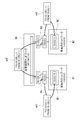
- FIG. 1 is a diagram schematically showing a train on which a railway vehicle network system according to an example of the first embodiment is mounted.
- FIG. 2 is a diagram for explaining the NAT processing.
- FIG. 3 is a schematic diagram illustrating an example of NAT processing.
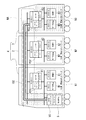
- FIG. 4 is a diagram schematically illustrating a train on which a railcar network system according to an example of the second embodiment is mounted.
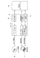
- FIG. 5 is a schematic diagram for explaining processing by a router incorporating a PPTP server in the second embodiment.
- FIG. 6 is a flowchart showing processing when the router receives a packet through the all-vehicle network in the second embodiment.
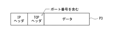
- FIG. 7 is a diagram illustrating a packet when connection control processing is performed in the second embodiment.
- FIG. 1 is a diagram schematically showing a train on which a railway vehicle network system according to an example of the first embodiment is mounted.
- FIG. 2 is a diagram for explaining the NAT processing.
- FIG. 3 is a schematic diagram illustrating
- FIG. 8 is a diagram for explaining tunnel processing in the second embodiment.
- FIG. 9 is a flowchart showing an outline of a tunnel and session establishment procedure in the second embodiment.
- FIG. 10 is a diagram for explaining a packet flow when a packet is transmitted from the maintenance terminal of the first car to the equipment of the third car in the second embodiment.
- FIG. 11 is a diagram for explaining the flow of a packet when a packet is sent from the No. 3 device to the No. 1 maintenance terminal in the second embodiment.
- information is transmitted and received between a maintenance target device selected by an external terminal and an external terminal that is not wired to the in-vehicle network where the maintenance target device exists.
- a maintenance target device selected by an external terminal and an external terminal that is not wired to the in-vehicle network where the maintenance target device exists.
- the external terminal can form the transmission line without being wired to any in-vehicle network.
- an external terminal is wired to any one in-vehicle network to form the transmission path, and further, the external terminal is wired to the in-vehicle network.
- the maintenance transmission path forming means transmits and receives information between the external terminal and the maintenance target device existing in the in-vehicle network to which the external terminal is wired.
- the transmission path is configured to be able to form a transmission path that does not go through the network address conversion unit of the vehicle on which the maintenance target device is mounted.
- FIG. 1 is a diagram schematically showing a train on which a railway vehicle network system according to an example of the first embodiment is mounted.
- the vehicle organization (train) 4 shown in FIG. 1 is configured by connecting a plurality of vehicles 1 to 3.
- the vehicles 1 to 3 are the first car (leading vehicle), the second car (intermediate vehicle), and the third car (rear vehicle) with the traveling direction on the left side of the page, but the number of vehicles included in the formation is limited to this. It is not something that can be done.
- a monitoring device M (M1 to M3) as a first device, a device A (A1 to A3) as a second device, and a wireless LAN access point AP (AP1 to AP3) Connected in-vehicle networks N1 to N3 are configured.
- a plurality of devices (device A, device B, device C,...) Are connected to the in-vehicle networks N1 to N3.
- the devices A, B, C, and the like are devices of the same type (for example, door opening / closing devices, air conditioning devices, lighting devices, vehicle control devices, etc.) mounted on each vehicle, and are provided in each device.
- Ethernet registered trademark
- an inter-vehicle network NA for transmitting information between the monitoring devices M1 to M3 is configured.
- Each of the vehicles 1 to 3 is provided with routers R1 to R3 that connect the in-vehicle networks N1 to N3 and the inter-vehicle network NA.
- a NAT table relating only to the monitor devices M1 to M3 connected to the in-vehicle networks N1 to N3 is recorded, and communication using the inter-vehicle network NA is performed by the monitor device. It is performed only between M1 and M3.
- the monitoring devices M1 to M3 of the vehicles 1 to 3 are connected to the devices (the devices A and B described above) mounted on the vehicles via the in-vehicle networks N1 to N3. Status is sent.
- the monitor devices M1 to M3 extract, from the device information acquired from the device, abnormal information indicating abnormal operation of the device (this is also one of device information) and operation information to be monitored such as normal operation information.
- the monitor devices M2 and M3 of vehicles other than the head vehicle transmit the operation information of the monitoring target device to the head device monitor device M1 via the inter-vehicle network NA.
- a display device (not shown) is connected to the monitoring device M1 of the leading vehicle, and the operation information of the device is visually displayed. For example, if an abnormality occurs in the opening / closing of a door or lighting of a lighting device during train operation, the abnormality information transmitted from the monitor devices M2 and M3 is displayed on the display device of the monitor device M1 of the leading vehicle and an alarm is given. A sound is generated to notify the driver of equipment abnormality.
- the device information of all the vehicles is aggregated by the monitoring device M1 of the leading vehicle, and the display device includes the device such as abnormality information. Information is displayed.
- the private IP addresses in the in-vehicle networks N1 to N3 are assigned to the same type of devices and devices. For example, “10.0.0.11” is assigned to the monitor devices M1 to M3, and “10.0.0.12” is assigned to the devices A1 to A3.
- FIG. 2 is a diagram for explaining the NAT process
- FIG. 3 is a schematic diagram showing an example of the NAT process.
- NAT processing Sn by the router is performed based on the NAT table Tn.
- the NAT processing Sn uses the destination address (global IP address) included in the IP header of the packet P1 based on the NAT table Tn.
- the packet is converted into an IP address, and the converted packet P2 is sent to the in-vehicle network.
- the source address (private IP address) included in the IP header is converted into a global IP address based on the NAT table Tn, and the converted packet P2 Is transmitted to the inter-vehicle network NA.
- the address conversion method related to the monitor device is recorded in the NAT table Tn.
- FIG. 3 as an example, NAT processing in the case where information is transmitted from the monitoring device M2 connected to the in-vehicle network N2 of the No. 2 vehicle to the monitoring device M1 connected to the in-vehicle network N1 of the leading vehicle (No. 1 vehicle). Is shown.
- address information ad1 indicates a destination and a source address included in an IP header of a packet transmitted from the monitoring apparatus M2 of the second car to the in-vehicle network N2.
- the address information ad2 indicates a destination and a source address included in an IP header of a packet that the router R2 receives from the monitor device M2 by NAT processing and sends the packet to the inter-vehicle network NA.
- the address information ad3 indicates the destination and source address included in the IP header of the packet that the router R1 receives from the inter-vehicle network NA and performs NAT processing and sends it to the in-vehicle network N1 of the first car.
- “TO:” is followed by a destination address
- FROM:” is followed by a transmission source address.
- the source address is converted and rewritten by the NAT processing of the router R2.
- the destination address is converted and rewritten by the NAT processing of the router R1.
- the maintenance work includes updating the software of the control device of the equipment mounted on the vehicle, acquiring log information such as an operation log from the control device of the equipment, and the like.
- the maintenance terminal 5 is a portable personal computer such as a notebook personal computer, and includes a display unit including a display, an input unit including a keyboard, and a control unit including a CPU and a memory.
- a program maintenance software for performing maintenance work, necessary information, and the like are stored in advance in the memory of the control unit.
- the control unit receives an input command from the input unit and controls the display unit.
- the maintenance worker can perform maintenance work by giving an input command to the control unit by operating the input unit of the maintenance terminal 5. Information necessary for the maintenance worker to operate the input unit is displayed on the screen of the display unit under the control of the control unit. Therefore, the maintenance worker can perform maintenance work by operating the input unit while viewing the screen of the display unit.
- wireless LAN access points AP1 to AP3 are connected to the in-vehicle networks N1 to N3.
- a wireless LAN adapter AD is connected to the maintenance terminal 5.
- the wireless LAN adapter AD may be built in the maintenance terminal 5.
- the wireless LAN access points AP1 to AP3 are set with different SSIDs (identification names) and transmit them as beacons.
- the maintenance transmission path forming means includes wireless LAN access points AP1 to AP3 and a wireless LAN adapter AD, and the maintenance terminal 5 is connected via the wireless LAN adapter AD and the wireless LAN access points AP1 to AP3. And a transmission path connecting the in-vehicle networks N1 to N3 where the maintenance target devices exist.
- a transmission path for transmitting and receiving maintenance information can be formed between the maintenance terminal 5 and the maintenance target device without using the NAT function of the routers R1 to R3 on which the maintenance target device is mounted. .
- FIG. 1 shows a case where the maintenance terminal 5 is brought into the vehicle 1 of the first car, and the devices (monitor device M3, device A3, etc.) mounted on the vehicle 3 of the third car are used as the maintenance target devices.
- the wireless LAN adapter AD is connected to the maintenance terminal 5, and the maintenance terminal 5 is directly connected to the in-vehicle network N3 of the third car via the wireless LAN access point AP3 as in the wireless LAN infrastructure mode.
- this connected state is schematically indicated by a white bold line 101, and the thick line 101 does not actually exist.
- the maintenance terminal 5 sets the SSID common to the wireless LAN access point AP3 of the No. 3 car. Set. As a result, the maintenance terminal 5 is connected to the in-vehicle network N3 of the third car.
- the maintenance terminal 5 stores the SSIDs of the wireless LAN access points AP1 to AP3 of the vehicles 1 to 3 in advance.
- the maintenance worker operates the input unit of the maintenance terminal 5 to select the maintenance target device from the devices mounted on the vehicle 3 of the third car so that communication with the maintenance target device can be performed. It is configured. In this communication, the private IP address of the maintenance target device is required.
- the same type of device installed in each vehicle is assigned the same address and stored in the maintenance terminal 5 in advance.
- the maintenance terminal 5 since the maintenance terminal 5 is logically directly connected to the in-vehicle network N3 of the third car, it can communicate with all devices connected to the in-vehicle network N3 of the third car.
- the update information is used as maintenance information.
- the log information such as an operation log from the control device of the maintenance target device (for example, the device A3)
- the log information stored in the memory or the like regarding the operation state of the maintenance target device is used as the maintenance information. Then, it is transmitted from the maintenance target device to the maintenance terminal 5.
- the maintenance terminal 5 can communicate with all devices connected to other in-vehicle networks N1 and N2, and can transmit / receive maintenance information to / from the selected maintenance target device. .
- the maintenance worker does not need to directly connect the maintenance terminal 5 to the maintenance target device at the time of the maintenance work.
- the maintenance worker brings the maintenance terminal 5 into a certain vehicle (for example, the head vehicle) and installs it in the vehicle.
- Maintenance work can be performed on all devices (including monitor devices) connected to the in-vehicle networks N1 to N3 without having to move to another vehicle while staying. Can be done efficiently.
- communication between all-vehicle network NA during normal train operation as communication only between monitor devices, an increase in traffic of all-vehicle network NA is suppressed, and NAT tables of routers R1 to R3 Management effort and security degradation can be suppressed.
- the maintenance terminal 5 When the device in the vehicle in which the maintenance terminal 5 is brought in is communicated as a maintenance target device, the maintenance terminal 5 is connected to the in-vehicle network of the vehicle in which it exists (in the example of FIG. 1, the vehicle of the leading vehicle 1). A wired connection may be made to the internal network N1).
- maintenance work can be performed from outside the vehicle without bringing the maintenance terminal 5 into the vehicle.
- the private IP address of the device connected to each in-vehicle network is assigned to the same type of device, and the maintenance terminal 5 stores it.
- the IP address may be identified from the name of the device using name resolution means such as DNS or NetBIOS over TCP / IP.
- name resolution means such as DNS or NetBIOS over TCP / IP.
- a method of dynamically assigning an IP address like DHCP may be adopted. In this case, it is necessary not to overlap with the IP address of the maintenance terminal 5, but for that purpose, the IP address of the maintenance terminal 5 may be fixed and excluded from the dynamic allocation target.
- An IP address may also be assigned using a dynamic assignment function.
- FIG. 4 is a diagram schematically showing a train on which a railcar network system according to an example of the second embodiment is mounted. Elements identical or corresponding to those in FIG. Detailed description is omitted.
- in-vehicle networks N1 to N3 are configured in the respective vehicles 1 to 3, and information is transmitted between the monitoring devices M1 to M3 in the entire vehicle formation 4.
- An inter-vehicle network NA for performing the above is configured.
- Each of the vehicles 1 to 3 is provided with routers R1 to R3 for connecting between the in-vehicle networks N1 to N3 and the all-to-vehicle network NA, and each of the routers R1 to R3 has an in-vehicle network N1.
- a NAT table relating only to the monitoring devices M1 to M3 connected to .about.N3 is recorded, and communication using the inter-vehicle network NA is performed only between the monitoring devices M1 to M3.
- the wireless LAN access points AP1 to AP3 as in the first embodiment are not provided, and each router R1 to R3 has a PPTP (Point to Point Tunneling Protocol) server as a VPN (virtual private network) server.
- PPTP Point to Point Tunneling Protocol
- VS1 to VS3 are provided.
- the PPTP client VC is provided as the VPN client in the maintenance terminal 5 without connecting the wireless LAN adapter AD as in the first embodiment to the maintenance terminal 5. Since each PPTP server VS1 to VS3 can be implemented as software operating on the hardware of the routers R1 to R3, it is possible to eliminate the need for additional hardware.
- the PPTP client VC is implemented as software that operates on the hardware of the maintenance terminal 5.
- the maintenance transmission path forming means includes a PPTP client VC which is an example of a VPN client and PPTP servers VS1 to VS3 which are examples of a VPN server.
- the PPTP client VC and the PPTP servers VS1 to VS3 are thus, a transmission path is formed to connect the maintenance terminal 5 and the in-vehicle networks N1 to N3 where the maintenance target device exists.
- a transmission path for transmitting and receiving maintenance information can be formed between the maintenance terminal 5 and the maintenance target device without using the NAT function of the routers R1 to R3 on which the maintenance target device is mounted.
- an example using PPTP for constructing a VPN will be described, but other similar methods capable of constructing a VPN can also be used.
- the monitoring devices M1 to M3 are performed between the monitoring devices M1 to M3 through the all-vehicle network NA, and the device information of all the vehicles is stored in the monitoring device M1 of the leading vehicle.
- the operation information and the like of the monitoring target device are displayed on a display device (not shown) that is aggregated and connected to the monitor device M1.
- the maintenance worker brings the maintenance terminal 5 into the vehicle 1 of the first car and makes a wired connection to the in-vehicle network N1 of the first car.
- the maintenance terminal 5 is brought into the vehicle 1 of the first car, connected to the in-vehicle network N1 of the first car, and is installed in the vehicle 3 of the third car (monitor device M3, equipment A3, etc. ) Is a maintenance target device. Note that the maintenance terminal 5 does not necessarily have to be brought into the vehicle as long as the maintenance terminal 5 and the in-vehicle network can be wired.
- the maintenance worker operates the input unit of the maintenance terminal 5 and selects one maintenance target device.
- the maintenance terminal 5 incorporating the PPTP client VC is connected to the router R3 incorporating the PPTP server VS3 of the third vehicle.
- the router R3 incorporating the PPTP server VS3 of the third vehicle After establishing a tunnel and session, which will be described later, communication with the device A3 becomes possible, and maintenance information can be transmitted and received.
- communication is performed between the PPTP client VC of the maintenance terminal 5 and the PPTP server VS3 of the third car.
- this state is schematically shown by a white bold line 102, and the thick line 102 does not actually exist.
- a separate communication path is not provided as in the first embodiment, but communication between monitor devices during normal train operation (monitor communication) and communication during maintenance work are the same communication path. (All-vehicle network NA) is shared. Therefore, the router needs to process the packets appropriately.
- FIG. 5 is a schematic diagram for explaining processing by a router incorporating a PPTP server
- FIG. 6 is a flowchart showing processing when the router receives a packet through the inter-vehicle network NA.
- PPTP communication is roughly divided.
- A Communication for establishing tunnel and session using TCP / IP
- b Communication using PPTP tunneling protocol.
- the PPTP client VC maintenance terminal 5
- the PPTP client VC establishes a tunnel and a session with the PPTP server operating in the router using (a), and then uses the network in the vehicle to be maintained using (b). Access the device.
- the router performs tunnel processing St when the protocol number of the received packet is 47, and performs connection control processing Sc when the destination port number is 1723 by the processing of steps S1 to S3.
- communication between monitor devices (monitor communication) is performed, and NAT processing Sn is performed.
- FIG. 5 as an example, communication between the monitoring apparatus M1 and the maintenance terminal 5 of the first car and the router R3 incorporating the PPTP server of the third car is shown.
- FIG. 7 is a diagram illustrating a packet when the connection control process Sc is performed.
- the destination port number included in the TCP header of this packet P3 is 1723.
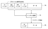
- FIG. 8 is a diagram for explaining the tunnel processing St. If the packet received from the inter-vehicle network NA is the packet P4 shown in FIG. 8 and the protocol number included in the leading IP header is 47, the router extracts the payload from the tunneling packet P4. .
- the process of extracting the payload from the tunneling packet P4 is the tunnel process St, and the extracted payload is the original packet P5.
- connection control process Sc and tunnel process St are performed by PPTP servers (VS1 to VS3) built in the routers (R1 to R3).
- FIG. 9 is a flowchart showing an outline of the tunnel and session establishment procedure according to (a) above, and the processing of the router (steps S21 to S27) is the connection control processing Sc.
- the router and PPTP server in the following description are the routers (R1 to R3) connected to the in-vehicle network to which the maintenance target device is connected and the PPTP servers (VS1 to VS3) built in the router.
- the PPTP client VC of the maintenance terminal 5 transmits a connection request by TCP to the standby port of the connection target router with the destination port number 1723 (in the case of PPTP, 1723) (step S11).
- the router receives the connection request (step S21), determines that it is a connection request with the destination port number, processes the packet with the processing routine of the PPTP server, and returns a connection response (success / failure) to the PPTP client VC (step S22). .
- the PPTP client VC receives the connection response (step S12), and if successful, continuously transmits a session start request (step S13).
- the session start request includes a “call ID” for identification.
- the PPTP server receives the session start request, performs the reception process, and returns a session start response (success / failure) (steps S23 to S25).
- the session start response includes “call ID” and “response ID” for identification.
- the PPTP client VC receives the session start response, and if successful, transmits a session connection completion (steps S14 to S15).
- the completion of session connection includes a “response ID” for identification.
- the PPTP server Upon receipt of the session connection completion, the PPTP server returns session information (communication option) that can be used in this session (steps S26 to S27).
- the session information includes a “call ID” for identification.
- a plurality of sessions can be established as necessary.
- the PPTP client VC receives the session information (step S16), and communicates using the tunneling protocol (b) (protocol number 47 in the case of PPTP) after establishing the session. If necessary, authentication processing such as CHAP and encryption procedure such as RC4 can be used together.
- FIG. 10 is a diagram for explaining a packet flow when a packet is transmitted from the maintenance terminal 5 connected to the in-vehicle network N1 of the first car to the device A3 of the third car.
- the original router R3 excluding the PPTP server VS1 of the first car and the PPTP server VS3 of the third car shown by shading in FIG. 10 are not involved in the transmission of this packet.
- address information ad11 to ad13 included in the header of the packet indicate “TO:” followed by a destination address and “FROM:” followed by a source address.
- the maintenance terminal 5 includes the PPTP client VC as software as described above, in addition to the maintenance software 5A that is a program for performing maintenance work.
- the maintenance software 5A running on the maintenance terminal 5 generates a packet addressed to the device A3 (10.0.0.12) and sends it to the PPTP client VC.
- the PPTP client VC generates a tunneling packet by newly adding a header (header including address information ad12) addressed to the third car from the known tunnel session information, and transmits it to the router R1 of the first car.
- the first car router R1 processes the received tunneling packet addressed to the third car with the NAT function, rewrites the source address with the global IP address of the maintenance terminal 5, and sends it to the inter-vehicle network NA. At this time, only the header added as a tunneling packet is rewritten, and the original packet generated by the maintenance software 5A is not rewritten. Therefore, only the address information ad12 is rewritten to the address information ad13.
- the tunneling packet is sent to the router R3 as the hardware of the third car via the all-vehicle network NA. Since the protocol number of the header of the tunneling packet is the specific number (47), it is sent to the PPTP server VS3. .
- the No. 3 PPTP server VS3 deletes the header of the tunneling packet, extracts the original packet generated by the maintenance software 5A (the above-described tunnel processing St), and sends it to the device A3 in the in-vehicle network N3 of the No. 3 car.
- the PPTP server VS3 of the third car uses the same private IP address as that of the maintenance terminal 5 so that packets from the equipment group of the in-vehicle network N3 of the third car to the maintenance terminal 5 can be appropriately processed. That is, as in this example, when the PPTP server VS3 and the router R3 operate on the same network device and the device is connected to the in-vehicle network N3 by one line, the line shares a plurality of IP addresses ( In the case of FIG. 10, the line has two IP addresses of router R3 10.0.0.1 and PPTP server VS3 10.0.0.10.)
- FIG. 11 is a diagram for explaining a packet flow when a packet is sent from the device A3 of the third car to the maintenance terminal 5 connected to the in-vehicle network N1 of the first car. Also in this case, the original router R3 excluding the PPTP server VS1 of the first car and the PPTP server VS3 of the third car shown by hatching in FIG. 11 are not involved in the transmission of this packet.
- address information ad21 to ad23 included in the header of the packet indicate “TO:” followed by a destination address and “FROM:” followed by a source address.
- the device A3 of the third car when the device A3 of the third car generates a packet addressed to the maintenance terminal 5 (maintenance software 5A) and sends it to the in-vehicle network 3N, it is delivered to the PPTP server VS3 having the same private IP address as the maintenance terminal 5.
- PPTP server VS3 newly adds a header (header including address information ad22) addressed to car 1 from known tunnel session information, generates a tunneling packet, and sends it to router R1 of car 1.
- the first car router R1 processes the received tunneling packet with the NAT function, rewrites the destination address to the private IP address of the maintenance terminal 5, and sends it to the first car in-vehicle network N1. At this time, only the header given as the tunneling packet is rewritten, and the original packet generated by the device A3 is not rewritten. Therefore, only the address information ad22 is rewritten to the address information ad23.
- the tunneling packet is sent to the maintenance terminal 5 via the in-vehicle network N1 of the first car, and the PPTP client VC deletes the header of the tunneling packet, extracts the original packet generated by the device A3, and transmits it to the maintenance software 5A.
- the maintenance terminal 5 (maintenance software 5A) and the device A3 can communicate as if they belong to the same in-vehicle network (local network). Similarly, the maintenance terminal 5 can communicate with all devices connected to the in-vehicle network N3 of the third car.
- the update information is used as maintenance information.
- the log information such as an operation log from the control device of the maintenance target device (for example, the device A3)
- the log information stored in the memory or the like regarding the operation state of the maintenance target device is used as the maintenance information. Then, it is transmitted from the maintenance target device to the maintenance terminal 5.
- the maintenance terminal 5 can communicate with all devices connected to the other in-vehicle networks N1 and N2, and can transmit / receive maintenance information to / from the selected maintenance target device. .
- the PPTP servers VS1 to VS3 do not necessarily have to be operated by being incorporated in the routers R1 to R3, and may be configured to be operated by another independent device.
- the maintenance worker does not need to directly connect the maintenance terminal 5 to the maintenance target device during the maintenance work, and the maintenance terminal 5 is connected to a certain vehicle (for example, the head vehicle).
- a certain vehicle for example, the head vehicle.
- communication between all-vehicle network NA during normal train operation as communication only between monitor devices, an increase in traffic of all-vehicle network NA is suppressed, and NAT tables of routers R1 to R3 Management effort and security degradation can be suppressed.
- the maintenance terminal 5 When communicating the equipment in the vehicle in which the maintenance terminal 5 is brought in as a maintenance target equipment, the maintenance terminal 5 is connected to the in-vehicle network of the vehicle in which the maintenance terminal 5 exists (in the example of FIG. 4, the vehicle of the leading vehicle 1).
- the maintenance terminal 5 may be a single device constituting the in-vehicle network without using PPTP by wire connection to the in-network N1).
- communication using the inter-vehicle network NA during normal train operation is communication only between monitor devices, but the present invention is not limited to this.
- the communication using the all-vehicle network NA is limited to the communication between a small number of specific devices (monitor devices, devices), thereby suppressing the increase in traffic of the all-vehicle network NA to some extent and the routers R1 to R3. It is possible to suppress the trouble of managing the NAT table and the decrease in security to some extent.
- the present invention is useful as a railway vehicle network system or the like that can suppress an increase in traffic of the network between all vehicles, suppress the trouble of managing the NAT table and a decrease in security, and can efficiently perform maintenance work. .
- Vehicle 4 Vehicle formation 5
- Maintenance terminal (external terminal) M1 to M3 monitor device (first device) A1 to A3 equipment (second equipment) N1 to N3 In-vehicle network NA All-to-vehicle network R1 to R3 Router AP1 to AP3 Wireless LAN access point AD Wireless LAN adapter VC PPTP client (VPN client) VS1 to VS3 PPTP server (VPN server)
Landscapes
- Engineering & Computer Science (AREA)
- Mechanical Engineering (AREA)
- Computer Networks & Wireless Communication (AREA)
- Signal Processing (AREA)
- Health & Medical Sciences (AREA)
- General Health & Medical Sciences (AREA)
- Computing Systems (AREA)
- Medical Informatics (AREA)
- Biomedical Technology (AREA)
- Small-Scale Networks (AREA)
Abstract
Description
図1は、第1実施形態の一例の鉄道車両のネットワークシステムを搭載した列車を模式的に示した図である。
図4は、第2実施形態の一例の鉄道車両のネットワークシステムを搭載した列車を模式的に示した図であり、図1と同一又は相当する要素には同一の参照符号を付して、その詳細な説明を省略する。
(a)TCP/IPを用いてトンネル及びセッションを確立するための通信
(b)PPTPトンネリングプロトコルを用いた通信
がある。PPTPクライアントVC(保守端末5)は、(a)を用いてルータで稼働しているPPTPサーバとの間で、トンネル及びセッションを確立した後、(b)を用いて保守対象とする車両内ネットワーク内の機器へアクセスする。
4 車両編成
5 保守端末(外部端末)
M1~M3 モニタ装置(第1の機器)
A1~A3 機器(第2の機器)
N1~N3 車両内ネットワーク
NA 全車両間ネットワーク
R1~R3 ルータ
AP1~AP3 無線LANアクセスポイント
AD 無線LANアダプタ
VC PPTPクライアント(VPNクライアント)
VS1~VS3 PPTPサーバ(VPNサーバ)
Claims (6)
- 複数の車両が連結された車両編成の各車両に搭載され、プライベートアドレスが付与される少なくとも第1及び第2の機器が接続された車両内ネットワークと、
前記車両編成の全体において、異なる前記車両に搭載された前記機器同士の間で情報の送受信を行うための全車両間ネットワークと、
各々の前記車両に、前記車両内ネットワークと前記全車両間ネットワークとの間に接続されて設けられ、異なる前記車両に搭載された前記機器同士の間で情報の送受信を行う際に、前記第1の機器の前記プライベートアドレスと前記全車両間ネットワークのIPアドレスとを相互に変換するアドレス変換を行うネットワークアドレス変換部を有するルータと、
前記車両編成を構成する各前記車両に搭載された前記第1及び第2の機器の中から外部端末によって選択される保守対象機器と、前記保守対象機器が存在する前記車両内ネットワークに有線接続されていない前記外部端末との間で、情報の送受信を行うための伝送路であって、前記保守対象機器が搭載された前記車両の前記ネットワークアドレス変換部を介さない伝送路を形成する保守用伝送路形成手段と、
を備えた鉄道車両のネットワークシステム。 - 前記保守用伝送路形成手段は、
各々の前記車両内ネットワークに接続された無線LANアクセスポイントと、
前記外部端末に接続または内蔵された無線LANアダプタとを有し、
前記無線LANアダプタ及び前記無線LANアクセスポイントを介して、前記外部端末と、前記保守対象機器が存在する前記車両内ネットワークとをつなぐ前記伝送路を形成する、
請求項1に記載の鉄道車両のネットワークシステム。 - 前記保守用伝送路形成手段は、
前記外部端末に内蔵され、いずれか1つの前記車両内ネットワークと接続されるVPNクライアントと、
各々の前記車両に、前記車両内ネットワークと前記全車両間ネットワークとの間に接続されて設けられるVPNサーバとを有し、
前記VPNクライアント及び前記VPNサーバを介して、前記外部端末と、前記保守対象機器が存在する前記車両内ネットワークとをつなぐ前記伝送路を形成する、
請求項1に記載の鉄道車両のネットワークシステム。 - 前記外部端末は、前記保守用伝送路形成手段により形成された前記伝送路を介して、前記保守対象機器のソフトウェアを更新する、
請求項1~3のいずれかに記載の鉄道車両のネットワークシステム。 - 前記外部端末は、前記保守用伝送路形成手段により形成された前記伝送路を介して、前記保守対象機器の動作ログを受信する、
請求項1~4のいずれかに記載の鉄道車両のネットワークシステム。 - 各々の前記車両の前記第1の機器は、前記車両内ネットワークを介して前記第2の機器の状態を監視するモニタ装置であり、
前記全車両間ネットワークを介して、各前記車両の各前記モニタ装置間で、各前記第2の機器の状態に関する情報を送受信する、
請求項1~5のいずれかに記載の鉄道車両のネットワークシステム。
Priority Applications (2)
| Application Number | Priority Date | Filing Date | Title |
|---|---|---|---|
| SG11201705902YA SG11201705902YA (en) | 2015-01-30 | 2016-01-26 | Network system of railcar |
| US15/547,661 US10263806B2 (en) | 2015-01-30 | 2016-01-26 | Network system of railcar |
Applications Claiming Priority (2)
| Application Number | Priority Date | Filing Date | Title |
|---|---|---|---|
| JP2015016521A JP6353377B2 (ja) | 2015-01-30 | 2015-01-30 | 鉄道車両のネットワークシステム |
| JP2015-016521 | 2015-01-30 |
Publications (1)
| Publication Number | Publication Date |
|---|---|
| WO2016121374A1 true WO2016121374A1 (ja) | 2016-08-04 |
Family
ID=56542996
Family Applications (1)
| Application Number | Title | Priority Date | Filing Date |
|---|---|---|---|
| PCT/JP2016/000367 Ceased WO2016121374A1 (ja) | 2015-01-30 | 2016-01-26 | 鉄道車両のネットワークシステム |
Country Status (4)
| Country | Link |
|---|---|
| US (1) | US10263806B2 (ja) |
| JP (1) | JP6353377B2 (ja) |
| SG (1) | SG11201705902YA (ja) |
| WO (1) | WO2016121374A1 (ja) |
Cited By (4)
| Publication number | Priority date | Publication date | Assignee | Title |
|---|---|---|---|---|
| WO2018055774A1 (ja) * | 2016-09-26 | 2018-03-29 | 株式会社日立国際電気 | 車両監視システム、管理装置、及び監視方法 |
| JP2018523929A (ja) * | 2016-02-23 | 2018-08-23 | 中▲車▼青▲島▼四方▲車▼▲輛▼研究所有限公司Crrc Qingdao Sifang Rolling Stock Research Institute Co.,Ltd. | 列車制御ネットワークと列車運行ネットワークとを組み合わせたブロードバンド通信ネットワークアーキテクチャおよびその通信方法 |
| CN110395296A (zh) * | 2019-08-13 | 2019-11-01 | 北京交大思诺科技股份有限公司 | 一种新型lkj记录单元 |
| CN110520838A (zh) * | 2017-04-05 | 2019-11-29 | 西门子交通有限公司 | 配置网络中的至少一个装置的方法、计算机程序和计算机可读存储介质 |
Families Citing this family (11)
| Publication number | Priority date | Publication date | Assignee | Title |
|---|---|---|---|---|
| DE102015218906B4 (de) * | 2015-09-30 | 2021-06-10 | Siemens Mobility GmbH | Verfahren zum Betreiben eines Datenübertragungssystems und Datenübertragungssystem |
| JP6852495B2 (ja) * | 2017-03-23 | 2021-03-31 | 富士通株式会社 | アドレス変換装置、情報処理システム及び情報処理システムの制御方法 |
| JP6966877B2 (ja) * | 2017-06-07 | 2021-11-17 | 株式会社日立製作所 | 車両ネットワークシステム、端末接続装置、及び端末接続方法 |
| DE102017211153A1 (de) * | 2017-06-30 | 2019-01-03 | Siemens Aktiengesellschaft | Verfahren und Vorrichtung zum Übertragen von Daten zwischen einem ersten Kommunikationsnetz einer ersten spurgebundenen Fahrzeugeinheit und einem zweiten Kommunikationsnetz einer zweiten spurgebundenen Fahrzeugeinheit |
| JP6899741B2 (ja) * | 2017-09-05 | 2021-07-07 | 株式会社メガチップス | 電力線通信システム、端末装置、プログラムおよび電力線通信システムのメンテナンス方法 |
| JP6831114B2 (ja) * | 2018-03-30 | 2021-02-17 | サイレックス・テクノロジー株式会社 | 中継装置、中継方法、及び、プログラム |
| DE102018207515A1 (de) * | 2018-05-15 | 2019-11-21 | Siemens Mobility GmbH | Verfahren und Zugangsvorrichtung zum Bereitstellen eines datentechnischen Zugangs zu einem Fahrzeugnetz eines spurgebundenen Fahrzeugs |
| DE102019208098B3 (de) * | 2019-06-04 | 2020-08-13 | Continental Automotive Gmbh | Kraftfahrzeug mit Antennennetzwerk |
| CN112298222B (zh) * | 2019-07-30 | 2022-12-09 | 株洲中车时代电气股份有限公司 | 一种轨道车辆及其通信网络 |
| CN111257017B (zh) * | 2020-01-06 | 2022-05-13 | 中车株洲电力机车有限公司 | 一种列车及其库内辅机的测试方法以及系统 |
| US20240262400A1 (en) * | 2023-02-08 | 2024-08-08 | Buckeye Mountain, Inc. | System and Method for Obtaining, Transmitting and Maintaining Automated Single-Car Test Device Railway Brake Test Results |
Citations (2)
| Publication number | Priority date | Publication date | Assignee | Title |
|---|---|---|---|---|
| JP2011205777A (ja) * | 2010-03-25 | 2011-10-13 | Koito Ind Ltd | 車両編成用の車両ネットワークシステムおよび車両ネットワーク制御装置 |
| JP2011205582A (ja) * | 2010-03-26 | 2011-10-13 | Hitachi Kokusai Electric Inc | ネットワーク管理システムおよびネットワーク間接続装置 |
Family Cites Families (8)
| Publication number | Priority date | Publication date | Assignee | Title |
|---|---|---|---|---|
| US6334654B1 (en) * | 1996-09-13 | 2002-01-01 | New York Air Brake Corporation | Integrated train electrical and pneumatic brakes |
| US20050174974A1 (en) * | 2003-08-19 | 2005-08-11 | Sonntag Artur H. | System and method for roaming in data -and communication- networks |
| US20050259598A1 (en) * | 2004-05-21 | 2005-11-24 | Shawn Griffin | Dynamically forming wireless local area networks |
| US8090858B2 (en) * | 2004-07-23 | 2012-01-03 | Nokia Siemens Networks Oy | Systems and methods for encapsulation based session initiation protocol through network address translation |
| KR100689554B1 (ko) * | 2004-10-07 | 2007-03-02 | 삼성전자주식회사 | 광대역 무선 접속 통신 시스템에서 옥내 및 옥외 무선접속을 제공하는 장치 및 방법 |
| US8037204B2 (en) | 2005-02-11 | 2011-10-11 | Cisco Technology, Inc. | Method and system for IP train inauguration |
| US8812688B2 (en) * | 2010-09-28 | 2014-08-19 | Nokia Corporation | Method and apparatus for providing shared connectivity |
| CA2900522C (en) * | 2013-03-13 | 2019-10-29 | Wabtec Holding Corp. | Train network management system and method |
-
2015
- 2015-01-30 JP JP2015016521A patent/JP6353377B2/ja active Active
-
2016
- 2016-01-26 SG SG11201705902YA patent/SG11201705902YA/en unknown
- 2016-01-26 US US15/547,661 patent/US10263806B2/en active Active
- 2016-01-26 WO PCT/JP2016/000367 patent/WO2016121374A1/ja not_active Ceased
Patent Citations (2)
| Publication number | Priority date | Publication date | Assignee | Title |
|---|---|---|---|---|
| JP2011205777A (ja) * | 2010-03-25 | 2011-10-13 | Koito Ind Ltd | 車両編成用の車両ネットワークシステムおよび車両ネットワーク制御装置 |
| JP2011205582A (ja) * | 2010-03-26 | 2011-10-13 | Hitachi Kokusai Electric Inc | ネットワーク管理システムおよびネットワーク間接続装置 |
Cited By (8)
| Publication number | Priority date | Publication date | Assignee | Title |
|---|---|---|---|---|
| JP2018523929A (ja) * | 2016-02-23 | 2018-08-23 | 中▲車▼青▲島▼四方▲車▼▲輛▼研究所有限公司Crrc Qingdao Sifang Rolling Stock Research Institute Co.,Ltd. | 列車制御ネットワークと列車運行ネットワークとを組み合わせたブロードバンド通信ネットワークアーキテクチャおよびその通信方法 |
| WO2018055774A1 (ja) * | 2016-09-26 | 2018-03-29 | 株式会社日立国際電気 | 車両監視システム、管理装置、及び監視方法 |
| JPWO2018055774A1 (ja) * | 2016-09-26 | 2019-06-24 | 株式会社日立国際電気 | 車両監視システム、管理装置、及び監視方法 |
| US10618529B2 (en) | 2016-09-26 | 2020-04-14 | Hitachi Kokusai Electric Inc. | Vehicle monitoring system, management device and monitoring method |
| CN110520838A (zh) * | 2017-04-05 | 2019-11-29 | 西门子交通有限公司 | 配置网络中的至少一个装置的方法、计算机程序和计算机可读存储介质 |
| CN110520838B (zh) * | 2017-04-05 | 2022-08-19 | 西门子交通有限公司 | 配置网络中的至少一个装置的方法 |
| CN110395296A (zh) * | 2019-08-13 | 2019-11-01 | 北京交大思诺科技股份有限公司 | 一种新型lkj记录单元 |
| CN110395296B (zh) * | 2019-08-13 | 2021-04-09 | 北京交大思诺科技股份有限公司 | 一种新型lkj记录单元 |
Also Published As
| Publication number | Publication date |
|---|---|
| JP6353377B2 (ja) | 2018-07-04 |
| US20180013580A1 (en) | 2018-01-11 |
| JP2016143945A (ja) | 2016-08-08 |
| US10263806B2 (en) | 2019-04-16 |
| SG11201705902YA (en) | 2017-09-28 |
Similar Documents
| Publication | Publication Date | Title |
|---|---|---|
| JP6353377B2 (ja) | 鉄道車両のネットワークシステム | |
| US8380819B2 (en) | Method to allow seamless connectivity for wireless devices in DHCP snooping/dynamic ARP inspection/IP source guard enabled unified network | |
| US10171499B2 (en) | Zone-based security architecture for intra-vehicular wireless communication | |
| EP3783843A1 (en) | Method and apparatus for transmitting message | |
| US20120257529A1 (en) | Computer system and method of monitoring computer system | |
| JP7095102B2 (ja) | ネットワークデバイス間にグループネットワークを作成するためのシステムおよび方法 | |
| US20110299538A1 (en) | Apparatus for providing connection between networks | |
| EP3119047A1 (en) | Load balancing method, apparatus and system | |
| WO2015127852A1 (zh) | 无线局域网隧道建立方法、装置及接入网系统 | |
| CN110945855A (zh) | 通过地址空间聚合的虚拟化网络功能 | |
| CN110324159B (zh) | 链路配置方法、控制器和存储介质 | |
| CN103607345A (zh) | 一种监控节点建立路由信息的方法和系统 | |
| CN105939267A (zh) | 带外管理方法及装置 | |
| CN116743742A (zh) | OpenVPN集群及其实例间通信方法、云网关 | |
| US8542634B2 (en) | Method and apparatus for providing mobility to a mobile node | |
| CN111064814B (zh) | 基于PCP的VxLAN NAT穿越的方法、系统和网关 | |
| CN104301449A (zh) | 一种修改ip地址的方法和装置 | |
| CN109743316A (zh) | 数据传输方法、出口路由器、防火墙及双台防火墙系统 | |
| CN112911001A (zh) | 一种云vpn与企业网自动化组网方案 | |
| CN106534290B (zh) | 一种自适应被维护设备ip地址的维护方法及装置 | |
| US9906498B2 (en) | Method for setting up a secure communication connection, a communication device and connection controller | |
| JP2005136739A (ja) | データ中継方法、データ中継装置、データ中継システム | |
| JPWO2019171825A1 (ja) | ネットワークアドレス指定方法、管制局及び地球局 | |
| JP6360012B2 (ja) | ネットワーク統合システムおよびネットワーク統合方法 | |
| EP3890249A1 (en) | A method and a system for routing data packets in a network |
Legal Events
| Date | Code | Title | Description |
|---|---|---|---|
| 121 | Ep: the epo has been informed by wipo that ep was designated in this application |
Ref document number: 16742978 Country of ref document: EP Kind code of ref document: A1 |
|
| WWE | Wipo information: entry into national phase |
Ref document number: 15547661 Country of ref document: US |
|
| NENP | Non-entry into the national phase |
Ref country code: DE |
|
| WWE | Wipo information: entry into national phase |
Ref document number: 11201705902Y Country of ref document: SG |
|
| 122 | Ep: pct application non-entry in european phase |
Ref document number: 16742978 Country of ref document: EP Kind code of ref document: A1 |