WO2016121109A1 - 潮流発電装置 - Google Patents
潮流発電装置 Download PDFInfo
- Publication number
- WO2016121109A1 WO2016121109A1 PCT/JP2015/052710 JP2015052710W WO2016121109A1 WO 2016121109 A1 WO2016121109 A1 WO 2016121109A1 JP 2015052710 W JP2015052710 W JP 2015052710W WO 2016121109 A1 WO2016121109 A1 WO 2016121109A1
- Authority
- WO
- WIPO (PCT)
- Prior art keywords
- tidal current
- power generation
- rotating body
- current power
- guidance
- Prior art date
- Legal status (The legal status is an assumption and is not a legal conclusion. Google has not performed a legal analysis and makes no representation as to the accuracy of the status listed.)
- Ceased
Links
Images



Classifications
-
- F—MECHANICAL ENGINEERING; LIGHTING; HEATING; WEAPONS; BLASTING
- F03—MACHINES OR ENGINES FOR LIQUIDS; WIND, SPRING, OR WEIGHT MOTORS; PRODUCING MECHANICAL POWER OR A REACTIVE PROPULSIVE THRUST, NOT OTHERWISE PROVIDED FOR
- F03B—MACHINES OR ENGINES FOR LIQUIDS
- F03B13/00—Adaptations of machines or engines for special use; Combinations of machines or engines with driving or driven apparatus; Power stations or aggregates
- F03B13/12—Adaptations of machines or engines for special use; Combinations of machines or engines with driving or driven apparatus; Power stations or aggregates characterised by using wave or tide energy
- F03B13/26—Adaptations of machines or engines for special use; Combinations of machines or engines with driving or driven apparatus; Power stations or aggregates characterised by using wave or tide energy using tide energy
-
- Y—GENERAL TAGGING OF NEW TECHNOLOGICAL DEVELOPMENTS; GENERAL TAGGING OF CROSS-SECTIONAL TECHNOLOGIES SPANNING OVER SEVERAL SECTIONS OF THE IPC; TECHNICAL SUBJECTS COVERED BY FORMER USPC CROSS-REFERENCE ART COLLECTIONS [XRACs] AND DIGESTS
- Y02—TECHNOLOGIES OR APPLICATIONS FOR MITIGATION OR ADAPTATION AGAINST CLIMATE CHANGE
- Y02E—REDUCTION OF GREENHOUSE GAS [GHG] EMISSIONS, RELATED TO ENERGY GENERATION, TRANSMISSION OR DISTRIBUTION
- Y02E10/00—Energy generation through renewable energy sources
- Y02E10/20—Hydro energy
-
- Y—GENERAL TAGGING OF NEW TECHNOLOGICAL DEVELOPMENTS; GENERAL TAGGING OF CROSS-SECTIONAL TECHNOLOGIES SPANNING OVER SEVERAL SECTIONS OF THE IPC; TECHNICAL SUBJECTS COVERED BY FORMER USPC CROSS-REFERENCE ART COLLECTIONS [XRACs] AND DIGESTS
- Y02—TECHNOLOGIES OR APPLICATIONS FOR MITIGATION OR ADAPTATION AGAINST CLIMATE CHANGE
- Y02E—REDUCTION OF GREENHOUSE GAS [GHG] EMISSIONS, RELATED TO ENERGY GENERATION, TRANSMISSION OR DISTRIBUTION
- Y02E10/00—Energy generation through renewable energy sources
- Y02E10/30—Energy from the sea, e.g. using wave energy or salinity gradient
Definitions
- the present invention relates to a tidal current power generation device.
- Tidal current power generation converts seawater flow (tidal current) into electrical energy, so how to capture the energy of seawater flow is directly linked to improved power generation efficiency.
- an object of the present invention is to provide a tidal current power generation apparatus that captures the energy of seawater flow more efficiently in order to improve power generation efficiency of tidal current power generation.
- the main present invention that solves the above-described problems includes a rotating body that rotates in response to a tidal current from the upstream side to the downstream side in the sea, a power generation device that generates electric power based on the rotational force of the rotating body, and the underwater And a guidance device having an inclined surface for guiding the tidal current so that the tidal current is directed to the rotating body at a position lower than the rotating body.
- the power generation efficiency of tidal power generation can be improved.
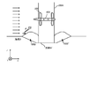
- FIG. 1 is a perspective view of the tidal power generation device
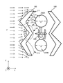
- FIG. 2 is a plan view of the tidal power generation device
- FIG. 3 is a side view of the tidal power generation device.
- the arrow F in a figure shows the flow direction of a tidal current.
- the Z axis is an axis indicating the height direction between the seabed B and the sea surface
- the X axis is an axis indicating the flow direction of the tidal current (the direction connecting the upstream side and the downstream side).
- the Y axis is an axis indicating a direction orthogonal to the X axis and the Z axis (a direction intersecting with the direction connecting the upstream side and the downstream side).
- the “X direction”, the “Y direction”, and the “Z direction” are respectively represented, the direction indicated by the arrow is the + direction, and the direction opposite to the arrow is the ⁇ direction.
- the direction from the seabed B toward the sea surface (+ Z direction) is expressed as “high” and “above” as the positional relationship.
- the tidal current power generation device is disposed in the sea and includes a guidance device 100, piers 200A and 200B, a rotating body 300, and a power generation device 400.
- the tidal current power generation device is a facility that improves the power generation efficiency of the power generation device 400 by changing the flow of the tidal current between the guidance device 100 and the piers 200A and 200B.
- the bridge piers 200A and 200B are foundations that support the bridge on the sea, and are, for example, a columnar concrete structure that extends in the sea surface direction from the buried area under the seabed B.
- the pier 200A and the pier 200B are disposed adjacent to each other in the Y direction, and a gap M is formed in the Y direction between the pier 200A and the pier 200B.
- Rotating body 300 is a propeller composed of three plate-like bodies attached to the front surface portion of power generation device 400 and three plate-like bodies attached to the rear surface portion. Then, the three plate-like bodies of the front surface portion and the rear surface portion of the rotating body 300 rotate in response to the tidal current F from the upstream side to the downstream side, and transmit the rotational force to the bearing extending in the housing of the power generation apparatus 400. .
- the rotary body 300 which concerns on this embodiment has increased the rotational force of a bearing by having a propeller in a front surface part and a rear surface part.
- the power generation device 400 is a generator that generates power based on the rotational force of the rotating body 300, and is, for example, a permanent magnet generator.
- the power generation apparatus 400 generates power by generating an electromotive force in a conducting wire wound around the bearing by installing a bearing rotated by the rotating body 300 in a magnetic field generated by a permanent magnet.
- the power generation apparatus 400 converts the generated power into AC power having a predetermined frequency by a power conditioner, and transmits the power to a substation on the ground by a transmission line (not shown).
- the power generation device 400 is fixed to the pier 200A via a fixing member.
- the rotating body 300 attached to the power generation device 400 is installed in the gap M between the pier 200A and the pier 200B.
- the guiding device 100 is a device that guides the tidal current F toward the rotating body 300 and prevents scouring the piers 200A and 200B.
- the guidance device 100 is a weir having a height of about 1 m formed of concrete on the seabed B, for example.
- the guidance apparatus 100 is arrange
- the interval in the flow direction of the tidal current F between the guidance device 100 and the piers 200A and 200B is shorter than the diameter R of the piers 200A and 200B at each adjacent position. It is a distance.
- interval of the flow direction of the tidal current F of the guidance apparatus 100 and the bridge piers 200A and 200B is the downstream surface (FIG. 3) as represented by H1, H2, H3, H4, and H5 in FIG. This means the straight line distance when a straight line is extended from the surface b) to the surface position of the pier 200A, 200B in the flow direction of the tidal current F.
- the guidance device 100 includes a guidance unit 110 that guides the tidal current F in the vicinity of the seabed B so as to rise toward the rotating body 300, a first end 111 that extends in the + Y direction from the guidance unit 110, and a guidance unit 110.
- the second end 112 extends in the ⁇ Y direction.
- the guiding unit 110 of the guiding device 100 has an inclined surface (a surface shown in FIG. 3) on the surface facing the upstream side, and has a V-shaped shape that widens from the downstream side toward the upstream side.
- the inclined surface of the guiding portion 110 is a surface formed on the surface facing the upstream side of the guiding device 100, and the rotator 300 is installed on the extended line in the inclined direction so that the tidal current F near the seabed B is obtained. Is guided toward the rotating body 300.
- the extended line in the tilt direction means substantially on the extended line, and means that the amount of water passing at the position of the rotating body 300 increases.
- the inclined surface (a surface) is, for example, an angle of approximately 20 to 45 degrees toward the downstream side with respect to the seabed B (in FIG. 3). Formed ⁇ ).
- the surface (b surface shown in FIG. 3) on the downstream side with respect to the tidal current F of the guiding portion 110 has a shape inclined toward the upstream side with respect to the seabed B.
- V-shaped shape of the guiding portion 110 also faces the downstream end so as to face the gap M, that is, the installation direction of the rotating body 300 in order to guide the tidal current F toward the rotating body 300. It is arranged like this.
- the first end portion 111 of the guidance device 100 is a portion extending from the guidance portion 110 of the guidance device 100 in the + Y direction.
- the second end portion 112 of the guidance device 100 is a portion that extends in the ⁇ Y direction from the guidance portion 110 of the guidance device 100.
- the 1st end part 111 and the 2nd end part 112 exhibit the shape which goes to the downstream from the upstream as it leaves
- the first end portion 111 and the second end portion 112 have an inclined surface that faces the upstream side and faces the downstream side in the same manner as the guide portion 110.
- the guiding device 100 ′ having the same structure is disposed at the upstream position with respect to the tidal current from the opposite direction. is doing. That is, the tide flows from the shore side to the shore side at high tide, but from the shore side to the shore side at low tide. Therefore, in the tidal current power generation apparatus according to the present embodiment, the guidance device 100 is disposed to correspond to the tidal current F at high tide, and the guidance device 100 ′ is disposed to correspond to the tidal current F ′ at low tide.
- the guiding device 100 ′ includes a guiding unit 110 ′ that guides the tidal current F ′ from the shore side toward the offshore side toward the rotating body 300, and a first end portion 111 ′ that extends in the + Y direction from the guiding unit 110 ′.
- the second end portion 112 ′ extending in the ⁇ Y direction from the guiding portion 110 ′ guides the tidal current F ′ toward the rotating body 300 and prevents scouring the piers 200A and 200B (the guiding device 100 ′ Since the structure is the same as that of the guidance device 100, it is hereinafter collectively referred to as “guidance device 100.” In FIG. 1, the guidance device 100 ′ is omitted.
- the horizontal direction of the rotating body 300 can be freely changed according to the tidal current direction.
- the rotating body 300 and the power generation device 400 may be supported by a base portion that freely swivels in the horizontal direction (XY direction), and the base portion may be swung using stress in the flow direction of the tidal current.
- the tidal current F ′ from the shore side to the offshore side when the tidal current F ′ from the shore side to the offshore side is reversed, it is opposite to the case of the tidal current F from the shore side to the shore side.
- You may comprise by the rotary body 300 which rotates in a direction, and the electric power generating apparatus 400 which has a power conditioner which can be rectified also by rotation of a reverse direction. In this case, the structure for turning the rotating body 300 and the power generation device 400 is not necessary.
- the flow of the tidal current F is changed by the induction device 100 and the piers 200A and 200B, so that the rotating body 300 can easily capture the energy of the tidal current F.
- induction part 110 of the guidance apparatus 100 has the inclined surface in the surface facing upstream, and is exhibiting the V shape which spreads as it goes to the upstream from the downstream.
- the tidal current F near the seabed B is guided in the inclination direction of the inclined surface.
- the tidal current F near the seabed B is guided in the direction of convergence of the V-shaped shape in the horizontal direction. Therefore, the tidal current F is induced from the vertical direction and the horizontal direction, and the flow velocity can be increased in the vicinity of the rotating body 300 disposed at the induction position.
- the rotating body 300 is disposed in the gap M between the pier 200A and the pier 200B. Since the flow path narrows in the gap M, the flow velocity of the tidal current F increases. In particular, in this embodiment, since the pier 200A and the pier 200B have a cylindrical shape, a region that converges in the flow direction of the tidal current F (region in which the interval in the Y direction becomes narrower) is formed in the gap M. Therefore, the flow velocity can be increased as compared with the case where it is formed in a quadrangular prism shape.
- the scouring in the vicinity of the pier 200A and the pier 200B is prevented by changing the flow of the tide F near the seabed B of the pier 200A and the pier 200B by the guidance device 100. ing.
- the scouring of the pier is caused by the tidal current that collided with the pier generates a downward flow and a vortex, which winds up the gravel on the seabed and the gravel is swept away.
- the guiding portion 110 of the guiding device 100 has a V-shaped shape with the downstream end facing the gap M, and the first end 111 and the second end.
- the part 112 exhibits a shape from the upstream side toward the downstream side as the distance from the gap M increases.
- the guiding portion 110, the first end portion 111, and the second end portion 112 of the guiding device 100 cause an upward tidal current F due to an inclined surface facing upward on the downstream side, and collide with the upper layer of the piers 200A and 200B.
- the downward flow of the tidal current F is offset. That is, the area between the guidance device 100 and the piers 200A and 200B is a stagnation point.
- the tidal current power generation apparatus by changing the tidal current, power generation efficiency of tidal power generation can be improved and scouring of the pier can be prevented.
- the inclination angle of the inclined surface of the guiding portion 110 of the guiding device 100 is set to an angle of approximately 20 to 45 degrees from the seabed B, and the interval in the flow direction between the guiding device 100 and the piers 200A and 200B is defined as the pier.
- the distance was shorter than the diameter R of 200A and 200B.
- the material is arbitrary, For example, even if it comprises a metal net with the external shape which became the shape of the induction
- a plurality of members may be installed on the seabed B to shape the guidance device 100.
- the direction of the tidal current F became reverse according to tide fullness, it was set as the aspect which arrange
- the guidance device 100 corresponding to only one direction may be provided.
- induction apparatus 100 is provided with the inclined surface which inclines to the downstream from the seabed B in the surface facing the upstream, and the shape which spreads in a V shape as it goes downstream from the upstream.
- the mode to present was shown.
- the shape of the guiding portion 110 may be other shapes as long as the tidal current F can be efficiently guided toward the rotating body 300.
- it may have a U-shaped shape as it goes from the downstream side to the upstream side.
- only the side facing the upstream side of the guiding portion 110 may exhibit a shape that expands in a V shape from the downstream side toward the upstream side.
- the tidal current power generation device is different from the first embodiment in that the guidance device 100B is formed by depositing particulate matter. According to the present embodiment, the flow direction of the tidal current is changed similarly to the first embodiment, and the same effect as the first embodiment can be obtained. In addition, the support ground on which the piers 200A and 200B are disposed is provided. This is useful because scouring can be prevented and the environmental load can be reduced. In addition, description is abbreviate
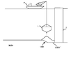
- 5 is a perspective view of the tidal power generation device
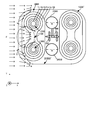
- FIG. 6 is a plan view of the tidal power generation device viewed from the sea surface direction
- FIG. 7 is a side view of the tidal power generation device viewed from the position of the power generation device.
- the tidal current power generation device includes a guidance device 100B, piers 200A and 200B, a rotating body 300, and a power generation device 400. And the structure of bridge pier 200A, 200B, the rotary body 300, and the electric power generating apparatus 400 is the same as that of 1st Embodiment.
- the guidance device 100B is formed by depositing a granular material having a particle size of about 20 mm, for example, a coal ash granulated material.
- Coal ash granulated material is a granular material mainly composed of coal ash formed by mixing and stirring cement and water with coal ash (fly ash) produced by burning coal. is there.
- Coal ash granulated material has a shear strength and adhesiveness higher than that of natural sand, in addition to being able to increase the particle size, and therefore is less likely to slip. Further, the coal ash granule has high strength and can form stable soil even when used as a banking material.
- coal ash granulate is mainly composed of coal ash, it has the effect of improving water quality by preventing the phosphorus accumulated in the seabed from solidifying and eluting into the water. Less environmental impact than forming a structure. Therefore, in this embodiment, the guidance device 100B is formed using coal ash granulated material, thereby preventing scouring of the supporting ground and reducing the environmental load.
- the guidance device 100B is disposed on the seabed B and includes a guidance unit 110B, a first deposition unit 120B, and a second deposition unit 130B.
- 6 represent contour lines of the guidance device 100B formed by depositing particulate matter on the seabed B.
- the first accumulation part 120B and the second accumulation part 130B are mountain-like granular piles arranged at positions upstream of the pier 200A and the pier 200B, respectively.
- the first accumulation portion 120B and the second accumulation portion 130B are formed by intensively dropping granular materials near the respective vertex positions.
- the diameters N2 of the bottom surfaces of the first deposition part 120B and the second deposition part 130B are formed to be substantially the same. Further, the diameter N2 of the bottom surface of the first accumulation portion 120B and the second accumulation portion 130B is formed to be larger than the diameter R of the pier 200A and the pier 200B in order to prevent scouring the pier 200A and the pier 200B. Yes.
- the diameter N2 of the bottom surface of the first accumulation portion 120B and the second accumulation portion 130B is when the position where the line segment extending from the apex position of the mountain shape in the inclination direction of the mountain and the seabed B intersects is the bottom surface. It is the diameter of the substantially circular shape formed in.
- the distance N1 between the top of the first deposition unit 120B and the top of the second deposition unit 130B is such that the guiding unit 110B is formed in the region between the first deposition unit 120B and the second deposition unit 130B.
- the first and second depositing portions 120B and 130B are set to be not more than twice the diameter N2 of the bottoms of the mountain-like shape.
- the guiding part 110B formed by the avalanche of the granular material has the contour line T3 of the first deposition part 120B and the second deposition part 130B on the side facing the upstream side, as indicated by the U line in FIG.
- An inclined surface that faces the downstream side is formed with the region between the contour line T3 and the contour line T3 as the apex of the height position.
- the guidance part 110B is exhibiting the shape which spreads in a U shape toward the upstream from the downstream in the horizontal direction. Further, the downstream end portion of the U-shaped shape of the guiding portion 110B is disposed so as to face the gap M.
- the guidance device 100B is formed on the concave portion B 'formed in the seabed B (a surrounding line T6 in FIG. 6 represents a groove shape of the concave portion B').
- the concave portion B ′ formed on the seabed B is provided with the pier 200A and the pier 200B formed by excavating the soft layer on the surface of the seabed B in order to expose the supporting ground on which the piers 200A and 200B are disposed. It is the groove
- the particle size of the granular material is desirably set to 3 to 5 times the particle size of the bottom material of the supporting ground based on the known filter theory.
- the guidance device 100B ′ having the same structure is disposed at a position before the tidal current in the reverse direction of the piers 200A and 200B, as in the first embodiment (see FIG. In FIG. 5, the guidance device 100B ′ is omitted).
- the soft layer of the seabed B where the piers 200A and 200B are disposed is excavated to form a recess B 'so that the layer serving as the supporting ground is exposed.
- a bridge pier 200A having a height protruding above the sea surface and a caisson K for forming the pier 200B are erected in the recess B '.
- the first depositing portion 120B and the second depositing portion 130B of the guidance device 100B are formed so that the coal ash granulate having a particle size of about 20 mm is embedded in the recess B ′.
- the coal ash granulation is dropped by, for example, putting the coal ash granulation into the bucket L and dropping the bucket L from the material carrier P on the sea below the sea level.
- the coal ash granulated material is dropped into the recess B 'so that the recess B' is buried and the bottom material of the supporting ground is not exposed.
- the coal ash granulated material is dropped intensively in the vicinity of the positions to be the apexes of the first accumulation portion 120B and the second accumulation portion 130B from the bucket L through the nozzles, thereby forming a mountain-shaped first shape.
- the 1st deposition part 120B and the 2nd deposition part 130B can be formed.
- the first accumulation portion 120B and the second accumulation By causing a collapse from the apex position of the portion 130B, the first accumulation portion 120B and the second accumulation portion 130B having a substantially mountain shape are formed. Further, in the region between the first deposition part 120B and the second deposition part 130B, an inclined surface is formed by a collapse that occurs when the first deposition part 120B is formed and a collapse that occurs when the second deposition part 130B is formed. A guiding portion 110B having the above is formed.
- piers 200A and 200B are formed.
- the method for forming the bridge piers 200A and 200B is based on the well-known caisson construction, and the details are omitted.
- the power generation efficiency of tidal power generation can be improved and scouring of the pier can be prevented by changing the tidal current.
- coal ash granulated material is deposited on the supporting ground where the pier is arranged, the function of preventing the scouring of the supporting ground can be improved. Moreover, by using a coal ash granulated material, while reducing the environmental load by forming concrete in the sea, water quality can be improved.
- the caisson K after the caisson K is erected in the concave portion B ′ of the layer serving as the supporting ground, the coal ash granulated material is embedded.
- the caisson K may be erected after embedding the coal ash granulated material in the recess B ′. Since the coal ash granule also has a high uniaxial compressive strength, in this case, the supporting ground of the base of the caisson K can also be strengthened.
- the aspect which attaches the electric power generating apparatus 400 to the bridge pier 200A was shown in the said embodiment, the aspect which arrange
- the tidal current power generation device may be configured by only the induction devices 100 and 100B, the rotating body 300, and the power generation device 400. Even in this case, it is possible to increase the flow velocity of the tidal current F in the vicinity of the rotating body 300 and improve the power generation efficiency of the tidal current power generation.
- the structure of the rotary body 300 was comprised from the three plate-shaped bodies attached to the front surface and rear surface of the electric power generating apparatus 400 in the said embodiment, the structure of the rotary body 300 is arbitrary.
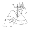
- a Darrieus turbine shown in FIG. 9 may be used.
- Such a Darrieus turbine shown in FIG. 9 may be used.
- Such a Darrieus turbine shown in FIG. 9 may be used.
- Such a Darrieus turbine shown in FIG. 9 may be used.
- a rotating body 300 that rotates in response to a tidal current F flowing from upstream to downstream in the sea, a power generator 400 that generates power based on the rotational force of the rotating body 300, and a tidal current F at a position lower than the rotating body 300 in the sea.
- a tidal current power generation apparatus comprising: induction devices 100 and 100B having inclined surfaces (a surface of the guiding portion 110, a surface of the guiding portion 110B) for guiding the tidal current F so that the air flows toward the rotating body 300. It is disclosed. Thereby, the flow of the tidal current F in the vicinity of the seabed B is changed in the inclination direction of the inclined surface, and the power generation efficiency of the tidal current power generation can be improved.
- the guidance devices 100 and 100B have a shape that widens from the downstream side toward the upstream side, and the inclined surfaces (a surface of the guidance portion 110 and a surface of the guidance portion 110B) are guidance devices. It may be formed on the surface facing the upstream side of 100, 100B. Thereby, the flow of the tidal current F near the seabed B can be changed in the horizontal direction, and the power generation efficiency of the tidal current power generation can be improved.
- the inclined surfaces are formed at least on the surface close to the downstream side among the surfaces facing the upstream side of the guiding devices 100 and 100B. Also good. Thereby, the flow of the tidal current F in the vicinity of the seabed B is changed in the inclination direction of the inclined surface, and the power generation efficiency of the tidal current power generation can be improved.
- the guidance devices 100 and 100B may exhibit a shape that expands in a V shape or a U shape from the downstream side toward the upstream side. Thereby, the flow of the tidal current F near the seabed B can be changed in the horizontal direction, and the power generation efficiency of the tidal current power generation can be improved.
- the rotating body 300 is disposed in a gap M between the first and second structures 200A and 200B that are disposed adjacent to each other in a direction (Y direction) intersecting the direction connecting the upstream side and the downstream side.
- the guidance devices 100 and 100B may be disposed such that the downstream end portion faces the gap M.
- first and second structures 200A and 200B may be piers that support a bridge on the sea.
- the guidance devices 100 and 100B can also prevent scouring the piers 200A and 200B.
- the guidance devices 100 and 100B may be disposed on the seabed B so as to be adjacent to the first and second structures 200A and 200B. Thereby, the guidance devices 100 and 100B can more effectively prevent scouring the piers 200A and 200B.
- both end portions 111 and 112 extending in the direction intersecting the direction connecting the upstream side and the downstream side of the guidance device 100 have a shape that goes from the upstream side to the downstream side as the distance from the gap M increases. May be.
- the tidal current F toward the piers 200A and 200B deviates from the direction toward the piers 200A and 200B, so that a strong downward flow is less likely to occur, and scouring the piers 200A and 200B more effectively. Can be prevented.
- the guidance device 100B includes two crest-shaped deposition portions 120B and 130B formed at positions upstream of the first and second structures 200A and 200B, and a space between the two deposition portions 120B and 130B. It may be constituted by a guide part 110B having an inclined surface a formed at a position.
- the two mountain-shaped accumulation portions 120B and 130B may be formed of coal ash granulated material.
- the guidance device 100B may be formed on the recesses B 'around the first and second structures 200A and 200B on the seabed B. As a result, scouring of the supporting ground for the piers 200A and 200B can be prevented, and the environmental load can be reduced.
Landscapes
- Engineering & Computer Science (AREA)
- Life Sciences & Earth Sciences (AREA)
- General Life Sciences & Earth Sciences (AREA)
- Oceanography (AREA)
- Chemical & Material Sciences (AREA)
- Combustion & Propulsion (AREA)
- Mechanical Engineering (AREA)
- General Engineering & Computer Science (AREA)
- Other Liquid Machine Or Engine Such As Wave Power Use (AREA)
- Hydraulic Turbines (AREA)
Abstract
【課題】 本発明は、潮流発電の発電効率を向上させるべく、海水の流れのエネルギーをより効率的に捕捉する潮流発電装置を提供することを目的とする。 【解決手段】 本発明の解決手段は、海中において上流側から下流側へ向かう潮流を受けて回転する回転体と、回転体の回転力に基づいて発電を行う発電装置と、海中の回転体よりも低い位置において潮流が回転体に向かうように潮流を誘導する傾斜面を有する誘導装置と、を備えることを特徴とする潮流発電装置である。
Description
本発明は、潮流発電装置に関する。
近年、世界規模でのエネルギー需要の拡大に伴い、化石燃料に代わるエネルギーとして、潮汐によって生じる海水の流れを利用して発電を行う潮流発電が注目されている(例えば、特許文献1を参照)。
潮流発電は、海水の流れ(潮流)を電気エネルギーに変換することから、如何に海水の流れのエネルギーを捕捉するかが、発電効率の向上に直結する。
そこで、本発明は、潮流発電の発電効率を向上させるべく、海水の流れのエネルギーをより効率的に捕捉する潮流発電装置を提供することを目的とする。
前述した課題を解決する主たる本発明は、海中において上流側から下流側へ向かう潮流を受けて回転する回転体と、前記回転体の回転力に基づいて発電を行う発電装置と、前記海中の前記回転体よりも低い位置において前記潮流が前記回転体に向かうように前記潮流を誘導する傾斜面を有する誘導装置と、を備えることを特徴とする潮流発電装置である。本発明の他の特徴については、添付図面及び本明細書の記載により明らかとなる。
本発明によれば、潮流発電の発電効率を向上させることができる。
本明細書および添付図面の記載により、少なくとも以下の事項が明らかとなる。
<第1実施形態>
===潮流発電装置の構成について===
本実施形態に係る潮流発電装置の構成の一例を、図1、図2、図3に示す。
<第1実施形態>
===潮流発電装置の構成について===
本実施形態に係る潮流発電装置の構成の一例を、図1、図2、図3に示す。
図1は潮流発電装置の斜視図、図2は潮流発電装置の平面図、図3は潮流発電装置の側面図を表す。尚、図中の矢印Fは、潮流の流れ方向を示す。又、図中において、Z軸は、海底Bと海面の間の高さ方向を示す軸であり、X軸は、潮流の流れ方向(上流側と下流側を結ぶ方向)を示す軸であり、Y軸は、X軸及びZ軸に対して直交する方向(上流側及び下流側を結ぶ方向とは交差する方向)を示す軸である。尚、以下の説明では、それぞれ単に「X方向」、「Y方向」、「Z方向」と表し、矢印の示す方向を+方向、矢印と逆の方向を-方向を表す。又、海底Bから海面へ向かう方向(+Z方向)を、位置関係として「高い」及び「上」と表す。
本実施形態に係る潮流発電装置は、海中に配設され、誘導装置100、橋脚200A、200B、回転体300、発電装置400とから構成される。そして、本実施形態に係る潮流発電装置は、誘導装置100と橋脚200A、200Bとで潮流の流れを変化させ、発電装置400の発電効率を向上させる設備である。
橋脚200A、200Bは、海上の橋を支持する基礎部であり、例えば、海底B下の埋設された領域から海面方向に伸びる円柱形状のコンクリート構造物である。そして、橋脚200Aと橋脚200Bは、Y方向に隣接して配設され、橋脚200Aと橋脚200Bの間にY方向に間隙Mを形成している。
回転体300は、発電装置400の前面部分に取り付けられた3つ板状体、及び後面部分に取り付けられた3つ板状体により構成されるプロペラである。そして、回転体300の前面部分及び後面部分の3つ板状体は、上流側から下流側へ向かう潮流Fを受けて回転して、発電装置400の筐体内に伸びる軸受に回転力を伝達する。尚、本実施形態に係る回転体300は、前面部分と後面部分にプロペラを有することにより、軸受の回転力を増大させている。
発電装置400は、回転体300の回転力に基づいて発電を行う発電機であり、例えば、永久磁石式発電機である。発電装置400は、回転体300により回転させられる軸受を、永久磁石により発生する磁界内に設置することで、軸受に巻いた導線に起電力を発生させ、発電を行っている。そして、発電装置400は、発電した電力をパワーコンディショナーにより所定の周波数の交流電力に変換して、送電線(図示せず)により、地上の変電所に送電している。
尚、発電装置400は、橋脚200Aに固定部材を介して固定されている。そして、発電装置400に取り付けられた回転体300は、橋脚200Aと橋脚200Bの間の間隙Mに設置されている。
誘導装置100は、回転体300に向けて潮流Fを誘導するとともに、橋脚200A、200Bに対する洗掘を防止する装置である。誘導装置100は、例えば、海底Bにコンクリートにより形成された1m程度の高さを有する堰である。そして、誘導装置100は、海底Bから立設する橋脚200A、200Bの上流側に、橋脚200A、200Bと隣接して配設されている。尚、本実施形態では、洗掘をより効果的に防止するため、誘導装置100と橋脚200A、200Bの潮流Fの流れ方向の間隔は、各隣接位置で橋脚200A、200Bの径Rよりも短い距離となっている。尚、誘導装置100と橋脚200A、200Bの潮流Fの流れ方向の間隔とは、図2中のH1、H2、H3、H4、H5で表すように、誘導装置100の下流側の面(図3中に示すb面)から潮流Fの流れ方向に橋脚200A、200Bの表面位置に直線を伸ばしたときの当該直線距離を意味する。
ここで、誘導装置100は、海底B付近の潮流Fを回転体300に向かって上昇するように誘導する誘導部110と、誘導部110から+Y方向に伸びる第1端部111、誘導部110から-Y方向に伸びる第2端部112により構成される。
誘導装置100の誘導部110は、上流側と対向する面に傾斜面(図3中に示すa面)を有するとともに、下流側から上流側へ向かうにつれて広がるV字型の形状を呈する。
誘導部110の傾斜面は、誘導装置100の上流側と対向する面に形成された面であり、当該傾斜方向の延長線上に回転体300が設置されるようにして、海底B付近の潮流Fを回転体300に向かうように誘導する。尚、傾斜方向の延長線上とは、略延長線上との意味であり、回転体300の位置で通過する水量が増加するようにとの意味である。尚、本実施形態では、洗掘をより効果的に防止するため、傾斜面(a面)は、例えば、海底Bに対して下流側に向かって略20~45度の角度(図3中に示すθ)で形成される。尚、誘導部110の潮流Fに対して下流側の面(図3中に示すb面)は、海底Bに対して上流側に向かって傾斜する形状を呈する。
又、誘導部110のV字型の形状も、潮流Fを回転体300に向かうように誘導するべく、下流側の先端部が、間隙Mに臨むように、すなわち回転体300の設置方向に臨むように配設されている。
誘導装置100の第1端部111は、誘導装置100の誘導部110から+Y方向に伸びる部分である。又、誘導装置100の第2端部112は、誘導装置100の誘導部110から-Y方向に伸びる部分である。そして、第1端部111及び第2端部112は、橋脚200A、200Bを洗掘から保護するべく、間隙Mから離れるにつれて上流側から下流側へ向かう形状を呈する。又、第1端部111及び第2端部112は、誘導部110と同様に、上流側と対向する面に、海底Bに対して下流側に上向く傾斜面を有している。
尚、本実施形態では、潮の満ち引きに応じて潮流Fの向きが逆向きとなることから、逆向きからの潮流に対する上流側の位置にも、同様の構造の誘導装置100’を配設している。すなわち、潮流は、満潮時には沖側から岸側に向かうが、干潮時には岸側から沖側に向かう。そのため、本実施形態に係る潮流発電装置は、満潮時の潮流Fに対応するべく誘導装置100を配設し、干潮時の潮流F’に対応するべく誘導装置100’を配設する。そして、誘導装置100’は、岸側から沖側に向かう潮流F’を回転体300に向かうように誘導する誘導部110’と、誘導部110’から+Y方向に伸びる第1端部111’、誘導部110’から-Y方向に伸びる第2端部112’により構成され、回転体300に向けて潮流F’を誘導するとともに、橋脚200A、200Bに対する洗掘を防止する(誘導装置100’は、誘導装置100と同様の構造であるから、以下、総称して「誘導装置100」と言う。尚、図1中では誘導装置100’を省略して表している。)。
尚、岸側から沖側に向かう潮流F’を発電に利用する場合、回転体300の水平方向の向きを潮流の方向に応じて自由に変更できる構成とする。例えば、回転体300及び発電装置400を水平方向(XY方向)に自由に旋回運動する基礎部で支持し、潮流の流れ方向の応力を利用して当該基礎部を旋回する構成とすればよい。
又、岸側から沖側に向かう潮流F’を発電に利用する他の方法として、岸側から沖側に向かう潮流F’となった場合は沖側から岸側に向かう潮流Fの場合と逆方向に回転する回転体300と、逆方向の回転によっても整流できるパワーコンディショナーを有する発電装置400により構成してもよい。この場合、上記の回転体300及び発電装置400を旋回させる構成は不要である。
尚、誘導装置100は、例えば、上記の形状に成形するための型枠を海底Bに配設し、当該型枠にノズルを介して生コンクリートを流し込み、海中で固化させることによって形成されている。
===潮流の流れ方向の変化について===
次に、図1、図2、図3を参照して、本実施形態に係る潮流発電装置による潮流の流れ方向の変化について説明する。
===潮流の流れ方向の変化について===
次に、図1、図2、図3を参照して、本実施形態に係る潮流発電装置による潮流の流れ方向の変化について説明する。
本実施形態に係る潮流発電装置では、誘導装置100と、橋脚200A、200Bによって、潮流Fの流れを変化させることで、回転体300が潮流Fのエネルギーを捕捉しやすくしている。
第1に、誘導装置100の誘導部110は、上流側と対向する面に傾斜面を有するとともに、下流側から上流側へ向かうにつれて広がるV字型を呈している。これにより、海底B付近の潮流Fは、傾斜面の傾斜方向へ誘導されることになる。又、海底B付近の潮流Fは、水平方向では、V字型の形状の収束する方向へ誘導されることになる。そのため、垂直方向及び水平方向から潮流Fが誘導され、当該誘導位置に配設された回転体300付近で流速を上昇させることができる。
第2に、回転体300は、橋脚200Aと橋脚200Bの間隙Mに配置されている。間隙Mでは流路が狭まることから、潮流Fの流速が上昇する。特に、本実施形態では、橋脚200Aと橋脚200Bは円柱形状をなすことから、間隙Mには潮流Fの流れ方向に向かって収束する領域(Y方向の間隔が狭くなっていく領域)が形成されているため、四角柱形状で形成されている場合に比して、流速を上昇させることができる。
又、本実施形態に係る潮流発電装置では、誘導装置100によって、橋脚200A、橋脚200Bの海底B付近の潮流Fの流れを変化させることで、橋脚200A及び橋脚200Bの付近における洗掘を防止している。
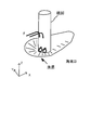
一般に、橋脚の洗掘は、図4に示すように、橋脚に衝突した潮流が下降流及び渦流を生み、これが海底の砂礫を巻き上げ、砂礫が押し流されることによって生じる。
この点、本実施形態によれば、第1に、誘導装置100の誘導部110は下流側の先端部が間隙Mに臨むV字型の形状を呈するとともに、第1端部111及び第2端部112は間隙Mから離れるにつれて、上流側から下流側へ向かう形状を呈する。これにより、橋脚200A、200Bへ向かう潮流Fは、流れ方向が橋脚200A、200Bへ向かう方向から外れることになり、強力な下降流が発生にくくなる。
第2に、誘導装置100の誘導部110、第1端部111、第2端部112は、下流側に上向く傾斜面により上方向に向かう潮流Fを生じさせ、橋脚200A、200Bの上層で衝突した潮流Fの下降流を相殺する。すなわち、誘導装置100と橋脚200A、200Bとの間の領域は、よどみ点となる。
以上、本実施形態に係る潮流発電装置によれば、潮流の流れを変化させることで、潮流発電の発電効率を向上させるとともに、及び橋脚に対する洗掘を防止することができる。
尚、上記実施形態では、誘導装置100の誘導部110の傾斜面の傾斜角を海底Bから略20~45度の角度とし、誘導装置100と橋脚200A、200Bの間の流れ方向の間隔を橋脚200A、200Bの径Rよりも短い距離となるように配設した。この条件を満たす場合、上方向に向かう潮流Fにより、橋脚200A、200Bの上層で衝突した潮流Fの下降流を相殺しやすいため、洗掘防止の観点では望ましいが、潮流Fを回転体300に向けて誘導しやすいように設計変更してもよい。
尚、上記実施形態では、誘導装置100をコンクリートにより形成する態様を示したが、その材料は任意であり、例えば、外形が誘導装置100の形状となった金網に石を詰めて構成してもよい。又、複数個の部材を海底Bに設置して、誘導装置100の形状を成形してもよい。
又、上記実施形態では、潮の満ち引きに応じて潮流Fの向きが逆向きとなることから、誘導装置100、誘導装置100’を配設する態様とした。しかし、潮流Fの流れが、一方向のみ強い場合であれば、一方向のみに対応する誘導装置100を配設するものであってもよい。
又、上記実施形態では、誘導装置100の誘導部110を上流側と対向する面に海底Bから下流側へ傾斜する傾斜面を備え、下流側から上流側へ向かうにつれてV字型に広がる形状を呈する態様を示した。しかし、誘導部110の形状は、潮流Fを効率的に回転体300に向かうように誘導することができれば、他の形状であってもよい。例えば、下流側から上流側へ向かうにつれてU字型に広がる形状であってもよい。又、誘導部110の上流側と対向する側のみに下流側から上流側へ向かうにつれてV字型に広がる形状を呈するものであってもよい。
<第2実施形態>
本実施形態に係る潮流発電装置は、粒状物の堆積により誘導装置100Bを形成する点で、第1実施形態と異なっている。本実施形態によれば、第1実施形態と同様に潮流の流れ方向に変化を起こし、第1実施形態と同様の効果を得ることができることに加え、橋脚200A、200Bを配設する支持地盤の洗掘を防止できること、及び環境負荷を低減できることから有用である。尚、第1実施形態と共通する構成については説明を省略する。
<第2実施形態>
本実施形態に係る潮流発電装置は、粒状物の堆積により誘導装置100Bを形成する点で、第1実施形態と異なっている。本実施形態によれば、第1実施形態と同様に潮流の流れ方向に変化を起こし、第1実施形態と同様の効果を得ることができることに加え、橋脚200A、200Bを配設する支持地盤の洗掘を防止できること、及び環境負荷を低減できることから有用である。尚、第1実施形態と共通する構成については説明を省略する。
本実施形態に係る潮流発電装置の構成の一例を、図5、図6、図7に示す。尚、図5は潮流発電装置の斜視図、図6は潮流発電装置を海面方向から見た平面図、図7は潮流発電装置を発電装置の位置から見た側面図を表す。
本実施形態に係る潮流発電装置は、誘導装置100B、橋脚200A、200B、回転体300、発電装置400とから構成される。そして、橋脚200A、200B、回転体300、発電装置400の構成は、第1実施形態と同様である。
一方、本実施形態に係る誘導装置100Bは、粒径20mm程度の粒状物、例えば、石炭灰造粒物が堆積されることにより形成される。
石炭灰造粒物とは、石炭を燃焼することで産出される石炭灰(フライアッシュ)に、セメント、水を混合して撹拌等することにより形成された石炭灰を主成分とする粒状物である。
石炭灰造粒物は、粒径を大きくすることが可能であることに加えて、天然の砂以上のせん断強さ、粘着度を有するため、すべりが生じにくい。又、石炭灰造粒物は、高い強度を有し、盛土材等に用いられても安定した土壌を形成できる。又、石炭灰造粒物は、石炭灰が主成分となっていることから、海底の蓄積されたリンを固形化して水中に溶出するのを防止する水質改善効果も有し、海中にコンクリートの構造物を形成するよりも、環境負荷が少ない。そこで、本実施形態では、石炭灰造粒物を用いて誘導装置100Bを形成することにより、支持地盤の洗掘防止及び環境負荷の低減を図る。
本実施形態に係る誘導装置100Bは、海底Bに配設され、誘導部110B、第1堆積部120B、第2堆積部130Bにより構成される。尚、図6の囲み線T1、T2、T3、T4、T5、T6は、海底Bに粒状物を堆積することにより形成された誘導装置100Bの等高線を表す。すなわち、囲み線T1が最も高い位置を表し、高い順に囲み線T2、T3、T4、T5、T6と表している。
第1堆積部120B、第2堆積部130Bは、それぞれ橋脚200A、橋脚200Bの上流側の手前位置に配設された山なりの形状の粒状物の山である。第1堆積部120B、第2堆積部130Bは、それぞれの頂点位置付近に、粒状物を集中的に投下することによって形成される。
又、第1堆積部120B、第2堆積部130Bの底面の直径N2は、略同一となるように形成されている。又、第1堆積部120B、第2堆積部130Bの底面の直径N2は、橋脚200A、橋脚200Bに対する洗掘を防止するべく、橋脚200A、橋脚200Bの径Rよりも大きくなるように形成されている。尚、第1堆積部120B、第2堆積部130Bの底面の直径N2とは、山なりの形状の頂点位置から山なりの傾斜方向に伸ばした線分と海底Bの交わる位置を底面としたときに形成される略円形状の直径である。
又、第1堆積部120B、第2堆積部130Bの間の領域に誘導部110Bが形成されるように、第1堆積部120Bの頂点と第2堆積部130Bの頂点の間の距離N1は、第1堆積部120B及び第2堆積部130Bの山なりの形状の底面の直径N2の2倍以下となるようにしている。誘導部110Bは、山なりの形状の第1堆積部120Bと第2堆積部130Bを形成する際に、第1堆積部120Bと第2堆積部130Bの間の領域、すなわち山と山が交わる領域に形成される。そして、誘導部110Bの上流側と対向する面に、潮流Fを回転体300に誘導するように傾斜面(図7中のa面)が形成されている。尚、誘導部110Bの形成方法の一例は後述するが、粒状物で第1堆積部120Bを形成する際に生じる崩落と、粒状物で第2堆積部130Bを形成する際に生じる崩落により、結果的に傾斜面を有する誘導部110Bが形成される。
このとき、粒状物の雪崩れにより形成される誘導部110Bは、上流と対向する側に、図6中のU線で示すように、第1堆積部120Bの等高線T3と、第2堆積部130Bの等高線T3との間の領域を高さ位置の頂点として、下流側へ上向く傾斜面を形成する。そして、誘導部110Bは、水平方向において下流側から上流側に向かってU字型に広がる形状を呈している。又、誘導部110BのU字型の形状の下流側の先端部は、間隙Mに臨むように配設される。
又、誘導装置100Bは、海底Bに形成された凹部B’の上に形成される(図6中の囲み線T6は、凹部B’の溝形状を表す。)。
尚、海底Bに形成された凹部B’は、橋脚200A、200Bを配設する支持地盤を露出するため、海底Bの表層の軟質層を掘削して形成された橋脚200A、橋脚200Bを配設する位置の周囲に形成された溝である(図6、図7を参照)。尚、図5では、凹部B’を省略して表している。
そして、本実施形態では、凹部B’の上に粒状物を堆積することによって、支持地盤の底質材の吸出し防止のフィルターの役割を果たすことで、橋脚200A、200B付近の洗掘を防止する。従って、粒状物の粒径は、既知のフィルター理論に基づいて、支持地盤の底質材の粒径の3~5倍と設定するのが望ましい。又、粒状物自体が潮流により流れ出すのを防止するため、粒径が10mm以上のものを使用するのが望ましい。
又、本実施形態に係る潮流発電装置も、第1実施形態と同様に、橋脚200A、200Bの逆向きの潮流に対する手前位置に、同様の構造の誘導装置100B’を配設している(図5中では誘導装置100B’を省略して表している)。
ここで、図8を参照して、誘導装置100Bを形成する工程の一例について説明する。
始めに、橋脚200A、200Bを配設する位置の海底Bの軟質層を掘削し支持地盤となる層が露出されるように凹部B’を形成する。
そして、凹部B’に海面上に突出する高さの橋脚200A及び橋脚200B形成用のケーソンKを立設する。
ケーソンKを立設した後、粒径20mm程度の石炭灰造粒物を凹部B’に埋設するように誘導装置100Bの第1堆積部120B、第2堆積部130Bを形成する。ここで、石炭灰造粒物の投下は、例えば、石炭灰造粒物をバケットLに入れて、海上の資材台船PからバケットLを海面下に投下することにより行う。又、このとき、凹部B’に石炭灰造粒物を投下することにより、凹部B’を埋設し、支持地盤の底質材を露出させないようにする。
そして、バケットLからノズルを介して、第1堆積部120B及び第2堆積部130Bの頂点とすべき位置の付近で集中的に石炭灰造粒物を投下することにより、山なりの形状の第1堆積部120B及び第2堆積部130Bを形成することができる。
具体的には、石炭灰造粒物を海面下に投下したとき、石炭灰造粒物の重力と石炭灰造粒物間の摩擦力の関係に基づいて、第1堆積部120B、第2堆積部130Bの頂点位置から周囲に崩落が生じることで、略山なりの形状の第1堆積部120B及び第2堆積部130Bが形成される。又、第1堆積部120Bと第2堆積部130Bの間の領域には、第1堆積部120Bを形成したときに生じる崩落と第2堆積部130Bを形成したときに生じる崩落とにより、傾斜面を有する誘導部110Bが形成される。
その後、ケーソンKに生コンクリートを供給し固化することで、橋脚200A、200Bを形成している。尚、橋脚200A、200Bの形成方法は、周知のケーソン施工によるため詳細は省略する。
以上、本実施形態に係る潮流発電装置によれば、潮流の流れを変化させることで、潮流発電の発電効率の向上、及び橋脚に対する洗掘を防止することができる。
又、橋脚を配設する支持地盤に石炭灰造粒物を堆積させるため、支持地盤の洗掘防止の機能も向上させることができる。又、石炭灰造粒物を用いることにより、コンクリートを海中に形成することによる環境負荷を低減するとともに、水質を改善することができる。
尚、上記実施形態では、支持地盤となる層の凹部B’にケーソンKを立設した後、石炭灰造粒物を埋設した。しかし、これに代えて、凹部B’に石炭灰造粒物を埋設した後、ケーソンKを立設する態様であってもよい。石炭灰造粒物は、高い一軸圧縮強さも有しているため、この場合、ケーソンKの下地の支持地盤を強化することもできる。
<その他の実施形態>
尚、上記実施形態では、発電装置400を橋脚200Aに取り付ける態様を示したが、発電装置400を配設する態様は任意である。例えば、橋脚200A、200Bとは独立して海底Bに配設してもよいし、海面にフロートさせて配設してもよい。
<その他の実施形態>
尚、上記実施形態では、発電装置400を橋脚200Aに取り付ける態様を示したが、発電装置400を配設する態様は任意である。例えば、橋脚200A、200Bとは独立して海底Bに配設してもよいし、海面にフロートさせて配設してもよい。
又、上記実施形態では、回転体300を橋脚200A、200Bの間隙Mに設置する態様を示したが、必ずしも橋脚200A、200Bの間隙Mに設置する必要はない。すなわち、本発明に係る潮流発電装置は、誘導装置100、100B、回転体300、発電装置400のみから構成されてもよい。この場合であっても、回転体300付近の潮流Fの流速を上昇させ、潮流発電の発電効率を向上させることができる。
又、上記実施形態では、回転体300の構造を発電装置400の前面及び後面に取り付けられる3本の板状体から構成される態様を示したが、回転体300の構造は、任意である。例えば、図9に示すダリウス水車を用いてもよい。
===結言===
以上より、上記各実施形態は、次のように記載できる。
===結言===
以上より、上記各実施形態は、次のように記載できる。
海中において上流側から下流側へ向かう潮流Fを受けて回転する回転体300と、回転体300の回転力に基づいて発電を行う発電装置400と、海中の回転体300よりも低い位置において潮流Fが回転体300に向かうように潮流Fを誘導する傾斜面(誘導部110のa面、誘導部110Bのa面)を有する誘導装置100、100Bと、を備えることを特徴とする潮流発電装置を開示するものである。これによって、傾斜面の傾斜方向に海底B付近の潮流Fの流れを変化させ、潮流発電の発電効率を向上させることができる。
ここで、誘導装置100、100B(誘導部110、110B)は、下流側から上流側へ向かうにつれて広がる形状を呈し、傾斜面(誘導部110のa面、誘導部110Bのa面)は誘導装置100、100Bの上流側と対向する面に形成されるものであってもよい。これによって、水平方向に海底B付近の潮流Fの流れを変化させ、潮流発電の発電効率を向上させることができる。
又、傾斜面(誘導部110のa面、誘導部110Bのa面)は、誘導装置100、100Bの上流側と対向する面のうち、少なくとも下流側に近い面に形成されるものであってもよい。これによって、傾斜面の傾斜方向に海底B付近の潮流Fの流れを変化させ、潮流発電の発電効率を向上させることができる。
又、誘導装置100、100B(誘導部110、110B)は、下流側から上流側へ向かうにつれてV字型又はU字型に広がる形状を呈するものであってもよい。これによって、水平方向に海底B付近の潮流Fの流れを変化させ、潮流発電の発電効率を向上させることができる。
又、回転体300は、上流側及び下流側を結ぶ方向とは交差する方向(Y方向)において隣接して配設される第1及び第2構造物200A、200Bの間の間隙Mに配設され、誘導装置100、100B(誘導部110、110B)は、下流側の先端部が間隙Mに臨むように配設されてもよい。これによって、水平方向に海底B付近の潮流Fの流速を上昇させ、潮流発電の発電効率を向上させることができる。
又、第1及び第2構造物200A、200Bは、海上の橋を支持する橋脚であってもよい。これによって、誘導装置100、100Bは、橋脚200A、200Bに対する洗掘も防止することができる。
又、誘導装置100、100Bは、第1及び第2構造物200A、200Bと隣接するように海底Bに配設されてもよい。これによって、誘導装置100、100Bは、橋脚200A、200Bに対する洗掘をより効果的に防止することができる。
又、誘導装置100の上流側及び下流側を結ぶ方向と交差する方向(Y方向)に伸びる両端部111、112は、間隙Mから離れるにつれて、上流側から下流側へ向かう形状を呈するものであってもよい。これによって、橋脚200A、200Bへ向かう潮流Fは、流れ方向が橋脚200A、200Bへ向かう方向から外れることになり、強力な下降流が発生にくくなり、橋脚200A、200Bに対する洗掘をより効果的に防止することができる。
又、誘導装置100Bは、第1及び第2構造物200A、200B各々の上流側の位置に形成された二つの山なり形状の堆積部120B、130Bと、二つの堆積部120B、130Bの間の位置に形成された傾斜面aを有する誘導部110Bとにより構成されるものであってもよい。
又、二つの山なりの形状の堆積部120B、130Bは、石炭灰造粒物によって形成されるものであってもよい。
又、誘導装置100Bは、海底Bの第1及び第2構造物200A、200Bの周囲の凹部B’の上に形成されてもよい。これによって、橋脚200A、200Bの支持地盤の洗掘を防止することができるとともに、環境負荷を低減することができる。
以上、本発明の具体例を詳細に説明したが、これらは例示にすぎず、請求の範囲を限定するものではない。請求の範囲に記載の技術には、以上に例示した具体例を様々に変形、変更したものが含まれる。
100、100B…誘導装置
110、110B…誘導部
111…第1端部
112…第2端部
120B…第1堆積部
130B…第2堆積部
200A、200B…橋脚
300…回転体
400…発電装置
F…潮流
B…海底
B’…凹部
M…間隙
110、110B…誘導部
111…第1端部
112…第2端部
120B…第1堆積部
130B…第2堆積部
200A、200B…橋脚
300…回転体
400…発電装置
F…潮流
B…海底
B’…凹部
M…間隙
Claims (11)
- 海中において上流側から下流側へ向かう潮流を受けて回転する回転体と、
前記回転体の回転力に基づいて発電を行う発電装置と、
前記海中の前記回転体よりも低い位置において前記潮流が前記回転体に向かうように前記潮流を誘導する傾斜面を有する誘導装置と、
を備えることを特徴とする潮流発電装置。 - 前記誘導装置は、下流側から上流側へ向かうにつれて広がる形状を呈し、前記傾斜面は、前記誘導装置の上流側と対向する面に形成される
ことを特徴とする請求項1に記載の潮流発電装置。 - 前記傾斜面は、前記誘導装置の上流側と対向する面のうち、少なくとも下流側に近い面に形成される
ことを特徴とする請求項1又2に記載の潮流発電装置。 - 前記誘導装置は、下流側から上流側へ向かうにつれてV字型又はU字型に広がる形状を呈する
ことを特徴とする請求項1乃至3いずれか一項に記載の潮流発電装置。 - 前記回転体は、上流側及び下流側を結ぶ方向とは交差する方向において隣接して配設される第1及び第2構造物の間の間隙に配設され、
前記誘導装置は、下流側の先端部が前記間隙に臨むように配設される
ことを特徴とする請求項1乃至4いずれか一項に記載の潮流発電装置。 - 前記第1及び第2構造物は、海上の橋を支持する橋脚である
ことを特徴とする請求項5に記載の潮流発電装置。 - 前記誘導装置は、前記第1及び第2構造物と隣接するように海底に配設される
ことを特徴とする請求項5又は6に記載の潮流発電装置。 - 前記誘導装置の上流側及び下流側を結ぶ方向と交差する方向に伸びる両端部は、前記間隙から離れるにつれて、上流側から下流側へ向かう形状を呈する
ことを特徴とする請求項7に記載の潮流発電装置。 - 前記誘導装置は、前記第1及び第2構造物各々の上流側の位置に形成された二つの山なり形状の堆積部と、前記二つの堆積部の間の位置に形成された前記傾斜面を有する誘導部と、を備える
ことを特徴とする請求項7に記載の潮流発電装置。 - 前記二つの山なりの形状の堆積部は、石炭灰造粒物により形成される
ことを特徴とする請求項9に記載の潮流発電装置。 - 前記誘導装置は、海底の前記第1及び第2構造物の周囲の凹部の上に形成される
ことを特徴とする請求項9又は10に記載の潮流発電装置。
Priority Applications (2)
| Application Number | Priority Date | Filing Date | Title |
|---|---|---|---|
| PCT/JP2015/052710 WO2016121109A1 (ja) | 2015-01-30 | 2015-01-30 | 潮流発電装置 |
| JP2016540063A JP6090540B2 (ja) | 2015-01-30 | 2015-01-30 | 潮流発電装置 |
Applications Claiming Priority (1)
| Application Number | Priority Date | Filing Date | Title |
|---|---|---|---|
| PCT/JP2015/052710 WO2016121109A1 (ja) | 2015-01-30 | 2015-01-30 | 潮流発電装置 |
Publications (1)
| Publication Number | Publication Date |
|---|---|
| WO2016121109A1 true WO2016121109A1 (ja) | 2016-08-04 |
Family
ID=56542759
Family Applications (1)
| Application Number | Title | Priority Date | Filing Date |
|---|---|---|---|
| PCT/JP2015/052710 Ceased WO2016121109A1 (ja) | 2015-01-30 | 2015-01-30 | 潮流発電装置 |
Country Status (2)
| Country | Link |
|---|---|
| JP (1) | JP6090540B2 (ja) |
| WO (1) | WO2016121109A1 (ja) |
Cited By (1)
| Publication number | Priority date | Publication date | Assignee | Title |
|---|---|---|---|---|
| JP2021134680A (ja) * | 2020-02-25 | 2021-09-13 | 雅人 斉藤 | 誘水式潮流発電装置 |
Citations (5)
| Publication number | Priority date | Publication date | Assignee | Title |
|---|---|---|---|---|
| JPS5376245A (en) * | 1976-12-18 | 1978-07-06 | Tooru Fujii | Generator apparatus with front and reverse flows accelerator |
| US4383797A (en) * | 1979-07-16 | 1983-05-17 | Lee Edmund M | Underwater turbine device with hinged collapsible blades |
| JP2005214142A (ja) * | 2004-01-30 | 2005-08-11 | Mitsubishi Heavy Ind Ltd | 発電装置 |
| WO2009033232A1 (en) * | 2007-09-14 | 2009-03-19 | Atlantis Resources Corporation Pte Limited | Reversible turbine deployment system and apparatus, especially for reversible water current and tidal flows |
| WO2013116899A1 (en) * | 2012-02-06 | 2013-08-15 | Hermatika Pty Ltd | Electricity generating apparatus |
-
2015
- 2015-01-30 JP JP2016540063A patent/JP6090540B2/ja active Active
- 2015-01-30 WO PCT/JP2015/052710 patent/WO2016121109A1/ja not_active Ceased
Patent Citations (5)
| Publication number | Priority date | Publication date | Assignee | Title |
|---|---|---|---|---|
| JPS5376245A (en) * | 1976-12-18 | 1978-07-06 | Tooru Fujii | Generator apparatus with front and reverse flows accelerator |
| US4383797A (en) * | 1979-07-16 | 1983-05-17 | Lee Edmund M | Underwater turbine device with hinged collapsible blades |
| JP2005214142A (ja) * | 2004-01-30 | 2005-08-11 | Mitsubishi Heavy Ind Ltd | 発電装置 |
| WO2009033232A1 (en) * | 2007-09-14 | 2009-03-19 | Atlantis Resources Corporation Pte Limited | Reversible turbine deployment system and apparatus, especially for reversible water current and tidal flows |
| WO2013116899A1 (en) * | 2012-02-06 | 2013-08-15 | Hermatika Pty Ltd | Electricity generating apparatus |
Cited By (1)
| Publication number | Priority date | Publication date | Assignee | Title |
|---|---|---|---|---|
| JP2021134680A (ja) * | 2020-02-25 | 2021-09-13 | 雅人 斉藤 | 誘水式潮流発電装置 |
Also Published As
| Publication number | Publication date |
|---|---|
| JP6090540B2 (ja) | 2017-03-08 |
| JPWO2016121109A1 (ja) | 2017-04-27 |
Similar Documents
| Publication | Publication Date | Title |
|---|---|---|
| JP2021510793A (ja) | 風力および太陽光発電のためのマルチ風力タービンおよびソーラーを支持する風に対向して自己整列する浮体式プラットフォーム、ならびにその構築方法 | |
| KR100900500B1 (ko) | 넓은 분산 부유 구조물을 가진 해상 부유 풍력 발전 장치 | |
| JP4787286B2 (ja) | 水力発電装置 | |
| CN204040050U (zh) | 混合型海上风电基础结构 | |
| CN105917113A (zh) | 用于布置所谓的“海洋”抽水蓄能水力发电站的方法和相应的发电站 | |
| JP4856134B2 (ja) | 水力発電装置 | |
| JP6090540B2 (ja) | 潮流発電装置 | |
| US20160356262A1 (en) | Modular hydrokinetic turbine | |
| JP6001732B1 (ja) | 流体利用による双安定型非線形振り子発電機 | |
| KR20150031795A (ko) | 부유식 해상풍력발전기 하부구조물의 진동 안정화 장치 | |
| KR20110093308A (ko) | 교각의 충돌방지 구조물을 이용한 조류발전장치 및 그 시공방법 | |
| JP6286193B2 (ja) | 護岸構造 | |
| JP4669899B2 (ja) | 水流加速用の構築体 | |
| JP3197382U (ja) | 水上浮体構造物 | |
| CN206655244U (zh) | 防冲刷的仿生草结构及海上风机基础防冲刷保护装置 | |
| JP2557979B2 (ja) | 人工上昇流の形成方法 | |
| JP5342048B1 (ja) | 離岸式海中防波堤 | |
| JP2011144589A (ja) | 水中設置構造物およびこれを備える水中設置構造物群 | |
| CN206844177U (zh) | 海上风机基础防冲刷保护装置及其系统 | |
| Pu et al. | Self-burial and potential hazards of a submarine pipeline in the sand wave area in the South China Sea | |
| JP2008267103A (ja) | 海岸の侵食防止方法及びそれに使用する護岸ブロック | |
| JP2016069983A (ja) | 海洋深層水取水配管の支持方法 | |
| KR101109557B1 (ko) | 부류식 수력발전장치 | |
| KR101360283B1 (ko) | 해상용 풍력발전장치의 설치구조 | |
| KR101720383B1 (ko) | 다기능 바디선 |
Legal Events
| Date | Code | Title | Description |
|---|---|---|---|
| ENP | Entry into the national phase |
Ref document number: 2016540063 Country of ref document: JP Kind code of ref document: A |
|
| 121 | Ep: the epo has been informed by wipo that ep was designated in this application |
Ref document number: 15880006 Country of ref document: EP Kind code of ref document: A1 |
|
| NENP | Non-entry into the national phase |
Ref country code: DE |
|
| 122 | Ep: pct application non-entry in european phase |
Ref document number: 15880006 Country of ref document: EP Kind code of ref document: A1 |