WO2016120144A1 - Device for dispensing a liquid product - Google Patents
Device for dispensing a liquid product Download PDFInfo
- Publication number
- WO2016120144A1 WO2016120144A1 PCT/EP2016/051194 EP2016051194W WO2016120144A1 WO 2016120144 A1 WO2016120144 A1 WO 2016120144A1 EP 2016051194 W EP2016051194 W EP 2016051194W WO 2016120144 A1 WO2016120144 A1 WO 2016120144A1
- Authority
- WO
- WIPO (PCT)
- Prior art keywords
- sprayer
- bottle
- liquid product
- recess
- cavity
- Prior art date
Links
Images


Classifications
-
- B—PERFORMING OPERATIONS; TRANSPORTING
- B05—SPRAYING OR ATOMISING IN GENERAL; APPLYING FLUENT MATERIALS TO SURFACES, IN GENERAL
- B05B—SPRAYING APPARATUS; ATOMISING APPARATUS; NOZZLES
- B05B11/00—Single-unit hand-held apparatus in which flow of contents is produced by the muscular force of the operator at the moment of use
- B05B11/0005—Components or details
- B05B11/0037—Containers
- B05B11/0056—Containers with an additional opening for filling or refilling
-
- B—PERFORMING OPERATIONS; TRANSPORTING
- B05—SPRAYING OR ATOMISING IN GENERAL; APPLYING FLUENT MATERIALS TO SURFACES, IN GENERAL
- B05B—SPRAYING APPARATUS; ATOMISING APPARATUS; NOZZLES
- B05B11/00—Single-unit hand-held apparatus in which flow of contents is produced by the muscular force of the operator at the moment of use
- B05B11/0005—Components or details
- B05B11/0089—Dispensing tubes
- B05B11/0091—Dispensing tubes movable, e.g. articulated on the sprayer
- B05B11/0094—Dispensing tubes movable, e.g. articulated on the sprayer movement of the dispensing tube controlling a valve
-
- B—PERFORMING OPERATIONS; TRANSPORTING
- B05—SPRAYING OR ATOMISING IN GENERAL; APPLYING FLUENT MATERIALS TO SURFACES, IN GENERAL
- B05B—SPRAYING APPARATUS; ATOMISING APPARATUS; NOZZLES
- B05B11/00—Single-unit hand-held apparatus in which flow of contents is produced by the muscular force of the operator at the moment of use
- B05B11/01—Single-unit hand-held apparatus in which flow of contents is produced by the muscular force of the operator at the moment of use characterised by the means producing the flow
- B05B11/04—Deformable containers producing the flow, e.g. squeeze bottles
-
- B—PERFORMING OPERATIONS; TRANSPORTING
- B05—SPRAYING OR ATOMISING IN GENERAL; APPLYING FLUENT MATERIALS TO SURFACES, IN GENERAL
- B05B—SPRAYING APPARATUS; ATOMISING APPARATUS; NOZZLES
- B05B11/00—Single-unit hand-held apparatus in which flow of contents is produced by the muscular force of the operator at the moment of use
- B05B11/01—Single-unit hand-held apparatus in which flow of contents is produced by the muscular force of the operator at the moment of use characterised by the means producing the flow
- B05B11/10—Pump arrangements for transferring the contents from the container to a pump chamber by a sucking effect and forcing the contents out through the dispensing nozzle
- B05B11/1028—Pumps having a pumping chamber with a deformable wall
- B05B11/1032—Pumps having a pumping chamber with a deformable wall actuated without substantial movement of the nozzle in the direction of the pressure stroke
Definitions
- the present invention relates to a device for dispensing a toilet product or an industrial product in liquid form, in particular of the type comprising a bottle or a bottle having a separable and rechargeable sprayer.
- a device of the type mentioned, for example, by the published patent application GB-A-2 485 196 is known.
- This prior device comprises a container containing a liquid product, particularly a perfume, under pressure, and having a disconnectable segment. and which is arranged to be connected to the container so that the contents of the container can automatically pass into the segment through a fill valve, to reload the segment.
- the rechargeable segment also provides the sprayer for spraying the liquid product.
- the container in use having an internal pressure greater than the segment, and said segment is filled when connected.
- an air release mechanism is provided for the segment, before filling the segment with the contents again. of the container.
- the device with such mechanism does not return the liquid product segment in the container.
- the invention relates to a device for dispensing a liquid product, comprising a liquid product bottle having a separable and rechargeable sprayer provided with a type of spray pump with or without air intake, characterized in that the sprayer comprises a body defining a cavity, which is adapted to be filled, at least in part, with the liquid product from the bottle, the body defining a cavity comprising opposite end walls and at a distance one of the other connected by peripheral walls, and communicating with the interior of the bottle via a tubular element which can be received in a tubing of the bottle, the end walls remote from one of the other body of the sprayer being flexible, in order to move towards each other under the pressure of the fingers or as a result of a depression created inside the cavity, and being elastic, for a return movement after the pressure of the fingers is relaxed or when said depression becomes zero, so that the vacuum created by compression of the end walls of the body of the sprayer or by depression induces the suction liquid product of the bottle in the sprayer and compression of said end walls of the sprayer body
- the tubular element is rotatably connected to the body of the sprayer so that it can be turned by the user between a lowered operating position and a raised non-operative position, in which the tubular element is received inside the a recess in the peripheral walls of the sprayer body and closes a passage communicating with the cavity of the sprayer body;
- the bottle is provided with a recess for housing the sprayer in a detachable manner
- the spray pump being operable by means of a spray button to cause the liquid product to be dispensed through a nozzle;
- the liquid product in the bottle can be dispensed by the sprayer when it is housed in the chamber of the bottle;
- the bottle is provided with a separate dispensing mechanism, comprising a spray button and a nozzle, which allows to distribute the liquid product when the sprayer is detached from the bottle.
- FIGS. 1 and 2 are perspective views of the device comprising the features of the present invention.
- Figures 3 and 4 are illustrative views showing how the device according to the invention is used.
- numeral 10 represents a bottle or bottle for containing a liquid product, which is shown in gray, at the bottom portion of the bottle.
- This bottle 10 is provided with a refillable sprayer 11, which is arranged to be detachably housed in a recess 12 preferably disposed at the upper part of the body of the bottle 10.
- Appropriate staples may be provided on the sprayer 11 or in the recess region 12 to removably fix the sprayer 11 in the recess 12.
- the sprayer 11 has a body which is prismatic in shape and has opposite end walls 13 at a distance from each other (only the front end face is shown in the figures) and the peripheral walls 14 connecting the walls. 13 opposite ends.
- the sprayer body forms a cavity, which is adapted to be at least partially filled with the liquid product from the bottle 10. This cavity in the sprayer body communicates with a tubular valve member 15, wherein the product liquid can pass.
- the tubular member is rotatably connected to the sprayer body so that it can be rotated by the user between a lowered operative position, as shown in FIG. 2, and a raised non-operative position. wherein the tubular member is received within a suitable recess 16 of the lower peripheral walls 14 of the sprayer body, as shown in FIG. 1, and closes a passageway leading to the cavity of the sprayer body.
- a tubing 17 is provided inside the body of the bottle 10, to allow the passage of the liquid product between the bottle 10 and the sprayer 11.
- An end portion of the tubing 17 is submerged in the liquid contained in the body of the bottle 10 and the opposite end portion of the tubing 17 leads to an opening 18 at the bottom of the recess 12 and is adapted to be received within the tubular element of the sprayer 11.
- This opening 18 can be conveniently provided with a removable cap (not shown) or other sealing means, capable of providing a seal, when the sprayer 11 is removed from the recess 12.
- the end walls 13 of the sprayer body which are normally spaced apart from each other, are made of a flexible and flexible material so that they can move toward each other under the pressure of the fingers. or following a depression created inside the cavity, and to make a return movement, when the pressure of the fingers is released or said depression becomes zero.
- the peripheral walls 14 of the sprayer body are however in a rigid material, since they do not have to be flexible and elastic. The design details and materials used for the end walls 13 and the peripheral walls 14 may vary.
- the user In order to cause the passage of the liquid product in the sprayer 11, assuming that it does not contain the liquid product as shown in Figure 1, the user must remove the sprayer 11 from its chamber 12 of the bottle 10 and put the tubular member in the lowered operative position, as shown in FIG. 2. Then, the user presses the sprayer 11 into the region of the end walls 13 of the sprayer body to expel the air at the same time. the interior of the sprayer body by the tubular member, thereby creating a vacuum within the cavity of the sprayer body. While keeping the body of the sprayer compressed by finger pressure, the user then returns the sprayer 11 to its chamber 12 and, in doing so, inserts the tubular element completely into the open end of the tubing 17. At this point, the user can release finger pressure.
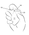
- the sprayer 11 is provided with a spray button 19, preferably placed on the upper peripheral wall 14 of the sprayer body.
- This spray button 19 operates a spray pump inside the sprayer 11, so that the liquid product is sprayed through a suitable spray nozzle, preferably placed on one of the end walls 13.
- This spray pump can be of the type with or without air intake.
- the sprayer is filled through a suitable filling valve (not shown) which is in sealed communication with a collection tube of the bottle 10 separate from the tubing 17.
- a suitable filling valve not shown
- the user does not need to compress the sprayer 11 to expel the air inside the body of the sprayer after the first filling and use, since the depression created inside the body of the sprayer induces the suction of the liquid product contained in the bottle 10 in the subsequent filling.
- the deformation of the flexible walls caused by the depression inside the sprayer cavity indicates to the user when the liquid product is at an end.
- An important aspect of the invention is that it allows the user to return the unused liquid product from the sprayer 11 to the bottle 10 through the tubular member. This can be done as follows. First, the user places the tubular member in the lowered operative position and returns the sprayer 11 into its recess 12 of the bottle 10, so that the tubular member is inserted over a substantial portion of its length into the tubing 17. Then, the user compresses the sprayer 11 in the region of the end walls 13, so as to create a pressure inside the cavity of the sprayer 11, which makes the liquid product contained in the sprayer 11 returns in the bottle 10 passing through the tubular element and the tubing 17.
- the liquid product contained in the bottle 10 can be dispensed by the sprayer 11, when it is housed in the recess 12 of the bottle 10.
- the bottle 10 can also be provided with a separate dispensing mechanism, which allows to distribute the liquid product, when the sprayer 11 is detached from the bottle 10.
- the bottle 10 is provided with a spray button 19 and a nozzle 20 for dispensing the product liquid.
Landscapes
- Containers And Packaging Bodies Having A Special Means To Remove Contents (AREA)
Abstract
A device for dispensing a liquid product, comprising a bottle (10) for liquid product having a sprayer (11) that can be separated and refilled, provided with a spray pump with or without air intake, comprising walls (13) that are flexible, in order to move towards each other under finger pressure or following the creation of negative pressure inside the sprayer, and that are resilient, for a return movement after the finger pressure has been released or when said negative pressure becomes zero, such that the vacuum created by the compressing of the walls (13) or by the negative pressure results in the liquid product being sucked from the bottle (10) into the sprayer (11), and the compressing of said walls (13) in turn producing pressure to discharge the liquid product from the sprayer (11) back into the bottle (10).
Description
La présente invention se rapporte à un dispositif de distribution d'un produit de toilette ou d'un produit industriel sous forme liquide, en particulier du type comprenant une bouteille ou un flacon ayant un pulvérisateur séparable et rechargeable.The present invention relates to a device for dispensing a toilet product or an industrial product in liquid form, in particular of the type comprising a bottle or a bottle having a separable and rechargeable sprayer.
On connaît un dispositif du type mentionné, par exemple, par la demande de brevet publiée GB-A-2 485 196. Ce dispositif antérieur comprend un récipient contenant un produit liquide, particulièrement un parfum, sous pression, et ayant un segment pouvant être déconnecté et qui est agencé pour être connecté au récipient de manière à ce que le contenu du récipient puisse passer automatiquement dans le segment en passant par un soupape de remplissage, afin de recharger le segment. Le segment rechargeable procure aussi le pulvérisateur pour pulvériser le produit liquide.A device of the type mentioned, for example, by the published patent application GB-A-2 485 196 is known. This prior device comprises a container containing a liquid product, particularly a perfume, under pressure, and having a disconnectable segment. and which is arranged to be connected to the container so that the contents of the container can automatically pass into the segment through a fill valve, to reload the segment. The rechargeable segment also provides the sprayer for spraying the liquid product.
Avec le dispositif décrit dans ce brevet, le récipient en cours d'utilisation ayant une pression interne supérieure à le segment, et ledit segment est rempli lorsqu'il est connecté.With the device described in this patent, the container in use having an internal pressure greater than the segment, and said segment is filled when connected.
Afin de permettre le segment à être rempli, lorsque celui-ci utilise une pompe de pulvérisation du type avec reprise d’air, il est prévu un mécanisme de libération de l'air du segment, avant de remplir à nouveau le segment avec le contenu du récipient. Toutefois, le dispositif avec tel mécanisme ne permet pas de retourner le produit liquide du segment dans le récipient.In order to allow the segment to be filled, when the latter uses an air-return type spray pump, an air release mechanism is provided for the segment, before filling the segment with the contents again. of the container. However, the device with such mechanism does not return the liquid product segment in the container.
Il est également connu d'utiliser dans ce segment, ou dans un pulvérisateur séparables similaire, une pompe de pulvérisation du type sans reprise d’air, qui permet de créer dans ledit segment une dépression qui prévoit le remplissage ultérieur dudit segment. L'utilisation d'une pompe de ce type avec un pulvérisateur séparables est décrit, par exemple, dans la demande de brevet français publiée FR-A-2 854 131. Dans ce cas, la pression à l'intérieur du récipient de remplissage de produit liquide est sensiblement égale ou inférieure à la pression atmosphérique. Cependant, il est également impossible de retourner le produit liquide du segment dans le récipient. It is also known to use in this segment, or in a similar separable sprayer, a type of spray pump without air intake, which allows to create in said segment a depression which provides for the subsequent filling of said segment. The use of a pump of this type with a separable sprayer is described, for example, in the published French patent application FR-A-2 854 131. In this case, the pressure inside the filling container of liquid product is substantially equal to or less than the atmospheric pressure. However, it is also impossible to return the liquid product of the segment into the container.
On a trouvé que certains produits liquides, en particulier des parfums et analogues, peuvent être soumis à des modifications ou à une perte de leurs caractéristiques d'origine avec le temps, plus rapidement dans le segment rechargeable que dans le récipient. C'est pourquoi, il serait souhaitable que l'utilisateur puisse retourner le produit liquide du segment rechargeable dans le récipient, facilement et sans perte de produit, lorsqu'il n'a pas besoin de l'avoir à disposition. La présente invention y pourvoit.It has been found that certain liquid products, particularly perfumes and the like, may be subject to changes or loss of their original characteristics over time, more rapidly in the refillable segment than in the container. Therefore, it would be desirable that the user can return the liquid product of the rechargeable segment in the container, easily and without loss of product, when it does not need to have it available. The present invention provides for it.
L'invention a pour objet un dispositif de distribution d'un produit liquide, comprenant une bouteille à produit liquide ayant un pulvérisateur séparable et rechargeable muni d’une pompe de pulvérisation du type avec ou sans reprise d’air, caractérisé en ce que le pulvérisateur comprend un corps définissant une cavité, qui est conçue pour être remplie, au moins en partie, du produit liquide à partir de la bouteille, le corps définissant une cavité comprenant des parois d'extrémité opposées et à distance l'une de l'autre reliées par des parois périphériques, et communiquant avec l'intérieur de la bouteille par l'intermédiaire d'un élément tubulaire qui peut être reçu dans une tubulure de la bouteille, les parois d'extrémité opposées à distance l'une de l'autre du corps du pulvérisateur étant souples, afin de se déplacer l'une vers l'autre sous la pression des doigts ou à la suite d’une dépression créé à l'intérieur de la cavité, et étant élastiques, pour un mouvement de retour après que la pression des doigts s'est relâchée ou lorsque ladite dépression devient nulle, de sorte que le vide créé par la compression des parois d'extrémité du corps du pulvérisateur ou par la dépression induise l’aspiration du produit liquide de la bouteille dans le pulvérisateur et la compression desdites parois d'extrémité du corps du pulvérisateur procurant à son tour la pression pour expulser le produit liquide du pulvérisateur en retour dans la bouteille.The invention relates to a device for dispensing a liquid product, comprising a liquid product bottle having a separable and rechargeable sprayer provided with a type of spray pump with or without air intake, characterized in that the sprayer comprises a body defining a cavity, which is adapted to be filled, at least in part, with the liquid product from the bottle, the body defining a cavity comprising opposite end walls and at a distance one of the other connected by peripheral walls, and communicating with the interior of the bottle via a tubular element which can be received in a tubing of the bottle, the end walls remote from one of the other body of the sprayer being flexible, in order to move towards each other under the pressure of the fingers or as a result of a depression created inside the cavity, and being elastic, for a return movement after the pressure of the fingers is relaxed or when said depression becomes zero, so that the vacuum created by compression of the end walls of the body of the sprayer or by depression induces the suction liquid product of the bottle in the sprayer and compression of said end walls of the sprayer body in turn providing the pressure to expel the liquid product from the sprayer back into the bottle.
De préférence:Preferably:
- l'élément tubulaire est relié à rotation au corps du pulvérisateur de manière à pouvoir être tourné par l'utilisateur entre une position opératoire abaissée et une position non-opératoire soulevée, dans laquelle l'élément tubulaire est reçu à l'intérieur d'un chambrage dans les parois périphériques du corps du pulvérisateur et ferme un passage communiquant avec la cavité du corps du pulvérisateur;the tubular element is rotatably connected to the body of the sprayer so that it can be turned by the user between a lowered operating position and a raised non-operative position, in which the tubular element is received inside the a recess in the peripheral walls of the sprayer body and closes a passage communicating with the cavity of the sprayer body;
- la bouteille est pourvue d'un chambrage pour loger le pulvérisateur d'une manière détachable;- the bottle is provided with a recess for housing the sprayer in a detachable manner;
- il est prévu des moyens d'attache sur le pulvérisateur ou dans la région du chambrage pour fixer de manière amovible le pulvérisateur dans le chambrage;- Fastening means are provided on the sprayer or in the recess region to removably fix the sprayer in the recess;
- la pompe de pulvérisation pouvant fonctionner au moyen d'un bouton de pulvérisation pour faire que le produit liquide soit distribué par une buse;the spray pump being operable by means of a spray button to cause the liquid product to be dispensed through a nozzle;
- le produit liquide contenu dans la bouteille peut être distribué par le pulvérisateur lorsque celui-ci est logé dans le chambrage de la bouteille; et- The liquid product in the bottle can be dispensed by the sprayer when it is housed in the chamber of the bottle; and
- la bouteille est munie d'un mécanisme de distribution distinct, comprenant un bouton de pulvérisation et une buse, qui permet de distribuer le produit liquide lorsque le pulvérisateur est détaché de la bouteille.- The bottle is provided with a separate dispensing mechanism, comprising a spray button and a nozzle, which allows to distribute the liquid product when the sprayer is detached from the bottle.
Un mode de réalisation illustratif du dispositif suivant la présente invention est représenté aux dessins annexés, dans lesquels:An illustrative embodiment of the device according to the present invention is shown in the accompanying drawings, in which:
les figures 1 et 2 sont des vues en perspective du dispositif comprenant les caractéristiques de la présente invention, etFIGS. 1 and 2 are perspective views of the device comprising the features of the present invention, and
les figures 3 et 4 sont des vues illustratives représentant comment le dispositif suivant l'invention est utilisé.Figures 3 and 4 are illustrative views showing how the device according to the invention is used.
En se reportant d'abord aux figures 1 et 2 du dessin, le repère 10 représente une bouteille ou un flacon pour contenir un produit liquide, qui est représenté en gris, à la partie de fond de la bouteille. Cette bouteille 10 est pourvue d'un pulvérisateur 11 rechargeable, qui est agencé pour être logé de manière détachable dans un chambrage 12 disposé, de préférence, à la partie supérieure du corps de la bouteille 10. Des agrafes appropriées peuvent être prévues sur le pulvérisateur 11 ou dans la région du chambrage 12 pour fixer de manière amovible le pulvérisateur 11 dans le chambrage 12.Referring first to Figures 1 and 2 of the drawing, numeral 10 represents a bottle or bottle for containing a liquid product, which is shown in gray, at the bottom portion of the bottle. This bottle 10 is provided with a refillable sprayer 11, which is arranged to be detachably housed in a recess 12 preferably disposed at the upper part of the body of the bottle 10. Appropriate staples may be provided on the sprayer 11 or in the recess region 12 to removably fix the sprayer 11 in the recess 12.
Le pulvérisateur 11 a un corps qui est de forme prismatique et comporte des parois 13 d'extrémité opposées à distance l'une de l'autre (seulement la face d'extrémité avant est représenté aux figures) et les parois 14 périphériques reliant les parois 13 d'extrémité opposées. Le corps du pulvérisateur forme une cavité, qui est conçue pour être emplie, au moins partiellement, du produit liquide provenant de la bouteille 10. Cette cavité dans le corps du pulvérisateur communique avec un élément de soupape 15 de forme tubulaire, dans lequel le produit liquide peut passer.The sprayer 11 has a body which is prismatic in shape and has opposite end walls 13 at a distance from each other (only the front end face is shown in the figures) and the peripheral walls 14 connecting the walls. 13 opposite ends. The sprayer body forms a cavity, which is adapted to be at least partially filled with the liquid product from the bottle 10. This cavity in the sprayer body communicates with a tubular valve member 15, wherein the product liquid can pass.
De préférence, l'élément 15 tubulaire est relié à rotation au corps du pulvérisateur, de sorte qu'il peut être tourné par l'utilisateur entre une position opératoire abaissée, telle que représentée à la figure 2, et une position non-opératoire soulevée, dans laquelle l'élément 15 tubulaire est reçu à l'intérieur d'un chambrage 16 approprié des parois 14 périphériques inférieures du corps du pulvérisateur, comme représenté à la figure 1, et ferme un passage menant à la cavité du corps du pulvérisateur.Preferably, the tubular member is rotatably connected to the sprayer body so that it can be rotated by the user between a lowered operative position, as shown in FIG. 2, and a raised non-operative position. wherein the tubular member is received within a suitable recess 16 of the lower peripheral walls 14 of the sprayer body, as shown in FIG. 1, and closes a passageway leading to the cavity of the sprayer body.
Une tubulure 17 est prévue à l'intérieur du corps de la bouteille 10, afin de permettre le passage du produit liquide entre la bouteille 10 et le pulvérisateur 11. Une partie d'extrémité de la tubulure 17 est submergée dans le liquide contenu dans le corps de la bouteille 10 et la partie d'extrémité opposée de la tubulure 17 mène à une ouverture 18 au fond du chambrage 12 et est conçue pour être reçue à l'intérieur de l'élément 15 tubulaire du pulvérisateur 11. Cette ouverture 18 peut être munie commodément d'un bouchon amovible (non représenté) ou d'un autre moyen d'obturation, apte à fournir un joint étanche, lorsque le pulvérisateur 11 est retiré du chambrage 12.A tubing 17 is provided inside the body of the bottle 10, to allow the passage of the liquid product between the bottle 10 and the sprayer 11. An end portion of the tubing 17 is submerged in the liquid contained in the body of the bottle 10 and the opposite end portion of the tubing 17 leads to an opening 18 at the bottom of the recess 12 and is adapted to be received within the tubular element of the sprayer 11. This opening 18 can be conveniently provided with a removable cap (not shown) or other sealing means, capable of providing a seal, when the sprayer 11 is removed from the recess 12.
Les parois 13 d'extrémité du corps du pulvérisateur, qui sont normalement à distance l'une de l'autre, sont en une matière flexible et souple, afin de pouvoir se déplacer l'une vers l'autre, sous la pression des doigts ou à la suite d’une dépression créé à l'intérieur de la cavité, et d'effectuer un mouvement de retour, lorsque la pression des doigts est relâchée ou ladite dépression devient nulle. Les parois 14 périphériques du corps du pulvérisateur sont en revanche en un matériau rigide, puisqu'elles n'ont pas à être souples et élastiques. Les détails de la conception et des matériaux utilisés pour les parois 13 d'extrémité et les parois 14 périphériques peuvent varier.The end walls 13 of the sprayer body, which are normally spaced apart from each other, are made of a flexible and flexible material so that they can move toward each other under the pressure of the fingers. or following a depression created inside the cavity, and to make a return movement, when the pressure of the fingers is released or said depression becomes zero. The peripheral walls 14 of the sprayer body are however in a rigid material, since they do not have to be flexible and elastic. The design details and materials used for the end walls 13 and the peripheral walls 14 may vary.
Afin de provoquer le passage du produit liquide dans le pulvérisateur 11, en faisant l'hypothèse que celui-ci ne contient pas le produit liquide comme représenté à la figure 1, l'utilisateur doit retirer le pulvérisateur 11 de son chambrage 12 de la bouteille 10 et mettre l'élément 15 tubulaire dans la position opératoire abaissée, comme représenté à la figure 2. Puis, l'utilisateur comprime le pulvérisateur 11 dans la région des parois 13 d'extrémité du corps du pulvérisateur pour expulser l'air à l'intérieur du corps du pulvérisateur par l'élément 15 tubulaire, en créant ainsi un vide à l'intérieur de la cavité du corps du pulvérisateur. Tout en maintenant comprimé le corps du pulvérisateur par la pression des doigts, l'utilisateur remet ensuite le pulvérisateur 11 dans son chambrage 12 et, ce faisant, insère l'élément 15 tubulaire complètement dans l'extrémité ouverte de la tubulure 17. A ce point, l'utilisateur peut relâcher la pression des doigts. Cela fait que le produit liquide dans la bouteille 10 est aspiré par l'intermédiaire de la tubulure 17 et de l'élément 15 tubulaire dans la cavité du corps du pulvérisateur, comme représenté à la figure 3. Finalement, l'utilisateur retire le pulvérisateur 11 de son logement dans le chambrage 12 et retourne l'élément 15 tubulaire dans la position non-opératoire soulevée à l'intérieur de son chambrage 16 du corps du pulvérisateur. Le pulvérisateur 11 peut maintenant être utilisé pour distribuer le produit liquide sur le corps de l'utilisateur, alors que l'utilisateur est en mouvement.In order to cause the passage of the liquid product in the sprayer 11, assuming that it does not contain the liquid product as shown in Figure 1, the user must remove the sprayer 11 from its chamber 12 of the bottle 10 and put the tubular member in the lowered operative position, as shown in FIG. 2. Then, the user presses the sprayer 11 into the region of the end walls 13 of the sprayer body to expel the air at the same time. the interior of the sprayer body by the tubular member, thereby creating a vacuum within the cavity of the sprayer body. While keeping the body of the sprayer compressed by finger pressure, the user then returns the sprayer 11 to its chamber 12 and, in doing so, inserts the tubular element completely into the open end of the tubing 17. At this point, the user can release finger pressure. This causes the liquid product in the bottle 10 to be drawn through the tubing 17 and the tubular member into the cavity of the sprayer body as shown in FIG. 3. Finally, the user removes the sprayer 11 of its housing in the recess 12 and returns the tubular member in the non-operative position raised within its recess 16 of the body of the sprayer. The sprayer 11 can now be used to dispense the liquid product onto the user's body while the user is in motion.
Comme on peut le voir à la figure 4, le pulvérisateur 11 est muni d'un bouton 19 de pulvérisation, placé de préférence sur la paroi 14 périphérique supérieure du corps du pulvérisateur. Ce bouton 19 de pulvérisation fait fonctionner une pompe de pulvérisation à l'intérieur du pulvérisateur 11, ce qui fait que le produit liquide est pulvérisé par une buse 20 de pulvérisation appropriée, placée de préférence sur l'une des parois 13 d'extrémité.As can be seen in FIG. 4, the sprayer 11 is provided with a spray button 19, preferably placed on the upper peripheral wall 14 of the sprayer body. This spray button 19 operates a spray pump inside the sprayer 11, so that the liquid product is sprayed through a suitable spray nozzle, preferably placed on one of the end walls 13.
Cette pompe de pulvérisation peut être du type avec ou sans reprise d’air. Dans ce dernier cas, le pulvérisateur est rempli à travers une valve de remplissage appropriée (non représentée) qui est mis en communication étanche avec une tubulure de prélèvement de la bouteille 10 distinct de la tubulure 17. Cependant, avec une pompe sans reprise d’air, l'utilisateur n'a pas besoin de comprimer le pulvérisateur 11 pour expulser l'air à l'intérieur du corps du pulvérisateur après le premier remplissage et utilisation, depuis la dépression créé à l'intérieur du corps du pulvérisateur induise l'aspiration du produit liquide contenu dans la bouteille 10 dans le remplissage ultérieur. En outre, la déformation des parois flexibles causés par la dépression à l'intérieur de la cavité du pulvérisateur indique à l'utilisateur quand le produit liquide est à sa fin.This spray pump can be of the type with or without air intake. In the latter case, the sprayer is filled through a suitable filling valve (not shown) which is in sealed communication with a collection tube of the bottle 10 separate from the tubing 17. However, with a pump without resumption of air, the user does not need to compress the sprayer 11 to expel the air inside the body of the sprayer after the first filling and use, since the depression created inside the body of the sprayer induces the suction of the liquid product contained in the bottle 10 in the subsequent filling. In addition, the deformation of the flexible walls caused by the depression inside the sprayer cavity indicates to the user when the liquid product is at an end.
Un aspect important de l'invention est qu'il permet à l'utilisateur de retourner le produit liquide non utilisé du pulvérisateur 11 à la bouteille 10 par l'élément 15 tubulaire. Cela peut se faire de la manière suivante. Premièrement, l'utilisateur met l'élément 15 tubulaire dans la position opératoire abaissée et remet le pulvérisateur 11 dans son chambrage 12 de la bouteille 10, de sorte que l'élément 15 tubulaire est inséré sur une partie substantielle de sa longueur dans la tubulure 17. Puis, l'utilisateur comprime le pulvérisateur 11 dans la région des parois 13 d'extrémité, de manière à créer une pression à l'intérieur de la cavité du pulvérisateur 11, qui fait que le produit liquide contenu dans le pulvérisateur 11 retourne dans la bouteille 10 en passant par l'élément 15 tubulaire et par la tubulure 17.An important aspect of the invention is that it allows the user to return the unused liquid product from the sprayer 11 to the bottle 10 through the tubular member. This can be done as follows. First, the user places the tubular member in the lowered operative position and returns the sprayer 11 into its recess 12 of the bottle 10, so that the tubular member is inserted over a substantial portion of its length into the tubing 17. Then, the user compresses the sprayer 11 in the region of the end walls 13, so as to create a pressure inside the cavity of the sprayer 11, which makes the liquid product contained in the sprayer 11 returns in the bottle 10 passing through the tubular element and the tubing 17.
Idéalement, le produit liquide contenu dans la bouteille 10 peut être distribué par le pulvérisateur 11, lorsque celui-ci est logé dans le chambrage 12 de la bouteille 10. Dans un autre mode de réalisation, la bouteille 10 peut être aussi munie d'un mécanisme de distribution distinct, qui permet de distribuer le produit liquide, lorsque le pulvérisateur 11 est détaché de la bouteille 10. Dans ce cas, la bouteille 10 est munie d'un bouton 19 de pulvérisation et d'une buse 20 pour distribuer le produit liquide.Ideally, the liquid product contained in the bottle 10 can be dispensed by the sprayer 11, when it is housed in the recess 12 of the bottle 10. In another embodiment, the bottle 10 can also be provided with a separate dispensing mechanism, which allows to distribute the liquid product, when the sprayer 11 is detached from the bottle 10. In this case, the bottle 10 is provided with a spray button 19 and a nozzle 20 for dispensing the product liquid.
Bien que l'invention ait été décrite suivant un mode de réalisation donné à titre d'exemple, il va de soi que de nombreuses variations et modifications, qui apparaîtront évidentes à l'homme du métier, peuvent y être effectuées sans sortir de la portée de l'invention.Although the invention has been described according to an embodiment given by way of example, it goes without saying that many variations and modifications, which will become apparent to those skilled in the art, can be carried out without departing from the scope. of the invention.
Claims (7)
- Dispositif de distribution d'un produit liquide, comprenant une bouteille (10) à produit liquide ayant un pulvérisateur (11) séparable et rechargeable muni d’une pompe de pulvérisation du type avec ou sans reprise d’air, caractérisé en ce que le pulvérisateur (11) comprend un corps définissant une cavité, qui est conçue pour être remplie, au moins en partie, du produit liquide à partir de la bouteille (10), le corps définissant une cavité comprenant des parois (13) d'extrémité opposées et à distance l'une de l'autre reliées par des parois (14) périphériques, et communiquant avec l'intérieur de la bouteille (10) par l'intermédiaire d'un élément (15) tubulaire qui peut être reçu dans une tubulure (17) de la bouteille (10), les parois (13) d'extrémité opposées à distance l'une de l'autre du corps du pulvérisateur (11) étant souples, afin de se déplacer l'une vers l'autre sous la pression des doigts ou à la suite d’une dépression créé à l'intérieur de la cavité, et étant élastiques, pour un mouvement de retour après que la pression des doigts s'est relâchée ou lorsque ladite dépression devient nulle, de sorte que le vide créé par la compression des parois (13) d'extrémité du corps du pulvérisateur (11) ou par la dépression induise l’aspiration du produit liquide de la bouteille (10) dans le pulvérisateur (11), et la compression desdites parois (13) d'extrémité du corps du pulvérisateur (11) procurant à son tour la pression pour expulser le produit liquide du pulvérisateur (11) en retour dans la bouteille (10).Device for dispensing a liquid product, comprising a liquid product bottle (10) having a separable and rechargeable atomiser (11) provided with a spray pump of the type with or without air intake, characterized in that the sprayer (11) comprises a cavity defining body, which is adapted to be filled, at least in part, with the liquid product from the bottle (10), the body defining a cavity including opposite end walls (13) and at a distance from one another connected by peripheral walls (14) and communicating with the interior of the bottle (10) via a tubular element (15) which can be received in a tubular ( 17) of the bottle (10), the end walls (13) spaced apart from each other of the body of the sprayer (11) being flexible, in order to move towards each other under the finger pressure or as a result of a depression created in the cavity, and being elastic, for a return movement after the pressure of the fingers is relaxed or when said depression becomes zero, so that the vacuum created by the compression of the body end walls (13) of the sprayer (11) or by the vacuum induces the suction of the liquid product from the bottle (10) into the sprayer (11), and the compression of said end walls (13) of the sprayer body (11) providing for its turn the pressure to expel the liquid product from the sprayer (11) back into the bottle (10).
- Dispositif suivant la revendication 1, caractérisé en ce qu’il est prévu un chambrage (16) dans les parois périphériques (14) du corps de pulvérisateur et un passage communiquant avec la cavité dans le corps du pulvérisateur et l'élément (15) tubulaire est relié à rotation au corps du pulvérisateur de manière à pouvoir être tourné par l'utilisateur entre une position opératoire abaissée et une position non-opératoire soulevée, dans laquelle l'élément (15) tubulaire est reçu à l'intérieur du chambrage (16) dans les parois (14) périphériques du corps du pulvérisateur et ferme le passage communiquant avec la cavité du corps du pulvérisateur.Device according to Claim 1, characterized in that a recess (16) is provided in the peripheral walls (14) of the sprayer body and a passageway communicating with the cavity in the sprayer body and the tubular element (15). is rotatably connected to the sprayer body so that it can be rotated by the user between a lowered operative position and a raised non-operative position, wherein the tubular member (15) is received within the chamber (16). ) in the peripheral walls (14) of the sprayer body and closes the passage communicating with the cavity of the sprayer body.
- Dispositif suivant la revendication 1, caractérisé en ce que la bouteille (10) est pourvue d'un chambrage (12) pour loger le pulvérisateur (11) d'une manière détachable.Apparatus according to claim 1, characterized in that the bottle (10) is provided with a recess (12) for housing the sprayer (11) in a detachable manner.
- Dispositif suivant la revendication 3, caractérisé en ce qu'il est prévu des moyens d'attache sur le pulvérisateur (11) ou dans la région du chambrage (12) pour fixer de manière amovible le pulvérisateur (11) dans le chambrage (12).Device according to claim 3, characterized in that there is provided fastening means on the sprayer (11) or in the recess region (12) to releasably fix the sprayer (11) in the recess (12) .
- Dispositif suivant la revendication 1, caractérisé en ce que le pulvérisateur (11) comprend une pompe de pulvérisation pour distribuer le produit liquide contenu dans le corps du pulvérisateur, la pompe de pulvérisation pouvant fonctionner au moyen d'un bouton (19) de pulvérisation pour faire que le produit liquide soit distribué par une buse (20).Device according to Claim 1, characterized in that the sprayer (11) comprises a spray pump for dispensing the liquid product contained in the sprayer body, the spray pump being operable by means of a spray button (19) for causing the liquid product to be dispensed by a nozzle (20).
- Dispositif suivant la revendication 3, caractérisé en ce que le produit liquide contenu dans la bouteille (10) peut être distribué par le pulvérisateur (11) lorsque celui-ci est logé dans le chambrage (12) de la bouteille (10).Device according to claim 3, characterized in that the liquid product contained in the bottle (10) can be dispensed by the sprayer (11) when it is housed in the recess (12) of the bottle (10).
- Dispositif suivant la revendication 1, caractérisé en ce que la bouteille (10) est munie d'un mécanisme de distribution distinct, comprenant un bouton (19) de pulvérisation et une buse (20), qui permet de distribuer le produit liquide lorsque le pulvérisateur (11) est détaché de la bouteille (10).Device according to Claim 1, characterized in that the bottle (10) is provided with a separate dispensing mechanism, comprising a spray button (19) and a nozzle (20), which allows the liquid product to be dispensed when the sprayer (11) is detached from the bottle (10).
Applications Claiming Priority (2)
| Application Number | Priority Date | Filing Date | Title |
|---|---|---|---|
| FR1500143A FR3026615B3 (en) | 2015-01-26 | 2015-01-26 | DEVICE FOR DISPENSING A LIQUID PRODUCT |
| FR1500143 | 2015-01-26 |
Publications (1)
| Publication Number | Publication Date |
|---|---|
| WO2016120144A1 true WO2016120144A1 (en) | 2016-08-04 |
Family
ID=55182324
Family Applications (1)
| Application Number | Title | Priority Date | Filing Date |
|---|---|---|---|
| PCT/EP2016/051194 WO2016120144A1 (en) | 2015-01-26 | 2016-01-21 | Device for dispensing a liquid product |
Country Status (2)
| Country | Link |
|---|---|
| FR (1) | FR3026615B3 (en) |
| WO (1) | WO2016120144A1 (en) |
Citations (9)
| Publication number | Priority date | Publication date | Assignee | Title |
|---|---|---|---|---|
| FR2494603A1 (en) * | 1980-11-26 | 1982-05-28 | Normos Norbert | Manually-operated fluid-sprayer - has chamber with elastic wall and rigid tube from nozzle to discharge passage |
| JPS58179358A (en) * | 1983-03-22 | 1983-10-20 | Teikoku Hormone Mfg Co Ltd | Apparatus for dilution of material to be inspected for immunical inspection |
| FR2854131A1 (en) | 2003-04-28 | 2004-10-29 | Valois Sas | Refilling a spray applicator, e.g. for a liquid perfume/cosmetic/pharmaceutical product, empties the applicator to form an underpressure to draw in the product from an external reservoir |
| US20060039833A1 (en) * | 2004-08-04 | 2006-02-23 | Yong Peter A | Biological specimen collection, transportation, and dispensing system |
| WO2011026969A1 (en) * | 2009-09-07 | 2011-03-10 | Maîtrise Et Innovation | Dispensing device including a movable spray head and a stationary base as well as a miniature electric pump |
| US20110094319A1 (en) * | 2005-07-28 | 2011-04-28 | Infinite Medical Technology Corp. | Needle-free, safety biological sample collection system |
| GB2485196A (en) | 2010-11-05 | 2012-05-09 | Darren Curtis | A pressurised fluid container with a disconnectable segment |
| WO2013096809A2 (en) * | 2011-12-23 | 2013-06-27 | Meadwestvaco Calmar, Inc. | Aerosol actuation device |
| US20140034677A1 (en) * | 2012-08-03 | 2014-02-06 | Gregg PAGLIARULO | Closed-system fluid measuring and dispensing device, system and method |
-
2015
- 2015-01-26 FR FR1500143A patent/FR3026615B3/en not_active Expired - Fee Related
-
2016
- 2016-01-21 WO PCT/EP2016/051194 patent/WO2016120144A1/en active Application Filing
Patent Citations (9)
| Publication number | Priority date | Publication date | Assignee | Title |
|---|---|---|---|---|
| FR2494603A1 (en) * | 1980-11-26 | 1982-05-28 | Normos Norbert | Manually-operated fluid-sprayer - has chamber with elastic wall and rigid tube from nozzle to discharge passage |
| JPS58179358A (en) * | 1983-03-22 | 1983-10-20 | Teikoku Hormone Mfg Co Ltd | Apparatus for dilution of material to be inspected for immunical inspection |
| FR2854131A1 (en) | 2003-04-28 | 2004-10-29 | Valois Sas | Refilling a spray applicator, e.g. for a liquid perfume/cosmetic/pharmaceutical product, empties the applicator to form an underpressure to draw in the product from an external reservoir |
| US20060039833A1 (en) * | 2004-08-04 | 2006-02-23 | Yong Peter A | Biological specimen collection, transportation, and dispensing system |
| US20110094319A1 (en) * | 2005-07-28 | 2011-04-28 | Infinite Medical Technology Corp. | Needle-free, safety biological sample collection system |
| WO2011026969A1 (en) * | 2009-09-07 | 2011-03-10 | Maîtrise Et Innovation | Dispensing device including a movable spray head and a stationary base as well as a miniature electric pump |
| GB2485196A (en) | 2010-11-05 | 2012-05-09 | Darren Curtis | A pressurised fluid container with a disconnectable segment |
| WO2013096809A2 (en) * | 2011-12-23 | 2013-06-27 | Meadwestvaco Calmar, Inc. | Aerosol actuation device |
| US20140034677A1 (en) * | 2012-08-03 | 2014-02-06 | Gregg PAGLIARULO | Closed-system fluid measuring and dispensing device, system and method |
Also Published As
| Publication number | Publication date |
|---|---|
| FR3026615B3 (en) | 2016-12-30 |
| FR3026615A3 (en) | 2016-04-08 |
Similar Documents
| Publication | Publication Date | Title |
|---|---|---|
| EP0242253B1 (en) | Disposable dispenser pump for liquid and pasty products | |
| EP1588775B1 (en) | Packaging and dispensing unit for a product, in particular for a cosmetic product | |
| EP0378935B1 (en) | Device to dispense a liquid or cream in droplets having small volumes | |
| EP1313568B1 (en) | Integrated pump dispenser | |
| FR2943324A1 (en) | DEVICE FOR DISPENSING A PASSIVE LIQUID PRODUCT WITH A LOW VOLUME DOSING PUMP | |
| EP1572375B1 (en) | Manually-actuated metering pump | |
| EP0300886A1 (en) | Dispensing device for viscous matter | |
| LU88193A1 (en) | ADMINISTRATION DEVICE | |
| FR2898818A1 (en) | FLUID PRODUCT DELIVERY PUMP | |
| FR2999960A1 (en) | RECHARGEABLE FLUID PRODUCT DISPENSER. | |
| EP0526811A2 (en) | Storage and distribution device for liquid or pasty products | |
| WO2007048930A2 (en) | Device for packaging and dispensing a product with a bottle provided with a flexible pouch and with a nozzle | |
| EP1633647B1 (en) | Fluid product dispenser | |
| WO2016120144A1 (en) | Device for dispensing a liquid product | |
| CH704845A1 (en) | Manual portable dispenser for dispensing e.g. gel sanitizer for hands, has push button integrated into dispenser for allowing expulsion of product contained in pump body through outlet valve | |
| EP3086883B1 (en) | Device for packaging and dispensing fluid, liquid or pasty substances | |
| FR2882037A1 (en) | Fluid e.g. cosmetic liquid, delivering device for e.g. aerosol industry, has recipient with control, placed inside container, where volume between container and recipient is filled with pressurized gas to exert pneumatic stress on recipient | |
| WO1999034930A1 (en) | Rechargeable spray dispenser | |
| FR2634825A1 (en) | Precompression pump for spraying a liquid | |
| EP4064927B1 (en) | Device for dispensing a liquid or pasty product | |
| EP1575845A1 (en) | Fluid product dispenser | |
| WO2023208890A1 (en) | Device for dispensing a fluid product | |
| FR2792511A1 (en) | REVERSE PUMP VAPORIZATION APPARATUS | |
| WO2020208319A1 (en) | Refillable fluid product dispenser | |
| EP2703090B1 (en) | Vial for dispensing a fluid product |
Legal Events
| Date | Code | Title | Description |
|---|---|---|---|
| 121 | Ep: the epo has been informed by wipo that ep was designated in this application |
Ref document number: 16701148 Country of ref document: EP Kind code of ref document: A1 |
|
| NENP | Non-entry into the national phase |
Ref country code: DE |
|
| REEP | Request for entry into the european phase |
Ref document number: 2016701148 Country of ref document: EP |