EP0526811A2 - Storage and distribution device for liquid or pasty products - Google Patents
Storage and distribution device for liquid or pasty products Download PDFInfo
- Publication number
- EP0526811A2 EP0526811A2 EP92112651A EP92112651A EP0526811A2 EP 0526811 A2 EP0526811 A2 EP 0526811A2 EP 92112651 A EP92112651 A EP 92112651A EP 92112651 A EP92112651 A EP 92112651A EP 0526811 A2 EP0526811 A2 EP 0526811A2
- Authority
- EP
- European Patent Office
- Prior art keywords
- chamber
- piston
- product
- housing
- orifice
- Prior art date
- Legal status (The legal status is an assumption and is not a legal conclusion. Google has not performed a legal analysis and makes no representation as to the accuracy of the status listed.)
- Granted
Links
Images


Classifications
-
- B—PERFORMING OPERATIONS; TRANSPORTING
- B65—CONVEYING; PACKING; STORING; HANDLING THIN OR FILAMENTARY MATERIAL
- B65D—CONTAINERS FOR STORAGE OR TRANSPORT OF ARTICLES OR MATERIALS, e.g. BAGS, BARRELS, BOTTLES, BOXES, CANS, CARTONS, CRATES, DRUMS, JARS, TANKS, HOPPERS, FORWARDING CONTAINERS; ACCESSORIES, CLOSURES, OR FITTINGS THEREFOR; PACKAGING ELEMENTS; PACKAGES
- B65D81/00—Containers, packaging elements, or packages, for contents presenting particular transport or storage problems, or adapted to be used for non-packaging purposes after removal of contents
- B65D81/32—Containers, packaging elements, or packages, for contents presenting particular transport or storage problems, or adapted to be used for non-packaging purposes after removal of contents for packaging two or more different materials which must be maintained separate prior to use in admixture
- B65D81/325—Containers having parallel or coaxial compartments, provided with a piston or a movable bottom for discharging contents
-
- B—PERFORMING OPERATIONS; TRANSPORTING
- B05—SPRAYING OR ATOMISING IN GENERAL; APPLYING FLUENT MATERIALS TO SURFACES, IN GENERAL
- B05B—SPRAYING APPARATUS; ATOMISING APPARATUS; NOZZLES
- B05B11/00—Single-unit hand-held apparatus in which flow of contents is produced by the muscular force of the operator at the moment of use
- B05B11/01—Single-unit hand-held apparatus in which flow of contents is produced by the muscular force of the operator at the moment of use characterised by the means producing the flow
- B05B11/02—Membranes or pistons acting on the contents inside the container, e.g. follower pistons
- B05B11/028—Pistons separating the content remaining in the container from the atmospheric air to compensate underpressure inside the container
-
- B—PERFORMING OPERATIONS; TRANSPORTING
- B05—SPRAYING OR ATOMISING IN GENERAL; APPLYING FLUENT MATERIALS TO SURFACES, IN GENERAL
- B05B—SPRAYING APPARATUS; ATOMISING APPARATUS; NOZZLES
- B05B11/00—Single-unit hand-held apparatus in which flow of contents is produced by the muscular force of the operator at the moment of use
- B05B11/01—Single-unit hand-held apparatus in which flow of contents is produced by the muscular force of the operator at the moment of use characterised by the means producing the flow
- B05B11/10—Pump arrangements for transferring the contents from the container to a pump chamber by a sucking effect and forcing the contents out through the dispensing nozzle
- B05B11/1001—Piston pumps
- B05B11/1015—Piston pumps actuated without substantial movement of the nozzle in the direction of the pressure stroke
-
- B—PERFORMING OPERATIONS; TRANSPORTING
- B05—SPRAYING OR ATOMISING IN GENERAL; APPLYING FLUENT MATERIALS TO SURFACES, IN GENERAL
- B05B—SPRAYING APPARATUS; ATOMISING APPARATUS; NOZZLES
- B05B11/00—Single-unit hand-held apparatus in which flow of contents is produced by the muscular force of the operator at the moment of use
- B05B11/01—Single-unit hand-held apparatus in which flow of contents is produced by the muscular force of the operator at the moment of use characterised by the means producing the flow
- B05B11/10—Pump arrangements for transferring the contents from the container to a pump chamber by a sucking effect and forcing the contents out through the dispensing nozzle
- B05B11/1081—Arrangements for pumping several liquids or other fluent materials from several containers, e.g. for mixing them at the moment of pumping
- B05B11/1084—Arrangements for pumping several liquids or other fluent materials from several containers, e.g. for mixing them at the moment of pumping each liquid or other fluent material being pumped by a separate pump
Definitions
- the present invention relates to a device for the packaging and distribution of pasty or liquid products in the form of a gel or emulsion such as, for example, cosmetic or pharmaceutical products.
- a gel or emulsion such as, for example, cosmetic or pharmaceutical products.
- tubes or jars are used.
- the drawbacks linked to the use of plastic tubes reside in the fact that once opened, the elasticity of the plastic allows air to be drawn back inside the tube which, after each expulsion of a dose of product , presents problems of oxidation or contamination of the contents.
- Aluminum tubes do not have this drawback, but their deformability makes them unsightly and impractical after a few uses.
- the present invention relates to a device for the packaging and distribution of pasty or liquid products which overcomes the aforementioned drawbacks and is distinguished by the characteristics listed in claim 1.
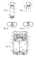
- FIG. 1 The distribution and packaging device or packaging according to the invention as illustrated in FIG. 1 comprises a rigid box of rectangular shape, this box is pierced with a channel terminated by an expulsion orifice 2 on one of its faces.
- This orifice is located on the median axis x-x at about a third of the length of the housing and centered in a recess on the face of it.
- Figure 2 shows the housing 1 which has in its lower part, a primary chamber 3.
- This primary chamber 3 is separated into two parts by a primary piston 4 sliding freely in this housing 1.
- a part of this primary chamber is intended to contain the product to be packaged while the other part is vented through a hole 6 in the bottom of the housing.
- This primary piston 4 is provided with a seal 5 to seal between the part of the primary chamber 3 in which the product to be packaged is located and the housing 1.
- a spring (not shown) is located between the bottom of the housing and the primary piston 4, this spring makes it possible to compress the product.
- the housing has in its upper part a secondary chamber 7 which communicates with the primary chamber 3 by a suction passage 8 provided with a non-return valve 9.
- the secondary chamber 7 has a shoulder 10 and communicates by a passage expulsion 11, also provided with a non-return valve 12, with the expulsion orifice 2.
- Each non-return valve 9 or 12 is for example composed of a hollow cylindrical body provided with orifices at each of its ends .
- the upstream part of this body is frustoconical while the other end of this body has a rim.
- a ball 13, 13 ′ whose diameter is greater than the diameter of the upstream orifice is placed in this body.
- the non-return valves 9, 12 are placed so as to allow the product to pass between the primary chamber 3 and the secondary chamber 7 and from the latter to the expulsion channel 2.
- a spring 15 is disposed in the secondary chamber 7 and bears on the one hand against the shoulder 10 of said chamber and on the other hand against a control member formed by a piston 16 secured to a push button 17 accessible from outside the housing 1.
- the piston 16 sliding without play in the secondary chamber compresses the dose of product contained in this secondary chamber 7 which displaces the ball 13 'against the action of its spring 14' and allows the expulsion of a quantity of product through the expulsion orifice 2.
- the non-return valve 9 prevents during this operation the product contained in the secondary chamber 7 to flow back into the primary chamber 3.
- the secondary chamber 7 is directly connected to the expulsion channel 2 without non-return valve.
- a slot 19 located parallel to the axis of the piston 16 is formed in the housing 1.
- the piston 16 is integral with a tongue 20 pierced with a slot 21.
- the slot 21 of the tongue 20 coincides with the expulsion channel 2 thus allowing the dose of product contained in the secondary chamber 7 to be expelled.
- the push button 17 returns to its rest position under the action of the spring 15, the tongue 20 closes the expulsion channel 2.
- the expulsion orifice being closed in the inactive position of the packaging there is no contact between the product and the outside air, thus ensuring total protection of the product against oxidation or contamination.
- FIG. 6 represents a third variant of the packaging and comprises a single chamber 22 separated into two parts by a free piston 23.
- One of the parts is filled with the product to be dispensed while the other is vented by a bore practiced in the bottom of the case.
- the housing comprises a tube 25 or guide posts located in the axis of the expulsion orifice, integral with the rear wall of the housing, the other end of this tube being located at a distance from the orifice. expulsion determined by the size of the obturation member described below.
- a ball 26 whose diameter is substantially greater than the diameter of the expulsion orifice is placed in this tube 25.
- a spring 27 in the tube 25 tends to apply the ball 26 against the expulsion orifice.
- the product being under pressure exits through the expulsion orifice until the pressure is released. pressure on the ball 26 which then again closes the expulsion orifice under the action of the spring 27.
- the user can thus determine the quantity of product desired.
- the ball 27 can be replaced by a cylindrical body 28 as illustrated in FIGS. 8 and 9.
- the head of this body 28 has a bevel cut 29.
- the cut 29 emerges from the housing under the action of the spring 27.
- the head of the body 28 sinks into the housing, the cutout 29, allowing the product to be expelled.
- FIG 10 shows a fourth variant of the packaging according to the first embodiment of the invention in which two different products are present in the housing and mix at the time of expulsion.
- the housing 1 comprises a primary chamber separated longitudinally into two half-chambers 30.30 'by a watertight partition 31, each of these half-chambers 30.30' comprises a free primary piston 32.32 ' fitted with a 33.33 'gasket.
- a spring 34.34 ' is introduced between the bottom of the housing and the primary piston 32.32' of each of the two half-chambers 30.30 'so that the products contained in each of the upper parts of said half-chambers 30.30 'are under pressure.
- the right-hand half-chamber 30 communicates by a suction channel, in which there is a non-return valve 35, with the secondary chamber 7 containing the control piston 16 secured to the push button 17 as in the first embodiment described above.
- La demicham- left bre 30 ' communicates by a suction channel provided with a non-return valve 35' with a second secondary chamber 36.
- This secondary chamber 36 comprises a piston 37.
- This piston 37 is integral with the control piston 16 sliding freely in the secondary chamber 7 by means of an axis 38 sealingly sliding in a passage 39 formed in the housing 1 between the secondary chambers 7 and 36.
- An expulsion channel 40 connects the second secondary chamber 36 to a second expulsion orifice 41 located near the first expulsion orifice 2 in the recess of the housing 1.
- the packaging or packaging and dispensing device according to the invention can be for single use or refillable, in this case the bottom of the case is removable and a refill can be introduced in the form of a cartridge having for example a bottom rigid whose shape corresponds to the case and a flexible bag containing the product.
- the bottom of the refill acts as the primary piston.
- the primary chamber is separated into two parts by a separation member, one of these parts being connected to the secondary chamber and the other to the open air.
- the separation member can be a free piston as described above or a membrane or a flexible or rigid part of a product refill.
- the packaging described has the following advantages.
- the product is never in contact with the outside air thus preventing any oxidation. Contact with fingers when using the product is limited to the dose that will be used, thus preventing contamination of the rest of the product.
- the packaging does not deform and enjoys aesthetic qualities far superior to those of deformable tubes.
- the use of the packaging is extremely simple and can be used with one hand which is not the case for tubes.
- the product can be used in its entirety which is not easy when dealing with plastic tubes.
- the external shape as well as the materials used for the manufacture of the packaging are adaptable to the storage constraints of transport and compatibility with the product. Finally, it is possible to simultaneously distribute doses of different products, in a proportion determined by the actuation of a single pusher.
- packaging we can save on secondary packaging.
- the packaging according to the invention can be distributed and sold without packaging, packaging or additional box, which is advantageous.
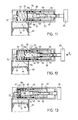
- the second embodiment of the device for packaging and distributing a pasty or liquid product illustrated partially in section in FIG. 11 comprises a rigid housing 50 having a chamber 51 intended to receive the product to be distributed connected by a channel 52 and a first non-return valve 53 at the bottom of a bore 54 receiving the product distribution mechanism.
- This product distribution mechanism consists of an outlet orifice 55 opening into the bore 54 of a main piston 56 sliding in the bore 54 against the action of a return spring 57.
- the main piston 56 has a chamber 58 opening on its front face and closed by a second non-return valve 59.
- This second non-return valve 59 is sandwiched between the front face of the main piston 56 and a washer 59a of which the hole is of a dimension corresponding to the passage of the valve 59.
- the washer 59a and the valve 59 are applied against the face of the piston 56 by the spring 57.
- This chamber 58 is connected by a channel 60 to an annular chamber 61 opening out on the periphery of the main piston. Seals are provided between the main piston 56 and the housing 50 near the front end of the piston and on each side of the annular chamber 61. These seals may have come from a molding piece with the piston 56.
- the main piston 56 also has a blind central bore 62, having a shoulder, opening into the chamber 58.
- a decompression piston 63 slides in this central bore freely under the action of a return spring 64.
- the main piston is integral with a pusher 65 for its actuation.
- a pusher 65 for its actuation.
- any organ or actuator, trigger, rack, etc. could be provided to move the main piston against the action of the spring 57 in the bore 54.
- the chamber 51 containing the product to be packaged and dispensed is closed towards the bottom of the case 50 by a movable bottom 66 provided with sealing lips rubbing against the case 50 and sliding freely in said chamber 51.
- the main piston 56 When the user releases the plunger 65, the main piston 56 returns to the rest position (fig. 11) under the action of the spring 57. In doing so, the non-return valve 59 closes preventing any call for air by the outlet 55 while the non-return valve 53 opens and the product from the chamber 51 is vacuum drawn through the channel 52 into the end of the bore 54. End of return stroke of the main piston 56, the outlet orifice 55 is again closed. The movable bottom 66 rises in the chamber 51 under the effect of the vacuum created, thus avoiding any contact of the product with the air.
- this mechanism is very simple, requires few parts and is easy to manufacture, the parts can either be easily machined, injected or molded.
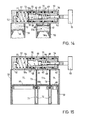
- the housing 50 has two chambers 51, 51a, intended to receive two different products, one pasty and the other liquid for example.
- the mechanism for dispensing and metering the product contained in the chamber 51 of the housing is identical to that described in relation to FIGS. 11 to 13.
- the mechanism for dispensing and metering the product contained in the chamber 51 a may include a check valve. non-return 67 located in the top of the chamber 51 a which has a hole 68 opening into the bore 54. In a variant, this non-return valve or valve 67 can be omitted.
- the main piston 56 comprises a second annular chamber 69, also delimited by seals, and the housing comprises a second outlet orifice 70.
- each of the chambers 51, 51 a has a movable bottom 66, 66a.
- the product contained in the chamber 51 is dispensed as previously described.
- the non-return valve 67 remains closed.
- the product contained in the chamber 51 has, pushed by the bottom 66a rigidly connected to the bottom 66 of the chamber 51, opens the non-return valve 67, enters the annular chamber 69 and is expelled through the outlet orifice 70.
- the annular chamber 69 is no longer in connection with the outlet orifice 70 and the hole 68, the expulsion of the second product is stopped.
- the displacement of the bottom 66 of the chamber 51 is used, taking place by vacuum to cause a corresponding displacement of the bottom 66a of the chamber 51 a. In this way, it is ensured that the two chambers 51 and 51 a are empty simultaneously.
- the device is similar to that described with reference to Figure 14, but the second chamber 51a is entirely surrounded by the chamber 51 which has a hollow cylindrical shape.
- the movable bottom 66 of the chamber 51 is also of annular shape.
- a piston skirt 71 or bottom of the housing 50 is provided which slides freely inside the external walls of the housing 50 and which is integral with the movable bottoms 66 and 66a.
- This piston skirt 71 has an annular groove 72 intended to give passage to the annular wall 73 of the second chamber 51 a during its upward movements. In this way, moving the movable bottom 66a is caused by the displacement of the piston skirt 71 entrained in the displacements of the movable bottom 66.
- the non-return valves consist of discs or washers of molded plastic material having a central tongue connected by a portion of its periphery to the disc.
- This disc has a hole of dimensions slightly smaller than those of the movable tongue by bending.
- the tongue is movable relative to the disc to either close the hole thereof, or on the contrary to free a passage through the disc.
- the disc has a weakening on one of its faces at the place where the tongue is connected to it.
- This check valve is very simple, inexpensive, easy to manufacture and has proven to be very reliable.
- the valve 53 has a disc with an outside diameter corresponding to the inside diameter of the blind bore 54 and is held against the bottom of the latter by the support of the spring 57.
- the valve 59 has an external diameter corresponding to the external diameter of the main piston 56 and is applied against the front end of the latter by a washer subjected to the action of the spring 57.
- valve 67 is held between a perforated partition in the upper part of the second chamber 51 a and an annular boss or washer situated between this pierced upper wall and the wall of the blind bore of the housing.
- the chambers 51 and / or 51 a could contain or be replaced by filled pockets containing the product to be dispensed. These pockets could be removably connected to the product outlet orifices in the bore 54 so that they can be discarded when they are empty and replaced by full pockets.
Abstract
Description
La présente invention a pour objet un dispositif pour le conditionnement et la distribution de produits pâteux ou liquides sous forme de gel ou d'émulsion comme par exemple des produits cosmétiques ou pharmaceutiques. Généralement pour conditionner de tels produits on utilise des tubes ou des pots. Les inconvénients liés à l'utilisation de tubes en plastique résident dans le fait qu'une fois ouverts, l'élasticité du plastique permet un rappel d'air a l'intérieur du tube ce qui, après chaque expulsion d'une dose de produit, présente des problèmes d'oxydation ou de contamination du contenu. Les tubes en aluminium ne présentent pas cet inconvénient mais leur déformabilité les rend inesthétiques et peu pratiques après quelques utilisations.The present invention relates to a device for the packaging and distribution of pasty or liquid products in the form of a gel or emulsion such as, for example, cosmetic or pharmaceutical products. Generally to package such products, tubes or jars are used. The drawbacks linked to the use of plastic tubes reside in the fact that once opened, the elasticity of the plastic allows air to be drawn back inside the tube which, after each expulsion of a dose of product , presents problems of oxidation or contamination of the contents. Aluminum tubes do not have this drawback, but their deformability makes them unsightly and impractical after a few uses.
Les pots de crème largement utilisés présentent l'inconvénient d' une grande surface de contact entre le contenu et l'environnement d'où des risques importants d'oxydation et de contamination.Widely used cream jars have the disadvantage of a large contact surface between the content and the environment, resulting in significant risks of oxidation and contamination.
La présente invention a pour objet un dispositif pour le conditionnement et la distribution des produits pâteux ou liquides qui remédie aux inconvénients précités et se distingue par les caractéristiques énumérées à la revendication 1.The present invention relates to a device for the packaging and distribution of pasty or liquid products which overcomes the aforementioned drawbacks and is distinguished by the characteristics listed in
Le dessin annexé illustre schématiquement et à titre d'exemple un dispositif ou un emballage distributeur pour produits pâteux ou liquides selon l'invention.
- La figure 1 est une vue en perspective du dispositif suivant une première forme d'exécution de l'invention.
- La figure 1 a en est une vue de face.
- La figure 1 b en est une vue de profil.
- La figure 2 est une vue en coupe suivant la ligne II-II de la figure 1 b d'une première variante, le bouton poussoir étant en position enfoncée.
- La figure 3 est une vue en coupe semblable de la première variante, le bouton poussoir étant en position relâchée.
- La figure 4 est une vue en coupe partielle suivant la ligne II-II de la figure 1 b d'une deuxième variante, le bouton poussoir étant en position enfoncée.
- La figure 5 est une vue en coupe semblable de la deuxième variante, le bouton poussoir étant en position relâchée.
- La figure 6 est une vue en coupe suivant la ligne x-x de la figure 1 a d'une troisième variante, l'orifice d'expulsion étant obturé.
- La figure 7 est une vue en coupe partielle de la troisième variante, l'orifice d'expulsion étant ouvert.
- La figure 8 est une vue en coupe selon la ligne III-III de la figure 7 représentant une variante de 1 organe d'obturation dans la troisième variante du dispositif.
- La figure 9 est une vue en coupe de la variante illustrée à la figure 8, l'organe d'obturation étant en position ouverte.
- La figure 10 est une vue en coupe selon la ligne II-II de la figure 1 b d'une quatrième variante de la première forme d'exécution du dispositif.
- La figure 11 est une vue en coupe partielle d'une seconde forme d'exécution du dispositif selon l'invention.
- Les figures 12 et 13 sont des coupes similaires à celles de la figure 11, le piston principal du dispositif étant dans d'autres positions de fonctionnement.
- La figure 14 est une coupe partielle d'une troisième forme d'exécution du dispositif selon l'invention.
- La figure 15 est une coupe partielle d'une quatrième forme d'exécution du dispositif selon l'invention.
- Figure 1 is a perspective view of the device according to a first embodiment of the invention.
- Figure 1a is a front view.
- Figure 1b is a side view.
- Figure 2 is a sectional view along line II-II of Figure 1b of a first variant, the push button being in the depressed position.
- Figure 3 is a similar sectional view of the first variant, the push button being in the released position.
- Figure 4 is a partial sectional view along line II-II of Figure 1b of a second variant, the push button being in the depressed position.
- Figure 5 is a similar sectional view of the second variant, the push button being in the released position.
- Figure 6 is a sectional view along line xx of Figure 1a of a third variant, the expulsion orifice being closed.
- Figure 7 is a partial sectional view of the third variant, the expulsion orifice being open.
- Figure 8 is a sectional view along line III-III of Figure 7 showing a variant of 1 closure member in the third variant of the device.
- Figure 9 is a sectional view of the variant illustrated in Figure 8, the shutter member being in the open position.
- Figure 10 is a sectional view along line II-II of Figure 1b of a fourth variant of the first embodiment of the device.
- Figure 11 is a partial sectional view of a second embodiment of the device according to the invention.
- Figures 12 and 13 are sections similar to those of Figure 11, the main piston of the device being in other operating positions.
- Figure 14 is a partial section of a third embodiment of the device according to the invention.
- Figure 15 is a partial section of a fourth embodiment of the device according to the invention.
Le dispositif de distribution et de conditionnement ou emballage selon l'invention tel qu'illustré à la figure 1 comporte un boîtier rigide de forme rectangulaire, ce boîtier est percé d'un canal terminé par un orifice d'expulsion 2 sur l'une de ses faces. Cet orifice est situé sur l'axe médian x-x à environ un tiers de la longueur du boîtier et centré dans une creusure de la face de celui-ci. La figure 2 montre le boîtier 1 qui comporte dans sa partie inférieure, une chambre primaire 3. Cette chambre primaire 3 est séparée en deux parties par un piston primaire 4 coulissant librement dans ce boîtier 1. Une partie de cette chambre primaire est destinée à contenir le produit à conditionner tandis que l'autre partie est mise à l'air libre par un perçage 6 du fond du boîtier. Ce piston primaire 4 est muni d'un joint 5 pour assurer l'étanchéité entre la partie de la chambre primaire 3 dans laquelle se trouve le produit à conditionner et le boîtier 1. Dans une variante un ressort (non illustré) se trouve entre le fond du boîtier et le piston primaire 4, ce ressort permet de comprimer le produit.The distribution and packaging device or packaging according to the invention as illustrated in FIG. 1 comprises a rigid box of rectangular shape, this box is pierced with a channel terminated by an
Le boîtier comporte dans sa partie supérieure une chambre secondaire 7 qui communique avec la chambre primaire 3 par un passage d'aspiration 8 muni d'un clapet de non retour 9. La chambre secondaire 7 comporte un épaulement 10 et communique par un passage d'expulsion 11, également muni d'un clapet de non retour 12, avec l'orifice d'expulsion 2. Chaque clapet de non retour 9 ou 12 est par exemple composé d'un corps cylindrique creux muni d'orifices à chacune de ses extrémités. La partie amont de ce corps est tronconique tandis que l'autre extrémité de ce corps présente un rebord. Une bille 13,13' dont le diamètre est supérieur au diamètre de l'orifice amont est placée dans ce corps. Un ressort 14,14' tend à appliquer la bille 13,13' contre la face interne de la partie tronconique du corps. Les clapets de non retour 9,12 sont placés de manière à permettre le passage du produit entre la chambre primaire 3 et la chambre secondaire 7 et de celle-ci vers le canal d'expulsion 2.The housing has in its upper part a
Un ressort 15 est disposé dans la chambre secondaire 7 et vient prendre appui d'une part contre l'épaulement 10 de ladite chambre et d'autre part contre un organe de commande formé d'un piston 16 solidaire d'un bouton poussoir 17 accessible depuis l'extérieur du boîtier 1. Lorsque l'on actionne le bouton poussoir 17 dans le sens de la flèche A, le piston 16 coulissant sans jeu dans la chambre secondaire comprime la dose de produit contenue dans cette chambre secondaire 7 ce qui déplace la bille 13' contre l'action de son ressort 14' et permet l'expulsion d'une quantité de produit par l'orifice d'expulsion 2. Le clapet de non retour 9 empêche pendant cette opération le produit contenu dans la chambre secondaire 7 de refluer dans la chambre primaire 3. Lorsque le bouton poussoir 17 revient dans sa position initiale sous l'action du ressort 15, une dépression est créée dans la chambre secondaire 7 ce qui a pour effet d'obturer le clapet de non retour 12 et de provoquer un appel de produit de la chambre primaire vers la chambre secondaire à travers le clapet de non retour 9. Le piston primaire se déplace dans le sens de la flèche B sous l'action de la pression atmosphérique et éventuellement d'un ressort d'appoint (non illustré) ajustant le volume de la partie de la chambre primaire contenant le produit au volume restant de celui-ci.A
Il est à noter que seule la très faible quantité de produit restant dans le clapet de non retour 12 est en contact avec l'air extérieur et donc soumise à une éventuelle oxydation ou contamination.It should be noted that only the very small amount of product remaining in the
Dans la deuxième variante illustrée aux figures 4 et 5 la chambre secondaire 7 est reliée directement au canal d'expulsion 2 sans clapet de non retour. Une fente 19 située parallèlement à l'axe du piston 16 est ménagée dans le boîtier 1. Le piston 16 est solidaire d'une languette 20 percée d'une fente 21. Lorsque le bouton poussoir 17 est en position enfoncée comme illustré à la figure 4, la fente 21 de la languette 20 vient coïncider avec le canal d'expulsion 2 permettant ainsi à la dose de produit contenue dans la chambre secondaire 7 d'être expulsée. Lorsque le bouton poussoir 17 revient dans sa position de repos sous l'action du ressort 15, la languette 20 vient obturer le canal d'expulsion 2. Dans cette forme d'exécution, l'orifice d'expulsion étant obturé en position inactive de l'emballage il n'y a pas de contact entre le produit et l'air extérieur, assurant de ce fait une protection totale du produit contre l'oxydation ou la contamination.In the second variant illustrated in Figures 4 and 5 the
La figure 6 représente une troisième variante de l'emballage et comporte une chambre unique 22 séparée en deux parties par un piston libre 23. Une des parties est remplie du produit à distribuer tandis que l'autre est mise à l'air par un perçage pratiqué dans le fond du boîtier. Un ressort 24 prenant appui d'une part contre le fond du boîtier et d'autre part contre le piston libre 23 permet de mettre le produit sous pression. Le boîtier comporte un tube 25 ou des colonnettes de guidage situé dans l'axe de l'orifice d'expulsion, solidaire de la paroi arrière du boîtier, l'autre extrémité de ce tube étant située à une distance de l'orifice d'expulsion déterminée par la taille de l'organe d'obturation décrit ci-dessous. Une bille 26 dont le diamètre est sensiblement supérieur au diamètre de l'orifice d'expulsion est placée dans ce tube 25. Un ressort 27 dans le tube 25 tend à appliquer la bille 26 contre l'orifice d'expulsion. Lorsque l'on exerce une pression avec le doigt sur la partie de la bille 26 qui émerge de l'orifice d'expulsion, le produit étant sous pression sort par l'orifice d'expulsion jusqu'à ce que l'on relâche la pression sur la bille 26 qui vient alors à nouveau obturer l'orifice d'expulsion sous l'action du ressort 27.FIG. 6 represents a third variant of the packaging and comprises a
L'utilisateur peut ainsi déterminer la quantité de produit désirée. La bille 27 peut être remplacée par un corps 28 cylindrique tel qu'illustré aux figures 8 et 9. La tête de ce corps 28 comporte une découpe en biseau 29. La découpe 29 émerge du boîtier sous l'action du ressort 27. Lorsque l'on exerce une pression sur ce corps (fig 9), la tête du corps 28 s'enfonce dans le boîtier, la découpe 29, permettant au produit d'être expulsé. Cette solution a l'avantage que la sortie du produit ne s'effectue que par la découpe 29, c'est-à-dire suivant une direction privilégiée rendant l'utilisation de l'emballage plus aisée.The user can thus determine the quantity of product desired. The
La figure 10 montre une quatrième variante de l'emballage selon la première forme d'exécution de l'invention dans laquelle deux produits différents sont présents dans le boîtier et se mélangent au moment de l'expulsion. Dans cette forme d'exécution, le boîtier 1 comporte une chambre primaire séparée longitudinalement en deux demi-chambres 30,30' par une cloison étanche 31, chacune de ces demi-chambres 30,30' comporte un piston primaire libre 32,32' muni d'un joint d'étanchéité 33,33'. Un ressort 34,34' est introduit entre le fond du boîtier et le piston primaire 32,32' de chacune des deux demi-chambres 30,30' de sorte que les produits contenus dans chacune des parties supérieures desdites demi-chambres 30,30' soient sous pression. La demi-chambre de droite 30 communique par un canal d'aspiration, dans lequel se situe un clapet de non retour 35, avec la chambre secondaire 7 contenant le piston de commande 16 solidaire du bouton poussoir 17 comme dans la première forme d'exécution décrite ci dessus. La demicham- bre de gauche 30' communique par un canal d'aspiration muni d'un clapet de non retour 35' avec une deuxième chambre secondaire 36. Cette chambre secondaire 36 comporte un piston 37. Ce piston 37 est solidaire du piston de commande 16 coulissant librement dans la chambre secondaire 7 par l'intermédiaire d'un axe 38 coulissant de façon étanche dans un passage 39 ménagé dans le boîtier 1 entre les chambres secondaires 7 et 36. Un canal d'expulsion 40 relie la deuxième chambre secondaire 36 a un second orifice d'expulsion 41 situé à proximité du premier orifice d'expulsion 2 dans la creusure du boîtier 1. Lorsque l'on actionne le bouton poussoir 17 dans le sens de la flèche A, le piston 16 entraînant le piston 37, comprime les doses de produits contenues dans les chambres secondaires 7,36 et les doses de produits sont expulsées respectivement par les orifices 2 et 41. Les clapets de non retour 35,35' empêchent les produits de refluer vers les demi-chambres primaires 30,30'. Lorsque les pistons 16,37 reviennent en position de service sous l'action des ressorts, une dépression est crée dans les chambres secondaires 7,36 ce qui provoque un appel de produit des demichambres 30,30' vers les chambres secondaires 7,36 à travers les clapets de non-retour 35,35'. Les pistons primaires 32,32' se déplacent dans le sens des flèches B B' sous l'action des ressorts 34,34'. Cette forme d'exécution de l'emballage, permet d'expulser une dose composée de deux produits différents qui ne se mélangent qu'au moment de l'utilisation. Dans cette forme d'exécution, le piston 16 peut coopérer avec un organe d'obturation des deux orifices d'expulsion 2,41 comme celui décrit dans la deuxième forme d'exécution aux figures 4 et 5.Figure 10 shows a fourth variant of the packaging according to the first embodiment of the invention in which two different products are present in the housing and mix at the time of expulsion. In this embodiment, the
En variant le diamètre des chambres secondaires 7,36 l'un par rapport à l'autre on modifie la proportion des produits expulsés simultanément.By varying the diameter of the secondary chambers 7.36 relative to one another, the proportion of the products expelled simultaneously is modified.
L'emballage ou dispositif de conditionnement et de distribution selon l'invention peut être à usage unique ou rechargeable, dans ce cas le fond du boîtier est amovible et l'on peut introduire une recharge sous forme d'une cartouche ayant par exemple un fond rigide dont la forme correspond au boîtier et un sac souple contenant le produit. Le fond de la recharge fait office de piston primaire.The packaging or packaging and dispensing device according to the invention can be for single use or refillable, in this case the bottom of the case is removable and a refill can be introduced in the form of a cartridge having for example a bottom rigid whose shape corresponds to the case and a flexible bag containing the product. The bottom of the refill acts as the primary piston.
D'une façon générale la chambre primaire est séparée en deux parties par un organe de séparation, l'une de ces parties étant reliée à la chambre secondaire et l'autre à l'air libre. L'organe de séparation peut être un piston libre comme décrit plus haut ou une membrane ou une partie souple ou rigide d'une recharge de produit.Generally, the primary chamber is separated into two parts by a separation member, one of these parts being connected to the secondary chamber and the other to the open air. The separation member can be a free piston as described above or a membrane or a flexible or rigid part of a product refill.
L'emballage décrit présente les avantages suivants. Le produit n'est jamais en contact avec l'air extérieur empêchant ainsi toute oxydation. Le contact avec les doigts lorsque l'on se sert du produit est limité à la dose que l'on va utiliser empêchant ainsi toute contamination du reste du produit. L'emballage ne se déforme pas et jouit de qualités esthétiques largement supérieures à celles des tubes déformables. L'utilisation de l'emballage est extrêmement simple et peut être utilisé d'une seule main ce qui n'est pas le cas des tubes. Le produit peut être utilisé dans sa totalité ce qui n'est pas aisé lorsque l'on a à faire à des tubes en plastique. La forme extérieure ainsi que les matériaux utilisés pour la fabrication de l'emballage sont adaptables aux contraintes de stockage de transport et de compatibilité avec le produit. Enfin, il est possible de distribuer simultanément des doses de produits différents, dans une proportion déterminée par l'actionnement d'un seul poussoir.The packaging described has the following advantages. The product is never in contact with the outside air thus preventing any oxidation. Contact with fingers when using the product is limited to the dose that will be used, thus preventing contamination of the rest of the product. The packaging does not deform and enjoys aesthetic qualities far superior to those of deformable tubes. The use of the packaging is extremely simple and can be used with one hand which is not the case for tubes. The product can be used in its entirety which is not easy when dealing with plastic tubes. The external shape as well as the materials used for the manufacture of the packaging are adaptable to the storage constraints of transport and compatibility with the product. Finally, it is possible to simultaneously distribute doses of different products, in a proportion determined by the actuation of a single pusher.
Il faut encore noter qu'avec cet emballage on peut faire l'économie d'un emballage secondaire. En effet, l'emballage selon l'invention peut être distribué et vendu sans conditionnement, emballage ou boite supplémentaire, ce qui est avantageux.It should also be noted that with this packaging we can save on secondary packaging. In fact, the packaging according to the invention can be distributed and sold without packaging, packaging or additional box, which is advantageous.
La seconde forme d'exécution du dispositif de conditionnement et de distribution d'un produit pâteux ou liquide illustré partiellement en coupe à la figure 11 comporte un boîtier rigide 50 présentant une chambre 51 destinée à recevoir le produit à distribuer reliée par un canal 52 et un premier clapet de non-retour 53 au fond d'un alésage 54 recevant le mécanisme de distribution du produit.The second embodiment of the device for packaging and distributing a pasty or liquid product illustrated partially in section in FIG. 11 comprises a
Ce mécanisme de distribution du produit est constitué par un orifice de sortie 55 débouchant dans l'alésage 54 d'un piston principal 56 coulissant dans l'alésage 54 contre l'action d'un ressort de rappel 57.This product distribution mechanism consists of an
Le piston principal 56 comporte une chambre 58 débouchant sur sa face frontale et obturée par un second clapet de non-retour 59. Ce second clapet de non-retour 59 est pincé en sandwich entre la face frontale du piston principal 56 et une rondelle 59a dont le trou est d'une dimension correspondant au passage de la soupape 59. La rondelle 59a et la soupape 59 sont appliquées contre la face du piston 56 par le ressort 57. Cette chambre 58 est reliée par un canal 60 à une chambre annulaire 61 débouchant sur la périphérie du piston principal. Des joints sont prévus entre le piston principal 56 et le boîtier 50 à proximité de l'extrémité frontale du piston et de chaque côté de la chambre annulaire 61. Ces joints peuvent être venus d'une pièce de moulage avec le piston 56.The
Le piston principal 56 comporte encore un alésage central borgne 62, présentant un épaulement, débouchant dans la chambre 58. Un piston 63 de décompression coulisse dans cet alésage central librement sous l'action d'un ressort de rappel 64.The
Dans cette forme d'exécution le piston principal est solidaire d'un poussoir 65 pour son actionnement. Il est évident que n'importe quel organe ou dispositif d'actionnement, à gâchette, à crémaillère, etc. pourrait être prévu pour déplacer le piston principal contre l'action du ressort 57 dans l'alésage 54.In this embodiment, the main piston is integral with a
La chambre 51 contenant le produit à conditionner et à distribuer est obturée vers le fond du boîtier 50 par un fond mobile 66 muni de lèvres d'étanchéité frottant contre le boîtier 50 et coulissant librement dans ladite chambre 51.The
Le fonctionnement du dispositif doseur ou de distribution décrit est le suivant :
- A l'état de repos, le dispositif est dans la position illustrée à la figure 11.
Le canal 52,la chambre 58,le canal 60 et la chambre annulaire 61 sont plein de produit à distribuer. L'orifice de sortie 55 est obturé parle piston principal 56.
- In the rest state, the device is in the position illustrated in FIG. 11. The
channel 52, thechamber 58, thechannel 60 and theannular chamber 61 are full of product to be dispensed. Theoutlet orifice 55 is closed by themain piston 56.
A partir de cet état l'utilisateur pousse le poussoir 65 suivant la flèche F déplaçant le piston principal 56 à l'intérieur de l'alésage 54 contre l'action du ressort 57 ce qui provoque :
- - dans un premier temps (fig. 12) la fermeture du clapet de non-retour 53 et l'ouverture du clapet de non-retour 59 autorisant l'introduction du produit contenu dans le fond de l'alésage 54 dans la chambre 58 du
piston principal 56 provoquant le déplacement du piston de décompression 63 contre l'action de son ressort de rappel 64. Ainsi, bien que l'orifice de sortie 55 soit fermé, le produit à distribuer n'est pas mis sous pression par le déplacement dupiston principal 56; - - dans un second temps (fig. 13), dès que la chambre annulaire 60 du
piston principal 56 est en communication avec l'orifice de sortie, tout déplacement subséquent dupiston principal 56 provoque l'expulsion d'une dose de produit, dose dont le volume est défini par la course et le diamètre de ce piston principal. La fin de la distribution du produit intervient soit quand le piston principal arrive en fin de course, soit quand la chambre annulaire 61 de ce piston n'est plus en communication avec l'orifice de sortie. Entre-temps, le piston secondaire est revenu en position de repos sous l'action de son ressort de rappel.
- - firstly (fig. 12) closing the
non-return valve 53 and opening thenon-return valve 59 authorizing the introduction of the product contained in the bottom of thebore 54 into thechamber 58 of themain piston 56 causing the displacement of thedecompression piston 63 against the action of itsreturn spring 64. Thus, although theoutlet orifice 55 is closed, the product to be dispensed is not pressurized by the displacement of themain piston 56; - - in a second step (fig. 13), as soon as the
annular chamber 60 of themain piston 56 is in communication with the outlet orifice, any subsequent movement of themain piston 56 causes the expulsion of a dose of product, dose whose volume is defined by the stroke and the diameter of this main piston. The end of the product distribution occurs either when the main piston reaches the end of the stroke, or when theannular chamber 61 of this piston is no longer in communication with the outlet orifice. Meanwhile, the secondary piston has returned to the rest position under the action of its return spring.
Lorsque l'utilisateur relâche le poussoir 65, le piston principal 56 retourne en position de repos (fig. 11) sous l'action du ressort 57. Ce faisant, le clapet de non-retour 59 se ferme interdisant tout appel d'air par l'orifice de sortie 55 tandis que le clapet de non-retour 53 s ouvre et que du produit de la chambre 51 est aspiré par vacuum au travers du canal 52 dans l'extrémité de l'alésage 54. En fin de course de retour du piston principal 56, l'orifice de sortie 55 est à nouveau obturé. Le fond mobile 66 remonte dans la chambre 51 sous l'effet du vacuum créé, évitant ainsi tout contact du produit avec l'air.When the user releases the
De plus, ce mécanisme est très simple, nécessite peu de pièces et est facile à fabriquer, les pièces pouvant soit être facilement usinées, injectées ou moulées.In addition, this mechanism is very simple, requires few parts and is easy to manufacture, the parts can either be easily machined, injected or molded.
Dans la troisième forme d'exécution du dispositif illustré à la figure 14, le boîtier 50 comporte deux chambres 51, 51 a, destinées à recevoir deux produits différents, l'un pâteux et l'autre liquide par exemple. Le mécanisme de distribution et de dosage du produit contenu dans la chambre 51 du boîtier est identique à celui décrit en relation avec les figures 11 à 13. Le mécanisme de distribution et de dosage du produit contenu dans la chambre 51 a peut comporter un clapet de non-retour 67 situé dans le haut de la chambre 51 a qui comporte un trou 68 débouchant dans l'alésage 54. Dans une variante, cette soupape ou clapet de non-retour 67 peut être supprimée. Le piston principal 56 comporte une seconde chambre annulaire 69, également délimitée par des joints, et le boîtier comporte un second orifice de sortie 70. Enfin, chacune des chambres 51, 51 a, comporte un fond mobile 66, 66a.In the third embodiment of the device illustrated in Figure 14, the
Lorsque 1 usager appuie sur le poussoir 65, la distribution du produit contenu dans la chambre 51 s'effectue comme précédemment décrit. Pendant cette course aller du piston principal 56, le clapet de non-retour 67 reste fermé. Par contre, lors de la course de retour du piston principal 56, pendant que la chambre annulaire 69 est en communication avec le trou 68, le produit contenu dans la chambre 51 a, poussé par le fond 66a relié rigidement au fond 66 de la chambre 51, ouvre le clapet de non-retour 67, pénètre dans la chambre annulaire 69 et est expulsé par l'orifice de sortie 70. Dès que la chambre annulaire 69 n'est plus en liaison avec l'orifice de sortie 70 et le trou 68, l'expulsion du second produit est stoppée. Ainsi, pour l'expulsion du produit contenu dans la chambre 51 a, on utilise le déplacement du fond 66 de la chambre 51, s'effectuant par vacuum pour provoquer un déplacement correspondant du fond 66a de la chambre 51 a. De cette façon, on s'assure que les deux chambres 51 et 51 a sont vides simultanément.When 1 user presses the
Dans la quatrième forme d'exécution illustrée à la figure 15, le dispositif est similaire à celui décrit en référence à la figure 14, mais la seconde chambre 51 a est entièrement entourée par la chambre 51 qui présente une forme cylindrique creuse. Le fond mobile 66 de la chambre 51 est également de forme annulaire. Une jupe-piston 71 ou fond du boîtier 50 est prévu qui coulisse librement à l'intérieur des parois externes du boîtier 50 et qui est solidaire des fonds mobiles 66 et 66a. Cette jupe-piston 71 comporte une rainure annulaire 72 destinée à donner passage à la paroi annulaire 73 de la seconde chambre 51 a lors de ses déplacements vers le haut. De cette façon, le déplacement du fond mobile 66a est provoqué par le déplacement de la jupe-piston 71 entraînée dans les déplacements du fond mobile 66.In the fourth embodiment illustrated in Figure 15, the device is similar to that described with reference to Figure 14, but the
Dans cette dernière forme d'exécution, le clapet de non-retour 67 est supprimé, l'étanchéité de la seconde chambre 51 a étant assurée par le jeu du piston principal et des orifices 68 et 70.In this latter embodiment, the
Dans les trois dernières formes d'exécution décrites, les clapets de non-retour sont constitués par des disques ou rondelles en matière plastique moulée présentant une languette centrale reliée par une portion de son pourtour au disque. Ce disque présente un trou de dimensions légèrement inférieures à celles de la languette mobile par flexion. La languette est déplaçable par rapport au disque pour soit obturer le trou de celui-ci, soit au contraire pour libérer un passage au travers du disque. Pour faciliter la déformation élastique de la languette de façon préférentielle dans un sens, le disque présente un affaiblissement sur l'une de ses faces à l'endroit où la languette lui est raccordée.In the last three embodiments described, the non-return valves consist of discs or washers of molded plastic material having a central tongue connected by a portion of its periphery to the disc. This disc has a hole of dimensions slightly smaller than those of the movable tongue by bending. The tongue is movable relative to the disc to either close the hole thereof, or on the contrary to free a passage through the disc. To facilitate the elastic deformation of the tongue preferably in one direction, the disc has a weakening on one of its faces at the place where the tongue is connected to it.
Ce clapet de non-retour est très simple, bon marché, facile à fabriquer et s'est avéré très fiable.This check valve is very simple, inexpensive, easy to manufacture and has proven to be very reliable.
Le clapet 53 présente un disque d'un diamètre extérieur correspondant au diamètre intérieur de l'alésage borgne 54 et est maintenu contre le fond de celui-ci par l'appui du ressort 57.The
Le clapet 59 présente un diamètre externe correspondant au diamètre extérieur du piston principal 56 et est appliqué contre l'extrémité frontale de celui-ci par une rondelle soumise à l'action du ressort 57.The
Enfin, le clapet 67 est maintenu entre une cloison perforée dans la partie supérieure de la seconde chambre 51 a et un bossage annulaire ou rondelle situé entre cette paroi supérieure percée et la paroi de l'alésage borgne du boîtier.Finally, the
Dans des variantes du dispositif, les chambres 51 et/ou 51 a pourraient contenir ou être remplacées par des poches remplies contenant le produit à distribuer. Ces poches pourraient être reliées de façon amovible aux orifices de sortie du produit dans l'alésage 54 de manière à pouvoir être jetées lorsqu'elles sont vides et remplacées par des poches pleines.In variants of the device, the
Ces trois dernières formes d'exécution du dispositif selon l'invention résolvent les mêmes problèmes et présentent les mêmes avantages que ceux énumérés en se référant à la première forme d'exécution.These last three embodiments of the device according to the invention solve the same problems and have the same advantages as those listed with reference to the first embodiment.
Claims (25)
Applications Claiming Priority (4)
| Application Number | Priority Date | Filing Date | Title |
|---|---|---|---|
| CH225991A CH686037A5 (en) | 1991-07-29 | 1991-07-29 | Container/dispenser for produce in liquid or cream form |
| CH2259/91 | 1991-07-29 | ||
| CH1894/92 | 1992-06-16 | ||
| CH189492A CH686505A5 (en) | 1992-06-16 | 1992-06-16 | Container/dispenser for produce in liquid or cream form |
Publications (3)
| Publication Number | Publication Date |
|---|---|
| EP0526811A2 true EP0526811A2 (en) | 1993-02-10 |
| EP0526811A3 EP0526811A3 (en) | 1993-09-22 |
| EP0526811B1 EP0526811B1 (en) | 1997-03-12 |
Family
ID=25688943
Family Applications (1)
| Application Number | Title | Priority Date | Filing Date |
|---|---|---|---|
| EP92112651A Expired - Lifetime EP0526811B1 (en) | 1991-07-29 | 1992-07-24 | Storage and distribution device for liquid or pasty products |
Country Status (5)
| Country | Link |
|---|---|
| US (1) | US5361944A (en) |
| EP (1) | EP0526811B1 (en) |
| JP (1) | JPH05192558A (en) |
| AT (1) | ATE149952T1 (en) |
| DE (1) | DE69218066D1 (en) |
Cited By (2)
| Publication number | Priority date | Publication date | Assignee | Title |
|---|---|---|---|---|
| FR2718109A1 (en) * | 1994-03-30 | 1995-10-06 | Reboul Smt | Refillable packaging and its cartridge. |
| FR2718417A1 (en) * | 1994-04-12 | 1995-10-13 | Valois Sa | Container for pasty products with non-round follower piston. |
Families Citing this family (15)
| Publication number | Priority date | Publication date | Assignee | Title |
|---|---|---|---|---|
| US5439141A (en) * | 1994-07-21 | 1995-08-08 | Scott Paper Company | Dual liquid spraying system |
| US5711457A (en) * | 1996-10-10 | 1998-01-27 | Calmar Inc. | Trigger sprayer for dispensing liquids combined from separate compartments |
| NZ337222A (en) | 1997-01-17 | 2000-10-27 | Niagara Pump Corp | Linear peristaltic pump |
| DE19938798A1 (en) | 1999-08-16 | 2001-03-01 | Pfeiffer Erich Gmbh & Co Kg | Dispenser for liquids or for viscous or sprayable products |
| US6382472B1 (en) * | 2001-03-07 | 2002-05-07 | Doron Shoval | Viscous fluid dispenser |
| WO2005032729A1 (en) * | 2003-10-03 | 2005-04-14 | Kao Corporation | Discharge device |
| EP1709945A1 (en) * | 2005-04-08 | 2006-10-11 | Helbling Technik Bern AG | Dispensing device for delivering fluid comprising a dosing chamber and a slide valve assembly |
| US7726520B2 (en) * | 2005-12-22 | 2010-06-01 | Innopak Inc. | Metered dispenser with feed-containing piston drive mechanism |
| US20090057345A1 (en) * | 2007-08-31 | 2009-03-05 | Dukes Stephen A | Fluid dispenser |
| US8262592B1 (en) | 2007-12-27 | 2012-09-11 | Brooks Ray G | Fluid dispenser |
| US8133309B2 (en) | 2008-07-16 | 2012-03-13 | General Electric Company | Turbomachine filter system having a drain with one-way valve |
| RU2491219C1 (en) * | 2010-02-24 | 2013-08-27 | Колгейт-Палмолив Компани | Cover for distributor with selectable tanks |
| FR2958131B1 (en) * | 2010-03-30 | 2012-10-12 | Toly Korea Inc | COSMETIC HOUSING WHICH CAN OPEN TO DOUBLE TUBE PROTECTION STRUCTURE |
| USD669792S1 (en) * | 2011-03-10 | 2012-10-30 | R.J. Reynolds Tobacco Company | Spray dispensing container |
| FR3053579B1 (en) * | 2016-07-06 | 2018-08-17 | Galderma Research & Development | DEVICE FOR PACKAGING AND DISPENSING A PRODUCT, IN PARTICULAR A COSMETIC PRODUCT |
Citations (5)
| Publication number | Priority date | Publication date | Assignee | Title |
|---|---|---|---|---|
| US3760986A (en) * | 1970-08-19 | 1973-09-25 | Schuyler Dev Corp | Dispensing bottles with pump means for simultaneous dispensing |
| EP0282595A1 (en) * | 1986-07-31 | 1988-09-21 | Pentel Kabushiki Kaisha | Fluid discharge mechanism |
| FR2634825A1 (en) * | 1988-07-26 | 1990-02-02 | Andre Debard | Precompression pump for spraying a liquid |
| FR2641337A2 (en) * | 1988-07-26 | 1990-07-06 | Andre Debard | Pump with precompression for spraying a liquid |
| FR2647757A1 (en) * | 1989-06-05 | 1990-12-07 | Postollec Madeleine | Dispenser of predetermined doses of a liquid or pasty product, in particular of a food or cosmetic product |
Family Cites Families (14)
| Publication number | Priority date | Publication date | Assignee | Title |
|---|---|---|---|---|
| US1164754A (en) * | 1915-03-08 | 1915-12-21 | William H Rose | Soap-dispenser. |
| US2233716A (en) * | 1938-06-06 | 1941-03-04 | U S Sanitary Specialties Corp | Lather dispensing valve |
| US2283529A (en) * | 1938-12-27 | 1942-05-19 | Arthur L Bobrick | Dispenser for liquid soap and the like |
| US2622539A (en) * | 1947-03-08 | 1952-12-23 | Orlie E Martin | Liquid soap dispenser having a valve and plunger mechanism |
| US2529365A (en) * | 1947-05-06 | 1950-11-07 | Barksdale George Roy | Liquid soap dispenser |
| US2703191A (en) * | 1952-07-10 | 1955-03-01 | K P Mfg Co | Multistage lubricating gun |
| US2824673A (en) * | 1956-08-06 | 1958-02-25 | Patrick G Hanlon | Soap dispenser |
| DE3121075A1 (en) * | 1981-05-27 | 1982-12-23 | Wischerath & Schreiner KG, 8744 Mellrichstadt | DONOR |
| US4485943A (en) * | 1982-03-08 | 1984-12-04 | Joachim Czech | Dispenser for liquids or pasty products |
| US4502617A (en) * | 1983-01-31 | 1985-03-05 | Stoelting, Inc. | Flavor decanter and pump |
| US4687663B1 (en) * | 1983-03-01 | 1997-10-07 | Chesebrough Ponds Usa Co | Dental preparation article and method for storage and delivery thereof |
| FR2602967B1 (en) * | 1986-08-20 | 1990-06-08 | Colgate Palmolive Co | DISPENSING DEVICE FOR WASHING PRODUCTS FOR A DISHWASHER |
| US4949874A (en) * | 1987-12-04 | 1990-08-21 | Henkel Kommanditgesellschaft Auf Aktien | Device for dispensing at least two flowable substances |
| US4872596A (en) * | 1988-03-15 | 1989-10-10 | Calmar Inc. | Viscous product dispenser |
-
1992
- 1992-07-24 DE DE69218066T patent/DE69218066D1/en not_active Expired - Lifetime
- 1992-07-24 EP EP92112651A patent/EP0526811B1/en not_active Expired - Lifetime
- 1992-07-24 AT AT92112651T patent/ATE149952T1/en not_active IP Right Cessation
- 1992-07-28 US US07/920,684 patent/US5361944A/en not_active Expired - Fee Related
- 1992-07-29 JP JP4220927A patent/JPH05192558A/en active Pending
Patent Citations (5)
| Publication number | Priority date | Publication date | Assignee | Title |
|---|---|---|---|---|
| US3760986A (en) * | 1970-08-19 | 1973-09-25 | Schuyler Dev Corp | Dispensing bottles with pump means for simultaneous dispensing |
| EP0282595A1 (en) * | 1986-07-31 | 1988-09-21 | Pentel Kabushiki Kaisha | Fluid discharge mechanism |
| FR2634825A1 (en) * | 1988-07-26 | 1990-02-02 | Andre Debard | Precompression pump for spraying a liquid |
| FR2641337A2 (en) * | 1988-07-26 | 1990-07-06 | Andre Debard | Pump with precompression for spraying a liquid |
| FR2647757A1 (en) * | 1989-06-05 | 1990-12-07 | Postollec Madeleine | Dispenser of predetermined doses of a liquid or pasty product, in particular of a food or cosmetic product |
Cited By (5)
| Publication number | Priority date | Publication date | Assignee | Title |
|---|---|---|---|---|
| FR2718109A1 (en) * | 1994-03-30 | 1995-10-06 | Reboul Smt | Refillable packaging and its cartridge. |
| WO1995026832A1 (en) * | 1994-03-30 | 1995-10-12 | Reboul Smt | Refillable packaging and cartridge therefor |
| FR2718417A1 (en) * | 1994-04-12 | 1995-10-13 | Valois Sa | Container for pasty products with non-round follower piston. |
| WO1995027664A1 (en) * | 1994-04-12 | 1995-10-19 | Valois S.A. | Container with a non-round follower plunger for pasty materials |
| US5961005A (en) * | 1994-04-12 | 1999-10-05 | Valois S.A. | Receptacle for semi-solid substances and having a non-round follower piston |
Also Published As
| Publication number | Publication date |
|---|---|
| JPH05192558A (en) | 1993-08-03 |
| EP0526811B1 (en) | 1997-03-12 |
| EP0526811A3 (en) | 1993-09-22 |
| DE69218066D1 (en) | 1997-04-17 |
| US5361944A (en) | 1994-11-08 |
| ATE149952T1 (en) | 1997-03-15 |
Similar Documents
| Publication | Publication Date | Title |
|---|---|---|
| EP0721573B1 (en) | Metering device for dispensing constant unit doses | |
| EP0526811A2 (en) | Storage and distribution device for liquid or pasty products | |
| EP0705645B1 (en) | Pump without dead volume for delivering a fluid | |
| EP0954485B1 (en) | Device for dispensing a fluid with sealing system | |
| EP0626210B1 (en) | Dispensing device for a metered volume dose of a liquid or pasty product | |
| EP0888823B1 (en) | Dispenser for liquid or pasty material comprising pumping means | |
| EP0307310A1 (en) | Spray device of the precompression hand pump type for use with a propelling gas | |
| CA2507610C (en) | Manually-actuated metering pump | |
| FR2784968A1 (en) | METERING CAP AND CONTAINER PROVIDED WITH A METERING CAP according to the invention | |
| FR2591331A1 (en) | Device for dispensing metered portions of a product contained in a pressurised receptacle | |
| FR2693174A1 (en) | Improvements to dispenser and dispenser devices. | |
| CH658638A5 (en) | CONTAINER FOR FLUID IN CREAM FORM. | |
| EP0778225A2 (en) | Aerosol container for product samples | |
| FR3080841A1 (en) | DEVICE FOR PACKAGING AND DISPENSING A PRODUCT WITH BOTTLE AND PRESSURIZING HOOD | |
| EP0312474B1 (en) | Automatic dispenser for viscous products | |
| WO2007048930A2 (en) | Device for packaging and dispensing a product with a bottle provided with a flexible pouch and with a nozzle | |
| FR2647757A1 (en) | Dispenser of predetermined doses of a liquid or pasty product, in particular of a food or cosmetic product | |
| EP1633657A1 (en) | Metering valve for dispensing a fluid product | |
| FR2735452A1 (en) | Automatic measuring dispenser for liquids or pastes | |
| FR2786467A1 (en) | Dispenser for liquid fluid or paste products comprises support and push button arranged on container with elastically deformable intermediate piece arranged in between. | |
| WO1999034930A1 (en) | Rechargeable spray dispenser | |
| FR2612571A1 (en) | PUMP DISPENSER FOR SMALL PRECISE DOSES OF FLUID PRODUCT | |
| CH686037A5 (en) | Container/dispenser for produce in liquid or cream form | |
| FR2634825A1 (en) | Precompression pump for spraying a liquid | |
| CH686505A5 (en) | Container/dispenser for produce in liquid or cream form |
Legal Events
| Date | Code | Title | Description |
|---|---|---|---|
| PUAI | Public reference made under article 153(3) epc to a published international application that has entered the european phase |
Free format text: ORIGINAL CODE: 0009012 |
|
| AK | Designated contracting states |
Kind code of ref document: A2 Designated state(s): AT BE CH DE DK ES FR GB GR IT LI LU MC NL PT SE |
|
| PUAL | Search report despatched |
Free format text: ORIGINAL CODE: 0009013 |
|
| AK | Designated contracting states |
Kind code of ref document: A3 Designated state(s): AT BE CH DE DK ES FR GB GR IT LI LU MC NL PT SE |
|
| 17P | Request for examination filed |
Effective date: 19940211 |
|
| R17P | Request for examination filed (corrected) |
Effective date: 19940211 |
|
| 17Q | First examination report despatched |
Effective date: 19950727 |
|
| GRAG | Despatch of communication of intention to grant |
Free format text: ORIGINAL CODE: EPIDOS AGRA |
|
| GRAH | Despatch of communication of intention to grant a patent |
Free format text: ORIGINAL CODE: EPIDOS IGRA |
|
| GRAH | Despatch of communication of intention to grant a patent |
Free format text: ORIGINAL CODE: EPIDOS IGRA |
|
| GRAA | (expected) grant |
Free format text: ORIGINAL CODE: 0009210 |
|
| AK | Designated contracting states |
Kind code of ref document: B1 Designated state(s): AT BE CH DE DK ES FR GB GR IT LI LU MC NL PT SE |
|
| PG25 | Lapsed in a contracting state [announced via postgrant information from national office to epo] |
Ref country code: IT Free format text: LAPSE BECAUSE OF FAILURE TO SUBMIT A TRANSLATION OF THE DESCRIPTION OR TO PAY THE FEE WITHIN THE PRE;WARNING: LAPSES OF ITALIAN PATENTS WITH EFFECTIVE DATE BEFORE 2007 MAY HAVE OCCURRED AT ANY TIME BEFORE 2007. THE CORRECT EFFECTIVE DATE MAY BE DIFFERENT FROM THE ONE RECORDED.SCRIBED TIME-LIMIT Effective date: 19970312 Ref country code: GR Free format text: LAPSE BECAUSE OF FAILURE TO SUBMIT A TRANSLATION OF THE DESCRIPTION OR TO PAY THE FEE WITHIN THE PRESCRIBED TIME-LIMIT Effective date: 19970312 Ref country code: GB Effective date: 19970312 Ref country code: DK Effective date: 19970312 Ref country code: NL Free format text: LAPSE BECAUSE OF FAILURE TO SUBMIT A TRANSLATION OF THE DESCRIPTION OR TO PAY THE FEE WITHIN THE PRESCRIBED TIME-LIMIT Effective date: 19970312 Ref country code: AT Effective date: 19970312 Ref country code: ES Free format text: THE PATENT HAS BEEN ANNULLED BY A DECISION OF A NATIONAL AUTHORITY Effective date: 19970312 |
|
| REF | Corresponds to: |
Ref document number: 149952 Country of ref document: AT Date of ref document: 19970315 Kind code of ref document: T |
|
| REG | Reference to a national code |
Ref country code: CH Ref legal event code: EP |
|
| REF | Corresponds to: |
Ref document number: 69218066 Country of ref document: DE Date of ref document: 19970417 |
|
| PG25 | Lapsed in a contracting state [announced via postgrant information from national office to epo] |
Ref country code: SE Effective date: 19970612 Ref country code: PT Effective date: 19970612 |
|
| PG25 | Lapsed in a contracting state [announced via postgrant information from national office to epo] |
Ref country code: DE Effective date: 19970613 |
|
| PG25 | Lapsed in a contracting state [announced via postgrant information from national office to epo] |
Ref country code: LU Free format text: LAPSE BECAUSE OF NON-PAYMENT OF DUE FEES Effective date: 19970724 |
|
| PGFP | Annual fee paid to national office [announced via postgrant information from national office to epo] |
Ref country code: FR Payment date: 19970724 Year of fee payment: 6 |
|
| PG25 | Lapsed in a contracting state [announced via postgrant information from national office to epo] |
Ref country code: LI Free format text: LAPSE BECAUSE OF NON-PAYMENT OF DUE FEES Effective date: 19970731 Ref country code: BE Free format text: LAPSE BECAUSE OF NON-PAYMENT OF DUE FEES Effective date: 19970731 Ref country code: CH Free format text: LAPSE BECAUSE OF NON-PAYMENT OF DUE FEES Effective date: 19970731 |
|
| NLV1 | Nl: lapsed or annulled due to failure to fulfill the requirements of art. 29p and 29m of the patents act | ||
| GBV | Gb: ep patent (uk) treated as always having been void in accordance with gb section 77(7)/1977 [no translation filed] |
Effective date: 19970312 |
|
| PLBE | No opposition filed within time limit |
Free format text: ORIGINAL CODE: 0009261 |
|
| STAA | Information on the status of an ep patent application or granted ep patent |
Free format text: STATUS: NO OPPOSITION FILED WITHIN TIME LIMIT |
|
| BERE | Be: lapsed |
Owner name: ANDRE GUEISSAZ ET CIE Effective date: 19970731 Owner name: S.A. AKA INNOVATIVE DEVELOPMENTS Effective date: 19970731 |
|
| PG25 | Lapsed in a contracting state [announced via postgrant information from national office to epo] |
Ref country code: MC Free format text: LAPSE BECAUSE OF NON-PAYMENT OF DUE FEES Effective date: 19980131 |
|
| 26N | No opposition filed | ||
| REG | Reference to a national code |
Ref country code: CH Ref legal event code: PL |
|
| PG25 | Lapsed in a contracting state [announced via postgrant information from national office to epo] |
Ref country code: FR Free format text: LAPSE BECAUSE OF NON-PAYMENT OF DUE FEES Effective date: 19990331 |
|
| REG | Reference to a national code |
Ref country code: FR Ref legal event code: ST |