WO2016119844A1 - Electronic card frame retaining a household appliance electronic card - Google Patents
Electronic card frame retaining a household appliance electronic card Download PDFInfo
- Publication number
- WO2016119844A1 WO2016119844A1 PCT/EP2015/051751 EP2015051751W WO2016119844A1 WO 2016119844 A1 WO2016119844 A1 WO 2016119844A1 EP 2015051751 W EP2015051751 W EP 2015051751W WO 2016119844 A1 WO2016119844 A1 WO 2016119844A1
- Authority
- WO
- WIPO (PCT)
- Prior art keywords
- electronic card
- household appliance
- latching means
- support surface
- edge
- Prior art date
Links
Images


Classifications
-
- F—MECHANICAL ENGINEERING; LIGHTING; HEATING; WEAPONS; BLASTING
- F24—HEATING; RANGES; VENTILATING
- F24C—DOMESTIC STOVES OR RANGES ; DETAILS OF DOMESTIC STOVES OR RANGES, OF GENERAL APPLICATION
- F24C7/00—Stoves or ranges heated by electric energy
- F24C7/08—Arrangement or mounting of control or safety devices
- F24C7/082—Arrangement or mounting of control or safety devices on ranges, e.g. control panels, illumination
-
- A—HUMAN NECESSITIES
- A47—FURNITURE; DOMESTIC ARTICLES OR APPLIANCES; COFFEE MILLS; SPICE MILLS; SUCTION CLEANERS IN GENERAL
- A47L—DOMESTIC WASHING OR CLEANING; SUCTION CLEANERS IN GENERAL
- A47L15/00—Washing or rinsing machines for crockery or tableware
- A47L15/42—Details
- A47L15/4251—Details of the casing
- A47L15/4274—Arrangement of electrical components, e.g. control units or cables
-
- D—TEXTILES; PAPER
- D06—TREATMENT OF TEXTILES OR THE LIKE; LAUNDERING; FLEXIBLE MATERIALS NOT OTHERWISE PROVIDED FOR
- D06F—LAUNDERING, DRYING, IRONING, PRESSING OR FOLDING TEXTILE ARTICLES
- D06F34/00—Details of control systems for washing machines, washer-dryers or laundry dryers
- D06F34/28—Arrangements for program selection, e.g. control panels therefor; Arrangements for indicating program parameters, e.g. the selected program or its progress
- D06F34/34—Arrangements for program selection, e.g. control panels therefor; Arrangements for indicating program parameters, e.g. the selected program or its progress characterised by mounting or attachment features, e.g. detachable control panels or detachable display panels
Definitions
- the present invention relates to a latching structure in an electronic card frame to retain and protect electronic cards in stationary manner in an electrical household appliance.
- An alternative approach is to install the electronic card body to the card holder tray by fixing first an edge thereof by means of stationary claws and then fastening the card body to the other latching members of the tray using claws perpendicular to and parallel with the axis of rotation during installation.
- the disadvantage associated with this procedure is that the circuit board may get damaged especially in case where the perpendicular latching members has a single-point contact relation with the electronic card, while the latter is rotated to be closed over the surface area of the electronic card frame.
- a prior art publication in the technical field of the present invention may be referred to as US2011171846, disclosing a circuit card retained in a socket by a pair of movable arms engaging opposite sides of the card and securing the card in the socket.
- An arresting member is engaged with a portion of the card and engaged with the opposite sides and each of the movable arms, whereby the movable arms are maintained in engagement with the opposite sides of the card.
- the present invention provides an electronic card frame to retain and protect an electronic card of an electrical household appliance in a stationary manner so as to avoid operational safety hazards, as defined by the characterizing features in Claim 1 and subsequent Claims.
- Primary object of the present invention is to provide a frame for electronic cards in electrical household appliances to ensure easy mounting of the electronic card into the electronic card frame avoiding damaging of the card during installation.
- the invention also allows easier mounting in the case where the surface area of the electronic card is too small and eliminates the necessity of using pins on the electronic card surface.
- the present invention proposes an electrical household appliance comprising an electronic card frame to receive and retain an electronic card.
- the electronic card frame has a pair of first latching means along the lateral edges. These first latching means extend perpendicular to a rotational axis along which the electronic card is rotatably mountable.
- the first latching means have upper side support surfaces (8) extending towards the center of the electronic card frame with an inclination with respect to a planar mounting surface of the electronic card frame.
- the two support surfaces provide lineal contact with lateral edges of the electronic card during rotational movement of the same.
- the lateral edges of the electronic card therefore maintain a progressively changing lineal contact area with both of the two support surfaces of the first latching means during rotational movement such that an adequate amount of force can be applied on the first latching means so as to flex the same a certain amount externally.
- the support surfaces’ lateral edges have different lengths and the distance between two corresponding lateral edges of the two opposite first latching means progressively diminishes while the electronic card is rotated to be mounted.
- the upper edge of the support surface is inclined with respect to the lateral edge of the electronic card in the installed position of the same, therefore providing the progressively changing in-between distance effect.
- Fig. 1 demonstrates a general perspective view of an electronic card frame with an electronic card being mounted into a household appliance according to the present invention.
- Fig. 2 demonstrates a side cross-sectional view of the electronic card frame with the electronic card in an angled position in mounting state according to the present invention.
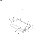
- Fig. 3 demonstrates a general perspective view of the electronic card mounted into the electronic card frame according to the present invention.
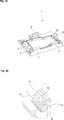
- Fig. 4a demonstrates an upper perspective view of the electronic card frame with latching means contact surfaces according to the present invention.
- Fig. 4b demonstrates an enlarged view of detail X as shown in Fig 4a.
- Fig. 5a demonstrates a planar top view of the electronic card as mounted.
- Fig. 5b demonstrates a cross-sectional view taken along line B-B of Fig 5a while the electronic card is being installed.
- Fig. 5c represents an enlarged view of first latching means contact surface shown in detail Y of Fig. 5b according to the present invention.
- the present invention relates to an electronic card frame (1) having first and second latching means (5, 6), the first latching means (5) being provided with support surfaces (8) serving for protecting circuit elements of an electronic card (2) in an electrical household appliance (10), such as a laundry drying machine, a laundry washing-drying machine, a dishwasher or a cooking appliance, during mounting of the electronic card (2).
- an electrical household appliance (10) such as a laundry drying machine, a laundry washing-drying machine, a dishwasher or a cooking appliance
- the household appliance (10) comprises an electronic card frame (1) with a pair of first latching means (5) disposed laterally at both sides of the electronic card frame (1).
- the first latching means (5) have support surfaces (8) providing a lineal contact with lateral edges (12) of the electronic card (2) during mounting of the same.
- the lineal contact arrangement serves to the purpose of preventing deformation of the electronic card (2) during the mounting procedure and ensures easy mounting thereof as delineated below.
- the electronic card (2) is installed into the electronic card frame (1) of the household appliance (10) by way of positioning the card first along a rotational axis (3) and then rotating the same in the direction of a mounting surface (4) so as to cover the surface. Accurate installation of the electronic card (2) into the frame is ensured by placement of the electronic card (2) in angular positon relative to the mounting surface (4). Two positioning arms (7) are located adjacent to the rotational axis (3) so as to determine the initial position of the electronic card (2) during the mounting of the same.
- the electronic card (2) During the rotational movement of the electronic card (2), it primarily contacts with the first latching means (5) that are perpendicularly positioned with respect to the rotational axis (3) of the card.
- the two first latching means (5) extending in parallel with the lateral edges of the electronic card (2) provides a continuously maintained lineal contact while the electronic card (2) sweeps the support surfaces (8) of the first latching means (5).
- the electronic card (2) is stabilized inside the electronic card frame (1) by way of engaging with the second latching means (6), which is disposed along the opposite edge of the card in parallel with the rotational axis (3).
- the support surfaces (8) of the first latching means (5) provide a lineal contact with the electronic card’s (2) lateral edge (12) so as to prevent possible deformations while one attempts at rotating the card in the direction of the mounting surface (4) because the card maintains a single-point contact relationship with the first latching means (5).
- a more practical structural arrangement is used such that support surfaces (8) ensure an easy and quick mounting for the electronic cards (2).
- the proposed structural arrangement is also advantageous in cases where it is difficult to install the card due to relatively small card dimensions or where inner area thereof is fully covered with circuit elements.
- the rotational movement of the electronic card (2) during the mounting of the same is assisted by the support surfaces (8) in the manner that the electronic card (2) remains in contact with the two lateral support surfaces (8) along a progressively changing lineal contact area (11).
- This advantageously provides that sufficient force can be exerted on the first latching means (5) thanks to the lineal contact area (11) so that the first latching means (5) allow rotational displacement of the card by flexing a certain amount externally, therefore enabling rotation of the electronic card (2).
- the progressively changing lineal contact area is obtainable due to the fact that the lateral edges of the support surface (8), i.e. the support surface first edge (13) and the support surface second edge (14) are not equal in length and the distance between two support surface first edges (13) of the two opposite first latching means (5) is greater than the distance between two support surface second edges (14) of the two opposite first latching means (5).
- This provides the effect that the electronic card (2), while being rotated, progressively presses onto the two opposite first latching means (5) because the distance in between progressively diminishes due to the inclined surface structure of the support surfaces (8).
- the non-rectangular arrangement of the support surface (8) primarily originates from the orientation of a support surface third edge (15), namely the upper edge of the support surface (8), which is inclined with respect to the lateral edge (12) of the electronic card (2) in the installed position of the same.
- a flexure area (9) in the form of an emptied intermediate space is provided so as to enhance the flexing effect of the first latching means (5) during rotational movement of the electronic card (2).
- the proposed electronic card frame (1) advantageously provides housing and stabilization for small electronic cards or for cards having small surface areas where use of additional connection elements may damage the circuit board.
- the lineal contact area (11) supports the movement of the electronic card (2) during the mounting procedure and furthermore prevents possible damages during the contact between the support surfaces (8) of the first latching means (5) and the electronic card (2).
- the present invention provides an electrical household appliance (10) comprising an electronic card frame (1) to receive and retain an electronic card (2).
- the electronic card frame (1) comprises a mounting surface (4) on which the electronic card (2) is mounted, a pair of first latching means (5) being disposed at both sides of the electronic card frame (1) and positioned perpendicularly with respect to a rotational axis (3) of the electronic card (2).
- the first latching means (5) are provided with support surfaces (8) establishing lineal contact with lateral edges (12) of the electronic card (2) during rotational movement of the same.
- the lateral edges (12) of the electronic card (2) maintain progressively changing lineal contact areas (11) with the two lateral support surfaces (8) of the first latching means (5) during rotational movement of the electronic card (2).
- the two first latching means (5) extend in parallel with the lateral edges (12) of the electronic card (2) and the support surfaces (8) thereof are inclined with respect to the mounting surface (4).
- the support surface (8) has two lateral edges in the form of a support surface first edge (13) and support surface second edge (14), the two edges having different lengths.
- the distance between two support surface first edges (13) of the two opposite first latching means (5) is greater than the distance between two support surface second edges (14) of the two opposite first latching means (5).
- the distance in between the two opposite first latching means (5) progressively diminishes while the electronic card (2) is rotated to be mounted.
- the support surface (8) has a non-rectangular structure.
- orientation of a support surface third edge (15) forming the upper edge of the support surface (8) is inclined with respect to the lateral edge (12) of the electronic card (2) in the installed position of the same.
- At least one positioning arm (7) is located adjacent to the rotational axis (3) so as to determine the initial position of the electronic card (2) during the mounting of the same whereby accurate installation of the electronic card (2) into the electronic card frame (1) is ensured by accurate placement of the electronic card (2).
- the electronic card (2) is stabilized inside the electronic card frame (1) by way of engaging with second latching means (6) disposed along an opposite edge of electronic card frame (1) in parallel with the rotational axis (3).
- a flexure area (9) is formed as an emptied intermediate space between the support surface (8) and a stem portion of the first latching means (5).
- the invention advantageously proposes a frame for electronic cards (2) in electrical household appliances (10) whereby easy mounting of the electronic card (2) into an electronic card frame (1) is ensured eliminating the necessity of using pins on the electronic card (2) surface and avoiding damaging of the card during installation.
- the invention also allows easier mounting in the case where the surface area of the electronic card (2) is too small so that no additional connection elements can be used.
Abstract
The present invention relates to a latching structure for an electronic card frame (1) to retain and protect electronic cards (2) in an electrical household appliance (10); whereby the household appliance (10) comprises an electronic card frame (1) to receive and retain an electronic card (2) and the electronic card frame (1) comprises a mounting surface (4) on which the electronic card (2) is mounted; a pair of latching means being disposed at both sides of the electronic card frame (1).
Description
The present invention relates to a latching structure in an electronic card frame to retain and protect electronic cards in stationary manner in an electrical household appliance.
In modern household appliances, electronic card trays are conventionally used to attach the circuit boards onto the suitable body portions of the appliance. User interface components such as encoders and switches being present on these circuit boards, it is possible that they are exerted a certain amount of force during use of the electronic card. It might also occasionally happen that the electronic card is subject to forces while moving the appliance.
The forces exerted on the card may result with the contact with surrounding conductive surfaces or may displace the card from where it is stationarily placed, possibly causing danger to safety. Therefore, to address such concerns, some electrical cards possess pin slots or intra-latching slots to preserve stability and safety. However, it might still occasionally happen that, because the surface area of the card is covered with a multitude of circuit elements, no intra-latching structures can be designed for stabilization to prevent damage on the circuit board.
An alternative approach is to install the electronic card body to the card holder tray by fixing first an edge thereof by means of stationary claws and then fastening the card body to the other latching members of the tray using claws perpendicular to and parallel with the axis of rotation during installation. The disadvantage associated with this procedure is that the circuit board may get damaged especially in case where the perpendicular latching members has a single-point contact relation with the electronic card, while the latter is rotated to be closed over the surface area of the electronic card frame.
In prior art applications, the above-specified disadvantages are avoided by way of designing card bodies with larger surface areas so as to have enough surface area accommodating slots for intra-latching members and pins on the card body itself. However, this in turn results with difficulties in the installation of the card into the appliance and furthermore causes an increase in the manufacturing costs.
A prior art publication in the technical field of the present invention may be referred to as US2011171846, disclosing a circuit card retained in a socket by a pair of movable arms engaging opposite sides of the card and securing the card in the socket. An arresting member is engaged with a portion of the card and engaged with the opposite sides and each of the movable arms, whereby the movable arms are maintained in engagement with the opposite sides of the card.
The present invention provides an electronic card frame to retain and protect an electronic card of an electrical household appliance in a stationary manner so as to avoid operational safety hazards, as defined by the characterizing features in Claim 1 and subsequent Claims.
Primary object of the present invention is to provide a frame for electronic cards in electrical household appliances to ensure easy mounting of the electronic card into the electronic card frame avoiding damaging of the card during installation. The invention also allows easier mounting in the case where the surface area of the electronic card is too small and eliminates the necessity of using pins on the electronic card surface.
The present invention proposes an electrical household appliance comprising an electronic card frame to receive and retain an electronic card. The electronic card frame has a pair of first latching means along the lateral edges. These first latching means extend perpendicular to a rotational axis along which the electronic card is rotatably mountable.
The first latching means have upper side support surfaces (8) extending towards the center of the electronic card frame with an inclination with respect to a planar mounting surface of the electronic card frame. The two support surfaces provide lineal contact with lateral edges of the electronic card during rotational movement of the same.
The lateral edges of the electronic card therefore maintain a progressively changing lineal contact area with both of the two support surfaces of the first latching means during rotational movement such that an adequate amount of force can be applied on the first latching means so as to flex the same a certain amount externally.
The support surfaces’ lateral edges have different lengths and the distance between two corresponding lateral edges of the two opposite first latching means progressively diminishes while the electronic card is rotated to be mounted.
The upper edge of the support surface is inclined with respect to the lateral edge of the electronic card in the installed position of the same, therefore providing the progressively changing in-between distance effect.
Accompanying drawings are given solely for the purpose of exemplifying an electric household appliance having an electronic card frame retaining an electronic card whose advantages over prior art were outlined above and will be explained in brief hereinafter.
The drawings are not meant to delimit the scope of protection as identified in the claims nor should they be referred to alone in an effort to interpret the scope identified in the claims without recourse to the technical disclosure in the description of the present invention.
Fig. 1 demonstrates a general perspective view of an electronic card frame with an electronic card being mounted into a household appliance according to the present invention.
Fig. 2 demonstrates a side cross-sectional view of the electronic card frame with the electronic card in an angled position in mounting state according to the present invention.
Fig. 3 demonstrates a general perspective view of the electronic card mounted into the electronic card frame according to the present invention.
Fig. 4a demonstrates an upper perspective view of the electronic card frame with latching means contact surfaces according to the present invention. Fig. 4b demonstrates an enlarged view of detail X as shown in Fig 4a.
Fig. 5a demonstrates a planar top view of the electronic card as mounted. Fig. 5b demonstrates a cross-sectional view taken along line B-B of Fig 5a while the electronic card is being installed. Fig. 5c represents an enlarged view of first latching means contact surface shown in detail Y of Fig. 5b according to the present invention.
The following numerals are assigned to different part number used in the detailed description:
- Electronic card frame
- Electronic card
- Rotational axis
- Mounting surface
- First latching means
- Second latching means
- Positioning arms
- Support surface
- Flexure area
- Household appliance
- Lineal contact area
- Lateral edge
- Support surface first edge
- Support surface second edge
- Support surface third edge
The present invention relates to an electronic card frame (1) having first and second latching means (5, 6), the first latching means (5) being provided with support surfaces (8) serving for protecting circuit elements of an electronic card (2) in an electrical household appliance (10), such as a laundry drying machine, a laundry washing-drying machine, a dishwasher or a cooking appliance, during mounting of the electronic card (2).
The household appliance (10) according to the present invention comprises an electronic card frame (1) with a pair of first latching means (5) disposed laterally at both sides of the electronic card frame (1). The first latching means (5) have support surfaces (8) providing a lineal contact with lateral edges (12) of the electronic card (2) during mounting of the same. The lineal contact arrangement serves to the purpose of preventing deformation of the electronic card (2) during the mounting procedure and ensures easy mounting thereof as delineated below.
The electronic card (2) is installed into the electronic card frame (1) of the household appliance (10) by way of positioning the card first along a rotational axis (3) and then rotating the same in the direction of a mounting surface (4) so as to cover the surface. Accurate installation of the electronic card (2) into the frame is ensured by placement of the electronic card (2) in angular positon relative to the mounting surface (4). Two positioning arms (7) are located adjacent to the rotational axis (3) so as to determine the initial position of the electronic card (2) during the mounting of the same.
During the rotational movement of the electronic card (2), it primarily contacts with the first latching means (5) that are perpendicularly positioned with respect to the rotational axis (3) of the card. The two first latching means (5) extending in parallel with the lateral edges of the electronic card (2) provides a continuously maintained lineal contact while the electronic card (2) sweeps the support surfaces (8) of the first latching means (5). Subsequently, the electronic card (2) is stabilized inside the electronic card frame (1) by way of engaging with the second latching means (6), which is disposed along the opposite edge of the card in parallel with the rotational axis (3).
The support surfaces (8) of the first latching means (5) provide a lineal contact with the electronic card’s (2) lateral edge (12) so as to prevent possible deformations while one attempts at rotating the card in the direction of the mounting surface (4) because the card maintains a single-point contact relationship with the first latching means (5). This causes that the electronic card (2) forced in the closing direction either damages the first latching means (5) or is damaged itself by the first latching means (5). It might even occur that the electronic card (2) breaks apart or gets stuck, in contact with the first latching means (5), let aside the fact that at least scratches will occur on the circuit board.
According to the invention, instead of using a plurality of additional pins for effecting mounting of the electronic card (2), a more practical structural arrangement is used such that support surfaces (8) ensure an easy and quick mounting for the electronic cards (2). The proposed structural arrangement is also advantageous in cases where it is difficult to install the card due to relatively small card dimensions or where inner area thereof is fully covered with circuit elements.
The rotational movement of the electronic card (2) during the mounting of the same is assisted by the support surfaces (8) in the manner that the electronic card (2) remains in contact with the two lateral support surfaces (8) along a progressively changing lineal contact area (11). This advantageously provides that sufficient force can be exerted on the first latching means (5) thanks to the lineal contact area (11) so that the first latching means (5) allow rotational displacement of the card by flexing a certain amount externally, therefore enabling rotation of the electronic card (2).
The progressively changing lineal contact area is obtainable due to the fact that the lateral edges of the support surface (8), i.e. the support surface first edge (13) and the support surface second edge (14) are not equal in length and the distance between two support surface first edges (13) of the two opposite first latching means (5) is greater than the distance between two support surface second edges (14) of the two opposite first latching means (5). This provides the effect that the electronic card (2), while being rotated, progressively presses onto the two opposite first latching means (5) because the distance in between progressively diminishes due to the inclined surface structure of the support surfaces (8). The non-rectangular arrangement of the support surface (8) primarily originates from the orientation of a support surface third edge (15), namely the upper edge of the support surface (8), which is inclined with respect to the lateral edge (12) of the electronic card (2) in the installed position of the same.
A flexure area (9) in the form of an emptied intermediate space is provided so as to enhance the flexing effect of the first latching means (5) during rotational movement of the electronic card (2).
The proposed electronic card frame (1) advantageously provides housing and stabilization for small electronic cards or for cards having small surface areas where use of additional connection elements may damage the circuit board. The lineal contact area (11) supports the movement of the electronic card (2) during the mounting procedure and furthermore prevents possible damages during the contact between the support surfaces (8) of the first latching means (5) and the electronic card (2).
In summary, the present invention provides an electrical household appliance (10) comprising an electronic card frame (1) to receive and retain an electronic card (2). The electronic card frame (1) comprises a mounting surface (4) on which the electronic card (2) is mounted, a pair of first latching means (5) being disposed at both sides of the electronic card frame (1) and positioned perpendicularly with respect to a rotational axis (3) of the electronic card (2).
In one embodiment of the present invention, the first latching means (5) are provided with support surfaces (8) establishing lineal contact with lateral edges (12) of the electronic card (2) during rotational movement of the same.
In a further embodiment of the present invention, the lateral edges (12) of the electronic card (2) maintain progressively changing lineal contact areas (11) with the two lateral support surfaces (8) of the first latching means (5) during rotational movement of the electronic card (2).
In a further embodiment of the present invention, the two first latching means (5) extend in parallel with the lateral edges (12) of the electronic card (2) and the support surfaces (8) thereof are inclined with respect to the mounting surface (4).
In a further embodiment of the present invention, the support surface (8) has two lateral edges in the form of a support surface first edge (13) and support surface second edge (14), the two edges having different lengths.
In a further embodiment of the present invention, the distance between two support surface first edges (13) of the two opposite first latching means (5) is greater than the distance between two support surface second edges (14) of the two opposite first latching means (5).
In a further embodiment of the present invention, the distance in between the two opposite first latching means (5) progressively diminishes while the electronic card (2) is rotated to be mounted.
In a further embodiment of the present invention, the support surface (8) has a non-rectangular structure.
In a further embodiment of the present invention, orientation of a support surface third edge (15) forming the upper edge of the support surface (8) is inclined with respect to the lateral edge (12) of the electronic card (2) in the installed position of the same.
In a further embodiment of the present invention, at least one positioning arm (7) is located adjacent to the rotational axis (3) so as to determine the initial position of the electronic card (2) during the mounting of the same whereby accurate installation of the electronic card (2) into the electronic card frame (1) is ensured by accurate placement of the electronic card (2).
In a further embodiment of the present invention, the electronic card (2) is stabilized inside the electronic card frame (1) by way of engaging with second latching means (6) disposed along an opposite edge of electronic card frame (1) in parallel with the rotational axis (3).
In a further embodiment of the present invention, a flexure area (9) is formed as an emptied intermediate space between the support surface (8) and a stem portion of the first latching means (5).
Therefore, the invention advantageously proposes a frame for electronic cards (2) in electrical household appliances (10) whereby easy mounting of the electronic card (2) into an electronic card frame (1) is ensured eliminating the necessity of using pins on the electronic card (2) surface and avoiding damaging of the card during installation. The invention also allows easier mounting in the case where the surface area of the electronic card (2) is too small so that no additional connection elements can be used.
Claims (11)
- A household appliance (10) comprising an electronic card frame (1) to receive and retain an electronic card (2), the electronic card frame (1) comprising a mounting surface (4) on which the electronic card (2) is mounted, a pair of first latching means (5) being disposed at both sides of the electronic card frame (1) and positioned perpendicularly with respect to a rotational axis (3) of the electronic card (2), characterized in that the first latching means (5) are provided with support surfaces (8) establishing lineal contact with lateral edges (12) of the electronic card (2) during rotational movement of the same.
- A household appliance (10) as in Claim 1, characterized in that the lateral edges (12) of the electronic card (2) maintain progressively changing lineal contact areas (11) with the two lateral support surfaces (8) of the first latching means (5) during rotational movement of the electronic card (2).
- A household appliance (10) as in Claim 1 or 2, characterized in that the two first latching means (5) extend in parallel with the lateral edges (12) of the electronic card (2) and the support surfaces (8) thereof are inclined with respect to the mounting surface (4).
- A household appliance (10) as in any preceding claims, characterized in that the support surface (8) has two lateral edges in the form of a support surface first edge (13) and support surface second edge (14), the two edges having different lengths.
- A household appliance (10) as in Claim 4, characterized in that the distance between two support surface first edges (13) of the two opposite first latching means (5) is greater than the distance between two support surface second edges (14) of the two opposite first latching means (5).
- A household appliance (10) as in Claim 5, characterized in that the distance in between the two opposite first latching means (5) progressively diminishes while the electronic card (2) is rotated to be mounted.
- A household appliance (10) as in any one of the claims 4 to 6, characterized in that the support surface (8) has a non-rectangular structure.
- A household appliance (10) as in any one of the claims 4 to 7, characterized in that orientation of a support surface third edge (15) forming the upper edge of the support surface (8) is inclined with respect to the lateral edge (12) of the electronic card (2) in the installed position of the same.
- A household appliance (10) as in any preceding claims, characterized in that at least one positioning arm (7) is located adjacent to the rotational axis (3) so as to determine the initial position of the electronic card (2) during the mounting of the same whereby accurate installation of the electronic card (2) into the electronic card frame (1) is ensured by accurate placement of the electronic card (2).
- A household appliance (10) as in any preceding claims, characterized in that the electronic card (2) is stabilized inside the electronic card frame (1) by way of engaging with second latching means (6) disposed along an opposite edge of electronic card frame (1) in parallel with the rotational axis (3).
- A household appliance (10) as in any preceding claims, characterized in that a flexure area (9) is formed as an emptied intermediate space between the support surface (8) and a stem portion of the first latching means (5)
Priority Applications (1)
| Application Number | Priority Date | Filing Date | Title |
|---|---|---|---|
| PCT/EP2015/051751 WO2016119844A1 (en) | 2015-01-29 | 2015-01-29 | Electronic card frame retaining a household appliance electronic card |
Applications Claiming Priority (1)
| Application Number | Priority Date | Filing Date | Title |
|---|---|---|---|
| PCT/EP2015/051751 WO2016119844A1 (en) | 2015-01-29 | 2015-01-29 | Electronic card frame retaining a household appliance electronic card |
Publications (1)
| Publication Number | Publication Date |
|---|---|
| WO2016119844A1 true WO2016119844A1 (en) | 2016-08-04 |
Family
ID=52440664
Family Applications (1)
| Application Number | Title | Priority Date | Filing Date |
|---|---|---|---|
| PCT/EP2015/051751 WO2016119844A1 (en) | 2015-01-29 | 2015-01-29 | Electronic card frame retaining a household appliance electronic card |
Country Status (1)
| Country | Link |
|---|---|
| WO (1) | WO2016119844A1 (en) |
Cited By (7)
| Publication number | Priority date | Publication date | Assignee | Title |
|---|---|---|---|---|
| WO2018103951A1 (en) | 2016-12-07 | 2018-06-14 | Arcelik Anonim Sirketi | A dishwasher comprising a card holder |
| WO2018121926A1 (en) | 2016-12-28 | 2018-07-05 | Arcelik Anonim Sirketi | A dishwasher |
| CN108478151A (en) * | 2018-04-28 | 2018-09-04 | 珠海格力电器股份有限公司 | A kind of electric appliance box mounting structure, electrical appliance kit and dish-washing machine |
| WO2019228732A1 (en) | 2018-05-31 | 2019-12-05 | Arcelik Anonim Sirketi | A card holder suitable for use in household appliances |
| WO2020126463A1 (en) * | 2018-12-19 | 2020-06-25 | Arcelik Anonim Sirketi | A control panel and an electrical household appliance comprising the control panel |
| WO2020136257A1 (en) | 2018-12-27 | 2020-07-02 | Arcelik Anonim Sirketi | A household appliance comprising a cable protector |
| EP3792385A1 (en) | 2019-09-10 | 2021-03-17 | Arçelik Anonim Sirketi | An electrical household appliance comprising a circuit board |
Citations (5)
| Publication number | Priority date | Publication date | Assignee | Title |
|---|---|---|---|---|
| DE19651821A1 (en) * | 1996-12-13 | 1998-06-18 | Miele & Cie | Washing machine, etc. |
| US20110171846A1 (en) | 2010-01-11 | 2011-07-14 | Dell Products L.P. | Circuit Card Latching Arm Arresting Apparatus |
| EP2442035A2 (en) * | 2010-10-12 | 2012-04-18 | Diehl AKO Stiftung & Co. KG | Control panel for an electric domestic appliance |
| EP2458060A1 (en) * | 2010-11-29 | 2012-05-30 | Electrolux Home Products Corporation N.V. | Control-panel assembly for household appliances and household appliance provided with such control-panel assembly |
| EP2644765A2 (en) * | 2012-03-27 | 2013-10-02 | Samsung Electronics Co., Ltd | Washing Machine |
-
2015
- 2015-01-29 WO PCT/EP2015/051751 patent/WO2016119844A1/en active Application Filing
Patent Citations (5)
| Publication number | Priority date | Publication date | Assignee | Title |
|---|---|---|---|---|
| DE19651821A1 (en) * | 1996-12-13 | 1998-06-18 | Miele & Cie | Washing machine, etc. |
| US20110171846A1 (en) | 2010-01-11 | 2011-07-14 | Dell Products L.P. | Circuit Card Latching Arm Arresting Apparatus |
| EP2442035A2 (en) * | 2010-10-12 | 2012-04-18 | Diehl AKO Stiftung & Co. KG | Control panel for an electric domestic appliance |
| EP2458060A1 (en) * | 2010-11-29 | 2012-05-30 | Electrolux Home Products Corporation N.V. | Control-panel assembly for household appliances and household appliance provided with such control-panel assembly |
| EP2644765A2 (en) * | 2012-03-27 | 2013-10-02 | Samsung Electronics Co., Ltd | Washing Machine |
Cited By (7)
| Publication number | Priority date | Publication date | Assignee | Title |
|---|---|---|---|---|
| WO2018103951A1 (en) | 2016-12-07 | 2018-06-14 | Arcelik Anonim Sirketi | A dishwasher comprising a card holder |
| WO2018121926A1 (en) | 2016-12-28 | 2018-07-05 | Arcelik Anonim Sirketi | A dishwasher |
| CN108478151A (en) * | 2018-04-28 | 2018-09-04 | 珠海格力电器股份有限公司 | A kind of electric appliance box mounting structure, electrical appliance kit and dish-washing machine |
| WO2019228732A1 (en) | 2018-05-31 | 2019-12-05 | Arcelik Anonim Sirketi | A card holder suitable for use in household appliances |
| WO2020126463A1 (en) * | 2018-12-19 | 2020-06-25 | Arcelik Anonim Sirketi | A control panel and an electrical household appliance comprising the control panel |
| WO2020136257A1 (en) | 2018-12-27 | 2020-07-02 | Arcelik Anonim Sirketi | A household appliance comprising a cable protector |
| EP3792385A1 (en) | 2019-09-10 | 2021-03-17 | Arçelik Anonim Sirketi | An electrical household appliance comprising a circuit board |
Similar Documents
| Publication | Publication Date | Title |
|---|---|---|
| WO2016119844A1 (en) | Electronic card frame retaining a household appliance electronic card | |
| KR101492759B1 (en) | Contact element for plug-in connector socket | |
| US9797926B2 (en) | Contact and electrical connection testing apparatus using the same | |
| CN108541176B (en) | Bracket for fixing electronic device and mechanism for fixing electronic device | |
| JP5790681B2 (en) | Electrical connector | |
| KR101334237B1 (en) | Electric contact terminal | |
| KR100894436B1 (en) | Universal connector | |
| US10312617B2 (en) | Electrical connector including a metal housing and a flexible flat transmission component | |
| KR102472828B1 (en) | Electrical connection unit between two electronic boards | |
| EP3132505B1 (en) | Electrical grounding component and corresponding electronic board and electronic apparatus | |
| US7593240B2 (en) | Fixing mechanism for fixing a switch and related electronic device | |
| JP3909869B2 (en) | Tumbler switch | |
| JP2017515268A5 (en) | ||
| JP4800404B2 (en) | Electrical connector | |
| US20070114059A1 (en) | Shielding member | |
| KR101400747B1 (en) | A terminal contact | |
| KR101133189B1 (en) | Clips for fixing shield covers | |
| KR20160080668A (en) | Board connecting terminal button switch modules | |
| KR102219174B1 (en) | Electronic components mounting apparatus | |
| KR102545537B1 (en) | Connector assembly | |
| JP5948622B2 (en) | Panel mounting bracket | |
| JP2011034902A (en) | Electric connector | |
| KR102483532B1 (en) | Case for electronic component | |
| KR100382342B1 (en) | Controller structure of washer | |
| KR200493738Y1 (en) | Bracket for fixing connector and pcb connector having the same |
Legal Events
| Date | Code | Title | Description |
|---|---|---|---|
| 121 | Ep: the epo has been informed by wipo that ep was designated in this application |
Ref document number: 15701966 Country of ref document: EP Kind code of ref document: A1 |
|
| NENP | Non-entry into the national phase |
Ref country code: DE |
|
| 122 | Ep: pct application non-entry in european phase |
Ref document number: 15701966 Country of ref document: EP Kind code of ref document: A1 |