WO2016117227A1 - 磁石埋込型回転電機 - Google Patents
磁石埋込型回転電機 Download PDFInfo
- Publication number
- WO2016117227A1 WO2016117227A1 PCT/JP2015/083843 JP2015083843W WO2016117227A1 WO 2016117227 A1 WO2016117227 A1 WO 2016117227A1 JP 2015083843 W JP2015083843 W JP 2015083843W WO 2016117227 A1 WO2016117227 A1 WO 2016117227A1
- Authority
- WO
- WIPO (PCT)
- Prior art keywords
- magnet
- rotor
- rotor core
- magnets
- same polarity
- Prior art date
- Legal status (The legal status is an assumption and is not a legal conclusion. Google has not performed a legal analysis and makes no representation as to the accuracy of the status listed.)
- Ceased
Links
Images




Classifications
-
- H—ELECTRICITY
- H02—GENERATION; CONVERSION OR DISTRIBUTION OF ELECTRIC POWER
- H02K—DYNAMO-ELECTRIC MACHINES
- H02K1/00—Details of the magnetic circuit
- H02K1/06—Details of the magnetic circuit characterised by the shape, form or construction
- H02K1/22—Rotating parts of the magnetic circuit
-
- H—ELECTRICITY
- H02—GENERATION; CONVERSION OR DISTRIBUTION OF ELECTRIC POWER
- H02K—DYNAMO-ELECTRIC MACHINES
- H02K1/00—Details of the magnetic circuit
- H02K1/06—Details of the magnetic circuit characterised by the shape, form or construction
- H02K1/22—Rotating parts of the magnetic circuit
- H02K1/27—Rotor cores with permanent magnets
Definitions
- the present invention relates to a magnet-embedded rotating electrical machine including a rotor having a rotor core in which permanent magnets are embedded, and a stator disposed to face the rotor.
- Rotating electric machine is a general term for an electric motor, a generator, and an electric motor / generator.
- the electric motor is called an IPM (Interior Permanent Magnet) motor.
- an electric motor having a rotor in which a permanent magnet is attached to the surface of a rotor core is called a SPM (Surface Permanent Magnet) motor.
- the IPM motor and the SPM motor are collectively referred to as a PM motor.
- Patent Document 1 discloses a rotating electrical machine in which a retaining ring is arranged on the surface side of a permanent magnet.
- the higher the output of the rotating electrical machine and the larger the rotating electrical machine the larger the size of the permanent magnet, making it more difficult to arrange on the rotor core. Further, when the size of the permanent magnet is increased, there is a problem that the centrifugal force acting on the permanent magnet is increased.
- the IPM structure in order to give the rotor core strength to withstand centrifugal force, it is necessary to increase the radial width of the rotor core in the magnetic flux short circuit that is the portion between the outer peripheral surface of the rotor core and the permanent magnet. However, if the width of the magnetic flux short-circuit path is increased, the short-circuit magnetic flux flowing in the rotor core increases, so that the magnetic flux decreases in the gap between the stator and the rotor, and the torque decreases.
- An object of the present invention is to provide a magnet-embedded rotating electrical machine in which permanent magnets can be easily arranged on a rotor core and torque reduction can be minimized.
- An embedded magnet type rotating electrical machine includes a rotor having a rotor core in which two sets of permanent magnets are embedded, a stator disposed to face the rotor, An output shaft made of a magnetic material inserted through the center, and each of the two sets of permanent magnets includes three or more homopolar magnets arranged adjacent to each other along the circumferential direction of the rotor
- a magnet insertion hole for accommodating the magnet of the same polarity is formed for each magnet of the same polarity, and in the rotor core, the magnets of the same polarity of the same set are respectively accommodated and adjacent to each other.
- the portion between the magnet insertion holes is a part between the same poles, and the part between the magnet insertion holes adjacent to each other and containing the magnets of the same polarity different from each other, In the circumferential direction of the rotor
- the thickness of the same interpolar portion characterized in that thinner than the thickness of the different interpolar portion
- FIG. 1 is a cross-sectional view of a magnet-embedded rotating electrical machine.
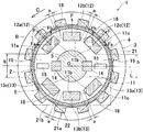
- 2 is a cross-sectional view taken along the line II-II in FIG. 1, and is a cross-sectional view of the magnet-embedded rotating electrical machine according to the first embodiment.
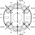
- FIG. 3 is an enlarged view of a main part B of FIG.
- FIG. 4 is a diagram illustrating a result of analyzing the relationship between the mechanical angle and the torque.
- FIG. 5 is a cross-sectional view of the magnet-embedded rotating electrical machine according to the second embodiment.
- FIG. 6 is a cross-sectional view of a magnet-embedded rotating electrical machine according to the third embodiment.
- the magnet-embedded rotary electric machine of the present invention can be used as an electric motor for various machines such as an in-vehicle electric motor and a generator mounted on an aircraft, a generator, and an electric motor / generator.
- the magnet-embedded rotary electric machine according to the first embodiment of the present invention is an IPM motor.
- the IPM motor 1 includes a rotor (rotor) 2 and a rotor on the radially outer side of the rotor 2. 2, a cylindrical stator (stator) 3 disposed opposite to the rotor 2, an output shaft 5 inserted through the center of the rotor 2, and a protective tube 4 attached to the outer peripheral surface of the rotor 2. is doing.
- the rotor 2 is disposed in the stator 3 so that its axis coincides with the axis of the stator 3 (coaxial).
- the rotor 2 and the stator 3 are accommodated in a casing (not shown).
- the rotor 2 has a cylindrical rotor core 11, two sets of permanent magnets 12 and 13 embedded in the rotor core 11, and a gap 15 provided in the rotor core 11. That is, the IPM motor 1 of this embodiment has two poles.
- the rotor 2 can rotate in the C direction shown in FIG. 2 and in the opposite direction.
- the rotor core 11 is formed, for example, by laminating ring plate-shaped electromagnetic steel plates in the axial direction. In the center of the rotor core 11, a hole 11a penetrating in the axial center (rotating axis) direction is formed. An output shaft (shaft) 5 for extracting the rotation of the rotor 2 to the outside is inserted into the hole 11a.
- the rotor core 11 is fixed to the output shaft 5 with a parallel key 14.
- the output shaft 5 is rotatably supported by a bearing (not shown).
- the rotor core 11 may be fixed to the output shaft 5 by making a part of the rotor core 11 convex and making a part of the output shaft 5 concave and engaging them.
- the permanent magnet 12 is composed of three magnets 12a, 12b, and 12c having the same polarity arranged adjacent to each other along the circumferential direction of the rotor 2.
- the permanent magnet 13 is composed of three magnets 13 a, 13 b, and 13 c having the same polarity arranged adjacent to each other along the circumferential direction of the rotor 2.
- magnet fitting holes 11b for accommodating magnets 12a, 12b, 12c, 13a, 13b, 13c having the same polarity are formed for each magnet having the same polarity.
- three magnet fitting holes 11 b for accommodating each of the three homopolar magnets 12 a, 12 b, 12 c constituting the permanent magnet 12 and the permanent magnet 13 are constituted.
- Three magnet insertion holes 11b for accommodating each of the three magnets 13a, 13b, 13c having the same polarity are formed.
- Each magnet fitting hole 11b penetrates the rotor core 11 in the axial direction.
- Three magnets 12a, 12b, 12c having the same polarity and three magnets 13a, 13b, 13c having the same polarity are respectively fitted in the six magnet fitting holes 11b.
- the two sets of permanent magnets 12 and 13 are neodymium magnets or the like, and are fitted into the magnet fitting holes 11b of the rotor core 11 to form the magnetic poles of the rotor 2 (rotor core 11).
- the permanent magnet 12 and the permanent magnet 13 are arranged so that the magnetic poles adjacent to each other in the circumferential direction of the rotor 2 are opposite to each other, that is, the S pole and the N pole are alternately arranged in the circumferential direction on the outer circumferential surface of the rotor core 11. It fits in each magnet fitting hole 11b so that it may line up.
- the surfaces of the three same-polarity magnets 12a, 12b, and 12c in the same set that face the center of the rotor core 11 are S poles, and the shape thereof is a plane. Further, the surfaces of the three same-polarity magnets 12a, 12b, and 12c in the same set facing the stator 3 are each N-poles, and the shape thereof is a plane. Therefore, the surface facing the center of the rotor core 11 and the surface facing the stator 3 in the magnet insertion hole 11b that accommodates the magnets 12a, 12b, and 12c having the same polarity are made flat.
- the shape of the surface of the magnets 12a, 12b, and 12c having the same polarity is not limited to a flat surface, and may be a curved surface.
- the surfaces of the three same-polarity magnets 13a, 13b, and 13c in the same set that face the center of the rotor core 11 are each N-poles, and the shape thereof is a plane.
- the surfaces of the three same-polarity magnets 13a, 13b, and 13c in the same set that face the stator 3 are S poles, and the shape thereof is a plane. Therefore, the surface facing the center of the rotor core 11 and the surface facing the stator 3 in the magnet insertion hole 11b that accommodates the magnets 13a, 13b, and 13c having the same polarity are flat.
- the shape of the surface of the magnets 13a, 13b, and 13c having the same polarity is not limited to a flat surface, and may be a curved surface.
- a portion of the rotor core 11 between the outer peripheral surface of the rotor core 11 and the magnet insertion hole 11b is a magnetic flux short circuit 11c in which the magnetic flux is short-circuited in the rotor core 11.
- the short-circuiting of the magnetic flux means that the magnetic flux emitted from the N pole does not reach the gap 6 between the stator 3 and the rotor 2 and enters the S pole as it is through the rotor core 11.
- the three same-polarity magnets 12a, 12b, and 12c constituting the permanent magnet 12 are disposed adjacently along the circumferential direction of the rotor 2 so that the same-polarity magnets do not interfere with the output shaft 5. be able to. Moreover, by dividing the permanent magnet 12 into three magnets 12a, 12b, and 12c having the same polarity, the size of the magnets 12a, 12b, and 12c having the same polarity is reduced and the arrangement on the rotor core 11 is easy. become. Therefore, the permanent magnet 12 can be easily disposed on the rotor core 11. This effect becomes more remarkable as the size of the IPM motor 1 increases. The same applies to the three same-polarity magnets 13a, 13b, and 13c constituting the permanent magnet 13.
- the centrifugal force acting on the magnets 12a, 12b, 12c per magnet when the rotor 2 rotates. Can be reduced. Therefore, when the centrifugal force of the magnets 12a, 12b, and 12c having the same polarity is received at the portion around the magnet fitting hole 11b in the rotor core 11, the stress acting on the magnetic flux short circuit 11c can be reduced. As a result, since the thickness of the magnetic flux short circuit 11c in the radial direction of the rotor core 11 can be reduced, the short circuit magnetic flux flowing through the magnetic flux short circuit 11c can be reduced.
- the output shaft 5 is made of a magnetic material.
- the magnetic material refers to a ferromagnetic material such as iron.
- FIG. 3 which is an enlarged view of the main part B of FIG. 2, the output shaft 5 is made of a magnetic material, so that the magnetic flux flowing between the two sets of permanent magnets 12 and 13 in the rotor core 11 pass.
- the magnetic flux easily flows between the two sets of permanent magnets 12 and 13 in the rotor core 11. Accordingly, since the magnetic flux flowing between the two sets of permanent magnets 12 and 13 in the rotor core 11 increases, the magnetic flux that is short-circuited in the rotor core 11 can be reduced. Thereby, since the magnetic flux which flows through the space
- Each of the magnet insertion holes 11b accommodates magnets 12a, 12b, 12c, 13a, 13b, and 13c having the same polarity so that gaps are formed on both sides of the magnet having the same polarity in the circumferential direction of the rotor 2. It may be. When these gaps are provided, the magnetic flux that is short-circuited in the rotor core 11 can be reduced.
- the air gap 15 is provided between the magnet fitting holes 11b and 11b adjacent to each other in the rotor core 11 which accommodate different sets of magnets of the same polarity. Specifically, the gap 15 is between the magnet insertion hole 11b that accommodates the magnet 12a of the same polarity and the magnet insertion hole 11b that accommodates the magnet 13c of the same polarity, and the magnet insertion that accommodates the magnet 12c of the same polarity. It is provided between the hole 11b and the magnet insertion hole 11b for accommodating the magnet 13a having the same polarity.
- the space 15 is filled with air.
- the short-circuit magnetic flux flowing between the two sets of permanent magnets 12 and 13 along the circumferential direction of the rotor 2 can be reduced in the rotor core 11.
- gap part 6 between the stator 3 and the rotor 2 increases, the fall of a torque can further be suppressed.
- end plates 16 are provided at both ends of the rotor 2 in the axial direction.
- the pair of end plates 16 are fixed to the rotor 2 by bolts 17 that penetrate the rotor core 11 in the axial direction.
- bolt holes provided through the rotor core 11 can be suitably used as the gaps 15.
- a non-magnetic material may be embedded between the magnet insertion holes 11 b and 11 b adjacent to each other by accommodating different sets of magnets having the same polarity.
- the nonmagnetic material include metals such as aluminum, SUS, and brass, and adhesives.
- stator 3 As shown in FIGS. 1 and 2, the stator 3 includes a cylindrical stator core 21 and a winding 22 wound around the inner peripheral surface of the stator core 21.
- the stator core 21 is formed by, for example, laminating a plurality of electromagnetic steel plates (silicon steel plates or the like) in the axial direction. On the inner peripheral surface of the stator core 21, slots 21a and teeth 21b are formed alternately and continuously along the circumferential direction. A winding 22 is wound around the tooth 21b. A rotating magnetic field is formed by supplying a current having a predetermined phase difference to the windings 22 wound around the plurality of teeth 21b. Thereby, magnet torque and reluctance torque are generated in the rotor 2, and the rotor 2 rotates.
- the reluctance torque is generated when the rotor 2 rotates with respect to the stator 3 in an attempt to flow a magnetic flux in a place where the magnetic resistance is difficult to flow, that is, where the magnetic resistance is difficult to flow. Torque.
- the protective tube 4 is made of an insulator. By mounting such a protective tube 4 on the outer peripheral surface of the rotor core 11 by shrink fitting or the like, the strength of the rotor core 11 is improved and the scattering of permanent magnets is prevented.
- the protective tube 4 may be made of a metal, a magnetic material, a magnetic material with low permeability, or the like.
- the same pair of magnets of the same polarity are accommodated, and the portion between the adjacent magnet fitting holes 11 b, 11 b is the same pole portion 18, and different sets of the same poles.
- the portion between the magnet insertion holes 11b, 11b adjacent to each other and accommodating the magnets is referred to as an interpolar portion 19.
- the thickness a of the interpolar portion 18 is set to be thinner than the thickness b of the interpolar portion 19.
- the thickness a of the permanent magnet 12 is defined between the magnet insertion hole 11b that accommodates the magnet 12a of the same polarity and the magnet insertion hole 11b that accommodates the magnet 12b of the same polarity in the circumferential direction of the rotor 2. And a portion between the same poles, which is a portion between the magnet insertion hole 11b for accommodating the magnet 12b of the same polarity and the magnet insertion hole 11b for receiving the magnet 12c of the same polarity.
- the thickness is 18.
- the thickness b is the thickness of the interpolar part 19 that is a part between the magnet insertion hole 11b that accommodates the magnet 12a of the same polarity and the magnet insertion hole 11b that accommodates the magnet 13c of the same polarity, and the magnet of the same polarity It is the thickness of the part 14 between different poles which is a part between the magnet fitting hole 11b which accommodates 12c, and the magnet fitting hole 11b which accommodates the magnet 13a of the same polarity. And thickness a is set thinner than thickness b. The same applies to the magnet insertion holes 11b that house the three same-polarity magnets 13a, 13b, and 13c. That is, six magnet insertion holes 11b are formed in the rotor core 11 so that the thickness a of the interpolar portion 18 is thinner than the thickness b of the interpolar portion 19.
- the centrifugal force F acting on the magnets 12 a, 12 b, 12 c having the same polarity is orthogonal to the component Fa parallel to the direction passing from the center O of the rotor core 11 to the interpolar portion 19. It decomposes into component Fb.
- the sum of the orthogonal components Fb of each of the same-polarity magnets 12a, 12b, 12c is greater than the sum of the parallel components Fa of each of the same-polarity magnets 12a, 12b, 12c. . Therefore, when the centrifugal force of the magnet of the same polarity is received at the portion around the magnet fitting hole 11b in the rotor core 11, the bending stress acting on the different pole portion 19 side of the magnet fitting hole 11b becomes large.
- the combined stress of the bending stress and the tensile stress increases on the side 19 between the different poles of the magnet insertion hole 11b.
- this stress can be absorbed.
- the bending stress acting on the side 18 between the same poles of the magnet insertion hole 11b is reduced. This stress can be absorbed. Thereby, the strength of the rotor core 11 can be maintained.
- the short-circuit magnetic flux flowing between the same-polarity magnets 12 a and 12 b can be reduced. Thereby, the fall of torque can be suppressed.
- the thickness b of the interpolar portion 19 can be increased as the thickness a of the interpolar portion 18 is reduced. Therefore, the attractive force acting on the iron constituting the interpolar portion 19 is stronger than the attractive force acting on the iron constituting the interpolar portion 18. Thereby, a torque different from the magnet torque can be obtained. Furthermore, since the space
- the torque reduction can be minimized by making the thickness a of the interpolar portion 18 thinner than the thickness b of the interpolar portion 19.
- FIG. 4 shows the result of analyzing the relationship between the mechanical angle and the torque when the thickness a of the interpolar part 18 is varied.
- the mechanical angle is changed by 180 degrees in the C direction with the straight line L being 0 °.
- the straight line L is an imaginary line that passes through the center O of the rotor core 11 (rotor 2) and is located between the permanent magnet 12 and the permanent magnet 13. It can be seen that the torque is improved by reducing the thickness a of the interpolar portion 18.
- the three same-polarity magnets constituting the permanent magnet are arranged adjacently along the circumferential direction of the rotor 2. By doing so, it is possible to prevent a magnet having the same polarity from interfering with the output shaft 5. Further, by dividing the permanent magnet into three magnets with the same polarity, the size of the magnets with the same polarity per one is reduced, and the arrangement on the rotor core 11 is facilitated. Therefore, a permanent magnet can be easily disposed on the rotor core 11. This effect becomes more remarkable as the size of the IPM motor 1 increases.
- the centrifugal force acting on the magnets with the same polarity can be reduced. Therefore, when the centrifugal force of the magnet having the same polarity is received at the portion around the magnet fitting hole 11b in the rotor core 11, it acts on the magnetic flux short circuit 11c that is the portion between the outer peripheral surface of the rotor core 11 and the magnet having the same polarity. Stress to be reduced. As a result, since the thickness of the magnetic flux short circuit 11c in the radial direction of the rotor core 11 can be reduced, the short circuit magnetic flux flowing through the magnetic flux short circuit 11c can be reduced. Thereby, since the magnetic flux which flows through the space
- the output shaft 5 is made of a magnetic material, the magnetic flux flowing between the two sets of permanent magnets 12 and 13 passes through the output shaft 5 in the rotor core 11. As a result, the magnetic flux easily flows between the two sets of permanent magnets 12 and 13 in the rotor core 11. And since the magnetic flux which flows between 2 sets of permanent magnets 12 and 13 in the rotor core 11 increases, the magnetic flux which short-circuits in the rotor core 11 can be decreased. Thereby, since the magnetic flux which flows through the space
- the same set of magnets of the same polarity are accommodated, the portion between the adjacent magnet fitting holes 11b, 11b is accommodated between the same polarity portions 18, and the magnets of the same polarity of different sets are accommodated. Then, when the portion between the magnet insertion holes 11b, 11b adjacent to each other is used as a portion 19 between different poles, the thickness a of the portion 18 between the same poles in the circumferential direction of the rotor 2 is set to the thickness of the portion 19 between the different poles. It is set thinner than b.
- the centrifugal force F acting on the magnet having the same polarity is decomposed into a component Fa parallel to a direction passing through the interpolar portion 19 from the center O of the rotor core 11 and a component Fb orthogonal thereto.
- the sum of the orthogonal components Fb of the same set of same-pole magnets is larger than the sum of the parallel components Fa of each of the same-pole same-pole magnets. Therefore, when the centrifugal force of the magnet of the same polarity is received at the portion around the magnet fitting hole 11b in the rotor core 11, the bending stress acting on the different pole portion 19 side of the magnet fitting hole 11b becomes large.
- the stress which combined bending stress and tensile stress becomes large in the part 19 between different poles of the magnet fitting hole 11b.
- this stress can be absorbed.
- the stress concentration on the side 19 between the different poles of the magnet insertion hole 11b the bending stress acting on the side 18 between the same poles of the magnet insertion hole 11b is reduced. This stress can be absorbed. Thereby, the strength of the rotor core 11 can be maintained.
- the thickness a of the interpolar part 18 it is possible to reduce the short-circuit magnetic flux that flows between the same-polarity magnets.
- the thickness b of the interpolar portion 19 can be increased as the thickness a of the interpolar portion 18 is reduced, the attractive force acting on the iron constituting the interpolar portion 19 is reduced between the same poles. The suction force acting on the iron constituting the portion 18 becomes stronger. Thereby, a torque different from the magnet torque can be obtained.
- interval of two sets of permanent magnets 12 and 13 becomes wide by making thickness b of the different pole part 19 thick, a big reluctance torque can be obtained. As a result, torque reduction can be minimized.
- the permanent magnets 12 and 13 can be easily arranged on the rotor core 11, and the torque reduction can be minimized.
- a gap 15 or a nonmagnetic material is provided between the magnet fitting holes 11b, 11b adjacent to each other in the rotor core 11 which accommodate different sets of magnets of the same polarity. For this reason, in the rotor core 11, the short circuit magnetic flux which flows between two sets of permanent magnets 12 and 13 along the circumferential direction of the rotor 2 can be reduced. Thereby, since the magnetic flux which flows through the space
- IPM motor magnet embedded rotary electric machine
- the IPM motor 201 of this embodiment is different from the IPM motor 1 of the first embodiment in that each of the two sets of permanent magnets 12 and 13 is shown in FIG. 5 corresponding to the cross-sectional view taken along the line II-II in FIG. Is a point composed of four magnets of the same polarity arranged adjacent to each other along the circumferential direction of the rotor 2.
- the permanent magnet 12 includes four homopolar magnets 12 a, 12 b, 12 c, and 12 d that are adjacently disposed along the circumferential direction of the rotor 2.
- the permanent magnet 13 is composed of four magnets 13 a, 13 b, 13 c, and 13 d having the same polarity arranged adjacent to each other along the circumferential direction of the rotor 2.
- the thickness a of the interpolar portion 18 is made thinner than the thickness b of the interpolar portion 19.
- the thickness a of the permanent magnet 12 is defined between the magnet insertion hole 11b that accommodates the magnet 12a of the same polarity and the magnet insertion hole 11b that accommodates the magnet 12b of the same polarity in the circumferential direction of the rotor 2.
- a thickness a of the interpolar portion 18 that is a portion between the magnet insertion hole 11b that accommodates the magnet 12c of the same polarity and the magnet insertion hole 11b that accommodates the magnet 12d of the same polarity.
- the thickness a is equal to the thickness b of the interpolar part 19 that is a part between the magnet insertion hole 11b that accommodates the magnet 12a of the same polarity and the magnet insertion hole 11b that accommodates the magnet 13d of the same polarity.
- the thickness is set to be thinner than the thickness b of the interpolar portion 19 which is a portion between the magnet fitting hole 11b for accommodating the polar magnet 12d and the magnet fitting hole 11b for accommodating the same magnet 13a.
- the IPM motor 301 of the present embodiment is different from the IPM motor 1 of the first embodiment in that each of the two sets of permanent magnets 12 and 13 is shown in FIG. 6 corresponding to the sectional view taken along the line II-II in FIG. Is a point composed of five magnets of the same polarity arranged adjacent to each other in the circumferential direction of the rotor 2.
- the permanent magnet 12 includes five homopolar magnets 12 a, 12 b, 12 c, 12 d, and 12 e that are adjacently disposed along the circumferential direction of the rotor 2.
- the permanent magnet 13 is composed of four magnets 13 a, 13 b, 13 c, 13 d, and 13 e that are disposed adjacent to each other along the circumferential direction of the rotor 2.
- the thickness a of the interpolar portion 18 is made thinner than the thickness b of the interpolar portion 19.
- the thickness a of the permanent magnet 12 is defined between the magnet insertion hole 11b that accommodates the magnet 12a of the same polarity and the magnet insertion hole 11b that accommodates the magnet 12b of the same polarity in the circumferential direction of the rotor 2.
- the thickness a of the interpolar portion 18 that is the portion between the magnet insertion hole 11b that accommodates the magnet 12c of the same polarity and the magnet insertion hole 11b that accommodates the magnet 12d of the same polarity, This is the thickness a of the same-polarity portion 18 that is a portion between the magnet insertion hole 11b that accommodates the magnet 12d and the magnet insertion hole 11b that accommodates the magnet 12e of the same polarity.
- the thickness a is equal to the thickness b of the interpolar portion 19 which is a portion between the magnet insertion hole 11b that accommodates the magnet 12a of the same polarity and the magnet insertion hole 11b that accommodates the magnet 13e of the same polarity.
- the thickness is set to be thinner than the thickness b of the interpolar portion 19 which is a portion between the magnet fitting hole 11b that accommodates the pole magnet 12e and the magnet fitting hole 11b that accommodates the magnet 13a having the same polarity.
- each of the two sets of permanent magnets may be composed of six or more homopolar magnets arranged adjacent to each other along the circumferential direction of the rotor 2.
- the permanent magnets can be easily arranged on the rotor core 11, and the torque reduction can be minimized.
Landscapes
- Engineering & Computer Science (AREA)
- Power Engineering (AREA)
- Permanent Field Magnets Of Synchronous Machinery (AREA)
- Iron Core Of Rotating Electric Machines (AREA)
Abstract
磁石埋込型回転電機(1)は、2組の永久磁石(12、13)が内部に埋め込まれたロータコア(11)を有する回転子(2)と、回転子(2)対して対向配置される固定子(3)と、ロータコア(11)の中心に挿通された、磁性体からなる出力軸(5)とを備える。2組の永久磁石(12、13)の各々は、回転子2の周方向に沿って隣接配置された3個以上の同極の磁石(12a、12b、12c、13a、13b、13c)からなる。ロータコア(11)には、前記同極の磁石を収容する磁石嵌め込み穴(11b)が同極の磁石毎に形成されている。回転子(2)の周方向において、ロータコア(11)の同極間部分(18)の厚み(a)は、ロータコア(11)の異極間部分(19)の厚み(b)よりも薄い。
Description
本発明は、永久磁石が内部に埋め込まれたロータコアを有する回転子と、当該回転子に対して対向配置される固定子とを備える磁石埋込型回転電機に関する。
回転電機とは、電動機、発電機、電動機兼発電機の総称のことである。本発明の磁石埋込型回転電機を電動機として利用した場合、その電動機はIPM(Interior Permanent Magnet)モータと呼ばれる。これに対して、永久磁石がロータコアの表面に貼り付けられた回転子を有する電動機は、SPM(Surface Permanent Magnet)モータと呼ばれる。また、IPMモータとSPMモータとを合わせてPMモータと呼ばれる。
IPMモータではなくSPMモータに関する回転電機ではあるが、特許文献1には、永久磁石の表面側に保持環を配置した回転電機が開示されている。
回転子が回転すると、ロータコアの表面に貼り付けられた永久磁石に遠心力が作用する。遠心力は角速度の2乗に比例するため、回転子が高速で回転する回転電機においては、永久磁石が飛散するという問題が生じる。そこで、特許文献1では、永久磁石の表面側に保持環を配置することで、永久磁石をロータコアに強固に固定している。
ところで、磁極数が2極の回転電機の場合、IPM構造ではロータコアへの永久磁石の配置が難しいという問題がある。即ち、IPM構造では、ロータコアの中心に位置する出力軸に永久磁石が干渉しないようにする必要がある。また、永久磁石の体積とトルクとがほぼ比例することから、極数が少ないほど1つ当たりの磁石量を増やす必要がある。そのため、2極の場合には、1極当たりの永久磁石のサイズが大きくなり、ロータコアへの配置が困難になる。特に、回転電機が高出力化されて、回転電機が大型化するほど、永久磁石のサイズが大きくなるので、ロータコアへの配置は一層困難になる。また、永久磁石のサイズが大きくなると、永久磁石に作用する遠心力が大きくなるという問題もある。
また、IPM構造では、遠心力に耐える強度をロータコアに持たせるために、ロータコアの外周面と永久磁石との間の部分である磁束短絡路におけるロータコアの半径方向の幅を広くする必要がある。しかし、磁束短絡路の幅を広くすると、ロータコア内を流れる短絡磁束が増加するので、固定子と回転子との間の空隙部において磁束が減少し、トルクが低下する。
本発明の目的は、ロータコアへの永久磁石の配置が容易で、且つ、トルクの低下を最小限に抑えることが可能な磁石埋込型回転電機を提供することにある。
本発明の一局面に係る磁石埋込型回転電機は、2組の永久磁石が内部に埋め込まれたロータコアを有する回転子と、前記回転子に対して対向配置される固定子と、前記ロータコアの中心に挿通された、磁性体からなる出力軸と、を有し、前記2組の永久磁石の各々は、前記回転子の周方向に沿って隣接配置された3個以上の同極の磁石からなり、前記ロータコアには、前記同極の磁石を収容する磁石嵌め込み穴が前記同極の磁石毎に形成されており、前記ロータコアにおいて、互いに同じ組の前記同極の磁石をそれぞれ収容して隣接する前記磁石嵌め込み穴同士の間の部分を同極間部分、互いに異なる組の前記同極の磁石をそれぞれ収容して隣接する前記磁石嵌め込み穴同士の間の部分を異極間部分とすると、前記回転子の周方向において、前記同極間部分の厚みは、前記異極間部分の厚みよりも薄いことを特徴とする
本発明の目的、特徴及び利点は、以下の詳細な説明と添付図面とによって、より明白となる。
以下、本発明の好適な実施の形態について、図面を参照しつつ説明する。なお、本発明の磁石埋込型回転電機は、車載用の電動機、航空機に搭載される発電機など、様々な機械の電動機、発電機、電動機兼発電機として利用することができる。
[第1実施形態]
(IPMモータの構成)
本発明の第1実施形態による磁石埋込型回転電機は、IPMモータである。IPMモータ1は、断面図である図1、および、図1のII-II線断面図である図2に示すように、回転子(ロータ)2と、回転子2の径方向外側において回転子2に対して対向配置される筒状の固定子(ステータ)3と、回転子2の中心に挿通された出力軸5と、回転子2の外周面に取り付けられた保護管4と、を有している。回転子2は、その軸心が固定子3の軸心に一致するように(同軸になるように)、固定子3内に配置される。また、回転子2と固定子3とは、図示しないケーシング内に収納されている。
(IPMモータの構成)
本発明の第1実施形態による磁石埋込型回転電機は、IPMモータである。IPMモータ1は、断面図である図1、および、図1のII-II線断面図である図2に示すように、回転子(ロータ)2と、回転子2の径方向外側において回転子2に対して対向配置される筒状の固定子(ステータ)3と、回転子2の中心に挿通された出力軸5と、回転子2の外周面に取り付けられた保護管4と、を有している。回転子2は、その軸心が固定子3の軸心に一致するように(同軸になるように)、固定子3内に配置される。また、回転子2と固定子3とは、図示しないケーシング内に収納されている。
(回転子)
回転子2は、筒状のロータコア11と、ロータコア11の内部に埋め込まれた2組の永久磁石12,13と、ロータコア11に設けられた空隙15と、を有している。即ち、本実施形態のIPMモータ1は2極である。回転子2は、図2に示すC方向、および、その逆方向に回転可能である。
回転子2は、筒状のロータコア11と、ロータコア11の内部に埋め込まれた2組の永久磁石12,13と、ロータコア11に設けられた空隙15と、を有している。即ち、本実施形態のIPMモータ1は2極である。回転子2は、図2に示すC方向、および、その逆方向に回転可能である。
ロータコア11は、例えば、リング板状の電磁鋼板が軸心方向に積層されることによって形成されている。ロータコア11の中心には、軸心(回転軸)方向に貫通する穴11aが形成されている。この穴11aには、回転子2の回転を外部に取り出す出力軸(シャフト)5が挿通される。ロータコア11は、平行キー14で出力軸5に固定される。出力軸5は軸受(図示せず)によって回転可能に支持される。なお、ロータコア11の一部を凸状とし、出力軸5の一部を凹状にして、これらを係合させることで、ロータコア11を出力軸5に固定してもよい。
図2に示すように、永久磁石12は、回転子2の周方向に沿って隣接配置された3個の同極の磁石12a,12b,12cからなる。また、永久磁石13は、回転子2の周方向に沿って隣接配置された3個の同極の磁石13a,13b、13cからなる。
ロータコア11には、同極の磁石12a,12b,12c,13a,13b,13cを収容する磁石嵌め込み穴11bが、同極の磁石毎に形成されている。具体的には、ロータコア11の外周部には、永久磁石12を構成する3個の同極の磁石12a,12b,12cの各々を収容する3つの磁石嵌め込み穴11bと、永久磁石13を構成する3個の同極の磁石13a,13b,13cの各々を収容する3つの磁石嵌め込み穴11bとがそれぞれ形成されている。各磁石嵌め込み穴11bは、ロータコア11を軸心方向に貫通している。6つの磁石嵌め込み穴11bには、3個の同極の磁石12a,12b,12c、および、3個の同極の磁石13a,13b,13cがそれぞれ嵌め込まれている。
2組の永久磁石12,13は、ネオジム磁石等であって、ロータコア11の磁石嵌め込み穴11bに嵌め込まれることによって、回転子2(ロータコア11)の磁極を形成する。永久磁石12と永久磁石13とは、回転子2の周方向に隣り合う磁極が互いに反対の磁極となるように、即ち、ロータコア11の外周面においてS極とN極とが周方向に交互に並ぶように、各磁石嵌め込み穴11bに嵌め込まれる。
同じ組の3個の同極の磁石12a,12b,12cにおけるロータコア11の中心に対向する面は、それぞれS極であって、その形状は平面である。また、同じ組の3個の同極の磁石12a,12b,12cにおける固定子3に対向する面は、それぞれN極であって、その形状は平面である。よって、同極の磁石12a,12b,12cを収容する磁石嵌め込み穴11bにおける、ロータコア11の中心に対向する面、および、固定子3に対向する面は、それぞれ平面にされている。なお、同極の磁石12a,12b,12cの面の形状は平面に限定されず、曲面であってもよい。
また、同じ組の3個の同極の磁石13a,13b,13cにおけるロータコア11の中心に対向する面は、それぞれN極であって、その形状は平面である。また、同じ組の3個の同極の磁石13a,13b,13cにおける固定子3に対向する面は、それぞれS極であって、その形状は平面である。よって、同極の磁石13a,13b,13cを収容する磁石嵌め込み穴11bにおける、ロータコア11の中心に対向する面、および、固定子3に対向する面は、それぞれ平面にされている。なお、同極の磁石13a,13b,13cの面の形状は平面に限定されず、曲面であってもよい。
ロータコア11における、ロータコア11の外周面と磁石嵌め込み穴11bとの間の部分は、ロータコア11内で磁束が短絡する磁束短絡路11cである。なお、磁束の短絡とは、N極から出た磁束が固定子3と回転子2との間の空隙部6に到達することなく、そのままロータコア11を通ってS極に入ることを意味する。
永久磁石12を構成する3個の同極の磁石12a,12b,12cを、回転子2の周方向に沿って隣接配置することで、これら同極の磁石を出力軸5に干渉しないようにすることができる。また、永久磁石12を3個の同極の磁石12a,12b,12cに分割することで、1個当たりの同極の磁石12a,12b,12cのサイズが小さくなり、ロータコア11への配置が容易になる。よって、ロータコア11に永久磁石12を容易に配置することができる。この効果は、IPMモータ1が大型化するほど一層顕著となる。永久磁石13を構成する3個の同極の磁石13a,13b,13cについても同様である。
また、永久磁石12を3個の同極の磁石12a,12b,12cに分割することで、回転子2の回転時において、1個当たりの同極の磁石12a,12b,12cに作用する遠心力を低減させることができる。よって、ロータコア11における磁石嵌め込み穴11bの周囲の部分で、同極の磁石12a,12b,12cの遠心力を受け止めた際に、磁束短絡路11cに作用する応力を低減させることができる。その結果、ロータコア11の半径方向における磁束短絡路11cの厚みを薄くすることができるので、磁束短絡路11cに流れる短絡磁束を減少させることができる。これにより、固定子3と回転子2との間の空隙部6を流れる磁束が多くなるので、トルクの低下を抑えることができる。永久磁石13を構成する3個の同極の磁石13a,13b,13cについても同様である。
出力軸5は、磁性体からなる。ここで、磁性体とは、鉄などの強磁性体を指す。図2の要部Bの拡大図である図3に示すように、出力軸5が磁性体からなるので、ロータコア11内において、2組の永久磁石12,13間に流れる磁束が出力軸5を通過する。その結果、ロータコア11内において2組の永久磁石12,13間に磁束が流れやすくなる。これに伴い、ロータコア11内において2組の永久磁石12,13間に流れる磁束が増加するので、ロータコア11内で短絡する磁束を減少させることができる。これにより、固定子3と回転子2との間の空隙部6を流れる磁束が多くなるので、トルクの低下を抑えることができる。
なお、磁石嵌め込み穴11bの各々は、回転子2の周方向において同極の磁石の両側に空隙が形成されるように、同極の磁石12a,12b,12c,13a,13b,13cを収容していてもよい。これら空隙を設けた場合には、ロータコア11内で短絡する磁束を減少させることができる。
空隙15は、ロータコア11における、互いに異なる組の同極の磁石をそれぞれ収容して隣接する磁石嵌め込み穴11b,11b同士の間に設けられている。具体的には、空隙15は、同極の磁石12aを収容する磁石嵌め込み穴11bと同極の磁石13cを収容する磁石嵌め込み穴11bとの間、および、同極の磁石12cを収容する磁石嵌め込み穴11bと同極の磁石13aを収容する磁石嵌め込み穴11bとの間にそれぞれ設けられている。空隙15内は、空気で満たされている。
図3に示すように、空隙15を設けることで、ロータコア11内において、回転子2の周方向に沿って2組の永久磁石12,13間に流れる短絡磁束を減少させることができる。これにより、固定子3と回転子2との間の空隙部6を流れる磁束が多くなるので、トルクの低下をさらに抑制することができる。
図1に示すように、回転子2の軸心方向の両端には、エンドプレート16をそれぞれ設けられている。一対のエンドプレート16は、ロータコア11を軸心方向に貫通するボルト17によって、回転子2に固定されている。この場合、ボルト17を挿通させるために、ロータコア11に貫通して設けられるボルト穴を、空隙15として好適に使用することができる。エンドプレート16を介してロータコア11の熱を外気に放出することで、ロータコア11の放熱特性が向上する。また、エンドプレート16を加工することで、回転子2のバランスを調整することができる。
なお、空隙15を設ける代わりに、互いに異なる組の同極の磁石をそれぞれ収容して隣接する磁石嵌め込み穴11b,11b同士の間に、非磁性体を埋め込んでもよい。非磁性体としては、アルミニウム、SUS、黄銅などの金属や、接着剤を挙げることができる。
(固定子)
図1および図2に示すように、固定子3は、筒状のステータコア21と、ステータコア21の内周面に巻回された巻線22とを有している。
図1および図2に示すように、固定子3は、筒状のステータコア21と、ステータコア21の内周面に巻回された巻線22とを有している。
ステータコア21は、例えば、複数の電磁鋼板(ケイ素鋼板など)が軸心方向に積層されることによって形成されている。ステータコア21の内周面には、周方向に沿ってスロット21aと歯21bとが交互に連続して形成されている。歯21bには、巻線22が巻回されている。複数の歯21bにそれぞれ巻回された巻線22に対して所定の位相差の電流が供給されることにより、回転磁界が形成される。これにより、回転子2にマグネットトルクとリラクタンストルクとが発生して、回転子2が回転する。ここで、リラクタンストルクとは、磁気抵抗が小さくなろうとする箇所に発生するトルク、即ち、磁気が流れ難いところに磁束を流そうとして、回転子2が固定子3に対して回転することにより発生するトルクである。
(保護管)
保護管4は、絶縁体からなる。このような保護管4をロータコア11の外周面に焼き嵌め等によって装着することで、ロータコア11の強度が向上するとともに、永久磁石の飛散が防止される。なお、保護管4は、金属、磁性材、低透磁率の磁性材等からなるものであってもよい。
保護管4は、絶縁体からなる。このような保護管4をロータコア11の外周面に焼き嵌め等によって装着することで、ロータコア11の強度が向上するとともに、永久磁石の飛散が防止される。なお、保護管4は、金属、磁性材、低透磁率の磁性材等からなるものであってもよい。
(同極間部分および異極間部分の厚み)
図2に示すように、ロータコア11において、互いに同じ組の同極の磁石をそれぞれ収容して隣接する磁石嵌め込み穴11b,11b同士の間の部分を同極間部分18、互いに異なる組の同極の磁石をそれぞれ収容して隣接する磁石嵌め込み穴11b,11b同士の間の部分を異極間部分19とする。本実施形態では、回転子2の周方向において、同極間部分18の厚みaは、異極間部分19の厚みbよりも薄く設定されている。
図2に示すように、ロータコア11において、互いに同じ組の同極の磁石をそれぞれ収容して隣接する磁石嵌め込み穴11b,11b同士の間の部分を同極間部分18、互いに異なる組の同極の磁石をそれぞれ収容して隣接する磁石嵌め込み穴11b,11b同士の間の部分を異極間部分19とする。本実施形態では、回転子2の周方向において、同極間部分18の厚みaは、異極間部分19の厚みbよりも薄く設定されている。
具体的には、永久磁石12についての厚みaは、回転子2の周方向において、同極の磁石12aを収容する磁石嵌め込み穴11bと同極の磁石12bを収容する磁石嵌め込み穴11bとの間の部分である同極間部分18の厚み、および、同極の磁石12bを収容する磁石嵌め込み穴11bと同極の磁石12cを収容する磁石嵌め込み穴11bとの間の部分である同極間部分18の厚みである。厚みbは、同極の磁石12aを収容する磁石嵌め込み穴11bと同極の磁石13cを収容する磁石嵌め込み穴11bとの間の部分である異極間部分19の厚み、および、同極の磁石12cを収容する磁石嵌め込み穴11bと同極の磁石13aを収容する磁石嵌め込み穴11bとの間の部分である異極間部分19の厚みである。そして、厚みaは、厚みbよりも薄く設定されている。3個の同極の磁石13a,13b,13cの各々を収容する磁石嵌め込み穴11bについても同様である。即ち、ロータコア11には、異極間部分19の厚みbよりも、同極間部分18の厚みaの方が薄くなるように、6つの磁石嵌め込み穴11bがそれぞれ形成されている。
以下、永久磁石12を構成する3個の同極の磁石12a,12b,12cについて説明するが、永久磁石13を構成する3個の同極の磁石13a,13b,13cについても同様である。
図2に示しているように、同極の磁石12a,12b,12cに作用する遠心力Fを、ロータコア11の中心Oから異極間部分19を通る方向に平行な成分Faと、これに直交する成分Fbとに分解する。この場合、同じ組の同極の磁石12a,12b,12cの各々の直交する成分Fbの合計は、同じ組の同極の磁石12a,12b,12cの各々の平行な成分Faの合計よりも大きい。よって、ロータコア11における磁石嵌め込み穴11bの周囲の部分で同極の磁石の遠心力を受け止めた際に、磁石嵌め込み穴11bの異極間部分19側に作用する曲げ応力が大きくなる。
従って、磁石嵌め込み穴11bの異極間部分19側において、曲げ応力と引張応力とを合わせた応力が大きくなる。これにより、磁石嵌め込み穴11bの異極間部分19側に応力が集中するが、異極間部分19は厚みが厚いので、この応力を吸収することができる。また、磁石嵌め込み穴11bの異極間部分19側に応力が集中した結果、磁石嵌め込み穴11bの同極間部分18側に作用する曲げ応力が小さくなるので、厚みが薄い同極間部分18でこの応力を吸収することができる。これにより、ロータコア11の強度を維持することができる。
そして、同極間部分18の厚みaを薄くすることで、同じ組の同極の磁石12a,12bの間を流れる短絡磁束を減少させることができる。これにより、トルクの低下を抑えることができる。
また、同極間部分18の厚みaを薄くするほど、異極間部分19の厚みbを厚くすることができる。従って、異極間部分19を構成する鉄に作用する吸引力が、同極間部分18を構成する鉄に作用する吸引力よりも強くなる。これにより、マグネットトルクとは異なるトルクを得ることができる。さらに、異極間部分19の厚みbを厚くすることによって、2組の永久磁石12,13同士の間隔が広くなるので、大きなリラクタンストルクを得ることができる。
以上のように、同極間部分18の厚みaを、異極間部分19の厚みbよりも薄くすることで、トルクの低下を最小限に抑えることができる。
同極間部分18の厚みaを異ならせたときの機械角度とトルクとの関係を解析した結果を図4に示す。機械角度は、図2において、直線Lを0°としてC方向に180度変化させている。なお、直線Lは、ロータコア11(回転子2)の中心Oを通り、永久磁石12と永久磁石13との中間に位置する仮想線である。同極間部分18の厚みaを狭くすることで、トルクが向上することがわかる。
(効果)
以上に述べたように、本実施形態に係るIPMモータ(磁石埋込型回転電機)1によると、永久磁石を構成する3個の同極の磁石を回転子2の周方向に沿って隣接配置することで、同極の磁石を出力軸5に干渉しないようにすることができる。また、永久磁石を3個の同極の磁石に分割することで、1個当たりの同極の磁石のサイズが小さくなり、ロータコア11への配置が容易になる。よって、ロータコア11に永久磁石を容易に配置することができる。この効果は、IPMモータ1が大型化するほど一層顕著となる。
以上に述べたように、本実施形態に係るIPMモータ(磁石埋込型回転電機)1によると、永久磁石を構成する3個の同極の磁石を回転子2の周方向に沿って隣接配置することで、同極の磁石を出力軸5に干渉しないようにすることができる。また、永久磁石を3個の同極の磁石に分割することで、1個当たりの同極の磁石のサイズが小さくなり、ロータコア11への配置が容易になる。よって、ロータコア11に永久磁石を容易に配置することができる。この効果は、IPMモータ1が大型化するほど一層顕著となる。
永久磁石を3個の同極の磁石に分割することで、1個当たりの同極の磁石に作用する遠心力を低減させることができる。よって、ロータコア11における磁石嵌め込み穴11bの周囲の部分で同極の磁石の遠心力を受け止めた際に、ロータコア11の外周面と同極の磁石との間の部分である磁束短絡路11cに作用する応力を低減させることができる。その結果、ロータコア11の半径方向における磁束短絡路11cの厚みを薄くすることができるので、磁束短絡路11cに流れる短絡磁束を減少させることができる。これにより、固定子3と回転子2との間の空隙部6を流れる磁束が多くなるので、トルクの低下を抑えることができる。
出力軸5が磁性体からなるので、ロータコア11内において、2組の永久磁石12,13間に流れる磁束が出力軸5を通過する。その結果、ロータコア11内において2組の永久磁石12,13間に磁束が流れやすくなる。そして、ロータコア11内において2組の永久磁石12,13間に流れる磁束が増加するので、ロータコア11内で短絡する磁束を減少させることができる。これにより、固定子3と回転子2との間の空隙部6を流れる磁束が多くなるので、トルクの低下を抑えることができる。
また、ロータコア11において、互いに同じ組の同極の磁石をそれぞれ収容して隣接する磁石嵌め込み穴11b,11b同士の間の部分を同極間部分18、互いに異なる組の同極の磁石をそれぞれ収容して隣接する磁石嵌め込み穴11b,11b同士の間の部分を異極間部分19とするとき、回転子2の周方向において、同極間部分18の厚みaを、異極間部分19の厚みbよりも薄く設定している。
この構成において、同極の磁石に作用する遠心力Fを、ロータコア11の中心Oから異極間部分19を通る方向に平行な成分Faと、これに直交する成分Fbとに分解する。この場合、同じ組の同極の磁石の各々の直交する成分Fbの合計は、同じ組の同極の磁石の各々の平行な成分Faの合計よりも大きい。よって、ロータコア11における磁石嵌め込み穴11bの周囲の部分で同極の磁石の遠心力を受け止めた際に、磁石嵌め込み穴11bの異極間部分19側に作用する曲げ応力が大きくなる。このため、磁石嵌め込み穴11bの異極間部分19側において、曲げ応力と引張応力とを合わせた応力が大きくなる。これにより、磁石嵌め込み穴11bの異極間部分19側に応力が集中するが、異極間部分19は厚みが厚いので、この応力を吸収することができる。また、磁石嵌め込み穴11bの異極間部分19側に応力が集中した結果、磁石嵌め込み穴11bの同極間部分18側に作用する曲げ応力が小さくなるので、厚みが薄い同極間部分18でこの応力を吸収することができる。これにより、ロータコア11の強度を維持することができる。
そして、同極間部分18の厚みaを薄くすることで、同じ組の同極の磁石の間を流れる短絡磁束を減少させることができる。また、同極間部分18の厚みaを薄くするほど、異極間部分19の厚みbを厚くすることができるので、異極間部分19を構成する鉄に作用する吸引力が、同極間部分18を構成する鉄に作用する吸引力よりも強くなる。これにより、マグネットトルクとは異なるトルクを得ることができる。また、異極間部分19の厚みbを厚くすることにより、2組の永久磁石12,13同士の間隔が広くなるので、大きなリタクタンストルクを得ることができる。その結果、トルクの低下を最小限に抑えることができる。
よって、本発明のIPMモータ1は、ロータコア11への永久磁石12,13の配置が容易で、且つ、トルクの低下を最小限に抑えることができる。
また、ロータコア11における、互いに異なる組の同極の磁石をそれぞれ収容して隣接する磁石嵌め込み穴11b,11b同士の間に、空隙15または非磁性体を設けている。このため、ロータコア11内において、回転子2の周方向に沿って2組の永久磁石12,13間に流れる短絡磁束を減少させることができる。これにより、固定子3と回転子2との間の空隙部6を流れる磁束が多くなるので、トルクの低下をさらに抑制することができる。
[第2実施形態]
(回転子)
次に、本発明の第2実施形態に係るIPMモータ(磁石埋込型回転電機)201について説明する。なお、上述した構成要素と同じ構成要素については、同じ参照番号を付してその説明を省略する。本実施形態のIPMモータ201が第1実施形態のIPMモータ1と異なる点は、図1のII-II線断面図に相当する図5に示すように、2組の永久磁石12,13の各々が、回転子2の周方向に沿って隣接配置された4個の同極の磁石からなる点である。
(回転子)
次に、本発明の第2実施形態に係るIPMモータ(磁石埋込型回転電機)201について説明する。なお、上述した構成要素と同じ構成要素については、同じ参照番号を付してその説明を省略する。本実施形態のIPMモータ201が第1実施形態のIPMモータ1と異なる点は、図1のII-II線断面図に相当する図5に示すように、2組の永久磁石12,13の各々が、回転子2の周方向に沿って隣接配置された4個の同極の磁石からなる点である。
具体的には、永久磁石12は、回転子2の周方向に沿って隣接配置された4個の同極の磁石12a,12b,12c,12dからなる。また、永久磁石13は、回転子2の周方向に沿って隣接配置された4個の同極の磁石13a,13b、13c,13dからなる。
回転子2の周方向において、同極間部分18の厚みaは、異極間部分19の厚みbよりも薄くされている。具体的には、永久磁石12についての厚みaは、回転子2の周方向において、同極の磁石12aを収容する磁石嵌め込み穴11bと同極の磁石12bを収容する磁石嵌め込み穴11bとの間の部分である同極間部分18の厚みa、同極の磁石12bを収容する磁石嵌め込み穴11bと同極の磁石12cを収容する磁石嵌め込み穴11bとの間の部分である同極間部分18の厚みa、および、同極の磁石12cを収容する磁石嵌め込み穴11bと同極の磁石12dを収容する磁石嵌め込み穴11bとの間の部分である同極間部分18の厚みaである。これらの厚みaは、同極の磁石12aを収容する磁石嵌め込み穴11bと同極の磁石13dを収容する磁石嵌め込み穴11bとの間の部分である異極間部分19の厚みb、および、同極の磁石12dを収容する磁石嵌め込み穴11bと同極の磁石13aを収容する磁石嵌め込み穴11bとの間の部分である異極間部分19の厚みbよりも薄く設定されている。永久磁石13を構成する4個の同極の磁石13a,13b,13c,13dの各々を収容する磁石嵌め込み穴11bについても同様である。このような構成であっても、第1実施形態と同様の効果を奏する。
[第3実施形態]
(回転子)
次に、本発明の第3実施形態に係るIPMモータ(磁石埋込型回転電機)301について説明する。なお、上述した構成要素と同じ構成要素については、同じ参照番号を付してその説明を省略する。本実施形態のIPMモータ301が第1実施形態のIPMモータ1と異なる点は、図1のII-II線断面図に相当する図6に示すように、2組の永久磁石12,13の各々が、回転子2の周方向に沿って隣接配置された5個の同極の磁石からなる点である。
(回転子)
次に、本発明の第3実施形態に係るIPMモータ(磁石埋込型回転電機)301について説明する。なお、上述した構成要素と同じ構成要素については、同じ参照番号を付してその説明を省略する。本実施形態のIPMモータ301が第1実施形態のIPMモータ1と異なる点は、図1のII-II線断面図に相当する図6に示すように、2組の永久磁石12,13の各々が、回転子2の周方向に沿って隣接配置された5個の同極の磁石からなる点である。
具体的には、永久磁石12は、回転子2の周方向に沿って隣接配置された5個の同極の磁石12a,12b,12c,12d,12eからなる。また、永久磁石13は、回転子2の周方向に沿って隣接配置された4個の同極の磁石13a,13b、13c,13d,13eからなる。
回転子2の周方向において、同極間部分18の厚みaは、異極間部分19の厚みbよりも薄くされている。具体的には、永久磁石12についての厚みaは、回転子2の周方向において、同極の磁石12aを収容する磁石嵌め込み穴11bと同極の磁石12bを収容する磁石嵌め込み穴11bとの間の部分である同極間部分18の厚みa、同極の磁石12bを収容する磁石嵌め込み穴11bと同極の磁石12cを収容する磁石嵌め込み穴11bとの間の部分である同極間部分18の厚みa、同極の磁石12cを収容する磁石嵌め込み穴11bと同極の磁石12dを収容する磁石嵌め込み穴11bとの間の部分である同極間部分18の厚みa、および、同極の磁石12dを収容する磁石嵌め込み穴11bと同極の磁石12eを収容する磁石嵌め込み穴11bとの間の部分である同極間部分18の厚みaである。これらの厚みaは、同極の磁石12aを収容する磁石嵌め込み穴11bと同極の磁石13eを収容する磁石嵌め込み穴11bとの間の部分である異極間部分19の厚みb、および、同極の磁石12eを収容する磁石嵌め込み穴11bと同極の磁石13aを収容する磁石嵌め込み穴11bとの間の部分である異極間部分19の厚みbよりも薄く設定されている。永久磁石13を構成する5個の同極の磁石13a,13b,13c,13d,13eの各々を収容する磁石嵌め込み穴11bについても同様である。このような構成であっても、第1実施形態と同様の効果を奏する。
以上、本発明の実施形態を説明したが、具体例を例示したに過ぎず、特に本発明を限定するものではなく、具体的構成などは、適宜設計変更可能である。また、発明の実施の形態に記載された、作用及び効果は、本発明から生じる最も好適な作用及び効果を列挙したに過ぎず、本発明による作用及び効果は、本発明の実施の形態に記載されたものに限定されるものではない。
例えば、2組の永久磁石の各々は、回転子2の周方向に沿って隣接配置された6個以上の同極の磁石からなっていてもよい。
以上説明した、本発明に係る磁石埋込型回転電機によれば、ロータコア11への永久磁石の配置が容易で、且つ、トルクの低下を最小限に抑えることができる。
Claims (3)
- 2組の永久磁石が内部に埋め込まれたロータコアを有する回転子と、
前記回転子に対して対向配置される固定子と、
前記ロータコアの中心に挿通された、磁性体からなる出力軸と、を有し、
前記2組の永久磁石の各々は、前記回転子の周方向に沿って隣接配置された3個以上の同極の磁石からなり、
前記ロータコアには、前記同極の磁石を収容する磁石嵌め込み穴が前記同極の磁石毎に形成されており、
前記ロータコアにおいて、互いに同じ組の前記同極の磁石をそれぞれ収容して隣接する前記磁石嵌め込み穴同士の間の部分を同極間部分、互いに異なる組の前記同極の磁石をそれぞれ収容して隣接する前記磁石嵌め込み穴同士の間の部分を異極間部分とすると、前記回転子の周方向において、前記同極間部分の厚みは、前記異極間部分の厚みよりも薄いことを特徴とする磁石埋込型回転電機。 - 前記ロータコアにおける、互いに異なる組の前記同極の磁石をそれぞれ収容して隣接する前記磁石嵌め込み穴同士の間には、空隙または非磁性体が設けられていることを特徴とする請求項1に記載の磁石埋込型回転電機。
- 前記回転子の軸心方向の両端に配置されるエンドプレートと、
前記ロータコアを軸心方向に貫通し、前記エンドプレートを前記回転子に固定するためのボルトと、をさらに備え、
前記空隙が、前記ボルトを挿通させるために、前記ロータコアを軸心方向に貫通して設けられるボルト穴であることを特徴とする請求項2に記載の磁石埋込型回転電機。
Applications Claiming Priority (2)
| Application Number | Priority Date | Filing Date | Title |
|---|---|---|---|
| JP2015-010497 | 2015-01-22 | ||
| JP2015010497A JP2016135081A (ja) | 2015-01-22 | 2015-01-22 | 磁石埋込型回転電機 |
Publications (1)
| Publication Number | Publication Date |
|---|---|
| WO2016117227A1 true WO2016117227A1 (ja) | 2016-07-28 |
Family
ID=56416787
Family Applications (1)
| Application Number | Title | Priority Date | Filing Date |
|---|---|---|---|
| PCT/JP2015/083843 Ceased WO2016117227A1 (ja) | 2015-01-22 | 2015-12-02 | 磁石埋込型回転電機 |
Country Status (3)
| Country | Link |
|---|---|
| JP (1) | JP2016135081A (ja) |
| TW (1) | TWI597924B (ja) |
| WO (1) | WO2016117227A1 (ja) |
Cited By (1)
| Publication number | Priority date | Publication date | Assignee | Title |
|---|---|---|---|---|
| CN107546894A (zh) * | 2017-10-19 | 2018-01-05 | 哈尔滨理工大学 | 一种高速永磁电机转子结构 |
Citations (6)
| Publication number | Priority date | Publication date | Assignee | Title |
|---|---|---|---|---|
| JPH06323292A (ja) * | 1993-05-18 | 1994-11-22 | Sanyo Electric Co Ltd | 圧縮機用電動機の回転子 |
| JPH11332144A (ja) * | 1998-05-15 | 1999-11-30 | Toyo Electric Mfg Co Ltd | 2極永久磁石形回転子 |
| JP2004072957A (ja) * | 2002-08-09 | 2004-03-04 | Hitachi Home & Life Solutions Inc | 永久磁石式回転電機の回転子 |
| JP2005039909A (ja) * | 2003-07-17 | 2005-02-10 | Sankyo Seiki Mfg Co Ltd | 永久磁石埋込型モータ |
| JP2005117771A (ja) * | 2003-10-07 | 2005-04-28 | Hitachi Ltd | 永久磁石式同期電動機及びこれを用いた圧縮機 |
| JP2010045932A (ja) * | 2008-08-15 | 2010-02-25 | Ihi Corp | モータ |
-
2015
- 2015-01-22 JP JP2015010497A patent/JP2016135081A/ja active Pending
- 2015-12-02 WO PCT/JP2015/083843 patent/WO2016117227A1/ja not_active Ceased
- 2015-12-08 TW TW104141148A patent/TWI597924B/zh not_active IP Right Cessation
Patent Citations (6)
| Publication number | Priority date | Publication date | Assignee | Title |
|---|---|---|---|---|
| JPH06323292A (ja) * | 1993-05-18 | 1994-11-22 | Sanyo Electric Co Ltd | 圧縮機用電動機の回転子 |
| JPH11332144A (ja) * | 1998-05-15 | 1999-11-30 | Toyo Electric Mfg Co Ltd | 2極永久磁石形回転子 |
| JP2004072957A (ja) * | 2002-08-09 | 2004-03-04 | Hitachi Home & Life Solutions Inc | 永久磁石式回転電機の回転子 |
| JP2005039909A (ja) * | 2003-07-17 | 2005-02-10 | Sankyo Seiki Mfg Co Ltd | 永久磁石埋込型モータ |
| JP2005117771A (ja) * | 2003-10-07 | 2005-04-28 | Hitachi Ltd | 永久磁石式同期電動機及びこれを用いた圧縮機 |
| JP2010045932A (ja) * | 2008-08-15 | 2010-02-25 | Ihi Corp | モータ |
Cited By (1)
| Publication number | Priority date | Publication date | Assignee | Title |
|---|---|---|---|---|
| CN107546894A (zh) * | 2017-10-19 | 2018-01-05 | 哈尔滨理工大学 | 一种高速永磁电机转子结构 |
Also Published As
| Publication number | Publication date |
|---|---|
| JP2016135081A (ja) | 2016-07-25 |
| TWI597924B (zh) | 2017-09-01 |
| TW201633665A (zh) | 2016-09-16 |
Similar Documents
| Publication | Publication Date | Title |
|---|---|---|
| JP5774081B2 (ja) | 回転電機 | |
| TWI420783B (zh) | Axial motor | |
| JP5943063B2 (ja) | ハイブリッド励磁式回転電機 | |
| CN103518313B (zh) | 永磁体型旋转电机 | |
| JP5857799B2 (ja) | ハイブリッド励磁式回転電機 | |
| JPWO2014038062A1 (ja) | 永久磁石埋込型電動機 | |
| TWI594546B (zh) | Magnet embedded rotary motor | |
| JPWO2014199769A1 (ja) | 回転電機 | |
| EP3208918B1 (en) | Double stator-type rotary machine | |
| JP2016072995A (ja) | 埋め込み磁石型ロータおよびそれを備えた電動機 | |
| JP2018198534A (ja) | 回転電機 | |
| EP3661034B1 (en) | Rotary electric machine | |
| JP2015208184A (ja) | 回転電機のロータ | |
| JP6282479B2 (ja) | アキシャルギャップ形モータ | |
| JP2014112999A (ja) | 回転子、および、これを用いた回転電機 | |
| JP6377543B2 (ja) | 磁石埋込型回転電機 | |
| JP5582149B2 (ja) | ロータ、これを用いた回転電機および発電機 | |
| US11349358B2 (en) | Apparatus and method for an interior permanent magnet with rotor hybridization | |
| WO2016117227A1 (ja) | 磁石埋込型回転電機 | |
| JP2014073011A (ja) | 回転電機用ステータ及び回転電機 | |
| WO2016080192A1 (ja) | 磁石埋込型回転電機 | |
| WO2019069661A1 (ja) | ロータ及びモータ | |
| KR102486934B1 (ko) | 모터용 회전자 | |
| JP2016082734A (ja) | ロータ及び永久磁石型モータ |
Legal Events
| Date | Code | Title | Description |
|---|---|---|---|
| 121 | Ep: the epo has been informed by wipo that ep was designated in this application |
Ref document number: 15878916 Country of ref document: EP Kind code of ref document: A1 |
|
| NENP | Non-entry into the national phase |
Ref country code: DE |
|
| 122 | Ep: pct application non-entry in european phase |
Ref document number: 15878916 Country of ref document: EP Kind code of ref document: A1 |