WO2016117004A1 - Pointing device - Google Patents
Pointing device Download PDFInfo
- Publication number
- WO2016117004A1 WO2016117004A1 PCT/JP2015/051229 JP2015051229W WO2016117004A1 WO 2016117004 A1 WO2016117004 A1 WO 2016117004A1 JP 2015051229 W JP2015051229 W JP 2015051229W WO 2016117004 A1 WO2016117004 A1 WO 2016117004A1
- Authority
- WO
- WIPO (PCT)
- Prior art keywords
- signal
- position detection
- position indicator
- detection system
- unit
- Prior art date
Links
- 238000001514 detection method Methods 0.000 claims abstract description 372
- 230000005540 biological transmission Effects 0.000 claims abstract description 159
- 238000004891 communication Methods 0.000 claims abstract description 145
- 230000008054 signal transmission Effects 0.000 claims description 77
- 230000002093 peripheral effect Effects 0.000 claims description 57
- 238000010168 coupling process Methods 0.000 claims description 36
- 230000008878 coupling Effects 0.000 claims description 26
- 238000005859 coupling reaction Methods 0.000 claims description 26
- 238000012545 processing Methods 0.000 claims description 19
- 239000004020 conductor Substances 0.000 description 88
- 230000007274 generation of a signal involved in cell-cell signaling Effects 0.000 description 43
- 239000003990 capacitor Substances 0.000 description 28
- 238000000034 method Methods 0.000 description 26
- 230000006870 function Effects 0.000 description 21
- 230000008569 process Effects 0.000 description 13
- 238000010586 diagram Methods 0.000 description 12
- 230000003321 amplification Effects 0.000 description 11
- 230000008859 change Effects 0.000 description 11
- 238000003199 nucleic acid amplification method Methods 0.000 description 11
- 238000004804 winding Methods 0.000 description 11
- 230000001360 synchronised effect Effects 0.000 description 9
- 230000010355 oscillation Effects 0.000 description 8
- 230000035945 sensitivity Effects 0.000 description 7
- 238000006243 chemical reaction Methods 0.000 description 5
- 239000012212 insulator Substances 0.000 description 5
- 229910000859 α-Fe Inorganic materials 0.000 description 4
- 230000005684 electric field Effects 0.000 description 3
- 230000004044 response Effects 0.000 description 3
- 238000013459 approach Methods 0.000 description 2
- 230000005674 electromagnetic induction Effects 0.000 description 2
- 239000011810 insulating material Substances 0.000 description 2
- 239000002184 metal Substances 0.000 description 2
- 239000000758 substrate Substances 0.000 description 2
- 238000012546 transfer Methods 0.000 description 2
- 208000002513 Flank pain Diseases 0.000 description 1
- 230000009471 action Effects 0.000 description 1
- 230000008901 benefit Effects 0.000 description 1
- 230000000694 effects Effects 0.000 description 1
- 230000001747 exhibiting effect Effects 0.000 description 1
- 230000004907 flux Effects 0.000 description 1
- 230000006872 improvement Effects 0.000 description 1
- 238000010030 laminating Methods 0.000 description 1
- 238000012986 modification Methods 0.000 description 1
- 230000004048 modification Effects 0.000 description 1
- 238000012544 monitoring process Methods 0.000 description 1
- 230000000149 penetrating effect Effects 0.000 description 1
- 229920005989 resin Polymers 0.000 description 1
- 239000011347 resin Substances 0.000 description 1
- 238000005070 sampling Methods 0.000 description 1
- 239000004065 semiconductor Substances 0.000 description 1
- 230000007480 spreading Effects 0.000 description 1
- 229920003002 synthetic resin Polymers 0.000 description 1
- 239000000057 synthetic resin Substances 0.000 description 1
Images


Classifications
-
- G—PHYSICS
- G06—COMPUTING; CALCULATING OR COUNTING
- G06F—ELECTRIC DIGITAL DATA PROCESSING
- G06F3/00—Input arrangements for transferring data to be processed into a form capable of being handled by the computer; Output arrangements for transferring data from processing unit to output unit, e.g. interface arrangements
- G06F3/01—Input arrangements or combined input and output arrangements for interaction between user and computer
- G06F3/03—Arrangements for converting the position or the displacement of a member into a coded form
- G06F3/033—Pointing devices displaced or positioned by the user, e.g. mice, trackballs, pens or joysticks; Accessories therefor
- G06F3/038—Control and interface arrangements therefor, e.g. drivers or device-embedded control circuitry
- G06F3/0383—Signal control means within the pointing device
-
- G—PHYSICS
- G06—COMPUTING; CALCULATING OR COUNTING
- G06F—ELECTRIC DIGITAL DATA PROCESSING
- G06F3/00—Input arrangements for transferring data to be processed into a form capable of being handled by the computer; Output arrangements for transferring data from processing unit to output unit, e.g. interface arrangements
- G06F3/01—Input arrangements or combined input and output arrangements for interaction between user and computer
- G06F3/03—Arrangements for converting the position or the displacement of a member into a coded form
- G06F3/033—Pointing devices displaced or positioned by the user, e.g. mice, trackballs, pens or joysticks; Accessories therefor
- G06F3/0354—Pointing devices displaced or positioned by the user, e.g. mice, trackballs, pens or joysticks; Accessories therefor with detection of 2D relative movements between the device, or an operating part thereof, and a plane or surface, e.g. 2D mice, trackballs, pens or pucks
- G06F3/03545—Pens or stylus
-
- G—PHYSICS
- G06—COMPUTING; CALCULATING OR COUNTING
- G06F—ELECTRIC DIGITAL DATA PROCESSING
- G06F3/00—Input arrangements for transferring data to be processed into a form capable of being handled by the computer; Output arrangements for transferring data from processing unit to output unit, e.g. interface arrangements
- G06F3/01—Input arrangements or combined input and output arrangements for interaction between user and computer
- G06F3/03—Arrangements for converting the position or the displacement of a member into a coded form
- G06F3/033—Pointing devices displaced or positioned by the user, e.g. mice, trackballs, pens or joysticks; Accessories therefor
- G06F3/038—Control and interface arrangements therefor, e.g. drivers or device-embedded control circuitry
-
- G—PHYSICS
- G06—COMPUTING; CALCULATING OR COUNTING
- G06F—ELECTRIC DIGITAL DATA PROCESSING
- G06F3/00—Input arrangements for transferring data to be processed into a form capable of being handled by the computer; Output arrangements for transferring data from processing unit to output unit, e.g. interface arrangements
- G06F3/01—Input arrangements or combined input and output arrangements for interaction between user and computer
- G06F3/03—Arrangements for converting the position or the displacement of a member into a coded form
- G06F3/041—Digitisers, e.g. for touch screens or touch pads, characterised by the transducing means
- G06F3/0416—Control or interface arrangements specially adapted for digitisers
- G06F3/04162—Control or interface arrangements specially adapted for digitisers for exchanging data with external devices, e.g. smart pens, via the digitiser sensing hardware
-
- G—PHYSICS
- G06—COMPUTING; CALCULATING OR COUNTING
- G06F—ELECTRIC DIGITAL DATA PROCESSING
- G06F3/00—Input arrangements for transferring data to be processed into a form capable of being handled by the computer; Output arrangements for transferring data from processing unit to output unit, e.g. interface arrangements
- G06F3/01—Input arrangements or combined input and output arrangements for interaction between user and computer
- G06F3/03—Arrangements for converting the position or the displacement of a member into a coded form
- G06F3/041—Digitisers, e.g. for touch screens or touch pads, characterised by the transducing means
- G06F3/0416—Control or interface arrangements specially adapted for digitisers
- G06F3/04166—Details of scanning methods, e.g. sampling time, grouping of sub areas or time sharing with display driving
-
- G—PHYSICS
- G06—COMPUTING; CALCULATING OR COUNTING
- G06F—ELECTRIC DIGITAL DATA PROCESSING
- G06F3/00—Input arrangements for transferring data to be processed into a form capable of being handled by the computer; Output arrangements for transferring data from processing unit to output unit, e.g. interface arrangements
- G06F3/01—Input arrangements or combined input and output arrangements for interaction between user and computer
- G06F3/03—Arrangements for converting the position or the displacement of a member into a coded form
- G06F3/041—Digitisers, e.g. for touch screens or touch pads, characterised by the transducing means
- G06F3/044—Digitisers, e.g. for touch screens or touch pads, characterised by the transducing means by capacitive means
- G06F3/0441—Digitisers, e.g. for touch screens or touch pads, characterised by the transducing means by capacitive means using active external devices, e.g. active pens, for receiving changes in electrical potential transmitted by the digitiser, e.g. tablet driving signals
-
- G—PHYSICS
- G06—COMPUTING; CALCULATING OR COUNTING
- G06F—ELECTRIC DIGITAL DATA PROCESSING
- G06F3/00—Input arrangements for transferring data to be processed into a form capable of being handled by the computer; Output arrangements for transferring data from processing unit to output unit, e.g. interface arrangements
- G06F3/01—Input arrangements or combined input and output arrangements for interaction between user and computer
- G06F3/03—Arrangements for converting the position or the displacement of a member into a coded form
- G06F3/041—Digitisers, e.g. for touch screens or touch pads, characterised by the transducing means
- G06F3/044—Digitisers, e.g. for touch screens or touch pads, characterised by the transducing means by capacitive means
- G06F3/0442—Digitisers, e.g. for touch screens or touch pads, characterised by the transducing means by capacitive means using active external devices, e.g. active pens, for transmitting changes in electrical potential to be received by the digitiser
-
- G—PHYSICS
- G06—COMPUTING; CALCULATING OR COUNTING
- G06F—ELECTRIC DIGITAL DATA PROCESSING
- G06F3/00—Input arrangements for transferring data to be processed into a form capable of being handled by the computer; Output arrangements for transferring data from processing unit to output unit, e.g. interface arrangements
- G06F3/01—Input arrangements or combined input and output arrangements for interaction between user and computer
- G06F3/03—Arrangements for converting the position or the displacement of a member into a coded form
- G06F3/041—Digitisers, e.g. for touch screens or touch pads, characterised by the transducing means
- G06F3/044—Digitisers, e.g. for touch screens or touch pads, characterised by the transducing means by capacitive means
- G06F3/0446—Digitisers, e.g. for touch screens or touch pads, characterised by the transducing means by capacitive means using a grid-like structure of electrodes in at least two directions, e.g. using row and column electrodes
-
- G—PHYSICS
- G06—COMPUTING; CALCULATING OR COUNTING
- G06F—ELECTRIC DIGITAL DATA PROCESSING
- G06F3/00—Input arrangements for transferring data to be processed into a form capable of being handled by the computer; Output arrangements for transferring data from processing unit to output unit, e.g. interface arrangements
- G06F3/01—Input arrangements or combined input and output arrangements for interaction between user and computer
- G06F3/03—Arrangements for converting the position or the displacement of a member into a coded form
- G06F3/041—Digitisers, e.g. for touch screens or touch pads, characterised by the transducing means
- G06F3/046—Digitisers, e.g. for touch screens or touch pads, characterised by the transducing means by electromagnetic means
-
- H—ELECTRICITY
- H02—GENERATION; CONVERSION OR DISTRIBUTION OF ELECTRIC POWER
- H02J—CIRCUIT ARRANGEMENTS OR SYSTEMS FOR SUPPLYING OR DISTRIBUTING ELECTRIC POWER; SYSTEMS FOR STORING ELECTRIC ENERGY
- H02J7/00—Circuit arrangements for charging or depolarising batteries or for supplying loads from batteries
- H02J7/0047—Circuit arrangements for charging or depolarising batteries or for supplying loads from batteries with monitoring or indicating devices or circuits
- H02J7/0048—Detection of remaining charge capacity or state of charge [SOC]
-
- H—ELECTRICITY
- H04—ELECTRIC COMMUNICATION TECHNIQUE
- H04W—WIRELESS COMMUNICATION NETWORKS
- H04W4/00—Services specially adapted for wireless communication networks; Facilities therefor
- H04W4/80—Services using short range communication, e.g. near-field communication [NFC], radio-frequency identification [RFID] or low energy communication
-
- G—PHYSICS
- G06—COMPUTING; CALCULATING OR COUNTING
- G06F—ELECTRIC DIGITAL DATA PROCESSING
- G06F2203/00—Indexing scheme relating to G06F3/00 - G06F3/048
- G06F2203/038—Indexing scheme relating to G06F3/038
- G06F2203/0384—Wireless input, i.e. hardware and software details of wireless interface arrangements for pointing devices
Definitions
- This invention relates to a position indicator (stylus) used with a position detection system.
- a position input device composed of a position detection system and a position indicator called an electronic pen is based on the difference in the coupling method between the sensor of the position detection system and the electronic pen, for example, an electromagnetic coupling method, an electrostatic coupling method, etc. There are various types.
- the method of exchanging signals for position detection between the sensor of the position detection system and the position indicator, and the position between the position detection system and the position indicator Differences in how to send and receive additional information such as switch operation information, writing pressure information, position indicator identification information, internal storage data, etc., and instruction information that changes the operation of the position indicator
- additional information such as switch operation information, writing pressure information, position indicator identification information, internal storage data, etc., and instruction information that changes the operation of the position indicator
- a position indicator corresponding to a position detection system has been provided to a user only by a specific position detection signal method and additional information transmission / reception method. Therefore, even for a position input device including a position detection system having a similar position detection sensor, the user needs to have a dedicated position indicator, so carry a plurality of position indicators, It was necessary to select an appropriate position indicator for each position input device.
- the first configuration type does not send a position detection signal from the position indicator, but allows the AC electric field energy sent from the sensor of the position detection system to flow to the ground (ground) through the position indicator and the human body.
- the position indicator is a position indicator of a type (passive type) that detects a change in energy (or voltage) induced in a sensor conductor of a position detection system at a position where the position indicator exists (for example, a patent) Reference 1 (Japanese Patent Laid-Open No. 2011-3035) and the like).
- the second configuration type of the electrostatic coupling method is an improvement in that the first configuration type described above is low in position detection sensitivity, and receives a signal from a sensor of the position detection system and receives the signal.
- This is a position indicator of a method of performing signal processing such as signal enhancement and returning to the sensor (an improved method of the passive method) (see, for example, Patent Document 2 (Japanese Patent No. 4683505)).
- the additional information is transmitted to or received from the position detection sensor using, for example, wireless communication means.
- the third configuration type of the electrostatic coupling method is different from the first and second configuration types described above, and the position indicator has a transmission circuit, and the position detection signal is a position detection signal from the transmission circuit.
- This is a so-called active position indicator that is supplied to the sensor (see, for example, Patent Document 3 (Japanese Patent Laid-Open No. 07-295722)).
- the position detection system uses a sensor panel of position detection means, and performs position detection as a position indicated by the position indicator from the signal strength of each conductor that has received the transmission signal from the active type position indicator. .
- a configuration type that transmits and receives all of the additional information together with the position detection signal to the position detection system, and a part of the additional information is transmitted and received together with the position detection signal. It is further divided into a plurality of types of configuration types in which additional information other than the above is separately transmitted to the wireless communication means included in the position detection system through the wireless communication means.
- the position indicator receives a signal from the sensor of the position detection system by a resonance circuit and feeds back the received signal to the sensor of the position detection system.
- a transmission circuit a configuration type that transmits a transmission signal from the transmission circuit to a sensor of the position detection system through a resonance circuit, and the like, and wireless communication that transmits additional information to a wireless communication means included in the position detection system
- configuration types to be transmitted to the means and the presence of a plurality of configuration types is the same as in the case of the electrostatic coupling method described above.
- JP 2011-3035 A Japanese Patent No. 4683505 JP 2011-3035 A Japanese Patent No. 4683505 JP 2011-3035 A
- An object of the present invention is to provide a position indicator that solves the above-described problems and allows a plurality of types of configurations to be used with one position indicator.
- the present invention provides: A communication unit for communicating with an external device; Setting means for performing an initial setting based on a signal from the external device received by the communication unit; Means for generating a position detection signal; Control means for sending at least the position detection signal based on the initial setting made by the setting means and a signal received from the external device; A position indicator is provided.
- the setting means performs initial setting of the own position indicator based on the signal from the external device received by the communication unit.
- This initial setting can include a plurality of configuration type switching settings.
- the control unit controls the transmission of the position detection signal based on the initial setting performed by the setting unit and the signal from the external device.
- the position indicator according to the present invention can constitute a position indicator corresponding to a position detection system of various configuration types (modes).
- the position indicator according to the present invention can adopt a configuration (mode) corresponding to the configuration type according to the configuration type of the position detection system, a position indicator is prepared for each position detection system of a different configuration type. There is no need to reduce the cost burden on the user, and the user only needs to prepare one common position indicator for the position detection systems of a plurality of configuration types. There is an effect that troublesome management corresponding to the system becomes unnecessary.
- FIG. 1 It is a figure which shows the notional structure of embodiment of the position indicator by this invention. It is a figure for demonstrating the example of a mechanical structure of embodiment of the position indicator by this invention. It is sectional drawing which shows the timing chart for demonstrating the processing operation
- FIG. 1 It is a figure which shows a part of flowchart for demonstrating the example of the flow of the processing operation of embodiment of the position indicator by this invention. It is a figure for demonstrating an example of the position indicator of the structure type which can be comprised by embodiment of the position indicator by this invention. It is a figure for demonstrating an example of the position indicator of the structure type which can be comprised by embodiment of the position indicator by this invention, and a corresponding position detection system. It is a figure for demonstrating another example of the position indicator of the structure type which can be comprised by embodiment of the position indicator by this invention, and a corresponding position detection system. It is a timing chart used in order to explain the example of FIG.
- FIG. 13 is a timing chart used to explain the example of FIG. It is a figure for demonstrating another example of the position indicator of the structure type which can be comprised by embodiment of the position indicator by this invention, and a corresponding position detection system. It is a timing chart used in order to explain the example of FIG. It is a figure which shows the notional structure of other embodiment of the position indicator by this invention. It is a figure for demonstrating the example of the position indicator of the structure type which can be comprised by other embodiment of the position indicator by this invention.
- FIG. 1 is a diagram for schematically explaining the conceptual configuration and processing operation of a position indicator 1 according to an embodiment of the present invention.
- the position indicator 1 is a capacitance type position detection system 2. It is a figure which shows the state located on the sensor input surface 2a.
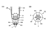
- 2 is a diagram for explaining a mechanical configuration example of the position indicator 1, FIG. 2 (A) is a partial longitudinal sectional view thereof, and FIG. 2 (B) is an external view thereof.
- FIG. In this embodiment, the position indicator 1 is formed to have a bar-like stylus appearance.
- the position indicator 1 of this embodiment includes a rod-shaped housing 3. As shown in FIG. 2A, the housing 3 is configured by a hollow cylindrical insulating portion 31 made of an insulating material such as synthetic resin. In this embodiment, at least a portion of the outer surface of the insulator 31 of the housing 3 where the operator holds the position indicator 1 is covered with a conductor 32 made of, for example, metal.
- a printed wiring board 40 In the housing 3, as shown in FIG. 2A, a printed wiring board 40, a battery 5, and a writing pressure detection unit 9 are disposed.
- the conductor portion 32 covering the outer peripheral surface of the housing 3 is electrically connected to the ground conductor of the printed wiring board 40, although not shown.
- a signal transmission control circuit 41 constituting an example of a control means, a wireless communication module 42, a side switch 43 including a push button switch,
- ID memory 44 that stores identification information (ID) of the position indicator 1
- oscillators 45 and 46 that output oscillation signals having different frequencies f1 and f2
- wiring patterns such as conductive patterns 47a to 47e, etc.
- a power switch 48 and a light emitting diode (LED) 49 are arranged.
- the conductive patterns 47a to 47e are schematically shown as one conductor pattern for simplification of description, but a plurality of conductive patterns 47a to 47e may be provided as necessary. Of course, it may be composed of a conductor pattern.
- the battery 5 is a power supply source for the electronic circuits and electronic components configured on the printed wiring board 40.
- the writing pressure detection unit 9 is configured in this embodiment as a variable capacitor that exhibits a capacitance according to the writing pressure applied to the center electrode 7 constituting the core.
- the wireless communication module 42 constitutes an example of the communication unit (first communication unit) of the present invention.
- the wireless communication module 42 receives the signal from the transmission function unit as an example of the first transmission unit and the position detection system.
- the wireless communication module of the Bluetooth (registered trademark) standard of the short-range wireless communication standard is used.
- the wireless communication module 42 is connected to the signal transmission control circuit 41.
- the wireless communication module 42 is not limited to Bluetooth, and may be, for example, infrared communication, or a Wi-Fi (registered trademark) standard wireless communication module.
- the side switch 43, the ID memory 44, and the writing pressure detection unit 9 constitute additional information generating means.
- the side switch 43 supplies the on / off information to the signal transmission control circuit 41 as an example of additional information.
- the ID memory 44 outputs the stored identification information (ID: Identification) of the position indicator 1 to the signal transmission control circuit 41 as an example of additional information.
- ID Identification
- the variable capacitor constituted by the writing pressure detection unit 9 exhibits a change in capacitance according to the writing pressure value applied to the center electrode 7 constituting the core body, and the signal transmission control circuit 41 has its capacitance. Is used to generate pen pressure information as an example of additional information.
- the oscillators 45 and 46 generate an AC signal for forming a position detection signal transmitted from the position indicator 1 of this embodiment, and supply the generated AC signal to the signal transmission control circuit 41.
- the oscillator 45 generates an AC signal having a frequency f1
- the oscillator 46 generates an AC signal having a frequency f2 different from the frequency f1.
- the signal transmission control circuit 41 generates different position detection signals based on the oscillator 45 and the oscillator 46. That is, the signal transmission control circuit 41, in combination with the oscillator 45 and the oscillator 46, constitutes a means for generating a position detection signal, and constitutes two transmission units. Then, the signal transmission control circuit 41 uses one of the two generated position detection signals as a position detection signal transmitted from the position indicator 1.
- a plurality of transmission units for generating and transmitting position detection signals for each of a plurality of types of position indicators of the active type described later are provided, and a signal transmission control circuit You may comprise so that selection control may be carried out by 41.
- the battery 5 is configured to be housed in the housing 3 as shown in FIGS. 1 and 2A, and the signal transmission control circuit 41 on the printed wiring board 40 is configured.
- the power supply voltage of the electronic circuit unit such as is generated by the battery 5.
- a terminal 52 is a terminal that is electrically connected to the power supply circuit portion on the printed wiring board 40.
- the positive electrode 51 of the battery 5 is in contact with and electrically connected to the terminal 52.
- the negative electrode of the battery 5 is directly connected to the ground conductor of the printed wiring board 40 or connected to the ground conductor of the printed wiring board 40 via the conductor portion 32 of the housing 3. It is made to press-contact with the terminal which is elastically displaced.
- the operator 48a of the power switch 48 disposed on the printed wiring board 40 is provided so as to be operable from the outside through an opening provided in the housing 3, as shown in FIG. Yes.
- the user can turn the power switch 48 on and off by sliding the operation member 48a.
- On the printed wiring board 40 there is also formed a power supply circuit section that generates a power supply voltage from the voltage from the battery 5 when the power switch 48 is turned on.
- one end side in the center line direction of the hollow cylindrical insulator portion 31 constituting the housing 3 is a tapered portion 33 that gradually tapers.
- a peripheral electrode 6 made of, for example, an annular conductive metal is attached to the outer peripheral side of the tapered portion 33.
- the peripheral electrode 6 and the conductor part 32 on the outer peripheral surface of the housing 3 are insulated by interposing an insulator part 31 therebetween.
- the peripheral electrode 6 is electrostatically coupled to the position detection system 2 to form a signal receiving unit from the position detection system in this embodiment.
- the peripheral electrode 6 is electrically connected to the conductor pattern 47 a of the printed wiring board 40 by a lead conductor member 61 that penetrates the insulator portion 31.
- the conductor pattern 47a is connected to the input end of the signal transmission control circuit 41.
- the central electrode 7 made of a conductive rod-like body is disposed so that one end side protrudes outside from the hollow portion of the tapered portion 33 of the housing 3.
- the center electrode 7 serves as a core constituting the pen tip of the pen-shaped position indicator 1.
- the center electrode 7 constitutes an example of a second transmission unit for transmitting a position detection signal.
- the end opposite to the side projecting to the outside is a printed wiring.
- the conductive pattern 47b formed on the substrate 40 is electrically connected.
- the conductive pattern 47 b is connected to the output end of the signal transmission control circuit 41.
- the position indicator 1 also operates as a passive type position indicator that does not transmit a position detection signal.
- the center electrode 7 is connected to the conductor of the position detection system 2. This serves to suck up the electric charge through the electrostatic coupling portion.
- the peripheral electrode 6 is provided around the central electrode 7.
- the combination of the peripheral electrode 6 and the center electrode 7 is for the improved position indicator of the passive method described above.
- a shield member 8 for effectively preventing mutual electrical interference is provided between the peripheral electrode 6 and the center electrode 7.
- the shield member 8 of this embodiment is provided so as to surround the center electrode 7, whereby the shield member 8 is interposed between the peripheral electrode 6 and the center electrode 7, so that the peripheral electrode 6 and the center electrode 7 The coupling capacity between them is made as small as possible.
- the center electrode 7 and the peripheral electrode 6 also constitute a communication unit (second communication unit).
- the center electrode 7 constitutes a transmission unit (second transmission unit)
- the peripheral electrode 6 constitutes a receiver (second receiver)
- the center electrode 7 constitutes a receiver (second receiver)
- the peripheral electrode 6 constitutes a transmitter (second transmitter). You may make it comprise.
- the center electrode 7 serving as the core body is fitted with a pen pressure detection unit 9 disposed in the hollow portion of the housing 3 at the end opposite to the side protruding outward.
- the indicator 1 is locked in the hollow portion of the housing 3.
- the center electrode 7 is configured to be detached from the writing pressure detection unit 9 by being pulled out. That is, the center electrode 7 as the core body can be exchanged for the position indicator 1.
- the writing pressure detection unit 9 is a variable capacitor (see, for example, Japanese Patent Application Laid-Open No. 2011-186803) exhibiting a capacitance according to the pressure (writing pressure) applied to the center electrode 7 as a core. It is configured.
- the electrodes at both ends of the variable capacitor constituted by the writing pressure detection unit 9 are connected to the signal transmission control circuit 41 by the conductive pattern 47c.
- the signal transmission control circuit 41 sets the position indicator 1 of this embodiment to any of a plurality of configuration types (modes). And determining whether to transmit the position detection signal through the center electrode 7 based on the determination control, and further controlling the transmission of the additional information through the center electrode 7 or the wireless communication module 42. Do.
- the position detection system 2 used together with the position indicator 1 there are a plurality of configuration types such as a passive system, an improved passive system, and an active system as described above.
- the position detection system 2 includes a wireless communication module that can communicate with the wireless communication module 42 of the position indicator 1, a pen that indicates a configuration type in which the position detection system 2 can be operated by the wireless communication module.
- the seed information is transmitted to the position indicator 1.
- the position indicator 1 receives the pen type information from the position detection system by the reception function of the wireless communication module 42 (an example of the reception function of the communication unit), and any configuration based on the received pen type information. It is determined whether or not the position indicator should be of the type (mode), and initialization is performed so that the position indicator of the determined configuration type is obtained.
- the position indicator 1 receives a signal from the position detection system through the peripheral electrode 6.
- receiving an example of the reception function of the communication unit
- the device 1 discriminates these differences and determines which configuration type position indicator should be used based on the discrimination result. In this case, when the configuration type information is not obtained from the position detection system through the wireless communication module 42, it is possible to determine which configuration type (mode) of the position indicator should be used.
- the signal transmission control circuit 41 of the position indicator 1 is a configuration type (mode) of the position indicator 1 based on the information received from the position detection system 2 through the wireless communication module 42 or the signal received through the peripheral electrode 6.
- the position indicator 1 is synchronized with a signal received from the position detection system through the wireless communication module 42 or the peripheral electrode 6 in the initial configuration type (mode). A process of controlling to send a detection signal and additional information is also performed.
- the position indicator 1 performs initial setting based on information received from the position detection system 2 through the wireless communication module 42, and synchronizes based on a signal received from the position detection system 2 through the wireless communication module 42.
- the above initial setting and the above synchronization processing will be described with reference to the timing chart of FIG.
- the position indicator 1 completes the pairing of the so-called position indicator 1 and the position detection system 2 in a state where the communication connection with the position detection system 2 is established via the wireless communication module 42.
- the signal Sp for communication connection with the position detection system 2 and pairing is intermittently transmitted through the wireless communication module 42 at a constant period To, through the position detection system 2. To send to.
- the position detection system 2 When the position detection system 2 confirms the reception of the signal Sp for pairing from the position indicator 1, the position detection system 2 determines that the pairing with the position indicator 1 is possible. Then, the information on the configuration type of the position indicator operating with the position detection system is sent.
- the position indicator 1 When the position indicator 1 confirms the reception of the configuration type information from the position detection system (see FIG. 3A) through the wireless communication module 42, the position indicator 1 can be paired with the position detection system 2.
- the initial setting is performed using the received information on the configuration type. That is, in this example, the configuration type information is an example of information for initial setting in the position indicator 1.
- This initial setting includes, for example, the frequency of the signal transmitted from the position indicator 1, selection of the signal transmitted from the position indicator 1 (selection of position detection signal and additional information), and the signal transmitted from the position indicator 1.
- Setting of transmission timing (for example, one data transmission for each external synchronization signal or a case where there is no external synchronization signal and transmission is continued at a specified interval) is included.
- the position detection system 2 when the position indicator 1 transmits a pairing signal Sp and the position detection system 2 receives the signal Sp, the position detection system 2 sends the configuration type information to the position indicator. 1 and the position indicator 1 performs initial setting based on the information of the configuration type.
- the position detection system 2 may transmit the signal Sp for pairing to the position indicator 1 through the wireless communication module intermittently at a constant period To.
- the signal Sp for pairing includes information on the configuration type of the position indicator that operates with the position detection system 2.
- the position indicator 1 when the position indicator 1 receives the signal Sp from the position detection system through the wireless communication module 42, the position indicator 1 performs initial setting using information on the configuration type included in the signal Sp. When the initial setting is completed, the position indicator 1 receives the signal Sp for pairing and transmits a response indicating that pairing is completed to the position detection system 2.
- the position indicator 1 When pairing is performed as described above and the initial setting in the position indicator 1 is completed, the position indicator 1 starts transmission of a position detection signal and additional information to the position detection system according to the initial setting. Prepare. Further, when the position detection system 2 recognizes that the pairing with the position indicator 1 is possible, the position detection system 2 stops the transmission of the signal Sp through the wireless communication module. A reference signal (external synchronization signal) with respect to the transmission timing of the signal from the position indicator 1 is transmitted through the wireless communication module.
- the transmission of the position detection signal and the additional information from the position indicator 1 to the position detection system 2 is performed in synchronization with the signal (external synchronization signal) received from the position detection system by the wireless communication module 42. Thereby, in a position detection system, it becomes possible to receive the signal from the position indicator 1 reliably and correctly.
- the position indicator 1 sends all of the position detection signal and the additional information to the position detection system 2 through the center electrode 7 (or the peripheral electrode 6).
- the position detection signal and the writing pressure information of the additional information are sent to the position detection system 2 through the center electrode 7 (or the peripheral electrode 6), and the identification information.
- the ID is a case where the ID is transmitted to the position detection system 2 through the wireless communication module 42.
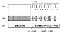
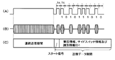
- the position detection system 2 transmits the external synchronization signal SYC through, for example, a predetermined cycle through the wireless communication module after pairing with the position indicator 1.
- the position indicator 1 receives the external synchronization signal SYC
- the position indicator 1 passes through the center electrode 7 (or the peripheral electrode 6) and receives a position detection signal (burst signal).
- the additional information is transmitted to the position detection system 2.
- all of the additional information is not transmitted to the position detection system 2 through the center electrode 7 (or the peripheral electrode 6), but at the timing based on the external synchronization signal SYC, the identification information ID, etc. Some or all of the additional information may be transmitted to the position detection system 2 through the wireless communication module 42.
- the position detection system 2 may receive the position detection signal and the additional information sent from the position indicator 1 at the timing synchronized with the external synchronization signal after the transmission of the external synchronization signal SYC.
- the signal from the device 1 can be obtained.
- the additional information need not always be sent together with the position detection signal, but may be sent at a predetermined interval.
- the oscillator of the position detection system and the oscillator of the timing signal generation circuit of the position indicator 1 operate at substantially the same frequency, but the timing shifts over time due to the difference in frequency. For this reason, the transmission interval of the external synchronization signal SYC from the position detection system 2 is set to be equal to or less than an interval that can be accommodated with a deviation that does not affect the operation.
- the first example and the second example described above are examples in which the position indicator 1 is configured such that the reception timing of the external synchronization signal SYC and the transmission timing of the position detection signal and additional information do not overlap.
- the configuration includes a timing signal generation circuit that generates a signal that is synchronized with the external synchronization signal SYC from the position detection system 2, so that the reception timing of the external synchronization signal SYC and the position detection are detected.
- the transmission timing of the service signal and additional information may overlap.
- the third example is an example in that case.
- a timing signal generation circuit that generates a signal synchronized with the external synchronization signal SYC from the position detection system 2 is provided.
- the transmission timing of the next position detection signal and additional information is set to a timing synchronized with the external synchronization signal SYC by the signal.
- the transfer rate of the position detection signal and the additional information can be increased. Also in the third example, the position detection system 3 does not need to transmit the external synchronization signal SYC in accordance with the transmission timing of the position detection signal from the position indicator 1 or the additional information, and sets the time interval. You may make it open and transmit.
- the position indicator 1 receives the external synchronization signal SYC from the position detection system 2 and detects the position at a timing synchronized with the received external synchronization signal SYC. An additional signal and additional information were sent. However, the position indicator 1 transmits a synchronization signal for notifying the timing for transmitting the position detection signal and the additional information to the position detection system 2, and the position detection system 2 receives the synchronization signal from the position indicator 1. You may make it receive the signal transmitted from the position indicator 1 based on a signal.
- the position detection system 2 has a wireless communication module and transmits setting information (for example, configuration type information) for initial setting in the position indicator 1 but does not perform synchronization.
- setting information for example, configuration type information
- the position detection system 2 has no wireless communication module and transmits setting information from the sensor to the position indicator 1.
- a signal received from the sensor of the position detection system 2 is received by the receiving unit including the center electrode 7 or the peripheral electrode 6 on the pen tip side of the position indicator 1, the initial setting is performed, and the position detection system 2 Start communication.
- the position detection system 2 does not have a wireless communication module and the setting information is not transmitted from the sensor.
- the position indicator 1 and the position detection system 2 cannot be paired, and the position indicator 1 is based on a default value set (stored) in the position indicator 1 in advance. Start sending signals.
- FIG. 4 is a block diagram showing the configuration of an electronic circuit formed on the printed wiring board 40 in the housing 3 of the position indicator 1 of this embodiment, mainly the detailed internal configuration of the signal transmission control circuit 41. It is a figure which shows an example.
- the signal transmission control circuit 41 includes a control unit 410 made of, for example, an IC (Integrated Circuit), a pen type determination unit 411, a center electrode transmission signal generation unit 412, and a wireless transmission signal generation unit 413. , Switch circuits 416, 417 for switching between a position detection signal selection switch circuit 414, a feedback signal generation circuit 415, a passive type position indicator, and a passive type improved type and active type position indicator. It is comprised including.
- IC Integrated Circuit
- the control unit 410 includes a setting unit 4101 for performing the above-described initial setting and a synchronization unit 4102 for transmitting a transmission signal synchronized with the external synchronization signal SYC from the position detection system 2 as functional units. Yes.
- the control unit 410 is connected to a variable capacitance capacitor configured by the writing pressure detection unit 9, and the control unit 410 determines the center of the capacitance of the variable capacitance capacitor configured by the writing pressure detection unit 9.
- the pressure (writing pressure value) applied to the electrode 7 is calculated.
- an on / off state signal of the side switch 43 is supplied to the control unit 410.
- the control unit 410 generates side switch information that is additional information regarding the side switch 43 from the on / off state signal of the side switch 43.
- the ID memory 44 is connected to the control unit 410, and the control unit 410 reads and acquires the identification information (ID) of the position indicator 1 from the ID memory 44 as necessary.
- the ID memory 44 may store the identification information stored in advance in the position indicator 1, or the identification information that is the storage content of the storage ID memory 44 is received through the wireless communication module 42, for example. Further, it may be configured such that it can be rewritten by a command from the position detection system 2.
- the setting unit 4101 of the control unit 410 determines each of a plurality of types of additional information, in this example, writing pressure information, side switch information, and identification information, according to information based on the pen type determination result from the pen type determination unit 411. The initial setting of whether to transmit from the center electrode 7 or to transmit wirelessly from the wireless communication module 42 is performed.
- control unit 410 supplies the additional information transmitted through the center electrode 7 to the center electrode transmission signal generation unit 412, and the additional information transmitted through the wireless communication module 42 is transmitted to the wireless transmission signal generation unit 413. Supply.
- the center electrode transmission signal generation unit 412 is connected to the center electrode 7, and as described later, additional information to be transmitted is transmitted to the position detection system 2 through the center electrode 7 together with the position detection signal.
- the wireless transmission signal generation unit 413 is connected to the transmission unit 421 of the wireless communication module 42, and additional information to be transmitted is wirelessly transmitted to the position detection system 2 through the transmission unit 421.
- the control unit 410 receives the external synchronization signal SYC from the position detection system 2 through the reception unit 422 of the wireless communication module 42, and the synchronization unit 4102 performs position detection based on the received external synchronization signal SYC. Control is performed so that the signal and the additional information are transmitted from the center electrode transmission signal generation unit 412 through the center electrode 7, or the additional information is transmitted from the wireless transmission signal generation unit 413 through the transmission unit 421 of the wireless communication module 42.
- the center electrode transmission signal generation unit 412 detects the position to which the AC signal of the frequency f1 from the oscillator 45 and the AC signal of the frequency f2 from the oscillator 46 are to be transmitted according to the switching selection by the control unit 410 of the switch circuit 414. And a feedback signal from the feedback signal generation circuit 415 is supplied as a position detection signal to be transmitted. In this example, the feedback signal generation circuit 415 amplifies the signal received from the position detection system 2 through the peripheral electrode 6 to enhance the signal and further invert the phase. A configuration example and a processing example of the feedback signal generation circuit 415 will be described in detail later.
- the control unit 410 generates a switching selection signal for the switch circuit 414 based on the initial setting information set based on the pen type determination result from the pen type determination unit 411.
- connection part between the center electrode transmission signal generation part 412 and the center electrode 7 is connected to the conductor part 32 of the housing 3 through the switch circuit 416.
- the peripheral electrode 6 is connected to the conductor portion 32 of the housing 3 through the switch circuit 417.
- the switch circuits 416 and 417 are switched by an on / off control signal from the control unit 410.
- the control unit 410 generates on / off control signals for the switch circuits 416 and 417 based on the initial setting information set based on the pen type determination result from the pen type determination unit 411.
- the pen type determination unit 411 includes a pen type table memory 4111 and a determination processing unit 4112. Information from the position detection system 2 received by the reception unit 422 of the wireless communication module 42 is supplied to the determination processing unit 4112 of the pen type determination unit 411, and a signal received from the position detection system 2 through the peripheral electrode 6 is received. Supplied.
- the pen type table memory 4111 a plurality of types of configuration types of the position indicator 1, and the presence / absence of transmission of a position detection signal and a position detection signal to be transmitted are generated in each type of position indicator.
- the pen type table information indicating whether the frequency of the oscillator and the additional information is transmitted from the center electrode 7 or transmitted through the wireless communication module 42 is stored.
- the pen type table information may be stored in advance in the pen type table memory 4111.
- the pen type table information is configured to be written and rewritten by a command from the position detection system 2 through the wireless communication module 42. ing.
- the determination processing unit 4112 determines the information received from the position detection system 2 received by the reception unit 422 of the wireless communication module 42 or the signal received from the sensor unit of the position detection system 2 through the peripheral electrode 6, and the pen type table. With reference to the pen type table information in the memory 4111, the configuration type of the position indicator suitable for the position detection system 2 to be used with the position indicator 1 is determined. Based on the determination result, the presence / absence of signal transmission from the center electrode 7, the information on the position detection signal transmitted from the center electrode 7 and the additional information, and additional information transmitted through the wireless communication module 42 are provided. Information about what is generated is generated, and the generated information is supplied to the control unit 410.
- the control unit 410 generates a switching selection signal for the switch circuit 414 and on / off control signals for the switch circuits 416 and 417 based on the initial settings set based on the information from the pen type determination unit 411, and In addition to being supplied to the switch circuits 414, 416, and 417, additional information to be supplied to the center electrode transmission signal generation unit 412 and additional information to be supplied to the wireless transmission signal generation unit 413 are determined and supplied.
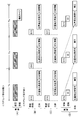
- FIG. 5 shows an example of pen type table information of the pen type determination unit 411.
- the example of FIG. 5 is table information on five types of position indicators of configuration type 1 to configuration type 5 (mode 1 to mode 5). After determining the configuration type (mode) of the position indicator, the pen type determination unit 411 generates control information to be supplied to the control unit 410 with reference to the pen type table information. Below, in the position indicator 1 of this embodiment, it demonstrates that each structure type (mode) is switched by control by the control part 410.
- FIG. 1 shows an example of pen type table information of the pen type determination unit 411.
- the example of FIG. 5 is table information on five types of position indicators of configuration type 1 to configuration type 5 (mode 1 to mode 5). After determining the configuration type (mode) of the position indicator, the pen type determination unit 411 generates control information to be supplied to the control unit 410 with reference to the pen type table information. Below, in the position indicator 1 of this embodiment, it demonstrates that each structure type (mode) is switched by control by the control part 410.
- Configuration type 1 (mode 1) is a passive position indicator, and no signal is transmitted from the center electrode 7, and all additional information is transmitted through the wireless communication module 42. That is, in the signal transmission control circuit 41 of the position indicator 1, when the pen type determination unit 411 determines this configuration type 1 (mode 1), the control unit 410 turns on the switch circuits 416 and 417, and the center electrode The transmission signal generation unit 412 is set to a non-operating state. The switch circuit 417 may be off. Then, the control unit 410 performs control so that all additional information is transmitted to the position detection system 2 through the transmission unit 421 of the wireless communication module 42 through the wireless transmission signal generation unit 413. The identification information may not need to be transmitted as additional information.
- Configuration type 2 (mode 2) is an improved passive position indicator.
- the control unit 410 turns off the switch circuits 416 and 417 based on the information from the pen type determination unit 411, and switches the switch circuit. 414 switches to a state in which the signal from the feedback signal generation circuit 415 is selected. All the additional information is controlled to be transmitted from the control unit 410 to the position detection system 2 through the wireless transmission signal generation unit 413 and the transmission unit 421 of the wireless communication module 42.
- the identification information may not need to be transmitted as additional information.
- Configuration type 3 (mode 3) is the first type of active position indicator.
- the control unit 410 determines that the configuration type is 3 (mode 3)
- the control unit 410 turns off the switch circuit 416 and turns on the switch circuit 417.
- the switch circuit 414 switches to a state of selecting an AC signal from the oscillator 45 having the frequency f1. All the additional information is controlled to be transmitted from the control unit 410 to the position detection system 2 through the wireless transmission signal generation unit 413 and the transmission unit 421 of the wireless communication module 42.
- the identification information may not need to be transmitted as additional information.
- Configuration type 4 (mode 4) is the second type of active position indicator. If the pen type determination unit 411 determines that the configuration type is 4 (mode 4), the control unit 410 turns off the switch circuit 416 and turns on the switch circuit 417 based on the information from the pen type determination unit 411. In this example, the switch circuit 414 switches to a state of selecting an AC signal from the oscillator 46 having the frequency f2. Of the additional information, the pen pressure information and the side switch information are transmitted together with the position detection signal from the center electrode 7, and the identification information ID is detected through the wireless transmission signal generation unit 413 and the transmission unit 421 of the wireless communication module 42. Control to transmit to system 2.
- Configuration type 5 (mode 5) is the second type of active position indicator.
- the control unit 410 turns off the switch circuit 416 and turns on the switch circuit 417.
- the switch circuit 414 switches to a state of selecting an AC signal from the oscillator 46 having the frequency f2. All of the additional information is controlled so as to be transmitted from the center electrode 7 together with the position detection signal.
- the signal transmission control circuit 41 determines the configuration type of the position indicator based on the information and signals received from the sensor unit of the position detection system 2 through the reception unit 422 and the peripheral electrode 6 of the wireless communication module 42.
- the position indicator 1 is determined to have the configuration of the determined configuration type position indicator.
- the position indicator 1 of this embodiment can automatically configure and use various types of position indicators corresponding to various types of position detection systems 2. That is, it is possible to input a position instruction to the plurality of position detection systems 2 of various methods only with the position indicator 1 of this embodiment. For this reason, it is not necessary to prepare a separate position indicator for each of the plurality of position detection systems 2 of various methods, which is very convenient and reduces the cost burden for the user. Become.
- the pen type information received from the position detection system 2 received through the wireless communication module 42 is not limited to the configuration type information that directly identifies each of the configuration types 1 to 5.
- the pen type table information may be information that indirectly indicates the number of each configuration type 1 to 5 or the address of each configuration type in the pen type table memory 4111.
- each processing function of the determination processing unit 4112, the center electrode transmission signal generation unit 412, and the wireless transmission signal generation unit 413 of the pen type determination unit 411 is configured by the control unit 410 as software processing function means. Is also possible. The same applies to the feedback signal generation circuit 415.
- the signal transmission control circuit 41 first determines whether or not information is received by the receiving unit 422 of the wireless communication module 42 (step S1). When it is determined that the information is received, whether or not the received information is pen type information. A determination is made (step S2). When it is determined in step S2 that the received information is pen type information, the signal transmission control circuit 41 determines the configuration type (pen type) of the position indicator based on the received pen type information, and the pen type. With reference to the table memory 4111, the signal transmitted from the center electrode 7 and the transmission unit 421 of the wireless communication module 42 is determined and initialized (step S3). As described above, this initial setting includes setting whether or not to transmit a position detection signal from the center electrode 7.
- step S3 the signal transmission control circuit 41 executes signal transmission based on the initial setting according to the configuration type determined in step S3 through the center electrode 7 and the transmission unit 421 of the wireless communication module 42 (step S3). S4).
- the signal transmission control circuit 41 determines whether or not the information from the position detection system 2 through the receiving unit 422 of the wireless communication module 42 cannot be received (step S5), and determines that the information cannot be received. Sometimes, the process returns to step S4 to continue signal transmission according to the determined configuration type.
- step S5 when it is determined that the information from the position detection system 2 through the receiving unit 422 of the wireless communication module 42 cannot be received, the signal transmission control circuit 41 determines whether or not a predetermined time has passed since the signal cannot be received. (Step S6). When it is determined in step S6 that the predetermined time or more has not elapsed, the signal transmission control circuit 41 returns the process to step S4 and continues signal transmission according to the determined configuration type.
- step S6 When it is determined in step S6 that the predetermined time or more has elapsed, the signal transmission control circuit 41 pauses signal transmission from the center electrode 7 and the transmission unit 421 of the wireless communication module 42, and puts the position indicator 1 in the sleep state. (Step S7). In this sleep state, in order to reduce power consumption by reducing the battery 5 as much as possible, the power to the reception unit 422 of the wireless communication module 42, the control unit 410 of the signal transmission control circuit 41, and the pen type determination unit 411 However, the unnecessary voltage supply to other parts is stopped.
- step S7 the signal transmission control circuit 41 returns the process to step S1, and repeats the processes after step S1 described above.
- step S1 When it is determined in step S1 that the receiving unit 422 of the wireless communication module 42 has not received information, or in step S2, when it is determined that the received information is not pen type information, the signal transmission control circuit 41 It is determined whether or not a signal is received through the peripheral electrode 6 (step S11 in FIG. 7). When it is determined in step S11 that no signal is received through the peripheral electrode 6, the signal transmission control circuit 41 turns on the switch circuit 416 and connects the center electrode 7 to the ground of the printed wiring board 40 through the conductor portion 32. A configuration type 1 state is established by connecting to a conductor (ground) (step S18). After step S18, the signal transmission control circuit 41 returns the process to step S1 in FIG. 6, and repeats the processes after step S1.
- step S12 When it is determined in step S11 that a signal has been received through the peripheral electrode 6, it is determined whether the pen type can be determined from the received signal (step S12). When it is determined in step S12 that the pen type cannot be determined, the signal transmission control circuit 41 turns on the switch circuit 416, and the center electrode 7 is connected to the ground conductor (ground) of the printed wiring board 40 through the conductor portion 32. ) To be in the configuration type 1 state (step S18). After step S18, the signal transmission control circuit 41 returns the process to step S1 in FIG. 6, and repeats the processes after step S1.
- the signal transmission control circuit 41 determines the configuration type (pen type) of the position indicator based on the received signal, and stores the pen type table 4111. Referring to the center electrode 7 and the signal to be transmitted from the transmitter 421 of the wireless communication module 42 is determined and initialized (step S13). As described above, this initial setting includes setting whether or not to transmit a position detection signal from the center electrode 7.
- the signal transmission control circuit 41 After step S13, the signal transmission control circuit 41 performs signal transmission based on the initial setting according to the configuration type determined in step S13 through the center electrode 7 and the transmission unit 421 of the wireless communication module 42 (step S13). S14).
- the signal transmission control circuit 41 determines whether or not the signal can be received through the peripheral electrode 6 (step S15). When it is determined that the signal cannot be received, the process returns to step S14. Continue signal transmission according to the determined configuration type.
- step S15 When it is determined in step S15 that the signal cannot be received through the peripheral electrode 6, the signal transmission control circuit 41 determines whether or not a predetermined time has elapsed since the signal could not be received (step S16). When it is determined in step S16 that the predetermined time or more has not elapsed, the signal transmission control circuit 41 returns the process to step S14 and continues signal transmission according to the determined configuration type.
- step S16 When it is determined in step S16 that the predetermined time or more has elapsed, the signal transmission control circuit 41 pauses signal transmission from the center electrode 7 and the transmission unit 421 of the wireless communication module 42, and puts the position indicator 1 in the sleep state. (Step S17). And after this step S17, the signal transmission control circuit 41 returns a process to step S1, and repeats the process after step S1 mentioned above.
- FIG. 8 is a diagram showing a circuit example of a main part of the position indicator 1A of configuration type 2, and in particular, a circuit configuration example of the feedback signal generation circuit 415 and a circuit configuration example of the power supply circuit unit 50 omitted above. It is shown.
- the power supply circuit unit 50 includes a DC / DC converter 501, generates a power supply voltage + Vcc from the voltage of the battery 5, and supplies it to the signal transmission control circuit 41 and others.
- a power switch 48 is provided between the DC / DC converter 501 and the battery 5.
- a series circuit of a resistor 502 and an LED 49 is connected between the output terminal of the DC / DC converter 501 and the ground conductor.
- the feedback signal generation circuit 415 is configured as a signal enhancement processing circuit in this example, and includes a sense amplifier 510, a signal amplification factor variable circuit 520, and a transformer 530.
- the sense amplifier 510 includes an operational amplifier 511 and a capacitor 512 connected between the inverting input terminal and the output terminal of the operational amplifier 511.
- An inverting input terminal of the operational amplifier 511 is connected to a connection terminal 513 connected to the peripheral electrode 6.
- the reference voltage Vref described above is supplied to the non-inverting input terminal of the operational amplifier 511.
- the peripheral electrode 6 of the position indicator 1A and the position detection system 2A are coupled via a capacitance C1.
- this alternating current signal is supplied to the connection terminal 513 as a current signal via the capacitance C1 and the peripheral electrode 6 and input to the sense amplifier 510. Is done.
- the capacitor 512 is for detecting a current signal input via the capacitance C1.
- the sense amplifier 510 inverts the phase of the AC signal input as a current signal through the connection terminal 513 and outputs the inverted signal to the signal amplification factor variable circuit 520.
- the signal amplification factor variable circuit 520 includes an operational amplifier 521 and a variable resistor 522 connected between the inverting input terminal and the output terminal of the operational amplifier 521.
- the amplification factor of the signal amplification factor variable circuit 520 is variably set, and as a result, the signal detection sensitivity of the position indicator 1A is controlled.
- the AC signal amplified by the signal amplification factor variable circuit 520 is supplied to the primary winding 530a of the transformer 530.
- the number of lines is set large (n1 ⁇ n2). Therefore, on the secondary winding 530b side of the transformer 530, the amplitude of the output signal of the signal amplification factor variable circuit 520 is multiplied according to the winding number ratio to obtain an AC signal (voltage signal) having a large amplitude. It is done.
- One end of the secondary winding 530b of the transformer 530 is connected to a connection terminal 523 connected to a core body 71 made of a rod-shaped conductor of the center electrode 7 shielded by the shield member 8, and the secondary winding 530b of the transformer 530 is connected. Is connected to the ground conductor of the printed wiring board 40. Therefore, the output signal converted to a large amplitude AC signal voltage by the feedback signal generation circuit 415 is supplied to the center electrode 7 through the connection terminal 523.
- the center electrode 7 of the position indicator 1A and the position detection system 2A are coupled via a capacitance. Then, an AC signal is fed back from the position indicator 1A to the position detection system 2A.
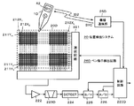
- the position detection system 2A in this example has a configuration of a mutual capacitance type position detection system in which a sensor electrode includes an input electrode and an output electrode, and a change in the coupling capacitance of a touch point touched by the position indicator 1A is detected. is there.
- the position detection system 2A of this example includes a sensor unit 20A, a transmission unit 21, a reception unit 22, a wireless communication unit 25, and a control unit 220A.
- the sensor unit 20A includes a plurality of linear conductors extending in the lateral direction (X-axis direction) of the sensor input surface, in this example, m transmission conductors 23Y 1 , 23Y 2 ,..., 23Y m (m is 1 or more). And a plurality of (in this example, n) receiving conductors 24X 1 , 24X 2 ,... Extending in the longitudinal direction (Y-axis direction) of the sensor input surface orthogonal to the transmitting conductors 23Y 1 to 23Y m.
- the plurality of transmission conductors 23Y 1 to 23Y m are arranged at equal intervals in the Y-axis direction and connected to the transmission unit 21.
- the plurality of receiving conductors 24X 1 to 24X n are arranged at equal intervals in the X-axis direction and are connected to the receiving unit 22.
- the plurality of transmission conductors 23Y and the plurality of reception conductors 24X are arranged at a predetermined interval, and have a plurality of intersections (cross points) with an orthogonal relationship. At each cross point, the transmission conductor 23Y and the reception conductor 24X can be regarded as being coupled via a predetermined capacitance.
- the transmission unit 21 supplies a predetermined AC signal to the transmission conductor 23Y based on the control of the control unit 220.
- the transmission unit 21 may supply the same AC signal to the plurality of transmission conductors 23Y 1 , 23Y 2 ,..., 23Y m while sequentially switching one by one, or a plurality of mutually different pluralities. May be simultaneously supplied to the plurality of transmission conductors 23Y 1 , 23Y 2 ,..., 23Y m .
- the plurality of transmission conductors 23Y 1 , 23Y 2 ,..., 23Y m may be divided into a plurality of groups, and different AC signals may be used for each group.
- the signal component transmitted is detected. If the coupling capacitance between the transmission conductor 23Y and the reception conductor 24X is equal at all cross points, when the position indicator 1 is not present on the sensor unit 20, all the reception conductors of the sensor unit 20 are used.
- 24X 1, 24X 2, ⁇ the received signal of a predetermined level is detected at the receiver 22 from the 24X n.
- the transmission conductor 23Y, the reception conductor 24X, and the position indicator 1A constituting the cross point of the contact position are coupled through capacitance. That is, the capacitance is changed by the position indicator 1A, and the reception signal level obtained from the reception conductor 24X of the cross point where the position indicator 1A exists is compared with the reception signal level of other cross points. Will change.
- the reception unit 22 detects the reception conductor 24X in which the level of the reception signal has changed among the plurality of reception conductors 24X 1 , 24X 2 ,..., 24X n , thereby indicating the position indicated by the position indicator 1A. Is detected. Then, the control unit of the position detection system 2 (not shown) detects the transmission conductor 23Y that supplies an AC signal from the transmission unit 21 and the reception conductor 24X in which the reception signal level has changed in the reception unit 22. Thus, the cross point where the position indicator 1A is in contact is detected.
- the position detection system 2 detects a cross point where the finger approaches or contacts based on the same principle. In that case, a part of the AC signal supplied to the transmission conductor 23Y flows to the ground through the finger and through the human body of the user. Therefore, the reception signal level of the reception conductor 24X constituting the cross point where the finger exists changes.
- the reception unit 22 detects the reception conductor 24X constituting the cross point where the finger exists by detecting the change in the reception signal level.
- the position detection system 2A can detect the indicated position in the sensor unit 20A in the same manner as the principle of finger position detection.
- the position detection system corresponding to the position indicator of the configuration type 1 uses a spread code as an AC signal to be transmitted to the position indicator and obtains a correlation between the transmission signal and the received signal, thereby indicating the position indicated by the position indicator. This is compensated for the decrease in detection sensitivity.
- the affinity between the position indicator 1A and the position detection system 2A is high without using a spreading code or the like.
- the versatility is high, and a predetermined waveform correlation is ensured between the input signal and the output signal, and position detection on the sensor unit 20A can be performed with high sensitivity.
- the AC signal supplied to the transmission conductor 23Y passes through the capacitance C1 as shown in FIG. Further, the current signal is input to the feedback signal generation circuit 415 through the connection terminal 513 through the peripheral electrode 6.
- the AC signal (current signal) input to the feedback signal generation circuit 415 is phase-inverted by the sense amplifier 510 and then amplified by the signal amplification factor variable circuit 520 and boosted (multiplied) by the transformer 530 to enhance the signal. Then, the voltage signal is supplied to the center electrode 7 through the connection terminal 523. That is, the AC signal input from the sensor unit 20A to the feedback signal generation circuit 415 via the peripheral electrode 6 is reversed in phase and converted to a large amplitude signal through the center electrode 7 in the feedback signal generation circuit 415. Returned to the sensor unit 20A.
- the AC signal fed back from the center electrode 7 of the position indicator 1A to the sensor unit 20A of the position detection system 2A is an enhanced signal having a phase opposite to that of the AC signal supplied to the transmission conductor 23Y.
- the position indicator 1A functions to further increase the change in the AC signal in the reception signal of the reception conductor 24X. For this reason, the position detection system 2A can detect the contact position of the position indicator 1A with high sensitivity.
- the detection operation is further stabilized by connecting the ground conductor of the position indicator 1A to the human body. That is, in this embodiment, the housing 3 of the position indicator 1 ⁇ / b> A is covered with the conductor portion 32 connected to the ground conductor of the printed wiring board 40. For this reason, the AC signal supplied to the transmission conductor 23Y in the position detection system 2A flows to the ground through the user's human body through the position indicator 1A, so that the signal detection operation can be further stabilized.
- the voltage at the transmission conductor 23Y of the sensor unit 20A of the position detection system 2A is V
- the voltage at the center electrode 7 of the position indicator 1A of this embodiment is e
- the voltage between the peripheral electrode 6 and the center electrode 7 is If the capacitance is C2 (see FIG. 1), e ⁇ C1 / C2 ⁇ V There is a relationship. For this reason, it is advantageous that the capacitance C2 between the peripheral electrode 6 and the center electrode 7 is as small as possible to increase the potential e of the center electrode 7.
- the shield member 8 is interposed between the peripheral electrode 6 and the center electrode 7 so that the coupling between the two is made as small as possible. Therefore, in the position indicator 1 of this embodiment, by interposing the shield member 8, the capacitance C2 between the peripheral electrode 6 and the center electrode 7 is reduced, the voltage e can be increased, and the efficiency The sensitivity can be increased well.
- the position indicator 1A of the above-described embodiment is configured to receive the AC signal from the position detection system 2A at the peripheral electrode 6 and feed back the output AC signal whose signal is enhanced from the center electrode 7 to the position detection system 2A.
- an electrode for receiving an AC signal from the position detection system 2A may be used as the center electrode 7 and an electrode for returning the signal-enhanced AC signal to the position detection system 2 may be used as the peripheral electrode 6.
- writing pressure information, side switch information, and identification information are wirelessly transmitted from the wireless communication module 42 to the wireless communication unit 25 of the position detection system 2A.
- the pen pressure information, the side switch information, and the identification information received by the wireless communication unit 25 are supplied to the control circuit 220A and transmitted to the host computer, for example, together with the detected position information.
- the additional information from the position indicator of the configuration type 1 is transmitted from the wireless communication module 42 to the position detection system.
- FIG. 10 is a diagram illustrating a circuit example of a main part of the position indicator 1B of the configuration type 3 and the corresponding position detection system 2B.
- the configuration type 3 position indicator 1B transmits an AC signal having a frequency f1 as a position detection signal, and writing pressure information, side switch information, and identification information, which are additional information, are all transmitted from the wireless communication module 42 to the position detection system.
- the data is sent to the 2B wireless communication unit 25B.
- the position detection system 2B includes a sensor unit 20B, a pen instruction detection circuit 26B connected to the sensor unit 20B, and a wireless communication unit 25B. After the pairing with the position indicator 1B is completed from the wireless communication unit 25B of the position detection system 2B, the external synchronization signal SYC is transmitted to the position indicator 1B as described above.
- the sensor unit 20B is formed by laminating a first conductor group 211, an insulating layer (not shown), and a second conductor group 212 in order from the lower layer side.
- a first conductor group 211 a plurality of first conductors 211Y 1 , 211Y 2 ,..., 211Y m (m is an integer of 1 or more) extending in the lateral direction (X-axis direction) are separated from each other by a predetermined distance. And arranged in the Y-axis direction.
- the second conductor group 212 extends in a direction intersecting with the extending direction of the first conductors 211Y 1 , 211Y 2 ,..., 211Y m , in this example, the orthogonal vertical direction (Y-axis direction).
- the plurality of second conductors 212X 1 , 212X 2 ,..., 212X n (n is an integer equal to or greater than 1) are spaced apart from each other by a predetermined distance and arranged in parallel in the X-axis direction.
- first conductors 211Y 1 , 211Y 2 ,..., 211Y m the conductors are referred to as first conductors 211Y.
- second conductors 212X 1 , 212X 2 ,..., 212X n the conductors will be referred to as second conductors 212X.
- the pen instruction detection circuit 26B includes a selection circuit 221, an amplification circuit 222, a band-pass filter 223, a detection circuit 224, a sample hold circuit 225, and an AD (Analog to Digital) that serve as an input / output interface with the sensor unit 20B. ) It consists of a conversion circuit 226 and a control circuit 220B.
- the selection circuit 221 selects one conductor from each of the first conductor group 211Y and the second conductor group 212X based on the control signal from the control circuit 220B.
- the conductor selected by the selection circuit 221 is connected to the amplification circuit 222, and the signal from the position indicator 1B is detected by the selected conductor and amplified by the amplification circuit 222.
- the output of the amplifier circuit 222 is supplied to the band pass filter 223B, and only the component of the frequency f1 of the signal transmitted from the position indicator 1B is extracted.
- the output signal of the bandpass filter 223B is detected by the detection circuit 224.
- the output signal of the detection circuit 224 is supplied to the sample hold circuit 225, sampled and held at a predetermined timing by the sampling signal from the control circuit 220B, and then converted into a digital value by the AD conversion circuit 226.
- Digital data from the AD conversion circuit 226 is read and processed by the control circuit 220B.
- the control circuit 220B operates to send control signals to the sample and hold circuit 225, the AD conversion circuit 226, and the selection circuit 221, respectively, according to a program stored in the internal ROM. Further, the control circuit 220B calculates the position coordinates on the sensor unit 20B instructed by the position indicator 1B from the digital data from the AD conversion circuit 226.
- FIG. 11 is a timing chart for explaining signals transmitted from the position indicator 1B of the configuration type 3 to the corresponding position detection system 2B.
- a signal based on the AC signal having the frequency f1 is continuously sent from the position indicator 1B of the configuration type 3 through the center electrode 7 as a position detection signal.
- the position indicator 1 of this embodiment can transmit an AC signal having the frequency f1 and an AC signal having the frequency f2 as position detection signals.
- the frequency of the position detection signal can be switched when noise having the same frequency as the position detection signal exists.
- the position detection signal includes a continuous transmission period having a predetermined period length Ta and a pause period having a predetermined period length Tb. Is one cycle and the one cycle is repeated.
- the pause period of the predetermined period length Tb is used as a window section for detecting the presence or absence of noise. It is detected whether noise having the same frequency as the signal for use exists. When it is detected that noise having the same frequency as that of the position detection signal is present in the window section, the control circuit 220B of the position detection system 2B notifies the position indicator 1B through the wireless communication unit 25B. .
- the reception unit 422 of the wireless communication module 42 of the position indicator 1B transfers the notification to the control unit 410 of the signal transmission control circuit 41.
- the control unit 410 of the signal transmission control circuit 41 switches and controls the switch circuit 414 to switch from the oscillator 45 having the frequency f1 to the oscillator 46 having the frequency f2.
- the position detection system 2B In response to the notification, the control unit 410 switches and controls the switch circuit 414 to switch from the oscillator 46 having the frequency f2 to the oscillator 45 having the frequency f1.
- the control circuit 220B of the position detection system 2B detects the noise NR in the window section shown in FIG. 11B, and notifies the position indicator 1B through the wireless communication unit 25B. send.
- the control unit 410 receives the notification from the position detection system 2B through the reception unit 422 of the wireless communication module 42, and the frequency of the position detection signal is as shown in FIG.
- the switch circuit 414 is controlled to be switched from the frequency f1 to the frequency f2. Therefore, even if noise having the same frequency as the frequency of the position detection signal is present in the vicinity of the position detection system 2B, the influence of the noise is not affected by switching the frequency of the position detection signal. it can.
- the bandpass filter 223B has a pass frequency band having the frequency f1 as a center frequency so that both the frequency f1 and the position detection signal of the frequency f2 can be handled. And a state in which the frequency f2 is set as the pass frequency band having the center frequency as a center frequency.
- the control circuit 220B controls which pass frequency band is used.
- FIG. 12 is a diagram illustrating a circuit example of a main part of the position indicator 1C of the configuration type 4 and the corresponding position detection system 2C.
- the configuration type 4 position indicator 1C transmits an AC signal having a frequency f2 as a position detection signal, and writing pressure information and side switch information, which are examples of additional information important as a position indicator, are a position detection signal.
- the signal is sent to the position detection system 2C through the center electrode 7.
- the position indicator 1C sends the identification information of the additional information from the wireless communication module 42 to the wireless communication unit 25C of the position detection system 2C.
- the position detection system 2C includes a sensor unit 20C, a pen instruction detection circuit 26C connected to the sensor unit 20C, and a wireless communication unit 25C. After the pairing with the position indicator 1C is completed from the wireless communication unit 25C of the position detection system 2C, the external synchronization signal SYC is transmitted to the position indicator 1C as described above.
- the sensor unit 20C has the same configuration as the sensor unit 20B of the position detection system 2B.
- the pen instruction detection circuit 26C has the same configuration as the pen instruction detection circuit 26B except for the band-pass filter 223C and the control circuit 220C.
- the band pass filter 223C of the position indicator 1C of the configuration type 4 has a pass frequency band having the frequency f2 as a center frequency.
- the control circuit 220C has a function of detecting pen pressure information and side switch information transmitted together with the position detection signal.
- the center electrode transmission signal generation unit 412 receives a control from the control unit 410 and repeats a signal having a pattern with a continuous transmission period and a transmission data period as one cycle. Make output.
- FIG. 13A shows an example of a control signal supplied to the center electrode transmission signal generation unit 412 from the control unit 410 of the position indicator 1C.
- the center electrode transmission signal generation unit 412 continuously transmits an oscillation signal having a frequency f2 as a burst signal as shown in FIG. 13B during a fixed period in which the high level of the control signal in FIG. 13A is maintained. (Continuous transmission period in FIG. 13C).
- the length of this continuous transmission period is a time length in which the pointing position on the sensor unit 20C by the position pointing device 1C can be detected by the pen pointing detection circuit 26C of the position detection system 2C.
- the first conductor The time length is such that all of 211Y and the second conductor 212X can be scanned once or more, preferably more than once.
- the control unit 410 of the position indicator 1C calculates the writing pressure applied to the center electrode 7 based on the capacitance of the variable capacitor of the writing pressure detection unit 9, and calculates the writing pressure.
- the writing pressure value information is obtained as a multi-bit value (binary code).
- the control unit 410 generates the on / off information of the side switch 43 as side switch information as 1-bit or multiple-bit information.
- the control unit 410 controls the control signal to a high level or a low level at a predetermined cycle (Td) in the transmission data period after the end of the continuous transmission period
- the AC signal of frequency f2 is ASK (Amplitude ⁇ Shift Keying) modulated. Instead of ASK modulation, an OOK (On Off Keying) signal may be used.
- This start signal is a timing signal for enabling the subsequent data transmission timing to be accurately determined by the pen instruction detection circuit 26C of the position detection system 2C.
- a burst signal in a continuous transmission period can be used as a timing signal.
- the center electrode transmission signal generation unit 412 of the position indicator 1C receives the control from the above control unit 410, and in the transmission data period, following the start signal, a plurality of bits of pen pressure information and one or a plurality of bits of side Switch information is sent sequentially.
- the control signal (FIG. 13A) is set to the low level and the AC signal is not transmitted.
- the transmission data (binary code) is “1”
- the control signal is set to a high level and control is performed so that an AC signal is transmitted, so that ASK modulation is performed.
- the control circuit 220C detects the indication position by the position indicator 1C from the reception signal in the continuous transmission period in the same manner as the position detection system 2B described above. Then, the control circuit 220C waits for the end of the continuous transmission period, and when detecting the start signal after the end of the continuous transmission period, detects the writing pressure information and the data of the side switch information in the transmission data period and restores them. Perform the action. Then, the control circuit 220C outputs the detection information of the indicated position by the position indicator 1C, the writing pressure information, and the side switch information together with the identification information received through the wireless communication unit 25C to a host computer or the like.
- the position indicator 1C of the configuration type 4 may also be configured to switch the frequency of the position detection signal in the same manner as the position indicator 1B of the configuration type 3 so that the influence of noise can be reduced.
- the band pass filter 223C and the control circuit 220C of the position detection system 2C are also configured to have the same functions as the band pass filter 223B and the control circuit 220B of the position detection system 2B corresponding to the configuration type 3.
- FIG. 14 is a diagram illustrating a circuit example of a main part of the position indicator 1D of configuration type 5 and the corresponding position detection system 2D.
- the position indicator 1D of the configuration type 5 sends an AC signal having a frequency f2 as a position detection signal, and all additional information, in this example, pen pressure information, side switch information, and identification information ID1, is a position detection signal. At the same time, the signal is sent to the position detection system 2D through the center electrode 7.
- the position detection system 2D includes a sensor unit 20D, a pen instruction detection circuit 26D connected to the sensor unit 20D, and a wireless communication unit 25D. After the pairing with the position indicator 1D is completed from the wireless communication unit 25D of the position detection system 2D, the external synchronization signal SYC is transmitted to the position indicator 1D as described above.
- the sensor unit 20D has the same configuration as the sensor unit 20B of the position detection system 2B.
- the pen instruction detection circuit 26D has the same configuration as the pen instruction detection circuit 26C, including the bandpass filter 223D, except for the control circuit 220D. That is, in this example, the band pass filter 223D has a pass frequency band having the frequency f2 as a center frequency.
- the control circuit 220D has a function of detecting pen pressure information, side switch information, and identification information ID1 sent together with the position detection signal.
- the center electrode transmission signal generation unit 412 receives the control from the control unit 410, and FIG. As shown in FIG. 5, a signal having a pattern in which the continuous transmission period and the transmission data period are one cycle is repeatedly output.
- FIG. 15A shows an example of a control signal supplied from the control unit 410 of the position indicator 1D to the center electrode transmission signal generation unit 412.
- the center electrode transmission signal generation unit 412 of the position indicator 1D in this example is controlled by the control signal in FIG. 15A, and in the continuous transmission period, as shown in FIG.
- the oscillation signal is continuously transmitted as a burst signal, and in the transmission data period, as shown in FIGS. 15B and 15C, writing pressure information, side switch information, and identification information ID1 are used as ASK signals. It transmits to the position detection system 2D through the center electrode 7.
- the control circuit 220D of the position detection system 2D detects the position on the sensor unit 20D instructed by the position indicator 1D based on the burst signal in the continuous transmission period, and also writes the pen pressure information and the side switch in the transmission data period. Information and identification information ID1 are detected and restored.
- the position indicator 1D transmits the identification information ID2 from the wireless communication module 42 to the position detection system 2D.
- the control circuit 220D compares the identification information ID2 acquired through the wireless communication unit 25D with the identification information ID1 received and detected through the center electrode 7, and the signal acquired from the position indicator 1D only when the two match. Is treated as valid.
- control circuit 220D validates the signal acquired from the position indicator 1D, the detection information of the indicated position by the position indicator 1D, the writing pressure information, the side switch information, and the identification information ID1, the host computer, etc. Output to.
- the plurality of configuration types of the position indicator described above are merely examples, and it goes without saying that the configuration types are not limited to those connected here.
- a signal is transmitted only from the center electrode 7, but the tilt angle and the rotation angle of the position indicator on the position detection system can be detected.
- the peripheral electrode 6 is divided into a plurality of parts, and a signal for sending out the peripheral divided electrodes from each of the divided peripheral divided electrodes is transmitted.
- the position indicator may be one configuration type.
- FIG. 16 shows a configuration example of the electromagnetic coupling type position indicator 100 according to the present invention, and corresponds to the conceptual configuration diagram of FIG. 1 showing the position indicator 1 of the embodiment described above.
- a position indicator 100 of this embodiment includes a signal transmission control circuit 141, a wireless communication module 142, a side switch 143, and a cylindrical housing 103 made of an insulating material such as resin. And an ID memory 144 and an oscillator 145, and a writing pressure detection unit 109.
- a battery 105 is provided in the housing 103 as a supply source of power supply voltage to the signal transmission control circuit 141, the wireless communication module 142, the side switch 143, the ID memory 144, the oscillator 145, and the like.
- the signal transmission control circuit 141 includes a pen type determination unit 1411.
- the writing pressure detection unit 109 is coupled with a core body 107 penetrating the ferrite core 110.
- the writing pressure detection unit 109 converts the writing pressure applied to the core body 107 into the writing pressure detection unit 109. It is detected as the capacitance of a variable capacitor composed of A coil 111 is wound around the ferrite core 110, and both ends of the coil 111 are connected to the signal transmission control circuit 141. Further, between the both ends of the coil 111, a capacitor 112 that constitutes a resonance circuit with the coil 111 is connected.
- the signal transmission control circuit 141 is connected to the wireless communication module 142, the side switch 143, the ID memory 144, and the oscillator 145, as in the position indicator 1 of the above-described embodiment, and a writing pressure detection unit.
- a variable capacitance capacitor 109 is also connected to the signal transmission control circuit 141.
- the signal transmission control circuit 141 selects and controls a signal to be transmitted through a resonance circuit including the coil 111 and the capacitor 112, and adds writing pressure information, side switch information, identification information, and the like. Whether to transmit information from the wireless communication module 142 or as a signal from the resonance circuit is selected and controlled.
- the resonance circuit constitutes the second transmission unit
- the transmission function unit of the wireless communication module 142 constitutes the first transmission unit.
- the reception function unit of the wireless communication module 142 constitutes a reception unit that receives pen type information from the position detection system.
- the pen type information received from the position detection system by the reception function unit of the wireless communication module 142 is supplied to the pen type determination unit 1411 of the signal transmission control circuit 141.
- the pen type determination unit 1411 can also be configured by a pen type determination processing unit and a pen type table memory.
- the signal transmission control circuit 141 of the position indicator 100 of this embodiment receives the pen type information from the position detection system, determines the pen type by the pen type determination unit 1411, determines the pen type, for example, FIG. ), (B), and (C), the three types of configuration types 6, 7, and 8 can be configured as position indicators 100A, 100B, and 100C.
- the signal transmission control circuit 141 causes the signal transmission control circuit 141 to display as shown in FIG. A position indicator 100A is configured. That is, in this configuration type 6, a variable capacitor composed of the pen pressure detection unit 109 is connected in parallel to a parallel resonance circuit composed of the coil 111 and the capacitor 112. Further, the side switch 143 and the capacitor 113 A series circuit is connected.
- the sensor unit of the position detection system 200A that is used together with the position indicator 100A of the configuration type 6 and sends the configuration type 6 to the position indicator 100A as pen type information is not illustrated, but a plurality of loop coils are provided.
- the loop coils are arranged in the X direction and the Y direction orthogonal to each other, and a transmission signal (AC signal) having a frequency fa is transmitted from the loop coil to the position indicator 100A.
- the AC signal from the position detection system 200A is received by the resonance circuit by electromagnetic coupling, and then the AC signal is fed back from the resonance circuit to the position detection system 200A.
- the position indicated by the position indicator 100A is detected from the position of the loop coil that has transmitted the AC signal and the position of the loop coil that has received the feedback signal from the position indicator 100A. .
- the feedback signal from the position indicator 100A changes when the resonance frequency of the resonance circuit changes according to the value of the capacitance of the variable capacitor formed by the writing pressure detection unit 109.
- the pen pressure information is detected by the change in frequency (or change in phase).
- the resonance frequency of the resonance circuit changes according to the turning on / off of the side switch 143.
- side switch information corresponding to ON / OFF of the side switch 143 is detected by a change in the frequency (or change in phase) of the feedback signal from the position indicator 100A.
- the identification information is transmitted to the wireless communication unit of the position detection system 200A through the transmission function unit of the wireless communication module 142.
- the signal transmission control circuit 141 causes the pen type information to be as shown in FIG.
- the position indicator 100B is configured. That is, in the configuration type 7, the parallel resonance circuit is composed of the coil 111 and the capacitor 112.
- the writing pressure information, the side switch information, and the identification information are all transmitted to the wireless communication unit of the position detection system 200B through the transmission function unit of the wireless communication module 142.
- the sensor unit of the position detection system 200B that is used together with the position indicator 100B of the configuration type 7 and sends the configuration type 7 to the position indicator 100B as the pen type information has the same configuration as the sensor unit of the position detection system 200A.
- a transmission signal (AC signal) having a frequency fa is transmitted from the coil to the position indicator 100B.
- an AC signal from the position detection system 200B is received by a resonance circuit by electromagnetic coupling, and then the AC signal is fed back from the resonance circuit to the position detection system 200B.
- the position detection system 200B detects the position indicated by the position indicator 100B in the same manner as the position detection system 200A.
- This configuration type 7 position detection system 200B does not have a function of monitoring the frequency and phase change of the feedback signal to detect additional information. Then, the position detection system 200B decodes the additional information received through the wireless communication unit so as to acquire writing pressure information, side switch information, and identification information.
- the signal transmission control circuit 141 causes the pen type information to be as shown in FIG. A position indicator 100C is configured. That is, in this configuration type 8 position indicator 100C, the parallel resonant circuit composed of the coil 111 and the capacitor 112 is coupled to the oscillator 145 to form an oscillation circuit 145S. The oscillation signal from the oscillation circuit 145S is transmitted to the position detection system 200C through a parallel resonance circuit including the coil 111 and the capacitor 112.
- the pen pressure information, the side switch information, and the identification information are all transmitted to the wireless communication unit of the position detection system 200C through the transmission function unit of the wireless communication module 142.
- the sensor unit of the position detection system 200C that is used together with the position indicator 100C of the configuration type 8 and sends the configuration type 8 to the position indicator 100C as pen type information is not illustrated, but a plurality of loop coils are provided. They are arranged in the X and Y directions orthogonal to each other.
- the position detection system 200C receives the AC signal transmitted from the position indicator 100C by a loop coil by electromagnetic coupling. Then, the position detection system 200C detects the position instructed by the position indicator 100C from the positions of the loop coils in the X direction and the Y direction that have received the AC signal.
- the above configuration types 6 to 8 are also examples, and there are various other types of configuration types for the electromagnetic coupling type position indicator and the position detection system, and the position indicator of the present invention includes those various types. Needless to say, it can also be configured to correspond to the configuration type.
- the identification information is not transmitted through the resonance circuit.
- the resonance operation of the resonance circuit or the oscillation operation of the oscillation circuit 145S It can also be set as the structure type which transmits identification information from the core 107 side as an ASK modulation signal or an OOK signal.
- FIG. 18 is a diagram showing a main part of a configuration type position indicator 1E having the functions of both an electrostatic coupling type active electrostatic pen and an electromagnetic coupling type electronic pen.
- FIG. 18B is a diagram when the position indicator 1E is viewed from the front end side of the center electrode 7 in the axial direction thereof. is there.
- FIG. 19 is a block diagram showing a configuration example of the electronic circuit unit of the position indicator 1E of this example.
- the peripheral electrode made of a conductor provided around the opening of the housing 3 in which the central electrode 7 is inserted is divided into six divided peripheral electrodes 6A, 6B, 6C, 6D, 6E. , 6F. As shown in FIGS. 18A and 18B, these peripheral division electrodes 6A to 6F are provided to be electrically insulated and separated from each other.
- the center electrode 7 is fitted to the writing pressure detection unit 9 through a through hole provided in the ferrite core 110, and can receive a signal from a signal transmission control circuit configured on the substrate 40. It is configured.
- a coil 111 is wound around the ferrite core 110, and a capacitor 112 is connected in parallel to the coil 111 via a switch circuit 114 as shown in FIG.
- the switch circuit 114 is turned off by the control signal from the control unit 410, and the parallel resonance circuit including the coil 111 and the capacitor 112 is not configured. .
- a signal from the signal transmission control circuit is transmitted through the center electrode 7, and the peripheral divided electrodes 6A to 6F are used as shield electrodes. .
- the switch circuit 114 is turned on by a control signal from the control unit 410, and a parallel resonance circuit including the coil 111 and the capacitor 112 is configured.
- the parallel resonance circuit receives a signal from the position detection system 2 by an electromagnetic coupling method and sends it back to send the position detection signal to the position detection system 2.
- the peripheral divided electrodes 6A to 6F are divided, the magnetic flux for electromagnetic coupling between the parallel resonance circuit and the position detection system 2 can be prevented from being shielded.
- the dielectric is sandwiched between the first electrode and the second electrode, and one of the first electrode and the second electrode is arranged in accordance with the writing pressure.
- a variable capacitor whose electrostatic capacitance is variable according to the writing pressure by making it movable in the center direction is used, it is not limited to this configuration.
- the writing pressure detection unit 9 may be configured using a semiconductor element whose capacitance is variable according to writing pressure as disclosed in Japanese Patent Application Laid-Open No. 2013-161307. Further, the writing pressure detection unit may be configured by using a structure or an element that makes an inductance value or a resistance value variable according to writing pressure instead of capacitance.
- the additional information is not limited to writing pressure information, side switch information, identification information, and the like, and other various information such as battery remaining amount information can be used as additional information. .
- the driving power source of the position indicator is a battery.
- a capacitor that accumulates the power source voltage may be provided in the position indicator, and the capacitor may be used as the driving power source.
- the configuration for accumulating the power supply voltage in the capacitor may be a configuration of a charging circuit that receives and charges power energy from the outside by electromagnetic induction or electric field coupling, or a dedicated charging terminal is provided on the position indicator.
- the charging current may be supplied from the charging device through the charging terminal.
- external power energy electromagtic energy or electric field energy
- the position indicator has two transmitters, ie, the central electrode and the wireless communication module, but may be provided with three or more transmitters.
- the position indicator automatically becomes a configuration type corresponding to the position detection system by, for example, bringing the position indicator closer to the sensor unit of the position detection system. I did it. However, it is not a position detection system, but communicates with an external device such as a personal computer that can communicate with the wireless communication module of the position indicator, and by selecting a configuration type with the external device such as a personal computer, the position indicator You may comprise so that it can set to the selected desired structure type.
- a configuration type switch setting switch is provided in the position indicator, and the position indicator can be set to the desired configuration type by a switching operation using the switch setting switch.
- a push button switch 146 that can be operated by the user is provided in the housing 103, and a push operation signal of the push button switch 146 is supplied to the signal transmission control circuit 141.
- the signal transmission control circuit 141 performs control so that the configuration type is changed each time the push button switch 146 is pressed by the user, for example.
- a push button switch may be provided as well.
Landscapes
- Engineering & Computer Science (AREA)
- General Engineering & Computer Science (AREA)
- Theoretical Computer Science (AREA)
- Physics & Mathematics (AREA)
- Human Computer Interaction (AREA)
- General Physics & Mathematics (AREA)
- Electromagnetism (AREA)
- Computer Networks & Wireless Communication (AREA)
- Signal Processing (AREA)
- Power Engineering (AREA)
- Position Input By Displaying (AREA)
- Arrangements For Transmission Of Measured Signals (AREA)
- Transceivers (AREA)
Abstract
Description
外部装置との通信を行う通信部と、
前記通信部で受信した前記外部装置からの信号に基づいて初期設定を行う設定手段と、
位置検出用信号を発生する手段と、
前記設定手段で行われた初期設定と、前記外部装置から受信する信号とに基づいて、少なくとも前記位置検出用信号を送出するようにする制御手段と、
を備えることを特徴とする位置指示器を提供する。 In order to solve the above problems, the present invention provides:
A communication unit for communicating with an external device;
Setting means for performing an initial setting based on a signal from the external device received by the communication unit;
Means for generating a position detection signal;
Control means for sending at least the position detection signal based on the initial setting made by the setting means and a signal received from the external device;
A position indicator is provided.
この実施形態の位置指示器1は、棒状の筐体3を備える。この筐体3は、図2(A)に示すように、絶縁材料例えば合成樹脂からなる中空の円筒状形状の絶縁体部31により構成されている。そして、この実施形態では、筐体3の絶縁体部31の外表周面の少なくとも操作者が当該位置指示器1を把持する部分は、例えば金属からなる導電体部32で覆われている。 [Description of Mechanical Configuration Example of Position Indicator of Embodiment]
The
この実施形態においては、位置指示器1と共に使用される位置検出システム2としては、前述したようにパッシブ方式、パッシブ方式の改良方式、アクティブ方式など、複数の構成タイプのものが存在する。この実施形態では、位置検出システム2は、位置指示器1の無線通信モジュール42と通信可能な無線通信モジュールを備える場合、当該無線通信モジュールにより、位置検出システム2が動作可能な構成タイプを示すペン種情報を、位置指示器1に送信するようにする。位置指示器1は、無線通信モジュール42の受信機能(通信部の受信機能の例)により、当該位置検出システムからのペン種情報を受信し、当該受信したペン種情報に基づいて、いずれの構成タイプ(モード)の位置指示器とすべきかを決定し、その決定した構成タイプの位置指示器の構成となるように初期設定する。 [Initial setting of
In this embodiment, as the
・ペン先から送信する送信信号の周波数を決定する、
・ペン先から送信する連続信号の周期を決定する、
・筆圧情報、サイドスチッチ情報、識別情報IDをペン先又は無線通信モジュール42のどちらから送信するかを決定する、
などを行って、それぞれの決定に応じた設定を実行して初期設定する。 That is, in the
・ Determine the frequency of the transmission signal transmitted from the pen tip.
・ Determine the period of the continuous signal transmitted from the pen tip.
-Decide whether to send pen pressure information, side stitch information, or identification information ID from the pen tip or the
Etc., and execute the setting according to each determination to initialize.
以上のようにして、位置指示器1と位置検出システム2とのペアリングが成立した後の、位置指示器1と位置検出システム2との同期の仕方の幾つかの例について、図3(B),(C),(D)に基づいて説明をする。なお、図3(B)及び(C)の例は、位置指示器1は、位置検出用信号及び付加情報の全てを、中心電極7(あるいは周辺電極6)を通じて、位置検出システム2に送出する場合であり、図3(D)の例は、位置検出用信号と付加情報の内の筆圧情報は、中心電極7(あるいは周辺電極6)を通じて、位置検出システム2に送出すると共に、識別情報IDは、無線通信モジュール42を通じて位置検出システム2に送出するようにする場合である。 <Example of how to synchronize>
As described above, some examples of how the
この第1の例においては、位置検出システム2は、位置指示器1とのペアリングの後、無線通信モジュールを通じて外部同期信号SYCを、例えば所定の周期で送信する。位置指示器1は、図3(B)に示すように、この外部同期信号SYCを受信すると、その受信に基づいて、中心電極7(あるいは周辺電極6)を通じて、位置検出用信号(バースト信号)及び付加情報を位置検出システム2に送信する。 <First example>
In the first example, the
この第2の例は、第1の例と同様に、位置指示器1は、位置検出システム2からの外部同期信号SYCに基づいて、中心電極7(あるいは周辺電極6)を通じて、位置検出用信号(バースト信号)及び付加情報を位置検出システム2に送信する。しかし、この第2の例では、位置検出システム2からの外部同期信号SYCに同期する信号を発生するタイミング信号発生回路を備える。そのため、位置検出システム2は、位置指示器1が位置検出用信号及び付加情報を送信するタイミング毎に、外部同期信号SYCを送信する必要はなく、図3(C)に示すように、所定の時間間隔で、外部同期信号SYCを送信するようにすることができる。 <Second example>
In the second example, as in the first example, the
上述の第1の例及び第2の例は、位置指示器1では、外部同期信号SYCの受信タイミングと、位置検出用信号や付加情報の送信タイミングとが重ならないようにした例であった。しかし、第2の例と同様に、位置検出システム2からの外部同期信号SYCに同期する信号を発生するタイミング信号発生回路を備える構成とすることで、外部同期信号SYCの受信タイミングと、位置検出用信号や付加情報の送信タイミングとが重なってもよい。第3の例は、その場合の例である。 <Third example>
The first example and the second example described above are examples in which the
図4は、この実施形態の位置指示器1の筐体3内のプリント配線基板40上に形成されている電子回路の構成を示すブロック図であり、主として、信号送信制御回路41の内部詳細構成例を示す図である。 [Description of Configuration Example of Internal Electronic Circuit of
FIG. 4 is a block diagram showing the configuration of an electronic circuit formed on the printed
次に、電源スイッチ48がオンとされた後における信号送信制御回路41が実行する処理動作例を、図6及び図7のフローチャートを参照しながら説明する。 [Example of processing operation in signal transmission control circuit 41]
Next, an example of processing operation performed by the signal
<構成タイプ2の位置指示器1Aと、対応する位置検出システム2A>
図8は、構成タイプ2の位置指示器1Aの主要部の回路例を示す図であり、特に、帰還信号生成回路415の回路構成例と、上記では省略した電源回路部50の回路構成例を示したものである。 [Description of operation of various types of position indicators and corresponding position detection systems]
<
FIG. 8 is a diagram showing a circuit example of a main part of the
e≦C1/C2・V
なる関係がある。このため、周辺電極6と中心電極7との間の静電容量C2は、できるだけ小さい方が、中心電極7の電位eを高くするのに有利である。 The voltage at the
e ≦ C1 / C2 ・ V
There is a relationship. For this reason, it is advantageous that the capacitance C2 between the peripheral electrode 6 and the
図10は、構成タイプ3の位置指示器1Bと、対応する位置検出システム2Bとの主要部の回路例を示す図である。構成タイプ3の位置指示器1Bは、位置検出用信号として周波数f1の交流信号を送出すると共に、付加情報である筆圧情報、サイドスイッチ情報及び識別情報は、全て無線通信モジュール42から位置検出システム2Bの無線通信部25Bに送出する。 <
FIG. 10 is a diagram illustrating a circuit example of a main part of the position indicator 1B of the
図12は、構成タイプ4の位置指示器1Cと、対応する位置検出システム2Cとの主要部の回路例を示す図である。構成タイプ4の位置指示器1Cは、位置検出用信号として周波数f2の交流信号を送出すると共に、位置指示器として重要な付加情報の例である筆圧情報及びサイドスイッチ情報は、位置検出用信号と共に、中心電極7を通じて位置検出システム2Cに送出する。そして、位置指示器1Cは、付加情報の識別情報は、無線通信モジュール42から位置検出システム2Cの無線通信部25Cに送出する。 <Structure Type 4
FIG. 12 is a diagram illustrating a circuit example of a main part of the
図14は、構成タイプ5の位置指示器1Dと、対応する位置検出システム2Dとの主要部の回路例を示す図である。構成タイプ5の位置指示器1Dは、位置検出用信号として周波数f2の交流信号を送出すると共に、全ての付加情報、この例では筆圧情報、サイドスイッチ情報及び識別情報ID1は、位置検出用信号と共に、中心電極7を通じて位置検出システム2Dに送出する。 <
FIG. 14 is a diagram illustrating a circuit example of a main part of the
<静電結合方式の他の例>
上述した位置指示器の複数の構成タイプは、一例であって、ここに接続した構成タイプのものに限られるものではないことは言うまでもない。例えば、上述のアクティブ方式の位置指示器においては、中心電極7のみから信号を送出するようにしたが、位置指示器の位置検出システム上での傾き角や回転角を検出することができるようにするために、周辺電極6を、複数個に分割して、その分割した複数個の周辺分割電極のそれぞれから、それらの周辺分割電極を識別することができるようにするための信号を送出する構成の位置指示器を、一つの構成タイプとしてもよい。 [Other Embodiments]
<Other examples of electrostatic coupling method>
The plurality of configuration types of the position indicator described above are merely examples, and it goes without saying that the configuration types are not limited to those connected here. For example, in the above-described active type position indicator, a signal is transmitted only from the
また、上述の実施形態は、静電結合方式の位置指示器及び位置検出システムの場合であったが、電磁結合方式の位置指示器及び位置検出システムの場合にも、この発明は適用可能である。 <Example of electromagnetic coupling method>
Moreover, although the above-mentioned embodiment was the case of the position indicator and position detection system of an electrostatic coupling system, this invention is applicable also in the case of the position indicator and position detection system of an electromagnetic coupling system. .
図18は、静電結合方式のアクティブ静電ペン及び電磁結合方式の電子ペンの両方の機能を備える構成タイプの位置指示器1Eの要部を示す図で、図18(A)は、導電性の中心電極7側の構成部分を説明するための図であり、図18(B)は、当該位置指示器1Eを、中心電極7の先端側から、その軸心方向に見たときの図である。また、図19は、この例の位置指示器1Eの電子回路部の構成例を示すブロック図である。 <Example of hybrid position indicator of both electrostatic coupling type and electromagnetic coupling type>
FIG. 18 is a diagram showing a main part of a configuration
上述の実施形態の筆圧検出ユニット9,109は、誘電体を第1の電極と第2の電極で挟み、その第1の電極と第2の電極の内、一方を筆圧に応じて軸心方向に移動可能にすることで、静電容量が筆圧に応じて可変となる可変容量コンデンサを用いるようにしたが、この構成に限られるものではない。例えば、特開2013-161307号公報に開示されているような筆圧に応じて静電容量を可変とする半導体素子を用いて筆圧検出ユニット9を構成することもできる。また、静電容量ではなく、インダクタンス値や抵抗値を筆圧に応じて可変とする構造や素子を用いることで、筆圧検出ユニットを構成するようにしてもよい。 [Other Embodiments or Modifications]
In the writing
DESCRIPTION OF
Claims (18)
- 外部装置との通信を行う通信部と、
前記通信部で受信した前記外部装置からの信号に基づいて初期設定を行う設定手段と、
位置検出用信号を発生する手段と、
前記設定手段で行われた初期設定と、前記外部装置から前記通信部を通じて受信する信号とに基づいて、少なくとも前記位置検出用信号の送出を制御する制御手段と、
を備えることを特徴とする位置指示器。 A communication unit for communicating with an external device;
Setting means for performing an initial setting based on a signal from the external device received by the communication unit;
Means for generating a position detection signal;
Control means for controlling transmission of at least the position detection signal based on an initial setting made by the setting means and a signal received from the external device through the communication unit;
A position indicator characterized by comprising. - 複数の構成タイプに切り替え設定可能であって、前記初期設定には、前記構成タイプの設定に関する処理を含む
ことを特徴とする請求項1に記載の位置指示器。 The position indicator according to claim 1, wherein the setting can be switched to a plurality of configuration types, and the initial setting includes processing related to the configuration type setting. - 前記通信部の送信機能部を第1の送信部として、前記第1の送信部とは異なる第2の送信部を備えると共に、互いに種類の異なる付加情報をそれぞれ発生する複数個の付加情報発生手段を備え、
前記制御手段は、前記設定手段により設定された前記構成タイプに応じて、前記第2の送信部を通じた前記位置検出用信号の送出を制御すると共に、前記複数個の付加情報発生手段からの前記付加情報の前記第1の送信部または前記第2の送信部からの送出を制御することで、前記選択された構成タイプに切り替え設定する
ことを特徴とする請求項2に記載の位置指示器。 The transmission function unit of the communication unit is a first transmission unit, and includes a second transmission unit different from the first transmission unit, and a plurality of additional information generation means for generating different types of additional information, respectively. With
The control unit controls transmission of the position detection signal through the second transmission unit according to the configuration type set by the setting unit, and the plurality of additional information generation units from the plurality of additional information generation units. The position indicator according to claim 2, wherein switching is set to the selected configuration type by controlling transmission of additional information from the first transmission unit or the second transmission unit. - 前記外部装置から前記通信部を通じて受信する信号には、前記位置検出用信号の送出のタイミングの基準となる同期信号を含む
ことを特徴とする請求項1に記載の位置指示器。 2. The position indicator according to claim 1, wherein a signal received from the external device through the communication unit includes a synchronization signal that is a reference of a timing of transmitting the position detection signal. - 前記第2の送信部は、細長の筒状の筐体の軸心方向の一方の端部に配置された導電性の部材を含み、
前記制御手段は、前記初期設定に基づいて、前記位置検出用信号を送出すると決定したときには、前記位置検出用信号を、前記第2の送信部の前記導電性の部材を通じて送出する
ことを特徴とする請求項3に記載の位置指示器。 The second transmission unit includes a conductive member disposed at one end in the axial direction of an elongated cylindrical casing,
When it is determined that the position detection signal is to be transmitted based on the initial setting, the control means transmits the position detection signal through the conductive member of the second transmission unit. The position indicator according to claim 3. - 前記一方の端部に配置された導電性の部材は、前記筐体の軸心方向の一方の端部に設けられた開口部から突出する電極芯または前記電極芯の周辺に配置された電極である
ことを特徴とする請求項5に記載の位置指示器。 The conductive member disposed at the one end is an electrode core projecting from an opening provided at one end in the axial direction of the casing or an electrode disposed around the electrode core. The position indicator according to claim 5, wherein the position indicator is provided. - 前記位置検出用信号を発生する手段は、複数個の発信部からなり、
前記制御手段は、前記初期設定に基づいて、前記複数個の発信部のいずれを位置検出用信号として送出するかを決定する
ことを特徴とする請求項1に記載の位置指示器。 The means for generating the position detection signal comprises a plurality of transmitters,
The position indicator according to claim 1, wherein the control unit determines which of the plurality of transmitters is to be transmitted as a position detection signal based on the initial setting. - 細長の筒状の筐体の軸心方向の一方の端部に印加される圧力を検出する圧力検出手段を備え、
前記付加情報は、前記圧力検出手段で検出された前記圧力の情報を含む
ことを特徴とする請求項3に記載の位置指示器。 Pressure detecting means for detecting a pressure applied to one end of the elongated cylindrical casing in the axial direction;
The position indicator according to claim 3, wherein the additional information includes information on the pressure detected by the pressure detection means. - 識別情報を記憶する記憶部を備え、
前記付加情報は、前記記憶部に記憶されている前記識別情報を含む
ことを特徴とする請求項3に記載の位置指示器。 A storage unit for storing identification information;
The position indicator according to claim 3, wherein the additional information includes the identification information stored in the storage unit. - 使用者の操作を受け付けるスイッチ手段を備え、
前記付加情報は、前記スイッチ手段によるスイッチ入力情報を含む
ことを特徴とする請求項3に記載の位置指示器。 Provided with switch means for accepting user operations,
The position indicator according to claim 3, wherein the additional information includes switch input information by the switch means. - 前記外部装置は、位置検出システムであって、
前記第2の送信部からの信号の前記位置検出システムへの送信は、前記第2の送信部と前記位置検出システムとの静電結合を通じて行われ、前記通信部の送信機能部で構成される第1の送信部からの信号の前記位置検出システムへの送信は、無線通信により行われる
ことを特徴とする請求項3に記載の位置指示器。 The external device is a position detection system,
Transmission of the signal from the second transmission unit to the position detection system is performed through electrostatic coupling between the second transmission unit and the position detection system, and is configured by a transmission function unit of the communication unit. The position indicator according to claim 3, wherein transmission of a signal from the first transmission unit to the position detection system is performed by wireless communication. - 前記外部装置は、位置検出システムであって、
前記第2の送信部は、前記位置検出システムからの信号を受信電極で受信した受信信号を信号処理し、送信電極を通じて前記位置検出システムに送出して帰還させる構成を含む
ことを特徴とする請求項5に記載の位置指示器。 The external device is a position detection system,
The second transmission unit includes a configuration in which a signal received from the position detection system is received by a reception electrode, signal processing is performed, and the signal is sent back to the position detection system through the transmission electrode to be fed back. Item 6. The position indicator according to Item 5. - 前記第2の送信部の前記受信電極及び前記送信電極は、細長の筒状の筐体の軸心方向の一方の端部に配置され、前記筒状の筐体の中心線上に配置された中心電極と、前記中心電極の周囲を囲む周辺電極とで構成される
ことを特徴とする請求項12に記載の位置指示器。 The reception electrode and the transmission electrode of the second transmission unit are disposed at one end in the axial direction of the elongated cylindrical casing, and are disposed on the center line of the cylindrical casing. The position indicator according to claim 12, comprising an electrode and a peripheral electrode surrounding the periphery of the center electrode. - 前記外部装置は、位置検出システムであって、
前記第2の送信部からの信号の前記位置検出システムへの送信は、前記第2の送信部と前記位置検出システムとの電磁結合を通じて行われ、前記通信部の送信機能部で構成される第1の送信部からの信号の前記位置検出システムへの送信は、無線通信により行われる
ことを特徴とする請求項3に記載の位置指示器。 The external device is a position detection system,
Transmission of the signal from the second transmission unit to the position detection system is performed through electromagnetic coupling between the second transmission unit and the position detection system, and is configured by a transmission function unit of the communication unit. The position indicator according to claim 3, wherein transmission of a signal from one transmission unit to the position detection system is performed by wireless communication. - 前記第2の送信部は、細長の筒状の筐体の軸心方向の一方の端部に配置され、前記筒状の筐体の中心線上に配置された中心電極と、前記中心電極の周囲を囲む複数個の周辺電極とで構成される
ことを特徴とする請求項3に記載の位置指示器。 The second transmitter is disposed at one end in the axial direction of an elongated cylindrical casing, and a center electrode disposed on a center line of the cylindrical casing, and a periphery of the central electrode The position indicator according to claim 3, comprising a plurality of peripheral electrodes surrounding the electrode. - 前記外部装置は、位置検出システムであって、
前記通信部で前記位置検出システムからの信号を受信しないときには、前記設定手段は、前記第2の送信部からは前記位置検出用信号は送信しない構成タイプであると初期設定する
ことを特徴とする請求項5に記載の位置指示器。 The external device is a position detection system,
When the communication unit does not receive a signal from the position detection system, the setting means initially sets the configuration type as not to transmit the position detection signal from the second transmission unit. The position indicator according to claim 5. - 前記外部装置は、位置検出システムであって、
前記構成タイプを特定するための情報に対応する、前記設定手段による前記第1の送信部及び前記第2の送信部から送出する信号の制御に関する設定情報が、テーブル情報として記憶されている記憶部を備える
ことを特徴とする請求項3に記載の位置指示器。 The external device is a position detection system,
A storage unit that stores, as table information, setting information relating to control of signals transmitted from the first transmission unit and the second transmission unit by the setting unit, corresponding to information for specifying the configuration type The position indicator according to claim 3, further comprising: - 前記通信部は、第1の通信部と第2の通信部とを含み、前記初期設定を行うための信号を第1の通信部で受信し、少なくとも前記位置検出用信号の送出を制御するための信号を第2の通信部で受信する
ことを特徴とする請求項1に記載の位置指示器。 The communication unit includes a first communication unit and a second communication unit, the first communication unit receives a signal for performing the initial setting, and controls at least transmission of the position detection signal. The position indicator according to claim 1, wherein the signal is received by the second communication unit.
Priority Applications (20)
| Application Number | Priority Date | Filing Date | Title |
|---|---|---|---|
| KR1020227013013A KR102487046B1 (en) | 2015-01-19 | 2015-01-19 | Pointing device |
| KR1020237042179A KR102649925B1 (en) | 2015-01-19 | 2015-01-19 | Pointing device |
| EP15878700.2A EP3249503A4 (en) | 2015-01-19 | 2015-01-19 | Pointing device |
| JP2015511134A JP5762659B1 (en) | 2015-01-19 | 2015-01-19 | Position indicator |
| PCT/JP2015/051229 WO2016117004A1 (en) | 2015-01-19 | 2015-01-19 | Pointing device |
| EP24158137.0A EP4345586A3 (en) | 2015-01-19 | 2015-01-19 | Position indicator |
| KR1020237000611A KR102521459B1 (en) | 2015-01-19 | 2015-01-19 | Pointing device |
| KR1020247008937A KR20240039226A (en) | 2015-01-19 | 2015-01-19 | Pointing device |
| KR1020177018244A KR102243548B1 (en) | 2015-01-19 | 2015-01-19 | Pointing device |
| KR1020237012167A KR102612427B1 (en) | 2015-01-19 | 2015-01-19 | Pointing device |
| KR1020217011437A KR102389701B1 (en) | 2015-01-19 | 2015-01-19 | Pointing device |
| EP19197752.9A EP3611605B1 (en) | 2015-01-19 | 2015-01-19 | Position indicator |
| CN202110270038.0A CN113031791B (en) | 2015-01-19 | 2015-01-19 | Position indicator |
| CN201580069384.5A CN107111399B (en) | 2015-01-19 | 2015-01-19 | Position indicator |
| TW108129237A TWI727398B (en) | 2015-01-19 | 2016-01-08 | Position indicator |
| TW105100557A TWI673630B (en) | 2015-01-19 | 2016-01-08 | Position indicator |
| US15/626,911 US10627927B2 (en) | 2015-01-19 | 2017-06-19 | Position indicator |
| US16/736,457 US11086420B2 (en) | 2015-01-19 | 2020-01-07 | Position indicator |
| US17/368,292 US11620008B2 (en) | 2015-01-19 | 2021-07-06 | Position indicator |
| US18/175,822 US20230205333A1 (en) | 2015-01-19 | 2023-02-28 | Position indicator |
Applications Claiming Priority (1)
| Application Number | Priority Date | Filing Date | Title |
|---|---|---|---|
| PCT/JP2015/051229 WO2016117004A1 (en) | 2015-01-19 | 2015-01-19 | Pointing device |
Related Child Applications (1)
| Application Number | Title | Priority Date | Filing Date |
|---|---|---|---|
| US15/626,911 Continuation US10627927B2 (en) | 2015-01-19 | 2017-06-19 | Position indicator |
Publications (1)
| Publication Number | Publication Date |
|---|---|
| WO2016117004A1 true WO2016117004A1 (en) | 2016-07-28 |
Family
ID=53887781
Family Applications (1)
| Application Number | Title | Priority Date | Filing Date |
|---|---|---|---|
| PCT/JP2015/051229 WO2016117004A1 (en) | 2015-01-19 | 2015-01-19 | Pointing device |
Country Status (7)
| Country | Link |
|---|---|
| US (4) | US10627927B2 (en) |
| EP (3) | EP3611605B1 (en) |
| JP (1) | JP5762659B1 (en) |
| KR (7) | KR102243548B1 (en) |
| CN (2) | CN113031791B (en) |
| TW (2) | TWI673630B (en) |
| WO (1) | WO2016117004A1 (en) |
Cited By (4)
| Publication number | Priority date | Publication date | Assignee | Title |
|---|---|---|---|---|
| WO2018074098A1 (en) * | 2016-10-18 | 2018-04-26 | 株式会社ワコム | Pairing method, position detection system, pointing device, and position detection device |
| WO2019106747A1 (en) * | 2017-11-29 | 2019-06-06 | 株式会社ワコム | Communication method executed between active pen and sensor controller, and active pen |
| WO2022224466A1 (en) * | 2021-04-19 | 2022-10-27 | 株式会社ワコム | Active pen, position detection system, and integrated circuit |
| US12141391B2 (en) | 2016-10-18 | 2024-11-12 | Wacom Co., Ltd. | Pairing method, position detecting system, position indicator and position detecting apparatus |
Families Citing this family (44)
| Publication number | Priority date | Publication date | Assignee | Title |
|---|---|---|---|---|
| CN104571732B (en) * | 2013-10-14 | 2018-09-21 | 深圳市汇顶科技股份有限公司 | Touch terminal, active stylus detection method and system |
| CN112328103B (en) | 2014-01-22 | 2024-07-23 | 株式会社和冠 | Signal processing method |
| KR102389698B1 (en) * | 2014-11-17 | 2022-04-22 | 가부시키가이샤 와코무 | Position indicator |
| EP3299936B1 (en) * | 2015-05-21 | 2020-01-01 | Wacom Co., Ltd. | Active stylus |
| JP6487782B2 (en) * | 2015-06-08 | 2019-03-20 | 株式会社ワコム | Setting method of configuration type in position indicator |
| EP3316110A4 (en) * | 2015-06-23 | 2018-06-20 | Ricoh Company, Ltd. | Communication terminal, management system, communication system, display method and program |
| KR102496591B1 (en) | 2015-08-19 | 2023-02-07 | 가부시키가이샤 와코무 | How a stylus detects a sensor controller, stylus, and sensor controller |
| JP6532105B2 (en) | 2015-12-17 | 2019-06-19 | 株式会社ワコム | Touch panel, signal processing apparatus and ground coupling method |
| US10579169B2 (en) | 2016-03-08 | 2020-03-03 | Egalax_Empia Technology Inc. | Stylus and touch control apparatus for detecting tilt angle of stylus and control method thereof |
| CN107390897B (en) * | 2016-03-08 | 2020-07-03 | 禾瑞亚科技股份有限公司 | Touch control device for detecting inclination angle and axial direction of pen body and control method thereof |
| CN105607766B (en) * | 2016-03-15 | 2017-12-22 | 深圳市华鼎星科技有限公司 | A kind of adjustable capacitance pressure transducer and true person's handwriting stylus |
| KR102523154B1 (en) * | 2016-04-22 | 2023-04-21 | 삼성전자주식회사 | Display apparatus, input device and control method thereof |
| CN105867711B (en) * | 2016-04-28 | 2019-04-09 | 深圳市华鼎星科技有限公司 | A kind of true person's handwriting stylus and touch device |
| JP6216909B1 (en) | 2016-06-28 | 2017-10-18 | 株式会社ワコム | Serial communication method and sensor controller |
| EP3477440A4 (en) * | 2016-06-28 | 2020-01-29 | Wacom Co., Ltd. | Serial communication method and sensor controller |
| JP6282790B1 (en) * | 2016-08-12 | 2018-02-21 | 株式会社ワコム | Stylus and sensor controller |
| TWI599919B (en) * | 2016-10-28 | 2017-09-21 | 翰碩電子股份有限公司 | Capacitive stylus with two transmit electrodes |
| KR102460472B1 (en) * | 2016-12-30 | 2022-11-01 | 엘지디스플레이 주식회사 | Touch sensing system, display device, active pen, and pen recognizing method |
| JP6908442B2 (en) * | 2017-06-06 | 2021-07-28 | 株式会社ワコム | Position indicator |
| US10585502B2 (en) * | 2017-08-17 | 2020-03-10 | Apple Inc. | Touch sensor excitation using transformer |
| TWI658381B (en) * | 2018-03-09 | 2019-05-01 | 宏碁股份有限公司 | Stylus and control method thereof |
| US10649550B2 (en) | 2018-06-26 | 2020-05-12 | Intel Corporation | Predictive detection of user intent for stylus use |
| KR102149389B1 (en) * | 2018-07-10 | 2020-08-28 | 삼성전기주식회사 | Camera module |
| WO2020023640A1 (en) | 2018-07-24 | 2020-01-30 | Shapirten Laboratories Llc | Power efficient stylus for an electronic device |
| KR102227274B1 (en) | 2018-08-09 | 2021-03-15 | 삼성전자주식회사 | Electronic pen device including a button, method for operation in the electronic pen device and system |
| CN109521893B (en) | 2018-10-17 | 2022-11-25 | 京东方科技集团股份有限公司 | Touch pen, touch panel, touch sensing system and control method thereof |
| CN112912826B (en) * | 2018-11-06 | 2024-07-23 | 三菱铅笔株式会社 | Stylus and method for manufacturing stylus |
| JP7155022B2 (en) | 2019-01-11 | 2022-10-18 | 株式会社ワコム | pen |
| KR20210017099A (en) * | 2019-08-06 | 2021-02-17 | 삼성전자주식회사 | Electronic device for recognizing stylus pen and method for operating thereof |
| JP7014757B2 (en) * | 2019-09-03 | 2022-02-01 | 株式会社ワコム | A method and touch controller performed by a device that derives the pen position and sends a report showing the derived pen position to the host computer. |
| WO2021084824A1 (en) | 2019-10-29 | 2021-05-06 | 株式会社ワコム | Electronic pen |
| EP4067109B1 (en) * | 2020-01-21 | 2024-05-01 | Wacom Co., Ltd. | Electronic pen, electronic pen cartridge, and electronic pen charging tray |
| US11449175B2 (en) | 2020-03-31 | 2022-09-20 | Apple Inc. | System and method for multi-frequency projection scan for input device detection |
| KR20210145876A (en) * | 2020-05-25 | 2021-12-03 | 삼성디스플레이 주식회사 | Electronic device |
| JP7482706B2 (en) * | 2020-07-08 | 2024-05-14 | 株式会社ワコム | Method performed by a stylus and sensor controller, stylus and sensor controller |
| US11997777B2 (en) | 2020-09-24 | 2024-05-28 | Apple Inc. | Electrostatic discharge robust design for input device |
| US11460933B2 (en) | 2020-09-24 | 2022-10-04 | Apple Inc. | Shield electrode for input device |
| US11287926B1 (en) * | 2020-09-25 | 2022-03-29 | Apple Inc. | System and machine learning method for detecting input device distance from touch sensitive surfaces |
| US11526240B1 (en) | 2020-09-25 | 2022-12-13 | Apple Inc. | Reducing sensitivity to leakage variation for passive stylus |
| JP7035160B2 (en) * | 2020-12-24 | 2022-03-14 | 株式会社ワコム | Systems including sensor controllers and styli, sensor controllers, and styli |
| KR20220119205A (en) | 2021-02-19 | 2022-08-29 | 삼성디스플레이 주식회사 | Electronic pen and interface device including the same |
| DE112021004860B4 (en) * | 2021-07-29 | 2024-06-06 | Wacom Co., Ltd. | METHOD FOR DETECTING A PIN SIGNAL, SENSOR CONTROL AND POSITION DETECTION SYSTEM |
| KR20230030715A (en) * | 2021-08-25 | 2023-03-07 | 삼성디스플레이 주식회사 | Input device and interface device including the same |
| KR20230129127A (en) * | 2022-02-28 | 2023-09-06 | 삼성디스플레이 주식회사 | Pen analog front end and pen communication method using the same |
Citations (3)
| Publication number | Priority date | Publication date | Assignee | Title |
|---|---|---|---|---|
| JPH09134246A (en) * | 1995-11-10 | 1997-05-20 | Seiko Denshi Kiki Kk | Coordinate indicator or device used with coordinate reader |
| JP2012022543A (en) * | 2010-07-15 | 2012-02-02 | Panasonic Corp | Touch panel system |
| JP2012221304A (en) * | 2011-04-11 | 2012-11-12 | Wacom Co Ltd | Position indicator |
Family Cites Families (33)
| Publication number | Priority date | Publication date | Assignee | Title |
|---|---|---|---|---|
| JPH07295722A (en) | 1994-04-25 | 1995-11-10 | Pentel Kk | Signal pen circuit used in common for writer |
| JP2004199560A (en) | 2002-12-20 | 2004-07-15 | Fujitsu Ltd | Ultrasonic type coordinate input device |
| JP4364685B2 (en) * | 2003-03-28 | 2009-11-18 | 株式会社ワコム | Position detection device |
| JP2005149140A (en) | 2003-11-14 | 2005-06-09 | Wacom Co Ltd | Position detector and position indicator |
| US7847789B2 (en) * | 2004-11-23 | 2010-12-07 | Microsoft Corporation | Reducing accidental touch-sensitive device activation |
| TW201011600A (en) * | 2008-09-01 | 2010-03-16 | Turbotouch Technology Inc E | Electromagnetic stylus for operating a capacitive touch panel |
| US8482545B2 (en) * | 2008-10-02 | 2013-07-09 | Wacom Co., Ltd. | Combination touch and transducer input system and method |
| CN101833400B (en) * | 2009-03-10 | 2012-06-13 | 广达电脑股份有限公司 | Optical sensing screen and panel sensing method |
| JP5295008B2 (en) | 2009-06-18 | 2013-09-18 | 株式会社ワコム | Indicator detection device |
| JP5442479B2 (en) * | 2010-02-05 | 2014-03-12 | 株式会社ワコム | Indicator, position detection device and position detection method |
| JP5534419B2 (en) | 2010-03-09 | 2014-07-02 | 株式会社ワコム | Position indicator, variable capacitor and input device |
| JP5626962B2 (en) * | 2010-03-25 | 2014-11-19 | 株式会社ワコム | Position detection device and position input device |
| US9239637B2 (en) * | 2010-08-30 | 2016-01-19 | Perceptive Pixel, Inc. | Systems for an electrostatic stylus within a capacitive touch sensor |
| KR20130128380A (en) * | 2010-09-22 | 2013-11-26 | 사이프레스 세미컨덕터 코포레이션 | Capacitive stylus for a touch screen |
| KR20140043299A (en) * | 2010-10-28 | 2014-04-09 | 사이프레스 세미컨덕터 코포레이션 | Synchronizing a stylus with a capacitive sense array |
| JP4683505B1 (en) | 2010-12-14 | 2011-05-18 | 株式会社ワコム | Position indicator |
| US8797301B2 (en) * | 2012-02-15 | 2014-08-05 | Cypress Semiconductor Corporation | Active stylus to host data transmitting method |
| CN102981659B (en) | 2011-09-06 | 2016-01-27 | 宸鸿光电科技股份有限公司 | The pointer of the control system of contact panel and control method and use thereof |
| JP5892595B2 (en) | 2012-02-06 | 2016-03-23 | 株式会社ワコム | Position indicator |
| KR102066017B1 (en) * | 2012-05-11 | 2020-01-14 | 삼성전자주식회사 | Coordinate indicating apparatus and coordinate measuring apparaturs which measures input position of coordinate indicating apparatus |
| JP5984259B2 (en) * | 2012-09-20 | 2016-09-06 | 株式会社ワコム | Position detection device |
| US9841862B2 (en) * | 2012-10-16 | 2017-12-12 | Atmel Corporation | Stylus position system |
| US9158393B2 (en) * | 2012-12-18 | 2015-10-13 | Logitech Europe S.A. | Active stylus for touch sensing applications |
| TWI511055B (en) * | 2012-12-28 | 2015-12-01 | Egalax Empia Technology Inc | Method and device for detecting touch screen |
| TWI474174B (en) * | 2013-02-04 | 2015-02-21 | Pixart Imaging Inc | Peripheral device with multi-transmission capability |
| KR101489464B1 (en) * | 2013-02-15 | 2015-02-05 | 한국표준과학연구원 | Method for measuring adhesion of solar cell by Using scratch testing machine |
| TWI522850B (en) * | 2013-05-10 | 2016-02-21 | 和碩聯合科技股份有限公司 | Multi-functional touch pen |
| TWI628576B (en) * | 2013-06-03 | 2018-07-01 | 蕭景中 | Active capacitive touch device |
| JP5852631B2 (en) * | 2013-12-03 | 2016-02-03 | 株式会社ワコム | Position indicator |
| US9678585B2 (en) * | 2014-05-13 | 2017-06-13 | Lenovo (Singapore) Pte. Ltd. | Pen switching between active and passive status |
| KR20170018963A (en) * | 2014-06-27 | 2017-02-20 | 쓰리엠 이노베이티브 프로퍼티즈 컴파니 | Touch systems stylus and methods |
| US10216330B2 (en) * | 2014-07-02 | 2019-02-26 | 3M Innovative Properties Company | Touch systems and methods including rejection of unintentional touch signals |
| US20170315631A1 (en) * | 2016-04-29 | 2017-11-02 | Qualcomm Incorporated | System and method for multimode stylus |
-
2015
- 2015-01-19 CN CN202110270038.0A patent/CN113031791B/en active Active
- 2015-01-19 WO PCT/JP2015/051229 patent/WO2016117004A1/en active Application Filing
- 2015-01-19 EP EP19197752.9A patent/EP3611605B1/en active Active
- 2015-01-19 JP JP2015511134A patent/JP5762659B1/en active Active
- 2015-01-19 KR KR1020177018244A patent/KR102243548B1/en active IP Right Grant
- 2015-01-19 KR KR1020217011437A patent/KR102389701B1/en active IP Right Grant
- 2015-01-19 KR KR1020237000611A patent/KR102521459B1/en active IP Right Grant
- 2015-01-19 KR KR1020227013013A patent/KR102487046B1/en active Application Filing
- 2015-01-19 EP EP24158137.0A patent/EP4345586A3/en active Pending
- 2015-01-19 CN CN201580069384.5A patent/CN107111399B/en active Active
- 2015-01-19 KR KR1020237042179A patent/KR102649925B1/en active IP Right Grant
- 2015-01-19 KR KR1020237012167A patent/KR102612427B1/en active IP Right Grant
- 2015-01-19 EP EP15878700.2A patent/EP3249503A4/en not_active Withdrawn
- 2015-01-19 KR KR1020247008937A patent/KR20240039226A/en not_active Application Discontinuation
-
2016
- 2016-01-08 TW TW105100557A patent/TWI673630B/en active
- 2016-01-08 TW TW108129237A patent/TWI727398B/en active
-
2017
- 2017-06-19 US US15/626,911 patent/US10627927B2/en active Active
-
2020
- 2020-01-07 US US16/736,457 patent/US11086420B2/en active Active
-
2021
- 2021-07-06 US US17/368,292 patent/US11620008B2/en active Active
-
2023
- 2023-02-28 US US18/175,822 patent/US20230205333A1/en active Pending
Patent Citations (3)
| Publication number | Priority date | Publication date | Assignee | Title |
|---|---|---|---|---|
| JPH09134246A (en) * | 1995-11-10 | 1997-05-20 | Seiko Denshi Kiki Kk | Coordinate indicator or device used with coordinate reader |
| JP2012022543A (en) * | 2010-07-15 | 2012-02-02 | Panasonic Corp | Touch panel system |
| JP2012221304A (en) * | 2011-04-11 | 2012-11-12 | Wacom Co Ltd | Position indicator |
Non-Patent Citations (1)
| Title |
|---|
| See also references of EP3249503A4 * |
Cited By (9)
| Publication number | Priority date | Publication date | Assignee | Title |
|---|---|---|---|---|
| WO2018074098A1 (en) * | 2016-10-18 | 2018-04-26 | 株式会社ワコム | Pairing method, position detection system, pointing device, and position detection device |
| JPWO2018074098A1 (en) * | 2016-10-18 | 2019-08-08 | 株式会社ワコム | Pairing method, position detection system, position indicator, and position detection apparatus |
| US10969901B2 (en) | 2016-10-18 | 2021-04-06 | Wacom Co., Ltd. | Pairing method, position detecting system, position indicator and position detecting apparatus |
| US11868556B2 (en) | 2016-10-18 | 2024-01-09 | Wacom Co., Ltd. | Pairing method, position detecting system, position indicator and position detecting apparatus |
| JP7432023B2 (en) | 2016-10-18 | 2024-02-15 | 株式会社ワコム | A method performed by a position-sensing device for pairing with a position-sensing device, a method performed by a position-sensing device for pairing with a position-sensing device, a position-sensing device, a position-sensing device |
| US12141391B2 (en) | 2016-10-18 | 2024-11-12 | Wacom Co., Ltd. | Pairing method, position detecting system, position indicator and position detecting apparatus |
| WO2019106747A1 (en) * | 2017-11-29 | 2019-06-06 | 株式会社ワコム | Communication method executed between active pen and sensor controller, and active pen |
| JPWO2019106747A1 (en) * | 2017-11-29 | 2020-11-19 | 株式会社ワコム | Communication method executed between the active pen and the sensor controller and the active pen |
| WO2022224466A1 (en) * | 2021-04-19 | 2022-10-27 | 株式会社ワコム | Active pen, position detection system, and integrated circuit |
Also Published As
Similar Documents
| Publication | Publication Date | Title |
|---|---|---|
| JP5762659B1 (en) | Position indicator | |
| JP5801020B1 (en) | Position indicator | |
| JP6487782B2 (en) | Setting method of configuration type in position indicator | |
| JP6487807B2 (en) | Position indicator | |
| JP6644179B2 (en) | Position indicator | |
| JP2024097831A (en) | Position indicator | |
| JP6945685B2 (en) | Position indicator | |
| JP6710793B2 (en) | Position indicator |
Legal Events
| Date | Code | Title | Description |
|---|---|---|---|
| ENP | Entry into the national phase |
Ref document number: 2015511134 Country of ref document: JP Kind code of ref document: A |
|
| 121 | Ep: the epo has been informed by wipo that ep was designated in this application |
Ref document number: 15878700 Country of ref document: EP Kind code of ref document: A1 |
|
| ENP | Entry into the national phase |
Ref document number: 20177018244 Country of ref document: KR Kind code of ref document: A |
|
| NENP | Non-entry into the national phase |
Ref country code: DE |
|
| REEP | Request for entry into the european phase |
Ref document number: 2015878700 Country of ref document: EP |