JP6945685B2 - Position indicator - Google Patents

Position indicator Download PDF

Info

Publication number
JP6945685B2
JP6945685B2 JP2020091818A JP2020091818A JP6945685B2 JP 6945685 B2 JP6945685 B2 JP 6945685B2 JP 2020091818 A JP2020091818 A JP 2020091818A JP 2020091818 A JP2020091818 A JP 2020091818A JP 6945685 B2 JP6945685 B2 JP 6945685B2
Authority
JP
Japan
Prior art keywords
signal
position detection
position indicator
detection system
unit
Prior art date
Legal status (The legal status is an assumption and is not a legal conclusion. Google has not performed a legal analysis and makes no representation as to the accuracy of the status listed.)
Active
Application number
JP2020091818A
Other languages
Japanese (ja)
Other versions
JP2020129416A (en
Inventor
定雄 山本
定雄 山本
Current Assignee (The listed assignees may be inaccurate. Google has not performed a legal analysis and makes no representation or warranty as to the accuracy of the list.)
Wacom Co Ltd
Original Assignee
Wacom Co Ltd
Priority date (The priority date is an assumption and is not a legal conclusion. Google has not performed a legal analysis and makes no representation as to the accuracy of the date listed.)
Filing date
Publication date
Priority claimed from JP2019028964A external-priority patent/JP6710793B2/en
Application filed by Wacom Co Ltd filed Critical Wacom Co Ltd
Priority to JP2020091818A priority Critical patent/JP6945685B2/en
Publication of JP2020129416A publication Critical patent/JP2020129416A/en
Priority to JP2021149037A priority patent/JP7280321B2/en
Application granted granted Critical
Publication of JP6945685B2 publication Critical patent/JP6945685B2/en
Priority to JP2023078271A priority patent/JP2023090954A/en
Active legal-status Critical Current
Anticipated expiration legal-status Critical

Links

Images

Description

この発明は、位置検出センサと共に使用される位置指示器(スタイラス)に関する。 The present invention relates to a position indicator (stylus) used with a position detection sensor.

位置検出センサと、電子ペンと呼ばれる位置指示器とからなる位置入力装置は、位置検出センサと電子ペンとの間での結合方式の違いにより、例えば電磁結合方式や静電結合方式など、種々の方式のものがある。 The position input device including the position detection sensor and the position indicator called the electronic pen has various types such as an electromagnetic coupling method and an electrostatic coupling method depending on the difference in the coupling method between the position detection sensor and the electronic pen. There is a method.

そして、同じ方式の位置入力装置であっても、位置検出システムと位置指示器との間での位置検出用信号の授受方法と、位置指示器に設けられているスイッチの操作情報、筆圧情報、位置指示器の識別情報、内部記憶データなどの付加情報の授受や、位置指示器の動作を変更する指示情報の授受の方法の違いにより種々の構成タイプがある。従来は、位置検出システムに対応する位置指示器は、特定の位置検出用信号の方法と付加情報の授受の方法に限定して使用者に提供されていた。そのため、似たような位置検出センサ手段を持った位置検出システムを備える位置入力装置に対しても、利用者は専用の位置指示器を持つ必要があるため、複数の位置指示器を携帯し、それぞれの位置入力装置ごとに適切な位置指示器を選択する必要があった。 Even if the position input device has the same type, the method of exchanging the position detection signal between the position detection system and the position indicator, the operation information of the switch provided on the position indicator, and the pen pressure information , There are various configuration types depending on the method of exchanging additional information such as identification information of the position indicator and internal storage data, and the method of exchanging instruction information for changing the operation of the position indicator. Conventionally, a position indicator corresponding to a position detection system has been provided to a user only by a method of a specific position detection signal and a method of exchanging additional information. Therefore, even for a position input device provided with a position detection system having a similar position detection sensor means, the user needs to have a dedicated position indicator, so that a plurality of position indicators are carried. It was necessary to select an appropriate position indicator for each position input device.

例えば、静電結合方式の位置指示器としては、次のような複数の構成タイプがある。すなわち、第1の構成タイプは、位置指示器からは位置検出用信号は送出せず、位置検出システムのセンサ部から送出される交流電界エネルギーを、位置指示器及び人体を通じて大地(グランド)に流すことで、位置指示器が存在する位置の位置検出システムのセンサ部の導体に誘導されるエネルギー(または電圧)の変化を検出して、位置検出する方式(パッシブ方式)の位置指示器である(例えば特許文献1(特開2011−3035号公報)等参照)。 For example, as an electrostatic coupling type position indicator, there are a plurality of configuration types as follows. That is, in the first configuration type, the position detection signal is not transmitted from the position indicator, and the AC electric field energy transmitted from the sensor unit of the position detection system is sent to the ground through the position indicator and the human body. Therefore, it is a position indicator of a method (passive method) that detects a change in energy (or voltage) induced in the conductor of the sensor unit of the position detection system at the position where the position indicator exists and detects the position (passive method). For example, see Patent Document 1 (Japanese Unexamined Patent Publication No. 2011-3035) and the like).

また、静電結合方式の第2の構成タイプは、上述の第1の構成タイプが位置検出の感度が低いことを改善したもので、位置検出システムのセンサ部からの信号を受信し、その受信した信号を信号増強するなどの信号処理をした後、センサ部に帰還する方式(パッシブ方式の改良方式)の位置指示器である(例えば特許文献2(特許4683505号)等参照)。第1及び第2の構成タイプの位置指示器の場合、付加情報は例えば無線通信手段を用いて位置検出センサに送信または授受される。 Further, the second configuration type of the electrostatic coupling method is an improvement of the above-mentioned first configuration type having low sensitivity of position detection, and receives a signal from the sensor unit of the position detection system and receives the signal. This is a position indicator of a method (improved method of passive method) in which the signal is processed such as signal enhancement and then returned to the sensor unit (see, for example, Patent Document 2 (Patent No. 4683505)). In the case of the first and second configuration type position indicators, additional information is transmitted or sent to and received from the position detection sensor using, for example, wireless communication means.

静電結合方式の第3の構成タイプは、上述の第1及び第2の構成タイプとは異なり、位置指示器が発信回路を備え、この発信回路からの発信信号を位置検出用信号として位置検出センサに供給する、いわゆるアクティブ方式の位置指示器である(例えば特許文献3(特開平07−295722号公報)等参照)。位置検出システムは、位置検出手段のセンサパネルを使うが、このアクティブ方式の位置指示器からの発信信号を受信した個々の導体の信号強度から、位置指示器により指示された位置として位置検出を行う。 In the third configuration type of the electrostatic coupling method, unlike the first and second configuration types described above, the position indicator is provided with a transmission circuit, and the transmission signal from this transmission circuit is used as a position detection signal for position detection. It is a so-called active type position indicator that supplies a sensor (see, for example, Patent Document 3 (Japanese Unexamined Patent Publication No. 07-295722)). The position detection system uses the sensor panel of the position detection means, and detects the position as the position indicated by the position indicator from the signal strength of each conductor that receives the transmission signal from this active type position indicator. ..

そして、この第3の構成タイプの位置指示器の場合、付加情報の全部を位置検出用信号と共に位置検出システムに送受する構成タイプと、付加情報の一部を位置検出用信号と共に送受し、それ以外の付加情報を別に無線通信手段を通じて位置検出システムが備える無線通信手段に送信する構成タイプとの複数種に、更に分かれている。 Then, in the case of the position indicator of this third configuration type, the configuration type that sends and receives all the additional information to the position detection system together with the position detection signal, and a part of the additional information is sent and received together with the position detection signal. It is further divided into a plurality of types with a configuration type in which additional information other than the above is separately transmitted to the wireless communication means provided in the position detection system through the wireless communication means.

なお、詳細な説明は省略するが、電磁結合方式においても、位置指示器は、位置検出システムのセンサ部からの信号を共振回路で受信し、その受信した信号を位置検出システムのセンサ部に帰還させる構成タイプ、発信回路を備え、当該発信回路からの発信信号を共振回路を通じて位置検出システムのセンサ部に送信する構成タイプ等が存在すると共に、付加情報を位置検出システムが備える無線通信手段に送信する無線通信手段に送信する構成タイプが存在し、複数の構成タイプが存在することは、上述した静電結合方式の場合と同様である。 Although detailed description is omitted, even in the electromagnetic coupling method, the position indicator receives a signal from the sensor unit of the position detection system by the resonance circuit, and returns the received signal to the sensor unit of the position detection system. There is a configuration type to be used, a transmission circuit, and a configuration type in which a transmission signal from the transmission circuit is transmitted to the sensor unit of the position detection system through a resonance circuit, and additional information is transmitted to a wireless communication means provided in the position detection system. There is a configuration type for transmitting to the wireless communication means, and there are a plurality of configuration types, as in the case of the electrostatic coupling method described above.

特開2011−3035号公報Japanese Unexamined Patent Publication No. 2011-3035 特許4683505号Patent No. 4683505 特開2011−3035号公報Japanese Unexamined Patent Publication No. 2011-3035

ところで、上述のように、従来は、同じ静電結合方式や電磁誘導方式の位置入力装置であっても、構成タイプが異なる毎に、その構成タイプに対応する位置指示器を用意しなければならなかった。しかし、そのように構成タイプが異なる毎に位置指示器を用意しなければならないことは、コスト的に使用者に負担を負わせると共に、使用者は複数の構成タイプの位置指示器を、位置検出システムと対応させた管理しなければならず、面倒であった。 By the way, as described above, conventionally, even if the position input devices of the same electrostatic coupling method or electromagnetic induction method are used, it is necessary to prepare a position indicator corresponding to the configuration type each time the configuration type is different. There wasn't. However, having to prepare a position indicator for each of the different configuration types imposes a burden on the user in terms of cost, and the user can detect the position of a plurality of configuration types of the position indicator. It was troublesome because it had to be managed in correspondence with the system.

この発明は、以上の問題点を解決し、一つの位置指示器で複数の構成タイプを利用できるようにした位置指示器を提供することを目的とする。 An object of the present invention is to solve the above problems and to provide a position indicator in which a plurality of configuration types can be used in one position indicator.

上記の課題を解決するために、この発明は、
センサ部を有する位置検出システムとともに使用される、ペン形状を有する位置指示器であって、
位置検出用信号を発生する位置検出用信号発生手段と、
付加情報を発生する付加情報発生手段と、
第1の受信部と、
前記第1の受信部とは異なる第2の受信部と、
前記位置指示器の筐体の一方の端部の側に設けられた、前記位置検出システムの前記センサ部に対して前記位置検出用信号を送出する第1の送信部と、
前記位置検出システムに無線信号を送出する、前記第1の送信部とは異なる第2の送信部と、
前記位置検出システムから送出された信号が前記第1の受信部あるいは前記第2の受信部で受信されるように制御するとともに、前記第1の受信部あるいは前記第2の受信部によって受信された前記位置検出システムから送出された信号に基づいて、前記付加情報前記第1の送信部を介し送出するか、あるいは前記第2の送信部を介し送出するかを制御する制御手段と、
を備えることを特徴とする位置指示器を提供する。
In order to solve the above problems, the present invention
A pen-shaped position indicator used with a position detection system that has a sensor unit.
A position detection signal generating means that generates a position detection signal, and
Additional information generating means for generating additional information,
The first receiver and
A second receiver different from the first receiver,
A first transmission unit provided on the side of one end of the housing of the position indicator and transmitting the position detection signal to the sensor unit of the position detection system.
A second transmitter different from the first transmitter, which sends a radio signal to the position detection system,
The signal transmitted from the position detection system is controlled to be received by the first receiving unit or the second receiving unit, and is received by the first receiving unit or the second receiving unit. based on the signal sent from the position detection system, a control means for controlling whether the additional information or sends via the first transmission unit, or sends via the second transmission unit,
Provided is a position indicator characterized by comprising.

上述の構成のこの発明による位置指示器においては、制御手段は、位置検出システムから送出された信号が第1の受信部あるいは第2の受信部で受信されるように制御するとともに、第1の受信部あるいは第2の受信部によって受信された位置検出システムから送出された信号に基づいて、付加情報第1の送信部を介し送出するか、あるいは第2の送信部を介し送出するかを制御する。 In the position indicator according to the present invention having the above-described configuration, the control means controls the signal transmitted from the position detection system so as to be received by the first receiving unit or the second receiving unit, and also controls the first receiving unit. receiver or on the basis of a signal sent from the received position detection system by the second receiving unit, and sends the additional information or sends via the first transmission portion, or via a second transmission unit to control whether.

これにより、この発明による位置指示器は、種々の構成タイプ(モード)の位置検出システムに対応する位置指示器を構成することができる。 Thereby, the position indicator according to the present invention can form a position indicator corresponding to the position detection system of various configuration types (modes).

この発明による位置指示器は、位置検出システムの構成タイプに応じて、当該構成タイプに応じた構成(モード)を採ることができるので、異なる構成タイプの位置検出システム毎に位置指示器を用意する必要はなく、使用者のコスト的な負担を軽減することができると共に、使用者は複数の構成タイプの位置検出システムに対して共通の1個の位置指示器を用意すればよいので、位置検出システムと対応させた面倒な管理が不要となるという効果を奏する。 Since the position indicator according to the present invention can adopt a configuration (mode) according to the configuration type according to the configuration type of the position detection system, a position indicator is prepared for each position detection system of a different configuration type. It is not necessary, the cost burden on the user can be reduced, and the user only needs to prepare one common position indicator for the position detection systems of a plurality of configuration types, so that the position detection can be performed. It has the effect of eliminating the need for troublesome management associated with the system.

この発明による位置指示器の実施形態の概念的構成を示す図である。It is a figure which shows the conceptual structure of the embodiment of the position indicator according to this invention. この発明による位置指示器の実施形態の機構的構成例を説明するための図である。It is a figure for demonstrating the mechanical configuration example of embodiment of the position indicator according to this invention. この発明による位置指示器の実施形態の機構的構成の一部の詳細構成例を示す断面図である。It is sectional drawing which shows the detailed structural example of a part of the mechanical structure of the embodiment of the position indicator according to this invention. この発明による位置指示器の実施形態の概念的構成およびその処理動作を説明するためのブロック図である。It is a block diagram for demonstrating the conceptual structure of embodiment of the position indicator according to this invention, and the processing operation thereof. この発明による位置指示器の実施形態の概念的構成例の一部を説明するために用いる図である。It is a figure used for demonstrating a part of the conceptual structural example of embodiment of the position indicator according to this invention. この発明による位置指示器の実施形態の処理動作の流れの例を説明するためのフローチャートの一部を示す図である。It is a figure which shows a part of the flowchart for demonstrating the example of the flow of the processing operation of embodiment of the position indicator according to this invention. この発明による位置指示器の実施形態の処理動作の流れの例を説明するためのフローチャートの一部を示す図である。It is a figure which shows a part of the flowchart for demonstrating the example of the flow of the processing operation of embodiment of the position indicator according to this invention. この発明による位置指示器の実施形態により構成可能な構成タイプの位置指示器の一例を説明するための図である。It is a figure for demonstrating an example of the position indicator of the configuration type which can be configured by embodiment of the position indicator according to this invention. この発明による位置指示器の実施形態により構成可能な構成タイプの位置指示器の一例と、対応する位置検出システムを説明するための図である。It is a figure for demonstrating an example of the position indicator of the configuration type which can be configured by embodiment of the position indicator according to this invention, and the corresponding position detection system. この発明による位置指示器の実施形態により構成可能な構成タイプの位置指示器の他の一例と、対応する位置検出システムを説明するための図である。It is a figure for demonstrating another example of the configuration type position indicator which can be configured by embodiment of the position indicator according to this invention, and the corresponding position detection system. 図10の例を説明するために用いるタイミングチャートである。It is a timing chart used for explaining the example of FIG. この発明による位置指示器の実施形態により構成可能な構成タイプの位置指示器の他の一例と、対応する位置検出システムを説明するための図である。It is a figure for demonstrating another example of the configuration type position indicator which can be configured by embodiment of the position indicator according to this invention, and the corresponding position detection system. 図12の例を説明するために用いるタイミングチャートである。It is a timing chart used for explaining the example of FIG. この発明による位置指示器の実施形態により構成可能な構成タイプの位置指示器の他の一例と、対応する位置検出システムを説明するための図である。It is a figure for demonstrating another example of the configuration type position indicator which can be configured by embodiment of the position indicator according to this invention, and the corresponding position detection system. 図14の例を説明するために用いるタイミングチャートである。It is a timing chart used for explaining the example of FIG. この発明による位置指示器の実施形態により構成可能な構成タイプの位置指示器の他の一例に対応する位置検出システムの処理動作の流れの例を説明するために用いるフローチャートを示す図である。It is a figure which shows the flowchart used for demonstrating the example of the process operation flow of the position detection system corresponding to another example of the position indicator of the configuration type which can be configured by embodiment of the position indicator according to this invention. この発明による位置指示器の実施形態により構成可能な構成タイプの、さらに他の例を説明するために用いる図である。It is a figure used for demonstrating still another example of the configuration type which can be configured by embodiment of the position indicator according to this invention. この発明による位置指示器の他の実施形態の概念的構成を示す図である。It is a figure which shows the conceptual structure of the other embodiment of the position indicator by this invention. この発明による位置指示器の他の実施形態により構成可能な構成タイプの位置指示器の例を説明するための図である。It is a figure for demonstrating the example of the position indicator of the configuration type which can be configured by the other embodiment of the position indicator according to this invention.

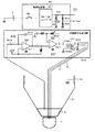
以下、この発明による位置指示器の実施形態を、図を参照しながら説明する。図1は、この発明の実施形態の位置指示器1の概念的構成およびその処理動作を概括的に説明するための図であり、位置指示器1が、静電容量式の位置検出システム2のセンサ入力面2a上に位置されている状態を示す図である。また、図2は、位置指示器1の機構的構成例を説明するための図で、図2(A)は、その一部縦断面図であり、図2(B)は、その外観の一部を示す図である。この実施形態では、位置指示器1は外観が棒状のスタイラス形状を有するものとして形成されている。 Hereinafter, embodiments of the position indicator according to the present invention will be described with reference to the drawings. FIG. 1 is a diagram for generally explaining the conceptual configuration of the position indicator 1 according to the embodiment of the present invention and the processing operation thereof, and the position indicator 1 is a capacitance type position detection system 2. It is a figure which shows the state which is positioned on the sensor input surface 2a. Further, FIG. 2 is a diagram for explaining a mechanical configuration example of the position indicator 1, FIG. 2 (A) is a partial vertical sectional view thereof, and FIG. 2 (B) is one of the appearances thereof. It is a figure which shows the part. In this embodiment, the position indicator 1 is formed so that the appearance has a rod-shaped stylus shape.

[実施形態の位置指示器の機械的構成例の説明]
この実施形態の位置指示器1は、棒状の筐体3を備える。この筐体3は、図2(A)に示すように、絶縁材料例えば合成樹脂からなる中空の円筒状形状の絶縁体部31により構成されている。そして、この実施形態では、筐体3の絶縁体部31の外表周面の少なくとも操作者が当該位置指示器1を把持する部分は、例えば金属からなる導電体部32で覆われている。
[Explanation of Mechanical Configuration Example of Position Indicator of Embodiment]
The position indicator 1 of this embodiment includes a rod-shaped housing 3. As shown in FIG. 2A, the housing 3 is composed of a hollow cylindrical insulator portion 31 made of an insulating material, for example, a synthetic resin. In this embodiment, at least a portion of the outer peripheral surface of the insulator portion 31 of the housing 3 where the operator holds the position indicator 1 is covered with a conductor portion 32 made of, for example, metal.

筐体3内には、図2(A)に示すように、プリント配線基板40と、バッテリー5と、筆圧検出ユニット9とが配設されている。筐体3の外表周面を覆う導電体部32は、図示は省略するが、このプリント配線基板40のアース導体に電気的に接続されている。 As shown in FIG. 2A, a printed wiring board 40, a battery 5, and a pen pressure detecting unit 9 are arranged in the housing 3. Although not shown, the conductor portion 32 that covers the outer peripheral surface of the housing 3 is electrically connected to the ground conductor of the printed wiring board 40.

プリント配線基板40上には、図1及び図2(A)に示すように、制御手段の例を構成する信号送信制御回路41と、無線通信モジュール42と、押釦スイッチからなるサイドスイッチ43と、当該位置指示器1の識別情報(ID)を記憶するIDメモリ44と、互いに異なる周波数f1,f2の発振信号を出力する発振器45,46と、導電パターン47a〜47eなどの配線パターンなどの他、この例では、電源スイッチ48およびLED(Light Emitting Diode)49などが配置されている。なお、図2(A)では、導電パターン47a〜47eは、説明の簡略化のため模式的に一本の導体パターンとして示しているが、導電パターン47a〜47eは、必要に応じて、複数本の導体パターンからなる場合も勿論ある。 On the printed wiring board 40, as shown in FIGS. 1 and 2A, a signal transmission control circuit 41 constituting an example of control means, a wireless communication module 42, and a side switch 43 including a push button switch are provided. In addition to the ID memory 44 that stores the identification information (ID) of the position indicator 1, the oscillators 45 and 46 that output oscillation signals of frequencies f1 and f2 that are different from each other, and the wiring patterns such as the conductive patterns 47a to 47e. In this example, a power switch 48, an LED (Light Emitting Diode) 49, and the like are arranged. In FIG. 2A, the conductive patterns 47a to 47e are schematically shown as one conductor pattern for simplification of description, but a plurality of conductive patterns 47a to 47e are shown as necessary. Of course, it may consist of the conductor pattern of.

バッテリー5は、プリント配線基板40上に構成されている電子回路及び電子部品への電源の供給源である。筆圧検出ユニット9は、後述するように、この実施形態では、芯体を構成する中心電極7に印加される筆圧に応じた静電容量を呈する可変容量コンデンサの構成とされている。 The battery 5 is a power supply source for electronic circuits and electronic components configured on the printed wiring board 40. As will be described later, the pen pressure detection unit 9 is configured as a variable capacitance capacitor that exhibits a capacitance corresponding to the pen pressure applied to the center electrode 7 constituting the core body in this embodiment.

無線通信モジュール42は、この発明の付加情報の送信部(第2の送信部)の例となる送信機能部と、位置検出システムからの信号を受信する受信部(第1の受信部)の例となる受信機能部を有するもので、この実施形態では、近距離無線通信規格のブルートゥース(登録商標)規格の無線通信モジュールの構成とされている。無線通信モジュール42は、信号送信制御回路41と接続されている。なお、この無線通信モジュール42としては、ブルートゥースに限られるものではなく、例えば赤外線通信によるものであってもよいし、あるいは、Wi−Fi(登録商標)規格の無線通信モジュールを用いてもよい。 The wireless communication module 42 is an example of a transmission function unit that is an example of a transmission unit (second transmission unit) for additional information of the present invention and a reception unit (first reception unit) that receives a signal from a position detection system. In this embodiment, the wireless communication module of the Bluetooth (registered trademark) standard of the short-range wireless communication standard is configured. The wireless communication module 42 is connected to the signal transmission control circuit 41. The wireless communication module 42 is not limited to Bluetooth, and may be, for example, infrared communication, or a Wi-Fi (registered trademark) standard wireless communication module may be used.

サイドスイッチ43、IDメモリ44及び筆圧検出ユニット9は、それぞれ付加情報発生手段を構成する。サイドスイッチ43は、そのオンまたはオフの情報を、付加情報の一例として信号送信制御回路41に供給する。IDメモリ44は、信号送信制御回路41からの読出し要求に応じて、記憶している当該位置指示器1の識別情報(ID:Identification)を、付加情報の一例として、信号送信制御回路41に出力する。筆圧検出ユニット9により構成される可変容量コンデンサは、芯体を構成する中心電極7に印加される筆圧値に応じた静電容量変化を呈し、信号送信制御回路41は、その静電容量に基づいて、付加情報の一例としての筆圧情報を生成する。 The side switch 43, the ID memory 44, and the pen pressure detection unit 9 each constitute an additional information generating means. The side switch 43 supplies the on or off information to the signal transmission control circuit 41 as an example of additional information. The ID memory 44 outputs the stored identification information (ID: Identification) of the position indicator 1 to the signal transmission control circuit 41 as an example of additional information in response to a read request from the signal transmission control circuit 41. do. The variable capacitance capacitor configured by the pen pressure detection unit 9 exhibits a capacitance change according to the pen pressure value applied to the center electrode 7 constituting the core body, and the signal transmission control circuit 41 exhibits the capacitance. Based on, the pen pressure information as an example of the additional information is generated.

発振器45及び46は、この実施形態の位置指示器1から送出する位置検出用信号を形成するための交流信号を発生し、その発生した交流信号を信号送信制御回路41に供給する。この実施形態では、発振器45は周波数f1の交流信号を発生し、発振器46は、周波数f1とは異なる周波数f2の交流信号を発生する。信号送信制御回路41は、発振器45及び発振器46に基づいて、異なる位置検出用信号を生成する。つまり、信号送信制御回路41は、発振器45及び発振器46と相まって、位置検出用信号を発生する手段を構成し、2個の発信部を構成する。そして、信号送信制御回路41は、生成した2種の位置検出用信号のいずれかを、位置指示器1から送出する位置検出用信号とする。なお、発振器45,46の代わりに、後述するアクティブ方式の複数種の構成タイプの位置指示器用のそれぞれ用の位置検出用信号を生成して発信する複数個の発信部を設け、信号送信制御回路41で選択制御するように構成してもよい。 The oscillators 45 and 46 generate an AC signal for forming a position detection signal to be transmitted from the position indicator 1 of this embodiment, and supply the generated AC signal to the signal transmission control circuit 41. In this embodiment, the oscillator 45 generates an AC signal having a frequency f1, and the oscillator 46 generates an AC signal having a frequency f2 different from the frequency f1. The signal transmission control circuit 41 generates different position detection signals based on the oscillator 45 and the oscillator 46. That is, the signal transmission control circuit 41, together with the oscillator 45 and the oscillator 46, constitutes a means for generating a position detection signal, and constitutes two transmitters. Then, the signal transmission control circuit 41 uses one of the two types of position detection signals generated as the position detection signal to be transmitted from the position indicator 1. In addition, instead of the oscillators 45 and 46, a plurality of transmitters for generating and transmitting position detection signals for each of a plurality of types of active configuration types described later are provided, and a signal transmission control circuit is provided. It may be configured to perform selection control at 41.

そして、この実施形態では、バッテリー5は、筐体3内に、図1及び図2(A)に示すように収納されるように構成されており、プリント配線基板40上の信号送信制御回路41などの電子回路部の電源電圧は、このバッテリー5にて生成される。図2(A)において、端子52は、プリント配線基板40上の電源回路部に電気的に接続されている端子である。バッテリー5の正極側電極51は、この端子52に接触して電気的に接続されている。図示は省略するが、バッテリー5の負極側電極は、プリント配線基板40のアース導体に直接に接続され、あるいは筐体3の導電体部32を経由してプリント配線基板40のアース導体に接続されている弾性変位する端子に押圧接触するようにされている。 Then, in this embodiment, the battery 5 is configured to be housed in the housing 3 as shown in FIGS. 1 and 2 (A), and the signal transmission control circuit 41 on the printed wiring board 40. The power supply voltage of the electronic circuit unit such as is generated by this battery 5. In FIG. 2A, the terminal 52 is a terminal electrically connected to the power supply circuit portion on the printed wiring board 40. The positive electrode side electrode 51 of the battery 5 is in contact with the terminal 52 and is electrically connected. Although not shown, the negative electrode side electrode of the battery 5 is directly connected to the ground conductor of the printed wiring board 40, or is connected to the ground conductor of the printed wiring board 40 via the conductor portion 32 of the housing 3. It is designed to make pressure contact with the elastically displaced terminal.

プリント配線基板40上に配置されている電源スイッチ48の操作子48aは、図2(B)に示すように、筐体3に設けられた開口部を介して、外部から操作可能に設けられている。使用者が、この操作子48aをスライド移動させることにより、電源スイッチ48をオン・オフさせることができる。なお、プリント配線基板40上には、電源スイッチ48がオンとされたときに、バッテリー5からの電圧から電源電圧を生成する電源回路部も形成されているが、図1及び図2では、説明の簡単のため省略した。 As shown in FIG. 2B, the operator 48a of the power switch 48 arranged on the printed wiring board 40 is provided so as to be operable from the outside through the opening provided in the housing 3. There is. The user can turn on / off the power switch 48 by sliding the operator 48a. A power supply circuit unit that generates a power supply voltage from the voltage from the battery 5 when the power supply switch 48 is turned on is also formed on the printed wiring board 40, which will be described in FIGS. 1 and 2. Omitted for simplicity.

筐体3を構成する中空の円筒状形状の絶縁体部31の中心線方向の一方の端部側は、図2(A)に示すように、徐々に先細となるテーパー部33とされている。このテーパー部33の外周側には、例えば環状の導電金属からなる周辺電極6が取り付けられる。周辺電極6と筐体3の外周表面の導電体部32とは、両者の間に絶縁体部31が介在することにより、絶縁されている。 As shown in FIG. 2A, one end side of the hollow cylindrical insulator portion 31 constituting the housing 3 in the center line direction is a tapered portion 33 that gradually tapers. .. A peripheral electrode 6 made of, for example, an annular conductive metal is attached to the outer peripheral side of the tapered portion 33. The peripheral electrode 6 and the conductor portion 32 on the outer peripheral surface of the housing 3 are insulated by an insulator portion 31 interposed between the peripheral electrode 6 and the conductor portion 32 on the outer peripheral surface of the housing 3.

周辺電極6は、図1に模式的に示すように、位置検出システム2と静電結合することで、この実施形態では、位置検出システムからの信号の受信部(第2の受信部)を構成する。そして、この周辺電極6は、絶縁体部31を貫通するリード導体部材61により、プリント配線基板40の導体パターン47aに電気的に接続されている。この導体パターン47aは、この例では、信号送信制御回路41の入力端に接続されている。 As shown schematically in FIG. 1, the peripheral electrode 6 is electrostatically coupled to the position detection system 2 to form a signal receiving unit (second receiving unit) from the position detection system in this embodiment. do. The peripheral electrode 6 is electrically connected to the conductor pattern 47a of the printed wiring board 40 by a lead conductor member 61 penetrating the insulator portion 31. In this example, the conductor pattern 47a is connected to the input end of the signal transmission control circuit 41.

また、この実施形態では、筐体3のテーパー部33の中空部から一端側が外部に突出するように、導電性を有する棒状体からなる中心電極7が配される。この中心電極7は、ペン形状の位置指示器1のペン先を構成する芯体となるものである。 Further, in this embodiment, the central electrode 7 made of a rod-shaped body having conductivity is arranged so that one end side projects outward from the hollow portion of the tapered portion 33 of the housing 3. The center electrode 7 serves as a core body constituting the pen tip of the pen-shaped position indicator 1.

中心電極7は、この実施形態においては、位置検出用信号を送出するための第1の送信部を構成するもので、その外部に突出する側とは反対側の端部は、プリント配線基板40に形成されている導電パターン47bに電気的に接続されるように構成されている。この導電パターン47bは、信号送信制御回路41の出力端に接続されている。なお、この実施形態では、位置指示器1は、位置検出用信号を送出しないパッシブ方式の位置指示器としても動作するもので、その場合には、中心電極7は、位置検出システム2の導体からの電荷を静電結合部を介して吸い上げる役割をすることになる。 In this embodiment, the center electrode 7 constitutes a first transmission unit for transmitting a position detection signal, and the end portion on the side opposite to the side protruding to the outside is the printed wiring board 40. It is configured to be electrically connected to the conductive pattern 47b formed in. The conductive pattern 47b is connected to the output end of the signal transmission control circuit 41. In this embodiment, the position indicator 1 also operates as a passive type position indicator that does not send a position detection signal. In that case, the center electrode 7 is connected to the conductor of the position detection system 2. It will play a role of sucking up the electric charge of the above through the electrostatic coupling part.

周辺電極6は、この中心電極7の周囲に設けられる。周辺電極6と中心電極7との組み合わせは、前述したパッシブ方式の改良方式の位置指示器用である。この実施形態では、周辺電極6と中心電極7との間には、互いの電気的干渉を、効果的に防止するためのシールド部材8が設けられる。この実施形態のシールド部材8は、中心電極7を取り囲むように設けられ、これにより、シールド部材8が周辺電極6と中心電極7との間に介在して、周辺電極6と中心電極7との間の結合容量をできるだけ小さくするようにしている。 The peripheral electrode 6 is provided around the central electrode 7. The combination of the peripheral electrode 6 and the center electrode 7 is for the above-mentioned improved passive position indicator. In this embodiment, a shield member 8 is provided between the peripheral electrode 6 and the center electrode 7 to effectively prevent electrical interference between the peripheral electrodes 6 and the center electrode 7. The shield member 8 of this embodiment is provided so as to surround the center electrode 7, whereby the shield member 8 is interposed between the peripheral electrode 6 and the center electrode 7, and the peripheral electrode 6 and the center electrode 7 are connected to each other. The coupling capacitance between them is made as small as possible.

この芯体としての中心電極7は、その外部に突出する側とは反対側の端部が、筐体3の中空部内に配設されている筆圧検出ユニット9に嵌合されることで、位置指示器1の筐体3の中空部内に係止される。なお、後述するように、中心電極7は、引き抜くことで、筆圧検出ユニット9との嵌合が外れるように構成されている。すなわち、芯体としての中心電極7は、位置指示器1に対して交換可能である。 The center electrode 7 as a core body has an end portion on the side opposite to the side protruding to the outside, which is fitted into a pen pressure detection unit 9 arranged in a hollow portion of the housing 3. It is locked in the hollow portion of the housing 3 of the position indicator 1. As will be described later, the center electrode 7 is configured to be disengaged from the pen pressure detection unit 9 by pulling it out. That is, the center electrode 7 as the core body is replaceable with respect to the position indicator 1.

筆圧検出ユニット9は、この例では、芯体としての中心電極7に加えられる圧力(筆圧)に応じた静電容量を呈する可変容量コンデンサ(例えば特開2011‐186803号公報等参照)で構成されている。この筆圧検出ユニット9で構成される可変容量コンデンサの両端の電極は、図2(A)では、導電パターン47cにより、信号送信制御回路41に接続されている。 In this example, the pen pressure detection unit 9 is a variable capacitance capacitor (see, for example, Japanese Patent Application Laid-Open No. 2011-186803) that exhibits a capacitance according to the pressure (pen pressure) applied to the center electrode 7 as a core body. It is configured. In FIG. 2A, the electrodes at both ends of the variable capacitance capacitor configured by the pen pressure detection unit 9 are connected to the signal transmission control circuit 41 by a conductive pattern 47c.

信号送信制御回路41は、無線通信モジュール42を通じて外部から受信した情報または周辺電極6を通じて受信した情報に基づいて、この実施形態の位置指示器1を、複数種の構成タイプ(モード)のいずれにするかを決定制御すると共に、その決定制御に基づいて、位置検出用信号の中心電極7を通じた送出の制御をし、さらに、付加情報の中心電極7または無線通信モジュール42を通じた送出の制御を行う。 The signal transmission control circuit 41 sets the position indicator 1 of this embodiment into any of a plurality of configuration types (modes) based on the information received from the outside through the wireless communication module 42 or the information received through the peripheral electrode 6. It is determined and controlled, and based on the determined control, the transmission of the position detection signal through the center electrode 7 is controlled, and further, the transmission of additional information is controlled through the center electrode 7 or the wireless communication module 42. conduct.

次に、図3を参照して、中心電極7、シールド部材8及び筆圧検出ユニット9の部分の詳細な構成について説明する。図3は、中心電極7、シールド部材8及び筆圧検出ユニット9の部分の断面図を示すものである。 Next, with reference to FIG. 3, a detailed configuration of the center electrode 7, the shield member 8, and the pen pressure detection unit 9 will be described. FIG. 3 shows a cross-sectional view of a portion of the center electrode 7, the shield member 8, and the pen pressure detection unit 9.

中心電極7は、図3に示すように、直径が例えば1.9mmに形成された導電性材料、例えば金属からなる芯体71を備え、この実施形態では、芯体71のペン先側の約半分が絶縁性材料からなる保護部材72により覆われている。保護部材72は、位置検出システム2のセンサ入力面2aを傷付けないようにすると共にセンサ入力面2aとの接触面積を大きくする役割と、シールド部材8及び周辺電極6に対する絶縁をより強固にする役割を有する。 As shown in FIG. 3, the center electrode 7 includes a core body 71 made of a conductive material having a diameter of, for example, 1.9 mm, for example, metal. In this embodiment, the center electrode 7 is about the pen tip side of the core body 71. Half is covered with a protective member 72 made of an insulating material. The protective member 72 has a role of not damaging the sensor input surface 2a of the position detection system 2 and increasing the contact area with the sensor input surface 2a, and a role of further strengthening the insulation of the shield member 8 and the peripheral electrodes 6. Has.

図3に示すように、シールド部材8は、この実施形態では、導電性材料で構成されている筒状体81が、その外壁面及び内壁面を含む全表面を絶縁層82で覆われた構成とされている。 As shown in FIG. 3, in this embodiment, the shield member 8 has a tubular body 81 made of a conductive material, and the entire surface including the outer wall surface and the inner wall surface thereof is covered with an insulating layer 82. It is said that.

筆圧検出ユニット9は、中心電極7に印加される筆圧を、圧力伝達部材10を通じて受けて、静電容量が可変する可変容量コンデンサの構成とされている。図3に示すように、中心電極7と圧力伝達部材10とは結合されて、シールド部材8の筒状体81の中空部内に、摺動自在の状態で収容される。圧力伝達部材10は、中心電極7の芯体71の端部71bが嵌合される芯体嵌合部11と、筆圧検出ユニット9に嵌合する突出部12とを有する。 The pen pressure detection unit 9 is configured as a variable capacitance capacitor in which the pen pressure applied to the center electrode 7 is received through the pressure transmission member 10 and the capacitance is variable. As shown in FIG. 3, the center electrode 7 and the pressure transmitting member 10 are coupled and housed in the hollow portion of the cylindrical body 81 of the shield member 8 in a slidable state. The pressure transmission member 10 has a core body fitting portion 11 to which the end portion 71b of the core body 71 of the center electrode 7 is fitted, and a protruding portion 12 to be fitted to the writing pressure detection unit 9.

そして、圧力伝達部材10の凹部11a内には、図3に示すように、中心電極7と、プリント配線基板40の信号送信制御回路41との電気的な接続を行うための端子片13が配設されており、当該端子片13からの延長部13aがプリント配線基板40の導体パターンに接続されるリード電極14に接続されている。 Then, as shown in FIG. 3, a terminal piece 13 for electrically connecting the center electrode 7 and the signal transmission control circuit 41 of the printed wiring board 40 is arranged in the recess 11a of the pressure transmission member 10. The extension portion 13a from the terminal piece 13 is connected to the lead electrode 14 connected to the conductor pattern of the printed wiring board 40.

中心電極7の芯体71は、その端部71aが、圧力伝達部材10の芯体嵌合部11の凹部11a内の端子片13に挿入(圧入)されることで、圧力伝達部材10と結合され、芯体71に印加される筆圧が圧力伝達部材10を介して後述する筆圧検出ユニット9に伝達されるようになっている。 The core body 71 of the center electrode 7 is coupled to the pressure transmission member 10 by inserting (press-fitting) the end portion 71a into the terminal piece 13 in the recess 11a of the core body fitting portion 11 of the pressure transmission member 10. Then, the writing pressure applied to the core body 71 is transmitted to the writing pressure detecting unit 9 described later via the pressure transmitting member 10.

なお、図3に示すように、筆圧検出ユニット9とシールド部材8との衝合部には、プリント配線基板40のアース導体に電気的に接続されている導電性金属板86が設けられており、シールド部材8の筒状体81の面が露出している端子部83と、この導電性金属板88と電気的に接続されている。これにより、中心電極7は、シールド部材8により電界シールドされている。 As shown in FIG. 3, a conductive metal plate 86 electrically connected to the ground conductor of the printed wiring board 40 is provided at the abutting portion between the pen pressure detection unit 9 and the shield member 8. The terminal portion 83 whose surface of the tubular body 81 of the shield member 8 is exposed is electrically connected to the conductive metal plate 88. As a result, the center electrode 7 is electrically shielded by the shield member 8.

なお、圧力伝達部材10の芯体嵌合部11は、シールド部材8の筒状体81の中空部の段差部84に係合するため、中心電極7及び圧力伝達部材10が、ペン先側に抜け落ちないようになっている。また、シールド部材8の外周面の段差部85が、図示は省略する筐体3の絶縁体部31の中空部の内壁に形成されている段部に係合することで、シールド部材8が、筐体3の絶縁体部31の中空部内において、軸心方向に移動しないように構成されている。 Since the core fitting portion 11 of the pressure transmission member 10 engages with the stepped portion 84 of the hollow portion of the cylindrical body 81 of the shield member 8, the center electrode 7 and the pressure transmission member 10 are placed on the pen tip side. It is designed not to fall out. Further, the shield member 8 is formed by engaging the stepped portion 85 on the outer peripheral surface of the shield member 8 with the step portion formed on the inner wall of the hollow portion of the insulator portion 31 of the housing 3 (not shown). It is configured so as not to move in the axial direction in the hollow portion of the insulator portion 31 of the housing 3.

筆圧検出ユニット9について、以下に説明する。この例の筆圧検出ユニット9は、例えば特許文献:特開2011−186803号公報に記載されている周知の構成の筆圧検出手段を使用したもので、中心電極7に印加される筆圧に応じて静電容量が変化する可変容量コンデンサを構成する。 The pen pressure detection unit 9 will be described below. The pen pressure detecting unit 9 of this example uses, for example, a pen pressure detecting means having a well-known configuration described in Patent Document: Japanese Patent Application Laid-Open No. 2011-186803, and is applied to the pen pressure applied to the center electrode 7. A variable capacitance capacitor whose capacitance changes accordingly is configured.

この例の筆圧検出ユニット9は、図3に示すように、絶縁性材料、例えば樹脂からなるハウジング部材91内に、誘電体92と、導電部材93と、弾性部材94と、保持部材95と、端子部材96との複数個の部品が収納されて構成されている。端子部材96は、筆圧検出ユニット9を構成する可変容量コンデンサの第1の電極を構成する。また、導電部材93と弾性部材94とは電気的に接続されて、可変容量コンデンサの第2の電極を構成する。 As shown in FIG. 3, the pen pressure detection unit 9 of this example includes a dielectric 92, a conductive member 93, an elastic member 94, and a holding member 95 in a housing member 91 made of an insulating material, for example, a resin. , A plurality of parts with the terminal member 96 are housed and configured. The terminal member 96 constitutes the first electrode of the variable capacitance capacitor that constitutes the pen pressure detection unit 9. Further, the conductive member 93 and the elastic member 94 are electrically connected to form a second electrode of the variable capacitance capacitor.

この筆圧検出ユニット9においては、中心電極7に筆圧が印加されると、当該筆圧は圧力伝達部材10を介して筆圧検出ユニット9の保持部材95に伝達され、保持部材95は、印加された筆圧に応じて、導電部材93を誘電体92側に移動させる。すると、導電部材93と誘電体92との接触面積が印加された筆圧に応じて変化し、第1の電極と第2の電極との間に形成される可変容量コンデンサの静電容量が、印加された筆圧に応じて可変される。 In this pen pressure detection unit 9, when a pen pressure is applied to the center electrode 7, the pen pressure is transmitted to the holding member 95 of the pen pressure detection unit 9 via the pressure transmission member 10, and the holding member 95 receives the pen pressure. The conductive member 93 is moved to the dielectric 92 side according to the applied writing pressure. Then, the contact area between the conductive member 93 and the dielectric 92 changes according to the applied writing pressure, and the capacitance of the variable capacitor formed between the first electrode and the second electrode is changed. It is variable according to the applied pen pressure.

[実施形態の位置指示器1の内部電子回路の構成例の説明]
この実施形態においては、位置指示器1と共に使用される位置検出システム2としては、前述したようにパッシブ方式、パッシブ方式の改良方式、アクティブ方式など、複数の構成タイプのものが存在する。この実施形態では、位置検出システム2は、位置指示器1の無線通信モジュール42と通信可能な無線通信モジュールを備える場合、当該無線通信モジュールにより、位置検出システムが動作可能な構成タイプを示すペン種情報を、位置指示器1に送信するようにする。位置指示器1は、無線通信モジュール42の受信機能(第1の受信部)により、当該位置検出システムからのペン種情報を受信し、当該受信したペン種情報に基づいて、いずれの構成タイプ(モード)の位置指示器とすべきかを決定し、その決定した構成タイプの位置指示器の構成となるように制御する。
[Explanation of Configuration Example of Internal Electronic Circuit of Position Indicator 1 of the Embodiment]
In this embodiment, as the position detection system 2 used together with the position indicator 1, there are a plurality of configuration types such as a passive system, an improved passive system, and an active system as described above. In this embodiment, when the position detection system 2 includes a wireless communication module capable of communicating with the wireless communication module 42 of the position indicator 1, the pen type indicating a configuration type in which the position detection system can operate by the wireless communication module. The information is transmitted to the position indicator 1. The position indicator 1 receives pen type information from the position detection system by the receiving function (first receiving unit) of the wireless communication module 42, and based on the received pen type information, any configuration type (1st receiving unit). The position indicator of the mode) is determined, and the configuration of the position indicator of the determined configuration type is controlled.

位置検出システム2側からの送信信号を受けるパッシブ方式あるいはパッシブ方式の改良方式の構成タイプの位置指示器の場合には、位置指示器1は、周辺電極6(第2の受信部)を通じて、当該位置検出システムからの信号を受信することで、いずれの構成タイプの位置指示器とすべきかを決定し、その決定したタイプの位置指示器の構成となるように制御することができる。 In the case of a passive type or an improved type of passive type position indicator that receives a transmission signal from the position detection system 2 side, the position indicator 1 is said to be connected through the peripheral electrode 6 (second receiving unit). By receiving the signal from the position detection system, it is possible to determine which configuration type of position indicator should be used and control the configuration of the determined type of position indicator.

この場合に、パッシブ方式とパッシブ方式の改良方式とでは、位置検出システムからの信号の周波数の違いや、信号内容の違い(拡散符号の違いや変調方式の違い等)があることから、位置指示器1は、それらの違いを判別し、その判別結果によりいずれの構成タイプの位置指示器とすべきかを決定する。この場合には、無線通信モジュールを通じて、位置検出システムから、構成タイプの情報が得られないときにも、いずれの構成タイプ(モード)の位置指示器とすべきかを判定することができる。 In this case, since there is a difference in the frequency of the signal from the position detection system and a difference in the signal content (difference in the diffusion code, difference in the modulation method, etc.) between the passive method and the improved method of the passive method, the position is instructed. The vessel 1 discriminates between them, and determines which configuration type position indicator should be used based on the discriminant result. In this case, it is possible to determine which configuration type (mode) of the position indicator should be used even when the configuration type information cannot be obtained from the position detection system through the wireless communication module.

位置指示器1の信号送信制御回路41は、上述した、位置検出システム2から無線通信モジュール42を通じて受信した情報、あるいは、周辺電極6を通じて受信した信号、に基づく位置指示器1の構成タイプ(モード)の決定処理を行うと共に、位置指示器1を決定した構成タイプ(モード)となるように制御する処理も行う。 The signal transmission control circuit 41 of the position indicator 1 is a configuration type (mode) of the position indicator 1 based on the information received from the position detection system 2 through the wireless communication module 42 or the signal received through the peripheral electrode 6 described above. ), And also a process of controlling the position indicator 1 so as to have the determined configuration type (mode).

図4は、この実施形態の位置指示器1の筐体3内のプリント配線基板40上に形成されている電子回路の構成を示すブロック図であり、主として、信号送信制御回路41の内部詳細構成例を示す図である。 FIG. 4 is a block diagram showing a configuration of an electronic circuit formed on the printed wiring board 40 in the housing 3 of the position indicator 1 of this embodiment, and is mainly an internal detailed configuration of the signal transmission control circuit 41. It is a figure which shows an example.

図4に示すように、信号送信制御回路41は、例えばIC(Integrated Circuit)からなる制御部410と、ペン種判断部411と、中心電極送信信号生成部412と、無線送信信号生成部413と、位置検出用信号選択用のスイッチ回路414と、帰還信号生成回路415と、パッシブ方式の位置指示器と、パッシブ方式の改良方式及びアクティブ方式の位置指示器とを切り替えるためのスイッチ回路416、417とを含んで構成されている。 As shown in FIG. 4, the signal transmission control circuit 41 includes, for example, a control unit 410 made of an IC (Integrated Circuit), a pen type determination unit 411, a center electrode transmission signal generation unit 412, and a radio transmission signal generation unit 413. , Switch circuit 414 for position detection signal selection, feedback signal generation circuit 415, passive type position indicator, and switch circuit 416, 417 for switching between passive type improved method and active type position indicator. It is configured to include and.

制御部410には、筆圧検出ユニット9で構成される可変容量コンデンサが接続されており、制御部410は、筆圧検出ユニット9で構成される可変容量コンデンサの静電容量から、中心電極7に印加される圧力(筆圧値)を算出する。また、サイドスイッチ43のオン、オフの状態信号が制御部410に供給される。制御部410は、このサイドスイッチ43のオン、オフの状態信号から、サイドスイッチ43に関する付加情報であるサイドスイッチ情報を生成する。また、IDメモリ44が制御部410に接続されており、制御部410は、必要に応じてこのIDメモリ44から位置指示器1の識別情報(ID)を読み出して取得するようにする。なお、IDメモリ44は予め識別情報を記憶したものを位置指示器1に収納するようにしてもよいし、記憶IDメモリ44の記憶内容である識別情報を、例えば無線通信モジュール42を通じて受信される、位置検出システム2からのコマンドにより書き替えることができるように構成してもよい。 A variable capacitance capacitor composed of the pen pressure detection unit 9 is connected to the control unit 410, and the control unit 410 is based on the capacitance of the variable capacitance capacitor composed of the pen pressure detection unit 9 to the center electrode 7. Calculate the pressure (pen pressure value) applied to. Further, the on / off status signal of the side switch 43 is supplied to the control unit 410. The control unit 410 generates side switch information, which is additional information about the side switch 43, from the on / off status signals of the side switch 43. Further, the ID memory 44 is connected to the control unit 410, and the control unit 410 reads and acquires the identification information (ID) of the position indicator 1 from the ID memory 44 as needed. The ID memory 44 may store the identification information stored in advance in the position indicator 1, or the identification information which is the storage content of the storage ID memory 44 is received, for example, through the wireless communication module 42. , It may be configured so that it can be rewritten by a command from the position detection system 2.

制御部410は、ペン種判断部411からのペン種判断結果に基づく情報に応じて、複数種の付加情報、この例では、筆圧情報、サイドスイッチ情報、識別情報のそれぞれについて、中心電極7から送出するか、無線通信モジュール42から無線送信するかを制御するようにする。 The control unit 410 has a center electrode 7 for each of a plurality of types of additional information, in this example, pen pressure information, side switch information, and identification information, according to the information based on the pen type determination result from the pen type determination unit 411. It is controlled whether it is transmitted from the wireless communication module 42 or wirelessly transmitted from the wireless communication module 42.

制御部410は、中心電極7を通じて送出する付加情報は、中心電極送信信号生成部412に供給し、無線通信モジュール42を通じて送出する付加情報は、無線送信信号生成部413に供給する。 The control unit 410 supplies the additional information transmitted through the center electrode 7 to the center electrode transmission signal generation unit 412, and supplies the additional information transmitted through the radio communication module 42 to the radio transmission signal generation unit 413.

中心電極送信信号生成部412は、中心電極7に接続されており、後述するように、送出すべき付加情報は、位置検出用信号と共に中心電極7を通じて位置検出システム2に送出するようにする。無線送信信号生成部413は、無線通信モジュール42の送信部421に接続されており、送出すべき付加情報は、この送信部421を通じて位置検出システム2に無線送信される。 The center electrode transmission signal generation unit 412 is connected to the center electrode 7, and as will be described later, additional information to be transmitted is transmitted to the position detection system 2 through the center electrode 7 together with the position detection signal. The wireless transmission signal generation unit 413 is connected to the transmission unit 421 of the wireless communication module 42, and the additional information to be transmitted is wirelessly transmitted to the position detection system 2 through the transmission unit 421.

中心電極送信信号生成部412には、スイッチ回路414の制御部410による切替選択に応じて、発振器45からの周波数f1の交流信号、発振器46からの周波数f2の交流信号が、送出すべき位置検出用信号を生成するための信号として供給されると共に、帰還信号生成回路415からの帰還信号が、送出すべき位置検出用信号として供給される。帰還信号生成回路415は、周辺電極6を通じて位置検出システム2から受信した信号を、この例では、増幅して信号増強し、更に位相反転するようにする。この帰還信号生成回路415の構成例及び処理例については、後で詳述する。制御部410は、ペン種判断部411からのペン種判断結果に基づく情報に基づいてスイッチ回路414の切替選択信号を生成する。 The center electrode transmission signal generation unit 412 detects the position where the AC signal of frequency f1 from the oscillator 45 and the AC signal of frequency f2 from the oscillator 46 should be transmitted according to the switching selection by the control unit 410 of the switch circuit 414. Along with being supplied as a signal for generating a signal for generation, the feedback signal from the feedback signal generation circuit 415 is supplied as a signal for position detection to be transmitted. The feedback signal generation circuit 415 amplifies the signal received from the position detection system 2 through the peripheral electrode 6 to enhance the signal in this example, and further phase-inverts the signal. A configuration example and a processing example of the feedback signal generation circuit 415 will be described in detail later. The control unit 410 generates a switching selection signal of the switch circuit 414 based on the information based on the pen type determination result from the pen type determination unit 411.

また、中心電極送信信号生成部412と中心電極7との接続部は、スイッチ回路416を通じて、筐体3の導電体部32に接続されている。また、周辺電極6は、スイッチ回路417を通じて筐体3の導電体部32に接続されている。そして、これらスイッチ回路416,417は、制御部410からのオン・オフ制御信号により切り替えられる。制御部410は、ペン種判断部411からのペン種判断結果に基づく情報に基づいてスイッチ回路416,417のオン・オフ制御信号を生成する。 Further, the connection portion between the center electrode transmission signal generation unit 412 and the center electrode 7 is connected to the conductor portion 32 of the housing 3 through the switch circuit 416. Further, the peripheral electrode 6 is connected to the conductor portion 32 of the housing 3 through the switch circuit 417. Then, these switch circuits 416 and 417 are switched by an on / off control signal from the control unit 410. The control unit 410 generates an on / off control signal for the switch circuits 416 and 417 based on the information based on the pen type determination result from the pen type determination unit 411.

ペン種判断部411は、ペン種テーブルメモリ4111と、判断処理部4112とで構成されている。ペン種判断部411の判断処理部4112には、無線通信モジュール42の受信部422で受信した位置検出システム2からの情報が供給されると共に、周辺電極6を通じて位置検出システム2から受信した信号が供給される。 The pen type determination unit 411 includes a pen type table memory 4111 and a determination processing unit 4112. The information from the position detection system 2 received by the reception unit 422 of the wireless communication module 42 is supplied to the judgment processing unit 4112 of the pen type determination unit 411, and the signal received from the position detection system 2 through the peripheral electrode 6 is supplied. Be supplied.

ペン種テーブルメモリ4111には、位置指示器1の複数種の構成タイプと、それぞれの構成タイプの位置指示器において、位置検出用信号の送出の有無及び送出する位置検出用信号を生成するための発振器の周波数、また、付加情報を中心電極7から送出するか、無線通信モジュール42を通じて送信するかのペン種テーブル情報が記憶されている。このペン種テーブル情報は、予めペン種テーブルメモリ4111に記憶されていてもよいが、この例では、無線通信モジュール42を通じて、位置検出システム2からのコマンドにより書き込み及び書き替えができるように構成されている。 In the pen type table memory 4111, the presence / absence of transmission of the position detection signal and the generation of the position detection signal to be transmitted in the plurality of configuration types of the position indicator 1 and the position indicator of each configuration type. The frequency of the oscillator and the pen type table information of whether to transmit additional information from the center electrode 7 or through the wireless communication module 42 are stored. This pen type table information may be stored in the pen type table memory 4111 in advance, but in this example, it is configured so that it can be written and rewritten by a command from the position detection system 2 through the wireless communication module 42. ing.

判断処理部4112は、無線通信モジュール42の受信部422で受信した位置検出システム2からの情報、あるいは、周辺電極6を通じて位置検出システム2のセンサ部から受信した信号を判別すると共に、ペン種テーブルメモリ4111のペン種テーブル情報を参照して、位置指示器1と共に使用しようとする位置検出システム2に適合する位置指示器の構成タイプを判断する。そして、その判断結果に基づいて、中心電極7からの信号送出の有無、中心電極7から送出する位置検出用信号及び付加情報が何であるかについての情報、無線通信モジュール42を通じて送信する付加情報が何であるかについての情報を生成して、その生成した情報を制御部410に供給する。 The determination processing unit 4112 determines the information received from the position detection system 2 received by the reception unit 422 of the wireless communication module 42 or the signal received from the sensor unit of the position detection system 2 through the peripheral electrode 6, and also determines the pen type table. With reference to the pen type table information of the memory 4111, the configuration type of the position indicator suitable for the position detection system 2 to be used together with the position indicator 1 is determined. Then, based on the determination result, information on whether or not a signal is transmitted from the center electrode 7, information about what is the position detection signal and additional information transmitted from the center electrode 7, and additional information transmitted through the wireless communication module 42 is obtained. Information about what is generated is generated, and the generated information is supplied to the control unit 410.

制御部410は、ペン種判断部411からの情報に基づいて、スイッチ回路414の切替選択信号及びスイッチ回路416,417のオン・オフ制御信号を生成して、それらのスイッチ回路414及び416,417に供給すると共に、中心電極送信信号生成部412に供給する付加情報、無線送信信号生成部413に供給する付加情報を決定して、それぞれ供給する。 The control unit 410 generates a switching selection signal of the switch circuit 414 and an on / off control signal of the switch circuits 416 and 417 based on the information from the pen type determination unit 411, and these switch circuits 414 and 416,417. The additional information to be supplied to the center electrode transmission signal generation unit 412 and the additional information to be supplied to the radio transmission signal generation unit 413 are determined and supplied to the center electrode transmission signal generation unit 412.

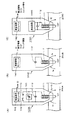
図5は、ペン種判断部411のペン種テーブル情報の一例を示すものである。この図5の例は、構成タイプ1〜構成タイプ5(モード1〜モード5)の5種の位置指示器についてのテーブル情報である。ペン種判断部411は、位置指示器の構成タイプ(モード)を判定した後、このペン種テーブル情報を参照して、制御部410に供給する制御情報を生成する。以下に、この実施形態の位置指示器1において、各構成タイプ(モード)が、制御部410による制御により切替構成されることを説明する。 FIG. 5 shows an example of pen type table information of the pen type determination unit 411. The example of FIG. 5 is table information about five types of position indicators of configuration type 1 to configuration type 5 (modes 1 to 5). After determining the configuration type (mode) of the position indicator, the pen type determination unit 411 refers to the pen type table information and generates control information to be supplied to the control unit 410. Hereinafter, in the position indicator 1 of this embodiment, it will be described that each configuration type (mode) is switched and configured by the control by the control unit 410.

構成タイプ1(モード1)は、パッシブ方式の位置指示器であり、中心電極7からは信号は送信せず、付加情報は、全て無線通信モジュール42を通じて送信する。すなわち、位置指示器1の信号送信制御回路41において、ペン種判断部411でこの構成タイプ1(モード1)と判断すると、制御部410は、スイッチ回路416,417をオンとし、また、中心電極送信信号生成部412を非動作の状態とされる。スイッチ回路417は、オフであってもよい。そして、制御部410は、全ての付加情報を無線送信信号生成部413を通じて無線通信モジュール42の送信部421を通じて位置検出システム2に送信するように制御する。なお、識別情報は、付加情報として送信する必要がない場合もある。 The configuration type 1 (mode 1) is a passive type position indicator, and no signal is transmitted from the center electrode 7, and all additional information is transmitted through the wireless communication module 42. That is, in the signal transmission control circuit 41 of the position indicator 1, when the pen type determination unit 411 determines this configuration type 1 (mode 1), the control unit 410 turns on the switch circuits 416 and 417 and also turns on the center electrode. The transmission signal generation unit 412 is put into a non-operating state. The switch circuit 417 may be off. Then, the control unit 410 controls to transmit all the additional information to the position detection system 2 through the transmission unit 421 of the wireless communication module 42 through the wireless transmission signal generation unit 413. The identification information may not need to be transmitted as additional information.

構成タイプ2(モード2)は、パッシブ方式の改良方式の位置指示器である。ペン種判断部411でこの構成タイプ2(モード2)と判断された場合には、ペン種判断部411からの情報に基づいて、制御部410は、スイッチ回路416,417はオフとし、スイッチ回路414は、帰還信号生成回路415からの信号を選択する状態に切り替える。そして、付加情報は、全て制御部410から無線送信信号生成部413を通じて無線通信モジュール42の送信部421を通じて位置検出システム2に送信するように制御する。なお、識別情報は、付加情報として送信する必要がない場合もある。 Configuration type 2 (mode 2) is an improved passive position indicator. When the pen type determination unit 411 determines this configuration type 2 (mode 2), the control unit 410 turns off the switch circuits 416 and 417 and switches circuits based on the information from the pen type determination unit 411. 414 switches to a state of selecting a signal from the feedback signal generation circuit 415. Then, all the additional information is controlled to be transmitted from the control unit 410 to the position detection system 2 through the transmission unit 421 of the wireless communication module 42 through the wireless transmission signal generation unit 413. The identification information may not need to be transmitted as additional information.

構成タイプ3(モード3)は、アクティブ方式の位置指示器の第1のタイプである。ペン種判断部411でこの構成タイプ3(モード3)と判断された場合には、ペン種判断部411からの情報に基づいて、制御部410は、スイッチ回路416はオフ、スイッチ回路417はオンとし、スイッチ回路414は、この例では、周波数f1の発振器45からの交流信号を選択する状態に切り替える。そして、付加情報は、全て制御部410から無線送信信号生成部413を通じて無線通信モジュール42の送信部421を通じて位置検出システム2に送信するように制御する。なお、識別情報は、付加情報として送信する必要がない場合もある。 Configuration type 3 (mode 3) is the first type of active position indicator. When the pen type determination unit 411 determines this configuration type 3 (mode 3), the control unit 410 turns off the switch circuit 416 and turns on the switch circuit 417 based on the information from the pen type determination unit 411. In this example, the switch circuit 414 switches to a state in which an AC signal from the oscillator 45 having a frequency f1 is selected. Then, all the additional information is controlled to be transmitted from the control unit 410 to the position detection system 2 through the transmission unit 421 of the wireless communication module 42 through the wireless transmission signal generation unit 413. The identification information may not need to be transmitted as additional information.

構成タイプ4(モード4)は、アクティブ方式の位置指示器の第2のタイプである。ペン種判断部411でこの構成タイプ4(モード4)と判断された場合には、ペン種判断部411からの情報に基づいて、制御部410は、スイッチ回路416はオフ、スイッチ回路417はオンとし、スイッチ回路414は、この例では、周波数f2の発振器46からの交流信号を選択する状態に切り替える。そして、付加情報のうち筆圧情報とサイドスイッチ情報とは中心電極7から位置検出用信号と共に送出され、識別情報IDは、無線送信信号生成部413を通じて無線通信モジュール42の送信部421を通じて位置検出システム2に送信するように制御する。 Configuration type 4 (mode 4) is a second type of active position indicator. When the pen type determination unit 411 determines this configuration type 4 (mode 4), the control unit 410 turns off the switch circuit 416 and turns on the switch circuit 417 based on the information from the pen type determination unit 411. In this example, the switch circuit 414 switches to a state in which the AC signal from the oscillator 46 having the frequency f2 is selected. Then, among the additional information, the pen pressure information and the side switch information are transmitted from the center electrode 7 together with the position detection signal, and the identification information ID is position detected through the transmission unit 421 of the wireless communication module 42 through the wireless transmission signal generation unit 413. Control to send to system 2.

構成タイプ5(モード5)は、アクティブ方式の位置指示器の第2のタイプである。ペン種判断部411でこの構成タイプ5(モード5)と判断された場合には、ペン種判断部411からの情報に基づいて、制御部410は、スイッチ回路416はオフ、スイッチ回路417はオンとし、スイッチ回路414は、この例では、周波数f2の発振器46からの交流信号を選択する状態に切り替える。そして、付加情報の全ては中心電極7から位置検出用信号と共に送出するように制御する。 Configuration type 5 (mode 5) is a second type of active position indicator. When the pen type determination unit 411 determines this configuration type 5 (mode 5), the control unit 410 turns off the switch circuit 416 and turns on the switch circuit 417 based on the information from the pen type determination unit 411. In this example, the switch circuit 414 switches to a state in which the AC signal from the oscillator 46 having the frequency f2 is selected. Then, all of the additional information is controlled to be transmitted from the center electrode 7 together with the position detection signal.

以上のようにして、信号送信制御回路41は、無線通信モジュール42の受信部422及び周辺電極6を通じて位置検出システム2のセンサ部から受信した情報及び信号に基づいて、位置指示器の構成タイプを判断して、位置指示器1を、判断した構成タイプの位置指示器の構成とするようにする。したがって、この実施形態の位置指示器1は、種々の方式の位置検出システム2に対応した種々の構成タイプの位置指示器を、自動的に構成して、使用することができる。つまり、種々の方式の複数の位置検出システム2に対して、この実施形態の位置指示器1のみで、位置指示入力することができる。このため、種々の方式の複数の位置検出システム2にそれぞれ毎に別々の位置指示器を用意する必要がなく、非常に便利であると共に、使用者にとって、コスト的な負担も軽減されることになる。 As described above, the signal transmission control circuit 41 determines the configuration type of the position indicator based on the information and the signal received from the sensor unit of the position detection system 2 through the reception unit 422 and the peripheral electrode 6 of the wireless communication module 42. Judgment is made so that the position indicator 1 has the configuration of the position indicator of the determined configuration type. Therefore, the position indicator 1 of this embodiment can automatically configure and use various configuration types of position indicators corresponding to various types of position detection systems 2. That is, the position instruction can be input to the plurality of position detection systems 2 of various methods only by the position indicator 1 of this embodiment. Therefore, it is not necessary to prepare a separate position indicator for each of the plurality of position detection systems 2 of various methods, which is very convenient and reduces the cost burden on the user. Become.

なお、無線通信モジュール42を通じて受信する位置検出システム2からのペン種情報としては、構成タイプ1〜5のそれぞれを直接的に識別する構成タイプの情報とする場合に限られるものではなく、例えば、ペン種テーブル情報の、それぞれの構成タイプ1〜5の番号や、ペン種テーブルメモリ4111の各構成タイプのアドレスなどを間接的に示す情報であってもよい。 The pen type information received from the position detection system 2 received through the wireless communication module 42 is not limited to the case where the information of the configuration type that directly identifies each of the configuration types 1 to 5 is used, for example. The pen type table information may be information that indirectly indicates the numbers of the respective configuration types 1 to 5, the address of each configuration type of the pen type table memory 4111, and the like.

なお、図4において、ペン種判断部411の判断処理部4112、中心電極送信信号生成部412、無線送信信号生成部413の各処理機能は、制御部410がソフトウエア処理機能手段として構成することも可能である。帰還信号生成回路415も同様である。 In FIG. 4, each processing function of the judgment processing unit 4112, the center electrode transmission signal generation unit 412, and the wireless transmission signal generation unit 413 of the pen type determination unit 411 is configured by the control unit 410 as software processing function means. Is also possible. The same applies to the feedback signal generation circuit 415.

[信号送信制御回路41における処理動作例]
次に、電源スイッチ48がオンとされた後における信号送信制御回路41が実行する処理動作例を、図6及び図7のフローチャートを参照しながら説明する。
[Example of processing operation in signal transmission control circuit 41]
Next, an example of the processing operation executed by the signal transmission control circuit 41 after the power switch 48 is turned on will be described with reference to the flowcharts of FIGS. 6 and 7.

信号送信制御回路41では、まず、無線通信モジュール42の受信部422で情報を受信したか否か判別し(ステップS1)、受信したと判別したときには、受信情報はペン種情報であるか否か判別する(ステップS2)。このステップS2で、受信情報はペン種情報であると判別したときには、信号送信制御回路41は、当該受信したペン種情報に基づいて位置指示器の構成タイプ(ペン種)を判断し、ペン種テーブルメモリ4111を参照して、中心電極7及び無線通信モジュール42の送信部421から送信する信号を決定する(ステップS3)。この決定には、前述したように、中心電極7から位置検出用信号を送信するか否かの決定も含まれる。 The signal transmission control circuit 41 first determines whether or not the information has been received by the receiving unit 422 of the wireless communication module 42 (step S1), and when it is determined that the information has been received, whether or not the received information is pen type information. Determine (step S2). When it is determined in step S2 that the received information is pen type information, the signal transmission control circuit 41 determines the configuration type (pen type) of the position indicator based on the received pen type information, and determines the pen type. With reference to the table memory 4111, a signal to be transmitted from the center electrode 7 and the transmission unit 421 of the wireless communication module 42 is determined (step S3). As described above, this determination also includes the determination of whether or not to transmit the position detection signal from the center electrode 7.

ステップS3の次には、信号送信制御回路41は、中心電極7及び無線通信モジュール42の送信部421を通じてのステップS3で判断された構成タイプに応じた信号送出を実行する(ステップS4)。 Following step S3, the signal transmission control circuit 41 executes signal transmission according to the configuration type determined in step S3 through the center electrode 7 and the transmission unit 421 of the wireless communication module 42 (step S4).

そして、信号送信制御回路41は、無線通信モジュール42の受信部422を通じた位置検出システム2からの情報を、受信できなくなったか否か判別し(ステップS5)、受信できなくなってはいないと判別したときには、処理をステップS4に戻して、判断した構成タイプに応じた信号送信を続行する。 Then, the signal transmission control circuit 41 determines whether or not the information from the position detection system 2 through the receiving unit 422 of the wireless communication module 42 cannot be received (step S5), and determines that the information is not disabled. Occasionally, the process returns to step S4 to continue signal transmission according to the determined configuration type.

ステップS5で、無線通信モジュール42の受信部422を通じた位置検出システム2からの情報を、受信できなくなったと判別したときには、信号送信制御回路41は、受信できなくなってから所定時間以上経過したか否か判別する(ステップS6)。このステップS6で、所定時間以上経過してはいないと判別したときには、信号送信制御回路41は、処理をステップS4に戻して、判断した構成タイプに応じた信号送信を続行する。 When it is determined in step S5 that the information from the position detection system 2 through the receiving unit 422 of the wireless communication module 42 cannot be received, the signal transmission control circuit 41 has passed a predetermined time or more since the information could not be received. (Step S6). When it is determined in step S6 that the predetermined time or more has not elapsed, the signal transmission control circuit 41 returns the process to step S4 and continues signal transmission according to the determined configuration type.

ステップS6で、所定時間以上経過したと判別したときには、信号送信制御回路41は、中心電極7及び無線通信モジュール42の送信部421からの信号送出を休止し、位置指示器1をスリープ状態にする(ステップS7)。このスリープ状態においては、できるだけバッテリー5の消耗を軽減させて省電力化を図るために、無線通信モジュール42の受信部422、信号送信制御回路41の制御部410、ペン種判断部411への電源の供給は維持するも、その他の部分への無駄な電圧供給を停止させるようにする。 When it is determined in step S6 that the predetermined time or longer has elapsed, the signal transmission control circuit 41 suspends signal transmission from the center electrode 7 and the transmission unit 421 of the wireless communication module 42, and puts the position indicator 1 into a sleep state. (Step S7). In this sleep state, in order to reduce the consumption of the battery 5 as much as possible and save power, the power supply to the receiving unit 422 of the wireless communication module 42, the control unit 410 of the signal transmission control circuit 41, and the pen type determination unit 411. The supply of power is maintained, but the unnecessary voltage supply to other parts is stopped.

そして、このステップS7の次には、信号送信制御回路41は、処理をステップS1に戻し、上述したステップS1以降の処理を繰り返す。 Then, after this step S7, the signal transmission control circuit 41 returns the processing to step S1 and repeats the processing after step S1 described above.

ステップS1で無線通信モジュール42の受信部422で情報を受信してはいないと判別したとき、また、ステップS2で、受信情報はペン種情報ではないと判別したときには、信号送信制御回路41は、周辺電極6を通じて信号を受信したか否か判別する(図7のステップS11)。このステップS11で、周辺電極6を通じて信号を受信してはいないと判別したときには、信号送信制御回路41は、スイッチ回路416をオンとして、中心電極7を導電体部32を通じてプリント配線基板40のアース導体(グランド)に接続するようにして、構成タイプ1の状態とする(ステップS18)。そして、このステップS18の次には、信号送信制御回路41は、処理を図6のステップS1に戻し、このステップS1以降の処理を繰り返す。 When it is determined in step S1 that the receiving unit 422 of the wireless communication module 42 has not received information, and when it is determined in step S2 that the received information is not pen type information, the signal transmission control circuit 41 determines. It is determined whether or not a signal has been received through the peripheral electrode 6 (step S11 in FIG. 7). When it is determined in step S11 that no signal has been received through the peripheral electrodes 6, the signal transmission control circuit 41 turns on the switch circuit 416 and grounds the center electrode 7 through the conductor portion 32 to the printed wiring board 40. It is connected to the conductor (ground) to be in the state of configuration type 1 (step S18). Then, after this step S18, the signal transmission control circuit 41 returns the process to step S1 of FIG. 6 and repeats the processes after this step S1.

そして、ステップS11で、周辺電極6を通じて信号を受信したと判別したときには、受信信号からペン種の判断は可能であるか否か判別する(ステップS12)。このステップS12で、ペン種の判断は可能ではないと判別したときには、信号送信制御回路41は、スイッチ回路416をオンとして、中心電極7を導電体部32を通じてプリント配線基板40のアース導体(グランド)に接続するようにして、構成タイプ1の状態とする(ステップS18)。そして、このステップS18の次には、信号送信制御回路41は、処理を図6のステップS1に戻し、このステップS1以降の処理を繰り返す。 Then, when it is determined in step S11 that the signal has been received through the peripheral electrode 6, it is determined whether or not the pen type can be determined from the received signal (step S12). When it is determined in step S12 that the pen type cannot be determined, the signal transmission control circuit 41 turns on the switch circuit 416 and passes the center electrode 7 through the conductor portion 32 to the ground conductor (ground) of the printed wiring board 40. ) To be in the state of configuration type 1 (step S18). Then, after this step S18, the signal transmission control circuit 41 returns the process to step S1 of FIG. 6 and repeats the processes after this step S1.

ステップS12で、ペン種の判断は可能であると判別したときには、信号送信制御回路41は、当該受信した信号に基づいて位置指示器の構成タイプ(ペン種)を判断し、ペン種テーブル4111を参照して、中心電極7及び無線通信モジュール42の送信部421から送信する信号を決定する(ステップS13)。この決定には、前述したように、中心電極7から位置検出用信号を送信するか否かの決定も含まれる。 When it is determined in step S12 that the pen type can be determined, the signal transmission control circuit 41 determines the configuration type (pen type) of the position indicator based on the received signal, and displays the pen type table 4111. With reference to this, a signal to be transmitted from the center electrode 7 and the transmission unit 421 of the wireless communication module 42 is determined (step S13). As described above, this determination also includes the determination of whether or not to transmit the position detection signal from the center electrode 7.

ステップS13の次には、信号送信制御回路41は、中心電極7及び無線通信モジュール42の送信部421を通じてのステップS13で判断された構成タイプに応じた信号送出を実行する(ステップS14)。 Following step S13, the signal transmission control circuit 41 executes signal transmission according to the configuration type determined in step S13 through the center electrode 7 and the transmission unit 421 of the wireless communication module 42 (step S14).

そして、信号送信制御回路41は、周辺電極6を通じた信号の受信ができなくなったか否か判別し(ステップS15)、受信ができなくなってはいないと判別したときには、処理をステップS14に戻して、判断した構成タイプに応じた信号送信を続行する。 Then, the signal transmission control circuit 41 determines whether or not the signal cannot be received through the peripheral electrode 6 (step S15), and when it is determined that the signal cannot be received, returns the process to step S14. Continue signal transmission according to the determined configuration type.

ステップS15で、周辺電極6を通じた信号の受信ができなくなったと判別したときには、信号送信制御回路41は、受信できなくなってから所定時間以上経過したか否か判別する(ステップS16)。このステップS16で、所定時間以上経過してはいないと判別したときには、信号送信制御回路41は、処理をステップS14に戻して、判断した構成タイプに応じた信号送信を続行する。 When it is determined in step S15 that the signal cannot be received through the peripheral electrode 6, the signal transmission control circuit 41 determines whether or not a predetermined time or more has elapsed since the signal could not be received (step S16). When it is determined in step S16 that the predetermined time or more has not elapsed, the signal transmission control circuit 41 returns the process to step S14 and continues signal transmission according to the determined configuration type.

ステップS16で、所定時間以上経過したと判別したときには、信号送信制御回路41は、中心電極7及び無線通信モジュール42の送信部421からの信号送出を休止し、位置指示器1をスリープ状態にする(ステップS17)。そして、このステップS17の次には、信号送信制御回路41は、処理をステップS1に戻し、上述したステップS1以降の処理を繰り返す。 When it is determined in step S16 that the predetermined time or longer has elapsed, the signal transmission control circuit 41 suspends signal transmission from the center electrode 7 and the transmission unit 421 of the wireless communication module 42, and puts the position indicator 1 into a sleep state. (Step S17). Then, after this step S17, the signal transmission control circuit 41 returns the processing to step S1 and repeats the processing after step S1 described above.

[各種の構成タイプの位置指示器と、対応する位置検出システムの動作説明]
<構成タイプ2の位置指示器1Aと、対応する位置検出システム2A>
図8は、構成タイプ2の位置指示器1Aの主要部の回路例を示す図であり、特に、帰還信号生成回路415の回路構成例と、上記では省略した電源回路部50の回路構成例を示したものである。
[Operation description of various configuration type position indicators and corresponding position detection systems]
<Position indicator 1A of configuration type 2 and corresponding position detection system 2A>
FIG. 8 is a diagram showing a circuit example of the main part of the position indicator 1A of the configuration type 2, and in particular, a circuit configuration example of the feedback signal generation circuit 415 and a circuit configuration example of the power supply circuit unit 50 omitted above. It is shown.

電源回路部50は、DC/DCコンバータ501を備え、バッテリー5の電圧から電源電圧+Vccを生成して、信号送信制御回路41やその他に供給する。 The power supply circuit unit 50 includes a DC / DC converter 501, generates a power supply voltage + Vcc from the voltage of the battery 5, and supplies it to the signal transmission control circuit 41 and others.

そして、電源回路部50においては、DC/DCコンバータ501とバッテリー5との間に電源スイッチ48が設けられている。また、DC/DCコンバータ501の出力端とアース導体との間には、抵抗502およびLED49の直列回路が接続されている。さらに、DC/DCコンバータ501の出力端は抵抗503および抵抗504の直列接続を通じてアース導体に接続され、抵抗503および抵抗504の接続点から基準電圧Vref(=Vcc/2)が出力される。 In the power supply circuit unit 50, a power supply switch 48 is provided between the DC / DC converter 501 and the battery 5. Further, a series circuit of the resistor 502 and the LED 49 is connected between the output end of the DC / DC converter 501 and the ground conductor. Further, the output end of the DC / DC converter 501 is connected to the ground conductor through the series connection of the resistor 503 and the resistor 504, and the reference voltage Vref (= Vcc / 2) is output from the connection point of the resistor 503 and the resistor 504.

帰還信号生成回路415は、この例では信号増強処理回路として構成されるもので、センスアンプ510と、信号増幅率可変回路520と、トランス530とからなる。 The feedback signal generation circuit 415 is configured as a signal enhancement processing circuit in this example, and includes a sense amplifier 510, a signal amplification factor variable circuit 520, and a transformer 530.

この例では、センスアンプ510は、オペアンプ511と、このオペアンプ511の反転入力端子と出力端子との間に接続されるコンデンサ512とからなる。オペアンプ511の反転入力端子は、周辺電極6に接続されている接続端子513に接続されている。また、オペアンプ511の非反転入力端子には、前述した基準電圧Vrefが供給される。 In this example, the sense amplifier 510 includes an operational amplifier 511 and a capacitor 512 connected between the inverting input terminal and the output terminal of the operational amplifier 511. The inverting input terminal of the operational amplifier 511 is connected to the connection terminal 513 connected to the peripheral electrode 6. Further, the above-mentioned reference voltage Vref is supplied to the non-inverting input terminal of the operational amplifier 511.

位置指示器1Aが位置検出システム2A上にあるときには、図1に示すように、位置指示器1Aの周辺電極6と位置検出システム2Aとは、静電容量C1を介して結合している。後述するように、位置検出システム2Aには、交流信号が流れているので、この交流信号が静電容量C1および周辺電極6を介して電流信号として接続端子513に供給され、センスアンプ510に入力される。コンデンサ512は、静電容量C1を介して入力される電流信号を検出するためのものである。 When the position indicator 1A is on the position detection system 2A, as shown in FIG. 1, the peripheral electrode 6 of the position indicator 1A and the position detection system 2A are coupled via the capacitance C1. As will be described later, since an AC signal is flowing through the position detection system 2A, this AC signal is supplied to the connection terminal 513 as a current signal via the capacitance C1 and the peripheral electrode 6, and is input to the sense amplifier 510. Will be done. The capacitor 512 is for detecting a current signal input via the capacitance C1.

そして、センスアンプ510は、接続端子513を通じて電流信号として入力された交流信号を位相反転して、信号増幅率可変回路520に出力する。 Then, the sense amplifier 510 phase-inverts the AC signal input as a current signal through the connection terminal 513, and outputs the AC signal to the signal amplification factor variable circuit 520.

信号増幅率可変回路520は、オペアンプ521と、当該オペアンプ521の反転入力端子と出力端子との間に接続される可変抵抗器522とからなる。この可変抵抗器522の抵抗値を可変設定することにより、この信号増幅率可変回路520の増幅率が可変設定され、その結果として位置指示器1Aの信号検出感度が制御される。 The signal amplification factor variable circuit 520 includes an operational amplifier 521 and a variable resistor 522 connected between the inverting input terminal and the output terminal of the operational amplifier 521. By variably setting the resistance value of the variable resistor 522, the amplification factor of the signal amplification factor variable circuit 520 is variably set, and as a result, the signal detection sensitivity of the position indicator 1A is controlled.

この信号増幅率可変回路520で増幅された交流信号は、トランス530の一次巻線530aに供給される。このトランス530の一次巻線530aの巻線数n1と、二次巻線530bの巻線数n2との比は、例えば、n1:n2=1:10のように二次巻線530b側の巻線数が大きく(n1<n2)設定されている。したがって、トランス530の二次巻線530b側には、信号増幅率可変回路520の出力信号の振幅が巻線数比に応じて逓倍されて、大振幅とされた交流信号(電圧信号)が得られる。 The AC signal amplified by the signal amplification factor variable circuit 520 is supplied to the primary winding 530a of the transformer 530. The ratio of the number of windings n1 of the primary winding 530a of the transformer 530 to the number of windings n2 of the secondary winding 530b is, for example, n1: n2 = 1:10, and the winding on the secondary winding 530b side. The number of lines is set large (n1 <n2). Therefore, on the secondary winding 530b side of the transformer 530, the amplitude of the output signal of the signal amplification factor variable circuit 520 is multiplied according to the winding number ratio to obtain an AC signal (voltage signal) having a large amplitude. Be done.

トランス530の二次巻線530bの一端は、シールド部材8によりシールドされた中心電極7の棒状導体からなる芯体71に接続されている接続端子523に接続され、トランス530の二次巻線530bの他端は、プリント配線基板40のアース導体に接続される。したがって、帰還信号生成回路415により大振幅の交流信号電圧とされた出力信号は、接続端子523を通じて中心電極7に供給される。 One end of the secondary winding 530b of the transformer 530 is connected to a connection terminal 523 connected to a core body 71 formed of a rod-shaped conductor of the center electrode 7 shielded by the shield member 8, and the secondary winding 530b of the transformer 530 is connected. The other end of the is connected to the ground conductor of the printed wiring board 40. Therefore, the output signal obtained by the feedback signal generation circuit 415 as an AC signal voltage having a large amplitude is supplied to the center electrode 7 through the connection terminal 523.

位置指示器1Aが位置検出システム2A上にあるときには、位置指示器1Aの中心電極7と位置検出システム2Aとは静電容量を介して結合されているため、位置指示器1Aの中心電極7を介して位置指示器1Aから位置検出システム2Aに交流信号が帰還される。 When the position indicator 1A is on the position detection system 2A, the center electrode 7 of the position indicator 1A and the position detection system 2A are coupled via capacitance, so that the center electrode 7 of the position indicator 1A is used. An AC signal is returned from the position indicator 1A to the position detection system 2A via the position indicator 1A.

次に、この例の位置検出システム2Aについて、図9を参照して説明する。この例の位置検出システム2Aは、センサ電極が入力電極と出力電極から構成されており、位置指示器1Aが接触したタッチポイントの結合容量の変化を検出する相互容量方式の位置検出システムの構成である。 Next, the position detection system 2A of this example will be described with reference to FIG. In the position detection system 2A of this example, the sensor electrode is composed of an input electrode and an output electrode, and the position indicator 1A is configured as a mutual capacitance type position detection system that detects a change in the coupling capacitance of the touch point in contact with the sensor electrode. be.

図9に示すように、この例の位置検出システム2Aは、センサ部20Aと、送信部21と、受信部22と、無線通信部25と、制御部220Aを備えている。センサ部20Aは、センサ入力面の横方向(X軸方向)に延伸する直線状の複数個、この例ではm個の送信導体23Y1,23Y2,・・・,23Ym(mは1以上の整数)と、この送信導体23Y1〜23Ymと直交する、センサ入力面の縦方向(Y軸方向)に延伸する複数個、この例ではn個の受信導体24X1,24X2,・・・,24Xn(nは1以上の整数)とを備える。複数個の送信導体23Y1〜23YmはY軸方向に等間隔に配置され、送信部21に接続されている。また、複数個の受信導体24X1〜24XnはX軸方向に等間隔に配置され、受信部22に接続されている。 As shown in FIG. 9, the position detection system 2A of this example includes a sensor unit 20A, a transmission unit 21, a reception unit 22, a wireless communication unit 25, and a control unit 220A. The sensor unit 20A is a plurality of linear conductors extending in the lateral direction (X-axis direction) of the sensor input surface, and in this example, m transmission conductors 23Y 1 , 23Y 2 , ..., 23Y m (m is 1 or more). And a plurality of transmitting conductors 23Y 1 to 23Y m that extend in the vertical direction (Y-axis direction) of the sensor input surface, in this example, n receiving conductors 24X 1 , 24X 2 , ... ·, 24X n (n is an integer of 1 or more). A plurality of transmission conductors 23Y 1 to 23Y m are arranged at equal intervals in the Y-axis direction and are connected to the transmission unit 21. Further, a plurality of reception conductors 24X 1 ~24X n are arranged at equal intervals in the X-axis direction and is connected to the receiver 22.

なお、この明細書の以下の説明において、送信導体23Y1〜23Ym及び受信導体24X1〜24Xnについて、いずれであるかを区別する必要のないときには、それぞれ送信導体23Y及び受信導体24Xと称することにする。 In the following description of this specification, when it is not necessary to distinguish between the transmitting conductors 23Y 1 to 23Y m and the receiving conductors 24X 1 to 24X n , they are referred to as the transmitting conductor 23Y and the receiving conductor 24X, respectively. I will decide.

複数個の送信導体23Yと複数個の受信導体24Xとは、所定の間隔を隔てて配置され、互いに直交した配置関係を備えて、複数個の交点(クロスポイント)を形成する。そして、各クロスポイントでは、送信導体23Yと受信導体24Xとは、所定の静電容量を介して結合していると見なせる。 The plurality of transmitting conductors 23Y and the plurality of receiving conductors 24X are arranged at predetermined intervals, have an arrangement relationship orthogonal to each other, and form a plurality of intersections (cross points). Then, at each cross point, the transmitting conductor 23Y and the receiving conductor 24X can be regarded as being coupled via a predetermined capacitance.

送信部21は、制御部220の制御に基づいて、送信導体23Yに所定の交流信号を供給する。この場合、送信部21は、同一の交流信号を複数個の送信導体23Y1,23Y2,・・・,23Ymに、順次に1本ずつ切り替えながら供給してもよいし、互いに異なる複数個の交流信号を複数個の送信導体23Y1,23Y2,・・・,23Ymに同時に供給するようにしても良い。また、複数個の送信導体23Y1,23Y2,・・・,23Ymを複数個のグループに分け、グループ毎に異なる交流信号を用いるようにしても良い。 The transmission unit 21 supplies a predetermined AC signal to the transmission conductor 23Y based on the control of the control unit 220. In this case, the transmission unit 21 may supply the same AC signal to the plurality of transmission conductors 23Y 1 , 23Y 2 , ..., 23Y m while sequentially switching one by one, or a plurality of different transmission conductors. AC signals may be supplied to a plurality of transmitting conductors 23Y 1 , 23Y 2 , ..., 23Y m at the same time. Further, a plurality of transmission conductors 23Y 1 , 23Y 2 , ..., 23Y m may be divided into a plurality of groups, and different AC signals may be used for each group.

受信部22は、制御部220の制御に基づいて、受信導体24X1,24X2,・・・,24Xnのそれぞれに、送信導体23Yに供給された交流信号が前記所定の静電容量を介して伝達される信号成分を検出する。送信導体23Yと受信導体24Xとの間の結合静電容量が全クロスポイントにおいて等しいとすれば、位置指示器1が、センサ部20上に存在していないときには、センサ部20の全ての受信導体24X1,24X2,・・・,24Xnからは所定レベルの受信信号が受信部22において検出される。 Receiver 22, under the control of the control unit 220, the reception conductors 24X 1, 24X 2, · · ·, each of 24X n, alternating current signal supplied to the transmission conductor 23Y is via the predetermined capacitance The signal component transmitted is detected. Assuming that the coupling capacitance between the transmitting conductor 23Y and the receiving conductor 24X is equal at all crosspoints, all receiving conductors of the sensor unit 20 when the position indicator 1 is not present on the sensor unit 20. From 24X 1 , 24X 2 , ..., 24X n , a predetermined level of received signal is detected by the receiving unit 22.

これに対して、位置指示器1Aがセンサ部20Aに接触すると、その接触位置のクロスポイントを構成する送信導体23Yと受信導体24X、および当該位置指示器1Aとは静電容量を通じて結合する。すなわち、当該位置指示器1Aによって静電容量が変化することになり、位置指示器1Aが存在するクロスポイントの受信導体24Xから得られる受信信号レベルが他のクロスポイントの受信信号レベルに比較して変化することとなる。 On the other hand, when the position indicator 1A comes into contact with the sensor unit 20A, the transmitting conductor 23Y and the receiving conductor 24X forming the cross point of the contact position and the position indicator 1A are coupled through capacitance. That is, the capacitance is changed by the position indicator 1A, and the received signal level obtained from the crosspoint receiving conductor 24X in which the position indicator 1A is present is compared with the received signal level of another crosspoint. It will change.

受信部22は、複数の受信導体24X1,24X2,・・・,24Xnのうち、その受信信号のレベルの変化があった受信導体24Xを検知することで、位置指示器1Aによる指示位置を検出する。そして、図示を省略した位置検出システム2の制御部は、送信部21から交流信号を供給している送信導体23Yと、受信部22で受信信号レベルの変化のあった受信導体24Xとを検出することにより、位置指示器1Aが接触しているクロスポイントを検出する。 Receiver 22, a plurality of reception conductors 24X 1, 24X 2, · · ·, among 24X n, by detecting the reception conductor 24X which a change in the level of the received signal, the position indicated by the position indicator 1A Is detected. Then, the control unit of the position detection system 2 (not shown) detects the transmission conductor 23Y supplying the AC signal from the transmission unit 21 and the reception conductor 24X in which the reception signal level has changed in the reception unit 22. Thereby, the cross point in contact with the position indicator 1A is detected.

位置指示器1Aではなく、指がセンサ部20上に接近または接触したときにも、位置検出システム2は、同様の原理により、その指が接近または接触したクロスポイントを検出する。その場合、送信導体23Yに供給された交流信号の一部が指を通じ、また、使用者の人体を通じてグラウンドに流れる。そのため、指が存在するクロスポイントを構成する受信導体24Xの受信信号レベルが変化する。受信部22は、この受信信号レベルの変化を検出することにより、指が存在するクロスポイントを構成する受信導体24Xを検出する。 When a finger approaches or touches the sensor unit 20 instead of the position indicator 1A, the position detection system 2 detects the cross point where the finger approaches or touches by the same principle. In that case, a part of the AC signal supplied to the transmitting conductor 23Y flows to the ground through the finger and the human body of the user. Therefore, the received signal level of the receiving conductor 24X constituting the cross point where the finger exists changes. By detecting the change in the received signal level, the receiving unit 22 detects the receiving conductor 24X constituting the cross point where the finger is present.

構成タイプ1の位置指示器の場合には、指の位置検出の原理と同様にして、位置検出システム2Aは、センサ部20Aにおける指示位置の検出を行うことができる。しかし、構成タイプ1の位置指示器の場合には、指の場合のように位置検出システム2Aとの間の接触面積が大きくないため、結合容量が小さく、位置検出システム2Aは検出感度が低い。このため、構成タイプ1の位置指示器に対応する位置検出システムは、位置指示器に送信する交流信号として拡散符号を用いて、送信信号と受信信号の相関を取ることで位置指示器の指示位置を検出するなどして、検出感度の低下を補っている。 In the case of the configuration type 1 position indicator, the position detection system 2A can detect the indicated position in the sensor unit 20A in the same manner as the principle of finger position detection. However, in the case of the configuration type 1 position indicator, since the contact area with the position detection system 2A is not large as in the case of a finger, the coupling capacitance is small and the position detection system 2A has low detection sensitivity. Therefore, the position detection system corresponding to the position indicator of the configuration type 1 uses the diffusion code as the AC signal to be transmitted to the position indicator, and correlates the transmitted signal and the received signal to indicate the indicated position of the position indicator. The decrease in detection sensitivity is compensated for by detecting.

これに対して、この構成タイプ2の位置指示器1A及び位置検出システム2Aの場合には、拡散符号などを用いなくても、位置指示器1Aと位置検出システム2Aとの親和性が高く、しかも汎用性が高く、更には入力信号と出力信号との間で所定の波形相関性が確保されて、高感度にセンサ部20A上における位置検出が可能となる。 On the other hand, in the case of the position indicator 1A and the position detection system 2A of the configuration type 2, the position indicator 1A and the position detection system 2A have a high affinity without using a diffusion code or the like, and moreover. The versatility is high, and a predetermined waveform correlation is ensured between the input signal and the output signal, so that the position can be detected on the sensor unit 20A with high sensitivity.

すなわち、位置検出システム2Aのセンサ部20A上に、位置指示器1Aを接近または接触させた場合、送信導体23Yに供給された交流信号は、図1に示したように静電容量C1を介し、また、周辺電極6を介して、電流信号として接続端子513を通じて帰還信号生成回路415に入力される。 That is, when the position indicator 1A is approached or brought into contact with the sensor unit 20A of the position detection system 2A, the AC signal supplied to the transmission conductor 23Y passes through the capacitance C1 as shown in FIG. Further, it is input to the feedback signal generation circuit 415 as a current signal through the connection terminal 513 via the peripheral electrode 6.

帰還信号生成回路415に入力された交流信号(電流信号)は、センスアンプ510で位相反転された後、信号増幅率可変回路520において増幅されるとともに、トランス530により昇圧(逓倍)されて信号増強されて、電圧信号として接続端子523を通じて中心電極7に供給される。すなわち、周辺電極6を介してセンサ部20Aから帰還信号生成回路415に入力された交流信号は、帰還信号生成回路415において、逆相とされ、また大振幅の信号とされて中心電極7を通じて、センサ部20Aに帰還される。 The AC signal (current signal) input to the feedback signal generation circuit 415 is phase-inverted by the sense amplifier 510, amplified by the signal amplification factor variable circuit 520, and boosted (multiplied) by the transformer 530 to enhance the signal. Then, it is supplied as a voltage signal to the center electrode 7 through the connection terminal 523. That is, the AC signal input from the sensor unit 20A to the feedback signal generation circuit 415 via the peripheral electrode 6 has the opposite phase in the feedback signal generation circuit 415 and is regarded as a large amplitude signal through the center electrode 7. It is returned to the sensor unit 20A.

この場合に、位置指示器1Aの中心電極7から位置検出システム2Aのセンサ部20Aに帰還される交流信号は、送信導体23Yに供給される交流信号とは逆相の増強された信号であるので、位置指示器1Aは、受信導体24Xの受信信号における交流信号の変化を、より増大させるように機能する。このため、位置検出システム2Aは、位置指示器1Aの接触位置を高感度で検出することが可能となる。なお、位置指示器1Aのアース導体が人体と接続されることで検出動作が一層安定化される。すなわち、この実施形態では、位置指示器1Aの筐体3は、プリント配線基板40のアース導体に接続されている導電体部32で覆われている。このため、位置検出システム2Aにおいて送信導体23Yに供給された交流信号は、位置指示器1Aを通じ、使用者の人体を通じてグランドに流れることで、信号検出動作の一層の安定化を図ることができる。 In this case, the AC signal returned from the center electrode 7 of the position indicator 1A to the sensor unit 20A of the position detection system 2A is an enhanced signal having an opposite phase to the AC signal supplied to the transmission conductor 23Y. The position indicator 1A functions to further increase the change in the AC signal in the received signal of the receiving conductor 24X. Therefore, the position detection system 2A can detect the contact position of the position indicator 1A with high sensitivity. The detection operation is further stabilized by connecting the ground conductor of the position indicator 1A to the human body. That is, in this embodiment, the housing 3 of the position indicator 1A is covered with the conductor portion 32 connected to the ground conductor of the printed wiring board 40. Therefore, the AC signal supplied to the transmission conductor 23Y in the position detection system 2A flows to the ground through the human body of the user through the position indicator 1A, so that the signal detection operation can be further stabilized.

また、位置検出システム2Aのセンサ部20Aの送信導体23Yでの電圧をVとし、この実施形態の位置指示器1Aの中心電極7の電圧をeとし、周辺電極6と中心電極7との間の静電容量をC2(図1参照)とすると、
e≦C1/C2・V
なる関係がある。このため、周辺電極6と中心電極7との間の静電容量C2は、できるだけ小さい方が、中心電極7の電位eを高くするのに有利である。
Further, the voltage at the transmission conductor 23Y of the sensor unit 20A of the position detection system 2A is V, the voltage of the center electrode 7 of the position indicator 1A of this embodiment is e, and the voltage between the peripheral electrode 6 and the center electrode 7 is set. Assuming that the capacitance is C2 (see Fig. 1),
e ≦ C1 / C2 ・ V
There is a relationship. Therefore, when the capacitance C2 between the peripheral electrode 6 and the center electrode 7 is as small as possible, it is advantageous to increase the potential e of the center electrode 7.

このために、この実施形態の位置指示器1においては、周辺電極6と中心電極7との間にはシールド部材8を介在させることで、両者の結合をできるだけ小さくするようにしている。したがって、この実施形態の位置指示器1では、シールド部材8を介在させることによって、周辺電極6と中心電極7との間の静電容量C2は小さくなり、電圧eを大きくすることができ、効率よく感度を高めることができる。 Therefore, in the position indicator 1 of this embodiment, the shield member 8 is interposed between the peripheral electrode 6 and the center electrode 7 so that the coupling between the two is made as small as possible. Therefore, in the position indicator 1 of this embodiment, the capacitance C2 between the peripheral electrode 6 and the center electrode 7 can be reduced and the voltage e can be increased by interposing the shield member 8, and the efficiency can be increased. The sensitivity can be increased well.

上述した実施形態の位置指示器1Aは、周辺電極6で、位置検出システム2Aからの交流信号を受信し、中心電極7から、信号増強した出力交流信号を位置検出システム2Aに帰還させる構成である。しかし、位置検出システム2Aからの交流信号を受信するための電極を中心電極7とし、信号増強した交流信号を位置検出システム2に帰還させるための電極を周辺電極6としても良い。 The position indicator 1A of the above-described embodiment has a configuration in which the peripheral electrode 6 receives the AC signal from the position detection system 2A, and the signal-enhanced output AC signal is returned to the position detection system 2A from the center electrode 7. .. However, the electrode for receiving the AC signal from the position detection system 2A may be the center electrode 7, and the electrode for returning the signal-enhanced AC signal to the position detection system 2 may be the peripheral electrode 6.

なお、図9に示すように、この構成タイプ2の位置指示器1Aは、筆圧情報、サイドスイッチ情報及び識別情報は、無線通信モジュール42から位置検出システム2Aの無線通信部25に無線送信されるものである。無線通信部25で受信された筆圧情報、サイドスイッチ情報及び識別情報は、制御回路220Aに供給され、検出された位置情報と共に、例えばホストコンピュータなどに送信される。構成タイプ1の位置指示器からの付加情報も同様にして、無線通信モジュール42から位置検出システムに送信される。 As shown in FIG. 9, in the position indicator 1A of the configuration type 2, the pen pressure information, the side switch information, and the identification information are wirelessly transmitted from the wireless communication module 42 to the wireless communication unit 25 of the position detection system 2A. It is a thing. The pen pressure information, side switch information, and identification information received by the wireless communication unit 25 are supplied to the control circuit 220A and transmitted to, for example, a host computer together with the detected position information. Similarly, the additional information from the position indicator of the configuration type 1 is transmitted from the wireless communication module 42 to the position detection system.

<構成タイプ3の位置指示器1Bと、対応する位置検出システム2B>
図10は、構成タイプ3の位置指示器1Bと、対応する位置検出システム2Bとの主要部の回路例を示す図である。構成タイプ3の位置指示器1Bは、位置検出用信号として周波数f1の交流信号を送出すると共に、付加情報である筆圧情報、サイドスイッチ情報及び識別情報は、全て無線通信モジュール42から位置検出システム2Bの無線通信部25Bに送出する。
<Position indicator 1B of configuration type 3 and corresponding position detection system 2B>
FIG. 10 is a diagram showing a circuit example of a main part of the position indicator 1B of the configuration type 3 and the corresponding position detection system 2B. The position indicator 1B of the configuration type 3 transmits an AC signal having a frequency f1 as a position detection signal, and the additional information such as pen pressure information, side switch information, and identification information are all transmitted from the wireless communication module 42 to the position detection system. It is transmitted to the wireless communication unit 25B of 2B.

位置検出システム2Bは、図10に示すように、センサ部20Bと、このセンサ部20Bに接続されるペン指示検出回路26Bと、無線通信部25Bとで構成されている。 As shown in FIG. 10, the position detection system 2B includes a sensor unit 20B, a pen instruction detection circuit 26B connected to the sensor unit 20B, and a wireless communication unit 25B.

センサ部20Bは、下層側から順に、第1の導体群211、絶縁層(図示は省略)、第2の導体群212を積層して形成されたものである。第1の導体群211は、横方向(X軸方向)に延在した複数の第1の導体211Y1、211Y2、…、211Ym(mは1以上の整数)を互いに所定間隔離して並列に、Y軸方向に配置したものである。 The sensor unit 20B is formed by laminating a first conductor group 211, an insulating layer (not shown), and a second conductor group 212 in this order from the lower layer side. In the first conductor group 211, a plurality of first conductors 211Y 1 , 211Y 2 , ..., 211Y m (m is an integer of 1 or more) extending in the lateral direction (X-axis direction) are separated from each other for a predetermined time and arranged in parallel. It is arranged in the Y-axis direction.

また、第2の導体群212は、第1の導体211Y1、211Y2、…、211Ymの延在方向に対して交差する方向、この例では直交する縦方向(Y軸方向)に延在した複数の第2の導体212X1、212X2、…、212Xn(nは1以上の整数)を互いに所定間隔離して並列に、X軸方向に配置したものである。 Further, the second conductor group 212 extends in a direction intersecting the extending direction of the first conductors 211Y 1 , 211Y 2 , ..., 211Y m , in this example, in the orthogonal vertical direction (Y-axis direction). A plurality of the second conductors 212X 1 , 212X 2 , ..., 212X n (n is an integer of 1 or more) are arranged in parallel in the X-axis direction, separated from each other for a predetermined period of time.

なお、以下の説明において、第1の導体211Y1、211Y2、…、211Ymについて、それぞれの導体を区別する必要がないときには、その導体を、第1の導体211Yと称する。同様に、第2の導体212X1、212X2、…、212Xnについて、それぞれの導体を区別する必要がないときには、その導体を、第2の導体212Xと称することとする。 In the following description, when it is not necessary to distinguish the first conductors 211Y 1 , 211Y 2 , ..., 211Y m , the conductors are referred to as the first conductors 211Y. Similarly, when it is not necessary to distinguish between the second conductors 212X 1 , 212X 2 , ..., 212X n , the conductors are referred to as the second conductor 212X.

ペン指示検出回路26Bは、センサ部20Bとの入出力インターフェースとされる選択回路221と、増幅回路222と、バンドパスフィルタ223と、検波回路224と、サンプルホールド回路225と、AD(Analog to Digital)変換回路226と、制御回路220Bとからなる。 The pen instruction detection circuit 26B includes a selection circuit 221 as an input / output interface with the sensor unit 20B, an amplifier circuit 222, a bandpass filter 223, a detection circuit 224, a sample hold circuit 225, and an AD (Analog to Digital). ) Consists of a conversion circuit 226 and a control circuit 220B.

選択回路221は、制御回路220Bからの制御信号に基づいて、第1の導体群211Yおよび第2の導体群212Xの中からそれぞれ1本の導体を選択する。選択回路221により選択された導体は増幅回路222に接続され、位置指示器1Bからの信号が、選択された導体により検出されて増幅回路222により増幅される。この増幅回路222の出力はバンドパスフィルタ223Bに供給されて、位置指示器1Bから送信される信号の周波数f1の成分のみが抽出される。 The selection circuit 221 selects one conductor from each of the first conductor group 211Y and the second conductor group 212X based on the control signal from the control circuit 220B. The conductor selected by the selection circuit 221 is connected to the amplifier circuit 222, and the signal from the position indicator 1B is detected by the selected conductor and amplified by the amplifier circuit 222. The output of the amplifier circuit 222 is supplied to the bandpass filter 223B, and only the component of the frequency f1 of the signal transmitted from the position indicator 1B is extracted.

バンドパスフィルタ223Bの出力信号は検波回路224によって検波される。この検波回路224の出力信号はサンプルホールド回路225に供給されて、制御回路220Bからのサンプリング信号により、所定のタイミングでサンプルホールドされた後、AD変換回路226によってデジタル値に変換される。AD変換回路226からのデジタルデータは制御回路220Bによって読み取られ、処理される。 The output signal of the bandpass filter 223B is detected by the detection circuit 224. The output signal of the detection circuit 224 is supplied to the sample hold circuit 225, sample-held by the sampling signal from the control circuit 220B at a predetermined timing, and then converted into a digital value by the AD conversion circuit 226. The digital data from the AD conversion circuit 226 is read and processed by the control circuit 220B.

制御回路220Bは、内部のROMに格納されたプログラムによって、サンプルホールド回路225、AD変換回路226、および選択回路221に、それぞれ制御信号を送出するように動作する。また、制御回路220Bは、AD変換回路226からのデジタルデータから、位置指示器1Bによって指示されたセンサ部20B上の位置座標を算出する。 The control circuit 220B operates so as to send a control signal to the sample hold circuit 225, the AD conversion circuit 226, and the selection circuit 221 by a program stored in the internal ROM. Further, the control circuit 220B calculates the position coordinates on the sensor unit 20B instructed by the position indicator 1B from the digital data from the AD conversion circuit 226.

図11は、この構成タイプ3の位置指示器1Bから、対応する位置検出システム2Bに送信される信号を説明するためのタイミングチャートである。上述したように、この構成タイプ3の位置指示器1Bからは、例えば周波数f1の交流信号に基づく信号が、連続的に、位置検出用信号として中心電極7を通じて送出される。 FIG. 11 is a timing chart for explaining a signal transmitted from the position indicator 1B of the configuration type 3 to the corresponding position detection system 2B. As described above, from the position indicator 1B of the configuration type 3, for example, a signal based on an AC signal having a frequency f1 is continuously transmitted as a position detection signal through the center electrode 7.

しかし、この例のこの構成タイプ3の位置指示器1Bは、この実施形態の位置指示器1が位置検出用信号として周波数f1の交流信号と、周波数f2の交流信号とを送出することが可能な構成を有している利点を利用して、位置検出用信号と同じ周波数のノイズが存在するときには、位置検出用信号の周波数を切り替えることができるようにしている。 However, in the position indicator 1B of this configuration type 3 of this example, the position indicator 1 of this embodiment can transmit an AC signal having a frequency f1 and an AC signal having a frequency f2 as a position detection signal. Taking advantage of having a configuration, when noise having the same frequency as the position detection signal is present, the frequency of the position detection signal can be switched.

すなわち、この実施形態の構成タイプ3の位置指示器1Bにおいては、図11(A)に示すように、位置検出用信号は、所定期間長Taの連続送信期間と所定期間長Tbの休止期間とを1周期として、当該1周期を繰り返すようなものとされる。 That is, in the position indicator 1B of the configuration type 3 of this embodiment, as shown in FIG. 11A, the position detection signal includes a continuous transmission period of a predetermined period length Ta and a pause period of a predetermined period length Tb. Is set as one cycle, and the one cycle is repeated.

そして、位置検出システム2Bの制御回路220Bでは、図11(B)に示すように、所定期間長Tbの休止期間を、ノイズの有無を検出するためのウインドウ区間として、当該ウインドウ区間において、位置検出用信号と同じ周波数のノイズが存在するか否かを検出するようにする。そして、ウインドウ区間において、位置検出用信号と同じ周波数のノイズが存在することを検出したときには、位置検出システム2Bの制御回路220Bは、無線通信部25Bを通じて、その旨を位置指示器1Bに通知する。 Then, in the control circuit 220B of the position detection system 2B, as shown in FIG. 11B, the pause period of the predetermined period length Tb is set as a window section for detecting the presence or absence of noise, and the position is detected in the window section. Detect whether or not there is noise with the same frequency as the signal. Then, when it is detected that noise having the same frequency as the position detection signal is present in the window section, the control circuit 220B of the position detection system 2B notifies the position indicator 1B to that effect through the wireless communication unit 25B. ..

位置指示器1Bの無線通信モジュール42の受信部422は、位置検出システム2Bからのこの通知を受けると、信号送信制御回路41の制御部410に転送する。信号送信制御回路41の制御部410は、この通知に従い、スイッチ回路414を切り替え制御して、周波数f1の発振器45から周波数f2の発振器46を選択する状態に切り替える。なお、前記位置検出システム2Bからの通知を受けたときの位置指示器1Bからの位置検出用信号が、周波数f2の発振器46からの信号に基づくものであった場合には、前記位置検出システム2Bからの通知により、制御部410は、スイッチ回路414を切り替え制御して、周波数f2の発振器46から周波数f1の発振器45を選択する状態に切り替える。 Upon receiving this notification from the position detection system 2B, the reception unit 422 of the wireless communication module 42 of the position indicator 1B transfers the notification to the control unit 410 of the signal transmission control circuit 41. In accordance with this notification, the control unit 410 of the signal transmission control circuit 41 switches and controls the switch circuit 414 to switch to a state of selecting the oscillator 46 of the frequency f2 from the oscillator 45 of the frequency f1. If the position detection signal from the position indicator 1B when the notification from the position detection system 2B is received is based on the signal from the oscillator 46 having the frequency f2, the position detection system 2B Upon notification from, the control unit 410 switches and controls the switch circuit 414 to switch to a state in which the oscillator 46 having a frequency f2 is selected from the oscillator 45 having a frequency f1.

例えば、図11(A)に示すように、位置指示器1Bからの位置検出用信号が周波数f1の信号であったときに、図11(C)に示すように、同じ周波数f1のノイズNRが存在していた場合には、位置検出システム2Bの制御回路220Bは、図11(B)に示すウインドウ区間において、当該ノイズNRを検出し、その旨を無線通信部25Bを通じて、位置指示器1Bに送る。 For example, as shown in FIG. 11 (A), when the position detection signal from the position indicator 1B is a signal of frequency f1, as shown in FIG. 11 (C), the noise NR of the same frequency f1 is If present, the control circuit 220B of the position detection system 2B detects the noise NR in the window section shown in FIG. 11B, and notifies the position indicator 1B to that effect through the wireless communication unit 25B. send.

位置指示器1Bでは、制御部410が、この位置検出システム2Bからの通知を無線通信モジュール42の受信部422を通じて受けて、位置検出用信号の周波数を、図11(D)に示すように、周波数f1から周波数f2に切り替えるようにスイッチ回路414を切り替え制御する。したがって、位置検出用信号の周波数と同じ周波数のノイズが位置検出システム2Bの近辺に存在したとしても、位置検出用信号の周波数の切替により、当該ノイズの影響を受けることが無いようにすることができる。 In the position indicator 1B, the control unit 410 receives the notification from the position detection system 2B through the reception unit 422 of the wireless communication module 42, and determines the frequency of the position detection signal as shown in FIG. 11 (D). The switch circuit 414 is switched and controlled so as to switch from the frequency f1 to the frequency f2. Therefore, even if noise having the same frequency as the frequency of the position detection signal exists in the vicinity of the position detection system 2B, it is possible to prevent the noise from being affected by switching the frequency of the position detection signal. can.

なお、位置検出システム2Bにおいては、周波数f1と周波数f2の位置検出用信号の両方に対応することができるように、バンドパスフィルタ223Bは、周波数f1を中心周波数とする通過周波数帯域とする状態と、周波数f2を中心周波数とする通過周波数帯域とする状態とを備えるものとされ、制御回路220Bからの制御により、いずれの通過周波数帯域を用いるかが切り替えられるように構成されている。 In the position detection system 2B, the bandpass filter 223B has a pass frequency band with the frequency f1 as the center frequency so that it can correspond to both the position detection signals of the frequency f1 and the frequency f2. , A state in which a passing frequency band having a frequency f2 as a center frequency is provided, and which passing frequency band is used can be switched by control from the control circuit 220B.

<構成タイプ4の位置指示器1Cと、対応する位置検出システム2C>
図12は、構成タイプ4の位置指示器1Cと、対応する位置検出システム2Cとの主要部の回路例を示す図である。構成タイプ4の位置指示器1Cは、位置検出用信号として周波数f2の交流信号を送出すると共に、位置指示器として重要な付加情報の例である筆圧情報及びサイドスイッチ情報は、位置検出用信号と共に、中心電極7を通じて位置検出システム2Cに送出する。そして、位置指示器1Cは、付加情報の識別情報は、無線通信モジュール42から位置検出システム2Cの無線通信部25Cに送出する。
<Position indicator 1C of configuration type 4 and corresponding position detection system 2C>
FIG. 12 is a diagram showing a circuit example of a main part of the position indicator 1C of the configuration type 4 and the corresponding position detection system 2C. The position indicator 1C of the configuration type 4 transmits an AC signal having a frequency f2 as a position detection signal, and the pen pressure information and the side switch information, which are examples of additional information important as a position indicator, are position detection signals. At the same time, it is sent to the position detection system 2C through the center electrode 7. Then, the position indicator 1C sends the identification information of the additional information from the wireless communication module 42 to the wireless communication unit 25C of the position detection system 2C.

位置検出システム2Cは、図12に示すように、センサ部20Cと、このセンサ部20Cに接続されるペン指示検出回路26Cと、無線通信部25Cとで構成されている。センサ部20Cは、この例では、位置検出システム2Bのセンサ部20Bと同一の構成とされている。また、ペン指示検出回路26Cは、バンドパスフィルタ223Cと制御回路220Cとを除き、ペン指示検出回路26Bと同一の構成とされている。 As shown in FIG. 12, the position detection system 2C includes a sensor unit 20C, a pen instruction detection circuit 26C connected to the sensor unit 20C, and a wireless communication unit 25C. In this example, the sensor unit 20C has the same configuration as the sensor unit 20B of the position detection system 2B. Further, the pen instruction detection circuit 26C has the same configuration as the pen instruction detection circuit 26B except for the bandpass filter 223C and the control circuit 220C.

この構成タイプ4の位置指示器1Cのバンドパスフィルタ223Cは、この例では、周波数f2を中心周波数とする通過周波数帯域とするものとされている。また、制御回路220Cは、位置検出用信号と共に送られてくる筆圧情報及びサイドスイッチ情報を検出する機能を備えるものとなっている。 In this example, the bandpass filter 223C of the position indicator 1C of the configuration type 4 has a passing frequency band having a frequency f2 as a center frequency. Further, the control circuit 220C is provided with a function of detecting pen pressure information and side switch information sent together with the position detection signal.

この例の構成タイプ4の位置指示器1Cにおいては、中心電極送信信号生成部412は、制御部410からの制御を受けて、連続送信期間と送信データ期間を1周期とするパターンの信号を繰り返し出力するようにする。図13(A)は、位置指示器1Cの制御部410から中心電極送信信号生成部412に供給される制御信号の例を示すものである。中心電極送信信号生成部412は、この図13(A)の制御信号のハイレベルを維持する一定期間では、図13(B)に示すように、周波数f2の発振信号をバースト信号として連続送信する(図13(C)の連続送信期間)。 In the position indicator 1C of the configuration type 4 of this example, the center electrode transmission signal generation unit 412 receives control from the control unit 410 and repeats a signal having a pattern in which the continuous transmission period and the transmission data period are one cycle. Make it output. FIG. 13A shows an example of a control signal supplied from the control unit 410 of the position indicator 1C to the center electrode transmission signal generation unit 412. As shown in FIG. 13B, the center electrode transmission signal generation unit 412 continuously transmits an oscillation signal having a frequency f2 as a burst signal for a certain period of time while maintaining the high level of the control signal in FIG. 13A. (Continuous transmission period of FIG. 13C).

この連続送信期間の長さは、位置検出システム2Cのペン指示検出回路26Cにおいて、位置指示器1Cによるセンサ部20C上の指示位置を検出することが可能な時間長とされ、例えば第1の導体211Y及び第2の導体212Xの全てを1回以上、好ましくは複数回以上スキャンすることができる時間長とされる。 The length of this continuous transmission period is defined as the length of time during which the pen instruction detection circuit 26C of the position detection system 2C can detect the instruction position on the sensor unit 20C by the position indicator 1C. For example, the first conductor. The length of time during which all of the 211Y and the second conductor 212X can be scanned one or more times, preferably a plurality of times or more.

この連続送信期間中に、位置指示器1Cの制御部410は、中心電極7に印加される筆圧を、筆圧検出ユニット9の可変容量コンデンサの静電容量に基づいて算出し、その算出した筆圧値の情報を複数ビットの値(2進コード)として求める。また、制御部410は、サイドスイッチ43のオン・オフ情報をサイドスイッチ情報として、1ビットあるいは複数ビットの情報として生成する。 During this continuous transmission period, the control unit 410 of the position indicator 1C calculates the pen pressure applied to the center electrode 7 based on the capacitance of the variable capacitance capacitor of the pen pressure detection unit 9, and calculates the pen pressure. The pen pressure value information is obtained as a multi-bit value (binary code). Further, the control unit 410 generates the on / off information of the side switch 43 as the side switch information as one-bit or a plurality of bits of information.

そして、制御部410は、図13(A)に示すように、連続送信期間の終了後、送信データ期間において、制御信号を所定の周期(Td)でハイレベルまたはローレベルに制御することにより、周波数f2の交流信号をASK(Amplitude Shift Keying)変調する。ASK変調の代わりに、OOK(On Off Keying)信号とするようにしてもよい。 Then, as shown in FIG. 13A, the control unit 410 controls the control signal to a high level or a low level in a predetermined period (Td) in the transmission data period after the end of the continuous transmission period. The AC signal of frequency f2 is ASK (Amplitude Shift Keying) modulated. Instead of ASK modulation, an OK (On Off Keying) signal may be used.

このとき、連続送信期間の後の所定の周期(Td)の初回は必ずハイレベルとし、それを図13(C)のスタート信号とする。このスタート信号は、以降のデータ送出タイミングを位置検出システム2Cのペン指示検出回路26Cで正確に判定することができるようにするためのタイミング信号である。なお、このスタート信号に代えて、連続送信期間のバースト信号をタイミング信号として利用することもできる。 At this time, the first time of the predetermined cycle (Td) after the continuous transmission period is always set to the high level, and this is set as the start signal of FIG. 13 (C). This start signal is a timing signal for enabling the pen instruction detection circuit 26C of the position detection system 2C to accurately determine the subsequent data transmission timing. Instead of this start signal, a burst signal during a continuous transmission period can also be used as a timing signal.

位置指示器1Cの中心電極送信信号生成部412は、以上の制御部410からの制御を受けて、送信データ期間において、スタート信号に続いて、複数ビットの筆圧情報及び1または複数ビットのサイドスイッチ情報を順次送信する。この場合に、図13(A)及び(B)に示すように、送信データ(2進コード)が「0」のときは、制御信号(図13A)をローレベルとして交流信号の送出はせず、送信データ(2進コード)が「1」のときは制御信号をハイレベルとして交流信号の送出するように制御して、ASK変調を行うようにする。 Under the control of the above control unit 410, the center electrode transmission signal generation unit 412 of the position indicator 1C follows the start signal in the transmission data period, followed by a plurality of bits of pen pressure information and one or more bits of side. Switch information is transmitted sequentially. In this case, as shown in FIGS. 13A and 13B, when the transmission data (binary code) is "0", the control signal (FIG. 13A) is set to the low level and the AC signal is not transmitted. When the transmission data (binary code) is "1", the control signal is set to a high level and the AC signal is controlled to be transmitted so that ASK modulation is performed.

位置検出システム2Cのペン指示検出回路26Cにおいては、制御回路220Cは、連続送信期間の受信信号から、前述した位置検出システム2Bと同様にして、位置指示器1Cによる指示位置を検出する。そして、制御回路220Cは、連続送信期間の終了を待ち、連続送信期間の終了後のスタート信号を検出したら、送信データ期間の筆圧情報及びサイドスイッチ情報のデータを検出して、それらを復元する動作を行う。そして、制御回路220Cは、無線通信部25Cを通じて受信した識別情報と共に、位置指示器1Cによる指示位置の検出情報と、筆圧情報と、サイドスイッチ情報を、ホストコンピュータなどに出力するようにする。 In the pen instruction detection circuit 26C of the position detection system 2C, the control circuit 220C detects the instruction position by the position indicator 1C from the received signal during the continuous transmission period in the same manner as the position detection system 2B described above. Then, the control circuit 220C waits for the end of the continuous transmission period, detects the start signal after the end of the continuous transmission period, detects the pen pressure information and the side switch information data of the transmission data period, and restores them. Do the action. Then, the control circuit 220C outputs the detection information of the designated position by the position indicator 1C, the pen pressure information, and the side switch information together with the identification information received through the wireless communication unit 25C to the host computer or the like.

なお、この構成タイプ4の位置指示器1Cにおいても、位置検出用信号の周波数を、ノイズの影響を軽減することができるように、構成タイプ3の位置指示器1Bと同様に切り替える構成としてもよい。その場合には、位置検出システム2Cのバンドパスフィルタ223C及び制御回路220Cも、構成タイプ3に対応する位置検出システム2Bのバンドパスフィルタ223B及び制御回路220Bと同様の機能を有するように構成する。 The position indicator 1C of the configuration type 4 may also be configured to switch the frequency of the position detection signal in the same manner as the position indicator 1B of the configuration type 3 so that the influence of noise can be reduced. .. In that case, the bandpass filter 223C and the control circuit 220C of the position detection system 2C are also configured to have the same functions as the bandpass filter 223B and the control circuit 220B of the position detection system 2B corresponding to the configuration type 3.

<構成タイプ5の位置指示器1Dと、対応する位置検出システム2D>
図14は、構成タイプ5の位置指示器1Dと、対応する位置検出システム2Dとの主要部の回路例を示す図である。構成タイプ5の位置指示器1Dは、位置検出用信号として周波数f2の交流信号を送出すると共に、全ての付加情報、この例では筆圧情報、サイドスイッチ情報及び識別情報ID1は、位置検出用信号と共に、中心電極7を通じて位置検出システム2Dに送出する。
<Position indicator 1D of configuration type 5 and corresponding position detection system 2D>
FIG. 14 is a diagram showing a circuit example of a main part of the position indicator 1D of the configuration type 5 and the corresponding position detection system 2D. The position indicator 1D of the configuration type 5 transmits an AC signal having a frequency f2 as a position detection signal, and all the additional information, in this example, the pen pressure information, the side switch information, and the identification information ID1 are the position detection signals. At the same time, it is sent to the position detection system 2D through the center electrode 7.

位置検出システム2Dは、図14に示すように、センサ部20Dと、このセンサ部20Dに接続されるペン指示検出回路26Dと、無線通信部25Dを備えて構成されている。センサ部20Dは、この例では、位置検出システム2Bのセンサ部20Bと同一の構成とされている。また、ペン指示検出回路26Dは、制御回路220Dを除き、バンドパスフィルタ223Dも含め、ペン指示検出回路26Cと同一の構成とされている。すなわち、バンドパスフィルタ223Dは、この例では、周波数f2を中心周波数とする通過周波数帯域とするものとされている。そして、制御回路220Dは、位置検出用信号と共に送られてくる筆圧情報、サイドスイッチ情報及び識別情報ID1を検出する機能を備えるものとなっている。 As shown in FIG. 14, the position detection system 2D includes a sensor unit 20D, a pen instruction detection circuit 26D connected to the sensor unit 20D, and a wireless communication unit 25D. In this example, the sensor unit 20D has the same configuration as the sensor unit 20B of the position detection system 2B. Further, the pen instruction detection circuit 26D has the same configuration as the pen instruction detection circuit 26C, including the bandpass filter 223D, except for the control circuit 220D. That is, in this example, the bandpass filter 223D has a passing frequency band having a frequency f2 as a center frequency. The control circuit 220D is provided with a function of detecting the pen pressure information, the side switch information, and the identification information ID1 sent together with the position detection signal.

この例の構成タイプ5の位置指示器1Dにおいても、前述した構成タイプ4の位置指示器1Cと同様にして、中心電極送信信号生成部412は、制御部410からの制御を受けて、図15に示すように、連続送信期間と送信データ期間を1周期とするパターンの信号を繰り返し出力するようにする。 In the position indicator 1D of the configuration type 5 of this example, the center electrode transmission signal generation unit 412 is controlled by the control unit 410 in the same manner as the position indicator 1C of the configuration type 4 described above, and is shown in FIG. As shown in the above, the signal of the pattern having the continuous transmission period and the transmission data period as one cycle is repeatedly output.

図15(A)は、位置指示器1Dの制御部410から中心電極送信信号生成部412に供給される制御信号の例を示すものである。この例の位置指示器1Dの中心電極送信信号生成部412は、この図15(A)の制御信号による制御を受けて、連続送信期間では、図15(B)に示すように、周波数f2の発振信号をバースト信号として連続送信し、また、送信データ期間では、図15(B)及び(C)に示すように、筆圧情報と、サイドスイッチ情報と、識別情報ID1とをASK信号として、中心電極7を通じて位置検出システム2Dに送信する。 FIG. 15A shows an example of a control signal supplied from the control unit 410 of the position indicator 1D to the center electrode transmission signal generation unit 412. The center electrode transmission signal generation unit 412 of the position indicator 1D of this example is controlled by the control signal of FIG. 15 (A), and during the continuous transmission period, as shown in FIG. 15 (B), has a frequency of f2. The oscillation signal is continuously transmitted as a burst signal, and during the transmission data period, as shown in FIGS. 15B and 15C, the pen pressure information, the side switch information, and the identification information ID1 are used as ASK signals. It is transmitted to the position detection system 2D through the center electrode 7.

位置検出システム2Dの制御回路220Dは、連続送信期間のバースト信号に基づいて、位置指示器1Dにより指示されたセンサ部20D上の位置を検出すると共に、送信データ期間において、筆圧情報、サイドスイッチ情報及び識別情報ID1を検出して復元する。 The control circuit 220D of the position detection system 2D detects the position on the sensor unit 20D instructed by the position indicator 1D based on the burst signal during the continuous transmission period, and at the same time, the pen pressure information and the side switch during the transmission data period. Information and identification information ID1 is detected and restored.

そして、この例では、位置指示器1Dと位置検出システム2Dとの間の信号の授受を、よりセキュアにするために、位置指示器1Dは、識別情報ID2を無線通信モジュール42から位置検出システム2Dの無線通信部25Dに送出する。この場合に、識別情報ID1と識別情報ID2とは、同一の情報(ID1=ID2)とされる。制御回路220Dは、無線通信部25Dを通じて取得した識別情報ID2と、中心電極7を通じて受信し検出した識別情報ID1とを照合して、両者が一致したときにのみ、位置指示器1Dから取得した信号を有効として処理する。 Then, in this example, in order to make the exchange of signals between the position indicator 1D and the position detection system 2D more secure, the position indicator 1D transmits the identification information ID 2 from the wireless communication module 42 to the position detection system 2D. It is sent to the wireless communication unit 25D of. In this case, the identification information ID1 and the identification information ID2 are the same information (ID1 = ID2). The control circuit 220D collates the identification information ID 2 acquired through the wireless communication unit 25D with the identification information ID 1 received and detected through the center electrode 7, and only when they match, the signal acquired from the position indicator 1D. Is treated as valid.

そして、制御回路220Dは、位置指示器1Dから取得した信号を有効としたときには、位置指示器1Dによる指示位置の検出情報と、筆圧情報と、サイドスイッチ情報及び識別情報ID1を、ホストコンピュータなどに出力するようにする。 Then, when the signal acquired from the position indicator 1D is valid, the control circuit 220D obtains the instruction position detection information by the position indicator 1D, the pen pressure information, the side switch information, and the identification information ID1 from the host computer or the like. To output to.

図16は、位置検出システム2Dの制御回路220Dにおける識別情報ID1とID2とを用いたセキュア処理の流れを示すフローチャートである。 FIG. 16 is a flowchart showing the flow of secure processing using the identification information ID1 and ID2 in the control circuit 220D of the position detection system 2D.

制御回路220Dは、無線通信部25Dを通じて受信した識別情報ID2を一時保持する(ステップS21)。次に、制御回路220Dは、位置指示器1Dの中心電極7を通じて送信されてきた情報に含まれる識別情報ID1を取得する(ステップS22)。そして、制御回路220Dは、識別情報ID1と識別情報ID2とが一致しているか否か判別し(ステップS23)、両識別情報ID1,ID2が一致していると判別したときには、位置指示器1Dからの信号を有効として処理し(ステップS24)、その後、処理をステップS21に戻し、このステップS21以降の処理を繰り返す。また、ステップS23で、識別情報ID1と識別情報ID2とが一致していないと判別したときには、制御回路220Dは、位置指示器1Dからの信号は無効として処理し(ステップS25)、その後、処理をステップS21に戻し、このステップS21以降の処理を繰り返す。 The control circuit 220D temporarily holds the identification information ID 2 received through the wireless communication unit 25D (step S21). Next, the control circuit 220D acquires the identification information ID 1 included in the information transmitted through the center electrode 7 of the position indicator 1D (step S22). Then, the control circuit 220D determines whether or not the identification information ID1 and the identification information ID2 match (step S23), and when it is determined that both the identification information IDs 1 and ID2 match, the position indicator 1D is used. Is processed as valid (step S24), then the process is returned to step S21, and the processes after this step S21 are repeated. Further, when it is determined in step S23 that the identification information ID1 and the identification information ID2 do not match, the control circuit 220D processes the signal from the position indicator 1D as invalid (step S25), and then performs the processing. The process returns to step S21, and the processes after step S21 are repeated.

なお、位置検出システム2Dにおける、無線通信モジュール42からの識別情報ID2と、中心電極7を通じて取得した識別情報ID1との照合を用いたセキュア処理は、必須のものではなく、行わなくてもよい。 In the position detection system 2D, the secure processing using the collation between the identification information ID 2 from the wireless communication module 42 and the identification information ID 1 acquired through the center electrode 7 is not essential and may not be performed.

[他の実施形態]
<静電結合方式の他の例>
上述した位置指示器の複数の構成タイプは、一例であって、ここに接続した構成タイプのものに限られるものではないことは言うまでもない。例えば、上述のアクティブ方式の位置指示器においては、中心電極7のみから信号を送出するようにしたが、位置指示器の位置検出システム上での傾き角や回転角を検出することができるようにするために、周辺電極6を、複数個に分割して、その分割した複数個の周辺分割電極のそれぞれから、それらの周辺分割電極を識別することができるようにするための信号を送出する構成の位置指示器を、一つの構成タイプとしてもよい。
[Other Embodiments]
<Other examples of electrostatic coupling method>
Needless to say, the plurality of configuration types of the position indicator described above are examples, and are not limited to those of the configuration types connected here. For example, in the above-mentioned active type position indicator, the signal is transmitted only from the center electrode 7, but the tilt angle and the rotation angle of the position indicator on the position detection system can be detected. In order to do so, the peripheral electrode 6 is divided into a plurality of parts, and a signal is sent from each of the plurality of divided peripherally divided electrodes so that the peripherally divided electrodes can be identified. The position indicator may be one configuration type.

図17は、そのような構成タイプの位置指示器をも構成することが可能な位置指示器1Eの要部を示す図で、図17(A)は、中心電極7側の構成部分を説明するための図であり、図17(B)は、当該位置指示器1Eを、中心電極7の先端側から、その軸心方向に見たときの図である。 FIG. 17 is a diagram showing a main part of the position indicator 1E capable of configuring a position indicator of such a configuration type, and FIG. 17 (A) describes a component on the center electrode 7 side. FIG. 17B is a view when the position indicator 1E is viewed from the tip end side of the center electrode 7 in the axial direction thereof.

この位置指示器1Eにおいては、筐体3の、中心電極7が挿入される開口3aの周囲に設けられる導電体からなる周辺電極は、3分割された周辺分割電極6A,6B,6Cとして設けられる。これら周辺分割電極6A,6B,6Cは、図17(A)及び(B)に示すように、互いに電気的に絶縁されて分離されて設けられている。 In this position indicator 1E, the peripheral electrodes made of a conductor provided around the opening 3a into which the center electrode 7 is inserted in the housing 3 are provided as the peripherally divided electrodes 6A, 6B, 6C divided into three. .. As shown in FIGS. 17A and 17B, the peripheral split electrodes 6A, 6B, and 6C are provided so as to be electrically insulated from each other and separated from each other.

そして、上述のパッシブ方式の構成タイプ1の場合及びアクティブ方式の構成タイプ3,4,5の場合には、これらの周辺分割電極6A,6B,6Cは用いない。パッシブ方式の改良方式の構成タイプ2の場合には、周辺分割電極6A,6B,6Cを電気的に接続し、それら周辺分割電極6A,6B,6Cの全てで受信した信号を合成して、帰還信号生成回路415に供給するように構成する。 Then, in the case of the above-mentioned passive type configuration type 1 and the case of the active type configuration types 3, 4 and 5, these peripheral split electrodes 6A, 6B and 6C are not used. In the case of the configuration type 2 of the improved passive method, the peripheral dividing electrodes 6A, 6B, 6C are electrically connected, and the signals received by all of the peripheral dividing electrodes 6A, 6B, 6C are combined and returned. It is configured to supply to the signal generation circuit 415.

そして、位置指示器1Eで、位置検出システム上での傾き角や回転角を検出することができるようにする構成タイプの位置指示器を構成する場合には、中心電極7からは、位置検出用信号及び構成タイプに応じて選択された付加情報を送信するようにすると共に、周辺分割電極6A,6B,6Cのそれぞれから、それら周辺分割電極6A,6B,6Cのそれぞれを、位置検出システムで検出することができるような信号を送出するように構成する。 Then, when the position indicator 1E is configured to be a configuration type position indicator capable of detecting the tilt angle and the rotation angle on the position detection system, the center electrode 7 is used for position detection. The additional information selected according to the signal and the configuration type is transmitted, and each of the peripheral dividing electrodes 6A, 6B, 6C is detected by the position detection system from each of the peripheral dividing electrodes 6A, 6B, 6C. It is configured to send a signal that can be used.

例えば、周辺分割電極6A,6B,6Cのそれぞれから、それぞれに対応する識別情報(例えば2ビットの信号)を送出するように構成する。あるいは、周辺分割電極6A,6B,6Cのそれぞれから、互いに異なる周波数や位相の信号を送出するようにする。あるいは、中心電極7からの信号の送出を終了した後、一つの周波数の信号を、周辺分割電極6A,6B,6Cの順に、所定期間ずつ送出するように構成する。 For example, the peripheral dividing electrodes 6A, 6B, and 6C are configured to transmit the corresponding identification information (for example, a 2-bit signal). Alternatively, signals having different frequencies and phases are transmitted from each of the peripheral dividing electrodes 6A, 6B, and 6C. Alternatively, after the transmission of the signal from the center electrode 7 is completed, the signal of one frequency is transmitted in the order of the peripheral dividing electrodes 6A, 6B, 6C for a predetermined period.

位置検出システム上での傾き角や回転角を検出することができるようにする構成タイプの位置指示器に対応する位置検出システムは、周辺分割電極6A,6B,6Cのそれぞれからの信号の受信強度や受信信号の広がり分布パターンなどから、位置指示器1Eの回転角や傾き角を検出する機能を有するものである。 The position detection system corresponding to the configuration type position indicator that enables the detection of the tilt angle and the rotation angle on the position detection system is the reception strength of signals from the peripheral dividing electrodes 6A, 6B, and 6C, respectively. It has a function of detecting the rotation angle and the tilt angle of the position indicator 1E from the spread distribution pattern of the received signal and the like.

<電磁結合方式の例>
また、上述の実施形態は、静電結合方式の位置指示器及び位置検出システムの場合であったが、電磁結合方式の位置指示器及び位置検出システムの場合にも、この発明は適用可能である。
<Example of electromagnetic coupling method>
Further, although the above-described embodiment has been the case of the electrostatically coupled type position indicator and position detection system, the present invention can also be applied to the case of the electromagnetically coupled type position indicator and position detection system. ..

図18は、この発明による電磁結合方式の位置指示器100の構成例を示すもので、上述した実施形態の位置指示器1について示した図1の概念的構成図に対応するものである。 FIG. 18 shows a configuration example of the position indicator 100 of the electromagnetic coupling method according to the present invention, and corresponds to the conceptual configuration diagram of FIG. 1 showing the position indicator 1 of the above-described embodiment.

この図18に示すように、この実施形態の位置指示器100は、絶縁物例えば樹脂からなる筒状の筐体103内に、信号送信制御回路141と、無線通信モジュール142と、サイドスイッチ143と、IDメモリ144と、発振器145とを備えると共に、筆圧検出ユニット109を備える。また、バッテリー105が、信号送信制御回路141、無線通信モジュール142、サイドスイッチ143、IDメモリ144、発振器145などへの電源電圧の供給源として筐体103内に設けられている。信号送信制御回路141は、ペン種判別部1411を備えている。 As shown in FIG. 18, the position indicator 100 of this embodiment includes a signal transmission control circuit 141, a wireless communication module 142, and a side switch 143 in a tubular housing 103 made of an insulator, for example, a resin. , ID memory 144, oscillator 145, and pen pressure detection unit 109. Further, the battery 105 is provided in the housing 103 as a supply source of the power supply voltage to the signal transmission control circuit 141, the wireless communication module 142, the side switch 143, the ID memory 144, the oscillator 145, and the like. The signal transmission control circuit 141 includes a pen type discriminating unit 1411.

そして、筆圧検出ユニット109には、フェライトコア110を貫通する芯体107が結合されており、筆圧検出ユニット109は、この芯体107に印加される筆圧を、当該筆圧検出ユニット109で構成される可変容量コンデンサの静電容量として検出する。フェライトコア110には、コイル111が巻回されており、このコイル111の両端が信号送信制御回路141に接続されている。また、コイル111の両端の間には、当該コイル111と共振回路を構成するコンデンサ112が接続されている。 A core body 107 penetrating the ferrite core 110 is coupled to the pen pressure detection unit 109, and the pen pressure detection unit 109 applies the pen pressure applied to the core body 107 to the pen pressure detection unit 109. Detected as the capacitance of a variable capacitor composed of. A coil 111 is wound around the ferrite core 110, and both ends of the coil 111 are connected to a signal transmission control circuit 141. Further, a capacitor 112 forming a resonance circuit is connected to the coil 111 between both ends of the coil 111.

信号送信制御回路141には、上述の実施形態の位置指示器1と同様に、無線通信モジュール142と、サイドスイッチ143と、IDメモリ144と、発振器145が接続されていると共に、筆圧検出ユニット109で構成される可変容量コンデンサも、この信号送信制御回路141に接続されている。 Similar to the position indicator 1 of the above-described embodiment, the signal transmission control circuit 141 is connected to the wireless communication module 142, the side switch 143, the ID memory 144, and the oscillator 145, and the pen pressure detection unit. A variable capacitance capacitor composed of 109 is also connected to the signal transmission control circuit 141.

信号送信制御回路141は、この位置指示器100においては、コイル111とコンデンサ112を含む共振回路を通じて送信する信号を選択制御するようにすると共に、筆圧情報、サイドスイッチ情報、識別情報などの付加情報を、無線通信モジュール142から送信するか、共振回路からの信号として送信するかを選択制御する。 The signal transmission control circuit 141 selectively controls the signal transmitted through the resonance circuit including the coil 111 and the capacitor 112 in the position indicator 100, and adds pen pressure information, side switch information, identification information, and the like. It selectively controls whether the information is transmitted from the wireless communication module 142 or as a signal from the resonance circuit.

すなわち、この実施形態の位置指示器100の場合、共振回路が第1の送信部を構成し、無線通信モジュール142の送信機能部が第1の送信部を構成する。また、無線通信モジュール142の受信機能部が、位置検出システムからのペン種情報を受信する受信部を構成する。無線通信モジュール142の受信機能部で、位置検出システムから受信したペン種情報は、信号送信制御回路141のペン種判別部1411に供給される。ペン種判別部1411は、図示は省略するが、この実施形態においてもペン種の判断処理部と、ペン種テーブルメモリとで構成することができる。 That is, in the case of the position indicator 100 of this embodiment, the resonance circuit constitutes the first transmission unit, and the transmission function unit of the wireless communication module 142 constitutes the first transmission unit. Further, the receiving function unit of the wireless communication module 142 constitutes a receiving unit that receives pen type information from the position detection system. The pen type information received from the position detection system by the reception function unit of the wireless communication module 142 is supplied to the pen type determination unit 1411 of the signal transmission control circuit 141. Although not shown, the pen type determination unit 1411 can also be configured by a pen type determination processing unit and a pen type table memory in this embodiment.

この実施形態の位置指示器100の信号送信制御回路141は、位置検出システムからのペン種情報を受信して、ペン種判別部1411で判断して、ペン種を決定し、例えば図19(A),(B),(C)に示すような3種の構成タイプ6,7,8の位置指示器100A,100B,100Cを構成することができるようにしている。 The signal transmission control circuit 141 of the position indicator 100 of this embodiment receives the pen type information from the position detection system, determines the pen type by the pen type determination unit 1411, and determines the pen type, for example, FIG. 19 (A). ), (B), and (C), the position indicators 100A, 100B, and 100C of the three types of configuration types 6, 7, and 8 can be configured.

位置指示器100の無線通信モジュール142の受信機能部を通じて位置検出システムから受信したペン種情報が、構成タイプ6であった場合には、信号送信制御回路141により、図19(A)に示すような位置指示器100Aが構成される。すなわち、この構成タイプ6においては、コイル111とコンデンサ112とからなる並列共振回路に並列に、筆圧検出ユニット109で構成される可変容量コンデンサが接続され、さらに、サイドスイッチ143とコンデンサ113との直列回路が接続される。 When the pen type information received from the position detection system through the reception function unit of the wireless communication module 142 of the position indicator 100 is the configuration type 6, the signal transmission control circuit 141 indicates as shown in FIG. 19 (A). Position indicator 100A is configured. That is, in this configuration type 6, a variable capacitance capacitor composed of the pen pressure detection unit 109 is connected in parallel to the parallel resonance circuit composed of the coil 111 and the capacitor 112, and further, the side switch 143 and the capacitor 113 are connected. A series circuit is connected.

そして、この構成タイプ6の位置指示器100Aと共に使用され、構成タイプ6をペン種情報として位置指示器100Aに送る位置検出システム200Aのセンサ部は、図示は省略するが、複数個のループコイルが互いに直交するX方向及びY方向に配列されて構成されており、ループコイルから周波数faの送信信号(交流信号)が位置指示器100Aに送信される。 The sensor unit of the position detection system 200A, which is used together with the position indicator 100A of the configuration type 6 and sends the configuration type 6 to the position indicator 100A as pen type information, is not shown, but has a plurality of loop coils. It is configured to be arranged in the X and Y directions orthogonal to each other, and a transmission signal (AC signal) having a frequency fa is transmitted from the loop coil to the position indicator 100A.

位置指示器100Aでは、電磁結合により位置検出システム200Aからの交流信号を共振回路で受信し、その後、当該共振回路から位置検出システム200Aに交流信号を帰還させる。位置検出システム200Aでは、交流信号を送信したループコイルの位置と、位置指示器100Aからの帰還信号を受信したループコイルの位置とから、位置指示器100Aにより指示された位置を検出するようにする。 The position indicator 100A receives the AC signal from the position detection system 200A by the resonance circuit by electromagnetic coupling, and then returns the AC signal from the resonance circuit to the position detection system 200A. The position detection system 200A detects the position indicated by the position indicator 100A from the position of the loop coil that transmits the AC signal and the position of the loop coil that receives the feedback signal from the position indicator 100A. ..

この場合に、位置指示器100Aからの帰還信号は、共振回路の共振周波数が、筆圧検出ユニット109で構成される可変容量コンデンサの静電容量の値により変化することにより変化するので、位置検出システム200Aでは、その周波数の変化(あるいは位相の変化)により筆圧情報を検出するようにする。 In this case, the feedback signal from the position indicator 100A changes because the resonance frequency of the resonance circuit changes depending on the value of the capacitance of the variable capacitance capacitor configured by the pen pressure detection unit 109, so that the position is detected. In the system 200A, the pen pressure information is detected by the change in the frequency (or the change in the phase).

また、サイドスイッチ143のオン・オフにより共振回路に対してコンデンサ113が接続あるいは非接続になるため、当該サイドスイッチ143のオン・オフに応じて共振回路の共振周波数が変化する。位置検出システム200Aでは、位置指示器100Aからの帰還信号の周波数の変化(あるいは位相の変化)により、サイドスイッチ143のオン・オフに応じたサイドスイッチ情報を検出する。 Further, since the capacitor 113 is connected or disconnected from the resonance circuit by turning on / off the side switch 143, the resonance frequency of the resonance circuit changes according to the on / off of the side switch 143. The position detection system 200A detects side switch information according to the on / off of the side switch 143 by changing the frequency (or phase change) of the feedback signal from the position indicator 100A.

なお、この構成タイプ6の位置指示器100Aは、識別情報は、無線通信モジュール142の送信機能部を通じて位置検出システム200Aの無線通信部に送信される。 In the position indicator 100A of the configuration type 6, the identification information is transmitted to the wireless communication unit of the position detection system 200A through the transmission function unit of the wireless communication module 142.

位置指示器100の無線通信モジュール142の受信機能部を通じて位置検出システムから受信したペン種情報が、構成タイプ7であった場合には、信号送信制御回路141により、図19(B)に示すような位置指示器100Bが構成される。すなわち、この構成タイプ7においては、並列共振回路は、コイル111とコンデンサ112とからなるものとされる。そして、筆圧情報と、サイドスイッチ情報と、識別情報とは、全て無線通信モジュール142の送信機能部を通じて位置検出システム200Bの無線通信部に送信される。 When the pen type information received from the position detection system through the reception function unit of the wireless communication module 142 of the position indicator 100 is the configuration type 7, the signal transmission control circuit 141 indicates as shown in FIG. 19 (B). Position indicator 100B is configured. That is, in this configuration type 7, the parallel resonant circuit is composed of the coil 111 and the capacitor 112. Then, the pen pressure information, the side switch information, and the identification information are all transmitted to the wireless communication unit of the position detection system 200B through the transmission function unit of the wireless communication module 142.

この構成タイプ7の位置指示器100Bと共に使用され、構成タイプ7をペン種情報として位置指示器100Bに送る位置検出システム200Bのセンサ部は、位置検出システム200Aのセンサ部と同じ構成を備え、ループコイルから周波数faの送信信号(交流信号)を位置指示器100Bに送信する。 The sensor unit of the position detection system 200B, which is used together with the position indicator 100B of the configuration type 7 and sends the configuration type 7 to the position indicator 100B as pen type information, has the same configuration as the sensor unit of the position detection system 200A and has a loop. A transmission signal (AC signal) having a frequency fa is transmitted from the coil to the position indicator 100B.

位置指示器100Bでは、位置指示器100Aと同様にして、電磁結合により位置検出システム200Bからの交流信号を共振回路で受信し、その後、当該共振回路から位置検出システム200Bに交流信号を帰還させる。位置検出システム200Bでは、位置検出システム200Aと同様にして、位置指示器100Bより指示された位置を検出する。 In the position indicator 100B, in the same manner as the position indicator 100A, the AC signal from the position detection system 200B is received by the resonance circuit by electromagnetic coupling, and then the AC signal is returned from the resonance circuit to the position detection system 200B. The position detection system 200B detects the position indicated by the position indicator 100B in the same manner as the position detection system 200A.

この構成タイプ7の位置検出システム200Bは、帰還信号の周波数や位相の変化を監視して、付加情報を検出する機能を備えない。そして、位置検出システム200Bは、無線通信部を通じて受信した付加情報をデコードして、筆圧情報、サイドスイッチ情報及び識別情報を取得するようにする。 The position detection system 200B of the configuration type 7 does not have a function of monitoring changes in the frequency and phase of the feedback signal and detecting additional information. Then, the position detection system 200B decodes the additional information received through the wireless communication unit to acquire the pen pressure information, the side switch information, and the identification information.

位置指示器100の無線通信モジュール142の受信機能部を通じて位置検出システムから受信したペン種情報が、構成タイプ8であった場合には、信号送信制御回路141により、図19(C)に示すような位置指示器100Cが構成される。すなわち、この構成タイプ8の位置指示器100Cにおいては、コイル111とコンデンサ112とからなる並列共振回路は、発振器145と結合されて、発振回路145Sが構成される。そして、この発振回路145Sからの発振信号が、コイル111とコンデンサ112とからなる並列共振回路を通じて位置検出システム200Cに送信される。 When the pen type information received from the position detection system through the reception function unit of the wireless communication module 142 of the position indicator 100 is the configuration type 8, the signal transmission control circuit 141 indicates as shown in FIG. 19 (C). Position indicator 100C is configured. That is, in the position indicator 100C of the configuration type 8, the parallel resonance circuit including the coil 111 and the capacitor 112 is coupled with the oscillator 145 to form the oscillation circuit 145S. Then, the oscillation signal from the oscillation circuit 145S is transmitted to the position detection system 200C through a parallel resonance circuit including the coil 111 and the capacitor 112.

そして、筆圧情報と、サイドスイッチ情報と、識別情報とは、全て無線通信モジュール142の送信機能部を通じて位置検出システム200Cの無線通信部に送信される。 Then, the pen pressure information, the side switch information, and the identification information are all transmitted to the wireless communication unit of the position detection system 200C through the transmission function unit of the wireless communication module 142.

そして、この構成タイプ8の位置指示器100Cと共に使用され、構成タイプ8をペン種情報として位置指示器100Cに送る位置検出システム200Cのセンサ部は、図示は省略するが、複数個のループコイルが互いに直交するX方向及びY方向に配列されて構成されている。 The sensor unit of the position detection system 200C, which is used together with the position indicator 100C of the configuration type 8 and sends the configuration type 8 to the position indicator 100C as pen type information, is not shown, but has a plurality of loop coils. It is arranged in the X and Y directions that are orthogonal to each other.

そして、位置検出システム200Cは、位置指示器100Cから送信される交流信号を、電磁結合によりループコイルで受信する。そして、位置検出システム200Cは、交流信号を受信したX方向及びY方向のループコイルの位置から、位置指示器100Cにより指示された位置を検出するようにする。 Then, the position detection system 200C receives the AC signal transmitted from the position indicator 100C by the loop coil by electromagnetic coupling. Then, the position detection system 200C detects the position indicated by the position indicator 100C from the positions of the loop coils in the X and Y directions in which the AC signal is received.

なお、以上の構成タイプ6〜8も一例であり、電磁結合方式の位置指示器と位置検出システムについての構成タイプは、その他種々のものが存在し、この発明の位置指示器は、それらの種々の構成タイプにも対応するように構成することができることも言うまでもない。例えば、上述の構成6〜8の例では、共振回路を通じて識別情報は送信することはしなかったが、共振回路の共振動作、あるいは発振回路145Sの発振動作のオン・オフを制御することで、ASK変調信号や、OOK信号として、識別情報を芯体107側から送信する構成タイプとすることもできる。 The above configuration types 6 to 8 are also examples, and there are various other configuration types for the electromagnetic coupling type position indicator and the position detection system, and the position indicator of the present invention is various of them. Needless to say, it can be configured to correspond to the configuration type of. For example, in the above-mentioned examples of configurations 6 to 8, the identification information is not transmitted through the resonance circuit, but the resonance operation of the resonance circuit or the on / off of the oscillation operation of the oscillation circuit 145S is controlled. It is also possible to use a configuration type in which identification information is transmitted from the core body 107 side as an ASK modulated signal or an OK signal.

[その他の実施形態または変形例]
上述の実施形態の筆圧検出ユニット9,109は、誘電体を第1の電極と第2の電極で挟み、その第1の電極と第2の電極の内、一方を筆圧に応じて軸心方向に移動可能にすることで、静電容量が筆圧に応じて可変となる可変容量コンデンサを用いるようにしたが、この構成に限られるものではない。例えば、特開2013−161307号公報に開示されているような筆圧に応じて静電容量を可変とする半導体素子を用いて筆圧検出ユニット9を構成することもできる。また、静電容量ではなく、インダクタンス値や抵抗値を筆圧に応じて可変とする構造や素子を用いることで、筆圧検出ユニットを構成するようにしてもよい。
[Other Embodiments or Modifications]
In the pen pressure detection units 9 and 109 of the above-described embodiment, the dielectric is sandwiched between the first electrode and the second electrode, and one of the first electrode and the second electrode is shafted according to the pen pressure. A variable capacitance capacitor whose capacitance is variable according to the writing pressure by making it movable in the central direction is used, but the present invention is not limited to this configuration. For example, the pen pressure detection unit 9 can be configured by using a semiconductor element whose capacitance is variable according to the pen pressure as disclosed in Japanese Patent Application Laid-Open No. 2013-161307. Further, the pen pressure detection unit may be configured by using a structure or an element in which the inductance value or the resistance value is variable according to the pen pressure instead of the capacitance.

また、付加情報は、前述もしたように、筆圧情報、サイドスイッチ情報、識別情報などに限られるものではなく、例えば電池の残量情報など、その他種々の情報を付加情報とすることができる。 Further, as described above, the additional information is not limited to the pen pressure information, the side switch information, the identification information, and the like, and various other information such as the remaining battery level information can be used as the additional information. ..

また、上述の実施形態の説明においては、位置指示器の駆動電源は電池としたが、電源電圧を蓄積するコンデンサを位置指示器に設けて、当該コンデンサを駆動電源として用いるようにしてもよい。その場合に、コンデンサに電源電圧を蓄積する構成は、電磁誘導や電界結合によって電力エネルギーを外部から受け取って充電する充電回路の構成としてもよいし、位置指示器にさらに充電端子を設けて、専用の充電装置から当該充電端子を通じて充電電流を供給するように構成してもよい。そして、外部からの電力エネルギー(電磁エネルギーや電界エネルギー)は、位置検出装置から位置指示器に供給するようにしてもよいし、専用の電力供給装置から供給するようにしてもよい。 Further, in the above description of the embodiment, the drive power source of the position indicator is a battery, but a capacitor for accumulating the power supply voltage may be provided in the position indicator and the capacitor may be used as the drive power source. In that case, the configuration in which the power supply voltage is stored in the capacitor may be a configuration of a charging circuit that receives electric power energy from the outside and charges it by electromagnetic induction or electric field coupling, or a charging terminal is further provided in the position indicator for exclusive use. The charging current may be supplied from the charging device of the above through the charging terminal. Then, the electric power energy (electromagnetic energy or electric field energy) from the outside may be supplied from the position detection device to the position indicator, or may be supplied from a dedicated power supply device.

また、上述の実施形態では、位置指示器は、送信部は中心電極と、無線通信モジュールの2個としたが、3個以上を備えるようにしてもよい。 Further, in the above-described embodiment, the position indicator has two transmission units, a center electrode and a wireless communication module, but may include three or more.

なお、上述の実施形態の位置指示器の説明では、位置指示器を位置検出システムのセンサ部に近づける等することにより、位置指示器は、自動的に当該位置検出システムに対応する構成タイプとなるようにした。しかし、位置検出システムではなく、位置指示器の無線通信モジュールと通信可能なパソコンなどの外部装置と通信をすると共に、パソコンなどの外部装置で構成タイプを選択することより、位置指示器を、当該選択された所望の構成タイプに設定することができるように構成してもよい。 In the description of the position indicator of the above-described embodiment, the position indicator automatically becomes a configuration type corresponding to the position detection system by bringing the position indicator closer to the sensor unit of the position detection system. I did. However, instead of the position detection system, the position indicator can be used by communicating with an external device such as a personal computer capable of communicating with the wireless communication module of the position indicator and selecting the configuration type with the external device such as a personal computer. It may be configured so that it can be set to the desired configuration type selected.

また、位置指示器に構成タイプの切替設定用のスイッチを設け、その切替設定用のスイッチによる切り替え操作により、位置指示器を、当該所望の構成タイプに設定することができるように構成してもよい。すなわち、例えば図18の例において、筐体103に、使用者が操作可能な押釦スイッチ146を設け、この押釦スイッチ146の押下操作信号を信号送信制御回路141に供給するように構成する。この場合には、信号送信制御回路141では、例えば、使用者により押釦スイッチ146が押下されるごとに、構成タイプを変更するように制御する。なお、図1の例においても、同様に押釦スイッチを設けても勿論よい。 Further, even if the position indicator is provided with a switch for setting the changeover of the configuration type, the position indicator can be set to the desired configuration type by the switching operation by the switch for the changeover setting. good. That is, for example, in the example of FIG. 18, the housing 103 is provided with a push button switch 146 that can be operated by the user, and the push button switch 146 is configured to supply the push operation signal to the signal transmission control circuit 141. In this case, the signal transmission control circuit 141 controls, for example, to change the configuration type each time the push button switch 146 is pressed by the user. Of course, in the example of FIG. 1, a push button switch may be provided in the same manner.

1,1A〜1E,100A〜100C…位置指示器、2,2A〜2D、200A〜200C…位置検出システム、3…筐体、31…絶縁体部、32…導電体部、5…バッテリー、6…周辺電極6…中心電極、8…シールド部材、9…筆圧検出ユニット、40…プリント配線基板、41…信号送信制御回路、42…無線通信モジュール、43…サイドスイッチ、44…IDメモリ、45,46…発振器、48…電源スイッチ、410…制御部、411…ペン種判断部 1,1A to 1E, 100A to 100C ... Position indicator, 2,2A to 2D, 200A to 200C ... Position detection system, 3 ... Housing, 31 ... Insulator part, 32 ... Conductor part, 5 ... Battery, 6 ... peripheral electrode 6 ... center electrode, 8 ... shield member, 9 ... pen pressure detection unit, 40 ... printed wiring board, 41 ... signal transmission control circuit, 42 ... wireless communication module, 43 ... side switch, 44 ... ID memory, 45 , 46 ... Oscillator, 48 ... Power switch, 410 ... Control unit, 411 ... Pen type judgment unit

Claims (24)

センサ部を有する位置検出システムとともに使用される、ペン形状を有する位置指示器であって、
位置検出用信号を発生する位置検出用信号発生手段と、
付加情報を発生する付加情報発生手段と、
第1の受信部と、
前記第1の受信部とは異なる第2の受信部と、
前記位置指示器の筐体の一方の端部の側に設けられた、前記位置検出システムの前記センサ部に対して前記位置検出用信号を送出する第1の送信部と、
前記位置検出システムに無線信号を送出する、前記第1の送信部とは異なる第2の送信部と、
前記位置検出システムから送出された信号が前記第1の受信部あるいは前記第2の受信部で受信されるように制御するとともに、前記第1の受信部あるいは前記第2の受信部によって受信された前記位置検出システムから送出された信号に基づいて、前記付加情報前記第1の送信部を介し送出するか、あるいは前記第2の送信部を介し送出するかを制御する制御手段と、
を備えることを特徴とする位置指示器。
A pen-shaped position indicator used with a position detection system that has a sensor unit.
A position detection signal generating means that generates a position detection signal, and
Additional information generating means for generating additional information,
The first receiver and
A second receiver different from the first receiver,
A first transmission unit provided on the side of one end of the housing of the position indicator and transmitting the position detection signal to the sensor unit of the position detection system.
A second transmitter different from the first transmitter, which sends a radio signal to the position detection system,
The signal transmitted from the position detection system is controlled to be received by the first receiving unit or the second receiving unit, and is received by the first receiving unit or the second receiving unit. based on the signal sent from the position detection system, a control means for controlling whether the additional information or sends via the first transmission unit, or sends via the second transmission unit,
A position indicator characterized by being provided with.
前記筐体の前記一方の端部から前記筐体の軸心方向に突出するように設けられた中心電極と、前記中心電極の周辺に設けられた周辺電極とを備えており、
前記制御手段による制御によって前記第1の受信部が前記中心電極あるいは前記周辺電極を介して前記位置検出システムから送出された信号を受信するように構成されている
ことを特徴とする請求項1に記載の位置指示器。
It is provided with a center electrode provided so as to project from one end of the housing in the axial direction of the housing, and a peripheral electrode provided around the center electrode.
The first aspect of the present invention is characterized in that the first receiving unit is configured to receive a signal transmitted from the position detection system via the center electrode or the peripheral electrode by control by the control means. Described position indicator.
前記制御手段は、前記中心電極あるいは前記周辺電極を介して受信した前記位置検出システムから送出された信号に基づいて、前記付加情報を前記第2の送信部を介して前記位置検出システムに送出するように制御する
ことを特徴とする請求項2に記載の位置指示器。
The control means transmits the additional information to the position detection system via the second transmission unit based on the signal transmitted from the position detection system received via the center electrode or the peripheral electrode. The position indicator according to claim 2, wherein the position indicator is controlled in such a manner.
前記筐体の前記一方の端部から前記筐体の軸心方向に突出するように設けられた中心電極と、前記中心電極の周辺に設けられた周辺電極とを備えており、
前記制御手段による制御によって、前記第2の受信部が前記位置検出システムから送出された信号を受信するとともに前記第1の送信部が前記中心電極あるいは前記周辺電極を介して前記付加情報を位置検出システムに送出するように構成されている
ことを特徴とする請求項1に記載の位置指示器。
It is provided with a center electrode provided so as to project from one end of the housing in the axial direction of the housing, and a peripheral electrode provided around the center electrode.
By the control by the control means, the second receiving unit receives the signal transmitted from the position detection system, and the first transmitting unit detects the position of the additional information via the center electrode or the peripheral electrode. The position indicator according to claim 1, wherein the position indicator is configured to be sent to a system.
前記制御手段による制御によって、前記第2の受信部が前記位置検出システムから送出された信号を受信するとともに前記第2の送信部が前記付加情報を位置検出システムに送出するように構成されている
ことを特徴とする請求項1に記載の位置指示器。
By the control by the control means, the second receiving unit receives the signal transmitted from the position detection system, and the second transmitting unit transmits the additional information to the position detection system. The position indicator according to claim 1.
前記筐体の前記一方の端部から前記筐体の軸心方向に突出するように設けられた中心電極を備えているとともに前記中心電極に印加された圧力を検出する圧力検出手段を備えており、
前記付加情報は前記圧力検出手段によって検出された圧力の情報である
ことを特徴とする請求項1に記載の位置指示器。
A center electrode provided so as to project from one end of the housing in the axial direction of the housing is provided, and a pressure detecting means for detecting the pressure applied to the center electrode is provided. ,
The position indicator according to claim 1, wherein the additional information is information on the pressure detected by the pressure detecting means.
前記位置指示器を識別する識別情報を記憶する識別情報記憶手段を備えており、
前記付加情報は前記識別情報記憶手段に記憶された前記識別情報である
ことを特徴とする請求項1に記載の位置指示器。
An identification information storage means for storing identification information for identifying the position indicator is provided.
The position indicator according to claim 1, wherein the additional information is the identification information stored in the identification information storage means.
操作スイッチを備えており、
前記付加情報は前記操作スイッチの操作に対応した情報である
ことを特徴とする請求項1に記載の位置指示器。
Equipped with an operation switch
The position indicator according to claim 1, wherein the additional information is information corresponding to the operation of the operation switch.
前記第1の受信部は、前記位置検出システムの前記センサ部を介して信号を受信するように構成されている
ことを特徴とする請求項1に記載の位置指示器。
The position indicator according to claim 1, wherein the first receiving unit is configured to receive a signal via the sensor unit of the position detecting system.
前記第1の受信部は、前記位置検出システムの前記センサ部を介して送出される拡散符号に基づく信号を受信するように構成されている
ことを特徴とする請求項1に記載の位置指示器。
The position indicator according to claim 1, wherein the first receiving unit is configured to receive a signal based on a diffusion code transmitted via the sensor unit of the position detecting system. ..
前記第2の受信部は、前記位置検出システムから送出された無線信号を受信するように構成されている
ことを特徴とする請求項1に記載の位置指示器。
The position indicator according to claim 1, wherein the second receiving unit is configured to receive a radio signal transmitted from the position detecting system.
前記第1の送信部は、前記位置検出システムの前記センサ部と静電結合されることで、前記位置検出用信号を送出するように構成されている
ことを特徴とする請求項1に記載の位置指示器。
The first aspect of claim 1 is characterized in that the first transmission unit is configured to transmit the position detection signal by being electrostatically coupled to the sensor unit of the position detection system. Position indicator.
前記第1の送信部は、前記位置検出システムの前記センサ部と電磁結合されることで、前記位置検出用信号を送出するように構成されている
ことを特徴とする請求項1に記載の位置指示器。
The position according to claim 1, wherein the first transmission unit is configured to transmit the position detection signal by being electromagnetically coupled to the sensor unit of the position detection system. Indicator.
前記第2の受信部は、前記位置検出システムから送出された無線信号を受信するように構成されており、前記位置検出システムに無線信号を送出する前記第2の送信部とともに近距離無線通信手段を構成している
ことを特徴とする請求項1に記載の位置指示器。
The second receiving unit is configured to receive a radio signal transmitted from the position detection system, and is a short-range wireless communication means together with the second transmitting unit that transmits a radio signal to the position detection system. The position indicator according to claim 1, wherein the position indicator comprises the above.
前記近距離無線通信手段は、ブルートゥース(登録商標)規格の無線通信を行う
ことを特徴とする請求項14に記載の位置指示器。
The position indicator according to claim 14, wherein the short-range wireless communication means performs wireless communication of a Bluetooth (registered trademark) standard.
前記制御手段は、前記第1の受信部あるいは前記第2の受信部によって前記位置検出システムから送出される信号が所定時間受信できないことに対応して、前記付加情報を送出する前記第1の送信部あるいは前記第2の送信部休止の状態とるように制御する
ことを特徴とする請求項1に記載の位置指示器。
The control means transmits the additional information in response to the fact that the signal transmitted from the position detection system by the first receiving unit or the second receiving unit cannot be received for a predetermined time. part or the position indicator according to claim 1, characterized in that to control the so that to a state of rest the second transmission section.
センサ部を有する位置検出システムとともに使用される、ペン形状を有する位置指示器であって、
位置検出用信号を発生する位置検出用信号発生手段と、
付加情報を発生する付加情報発生手段と、
前記位置検出システムの前記センサ部を介して信号を受信する第1の受信部と、
前記位置検出システムから送出された信号を受信する、前記第1の受信部とは異なる第2の受信部と、
前記位置指示器の筐体の一方の端部の側に設けられた、前記位置検出システムの前記センサ部に信号を送出する第1の送信部と、
前記位置検出システムに無線信号を送出する、前記第1の送信部とは異なる第2の送信部と、
前記第1の受信部によって受信された前記位置検出システムの前記センサ部から送出された信号に基づいて、前記付加情報を前記第1の送信部を介して送出するか、あるいは前記第2の送信部を介し送出するかを制御する制御手段と、
を備えており、
前記第1の送信部は、前記筐体の前記一方の端部から前記筐体の軸心方向に突出するように設けられた中心電極と、前記中心電極の周辺に設けられた周辺電極とを備えており、
前記制御手段は、前記第1の受信部によって受信された前記位置検出システムの前記センサ部から送出された信号に基づいて、記中心電極を介した前記位置検出用信号の送出を制御すると共に、前記周辺電極を介した前記位置検出用信号の送出を制御するように構成されている
ことを特徴とする位置指示器。
A pen-shaped position indicator used with a position detection system that has a sensor unit.
A position detection signal generating means that generates a position detection signal, and
Additional information generating means for generating additional information,
A first receiving unit that receives a signal via the sensor unit of the position detection system, and
A second receiver different from the first receiver, which receives the signal transmitted from the position detection system, and
A first transmission unit provided on the side of one end of the housing of the position indicator and transmitting a signal to the sensor unit of the position detection system.
A second transmitter different from the first transmitter, which sends a radio signal to the position detection system,
Based on the signal transmitted from the sensor unit of the position detection system received by the first receiving unit, the additional information is transmitted via the first transmitting unit, or the second transmission is performed. A control means for controlling whether to send through a unit,
Is equipped with
The first transmission unit comprises a center electrode provided so as to project from one end of the housing in the axial direction of the housing, and a peripheral electrode provided around the center electrode. I have
It said control means, based on the signals sent from the sensor portion of the received said position detecting system by the first receiving unit, to control the delivery of said position detection signal through the pre-Symbol center electrode , A position indicator characterized in that it is configured to control the transmission of the position detection signal via the peripheral electrode.
センサ部を有する位置検出システムとともに使用される、ペン形状を有する位置指示器であって、
位置検出用信号を発生する位置検出用信号発生手段と、
付加情報を発生する付加情報発生手段と、
前記位置検出システムの前記センサ部を介して信号を受信する第1の受信部と、
前記位置検出システムから送出された信号を受信する、前記第1の受信部とは異なる第2の受信部と、
前記位置指示器の筐体の一方の端部の側に設けられた、前記位置検出システムの前記センサ部に信号を送出する第1の送信部と、
前記位置検出システムに無線信号を送出する、前記第1の送信部とは異なる第2の送信部と、
前記第2の受信部によって受信された前記位置検出システムから送出された信号に基づいて、前記付加情報前記第1の送信部を介して送出するか、あるいは前記第2の送信部を介し送出するかを制御する制御手段と、
を備えており、
前記第1の送信部は、前記筐体の前記一方の端部から前記筐体の軸心方向に突出するように設けられた中心電極と、前記中心電極の周辺に設けられた周辺電極とを備えており、
前記制御手段は、前記第2の受信部によって受信された前記位置検出システムから送出された信号に基づいて、記中心電極を介した前記位置検出用信号の送出を制御すると共に、前記周辺電極を介した前記位置検出用信号の送出を制御するように構成されている
ことを特徴とする位置指示器。
A pen-shaped position indicator used with a position detection system that has a sensor unit.
A position detection signal generating means that generates a position detection signal, and
Additional information generating means for generating additional information,
A first receiving unit that receives a signal via the sensor unit of the position detection system, and
A second receiver different from the first receiver, which receives the signal transmitted from the position detection system, and
A first transmission unit provided on the side of one end of the housing of the position indicator and transmitting a signal to the sensor unit of the position detection system.
A second transmitter different from the first transmitter, which sends a radio signal to the position detection system,
Based on the signal sent from the position detecting system received by said second receiver, or the additional information is sent via the first transmission unit, or via the second transmission unit A control means that controls whether to send
Is equipped with
The first transmission unit comprises a center electrode provided so as to project from one end of the housing in the axial direction of the housing, and a peripheral electrode provided around the center electrode. I have
Said control means on the basis of the signal sent from the position detecting system received by the second receiving unit, to control the delivery of said position detection signal through the pre-Symbol center electrode, said peripheral electrode A position indicator characterized in that it is configured to control the transmission of the position detection signal via.
前記中心電極を介して送出される信号と前記周辺電極を介して送出される信号とは、前記位置検出システムにおいて区別可能となる状態とされている
ことを特徴とする請求項17又は請求項18に記載の位置指示器。
17 or 18 is characterized in that the signal transmitted via the center electrode and the signal transmitted via the peripheral electrode are in a state in which they can be distinguished in the position detection system. Position indicator described in.
前記中心電極を介して送出される信号と前記周辺電極を介して送出される信号とは、互いに異なる時間に送出されることで区別可能とされている
ことを特徴とする請求項19に記載の位置指示器。
Wherein the center signal electrodes and the signal sent through the sent through the peripheral electrodes, according to claim 19, characterized in that there is a distinguishable by being delivered at different times Position indicator.
前記周辺電極は、複数個に分割されており、分割された電極のそれぞれを前記位置検出システムで検出することができるように、前記分割された電極のそれぞれから信号が送出されるThe peripheral electrode is divided into a plurality of electrodes, and a signal is sent from each of the divided electrodes so that each of the divided electrodes can be detected by the position detection system.
ことを特徴とする請求項17又は請求項18に記載の位置指示器。The position indicator according to claim 17 or 18.
前記分割された電極のそれぞれからは、互いに異なる周波数又は位相の信号が送出されるSignals of different frequencies or phases are transmitted from each of the divided electrodes.
ことを特徴とする請求項21に記載の位置指示器。21. The position indicator according to claim 21.
前記分割された電極のそれぞれからは、互いに異なる識別情報が送出されるDifferent identification information is transmitted from each of the divided electrodes.
ことを特徴とする請求項21に記載の位置指示器。21. The position indicator according to claim 21.
前記分割された電極のそれぞれからは、異なる時間に信号が送出されるSignals are sent from each of the divided electrodes at different times.
ことを特徴とする請求項21に記載の位置指示器。21. The position indicator according to claim 21.
JP2020091818A 2019-02-21 2020-05-27 Position indicator Active JP6945685B2 (en)

Priority Applications (3)

Application Number Priority Date Filing Date Title
JP2020091818A JP6945685B2 (en) 2019-02-21 2020-05-27 Position indicator
JP2021149037A JP7280321B2 (en) 2020-05-27 2021-09-14 position indicator
JP2023078271A JP2023090954A (en) 2020-05-27 2023-05-11 position indicator

Applications Claiming Priority (2)

Application Number Priority Date Filing Date Title
JP2019028964A JP6710793B2 (en) 2019-02-21 2019-02-21 Position indicator
JP2020091818A JP6945685B2 (en) 2019-02-21 2020-05-27 Position indicator

Related Parent Applications (1)

Application Number Title Priority Date Filing Date
JP2019028964A Division JP6710793B2 (en) 2019-02-21 2019-02-21 Position indicator

Related Child Applications (1)

Application Number Title Priority Date Filing Date
JP2021149037A Division JP7280321B2 (en) 2020-05-27 2021-09-14 position indicator

Publications (2)

Publication Number Publication Date
JP2020129416A JP2020129416A (en) 2020-08-27
JP6945685B2 true JP6945685B2 (en) 2021-10-06

Family

ID=72175408

Family Applications (1)

Application Number Title Priority Date Filing Date
JP2020091818A Active JP6945685B2 (en) 2019-02-21 2020-05-27 Position indicator

Country Status (1)

Country Link
JP (1) JP6945685B2 (en)

Family Cites Families (4)

* Cited by examiner, † Cited by third party
Publication number Priority date Publication date Assignee Title
US8482545B2 (en) * 2008-10-02 2013-07-09 Wacom Co., Ltd. Combination touch and transducer input system and method
JP2011170712A (en) * 2010-02-19 2011-09-01 Seiko Epson Corp Information processor, and control method therefor
KR101989408B1 (en) * 2012-10-25 2019-06-14 삼성전자 주식회사 Touch input apparatus using delay component and touch input method thereof and touch input system and method
KR102551801B1 (en) * 2014-11-17 2023-07-06 가부시키가이샤 와코무 Position indicator

Also Published As

Publication number Publication date
JP2020129416A (en) 2020-08-27

Similar Documents

Publication Publication Date Title
JP5762659B1 (en) Position indicator
JP5801020B1 (en) Position indicator
JP6487807B2 (en) Position indicator
JP6644179B2 (en) Position indicator
JP6487782B2 (en) Setting method of configuration type in position indicator
JP2023090954A (en) position indicator
JP6945685B2 (en) Position indicator
JP6710793B2 (en) Position indicator
CN112286377B (en) Position indicator
CN113031791B (en) Position indicator

Legal Events

Date Code Title Description
A621 Written request for application examination

Free format text: JAPANESE INTERMEDIATE CODE: A621

Effective date: 20200527

A977 Report on retrieval

Free format text: JAPANESE INTERMEDIATE CODE: A971007

Effective date: 20210329

A131 Notification of reasons for refusal

Free format text: JAPANESE INTERMEDIATE CODE: A131

Effective date: 20210407

A521 Written amendment

Free format text: JAPANESE INTERMEDIATE CODE: A523

Effective date: 20210511

TRDD Decision of grant or rejection written
A01 Written decision to grant a patent or to grant a registration (utility model)

Free format text: JAPANESE INTERMEDIATE CODE: A01

Effective date: 20210818

A61 First payment of annual fees (during grant procedure)

Free format text: JAPANESE INTERMEDIATE CODE: A61

Effective date: 20210914

R150 Certificate of patent or registration of utility model

Ref document number: 6945685

Country of ref document: JP

Free format text: JAPANESE INTERMEDIATE CODE: R150