WO2016115695A1 - 一种同步方法、装置及系统 - Google Patents
一种同步方法、装置及系统 Download PDFInfo
- Publication number
- WO2016115695A1 WO2016115695A1 PCT/CN2015/071221 CN2015071221W WO2016115695A1 WO 2016115695 A1 WO2016115695 A1 WO 2016115695A1 CN 2015071221 W CN2015071221 W CN 2015071221W WO 2016115695 A1 WO2016115695 A1 WO 2016115695A1
- Authority
- WO
- WIPO (PCT)
- Prior art keywords
- subframe
- synchronization signal
- network device
- user equipment
- symbol
- Prior art date
Links
Images


Classifications
-
- H—ELECTRICITY
- H04—ELECTRIC COMMUNICATION TECHNIQUE
- H04J—MULTIPLEX COMMUNICATION
- H04J11/00—Orthogonal multiplex systems, e.g. using WALSH codes
- H04J11/0069—Cell search, i.e. determining cell identity [cell-ID]
-
- H—ELECTRICITY
- H04—ELECTRIC COMMUNICATION TECHNIQUE
- H04L—TRANSMISSION OF DIGITAL INFORMATION, e.g. TELEGRAPHIC COMMUNICATION
- H04L27/00—Modulated-carrier systems
- H04L27/26—Systems using multi-frequency codes
- H04L27/2601—Multicarrier modulation systems
- H04L27/2647—Arrangements specific to the receiver only
- H04L27/2655—Synchronisation arrangements
- H04L27/2656—Frame synchronisation, e.g. packet synchronisation, time division duplex [TDD] switching point detection or subframe synchronisation
-
- H—ELECTRICITY
- H04—ELECTRIC COMMUNICATION TECHNIQUE
- H04B—TRANSMISSION
- H04B1/00—Details of transmission systems, not covered by a single one of groups H04B3/00 - H04B13/00; Details of transmission systems not characterised by the medium used for transmission
- H04B1/69—Spread spectrum techniques
- H04B1/707—Spread spectrum techniques using direct sequence modulation
- H04B1/7073—Synchronisation aspects
- H04B1/70735—Code identification
-
- H—ELECTRICITY
- H04—ELECTRIC COMMUNICATION TECHNIQUE
- H04L—TRANSMISSION OF DIGITAL INFORMATION, e.g. TELEGRAPHIC COMMUNICATION
- H04L27/00—Modulated-carrier systems
- H04L27/26—Systems using multi-frequency codes
- H04L27/2601—Multicarrier modulation systems
- H04L27/2602—Signal structure
- H04L27/261—Details of reference signals
- H04L27/2613—Structure of the reference signals
-
- H—ELECTRICITY
- H04—ELECTRIC COMMUNICATION TECHNIQUE
- H04L—TRANSMISSION OF DIGITAL INFORMATION, e.g. TELEGRAPHIC COMMUNICATION
- H04L27/00—Modulated-carrier systems
- H04L27/26—Systems using multi-frequency codes
- H04L27/2601—Multicarrier modulation systems
- H04L27/2647—Arrangements specific to the receiver only
- H04L27/2655—Synchronisation arrangements
- H04L27/2666—Acquisition of further OFDM parameters, e.g. bandwidth, subcarrier spacing, or guard interval length
-
- H—ELECTRICITY
- H04—ELECTRIC COMMUNICATION TECHNIQUE
- H04L—TRANSMISSION OF DIGITAL INFORMATION, e.g. TELEGRAPHIC COMMUNICATION
- H04L5/00—Arrangements affording multiple use of the transmission path
- H04L5/0001—Arrangements for dividing the transmission path
- H04L5/0014—Three-dimensional division
- H04L5/0023—Time-frequency-space
-
- H—ELECTRICITY
- H04—ELECTRIC COMMUNICATION TECHNIQUE
- H04L—TRANSMISSION OF DIGITAL INFORMATION, e.g. TELEGRAPHIC COMMUNICATION
- H04L5/00—Arrangements affording multiple use of the transmission path
- H04L5/003—Arrangements for allocating sub-channels of the transmission path
- H04L5/0048—Allocation of pilot signals, i.e. of signals known to the receiver
-
- H—ELECTRICITY
- H04—ELECTRIC COMMUNICATION TECHNIQUE
- H04L—TRANSMISSION OF DIGITAL INFORMATION, e.g. TELEGRAPHIC COMMUNICATION
- H04L5/00—Arrangements affording multiple use of the transmission path
- H04L5/003—Arrangements for allocating sub-channels of the transmission path
- H04L5/0078—Timing of allocation
- H04L5/0082—Timing of allocation at predetermined intervals
-
- H—ELECTRICITY
- H04—ELECTRIC COMMUNICATION TECHNIQUE
- H04W—WIRELESS COMMUNICATION NETWORKS
- H04W56/00—Synchronisation arrangements
-
- H—ELECTRICITY
- H04—ELECTRIC COMMUNICATION TECHNIQUE
- H04J—MULTIPLEX COMMUNICATION
- H04J2211/00—Orthogonal indexing scheme relating to orthogonal multiplex systems
- H04J2211/003—Orthogonal indexing scheme relating to orthogonal multiplex systems within particular systems or standards
- H04J2211/005—Long term evolution [LTE]
-
- H—ELECTRICITY
- H04—ELECTRIC COMMUNICATION TECHNIQUE
- H04L—TRANSMISSION OF DIGITAL INFORMATION, e.g. TELEGRAPHIC COMMUNICATION
- H04L27/00—Modulated-carrier systems
- H04L27/26—Systems using multi-frequency codes
- H04L27/2601—Multicarrier modulation systems
- H04L27/2647—Arrangements specific to the receiver only
- H04L27/2655—Synchronisation arrangements
- H04L27/2668—Details of algorithms
- H04L27/2673—Details of algorithms characterised by synchronisation parameters
- H04L27/2675—Pilot or known symbols
-
- H—ELECTRICITY
- H04—ELECTRIC COMMUNICATION TECHNIQUE
- H04L—TRANSMISSION OF DIGITAL INFORMATION, e.g. TELEGRAPHIC COMMUNICATION
- H04L27/00—Modulated-carrier systems
- H04L27/26—Systems using multi-frequency codes
- H04L27/2601—Multicarrier modulation systems
- H04L27/2647—Arrangements specific to the receiver only
- H04L27/2655—Synchronisation arrangements
- H04L27/2668—Details of algorithms
- H04L27/2673—Details of algorithms characterised by synchronisation parameters
- H04L27/2676—Blind, i.e. without using known symbols
- H04L27/2678—Blind, i.e. without using known symbols using cyclostationarities, e.g. cyclic prefix or postfix
-
- H—ELECTRICITY
- H04—ELECTRIC COMMUNICATION TECHNIQUE
- H04L—TRANSMISSION OF DIGITAL INFORMATION, e.g. TELEGRAPHIC COMMUNICATION
- H04L5/00—Arrangements affording multiple use of the transmission path
- H04L5/0001—Arrangements for dividing the transmission path
- H04L5/0003—Two-dimensional division
- H04L5/0005—Time-frequency
- H04L5/0007—Time-frequency the frequencies being orthogonal, e.g. OFDM(A), DMT
Definitions
- Embodiments of the present invention relate to the field of communications, and in particular, to a synchronization method, apparatus, and system.
- a wireless communication system data communication is performed between devices by transmission and reception of signals.
- the receiving device needs to synchronize the data frame with the transmitting device.
- the transmitting device needs to transmit a synchronization signal.
- the receiving device implements frequency synchronization and time synchronization by detecting this known synchronization signal. After that, the receiving device also needs to periodically detect the synchronization signal to maintain frequency synchronization and time synchronization, otherwise it is possible to lose data frame synchronization in the subsequent data communication process.
- the frequency domain deviation is within one-half of the sub-carrier width and the approximate range of time synchronization is determined by coarse synchronization.
- the coarse synchronization is realized by the primary synchronization signal (English name: Primary Synchronization Signal, English abbreviation: PSS), and the secondary synchronization signal (English full name: secondary synchronization signal, English abbreviation: SSS) signal.
- PSS Primary Synchronization Signal
- SSS secondary synchronization signal
- Fine synchronization is realized by the cell reference signal (English full name: cell reference signal, English abbreviation: CRS) signal. It is generally believed that in the LTE system, the time required for the receiver to reacquire synchronization is 40 ms, and the period during which the receiver needs to continuously track synchronization is 5 ms. In the LTE system that authorizes the carrier, the system can continuously occupy the carrier, so the system can transmit the synchronization signals (the coarse synchronization signal and the fine synchronization signal) according to the synchronization requirements. In the LTE system, the signal used for coarse synchronization has a transmission interval of 5 ms. The signal used for fine synchronization has a transmission interval of 0.285 ms.
- CRS cell reference signal
- Embodiments of the present invention provide a synchronization method, apparatus, and system, and relate to the field of communications, which can implement synchronization of data frames transmitted between devices in an unlicensed carrier.
- a synchronization method comprising:
- the network device sets a synchronization signal in the first subframe
- the network device Transmitting, by the network device, the first subframe or the first subframe and the second subframe to a user equipment, where the first subframe includes M orthogonal frequency division multiplexing OFDM symbols, and the second subframe
- the frame includes N OFDM symbols;
- the first subframe and the second subframe are unlicensed carrier subframes.
- the network device sets a synchronization signal in the first subframe, including:
- the network device sets the synchronization signal in a predetermined symbol of the first subframe.
- the first subframe includes four cell reference signals CRS; and the network device sets a synchronization signal in the first subframe.
- the network device sets the synchronization signal in a third symbol in the first subframe.
- the first subframe includes a cell reference signal CRS port or two cell reference signal CRS ports;
- the synchronization signal is set in the first subframe, including:
- the network device sets the synchronization signal in a second symbol in the first subframe.
- the first subframe does not include a cell reference signal CRS; and the network device sets a synchronization signal in the first subframe, including:
- the network device sets the synchronization signal in a first symbol of the first subframe.
- the first subframe includes two time slots, and the network device sets a synchronization signal in the first subframe, including The network device sets the synchronization signal at a penultimate first symbol or a second last symbol of a first time slot in the first subframe.
- the synchronization signal includes at least one of: a primary synchronization signal PSS and a secondary synchronization signal SSS.
- a synchronization method including:
- the first subframe includes M orthogonal frequency division multiplexing OFDM symbols
- the second subframe includes N OFDM symbols, where M and N are positive integers, and M>N;
- the user equipment performs synchronization according to the synchronization signal, where the first subframe and the second subframe are unlicensed carrier subframes.
- the determining, by the user equipment, a location range of an orthogonal frequency division multiplexing OFDM symbol carrying a synchronization signal in the first subframe includes:
- the user equipment acquires a starting position of the third subframe
- the third subframe is an authorized carrier subframe.
- the method further includes:
- the user equipment detects a cell reference signal CRS of the second subframe
- the user equipment acquires a starting position of the second subframe according to the cell reference signal CRS, where a starting position of the second subframe is that the user equipment receives the second child sent by the network device The position of the first OFDM symbol of the frame.
- the synchronization signal includes at least one of: a primary synchronization signal PSS and a secondary synchronization signal SSS.
- a network device including:
- a setting unit configured to set a synchronization signal in the first subframe
- a sending unit configured to send, to the user equipment, the first subframe or the first subframe and the second subframe, where the first subframe includes M orthogonal frequency division multiplexing OFDM symbols, and the second The subframe includes N OFDM symbols;
- the first subframe and the second subframe are unlicensed carrier subframes.
- the setting unit is configured to set the synchronization signal in a predetermined symbol of the first subframe.
- the first subframe includes four cell reference signals CRS;
- the setting unit is specifically configured to set the synchronization signal in a third symbol in the first subframe.
- the first subframe includes a cell reference signal CRS port or two cell reference signal CRS ports;
- the setting unit is specifically configured to set the synchronization signal in a second symbol in the first subframe.
- the first subframe does not include a cell reference signal CRS
- the setting unit is specifically configured to be set in the first symbol in the first subframe
- the synchronization signal is set.
- the first subframe includes two time slots
- the setting unit is specifically configured to set the synchronization signal in a last symbol or a second last symbol of a first time slot in the first subframe.
- the synchronization signal includes at least one of: a primary synchronization signal PSS and a secondary synchronization signal SSS.
- a user equipment including:
- a receiving unit configured to receive a first subframe or the first subframe and a second subframe that are sent by the network device, where the first subframe includes M orthogonal frequency division multiplexing OFDM symbols, and the second subframe
- the frame includes N OFDM symbols, where M and N are positive integers, and M>N;
- a location determining unit configured to determine a location range of an orthogonal frequency division multiplexing OFDM symbol carrying a synchronization signal in the first subframe received by the receiving unit;
- An acquiring unit configured to acquire the synchronization signal according to the location range of the OFDM symbol determined by the location determining unit;
- a synchronization unit configured to perform synchronization according to the synchronization signal acquired by the acquiring unit, where the first subframe and the second subframe are unlicensed carrier subframes.
- the location determining unit is specifically configured to acquire a starting position of the third subframe, and according to the starting position of the third subframe, the OFDM symbol
- the cyclic prefix CP and the number of cell reference signals CRS of the first subframe determine a range of locations of the OFDM symbol
- the third subframe is an authorized carrier subframe.
- the user equipment further includes:
- a detecting unit configured to detect a cell reference signal CRS of the second subframe
- the location determining unit is further configured to acquire a starting position of the second subframe according to the cell reference signal CRS detected by the detecting unit, where a starting position of the second subframe is received by the user equipment The first of the second subframe sent by the network device The location of the OFDM symbols.
- the synchronization signal includes at least one of: a primary synchronization signal PSS and a secondary synchronization signal SSS.
- a fifth aspect provides a network device, including: a processor, an interface circuit, a memory, and a bus; and the processor, the interface circuit, and the memory are connected through the bus and complete communication with each other;
- the processor is configured to set a synchronization signal in the first subframe.
- the interface circuit is configured to send the first subframe or the first subframe and the second subframe to a user equipment, where the first subframe includes M orthogonal frequency division multiplexing OFDM symbols, The second subframe includes N OFDM symbols;
- the first subframe and the second subframe are unlicensed carrier subframes.
- the processor is configured to set the synchronization signal in a predetermined symbol of the first subframe.
- the first subframe includes four cell reference signals CRS;
- the processor is specifically configured to set the synchronization signal in a third symbol in the first subframe.
- the first subframe includes a cell reference signal CRS port or two cell reference signal CRS ports;
- the processor is specifically configured to set the synchronization signal in a second symbol in the first subframe.
- the first subframe does not include a cell reference signal CRS
- the processor is specifically configured to set the synchronization signal in a first symbol in the first subframe.
- the first subframe includes two time slots.
- the processor is configured to set the synchronization signal in a last symbol or a second last symbol of a first time slot in the first subframe.
- the synchronization signal includes at least one of: a primary synchronization signal PSS and a secondary synchronization signal SSS.
- a sixth aspect provides a user equipment, including: a processor, an interface circuit, a memory, and a bus; wherein the processor, the interface circuit, and the memory are connected through the bus and complete communication with each other;
- An interface circuit configured to receive a first subframe or the first subframe and a second subframe that are sent by the network device, where the first subframe includes M orthogonal frequency division multiplexing OFDM symbols, and the second subframe
- the frame includes N OFDM symbols, where M and N are positive integers, and M>N;
- a processor configured to determine a location range of an orthogonal frequency division multiplexing OFDM symbol carrying a synchronization signal in a first subframe received by the interface circuit; acquiring the synchronization signal according to a location range of the OFDM symbol; The synchronization signal is synchronized, and the first subframe and the second subframe are unlicensed carrier subframes.
- the processor is specifically configured to acquire a starting position of a third subframe, and according to a starting position of the third subframe, the OFDM symbol
- the cyclic prefix CP and the number of cell reference signals CRS of the first subframe determine a range of locations of the OFDM symbol
- the third subframe is an authorized carrier subframe.
- the processor is further configured to detect a cell reference signal CRS of the second subframe, and acquire, according to the cell reference signal CRS, the second subframe. a starting position, where the starting position of the second subframe is a location where the user equipment receives the first OFDM symbol of the second subframe sent by the network device.
- the synchronization signal includes at least one of: a primary synchronization signal PSS and a secondary synchronization signal SSS.
- a communication system is provided.
- the network device provided in any of the foregoing fifth aspects, and any one of the user equipments provided in the foregoing sixth aspect.
- the network device in the subframe of the unlicensed carrier, sends the first subframe carrying the synchronization signal to the user equipment by setting the synchronization signal in the first subframe, and the user equipment is receiving The synchronization signal is acquired and synchronized in the first subframe, thereby realizing synchronization of data frames transmitted between devices in an unlicensed carrier.
- FIG. 1 is a schematic structural diagram of a communication system according to an embodiment of the present invention.
- FIG. 2 is a schematic flowchart of a synchronization method according to an embodiment of the present invention.
- FIG. 3 is a schematic structural diagram of a data frame according to an embodiment of the present invention.
- FIG. 4 is a schematic flowchart of a synchronization method according to another embodiment of the present invention.
- FIG. 5 is a schematic diagram of resource block allocation according to an embodiment of the present invention.
- FIG. 6 is a schematic flowchart of a synchronization method according to still another embodiment of the present invention.
- FIG. 7 is a schematic diagram of resource block allocation according to another embodiment of the present invention.
- FIG. 8 is a schematic structural diagram of a data frame according to another embodiment of the present invention.
- FIG. 9 is a schematic flowchart of a synchronization method according to still another embodiment of the present invention.
- FIG. 10 is a schematic diagram of resource block allocation according to still another embodiment of the present invention.
- FIG. 11 is a schematic flowchart of a synchronization method according to another embodiment of the present invention.
- FIG. 12 is a schematic diagram of resource block allocation according to still another embodiment of the present invention.
- FIG. 13 is a schematic flowchart of a synchronization method according to still another embodiment of the present invention.
- FIG. 14 is a schematic structural diagram of a network device according to an embodiment of the present invention.
- FIG. 15 is a schematic structural diagram of a user equipment according to an embodiment of the present invention.
- FIG. 16 is a schematic structural diagram of a network device according to another embodiment of the present invention.
- FIG. 17 is a schematic structural diagram of a user equipment according to another embodiment of the present invention.
- GSM Global System of Mobile communication
- CDMA Code Division Multiple Access
- WCDMA Wideband Code Division Multiple Access
- GPRS General Packet Radio Service
- LTE Long Term Evolution
- FDD Frequency Division Duplex
- TDD Time Division Duplex
- UMTS Universal Mobile Telecommunication System
- WiMAX Worldwide Interoperability for Microwave Access
- the user equipment (English name: User Equipment, English abbreviation: UE) provided by the embodiment of the present invention may be a cellular phone, a cordless phone, a session initiation protocol (English name: Session Initiation Protocol, SIP: phone), a wireless local ring. Road (English full name: Wireless Local Loop, English abbreviation: WLL) station, personal digital processing (English full name: Personal Digital Assistant, English Abbreviations: PDA), handheld devices with wireless communication capabilities, in-vehicle devices, wearable devices, computing devices, or other devices connected to wireless modems.
- a session initiation protocol English name: Session Initiation Protocol, SIP: phone
- SIP Session Initiation Protocol
- WLL Wireless Local Loop
- PDA Personal Digital Assistant, English Abbreviations: PDA
- handheld devices with wireless communication capabilities in-vehicle devices, wearable devices, computing devices, or other devices connected to wireless modems.
- the network device provided by the embodiment of the present invention may be a base station, where the base station may refer to a device in the access network that communicates with the user equipment over one or more sectors on the air interface.
- the base station can be used to convert the received air frame and the Internet Protocol (English full name: Internet Protocol, English abbreviation: IP) into a router between the user equipment and the rest of the access network, wherein the rest of the access network Some can include an IP network.
- IP Internet Protocol
- the base station can also coordinate attribute management of the air interface.
- the base station may be a base station in a global mobile communication system (Global System for Mobile communication, English abbreviation: GSM) or code division multiple access (English full name: Code Division Multiple Access, English abbreviation: CDMA) (English full name: Base Transceiver) Station, English abbreviation: BTS), can also be the base station in the Wideband Code Division Multiple Access (English name: Wideband Code Division Multiple Access, English abbreviation: WCDMA) (English name: Base Station, English abbreviation: BS), or Evolved base station (English full name: evolutional Node B, English abbreviation: NodeB or eNB or e-NodeB) in long-term evolution (English full name: Long Term Evolution, English abbreviation LTE), and macro base station in cellular wireless communication system
- GSM Global System for Mobile communication
- CDMA Code Division Multiple Access
- BTS Base Transceiver Station
- WCDMA Wideband Code Division Multiple Access
- BS Base Station
- Evolved base station English
- first and second are used for descriptive purposes only, and are not to be construed as indicating or implying a relative importance or implicitly indicating the number of technical features indicated, thereby defining "first”, “first” A feature of "two” may include one or more of the features, either explicitly or implicitly.
- the “first” and “second” in the following embodiments are only used for distinguishing, such as the first subframe and the second subframe.
- the embodiment of the present invention is used in the communication system shown in FIG. 1, including the network device D1 and the user equipment D2, and the network device D1 and the user equipment D2 need to perform data frame synchronization in the unlicensed carrier.
- the embodiment of the present invention provides a synchronization method, which is applied to the foregoing communication system to implement synchronization of data frames in an unlicensed carrier.
- the network device side includes the following steps:
- the network device sets a synchronization signal in the first subframe.
- step 101 includes: the network device setting a synchronization signal in a predetermined symbol of the first subframe, wherein the synchronization signal includes a coarse synchronization signal and a fine synchronization signal; and exemplary, the first reservation of the network device in the first subframe A coarse synchronization signal is set in the symbol; wherein the position of the first predetermined symbol in the first subframe may be determined by referring to the number of cell reference signal CRS ports used in the unlicensed carrier.
- the network device sets the fine synchronization signal in the second predetermined symbol and the third predetermined symbol in the first subframe. The location of the second predetermined symbol and the third predetermined symbol in the first subframe may be determined by referring to the length of the cyclic prefix included in the data in the unlicensed carrier.
- the network device sends the first subframe or the first subframe and the second subframe to the user equipment.
- the first subframe includes M orthogonal frequency division multiplexing (English full name: OFDM) symbols, and the second subframe includes N OFDM symbols; where M and N are positive integers, and M>N
- the first subframe and the second subframe are unlicensed carrier subframes.
- the time slots are usually defined as odd time slots (English: even-numbered slots) and even time slots (English: odd-numbered slots).
- the network device in the subframe of the unlicensed carrier, sends the first subframe carrying the synchronization signal to the user equipment by setting the synchronization signal in the first subframe, so that the user equipment receives the first Synchronization signals are acquired in the subframes and synchronized, thereby realizing synchronization of data frames transmitted between devices in an unlicensed carrier.
- the normal cyclic prefix is used in the unlicensed carrier, and 32 symbols are transmitted by using 4 CRS ports, wherein 28 symbols behind the data frame shown in FIG. 3 constitute two subframes, and the first 4 symbols in the data frame are conveniently described ( As shown in FIG. 3, including the first to fourth 4 symbols, it is defined as an incomplete subframe #1, and 28 symbols behind the data frame constitute subframes #2 and #3, where subframes #2 and #3 Used as the first subframe in the present invention, #1 is used as the second subframe.
- the embodiment of the present invention shown in FIG. 4 provides a synchronization method, including:
- the network device sets a coarse synchronization signal in a third symbol in the first subframe.
- the coarse synchronization signal includes at least one of the following: a primary synchronization signal PSS and a secondary synchronization signal SSS.
- the network device sets a fine synchronization signal in a first symbol and a fifth symbol in the first subframe.
- the fine synchronization signal includes: a cell reference signal CRS.
- a cell reference signal CRS Specifically, as shown in FIG. 5, a resource block allocation diagram including four CRS ports is shown, according to the mapping relationship between an antenna port and a resource block, where the antenna is shown in FIG. The actual location R 0 of the port mapped in the resource block, and the potential location R x that the antenna port may map in the resource block, the network device sets the CRS in the first symbol and the fifth symbol in the first subframe And setting the primary synchronization signal PSS and/or the secondary synchronization signal SSS in the third highest symbol of the possible positions to reduce the delay of the user equipment for coarse synchronization.
- PSS and/or the secondary synchronization signal SSS in the third highest symbol of the possible positions to reduce the delay of the user equipment for coarse synchronization.
- step 201 may be replaced by: the network device setting a coarse synchronization signal in a last symbol or a second last symbol of a first time slot in the first subframe. Or the network device sets the coarse synchronization signal in any other possible symbols in the first subframe.
- the network device sends the first subframe or the first subframe and the second subframe to the user equipment.
- the network device in the subframe of the unlicensed carrier, sends the first subframe carrying the synchronization signal to the user equipment by setting the synchronization signal in the first subframe, so that the user equipment receives the Synchronization signals are acquired and synchronized in a sub-frame, thereby realizing synchronization of data frames transmitted between devices in an unlicensed carrier.
- the following is based on the use of a normal cyclic prefix in an unlicensed carrier, using one or two CRS ports and 32 symbols, wherein 28 symbols behind the data frame shown in FIG. 3 constitute two subframes, which are described in the data frame for convenience of description.
- the first 4 symbols (including the 1st to 4th total 4 symbols in FIG. 3) are defined as one incomplete subframe #1, and the 28 symbols behind the data frame constitute subframes #2 and #3, where the subframe #2 and #3 are used as the first subframe in the present invention, and #1 is used as the second subframe.
- the embodiment of the present invention shown in FIG. 6 provides a synchronization method, including:
- the network device sets a coarse synchronization signal in a second symbol in the first subframe.
- the coarse synchronization signal includes at least one of the following: a primary synchronization signal PSS and a secondary synchronization signal SSS.
- the network device sets a fine synchronization signal in a first symbol and a fifth symbol in the first subframe.
- the fine synchronization signal includes: a cell reference signal CRS.
- CRS cell reference signal
- the network device is first in the first subframe.
- the CRS is set in the symbol and the fifth symbol, and the primary synchronization signal PSS and/or the secondary synchronization signal SSS are set in the second highest symbol of the possible positions, so as to reduce the delay of the user equipment for coarse synchronization. .
- a preferred manner is that when the unlicensed carrier uses the CRS port, the network device sets a coarse synchronization signal in the first symbol in the first subframe, so that the user equipment preferentially performs coarse synchronization.
- step 301 may be replaced by: the network device sets a coarse synchronization signal in the last symbol or the second last symbol of the first time slot in the first subframe, or the network device is in the first The coarse sync signal is set by any other possible symbols in the sub-frame.
- the network device sends the first subframe or the first subframe and the second subframe to the user equipment.
- the network device in the subframe of the unlicensed carrier, sends the first subframe carrying the synchronization signal to the user equipment by setting the synchronization signal in the first subframe, so that the user equipment receives the Synchronization signals are acquired and synchronized in a sub-frame, thereby realizing synchronization of data frames transmitted between devices in an unlicensed carrier.
- the following is based on the use of an extended cyclic prefix in an unlicensed carrier, using 28 CRS ports to transmit 28 symbols, wherein 24 symbols behind the data frame shown in FIG. 8 constitute two subframes, and the first 4 of the data frames are described for convenience.
- the symbols (including the first to fourth 4 symbols in FIG. 8) are defined as one incomplete subframe #1, and the 24 symbols behind the data frame constitute subframes #2 and #3, where subframe #2 And #3 is used as the first subframe in the present invention, and #1 is used as the second subframe.
- the embodiment of the present invention with reference to FIG. 9 provides a data transmission method, including:
- the network device sets a coarse synchronization signal in a third symbol in the first subframe.
- the coarse synchronization signal includes at least one of the following: a primary synchronization signal PSS and a secondary synchronization signal SSS.
- the network device sets a fine synchronization signal in a first symbol and a fourth symbol in the first subframe.
- the fine synchronization signal includes: a cell reference signal CRS.
- a cell reference signal CRS Specifically, as shown in FIG. 10, a resource block allocation diagram including four CRS ports is shown, according to the mapping relationship between an antenna port and a resource block, where the antenna is shown in FIG. The actual location R 0 of the port mapped in the resource block, and the potential location R x that the antenna port may map in the resource block, the network device sets the CRS in the first symbol and the fourth symbol in the first subframe And setting the primary synchronization signal PSS and/or the secondary synchronization signal SSS in the third highest symbol of the possible positions to reduce the delay of the user equipment for coarse synchronization.
- PSS and/or the secondary synchronization signal SSS in the third highest symbol of the possible positions to reduce the delay of the user equipment for coarse synchronization.
- a preferred manner is that when the unlicensed carrier uses the CRS port, the network device sets a coarse synchronization signal in the first symbol in the first subframe, so that the user equipment preferentially performs coarse synchronization.
- step 401 may also be replaced by: the network device setting a coarse synchronization signal in a last symbol or a second last symbol of a first time slot in the first subframe. Or the network device sets a coarse synchronization signal in any other possible symbol in each subframe.
- the network device sends the first subframe or the first subframe and the second subframe to the user equipment.
- the network device in the subframe of the unlicensed carrier, sends the first subframe carrying the synchronization signal to the user equipment by setting the synchronization signal in the first subframe, so that the user equipment receives the Synchronization signals are acquired and synchronized in a sub-frame, thereby realizing synchronization of data frames transmitted between devices in an unlicensed carrier.
- the following is based on the use of an extended cyclic prefix in an unlicensed carrier, using 28 CRS ports to transmit 28 symbols, wherein 24 symbols behind the data frame shown in FIG. 8 constitute two subframes, and the first 4 of the data frames are described for convenience.
- the symbols (including the first to fourth 4 symbols in FIG. 8) are defined as one incomplete subframe #1, and the 24 symbols behind the data frame constitute subframes #2 and #3, where subframe #2 And #3 is used as the first subframe in the present invention, and #1 is used as the second subframe.
- the embodiment of the present invention with reference to FIG. 11 provides a data transmission method, including:
- the network device sets a coarse synchronization signal in a second symbol in the first subframe.
- the coarse synchronization signal includes at least one of the following: a primary synchronization signal PSS and a secondary synchronization signal SSS.
- the network device sets a fine synchronization signal in a first symbol and a fourth symbol in the first subframe.
- the fine synchronization signal includes: a cell reference signal CRS.
- CRS cell reference signal
- FIG. 12 a resource block allocation diagram including four CRS ports is shown, according to the mapping relationship between the antenna port and the resource block, where the antenna is shown in FIG.
- a preferred manner is that when the unlicensed carrier uses the CRS port, the network device sets a coarse synchronization signal in the first symbol in the first subframe, so that the user equipment preferentially performs coarse synchronization.
- step 501 may also be replaced by: the network device setting a coarse synchronization signal in a last symbol or a second last symbol of a first time slot in the first subframe. Or the network device sets a coarse synchronization signal in any other possible symbol in each subframe.
- the network device sends the first subframe or the first subframe and the second subframe to the user equipment.
- the network device in the subframe of the unlicensed carrier, sends the first subframe carrying the synchronization signal to the user equipment by setting the synchronization signal in the first subframe, so that the user equipment receives the Synchronization signals are acquired and synchronized in a sub-frame, thereby realizing synchronization of data frames transmitted between devices in an unlicensed carrier.
- an embodiment of the present invention provides a data frame synchronization method, which is applied to synchronization of an unlicensed carrier, and includes:
- the user equipment receives a first subframe or the first subframe and a second subframe that are sent by the network device.
- the first subframe includes M orthogonal frequency division multiplexing OFDM symbols, the second subframe includes N OFDM symbols, where M and N are positive integers, and M>N; the first subframe includes M Orthogonal Frequency Division Multiplexing (OFDM) symbol, the second subframe includes N OFDM symbols; where M and N are positive integers, and M>N, the first subframe and the first The two subframes are unlicensed carrier subframes.
- the user equipment determines a location range of the orthogonal frequency division multiplexing OFDM symbol that carries the synchronization signal in the first subframe.
- step 602 specifically includes:
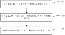
- the user equipment acquires a starting position of the third subframe.
- the third subframe is an authorized carrier subframe. Because the subframe of the authorized carrier is the same as the subframe of the unlicensed carrier, the bearer synchronization in the first subframe may be directly determined according to the starting position of the authorized carrier subframe. The position range of the OFDM symbol of the orthogonal frequency division multiplexing of the signal.
- the user equipment determines a location range of the OFDM symbol according to a starting position of the third subframe, a cyclic prefix CP of the OFDM symbol, and a number of cell reference signals CRS of the first subframe.
- the user equipment acquires the synchronization signal according to a location range of the OFDM symbol.
- the synchronization signal includes a coarse synchronization signal and a fine synchronization signal
- the coarse synchronization signal includes at least one of: a primary synchronization signal PSS and a secondary synchronization signal SSS
- the fine synchronization signal includes: a cell reference signal CRS.
- the user equipment performs synchronization according to the synchronization signal, where the first subframe and the second subframe are unlicensed carrier subframes.
- step 604 the coarse synchronization signal is specifically performed on the unlicensed carrier. Synchronization, fine synchronization is performed on the unlicensed carrier by detecting the cell reference signal CRS.
- the network device in the subframe of the unlicensed carrier, sends the first subframe carrying the synchronization signal to the user equipment by setting the synchronization signal in the first subframe, and the user equipment receives the first Synchronization signals are acquired in the subframes and synchronized, thereby realizing synchronization of data frames transmitted between devices in an unlicensed carrier.
- the method further includes:
- the user equipment detects a cell reference signal CRS of the second subframe.
- the user equipment acquires a starting position of the second subframe according to the cell reference signal CRS, where a starting position of the second subframe is that the user equipment receives the second subframe that is sent by the network device The location of the first OFDM symbol.
- the user equipment detects the CRS in the second subframe, and acquires the second subframe according to the CRS.
- the starting position to synchronize the transmission of data frames between devices throughout the unlicensed carrier may also be a complete subframe, and the start position of the entire data frame is the position of the first OFDM symbol of the first subframe determined in step 602.
- an embodiment of the present invention provides a network device, where the foregoing synchronization method is implemented, including:
- a setting unit 141 configured to set a synchronization signal in the first subframe
- the sending unit 142 is configured to send, to the user equipment, the first subframe or the first subframe and the second subframe, where the first subframe includes M orthogonal frequency division multiplexing OFDM symbols, where The two subframes include N OFDM symbols;
- the first subframe and the second subframe are unlicensed carrier subframes.
- the network device in a subframe of the unlicensed carrier, the network device sends the first subframe carrying the synchronization signal to the user equipment by setting a synchronization signal in the first subframe, so that the user equipment receives the first Synchronization signals are acquired in the subframes and synchronized, thereby realizing synchronization of data frames transmitted between devices in an unlicensed carrier.
- the setting unit 141 is configured to set the synchronization signal in a predetermined symbol of the first subframe.
- the first subframe includes four cell reference signals CRS;
- the setting unit 141 is specifically configured to set the synchronization signal in a third symbol in the first subframe.
- the first subframe includes one cell reference signal CRS port or two cell reference signal CRS ports;
- the setting unit 141 is specifically configured to set the synchronization signal in a second symbol in the first subframe.
- the first subframe does not include a cell reference signal CRS
- the setting unit 141 is specifically configured to set the synchronization signal in a first symbol in the first subframe.
- the first subframe includes two time slots.
- the setting unit 141 is specifically configured to set the synchronization signal in a last symbol or a second last symbol of a first time slot in the first subframe.
- the synchronization signal includes at least one of the following: a primary synchronization signal PSS and a secondary synchronization signal SSS.
- the sending unit 142 in this embodiment may be a transmitter of a network device.
- the setting unit 141 may be a separately set processor, or may be integrated in a processor of the network device, or may be stored in the memory of the base station in the form of program code, and is called by a processor of the network device. And the function of the above setting unit 141 is executed.
- the processor described herein may be a central processing unit (English name: Central Processing Unit, English abbreviation: CPU), or a specific integrated circuit (English name: Application Specific Integrated Circuit, English abbreviation: ASIC), or configured One or more integrated circuits embodying embodiments of the present invention
- an embodiment of the present invention provides a user equipment, which is used to implement the foregoing synchronization method, and includes:
- the receiving unit 151 is configured to receive a first subframe or the first subframe sent by the network device a frame and a second subframe, the first subframe includes M orthogonal frequency division multiplexing OFDM symbols, the second subframe includes N OFDM symbols, where M and N are positive integers, and M>N;
- a location determining unit 152 configured to determine a location range of an orthogonal frequency division multiplexing OFDM symbol carrying a synchronization signal in the first subframe received by the receiving unit 151;
- the obtaining unit 153 is configured to acquire the synchronization signal according to the location range of the OFDM symbol determined by the location determining unit 152;
- the synchronization unit 154 is configured to perform synchronization according to the synchronization signal acquired by the acquiring unit 153, where the first subframe and the second subframe are unlicensed carrier subframes.
- the network device in a subframe of the unlicensed carrier, sends the first subframe carrying the synchronization signal to the user equipment by setting a synchronization signal in the first subframe, and the first subframe of the user equipment is received. Synchronization signals are acquired in the frame and synchronized, thereby realizing synchronization of data frames transmitted between devices in an unlicensed carrier.
- the location determining unit 152 is specifically configured to acquire a starting position of the third subframe, according to a starting position of the third subframe, a cyclic prefix CP of the OFDM symbol, and the first sub
- the number of cell reference signals CRS of the frame determines a range of locations of the OFDM symbol; wherein the third subframe is an authorized carrier subframe.
- the user equipment further includes:
- the detecting unit 155 is configured to detect a cell reference signal CRS of the second subframe
- the location determining unit 152 is further configured to acquire a starting position of the second subframe according to the cell reference signal CRS detected by the detecting unit 155, where a starting position of the second subframe is the user
- the device receives a location of a first OFDM symbol of the second subframe sent by the network device.
- the synchronization signal includes at least one of the following: a primary synchronization signal PSS and a secondary synchronization signal SSS.
- the receiving unit 151 in this embodiment may be a receiver of the user equipment.
- the location determining unit 152 may be a separately set processor, or may be implemented in one processor of the user equipment, or may be stored in the memory of the user equipment in the form of program code, and processed by one of the user equipments.
- the device invokes and executes the functions of the above position determining unit 152.
- the obtaining unit 153 and the synchronization unit 154 The implementation of the detection unit 155 is similar to the location determination unit 152 and may be integrated with the location determination unit 152 or may be implemented independently.
- the processor described herein can be a central processing unit CPU, or a specific integrated circuit ASIC, or one or more integrated circuits configured to implement embodiments of the present invention.
- an embodiment of the present invention provides a network device for implementing the foregoing synchronization method, including: a processor 161, an interface circuit 162, a memory 163, and a bus 164; the processor 161 and the interface circuit 162.
- the memory 163 is connected through the bus 164 and completes communication with each other;
- the processor 161 herein may be a processor or a collective name of multiple processing elements.
- the processor may be a central processing unit CPU, or a specific integrated circuit ASIC, or one or more integrated circuits configured to implement embodiments of the present invention, such as one or more microprocessors (English full name) : digital singnal processor, English abbreviation: DSP), or one or more field programmable gate arrays (English full name: Field Programmable Gate Array, English abbreviation: FPGA).
- the memory 163 may be a storage device or a collective name of a plurality of storage elements, and is used to store executable program code or parameters, data, and the like required for the operation of the access network management device.
- the memory 163 may include a random access memory (English name: Random-Access Memory, English abbreviation: RAM), and may also include non-volatile memory (English name: non-volatile memory, English abbreviation: NVRAM), such as disk storage, flash memory. (Flash) and so on.
- the bus 164 can be an industry standard architecture (English name: Industry Standard Architecture, English abbreviation: ISA) bus, external device interconnection (English full name: Peripheral Component, English abbreviation: PCI) bus or extended industry standard architecture (English full name: Extended Industry Standard Architecture, English abbreviation: EISA) bus.
- the bus 164 can be divided into an address bus, a data bus, a control bus, and the like. For ease of representation, only one thick line is shown in Figure 16, but it does not mean that there is only one bus or one type of bus.
- the interface circuit 162 can be configured as a transmitter having a signal transmitting function.
- the processor 161 is configured to set a synchronization signal in the first subframe.
- the interface circuit 162 is configured to send the first subframe or the first subframe and the second subframe to a user equipment, where the first subframe includes M orthogonal frequency division multiplexing OFDM symbols, where The second subframe includes N OFDM symbols;
- the first subframe and the second subframe are unlicensed carrier subframes.
- the network device in a subframe of the unlicensed carrier, the network device sends the first subframe carrying the synchronization signal to the user equipment by setting a synchronization signal in the first subframe, so that the user equipment receives the first Synchronization signals are acquired in the subframes and synchronized, thereby realizing synchronization of data frames transmitted between devices in an unlicensed carrier.
- the processor is configured to set the synchronization signal in a predetermined symbol of the first subframe.
- the first subframe includes four cell reference signals CRS;
- the processor 161 is specifically configured to set the synchronization signal in a third symbol in the first subframe.
- the first subframe includes one cell reference signal CRS port or two cell reference signal CRS ports;
- the processor 161 is specifically configured to set the synchronization signal in a second symbol in the first subframe.
- the first subframe does not include a cell reference signal CRS
- the processor 161 is specifically configured to set the synchronization signal in a first symbol in the first subframe.
- the first subframe includes two time slots.
- the processor 161 is specifically configured to set the synchronization signal in a last symbol or a second last symbol of a first time slot in the first subframe.
- the synchronization signal includes at least one of the following: a primary synchronization signal PSS and a secondary synchronization signal SSS.
- an embodiment of the present invention provides a user equipment, which is used to implement
- the synchronization method includes: a processor 171, an interface circuit 172, a memory 173, and a bus 174; the processor 171, the interface circuit 172, and the memory 173 are connected through the bus 174 and complete communication with each other;
- the processor 171 herein may be a processor or a collective name of multiple processing elements.
- the processor may be a central processing unit CPU, or a specific integrated circuit ASIC, or one or more integrated circuits configured to implement embodiments of the present invention, such as one or more microprocessors (English full name) : digital singnal processor, English abbreviation: DSP), or one or more field programmable gate arrays (English full name: Field Programmable Gate Array, English abbreviation: FPGA).
- the memory 173 may be a storage device or a collective name of a plurality of storage elements, and is used to store executable program code or parameters, data, and the like required for the operation of the access network management device.
- the memory 173 may include a random access memory (English name: Random-Access Memory, English abbreviation: RAM), and may also include non-volatile memory (English name: non-volatile memory, English abbreviation: NVRAM), such as disk storage, flash memory. (Flash) and so on.
- the bus 174 can be an industry standard architecture (English name: Industry Standard Architecture, English abbreviation: ISA) bus, external device interconnection (English full name: Peripheral Component, English abbreviation: PCI) bus or extended industry standard architecture (English full name: Extended Industry Standard Architecture, English abbreviation: EISA) bus.
- the bus 174 can be divided into an address bus, a data bus, a control bus, and the like. For ease of representation, only one thick line is shown in Figure 17, but it does not mean that there is only one bus or one type of bus.
- the interface circuit 172 can be configured as a receiver having a signal receiving function.
- the interface circuit 172 is configured to receive the first subframe or the first subframe and the second subframe that are sent by the network device, where the first subframe includes M orthogonal frequency division multiplexing OFDM symbols, and the second The subframe includes N OFDM symbols, where M and N are positive integers, and M>N;
- the processor 171 is configured to determine a bearer synchronization in the first subframe received by the interface circuit. Orthogonal frequency division multiplexing OFDM symbol position range of the signal; acquiring the synchronization signal according to the location range of the OFDM symbol; synchronizing according to the synchronization signal, the first subframe and the second subframe are Unlicensed carrier subframe.
- the network device in a subframe of the unlicensed carrier, sends the first subframe carrying the synchronization signal to the user equipment by setting a synchronization signal in the first subframe, and the first subframe of the user equipment is received. Synchronization signals are acquired in the frame and synchronized, thereby realizing synchronization of data frames transmitted between devices in an unlicensed carrier.
- the processor 171 is specifically configured to acquire a starting position of the third subframe, according to a starting position of the third subframe, a cyclic prefix CP of the OFDM symbol, and the first subframe.
- the number of cell reference signals CRS determines the location range of the OFDM symbol
- the third subframe is an authorized carrier subframe.
- the processor 171 is further configured to detect a cell reference signal CRS of the second subframe, and acquire a start position of the second subframe according to the cell reference signal CRS, where the second subframe is The starting position is a location where the user equipment receives the first OFDM symbol of the second subframe sent by the network device.
- the synchronization signal includes at least one of the following: a primary synchronization signal PSS and a secondary synchronization signal SSS.
- a computer readable medium comprising computer readable instructions that, when executed, perform the following operations: 101 to 102, 201 to 203, 301 to 303, 401 performing the methods in the above embodiments.
- the operation to 403, 501 to 503 or 601 to 604.
- a computer program product including the computer readable medium described above.
- the signaling mentioned in the text includes, but is not limited to, an indication, an information, a signal, or a message, and is not limited herein.
- the size of the sequence numbers of the above processes does not mean the order of execution, and the order of execution of each process should be determined by its function and internal logic, and should not be taken to the embodiments of the present invention.
- the implementation process constitutes any limitation.
- the disclosed systems, devices, and methods may be implemented in other manners.
- the device embodiments described above are merely illustrative.
- the division of the unit is only a logical function division.
- there may be another division manner for example, multiple units or components may be combined or Can be integrated into another system, or some features can be ignored or not executed.
- the mutual coupling or direct coupling or communication connection shown or discussed may be an indirect coupling or communication connection through some interface, device or unit, and may be in an electrical, mechanical or other form.
- the units described as separate components may or may not be physically separated, and the components displayed as units may or may not be physical units, that is, may be located in one place, or may be distributed to multiple network units. Some or all of the units may be selected according to actual needs to achieve the purpose of the solution of the embodiment.
- each functional unit in each embodiment of the present invention may be integrated into one processing unit, or each unit may exist physically separately, or two or more units may be integrated into one unit.
- the function is implemented in the form of a software functional unit and sold as a separate product When sold or used, it can be stored on a computer readable storage medium.
- the technical solution of the present invention which is essential or contributes to the prior art, or a part of the technical solution, may be embodied in the form of a software product, which is stored in a storage medium, including
- the instructions are used to cause a computer device (which may be a personal computer, server, or network device, etc.) to perform all or part of the steps of the methods described in various embodiments of the present invention.
- the foregoing storage medium includes: a U disk, a mobile hard disk, a read-only memory (ROM), a random access memory (RAM), a magnetic disk, or an optical disk, and the like. .
Abstract
Description
Claims (30)
- 一种同步方法,其特征在于,包括:网络设备在第一子帧中设置同步信号;所述网络设备向用户设备发送所述第一子帧或所述第一子帧和第二子帧,所述第一子帧包括M个正交频分复用OFDM符号,所述第二子帧包括N个OFDM符号;其中M和N为正整数,且M>N,所述第一子帧和所述第二子帧为非授权载波子帧。
- 根据权利要求1所述的方法,其特征在于,所述网络设备在第一子帧中设置同步信号,包括:所述网络设备在所述第一子帧的预定符号中设置所述同步信号。
- 根据权利要求2所述的方法,其特征在于,所述第一子帧包括四个小区参考信号CRS;所述网络设备在第一子帧中设置同步信号,包括:所述网络设备在所述第一子帧中的第三个符号中设置所述同步信号。
- 根据权利要求2所述的方法,其特征在于,所述第一子帧包括一个小区参考信号CRS端口或者两个小区参考信号CRS端口;所述网络设备在第一子帧中设置同步信号,包括:所述网络设备在所述第一子帧中的第二个符号中设置所述同步信号。
- 根据权利要求2所述的方法,其特征在于,所述第一子帧不包括小区参考信号CRS;所述网络设备在第一子帧中设置同步信号,包括:所述网络设备在所述第一子帧中的第一个符号中设置所述同步信号。
- 根据权利要求2所述的方法,其特征在于,所述第一子帧包括两个时隙,所述网络设备在第一子帧中设置同步信号,包括:所述网络设备在所述第一子帧中第一个时隙的倒数第一个符号或倒数第 二个符号设置所述同步信号。
- 根据权利要求1-6任一项所述的方法,其特征在于,所述同步信号至少包括以下各项中的一个:主同步信号PSS和辅同步信号SSS。
- 一种同步方法,其特征在于,包括:用户设备接收网络设备发送的第一子帧或所述第一子帧和第二子帧,所述第一子帧包括M个正交频分复用OFDM符号,所述第二子帧包括N个OFDM符号,其中M和N为正整数,且M>N;所述用户设备确定所述第一子帧中承载同步信号的正交频分复用OFDM符号的位置范围;所述用户设备根据所述OFDM符号的位置范围获取所述同步信号;所述用户设备根据所述同步信号进行同步,所述第一子帧和所述第二子帧为非授权载波子帧。
- 根据权利要求8所述的方法,其特征在于,所述用户设备确定所述第一子帧中承载同步信号的正交频分复用OFDM符号的位置范围,包括:所述用户设备获取第三子帧的起始位置;所述用户设备根据所述第三子帧的起始位置、所述OFDM符号的循环前缀CP以及所述第一子帧的小区参考信号CRS的数目确定所述OFDM符号的位置范围,其中,所述第三子帧为授权载波子帧。
- 根据权利要求9所述的方法,其特征在于,所述方法还包括:所述用户设备检测所述第二子帧的小区参考信号CRS;所述用户设备根据所述小区参考信号CRS获取所述第二子帧的起始位置,所述第二子帧的起始位置为所述用户设备接收所述网络设备发送的所述第二子帧的第一个OFDM符号的位置。
- 根据权利要求8-10任一项所述的方法,其特征在于,所述同步信号至少包括以下各项中的一个:主同步信号PSS和辅同步信号SSS。
- 一种网络设备,其特征在于,包括:设置单元,用于在第一子帧中设置同步信号;发送单元,用于向用户设备发送所述第一子帧或所述第一子帧和第二子帧,所述第一子帧包括M个正交频分复用OFDM符号,所述第二子帧包括N个OFDM符号;其中M和N为正整数,且M>N,所述第一子帧和所述第二子帧为非授权载波子帧。
- 根据权利要求12所述的网络设备,其特征在于,所述设置单元,用于在所述第一子帧的预定符号中设置所述同步信号。
- 根据权利要求13所述的网络设备,其特征在于,所述第一子帧包括四个小区参考信号CRS;所述设置单元,具体用于在所述第一子帧中的第三个符号中设置所述同步信号。
- 根据权利要求13所述的网络设备,其特征在于,所述第一子帧包括一个小区参考信号CRS端口或者两个小区参考信号CRS端口;所述设置单元,具体用于在所述第一子帧中的第二个符号中设置所述同步信号。
- 根据权利要求13所述的网络设备,其特征在于,所述第一子帧不包括小区参考信号CRS;所述设置单元,具体用于在所述第一子帧中的第一个符号中设置所述同步信号。
- 根据权利要求13所述的网络设备,其特征在于,所述第一子帧包括两个时隙,所述设置单元,具体用于在所述第一子帧中第一个时隙的倒数第一个符号或倒数第二个符号设置所述同步信号。
- 一种用户设备,其特征在于,包括:接收单元,用于接收网络设备发送的第一子帧或所述第一子帧和第二子帧,所述第一子帧包括M个正交频分复用OFDM符号,所述第 二子帧包括N个OFDM符号,其中M和N为正整数,且M>N;位置确定单元,用于确定所述接收单元接收的第一子帧中承载同步信号的正交频分复用OFDM符号的位置范围;获取单元,用于根据所述位置确定单元确定的所述OFDM符号的位置范围获取所述同步信号;同步单元,用于根据所述获取单元获取的所述同步信号进行同步,所述第一子帧和所述第二子帧为非授权载波子帧。
- 根据权利要求18所述的用户设备,其特征在于,所述位置确定单元,具体用于获取第三子帧的起始位置;根据所述第三子帧的起始位置、所述OFDM符号的循环前缀CP以及所述第一子帧的小区参考信号CRS的数目确定所述OFDM符号的位置范围,其中,所述第三子帧为授权载波子帧。
- 根据权利要求18所述的用户设备,其特征在于,所述用户设备还包括:检测单元,用于检测所述第二子帧的小区参考信号CRS;所述位置确定单元,还用于根据所述检测单元检测的所述小区参考信号CRS获取所述第二子帧的起始位置,所述第二子帧的起始位置为所述用户设备接收所述网络设备发送的所述第二子帧的第一个OFDM符号的位置。
- 一种网络设备,其特征在于,包括:处理器、接口电路、存储器和总线;所述处理器、接口电路、存储器通过所述总线连接并完成相互间的通信;其中,所述处理器用于在第一子帧中设置同步信号;所述接口电路,用于向用户设备发送所述第一子帧或所述第一子帧和第二子帧,所述第一子帧包括M个正交频分复用OFDM符号,所述第二子帧包括N个OFDM符号;其中M和N为正整数,且M>N,所述第一子帧和所述第二子帧为非授权载波子帧。
- 根据权利要求21所述的网络设备,其特征在于,所述处理 器,用于在所述第一子帧的预定符号中设置所述同步信号。
- 根据权利要求22所述的网络设备,其特征在于,所述第一子帧包括四个小区参考信号CRS;所述处理器,具体用于在所述第一子帧中的第三个符号中设置所述同步信号。
- 根据权利要求22所述的网络设备,其特征在于,所述第一子帧包括一个小区参考信号CRS端口或者两个小区参考信号CRS端口;所述处理器,具体用于在所述第一子帧中的第二个符号中设置所述同步信号。
- 根据权利要求22所述的网络设备,其特征在于,所述第一子帧不包括小区参考信号CRS;所述处理器,具体用于在所述第一子帧中的第一个符号中设置所述同步信号。
- 根据权利要求22所述的网络设备,其特征在于,所述第一子帧包括两个时隙,所述处理器,具体用于在所述第一子帧中第一个时隙的倒数第一个符号或倒数第二个符号设置所述同步信号。
- 一种用户设备,其特征在于,包括:处理器、接口电路、存储器和总线;所述处理器、接口电路、存储器通过所述总线连接并完成相互间的通信;接口电路,用于接收网络设备发送的第一子帧或所述第一子帧和第二子帧,所述第一子帧包括M个正交频分复用OFDM符号,所述第二子帧包括N个OFDM符号,其中M和N为正整数,且M>N;处理器,用于确定所述接口电路接收的第一子帧中承载同步信号的正交频分复用OFDM符号的位置范围;根据所述OFDM符号的位置范围获取所述同步信号;根据所述同步信号进行同步,所述第一子帧和所述第二子帧为非授权载波子帧。
- 根据权利要求27所述的用户设备,其特征在于,所述处理 器,具体用于获取第三子帧的起始位置;根据所述第三子帧的起始位置、所述OFDM符号的循环前缀CP以及所述第一子帧的小区参考信号CRS的数目确定所述OFDM符号的位置范围,其中,所述第三子帧为授权载波子帧。
- 根据权利要求27所述的用户设备,其特征在于,所述处理器还用于检测所述第二子帧的小区参考信号CRS;根据所述小区参考信号CRS获取所述第二子帧的起始位置,所述第二子帧的起始位置为所述用户设备接收所述网络设备发送的所述第二子帧的第一个OFDM符号的位置。
- 一种通信系统,其特征在于,包括权利要求12-17任一项所述的网络设备和权利要求18-20任一项所述的用户设备;或者,包括权利要求21-26任一项所述的网络设备和权利要求27-29任一项所述的用户设备。
Priority Applications (5)
| Application Number | Priority Date | Filing Date | Title |
|---|---|---|---|
| EP15878373.8A EP3242512B1 (en) | 2015-01-21 | 2015-01-21 | Synchronization method, apparatus and system |
| CN201580066976.1A CN107005959B (zh) | 2015-01-21 | 2015-01-21 | 一种同步方法、装置及系统 |
| PCT/CN2015/071221 WO2016115695A1 (zh) | 2015-01-21 | 2015-01-21 | 一种同步方法、装置及系统 |
| KR1020177022998A KR102201789B1 (ko) | 2015-01-21 | 2015-01-21 | 동기화 방법, 장치 및 시스템 |
| US15/545,471 US10567206B2 (en) | 2015-01-21 | 2015-01-21 | Synchronization method, apparatus, and system |
Applications Claiming Priority (1)
| Application Number | Priority Date | Filing Date | Title |
|---|---|---|---|
| PCT/CN2015/071221 WO2016115695A1 (zh) | 2015-01-21 | 2015-01-21 | 一种同步方法、装置及系统 |
Publications (1)
| Publication Number | Publication Date |
|---|---|
| WO2016115695A1 true WO2016115695A1 (zh) | 2016-07-28 |
Family
ID=56416280
Family Applications (1)
| Application Number | Title | Priority Date | Filing Date |
|---|---|---|---|
| PCT/CN2015/071221 WO2016115695A1 (zh) | 2015-01-21 | 2015-01-21 | 一种同步方法、装置及系统 |
Country Status (5)
| Country | Link |
|---|---|
| US (1) | US10567206B2 (zh) |
| EP (1) | EP3242512B1 (zh) |
| KR (1) | KR102201789B1 (zh) |
| CN (1) | CN107005959B (zh) |
| WO (1) | WO2016115695A1 (zh) |
Families Citing this family (4)
| Publication number | Priority date | Publication date | Assignee | Title |
|---|---|---|---|---|
| CN109391578B (zh) * | 2017-08-11 | 2022-07-22 | 华为技术有限公司 | 信号发送方法、信号接收方法、终端设备及网络设备 |
| US10743371B2 (en) * | 2018-01-29 | 2020-08-11 | Apple Inc. | Syncrhonization signals for multefire narrowband internet-of-things (MF NB-IoT) operation in unlicensed spectrum |
| WO2020137072A1 (ja) * | 2018-12-28 | 2020-07-02 | パナソニック インテレクチュアル プロパティ コーポレーション オブ アメリカ | 送信装置、受信装置、送信方法及び受信方法 |
| CN117320046B (zh) * | 2023-11-28 | 2024-03-01 | 深圳市鼎阳科技股份有限公司 | Crs搜索方法、lte时间对齐误差测定方法和用户设备 |
Citations (4)
| Publication number | Priority date | Publication date | Assignee | Title |
|---|---|---|---|---|
| CN102239649A (zh) * | 2008-12-02 | 2011-11-09 | Lg电子株式会社 | 在下行链路多输入多输出系统中发送参考信号的方法 |
| CN102396198A (zh) * | 2009-03-17 | 2012-03-28 | 三星电子株式会社 | 用于在多流传输中映射导频信号的方法和系统 |
| CN103686987A (zh) * | 2012-09-26 | 2014-03-26 | 北京三星通信技术研究有限公司 | 发送和接收同步信道、广播信道的方法和设备 |
| CN104009784A (zh) * | 2008-08-05 | 2014-08-27 | Lg电子株式会社 | 用于下行多输入多输出系统的基准信号传输方法 |
Family Cites Families (4)
| Publication number | Priority date | Publication date | Assignee | Title |
|---|---|---|---|---|
| WO2012148236A2 (ko) * | 2011-04-28 | 2012-11-01 | 엘지전자 주식회사 | 반송파 집성 시스템에서 동기화 신호 전송 방법 및 장치 |
| CN104411279B (zh) * | 2012-06-29 | 2016-11-09 | 宝洁公司 | 用于制造可重复扣紧的制品的方法 |
| CN103686978A (zh) * | 2013-12-24 | 2014-03-26 | 深圳市双赢伟业科技股份有限公司 | 无线终端设备发射功率控制方法 |
| US9986373B2 (en) * | 2015-01-12 | 2018-05-29 | Intel Corporation | LTE-A systems and method of DRS based positioning |
-
2015
- 2015-01-21 EP EP15878373.8A patent/EP3242512B1/en active Active
- 2015-01-21 WO PCT/CN2015/071221 patent/WO2016115695A1/zh active Application Filing
- 2015-01-21 CN CN201580066976.1A patent/CN107005959B/zh active Active
- 2015-01-21 KR KR1020177022998A patent/KR102201789B1/ko active IP Right Grant
- 2015-01-21 US US15/545,471 patent/US10567206B2/en active Active
Patent Citations (4)
| Publication number | Priority date | Publication date | Assignee | Title |
|---|---|---|---|---|
| CN104009784A (zh) * | 2008-08-05 | 2014-08-27 | Lg电子株式会社 | 用于下行多输入多输出系统的基准信号传输方法 |
| CN102239649A (zh) * | 2008-12-02 | 2011-11-09 | Lg电子株式会社 | 在下行链路多输入多输出系统中发送参考信号的方法 |
| CN102396198A (zh) * | 2009-03-17 | 2012-03-28 | 三星电子株式会社 | 用于在多流传输中映射导频信号的方法和系统 |
| CN103686987A (zh) * | 2012-09-26 | 2014-03-26 | 北京三星通信技术研究有限公司 | 发送和接收同步信道、广播信道的方法和设备 |
Also Published As
| Publication number | Publication date |
|---|---|
| EP3242512B1 (en) | 2020-11-25 |
| EP3242512A1 (en) | 2017-11-08 |
| KR102201789B1 (ko) | 2021-01-11 |
| CN107005959A (zh) | 2017-08-01 |
| CN107005959B (zh) | 2020-04-21 |
| EP3242512A4 (en) | 2017-11-29 |
| US20180013601A1 (en) | 2018-01-11 |
| US10567206B2 (en) | 2020-02-18 |
| KR20170106420A (ko) | 2017-09-20 |
Similar Documents
| Publication | Publication Date | Title |
|---|---|---|
| US20210014817A1 (en) | Synchronization method, user equipment, and base station | |
| WO2018228433A1 (zh) | 一种公共下行控制信道的传输方法和相关设备 | |
| TWI737844B (zh) | 傳輸參考信號的方法和通訊設備 | |
| RU2625816C1 (ru) | Передатчик, приемник и способы для передачи/приема сигналов синхронизации | |
| WO2018018417A1 (zh) | 信息传输方法和信息传输设备 | |
| JP2020510349A5 (zh) | ||
| WO2016070704A1 (zh) | 一种在非授权频段上的数据传输方法及装置 | |
| TWI759560B (zh) | 傳輸訊息的方法和設備 | |
| WO2018028490A1 (zh) | 信息传输方法、终端及网络设备 | |
| WO2017128883A1 (zh) | 一种导频信号发送、信道估计方法及设备 | |
| WO2016115695A1 (zh) | 一种同步方法、装置及系统 | |
| TW201838466A (zh) | 處理量測間距的裝置及方法 | |
| TWI746549B (zh) | 訊號傳輸的方法、網路設備和終端設備 | |
| CN114424666B (zh) | 一种通信方法及装置 | |
| WO2015139555A1 (zh) | 一种信号发送、接收方法及装置 | |
| WO2020143432A1 (zh) | 一种同步广播信息发送、检测方法及装置 | |
| WO2016161985A1 (zh) | 信号处理方法、发送机、接收机及信号处理系统 | |
| WO2018177216A1 (zh) | 传输信号的方法和装置 | |
| WO2018028343A1 (zh) | 传输信号的方法和装置 | |
| WO2022028171A1 (zh) | 定位方法、装置、终端及基站 | |
| WO2020156024A1 (zh) | 用于传输下行控制信道的方法、终端设备和网络设备 | |
| WO2020029837A1 (zh) | 一种同步广播信息的发送、检测方法及装置 | |
| WO2016019529A1 (zh) | 同步通信的方法和通信节点 | |
| WO2017167001A1 (zh) | 资源调度方法、终端设备及系统 | |
| WO2018014297A1 (zh) | 信息传输装置、方法以及无线通信系统 |
Legal Events
| Date | Code | Title | Description |
|---|---|---|---|
| 121 | Ep: the epo has been informed by wipo that ep was designated in this application |
Ref document number: 15878373 Country of ref document: EP Kind code of ref document: A1 |
|
| WWE | Wipo information: entry into national phase |
Ref document number: 15545471 Country of ref document: US |
|
| NENP | Non-entry into the national phase |
Ref country code: DE |
|
| REEP | Request for entry into the european phase |
Ref document number: 2015878373 Country of ref document: EP |
|
| ENP | Entry into the national phase |
Ref document number: 20177022998 Country of ref document: KR Kind code of ref document: A |