WO2016110912A1 - 遠隔操作装置 - Google Patents
遠隔操作装置 Download PDFInfo
- Publication number
- WO2016110912A1 WO2016110912A1 PCT/JP2015/006335 JP2015006335W WO2016110912A1 WO 2016110912 A1 WO2016110912 A1 WO 2016110912A1 JP 2015006335 W JP2015006335 W JP 2015006335W WO 2016110912 A1 WO2016110912 A1 WO 2016110912A1
- Authority
- WO
- WIPO (PCT)
- Prior art keywords
- remote control
- control device
- recess
- communication terminal
- members
- Prior art date
- Legal status (The legal status is an assumption and is not a legal conclusion. Google has not performed a legal analysis and makes no representation as to the accuracy of the status listed.)
- Ceased
Links
Images

Classifications
-
- B—PERFORMING OPERATIONS; TRANSPORTING
- B60—VEHICLES IN GENERAL
- B60R—VEHICLES, VEHICLE FITTINGS, OR VEHICLE PARTS, NOT OTHERWISE PROVIDED FOR
- B60R16/00—Electric or fluid circuits specially adapted for vehicles and not otherwise provided for; Arrangement of elements of electric or fluid circuits specially adapted for vehicles and not otherwise provided for
- B60R16/02—Electric or fluid circuits specially adapted for vehicles and not otherwise provided for; Arrangement of elements of electric or fluid circuits specially adapted for vehicles and not otherwise provided for electric constitutive elements
-
- H—ELECTRICITY
- H04—ELECTRIC COMMUNICATION TECHNIQUE
- H04Q—SELECTING
- H04Q9/00—Arrangements in telecontrol or telemetry systems for selectively calling a substation from a main station, in which substation desired apparatus is selected for applying a control signal thereto or for obtaining measured values therefrom
Definitions
- the present disclosure relates to a remote operation device for remotely operating a mobile communication terminal in a vehicle.
- the operation device disclosed in Patent Document 1 captures a touch panel screen of a mobile communication terminal, and displays the image superimposed on the touch panel screen of the operation device. Then, when there is an operation input to the touch panel of the operation device, the operation device calculates a position on the touch panel of the mobile communication terminal corresponding to the operation position, and transmits the position information to the mobile communication terminal. Thereby, the operation of the mobile communication terminal can be performed by an operation input to the operation device.
- a technology has been considered in which a vehicle device such as a navigation device is connected to a mobile communication terminal such as a smartphone so that communication can be performed, and an application executed on the smartphone is output from a display unit of the navigation device.
- a remote operation device for remotely operating a smartphone which is an execution subject of an application is also being advanced.
- the remote operation device can be easily operated without visual inspection.
- An object of the present disclosure is to provide a remote operation device for remotely operating a mobile communication terminal in a vehicle, which can be easily operated without visually observing the remote operation device. .
- the remote control device remotely controls the mobile communication terminal in the vehicle.
- the remote operation device includes a hollow portion that is recessed in a spherical shape, and a plurality of operation members provided in the recessed portion. As the plurality of operation members are provided on the outer peripheral side of the recessed portion, the protruding amount from the surface of the recessed portion is larger.
- the user can easily operate each operation member by moving the finger inserted into the recess so as to be along the surface of the recess. Further, the user can recognize the position of the operation member, in other words, which operation member is the operation member, based on the protruding amount of the operation member that the finger contacts. Therefore, the user can easily operate the remote control device without viewing it.
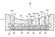
- Sectional drawing which shows schematically the structural example of the remote control apparatus which concerns on one Embodiment Top view of remote control device Sectional drawing which expands and shows a part of remote control device The figure which shows the example of attachment of the remote control apparatus with respect to a steering wheel The figure which shows an example of the use condition of a remote control device
- the remote control device 10 illustrated in FIGS. 1 and 2 has a thin disk shape as a whole, and includes a recess 12 on one end surface of the device main body 11 constituting the outer shell.
- the recess 12 is recessed in a smooth spherical shape.
- a plurality of operation members are provided in the recess 12.
- five operation members 13, 14, 15, 16, and 17 are provided.
- Each of the operation members 13, 14, 15, 16, and 17 has operation surface portions 13 a, 14 a, 15 a, 16 a, and 17 a at end portions that protrude from the surface of the recess portion 12.
- the operation members 13, 14, 15, 16, and 17 are each pressed in the direction of arrow A when the operation surface portions 13 a, 14 a, 15 a, 16 a, and 17 a are pushed in by a user's finger.
- a control board 21 for controlling the overall operation of the remote operation device 10 is provided inside the device main body 11.
- a plurality of tact switches 22 corresponding to the operation members 13, 14, 15, 16, and 17 are mounted on the control board 21.
- the tact switch 22 corresponding to the operated operation member is turned on.
- a wireless communication module 23 is mounted on the control board 21.
- the wireless communication module 23 is an example of a wireless communication unit, can establish a wireless communication line with a mobile communication terminal (not shown) brought into the vehicle, and can perform wireless communication between the remote control device 10 and the mobile communication terminal. Connect to.
- Bluetooth communication Bluetooth: registered trademark
- BLE communication BLE: Bluetooth Low Energy
- the wireless communication standards that can be adopted in the present disclosure are not limited to these.
- a metal plate 24 is embedded in the apparatus main body 11. The metal plate 24 is provided at the end on the opposite side to the recess 12.
- the operation member 13 is provided at the center of the recess 12, in other words, at the bottom.
- the operation member 13 is provided in a straight line shape along the radial direction of the recess 12 and is provided as an enter key for confirming the operation content for the mobile communication terminal.
- the operation members 14 and 15 are provided on the outer peripheral side of the operation member 13.
- the operation member 14 is provided as a back key for returning the operation content input to the mobile communication terminal to the previous operation content.
- the operation member 15 is provided as a home key for shifting the display screen of the mobile communication terminal to the home screen.
- the operating member 16 is provided on the outer peripheral side of the operating members 14 and 15 so as to be accommodated in the notches 14b and 15b.
- the operation member 16 is provided as a function key for executing a predetermined function provided in the mobile communication terminal.
- the function of the mobile communication terminal assigned to the operation member 16 can be changed and set as appropriate.
- the operation member 17 is provided on the outer peripheral side of the operation member 16. In this case, the operation member 17 is provided in an annular shape along the outer peripheral portion of the recess 12 and is provided as a direction key for inputting an operation direction to the mobile communication terminal.
- the mobile communication terminal scrolls the display screen up, down, left, and right, for example, based on the direction information input through the operation of the operation member 17.
- the operation members 13, 14, 15, 16, and 17 have a larger amount of protrusion from the surface of the depression 12 as they are provided on the outer peripheral side of the depression 12.
- the protruding amount of the operating member 13 provided at the center of the recessed portion 12 is the smallest, and the protruding amount of the operating member 17 provided on the outer peripheral portion of the recessed portion 12 is the largest. That is, the protruding amounts 13p, 14p, 15p, 16p, and 17p of the operation members 13, 14, 15, 16, and 17 have a relationship of 13p ⁇ 14p (15p) ⁇ 16p ⁇ 17p.
- the operating members 14 and 15 are arranged in parallel between the operating member 13 and the operating member 16 in the recess 12. Therefore, the protruding amounts 14p and 15p of the operation members 14 and 15 are equal. However, the protrusion amounts 14p and 15p of the operation members 14 and 15 may be different.
- the operation surface portions 14 a, 15 a, 16 a, and 17 a of the operation members 14, 15, 16, and 17 provided around the operation member 13 all go from the center side of the recess portion 12 to the outer peripheral side of the recess portion 12.
- the protrusion amount from the surface of the hollow part 12 is so large that it is. That is, all the operation surface portions 14a, 15a, 16a, and 17a are inclined so as to rise from the center side toward the outer peripheral side.
- the normal directions of the operation surface portions 14 a, 15 a, 16 a, and 17 a intersect with the axial direction of the apparatus main body 11, respectively. Note that the operation surface portion 13 a of the operation member 13 is not inclined, and the normal direction thereof coincides with the axial direction of the apparatus main body portion 11.
- the remote control device 10 can be attached to and detached from an attachment portion 31 provided on the steering wheel 100 of the vehicle. That is, the attachment portion 31 includes a receiving portion 32 formed in a dish shape and a belt portion 33 extending from the receiving portion 32. A magnet (not shown) is embedded in the receiving portion 32. The attachment portion 31 is detachably attached to the steering wheel 100 by winding the belt portion 33 around the steering wheel 100.
- the remote control device 10 is disposed in the receiving portion 32, the metal plate 24 in the remote operation device 10 is magnetically attracted by the magnet in the receiving portion 32.
- the remote control device 10 is detachably fixed to the attachment portion 31. Further, the remote control device 10 is fixed to the attachment portion 31 by the magnetic action as described above. Therefore, the user can remove the remote control device 10 from the attachment portion 31 relatively easily.
- the attachment position of the attachment portion 31 with respect to the steering wheel 100 in other words, the attachment position of the remote control device 10 is set within a range where the user's finger holding the steering wheel 100 can reach without difficulty. It is preferable to do.
Landscapes
- Engineering & Computer Science (AREA)
- Mechanical Engineering (AREA)
- Computer Networks & Wireless Communication (AREA)
- Selective Calling Equipment (AREA)
- Fittings On The Vehicle Exterior For Carrying Loads, And Devices For Holding Or Mounting Articles (AREA)
Abstract
遠隔操作装置は、車両内において携帯通信端末を遠隔操作する。遠隔操作装置は、球面状に窪む窪み部(12)と、窪み部に設けられた複数の操作部材(13、14、15、16、17)と、を備える。複数の操作部材は、窪み部の外周側に設けられるものほど窪み部の表面からの突出量が大きくなっている。遠隔操作装置は、目視しなくとも容易に操作できる。
Description
本出願は、当該開示内容が参照によって本出願に組み込まれた、2015年1月7日に出願された日本特許出願2015-001495号を基にしている。
本開示は、車両内において携帯通信端末を遠隔操作するための遠隔操作装置に関する。
携帯通信端末を遠隔操作する操作装置に関する技術が考えられている。例えば特許文献1に開示されている操作装置は、携帯通信端末のタッチパネル画面を撮像し、その画像を操作装置のタッチパネル画面に重ねて表示する。そして、操作装置は、操作装置のタッチパネルへの操作入力があると、その操作位置に対応する携帯通信端末のタッチパネル上の位置を算出し、その位置情報を携帯通信端末に送信する。これにより、操作装置への操作入力により携帯通信端末の操作が可能となっている。
近年では、例えばナビゲーション装置などの車両用装置と例えばスマートフォンなどの携帯通信端末とを通信可能に接続し、スマートフォンにおいて実行するアプリケーションの出力をナビゲーション装置の表示部から行う技術が考えられている。そして、この技術の進展に伴い、アプリケーションの実行主体であるスマートフォンを遠隔操作するための遠隔操作装置の開発も進められている。特に車両内でスマートフォンを遠隔操作する遠隔操作装置においては、当該遠隔操作装置を目視しなくとも容易に操作可能とすることが求められる。
本開示は、車両内において携帯通信端末を遠隔操作するための遠隔操作装置であって、当該遠隔操作装置を目視しなくとも容易に操作することができる遠隔操作装置を提供することを目的とする。
本開示に係る遠隔操作装置は、車両内において携帯通信端末を遠隔操作する。遠隔操作装置は、球面状に窪む窪み部と、窪み部に設けられた複数の操作部材と、を備える。複数の操作部材は、窪み部の外周側に設けられるものほど窪み部の表面からの突出量が大きい。
この構成によれば、ユーザは、窪み部に挿入した指を当該窪み部の表面に沿わせるようにして移動させることにより、各操作部材を容易に操作することができる。また、ユーザは、指が接触した操作部材の突出量に基づいて、その操作部材の位置、換言すれば、その操作部材がどの操作部材であるのかを認識することができる。従って、ユーザは、遠隔操作装置を目視しなくとも容易に操作することができる。
本開示についての上記目的およびその他の目的、特徴や利点は、添付の図面を参照しながら下記の詳細な記述により、より明確になる。
一実施形態に係る遠隔操作装置の構成例を概略的に示す断面図
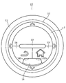
遠隔操作装置の平面図
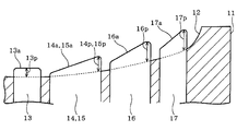
遠隔操作装置の一部を拡大して示す断面図
ステアリングホイールに対する遠隔操作装置の取り付け例を示す図
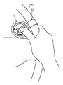
遠隔操作装置の使用状態の一例を示す図
以下、遠隔操作装置に係る一実施形態について図面を参照しながら説明する。図1および図2に例示する遠隔操作装置10は、全体として薄い円板状をなしており、その外殻を構成する装置本体部11の一端面に窪み部12を備える。窪み部12は、滑らかな球面状に窪んでいる。窪み部12内には、複数の操作部材が設けられている。本実施形態では、5つの操作部材13、14、15、16、17が設けられている。操作部材13、14、15、16、17は、何れも、窪み部12の表面から突出する端部に操作面部13a、14a、15a、16a、17aを有する。操作部材13、14、15、16、17は、ユーザの指により操作面部13a、14a、15a、16a、17aが押し込まれることで、それぞれ矢印A方向に押圧操作されるようになっている。
装置本体部11の内部には、遠隔操作装置10の動作全般を制御する制御基板21が設けられている。制御基板21には、操作部材13、14、15、16、17に対応する複数のタクトスイッチ22が実装されている。ユーザにより各操作部材13、14、15、16、17が押圧操作されると、その操作された操作部材に対応するタクトスイッチ22がオンされる。また、制御基板21には、無線通信モジュール23が実装されている。無線通信モジュール23は、無線通信部の一例であり、車両内に持ち込まれた図示しない携帯通信端末との間に無線の通信回線を確立し、遠隔操作装置10と携帯通信端末とを無線通信可能に接続する。
なお、無線通信規格としては、例えば、近距離無線通信の一例であるBluetooth通信(Bluetooth:登録商標)、より低い電力での利用が可能なBLE通信(BLE:Bluetooth Low Energy)などが考えられる。但し、本開示で採用できる無線通信規格は、これらに限られない。また、装置本体部11の内部には、金属板24が埋め込まれている。金属板24は、窪み部12とは反対側の端部に設けられている。
図2に例示するように、操作部材13は、窪み部12の中心部、換言すれば最底部に設けられている。この場合、操作部材13は、窪み部12の径方向に沿う直線状に設けられており、携帯通信端末に対する操作内容を確定するためのエンターキーとして備えられている。操作部材14、15は、操作部材13の外周側に設けられている。この場合、操作部材14は、携帯通信端末に入力した操作内容を1つ前の操作内容に戻すためのバックキーとして備えられている。また、操作部材15は、携帯通信端末の表示画面をホーム画面に移行させるためのホームキーとして備えられている。操作部材14、15は、操作部材13と操作部材16との間を二分するようにして設けられており、且つ、操作部材13の中心部と操作部材16の中心部とを結ぶ線を基準として線対称となるように設けられている。また、操作部材14、15には、それぞれ切欠き部14b、15bが設けられており、これら切欠き部14b、15bが隣接した構成となっている。
操作部材16は、操作部材14、15の外周側において、切欠き部14b、15bに収容されるようにして設けられている。この場合、操作部材16は、携帯通信端末が備える所定の機能を実行させるためのファンクションキーとして備えられている。なお、操作部材16に割り当てる携帯通信端末の機能は、適宜変更して設定することができる。操作部材17は、操作部材16の外周側に設けられている。この場合、操作部材17は、窪み部12の外周部に沿う円環状に設けられており、携帯通信端末に操作方向を入力するための方向キーとして備えられている。携帯通信端末は、この操作部材17の操作を介して入力される方向情報に基づいて、例えば表示画面を上下左右にスクロールさせる。
図3にも例示するように、操作部材13、14、15、16、17は、窪み部12の外周側に設けられるものほど窪み部12の表面からの突出量が大きくなっている。この場合、窪み部12の中心部に設けられる操作部材13の突出量が最も小さく、窪み部12の外周部に設けられる操作部材17の突出量が最も大きくなっている。即ち、各操作部材13、14、15、16、17の突出量13p、14p、15p、16p、17pは、13p<14p(15p)<16p<17pの関係となっている。なお、操作部材14、15は、窪み部12内において操作部材13と操作部材16との間に並列的に配置されている。従って、操作部材14、15の突出量14p、15pは等しくなっている。但し、操作部材14、15の突出量14p、15pを異ならせてもよい。
また、操作部材13の周囲に設けられる各操作部材14、15、16、17の操作面部14a、15a、16a、17aは、何れも、窪み部12の中心側から窪み部12の外周側に向かうほど窪み部12の表面からの突出量が大きくなっている。即ち、各操作面部14a、15a、16a、17aは、何れも、中心側から外周側に向かって上昇するように傾斜している。また、各操作面部14a、15a、16a、17aの法線方向は、それぞれ装置本体部11の軸方向と交わるようになっている。なお、操作部材13の操作面部13aは、傾斜しておらず、その法線方向が装置本体部11の軸方向と一致している。
図4に例示するように、遠隔操作装置10は、車両のステアリングホイール100に設けられた取付部31に着脱可能である。即ち、取付部31は、皿状に形成された受け部32と、この受け部32から延びるベルト部33と、を備える。受け部32内には、図示しない磁石が埋め込まれている。取付部31は、ベルト部33をステアリングホイール100に巻き付けることで、当該ステアリングホイール100に着脱可能に取り付けられる。遠隔操作装置10が受け部32に配置されると、遠隔操作装置10内の金属板24が受け部32内の磁石により磁気的に吸引される。これにより、遠隔操作装置10が取付部31に着脱可能に固定される。また、遠隔操作装置10は、このように磁気的な作用により取付部31に固定されている。よって、ユーザは、遠隔操作装置10を取付部31から比較的容易に取り外すことができる。
なお、図5に例示するように、ステアリングホイール100に対する取付部31の取り付け位置、換言すれば遠隔操作装置10の取り付け位置は、ステアリングホイール100を握るユーザの指が無理なく到達する範囲内に設定することが好ましい。
遠隔操作装置10によれば、球面状に窪む窪み部12に設けられる複数の操作部材13、14、15、16、17は、窪み部12の外周側に設けられるものほど窪み部12の表面からの突出量が大きい。この構成によれば、ユーザは、窪み部12に挿入した指を当該窪み部12の表面に沿わせるようにして移動させることにより、各操作部材13、14、15、16、17を容易に操作することができる。また、ユーザは、指が接触した操作部材の突出量に基づいて、その操作部材の位置、換言すれば、その操作部材がどの操作部材であるのかを認識することができる。
即ち、ユーザは、指が接触した操作部材の突出量が比較的小さければ、その操作部材が窪み部12の中心側の操作部材であることを認識でき、突出量が比較的大きければ、その操作部材が窪み部12の外周側の操作部材であることを認識できる。従って、ユーザは、遠隔操作装置10を目視しなくとも、指が接触している操作部材がどの操作部材であるのかを認識することができ、遠隔操作装置10を容易に操作することができる。
また、操作部材14、15、16、17の操作面部14a、15a、16a、17aは、それぞれ、窪み部12の中心側から窪み部12の外周側に向かうほど窪み部12の表面からの突出量が大きくなるように傾斜している。この構成によれば、ユーザが指を窪み部12の中心に配置させると、その指に対し、操作部材14、15、16、17の操作面部14a、15a、16a、17aが対向する。従って、各操作面部14a、15a、16a、17aにユーザの指が接触しやすくなり、操作性を一層向上することができる。
また、遠隔操作装置10は、その外殻を構成する装置本体部11がステアリングホイール100に着脱可能である。従って、既存のステアリングホイール100に、いわゆる後付けで遠隔操作装置10を備えることができる。
また、遠隔操作装置10をステアリングホイール100に着脱不能に設けた構成では、例えば遠隔操作装置10を使用する予定が無い場合などに、当該遠隔操作装置10が邪魔になるおそれがある。本実施形態によれば、必要に応じて遠隔操作装置10を取り外すことができ、使い勝手の向上を図ることができる。また、本実施形態によれば、遠隔操作装置10を取付部31を介してステアリングホイール100に取り付ける構成とし、さらに、この取付部31もステアリングホイール100に着脱可能に構成した。従って、必要に応じて取付部31も取り外すことができるため、当該取付部31が邪魔になることを回避でき、使い勝手の一層の向上を図ることができる。
また、遠隔操作装置10によれば、携帯通信端末に無線通信可能に接続する無線通信モジュール23を備える。遠隔操作装置10と携帯通信端末とを有線により通信可能に接続する構成では、両者間の配線が煩雑である。特に、遠隔操作装置10は、回転操作されるステアリングホイール100に取り付けられるものである。そのため、遠隔操作装置10と携帯通信端末とを有線により接続するのであれば、ステアリングホイール100の回転も考慮して例えば有線ケーブルを長めに確保するなどといった対策が必要であり、その配線が一層煩雑となる。本実施形態によれば、遠隔操作装置10と携帯通信端末とを無線により通信可能に接続する。そのため、両者間の配線が煩雑となるおそれがなく、また、ステアリングホイール100の回転を考慮する必要もない。
本開示は、上述した実施形態に限定されるものではなく、その要旨を逸脱しない範囲で種々の実施形態に適用可能である。
例えば、窪み部12に設ける操作部材の数、形状、配置位置などは、適宜変更して実施することができる。即ち、遠隔操作装置10は、窪み部12の外周側に設けられる操作部材ほど当該窪み部12の表面からの突出量を大きくした構成であればよい。また、窪み部12に設ける操作部材は、ユーザにより押圧操作されるものに限られない。遠隔操作装置10は、ユーザにより回動操作されるダイヤルスイッチを備える構成としてもよい。また、各操作部材に割り当てる機能は、適宜変更して設定することができる。
Claims (4)
- 車両内において携帯通信端末を遠隔操作する遠隔操作装置であって、
球面状に窪む窪み部(12)と、
前記窪み部に設けられた複数の操作部材(13、14、15、16、17)と、
を備え、
前記複数の操作部材は、前記窪み部の外周側に設けられるものほど前記窪み部の表面からの突出量が大きい遠隔操作装置。 - 前記複数の操作部材は、前記窪み部の表面から突出する端部に操作面部(14a、15a、16a、17a)を有し、
前記操作面部は、前記窪み部の中心側から前記窪み部の外周側に向かうほど前記窪み部の表面からの突出量が大きい請求項1に記載の遠隔操作装置。 - 前記窪み部が設けられる装置本体部(11)を備え、
前記装置本体部は、ステアリングホイールに着脱可能である請求項1または2に記載の遠隔操作装置。 - 前記携帯通信端末に無線通信可能に接続する無線通信部(23)を備える請求項1から3の何れか1項に記載の遠隔操作装置。
Applications Claiming Priority (2)
| Application Number | Priority Date | Filing Date | Title |
|---|---|---|---|
| JP2015-001495 | 2015-01-07 | ||
| JP2015001495A JP2016127518A (ja) | 2015-01-07 | 2015-01-07 | 遠隔操作装置 |
Publications (1)
| Publication Number | Publication Date |
|---|---|
| WO2016110912A1 true WO2016110912A1 (ja) | 2016-07-14 |
Family
ID=56355641
Family Applications (1)
| Application Number | Title | Priority Date | Filing Date |
|---|---|---|---|
| PCT/JP2015/006335 Ceased WO2016110912A1 (ja) | 2015-01-07 | 2015-12-21 | 遠隔操作装置 |
Country Status (2)
| Country | Link |
|---|---|
| JP (1) | JP2016127518A (ja) |
| WO (1) | WO2016110912A1 (ja) |
Citations (5)
| Publication number | Priority date | Publication date | Assignee | Title |
|---|---|---|---|---|
| JP2003097951A (ja) * | 2001-09-25 | 2003-04-03 | Nec Commun Syst Ltd | 携帯電話機用所要時間情報通知装置、及びその通知方法 |
| JP2009086775A (ja) * | 2007-09-28 | 2009-04-23 | Nec Personal Products Co Ltd | 入力装置 |
| JP2009530158A (ja) * | 2006-03-16 | 2009-08-27 | ミムラン,エミール | ヘッドアップディスプレイ装置とともに使用する携帯用アダプターおよびソフトウェア |
| JP2012230901A (ja) * | 2011-04-25 | 2012-11-22 | Deason Electric Co Ltd | ステアリングホイールハプティック装置 |
| JP2013136296A (ja) * | 2011-12-28 | 2013-07-11 | Nippon Seiki Co Ltd | 車両用操作装置 |
-
2015
- 2015-01-07 JP JP2015001495A patent/JP2016127518A/ja active Pending
- 2015-12-21 WO PCT/JP2015/006335 patent/WO2016110912A1/ja not_active Ceased
Patent Citations (5)
| Publication number | Priority date | Publication date | Assignee | Title |
|---|---|---|---|---|
| JP2003097951A (ja) * | 2001-09-25 | 2003-04-03 | Nec Commun Syst Ltd | 携帯電話機用所要時間情報通知装置、及びその通知方法 |
| JP2009530158A (ja) * | 2006-03-16 | 2009-08-27 | ミムラン,エミール | ヘッドアップディスプレイ装置とともに使用する携帯用アダプターおよびソフトウェア |
| JP2009086775A (ja) * | 2007-09-28 | 2009-04-23 | Nec Personal Products Co Ltd | 入力装置 |
| JP2012230901A (ja) * | 2011-04-25 | 2012-11-22 | Deason Electric Co Ltd | ステアリングホイールハプティック装置 |
| JP2013136296A (ja) * | 2011-12-28 | 2013-07-11 | Nippon Seiki Co Ltd | 車両用操作装置 |
Also Published As
| Publication number | Publication date |
|---|---|
| JP2016127518A (ja) | 2016-07-11 |
Similar Documents
| Publication | Publication Date | Title |
|---|---|---|
| US10525360B1 (en) | Controller docking device for portable electronics and method of use | |
| JP6678382B2 (ja) | 車両用の携帯端末操作システム | |
| KR102180169B1 (ko) | 스마트 컨트롤러 | |
| EP3260009B1 (en) | Portable terminal case | |
| US10841468B2 (en) | Display apparatus for displaying operating section for receiving operation, image pickup apparatus, image pickup system, control method of display apparatus, and storage medium | |
| TW201628913A (zh) | 用於操作移動式通信設備及/或電組件的拇指開關以及可藉由此種拇指開關操作的控制系統 | |
| KR20200075157A (ko) | 탈착식 조작계를 이용한 차량용 기능 제어 장치 및 그 제어 방법 | |
| JP2007128862A (ja) | 多方向操作スイッチ及びこれを用いたスイッチ装置 | |
| US9988068B2 (en) | Steering wheel input device | |
| JP4995008B2 (ja) | 入力装置、及びこれを用いた電子機器 | |
| JP6005112B2 (ja) | スマートフォン用ゲームコントローラー兼用ケース | |
| US20170318534A1 (en) | Portable terminal, portable terminal operation system, and communication control method | |
| WO2016110912A1 (ja) | 遠隔操作装置 | |
| CN204563570U (zh) | 摇杆和按键二合一的游戏手柄 | |
| US10671184B2 (en) | Signal input device and electronic equipment driving device using same | |
| US20180011672A1 (en) | Vehicle display system, mobile terminal apparatus, and vehicle display program | |
| CN105491184B (zh) | 具有键盘的手机套 | |
| JP6033016B2 (ja) | ステアリングスイッチ、ステアリングホイール | |
| CN103716672B (zh) | 一种遥控器、显示装置以及遥控显示系统 | |
| JP2016081613A (ja) | 入力装置 | |
| JP2012043415A (ja) | 回動式インプット機能を有する電子装置 | |
| CN205086777U (zh) | 方向盘开关 | |
| KR20210007921A (ko) | 차량용 제어 장치 | |
| CN203788283U (zh) | 改进的蓝牙控制器 | |
| ES2352395A1 (es) | Sistema de control a distancia de dispositivos con pantalla táctil. |
Legal Events
| Date | Code | Title | Description |
|---|---|---|---|
| 121 | Ep: the epo has been informed by wipo that ep was designated in this application |
Ref document number: 15876792 Country of ref document: EP Kind code of ref document: A1 |
|
| NENP | Non-entry into the national phase |
Ref country code: DE |
|
| 122 | Ep: pct application non-entry in european phase |
Ref document number: 15876792 Country of ref document: EP Kind code of ref document: A1 |