WO2016110897A1 - 通信システム、通信装置、通信方法および制御プログラム - Google Patents
通信システム、通信装置、通信方法および制御プログラム Download PDFInfo
- Publication number
- WO2016110897A1 WO2016110897A1 PCT/JP2015/006123 JP2015006123W WO2016110897A1 WO 2016110897 A1 WO2016110897 A1 WO 2016110897A1 JP 2015006123 W JP2015006123 W JP 2015006123W WO 2016110897 A1 WO2016110897 A1 WO 2016110897A1
- Authority
- WO
- WIPO (PCT)
- Prior art keywords
- communication
- environment
- packet
- transfer
- virtual
- Prior art date
Links
Images


Classifications
-
- H—ELECTRICITY
- H04—ELECTRIC COMMUNICATION TECHNIQUE
- H04L—TRANSMISSION OF DIGITAL INFORMATION, e.g. TELEGRAPHIC COMMUNICATION
- H04L12/00—Data switching networks
- H04L12/28—Data switching networks characterised by path configuration, e.g. LAN [Local Area Networks] or WAN [Wide Area Networks]
- H04L12/46—Interconnection of networks
Definitions
- the present invention relates to a communication system, a communication device, a communication method, and a control program for connecting between virtual environments.
- VXLAN Virtual eXtensible Local Area Network
- NvGRE Network Virtualizing Routing Encapsulation
- L2 over L3 encapsulation technology is a type of overlay technology.
- network space can be freely separated and combined without bringing complicated control to the actual network. Therefore, it is often used for communication networks in virtual environments.
- the encapsulation technology has an advantage that the ID space depletion problem can be solved by dividing IDs used inside and outside the virtual environment.
- both the above-described VXLAN and NvGRE are expanding the ID space using a capsule technology.
- the VLAN format can have only 4094 ID values, but the VXLAN format can have 16777216 ID values using a header area added by encapsulation.
- a similar technique is also described in Patent Document 1.
- a setting server is often required to control the ID space before and after the expansion.
- a communication system using overlay technology requires multicast technology from the underlay network in order to solve Multicast (MC), Broadcast (BC), and Unknown Unicast.
- MC Multicast
- BC Broadcast
- Unknown Unicast
- multicast packets involve communication over a wide range of groupings, their use becomes a problem when the usage rate in the entire network increases.
- a multicast address is a valuable address space and is often not provided. For this reason, a communication system using the overlay technique also requires a multicast control technique that prevents the multicast packet from exceeding the WAN.
- a management server that controls communication in the virtual environment is installed to take measures to reduce the opportunity to use multicast.
- Non-Patent Document 3 uses multicast by installing a connection management server that controls communication between virtual machines (VMs) and external devices in the system. It is devised not to be done.
- VMs virtual machines
- Ethernet is a registered trademark.
- VXLAN Virtual eXtensible Local Area Network
- Non-Patent Document 3 In the case of a system using a centrally managed communication method such as DOVE described in Non-Patent Document 3, there is a problem that a failure concentration point or a load concentration point is created.
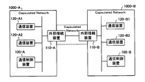
- FIG. 47 (a) and 47 (b) are schematic diagrams showing an example of connection modes of various devices in a virtual environment using DOVE.
- the network indicated as “Capsulated ⁇ ⁇ ⁇ Network” is a network in which the encapsulation communication by DOVE is performed.
- the connection management server 900 Inquires about where the communication partner exists and whether it can be connected, etc., and obtains information necessary for capsuling and then performs capsuling communication with other virtual switches and gateway devices. For example, the connection management server 900 resolves the inquiry based on a predetermined communication connection policy.
- the method in which the connection management server 900 centrally manages communication destination terminal information and communication connection policies is such that the communication path to the connection management server 900 and the connection management server 900 becomes a failure concentration point or load concentration point when the encapsulation environment increases. There was a problem of becoming a point.
- connection management server 900-1 and the connection management server 900-2 that require synchronization are connected via the gateway device 910-1, the WAN, and the gateway device 910-2. Yes. In such a case, there is a problem that there is no certainty that the communication path in the WAN is continued, and the consistency of the setting data cannot be maintained.
- Hyper-V is an example of the same type of communication method (centrally managed communication method).
- VXLAN and NvGRE define a gateway function for enabling connection to an external network.
- FIG. 48 is a schematic diagram illustrating an example of a connection mode of various devices in a virtual environment using VXLAN or NvGRE.
- the network indicated as “Capsulated Network” is a network in which VXLAN or NvGRE is used for encapsulation communication.
- a central management server is not necessarily required.
- a gateway device 910 having a network conversion function for converting an internal network protocol such as VXLAN or NvGRE and a protocol of an external network is used to connect virtual environments with different locations via the external environment network. It is also possible to substantially expand the encapsulation environment. However, in the case of VXLAN or NvGRE, the gateway device 910 serving as a communication connection point with an external network performs decapsulation / encapsulation in order to connect to the external VLAN network, or between the VLAN-ID and the internal ID. It is necessary to perform ID matching.
- VXLAN and NvGRE assume a VLAN network which is a general network as an external network, and further, all communication devices in the system regardless of inside or outside of the gateway device 910 are connected to the connection management server 900 or the like. This is because it is assumed that the central management apparatus is controlled. Note that the technology described in Patent Document 1 is also used in that gateway devices that connect between virtual environments perform decapsulation / capsulation, or perform ID matching between a VLAN-ID and an internal ID. It is the same.
- decapsulation / encapsulation or ID matching for network connection with a VLAN network or the like is also necessary in communication between virtual environments. Furthermore, since the simple one-to-one matching is not possible when the ID spaces are different, great contrivance is required for management and control of ID matching.
- connection setting and adjustment with an external environment network such as association of identifiers related to the virtual network inside and outside the virtual environment are required, and a virtual tenant or virtual network cannot be flexibly constructed.
- an object of the present invention is to provide a communication system, a communication device, a communication method, and a control program that can connect between virtual environments without conversion of identifiers related to virtual networks.
- the communication system is a communication system that connects between virtual environments that perform communication within the self-virtualized environment using packets encapsulated by the overlay method, and is provided in each of the virtualized environments.
- a communication control device that manages at least a packet transfer position in communication in a virtual environment, and a communication connection point that is provided in each of the virtual environments and that is used for communication in the own virtual environment and communication between the virtual environments
- a communication device, and the communication device sets a virtual network identifier to be used for communication in the own virtualized environment with a linked external communication device that is a communication device provided in another virtualized environment to be linked.
- the attached packet is used to query the communication terminal and transfer the packet.
- the virtual network attached to the packet is sent.
- a transfer control unit that processes the packet in accordance with a transfer rule specified by using the work identifier and the communication destination information and notified from the communication control device in the own virtualization environment, To do.
- a communication apparatus is a virtual environment that performs communication in a self-virtualized environment using a packet encapsulated by an overlay method, and at least manages a packet transfer position in the communication in the self-virtualized environment.
- a transfer control unit that performs packet transfer control within the device, and the transfer control unit is a communication device that is connected via an external environment communication interface, and is provided in another virtual environment that is to be linked.
- a packet with a virtual network identifier to be used for communication within the self-virtualized environment with a linked external communication device that is a communication device Communications specified by the virtual network identifier and communication destination information attached to the packet when the external environment communication interface receives a packet from the linked external communication device
- the packet is processed in accordance with a transfer rule notified by the communication control device.
- a communication method is a communication device provided in a virtual environment that performs communication in a self-virtualized environment using a packet encapsulated by an overlay method, and is a communication connection point on the self-virtualized environment side.
- a communication device having an internal environment communication interface and an external environment communication interface that is a communication connection point on the external environment side uses the packet with the virtual network identifier used in the self-virtualized environment to set the external environment communication interface.
- the communication device is inquired of the communication terminal from the internal environment communication interface to the cooperation external communication device which is a communication device connected via the communication device and is a communication device provided in another virtual environment to be linked. Transfer the received packet to the external environment communication interface with the virtual network identifier attached to the packet.
- the packet is processed according to a transfer rule notified from a communication control device that manages at least a transfer position of the packet in communication within the self-virtualized environment.
- a control program is a communication device provided in a virtual environment that performs communication in a self-virtualized environment using a packet encapsulated by an overlay method, and is a communication connection point on the self-virtualized environment side Using a packet with a virtual network identifier to be used in the self-virtualized environment on a computer provided in a communication device having an internal environment communication interface and an external environment communication interface that is a communication connection point on the external environment side, the external environment Processing for inquiring a communication terminal to a linked external communication device that is a communication device that is connected via a communication interface and that is provided in another virtualized environment that is targeted for cooperation, from the internal environment communication interface The received packet is attached to the external environment communication interface with the virtual network identifier attached to the packet.
- a communication transfer rule specified based on the virtual network identifier and communication destination information attached to the packet is received from a linked external communication device via the external environment communication interface.
- a communication transfer rule notified from a communication control device that manages at least a transfer position of a packet in communication within the own virtualization environment a process for transferring the packet into the own virtualization environment is executed. .
- virtual environments can be connected without conversion of identifiers related to virtual networks.
- FIG. 1 is a schematic diagram showing an example of a connection mode of various devices in a communication system according to the present invention.
- the present invention is encapsulated in the same manner as the communication (internal communication) in each virtual environment as long as the virtual environment is of the same type.
- FIG. 1 it is assumed that there are a virtual machine system A and a virtual machine system B that each realize a virtualized environment that is to be linked to each other.
- a communication device that is an external connection point that is a communication connection point with the external environment in the encapsulation communication in each virtual environment (a device corresponding to a general gateway device, and a GW A and Assume a virtual environment C in which GW B ) is a communication device of the own virtual environment.
- packet delivery within each virtual environment (virtual environment by virtual machine system A, virtual environment by virtual machine system B, and virtual environment C) is left to the delivery control of each virtual environment, and the transmission source
- the virtual network identifier used by the virtual environment is also inherited by the destination virtual environment.
- the identifier has a unique value among the virtual machines to be linked.
- the present invention includes a communication control server (Control Server in the figure) that controls communication in at least a virtual environment to be linked.
- a communication device (hereinafter referred to as an external connection device) serving as an external connection point of each virtual environment includes a virtual network identifier to which the own external connection device belongs in a packet and inquires about the external environment.
- the external environment mainly refers to another virtual environment in which the own virtual environment is linked, but may include other environments.
- the virtual environment C can include an existing network node.
- each external connection device can determine whether communication is possible based on information included in a packet received from the external environment. What is necessary is just to have the function to determine a communication aspect.
- FIG. 2 is a block diagram illustrating a configuration example of the communication system according to the first embodiment of the present invention.
- the communication system shown in FIG. 2 is a communication system for connecting two virtual environments (for example, the virtual environment 1000-A and the virtual environment 1000-B).
- each of the virtual environments to be connected is a communication control device 100 that controls capsulation communication in the self-virtualized environment and a communication device that is an external connection point of the self-virtualized environment. And an external connection device 110.
- each virtual environment further includes a communication device 120 that performs capsule communication.
- virtualized environment has XX
- the computer system that implements the virtualized environment has XX
- providing two or more virtualization environments means that two or more physically different computer systems each realizing a virtualization environment are provided.
- the virtualization environment 1000-A includes a communication control device 100-A, an external connection device 110-A, a communication device 120-A1, and a communication device 120-A2.
- the virtual environment 1000-B includes a communication control device 100-B, an external connection device 110-B, a communication device 120-B1, and a communication device 120-B2.
- a communication terminal such as a VM may be connected under the communication device 120.
- the communication device 120 and the communication terminal may be constructed on the same physical server.
- the communication device 120 is, for example, a device that performs encapsulation communication using a predetermined virtual network identifier assigned to an interface of the own device in the own virtualization environment. More specifically, the communication device 120 is a virtual switch that, when receiving a packet from a subordinate VM or the like, performs encapsulation using the L2 over L3 encapsulation technology and outputs it to a virtual network in the own virtualization environment. Also good.
- the communication control device 100 may be a network control controller generally called a connection server.
- the communication control apparatus 100 holds terminal information that is information on a communication terminal to be managed as internal information.
- the terminal information is, for example, information indicating where a communication IF of which communication terminal (VM) exists in a switch or gateway (external connection device) included in a virtual environment managed by the terminal information.
- the communication control apparatus 100 holds information that the MAC address MAC1 of the IP address IP1, which is one of the interfaces of the VM1, is on the VS1, as terminal information.
- the communication control device 100 determines from the internal information a communication device (more specifically, a communication destination terminal exists). The interface) as a transfer position, and a function for determining whether communication is possible. Further, when the terminal information of the communication destination terminal exists in the internal information and the transfer position can be specified, the communication control apparatus 100 sets a transfer rule relating to communication with the communication destination terminal to be inquired to the inquiry source communication apparatus. Notice. When the notification is made with respect to a communication destination inquiry, it may be called a communication destination inquiry response.
- the communication control apparatus 100 requests the communication apparatus in the own virtualization environment to search for the communication destination.
- the communication control device 100 When the communication control device 100 is notified of the update (registration, change or deletion) of the terminal information from the communication device in the self-virtualized environment, the communication control device 100 rewrites the internal information and updates the transfer rule to the related communication device. I do.
- the communication control device 100 when registering, changing, or deleting terminal information managed by itself due to the disappearance, transfer, or change of communication availability of virtual machines or communication devices, transfers them to related communication devices. Notify rule updates.
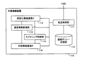
- FIG. 3 is a block diagram illustrating a configuration example of the external connection device 110.
- the external connection device 110 illustrated in FIG. 3 includes a transfer control unit 111, a communication policy storage unit 112, a communication information conversion unit 113, a capsulation control unit 114, a virtual environment communication IF 115, and an external environment communication IF 116. .
- the transfer control unit 111 controls communication within the own device. More specifically, the transfer control unit 111 refers to the communication policy storage unit 112 when the virtual environment communication IF 115 receives a packet, that is, when a packet is received from a communication device in the own virtual environment, Check if the transfer rules that match the packet are maintained. For example, the transfer control unit 111 determines whether or not the transfer rule matches the received packet, the communication information of the packet before encapsulation, that is, the communication information of the internal message, the virtual network identifier attached by the encapsulation, Determine using.
- the communication information is predetermined control information required to deliver the packet to a designated terminal, such as information indicating the destination of the packet and information indicating the transmission source of the packet.
- communication is identified using not only the communication information of the internal message but also the virtual network identifier.
- communication information information used for transfer control in the communication network in the virtual environment
- the information attached to the header portion of the packet after encapsulation is applicable.
- the information on the terminal (communication destination terminal) that actually becomes the final destination of the packet and the information on the terminal (communication source terminal) of the packet are called “communication destination information” and “communication source information”.
- information indicating the destination and the information indicating the transmission source attached to the header portion of the internal message are applicable.
- the communication destination information and the communication source information may be collectively referred to as “communication terminal information”.
- the former may be referred to as destination information and source information in order to distinguish between information indicating the destination and information indicating the source included in the “communication information” and communication destination information and source information.
- a device indicated by transmission destination information may be referred to as a transmission destination device
- a device indicated by transmission source information may be referred to as a transmission source device.
- the transfer control unit 111 performs transfer control to the external environment when a matching transfer rule exists as a result of the search for the transfer rule and the output to the external environment communication IF 116 is indicated by the transfer rule. .
- the transfer control unit 111 causes the communication information conversion unit 113 to rewrite the transmission source information of the received packet with information indicating the own device, and the transmission destination information is information indicating another external connection device.
- the rewritten packet is transferred to the external environment communication IF 116 and requested to be sent to the external environment.
- the transfer control unit 111 determines that the communication destination information of the packet and the virtual network if the inquiry about the communication destination for the received packet is within the specified number of times. Using the identifier, the communication control apparatus 100 in the self-virtualized environment is inquired about the communication destination. Note that the transfer control unit 111 may also use communication source information.
- the designated number of inquiries may be a value determined by the user or system designer, for example, and may include zero. Further, the designated number of times of inquiry may be a value that varies based on a tendency by measuring statistics of the actual number of times of inquiry.
- the transfer control unit 111 discards the received packet.
- the transfer control unit 111 When the external environment communication IF 116 receives a packet, that is, when a packet is received from the external environment side, the transfer control unit 111 refers to the communication policy storage unit 112 and holds a transfer rule that matches the received packet. Check if it is. The transfer control unit 111 also uses a communication destination information and a virtual network identifier attached to the packet to determine whether or not the transfer rule matches the received packet even for the packet received from the external environment. What is necessary is just to judge.
- the transfer control unit 111 if the transfer rule that matches and the output to the virtual environment communication IF 115 is indicated by the transfer rule, Perform transfer control.
- the transfer control unit 111 first specifies the transfer position of the received packet based on the found transfer rule as transfer control into the self-virtualized environment. Then, the transfer control unit 111 causes the communication information conversion unit 113 to rewrite the transmission source information of the received packet with information indicating its own device, and also rewrites the transmission destination information with information indicating the specified transfer position. Then, the rewritten packet is transferred to the virtual environment communication IF 115 and requested to be sent to the own virtual environment.
- the transfer control unit 111 determines whether the internal message of the received packet is a terminal information update message.
- the transfer control unit 111 notifies the communication control apparatus 100 in the own virtualization environment of the terminal information update (addition). For example, as the terminal information, the transfer control unit 111 notifies that the terminal indicated by the terminal information update message is under the external connection device 110 (more specifically, that the terminal is under the external environment communication IF 116). May be. As a result, the internal information of the communication control apparatus 100 in the self-virtualized environment is updated.
- the transfer control unit 111 finds that there is no matching transfer rule as a result of the search for the transfer rule, and the inquiry of the communication destination for the received packet is within the specified number of times, or the terminal information to the communication control device 100 If the update notification is received, an inquiry about the communication destination of the received packet is made to the communication control apparatus 100 in the own virtualization environment.
- the transfer control unit 111 discards the received packet.
- the transfer control unit 111 when requested to search for a communication destination from the communication control device 100 in the self-virtualized environment, creates a search message for the other external connection device 110 in the external environment. Further, the transfer control unit 111 acquires a virtual network identifier to be searched, passes it to the capsuling control unit 114 together with the created search message, and requests capsuling and transfer to the external environment communication IF 116.
- a method for acquiring the search target virtual network identifier for example, there is a method of acquiring from a search request.
- a method of acquiring from a search request referring to virtual network information included in domain information obtained when self-virtualized environment information is obtained when a search request is received, a virtual network identifier with which the self-device can communicate is obtained. A method is mentioned.
- the communication control apparatus 100 uses a domain information for an arbitrary group of virtual machines and communication apparatuses in its own virtualized environment to communicate between virtual machines, between communication apparatuses, and between virtual machines and communication apparatuses. May be managed.
- the domain information may be, for example, information indicating which range of virtual machines and virtual network environments can be handled, or information indicating a unit of a node associated with a setting to be connectable.
- the communication control apparatus 100 for each domain (more specifically, a computer group that configures an arbitrary virtual network) created in the virtual environment, a domain ID, a virtual network identifier as virtual network information, and Self-virtualized environment information including domain information including information associated with port information and communication permitted by the domain (communication between different domains, which domain is permitted, etc.) You may hold as one of these.
- the communication control apparatus 100 may hold a connection rule, virtual network information to which the connection rule is applied, and information indicating a node unit in association with each other without using a domain ID or the like.
- the search message includes information on the communication terminal to be searched.
- An example of the search message may use a message format for requesting a search for a communication destination from the communication control apparatus 100.
- a node search packet format of an existing terminal discovery protocol such as ARP (Address Resolution Protocol) or ICMP (Internet Control Message Protocol) may be used.
- the transfer control unit 111 When the transfer control unit 111 is notified of the update of the transfer rule from the communication control device 100 in the self-virtualized environment, the transfer control unit 111 registers, deletes or deletes the corresponding transfer rule from the communication policy storage unit 112 according to the instruction content. Make a change. In addition, when the notified content relates to registration, deletion, or change of terminal information, the transfer control unit 111 creates a terminal information update message for the other external connection device 110 in the external environment. In addition, the transfer control unit 111 acquires the virtual network identifier of the virtual network to which the own device belongs, passes it to the encapsulation control unit 114 together with the created terminal information update message, and requests the encapsulation and transfer to the external environment communication IF 116. .
- a method for acquiring the virtual network identifier of the virtual network to which the own device belongs there is a method of acquiring from the domain information or virtual network information obtained when acquiring the own virtualization environment information at the time of update notification or the like.
- the terminal information update message includes terminal information related to the communication terminal to be changed. Further, the terminal information update message may further include information indicating an operation instruction for the terminal information (for example, registration, change or deletion of a transfer rule related to the terminal indicated by the terminal information).
- An example of the terminal information update message may use a transfer rule update notification format from the communication control device 100.
- a node response packet format of an existing terminal discovery protocol such as ARP or ICMP may be used.
- the communication policy storage unit 112 stores the transfer rule notified from the communication control device 100 in accordance with the control from the transfer control unit 111.
- the transfer rule stored in the communication policy storage unit 112 may be, for example, information in which information indicating application conditions is associated with information indicating an execution method such as how to process and output.
- the transfer rule includes terminal information including information for identifying a communication terminal and a transfer position (location of the terminal) of a packet addressed to the terminal, and a method for rewriting information on a received packet when transferring to the transfer position. And information including information such as a capsule method.
- the information indicating the application condition and the information specifying the communication terminal include not only the packet communication destination information and the communication source information but also the virtual network identifier.
- Examples of information indicating application conditions include whether or not the capsule is encapsulated, a pair of virtual network identifier and communication destination information when encapsulated, communication source information, communication information, and a combination thereof. Can be mentioned.
- Examples of information indicating the execution method include an encapsulation command or a decapsulation command, a virtual network identifier acquisition method at the time of encapsulation, information indicating a communication information rewriting method, information to the communication control device 100 The presence / absence of notification and a combination thereof may be mentioned.
- the communication information conversion unit 113 converts the communication information of the designated packet in response to a request from the transfer control unit 111.
- the encapsulation control unit 114 performs encapsulation and decoupling of the designated packet in response to a request from the transfer control unit 111. For example, in response to a request from the transfer control unit 111, the encapsulation control unit 114 performs encapsulation on a control message such as a search message or a terminal information update message, or encapsulates the control packet received from the external environment. For example, decapsulation is performed. In addition, for example, the encapsulation control unit 114 can perform encapsulation or decapsulation for realizing communication with a subordinate terminal for a designated packet in response to a request from the transfer control unit 111. .
- the virtual environment communication IF 115 is an interface serving as a communication connection point on the own virtual environment side.
- the virtual environment communication IF 115 is connected to a communication network in the own virtual environment, and receives (receives), for example, a packet transmitted from the communication device 120 in the own virtual environment from the communication network. Also, the virtual environment communication IF 115 outputs (transmits), for example, a packet addressed to the communication device 120 in the own virtual environment on the communication network.
- the virtualization environment communication IF 115 notifies the transfer control unit 111 of the fact.
- the external environment communication IF 116 is an interface serving as a communication connection point on the external environment side.
- the external environment communication IF 116 is connected to a communication network in the external environment.
- the external environment communication IF 116 receives (receives) a packet transmitted from another external connection device 110 in the external environment from the communication network.
- the external environment communication IF 116 outputs (transmits), for example, a packet addressed to another external connection device 110 in the external environment to the communication network.
- the external environment communication IF 116 notifies the transfer control unit 111 to that effect.
- the transfer control unit 111, the communication information conversion unit 113, and the encapsulation control unit 114 are realized by an information processing apparatus such as a CPU that operates according to a program stored in a storage unit, for example.
- the communication policy storage unit 112 is realized by a storage device, for example.
- the virtual environment communication IF 115 and the external environment communication IF 116 are realized by a data input / output device that inputs and outputs data via a network such as a network card, for example.
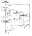
- FIG. 4 to 7 are flowcharts showing an example of the operation of the external connection device of the present embodiment.
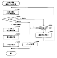
- FIG. 4 is a flowchart showing an example of the operation at the time of packet reception from the self-virtualization environment side.
- FIG. 5 is a flowchart illustrating an example of an operation at the time of packet reception from the external environment (cooperative virtualization environment) side.
- FIG. 6 is a flowchart illustrating an example of an operation when a communication destination search request is received from the communication control apparatus 100 in the self-virtualized environment.
- FIG. 7 is a flowchart illustrating an example of an operation when receiving a transfer rule update notification from the communication control apparatus 100 in the self-virtualized environment.
- the flowchart shown in FIG. 4 starts when the virtual environment communication IF 115 receives the packet. At this time, the virtualization environment communication IF 115 notifies the transfer control unit 111 of reception of the packet.
- the transfer control unit 111 refers to the communication policy storage unit 112 and searches for a transfer rule that matches the received packet (step S101).
- the transfer control unit 111 determines whether the output destination is the external environment communication IF 116 (step S102).
- the transfer control unit 111 controls transfer of the received packet to the external environment. Specifically, the transfer control unit 111 requests the communication information conversion unit 113 to convert the communication information of the received packet. At this time, the transfer control unit 111 rewrites the transmission source information with information indicating its own device (more specifically, its external environment communication IF 116), and the transmission destination information as another external connection device 110 in the external environment. The communication information conversion unit 113 is requested to rewrite the information indicating (more specifically, the external environment communication IF 116).
- the transfer control unit 111 may store, for example, information on the other external connection device 110 in advance, or may acquire the information by making an inquiry to a dedicated configuration tool.
- the communication information conversion unit 113 converts the communication information of the received packet based on the request from the transfer control unit 111 (step S103). In addition, the communication information conversion unit 113 transfers the packet for which the conversion process has been completed to the external environment communication IF 116. The external environment communication IF 116 outputs the packet to the external environment communication network (step S104).
- step S105 determines whether or not the communication destination inquiry for the received packet is within the specified number of times. If it is within the specified number of times (Yes in step S105), the transfer control unit 111 inquires the communication control apparatus 100 about the communication destination of the received packet (step S106).
- step S106 After the inquiry about the communication destination in step S106, when a transfer rule suitable for the received packet is notified as an inquiry response or when the inquiry is terminated due to a timeout or the like, the transfer control unit 111 returns to step S101, Redo transfer control. If there is an inquiry response from the communication control apparatus 100, the transfer control unit 111 may omit step S101 and proceed to the process of step S102 based on the notified transfer rule.
- step S101 when the transfer rule found in step S101 has a pattern other than the above, such as an output destination other than the external environment communication IF 116 (step S102c), a communication destination inquiry for the received packet is designated.
- the transfer control unit 111 discards the received packet (step S107). For example, the transfer control unit 111 may request the virtual environment communication IF 115 to discard the received packet and discard the received packet.
- the external connection device 110 performs the process of the own virtual environment on the packet received by the virtual environment communication IF 115 by being transferred from the communication device in the virtual environment to which the own device belongs. If transfer to the external environment is possible according to the transfer rule notified from the communication control device 100, the transfer can be made toward the external connection device 110 in another virtual environment without decapsulation.
- a virtual network identifier used in each virtualization environment is treated as a unique identifier in the communication system. That is, in the encapsulation communication between virtual environments, the identifier of the virtual network to which the communication destination terminal or the communication source terminal belongs is used as it is. Therefore, the external connection device 110 in the other virtual environment receiving the packet designates it as a communication destination according to the transfer rule in the own virtual environment based on the communication terminal information and the virtual network identifier included in the received packet.
- the packet may be delivered to the received terminal or a device that can be transferred to the terminal.
- the flowchart shown in FIG. 5 starts when the external environment communication IF 116 receives a packet. At this time, the external environment communication IF 116 notifies the transfer control unit 111 of packet reception.
- the transfer control unit 111 When notified of the reception of the packet from the external environment communication IF 116, the transfer control unit 111 refers to the communication policy storage unit 112 and searches for a transfer rule that matches the received packet (step S111).
- the transfer control unit 111 determines whether the output destination is the virtual environment communication IF 115 (step S112).
- the transfer control unit 111 When the output destination is the virtual environment communication IF 115 (a in step S112), the transfer control unit 111 performs transfer control on the received packet into the own virtual environment. Specifically, the transfer control unit 111 requests the communication information conversion unit 113 to convert the communication information of the received packet. At this time, the transfer control unit 111 rewrites the transmission source information of the packet to information indicating its own device (more specifically, its virtual environment communication IF 115), and converts the transmission destination information to the transfer position included in the transfer rule. The communication information conversion unit 113 is requested to rewrite the information to indicate information.
- the communication information conversion unit 113 converts the communication information of the received packet based on the request from the transfer control unit 111 (step S113). Further, the communication information conversion unit 113 transfers the packet for which the conversion process has been completed to the virtual environment communication IF 115.
- the virtual environment communication IF 115 outputs the packet to the communication network of the own virtual environment (step S114).
- step S111 determines whether the received packet is a terminal information update message. It is determined whether or not (step S115).
- step S115 If the received packet is a terminal information update message (Yes in step S115), the transfer control unit 111 updates the terminal information update (registration, registration) to the communication control device 100 in the own virtualization environment based on the terminal information update message. Change or deletion) is notified (step S116). Note that after the terminal information update notification, the process proceeds to step S118.
- step S115 determines whether or not the inquiry about the communication destination for the received packet is within the specified number of times.
- step S117 determines whether or not the inquiry about the communication destination for the received packet is within the specified number of times.
- step S118 the transfer control unit 111 inquires the communication control device 100 of the self-virtualized environment about the communication destination of the received packet. If the transfer rule regarding the packet is notified as an inquiry response after the inquiry about the communication destination, the process proceeds to step S112 based on the notified transfer rule. On the other hand, if the inquiry about the communication destination is terminated due to timeout or the like, the process proceeds to step S119.
- step S119 the transfer control unit 111 determines whether the received packet is a control message. If the received packet is a control message (Yes in step S119), the process proceeds to step S120. On the other hand, if the received message is not a control message (No in step S119), the search is repeated from the search for the transfer rule (return to step S111).
- step S111 if the transfer rule found in step S111 has a pattern other than the above, such as an output destination other than the virtual environment communication IF 115 (step S112c), the process proceeds to step S120.
- step S120 the transfer control unit 111 discards the received packet.
- the transfer control unit 111 determines that the output destination is other than the virtual environment communication IF 115 (step S112c), or the communication destination inquiry for the received packet exceeds the specified number of times. (No in step S117) or, after the received packet is a control message, the communication packet is inquired once (Yes in step S119), and the received packet is discarded.
- the transfer control unit 111 may request the external environment communication IF 116 to discard the received packet and discard the received packet.
- the external connection device 110 automatically responds to a packet received by the external environment communication IF 116 by being transferred from another external connection device 110 outside the virtual environment to which the self device belongs.
- the transfer rule notified from the communication control apparatus 100 in the virtual environment when transfer is possible in the virtual environment, the transfer can be performed toward the transfer position indicated in the transfer rule without decapsulation.
- the flowchart shown in FIG. 6 starts when the external connection apparatus 110 receives a communication destination search request from the communication control apparatus 100 in the self-virtualized environment.
- the transfer control unit 111 When receiving the communication destination search request from the communication control apparatus 100, the transfer control unit 111 creates a search message (step S131). Then, the transfer control unit 111 acquires a virtual network identifier to be searched, passes it to the capsuling control unit 114 together with the created search message, and requests capsuling. For example, the transfer control unit 111 includes the virtual network identifier in a capsuling header part that is a header part newly added by capsuling, sets the transmission source apparatus as its own apparatus, and sets the transmission destination apparatus as an external environment. Requests that another external connection device 110 that is linked to the device creates a encapsulation packet.
- the encapsulation control unit 114 performs the encapsulation of the search message in response to a request from the transfer control unit 111 (step S132). Then, the encapsulation control unit 114 transfers the generated encapsulation packet to the external environment communication IF 116.
- the external environment communication IF 116 outputs the packet to the external environment communication network (step S133).
- a search message for searching for a communication destination terminal outside the virtual environment can be transmitted to another external connection device 110 in the external environment together with the virtual network identifier. Accordingly, in response to a search request from the communication control apparatus 100 in its own virtual environment, the external connection apparatus 110 that is the cooperation destination can make an inquiry about the communication destination to the communication control apparatus 100 in the own virtual environment. it can.
- the flowchart shown in FIG. 7 starts when the external connection apparatus 110 receives a transfer rule update notification from the communication control apparatus 100 in the own virtualization environment.
- the transfer control unit 111 When receiving the transfer rule update notification from the communication control apparatus 100, the transfer control unit 111 registers, changes, or deletes the transfer rule in the communication policy storage unit 112 according to the update content (step S141). Note that the transfer control unit 111 may return an update response to the communication control device 100 if necessary.
- the transfer control unit 111 determines whether or not the update content of the transfer rule is accompanied by the update of terminal information (step S142). For example, the transfer control unit 111 determines that the update of the terminal information is accompanied when the update adds or deletes the transfer rule or changes the information identifying the communication included in the existing transfer rule. May be. In addition, for example, if the update content is a change in transfer position or a change in the encapsulation method, the transfer control unit 111 may determine that the terminal information is not updated.
- the transfer control unit 111 creates a terminal information update message (step S143) when the update content of the transfer rule is accompanied by the update of the terminal information (Yes in step S142). Then, the transfer control unit 111 acquires the virtual network identifier of the virtual network to which the own device belongs, and transfers the virtual network identifier together with the created terminal information update message to the capsuling control unit 114 to request capsuling. For example, the transfer control unit 111 includes the virtual network identifier in a capsuling header portion, and sets the transmission source device as its own device, the transmission destination device as an external environment, and other external connection devices 110 that are linked to the own device. Request that the encapsulation packet be created.
- the encapsulation control unit 114 performs the encapsulation of the terminal information update message in response to a request from the transfer control unit 111 (step S144). Then, the encapsulation control unit 114 transfers the generated encapsulation packet to the external environment communication IF 116.
- the external environment communication IF 116 outputs the encapsulation packet (step S145).
- the transfer control unit 111 may end the process for the notification as it is.
- the terminal information update message of the terminal related to the update content is sent to the other external connection device 110 in the external environment triggered by the transfer rule update notification from the communication control device 100 in the self-virtualized environment. Can be transmitted along with the virtual network identifier.
- the addition or deletion to the communication control device 100 of its own virtual environment is added to the external connection device 110 of the cooperation destination. It can be notified as an update of a subordinate terminal.
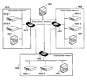
- the computer environment shown in FIG. 8 is an example in which a virtual environment 1010 and a virtual environment 1020 are linked.
- the virtual environment 1010 includes a communication control server 1011 (CS1) equipped with a communication control device 100 that controls capsuling communication in the virtual environment 1010, and an external connection device that serves as a communication connection point between the virtual environment and the outside. 110, a gateway device 1012 (GW1) on which 110 is mounted, and a plurality of VM servers (VM server 1013-1 and VM server 1013-2) that execute VMs.
- CS1 communication control server 1011
- GW1 gateway device 1012
- VM server 1013-1 and VM server 1013-2 a plurality of VM servers
- the virtual environment 1020 includes a communication control server 1021 (CS2) equipped with the communication control apparatus 100 that controls capsuling communication in the virtual environment 1020, and an external communication connection point between the own virtual environment and the outside.
- a gateway apparatus 1022 (GW2) on which the connection apparatus 110 is mounted and a plurality of VM servers (VM server 1023-1 and VM server 1023-2) for executing the VM are provided.
- the virtualization environment 1010 and the virtualization environment 1020 are connected via the GW1 and the GW2.
- VM1 which is one of the communication terminals included in the virtual environment 1010 and VS1 which is one of the virtual switches are both executed on the VM server 1013-1.
- VM2 which is one of the communication terminals included in the virtual environment 1020 and VS2 which is one of the virtual switches are both executed on the VM server 1023-2.
- each of CS1 and CS2 acquires the position of the VM in the self-virtualized environment as terminal information from a setting value or the like or by learning.
- IP address is held as one piece of information for identifying a terminal included in the terminal information.
- multilayer protocol information for example, MAC address information etc.
- address information is an L3 protocol having an L2 frame having an ID space expanded by overlay technology, such as VXLAN and NvGRE, in the encapsulation communication within each virtualization environment and the encapsulation communication between the virtualization environments.
- L3 protocol using an IP address is used, but the protocol used in the encapsulation communication is not limited to the above.
- the protocol of the capsuling communication in each virtual environment and the capsuling communication between the virtual environments may be different.
- FIG. 9 is a sequence diagram showing an example of the communication terminal discovery operation of the present embodiment.
- FIG. 10 is a sequence diagram illustrating an example of a communication transmission operation in the present embodiment.
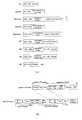
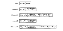
- FIG. 11A is an explanatory diagram schematically illustrating an example of a packet used in the examples illustrated in FIGS. 9 and 10.
- VM1 generates a packet addressed to VM2 and transmits it to VS1 (M1 in the figure).
- vIP 2 represents the IP address of the VM2.
- VS1 Since VS1 does not hold a transfer rule that matches the received packet, it queries CS1 for the communication destination (request1 in the figure).
- CS1 receives the inquiry of the communication destination, but cannot resolve the address of VM2 that is the destination terminal, and therefore requests GW1 to search for the communication destination (query1 in the figure).
- GW1 Upon receiving a communication destination search request from CS1, GW1 creates a search message, further performs encapsulation, and transmits it to the other linked GW2 (GWquery1 in the figure).
- the search message includes at least the VIP 2 that is the IP address of the VM 2 as information on the terminal to be searched.
- the GW 1 acquires the virtual network identifier to be searched and includes it in the capsuling header part, and uses the pIP g1 that is the IP address of the GW 1 that is the own device as the source information, and is linked as destination information.
- the search message is encapsulated using pIP g2 , which is the IP address of GW2.
- GW2 has not learned anything about VM2 at this time.
- CS2 has already acquired terminal information related to VM2, for example, from a setting value at the time of startup.
- the GW 2 When the GW 2 receives the search message encapsulation packet from the cooperation destination GW 1, there is no transfer rule that matches the received packet, the received packet is not a terminal information update message, and a communication destination inquiry about the received packet is received. Since it is within the specified number of times (in this example, once), the communication destination of the received packet (here, the communication destination to be searched) is inquired of CS2 (request2 in the figure).
- CS2 Since CS2 knows the location of VM2, as a response to the inquiry, CS2 sends a transfer rule update notification indicating VS2 IP address VIP s2 as a transfer location to GW2 for the packet addressed to VM2 ( Answer1 in the figure).
- the GW 2 When the GW 2 receives the transfer rule update notification from the CS 2, the GW 2 updates the transfer rule in the communication policy storage unit 112 based on the notified update content. Further, since the update is an update accompanied by the addition of terminal information related to VM2, the GW2 creates a terminal information update message, performs encapsulation, and transmits the message to the GW1 (GW answer 1 in the figure). For example, the GW 2 may create a terminal information update message including terminal information indicating that the VIP 2 is under the control of the GW 2 that is the own device as the terminal information regarding the VM 2 .
- GW2 acquires the virtual network identifier of the virtual network to which the own device belongs, includes the acquired virtual network identifier in the encapsulation header portion, and is the IP address of GW2 that is the own device as transmission source information.
- the terminal information update message is encapsulated using pIP g1 , which is the IP address of the other GW 1 linked as transmission destination information.
- the encapsulation packet of the terminal information update message is transmitted to the other GW1.
- the GW1 When the GW1 receives the encapsulation packet of the terminal information update message from the cooperation destination GW2, there is no transfer rule that matches the received packet, and the received packet is a terminal information update message. Based on this, CS1 is notified of the update of terminal information related to VM2 (answer2 in the figure). For example, the GW 1 sends a terminal information update (registration) notification to the CS 1 indicating that the terminal specified by the terminal information included in the received terminal information update message is a terminal under the GW 1 as its own device. Also good. At this time, the GW 1 notifies the virtual network identifier notified from the GW 2 as it is as the virtual network identifier to which the VM 2 belongs.
- CS1 updates internal information according to the notified update content.
- CS1 receives the update notification of the terminal information and transmits a response (transfer rule update notification) to the communication destination inquiry from VS1 that has been held, or is applied to the packet addressed to VM2 to GW1.
- a transfer rule update notification may be transmitted.
- the CS1 of the virtual environment 1010 can discover the VM2 existing in the other virtual environment 1020 by the cooperation of the GW1 and the GW2. Therefore, it can be seen that CS1 only has to transfer a packet addressed to VM2 to GW1.
- a central management server or the like is not required. Even if there are a plurality of other external connection devices 110 that are linked, once the transfer destination is learned, communication between the virtual environments is not distributed processing by multicast or multiple unicasts, Since it can be realized by unicast communication with a specific GW, communication is optimized.
- the GW 1 inquires the CS 1 about the communication destination of the received packet that is the encapsulation packet of the terminal information update message from the GW 2.
- CS 1 receives the inquiry about the communication destination, but since the packet is a terminal information update message and corresponds to a message addressed to the communication control apparatus 100, CS 1 replies that the transfer rule is not set. Then, the GW 1 that has received the notification that the communication rule is not set from the CS 1 discards the packet because the packet is a control message.
- the VS1 and the GW1 may update their own transfer rules according to the update contents.
- VM1 generates a packet addressed to VM2 and transmits it to VS1 (M1 in the figure). Since VS1 does not hold a transfer rule that matches the received packet, CS1 makes an inquiry about the communication destination (request1 in the figure).
- CS1 Since CS1 has learned GW1 as the transfer position of the packet addressed to VM2, it returns a transfer rule update notification indicating GW1 as the transfer position of the received packet (answer3 in the figure).
- VS1 receives the transfer rule update notification from CS1 and updates the transfer rule held by itself. Then, VS1 performs encapsulation of the received packet according to the updated transfer rule, and transfers it to GW1 (M2 in the figure). At this time, the VS1 registers the virtual network identifier set in the IF with the VM1 in the encapsulation header part.
- the GW1 When the GW1 receives the encapsulation packet from the VS1 via the virtual environment communication IF 115, the GW1 refers to the communication policy storage unit 112 and extracts a transfer rule that matches the received packet. In this example, a transfer rule whose output destination is the external environment communication IF 116 is extracted. In accordance with the extracted transfer rule, GW1 rewrites the source information of the received packet to pIP g1 that is the IP address of GW1 that is the own device, and pIP that is the IP address of the other GW2 that cooperates with the destination information Rewrite to g2 . Then, the GW 1 outputs the rewritten packet to the external environment communication network from the external environment communication IF 116 (M3 in the figure).
- the packet is transferred from GW1 to GW2 according to the communication information of the packet.
- the external environment communication IF 116 receives the packet.
- the GW 2 refers to the communication policy storage unit 112 and extracts a transfer rule that matches the received packet.
- a transfer rule whose output destination is the virtualization environment communication IF 115 and whose transfer position is vIP s2 is extracted.
- GW2 according extracted forwarding rules, rewrites the source information of the received packet to pIP g2 is the IP address of the GW2 is its own device, and rewrites the vIP s2 is a transfer position indicating the destination information forwarding rules .
- the GW 2 outputs the rewritten packet to the communication network of the virtual environment 1020 from the virtual environment communication IF 115 (M4 in the figure).
- the packet is transferred from the GW 2 to the VS 2 according to the communication information of the packet.
- VS2 When VS2 receives the packet, it performs decapsulation (decapsulation) according to the transfer rule held by itself, and transfers it to VM2 (M5 in the figure).
- packets from VM1 to VM2 are handled as belonging to one large virtual network and can be communicated using the encapsulation communication of each virtual environment.
- FIG. 11B is an explanatory diagram showing an example of a packet format of the capsule communication in this example.
- the example shown in FIG. 11B is an example of a packet format when the encapsulation communication protocol is the VXLAN protocol.
- “original L3 frame” is an example of a packet format applied to M1 and M5 in the above example
- “new L3 frame” is applied to M2 to M4 in the above example. It is an example of a packet format.
- the VM 1 may send a message addressed to the VM 2 to the VS 1 using “original L3 Frame”.
- the IP address and MAC address of VM1 are registered in “IP DA” and “MAC DA” of “original L3 frame”.
- the IP address and the MAC address of the VM 2 are registered in “IP SA” and “MAC SA” of “original L3 Frame”.
- the VS 1 when receiving such a packet from the VM 1, the VS 1 indicates a virtual network identifier (VNI) set in an interface with the VM 1, its own IP address and MAC address, and a transfer position.
- the packet may be converted (encapsulated) into “new L3 Frame” based on the IP address and the MAC address.
- IP DA” and “MAC DA” of “original L3 Frame” are registered in “IP DA 1 ” and “MAC DA 1 ” of “new L3 Frame”.
- IP SA” and “MAC SA” of “original L3 Frame” are registered in “IP SA 1 ” and “MAC SA 1 ” of “new L3 Frame”.
- the VNI set in the interface with the own (VS1) VM1 is registered.
- the IP address and MAC address of itself (VS1) are registered in “IP DA 2 ” and “MAC DA 2 ” of “new L3 Frame”.
- IP SA 2 ” and “MAC SA 2 ” of “new L3 Frame” the IP address and MAC address of the interface that is the transfer position are registered.
- part of the communication terminal information (“IP DA” and “IP SA” of “original L3 Frame”) is included in the capsuling header part. The information may be handled as communication terminal information.
- IP DA and “IP SA” of “original L3 Frame”
- the information may be handled as communication terminal information.
- the above is an example in which VM1 and VM2 belong to the same VNI virtual network.
- the packet format is not limited to this.
- FIG. 8 shows an example in which the virtual environment is connected on a one-to-one basis
- the connection form of the virtual environment is not limited to one-to-one.
- communication information destination information and transmission source information
- a mode in which virtual environments are connected to each other is also possible.
- each virtual environment is an external connection device serving as an external connection point between the communication control server in which the communication control device 100 that controls communication in the own virtual environment is mounted and another virtual environment.
- a gateway device on which 110 is mounted includes a communication control server 1101 (CS10), a gateway device 1102-1 (GW 101) serving as an external connection point between the virtualization environment 1110, and a gateway serving as an external connection point between the virtualization environment 1120. It includes at least a device 1102-2 (GW102) and a gateway device 1102-9 (GW109) serving as an external connection point with the virtual environment 1190.
- the virtual environment 1110 has at least a communication control server 1111 (CS11) and a gateway device 1112 (GW11) serving as an external connection point with the virtual environment 1100.
- the virtual environment 1120 includes at least a communication control server 1121 (CS12) and a gateway device 1122 (GW 12) serving as an external connection point with the virtual environment 1100.
- the virtual environment 1190 includes at least a communication control server 1191 (CS 19) and a gateway device 1192 (GW 19) serving as an external connection point with the virtual environment 1100.
- GW 101 and GW 11 are connected via an external environment communication network
- GW 102 and GW 12 are connected via an external environment communication network
- GW 109 and GW 19 are connected via an external environment communication network.
- the CS 10 is another virtualization environment (a virtualization environment 1110, a virtualization environment 1120,..., A virtualization environment 1190) to be linked.
- a search request can be made to GW101, GW102,.
- the search message encapsulating packet may be transmitted to GW12 for GW102, GW19 for GW109, and the like. At this time, the address information of the gateway device as the transmission destination may be set in advance.
- communication between virtualization environments is performed using the conversion processing of transmission destination information and transmission source information via an external connection device that is an external connection point of each virtualization environment. Since packets are transferred, one huge virtual network connecting independent virtual environments can be constructed. Thereby, the user can easily construct a huge pseudo-virtualized environment formed by connecting virtualized environments at different bases. Further, in this pseudo-virtualized environment, since the virtual network identifier used by each virtualized environment is shared, control such as ID conversion inside and outside the virtualized environment and two types of ID management for the ID conversion is required. And not.
- the communication control device 100 is arranged in each virtual environment.
- the search phase is the same as in the normal network search. For discovery and communication. Therefore, it is not necessary to provide a plurality of central management servers for load distribution, and synchronization processing and consistency processing between the central management servers are not necessary, so that network restrictions for building a virtual environment can be relaxed.
- the management server (communication control device 100) that manages the connection.
- control of the central management server is important. That is, when trying to create a huge virtual environment, centralized processing of the central management server becomes a problem. For this reason, load balancing and redundancy techniques are usually used for the central management server.
- each central management server needs to have high functionality such as data synchronization, consistency maintenance, and management area control.
- in order to realize a huge virtual network by connecting the virtualization environments by the encapsulation communication by each external connection device while maintaining independent control in the virtualization environment with the external connection device as a boundary. It is possible to prevent the management server from becoming highly functional.
- the virtual networks in each virtual environment can operate, and thus communication between VMs in the virtual environment can be maintained.
- each virtual environment has its own management server, so that communication unrelated to other virtual environments can be closed and controlled in its own environment.
- This characteristic is particularly effective in the case of a network in which the virtual environments are unstable or weak in quality, for example, in the case of inter-organization cooperation or inter-base cooperation.
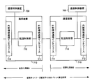
- FIG. 13 is a block diagram illustrating a configuration example of the external connection device according to the first modification of the present embodiment.
- the external connection device 210 shown in FIG. 13 is greatly different from the external connection device 110 shown in FIG. 3 in that an external connection setting storage unit 217 is further provided.
- the external connection setting storage unit 217 stores packet transfer restrictions, which are restrictions related to packet transfer between the own virtualization environment and another virtualization environment.
- the external connection setting storage unit 217 is realized by a storage device, for example.
- Other means transfer control unit 211, communication policy storage unit 212, communication information conversion unit 213, capsuling control unit 214, virtualization environment communication IF 215, and external environment communication IF 216) are the transfer in the configuration example shown in FIG.
- the control unit 111, the communication policy storage unit 112, the communication information conversion unit 113, the encapsulation control unit 114, the virtual environment communication IF 115, and the external environment communication IF 116 may be basically the same.
- the transfer control unit 211 has the following functions in addition to the functions of the transfer control unit 111 described above. That is, the transfer control unit 211 refers to the packet transfer restriction from the external connection setting storage unit 217 when transmitting / receiving a packet in the external environment communication IF 216 that is a connection point with another virtualization environment, and determines whether transmission / reception is permitted. judge. The transfer control unit 211 instructs transmission / reception of a packet only when it is permitted. If not allowed, discard the packet.
- An example of a packet transfer constraint is information on allowed virtual network identifiers.
- the packet transfer constraint may be information on a set of permitted virtual network identifiers and connection ports.
- the packet transfer constraint may be information on a set of permitted virtual network identifiers and transmission destination devices.
- FIGS. 14 to 17 are flowcharts illustrating an example of the operation of the external connection device 210 according to the first modification of the first embodiment.
- FIG. 14 is a flowchart showing an example of the operation at the time of packet reception from the self-virtualized environment side.
- FIG. 15 is a flowchart illustrating an example of an operation when a packet is received from the external environment (cooperative virtualization environment) side.
- FIG. 16 is a flowchart illustrating an example of an operation at the time of receiving a communication destination search request from the communication control apparatus 100 in the self-virtualized environment.
- FIG. 17 is a flowchart illustrating an example of an operation when receiving a transfer rule update notification from the communication control apparatus 100 in the self-virtualized environment.
- step S203 the operation when the external connection device 210 receives a packet from the self-virtualized environment side will be described with reference to FIG. This operation is largely different from the operation shown in FIG. 4 in that step S203 is added.
- the transfer control unit 211 is a case where the virtual environment communication IF 215 receives a packet, the transfer policy that matches the received packet exists in the communication policy storage unit 212, and the output destination is the external environment communication IF 216. In the case (a in step S202), the process proceeds to step S203.
- the transfer control unit 211 refers to the packet transfer restriction in the external connection setting storage unit 217, and determines whether the received packet can be transferred to the external environment. At this time, the transfer control unit 211 determines whether transfer is possible by referring to the packet transfer constraint based on at least the virtual network identifier included in the capsuling header part of the received packet. Note that the transfer control unit 211 determines whether or not transfer is possible by adding information other than the virtual network identifier used for packet transfer restriction, such as a connection port and transmission destination information, if necessary.
- step S203 If the packet transfer is permitted (Yes in step S203), the transfer control unit 211 continues the packet transfer process (proceeds to step S204). If packet transfer is not permitted (No in step S203), the transfer control unit 211 discards the received packet from the virtual environment communication IF 215 (proceeds to step S208).
- the transfer control unit 211 When the external environment communication IF 216 receives a packet, the transfer control unit 211 first refers to the packet transfer restriction from the external connection setting storage unit 217 to determine whether the received packet can be transferred to the own virtualization environment ( Step S211). At this time, the transfer control unit 211 determines whether transfer is possible by referring to the packet transfer constraint based on at least the virtual network identifier included in the capsuling header part of the received packet. Note that the transfer control unit 211 determines whether or not transfer is possible by adding information other than the virtual network identifier used for packet transfer restriction, such as a connection port and transmission destination information, if necessary.
- step S211 If the packet transfer is permitted (Yes in step S211), the transfer control unit 211 continues the packet transfer process (proceeds to step S212). When packet transfer is not permitted (No in step S211), the transfer control unit 211 discards the received packet from the external environment communication IF 216 (proceeds to step S221).
- step S231 the operation when the external connection device 210 receives a communication destination search request from the communication control device 100 of the self-virtualized environment. This operation is largely different from the operation shown in FIG. 6 in that step S231 is added.
- the transfer control unit 211 When the transfer control unit 211 receives a request for searching for a communication destination from the communication control device 100 in its own virtualization environment, the transfer control unit 211 first refers to the packet transfer constraint from the external connection setting storage unit 217 and searches for a search message based on the request. It is determined whether or not transfer is permitted (step S231). The transfer control unit 211 determines whether or not the transfer of the message using the virtual network identifier is permitted with reference to the packet transfer restriction based on at least the virtual network identifier that is the search range received at the time of the search request. May be.
- step S231 If transfer of the search message based on the request is permitted (Yes in step S231), the transfer control unit 211 continues the search process (proceeds to step S232). On the other hand, if it is not permitted (No in step S231), the transfer control unit 211 ends the process for the request as it is.
- step S243 the operation when the external connection device 210 receives a transfer rule update notification from the communication control device 100 in the self-virtualized environment. This operation is largely different from the operation shown in FIG. 7 in that step S243 is added.
- step S242 when the transfer control unit 211 receives a transfer rule update notification from the communication control device 100 in its own virtualization environment, and the update content of the transfer rule is accompanied by the update of the terminal information (in step S242). Yes), the process proceeds to step S243.
- step S243 the transfer control unit 211 refers to the packet transfer restriction in the external connection setting storage unit 217, and determines whether the virtual network identifier applied to the updated terminal information is within the update notification range in the external environment. That is, it is determined whether or not the virtual network is transferable.
- step S243 the transfer control unit 211 continues the transfer process of the terminal information update message to the target external environment communication IF 216 (proceeds to step S244). If it is out of the notification range of update (No in step S243), the transfer control unit 211 ends the transfer rule update processing as it is.
- the computer environment shown in FIG. 18 is an example in which a plurality of virtualization environments (a virtualization environment 1210, a virtualization environment 1220,..., A virtualization environment 1290) are linked with a virtualization environment 1200 as a center.
- each virtual environment is an external connection device serving as an external connection point between the communication control server in which the communication control device 100 that controls communication in the own virtual environment is mounted and another virtual environment.
- a gateway device in which 210 is mounted.
- the virtual environment 1200 includes a communication control server 1201 (CS20), a gateway device 1202-1 (GW 201) serving as an external connection point between the virtual environment 1210, and a gateway serving as an external connection point between the virtual environment 1220. It includes at least a device 1202-2 (GW 202) and a gateway device 1202-9 (GW 209) serving as an external connection point with the virtual environment 1290.
- CS20 communication control server 1201
- GW 201 gateway device 1202-1
- GW 209 serving as an external connection point between the virtual environment 1220.
- GW 209 serving as an external connection point with the virtual environment 1290.
- the virtualization environment 1210 includes a communication control server 1211 (CS21) and a gateway device 1212 (GW21) serving as an external connection point with the virtualization environment 1200.
- the virtualization environment 1220 includes a communication control server 1221 (CS22) and a gateway device 1222 (GW22) that is an external connection point with the virtualization environment 1200.
- the virtual environment 1290 includes a communication control server 1291 (CS 29) and a gateway device 1292 (GW 29) serving as an external connection point with the virtual environment 1200.
- GW201 and GW21 are connected by an external environment network
- GW202 and GW22 are connected by an external environment network
- GW209 and GW29 are connected by an external environment network.
- a virtual switch (VS20) serving as a communication connection point with the capsuling communication in the own virtual environment is operating.
- VS22 serving as a communication connection point with the capsuling communication in the own virtual environment
- VM1 and VM2 may belong to virtual networks having different identifiers.
- packet transfer restriction that permits communication between the gateway devices (GW 202 and GW 22) connecting the virtual environment 1200 and the virtual environment 1220 with the virtual network to which the VM 1 and VM 2 belong. Can be registered.
- FIG. 19 is a sequence diagram showing an example of the communication terminal finding operation in this modification.
- FIG. 20 is an explanatory diagram schematically showing an example of a packet used in this example.
- VM1 has transferred a packet addressed to VM2 to VS20 (M21 in the figure).
- the VS 20 Since there is no transfer rule that matches the received packet, the VS 20 makes an inquiry to the CS 20 about the communication destination VM 2 (request 21 in the figure).
- the CS 20 receives the inquiry about the communication destination, but cannot resolve the address of the VM 2 that is the destination terminal, so the GW 201 to GW 209 that are external connection points with other virtualization environments included in the virtualization environment are informed of the communication destination.
- a search request is made (request 21-1 to request 21-2 in the figure).
- the GW 202 when receiving a communication destination search request, refers to the external connection setting storage unit 217 and determines that the virtual network identifier to be searched by the request is transferable. Accordingly, the GW 202 creates a search message, performs encapsulation, and transmits the message to the other linked external connection device GW 22 (GW query 21 in the figure).
- the search message includes at least the VIP 2 that is the IP address of the VM 2 as the terminal information of the VM 2 to be searched.
- the search message is encapsulated using pIP g22 which is the IP address of GW22 which is the external connection device.
- the encapsulating packet of the search message is transmitted to the linked GW 22.
- VNI virtual network identifier
- the GW 22 determines whether or not the received packet is a terminal information update message on the assumption that the transfer rule regarding the VM 2 is not held at this time. Since the received packet is a message (search message) that is different from the terminal information update message, the CS 22 is inquired of the communication destination VM2 on the condition that the received packet is within the specified number of times (this time is 1 time). (Request 22 in the figure). Note that a search target terminal is set as the communication destination of the search message in this example.
- the CS 22 Since the CS 22 knows the position of the VM 2, as a response to the inquiry, the CS 22 transmits a transfer rule update notification indicating the IP address of the VS 22 as the transfer position to the GW 22 for the packet addressed to the VM 2 (FIG. Answer 21).
- the GW 22 When the GW 22 receives the transfer rule update notification from the CS 22, the GW 22 updates the information in the communication policy storage unit 212 based on the notified transfer rule.
- the GW 22 adds the transfer rule of the packet whose destination is the VM2 as the notified update contents of the transfer rule, and involves updating the terminal information related to the VM2, so refer to the external connection setting storage unit 217. Then, it is determined whether or not the terminal information can be transferred.
- the GW 22 includes the acquired virtual network identifier in the encapsulation header part in the encapsulation process, sets the transmission source device as the GW 22 (pIP g22 ) as the own device, and sets the transmission destination information as the other GW 202 (pIP g202 ). . Thereby, the encapsulation packet of the terminal information update message is transmitted to the other GW 202.
- VNI virtual network identifier
- the GW 202 since there is no transfer rule that matches the received packet and the received packet is a terminal information update message, the GW 202 notifies the CS 20 of the update of the terminal information related to the VM2 (answer 22 in the figure). . At this time, the GW 202 may notify the CS 20 that the VM 2 is a terminal under the external environment communication IF 216 of the GW 202.
- the CS 20 that has received the update notification of the terminal information, based on the notified terminal information, specifies information to be updated (such as a set of VM2 address information and virtual network identifier), and a transfer position of the packet addressed to the terminal
- the source information (address information of the GW 202 in this example) is stored in association with the terminal information of the internal information.
- the CS 20 of the virtual environment 1200 can discover the VM 2 existing in the virtual environment 1220 to be linked through the GW 202 and the GW 22. Therefore, it is understood that the packet addressed to VM2 only needs to be transferred from GW 202 to GW 22.
- the GW 202 continues processing the received packet even after the terminal information update notification. As a result of inquiring the communication destination of the received packet to the CS 20, the processing is not set, and since the received message is a control message, the received packet is discarded.
- the communication transmission flow after the terminal discovery is basically the same as the flow shown in FIG. 9 and FIG. However, the difference is that a determination of whether transfer is possible for a message received by the GW 202 is added.
- the effect of this modification is that, in addition to the effect of the first embodiment described above, the search range of communication destinations can be narrowed. This is because, when the external connection device 210 transfers a packet, it is possible to determine whether or not transfer processing is permitted, thereby providing a filtering action.
- the search range of VM2 can be limited to between GW202 and GW22, and an extra search message can be prevented from being sent between GW201 and GW21 or between GW209 and GW29. .
- each external connection device learns connections between virtual environments in an external environment.
- FIG. 21 is a block diagram illustrating a configuration example of the external connection device according to the second embodiment.
- the external connection device 310 shown in FIG. 21 is greatly different from the external connection device 110 of the first embodiment shown in FIG. 3 in that it further includes an external environment communication policy storage unit 318.
- the former is referred to as a “virtualized environment communication policy storage unit” so that the communication policy storage unit 112 and the like so far can be easily distinguished from the external environment communication policy storage unit 318.
- the external environment communication policy storage unit 318 stores an external environment transfer rule that is a transfer rule applied to communication with the external environment in the external connection device.
- the external environment communication policy storage unit 318 may have an area for temporarily storing a provisional external environment transfer rule before being confirmed in addition to the established external environment transfer rule.
- the external environment transfer rule is a transfer rule applied to a packet addressed to the external environment.
- information indicating an external connection device in another virtual environment is registered as information indicating a transfer position of a packet to which the rule is applied.
- the external connection device 310 holds and learns the external environment transfer rules, thereby optimizing the transfer of packets addressed to other external connection devices in the external environment.
- Transfer control unit 311, virtualization environment communication policy storage unit 312, communication information conversion unit 313, encapsulation control unit 314, virtualization environment communication IF 315 and external environment communication IF 316 are configured as shown in FIG. 3.
- the transfer control unit 111, the communication policy storage unit 112, the communication information conversion unit 113, the encapsulation control unit 114, the virtual environment communication IF 115, and the external environment communication IF 116 in the example may be basically the same.
- the transfer control unit 311 has the following functions in addition to the functions of the transfer control units (transfer control unit 111 and transfer control unit 211) of the first embodiment.
- the transfer control unit 311 transmits the search message to the external connection devices 310 in other virtual environments.
- means for transmitting to a plurality of other external connection devices 310 in a virtual environment include communication by broadcast or multicast.
- communication to the external connection device 310 in other virtual environments may be realized by placing a device that realizes pseudo broadcast or pseudo multicast outside.
- the apparatus is, for example, an apparatus that expands a destination for communication to a specified address.
- the transfer control unit 311 performs unicast communication to each of the plurality of other external connection apparatuses 310 in the virtual environment, thereby communicating with the plurality of other external connection apparatuses 310 in the virtual environment. It may be realized.
- communication with a plurality of other external connection devices 310 in a virtual environment may be realized by constructing a communication network in an external environment using a virtual ring network construction technique.
- the external connection device 310 in each virtualization environment repeats the process of transferring the packet to the external connection device 310 in the next virtualization environment, so that the external connection devices 310 in the virtual ring network are externally connected. Packets can be transferred to the connection device 310.
- the transfer control unit 311 when receiving a terminal information update message from the external connection device 310 in another virtual environment, specifies information that identifies the terminal to be updated and the location (transfer position) of the terminal.
- the external environment transfer rule associated with the transmission source device of the packet is stored in the external environment communication policy storage unit 318.
- the transfer control unit 311 when the transfer control unit 311 receives a packet other than the terminal information update message from the external connection device 310 in another virtual environment, and there is no transfer rule that matches the packet, the transfer control unit 311 Is temporarily stored in the external environment communication policy storage unit 318 in association with the transmission source information of the communication source terminal and the transmission source information of the packet as information indicating the location (transfer position) of the communication source terminal. .
- the temporary external environment transfer rule is then re-registered in the external environment communication policy storage unit 318 as a formal external environment transfer rule when a terminal information update message related to the communication source terminal is received. At that time, the provisional external environment transfer rule is deleted.
- learning can be performed using, for example, a search message or a normal packet.
- the transfer control unit 311 refers to the external environment communication policy storage unit 318 and sets the packet transmission destination device based on the communication terminal information of the packet.
- the external connection device 310 is identified. Then, the transfer control unit 311 transmits the packet to the identified external connection device 310.
- the transfer control unit 311 transmits the packet to the plurality of linked external connection devices 310 as in the search message.
- virtualized environment communication policy storage unit 312, communication information conversion unit 313, encapsulation control unit 314, virtualized environment communication IF 315 and external environment communication IF 316 are the communication policy storage unit of the first embodiment,
- the communication information conversion unit, the encapsulation control unit, the virtual environment communication IF, and the external environment communication IF may be the same.
- FIG. 22 to 24 are flowcharts showing an example of the operation of the external connection device of the present embodiment.
- FIG. 22 is a flowchart showing an example of the operation when receiving a packet from the self-virtualized environment side.
- FIG. 23 is a flowchart illustrating an example of an operation at the time of packet reception from the external environment (cooperative virtualization environment) side.
- FIG. 24 is a flowchart illustrating an example of an operation when receiving a transfer rule update notification from the communication control apparatus 100 in the self-virtualized environment.
- the transfer control unit 311 transfers a packet whose output destination is the external environment communication IF 316 as a transfer rule that matches the packet from the virtual environment communication policy storage unit 312.
- a rule is found (a in step S301 and step S302), the process proceeds to step S303.
- the transfer control unit 311 refers to the external environment communication policy storage unit 318 and searches for an external environment transfer rule (including a provisional external environment transfer rule) that matches the packet.
- an external environment transfer rule that matches the packet is found, the transfer position of the packet in the communication network of the external environment is specified according to the found external environment transfer rule.
- the transfer control unit 311 determines whether or not the held external environment transfer rule is compatible with the packet, not only the communication terminal information of the packet but also the virtual network identifier included in the capsuling header portion Determine using.
- the transfer control unit 311 arbitrarily sets the transfer position in the external environment. In this case, for example, the transfer control unit 311 may determine to transmit the packet to all the external connection devices 310 in other virtual environments that are to be linked. The transfer control unit 311 may hold in advance information on the external connection device 310 of another virtual environment to be linked, or may obtain the information by inquiring a dedicated configuration tool. In this case, the transfer control unit 311 may specify each address of the external connection device 310 of another virtual environment to be linked, a predetermined multicast address, or the like as information indicating the transfer position.
- the transfer control unit 311 performs transfer control to the transfer position determined by the above processing. Specifically, the transfer control unit 311 requests the communication information conversion unit 313 to convert the communication information of the packet. At this time, the transfer control unit 311 rewrites the transmission source information with the information indicating the external connection device 310 as its own device, and converts the request for rewriting the transmission destination information into the information indicating the designated transfer position. Part 313.
- the communication information conversion unit 313 Based on the request from the transfer control unit 311, the communication information conversion unit 313 performs communication information conversion processing on the received packet, and outputs the converted received packet from the external environment communication IF 316 (step S 304, step S304). S305).
- a packet addressed to a terminal whose external environment transfer rule is stored in the external environment communication policy storage unit 318 can be transmitted to a specific external connection device 310.
- a packet addressed to a terminal whose external environment transfer rule is not stored in the external environment communication policy storage unit 318 can be transmitted to the external connection device 310 in another virtual environment that is a candidate for cooperation.
- steps different from the operation of the first embodiment shown in FIG. 5 are steps S313, S317, S320, and S321.
- step S311 When the transfer control unit 311 is notified of reception of a packet from the external environment communication IF 316, the output destination is the virtualization environment communication IF 315 as a transfer rule that matches the packet from the virtualization environment communication policy storage unit 312.
- step S311 a in step S312
- step S313 the transfer control unit 311 extracts communication source information, a virtual network identifier used for communication with the communication source terminal of the packet, and transmission source information from the received packet, and extracts these pieces of information.
- Tentative external environment transfer rules for communication destination information (external communication destination information), virtual network identifier (external communication virtual network identifier), and transfer position (external communication transmission destination information) in the communication network of the external environment It is generated and temporarily stored in the external environment communication policy storage unit 318. Note that the transfer control unit 311 determines whether or not the external environment transfer rule obtained from the received packet is already registered before the process of step S313, and if not registered, performs the process of step S313. May be.
- step S313 is performed before the opposite external connection device is found by the communication terminal search message, or when the information on the opposite external connection device is held as setting information, but is not reflected in the external environment transfer rule. It is effective as a memory restoration process in
- the transfer control unit 311 determines, from the received packet, information on the update target terminal, a virtual network identifier to which the terminal belongs, transmission source information, And external environment transfer rules using these as external communication destination information, external communication virtual network identifier, and external communication destination information are generated and stored in the external environment communication policy storage unit 318. If the terminal information update message is information indicating deletion of terminal information, the transfer control unit 311 deletes the corresponding external environment transfer rule from the external environment communication policy storage unit 318. If there is a matching temporary external environment transfer rule, it is also deleted.
- the transfer control unit 311 notifies the update (registration, change or deletion) of the terminal information included in the terminal information update message as information on the terminals under the external connection device 310 (step S318).
- step S320 If there is a transfer rule that matches the received packet and the packet is not a terminal information update message (b in step S312; no in step S316), the transfer control unit 311 performs transfer control processing for the packet. If it is within the specified number of times, the process proceeds to step S320.
- step S320 the transfer control unit 311 extracts the communication source information, the virtual network identifier used for communication with the communication source terminal, and the transmission source information from the received packet, and extracts them from the external communication destination information and the external communication destination information.
- a communication virtual network identifier and a temporary external environment transfer rule as external communication destination information are generated and temporarily stored in the external environment communication policy storage unit 318.
- the transfer control unit 311 may extract information on a search request source terminal included in the search message instead of the communication source information.
- the transfer control unit 311 inquires of the communication control device 100 in the own virtualization environment about the communication destination in the own virtualization environment (step). S321). In this embodiment, when the inquiry times out, the transfer control unit 311 deletes the temporary external environment transfer rule temporarily registered in step S320 from the external environment communication policy storage unit 318.
- the operation at the time of receiving a communication destination search request in the external connection device 310 is not shown, but may be basically the same as that of the first embodiment. However, as described above, the encapsulating packet of the search message is transmitted to the external connection devices 310 in other virtual environments.
- the other steps are basically the same as those in the first embodiment.
- the transfer control unit 311 determines the external environment related to the terminal information before creating the terminal information update message. Transfer rules (including provisional external environment transfer rules) are extracted from the external environment communication policy storage unit 318 (step S343). Then, the transfer control unit 311 continues the transfer process of the terminal information update message only when the corresponding external environment transfer rule exists.
- the transfer control unit 311 refers to the external environment communication policy storage unit 318 before the terminal information update message transfer process, and the corresponding external environment transfer rule The change of the environment transfer rule is confirmed (step S345). Specifically, when the terminal information update message is a notification of registration or change of terminal information and the temporary external environment transfer rule is stored, the transfer control unit 311 stores the temporary external environment. Re-store the transfer rule as finalized information. If the terminal information update message notifies the terminal information deletion, the external environment transfer rule (including the provisional external environment transfer rule) related to the terminal information is deleted.
- the transfer control unit 311 creates a terminal information update message and sends the terminal information to the external connection device 310 in another virtual environment that is the transfer destination of the terminal information indicated by the determined external environment transfer rule.
- An update message encapsulation packet is transmitted (steps S346 to S348).
- terminal information can be transmitted to a specific external connection device 310, and at the same time, external environment transfer rules can be linked with other virtual environments, and the virtual environment in the external environment can be linked. Communication between them can be controlled.
- a relay network between virtual environments in an external environment is a star type.
- the physical configuration of the relay network is not particularly limited. That is, in the example shown in FIG. 25, the logical network configuration of the relay network may be a star type.
- This example is an example in which external connection devices of the virtualization environment 1310, the virtualization environment 1320, and the virtualization environment 1330 are connected to each other by a star network.
- each virtual environment is an external connection device serving as an external connection point between the communication control server in which the communication control device 100 that controls communication in the own virtual environment is mounted and another virtual environment.
- a gateway device on which 310 is mounted is mounted.
- the virtualization environment 1310 includes a communication control server 1311 (CS31) and a gateway device 1312 (GW31) serving as an external connection point with other virtualization environments.
- the virtualization environment 1320 includes a communication control server 1321 (CS32) and a gateway device 1322 (GW32) serving as an external connection point with other virtualization environments.
- the virtualization environment 1330 includes a communication control server 1331 (CS33) and a gateway device 1332 (GW33) serving as an external connection point with another virtualization environment.
- GW31, GW32, and GW33 are connected by a star-type relay network.
- a VM 1 operating on a VM server 1313-1 in the virtual environment 1310 communicates with a VM 2 operating on a VM server 1333-2 in another virtual environment 1330.
- a virtual switch (VS31) serving as a communication connection point with the capsuling communication in the virtual environment is also operating.
- a virtual switch (VS33) serving as a communication connection point with the capsuling communication in the virtual environment is also operating.
- FIG. 26 is a sequence diagram showing an example of the communication terminal finding operation in the present embodiment.
- FIG. 27 is an explanatory diagram schematically showing an example of a message used in this example.
- VM1 generates a packet addressed to VM2 and transmits it to VS31 (M31 in the figure).
- VS31 M31 in the figure.
- the VS 31 Since the VS 31 does not hold a transfer rule that matches the received packet, it makes a communication destination inquiry to the CS 31 (request 31 in the figure).
- CS 31 receives the inquiry of the communication destination, but cannot resolve the address of VM 2 that is the destination terminal, and therefore requests GW 31 to search for the communication destination (query 31 in the figure).
- the GW 31 Upon receiving a communication destination search request from the CS 31, the GW 31 creates a search message, performs encapsulation, and transmits the message to another linked external connection device (GW query 31 in the figure). At this time, since the GW 31 does not hold the external environment transfer rule related to the terminal (VM2) that is the search target, the transfer position of the search message in the external environment is assumed to be arbitrary, and the linked external connection Decide to transfer to all of the devices. In this example, it transmits to all the cooperation external connection apparatuses using IP multicast.
- the GW 31 creates a search message including at least the IP address of the VM 2 , VIP 2 , acquires the search target virtual network identifier and includes it in the capsuling header part, and also transmits the source information as the GW 1 that is the own device.
- the search message is encapsulated using pIP g31 , which is the IP address of the IP address, and pMIP indicating the multi-address as the destination information.
- the encapsulating packet of the search message is transmitted to the GW 32 and GW 33 that are the cooperation destinations.
- the GW 32 and the CS 32 have not learned anything about the VM 2 at this time.
- the CS 33 has already acquired the terminal information related to the VM 2 by acquiring it from a setting value at the time of activation.
- the GW 32 When the GW 32 receives the encapsulating packet of the search message from the GW 31, there is no transfer rule that matches the received packet, the received packet is not a terminal information update message, and the inquiry about the communication destination for the received packet is also the designated number of times. Since it is within (in this example, once), the CS 32 is inquired about the communication destination of the received packet (in this case, the communication destination to be searched) (request 32 in the figure).
- the GW 32 transmits, from the received packet, the vIP 1 that is the search request source terminal information, the virtual network identifier used in the packet, and the transmission before inquiring the communication destination to the CS 32.
- PIP g31 that is the original information is extracted, and a temporary external environment transfer rule is generated using the external communication destination information, the external communication virtual network identifier, and the external communication destination information as the external information, and the external environment communication policy storage unit Temporarily store in 318.
- the GW 32 acquires information indicating the search request destination terminal (in this example, vIP 2 which is the IP address of VM2) from the received packet, and external communication partner terminal information indicating the partner terminal in the external communication May be included in the provisional external environment transfer rule.
- the external communication partner terminal information is used, for example, to determine whether or not notification of a terminal information update message is necessary when receiving a transfer rule update notification.
- CS32 receives the inquiry about the communication destination from GW32, but does not hold the terminal information regarding VM2, and therefore proceeds to the search phase. However, since there is no external connection device having a search function to the external environment other than the GW 32 in the self-virtualized environment, the search is terminated.
- the GW 32 discards the packet.
- the terminal information and the transfer rule regarding the communication destination terminal are not learned by the search message in the virtual environment where there is no communication destination terminal or a communication device serving as a packet transfer path to the communication destination terminal. .
- the GW 33 receives a search message from the GW 31, there is no transfer rule that matches the received packet, the received packet is not a terminal information update message, and a communication destination inquiry about the received packet is also performed a specified number of times ( Since it is within one time in this example, the CS 33 is inquired of the communication destination of the received packet (here, the communication destination to be searched) (request 33 in the figure).
- the GW 33 also generates a temporary external environment transfer rule from the received packet and temporarily stores it in the external environment communication policy storage unit 318, as with the GW 32.
- CS33 Since CS33 knows the location of VM2 existing in its own virtualization environment, as a response to the inquiry, packets addressed to VM2 are transferred by VS33, which is a virtual switch of VM server 1333-2 on which VM2 is operating. A transfer rule update (registration) notification indicating that the request is made is transmitted to the GW 33 (answer 31 in the figure).
- the GW 33 Upon receiving the transfer rule update notification from the CS 33, the GW 33 updates the information in the virtual environment communication policy storage unit 312 based on the notified transfer rule.
- the GW 33 adds the transfer rule of the packet whose destination is the VM 2 as the notified update content of the transfer rule, and involves updating of the terminal information, so refer to the external environment communication policy storage unit 318,
- External environment transfer rules (including provisional external environment transfer rules) related to the updated terminal information are extracted from the external environment communication policy storage unit 318.
- the external environment transfer rules associated with vIP 1 is a communication source terminal, the vIP 1 and external communication destination information, external communication a virtual network identifier used in the search message A provisional external environment transfer rule with a virtual network identifier and GW 31 as external communication destination information is found.
- the GW 33 determines the formal external environment transfer rule. In addition, when an external environment transfer rule is found, the GW 33 creates a terminal information update message for notifying the update of the terminal information to the virtualization environment related to the terminal to be updated, performs the encapsulation, and transmits it. (GW answer 31 in the figure). At this time, the GW 33 is the IP address of the GW 31 indicated as the external communication transmission destination information of the external environment transfer rule as the transmission destination information in the encapsulation packet of the search information update message based on the discovered external environment transfer rule. pIP g31 is used. Other points may be the same as those in the first embodiment.
- the encapsulation packet of the terminal information update message is transmitted to the other GW 31.
- the GW 31 When the GW 31 receives the encapsulation packet of the terminal information update message from the GW 33, there is no virtual environment transfer rule that matches the received packet, and the received packet is a terminal information update message. First, the external environment transfer rule is updated.
- the GW 31 receives, from the received packet, vIP 2 that is information on the update target terminal, a virtual network identifier of the virtual network to which the terminal belongs or a virtual network identifier used for communication of the packet, and transmission source information PIP g33 is extracted and stored in the external environment communication policy storage unit 318 as external communication destination information, external communication virtual network identifier, and external communication destination information of the external environment transfer rule.
- GW31 notifies update of the terminal information regarding VM2 to CS31 (answer32 in the figure). At this time, the GW 31 notifies the CS 31 that the VM 2 is a terminal under the external environment communication IF 316 of the GW 31.
- the CS 31 that has received the update notification of the terminal information updates the terminal information of the internal information based on the notified terminal information.
- a central management server for managing communication of the entire computer environment including two or more virtual environments is provided. Without providing, communication can be established between two virtual environments where communication partners exist.
- FIG. 28 is a configuration diagram illustrating an example of a computer environment after VM migration. The following is the same as the example illustrated in FIG. 25 except that the VM 1 operating on the VM server 1313-1 in the virtualization environment 1310 is moved to the VM server 1321-1 in the virtualization environment 1320. Note that a virtual switch (VS32) serving as a communication connection point with the capsuling communication in the own virtualization environment is operating on the VM server 1323-1 that is the migration destination of the VM1.
- VS32 virtual switch
- FIG. 29 and FIG. 30 are sequence diagrams illustrating an example of the terminal information update operation of the second embodiment.
- the VM 1 before moving is communicating with the VM 2 using the transfer rule learned as a result of the above-described communication terminal discovery operation.
- a packet (M31) addressed to VM2 transmitted by VM1 is encapsulated by VS31, then communication information is converted by GW31 to reach GW33, and further communication information is converted by GW33 to reach VS33.
- M31 to M35 the transfer rule learned as a result of the above-described communication terminal discovery operation.
- the VM migration is normally performed by stopping the VM in the migration source virtualization environment and starting the VM in the migration destination virtualization environment.
- the VM1 in the virtual environment 1310 is first stopped.
- the virtual switch group (VS 31 in this example) that realizes communication between VMs in the virtual environment 1310 and the GW 31 that is an external connection point of the virtual environment 1310 are sent to the VM 1.
- the deletion of the transfer rule related to is notified (notice 41 in the figure).
- the GW 31 Upon receiving the transfer rule deletion notification from C31, the GW 31 refers to the virtual environment communication policy storage unit 312 and deletes the corresponding transfer rule. Similarly, the VS 31 also deletes the corresponding transfer rule from the transfer rules managed by itself.
- the GW 31 refers to the external environment communication policy storage unit 318 and refers to the external environment transfer rule (provisional external environment transfer related to VM1) because the notified update contents of the transfer rule accompany the update of terminal information related to VM1. Rules are included) from the external environment communication policy storage unit 318.
- an external environment transfer rule whose external communication transmission destination information is the IP address of GW 33 is found as a communication partner of VM1.
- the GW 31 When the external environment transfer rule is found, the GW 31 creates a terminal information update message for notifying the update of the terminal information to the virtualization environment related to the terminal to be updated, and further performs the encapsulation and transmits the message. (GWnotice 41 in the figure). At this time, the GW 31 is the IP address of the GW 33 indicated as the external communication transmission destination information of the external environment transfer rule as the transmission destination information of the encapsulation packet of the terminal information update message based on the discovered external environment transfer rule. pIP g33 is used. Other points may be the same as those in the first embodiment.
- the encapsulation packet of the terminal information update message is transmitted to the other GW 33.
- the GW 33 When the GW 33 receives the encapsulation packet of the terminal information update message from the GW 31, the GW 33 refers to the virtual environment communication policy storage unit 312 and searches for a virtual environment transfer rule that matches the received packet. Since there is no virtual environment transfer rule that matches the received packet and the received packet is a terminal information update message, the GW 33 updates the external environment transfer rule based on the information in the received packet.
- the GW 33 extracts, from the received packet, the vIP 1 that is the address information of the update target terminal, the virtual network identifier that is used for communication with the terminal, and the pIP g31 that is the source information, and outputs them to the external communication destination
- the external environment transfer policy storage unit 318 searches for and deletes the external environment transfer rule as the information, the external communication virtual network identifier, and the external communication destination information.
- the GW 33 sends a terminal information update notification to the CS 33 based on the notified update content (notice 42 in the figure). For example, the GW 33 may notify the CS 33 of information indicating the release of the VM 1 together with the information specifying the VM 1 in order to make the CS 33 recognize the release of the VIP 1 under the control of the device.
- the CS 33 When the CS 33 receives an update notification of the terminal information related to the VM 1 from the GW 33, the CS 33, for example, a virtual switch group (in this example, VS 33) realizing inter-VM communication in the virtualization environment 1330, and an external The GW 33 that is the communication connection point to the GW 33 is notified of the deletion of the transfer rule related to the VIP 1 that is the IP address of the VM 1 (notice 43 in the figure).
- a virtual switch group in this example, VS 33
- the VS 33 and the GW 33 that have received the transfer rule deletion notification from the CS 33 delete the corresponding communication rule from the communication rules held by itself.
- the GW 33 refers to the external environment communication policy storage unit 318 because the notified transfer rule update contents accompany the update of the terminal information, and the external environment transfer rule (temporary) related to the notified transfer rule update contents. Are extracted from the external environment communication policy storage unit 318.
- the external environment transfer rule that is vIP 1 whose external communication partner terminal information or communication source information is to be deleted is not found, so the processing for the notification is terminated as it is.
- VM1 When VM1 starts up, it continues the previous communication or starts a new communication.
- the VM 1 transmits a packet addressed to the VM 2 to the VS 32 in order to communicate with the VM 2 operating on the VM server 1333-2 of the virtual environment 1330 (M41 in the figure).
- the VS 32 and the CS 32 have not learned anything about the VM 2 at this time.
- the VS 32 queries the CS 32 for the communication destination (request 41 in the figure).
- CS32 receives the inquiry of the communication destination, but cannot resolve the address of VM2 that is the destination terminal, and therefore requests GW32 to search for the communication destination (query 41 in the figure).
- the GW 32 Upon receiving a communication destination search request from the CS 32, the GW 32 creates a search message, performs encapsulation, and transmits the message to another external connection device (GW query 41 in the figure). At this time, since the GW 32 does not hold the external environment transfer rule related to the terminal (VM2) that is the search target, it is assumed that the transfer position of the search message in the external environment is arbitrary, and all the linked messages Decide to transfer to external device. In this example, it transmits to all the other cooperation external connection apparatuses using IP multicast. For example, the GW 32 creates a search message including at least the IP address of the VM 2 , and acquires a virtual network identifier to be searched for and includes the virtual network identifier in the encapsulation header portion. The search message is encapsulated by using pIP g32 , which is the IP address, and pMIP, which is the multi-address, as the destination information.
- pIP g32 which is the IP address
- the encapsulating packet of the search message is transmitted to the GW 31 and the GW 33 which are external connection apparatuses in other virtual environments.
- virtual communication is performed through the exchange of the terminal information update message (terminal information deletion request) with the migration source virtualization environment and the exchange of the terminal information update message (terminal information registration request) with the migration destination virtualization environment.
- the effect of the present embodiment enables a plurality of virtual environments to be connected to one network, and communication is required in each virtual environment.
- Another virtual environment can be specified.
- the external connection device includes an external environment communication policy storage unit that expands the function of the transfer control unit so as to learn connection relations in the external environment and additionally stores learning data.
- the communication partner of communication in the communication network in the external environment can be specified based on the learning data.
- FIG. 32 is a block diagram illustrating a configuration example of the external connection device according to the first modification of the present embodiment.
- the external connection device 410 shown in FIG. 32 is greatly different from the external connection device 310 shown in FIG. 21 in that an external connection setting storage unit 417 is further provided.
- the external connection setting storage unit 417 stores an external connection rule that is a connection rule between the own virtualized environment and another virtualized environment. Note that the external connection setting storage unit 417 may further store the packet transfer restriction described above. Hereinafter, the external connection rule and the packet transfer restriction may be collectively referred to as external connection setting.
- the external connection rule may be, for example, information in which information for identifying communication in the external environment is associated with network type information used for communication with the transfer position.
- the external connection rule may use information indicating the communication format of the communication or information indicating whether the communication requires decapsulation instead of the type information.
- the external connection rule may include information to be added to a message expanded from the internal message at the time of decapsulation, designation of information to be changed from the internal message in the expanded message, and the like.
- the external connection rule is a network in which information added to a message expanded from an internal message at the time of decapsulation or information changed from an internal message in the expanded message is associated with the virtual network identifier of the present invention. The association information may be included.
- transfer control unit 411 virtualization environment communication policy storage unit 412, communication information conversion unit 413, encapsulation control unit 414, virtualization environment communication IF 415, and external environment communication IF 416) are configured as shown in FIG.
- the transfer control unit 311, virtual environment communication policy storage unit 312, communication information conversion unit 313, capsuling control unit 314, virtual environment communication IF 315, and external environment communication IF 316 in the example may be basically the same.
- the transfer control unit 411 has the following functions in addition to the functions of the transfer control unit of the second embodiment. That is, when transmitting a packet to the external environment, the transfer control unit 411 transmits the packet by converting the communication information of the received packet based on the external connection rule stored in the external connection setting storage unit 417 or by decapsulation. Determine whether to send. Further, based on the determination result, the transfer control unit 411 requests the communication information conversion unit 413 to convert the communication information or requests the encapsulation control unit 414 to perform decapsulation. Also, the transfer control unit 411 can designate information to be added to the communication information of the received packet when requesting decapsulation.
- the transfer control unit 411 When the packet is received from the external environment communication IF 416 and the output destination is the virtual environment communication IF 415, the transfer control unit 411 further transmits the packet by converting the communication information of the received packet based on the external environment transfer rule. Whether to transmit by encapsulation. Further, based on the determination result, the transfer control unit 411 requests the communication information conversion unit 413 to convert the communication information or requests the encapsulation control unit 414 to perform the encapsulation.
- the transfer control unit 411 when the transfer control unit 411 transmits a search message to the external environment, the transfer control unit 411 refers to the external connection setting storage unit 417 to determine an external connection rule related to the search message, that is, corresponding to the search range of the search message. Based on the extracted external connection rules, a search message in a format suitable for the network to be searched is transmitted. For example, if the search target network is a virtual network similar to the above-described embodiment, that is, a virtual network that supports capsuling communication in the same format as the self-virtualized environment, the transfer control unit 411 transmits a capsulation packet of a search message. Otherwise, it may be determined to transmit a node response packet.
- a virtual network that supports capsuling communication in the same format as the self-virtualized environment may be referred to as a virtual network cooperation type network, and other networks may be referred to as other network association type networks.
- the encapsulation control unit 414 has the following functions in addition to the functions of the encapsulation control unit 314. That is, the encapsulation control unit 414 performs encapsulation and decapsulation for realizing non-capsuling communication between the external environment and the virtual environment in response to a request from the transfer control unit 411. For example, in response to a request from the transfer control unit 411, the encapsulation control unit 414 performs encapsulation of a packet received from the external environment and decapsulation of a packet to be transmitted to the external environment, and performs transfer to a designated IF. . Also, the encapsulation control unit 414 can add designated information to the internal message at the time of decapsulation, or convert communication information of the internal message based on the designated information.
- the external environment communication policy storage unit 418 includes, as an external environment transfer rule applied to another network association type network, in addition to the function of the external environment communication policy storage unit of the second embodiment. It has a function of storing information including the above-mentioned network association information in which a virtual network identifier is associated with an identifier in another network and communication destination information.
- the same external environment transfer rules as those of the second embodiment, that is, the external environment transfer rules applied to the virtual network linkage network are as follows: It is called a virtual network cooperation type transfer rule, and an external environment transfer rule applied to another network association type network may be called another network association type transfer rule.
- the external environment communication policy storage unit 418 determines which external environment transfer rule is applied to a packet transmitted to the external environment or received from the external environment, that is, determines the type of destination network. If type determination information is necessary for this, the type determination information may be added to each of the external environment transfer rules.
- the external connection setting storage unit 417 cooperates with communication in the connection destination virtual network in addition to the packet transfer restriction stored in the external connection setting storage unit 217 of the first modification of the first embodiment.
- Information indicating whether or not the communication is between virtual environments may be stored. And when it is not communication between cooperating virtualization environments, you may memorize
- FIGS. 33 to 35 are flowcharts showing an example of the operation of the external connection device 410 according to the first modification of the second embodiment.
- FIG. 33 is a flowchart showing an example of the operation at the time of packet reception from the self-virtualization environment side.
- FIG. 34 is a flowchart showing an example of the operation at the time of packet reception from the external environment side.
- FIG. 35 is a flowchart illustrating an example of an operation at the time of receiving a communication destination search request from the communication control apparatus 100 in the self-virtualized environment.
- the transfer control unit 411 When the virtual environment communication IF 415 receives a packet and the transfer control unit 411 refers to the virtual environment communication policy storage unit 412 and the output destination is the external environment communication IF 416, the transfer control unit 411 further With reference to the environment communication policy storage unit 418, an external environment transfer rule suitable for the packet is extracted (step S403).
- the extracted external environment transfer rule is a virtual network cooperation type transfer rule, that is, when a relay network that is a network with the packet transmission source device is a virtual network cooperation type (Yes in step S404).
- the transfer control unit 411 specifies the transfer position (destination device) based on the found transfer rule and communicates to the communication information conversion unit 413 in the same manner as in step S304 and step S305 in the example of FIG.
- the information conversion process is requested, and the packet in which the communication information is converted is output from the external environment communication IF 416 (steps S405 and S407).
- the transfer control unit 411 Based on the transferred rule, the encapsulation controller 414 is requested to decapsulate and update additional information if necessary (proceed to step S406).
- step S406 in response to a request from the transfer control unit 411, the encapsulation control unit 414 adds information or changes information to the header portion for the internal message that is decapsulated and expanded for the received packet.
- the external environment communication IF 416 outputs the expanded packet to the external environment communication network (step S407).
- steps different from the operation of the second embodiment shown in FIG. 23 are step S423, step S424, step S426, step S428, and step S429.
- the transfer control unit 411 When the transfer control unit 411 is notified of the reception of the packet from the external environment communication IF 416, the transfer control unit 411 refers to the virtual environment communication policy storage unit 412 and outputs the output destination as a virtual environment transfer rule that matches the packet. If a transfer rule is found that is the virtual environment communication IF 415 (step S421, a of step S422), the process proceeds to step S423.
- connection terminal information in this example, communication source information and a virtual network identifier used for communication with the communication source terminal of the packet.
- connection terminal information in this example, communication source information and a virtual network identifier used for communication with the communication source terminal of the packet.
- information corresponding thereto and transmission source information are extracted, a temporary external environment transfer rule is generated, and temporarily stored in the external environment communication policy storage unit 418.
- the transfer control unit 411 compares the received packet with the external connection rule stored in the external connection setting storage unit 417, and the relay network that has received the received packet is from the virtual network cooperative network. And the external environment transfer rule corresponding to the type of the relay network is stored.
- the transfer control unit 411 extracts communication source information, a virtual network identifier used for communication with the communication source terminal, and transmission source information from the received packet.
- the provisional external environment transfer rule that sets the destination terminal information (external communication destination information), virtual network identifier (external communication virtual network identifier), and transfer position (external communication transmission destination information) in the relay network It is generated and temporarily stored in the external environment communication policy storage unit 418.
- the transfer control unit 411 extracts the transmission source terminal information from the received packet and stores it in the external connection setting storage unit 417.
- the network association information included in the external connection rule applied to the received packet is registered in the external environment communication policy storage unit 418 as another network association type transfer rule (step S423).
- the transfer control unit 411 determines whether or not another network association transfer rule that matches the received packet is registered before the process of step S423, and if not registered, the transfer control unit 411 performs the process of step S423. You may go.
- the transfer control unit 411 transfers the virtual environment detected in step S421 as in the example of FIG. Based on the rule, the communication information conversion unit 413 is requested to perform communication information conversion processing, and the packet in which the communication information is converted is output from the virtualization environment communication IF 415 (steps S425 and S427).
- the transfer control unit 411 receives the received packet based on the virtual environment transfer rule found in Step S421. Controls the transfer to the self-virtualized environment with encapsulation processing. Specifically, the transfer control unit 411 uses the source information in the encapsulation packet of the received packet as information indicating its own device, the destination information as information indicating the transfer position of the virtual environment transfer rule, and the virtual network It requests the encapsulation control unit 414 to encapsulate the received packet together with information indicating that the identifier is a virtual network identifier indicated by the network association information of the external environment transfer rule. The encapsulation control unit 414 performs encapsulation of the received packet based on the request (step S426), and then forwards the generated encapsulation packet to the virtualization environment communication IF 415 for output (step S427).
- the transfer control unit 411 determines whether the received packet is a terminal information update message or a node response packet (step S428). ).
- a general node response packet is a message equivalent to the above-described terminal information update message from a computer environment connected by a network other than the cooperative virtualization network, that is, a search message from a connection destination computer environment. It is handled as a response or notification of a change in the connection relationship of the communication device.
- the transfer control unit 411 stores the external environment transfer rule in the external environment communication policy storage unit 418, more specifically, the other network association, based on the discovered terminal information in the packet.
- the external environment transfer rule in the external environment communication policy storage unit 418, more specifically, the other network association, based on the discovered terminal information in the packet.
- the relay network in the external environment is a virtual network linkage type, and encapsulation / decapsulation or communication information conversion processing is performed according to the determination result, and the virtual network in the virtual environment Packet transfer between them.
- the transfer control unit 411 When receiving a communication destination search request from the communication control device 100 in the own virtualization environment, the transfer control unit 411 stores the external stored in the external connection setting storage unit 417 based on the virtual network identifier that is the search range. With reference to the connection setting, an external connection rule related to the search request, which is permitted to be transferred due to packet transfer restrictions, is extracted (step S441).
- the transfer control unit 411 repeats the following processing based on the extracted external connection rule (loop processing in step S442). First, the transfer control unit 411 extracts one of the extracted external connection rules, and determines whether or not the relay network used for communication with the transfer position of the connection rule is a virtual network cooperation type ( Step S443).
- Step S443 When the relay network is a virtual network cooperation type (Yes in Step S443), the transfer control unit 411 creates a search message and encapsulates the encapsulation control unit 414 in the same manner as Steps S232 to S234 in the example of FIG. Is output from the external environment communication IF 416 (steps S444, S445, S447).
- the transfer control unit 411 creates a node search packet corresponding to the relay network based on the extracted external connection rule, Output from the environment communication IF 416 (step S446, step S447).
- the computer environment shown in FIG. 36 is a computer environment in which two types of virtual network cooperation type and other network association type exist as relay networks between virtual environments in the external environment.
- the virtual environment 1410 and the virtual environment 1420 are virtual environments that use capsuling communication in which an ID space is expanded as communication between communication devices, and each includes the external connection device 410 described above. And at least a communication control device 100 that controls the encapsulation communication in the self-virtualized environment.
- the virtual environment 1410 is a communication connection point between the communication control server 1411 (CS41) equipped with the communication control device 100 that controls the capsulation communication in the self-virtualized environment and between the self-virtualized environment and the outside.
- the virtual environment 1420 is a communication connection point between the communication control server 1421 (CS42) equipped with the communication control device 100 that controls the capsulation communication in the self-virtualized environment and the inside of the self-virtualized environment and the outside.
- the GW 41 and the GW 42 are connected by a virtual network cooperative network.
- both the virtual environment 1410 and the virtual environment 1420 are also connected to a VLAN network, which is a relay network associated with another network, via a gateway device in the own virtual environment.
- a real server 9431 and a real server 9432 exist in addition to the GW 41 that is the gateway device of the virtual environment 1410 and the GW 42 that is the gateway device of the virtual environment 1420.
- the encapsulation communication is performed using a virtual network identifier having a system different from that of the virtual environment 1410 and the virtual environment 1420 on the VLAN network.
- the external connection setting storage unit 417 of the GW 41 and the GW 42 stores external connection settings based on such a connection relationship in the external environment.
- an external connection setting an external connection rule indicating a correspondence between a VLAN-ID used on a VLAN network as a relay network and a virtual network identifier, a virtual environment 1410, a virtual environment 1420, and It is assumed that at least a packet transfer constraint indicating that transfer is possible for a VLAN-ID used on a VLAN network as a relay network or a virtual network identifier associated with the VLAN-ID is stored.
- VM1 which is one of the communication terminals, is executed on the VM server 1413-1 in the virtual environment 1410.
- the VM 1 communicates with the real server 9431 (Server 41).
- FIG. 37 is a sequence diagram showing an example of the communication terminal discovery operation of the other network association type network in the present modification.
- FIG. 38 is a sequence diagram illustrating an example of a communication transmission operation with a communication terminal of another network association type network according to the present modification.
- FIG. 39 is an explanatory view schematically showing an example of a packet used in the examples shown in FIGS.
- the VS 41 Since the VS 41 does not hold the virtual environment transfer rule that matches the received packet, it makes an inquiry to the CS 41 for the communication destination (request 51 in the figure).
- the CS 41 Since the CS 41 also does not hold terminal information related to the VIP 2 that is the address of the Server 41, the CS 41 requests the GW 41 to search for a communication destination (query 51 in the figure).
- the GW 41 When receiving a communication destination search request from the CS 41, the GW 41 refers to the external connection setting storage unit 417 based on the virtual network identifier to be searched, and among the connection rules included in the related external connection settings, Extract external connection rules that are allowed to be transferred. This time, two types of external connection rules in which the relay network is a virtual network cooperation type and external connection rules in which the relay network is associated with another network are discovered.
- a network used for communication with the pIP g42 whose information for identifying communication in the external environment includes at least one of the virtual network identifiers to be searched and whose transfer position is the IP address of the GW 42 Including at least one of an external connection rule indicating that the type of the network is a virtual network linkage type and a virtual network identifier to be searched for in the information for identifying communication in the external environment, and used for communication with the transfer position
- An external connection rule including information indicating that the type of network to be associated with another network (VLAN network) and the LAN ID used at that time is found.
- the GW 41 sequentially performs a transmission process of a search message or a node search packet to a transferable transfer position based on the extracted external connection rule.
- the GW 41 creates a search message addressed to the IP address (pIP g42 ) of the GW 42 set as the transfer position based on the external connection rule in which the relay network is a virtual network cooperation type, and performs encapsulation.
- the data is output from the external environment communication IF 416 (GW query 51 in the figure).
- GW 41 is the transmission source information
- using a pIP g41 is an IP address of the communication device
- encapsulation using pIP g42 is GW42 the IP address of the cooperation destination.
- the GW 42 that has received the encapsulating packet of the search message confirms the search result of the transfer rule (virtual environment transfer rule) stored in the virtual environment communication policy storage unit 412 and the message type of the packet, and then receives the packet. From the packet, communication source information or search request source terminal information, a virtual network identifier used for communication with the terminal, and transmission source information are extracted, these are extracted external communication destination information, external communication virtual network identifier, A temporary external environment transfer rule is generated as external communication destination information, and is temporarily stored in the external environment communication policy storage unit 418.
- the transfer rule virtual environment transfer rule
- the GW 42 inquires of the communication destination to the CS 42.
- CS42 is because it does not hold the terminal information about vIP 2 which is a search target, fail to address resolution.
- the inquiry times out, and the GW 42 deletes the temporary external environment transfer rule temporarily stored above from the external environment communication policy storage unit 418. Since the received packet is a control message, the GW 42 discards the received packet.
- the GW 41 continues the search process, and performs a transmission process of a search message or a node search packet to a transferable transfer position based on the next extracted external connection rule.
- the GW 41 creates a node search packet corresponding to the VLAN network based on the external connection rule because the next external connection rule extracted is that the relay network is associated with another network.
- Output from the environment communication IF 416 (VLAN query 51 in the figure).
- the GW 41 adds the VLAN-ID indicated by the external connection rule to the node search packet and transmits it. This realizes a node search for the VLAN network to be linked. As a result, it is assumed that there are no unprocessed external connection rules.
- the node search packet sent from the GW 41 is transferred to the Server 41 via the VLAN network.
- the server 41 Since the server 41 corresponds to the search target, the server 41 resolves the address and returns a node response packet to the GW 41 that is the transmission source (VLAN answer 51 in the figure).
- the node response packet is transferred to the GW 41 via the VLAN network.
- the GW 41 When the GW 41 receives the node response packet from the server 41, the GW 41 refers to the virtual environment communication policy storage unit 412 and searches for a virtual environment transfer rule that matches the received packet, but finds the corresponding virtual environment transfer rule. Can not. Therefore, after confirming that the received packet is a node response packet, the GW 41, if there is information on the target terminal (vIP 2 ) indicated by the node response packet, information on the transfer position, and the corresponding external connection rule Based on the above, an external environment transfer rule to be applied to a packet addressed to the target terminal is generated and stored in the external environment communication policy storage unit 418. Further, the GW 41 notifies the CS 41 of terminal information indicating discovery of the target terminal, more specifically, terminal information indicating that the terminal is under the control of the GW 41 (answer 51 in the figure: terminal information update notification).
- the CS 41 learns terminal information related to the VIP 2 in response to the terminal information update notification from the GW 41.
- the node response packet reception process is continued in the GW 41, and the CS 41 is inquired about the communication destination of the node response packet.
- the packet is transmitted via the external connection device 410. Since this corresponds to a message addressed to the communication control apparatus 100, a message indicating that the transfer rule has not been set is returned.
- the GW 41 discards the packet as it is because the packet is a control message.
- the communication from the VM 1 is received by the VS 41 (M51 in the figure).
- the VS 41 inquires of the communication destination to the CS 41 (request 51 in the figure).
- CS 41 Since CS 41 is resolving the address of Server 41 at this point, it notifies VS 41 of the update of the transfer rule indicating GW 41 as the transfer position of the packet addressed to Server 41 (answer 52 in the figure).
- the VS 41 encapsulates the received packet based on the transfer rule and transfers it to the GW 41 (M52 in the figure).
- the steps so far are the same as the example shown in FIG. It is assumed that a virtual network identifier associated in advance with the VLAN-ID to which the server 41 belongs is attached to the encapsulation packet. Note that the VS 41 only needs to attach a virtual network identifier according to settings and transfer rules.
- the GW 41 When the GW 41 receives the encapsulation packet from the VS 41, the GW 41 extracts a virtual environment transfer rule that matches the received packet.
- a virtual environment transfer rule whose IP address (vIP 2 ) has an output destination of the external environment communication IF 416 and a transfer position of the server 41 is extracted. Therefore, the GW 41 further refers to the external environment communication policy storage unit 418 and extracts an external environment transfer rule that matches the packet.
- an external environment transfer rule including at least information indicating the association between the virtual network identifier and the VLAN-ID is extracted as the other network association type transfer rule. Note that the transfer position information may be included in the external environment transfer rule instead of the virtual environment transfer rule.
- the GW 41 Since the relay network is not a virtual network linkage type, the GW 41 performs decapsulation and VLAN-ID assignment on the received packet, converts the packet into a packet corresponding to the VLAN network, and then from the external environment communication IF 416. Output (M53 in the figure). Thereby, the packet corresponding to the VLAN network is sent from the GW 41 to the VLAN network.
- the VS 41 and the CS 41 are not particularly aware of the virtual network connected via, for example, a general VLAN network as a communication network for connecting between virtual environments by the processing of the GW 41. Packet transmission to a network environment or a real server is also possible.
- the packet transmitted from the GW 41 is received and processed by the Server 41 via the VLAN network.
- the server 41 When the server 41 receives a packet from the GW 41 using the VM 1 as a communication source terminal, for example, the server 41 transmits a response packet to the VLAN network (M54 in the figure).
- the VLAN network M54 in the figure.
- the packet is received by the GW 41 via the VLAN network.
- the GW 41 When the GW 41 receives a packet from the server 41, the GW 41 searches for a virtual environment transfer rule that matches the packet.
- a virtual environment transfer rule whose output destination is the virtual environment communication IF 415 and whose transfer position is vIP s41 is extracted.
- the GW 41 searches the external environment communication policy storage unit 418 to confirm whether or not an external environment transfer rule related to the received packet is registered. Since the other network association type transfer rule is extracted this time, the GW 41 encapsulates the received packet on the assumption that the relay network is the other network association type. GW41 is used pIP g41 to the source information, the destination information, using pIP s41 is a transfer position shown in virtualized environments forwarding rules, the virtualized network identifier is obtained from the external connection rule, the received Encapsulation is performed using a virtual network identifier corresponding to the VLAN to which the packet is transferred. Then, the generated encapsulation packet is output from the virtual environment communication IF 415.
- the encapsulation packet is transferred from the GW 41 to the VS 41.
- the VS 41 may decapsulate the packet received from the GW 41 based on the transfer rule held by itself and transmit the packet to the VM 1.
- the VS 41 and the CS 41 are not particularly aware of the virtual network connected via, for example, a general VLAN network as a communication network for connecting between virtual environments by the processing of the GW 41. Packet reception from a network environment or a real server is also possible.
- the communication environment between the virtual environments is not limited to the case where the relay network is a virtual network linkage type, but also in the linkage between virtual environments such as a VLAN network connected via another network. Communication can be established between two virtualization environments where communication partners exist without providing a central management server or the like for managing the communication.
- the effect of this modification is that the virtual environment can be connected to a general communication network.
- the external connection device 410 which is the external connection point of the virtual environment, stores the external connection settings, and learns and stores the transfer rules in the external environment based on the external connection settings. This is because it is possible to recognize in which communication environment the terminal exists.
- FIG. 40 is a block diagram illustrating a configuration example of the external connection device according to the second modification of the second embodiment.
- the external connection device 510 shown in FIG. 40 is greatly different from the configuration example of the second embodiment shown in FIG. 21 in that a communication stop monitoring unit 519 is further added.
- the communication stop monitoring unit 519 monitors the external environment communication IF 516 to monitor the communication status with the external environment. Further, the communication stop monitoring unit 519 may further monitor the communication status with the external environment with reference to the external environment communication policy storage unit 518. In addition, the communication stop monitoring unit 519 performs alive monitoring on other communication devices in the external environment via the external environment communication IF 516 as necessary, and based on the result, determines the communication status with the external environment. It can also be monitored.
- the communication status monitoring method there is a method of periodically observing the external environment communication IF 516 and determining communication that has been lost for a certain period of time as a communication stop.
- the external environment communication IF 516 is periodically observed for the transfer rule described in the external environment communication policy storage unit 518, and communication is stopped for a transfer rule in which communication is not observed for a certain period of time.
- the method of judging is mentioned.
- the communication status monitoring method there is a method of observing the external environment communication IF 516 and determining that the communication is stopped when an end flag or a communication reset flag is detected.
- the start flag when the start flag is detected, the number of communication flows at End-to-End can be measured, and it can be determined that communication is stopped based on the number of times (the number of flows).
- the communication status monitoring method there is a method of realizing alive monitoring of the other communication device by periodically communicating with the communication stop monitoring unit of the other communication device existing in the external environment. At this time, if the other communication device is the transfer position of another communication, all the corresponding communication may be determined as communication stop.
- the communication stop monitoring unit 519 deletes, from the external environment communication policy storage unit 518, the external environment transfer rule related to the communication determined to be communication stop.
- Transfer control unit 511 virtualization environment communication policy storage unit 512, communication information conversion unit 513, encapsulation control unit 514, virtualization environment communication IF 515, external environment communication IF 516, and external environment communication policy storage unit 518) 21 is a transfer control unit 311, a virtualization environment communication policy storage unit 312, a communication information conversion unit 313, a encapsulation control unit 314, a virtualization environment communication IF 315, an external environment communication IF 316, and an external environment communication policy in the configuration example shown in FIG. This is basically the same as the storage unit 318.
- the external environment communication policy storage unit 518 has the external environment transfer rules held by the control of the communication stop monitoring unit 519 deleted in addition to the functions of the second embodiment described above. In this case, it has a function of notifying the transfer control unit 511 of the fact or the deleted external environment transfer rule.
- the transfer control unit 511 relates to the communication control device 100 when the external environment transfer policy storage unit 518 is notified of the deletion of the external environment transfer rule. It has a function to notify terminal information update (deletion).
- FIG. 41 is a flowchart showing an example of the operation of the external connection device 510 in the present modification.
- FIG. 41 is a flowchart showing an operation when communication is stopped by alive monitoring. In this modification, an operation at the time of communication stop by life and death monitoring as shown in FIG. 41 is newly added. The flowchart shown in FIG. 41 is started when the communication stop monitoring unit 519 determines to stop communication with the external environment.
- the communication stop monitoring unit 519 refers to the external environment communication policy storage unit 518 and extracts an external environment transfer rule related to communication determined to be communication stop (step S501).
- the communication stop monitoring unit 519 extracts, for example, an external environment transfer rule applied to communication determined to be communication stop and an external environment transfer rule having the communication partner device as a transfer position.
- the communication stop monitoring unit 519 repeats the following processing based on the extracted external environment transfer rule (loop processing in step S502).
- the communication stop monitoring unit 519 selects one of the extracted external environment transfer rules, and deletes the external environment transfer rule from the external environment communication policy storage unit 518 (step S503).
- the external environment communication policy storage unit 518 notifies the transfer control unit 511 of the deleted external environment transfer rule.
- the transfer control unit 511 Upon receiving the notification, the transfer control unit 511 extracts the terminal information that is the deletion target from the deleted external environment transfer rule, and requests the communication control device 100 to release the terminal information (step S504: terminal information). Update notification).
- the communication control device 100 requested to release the terminal information deletes the specified terminal information from the terminal information managed by the communication control device 100 and then forwards the related transfer to the communication device in the own virtualization environment. Process to notify the rule update.
- the transfer rule update notification is also sent to the external connection device 510. Therefore, the related transfer rule is also deleted from the virtual environment communication policy storage unit 512.
- the external environment transfer rule and the virtual environment transfer rule are deleted based on the communication information determined to be communication stop, and the terminal information in the own virtual environment is Can be released. Therefore, it is possible to release the control related to the communication (return to a state where nothing is learned).
- a virtual environment 1510, a virtual environment 1520, and a virtual environment 1530 are connected to each other via a virtual network cooperative network via respective gateway devices.
- the virtual environment 1510 is a communication connection point between the communication control server 1511 (CS51) equipped with the communication control device 100 that controls the capsulation communication in the self-virtualized environment and between the self-virtualized environment and the outside. And a gateway device 1512 (GW 51) equipped with the external connection device 510, and a plurality of VM servers (VM server 1513-1 and VM server 1513-2) executing VMs.
- CS51 communication control server 1511
- GW 51 gateway device 1512
- VM server 1513-1 and VM server 1513-2 executing VMs.
- the virtual environment 1520 is a communication connection point between the communication control server 1521 (CS52) equipped with the communication control apparatus 100 that controls the capsulation communication in the own virtual environment and the outside in the own virtual environment.
- the virtual environment 1530 is a communication connection point between the communication control server 1531 (CS53) equipped with the communication control apparatus 100 that controls the capsulation communication in the self-virtualized environment and the self-virtualized environment and the outside.
- each gateway device (GW51, GW52, and GW53) periodically exchanges a predetermined alive monitoring packet to perform alive monitoring on an external connection device in another virtualized environment that is linked. To do.
- the communication stop monitoring unit 519 determines that communication with the GW 51 is stopped due to a timeout or the like.
- the GW 53 extracts the external environment transfer rules related to the GW 51 from the external environment communication policy storage unit 518.
- a communication external environment transfer rule indicating GW 51 is extracted as a transfer position (external communication transmission destination information).
- the GW 53 deletes the extracted external environment transfer rules from the external environment communication policy storage unit 518 (3. Remove dead communication. In the figure). As a result, all external environment transfer rules related to communication with the communication device and the communication terminal performed via the GW 51 are deleted from the GW 53.
- the GW 53 extracts the terminal information to be updated based on the deleted external environment transfer rule, and notifies the CS 53 (terminal information update notification. 4. Notify removed terminals in the figure).
- terminal information related to VMs operating on the VM server 1513-1 or the VM server 1513-2 is extracted.
- the CS 53 receives the update notification of the terminal information from the GW 53, deletes the corresponding terminal information from the internal information, and transfers the communication related to the terminal to the communication device related to the communication in the own virtualization environment. Notify rule updates. As a result, information related to communication with the virtual environment 1510 is deleted from all communication devices in the virtual environment 1530.
- the effect of this modification is that it can cope with a failure in another virtualization environment in addition to the effect of the second embodiment. This is because illegal communication information remaining in the gateway device can be deleted by using a method of observing communication suspension. Because the gateway device can delete unauthorized communication information, a transfer rule update notification to a communication device related to the communication and a terminal information update message to other virtual environments are transmitted. is there.
- the storage capacity required for the external connection device can be reduced.
- the storage capacity necessary for managing communication that is not normally used for example, related external environment transfer rules and virtual Can be deleted.
- FIG. 43 is a configuration diagram illustrating an example of a communication system to which the present modification is applied.
- the communication system according to the present modification is added with an inter-virtual environment communication control device 601 that is a communication control device that controls communication between virtual environments as compared with the communication system shown in FIG. There is a big difference.
- the communication control apparatus 100 will be referred to as a virtual environment communication control apparatus 600 so that it can be easily distinguished from the virtual environment communication control apparatus 601.
- the inter-virtual environment communication control apparatus 601 corresponds to a communication control apparatus in the virtual environment C in which the external connection apparatus that is the external connection point of each virtual environment shown in FIG. 1 is assumed as the communication apparatus of the own virtual environment. Device. Therefore, the inter-virtual environment communication control device 601 is a communication control device that controls communication between virtual environments using a general ID matching method, or a virtual environment that controls communication in each of the above-described virtual environments. It may be basically the same as the internal communication control device 600. That is, it is as follows.
- the inter-virtualized environment communication control device 601 determines from the internal information managed by itself the communication device where the communication destination terminal exists (more specifically, Has a function for specifying the interface as a transfer position and a function for determining whether communication is possible. In addition, when the terminal information of the communication destination terminal exists in the internal information and the transfer position can be specified, the virtual environment communication control apparatus 601 sends the inquiry source communication apparatus to the inquiry destination communication destination terminal. Notify transfer rules related to communication.
- the inter-virtualization environment communication control device 601 requests the communication device within the jurisdiction range to search for the communication destination.
- the communication control device 601 When the communication control device 601 is notified of the update (registration, change or deletion) of the terminal information from the communication device, it rewrites the internal information and notifies the related communication device of the update of the transfer rule. To do.
- the communication control device 601 between virtual environments when registering, changing, or deleting the terminal information managed by the virtual computer or the communication device, such as disappearance, transfer, or change of communication availability, Inform the device of the update of the transfer rule.
- the jurisdiction range is a communication network in the own virtual environment
- the control range is a communication network between the virtual environments. Is different. That is, as a communication device (transfer position) where a communication destination terminal exists, an external connection device (more specifically, an external environment side interface) of each virtual environment that is a communication device in a communication network between virtual environments. Manage.
- FIG. 44 is a block diagram illustrating a configuration example of an external connection device according to a third modification of the second embodiment.
- the virtual environment communication control apparatus 600 is the same as the communication control apparatus 100 so far.
- the external connection device 610 is different in that the function of the transfer control unit 611 is added to the following functions compared to the transfer control units 311 411, and 511 of the second embodiment.
- the transfer control unit 611 inquires the communication destination of the inter-virtualized environment communication control device 601 when transmitting the search message. At this time, a means for transmitting to a plurality of other external connection devices is not used.
- the transfer control unit 611 reflects the update of the transfer rule notified from the virtual environment communication control apparatus 601 in the external environment communication policy storage unit 618.
- the transfer control unit 611 handles this as a terminal information update message.
- the transfer control unit 611 handles a communication destination search request notified from the inter-virtualization environment communication control device 601 as a node search packet.
- FIG. 45 is a configuration diagram illustrating an example of a computer environment to which the present modification is applied. As shown in FIG. 45, the present modification is implemented in a computer environment in which a communication control server 1601 (CS 60 in the figure) on which an inter-virtualized environment communication control device 601 is installed is placed between virtual environments.
- a communication control server 1601 CS 60 in the figure
- the operation of the external connection device 610 in this modification is essentially the same as the method for constructing communication between virtual environments is changed from the communication device cooperation type to the communication control server type.
- the effect of this modification is that the settings of information of each external connection device and communication availability are virtualized when there are many virtualization environments to be linked.
- the inter-environment communication control device 601 is capable of centralized management.
- inter-virtualization environment communication control device 601 may be said to be one method for a certain external connection device 610 to transmit a search message to a plurality of other external connection devices 610.
- the external connection device can also be implemented as a virtual switch on an arbitrary VM server.
- the virtual switch is the boundary of the virtual environment of the present invention
- the terminal side may be set as the virtual environment
- the other virtual switch side where the counterpart terminal exists may be set as the external environment.
- the communication control device performs both management of the own virtual environment (specifically, a real server and a virtual computer in the environment) and management of the virtual network.
- the management of the virtual environment and the management of the virtual network may be separated.
- FIG. 46 is a block diagram showing an example of the minimum configuration of the communication system of the present invention.
- the communication system of the present invention is a communication system that connects a virtualization environment 1 and a virtualization environment 2, and is a communication control device provided in each of the virtualization environments that are the connection targets. 700 and a communication device 710 provided in each of the virtual environments to be connected.
- the communication control device 700 manages at least a packet transfer position in communication within the self-virtualized environment.
- the communication device 710 is a communication device having a communication connection point between communication within the own virtual environment and communication between the virtual environments, and is a communication device provided in another virtual environment that is a cooperation target.
- a packet with a virtual network identifier used for communication within the self-virtualized environment is used with a linked external communication device to query and transfer the communication terminal, and when a packet is received from the linked external communication device
- the packet is processed according to a communication transfer rule specified by using the virtual network identifier and communication destination information attached to the packet and notified from the communication control device in the own virtual environment.
- a transfer control unit 713 is included.
- the communication device 710 further includes an external environment communication interface 711 that is a communication connection point on the external environment side, an external environment communication interface 712 that is a communication connection point on the external environment side, And a transfer control unit 713 for performing packet transfer control.
- the transfer control unit 713 is a communication device 710 that is connected via the external environment communication interface 711 and is a communication device provided in another virtual environment that is to be linked.
- a packet with a virtual network identifier used for communication in its own virtualized environment is used to query the communication terminal and transfer the packet with the external communication device, and the external environment communication interface 711 is connected from the linked external communication device.
- the packet may be processed according to
- the packet used for communication in a virtual environment is a packet which has ID space for virtual network identifier expanded by encapsulation, and transfer control
- the unit is a communication device that performs packet transfer with the cooperative external communication device by conversion processing of communication information of a packet received from the own virtualization environment.
- the communication system shown in FIG. 46 is provided on a communication network between virtual environments, and includes an inter-virtual environment communication control device that manages packet transfer positions in communication between virtual environments.
- the inter-virtual environment communication control device is a communication device provided in each of the virtual environments as a transfer position, and has a communication connection point between communication within the own virtual environment and communication between the virtual environments.
- the present invention can be suitably applied as long as it connects between virtual environments in which a virtual network unit for which communication control is to be made independent is a single virtual environment.
- Communication control device 600 Communication control device in virtual environment 601 Communication control device between virtual environments 110, 210, 310, 410, 510, 610 External connection device 111, 211, 311, 411, 511, 611 Transfer Control unit 112, 212 Communication policy storage unit 312, 412, 512, 612 Virtualization environment communication policy storage unit 113, 213, 313, 413, 513, 613 Communication information conversion unit 114, 214, 314, 414, 514, 614 Control unit 115, 215, 315, 415, 515, 615 Virtualization environment communication IF 116, 216, 316, 416, 516, 616 External environment communication IF 217, 417 External connection setting storage unit 318, 418, 518, 618 External environment communication policy storage unit 519 Communication stop monitoring unit 120 Communication device 700 Communication control device 710 Communication device 711 External environment communication interface 712 Internal environment communication interface 713 Transfer control unit
Abstract
オーバーレイ方式によりカプセル化されたパケットを用いて自仮想化環境内の通信を行う仮想化環境に設けられる、自仮想化環境の通信における外部接続点となる通信装置710が、連携対象とされた他の仮想化環境に設けられた通信装置710である連携外部通信装置との間で、自仮想化環境内での仮想ネットワーク識別子を付したパケットを用いて、通信端末の問合せおよびパケット転送を行うとともに、連携外部通信装置からのパケットを受信した場合に、該パケットに付された仮想ネットワーク識別子と通信宛先情報とを基に特定される通信の転送規則であって自仮想化環境の通信制御装置700から通知される転送規則に従って、該パケットを処理する転送制御部713を備える。
Description
本発明は、仮想化環境間を接続するための通信システム、通信装置、通信方法および制御プログラムに関する。
クラウドシステムなどの仮想化された計算機環境(以下、仮想化環境という)では、非特許文献1や非特許文献2に記載のVXLAN(Virtual eXtensible Local Area Network)やNvGRE(Network virtualization using Generic Routing Encapsulation)などをはじめとするL2 over L3カプセリング技術を利用して、柔軟な仮想化環境に対応したネットワーク空間を構築することが行われている。
L2 over L3カプセリング技術は、オーバーレイ技術の一種であり、カプセル化によって任意のレイヤ空間上にレイヤ2空間を作成することで、実ネットワークに複雑な制御を持ち込まずにネットワーク空間を自由に分離および結合できるため、仮想化環境内の通信ネットワークに多く用いられている。
なお、カプセリング技術には、仮想化環境内外で使用するIDを分けることによりID空間の枯渇問題を解決できるといった利点もある。
例えば、上述したVXLANおよびNvGREはともに、カプセリング技術を利用してID空間の拡張を行っている。例えば、VLANフォーマットでは4094通りのID値しか持てないが、VXLANフォーマットでは、カプセル化によって付加されるヘッダ領域を利用して16777216通りのID値を持つことができる。なお、同様の技術が特許文献1にも記載されている。しかし、ID空間の拡張を伴うカプセリングを行う通信システムでは、拡張前後のID空間を制御するために、設定サーバを必要とする場合が多い。
ところで、オーバーレイ技術を利用した通信システムでは、Multicast(MC)やBroadcast(BC)やUnknown Unicastを解決するために、アンダーレイネットワークにマルチキャスト技術を要求する。
マルチキャストパケットは、グルーピングされた広範囲への通信を伴うため、ネットワーク全体での使用割合が高まると、その使用が問題となる。また、WAN(Wide Area Network)などの外部ネットワークではマルチキャストアドレスは貴重なアドレス空間であるため、提供されないことが多い。このため、オーバーレイ技術を利用した通信システムには、マルチキャストパケットがWANを超えないようにするマルチキャスト制御技術も必要とされる。
このようなマルチキャストアドレスを敬遠する流れから、仮想化環境では、当該仮想化環境における通信を制御する管理サーバを設置してマルチキャストが使用される機会を減らす対策が行われている。
例えば、非特許文献3に記載のDOVE(Distributed Overlay Virtual Ethernet)は、システム内に、仮想計算機(VM:Virtual Machine)間や外部との通信を制御する接続管理サーバを設置して、マルチキャストが使用されないように工夫している。なお、「Ethernet」は登録商標である。
M. Mahalingam, et al., "Virtual eXtensible Local Area Network (VXLAN) : A Framework for Overlaying Virtualized Layer 2 Networks over Layer 3 Networks", [online], August 2014, IETF, [2014年12月1日検索], インターネット<URL : https://datatracker.ietf.org/doc/draft-mahalingam-dutt-dcops-vxlan/?include_text=1>
M. Sridharan, et al., "NVGRE: Network Virtualization using Generic Routing Encapsulation", [online], November 2014, IETF, [2014年12月1日検索], インターネット<URL : https://datatracker.ietf.org/doc/draft-sridharan-virtualization-nvgre/?include_text=1>
Rami Cohen, et al., "An Intent-based Approach for Network Virtualization", IFIP, May 2013.
しかし、非特許文献3に記載のDOVEのような中央管理型の通信方式を利用したシステムの場合には、故障集中点や負荷集中点を作り出すという問題がある。
図47(a)および図47(b)は、DOVEを利用した仮想化環境における各種装置の接続態様の一例を示す模式図である。なお、図47(a)および図47(b)において、“Capsulated Network”と示されているネットワークがDOVEによるカプセリング通信を行っているネットワークである。
例えば、DOVEでは、図47(a)に示すように、実サーバ920上の仮想スイッチ等が、同じ実サーバ上で動作している仮想化計算機(VM)からパケットを受信すると、接続管理サーバ900に通信相手がどこに存在するか、接続可能かなどの問合せを行い、カプセリングに必要な情報をもらった上で他の仮想スイッチやゲートウェイ装置とカプセリング通信を行う。接続管理サーバ900は、例えば、予め定められている通信接続ポリシーに基づいて該問合せを解決する。しかし、接続管理サーバ900が通信宛先端末の情報や通信接続ポリシーを一元管理する方法は、カプセル化環境が大きくなると、接続管理サーバ900や接続管理サーバ900との通信経路が故障集中点や負荷集中点になるといった問題があった。
ネットワーク中の故障集中点や負荷集中点を解決する方法として、負荷分散クラスタ技術などを利用して複数の接続管理サーバを設ける方法が挙げられるが、複数の接続管理サーバを設けた場合、データを同期する際の処理速度や応答スピード等の新たな問題が生じる。加えて、図47(b)に示すように、同期が必要な接続管理サーバ間を結ぶ通信ネットワークがWANを含む場合には、通信レイテンシはさらに大きくなる。なお、図47(b)に示す例では、ゲートウェイ装置910-1、WANおよびゲートウェイ装置910-2を介して同期が必要な接続管理サーバ900-1と接続管理サーバ900-2とが接続されている。このような場合、WANにおける通信経路が継続される確実性がなく、設定データの一貫性が保持できないなどの問題が生じる。
なお、Hyper-Vも同種の通信方式(中央管理型の通信方式)の一例として挙げられる。
一方、VXLANやNvGREでは、外部ネットワークと接続可能にするためのゲートウェイ機能を定めている。図48は、VXLANやNvGREを利用した仮想化環境における各種装置の接続態様の一例を示す模式図である。なお、図48において、“Capsulated Network”と示されているネットワークがVXLANもしくはNvGREによるカプセリング通信を行っているネットワークである。なお、VXLANやNvGREでは、必ずしも中央管理サーバを必要とない。
したがって、VXLANやNvGREのような内部ネットワークのプロトコルと外部ネットワークのプロトコルとを変換するネットワーク変換機能を有するゲートウェイ装置910を利用して拠点の異なる仮想化環境を外部環境のネットワークを介して接続すれば、カプセル化環境を実質的に拡大することも可能である。しかし、VXLANやNvGREの場合、外部ネットワークとの通信接続点となるゲートウェイ装置910が、外部のVLANネットワークと接続するために、デカプセリング/カプセリングを行ったり、VLAN-IDと内部のIDとの間でIDマッチングを行ったりする必要がある。これは、VXLANやNvGREが、外部ネットワークとして一般的なネットワークであるVLANネットワークを想定しているためであり、さらにはゲートウェイ装置910の内外を問わずシステム内の通信装置全てを接続管理サーバ900等の中央管理装置が制御することを前提としているためである。なお、仮想化環境間を接続するゲートウェイ装置がデカプセリング/カプセリングを行ったり、VLAN-IDと内部のIDとの間でIDマッチングを行ったりしている点で、特許文献1に記載の技術も同様である。
また、カプセル化環境の拡大によって生じる故障集中点や負荷集中点の問題を回避するための他の方法として、WANなどを超えた拠点の異なる仮想計算機をそれぞれ別々に管理し、そのようにして分けられた仮想化環境間を、ネットワーク変換機能を有するゲートウェイ装置910を利用して接続する方法も考えられる(図49参照)。しかし、このような仮想化環境間の接続方法を採ったとしても、やはり上記と同様の問題が生じる。すなわち、それぞれの仮想化環境の接続管理サーバは、自身が属する仮想ネットワークのゲートウェイ装置910の先にいる端末のアドレスを解決できないので、ゲートウェイ装置910にlocal Multicastなどを利用したARP解決を行わせて解決する必要がある。そのような場合、やはり仮想化環境間の通信においてVLANネットワークなどとのネットワーク接続を行うためのデカプセリング/カプセリングやIDマッチングが必要となる。さらに、ID空間が異なる場合には、単純な1対1マッチングができないため、IDマッチングの管理、制御に大きな工夫を必要とする。
このように、上記のいずれの方法も、仮想化環境間を接続しようとすると、外部環境のネットワーク接続に一旦変形する必要がある。このため、仮想化環境内外での仮想ネットワークに関する識別子の対応づけ等の外部環境のネットワークとの接続設定や調整が必要になり、柔軟に仮想テナントや仮想ネットワークを構築することができない。
そこで、本発明は、仮想化環境間を、仮想ネットワークに関する識別子の変換を伴わずに接続できる通信システム、通信装置、通信方法および制御プログラムを提供することを目的とする。
本発明による通信システムは、オーバーレイ方式によりカプセル化されたパケットを用いて自仮想化環境内の通信を行う仮想化環境間を接続する通信システムであって、仮想化環境の各々に設けられ、自仮想化環境内の通信におけるパケットの転送位置を少なくとも管理する通信制御装置と、仮想化環境の各々に設けられ、自仮想化環境内の通信と仮想化環境間の通信との通信接続点を有する通信装置とを備え、通信装置は、連携対象とされた他の仮想化環境に設けられた通信装置である連携外部通信装置との間で、自仮想化環境内の通信で用いる仮想ネットワーク識別子を付したパケットを用いて、通信端末の問合せおよびパケット転送を行うとともに、連携外部通信装置からパケットを受信した場合に、該パケットに付された仮想ネットワーク識別子と通信宛先情報とを用いて特定される通信の転送規則であって自仮想化環境の通信制御装置から通知される転送規則に従って、該パケットを処理する転送制御部を含むことを特徴とする。
本発明による通信装置は、オーバーレイ方式によりカプセル化されたパケットを用いて自仮想化環境内の通信を行う仮想化環境であって、自仮想化環境内の通信におけるパケットの転送位置を少なくとも管理する通信制御装置を有する仮想化環境に設けられる通信装置であって、自仮想化環境側の通信接続点である内部環境通信インタフェースと、外部環境側の通信接続点である外部環境通信インタフェースと、自装置内におけるパケットの転送制御を行う転送制御部とを備え、転送制御部は、外部環境通信インタフェースを介して接続される通信装置であって、連携対象とされた他の仮想化環境に設けられた通信装置である連携外部通信装置との間で、自仮想化環境内の通信で用いる仮想ネットワーク識別子を付したパケットを用いて、通信端末の問合せおよびパケット転送を行うとともに、外部環境通信インタフェースが連携外部通信装置からのパケットを受信した場合に、該パケットに付された仮想ネットワーク識別子と通信宛先情報とを基に特定される通信の転送規則であって通信制御装置から通知される転送規則に従って、該パケットを処理することを特徴とする。
本発明による通信方法は、オーバーレイ方式によりカプセル化されたパケットを用いて自仮想化環境内の通信を行う仮想化環境に設けられる通信装置であって、自仮想化環境側の通信接続点である内部環境通信インタフェースと、外部環境側の通信接続点である外部環境通信インタフェースとを備えた通信装置が、自仮想化環境内で用いる仮想ネットワーク識別子を付したパケットを用いて、外部環境通信インタフェースを介して接続される通信装置であって連携対象とされた他の仮想化環境に設けられた通信装置である連携外部通信装置に、通信端末の問合せを行い、通信装置が、内部環境通信インタフェースから受信したパケットを、該パケットに付された仮想ネットワーク識別子を付したまま、外部環境通信インタフェースに転送し、通信装置が、外部環境通信インタフェースを介して連携外部通信装置からパケットを受信した場合に、該パケットに付された仮想ネットワーク識別子と通信宛先情報とを基に特定される通信の転送規則であって、自仮想化環境内の通信におけるパケットの転送位置を少なくとも管理する通信制御装置から通知される転送規則に従って、該パケットを処理することを特徴とする。
本発明による制御プログラムは、オーバーレイ方式によりカプセル化されたパケットを用いて自仮想化環境内の通信を行う仮想化環境に設けられる通信装置であって、自仮想化環境側の通信接続点である内部環境通信インタフェースと、外部環境側の通信接続点である外部環境通信インタフェースとを備えた通信装置が備えるコンピュータに、自仮想化環境内で用いる仮想ネットワーク識別子を付したパケットを用いて、外部環境通信インタフェースを介して接続される通信装置であって連携対象とされた他の仮想化環境に設けられた通信装置である連携外部通信装置に、通信端末の問合せを行う処理、内部環境通信インタフェースから受信したパケットを、該パケットに付された仮想ネットワーク識別子を付したまま、外部環境通信インタフェースに転送する処理、外部環境通信インタフェースを介して連携外部通信装置からパケットを受信した場合に、該パケットに付された仮想ネットワーク識別子と通信宛先情報とを基に特定される通信の転送規則であって、自仮想化環境内の通信におけるパケットの転送位置を少なくとも管理する通信制御装置から通知される転送規則に従って、該パケットを自仮想化環境内へ転送する処理を実行させることを特徴とする。
本発明によれば、仮想化環境間を、仮想ネットワークに関する識別子の変換を伴わずに接続できる。
まず、本発明の技術コンセプトを説明する。図1は、本発明による通信システムにおける各種装置の接続態様の例を示す模式図である。本発明は、これまでゲートウェイ装置を介して行っていた仮想化環境間の通信においても、同種の仮想化環境であれば各仮想化環境内における通信(内部通信)と同様に、カプセル化されたままパケットを送受信する仕組みを提供する。例えば、図1に示すように、互いに連携対象とされる仮想化環境を各々実現している仮想計算機システムAおよび仮想計算機システムBがあったとする。そのような場合に、各仮想化環境内のカプセリング通信において外部環境との通信接続点である外部接続点となる通信装置(一般的なゲートウェイ装置に相当する装置であり、図中のGWAおよびGWB)を、自仮想化環境の通信装置とする仮想化環境Cを想定する。その上で、各仮想化環境(仮想計算機システムAによる仮想化環境,仮想計算機システムBによる仮想化環境および仮想化環境C)内におけるパケット配送は各仮想化環境の配送制御に任せつつ、送信元の仮想化環境が使用していた仮想ネットワーク識別子を送信先の仮想化環境へも継承させる。すなわち、仮想化環境内外でIDを使い分けるのではなく、仮想化環境内外で共通の仮想ネットワーク識別子を用い、そのままカプセリング通信を行う。したがって、本発明において該識別子は、連携対象とされる仮想化計算機間で値が一意であることを前提とする。ここで、「値が一意である」とは、例えば、仮想計算機システムAにおいてID=1として認識される仮想ネットワークは、仮想計算機システムBにおいてもID=1の仮想ネットワークとして認識されることを意味している。
このような仕組みを実現するために、本発明では、少なくとも連携対象とされる仮想化環境内において通信を制御する通信制御サーバ(図中のControl Server)を備える。また、各仮想化環境の外部接続点となる通信装置(以下、外部接続装置という)は、自外部接続装置が属する仮想ネットワーク識別子をパケットに含めて外部環境の問合せを行う。ここで、外部環境は、主に自仮想化環境が連携している他の仮想化環境を指すが、それ以外の環境を含んでいてもよい。例えば、仮想化環境Cは、既存のネットワークノードを含むことも可能であり、そのような場合には、各外部接続装置は、外部環境から受信したパケットに含まれる情報に基づいて、通信可否や通信態様の判定を行う機能を有すればよい。
このようにして、各仮想化環境の外部接続装置を連携させることにより、個々の仮想化環境における転送制御の独立性を保ったまま、仮想化環境間の通信のためのIDマッピング等を不要にし、その結果、中央管理型でなくても仮想化環境間の通信を可能にしている。また、接続管理サーバのための同期処理や、通信レイテンシを個々の計算機環境内に閉じることができる。
実施形態1.
以下、本発明の実施形態を図面を参照して説明する。図2は、本発明の第1の実施形態にかかる通信システムの構成例を示すブロック図である。図2に示す通信システムは、2つの仮想化環境(例えば、仮想化環境1000-Aおよび仮想化環境1000-B)間を接続するための通信システムである。図2に示すように、接続対象とされる仮想化環境の各々は、自仮想化環境においてカプセリング通信を制御する通信制御装置100と、自仮想化環境の外部接続点とされる通信装置である外部接続装置110とを備えている。なお、図2に示す例では、各仮想化環境は、さらにカプセリング通信を行う通信装置120を備えている。なお、以下、「仮想化環境が○○を備える」と言った場合には、仮想化環境を実現している計算機システムが○○を備えることを意味する。また、「2以上の仮想化環境を備える」といった場合には、各々が仮想化環境を実現している、物理的に異なる計算機システムを2以上備えることを意味する。
以下、本発明の実施形態を図面を参照して説明する。図2は、本発明の第1の実施形態にかかる通信システムの構成例を示すブロック図である。図2に示す通信システムは、2つの仮想化環境(例えば、仮想化環境1000-Aおよび仮想化環境1000-B)間を接続するための通信システムである。図2に示すように、接続対象とされる仮想化環境の各々は、自仮想化環境においてカプセリング通信を制御する通信制御装置100と、自仮想化環境の外部接続点とされる通信装置である外部接続装置110とを備えている。なお、図2に示す例では、各仮想化環境は、さらにカプセリング通信を行う通信装置120を備えている。なお、以下、「仮想化環境が○○を備える」と言った場合には、仮想化環境を実現している計算機システムが○○を備えることを意味する。また、「2以上の仮想化環境を備える」といった場合には、各々が仮想化環境を実現している、物理的に異なる計算機システムを2以上備えることを意味する。
具体的には、仮想化環境1000-Aは、通信制御装置100-Aと、外部接続装置110-Aと、通信装置120-A1と、通信装置120-A2とを備えている。また、仮想化環境1000-Bは、通信制御装置100-Bと、外部接続装置110-Bと、通信装置120-B1と、通信装置120-B2とを備えている。なお、図示省略しているが、通信装置120の配下には、VM等の通信端末が接続されていてもよい。なお、通信装置120と通信端末とは、同じ物理サーバ上に構築されていてもよい。
通信装置120は、例えば、自仮想化環境において自装置が有するインタフェースに割り当てられた所定の仮想ネットワーク識別子を用いてカプセリング通信を行う装置である。通信装置120は、より具体的には、配下のVM等からパケットを受信すると、L2 over L3カプセリング技術を利用してカプセリングを行って自仮想化環境内の仮想ネットワークに出力する仮想スイッチであってもよい。
通信制御装置100は、一般にコネクションサーバなどと呼ばれるネットワーク制御コントローラでよい。例えば、通信制御装置100は、内部情報として、管理対象とされる通信端末の情報である端末情報を保持する。端末情報は、例えば、自身が管理している仮想化環境が備えるスイッチやゲートウェイ(外部接続装置)のどこに、どのような通信端末(VM)の通信IFが存在しているかを示す情報である。通信制御装置100は、例えば、VM1のインタフェースの1つであるIPアドレスIP1のMACアドレスMAC1は、VS1上にいるといった情報を、端末情報として保持する。
通信制御装置100は、自仮想化環境内の通信装置(外部接続装置を含む)から通信宛先の問合せが行われた場合、内部情報から、通信宛先端末が存在する通信装置(より具体的にはそのインタフェース)を転送位置として特定する機能や、通信可否を判定する機能を持つ。また、通信制御装置100は、通信宛先端末の端末情報が内部情報に存在し、転送位置の特定ができた場合に、問合せ元の通信装置に問合せ対象の通信宛先端末との通信に関する転送規則を通知する。なお、当該通知は、通信宛先の問合せに対して行われる場合、通信宛先の問合せ応答と呼ばれる場合がある。
また、通信制御装置100は、通信宛先端末の端末情報が内部情報に存在しない場合、自仮想化環境内の通信装置に、通信宛先の探索を依頼する。
また、通信制御装置100は、自仮想化環境内の通信装置から、端末情報の更新(登録、変更または削除)を通知されたとき、内部情報を書き換えるとともに、関連する通信装置に転送規則の更新を行う。
また、通信制御装置100は、仮想計算機や通信装置の消滅、異動、通信可否の変更などにより、自身が管理している端末情報の登録、変更もしくは削除をする場合、関連する通信装置に、転送規則の更新を通知する。
また、図3は、外部接続装置110の構成例を示すブロック図である。図3に示す外部接続装置110は、転送制御部111と、通信ポリシー記憶部112と、通信情報変換部113と、カプセリング制御部114と、仮想化環境通信IF115と、外部環境通信IF116とを備える。
転送制御部111は、自装置内での通信の制御を行う。より具体的には、転送制御部111は、仮想化環境通信IF115がパケットを受信した場合すなわち自仮想化環境内の通信装置からパケットを受信した場合には、通信ポリシー記憶部112を参照し、当該パケットに適合する転送規則が保持されているかを確認する。転送制御部111は、例えば、転送規則が該受信パケットに適合するか否かを、カプセル化される前のパケットの通信情報すなわち内部メッセージの通信情報と、カプセル化によって付された仮想ネットワーク識別子とを用いて判定する。なお、通信情報は、当該パケットの宛先を示す情報や、当該パケットの送信元を示す情報等の、当該パケットを指定された端末に届けるために必要とされる所定の制御情報である。このように、本発明では、内部メッセージの通信情報だけでなく仮想ネットワーク識別子を用いて通信を識別する。
以下では、パケットに付される情報のうち、仮想化環境内の通信ネットワークにおいて転送制御に用いられる情報を「通信情報」という。なお、本例では、カプセル化された後のパケットのヘッダ部に付される情報が該当する。一方、実際に該パケットの最終宛先となる端末(通信宛先端末)の情報および該パケットの通信元の端末(通信元端末)の情報は、「通信宛先情報」および「通信元情報」という。本例では、内部メッセージのヘッダ部に付される宛先を示す情報および送信元を示す情報が該当する。また、通信宛先情報と通信元情報とを併せて「通信端末情報」という場合がある。以下、「通信情報」に含まれる宛先を示す情報および送信元を示す情報と、通信宛先情報および通信元情報とを区別するために、前者を送信先情報および送信元情報という場合がある。また、送信先情報によって示される装置を送信先装置といい、送信元情報によって示される装置を送信元装置という場合がある。
転送制御部111は、転送規則の探索の結果、適合する転送規則が存在し、かつ該転送規則により外部環境通信IF116への出力が示されている場合には、外部環境への転送制御を行う。転送制御部111は、外部環境への転送制御として、通信情報変換部113に、受信パケットの送信元情報を自装置を示す情報に書き換えさせるとともに、送信先情報を他の外部接続装置を示す情報に書き換えさせた上で、書き換えたパケットを外部環境通信IF116に転送して、外部環境への送出を依頼する。
また、転送制御部111は、転送規則の探索の結果、適合する転送規則が存在しない場合、該受信パケットについての通信宛先の問合せが指定回数以内であれば、該パケットの通信宛先情報および仮想ネットワーク識別子を用いて、自仮想化環境の通信制御装置100に通信宛先の問合せを行う。なお、転送制御部111は、通信元情報も用いてもよい。問合せの指定回数は、例えばユーザやシステム設計者が決定する値でよく、また0回を含んでもよい。また、問合せの指定回数は、実際の問合せ回数の統計を計測し、傾向に基づいて変動する値であってもよい。
また、転送制御部111は、受信パケットに対する判定が、上記のいずれにも当てはまらない場合、該受信パケットを破棄する。
また、転送制御部111は、外部環境通信IF116がパケットを受信した場合すなわち外部環境側からパケットを受信した場合には、通信ポリシー記憶部112を参照し、該受信パケットに適合する転送規則が保持されているかを確認する。転送制御部111は、外部環境から受信したパケットに対しても、転送規則が該受信パケットに適合するか否かを、該パケットに付されている通信宛先情報と仮想ネットワーク識別子とを少なくとも用いて判定すればよい。
転送制御部111は、転送規則の探索の結果、適合する転送規則が存在し、かつ該転送規則により仮想化環境通信IF115への出力が示されている場合には、自仮想化環境内への転送制御を行う。転送制御部111は、自仮想化環境内への転送制御として、まず発見された転送規則を基に該受信パケットの転送位置を特定する。そして、転送制御部111は、通信情報変換部113に、該受信パケットの送信元情報を自装置を示す情報に書き換えさせるとともに、送信先情報を特定した転送位置を示す情報に書き換えさせた上で、書き換えたパケットを仮想化環境通信IF115に転送して、自仮想化環境への送出を依頼する。
また、転送制御部111は、転送規則の探索の結果、適合する転送規則が存在しない場合、該受信パケットの内部メッセージが端末情報更新メッセージか否かを判定する。転送制御部111は、内部メッセージが端末情報更新メッセージの場合、自仮想化環境の通信制御装置100に端末情報の更新(追加)を通知する。転送制御部111は、例えば、端末情報として、該端末情報更新メッセージで示される端末が当該外部接続装置110配下にいる旨(より具体的には、外部環境通信IF116配下にいる旨)を通知してもよい。これにより、自仮想化環境の通信制御装置100の内部情報を更新させる。
また、転送制御部111は、転送規則の探索の結果、適合する転送規則が存在しない場合であって該受信パケットについての通信宛先の問合せが指定回数以内、または、通信制御装置100への端末情報の更新通知後であれば、自仮想化環境の通信制御装置100に該受信パケットの通信宛先の問合せを行う。
また、転送制御部111は、受信パケットに対する判定が、上記のいずれにも当てはまらない場合は、該受信パケットを破棄する。
また、転送制御部111は、自仮想化環境の通信制御装置100から通信宛先の探索を依頼された場合には、外部環境にいる他の外部接続装置110に向けた探索メッセージを作成する。また、転送制御部111は、探索対象とされる仮想ネットワーク識別子を取得して、作成した探索メッセージとともにカプセリング制御部114に渡し、カプセリングおよび外部環境通信IF116への転送を依頼する。
探索対象の仮想ネットワーク識別子の取得方法としては、例えば、探索依頼から取得する方法が挙げられる。また、他の方法としては、探索依頼受信時に自仮想化環境情報を取得した際に得られるドメイン情報等に含まれる仮想ネットワーク情報を参照して、自装置が通信可能な仮想ネットワーク識別子を取得する方法が挙げられる。
例えば、通信制御装置100が、自仮想化環境内の仮想計算機や通信装置の任意のグループに対して、ドメイン情報を用いて、仮想計算機間、通信装置間、仮想計算機-通信装置間の通信ネットワークを管理してもよい。ここで、ドメイン情報は、例えば、どの範囲の仮想計算機および仮想ネットワーク環境を扱うことを可能にするのかといった情報や、接続可能とする設定に関連づけるノードの単位を示す情報であってもよい。例えば、通信制御装置100は、仮想化環境内において作成されたドメイン(より具体的には任意の仮想ネットワークを構成する計算機グループ)ごとに、ドメインIDと、仮想ネットワーク情報としての仮想化ネットワーク識別子および/またはポート情報とを関連づけた情報と、当該ドメインが許可する通信(異なるドメイン間の通信を許可するか、どのドメインを許可するか等)の情報とを含むドメイン情報を、自仮想化環境情報の1つとして保持していてもよい。なお、通信制御装置100は、ドメインID等を用いずに、接続ルールと、該接続ルールが適用される仮想ネットワーク情報やノードの単位を示す情報とを対応づけて保持していてもよい。
探索メッセージには、探索対象とされる通信端末の情報が含まれる。探索メッセージの一例は、通信制御装置100からの通信宛先の探索を依頼するメッセージのフォーマットを利用したものであってもよい。また、他の例としては、ARP(Address Resolution Protocol)やICMP(Internet Control Message Protocol)などの既存の端末発見プロトコルのノード探索パケットのフォーマットを利用してもよい。
また、転送制御部111は、自仮想化環境の通信制御装置100から、転送規則の更新を通知された場合には、指示内容に従って、通信ポリシー記憶部112から対応する転送規則の登録、削除または変更を行う。また、転送制御部111は、通知された内容が、端末情報の登録、削除または変更に関わる場合には、外部環境にいる他の外部接続装置110に向けて端末情報更新メッセージを作成する。また、転送制御部111は、自装置が所属する仮想ネットワークの仮想ネットワーク識別子を取得して、作成した端末情報更新メッセージとともにカプセリング制御部114に渡し、カプセリングおよび外部環境通信IF116への転送を依頼する。
自装置が所属する仮想ネットワークの仮想ネットワーク識別子の取得方法としては、更新通知時等に自仮想化環境情報を取得した際に得られるドメイン情報もしくは仮想ネットワーク情報から取得する方法が挙げられる。
端末情報更新メッセージには、変更対象となる通信端末に関する端末情報が含まれる。また、端末情報更新メッセージには、さらに該端末情報に対する操作指示を示す情報(例えば、端末情報が示す端末に関する転送規則の登録、変更または削除の旨など)が含まれていてもよい。
端末情報更新メッセージの一例は、通信制御装置100からの転送規則の更新通知のフォーマットを利用したものであってもよい。また、他の例としては、ARPやICMPなどの既存の端末発見プロトコルのノード応答パケットのフォーマットを利用してもよい。
通信ポリシー記憶部112は、転送制御部111からの制御に応じて、通信制御装置100から通知される転送規則を記憶する。通信ポリシー記憶部112が記憶する転送規則は、例えば、適用条件を示す情報と、どのように加工してどこに出すのかといった実行方法を示す情報等を対応づけた情報であってもよい。また、該転送規則は、通信端末を特定する情報とその端末宛てのパケットの転送位置(該端末の所在)とを含む端末情報と、該転送位置に転送する際の受信パケットに対する情報の書き換え方法やカプセリング方法などの情報とを含む情報であってもよい。本実施形態では、適用条件を示す情報や通信端末を特定する情報に、パケットの通信宛先情報や通信元情報だけでなく、仮想ネットワーク識別子を含む。
適用条件を示す情報の例としては、カプセル化されているか否かや、カプセル化されていた場合の仮想ネットワーク識別子と通信宛先情報の組や、通信元情報や、通信情報やそれらの組合せなどが挙げられる。また、実行方法を示す情報の例としては、カプセル化命令またはデカプセル化命令や、カプセル化する際の仮想ネットワーク識別子の取得方法や、通信情報の書き換え方法を示す情報や、通信制御装置100への通知有無やそれらの組合せなどが挙げられる。
通信情報変換部113は、転送制御部111からの要求に応じて、指定されたパケットの通信情報を変換する。
また、カプセリング制御部114は、転送制御部111からの要求に応じて、指定されたパケットのカプセリングおよびデカプリングを行う。カプセリング制御部114は、例えば、転送制御部111からの要求に応じて、探索メッセージや端末情報更新メッセージ等の制御メッセージに対してカプセリングを行ったり、外部環境から受信したこれら制御メッセージのカプセリングパケットに対してデカプセリングを行ったりする。また、カプセリング制御部114は、例えば、転送制御部111からの要求に応じて、指定されたパケットに対して配下の端末との通信を実現するためのカプセリングまたはデカプセリングを行うことも可能である。
仮想化環境通信IF115は、自仮想化環境側の通信接続点となるインタフェースである。仮想化環境通信IF115は、自仮想化環境内の通信ネットワークに接続されており、例えば、自仮想化環境内にいる通信装置120が送信したパケットを、該通信ネットワーク上から受け取る(受信する)。また、仮想化環境通信IF115は、例えば、自仮想化環境内にいる通信装置120宛てのパケットを、該通信ネットワーク上に出力する(送信する)。また、仮想化環境通信IF115は、パケットを受信すると、転送制御部111にその旨を通知する。
外部環境通信IF116は、外部環境側の通信接続点となるインタフェースである。外部環境通信IF116は、外部環境の通信ネットワークに接続されており、例えば、外部環境にいる他の外部接続装置110が送信したパケットを、該通信ネットワーク上から受け取る(受信する)。また、外部環境通信IF116は、例えば、外部環境にいる他の外部接続装置110宛てのパケットを、該通信ネットワーク上に出力する(送信する)。また、外部環境通信IF116は、パケットを受信すると、転送制御部111にその旨を通知する。
本実施形態において、転送制御部111、通信情報変換部113およびカプセリング制御部114は、例えば、記憶手段に記憶されるプログラムに従って動作するCPU等の情報処理装置によって実現される。また、通信ポリシー記憶部112は、例えば、記憶装置によって実現される。また、仮想化環境通信IF115および外部環境通信IF116は、例えば、ネットワークカードといったネットワークを介してデータの入出力を行うデータ入出力装置によって実現される。
次に、本実施形態の動作を説明する。図4~図7は、本実施形態の外部接続装置の動作の一例を示すフローチャートである。なお、図4は、自仮想化環境側からのパケット受信時の動作の一例を示すフローチャートである。図5は、外部環境(連携仮想化環境)側からのパケット受信時の動作の一例を示すフローチャートである。図6は、自仮想化環境の通信制御装置100からの通信宛先の探索依頼受信時の動作の一例を示すフローチャートである。図7は、自仮想化環境の通信制御装置100からの転送規則の更新通知受信時の動作の一例を示すフローチャートである。
まず、図4を参照して、外部接続装置110が、自仮想化環境側からパケットを受信した時の動作を説明する。図4に示すフローチャートは、仮想化環境通信IF115がパケットを受信したところから始まる。このとき、仮想化環境通信IF115は、転送制御部111にパケットの受信を通知する。
転送制御部111は、仮想化環境通信IF115からパケットの受信が通知されると、通信ポリシー記憶部112を参照して、該受信パケットに適合する転送規則を探索する(ステップS101)。
転送制御部111は、適合する転送規則が存在した場合、出力先が外部環境通信IF116か否かを判定する(ステップS102)。
出力先が外部環境通信IF116の場合(ステップS102のa)、転送制御部111は、該受信パケットに対して外部環境への転送制御を行う。具体的には、転送制御部111は、該受信パケットの通信情報の変換処理を通信情報変換部113に依頼する。このとき、転送制御部111は、送信元情報を、自装置(より具体的にはその外部環境通信IF116)を示す情報に書き換えるとともに、送信先情報を、外部環境にいる他の外部接続装置110(より具体的にはその外部環境通信IF116)を示す情報に書き換える旨の依頼を通信情報変換部113に行う。転送制御部111は、他の外部接続装置110の情報を、例えば、予め保持しておいてもよいし、専用のコンフィグレーションツールに問合せを行って取得してもよい。
通信情報変換部113は、転送制御部111からの依頼に基づいて、該受信パケットの通信情報の変換処理を行う(ステップS103)。また、通信情報変換部113は、変換処理が完了したパケットを外部環境通信IF116に転送する。外部環境通信IF116は該パケットを外部環境の通信ネットワークに出力する(ステップS104)。
一方、ステップS101の結果、適合する転送規則が存在しない場合には(ステップS102のb)、転送制御部111は、該受信パケットについての通信宛先の問合せが指定回数以内か否かを判定する(ステップS105)。指定回数以内の場合には(ステップS105のYes)、転送制御部111は、通信制御装置100に該受信パケットの通信宛先の問合せを行う(ステップS106)。
ステップS106での通信宛先の問合せの後、問合せ応答として該受信パケットに適合する転送規則が通知された場合またはタイムアウト等により問合せを打ち切った場合には、転送制御部111は、ステップS101に戻り、転送制御をやり直す。なお、転送制御部111は、通信制御装置100から問合せ応答があった場合には、ステップS101を省略して、通知された転送規則を基にステップS102の処理に進めばよい。
一方、ステップS101において発見された転送規則が、外部環境通信IF116以外を出力先とするなど上記以外のパターンとなった場合(ステップS102のc)や、該受信パケットについての通信宛先の問合せが指定回数を超えた場合(ステップS105のNo)には、転送制御部111は、該受信パケットを破棄する(ステップS107)。転送制御部111は、例えば、仮想化環境通信IF115に破棄の依頼をして該受信パケットを破棄させてもよい。
このような動作により、外部接続装置110は、自装置が属している仮想化環境にいる通信装置から転送されるなどして仮想化環境通信IF115が受信したパケットに対して、自仮想化環境の通信制御装置100から通知される転送規則に従い、外部環境に転送可能な場合は、デカプセリングすることなく他の仮想化環境にいる外部接続装置110に向けて転送できる。
既に説明したように、本発明では、各仮想化環境内で使用している仮想ネットワーク識別子を、当該通信システム内において一意な識別子として扱う。すなわち、仮想化環境間のカプセリング通信においても、通信宛先端末もしくは通信元端末が属する仮想ネットワークの識別子をそのまま用いている。したがって、該パケットを受信した他の仮想化環境の外部接続装置110は、該受信パケットに含まれる通信端末情報および仮想ネットワーク識別子を基に、自仮想化環境内の転送規則に従って、通信宛先に指定された端末もしくは該端末に転送可能な装置まで該パケットを配送すればよい。
次に、図5を参照して、外部接続装置110が、外部環境側からパケットを受信した時の動作を説明する。図5に示すフローチャートは、外部環境通信IF116がパケットを受信したところから始まる。このとき、外部環境通信IF116は、転送制御部111にパケットの受信を通知する。
転送制御部111は、外部環境通信IF116からパケットの受信を通知されると、通信ポリシー記憶部112を参照して、該受信パケットに適合する転送規則を探索する(ステップS111)。
転送制御部111は、適合する転送規則が存在した場合、出力先が仮想化環境通信IF115か否かを判定する(ステップS112)。
出力先が仮想化環境通信IF115の場合(ステップS112のa)、転送制御部111は、該受信パケットに対して自仮想化環境内への転送制御を行う。具体的には、転送制御部111は、該受信パケットの通信情報の変換処理を通信情報変換部113に依頼する。このとき、転送制御部111は、パケットの送信元情報を、自装置(より具体的にはその仮想化環境通信IF115)を示す情報に書き換えるとともに、送信先情報を、転送規則に含まれる転送位置を示す情報に書き換える旨の依頼を通信情報変換部113に行う。
通信情報変換部113は、転送制御部111からの依頼に基づいて、該受信パケットの通信情報の変換処理を行う(ステップS113)。また、通信情報変換部113は、変換処理が完了したパケットを仮想化環境通信IF115に転送する。仮想化環境通信IF115は該パケットを自仮想化環境の通信ネットワークに出力する(ステップS114)。
一方、ステップS111の結果、適合する転送規則が存在しない場合には(ステップS112のb)、転送制御部111は、該受信パケットの内部メッセージを確認して、該受信パケットが端末情報更新メッセージか否かを判定する(ステップS115)。
受信パケットが端末情報更新メッセージであれば(ステップS115のYes)、転送制御部111は、該端末情報更新メッセージに基づいて、自仮想化環境の通信制御装置100に、端末情報の更新(登録、変更もしくは削除)を通知する(ステップS116)。なお、端末情報の更新通知の後、ステップS118に進む。
一方、受信パケットが端末情報更新メッセージでない場合(ステップS115のNo)、転送制御部111は、該受信パケットについての通信宛先の問合せが指定回数以内か否かを判定する(ステップS117)。受信パケットについての通信宛先の問合せが指定回数以内の場合(ステップS117のYes)、ステップS118に進む。一方、指定回数を超えた場合には(ステップS117のNo)、ステップS120に進む。
ステップS118で、転送制御部111は、自仮想化環境の通信制御装置100に、該受信パケットの通信宛先の問合せを行う。なお、該通信宛先の問合せの後、問合せ応答として該パケットに関する転送規則が通知された場合は、通知された転送規則を基にステップS112の処理に進む。一方、該通信宛先の問合せがタイムアウト等により打ち切られた場合、ステップS119に進む。
ステップS119で、転送制御部111は、受信パケットが制御メッセージか否かを判定する。受信パケットが制御メッセージであれば(ステップS119のYes)、ステップS120に進む。一方、受信メッセージが制御メッセージでなければ(ステップS119のNo)、転送規則の探索からやりなおす(ステップS111に戻る)。
一方、ステップS111において発見された転送規則が、仮想化環境通信IF115以外を出力先とするなど上記以外のパターンとなった場合(ステップS112のc)、ステップS120に進む。
ステップS120で、転送制御部111は、該受信パケットを破棄する。すなわち、転送制御部111は、転送規則探索の結果、出力先が仮想化環境通信IF115以外であったり(ステップS112のc)、該受信パケットについての通信宛先の問合せが指定回数を超えたりした場合(ステップS117のNo)や、該受信パケットが制御メッセージであった場合に一度の通信宛先の問い合わせを行ったりした後(ステップS119のYes)には、該受信パケットを破棄する。転送制御部111は、例えば、外部環境通信IF116に破棄の依頼をして該受信パケットを破棄させてもよい。
このような動作により、外部接続装置110は、自装置が属している仮想化環境外にいる他の外部接続装置110から転送されるなどして外部環境通信IF116が受信したパケットに対して、自仮想化環境の通信制御装置100から通知される転送規則に従い、仮想化環境内に転送可能な場合は、デカプセリングすることなく転送規則に示される転送位置に向けて転送できる。
次に、図6を参照して、外部接続装置110が、自仮想化環境の通信制御装置100から通信宛先の探索依頼を受信した時の動作を説明する。図6に示すフローチャートは、外部接続装置110が、自仮想化環境の通信制御装置100から通信宛先の探索依頼を受信したところから始まる。
転送制御部111は、通信制御装置100から通信宛先の探索依頼を受信すると、探索メッセージを作成する(ステップS131)。そして、転送制御部111は、探索対象の仮想ネットワーク識別子を取得して、作成した探索メッセージとともにカプセリング制御部114に渡し、カプセリングを依頼する。転送制御部111は、例えば、該仮想ネットワーク識別子を、カプセリングによって新たに付されるヘッダ部であるカプセリングヘッダ部に含み、かつ送信元装置を自装置とし、送信先装置を外部環境にいて自装置と連携している他の外部接続装置110とする、カプセリングパケットを作成する旨を依頼する。
カプセリング制御部114は、転送制御部111からの要求に応じて、該探索メッセージのカプセリングを行う(ステップS132)。そして、カプセリング制御部114は、生成したカプセリングパケットを外部環境通信IF116に転送する。
外部環境通信IF116は、該パケットを外部環境の通信ネットワークに出力する(ステップS133)。
このような動作により、自仮想化環境外にいる通信宛先端末を探索する探索メッセージを、外部環境にいる他の外部接続装置110に仮想ネットワーク識別子とともに送信することができる。これにより、自身の仮想化環境の通信制御装置100からの探索依頼に伴って、連携先の外部接続装置110に、自仮想化環境の通信制御装置100への通信宛先の問合せを行わせることができる。
次に、図7を参照して、外部接続装置110が、自仮想化環境の通信制御装置100から転送規則の更新通知を受信した時の動作を説明する。図7に示すフローチャートは、外部接続装置110が、自仮想化環境の通信制御装置100から転送規則の更新通知を受信したところから始まる。
転送制御部111は、通信制御装置100から転送規則の更新通知を受信すると、更新内容に応じて、通信ポリシー記憶部112内の転送規則の登録、変更または削除を行う(ステップS141)。なお、転送制御部111は、必要であれば、通信制御装置100に更新応答を返送してもよい。
次いで、転送制御部111は、転送規則の更新内容が端末情報の更新を伴うか否かを判定する(ステップS142)。転送制御部111は、例えば、当該更新が、転送規則の追加、削除もしくは既にある転送規則に含まれる通信を識別する情報に変更を加えるものである場合には、端末情報の更新を伴うと判定してもよい。また、転送制御部111は、例えば、当該更新内容が、転送位置の変更やカプセリング方法の変更であれば、端末情報の更新を伴わないと判定してもよい。
転送制御部111は、転送規則の更新内容が端末情報の更新を伴う場合(ステップS142のYes)、端末情報更新メッセージを作成する(ステップS143)。そして、転送制御部111は、自装置が所属する仮想ネットワークの仮想ネットワーク識別子を取得して、作成した端末情報更新メッセージとともにカプセリング制御部114に渡し、カプセリングを依頼する。転送制御部111は、例えば、該仮想ネットワーク識別子をカプセリングヘッダ部に含み、かつ送信元装置を自装置とし、送信先装置を外部環境にいて自装置と連携している他の外部接続装置110とする、カプセリングパケットを作成する旨を依頼する。
カプセリング制御部114は、転送制御部111からの要求に応じて、該端末情報更新メッセージのカプセリングを行う(ステップS144)。そして、カプセリング制御部114は、生成されたカプセリングパケットを外部環境通信IF116に転送する。
外部環境通信IF116は、該カプセリングパケットを出力する(ステップS145)。
一方、転送制御部111は、転送規則の更新内容が端末情報の更新を伴わない場合(ステップS142のNo)、そのまま該通知に対する処理を終了すればよい。
このような動作により、自仮想化環境内の通信制御装置100からの転送規則の更新通知をきっかけにして、更新内容に関わる端末の端末情報更新メッセージを、外部環境にいる他の外部接続装置110に仮想ネットワーク識別子とともに送信することができる。これにより、自身の仮想化環境側配下の端末の追加や削除等に伴って、連携先の外部接続装置110に、自仮想化環境の通信制御装置100へ該追加や削除を自身の外部環境側配下の端末の更新として通知させることができる。
次に、図8に示すような計算機環境を想定して、本実施形態の動作をより具体的に説明する。図8に示す計算機環境は、仮想化環境1010と仮想化環境1020とを連携させた例である。
仮想化環境1010は、仮想化環境1010内におけるカプセリング通信の制御を行う通信制御装置100を搭載した通信制御サーバ1011(CS1)と、自仮想化環境と外部との通信接続点となる外部接続装置110を搭載したゲートウェイ装置1012(GW1)と、VMを実行している複数のVMサーバ(VMサーバ1013-1およびVMサーバ1013-2)とを備えている。
また、仮想化環境1020は、仮想化環境1020内におけるカプセリング通信の制御を行う通信制御装置100を搭載した通信制御サーバ1021(CS2)と、自仮想化環境と外部との通信接続点となる外部接続装置110を搭載したゲートウェイ装置1022(GW2)と、VMを実行するための複数のVMサーバ(VMサーバ1023-1およびVMサーバ1023-2)とを備えている。
なお、仮想化環境1010と仮想化環境1020とは、GW1およびGW2を介して接続されている。
本例では、仮想化環境1010が有する通信端末の1つであるVM1および仮想スイッチの1つであるVS1とが、ともにVMサーバ1013-1上で実行されているとする。また、仮想化環境1020が有する通信端末の1つであるVM2および仮想スイッチの1つであるVS2とが、ともにVMサーバ1023-2上で実行されているとする。
また、CS1およびCS2は各々、端末情報として自仮想化環境内のVMの位置を、設定値等から取得してまたは学習により保持しているものとする。
また、以下では、端末情報に含まれる、端末を識別する情報の1つとしてIPアドレスを保持する例を説明するが、IPアドレスは一例であって、必要に応じて、多層のプロトコル情報(例えばMACアドレス情報など)を加えてもよい。また、以下では、各仮想化環境内のカプセリング通信および仮想化環境間のカプセリング通信で、VXLANやNvGRE等の、オーバーレイ技術により拡張されたID空間を有するL2フレームを有するL3プロトコルであってアドレス情報としてIPアドレスを用いるL3プロトコルを用いる例を示すが、これらカプセリング通信で用いるプロトコルは上記に限らない。また、各仮想化環境内のカプセリング通信、仮想化環境間のカプセリング通信のプロトコルが異なっていてもよい。
図9は、本実施形態の通信端末発見動作の一例を示すシーケンス図である。また、図10は、本実施形態における通信伝達動作の一例を示すシーケンス図である。また、図11(a)は、図9および図10に示す例で用いられるパケットの例を模式的に示す説明図である。
まず、図9を参照して、仮想化環境1010が仮想化環境1020に存在する通信端末(より具体的にはVM2)を発見するまでの動作の流れを説明する。図9に示す例では、まず、VM1がVM2宛てのパケットを生成して、VS1に送信する(図中のM1)。なお、vIP2はVM2のIPアドレスを表している。
本例では、この時点でVS1およびCS1は、VM2に関して何ら学習していないものとする。
VS1は、受信パケットに適合する転送規則を保持していないため、CS1に通信宛先の問合せを行う(図中のrequest1)。
CS1は、通信宛先の問合せを受信するが、宛先端末であるVM2のアドレスを解決できないため、GW1に通信宛先の探索依頼を行う(図中のquery1)。
GW1は、CS1から通信宛先の探索依頼を受信すると、探索メッセージを作成し、さらにカプセリングを行った上で、連携している他方のGW2に送信する(図中のGWquery1)。該探索メッセージには、探索対象とする端末に関する情報として、少なくともVM2のIPアドレスであるvIP2が含まれる。また、GW1は、探索対象の仮想ネットワーク識別子を取得してカプセリングヘッダ部に含めるとともに、送信元情報として自装置であるGW1のIPアドレスであるpIPg1を用い、送信先情報として連携している他方のGW2のIPアドレスであるpIPg2を用いて、探索メッセージのカプセリングを行う。
本例では、この時点でGW2は、VM2に関して何ら学習していないものとする。なお、CS2は、起動時に設定値等から取得するなどしてVM2に関する端末情報を取得済みである。
GW2は、連携先のGW1から探索メッセージのカプセリングパケットを受信すると、該受信パケットに適合する転送規則が存在せず、該受信パケットが端末情報更新メッセージでなく、該受信パケットについての通信宛先の問合せも指定回数(本例では1回とする)以内であるので、CS2に、該受信パケットの通信宛先(ここでは、探索対象とされた通信宛先)の問合せを行う(図中のrequest2)。
CS2は、VM2の位置を把握しているため、該問合せに対する応答として、VM2宛てのパケットに対してVS2のIPアドレスであるvIPs2を転送位置として示す転送規則の更新通知をGW2に送信する(図中のanswer1)。
GW2は、CS2から転送規則の更新通知を受信すると、通知された更新内容に基づき、通信ポリシー記憶部112の転送規則を更新する。また、GW2は、該更新がVM2に関する端末情報の追加を伴う更新であるため、端末情報更新メッセージを作成し、さらにカプセリングを行った上でGW1に送信する(図中のGWanswer1)。GW2は、例えば、VM2に関する端末情報として、vIP2が自装置であるGW2配下にいる旨を示す端末情報を含む端末情報更新メッセージを作成してもよい。また、GW2は、例えば、自装置が所属する仮想ネットワークの仮想ネットワーク識別子を取得して、取得した仮想ネットワーク識別子をカプセリングヘッダ部に含めるとともに、送信元情報として自装置であるGW2のIPアドレスであるpIPg2を用い、送信先情報として連携している他方のGW1のIPアドレスであるpIPg1を用いて、端末情報更新メッセージのカプセリングを行う。
これにより、端末情報更新メッセージのカプセリングパケットが、他方のGW1へと送信される。
GW1は、連携先のGW2から端末情報更新メッセージのカプセリングパケットを受信すると、該受信パケットに適合する転送規則が存在せず、該受信パケットが端末情報更新メッセージであるので、該端末情報更新メッセージに基づいて、CS1に、VM2に関する端末情報の更新を通知する(図中のanswer2)。GW1は、例えば、受信した端末情報更新メッセージに含まれる端末情報によって特定される端末が、自装置であるGW1配下の端末である旨を示す端末情報の更新(登録)通知を、CS1に行ってもよい。このとき、GW1は、GW2から通知された仮想ネットワーク識別子をそのまま該VM2が属する仮想ネットワーク識別子として通知する。
CS1は、通知された更新内容に従って、内部情報を更新する。また、CS1は、当該端末情報の更新通知を受けて、保留していたVS1からの通信宛先の問合せに対する応答(転送規則の更新通知)を送信したり、GW1にVM2宛てのパケットに適用される転送規則の更新通知を送信したりしてもよい。
以上の動作により、仮想化環境1010のCS1は、GW1とGW2の連携により、他の仮想化環境1020に存在するVM2を発見することができる。そのため、CS1は、VM2宛てのパケットをGW1に転送すればよいことが分かる。
また、本実施形態の仮想化環境間の探索シーケンスによれば、中央管理サーバ等を必要としない。なお、連携している他の外部接続装置110が複数いる場合であっても、一度転送先が学習されれば、仮想化環境間の通信を、マルチキャストや複数のユニキャストによるばらまき処理ではなく、特定のGWとのユニキャスト通信により実現できるため、通信が最適化される。
なお、図9では図示省略しているが、GW1はその後、CS1に、GW2から端末情報更新メッセージのカプセリングパケットである受信パケットについての通信宛先の問合せを行う。
CS1は、通信宛先の問合せを受け取るが、当該パケットは端末情報更新メッセージであり、通信制御装置100宛てのメッセージに相当するため、GW1に転送規則未設定の旨を返信する。そして、CS1から通信規則未設定の旨を受けたGW1は、当該パケットが制御メッセージであるので該パケットを破棄する。
また、VS1およびGW1は、CS1から転送規則の更新通知を受けた場合には、更新内容に応じて、自身が保持している転送規則を更新すればよい。
次に、図10を参照して、仮想化環境1010の通信端末から仮想化環境1020に存在する通信端末までの通信伝達動作の流れを説明する。なお、本例では、図9に示した動作によって、VS1以外は通信宛先となるVM2に関する情報を学習済みであるとする。
図10に示す例では、まず、VM1がVM2宛てのパケットを生成してVS1に送信する(図中のM1)。VS1は、該受信パケットに適合する転送規則を保持していないため、CS1に通信宛先の問合せを行う(図中のrequest1)。
CS1は、VM2宛てのパケットの転送位置としてGW1を学習しているため、GW1を該受信パケットの転送位置として示す転送規則の更新通知を返信する(図中のanswer3)。
VS1は、CS1からの転送規則の更新通知を受けて、自身が保持している転送規則を更新する。そして、VS1は、更新後の転送規則に従って、該受信パケットのカプセリングを行って、GW1へと転送する(図中のM2)。このとき、VS1は、VM1との間のIFに設定されている仮想ネットワーク識別子をカプセリングヘッダ部に登録する。
GW1は、仮想化環境通信IF115を介してVS1からカプセリングパケットを受信すると、通信ポリシー記憶部112を参照して、該受信パケットに適合する転送規則を抽出する。本例では、出力先が外部環境通信IF116である転送規則が抽出される。GW1は、抽出された転送規則に従って、該受信パケットの送信元情報を自装置であるGW1のIPアドレスであるpIPg1に書き換え、送信先情報を連携している他方のGW2のIPアドレスであるpIPg2に書き換える。そして、GW1は、外部環境通信IF116から、書き換え後のパケットを外部環境の通信ネットワークに出力する(図中のM3)。
これにより、該パケットは、該パケットの通信情報にしたがってGW1からGW2へと転送される。
GW2では、外部環境通信IF116が該パケットを受信する。GW2は、該パケットを受信すると、通信ポリシー記憶部112を参照して、該受信パケットに適合する転送規則を抽出する。本例では、出力先が仮想化環境通信IF115であって、転送位置がvIPs2である転送規則が抽出される。GW2は、抽出された転送規則に従って、該受信パケットの送信元情報を自装置であるGW2のIPアドレスであるpIPg2に書き換え、また送信先情報を転送規則が示す転送位置であるvIPs2に書き換える。そして、GW2は、仮想化環境通信IF115から、書き換え後のパケットを仮想化環境1020の通信ネットワークに出力する(図中のM4)。
これにより、該パケットは、該パケットの通信情報にしたがってGW2からVS2へと転送される。
VS2は、該パケットを受信すると、自身が保持している転送規則に従って、カプセル化の解除(デカプセリング)を行い、VM2に転送する(図中のM5)。
このように、本実施形態によれば、VM1からVM2へのパケットが、各仮想化環境のカプセリング通信を利用して、1つの大きな仮想ネットワークに属しているように扱われ、通信できることがわかる。
図11(b)は、本例におけるカプセリング通信のパケットフォーマットの例を示す説明図である。図11(b)に示す例は、カプセリング通信プロトコルがVXLANプロトコルである場合のパケットフォーマットの例である。図11(b)において、“original L3 Frame”が上記の例でいうM1やM5に適用されるパケットフォーマットの例であり、“new L3 Frame”が上記の例でいうM2~M4に適用されるパケットフォーマットの例である。
例えば、VM1は、VM2宛てのメッセージを、“original L3 Frame”を用いてVS1に送信してもよい。その場合、“original L3 Frame”の“IP DA”および“MAC DA”にはVM1のIPアドレスおよびMACアドレスが登録される。また、“original L3 Frame”の“IP SA”および“MAC SA”にはVM2のIPアドレスおよびMACアドレスが登録される。
また、例えばVS1は、VM1からそのようなパケットを受信すると、VM1とのインタフェースに設定されている仮想ネットワーク識別子(Virtual Network Identifier:VNI)と、自身のIPアドレスおよびMACアドレスと、転送位置として示されるIPアドレスおよびMACアドレスとを基に、該パケットを“new L3 Frame”へと変換(カプセリング)してもよい。その場合、“new L3 Frame”の“IP DA1”および“MAC DA1”には、“original L3 Frame”の“IP DA”および“MAC DA”が登録される。また、“new L3 Frame”の“IP SA1”および“MAC SA1”には、“original L3 Frame”の“IP SA”および“MAC SA”が登録される。また、“new L3 Frame”の“VNI”には、自身(VS1)のVM1とのインタフェースに設定されているVNIが登録される。また、“new L3 Frame”の“IP DA2”および“MAC DA2”には、自身(VS1)のIPアドレスおよびMACアドレスが登録される。また、“new L3 Frame”の“IP SA2”および“MAC SA2”には、転送位置とされるインタフェースのIPアドレスおよびMACアドレスが登録される。なお、本例の場合、通信端末情報の一部(“original L3 Frame”の“IP DA”および“IP SA”)が、カプセリングヘッダ部に含まれているが、そのような場合であっても該情報を通信端末情報として扱えばよい。なお、上記はVM1とVM2とが同じVNIの仮想ネットワークに属する場合の一例である。また、パケットフォーマットはこの限りではない。
なお、図8では、仮想化環境が1対1で接続される例が示されているが、仮想化環境の接続形態は、1対1に限られない。外部環境では、通信情報(送信先情報および送信元情報)の変換による制御のため、問合せパケットやブロードキャストもしくはマルチキャスト通信などを行う場合に、通信のループ化に対する考慮が必要であるが、2以上の仮想化環境が互いに接続される態様も実現可能である。
例えば、図12に示すように、仮想化環境がスター型で構成される場合は、通信のループが生じなく、通信が発生する仮想化環境間の接続関係を、連携先の仮想化環境の外部接続装置を通して転送先を学習可能なため、本発明を実施することができる。
本例においても、各仮想化環境は、自仮想化環境内の通信を制御する通信制御装置100を実装している通信制御サーバと、他の仮想化環境との外部接続点となる外部接続装置110を実装しているゲートウェイ装置とを有している。例えば、仮想化環境1100は、通信制御サーバ1101(CS10)と、仮想化環境1110との外部接続点となるゲートウェイ装置1102-1(GW101)と、仮想化環境1120との外部接続点となるゲートウェイ装置1102-2(GW102)と、仮想化環境1190との外部接続点となるゲートウェイ装置1102-9(GW109)とを少なくとも有している。
また、仮想化環境1110は、通信制御サーバ1111(CS11)と、仮想化環境1100との外部接続点となるゲートウェイ装置1112(GW11)とを少なくとも有している。また、仮想化環境1120は、通信制御サーバ1121(CS12)と、仮想化環境1100との外部接続点となるゲートウェイ装置1122(GW12)とを少なくとも有している。また、仮想化環境1190は、通信制御サーバ1191(CS19)と、仮想化環境1100との外部接続点となるゲートウェイ装置1192(GW19)とを少なくとも有している。
なお、本例では、GW101とGW11とが外部環境の通信ネットワークで接続されており、GW102とGW12とが外部環境の通信ネットワークで接続されており、GW109とGW19とが外部環境の通信ネットワークで接続されている。
そのような構成において、例えば、CS10は、宛先不明の通信が発生した場合、連携対象とされる他の仮想化環境(仮想化環境1110,仮想化環境1120,・・・,仮想化環境1190)との通信接続点であるGW101,GW102,・・・,GW109に探索依頼を行うことができる。CS10から探索依頼を受けたGW101,GW102,・・・,GW109は各々、依頼時に取得される仮想ネットワーク識別子を含めて、接続先の他の仮想化環境のゲートウェイ装置(例えば、GW101であればGW11、GW102であればGW12、GW109であればGW19等)に、探索メッセージのカプセリングパケットを送信すればよい。このとき、送信先とするゲートウェイ装置のアドレス情報等は事前に設定されていてもよい。
以上のように、本実施形態によれば、仮想化環境間の通信を、各仮想化環境の外部接続点とされる外部接続装置を介して送信先情報および送信元情報の変換処理を用いてパケット転送しているので、独立した仮想化環境群を接続する1つの巨大な仮想ネットワークを構築できる。これにより、ユーザは、異なる拠点にある仮想化環境間を接続してなる巨大な疑似仮想化環境を容易に構築できる。また、この疑似仮想化環境では、個々の仮想化環境が用いる仮想ネットワーク識別子を共有しているため、仮想化環境内外でのID変換や該ID変換のための2種類のID管理といった制御を必要としない。
また、本実施形態によれば、個々の仮想化環境を含んだ疑似仮想化環境全体の通信を管理するために中央管理型の通信システムにおける中央管理サーバ等を設ける必要がないため、そのような中央管理サーバの同期処理等を理由に、仮想化環境の接続に厳しいネットワーク条件を課さなくて済む。これは、本実施形態では、各仮想化環境に通信制御装置100が配置されていればよく、自仮想化環境外への通信が発生した場合には、通常のネットワーク探索と同様に、探索フェーズを介して発見および通信するためである。したがって、負荷分散のために複数の中央管理サーバを設ける必要がなく、中央管理サーバ同士の同期処理、一貫性処理も必要なくなるため、仮想化環境構築のためのネットワーク制約を緩くすることができる。
また、本実施形態によれば、接続を管理する管理サーバ(通信制御装置100)の高機能化を必要としない。中央管理型の通信システムの場合、中央管理サーバの制御が重要となる。すなわち、巨大な仮想化環境を作成しようとすると、中央管理サーバの処理集中化が問題となる。このため、通常は、中央管理サーバに対して負荷分散、冗長化の技術が用いられる。しかし、複数の中央管理サーバを設けると、各中央管理サーバに対して、データの同期や一貫性保持、管理領域制御などの高機能化を必要とする。本実施形態では、外部接続装置を境界に、仮想化環境内は独立した制御のまま、仮想化環境間をそれぞれの外部接続装置によるカプセリング通信により接続して、巨大な仮想ネットワークを実現するため、管理サーバの高機能化を防ぐことが可能である。
また、本実施形態によれば、仮想化環境間のネットワークが切断されても、各仮想化環境内の仮想ネットワークは動作可能であるので、仮想化環境内のVM同士の通信を維持できる。これは、各仮想化環境が、それぞれ管理サーバを保持しているため、他の仮想化環境に関係ない通信は、自環境内で閉じて制御することが可能なためである。当該特性は、仮想化環境間が不安定もしくは品質の弱いネットワークの場合に特に有効であり、例えば組織間連携、拠点間連携の場合に有効である。
また、本実施形態は、上記に限定されず、例えば次に示すような変形も可能である。図13は、本実施形態の第1の変形例における外部接続装置の構成例を示すブロック図である。図13に示す外部接続装置210は、図3に示す外部接続装置110と比べて、さらに外部接続設定記憶部217を備える点が大きく異なっている。
外部接続設定記憶部217は、自仮想化環境と他の仮想化環境との間のパケット転送に関する制約であるパケット転送制約を記憶する。
外部接続設定記憶部217は、例えば、記憶装置により実現される。なお、他の手段(転送制御部211、通信ポリシー記憶部212、通信情報変換部213、カプセリング制御部214、仮想化環境通信IF215および外部環境通信IF216)は、図3に示した構成例における転送制御部111、通信ポリシー記憶部112、通信情報変換部113、カプセリング制御部114、仮想化環境通信IF115および外部環境通信IF116と基本的に同様でよい。
ただし、本例において、転送制御部211は、上述した転送制御部111の機能に加えて、以下の機能を持つ。すなわち、転送制御部211は、他仮想化環境との接続点である外部環境通信IF216におけるパケット送受信時に、外部接続設定記憶部217からパケット転送制約を参照し、送受信が許可されているか否かを判定する。転送制御部211は、許可されている場合にのみ、パケットの送受信を指示する。許可されていない場合は、パケットの破棄を行わせる。
パケット転送制約の一例は、許可される仮想ネットワーク識別子の情報である。また、パケット転送制約は、許可される仮想ネットワーク識別子と接続ポートの組の情報であってもよい。また、パケット転送制約は、許可される仮想ネットワーク識別子と送信先装置の組の情報であってもよい。
次に、図14~図17を参照して、本変形例の動作を説明する。図14~17は、第1の実施形態の第1の変形例にかかる外部接続装置210の動作の一例を示すフローチャートである。なお、図14は、自仮想化環境側からのパケット受信時の動作の一例を示すフローチャートである。図15は、外部環境(連携仮想化環境)側からのパケット受信時の動作の一例を示すフローチャートである。図16は、自仮想化環境の通信制御装置100からの通信宛先の探索依頼受信時の動作の一例を示すフローチャートである。図17は、自仮想化環境の通信制御装置100からの転送規則の更新通知受信時の動作の一例を示すフローチャートである。
まず、図14を参照して、外部接続装置210が、自仮想化環境側からパケットを受信した時の動作を説明する。本動作は、図4に示した動作と比べて、ステップS203が加わっている点が大きく異なっている。
すなわち、転送制御部211は、仮想化環境通信IF215がパケットを受信した場合であって、通信ポリシー記憶部212に該受信パケットに適合する転送規則が存在し、かつ出力先が外部環境通信IF216の場合には(ステップS202のa)、ステップS203に進む。
ステップS203において、転送制御部211は、外部接続設定記憶部217のパケット転送制約を参照して、該受信パケットの外部環境への転送可否を判定する。このとき、転送制御部211は、少なくとも該受信パケットのカプセリングヘッダ部に含まれる仮想ネットワーク識別子を基に、パケット転送制約を参照して転送可否を判定する。なお、転送制御部211は、必要であれば接続ポートや送信先情報等、パケット転送制約に用いられている仮想ネットワーク識別子以外の情報も加えて、転送可否を判定する。
パケット転送が許可されている場合(ステップS203のYes)、転送制御部211は、パケット転送処理を継続する(ステップS204に進む)。パケット転送が許可されていない場合(ステップS203のNo)、転送制御部211は、該受信パケットを仮想化環境通信IF215から破棄する(ステップS208に進む)。
なお、他の点に関しては、上述した第1の実施形態の動作と同様である。
次に、図15を参照して、外部接続装置210が、外部環境通信IF216を介して外部環境側からパケットを受信した時の動作を説明する。本動作は、図5に示した動作と比べて、ステップS211が追加されている点が大きく異なっている。
転送制御部211は、外部環境通信IF216がパケットを受信した場合、最初に外部接続設定記憶部217からパケット転送制約を参照して、該受信パケットの自仮想化環境への転送可否を判定する(ステップS211)。このとき、転送制御部211は、少なくとも該受信パケットのカプセリングヘッダ部に含まれる仮想ネットワーク識別子を基に、パケット転送制約を参照して転送可否を判定する。なお、転送制御部211は、必要であれば接続ポートや送信先情報等、パケット転送制約に用いられている仮想ネットワーク識別子以外の情報も加えて、転送可否を判定する。
パケット転送が許可されている場合(ステップS211のYes)、転送制御部211は、パケット転送処理を継続する(ステップS212に進む)。パケット転送が許可されていない場合(ステップS211のNo)、転送制御部211は、該受信パケットを外部環境通信IF216から破棄する(ステップS221に進む)。
なお、他の点に関しては、上述した第1の実施形態の動作と同様である。
次に、図16を参照して、外部接続装置210が、自仮想化環境の通信制御装置100から通信宛先の探索依頼を受信した時の動作を説明する。本動作は、図6に示した動作と比べて、ステップS231が加わっている点が大きく異なっている。
転送制御部211は、自仮想化環境の通信制御装置100から通信宛先の探索依頼を受信した場合、最初に外部接続設定記憶部217からパケット転送制約を参照して、該依頼に基づく探索メッセージの転送が許可されているか否かを判定する(ステップS231)。転送制御部211は、少なくとも探索依頼時に受け取る探索範囲とされる仮想ネットワーク識別子を基に、パケット転送制約を参照して、該仮想ネットワーク識別子を用いたメッセージの転送が許可されるか否かを判定してもよい。
依頼に基づく探索メッセージの転送が許可されている場合(ステップS231のYes)、転送制御部211は、探索処理を継続する(ステップS232に進む)。一方、許可されていない場合(ステップS231のNo)、転送制御部211はそのまま該依頼に対する処理を終了する。
なお、他の点に関しては、上述した第1の実施形態の動作と同様である。
次に、図17を参照して、外部接続装置210が、自仮想化環境の通信制御装置100から転送規則の更新通知を受信した時の動作を説明する。本動作は、図7に示した動作と比べて、ステップS243が加わっている点が大きく異なっている。
すなわち、転送制御部211は、自仮想化環境の通信制御装置100から転送規則の更新通知を受信した場合であって、転送規則の更新内容が端末情報の更新を伴う場合には(ステップS242のYes)、ステップS243に進む。
ステップS243において、転送制御部211は、外部接続設定記憶部217のパケット転送制約を参照して、更新される端末情報に適用される仮想ネットワーク識別子が、外部環境において更新の通達範囲内か否かすなわち転送可能な仮想ネットワークか否かを判定する。
転送可能な仮想ネットワークの場合(ステップS243のYes)、転送制御部211は、対象となる外部環境通信IF216に対する端末情報更新メッセージの転送処理を継続する(ステップS244に進む)。更新の通達範囲外の場合(ステップS243のNo)、転送制御部211は、そのまま該転送規則の更新処理を終了する。
なお、他の点に関しては、上述した第1の実施形態の動作と同様である。
このように、本変形例は、外部接続点の範囲を狭める効果をもたらす。
次に、図18に示す計算機環境を想定して、本変形例の有効な実施例を説明する。図18に示す計算機環境は、仮想化環境1200を中心に、複数の仮想化環境(仮想化環境1210,仮想化環境1220,・・・,仮想化環境1290)を連携させた例である。
本例においても、各仮想化環境は、自仮想化環境内の通信を制御する通信制御装置100を実装している通信制御サーバと、他の仮想化環境との外部接続点となる外部接続装置210を実装しているゲートウェイ装置とを有している。
例えば、仮想化環境1200は、通信制御サーバ1201(CS20)と、仮想化環境1210との外部接続点となるゲートウェイ装置1202-1(GW201)と、仮想化環境1220との外部接続点となるゲートウェイ装置1202-2(GW202)と、仮想化環境1290との外部接続点となるゲートウェイ装置1202-9(GW209)とを少なくとも有している。
また、例えば、仮想化環境1210は、通信制御サーバ1211(CS21)と、仮想化環境1200との外部接続点となるゲートウェイ装置1212(GW21)とを有している。また、例えば、仮想化環境1220は、通信制御サーバ1221(CS22)と、仮想化環境1200との外部接続点となるゲートウェイ装置1222(GW22)とを有している。また、例えば、仮想化環境1290は、通信制御サーバ1291(CS29)と、仮想化環境1200との外部接続点となるゲートウェイ装置1292(GW29)とを有している。
そして、GW201とGW21とが外部環境のネットワークで接続されており、GW202とGW22とが外部環境のネットワークで接続されており、GW209とGW29とが外部環境のネットワークで接続されている。
ここで、各ゲートウェイ装置間の接続においては、特定の仮想ネットワーク識別子のみを転送可能とする。具体的には、GW201およびGW21の外部接続設定記憶部217には、VNI=10のパケットのみを転送可能な旨のパケット転送制約が記憶されているものとする。また、GW202およびGW22の外部接続設定記憶部217には、VNI=20のパケットのみを転送可能な旨のパケット転送制約が記憶されているものとする。また、GW209およびGW29の外部接続設定記憶部217には、VNI=90のパケットのみを転送可能な旨のパケット転送制約が記憶されているものとする。
また、GW201およびGW21の少なくとも外部環境側のインタフェースには予めVNI=10が設定されているものとする。また、GW202およびGW22の少なくとも外部環境側のインタフェースには予めVNI=20が設定されているものとする。また、GW209およびGW29の少なくとも外部環境側のインタフェースには予めVNI=90が設定されているものとする。
今、仮想化環境1200内にあるVMサーバ1203-2上で動作しているVM1が、他の仮想化環境1220内にあるVMサーバ1223-1上で動作しているVM2と通信を行う場合を想定する。なお、VMサーバ1203-2上には、自仮想化環境内のカプセリング通信との通信接続点となる仮想スイッチ(VS20)が動作している。また、VMサーバ1223-1上には、自仮想化環境内のカプセリング通信との通信接続点となる仮想スイッチ(VS22)が動作している。
本例では、VM1およびVM2はともに、VNI=20に所属しているものとする。なお、VM1とVM2とは識別子の異なる仮想ネットワークに属していてもよい。その場合は、仮想化環境1200と仮想化環境1220とを接続している両ゲートウェイ装置(GW202およびGW22)に、VM1およびVM2が所属している仮想ネットワークとの通信を許可する旨のパケット転送制約を登録すればよい。
図19は、本変形例における通信端末発見動作の一例を示すシーケンス図である。また、図20は、本例で用いられるパケットの例を模式的に示す説明図である。
今、VM1が、VM2宛てのパケットをVS20に転送したとする(図中のM21)。
本例では、この時点でVS20およびCS20は、VM2に関して何ら学習していないものとする。
VS20は、受信したパケットに適合する転送規則が存在しないため、CS20に、通信宛先であるVM2の問合せを行う(図中のrequest21)。
CS20は、通信宛先の問合せを受信するが、宛先端末であるVM2のアドレスを解決できないため、当該仮想化環境が備える他の仮想化環境との外部接続点であるGW201~GW209に、通信宛先の探索依頼を行う(図中のrequest21-1~request21-2等)。
本例では、通信宛先の探索依頼を受信したGW201は、外部接続設定記憶部217を参照して、VNI=10しか許可されていないことを抽出する。それに対して、CS20は、今回のVM2が属する仮想ネットワークであるVNI=20での探索を依頼している。したがって、GW201は、該依頼が許可された探索範囲内でないとして、探索メッセージを作成せずにそのまま処理を終了する。なお、GW202以外のGWにおいても、同様の動作が行われる。
一方、GW202では、通信宛先の探索依頼を受信すると、外部接続設定記憶部217を参照して、該依頼により探索対象とされる仮想ネットワーク識別子は転送可能であると判定する。したがって、GW202は、探索メッセージを作成し、カプセリングを行った上で他方の連携外部接続装置であるGW22に送信する(図中のGWquery21)。当該探索メッセージは、探索対象となるVM2の端末情報として、少なくともVM2のIPアドレスであるvIP2を含む。また、GW202は、探索対象とされる仮想ネットワーク識別子であるVNI=20をカプセリングヘッダ部に含めるとともに、送信元情報として自通信装置のIPアドレスであるpIPg202を用い、送信先情報として他方の連携外部接続装置であるGW22のIPアドレスであるpIPg22を用いて、探索メッセージのカプセリングを行う。
これにより、探索メッセージのカプセリングパケットが、連携しているGW22に送信される。
GW202から探索メッセージのカプセリングパケットを受信すると、まずGW22は、外部接続設定記憶部217を参照して、自仮想化環境へのパケット転送はVNI=20しか許可されていないことを抽出する。今、該受信パケットに付されている仮想ネットワーク識別子(VNI)は20である。したがって、GW22は、該受信パケットの自仮想化環境への転送は許可されているとして、そのままパケット転送処理を継続する。すなわち、GW22は、通信ポリシー記憶部212を参照して、該受信パケットに適合する転送規則を探索し、適合する転送規則があれば該転送規則に従って転送し、なければ該受信パケットが端末情報更新メッセージか否かを判定する。
図19に示す例では、GW22は、この時点ではVM2に関する転送規則を保持していないとして、該受信パケットが端末情報更新メッセージか否かを判定する。該受信パケットは端末情報更新メッセージとは異なるメッセージ(探索メッセージ)であるため、指定回数(今回は1回とする)以内であることを条件に、CS22に、通信宛先であるVM2の問合せを行う(図中のrequest22)。なお、本例の探索メッセージの通信宛先には、探索対象端末が設定されている。
CS22は、VM2の位置を把握しているため、問合せに対する応答として、VM2宛てのパケットに対してVS22のIPアドレスであるvIPs22を転送位置として示す転送規則の更新通知をGW22に送信する(図中のanswer21)。
GW22は、CS22から転送規則の更新通知を受信すると、通知された転送規則に基づいて通信ポリシー記憶部212の情報を更新する。また、GW22は、通知された転送規則の更新内容が、VM2を宛先とするパケットの転送規則を追加するものであり、VM2に関する端末情報の更新を伴うため、外部接続設定記憶部217を参照し、該端末情報を転送可能か否かを判定する。今、該端末情報の端末が所属する仮想ネットワークの識別子もVNI=20であり、GW22において転送が許可されている仮想ネットワークである。
したがって、GW22は、端末情報更新メッセージを作成する。また、GW22は、自装置が所属する仮想ネットワークの識別子としてVNI=20を取得する。そして、GW22は、作成した端末情報更新メッセージに対してカプセリングを行った上で、他方のGW202に送信する(図中のGWanswer21)。GW22は、カプセリング処理で、取得された仮想ネットワーク識別子をカプセリングヘッダ部に含めるとともに、送信元装置を自装置であるGW22(pIPg22)とし、送信先情報を、他方のGW202(pIPg202)とする。これにより、端末情報更新メッセージのカプセリングパケットが、他方のGW202へと送信される。
GW202は、GW22から端末情報更新メッセージのカプセリングパケットを受信すると、外部接続設定記憶部217を参照して、自仮想化環境へのパケット転送はVNI=20しか許可されていないことを抽出する。今、受信パケットに付されている仮想ネットワーク識別子(VNI)は20である。したがって、GW202は、該受信パケットの自仮想化環境への転送は許可されているとして、そのままパケット転送処理を継続する。
本例では、GW202は、該受信パケットに適合する転送規則が存在せず、該受信パケットが端末情報更新メッセージであるので、CS20に、VM2に関する端末情報の更新を通知する(図中のanswer22)。このとき、GW202は、VM2が当該GW202の外部環境通信IF216配下の端末であるとしてCS20に通知してもよい。
端末情報の更新通知を受信したCS20は、通知された端末情報に基づいて、更新対象端末を特定する情報(VM2のアドレス情報と仮想ネットワーク識別子の組等)と、その端末宛てのパケットの転送位置とする送信元情報(本例の場合、GW202のアドレス情報)とを対応づけて、内部情報の端末情報として記憶する。
以上の動作により、仮想化環境1200のCS20は、GW202およびGW22越しに、連携対象の仮想化環境1220に存在するVM2を発見することができる。そのため、VM2宛てのパケットはGW202からGW22へと転送されればよいことが分かる。
なお、GW202は、端末情報の更新通知後も受信パケットに対する処理を継続している。該処理は、CS20に該受信パケットの通信宛先の問合せを行った結果、転送規則未設定となり、該受信メッセージが制御メッセージであるので受信パケットを破棄して終了となる。
また、端末発見後の通信伝達フローは、図9および図10に示したフローと基本的に同様である。ただし、GW202において受信したメッセージに対する転送可否の判定が追加される点が異なる。
本変形例の効果は、上述した第1の実施形態の効果に加えて、通信宛先の探索範囲を狭めることができる点にある。これは、外部接続装置210がパケットを転送する際に、転送処理が許可されているか否かを判定できるようにすることで、フィルタリングの作用をもたらしているからである。
例えば、上述した例のように、VM2の探索範囲をGW202-GW22間に限定することができ、GW201-GW21間やGW209-GW29間などに余計な探索メッセージが送出されることを防ぐことができる。
実施形態2.
次に、本発明の第2の実施形態を説明する。本実施形態は、外部環境における仮想化環境間の接続を各外部接続装置で学習するように構成したものである。
次に、本発明の第2の実施形態を説明する。本実施形態は、外部環境における仮想化環境間の接続を各外部接続装置で学習するように構成したものである。
図21は、第2の実施形態における外部接続装置の構成例を示すブロック図である。図21に示す外部接続装置310は、図3に示した第1の実施形態の外部接続装置110と比べて、さらに外部環境通信ポリシー記憶部318を備える点が大きく異なっている。本実施形態では、これまでの通信ポリシー記憶部112等と、外部環境通信ポリシー記憶部318とを区別しやすいよう、前者を「仮想化環境通信ポリシー記憶部」と称する。
外部環境通信ポリシー記憶部318は、当該外部接続装置において外部環境との通信に適用する転送規則である外部環境転送規則を記憶する。外部環境通信ポリシー記憶部318は、確定された外部環境転送規則の他、確定される前の仮の外部環境転送規則を一時的に記憶する領域を有していてもよい。
外部環境転送規則は、外部環境宛てのパケットに適用される転送規則である。外部環境転送規則には、当該規則が適用されるパケットの転送位置を示す情報として、他の仮想化環境の外部接続装置を示す情報が登録される。本実施形態では、外部接続装置310が外部環境転送規則を保持、学習することで、外部環境における他の外部接続装置宛てのパケットの転送を最適化する。
なお、他の手段(転送制御部311、仮想化環境通信ポリシー記憶部312、通信情報変換部313、カプセリング制御部314、仮想化環境通信IF315および外部環境通信IF316)は、図3に示した構成例における転送制御部111、通信ポリシー記憶部112、通信情報変換部113、カプセリング制御部114、仮想化環境通信IF115および外部環境通信IF116と基本的に同様でよい。
ただし、本実施形態において、転送制御部311は、第1の実施形態の転送制御部(転送制御部111や転送制御部211)の機能に加えて、以下の機能を持つ。
すなわち、転送制御部311は、探索メッセージを送信するとき、複数の他の仮想化環境の外部接続装置310に送信する。複数の他の仮想化環境の外部接続装置310に送信する手段としては、例えば、ブロードキャストやマルチキャストによる通信が挙げられる。また、例えば、疑似ブロードキャストや疑似マルチキャストを実現する装置を外部に置くことで、複数の他の仮想化環境の外部接続装置310への通信を実現してもよい。該装置は、例えば、指定アドレスへの通信を、宛先展開する装置などである。また、例えば、転送制御部311は、複数の他の仮想環境の外部接続装置310の各々に向けたユニキャスト通信を行うことで、複数の他の仮想化環境の外部接続装置310への通信を実現してもよい。また、例えば、外部環境の通信ネットワークを仮想リングネットワークの構築技術を利用して構築することにより、複数の他の仮想化環境の外部接続装置310への通信を実現してもよい。この場合、各仮想化環境の外部接続装置310が、パケットを次の仮想化環境の外部接続装置310に転送する処理を繰り返すことで、仮想リングネットワークを構成している全ての仮想化環境の外部接続装置310にパケットを転送できる。
また、転送制御部311は、他の仮想化環境の外部接続装置310から端末情報更新メッセージを受信した場合に、更新対象とされた端末を特定する情報と、その端末の所在(転送位置)として該パケットの送信元装置とを対応づけた外部環境転送規則を外部環境通信ポリシー記憶部318に記憶する。
また、転送制御部311は、他の仮想化環境の外部接続装置310から端末情報更新メッセージ以外のパケットを受信した場合であって、該パケットに適合する転送規則が存在しない場合には、該パケットの通信元情報と、通信元端末の所在(転送位置)を示す情報としての該パケットの送信元情報とを対応づけた仮の外部環境転送規則を、外部環境通信ポリシー記憶部318に一時記憶する。当該仮の外部環境転送規則は、その後、該通信元端末に関する端末情報更新メッセージを受信した場合に、正式な外部環境転送規則として外部環境通信ポリシー記憶部318に登録しなおされる。その際、仮の外部環境転送規則は削除される。
仮の外部環境転送規則を保持する機能を有することによって、端末情報更新メッセージによる明示的な学習以外にも、例えば、探索メッセージや通常のパケット等によっても学習を行えるようにしている。
また、転送制御部311は、外部環境側にパケットを転送するときに、外部環境通信ポリシー記憶部318を参照して、該パケットの通信端末情報を基に、該パケットの送信先装置とする他の外部接続装置310を特定する。そして、転送制御部311は、特定した外部接続装置310宛てに該パケットを送信する。一方、転送制御部311は、送信先装置を特定できない場合は、探索メッセージと同様に、該パケットを、連携している複数の外部接続装置310に送信する。
なお、他の手段(仮想化環境通信ポリシー記憶部312、通信情報変換部313、カプセリング制御部314、仮想化環境通信IF315および外部環境通信IF316)は、第1の実施形態の通信ポリシー記憶部、通信情報変換部、カプセリング制御部、仮想化環境通信IFおよび外部環境通信IFと同じでよい。
次に、本実施形態の動作を説明する。図22~図24は、本実施形態の外部接続装置の動作の一例を示すフローチャートである。なお、図22は、自仮想化環境側からのパケット受信時の動作の一例を示すフローチャートである。図23は、外部環境(連携仮想化環境)側からのパケット受信時の動作の一例を示すフローチャートである。図24は、自仮想化環境の通信制御装置100からの転送規則更新通知受信時の動作の一例を示すフローチャートである。
まず、図22を参照して、外部接続装置310が、自仮想化環境側からパケットを受信した時の動作を説明する。本例は、図4に示す第1の実施形態の動作と比べて、ステップS303が追加されている点が大きく異なっている。
転送制御部311は、仮想化環境通信IF315がパケットを受信した場合であって、仮想化環境通信ポリシー記憶部312から、該パケットに適合する転送規則として、出力先が外部環境通信IF316である転送規則が発見された場合(ステップS301、ステップS302のa)、ステップS303に進む。
ステップS303では、転送制御部311は、外部環境通信ポリシー記憶部318を参照して、該パケットに適合する外部環境転送規則(仮の外部環境転送規則を含む)を探索する。該パケットに適合する外部環境転送規則が発見された場合、発見された外部環境転送規則に従って、該パケットの、外部環境の通信ネットワークにおける転送位置を特定する。なお、本例でも、転送制御部311は、保持している外部環境転送規則が当該パケットに適合するか否かを、該パケットの通信端末情報だけでなく、カプセリングヘッダ部に含まれる仮想ネットワーク識別子を用いて判定する。
また、転送制御部311は、該パケットに適合する外部環境転送規則が発見されなかった場合には、外部環境における転送位置を任意とする。この場合、転送制御部311は、例えば、該パケットを、連携対象とされる他の仮想化環境の外部接続装置310の全てに送信することを決定してもよい。転送制御部311は、連携対象とされる他の仮想化環境の外部接続装置310の情報を予め保持しておいてもよいし、専用のコンフィグレーションツールに問合せて取得してもよい。なお、この場合、転送制御部311は、転送位置を示す情報として連携対象とされる他の仮想化環境の外部接続装置310の各々のアドレスや、所定のマルチキャストアドレス等を指定してもよい。
そして、転送制御部311は、上記処理によって決定された転送位置への転送制御を行う。具体的には、転送制御部311は、該パケットの通信情報の変換処理を通信情報変換部313に依頼する。このとき、転送制御部311は、送信元情報を自装置である外部接続装置310を示す情報に書き換えるとともに、送信先情報を、指定された転送位置を示す情報に書き換える旨の依頼を通信情報変換部313に行う。
通信情報変換部313は、転送制御部311からの依頼に基づいて、該受信パケットの通信情報の変換処理を行って、変換後の該受信パケットを外部環境通信IF316から出力させる(ステップS304,ステップS305)。
このような動作により、外部環境通信ポリシー記憶部318に外部環境転送規則が記憶されている端末宛てのパケットを、特定の外部接続装置310に向けて送信することができる。また、外部環境通信ポリシー記憶部318に外部環境転送規則が記憶されていない端末宛てのパケットを、連携対象候補の他の仮想化環境の外部接続装置310に向けて送信することができる。
次に、図23を参照して、外部接続装置310が、外部環境通信IF316を介して外部環境側からパケットを受信した時の動作を説明する。本例において、図5に示す第1の実施形態の動作と異なるステップは、ステップS313,ステップS317,ステップS320およびステップS321である。
転送制御部311は、外部環境通信IF316からパケットの受信を通知された場合であって、仮想化環境通信ポリシー記憶部312から、該パケットに適合する転送規則として、出力先が仮想化環境通信IF315である転送規則が発見された場合(ステップS311、ステップS312のa)、ステップS313に進む。
ステップS313では、転送制御部311は、該受信パケットから、通信元情報と、該パケットの通信元端末との通信に用いられる仮想ネットワーク識別子と、送信元情報とを抽出し、抽出したこれらの情報を、外部環境の通信ネットワークにおける、通信宛先情報(外部通信宛先情報)と、仮想ネットワーク識別子(外部通信仮想ネットワーク識別子)と、転送位置(外部通信送信先情報)とする仮の外部環境転送規則を生成して、外部環境通信ポリシー記憶部318に一時記憶する。なお、転送制御部311は、ステップS313の処理の前に、該受信パケットから得られる上記外部環境転送規則が既に登録されているか否かを判定し、登録されてなければステップS313の処理を行ってもよい。
ステップS313の処理は、通信端末の探索メッセージによって対向の外部接続装置が見つかる以前や、対向の外部接続装置の情報を設定情報としては保持しているが、外部環境転送規則に反映されていないときにおける記憶修復処理として有効である。
また、転送制御部311は、該受信パケットが端末情報更新メッセージであった場合(ステップS316)、該受信パケットから、更新対象端末の情報と、該端末が属する仮想ネットワーク識別子と、送信元情報とを抽出し、これらを外部通信宛先情報と、外部通信仮想ネットワーク識別子と、外部通信送信先情報とする外部環境転送規則を生成して、外部環境通信ポリシー記憶部318に記憶する。なお、転送制御部311は、端末情報更新メッセージが端末情報の削除を示す情報であった場合、該当する外部環境転送規則を、外部環境通信ポリシー記憶部318から削除する。また、一致する仮の外部環境転送規則があれば、それも削除する。
そして、転送制御部311は、該端末情報更新メッセージに含まれる端末情報を、当該外部接続装置310配下の端末に関する情報としてその更新(登録、変更もしくは削除)を通知する(ステップS318)。
また、転送制御部311は、受信パケットに適合する転送規則が存在した場合であって該パケットが端末情報更新メッセージでない場合(ステップS312のb、ステップS316のNo)、当該パケットに対する転送制御処理が指定回数以内であれば、ステップS320に進む。
ステップS320では、転送制御部311は、該受信パケットから、通信元情報と、通信元端末との通信に用いる仮想ネットワーク識別子と、送信元情報とを抽出し、これらを外部通信宛先情報と、外部通信仮想ネットワーク識別子と、外部通信送信先情報とする仮の外部環境転送規則を生成して、外部環境通信ポリシー記憶部318に一時記憶する。なお、転送制御部311は、内部メッセージが探索メッセージの場合には、通信元情報の代わりに、探索メッセージに含まれる探索依頼元端末の情報を抽出してもよい。
その後、転送制御部311は、該パケットの通信宛先情報および仮想ネットワーク識別子に基づいて、自仮想化環境の通信制御装置100に、該パケットの自仮想化環境内における通信宛先の問合せを行う(ステップS321)。本実施形態では、当該問合せがタイムアウトした場合、転送制御部311は、ステップS320で一時登録した仮の外部環境転送規則を外部環境通信ポリシー記憶部318から削除する。
なお、外部接続装置310における通信宛先の探索依頼受信時の動作は図示していないが、基本的には第1の実施形態と同じでよい。ただし、上述したように、探索メッセージのカプセリングパケットを、複数の他の仮想化環境の外部接続装置310に送信する。
次に、図24を参照して、外部接続装置310が、自仮想化環境の通信制御装置100から転送規則の更新通知を受信した時の動作を説明する。本例において、図7に示す第1の実施形態の動作から変更されるステップは、ステップS343,ステップS344およびステップS345である。なお、他のステップは、基本的には第1の実施形態と同様である。
転送制御部311は、通信制御装置100から通知された転送規則が、端末情報の更新を伴う場合(ステップS342のYes)、端末情報更新メッセージを作成する前に、該端末情報に関係する外部環境転送規則(仮の外部環境転送規則を含む)を外部環境通信ポリシー記憶部318から抽出する(ステップS343)。そして、転送制御部311は、該当する外部環境転送規則が存在する場合のみ、端末情報更新メッセージの転送処理を継続する。
また、転送制御部311は、該当する外部環境転送規則が存在した場合(ステップS344のYes)、端末情報更新メッセージの転送処理の前に、外部環境通信ポリシー記憶部318を参照し、対応する外部環境転送規則の変更を確定する(ステップS345)。具体的には、転送制御部311は、端末情報更新メッセージが端末情報の登録または変更を通知するものであった場合で仮の外部環境転送規則が記憶されている場合は、該仮の外部環境転送規則を確定情報として記憶しなおす。また、端末情報更新メッセージが端末情報の削除を通知するものであった場合は該端末情報に関係する外部環境転送規則(仮の外部環境転送規則を含む)を削除する。
そして、転送制御部311は、端末情報更新メッセージを作成し、確定した外部環境転送規則により示される該端末情報の転送先とされる他の仮想化環境の外部接続装置310宛てに、該端末情報更新メッセージのカプセリングパケットを送信する(ステップS346~ステップS348)。
このような動作により、特定の外部接続装置310への端末情報の伝達が可能となると同時に、他の仮想化環境との間で外部環境転送規則も連動させることができ、外部環境における仮想化環境間の通信を制御できる。
次に、図25に示すような計算機環境を想定して、本実施形態の動作をより具体的に説明する。図25に示す計算機環境は、外部環境における仮想化環境間の中継ネットワークがスター型となっている。なお、中継ネットワークの物理構成は特に問わない。すなわち、図25に示す例では、中継ネットワークの論理的ネットワーク構成がスター型であればよい。
本例は、仮想化環境1310、仮想化環境1320および仮想化環境1330の外部接続装置同士がスター型のネットワークによって互いに接続されている例である。
本例においても、各仮想化環境は、自仮想化環境内の通信を制御する通信制御装置100を実装している通信制御サーバと、他の仮想化環境との外部接続点となる外部接続装置310を実装しているゲートウェイ装置とを有している。
例えば、仮想化環境1310は、通信制御サーバ1311(CS31)と、他の仮想化環境との外部接続点となるゲートウェイ装置1312(GW31)とを有している。また、例えば、仮想化環境1320は、通信制御サーバ1321(CS32)と、他の仮想化環境との外部接続点となるゲートウェイ装置1322(GW32)とを有している。また、例えば、仮想化環境1330は、通信制御サーバ1331(CS33)と、他の仮想化環境との外部接続点となるゲートウェイ装置1332(GW33)とを有している。
そして、GW31とGW32とGW33とは、スター型の中継ネットワークで接続されている。
今、仮想化環境1310内にあるVMサーバ1313-1上で動作しているVM1が、他の仮想化環境1330内にあるVMサーバ1333-2上で動作しているVM2と通信を行う場合を想定する。なお、VMサーバ1313-1上には、自仮想化環境内のカプセリング通信との通信接続点となる仮想スイッチ(VS31)も動作している。また、VMサーバ1333-2上には、自仮想化環境内のカプセリング通信との通信接続点となる仮想スイッチ(VS33)も動作している。
図26は、本実施例における通信端末発見動作の一例を示すシーケンス図である。また、図27は、本例で用いられるメッセージの例を模式的に示す説明図である。
図26に示す例では、まず、VM1がVM2宛てのパケットを生成して、VS31に送信する(図中のM31)。本例では、この時点でVS31およびCS31は、VM2に関して何ら学習していないものとする。
VS31は、受信パケットに適合する転送規則を保持していないため、CS31に通信宛先の問合せを行う(図中のrequest31)。
CS31は、通信宛先の問合せを受信するが、宛先端末であるVM2のアドレスを解決できないため、GW31に通信宛先の探索依頼を行う(図中のquery31)。
GW31は、CS31から通信宛先の探索依頼を受信すると、探索メッセージを作成して、カプセリングを行った上で、連携している他の外部接続装置に送信する(図中のGWquery31)。このとき、GW31は、探索対象とされた端末(VM2)に関連する外部環境転送規則を保持していないため、該探索メッセージの外部環境における転送位置は任意であるとして、連携している外部接続装置の全てに転送することを決定する。本例では、IPマルチキャストを利用して、全ての連携外部接続装置に送信する。GW31は、例えば、少なくともVM2のIPアドレスであるvIP2を含む探索メッセージを作成した上で、探索対象の仮想ネットワーク識別子を取得してカプセリングヘッダ部に含めるとともに、送信元情報として自装置であるGW1のIPアドレスであるpIPg31を用い、送信先情報としてマルチアドレスを示すpMIPを用いて、探索メッセージのカプセリングを行う。
これにより、探索メッセージのカプセリングパケットが、連携先であるGW32およびGW33へと送信される。
本例では、この時点でGW32およびCS32は、VM2に関して何ら学習していないものとする。一方、CS33は、起動時に設定値等から取得するなどしてVM2に関する端末情報を取得済みであるとする。
GW32は、GW31から探索メッセージのカプセリングパケットを受信すると、該受信パケットに適合する転送規則が存在せず、該受信パケットが端末情報更新メッセージでなく、該受信パケットについての通信宛先の問合せも指定回数(本例では1回とする)以内であるので、CS32に、該受信パケットの通信宛先(ここでは、探索対象とされた通信宛先)の問合せを行う(図中のrequest32)。
なお、本実施形態では、GW32は、CS32に通信宛先の問合せを行う前に、受信パケットから、探索依頼元の端末情報であるvIP1と、該パケットに用いられている仮想ネットワーク識別子と、送信元情報であるpIPg31とを抽出し、それらを外部通信宛先情報と、外部通信仮想ネットワーク識別子と、外部通信送信先情報とする仮の外部環境転送規則を生成して、外部環境通信ポリシー記憶部318に一時記憶する。このとき、GW32は、受信パケットから、探索依頼先の端末を示す情報(本例の場合、VM2のIPアドレスであるvIP2)を取得して、外部通信における相手端末を示す外部通信相手端末情報として、仮の外部環境転送規則に含めてもよい。該外部通信相手端末情報は、例えば、転送規則の更新通知受信時に、端末情報更新メッセージの通知が必要か否かを判定するために用いられる。
CS32は、GW32から通信宛先の問合せを受けるが、VM2に関する端末情報を保持していないため、探索フェーズに進む。しかし、自仮想化環境内には、GW32以外に、外部環境への探索機能を有する外部接続装置がいないため、当該探索は打ち切られる。
したがって、GW32では、通信宛先の問合せがタイムアウトとなり、先の処理で外部環境通信ポリシー記憶部318に一時記憶した仮の外部環境転送規則が削除される。そして、GW32は、該受信パケットが制御メッセージであるため、該パケットを破棄する。
以上の動作により、通信宛先端末や該通信宛先端末へのパケット転送経路となる通信装置が存在しない仮想化環境では、該探索メッセージによって、通信宛先端末に関する端末情報や転送規則が学習されないことがわかる。
また、GW33でも、GW31から探索メッセージを受信すると、該受信パケットに適合する転送規則が存在せず、該受信パケットが端末情報更新メッセージでなく、該受信パケットについての通信宛先の問合せも指定回数(本例では1回とする)以内であるので、CS33に、該受信パケットの通信宛先(ここでは、探索対象とされた通信宛先)の問合せを行う(図中のrequest33)。
なお、GW33でも、GW32と同様、受信パケットから仮の外部環境転送規則を生成して、外部環境通信ポリシー記憶部318に一時記憶する。
CS33は、自仮想化環境に存在するVM2の位置を把握しているため、問合せに対する応答として、VM2宛てのパケットは、VM2が動作しているVMサーバ1333-2の仮想スイッチであるVS33によって転送される旨が示された転送規則の更新(登録)通知をGW33に送信する(図中のanswer31)。
GW33は、CS33から転送規則の更新通知を受信すると、通知された転送規則に基づき、仮想化環境通信ポリシー記憶部312の情報を更新する。また、GW33は、通知された転送規則の更新内容が、VM2を宛先とするパケットの転送規則を追加するものであり、端末情報の更新を伴うため、外部環境通信ポリシー記憶部318を参照し、更新される端末情報に関連する外部環境転送規則(仮の外部環境転送規則を含む)を外部環境通信ポリシー記憶部318から抽出する。本例では、更新される端末情報に基づき、通信元端末であるvIP1に関連する外部環境転送規則として、該vIP1を外部通信宛先情報とし、探索メッセージに用いられた仮想ネットワーク識別子を外部通信仮想ネットワーク識別子とし、GW31を外部通信送信先情報とする仮の外部環境転送規則が発見される。
GW33は、発見された外部環境転送規則が仮の外部環境転送規則であれば、正式の外部環境転送規則として確定させる。また、GW33は、外部環境転送規則が発見された場合には、更新対象の端末に関係する仮想化環境に端末情報の更新を通知するための端末情報更新メッセージを作成し、カプセリングを行って送信する(図中のGWanswer31)。このとき、GW33は、発見された外部環境転送規則を基に、探索情報更新メッセージのカプセリングパケットにおける送信先情報として、該外部環境転送規則の外部通信送信先情報として示されるGW31のIPアドレスであるpIPg31を用いる。なお、他の点に関しては第1の実施形態と同様でよい。
これにより、端末情報更新メッセージのカプセリングパケットが、他方のGW31へと送信される。
GW31は、GW33から端末情報更新メッセージのカプセリングパケットを受信すると、該受信パケットに適合する仮想化環境転送規則が存在せず、該受信パケットが端末情報更新メッセージであるので、該端末情報更新メッセージに基づいて、まず、外部環境転送規則を更新する。
本例では、GW31は、受信パケットから、更新対象端末の情報であるvIP2と、該端末が属する仮想ネットワークの仮想ネットワーク識別子もしくは該パケットの通信に用いられている仮想ネットワーク識別子と、送信元情報であるpIPg33とを抽出し、それらを外部環境転送規則の、外部通信宛先情報と、外部通信仮想ネットワーク識別子と、外部通信送信先情報として、外部環境通信ポリシー記憶部318に記憶する。
そして、GW31は、CS31に、VM2に関する端末情報の更新を通知する(図中のanswer32)。このとき、GW31は、VM2が当該GW31の外部環境通信IF316配下の端末であるとしてCS31に通知する。
端末情報の更新通知を受信したCS31は、通知された端末情報に基づいて、内部情報の端末情報を更新する。
以上の動作によって、通信宛先が存在する仮想化環境への通信は学習され、外部接続装置間(本例では、GW31-GW33間)でお互いの通信相手が学習されることが分かる。また、CS31がVMの端末情報および転送先を学習した後は、仮想化環境1310内において発生されるVM2宛てのパケットは、CS31から通知される転送規則によって適切にGW31に転送され、またGW31が学習した外部環境転送規則によって適切にGW33へと転送される。
このように、複数のゲートウェイ装置(外部接続装置)を1つのネットワークで接続するような計算機環境においても、2以上の仮想化環境を含む計算機環境全体の通信を管理するための中央管理サーバ等を設けることなく、通信相手が存在する2仮想化環境間で通信を確立できる。
次に、VMが仮想化環境間を移動する場合を考える。図28は、VM移動後の計算機環境の例を示す構成図である。以下では、仮想化環境1310のVMサーバ1313-1上で動作していたVM1が、仮想化環境1320のVMサーバ1323-1上に移動した以外は、図25に示した例と同様である。なお、VM1の移動先のVMサーバ1323-1上には、自仮想化環境内のカプセリング通信との通信接続点となる仮想スイッチ(VS32)が動作している。
図29および図30は、第2の実施形態の端末情報更新動作の例を示すシーケンス図である。
今、図29に示すように、移動前のVM1は、上述した通信端末発見動作の結果、学習された転送規則を用いて、VM2との間で通信を行っている。例えば、VM1が送信したVM2宛てのパケット(M31)は、VS31によってカプセリングされた後、GW31で通信情報が変換されてGW33に到達し、さらにGW33で通信情報が変換されることによりVS33に到達し、VS33によってデカプセリングされるといった処理を経て、VM2に到達する(図中のM31~M35参照)。
VMの移動は、通常、移動元の仮想化環境におけるVMの停止、および移動先の仮想化環境におけるVMの起動により行われる。
本例においても、最初に仮想化環境1310におけるVM1の停止が行われる。CS31は、VM1の停止を検知すると、当該仮想化環境1310においてVM間通信を実現している仮想スイッチ群(本例ではVS31)と、当該仮想化環境1310の外部接続点であるGW31に、VM1に関連する転送規則の削除を通知する(図中のnotice41)。
GW31は、C31からの転送規則の削除通知を受けると、仮想化環境通信ポリシー記憶部312を参照して、該当する転送規則を削除する。同様に、VS31も自身が管理している転送規則のうち該当する転送規則を削除する。
また、GW31は、通知された転送規則の更新内容が、VM1に関する端末情報の更新を伴うため、外部環境通信ポリシー記憶部318を参照し、VM1に関連する外部環境転送規則(仮の外部環境転送規則を含む)を外部環境通信ポリシー記憶部318から抽出する。本例では、VM1の通信相手とし、外部通信送信先情報がGW33のIPアドレスである外部環境転送規則が発見される。
GW31は、外部環境転送規則が発見された場合には、更新対象の端末に関係する仮想化環境に端末情報の更新を通知するための端末情報更新メッセージを作成し、さらにカプセリングを行って送信する(図中のGWnotice41)。このとき、GW31は、発見された外部環境転送規則を基に、端末情報更新メッセージのカプセリングパケットの送信先情報として、該外部環境転送規則の外部通信送信先情報として示されるGW33のIPアドレスであるpIPg33を用いる。なお、他の点に関しては第1の実施形態と同様でよい。
これにより、端末情報更新メッセージのカプセリングパケットが、他方のGW33へと送信される。
GW33は、GW31から端末情報更新メッセージのカプセリングパケットを受信すると、仮想化環境通信ポリシー記憶部312を参照して、該受信パケットに適合する仮想化環境転送規則を探索する。GW33は、該受信パケットに適合する仮想化環境転送規則が存在せず、該受信パケットが端末情報更新メッセージであるので、該受信パケット内の情報を基に外部環境転送規則を更新する。
GW33は、該受信パケットから、更新対象端末のアドレス情報であるvIP1と、該端末との通信に用いられる仮想ネットワーク識別子と、送信元情報であるpIPg31とを抽出し、それらを外部通信宛先情報と、外部通信仮想ネットワーク識別子と、外部通信送信先情報とする外部環境転送規則を外部環境通信ポリシー記憶部318から探索して、削除する。
また、GW33は、通知された更新内容に基づいて、端末情報の更新通知をCS33に行う(図中のnotice42)。GW33は、例えば、CS33に、当該装置配下としたvIP1の解放を認知させるため、VM1を特定する情報とともにVM1の解放を示す情報を通知してもよい。
CS33は、GW33からVM1に関する端末情報の更新通知を受けると、関連する通信装置、例えば、当該仮想化環境1330においてVM間通信を実現している仮想スイッチ群(本例では、VS33)と、外部との通信接続点であるGW33に、VM1のIPアドレスであるvIP1に関連する転送規則の削除を通知する(図中のnotice43)。
CS33から転送規則の削除通知を受けたVS33およびGW33は、自身が保持している通信規則の中から該当する通信規則を削除する。
また、GW33は、通知された転送規則の更新内容が端末情報の更新を伴うため、外部環境通信ポリシー記憶部318を参照し、通知された転送規則の更新内容に関連する外部環境転送規則(仮の外部環境転送規則を含む)を外部環境通信ポリシー記憶部318から抽出する。本例では、外部通信相手端末情報もしくは通信元情報が削除対象とされたvIP1である外部環境転送規則は発見されないため、そのまま該通知に対する処理を終了する。
以上のように、本例によれば、ある仮想化環境における通信端末の停止に伴って、当該仮想化環境内における転送規則だけでなく、当該仮想化環境と連携している他の仮想化環境内における転送規則および当該仮想化環境と他の仮想化環境間の転送規則(外部環境転送規則)からも、関連する転送規則が削除されることがわかる。
次に、図30を参照して、VM1が移動先の仮想化環境1320のVMサーバ1323-1で起動されたときの動作を説明する。
VM1は、起動すると、これまでの通信を継続するもしくは新たな通信を開始する。
今、VM1は、仮想化環境1330のVMサーバ1333-2上で動作しているVM2との間で通信を行おうと、VM2宛てのパケットをVS32に送信したとする(図中のM41)。本例では、この時点でVS32およびCS32は、VM2に関して何ら学習していないものとする。
VS32は、受信パケットに適合する仮想化環境転送規則が存在しないため、CS32に、通信宛先の問合せを行う(図中のrequest41)。
CS32は、通信宛先の問合せを受信するが、宛先端末であるVM2のアドレスを解決できないため、GW32に通信宛先の探索依頼を行う(図中のquery41)。
GW32は、CS32から通信宛先の探索依頼を受信すると、探索メッセージを作成して、カプセリングを行った上で連携している他の外部接続装置に送信する(図中のGWquery41)。このとき、GW32は、探索対象とされた端末(VM2)に関連する外部環境転送規則を保持していないため、該探索メッセージの外部環境における転送位置は任意であるとして、連携している全ての外部接続装置に転送することを決定する。本例では、IPマルチキャストを利用して、他の連携外部接続装置全てに送信する。GW32は、例えば、少なくともVM2のIPアドレスであるvIP2を含む探索メッセージを作成した上で、探索対象とされる仮想ネットワーク識別子を取得してカプセリングヘッダ部に含めるとともに、送信元情報として自通信装置のIPアドレスであるpIPg32を用い、送信先情報としてマルチアドレスであるpMIPを用いて、探索メッセージのカプセリングを行う。
これにより、探索メッセージのカプセリングパケットが、他の仮想化環境の外部接続装置であるGW31およびGW33へと送信される。
以降は、図26に示した通信端末発見動作と同様のシーケンスにより、通信端末の発見、学習を経て、通信が行われる(図中のrequest42、answer41、GWanswer41、answer42等)。なお、request42はrequest32に対応し、answer41はanswer31に対応し、GWanswer41はGWanswer31に対応し、answer42はanswer32に対応している。ただし、本例では、図26に示す例において転送位置もしくは送信元装置がVS33であったものはVS32に変更され、GW33であったものはGW32に変更される。
以上のように、本例によれば、移動先の仮想化環境における通信端末の起動に伴って、当該仮想化環境内における転送規則だけでなく、当該仮想化環境と連携している他の仮想化環境内における転送規則および当該仮想化環境と他の仮想化環境間の転送規則(外部環境転送規則)にも、関連する転送規則が設定されることがわかる。
すなわち、移動元の仮想化環境との端末情報更新メッセージ(端末情報の削除依頼)のやりとりと、移動先の仮想化環境との端末情報更新メッセージ(端末情報の登録依頼)のやりとりとを通して、仮想化環境間で通信端末の移動が行われた場合であっても、各仮想化環境の通信装置は、仮想化環境間のパケットの通信情報を正しく設定できるので、移動後も通信を確立できる。
このように、本実施形態の効果は、第1の実施形態の効果に加えて、仮想化環境を1つのネットワークに複数接続することが可能になり、かつ、各仮想化環境で通信が必要な他の仮想化環境を特定できることにある。これは、外部接続装置が、外部環境における接続関係を学習するよう転送制御部の機能を拡張し、加えて学習データを保存する外部環境通信ポリシー記憶部を備えているために、当該外部接続装置が学習データを基に外部環境の通信ネットワークにおける通信の通信相手を特定することができるためである。
また、本実施形態は、上記の例に限らず、例えば次に示すような変形も可能である。図32は、本実施形態の第1の変形例における外部接続装置の構成例を示すブロック図である。図32に示す外部接続装置410は、図21に示す外部接続装置310と比べて、さらに外部接続設定記憶部417を備える点が大きく異なっている。
外部接続設定記憶部417は、自仮想化環境と他仮想化環境との間の接続規則である外部接続規則を記憶する。なお、外部接続設定記憶部417は、さらに上述したパケット転送制約を記憶してもよい。以下、外部接続規則とパケット転送制約とを併せて、外部接続設定という場合がある。
外部接続規則は、例えば、外部環境における通信を識別する情報と、転送位置との通信に用いられるネットワークのタイプ情報とを対応づけた情報であってもよい。なお、外部接続規則は、タイプ情報の代わりに、該通信の通信フォーマットを示す情報もしくは該通信がデカプセリングを必要とするか否かを示す情報を用いてもよい。また、外部接続規則は、デカプセリングの際に内部メッセージから展開されたメッセージに付加する情報や展開されたメッセージ内において内部メッセージから変更する情報の指定等を含んでいてもよい。なお、外部接続規則は、デカプセリングの際に内部メッセージから展開されたメッセージに付加する情報や展開されたメッセージ内において内部メッセージから変更する情報と、本発明の仮想ネットワーク識別子とを対応づけたネットワーク対応付け情報を含んでいてもよい。
なお、他の手段(転送制御部411、仮想化環境通信ポリシー記憶部412、通信情報変換部413、カプセリング制御部414、仮想化環境通信IF415および外部環境通信IF416)は、図21に示した構成例における転送制御部311、仮想化環境通信ポリシー記憶部312、通信情報変換部313、カプセリング制御部314、仮想化環境通信IF315および外部環境通信IF316と基本的に同様でよい。
ただし、本例において、転送制御部411は、第2の実施形態の転送制御部の機能に加えて、以下の機能を持つ。すなわち、転送制御部411は、外部環境にパケットを送信するとき、外部接続設定記憶部417に記憶されている外部接続規則に基づいて、受信パケットの通信情報の変換により送信するか、デカプセリングにより送信するかを判定する。また、転送制御部411は、該判定結果に基づき、通信情報変換部413に通信情報の変換を依頼するか、カプセリング制御部414にデカプセリングを依頼する。また、転送制御部411は、デカプセリングを依頼する際に、受信パケットの通信情報に付加させる情報を指定することができる。
また、転送制御部411は、外部環境通信IF416からパケットを受信したとき、出力先が仮想化環境通信IF415であった場合に、さらに外部環境転送規則に基づき、受信パケットの通信情報の変換により送信するか、カプセリングにより送信するかを判定する。また、転送制御部411は、該判定結果に基づき、通信情報変換部413に通信情報の変換を依頼するか、カプセリング制御部414にカプセリングを依頼する。
また、転送制御部411は、外部環境に探索メッセージを送信するとき、外部接続設定記憶部417を参照して、該探索メッセージに関連する、すなわち該探索メッセージの探索範囲に該当する外部接続規則を抽出し、抽出された外部接続規則に基づき、探索対象とするネットワークに適した形式の探索メッセージを送信する。転送制御部411は、例えば、探索対象のネットワークが、上記の実施形態と同様の仮想ネットワークすなわち自仮想化環境と同じフォーマットのカプセリング通信に対応した仮想ネットワークであれば、探索メッセージのカプセリングパケットを送信し、それ以外であればノード応答パケットを送信することを決定してもよい。以下、自仮想化環境と同じフォーマットのカプセリング通信に対応した仮想ネットワークを、仮想ネットワーク連携型ネットワークといい、それ以外のネットワークを他ネットワーク対応付け型ネットワークという場合がある。
また、本実施形態において、カプセリング制御部414は、カプセリング制御部314の機能に加えて、以下の機能を持つ。すなわち、カプセリング制御部414は、転送制御部411からの要求に応じて、外部環境と仮想化環境との間の非カプセリング通信の実現のためのカプセリングおよびデカプセリングを行う。カプセリング制御部414は、例えば、転送制御部411からの要求に応じて、外部環境から受信したパケットのカプセリングや外部環境に送信するパケットのデカプセリングを行って、指定されたIFへの転送を行う。また、カプセリング制御部414は、デカプセリングの際に、指定された情報を内部メッセージに付加したり、指定された情報に基づいて内部メッセージの通信情報を変換したりすることができる。
また、本実施形態において、外部環境通信ポリシー記憶部418は、第2の実施形態の外部環境通信ポリシー記憶部の機能に加えて、他ネットワーク対応付け型ネットワークに適用される外部環境転送規則として、仮想ネットワーク識別子と他のネットワークにおける識別子等とを対応づけた上記のネットワーク対応付け情報と、通信宛先情報とを含む情報を記憶する機能をもつ。以下、第2の実施形態の外部環境ポリシー記憶部が記憶する外部環境転送規則のうち第2の実施形態と同様の外部環境転送規則すなわち仮想ネットワーク連携型ネットワークに適用される外部環境転送規則を、仮想ネットワーク連携型転送規則といい、他ネットワーク対応付け型ネットワークに適用される外部環境転送規則を、他ネットワーク対応付け型転送規則という場合がある。また、外部環境通信ポリシー記憶部418は、外部環境に送信するもしくは外部環境から受信したパケットに対していずれの外部環境転送規則が適用されるのかを判断する、すなわち送信先のネットワークのタイプを判断するためのタイプ判断情報が必要な場合には、外部環境転送規則の各々に、該タイプ判断情報を付加してもよい。
外部接続設定記憶部417は、例えば、第1の実施形態の第1の変形例の外部接続設定記憶部217が記憶するパケット転送制約に加えて、接続先の仮想ネットワークにおける通信が、連携している仮想化環境同士の通信であるか否かを示す情報を記憶してもよい。そして、連携している仮想化環境同士の通信でない場合に、外部接続規則を記憶してもよい。
外部接続規則の一例は、例えば他の仮想化環境との中継ネットワークがVLANネットワークである仮想化環境と接続する場合、仮想ネットワーク識別子とVLAN-IDとを対応づけた情報である。図33~図35は、第2の実施形態の第1の変形例にかかる外部接続装置410の動作の一例を示すフローチャートである。なお、図33は、自仮想化環境側からのパケット受信時の動作の一例を示すフローチャートである。図34は、外部環境側からのパケット受信時の動作の一例を示すフローチャートである。図35は、自仮想化環境の通信制御装置100からの通信宛先の探索依頼受信時の動作の一例を示すフローチャートである。
まず、図33を参照して、外部接続装置410が、仮想化環境通信IF415を介して自仮想化環境側からパケットを受信した時の動作を説明する。本例は、図22に示す第2の実施形態の動作と比べて、ステップS404およびステップS406が追加されている点が大きく異なっている。
転送制御部411は、仮想化環境通信IF415がパケットを受信した場合であって、仮想化環境通信ポリシー記憶部412を参照して、出力先が外部環境通信IF416であった場合には、さらに外部環境通信ポリシー記憶部418を参照して、当該パケットに適合する外部環境転送規則を抽出する(ステップS403)。
抽出された外部環境転送規則が、仮想ネットワーク連携型転送規則であった場合すなわち該パケットの送信元装置との間のネットワークである中継ネットワークが仮想ネットワーク連携型であった場合(ステップS404のYes)、転送制御部411は、図22の例のステップS304およびステップS305と同様に、発見された転送規則に基づいて、転送位置(送信先装置)を特定した上で、通信情報変換部413に通信情報の変換処理を依頼して、通信情報が変換されたパケットを外部環境通信IF416から出力する(ステップS405,ステップS407)。
一方、抽出された外部環境転送規則が、他ネットワーク対応付け型転送規則であった場合すなわち中継ネットワークが他ネットワーク対応付け型ネットワークであった場合(ステップS404のNo)、転送制御部411は、発見された転送規則に基づいて、カプセリング制御部414にデカプセリングおよび必要であれば付加情報の更新を依頼する(ステップS406に進む)。
ステップS406では、カプセリング制御部414は、転送制御部411からの要求に応じて、受信パケットに対してデカプセリングおよび展開した内部メッセージに対するヘッダ部への情報の追加もしくは情報の変更を行う。
そして、外部環境通信IF416は、該展開されたパケットを外部環境の通信ネットワークに出力する(ステップS407)。
以上の処理により、連携している仮想化環境以外の計算機環境や通信装置へのパケット転送が可能になる。
次に、図34を参照して、外部接続装置410が、外部環境通信IF416を介して外部環境側からパケットを受信した時の動作を説明する。本例において、図23に示す第2の実施形態の動作と異なるステップは、ステップS423,ステップS424,ステップS426,ステップS428およびステップS429である。
転送制御部411は、外部環境通信IF416からパケットの受信を通知された場合であって、仮想化環境通信ポリシー記憶部412を参照して、該パケットに適合する仮想化環境転送規則として、出力先が仮想化環境通信IF415である転送規則が発見された場合(ステップS421、ステップS422のa)、ステップS423に進む。
ステップS423では、図23に示す例のステップS313と同様に、該受信パケットから、接続端末情報(本例の場合、通信元情報と、該パケットの通信元端末との通信に用いられる仮想ネットワーク識別子もしくはそれに相当する情報と、送信元情報)を抽出して、仮の外部環境転送規則を生成し、外部環境通信ポリシー記憶部418に一時記憶する。
このとき、本実施形態の転送制御部411は、外部接続設定記憶部417に記憶されている外部接続規則と受信パケットを比較して、該受信パケットを受信した中継ネットワークが仮想ネットワーク連携型ネットワークからのパケットかそれ以外のネットワークからのパケットかを判断して、該中継ネットワークのタイプに応じた外部環境転送規則を記憶する。転送制御部411は、中継ネットワークが仮想ネットワーク連携型である場合、該受信パケットから、通信元情報と、該通信元端末との通信に用いられる仮想ネットワーク識別子と、送信元情報とを抽出して、それらを該中継ネットワークにおける、宛先端末の情報(外部通信宛先情報)と、仮想ネットワーク識別子(外部通信仮想ネットワーク識別子)と、転送位置(外部通信送信先情報)とする仮の外部環境転送規則を生成して、外部環境通信ポリシー記憶部418に一時記憶する。
一方、転送制御部411は、該受信パケットの送信元との中継ネットワークが他ネットワーク対応付け型である場合、受信パケットから送信元端末情報を抽出し、外部接続設定記憶部417に記憶されている、該受信パケットに適用される外部接続規則に含まれるネットワーク対応付け情報とともに、他ネットワーク対応付け型転送規則として外部環境通信ポリシー記憶部418に登録する(ステップS423)。なお、転送制御部411は、ステップS423の処理の前に、該受信パケットに適合する他ネットワーク対応付け型転送規則が登録されているか否かを判定し、登録されていなければステップS423の処理を行ってもよい。
また、転送制御部411は、該受信パケットの送信元との中継ネットワークが仮想ネットワーク連携型である場合(ステップS424のYes)、図22の例と同様、ステップS421で発見された仮想化環境転送規則に基づき、通信情報変換部413に通信情報の変換処理を依頼して、通信情報が変換されたパケットを仮想化環境通信IF415から出力させる(ステップS425,ステップS427)。
また、転送制御部411は、該受信パケットの送信元との中継ネットワークが他ネットワーク対応付け型である場合(ステップS424のNo)、ステップS421で発見された仮想化環境転送規則に基づき、受信パケットに対してカプセリング処理を伴う自仮想化環境への転送制御を行う。具体的には、転送制御部411は、受信パケットのカプセリングパケットにおける送信元情報を自装置を示す情報とし、送信先情報を、仮想化環境転送規則の転送位置を示す情報とし、また、仮想ネットワーク識別子を、外部環境転送規則のネットワーク対応付け情報で示される仮想ネットワーク識別子とする旨の情報とともに、受信パケットのカプセリングをカプセリング制御部414に要求する。カプセリング制御部414は、上記依頼に基づいて該受信パケットのカプセリングを行った上で(ステップS426)、生成されたカプセリングパケットを仮想化環境通信IF415に転送して出力させる(ステップS427)。
また、転送制御部411は、受信パケットに適合する仮想化環境転送規則が存在しない場合(ステップS422のb)、該受信パケットが端末情報更新メッセージもしくはノード応答パケットか否かを判定する(ステップS428)。本実施形態では、一般的なノード応答パケットを、連携仮想化ネットワーク以外のネットワークで接続された計算機環境からの上記の端末情報更新メッセージと同等のメッセージ、すなわち接続先の計算機環境からの探索メッセージの応答もしくは通信装置の接続関係の変更通知等として扱う。なお、転送制御部411は、受信パケットがノード応答パケットの場合、該パケット内の発見端末情報を基に、外部環境通信ポリシー記憶部418に外部環境転送規則、より具体的には他ネットワーク対応付け型転送規則を記憶する。
以上の処理により、外部環境における中継ネットワークが仮想ネットワーク連携型であるか否かを判定し、判定結果に応じてカプセリング/デカプセリングまたは通信情報の変換処理を行い、仮想化環境内の仮想ネットワークとの間でパケット転送を可能にできる。
次に、図35を参照して、外部接続装置410が、自仮想化環境の通信制御装置100から通信宛先の探索依頼を受信した時の動作を説明する。本動作は、図16に示した動作と比べて、ステップS441~ステップS443,ステップS446が追加されている点が大きく異なっている。
転送制御部411は、自仮想化環境の通信制御装置100から通信宛先の探索依頼を受信した場合、探索範囲とされる仮想ネットワーク識別子を基に、外部接続設定記憶部417に記憶されている外部接続設定を参照して、該探索依頼に関連する外部接続規則であって、パケット転送制約により転送が許可されている外部接続規則を抽出する(ステップS441)。
そして、転送制御部411は、抽出された外部接続規則を基に、以下の処理を繰り返す(ステップS442のループ処理)。まず、転送制御部411は、抽出された外部接続規則のうち1つを抽出し、該接続規則の転送位置との間の通信に用いられる中継ネットワークが仮想ネットワーク連携型か否かを判定する(ステップS443)。
中継ネットワークが仮想ネットワーク連携型である場合(ステップS443のYes)、転送制御部411は、図16の例のステップS232~ステップS234と同様に、探索メッセージを作成して、カプセリング制御部414にカプセリングを行わせた上で、外部環境通信IF416から出力する(ステップS444,ステップS445,ステップS447)。
一方、中継ネットワークが他ネットワーク対応付け型である場合(ステップS443のNo)、転送制御部411は、抽出された外部接続規則に基づいて、中継ネットワークに対応したノード探索パケットを作成して、外部環境通信IF416から出力する(ステップS446,ステップS447)。
以上の処理により、自仮想化環境内のカプセリング通信のまま連携可能な仮想化環境には、カプセリングパケット内の仮想ネットワーク識別子を保持したまま、端末探索が可能となると同時に、それ以外の計算機環境に対してもノード探索パケットを出すことができ、広範囲へのノード探索が可能となる。
次に、図36に示すような計算機環境を想定して、本変形例の動作をより具体的に説明する。図36に示す計算機環境は、外部環境における仮想化環境間の中継ネットワークとして、仮想ネットワーク連携型と他ネットワーク対応付け型の2種類のタイプが存在している計算機環境である。
本例において、仮想化環境1410および仮想化環境1420は、通信装置間の通信としてID空間が拡張されたカプセリング通信を用いている仮想化環境であって、各々、上述した外部接続装置410を搭載したゲートウェイ装置と、自仮想化環境内のカプセリング通信を制御する通信制御装置100とを少なくとも備えている。
なお、仮想化環境1410は、自仮想化環境内におけるカプセリング通信の制御を行う通信制御装置100を搭載した通信制御サーバ1411(CS41)と、自仮想化環境内と外部との間の通信接続点となる外部接続装置410を搭載したゲートウェイ装置1412(GW41)と、VMを実行している複数のVMサーバ(VMサーバ1413-1およびVMサーバ1413-2)とを備えている。
また、仮想化環境1420は、自仮想化環境内におけるカプセリング通信の制御を行う通信制御装置100を搭載した通信制御サーバ1421(CS42)と、自仮想化環境内と外部との間の通信接続点となる外部接続装置410を搭載したゲートウェイ装置1422(GW42)と、VMを実行している複数のVMサーバ(VMサーバ1423-1およびVMサーバ1423-2)とを備えている。
なお、GW41とGW42とは、仮想ネットワーク連携型ネットワークで接続されている。
また、本例では、仮想化環境1410および仮想化環境1420はともに、自仮想化環境のゲートウェイ装置を介して、他ネットワーク対応付け型の中継ネットワークであるVLANネットワークとも接続している。該VLANネットワーク上には、仮想化環境1410のゲートウェイ装置であるGW41と、仮想化環境1420のゲートウェイ装置であるGW42の他に、実サーバ9431および実サーバ9432が存在している。なお、図示省略しているが、該VLANネットワーク上には、VLANに対応した実サーバ以外にも、例えば、仮想化環境1410および仮想化環境1420とは異なる体系の仮想ネットワーク識別子を用いてカプセリング通信を行っている仮想化環境の外部接続点となるゲートウェイ装置であってVLAN対応のゲートウェイ装置等が存在していてもよい。
GW41およびGW42の外部接続設定記憶部417には、このような外部環境における接続関係に基づく外部接続設定が記憶されている。本例では、例えば、外部接続設定として、中継ネットワークであるVLANネットワーク上で用いられるVLAN-IDと、仮想ネットワーク識別子との対応付けを示す外部接続規則と、仮想化環境1410、仮想化環境1420および中継ネットワークであるVLANネットワーク上で用いられるVLAN-IDもしくは該VLAN-IDに対応づけられた仮想ネットワーク識別子について転送可能な旨を示すパケット転送制約とが少なくとも記憶されているものとする。
本例では、通信端末の1つであるVM1が仮想化環境1410内のVMサーバ1413-1上で実行されているとする。また、本例では、VM1が、実サーバ9431(Server41)と通信することを考える。
図37は、本変形例における他ネットワーク対応付け型ネットワークの通信端末発見動作の一例を示すシーケンス図である。また、図38は、本変形例における他ネットワーク対応付け型ネットワークの通信端末との通信伝達動作の一例を示すシーケンス図である。図39は、図37および図38に示す例で用いられるパケットの例を模式的に示す説明図である。
まず、図37を参照して、仮想化環境1410が、他ネットワーク対応付け型ネットワークを介して接続されているServer41を発見するまでの動作の流れを説明する。図37に示す例では、まず、VM1からServer41のIPアドレスであるvIP2宛てのパケットが送信されて、仮想化環境1410内の仮想スイッチであるVS41が、該パケットを受信したところから始まる(図中のM51)。本例では、この時点でVS41およびCS41は、Server41に関して何ら学習していないものとする。
VS41は、受信したパケットに適合する仮想化環境転送規則を保持していないため、CS41に、通信宛先の問合せを行う(図中のrequest51)。
CS41も、Server41のアドレスであるvIP2に関する端末情報を保持していないため、GW41へ通信宛先の探索依頼を行う(図中のquery51)。
GW41は、CS41から通信宛先の探索依頼を受信すると、探索対象とされる仮想ネットワーク識別子を基に、外部接続設定記憶部417を参照して、関連する外部接続設定に含まれる接続規則のうち、転送が許可されている外部接続規則を抽出する。今回は、中継ネットワークが仮想ネットワーク連携型である外部接続規則と、中継ネットワークが他ネットワーク対応付け型である外部接続規則の2種類が発見される。より具体的には、外部環境における通信を識別する情報に当該探索対象とされる仮想ネットワーク識別子の少なくとも1つを含み、かつ転送位置がGW42のIPアドレスであるpIPg42との通信に用いられるネットワークのタイプが仮想ネットワーク連携型である旨を示す外部接続規則と、外部環境における通信を識別する情報に当該探索対象とされる仮想ネットワーク識別子の少なくとも1つを含み、かつ転送位置との通信に用いられるネットワークのタイプが他ネットワーク対応付け(VLANネットワーク)である旨の情報とその際使用するLAN IDとを含む外部接続規則とが発見される。
GW41は、抽出された外部接続規則に基づき、転送可能な転送位置への探索メッセージまたはノード探索パケットの送信処理を順次行う。
今回の例では、まず、GW41は、中継ネットワークが仮想ネットワーク連携型である外部接続規則に基づいて、転送位置とされたGW42のIPアドレス(pIPg42)宛てに探索メッセージを作成し、カプセリングを行った上で、外部環境通信IF416から出力する(図中のGWquery51)。ここでは、GW41は、送信元情報に、自通信装置のIPアドレスであるpIPg41を用い、送信先情報に、連携先のGW42のIPアドレスであるpIPg42を用いてカプセリングを行う。
探索メッセージのカプセリングパケットを受信したGW42は、仮想化環境通信ポリシー記憶部412に記憶されている転送規則(仮想化環境転送規則)の探索結果および該パケットのメッセージ種別を確認した上で、該受信パケットから、通信元情報もしくは探索依頼元端末情報と、該端末との通信に用いられる仮想ネットワーク識別子と、送信元情報とを抽出し、これらを外部通信宛先情報と、外部通信仮想ネットワーク識別子と、外部通信送信先情報とする仮の外部環境転送規則を生成して、外部環境通信ポリシー記憶部418に一時記憶する。
その後、GW42はCS42に通信宛先の問合せを行う。しかし、CS42は探索対象とされたvIP2に関する端末情報を保持していないため、アドレス解決に失敗する。問合せがタイムアウトとなり、GW42は、上記で一時記憶した仮の外部環境転送規則を外部環境通信ポリシー記憶部418から削除する。また、受信パケットは制御メッセージのため、GW42は、該受信パケットを破棄する。
その一方で、GW41は、探索処理を継続しており、次に抽出された外部接続規則に基づき、転送可能な転送位置への探索メッセージまたはノード探索パケットの送信処理を行う。本例では、GW41は、次に抽出された外部接続規則が中継ネットワークが他ネットワーク対応付け型であるので、該外部接続規則に基づいて、VLANネットワークに対応したノード探索パケットを作成して、外部環境通信IF416から出力する(図中のVLANquery51)。このとき、GW41は、該外部接続規則によって示されるVLAN-IDを、ノード探索パケットに付加して送信する。これにより、連携対象のVLANネットワークへのノード探索を実現する。また、これにより、未処理の外部接続規則はなくなったものとする。
GW41から送出されたノード探索パケットは、VLANネットワークを介して、Server41に転送される。
Server41は、自身が探索対象に該当するため、アドレス解決をして、ノード応答パケットを送信元であるGW41に返す(図中のVLANanswer51)。
該ノード応答パケットは、VLANネットワークを介して、GW41に転送される。
GW41は、Server41からのノード応答パケットを受信すると、仮想化環境通信ポリシー記憶部412を参照し、該受信パケットに適合する仮想化環境転送規則を探索するが、該当する仮想化環境転送規則を発見できない。そのため、GW41は、該受信パケットがノード応答パケットであることを確認した上で、該ノード応答パケットによって示される対象端末の情報(vIP2)とあれば転送位置の情報と、対応する外部接続規則とを基に、対象端末宛てのパケットに適用する外部環境転送規則を生成して、外部環境通信ポリシー記憶部418に記憶する。また、GW41は、対象端末の発見を示す端末情報、より具体的には該端末がGW41配下にいる旨の端末情報を、CS41に通知する(図中のanswer51:端末情報更新通知)。
CS41は、GW41からの端末情報更新通知を契機に、vIP2に関する端末情報を学習する。
なお、図示省略しているが、GW41では、ノード応答パケット受信処理が継続しており、CS41に該ノード応答パケットについての通信宛先の問合せを行うが、当該パケットは、外部接続装置410を介した通信制御装置100宛てのメッセージに相当するため、転送規則未設定の旨が返信される。そして、GW41は、当該パケットが制御メッセージであるのでそのままパケットを破棄する。
次に、図38を参照して、学習後の通常通信の場合の動作を説明する。本例では、CS41はすでにServer41のアドレスを解決しているものとする。
本例でも、VM1からの通信はVS41が受信する(図中のM51)。VS41は、受信パケットに適合する仮想化環境転送規則を保持していない場合、CS41に通信宛先の問合せを行う(図中のrequest51)。
CS41は、この時点ではServer41のアドレスを解決しているため、VS41に、Server41宛てのパケットの転送位置としてGW41を示す転送規則の更新通知を行う(図中のanswer52)。
VS41は、該転送規則に基づき、受信パケットをカプセリングしてGW41に転送する(図中のM52)。ここまでは図10で示した例と同様である。なお、該カプセリングパケットには、Server41が属するVLAN-IDに予め対応づけられている仮想ネットワーク識別子が付されるものとする。なお、VS41は、あくまで設定や転送規則に従って仮想ネットワーク識別子を付せばよい。
GW41は、VS41からカプセリングパケットを受信すると、該受信パケットに適合する仮想化環境転送規則を抽出する。ここでは、出力先が外部環境通信IF416であり、転送位置がServer41のIPアドレス(vIP2)の仮想化環境転送規則が抽出される。したがって、GW41は、さらに外部環境通信ポリシー記憶部418を参照して、該パケットに適合する外部環境転送規則を抽出する。ここでは、他ネットワーク対応付け型転送規則として、仮想ネットワーク識別子とVLAN-IDとの対応づけを示す情報を少なくとも含む外部環境転送規則が抽出される。なお、転送位置の情報は、仮想化環境転送規則ではなく、外部環境転送規則に含まれていてもよい。
GW41は、中継ネットワークが仮想ネットワーク連携型でないため、受信パケットに対して、デカプセリングとVLAN-IDの付与とを行って、VLANネットワークに対応したパケットへと変換した上で、外部環境通信IF416から出力する(図中のM53)。これにより、GW41から、VLANネットワークに対応したパケットがVLANネットワークへと送出される。
このように、本変形例によれば、VS41やCS41は特に意識することなく、GW41の処理によって、例えば、仮想化環境間を接続する通信ネットワークとして一般的なVLANネットワークを介して接続された仮想化環境や実サーバへのパケット送出も可能となる。
GW41から送出された該パケットは、VLANネットワークを介してServer41に受信され、処理される。
次に、Server41が返答する場合の動作を説明する。Server41は、VM1を通信元端末とするGW41からのパケットを受信すると、例えば、VLANネットワークに応答パケットを送信する(図中のM54)。
該パケットは、VLANネットワークを介してGW41に受信される。
GW41は、Server41からのパケットを受信すると、該パケットに適合する仮想化環境転送規則を探索する。ここでは、出力先が仮想化環境通信IF415であり、転送位置がvIPs41である仮想化環境転送規則が抽出される。
続いて、GW41は、外部環境通信ポリシー記憶部418を探索して、該受信パケットに関連する外部環境転送規則が登録されているか否かを確認する。今回は、他ネットワーク対応付け型転送規則が抽出されるので、GW41は、中継ネットワークが他ネットワーク対応付け型であるとして、受信パケットのカプセリングを行う。GW41は、送信元情報にpIPg41を用い、送信先情報に、仮想化環境転送規則に示される転送位置であるpIPs41を用い、仮想化ネットワーク識別子に、外部接続規則から取得される、該受信パケットが転送されたVLANに対応する仮想ネットワーク識別子を用いて、カプセリングを行う。そして、生成されたカプセリングパケットを仮想化環境通信IF415から出力する。
これにより、GW41からカプセリングパケットがVS41へと転送される。VS41は、GW41から受信したパケットを、自身が保持している転送規則に基づきデカプセリングを行って、VM1に送信すればよい。
このように、本変形例によれば、VS41やCS41は特に意識することなく、GW41の処理によって、例えば、仮想化環境間を接続する通信ネットワークとして一般的なVLANネットワークを介して接続された仮想化環境や実サーバからのパケット受信も可能となる。
したがって、仮想化環境間の通信タイプとして、中継ネットワークが仮想ネットワーク連携型である場合に限らず、VLANネットワーク等他のネットワークを挟んで接続されるような仮想化環境間連携においても、計算機環境全体の通信を管理するための中央管理サーバ等を設けることなく、通信相手が存在する2仮想化環境間で通信を確立できる。
このように、本変形例の効果は、第2の実施形態の効果に加えて、仮想化環境が、一般的な通信ネットワークとも接続できる点にある。これは、仮想化環境の外部接続点である外部接続装置410が、外部接続設定を記憶し、該外部接続設定を基に外部環境における転送規則をタイプ分けして学習、記憶することで、宛先端末がどのような通信環境のどこに存在するかが認識可能になるためである。
次に、本実施形態の第2の変形例について説明する。図40は、第2の実施形態の第2の変形例における外部接続装置の構成例を示すブロック図である。図40に示す外部接続装置510は、図21に示した第2の実施形態の構成例と比べて、さらに通信停止監視部519が追加されている点が大きく異なっている。
通信停止監視部519は、外部環境通信IF516を監視して、外部環境との間の通信状況を監視する。また、通信停止監視部519は、さらに外部環境通信ポリシー記憶部518を参照して、外部環境との間の通信状況を監視してもよい。また、通信停止監視部519は、必要に応じて外部環境通信IF516を介して、外部環境にいる他の通信装置に対する死活監視を行って、その結果に基づいて外部環境との間の通信状況を監視することもできる。
通信状況の監視方法の一例として、外部環境通信IF516を定期観察し、一定時間通信が消失した通信を通信停止として判断する方法が挙げられる。
また、通信状況の監視方法の一例として、外部環境通信ポリシー記憶部518に記載の転送規則を対象として、外部環境通信IF516を定期観察し、一定時間通信が観測されない転送規則に対して、通信停止として判断する方法が挙げられる。
また、通信状況の監視方法の一例として、外部環境通信IF516を観察し、終了フラグや通信リセットフラグを検知した場合に、通信停止として判断する方法が挙げられる。また、開始フラグを検知した場合に、End to Endでの通信フローの回数を計測し、当該回数(フロー数カウント)を基に通信停止として判断することもできる。
また、通信状況の監視方法の一例として、外部環境に存在する他の通信装置の通信停止監視部と定期通信することで、当該他の通信装置の死活監視を実現する方法が挙げられる。その際、当該他の通信装置が他の通信の転送位置であった場合には、対応する全ての通信を通信停止として判断してもよい。
通信停止監視部519は、通信停止と判断した通信に関する外部環境転送規則を、外部環境通信ポリシー記憶部518から削除する。
なお、他の手段(転送制御部511、仮想化環境通信ポリシー記憶部512、通信情報変換部513、カプセリング制御部514、仮想化環境通信IF515、外部環境通信IF516および外部環境通信ポリシー記憶部518)は、図21に示した構成例における転送制御部311、仮想化環境通信ポリシー記憶部312、通信情報変換部313、カプセリング制御部314、仮想化環境通信IF315、外部環境通信IF316および外部環境通信ポリシー記憶部318と基本的に同様である。
ただし、本実施形態において、外部環境通信ポリシー記憶部518は、上記で示した第2の実施形態の機能に加え、通信停止監視部519の制御によって保持していた外部環境転送規則が削除された場合、転送制御部511に、その旨もしくは削除された外部環境転送規則を通知する機能を持つ。
また、転送制御部511は、上記で示した第2の実施形態の機能に加え、外部環境通信ポリシー記憶部518から外部環境転送規則の削除が通知された場合、通信制御装置100に、関連する端末情報の更新(削除)を通知する機能を持つ。
次に、本変形例の動作を説明する。図41は、本変形例における外部接続装置510の動作の一例を示すフローチャートである。なお、図41は、死活監視による通信停止時の動作を示すフローチャートである。本変形例では、新たに図41に示すような死活監視による通信停止時の動作が加わる。図41に示すフローチャートは、通信停止監視部519が外部環境との間の通信の通信停止を判断したときに開始される。
通信停止監視部519は、外部環境通信ポリシー記憶部518を参照して、通信停止と判断された通信に関連する外部環境転送規則を抽出する(ステップS501)。通信停止監視部519は、例えば、通信停止と判断された通信に適用される外部環境転送規則や、該通信の相手装置を転送位置とする外部環境転送規則を抽出する。
そして、通信停止監視部519は、抽出された外部環境転送規則を基に、以下の処理を繰り返す(ステップS502におけるループ処理)。
まず、通信停止監視部519は、抽出された外部環境転送規則のうち1つを選択し、外部環境通信ポリシー記憶部518から該外部環境転送規則を削除する(ステップS503)。通信停止監視部519によって外部環境転送規則が削除されると、外部環境通信ポリシー記憶部518は、削除された外部環境転送規則を転送制御部511に通知する。
転送制御部511は、該通知を受けて、削除された外部環境転送規則から削除対象とされた端末情報を抽出し、通信制御装置100に該端末情報の解放を依頼する(ステップS504:端末情報更新通知)。
端末情報の解放を依頼された通信制御装置100は、自身が管理している端末情報のうち指定された端末情報を削除した上で、自仮想化環境内の通信装置に向けて、関連する転送規則の更新を通知する処理を行う。なお、該転送規則の更新通知は、外部接続装置510に対しても行われる。そのため、仮想化環境通信ポリシー記憶部512からも、関連する転送規則は削除される。
以上により、通信停止監視部519が監視した結果、通信停止と判断された通信の情報を基に、外部環境転送規則と仮想化環境転送規則が削除され、また自仮想化環境内の端末情報を解放することができる。したがって、該通信に関する制御を解放する(何も学習されていない状態に戻す)ことができる。
次に、図42に示すような仮想化環境を想定して、本変形例の動作をより具体的に説明する。図42に示す計算機環境は、仮想化環境1510、仮想化環境1520および仮想化環境1530が、それぞれのゲートウェイ装置を介して、互いに仮想ネットワーク連携型ネットワークで接続されている。
なお、仮想化環境1510は、自仮想化環境内におけるカプセリング通信の制御を行う通信制御装置100を搭載した通信制御サーバ1511(CS51)と、自仮想化環境内と外部との間の通信接続点となる外部接続装置510を搭載したゲートウェイ装置1512(GW51)と、VMを実行している複数のVMサーバ(VMサーバ1513-1およびVMサーバ1513-2)とを備えている。
また、仮想化環境1520は、自仮想化環境内におけるカプセリング通信の制御を行う通信制御装置100を搭載した通信制御サーバ1521(CS52)と、自仮想化環境内と外部との間の通信接続点となる外部接続装置510を搭載したゲートウェイ装置1522(GW52)と、VMを実行している複数のVMサーバ(VMサーバ1523-1およびVMサーバ1523-2)とを備えている。
また、仮想化環境1530は、自仮想化環境内におけるカプセリング通信の制御を行う通信制御装置100を搭載した通信制御サーバ1531(CS53)と、自仮想化環境内と外部との間の通信接続点となる外部接続装置510を搭載したゲートウェイ装置1532(GW53)と、VMを実行している複数のVMサーバ(VMサーバ1533-1およびVMサーバ1533-2)とを備えている。
ここで、各ゲートウェイ装置(GW51、GW52およびGW53)は、定期的に所定の死活監視パケットを交換することで、連携している他の仮想化環境の外部接続装置に対する死活監視をしているとする。
今、GW53が、GW51に向けて死活監視パケットを送信したとする(図中の1.Monitoring aliveness.)。
このとき、GW51は、故障等により通信機能が動作していなかったとする(図中の2.Dead environment.)。
したがって、GW53では、通信停止監視部519が、タイムアウト等により、GW51との通信が停止していると判断する。
次に、GW53は、GW51に関わる外部環境転送規則を外部環境通信ポリシー記憶部518から抽出する。ここでは、転送位置(外部通信送信先情報)としてGW51を示す通信の外部環境転送規則が抽出される。
GW53は、抽出された外部環境転送規則を外部環境通信ポリシー記憶部518から削除する(図中の3.Remove dead communication.)。これにより、GW53から、GW51を介して行われていた通信装置や通信端末との通信に関する外部環境転送規則が全て削除される。
続いて、GW53は、削除した外部環境転送規則に基づき、更新されるべき端末情報を抽出して、CS53に通知する(端末情報の更新通知。図中の4.Notify removed terminals.)。ここでは、例えば、VMサーバ1513-1やVMサーバ1513-2上で動作しているVMに関する端末情報が抽出される。
CS53は、GW53からの端末情報の更新通知を受けて、内部情報から該当する端末情報を削除するとともに、自仮想化環境内の該通信に関連する通信装置に、該端末に関係する通信の転送規則の更新を通知する。これにより、仮想化環境1530内の全ての通信装置から、仮想化環境1510との間の通信に関する情報が削除される。
本変形例の効果は、第2の実施形態の効果に加えて、他仮想化環境の故障に対応できることにある。これは、通信停止を観測する手法を用いることでゲートウェイ装置内に残る不正な通信の情報を削除できるためである。ゲートウェイ装置が不正な通信の情報を削除できることによって、該通信に関係する通信装置への転送規則の更新通知やその先の他の仮想化環境への端末情報の更新メッセージの送信が行われるからである。
また、本変形例によれば、外部接続装置で必要とされる記憶容量を下げることができる。外部環境通信IF516を監視して、通信フロー単位で通信の停止を判断する手法を取り入れることで、通常利用されない通信を管理するために必要な記憶容量分(例えば、関連する外部環境転送規則および仮想化環境転送規則分)を削除することができる。なお、再び通信が行われた場合には、発見動作から始めることで、再学習することが可能である。
次に、本実施形態の第3の変形例について説明する。図43は、本変形例を適用した通信システムの例を示す構成図である。図43に示すように、本変形例の通信システムは、図2に示す通信システムと比べて、仮想化環境間の通信を制御する通信制御装置である仮想化環境間通信制御装置601が加わっている点が大きく異なっている。以下では、該仮想化環境間通信制御装置601との区別が容易なように、通信制御装置100を、仮想化環境内通信制御装置600と称する。
仮想化環境間通信制御装置601は、図1で示した各仮想化環境の外部接続点である外部接続装置を自仮想化環境の通信装置として想定した仮想化環境Cにおける通信制御装置に相当する装置である。したがって、仮想化環境間通信制御装置601は、一般的なIDマッチング方式で仮想化環境間の通信を制御していた通信制御装置や、上述の各仮想化環境内の通信を制御する仮想化環境内通信制御装置600と、基本的に同じでよい。すなわち、以下のとおりである。
仮想化環境間通信制御装置601は、管轄範囲内の通信装置から通信宛先の問合せが行われた場合、自身が管理している内部情報から、通信宛先端末が存在する通信装置(より具体的にはそのインタフェース)を転送位置として特定する機能や、通信可否を判定する機能を持つ。また、仮想化環境間通信制御装置601は、通信宛先端末の端末情報が内部情報に存在し、転送位置の特定ができた場合に、問合せ元の通信装置に、問合せ対象の通信宛先端末との通信に関する転送規則を通知する。
また、仮想化環境間通信制御装置601は、通信宛先端末の端末情報が内部情報に存在しない場合、管轄範囲内の通信装置に、通信宛先の探索を依頼する。
また、仮想化環境間通信制御装置601は、通信装置から、端末情報の更新(登録、変更または削除)を通知されたとき、内部情報を書き換えるとともに、関連する通信装置に転送規則の更新を通知する。
また、仮想化環境間通信制御装置601は、仮想計算機や通信装置の消滅、異動、通信可否の変更などにより、自身が管理している端末情報の登録、変更もしくは削除をする場合、関連する通信装置に、転送規則の更新を通知する。
なお、仮想化環境内通信制御装置600では、管轄範囲が自仮想化環境内の通信ネットワークであるのに対して、仮想化環境間通信制御装置601では、管轄範囲が仮想化環境間の通信ネットワークである点が異なる。すなわち、通信宛先端末が存在する通信装置(転送位置)として、仮想化環境間の通信ネットワークにいる通信装置である各仮想化環境の外部接続装置(より具体的には、その外部環境側インタフェース)を管理する。
このように、管轄範囲を分けて各々独立した通信制御装置を実装することで、中央管理型の通信システムの問題を解消もしくは低減する。
図44は、第2の実施形態の第3の変形例における外部接続装置の構成例を示すブロック図である。なお、仮想化環境内通信制御装置600は、これまでの通信制御装置100と同じものである。
本変形例における外部接続装置610は、転送制御部611の機能が、第2の実施形態の転送制御部311、411、511と比べて、次の機能が追加されている点が異なる。
転送制御部611は、探索メッセージを送信するときに、仮想化環境間通信制御装置601に通信宛先の問合せを行う。このとき、複数の他の外部接続装置へと送信する手段は用いない。
また、転送制御部611は、仮想化環境間通信制御装置601から通知される転送規則の更新を、外部環境通信ポリシー記憶部618に反映する。また、転送制御部611は、これを端末情報更新メッセージとして扱う。
また、転送制御部611は、仮想化環境間通信制御装置601から通知される通信宛先の探索要求を、ノード探索パケットとして扱う。
なお、図45は、本変形を適用した計算機環境の例を示す構成図である。図45に示すように、本変形例は、仮想化環境間にも、仮想化環境間通信制御装置601を搭載した通信制御サーバ1601(図中のCS60)が置かれる計算機環境で実施される。
本変形例における外部接続装置610の動作は、仮想化環境間の通信の構築方法が、通信装置連携型から、通信制御サーバ型に変更されただけで、本質的には何も変わらない。
本変形例の効果は、上述した第2の実施形態の効果に加えて、連携対象とされる仮想化環境が多くある場合に、各外部接続装置の情報や通信可否等の設定を、仮想化環境間通信制御装置601で一元管理できる点にある。
なお、仮想化環境間通信制御装置601は、ある外部接続装置610が、複数の他の外部接続装置610へと探索メッセージを送信する手段の一手法といってもよい。
また、上記各実施形態および各変形例では、外部接続装置を、ゲートウェイ装置として実施する例を示したが、外部接続装置は、任意のVMサーバ上の仮想スイッチとしても実施することができる。その場合、該仮想スイッチが本発明の仮想化環境の境界であるとして、端末側を仮想化環境内とし、相手端末が存在する他の仮想化スイッチ側を外部環境とすればよい。
また、上記各実施形態および各変形例では、通信制御装置が、自仮想化環境(具体的には環境内の実サーバや仮想計算機)の管理と、仮想ネットワークの管理の両方を行うことを想定していたが、仮想化環境の管理と仮想ネットワークの管理とを分離してもよい。
また、図46は、本発明の通信システムの最小構成の一例を示す構成図である。図46に示すように、本発明の通信システムは、仮想化環境1と、仮想化環境2とを接続する通信システムであって、接続対象とされた仮想化環境の各々に設けられる通信制御装置700と、接続対象とされた仮想化環境の各々に設けられる通信装置710とを備える。
通信制御装置700は、自仮想化環境内の通信におけるパケットの転送位置を少なくとも管理する。
通信装置710は、自仮想化環境内の通信と仮想化環境間の通信との通信接続点を有する通信装置であって、連携対象とされた他の仮想化環境に設けられた通信装置である連携外部通信装置との間で、自仮想化環境内の通信で用いる仮想ネットワーク識別子を付したパケットを用いて、通信端末の問合せおよびパケット転送を行うとともに、連携外部通信装置からパケットを受信した場合に、該パケットに付された仮想ネットワーク識別子と通信宛先情報とを用いて特定される通信の転送規則であって自仮想化環境の通信制御装置から通知される転送規則に従って、該パケットを処理する転送制御部713を含む。
なお、図46に示すように、通信装置710は、さらに、外部環境側の通信接続点である外部環境通信インタフェース711と、外部環境側の通信接続点である外部環境通信インタフェース712と、自装置内におけるパケットの転送制御を行う転送制御部713とを備えていてもよい。
そのような場合には、転送制御部713は、外部環境通信インタフェース711を介して接続される通信装置710であって、連携対象とされた他の仮想化環境に設けられた通信装置である連携外部通信装置との間で、自仮想化環境内の通信で用いる仮想ネットワーク識別子を付したパケットを用いて、通信端末の問合せおよびパケット転送を行うとともに、外部環境通信インタフェース711が連携外部通信装置からのパケットを受信した場合に、該パケットに付された仮想ネットワーク識別子と通信宛先情報とを基に特定される通信の転送規則であって自仮想化環境の通信制御装置700から通知される転送規則に従って、該パケットを処理すればよい。
また、上記の実施形態の一部または全部は、以下の付記のようにも記載されうるが、以下には限られない。
(付記1)図46に示される通信システムの通信装置であって、仮想化環境内の通信に用いられるパケットが、カプセル化によって拡張された仮想ネットワーク識別子用ID空間を有するパケットであり、転送制御部は、連携外部通信装置との間のパケット転送を、自仮想化環境から受信したパケットの通信情報の変換処理によって行う通信装置。
(付記2)図46に示される通信システムであって、仮想化環境間の通信ネットワーク上に設けられ、仮想化環境間の通信におけるパケットの転送位置を管理する仮想化環境間通信制御装置を備え、仮想化環境間通信制御装置は、転送位置として、仮想化環境の各々に設けられる通信装置であって、自仮想化環境内の通信と仮想化環境間の通信との通信接続点を有する通信装置の、仮想化環境間の通信ネットワーク上の位置を管理する通信システム。
以上、実施形態及び実施例を参照して本願発明を説明したが、本願発明は上記実施形態および実施例に限定されるものではない。本願発明の構成や詳細には、本願発明のスコープ内で当業者が理解し得る様々な変更をすることができる。
この出願は、2015年1月9日に出願された日本特許出願2015-002958を基礎とする優先権を主張し、その開示の全てをここに取り込む。
本発明は、通信制御を独立化させたい仮想ネットワーク単位を一つの仮想化環境とする仮想化環境間を接続するものであれば、好適に適用可能である。
1000 仮想化環境
100 通信制御装置
600 仮想化環境内通信制御装置
601 仮想化環境間通信制御装置
110、210、310、410、510、610 外部接続装置
111、211、311、411、511、611 転送制御部
112、212 通信ポリシー記憶部
312、412、512、612 仮想化環境通信ポリシー記憶部
113、213、313、413、513、613 通信情報変換部
114、214、314、414、514、614 カプセリング制御部
115、215、315、415、515、615 仮想化環境通信IF
116、216、316、416、516、616 外部環境通信IF
217、417 外部接続設定記憶部
318、418、518、618 外部環境通信ポリシー記憶部
519 通信停止監視部
120 通信装置
700 通信制御装置
710 通信装置
711 外部環境通信インタフェース
712 内部環境通信インタフェース
713 転送制御部
Claims (10)
- オーバーレイ方式によりカプセル化されたパケットを用いて自仮想化環境内の通信を行う仮想化環境間を接続する通信システムであって、
前記仮想化環境の各々に設けられ、自仮想化環境内の前記通信におけるパケットの転送位置を少なくとも管理する通信制御装置と、
前記仮想化環境の各々に設けられ、自仮想化環境内の前記通信と前記仮想化環境間の通信との通信接続点を有する通信装置とを備え、
前記通信装置は、
連携対象とされた他の仮想化環境に設けられた前記通信装置である連携外部通信装置との間で、自仮想化環境内の前記通信で用いる仮想ネットワーク識別子を付したパケットを用いて、通信端末の問合せおよびパケット転送を行うとともに、前記連携外部通信装置からパケットを受信した場合に、該パケットに付された仮想ネットワーク識別子と通信宛先情報とを用いて特定される通信の転送規則であって自仮想化環境の前記通信制御装置から通知される転送規則に従って、該パケットを処理する転送制御部を含む
ことを特徴とする通信システム。 - オーバーレイ方式によりカプセル化されたパケットを用いて自仮想化環境内の通信を行う仮想化環境であって、自仮想化環境内の前記通信におけるパケットの転送位置を少なくとも管理する通信制御装置を有する仮想化環境に設けられる通信装置であって、
自仮想化環境側の通信接続点である内部環境通信インタフェースと、
外部環境側の通信接続点である外部環境通信インタフェースと、
自装置内におけるパケットの転送制御を行う転送制御部とを備え、
前記転送制御部は、前記外部環境通信インタフェースを介して接続される通信装置であって、連携対象とされた他の仮想化環境に設けられた通信装置である連携外部通信装置との間で、自仮想化環境内の前記通信で用いる仮想ネットワーク識別子を付したパケットを用いて、通信端末の問合せおよびパケット転送を行うとともに、前記外部環境通信インタフェースが前記連携外部通信装置からのパケットを受信した場合に、該パケットに付された仮想ネットワーク識別子と通信宛先情報とを基に特定される通信の転送規則であって前記通信制御装置から通知される転送規則に従って、該パケットを処理する
ことを特徴とする通信装置。 - 転送制御部は、外部環境へ通信端末の問合せを行う際に、パケットの送信先のアドレスに、特定の連携外部通信装置のアドレスを用いる
請求項2に記載の通信装置。 - 転送制御部は、パケットの送信先のアドレスにマルチキャストアドレス、ブロードキャストアドレスもしくは宛先不明を意味するアドレスを用いて、または、仮想リング通信もしくは連携する外部環境の通信端末全てへのユニキャスト通信を用いて、外部環境への通信端末の問合せを行い、
前記転送制御部は、外部環境から通信端末の問合せ応答に相当するパケットを受信した場合に、該パケットの送信元のアドレスを、前記通信端末の転送位置として学習する
請求項2に記載の通信装置。 - 仮想ネットワーク識別子と、外部環境通信インタフェースでのパケットの転送可否を示す情報とを対応づけた情報であるパケット転送制約を記憶する外部接続設定記憶部を備え、
転送制御部は、パケットの出力先が前記外部環境通信インタフェースである場合に、前記パケット転送制約に基づいて該パケットの転送可否を判定する
請求項2から請求項4のうちのいずれか1項に記載の通信装置。 - 外部環境における通信の転送規則であって、自仮想化環境内の前記通信と、外部環境の通信との間で仮想ネットワークに関する識別子の変換処理を要するプロトコルを含む2種類以上のプロトコルに対応した転送規則を記憶する外部環境通信転送規則記憶部を備え、
仮想ネットワークに関する識別子の変換処理を要するプロトコルに対応した転送規則は、該プロトコルにおいて通信を識別する情報と、自仮想化環境内で用いる仮想ネットワーク識別子とを対応づけた情報を少なくとも含み、
転送制御部は、前記外部環境通信転送規則記憶部に記憶されている転送規則に基づいて、外部環境通信インタフェースから送信させるパケットおよび外部環境通信インタフェースが受信したパケットに対して、仮想ネットワークに関する識別子の変換を行う
請求項2から請求項5のうちのいずれか1項に記載の通信装置。 - 自装置が転送したパケットまたは連携外部通信装置との死活監視パケットを監視して、自装置が管理している通信の停止を検出する通信停止監視部を備え、
転送制御部は、前記通信停止監視部が通信の停止を検出した場合に、通信制御装置が管理している、該通信に関わる通信端末の情報を削除させる
請求項2から請求項6のうちのいずれか1項に記載の通信装置。 - 転送制御部は、外部環境へ通信端末の問合せを行う際に、仮想化環境間の通信ネットワーク上に設けられる通信制御装置であって、前記仮想化環境間の通信におけるパケットの転送位置として、前記仮想化環境の各々に設けられる通信装置であり、自仮想化環境内の前記通信と前記仮想化環境間の通信との通信接続点を有する通信装置の、前記仮想化環境間の通信ネットワーク上の位置を管理する通信制御装置である仮想化環境間通信制御装置に、通信端末の問合せを行う
請求項2から請求項7のうちのいずれか1項に記載の通信装置。 - オーバーレイ方式によりカプセル化されたパケットを用いて自仮想化環境内の通信を行う仮想化環境に設けられる通信装置であって、自仮想化環境側の通信接続点である内部環境通信インタフェースと、外部環境側の通信接続点である外部環境通信インタフェースとを備えた通信装置が、自仮想化環境内で用いる仮想ネットワーク識別子を付したパケットを用いて、前記外部環境通信インタフェースを介して接続される通信装置であって連携対象とされた他の仮想化環境に設けられた通信装置である連携外部通信装置に、通信端末の問合せを行い、
前記通信装置が、前記内部環境通信インタフェースから受信したパケットを、該パケットに付された仮想ネットワーク識別子を付したまま、前記外部環境通信インタフェースに転送し、
前記通信装置が、前記外部環境通信インタフェースを介して前記連携外部通信装置からパケットを受信した場合に、該パケットに付された仮想ネットワーク識別子と通信宛先情報とを基に特定される通信の転送規則であって、自仮想化環境内の前記通信におけるパケットの転送位置を少なくとも管理する通信制御装置から通知される転送規則に従って、該パケットを処理する
ことを特徴とする通信方法。 - オーバーレイ方式によりカプセル化されたパケットを用いて自仮想化環境内の通信を行う仮想化環境に設けられる通信装置であって、自仮想化環境側の通信接続点である内部環境通信インタフェースと、外部環境側の通信接続点である外部環境通信インタフェースとを備えた通信装置が備えるコンピュータに、
自仮想化環境内で用いる仮想ネットワーク識別子を付したパケットを用いて、前記外部環境通信インタフェースを介して接続される通信装置であって連携対象とされた他の仮想化環境に設けられた通信装置である連携外部通信装置に、通信端末の問合せを行う処理、
前記内部環境通信インタフェースから受信したパケットを、該パケットに付された仮想ネットワーク識別子を付したまま、前記外部環境通信インタフェースに転送する処理、
前記外部環境通信インタフェースを介して前記連携外部通信装置からパケットを受信した場合に、該パケットに付された仮想ネットワーク識別子と通信宛先情報とを基に特定される通信の転送規則であって、自仮想化環境内の前記通信におけるパケットの転送位置を少なくとも管理する通信制御装置から通知される転送規則に従って、該パケットを自仮想化環境内へ転送する処理
を実行させるための制御プログラム。
Applications Claiming Priority (2)
| Application Number | Priority Date | Filing Date | Title |
|---|---|---|---|
| JP2015-002958 | 2015-01-09 | ||
| JP2015002958 | 2015-01-09 |
Publications (1)
| Publication Number | Publication Date |
|---|---|
| WO2016110897A1 true WO2016110897A1 (ja) | 2016-07-14 |
Family
ID=56355629
Family Applications (1)
| Application Number | Title | Priority Date | Filing Date |
|---|---|---|---|
| PCT/JP2015/006123 WO2016110897A1 (ja) | 2015-01-09 | 2015-12-09 | 通信システム、通信装置、通信方法および制御プログラム |
Country Status (1)
| Country | Link |
|---|---|
| WO (1) | WO2016110897A1 (ja) |
Cited By (1)
| Publication number | Priority date | Publication date | Assignee | Title |
|---|---|---|---|---|
| WO2018070229A1 (ja) * | 2016-10-14 | 2018-04-19 | 株式会社Nttドコモ | ネットワーク仮想化制御装置およびネットワーク仮想化制御方法 |
Citations (7)
| Publication number | Priority date | Publication date | Assignee | Title |
|---|---|---|---|---|
| WO2011155484A1 (ja) * | 2010-06-09 | 2011-12-15 | 日本電気株式会社 | 通信システム、論理チャネル制御装置、制御装置、通信方法およびプログラム |
| JP2013070182A (ja) * | 2011-09-21 | 2013-04-18 | Alaxala Networks Corp | ネットワーク中継装置、ネットワークシステム、ネットワーク中継装置におけるフレームのカプセル化方法 |
| JP2013105308A (ja) * | 2011-11-14 | 2013-05-30 | Nippon Telegr & Teleph Corp <Ntt> | 負荷分散システム、負荷分散装置、負荷分散方法および負荷分散プログラム |
| JP2013162418A (ja) * | 2012-02-07 | 2013-08-19 | Nippon Telegr & Teleph Corp <Ntt> | クラウドシステム、ゲートウェイ装置、通信制御方法、及び通信制御プログラム |
| WO2014028094A1 (en) * | 2012-08-14 | 2014-02-20 | Vmware, Inc. | Method and system for virtual and physical network integration |
| JP2014225721A (ja) * | 2013-05-15 | 2014-12-04 | Kddi株式会社 | コアネットワークにおけるゲートウェイのセッション情報を移行させるシステム及び方法 |
| WO2014199924A1 (ja) * | 2013-06-10 | 2014-12-18 | 日本電気株式会社 | 制御装置、通信システム、中継装置の制御方法及びプログラム |
-
2015
- 2015-12-09 WO PCT/JP2015/006123 patent/WO2016110897A1/ja active Application Filing
Patent Citations (7)
| Publication number | Priority date | Publication date | Assignee | Title |
|---|---|---|---|---|
| WO2011155484A1 (ja) * | 2010-06-09 | 2011-12-15 | 日本電気株式会社 | 通信システム、論理チャネル制御装置、制御装置、通信方法およびプログラム |
| JP2013070182A (ja) * | 2011-09-21 | 2013-04-18 | Alaxala Networks Corp | ネットワーク中継装置、ネットワークシステム、ネットワーク中継装置におけるフレームのカプセル化方法 |
| JP2013105308A (ja) * | 2011-11-14 | 2013-05-30 | Nippon Telegr & Teleph Corp <Ntt> | 負荷分散システム、負荷分散装置、負荷分散方法および負荷分散プログラム |
| JP2013162418A (ja) * | 2012-02-07 | 2013-08-19 | Nippon Telegr & Teleph Corp <Ntt> | クラウドシステム、ゲートウェイ装置、通信制御方法、及び通信制御プログラム |
| WO2014028094A1 (en) * | 2012-08-14 | 2014-02-20 | Vmware, Inc. | Method and system for virtual and physical network integration |
| JP2014225721A (ja) * | 2013-05-15 | 2014-12-04 | Kddi株式会社 | コアネットワークにおけるゲートウェイのセッション情報を移行させるシステム及び方法 |
| WO2014199924A1 (ja) * | 2013-06-10 | 2014-12-18 | 日本電気株式会社 | 制御装置、通信システム、中継装置の制御方法及びプログラム |
Cited By (1)
| Publication number | Priority date | Publication date | Assignee | Title |
|---|---|---|---|---|
| WO2018070229A1 (ja) * | 2016-10-14 | 2018-04-19 | 株式会社Nttドコモ | ネットワーク仮想化制御装置およびネットワーク仮想化制御方法 |
Similar Documents
| Publication | Publication Date | Title |
|---|---|---|
| JP5608794B2 (ja) | 複数の仮想マシンを管理するための階層システム、方法、及びコンピュータプログラム | |
| JP5991424B2 (ja) | パケット書換装置、制御装置、通信システム、パケット送信方法及びプログラム | |
| EP3490203B1 (en) | Method and system for implementing a vxlan control plane | |
| Mann et al. | CrossRoads: Seamless VM mobility across data centers through software defined networking | |
| CN104272668B (zh) | 层3覆盖网关 | |
| US9276871B1 (en) | LISP stretched subnet mode for data center migrations | |
| US20130170354A1 (en) | Computer system and communication method in computer system | |
| JP5776600B2 (ja) | データ中継装置、データ中継プログラムおよびデータ中継方法 | |
| US9634887B2 (en) | System, method and computer-readable medium for using a plurality of virtual machines | |
| US20150172222A1 (en) | Data center ethernet switch fabric | |
| CN105519080A (zh) | 用于在网络层2对等方之间交换ip分组的方法和装置 | |
| KR20150113597A (ko) | Arp 패킷 처리 방법 및 장치 | |
| CN104580024A (zh) | 扩展的以太网互联结构交换机 | |
| US9641417B2 (en) | Proactive detection of host status in a communications network | |
| JP2015122640A (ja) | 中継システムおよびスイッチ装置 | |
| JP6206508B2 (ja) | パケット転送装置、制御装置、通信システム、通信方法及びプログラム | |
| WO2015043820A1 (en) | A method for centralized address resolution | |
| US8908702B2 (en) | Information processing apparatus, communication apparatus, information processing method, and relay processing method | |
| WO2016090900A1 (zh) | 流表更新方法及装置 | |
| JP4193832B2 (ja) | ネットワークシステム及びデータ転送方法 | |
| JP6109954B2 (ja) | 仮想シャーシシステムにおけるパススルーモードのためのシステムおよび方法 | |
| JP2009147695A (ja) | 通信制御方法およびシステム | |
| WO2016110897A1 (ja) | 通信システム、通信装置、通信方法および制御プログラム | |
| CN107659446B (zh) | 一种waf迁移方法和装置 | |
| JP5350333B2 (ja) | パケット中継装置及びネットワークシステム |
Legal Events
| Date | Code | Title | Description |
|---|---|---|---|
| 121 | Ep: the epo has been informed by wipo that ep was designated in this application |
Ref document number: 15876778 Country of ref document: EP Kind code of ref document: A1 |
|
| NENP | Non-entry into the national phase |
Ref country code: DE |
|
| 122 | Ep: pct application non-entry in european phase |
Ref document number: 15876778 Country of ref document: EP Kind code of ref document: A1 |
|
| NENP | Non-entry into the national phase |
Ref country code: JP |