WO2016110897A1 - Système de communication, dispositif de communication, procédé de communication et programme de commande - Google Patents
Système de communication, dispositif de communication, procédé de communication et programme de commande Download PDFInfo
- Publication number
- WO2016110897A1 WO2016110897A1 PCT/JP2015/006123 JP2015006123W WO2016110897A1 WO 2016110897 A1 WO2016110897 A1 WO 2016110897A1 JP 2015006123 W JP2015006123 W JP 2015006123W WO 2016110897 A1 WO2016110897 A1 WO 2016110897A1
- Authority
- WO
- WIPO (PCT)
- Prior art keywords
- communication
- environment
- packet
- transfer
- virtual
- Prior art date
Links
Images


Classifications
-
- H—ELECTRICITY
- H04—ELECTRIC COMMUNICATION TECHNIQUE
- H04L—TRANSMISSION OF DIGITAL INFORMATION, e.g. TELEGRAPHIC COMMUNICATION
- H04L12/00—Data switching networks
- H04L12/28—Data switching networks characterised by path configuration, e.g. LAN [Local Area Networks] or WAN [Wide Area Networks]
- H04L12/46—Interconnection of networks
Definitions
- the present invention relates to a communication system, a communication device, a communication method, and a control program for connecting between virtual environments.
- VXLAN Virtual eXtensible Local Area Network
- NvGRE Network Virtualizing Routing Encapsulation
- L2 over L3 encapsulation technology is a type of overlay technology.
- network space can be freely separated and combined without bringing complicated control to the actual network. Therefore, it is often used for communication networks in virtual environments.
- the encapsulation technology has an advantage that the ID space depletion problem can be solved by dividing IDs used inside and outside the virtual environment.
- both the above-described VXLAN and NvGRE are expanding the ID space using a capsule technology.
- the VLAN format can have only 4094 ID values, but the VXLAN format can have 16777216 ID values using a header area added by encapsulation.
- a similar technique is also described in Patent Document 1.
- a setting server is often required to control the ID space before and after the expansion.
- a communication system using overlay technology requires multicast technology from the underlay network in order to solve Multicast (MC), Broadcast (BC), and Unknown Unicast.
- MC Multicast
- BC Broadcast
- Unknown Unicast
- multicast packets involve communication over a wide range of groupings, their use becomes a problem when the usage rate in the entire network increases.
- a multicast address is a valuable address space and is often not provided. For this reason, a communication system using the overlay technique also requires a multicast control technique that prevents the multicast packet from exceeding the WAN.
- a management server that controls communication in the virtual environment is installed to take measures to reduce the opportunity to use multicast.
- Non-Patent Document 3 uses multicast by installing a connection management server that controls communication between virtual machines (VMs) and external devices in the system. It is devised not to be done.
- VMs virtual machines
- Ethernet is a registered trademark.
- VXLAN Virtual eXtensible Local Area Network
- Non-Patent Document 3 In the case of a system using a centrally managed communication method such as DOVE described in Non-Patent Document 3, there is a problem that a failure concentration point or a load concentration point is created.
- FIG. 47 (a) and 47 (b) are schematic diagrams showing an example of connection modes of various devices in a virtual environment using DOVE.
- the network indicated as “Capsulated ⁇ ⁇ ⁇ Network” is a network in which the encapsulation communication by DOVE is performed.
- the connection management server 900 Inquires about where the communication partner exists and whether it can be connected, etc., and obtains information necessary for capsuling and then performs capsuling communication with other virtual switches and gateway devices. For example, the connection management server 900 resolves the inquiry based on a predetermined communication connection policy.
- the method in which the connection management server 900 centrally manages communication destination terminal information and communication connection policies is such that the communication path to the connection management server 900 and the connection management server 900 becomes a failure concentration point or load concentration point when the encapsulation environment increases. There was a problem of becoming a point.
- connection management server 900-1 and the connection management server 900-2 that require synchronization are connected via the gateway device 910-1, the WAN, and the gateway device 910-2. Yes. In such a case, there is a problem that there is no certainty that the communication path in the WAN is continued, and the consistency of the setting data cannot be maintained.
- Hyper-V is an example of the same type of communication method (centrally managed communication method).
- VXLAN and NvGRE define a gateway function for enabling connection to an external network.
- FIG. 48 is a schematic diagram illustrating an example of a connection mode of various devices in a virtual environment using VXLAN or NvGRE.
- the network indicated as “Capsulated Network” is a network in which VXLAN or NvGRE is used for encapsulation communication.
- a central management server is not necessarily required.
- a gateway device 910 having a network conversion function for converting an internal network protocol such as VXLAN or NvGRE and a protocol of an external network is used to connect virtual environments with different locations via the external environment network. It is also possible to substantially expand the encapsulation environment. However, in the case of VXLAN or NvGRE, the gateway device 910 serving as a communication connection point with an external network performs decapsulation / encapsulation in order to connect to the external VLAN network, or between the VLAN-ID and the internal ID. It is necessary to perform ID matching.
- VXLAN and NvGRE assume a VLAN network which is a general network as an external network, and further, all communication devices in the system regardless of inside or outside of the gateway device 910 are connected to the connection management server 900 or the like. This is because it is assumed that the central management apparatus is controlled. Note that the technology described in Patent Document 1 is also used in that gateway devices that connect between virtual environments perform decapsulation / capsulation, or perform ID matching between a VLAN-ID and an internal ID. It is the same.
- decapsulation / encapsulation or ID matching for network connection with a VLAN network or the like is also necessary in communication between virtual environments. Furthermore, since the simple one-to-one matching is not possible when the ID spaces are different, great contrivance is required for management and control of ID matching.
- connection setting and adjustment with an external environment network such as association of identifiers related to the virtual network inside and outside the virtual environment are required, and a virtual tenant or virtual network cannot be flexibly constructed.
- an object of the present invention is to provide a communication system, a communication device, a communication method, and a control program that can connect between virtual environments without conversion of identifiers related to virtual networks.
- the communication system is a communication system that connects between virtual environments that perform communication within the self-virtualized environment using packets encapsulated by the overlay method, and is provided in each of the virtualized environments.
- a communication control device that manages at least a packet transfer position in communication in a virtual environment, and a communication connection point that is provided in each of the virtual environments and that is used for communication in the own virtual environment and communication between the virtual environments
- a communication device, and the communication device sets a virtual network identifier to be used for communication in the own virtualized environment with a linked external communication device that is a communication device provided in another virtualized environment to be linked.
- the attached packet is used to query the communication terminal and transfer the packet.
- the virtual network attached to the packet is sent.
- a transfer control unit that processes the packet in accordance with a transfer rule specified by using the work identifier and the communication destination information and notified from the communication control device in the own virtualization environment, To do.
- a communication apparatus is a virtual environment that performs communication in a self-virtualized environment using a packet encapsulated by an overlay method, and at least manages a packet transfer position in the communication in the self-virtualized environment.
- a transfer control unit that performs packet transfer control within the device, and the transfer control unit is a communication device that is connected via an external environment communication interface, and is provided in another virtual environment that is to be linked.
- a packet with a virtual network identifier to be used for communication within the self-virtualized environment with a linked external communication device that is a communication device Communications specified by the virtual network identifier and communication destination information attached to the packet when the external environment communication interface receives a packet from the linked external communication device
- the packet is processed in accordance with a transfer rule notified by the communication control device.
- a communication method is a communication device provided in a virtual environment that performs communication in a self-virtualized environment using a packet encapsulated by an overlay method, and is a communication connection point on the self-virtualized environment side.
- a communication device having an internal environment communication interface and an external environment communication interface that is a communication connection point on the external environment side uses the packet with the virtual network identifier used in the self-virtualized environment to set the external environment communication interface.
- the communication device is inquired of the communication terminal from the internal environment communication interface to the cooperation external communication device which is a communication device connected via the communication device and is a communication device provided in another virtual environment to be linked. Transfer the received packet to the external environment communication interface with the virtual network identifier attached to the packet.
- the packet is processed according to a transfer rule notified from a communication control device that manages at least a transfer position of the packet in communication within the self-virtualized environment.
- a control program is a communication device provided in a virtual environment that performs communication in a self-virtualized environment using a packet encapsulated by an overlay method, and is a communication connection point on the self-virtualized environment side Using a packet with a virtual network identifier to be used in the self-virtualized environment on a computer provided in a communication device having an internal environment communication interface and an external environment communication interface that is a communication connection point on the external environment side, the external environment Processing for inquiring a communication terminal to a linked external communication device that is a communication device that is connected via a communication interface and that is provided in another virtualized environment that is targeted for cooperation, from the internal environment communication interface The received packet is attached to the external environment communication interface with the virtual network identifier attached to the packet.
- a communication transfer rule specified based on the virtual network identifier and communication destination information attached to the packet is received from a linked external communication device via the external environment communication interface.
- a communication transfer rule notified from a communication control device that manages at least a transfer position of a packet in communication within the own virtualization environment a process for transferring the packet into the own virtualization environment is executed. .
- virtual environments can be connected without conversion of identifiers related to virtual networks.
- FIG. 1 is a schematic diagram showing an example of a connection mode of various devices in a communication system according to the present invention.
- the present invention is encapsulated in the same manner as the communication (internal communication) in each virtual environment as long as the virtual environment is of the same type.
- FIG. 1 it is assumed that there are a virtual machine system A and a virtual machine system B that each realize a virtualized environment that is to be linked to each other.
- a communication device that is an external connection point that is a communication connection point with the external environment in the encapsulation communication in each virtual environment (a device corresponding to a general gateway device, and a GW A and Assume a virtual environment C in which GW B ) is a communication device of the own virtual environment.
- packet delivery within each virtual environment (virtual environment by virtual machine system A, virtual environment by virtual machine system B, and virtual environment C) is left to the delivery control of each virtual environment, and the transmission source
- the virtual network identifier used by the virtual environment is also inherited by the destination virtual environment.
- the identifier has a unique value among the virtual machines to be linked.
- the present invention includes a communication control server (Control Server in the figure) that controls communication in at least a virtual environment to be linked.
- a communication device (hereinafter referred to as an external connection device) serving as an external connection point of each virtual environment includes a virtual network identifier to which the own external connection device belongs in a packet and inquires about the external environment.
- the external environment mainly refers to another virtual environment in which the own virtual environment is linked, but may include other environments.
- the virtual environment C can include an existing network node.
- each external connection device can determine whether communication is possible based on information included in a packet received from the external environment. What is necessary is just to have the function to determine a communication aspect.
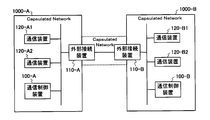
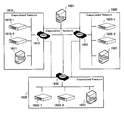
- FIG. 2 is a block diagram illustrating a configuration example of the communication system according to the first embodiment of the present invention.
- the communication system shown in FIG. 2 is a communication system for connecting two virtual environments (for example, the virtual environment 1000-A and the virtual environment 1000-B).
- each of the virtual environments to be connected is a communication control device 100 that controls capsulation communication in the self-virtualized environment and a communication device that is an external connection point of the self-virtualized environment. And an external connection device 110.
- each virtual environment further includes a communication device 120 that performs capsule communication.
- virtualized environment has XX
- the computer system that implements the virtualized environment has XX
- providing two or more virtualization environments means that two or more physically different computer systems each realizing a virtualization environment are provided.
- the virtualization environment 1000-A includes a communication control device 100-A, an external connection device 110-A, a communication device 120-A1, and a communication device 120-A2.
- the virtual environment 1000-B includes a communication control device 100-B, an external connection device 110-B, a communication device 120-B1, and a communication device 120-B2.
- a communication terminal such as a VM may be connected under the communication device 120.
- the communication device 120 and the communication terminal may be constructed on the same physical server.
- the communication device 120 is, for example, a device that performs encapsulation communication using a predetermined virtual network identifier assigned to an interface of the own device in the own virtualization environment. More specifically, the communication device 120 is a virtual switch that, when receiving a packet from a subordinate VM or the like, performs encapsulation using the L2 over L3 encapsulation technology and outputs it to a virtual network in the own virtualization environment. Also good.
- the communication control device 100 may be a network control controller generally called a connection server.
- the communication control apparatus 100 holds terminal information that is information on a communication terminal to be managed as internal information.
- the terminal information is, for example, information indicating where a communication IF of which communication terminal (VM) exists in a switch or gateway (external connection device) included in a virtual environment managed by the terminal information.
- the communication control apparatus 100 holds information that the MAC address MAC1 of the IP address IP1, which is one of the interfaces of the VM1, is on the VS1, as terminal information.
- the communication control device 100 determines from the internal information a communication device (more specifically, a communication destination terminal exists). The interface) as a transfer position, and a function for determining whether communication is possible. Further, when the terminal information of the communication destination terminal exists in the internal information and the transfer position can be specified, the communication control apparatus 100 sets a transfer rule relating to communication with the communication destination terminal to be inquired to the inquiry source communication apparatus. Notice. When the notification is made with respect to a communication destination inquiry, it may be called a communication destination inquiry response.
- the communication control apparatus 100 requests the communication apparatus in the own virtualization environment to search for the communication destination.
- the communication control device 100 When the communication control device 100 is notified of the update (registration, change or deletion) of the terminal information from the communication device in the self-virtualized environment, the communication control device 100 rewrites the internal information and updates the transfer rule to the related communication device. I do.
- the communication control device 100 when registering, changing, or deleting terminal information managed by itself due to the disappearance, transfer, or change of communication availability of virtual machines or communication devices, transfers them to related communication devices. Notify rule updates.
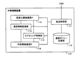
- FIG. 3 is a block diagram illustrating a configuration example of the external connection device 110.
- the external connection device 110 illustrated in FIG. 3 includes a transfer control unit 111, a communication policy storage unit 112, a communication information conversion unit 113, a capsulation control unit 114, a virtual environment communication IF 115, and an external environment communication IF 116. .
- the transfer control unit 111 controls communication within the own device. More specifically, the transfer control unit 111 refers to the communication policy storage unit 112 when the virtual environment communication IF 115 receives a packet, that is, when a packet is received from a communication device in the own virtual environment, Check if the transfer rules that match the packet are maintained. For example, the transfer control unit 111 determines whether or not the transfer rule matches the received packet, the communication information of the packet before encapsulation, that is, the communication information of the internal message, the virtual network identifier attached by the encapsulation, Determine using.
- the communication information is predetermined control information required to deliver the packet to a designated terminal, such as information indicating the destination of the packet and information indicating the transmission source of the packet.
- communication is identified using not only the communication information of the internal message but also the virtual network identifier.
- communication information information used for transfer control in the communication network in the virtual environment
- the information attached to the header portion of the packet after encapsulation is applicable.
- the information on the terminal (communication destination terminal) that actually becomes the final destination of the packet and the information on the terminal (communication source terminal) of the packet are called “communication destination information” and “communication source information”.
- information indicating the destination and the information indicating the transmission source attached to the header portion of the internal message are applicable.
- the communication destination information and the communication source information may be collectively referred to as “communication terminal information”.
- the former may be referred to as destination information and source information in order to distinguish between information indicating the destination and information indicating the source included in the “communication information” and communication destination information and source information.
- a device indicated by transmission destination information may be referred to as a transmission destination device
- a device indicated by transmission source information may be referred to as a transmission source device.
- the transfer control unit 111 performs transfer control to the external environment when a matching transfer rule exists as a result of the search for the transfer rule and the output to the external environment communication IF 116 is indicated by the transfer rule. .
- the transfer control unit 111 causes the communication information conversion unit 113 to rewrite the transmission source information of the received packet with information indicating the own device, and the transmission destination information is information indicating another external connection device.
- the rewritten packet is transferred to the external environment communication IF 116 and requested to be sent to the external environment.
- the transfer control unit 111 determines that the communication destination information of the packet and the virtual network if the inquiry about the communication destination for the received packet is within the specified number of times. Using the identifier, the communication control apparatus 100 in the self-virtualized environment is inquired about the communication destination. Note that the transfer control unit 111 may also use communication source information.
- the designated number of inquiries may be a value determined by the user or system designer, for example, and may include zero. Further, the designated number of times of inquiry may be a value that varies based on a tendency by measuring statistics of the actual number of times of inquiry.
- the transfer control unit 111 discards the received packet.
- the transfer control unit 111 When the external environment communication IF 116 receives a packet, that is, when a packet is received from the external environment side, the transfer control unit 111 refers to the communication policy storage unit 112 and holds a transfer rule that matches the received packet. Check if it is. The transfer control unit 111 also uses a communication destination information and a virtual network identifier attached to the packet to determine whether or not the transfer rule matches the received packet even for the packet received from the external environment. What is necessary is just to judge.
- the transfer control unit 111 if the transfer rule that matches and the output to the virtual environment communication IF 115 is indicated by the transfer rule, Perform transfer control.
- the transfer control unit 111 first specifies the transfer position of the received packet based on the found transfer rule as transfer control into the self-virtualized environment. Then, the transfer control unit 111 causes the communication information conversion unit 113 to rewrite the transmission source information of the received packet with information indicating its own device, and also rewrites the transmission destination information with information indicating the specified transfer position. Then, the rewritten packet is transferred to the virtual environment communication IF 115 and requested to be sent to the own virtual environment.
- the transfer control unit 111 determines whether the internal message of the received packet is a terminal information update message.
- the transfer control unit 111 notifies the communication control apparatus 100 in the own virtualization environment of the terminal information update (addition). For example, as the terminal information, the transfer control unit 111 notifies that the terminal indicated by the terminal information update message is under the external connection device 110 (more specifically, that the terminal is under the external environment communication IF 116). May be. As a result, the internal information of the communication control apparatus 100 in the self-virtualized environment is updated.
- the transfer control unit 111 finds that there is no matching transfer rule as a result of the search for the transfer rule, and the inquiry of the communication destination for the received packet is within the specified number of times, or the terminal information to the communication control device 100 If the update notification is received, an inquiry about the communication destination of the received packet is made to the communication control apparatus 100 in the own virtualization environment.
- the transfer control unit 111 discards the received packet.
- the transfer control unit 111 when requested to search for a communication destination from the communication control device 100 in the self-virtualized environment, creates a search message for the other external connection device 110 in the external environment. Further, the transfer control unit 111 acquires a virtual network identifier to be searched, passes it to the capsuling control unit 114 together with the created search message, and requests capsuling and transfer to the external environment communication IF 116.
- a method for acquiring the search target virtual network identifier for example, there is a method of acquiring from a search request.
- a method of acquiring from a search request referring to virtual network information included in domain information obtained when self-virtualized environment information is obtained when a search request is received, a virtual network identifier with which the self-device can communicate is obtained. A method is mentioned.
- the communication control apparatus 100 uses a domain information for an arbitrary group of virtual machines and communication apparatuses in its own virtualized environment to communicate between virtual machines, between communication apparatuses, and between virtual machines and communication apparatuses. May be managed.
- the domain information may be, for example, information indicating which range of virtual machines and virtual network environments can be handled, or information indicating a unit of a node associated with a setting to be connectable.
- the communication control apparatus 100 for each domain (more specifically, a computer group that configures an arbitrary virtual network) created in the virtual environment, a domain ID, a virtual network identifier as virtual network information, and Self-virtualized environment information including domain information including information associated with port information and communication permitted by the domain (communication between different domains, which domain is permitted, etc.) You may hold as one of these.
- the communication control apparatus 100 may hold a connection rule, virtual network information to which the connection rule is applied, and information indicating a node unit in association with each other without using a domain ID or the like.
- the search message includes information on the communication terminal to be searched.
- An example of the search message may use a message format for requesting a search for a communication destination from the communication control apparatus 100.
- a node search packet format of an existing terminal discovery protocol such as ARP (Address Resolution Protocol) or ICMP (Internet Control Message Protocol) may be used.
- the transfer control unit 111 When the transfer control unit 111 is notified of the update of the transfer rule from the communication control device 100 in the self-virtualized environment, the transfer control unit 111 registers, deletes or deletes the corresponding transfer rule from the communication policy storage unit 112 according to the instruction content. Make a change. In addition, when the notified content relates to registration, deletion, or change of terminal information, the transfer control unit 111 creates a terminal information update message for the other external connection device 110 in the external environment. In addition, the transfer control unit 111 acquires the virtual network identifier of the virtual network to which the own device belongs, passes it to the encapsulation control unit 114 together with the created terminal information update message, and requests the encapsulation and transfer to the external environment communication IF 116. .
- a method for acquiring the virtual network identifier of the virtual network to which the own device belongs there is a method of acquiring from the domain information or virtual network information obtained when acquiring the own virtualization environment information at the time of update notification or the like.
- the terminal information update message includes terminal information related to the communication terminal to be changed. Further, the terminal information update message may further include information indicating an operation instruction for the terminal information (for example, registration, change or deletion of a transfer rule related to the terminal indicated by the terminal information).
- An example of the terminal information update message may use a transfer rule update notification format from the communication control device 100.
- a node response packet format of an existing terminal discovery protocol such as ARP or ICMP may be used.
- the communication policy storage unit 112 stores the transfer rule notified from the communication control device 100 in accordance with the control from the transfer control unit 111.
- the transfer rule stored in the communication policy storage unit 112 may be, for example, information in which information indicating application conditions is associated with information indicating an execution method such as how to process and output.
- the transfer rule includes terminal information including information for identifying a communication terminal and a transfer position (location of the terminal) of a packet addressed to the terminal, and a method for rewriting information on a received packet when transferring to the transfer position. And information including information such as a capsule method.
- the information indicating the application condition and the information specifying the communication terminal include not only the packet communication destination information and the communication source information but also the virtual network identifier.
- Examples of information indicating application conditions include whether or not the capsule is encapsulated, a pair of virtual network identifier and communication destination information when encapsulated, communication source information, communication information, and a combination thereof. Can be mentioned.
- Examples of information indicating the execution method include an encapsulation command or a decapsulation command, a virtual network identifier acquisition method at the time of encapsulation, information indicating a communication information rewriting method, information to the communication control device 100 The presence / absence of notification and a combination thereof may be mentioned.
- the communication information conversion unit 113 converts the communication information of the designated packet in response to a request from the transfer control unit 111.
- the encapsulation control unit 114 performs encapsulation and decoupling of the designated packet in response to a request from the transfer control unit 111. For example, in response to a request from the transfer control unit 111, the encapsulation control unit 114 performs encapsulation on a control message such as a search message or a terminal information update message, or encapsulates the control packet received from the external environment. For example, decapsulation is performed. In addition, for example, the encapsulation control unit 114 can perform encapsulation or decapsulation for realizing communication with a subordinate terminal for a designated packet in response to a request from the transfer control unit 111. .
- the virtual environment communication IF 115 is an interface serving as a communication connection point on the own virtual environment side.
- the virtual environment communication IF 115 is connected to a communication network in the own virtual environment, and receives (receives), for example, a packet transmitted from the communication device 120 in the own virtual environment from the communication network. Also, the virtual environment communication IF 115 outputs (transmits), for example, a packet addressed to the communication device 120 in the own virtual environment on the communication network.
- the virtualization environment communication IF 115 notifies the transfer control unit 111 of the fact.
- the external environment communication IF 116 is an interface serving as a communication connection point on the external environment side.
- the external environment communication IF 116 is connected to a communication network in the external environment.
- the external environment communication IF 116 receives (receives) a packet transmitted from another external connection device 110 in the external environment from the communication network.
- the external environment communication IF 116 outputs (transmits), for example, a packet addressed to another external connection device 110 in the external environment to the communication network.
- the external environment communication IF 116 notifies the transfer control unit 111 to that effect.
- the transfer control unit 111, the communication information conversion unit 113, and the encapsulation control unit 114 are realized by an information processing apparatus such as a CPU that operates according to a program stored in a storage unit, for example.
- the communication policy storage unit 112 is realized by a storage device, for example.
- the virtual environment communication IF 115 and the external environment communication IF 116 are realized by a data input / output device that inputs and outputs data via a network such as a network card, for example.
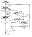
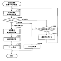
- FIG. 4 to 7 are flowcharts showing an example of the operation of the external connection device of the present embodiment.
- FIG. 4 is a flowchart showing an example of the operation at the time of packet reception from the self-virtualization environment side.
- FIG. 5 is a flowchart illustrating an example of an operation at the time of packet reception from the external environment (cooperative virtualization environment) side.
- FIG. 6 is a flowchart illustrating an example of an operation when a communication destination search request is received from the communication control apparatus 100 in the self-virtualized environment.
- FIG. 7 is a flowchart illustrating an example of an operation when receiving a transfer rule update notification from the communication control apparatus 100 in the self-virtualized environment.
- the flowchart shown in FIG. 4 starts when the virtual environment communication IF 115 receives the packet. At this time, the virtualization environment communication IF 115 notifies the transfer control unit 111 of reception of the packet.
- the transfer control unit 111 refers to the communication policy storage unit 112 and searches for a transfer rule that matches the received packet (step S101).
- the transfer control unit 111 determines whether the output destination is the external environment communication IF 116 (step S102).
- the transfer control unit 111 controls transfer of the received packet to the external environment. Specifically, the transfer control unit 111 requests the communication information conversion unit 113 to convert the communication information of the received packet. At this time, the transfer control unit 111 rewrites the transmission source information with information indicating its own device (more specifically, its external environment communication IF 116), and the transmission destination information as another external connection device 110 in the external environment. The communication information conversion unit 113 is requested to rewrite the information indicating (more specifically, the external environment communication IF 116).
- the transfer control unit 111 may store, for example, information on the other external connection device 110 in advance, or may acquire the information by making an inquiry to a dedicated configuration tool.
- the communication information conversion unit 113 converts the communication information of the received packet based on the request from the transfer control unit 111 (step S103). In addition, the communication information conversion unit 113 transfers the packet for which the conversion process has been completed to the external environment communication IF 116. The external environment communication IF 116 outputs the packet to the external environment communication network (step S104).
- step S105 determines whether or not the communication destination inquiry for the received packet is within the specified number of times. If it is within the specified number of times (Yes in step S105), the transfer control unit 111 inquires the communication control apparatus 100 about the communication destination of the received packet (step S106).
- step S106 After the inquiry about the communication destination in step S106, when a transfer rule suitable for the received packet is notified as an inquiry response or when the inquiry is terminated due to a timeout or the like, the transfer control unit 111 returns to step S101, Redo transfer control. If there is an inquiry response from the communication control apparatus 100, the transfer control unit 111 may omit step S101 and proceed to the process of step S102 based on the notified transfer rule.
- step S101 when the transfer rule found in step S101 has a pattern other than the above, such as an output destination other than the external environment communication IF 116 (step S102c), a communication destination inquiry for the received packet is designated.
- the transfer control unit 111 discards the received packet (step S107). For example, the transfer control unit 111 may request the virtual environment communication IF 115 to discard the received packet and discard the received packet.
- the external connection device 110 performs the process of the own virtual environment on the packet received by the virtual environment communication IF 115 by being transferred from the communication device in the virtual environment to which the own device belongs. If transfer to the external environment is possible according to the transfer rule notified from the communication control device 100, the transfer can be made toward the external connection device 110 in another virtual environment without decapsulation.
- a virtual network identifier used in each virtualization environment is treated as a unique identifier in the communication system. That is, in the encapsulation communication between virtual environments, the identifier of the virtual network to which the communication destination terminal or the communication source terminal belongs is used as it is. Therefore, the external connection device 110 in the other virtual environment receiving the packet designates it as a communication destination according to the transfer rule in the own virtual environment based on the communication terminal information and the virtual network identifier included in the received packet.
- the packet may be delivered to the received terminal or a device that can be transferred to the terminal.
- the flowchart shown in FIG. 5 starts when the external environment communication IF 116 receives a packet. At this time, the external environment communication IF 116 notifies the transfer control unit 111 of packet reception.
- the transfer control unit 111 When notified of the reception of the packet from the external environment communication IF 116, the transfer control unit 111 refers to the communication policy storage unit 112 and searches for a transfer rule that matches the received packet (step S111).
- the transfer control unit 111 determines whether the output destination is the virtual environment communication IF 115 (step S112).
- the transfer control unit 111 When the output destination is the virtual environment communication IF 115 (a in step S112), the transfer control unit 111 performs transfer control on the received packet into the own virtual environment. Specifically, the transfer control unit 111 requests the communication information conversion unit 113 to convert the communication information of the received packet. At this time, the transfer control unit 111 rewrites the transmission source information of the packet to information indicating its own device (more specifically, its virtual environment communication IF 115), and converts the transmission destination information to the transfer position included in the transfer rule. The communication information conversion unit 113 is requested to rewrite the information to indicate information.
- the communication information conversion unit 113 converts the communication information of the received packet based on the request from the transfer control unit 111 (step S113). Further, the communication information conversion unit 113 transfers the packet for which the conversion process has been completed to the virtual environment communication IF 115.
- the virtual environment communication IF 115 outputs the packet to the communication network of the own virtual environment (step S114).
- step S111 determines whether the received packet is a terminal information update message. It is determined whether or not (step S115).
- step S115 If the received packet is a terminal information update message (Yes in step S115), the transfer control unit 111 updates the terminal information update (registration, registration) to the communication control device 100 in the own virtualization environment based on the terminal information update message. Change or deletion) is notified (step S116). Note that after the terminal information update notification, the process proceeds to step S118.
- step S115 determines whether or not the inquiry about the communication destination for the received packet is within the specified number of times.
- step S117 determines whether or not the inquiry about the communication destination for the received packet is within the specified number of times.
- step S118 the transfer control unit 111 inquires the communication control device 100 of the self-virtualized environment about the communication destination of the received packet. If the transfer rule regarding the packet is notified as an inquiry response after the inquiry about the communication destination, the process proceeds to step S112 based on the notified transfer rule. On the other hand, if the inquiry about the communication destination is terminated due to timeout or the like, the process proceeds to step S119.
- step S119 the transfer control unit 111 determines whether the received packet is a control message. If the received packet is a control message (Yes in step S119), the process proceeds to step S120. On the other hand, if the received message is not a control message (No in step S119), the search is repeated from the search for the transfer rule (return to step S111).
- step S111 if the transfer rule found in step S111 has a pattern other than the above, such as an output destination other than the virtual environment communication IF 115 (step S112c), the process proceeds to step S120.
- step S120 the transfer control unit 111 discards the received packet.
- the transfer control unit 111 determines that the output destination is other than the virtual environment communication IF 115 (step S112c), or the communication destination inquiry for the received packet exceeds the specified number of times. (No in step S117) or, after the received packet is a control message, the communication packet is inquired once (Yes in step S119), and the received packet is discarded.
- the transfer control unit 111 may request the external environment communication IF 116 to discard the received packet and discard the received packet.
- the external connection device 110 automatically responds to a packet received by the external environment communication IF 116 by being transferred from another external connection device 110 outside the virtual environment to which the self device belongs.
- the transfer rule notified from the communication control apparatus 100 in the virtual environment when transfer is possible in the virtual environment, the transfer can be performed toward the transfer position indicated in the transfer rule without decapsulation.
- the flowchart shown in FIG. 6 starts when the external connection apparatus 110 receives a communication destination search request from the communication control apparatus 100 in the self-virtualized environment.
- the transfer control unit 111 When receiving the communication destination search request from the communication control apparatus 100, the transfer control unit 111 creates a search message (step S131). Then, the transfer control unit 111 acquires a virtual network identifier to be searched, passes it to the capsuling control unit 114 together with the created search message, and requests capsuling. For example, the transfer control unit 111 includes the virtual network identifier in a capsuling header part that is a header part newly added by capsuling, sets the transmission source apparatus as its own apparatus, and sets the transmission destination apparatus as an external environment. Requests that another external connection device 110 that is linked to the device creates a encapsulation packet.
- the encapsulation control unit 114 performs the encapsulation of the search message in response to a request from the transfer control unit 111 (step S132). Then, the encapsulation control unit 114 transfers the generated encapsulation packet to the external environment communication IF 116.
- the external environment communication IF 116 outputs the packet to the external environment communication network (step S133).
- a search message for searching for a communication destination terminal outside the virtual environment can be transmitted to another external connection device 110 in the external environment together with the virtual network identifier. Accordingly, in response to a search request from the communication control apparatus 100 in its own virtual environment, the external connection apparatus 110 that is the cooperation destination can make an inquiry about the communication destination to the communication control apparatus 100 in the own virtual environment. it can.
- the flowchart shown in FIG. 7 starts when the external connection apparatus 110 receives a transfer rule update notification from the communication control apparatus 100 in the own virtualization environment.
- the transfer control unit 111 When receiving the transfer rule update notification from the communication control apparatus 100, the transfer control unit 111 registers, changes, or deletes the transfer rule in the communication policy storage unit 112 according to the update content (step S141). Note that the transfer control unit 111 may return an update response to the communication control device 100 if necessary.
- the transfer control unit 111 determines whether or not the update content of the transfer rule is accompanied by the update of terminal information (step S142). For example, the transfer control unit 111 determines that the update of the terminal information is accompanied when the update adds or deletes the transfer rule or changes the information identifying the communication included in the existing transfer rule. May be. In addition, for example, if the update content is a change in transfer position or a change in the encapsulation method, the transfer control unit 111 may determine that the terminal information is not updated.
- the transfer control unit 111 creates a terminal information update message (step S143) when the update content of the transfer rule is accompanied by the update of the terminal information (Yes in step S142). Then, the transfer control unit 111 acquires the virtual network identifier of the virtual network to which the own device belongs, and transfers the virtual network identifier together with the created terminal information update message to the capsuling control unit 114 to request capsuling. For example, the transfer control unit 111 includes the virtual network identifier in a capsuling header portion, and sets the transmission source device as its own device, the transmission destination device as an external environment, and other external connection devices 110 that are linked to the own device. Request that the encapsulation packet be created.
- the encapsulation control unit 114 performs the encapsulation of the terminal information update message in response to a request from the transfer control unit 111 (step S144). Then, the encapsulation control unit 114 transfers the generated encapsulation packet to the external environment communication IF 116.
- the external environment communication IF 116 outputs the encapsulation packet (step S145).
- the transfer control unit 111 may end the process for the notification as it is.
- the terminal information update message of the terminal related to the update content is sent to the other external connection device 110 in the external environment triggered by the transfer rule update notification from the communication control device 100 in the self-virtualized environment. Can be transmitted along with the virtual network identifier.
- the addition or deletion to the communication control device 100 of its own virtual environment is added to the external connection device 110 of the cooperation destination. It can be notified as an update of a subordinate terminal.
- the computer environment shown in FIG. 8 is an example in which a virtual environment 1010 and a virtual environment 1020 are linked.
- the virtual environment 1010 includes a communication control server 1011 (CS1) equipped with a communication control device 100 that controls capsuling communication in the virtual environment 1010, and an external connection device that serves as a communication connection point between the virtual environment and the outside. 110, a gateway device 1012 (GW1) on which 110 is mounted, and a plurality of VM servers (VM server 1013-1 and VM server 1013-2) that execute VMs.
- CS1 communication control server 1011
- GW1 gateway device 1012
- VM server 1013-1 and VM server 1013-2 a plurality of VM servers
- the virtual environment 1020 includes a communication control server 1021 (CS2) equipped with the communication control apparatus 100 that controls capsuling communication in the virtual environment 1020, and an external communication connection point between the own virtual environment and the outside.
- a gateway apparatus 1022 (GW2) on which the connection apparatus 110 is mounted and a plurality of VM servers (VM server 1023-1 and VM server 1023-2) for executing the VM are provided.
- the virtualization environment 1010 and the virtualization environment 1020 are connected via the GW1 and the GW2.
- VM1 which is one of the communication terminals included in the virtual environment 1010 and VS1 which is one of the virtual switches are both executed on the VM server 1013-1.
- VM2 which is one of the communication terminals included in the virtual environment 1020 and VS2 which is one of the virtual switches are both executed on the VM server 1023-2.
- each of CS1 and CS2 acquires the position of the VM in the self-virtualized environment as terminal information from a setting value or the like or by learning.
- IP address is held as one piece of information for identifying a terminal included in the terminal information.
- multilayer protocol information for example, MAC address information etc.
- address information is an L3 protocol having an L2 frame having an ID space expanded by overlay technology, such as VXLAN and NvGRE, in the encapsulation communication within each virtualization environment and the encapsulation communication between the virtualization environments.
- L3 protocol using an IP address is used, but the protocol used in the encapsulation communication is not limited to the above.
- the protocol of the capsuling communication in each virtual environment and the capsuling communication between the virtual environments may be different.
- FIG. 9 is a sequence diagram showing an example of the communication terminal discovery operation of the present embodiment.
- FIG. 10 is a sequence diagram illustrating an example of a communication transmission operation in the present embodiment.
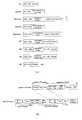
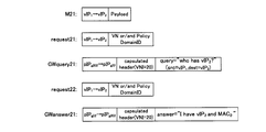
- FIG. 11A is an explanatory diagram schematically illustrating an example of a packet used in the examples illustrated in FIGS. 9 and 10.
- VM1 generates a packet addressed to VM2 and transmits it to VS1 (M1 in the figure).
- vIP 2 represents the IP address of the VM2.
- VS1 Since VS1 does not hold a transfer rule that matches the received packet, it queries CS1 for the communication destination (request1 in the figure).
- CS1 receives the inquiry of the communication destination, but cannot resolve the address of VM2 that is the destination terminal, and therefore requests GW1 to search for the communication destination (query1 in the figure).
- GW1 Upon receiving a communication destination search request from CS1, GW1 creates a search message, further performs encapsulation, and transmits it to the other linked GW2 (GWquery1 in the figure).
- the search message includes at least the VIP 2 that is the IP address of the VM 2 as information on the terminal to be searched.
- the GW 1 acquires the virtual network identifier to be searched and includes it in the capsuling header part, and uses the pIP g1 that is the IP address of the GW 1 that is the own device as the source information, and is linked as destination information.
- the search message is encapsulated using pIP g2 , which is the IP address of GW2.
- GW2 has not learned anything about VM2 at this time.
- CS2 has already acquired terminal information related to VM2, for example, from a setting value at the time of startup.
- the GW 2 When the GW 2 receives the search message encapsulation packet from the cooperation destination GW 1, there is no transfer rule that matches the received packet, the received packet is not a terminal information update message, and a communication destination inquiry about the received packet is received. Since it is within the specified number of times (in this example, once), the communication destination of the received packet (here, the communication destination to be searched) is inquired of CS2 (request2 in the figure).
- CS2 Since CS2 knows the location of VM2, as a response to the inquiry, CS2 sends a transfer rule update notification indicating VS2 IP address VIP s2 as a transfer location to GW2 for the packet addressed to VM2 ( Answer1 in the figure).
- the GW 2 When the GW 2 receives the transfer rule update notification from the CS 2, the GW 2 updates the transfer rule in the communication policy storage unit 112 based on the notified update content. Further, since the update is an update accompanied by the addition of terminal information related to VM2, the GW2 creates a terminal information update message, performs encapsulation, and transmits the message to the GW1 (GW answer 1 in the figure). For example, the GW 2 may create a terminal information update message including terminal information indicating that the VIP 2 is under the control of the GW 2 that is the own device as the terminal information regarding the VM 2 .
- GW2 acquires the virtual network identifier of the virtual network to which the own device belongs, includes the acquired virtual network identifier in the encapsulation header portion, and is the IP address of GW2 that is the own device as transmission source information.
- the terminal information update message is encapsulated using pIP g1 , which is the IP address of the other GW 1 linked as transmission destination information.
- the encapsulation packet of the terminal information update message is transmitted to the other GW1.
- the GW1 When the GW1 receives the encapsulation packet of the terminal information update message from the cooperation destination GW2, there is no transfer rule that matches the received packet, and the received packet is a terminal information update message. Based on this, CS1 is notified of the update of terminal information related to VM2 (answer2 in the figure). For example, the GW 1 sends a terminal information update (registration) notification to the CS 1 indicating that the terminal specified by the terminal information included in the received terminal information update message is a terminal under the GW 1 as its own device. Also good. At this time, the GW 1 notifies the virtual network identifier notified from the GW 2 as it is as the virtual network identifier to which the VM 2 belongs.
- CS1 updates internal information according to the notified update content.
- CS1 receives the update notification of the terminal information and transmits a response (transfer rule update notification) to the communication destination inquiry from VS1 that has been held, or is applied to the packet addressed to VM2 to GW1.
- a transfer rule update notification may be transmitted.
- the CS1 of the virtual environment 1010 can discover the VM2 existing in the other virtual environment 1020 by the cooperation of the GW1 and the GW2. Therefore, it can be seen that CS1 only has to transfer a packet addressed to VM2 to GW1.
- a central management server or the like is not required. Even if there are a plurality of other external connection devices 110 that are linked, once the transfer destination is learned, communication between the virtual environments is not distributed processing by multicast or multiple unicasts, Since it can be realized by unicast communication with a specific GW, communication is optimized.
- the GW 1 inquires the CS 1 about the communication destination of the received packet that is the encapsulation packet of the terminal information update message from the GW 2.
- CS 1 receives the inquiry about the communication destination, but since the packet is a terminal information update message and corresponds to a message addressed to the communication control apparatus 100, CS 1 replies that the transfer rule is not set. Then, the GW 1 that has received the notification that the communication rule is not set from the CS 1 discards the packet because the packet is a control message.
- the VS1 and the GW1 may update their own transfer rules according to the update contents.
- VM1 generates a packet addressed to VM2 and transmits it to VS1 (M1 in the figure). Since VS1 does not hold a transfer rule that matches the received packet, CS1 makes an inquiry about the communication destination (request1 in the figure).
- CS1 Since CS1 has learned GW1 as the transfer position of the packet addressed to VM2, it returns a transfer rule update notification indicating GW1 as the transfer position of the received packet (answer3 in the figure).
- VS1 receives the transfer rule update notification from CS1 and updates the transfer rule held by itself. Then, VS1 performs encapsulation of the received packet according to the updated transfer rule, and transfers it to GW1 (M2 in the figure). At this time, the VS1 registers the virtual network identifier set in the IF with the VM1 in the encapsulation header part.
- the GW1 When the GW1 receives the encapsulation packet from the VS1 via the virtual environment communication IF 115, the GW1 refers to the communication policy storage unit 112 and extracts a transfer rule that matches the received packet. In this example, a transfer rule whose output destination is the external environment communication IF 116 is extracted. In accordance with the extracted transfer rule, GW1 rewrites the source information of the received packet to pIP g1 that is the IP address of GW1 that is the own device, and pIP that is the IP address of the other GW2 that cooperates with the destination information Rewrite to g2 . Then, the GW 1 outputs the rewritten packet to the external environment communication network from the external environment communication IF 116 (M3 in the figure).
- the packet is transferred from GW1 to GW2 according to the communication information of the packet.
- the external environment communication IF 116 receives the packet.
- the GW 2 refers to the communication policy storage unit 112 and extracts a transfer rule that matches the received packet.
- a transfer rule whose output destination is the virtualization environment communication IF 115 and whose transfer position is vIP s2 is extracted.
- GW2 according extracted forwarding rules, rewrites the source information of the received packet to pIP g2 is the IP address of the GW2 is its own device, and rewrites the vIP s2 is a transfer position indicating the destination information forwarding rules .
- the GW 2 outputs the rewritten packet to the communication network of the virtual environment 1020 from the virtual environment communication IF 115 (M4 in the figure).
- the packet is transferred from the GW 2 to the VS 2 according to the communication information of the packet.
- VS2 When VS2 receives the packet, it performs decapsulation (decapsulation) according to the transfer rule held by itself, and transfers it to VM2 (M5 in the figure).
- packets from VM1 to VM2 are handled as belonging to one large virtual network and can be communicated using the encapsulation communication of each virtual environment.
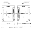
- FIG. 11B is an explanatory diagram showing an example of a packet format of the capsule communication in this example.
- the example shown in FIG. 11B is an example of a packet format when the encapsulation communication protocol is the VXLAN protocol.
- “original L3 frame” is an example of a packet format applied to M1 and M5 in the above example
- “new L3 frame” is applied to M2 to M4 in the above example. It is an example of a packet format.
- the VM 1 may send a message addressed to the VM 2 to the VS 1 using “original L3 Frame”.
- the IP address and MAC address of VM1 are registered in “IP DA” and “MAC DA” of “original L3 frame”.
- the IP address and the MAC address of the VM 2 are registered in “IP SA” and “MAC SA” of “original L3 Frame”.
- the VS 1 when receiving such a packet from the VM 1, the VS 1 indicates a virtual network identifier (VNI) set in an interface with the VM 1, its own IP address and MAC address, and a transfer position.
- the packet may be converted (encapsulated) into “new L3 Frame” based on the IP address and the MAC address.
- IP DA” and “MAC DA” of “original L3 Frame” are registered in “IP DA 1 ” and “MAC DA 1 ” of “new L3 Frame”.
- IP SA” and “MAC SA” of “original L3 Frame” are registered in “IP SA 1 ” and “MAC SA 1 ” of “new L3 Frame”.
- the VNI set in the interface with the own (VS1) VM1 is registered.
- the IP address and MAC address of itself (VS1) are registered in “IP DA 2 ” and “MAC DA 2 ” of “new L3 Frame”.
- IP SA 2 ” and “MAC SA 2 ” of “new L3 Frame” the IP address and MAC address of the interface that is the transfer position are registered.
- part of the communication terminal information (“IP DA” and “IP SA” of “original L3 Frame”) is included in the capsuling header part. The information may be handled as communication terminal information.
- IP DA and “IP SA” of “original L3 Frame”
- the information may be handled as communication terminal information.
- the above is an example in which VM1 and VM2 belong to the same VNI virtual network.
- the packet format is not limited to this.
- FIG. 8 shows an example in which the virtual environment is connected on a one-to-one basis
- the connection form of the virtual environment is not limited to one-to-one.
- communication information destination information and transmission source information
- a mode in which virtual environments are connected to each other is also possible.
- each virtual environment is an external connection device serving as an external connection point between the communication control server in which the communication control device 100 that controls communication in the own virtual environment is mounted and another virtual environment.
- a gateway device on which 110 is mounted includes a communication control server 1101 (CS10), a gateway device 1102-1 (GW 101) serving as an external connection point between the virtualization environment 1110, and a gateway serving as an external connection point between the virtualization environment 1120. It includes at least a device 1102-2 (GW102) and a gateway device 1102-9 (GW109) serving as an external connection point with the virtual environment 1190.
- the virtual environment 1110 has at least a communication control server 1111 (CS11) and a gateway device 1112 (GW11) serving as an external connection point with the virtual environment 1100.
- the virtual environment 1120 includes at least a communication control server 1121 (CS12) and a gateway device 1122 (GW 12) serving as an external connection point with the virtual environment 1100.
- the virtual environment 1190 includes at least a communication control server 1191 (CS 19) and a gateway device 1192 (GW 19) serving as an external connection point with the virtual environment 1100.
- GW 101 and GW 11 are connected via an external environment communication network
- GW 102 and GW 12 are connected via an external environment communication network
- GW 109 and GW 19 are connected via an external environment communication network.
- the CS 10 is another virtualization environment (a virtualization environment 1110, a virtualization environment 1120,..., A virtualization environment 1190) to be linked.
- a search request can be made to GW101, GW102,.
- the search message encapsulating packet may be transmitted to GW12 for GW102, GW19 for GW109, and the like. At this time, the address information of the gateway device as the transmission destination may be set in advance.
- communication between virtualization environments is performed using the conversion processing of transmission destination information and transmission source information via an external connection device that is an external connection point of each virtualization environment. Since packets are transferred, one huge virtual network connecting independent virtual environments can be constructed. Thereby, the user can easily construct a huge pseudo-virtualized environment formed by connecting virtualized environments at different bases. Further, in this pseudo-virtualized environment, since the virtual network identifier used by each virtualized environment is shared, control such as ID conversion inside and outside the virtualized environment and two types of ID management for the ID conversion is required. And not.
- the communication control device 100 is arranged in each virtual environment.
- the search phase is the same as in the normal network search. For discovery and communication. Therefore, it is not necessary to provide a plurality of central management servers for load distribution, and synchronization processing and consistency processing between the central management servers are not necessary, so that network restrictions for building a virtual environment can be relaxed.
- the management server (communication control device 100) that manages the connection.
- control of the central management server is important. That is, when trying to create a huge virtual environment, centralized processing of the central management server becomes a problem. For this reason, load balancing and redundancy techniques are usually used for the central management server.
- each central management server needs to have high functionality such as data synchronization, consistency maintenance, and management area control.
- in order to realize a huge virtual network by connecting the virtualization environments by the encapsulation communication by each external connection device while maintaining independent control in the virtualization environment with the external connection device as a boundary. It is possible to prevent the management server from becoming highly functional.
- the virtual networks in each virtual environment can operate, and thus communication between VMs in the virtual environment can be maintained.
- each virtual environment has its own management server, so that communication unrelated to other virtual environments can be closed and controlled in its own environment.
- This characteristic is particularly effective in the case of a network in which the virtual environments are unstable or weak in quality, for example, in the case of inter-organization cooperation or inter-base cooperation.
- FIG. 13 is a block diagram illustrating a configuration example of the external connection device according to the first modification of the present embodiment.
- the external connection device 210 shown in FIG. 13 is greatly different from the external connection device 110 shown in FIG. 3 in that an external connection setting storage unit 217 is further provided.
- the external connection setting storage unit 217 stores packet transfer restrictions, which are restrictions related to packet transfer between the own virtualization environment and another virtualization environment.
- the external connection setting storage unit 217 is realized by a storage device, for example.
- Other means transfer control unit 211, communication policy storage unit 212, communication information conversion unit 213, capsuling control unit 214, virtualization environment communication IF 215, and external environment communication IF 216) are the transfer in the configuration example shown in FIG.
- the control unit 111, the communication policy storage unit 112, the communication information conversion unit 113, the encapsulation control unit 114, the virtual environment communication IF 115, and the external environment communication IF 116 may be basically the same.
- the transfer control unit 211 has the following functions in addition to the functions of the transfer control unit 111 described above. That is, the transfer control unit 211 refers to the packet transfer restriction from the external connection setting storage unit 217 when transmitting / receiving a packet in the external environment communication IF 216 that is a connection point with another virtualization environment, and determines whether transmission / reception is permitted. judge. The transfer control unit 211 instructs transmission / reception of a packet only when it is permitted. If not allowed, discard the packet.
- An example of a packet transfer constraint is information on allowed virtual network identifiers.
- the packet transfer constraint may be information on a set of permitted virtual network identifiers and connection ports.
- the packet transfer constraint may be information on a set of permitted virtual network identifiers and transmission destination devices.
- FIGS. 14 to 17 are flowcharts illustrating an example of the operation of the external connection device 210 according to the first modification of the first embodiment.
- FIG. 14 is a flowchart showing an example of the operation at the time of packet reception from the self-virtualized environment side.
- FIG. 15 is a flowchart illustrating an example of an operation when a packet is received from the external environment (cooperative virtualization environment) side.
- FIG. 16 is a flowchart illustrating an example of an operation at the time of receiving a communication destination search request from the communication control apparatus 100 in the self-virtualized environment.
- FIG. 17 is a flowchart illustrating an example of an operation when receiving a transfer rule update notification from the communication control apparatus 100 in the self-virtualized environment.
- step S203 the operation when the external connection device 210 receives a packet from the self-virtualized environment side will be described with reference to FIG. This operation is largely different from the operation shown in FIG. 4 in that step S203 is added.
- the transfer control unit 211 is a case where the virtual environment communication IF 215 receives a packet, the transfer policy that matches the received packet exists in the communication policy storage unit 212, and the output destination is the external environment communication IF 216. In the case (a in step S202), the process proceeds to step S203.
- the transfer control unit 211 refers to the packet transfer restriction in the external connection setting storage unit 217, and determines whether the received packet can be transferred to the external environment. At this time, the transfer control unit 211 determines whether transfer is possible by referring to the packet transfer constraint based on at least the virtual network identifier included in the capsuling header part of the received packet. Note that the transfer control unit 211 determines whether or not transfer is possible by adding information other than the virtual network identifier used for packet transfer restriction, such as a connection port and transmission destination information, if necessary.
- step S203 If the packet transfer is permitted (Yes in step S203), the transfer control unit 211 continues the packet transfer process (proceeds to step S204). If packet transfer is not permitted (No in step S203), the transfer control unit 211 discards the received packet from the virtual environment communication IF 215 (proceeds to step S208).
- the transfer control unit 211 When the external environment communication IF 216 receives a packet, the transfer control unit 211 first refers to the packet transfer restriction from the external connection setting storage unit 217 to determine whether the received packet can be transferred to the own virtualization environment ( Step S211). At this time, the transfer control unit 211 determines whether transfer is possible by referring to the packet transfer constraint based on at least the virtual network identifier included in the capsuling header part of the received packet. Note that the transfer control unit 211 determines whether or not transfer is possible by adding information other than the virtual network identifier used for packet transfer restriction, such as a connection port and transmission destination information, if necessary.
- step S211 If the packet transfer is permitted (Yes in step S211), the transfer control unit 211 continues the packet transfer process (proceeds to step S212). When packet transfer is not permitted (No in step S211), the transfer control unit 211 discards the received packet from the external environment communication IF 216 (proceeds to step S221).
- step S231 the operation when the external connection device 210 receives a communication destination search request from the communication control device 100 of the self-virtualized environment. This operation is largely different from the operation shown in FIG. 6 in that step S231 is added.
- the transfer control unit 211 When the transfer control unit 211 receives a request for searching for a communication destination from the communication control device 100 in its own virtualization environment, the transfer control unit 211 first refers to the packet transfer constraint from the external connection setting storage unit 217 and searches for a search message based on the request. It is determined whether or not transfer is permitted (step S231). The transfer control unit 211 determines whether or not the transfer of the message using the virtual network identifier is permitted with reference to the packet transfer restriction based on at least the virtual network identifier that is the search range received at the time of the search request. May be.
- step S231 If transfer of the search message based on the request is permitted (Yes in step S231), the transfer control unit 211 continues the search process (proceeds to step S232). On the other hand, if it is not permitted (No in step S231), the transfer control unit 211 ends the process for the request as it is.
- step S243 the operation when the external connection device 210 receives a transfer rule update notification from the communication control device 100 in the self-virtualized environment. This operation is largely different from the operation shown in FIG. 7 in that step S243 is added.
- step S242 when the transfer control unit 211 receives a transfer rule update notification from the communication control device 100 in its own virtualization environment, and the update content of the transfer rule is accompanied by the update of the terminal information (in step S242). Yes), the process proceeds to step S243.
- step S243 the transfer control unit 211 refers to the packet transfer restriction in the external connection setting storage unit 217, and determines whether the virtual network identifier applied to the updated terminal information is within the update notification range in the external environment. That is, it is determined whether or not the virtual network is transferable.
- step S243 the transfer control unit 211 continues the transfer process of the terminal information update message to the target external environment communication IF 216 (proceeds to step S244). If it is out of the notification range of update (No in step S243), the transfer control unit 211 ends the transfer rule update processing as it is.
- the computer environment shown in FIG. 18 is an example in which a plurality of virtualization environments (a virtualization environment 1210, a virtualization environment 1220,..., A virtualization environment 1290) are linked with a virtualization environment 1200 as a center.
- each virtual environment is an external connection device serving as an external connection point between the communication control server in which the communication control device 100 that controls communication in the own virtual environment is mounted and another virtual environment.
- a gateway device in which 210 is mounted.
- the virtual environment 1200 includes a communication control server 1201 (CS20), a gateway device 1202-1 (GW 201) serving as an external connection point between the virtual environment 1210, and a gateway serving as an external connection point between the virtual environment 1220. It includes at least a device 1202-2 (GW 202) and a gateway device 1202-9 (GW 209) serving as an external connection point with the virtual environment 1290.
- CS20 communication control server 1201
- GW 201 gateway device 1202-1
- GW 209 serving as an external connection point between the virtual environment 1220.
- GW 209 serving as an external connection point with the virtual environment 1290.
- the virtualization environment 1210 includes a communication control server 1211 (CS21) and a gateway device 1212 (GW21) serving as an external connection point with the virtualization environment 1200.
- the virtualization environment 1220 includes a communication control server 1221 (CS22) and a gateway device 1222 (GW22) that is an external connection point with the virtualization environment 1200.
- the virtual environment 1290 includes a communication control server 1291 (CS 29) and a gateway device 1292 (GW 29) serving as an external connection point with the virtual environment 1200.
- GW201 and GW21 are connected by an external environment network
- GW202 and GW22 are connected by an external environment network
- GW209 and GW29 are connected by an external environment network.
- a virtual switch (VS20) serving as a communication connection point with the capsuling communication in the own virtual environment is operating.
- VS22 serving as a communication connection point with the capsuling communication in the own virtual environment
- VM1 and VM2 may belong to virtual networks having different identifiers.
- packet transfer restriction that permits communication between the gateway devices (GW 202 and GW 22) connecting the virtual environment 1200 and the virtual environment 1220 with the virtual network to which the VM 1 and VM 2 belong. Can be registered.
- FIG. 19 is a sequence diagram showing an example of the communication terminal finding operation in this modification.
- FIG. 20 is an explanatory diagram schematically showing an example of a packet used in this example.
- VM1 has transferred a packet addressed to VM2 to VS20 (M21 in the figure).
- the VS 20 Since there is no transfer rule that matches the received packet, the VS 20 makes an inquiry to the CS 20 about the communication destination VM 2 (request 21 in the figure).
- the CS 20 receives the inquiry about the communication destination, but cannot resolve the address of the VM 2 that is the destination terminal, so the GW 201 to GW 209 that are external connection points with other virtualization environments included in the virtualization environment are informed of the communication destination.
- a search request is made (request 21-1 to request 21-2 in the figure).
- the GW 202 when receiving a communication destination search request, refers to the external connection setting storage unit 217 and determines that the virtual network identifier to be searched by the request is transferable. Accordingly, the GW 202 creates a search message, performs encapsulation, and transmits the message to the other linked external connection device GW 22 (GW query 21 in the figure).
- the search message includes at least the VIP 2 that is the IP address of the VM 2 as the terminal information of the VM 2 to be searched.
- the search message is encapsulated using pIP g22 which is the IP address of GW22 which is the external connection device.
- the encapsulating packet of the search message is transmitted to the linked GW 22.
- VNI virtual network identifier
- the GW 22 determines whether or not the received packet is a terminal information update message on the assumption that the transfer rule regarding the VM 2 is not held at this time. Since the received packet is a message (search message) that is different from the terminal information update message, the CS 22 is inquired of the communication destination VM2 on the condition that the received packet is within the specified number of times (this time is 1 time). (Request 22 in the figure). Note that a search target terminal is set as the communication destination of the search message in this example.
- the CS 22 Since the CS 22 knows the position of the VM 2, as a response to the inquiry, the CS 22 transmits a transfer rule update notification indicating the IP address of the VS 22 as the transfer position to the GW 22 for the packet addressed to the VM 2 (FIG. Answer 21).
- the GW 22 When the GW 22 receives the transfer rule update notification from the CS 22, the GW 22 updates the information in the communication policy storage unit 212 based on the notified transfer rule.
- the GW 22 adds the transfer rule of the packet whose destination is the VM2 as the notified update contents of the transfer rule, and involves updating the terminal information related to the VM2, so refer to the external connection setting storage unit 217. Then, it is determined whether or not the terminal information can be transferred.
- the GW 22 includes the acquired virtual network identifier in the encapsulation header part in the encapsulation process, sets the transmission source device as the GW 22 (pIP g22 ) as the own device, and sets the transmission destination information as the other GW 202 (pIP g202 ). . Thereby, the encapsulation packet of the terminal information update message is transmitted to the other GW 202.
- VNI virtual network identifier
- the GW 202 since there is no transfer rule that matches the received packet and the received packet is a terminal information update message, the GW 202 notifies the CS 20 of the update of the terminal information related to the VM2 (answer 22 in the figure). . At this time, the GW 202 may notify the CS 20 that the VM 2 is a terminal under the external environment communication IF 216 of the GW 202.
- the CS 20 that has received the update notification of the terminal information, based on the notified terminal information, specifies information to be updated (such as a set of VM2 address information and virtual network identifier), and a transfer position of the packet addressed to the terminal
- the source information (address information of the GW 202 in this example) is stored in association with the terminal information of the internal information.
- the CS 20 of the virtual environment 1200 can discover the VM 2 existing in the virtual environment 1220 to be linked through the GW 202 and the GW 22. Therefore, it is understood that the packet addressed to VM2 only needs to be transferred from GW 202 to GW 22.
- the GW 202 continues processing the received packet even after the terminal information update notification. As a result of inquiring the communication destination of the received packet to the CS 20, the processing is not set, and since the received message is a control message, the received packet is discarded.
- the communication transmission flow after the terminal discovery is basically the same as the flow shown in FIG. 9 and FIG. However, the difference is that a determination of whether transfer is possible for a message received by the GW 202 is added.
- the effect of this modification is that, in addition to the effect of the first embodiment described above, the search range of communication destinations can be narrowed. This is because, when the external connection device 210 transfers a packet, it is possible to determine whether or not transfer processing is permitted, thereby providing a filtering action.
- the search range of VM2 can be limited to between GW202 and GW22, and an extra search message can be prevented from being sent between GW201 and GW21 or between GW209 and GW29. .
- each external connection device learns connections between virtual environments in an external environment.
- FIG. 21 is a block diagram illustrating a configuration example of the external connection device according to the second embodiment.
- the external connection device 310 shown in FIG. 21 is greatly different from the external connection device 110 of the first embodiment shown in FIG. 3 in that it further includes an external environment communication policy storage unit 318.
- the former is referred to as a “virtualized environment communication policy storage unit” so that the communication policy storage unit 112 and the like so far can be easily distinguished from the external environment communication policy storage unit 318.
- the external environment communication policy storage unit 318 stores an external environment transfer rule that is a transfer rule applied to communication with the external environment in the external connection device.
- the external environment communication policy storage unit 318 may have an area for temporarily storing a provisional external environment transfer rule before being confirmed in addition to the established external environment transfer rule.
- the external environment transfer rule is a transfer rule applied to a packet addressed to the external environment.
- information indicating an external connection device in another virtual environment is registered as information indicating a transfer position of a packet to which the rule is applied.
- the external connection device 310 holds and learns the external environment transfer rules, thereby optimizing the transfer of packets addressed to other external connection devices in the external environment.
- Transfer control unit 311, virtualization environment communication policy storage unit 312, communication information conversion unit 313, encapsulation control unit 314, virtualization environment communication IF 315 and external environment communication IF 316 are configured as shown in FIG. 3.
- the transfer control unit 111, the communication policy storage unit 112, the communication information conversion unit 113, the encapsulation control unit 114, the virtual environment communication IF 115, and the external environment communication IF 116 in the example may be basically the same.
- the transfer control unit 311 has the following functions in addition to the functions of the transfer control units (transfer control unit 111 and transfer control unit 211) of the first embodiment.
- the transfer control unit 311 transmits the search message to the external connection devices 310 in other virtual environments.
- means for transmitting to a plurality of other external connection devices 310 in a virtual environment include communication by broadcast or multicast.
- communication to the external connection device 310 in other virtual environments may be realized by placing a device that realizes pseudo broadcast or pseudo multicast outside.
- the apparatus is, for example, an apparatus that expands a destination for communication to a specified address.
- the transfer control unit 311 performs unicast communication to each of the plurality of other external connection apparatuses 310 in the virtual environment, thereby communicating with the plurality of other external connection apparatuses 310 in the virtual environment. It may be realized.
- communication with a plurality of other external connection devices 310 in a virtual environment may be realized by constructing a communication network in an external environment using a virtual ring network construction technique.
- the external connection device 310 in each virtualization environment repeats the process of transferring the packet to the external connection device 310 in the next virtualization environment, so that the external connection devices 310 in the virtual ring network are externally connected. Packets can be transferred to the connection device 310.
- the transfer control unit 311 when receiving a terminal information update message from the external connection device 310 in another virtual environment, specifies information that identifies the terminal to be updated and the location (transfer position) of the terminal.
- the external environment transfer rule associated with the transmission source device of the packet is stored in the external environment communication policy storage unit 318.
- the transfer control unit 311 when the transfer control unit 311 receives a packet other than the terminal information update message from the external connection device 310 in another virtual environment, and there is no transfer rule that matches the packet, the transfer control unit 311 Is temporarily stored in the external environment communication policy storage unit 318 in association with the transmission source information of the communication source terminal and the transmission source information of the packet as information indicating the location (transfer position) of the communication source terminal. .
- the temporary external environment transfer rule is then re-registered in the external environment communication policy storage unit 318 as a formal external environment transfer rule when a terminal information update message related to the communication source terminal is received. At that time, the provisional external environment transfer rule is deleted.
- learning can be performed using, for example, a search message or a normal packet.
- the transfer control unit 311 refers to the external environment communication policy storage unit 318 and sets the packet transmission destination device based on the communication terminal information of the packet.
- the external connection device 310 is identified. Then, the transfer control unit 311 transmits the packet to the identified external connection device 310.
- the transfer control unit 311 transmits the packet to the plurality of linked external connection devices 310 as in the search message.
- virtualized environment communication policy storage unit 312, communication information conversion unit 313, encapsulation control unit 314, virtualized environment communication IF 315 and external environment communication IF 316 are the communication policy storage unit of the first embodiment,
- the communication information conversion unit, the encapsulation control unit, the virtual environment communication IF, and the external environment communication IF may be the same.
- FIG. 22 to 24 are flowcharts showing an example of the operation of the external connection device of the present embodiment.
- FIG. 22 is a flowchart showing an example of the operation when receiving a packet from the self-virtualized environment side.
- FIG. 23 is a flowchart illustrating an example of an operation at the time of packet reception from the external environment (cooperative virtualization environment) side.
- FIG. 24 is a flowchart illustrating an example of an operation when receiving a transfer rule update notification from the communication control apparatus 100 in the self-virtualized environment.
- the transfer control unit 311 transfers a packet whose output destination is the external environment communication IF 316 as a transfer rule that matches the packet from the virtual environment communication policy storage unit 312.
- a rule is found (a in step S301 and step S302), the process proceeds to step S303.
- the transfer control unit 311 refers to the external environment communication policy storage unit 318 and searches for an external environment transfer rule (including a provisional external environment transfer rule) that matches the packet.
- an external environment transfer rule that matches the packet is found, the transfer position of the packet in the communication network of the external environment is specified according to the found external environment transfer rule.
- the transfer control unit 311 determines whether or not the held external environment transfer rule is compatible with the packet, not only the communication terminal information of the packet but also the virtual network identifier included in the capsuling header portion Determine using.
- the transfer control unit 311 arbitrarily sets the transfer position in the external environment. In this case, for example, the transfer control unit 311 may determine to transmit the packet to all the external connection devices 310 in other virtual environments that are to be linked. The transfer control unit 311 may hold in advance information on the external connection device 310 of another virtual environment to be linked, or may obtain the information by inquiring a dedicated configuration tool. In this case, the transfer control unit 311 may specify each address of the external connection device 310 of another virtual environment to be linked, a predetermined multicast address, or the like as information indicating the transfer position.
- the transfer control unit 311 performs transfer control to the transfer position determined by the above processing. Specifically, the transfer control unit 311 requests the communication information conversion unit 313 to convert the communication information of the packet. At this time, the transfer control unit 311 rewrites the transmission source information with the information indicating the external connection device 310 as its own device, and converts the request for rewriting the transmission destination information into the information indicating the designated transfer position. Part 313.
- the communication information conversion unit 313 Based on the request from the transfer control unit 311, the communication information conversion unit 313 performs communication information conversion processing on the received packet, and outputs the converted received packet from the external environment communication IF 316 (step S 304, step S304). S305).
- a packet addressed to a terminal whose external environment transfer rule is stored in the external environment communication policy storage unit 318 can be transmitted to a specific external connection device 310.
- a packet addressed to a terminal whose external environment transfer rule is not stored in the external environment communication policy storage unit 318 can be transmitted to the external connection device 310 in another virtual environment that is a candidate for cooperation.
- steps different from the operation of the first embodiment shown in FIG. 5 are steps S313, S317, S320, and S321.
- step S311 When the transfer control unit 311 is notified of reception of a packet from the external environment communication IF 316, the output destination is the virtualization environment communication IF 315 as a transfer rule that matches the packet from the virtualization environment communication policy storage unit 312.
- step S311 a in step S312
- step S313 the transfer control unit 311 extracts communication source information, a virtual network identifier used for communication with the communication source terminal of the packet, and transmission source information from the received packet, and extracts these pieces of information.
- Tentative external environment transfer rules for communication destination information (external communication destination information), virtual network identifier (external communication virtual network identifier), and transfer position (external communication transmission destination information) in the communication network of the external environment It is generated and temporarily stored in the external environment communication policy storage unit 318. Note that the transfer control unit 311 determines whether or not the external environment transfer rule obtained from the received packet is already registered before the process of step S313, and if not registered, performs the process of step S313. May be.
- step S313 is performed before the opposite external connection device is found by the communication terminal search message, or when the information on the opposite external connection device is held as setting information, but is not reflected in the external environment transfer rule. It is effective as a memory restoration process in
- the transfer control unit 311 determines, from the received packet, information on the update target terminal, a virtual network identifier to which the terminal belongs, transmission source information, And external environment transfer rules using these as external communication destination information, external communication virtual network identifier, and external communication destination information are generated and stored in the external environment communication policy storage unit 318. If the terminal information update message is information indicating deletion of terminal information, the transfer control unit 311 deletes the corresponding external environment transfer rule from the external environment communication policy storage unit 318. If there is a matching temporary external environment transfer rule, it is also deleted.
- the transfer control unit 311 notifies the update (registration, change or deletion) of the terminal information included in the terminal information update message as information on the terminals under the external connection device 310 (step S318).
- step S320 If there is a transfer rule that matches the received packet and the packet is not a terminal information update message (b in step S312; no in step S316), the transfer control unit 311 performs transfer control processing for the packet. If it is within the specified number of times, the process proceeds to step S320.
- step S320 the transfer control unit 311 extracts the communication source information, the virtual network identifier used for communication with the communication source terminal, and the transmission source information from the received packet, and extracts them from the external communication destination information and the external communication destination information.
- a communication virtual network identifier and a temporary external environment transfer rule as external communication destination information are generated and temporarily stored in the external environment communication policy storage unit 318.
- the transfer control unit 311 may extract information on a search request source terminal included in the search message instead of the communication source information.
- the transfer control unit 311 inquires of the communication control device 100 in the own virtualization environment about the communication destination in the own virtualization environment (step). S321). In this embodiment, when the inquiry times out, the transfer control unit 311 deletes the temporary external environment transfer rule temporarily registered in step S320 from the external environment communication policy storage unit 318.
- the operation at the time of receiving a communication destination search request in the external connection device 310 is not shown, but may be basically the same as that of the first embodiment. However, as described above, the encapsulating packet of the search message is transmitted to the external connection devices 310 in other virtual environments.
- the other steps are basically the same as those in the first embodiment.
- the transfer control unit 311 determines the external environment related to the terminal information before creating the terminal information update message. Transfer rules (including provisional external environment transfer rules) are extracted from the external environment communication policy storage unit 318 (step S343). Then, the transfer control unit 311 continues the transfer process of the terminal information update message only when the corresponding external environment transfer rule exists.
- the transfer control unit 311 refers to the external environment communication policy storage unit 318 before the terminal information update message transfer process, and the corresponding external environment transfer rule The change of the environment transfer rule is confirmed (step S345). Specifically, when the terminal information update message is a notification of registration or change of terminal information and the temporary external environment transfer rule is stored, the transfer control unit 311 stores the temporary external environment. Re-store the transfer rule as finalized information. If the terminal information update message notifies the terminal information deletion, the external environment transfer rule (including the provisional external environment transfer rule) related to the terminal information is deleted.
- the transfer control unit 311 creates a terminal information update message and sends the terminal information to the external connection device 310 in another virtual environment that is the transfer destination of the terminal information indicated by the determined external environment transfer rule.
- An update message encapsulation packet is transmitted (steps S346 to S348).
- terminal information can be transmitted to a specific external connection device 310, and at the same time, external environment transfer rules can be linked with other virtual environments, and the virtual environment in the external environment can be linked. Communication between them can be controlled.
- a relay network between virtual environments in an external environment is a star type.
- the physical configuration of the relay network is not particularly limited. That is, in the example shown in FIG. 25, the logical network configuration of the relay network may be a star type.
- This example is an example in which external connection devices of the virtualization environment 1310, the virtualization environment 1320, and the virtualization environment 1330 are connected to each other by a star network.
- each virtual environment is an external connection device serving as an external connection point between the communication control server in which the communication control device 100 that controls communication in the own virtual environment is mounted and another virtual environment.
- a gateway device on which 310 is mounted is mounted.
- the virtualization environment 1310 includes a communication control server 1311 (CS31) and a gateway device 1312 (GW31) serving as an external connection point with other virtualization environments.
- the virtualization environment 1320 includes a communication control server 1321 (CS32) and a gateway device 1322 (GW32) serving as an external connection point with other virtualization environments.
- the virtualization environment 1330 includes a communication control server 1331 (CS33) and a gateway device 1332 (GW33) serving as an external connection point with another virtualization environment.
- GW31, GW32, and GW33 are connected by a star-type relay network.
- a VM 1 operating on a VM server 1313-1 in the virtual environment 1310 communicates with a VM 2 operating on a VM server 1333-2 in another virtual environment 1330.
- a virtual switch (VS31) serving as a communication connection point with the capsuling communication in the virtual environment is also operating.
- a virtual switch (VS33) serving as a communication connection point with the capsuling communication in the virtual environment is also operating.
- FIG. 26 is a sequence diagram showing an example of the communication terminal finding operation in the present embodiment.
- FIG. 27 is an explanatory diagram schematically showing an example of a message used in this example.
- VM1 generates a packet addressed to VM2 and transmits it to VS31 (M31 in the figure).
- VS31 M31 in the figure.
- the VS 31 Since the VS 31 does not hold a transfer rule that matches the received packet, it makes a communication destination inquiry to the CS 31 (request 31 in the figure).
- CS 31 receives the inquiry of the communication destination, but cannot resolve the address of VM 2 that is the destination terminal, and therefore requests GW 31 to search for the communication destination (query 31 in the figure).
- the GW 31 Upon receiving a communication destination search request from the CS 31, the GW 31 creates a search message, performs encapsulation, and transmits the message to another linked external connection device (GW query 31 in the figure). At this time, since the GW 31 does not hold the external environment transfer rule related to the terminal (VM2) that is the search target, the transfer position of the search message in the external environment is assumed to be arbitrary, and the linked external connection Decide to transfer to all of the devices. In this example, it transmits to all the cooperation external connection apparatuses using IP multicast.
- the GW 31 creates a search message including at least the IP address of the VM 2 , VIP 2 , acquires the search target virtual network identifier and includes it in the capsuling header part, and also transmits the source information as the GW 1 that is the own device.
- the search message is encapsulated using pIP g31 , which is the IP address of the IP address, and pMIP indicating the multi-address as the destination information.
- the encapsulating packet of the search message is transmitted to the GW 32 and GW 33 that are the cooperation destinations.
- the GW 32 and the CS 32 have not learned anything about the VM 2 at this time.
- the CS 33 has already acquired the terminal information related to the VM 2 by acquiring it from a setting value at the time of activation.
- the GW 32 When the GW 32 receives the encapsulating packet of the search message from the GW 31, there is no transfer rule that matches the received packet, the received packet is not a terminal information update message, and the inquiry about the communication destination for the received packet is also the designated number of times. Since it is within (in this example, once), the CS 32 is inquired about the communication destination of the received packet (in this case, the communication destination to be searched) (request 32 in the figure).
- the GW 32 transmits, from the received packet, the vIP 1 that is the search request source terminal information, the virtual network identifier used in the packet, and the transmission before inquiring the communication destination to the CS 32.
- PIP g31 that is the original information is extracted, and a temporary external environment transfer rule is generated using the external communication destination information, the external communication virtual network identifier, and the external communication destination information as the external information, and the external environment communication policy storage unit Temporarily store in 318.
- the GW 32 acquires information indicating the search request destination terminal (in this example, vIP 2 which is the IP address of VM2) from the received packet, and external communication partner terminal information indicating the partner terminal in the external communication May be included in the provisional external environment transfer rule.
- the external communication partner terminal information is used, for example, to determine whether or not notification of a terminal information update message is necessary when receiving a transfer rule update notification.
- CS32 receives the inquiry about the communication destination from GW32, but does not hold the terminal information regarding VM2, and therefore proceeds to the search phase. However, since there is no external connection device having a search function to the external environment other than the GW 32 in the self-virtualized environment, the search is terminated.
- the GW 32 discards the packet.
- the terminal information and the transfer rule regarding the communication destination terminal are not learned by the search message in the virtual environment where there is no communication destination terminal or a communication device serving as a packet transfer path to the communication destination terminal. .
- the GW 33 receives a search message from the GW 31, there is no transfer rule that matches the received packet, the received packet is not a terminal information update message, and a communication destination inquiry about the received packet is also performed a specified number of times ( Since it is within one time in this example, the CS 33 is inquired of the communication destination of the received packet (here, the communication destination to be searched) (request 33 in the figure).
- the GW 33 also generates a temporary external environment transfer rule from the received packet and temporarily stores it in the external environment communication policy storage unit 318, as with the GW 32.
- CS33 Since CS33 knows the location of VM2 existing in its own virtualization environment, as a response to the inquiry, packets addressed to VM2 are transferred by VS33, which is a virtual switch of VM server 1333-2 on which VM2 is operating. A transfer rule update (registration) notification indicating that the request is made is transmitted to the GW 33 (answer 31 in the figure).
- the GW 33 Upon receiving the transfer rule update notification from the CS 33, the GW 33 updates the information in the virtual environment communication policy storage unit 312 based on the notified transfer rule.
- the GW 33 adds the transfer rule of the packet whose destination is the VM 2 as the notified update content of the transfer rule, and involves updating of the terminal information, so refer to the external environment communication policy storage unit 318,
- External environment transfer rules (including provisional external environment transfer rules) related to the updated terminal information are extracted from the external environment communication policy storage unit 318.
- the external environment transfer rules associated with vIP 1 is a communication source terminal, the vIP 1 and external communication destination information, external communication a virtual network identifier used in the search message A provisional external environment transfer rule with a virtual network identifier and GW 31 as external communication destination information is found.
- the GW 33 determines the formal external environment transfer rule. In addition, when an external environment transfer rule is found, the GW 33 creates a terminal information update message for notifying the update of the terminal information to the virtualization environment related to the terminal to be updated, performs the encapsulation, and transmits it. (GW answer 31 in the figure). At this time, the GW 33 is the IP address of the GW 31 indicated as the external communication transmission destination information of the external environment transfer rule as the transmission destination information in the encapsulation packet of the search information update message based on the discovered external environment transfer rule. pIP g31 is used. Other points may be the same as those in the first embodiment.
- the encapsulation packet of the terminal information update message is transmitted to the other GW 31.
- the GW 31 When the GW 31 receives the encapsulation packet of the terminal information update message from the GW 33, there is no virtual environment transfer rule that matches the received packet, and the received packet is a terminal information update message. First, the external environment transfer rule is updated.
- the GW 31 receives, from the received packet, vIP 2 that is information on the update target terminal, a virtual network identifier of the virtual network to which the terminal belongs or a virtual network identifier used for communication of the packet, and transmission source information PIP g33 is extracted and stored in the external environment communication policy storage unit 318 as external communication destination information, external communication virtual network identifier, and external communication destination information of the external environment transfer rule.
- GW31 notifies update of the terminal information regarding VM2 to CS31 (answer32 in the figure). At this time, the GW 31 notifies the CS 31 that the VM 2 is a terminal under the external environment communication IF 316 of the GW 31.
- the CS 31 that has received the update notification of the terminal information updates the terminal information of the internal information based on the notified terminal information.
- a central management server for managing communication of the entire computer environment including two or more virtual environments is provided. Without providing, communication can be established between two virtual environments where communication partners exist.
- FIG. 28 is a configuration diagram illustrating an example of a computer environment after VM migration. The following is the same as the example illustrated in FIG. 25 except that the VM 1 operating on the VM server 1313-1 in the virtualization environment 1310 is moved to the VM server 1321-1 in the virtualization environment 1320. Note that a virtual switch (VS32) serving as a communication connection point with the capsuling communication in the own virtualization environment is operating on the VM server 1323-1 that is the migration destination of the VM1.
- VS32 virtual switch
- FIG. 29 and FIG. 30 are sequence diagrams illustrating an example of the terminal information update operation of the second embodiment.
- the VM 1 before moving is communicating with the VM 2 using the transfer rule learned as a result of the above-described communication terminal discovery operation.
- a packet (M31) addressed to VM2 transmitted by VM1 is encapsulated by VS31, then communication information is converted by GW31 to reach GW33, and further communication information is converted by GW33 to reach VS33.
- M31 to M35 the transfer rule learned as a result of the above-described communication terminal discovery operation.
- the VM migration is normally performed by stopping the VM in the migration source virtualization environment and starting the VM in the migration destination virtualization environment.
- the VM1 in the virtual environment 1310 is first stopped.
- the virtual switch group (VS 31 in this example) that realizes communication between VMs in the virtual environment 1310 and the GW 31 that is an external connection point of the virtual environment 1310 are sent to the VM 1.
- the deletion of the transfer rule related to is notified (notice 41 in the figure).
- the GW 31 Upon receiving the transfer rule deletion notification from C31, the GW 31 refers to the virtual environment communication policy storage unit 312 and deletes the corresponding transfer rule. Similarly, the VS 31 also deletes the corresponding transfer rule from the transfer rules managed by itself.
- the GW 31 refers to the external environment communication policy storage unit 318 and refers to the external environment transfer rule (provisional external environment transfer related to VM1) because the notified update contents of the transfer rule accompany the update of terminal information related to VM1. Rules are included) from the external environment communication policy storage unit 318.
- an external environment transfer rule whose external communication transmission destination information is the IP address of GW 33 is found as a communication partner of VM1.
- the GW 31 When the external environment transfer rule is found, the GW 31 creates a terminal information update message for notifying the update of the terminal information to the virtualization environment related to the terminal to be updated, and further performs the encapsulation and transmits the message. (GWnotice 41 in the figure). At this time, the GW 31 is the IP address of the GW 33 indicated as the external communication transmission destination information of the external environment transfer rule as the transmission destination information of the encapsulation packet of the terminal information update message based on the discovered external environment transfer rule. pIP g33 is used. Other points may be the same as those in the first embodiment.
- the encapsulation packet of the terminal information update message is transmitted to the other GW 33.
- the GW 33 When the GW 33 receives the encapsulation packet of the terminal information update message from the GW 31, the GW 33 refers to the virtual environment communication policy storage unit 312 and searches for a virtual environment transfer rule that matches the received packet. Since there is no virtual environment transfer rule that matches the received packet and the received packet is a terminal information update message, the GW 33 updates the external environment transfer rule based on the information in the received packet.
- the GW 33 extracts, from the received packet, the vIP 1 that is the address information of the update target terminal, the virtual network identifier that is used for communication with the terminal, and the pIP g31 that is the source information, and outputs them to the external communication destination
- the external environment transfer policy storage unit 318 searches for and deletes the external environment transfer rule as the information, the external communication virtual network identifier, and the external communication destination information.
- the GW 33 sends a terminal information update notification to the CS 33 based on the notified update content (notice 42 in the figure). For example, the GW 33 may notify the CS 33 of information indicating the release of the VM 1 together with the information specifying the VM 1 in order to make the CS 33 recognize the release of the VIP 1 under the control of the device.
- the CS 33 When the CS 33 receives an update notification of the terminal information related to the VM 1 from the GW 33, the CS 33, for example, a virtual switch group (in this example, VS 33) realizing inter-VM communication in the virtualization environment 1330, and an external The GW 33 that is the communication connection point to the GW 33 is notified of the deletion of the transfer rule related to the VIP 1 that is the IP address of the VM 1 (notice 43 in the figure).
- a virtual switch group in this example, VS 33
- the VS 33 and the GW 33 that have received the transfer rule deletion notification from the CS 33 delete the corresponding communication rule from the communication rules held by itself.
- the GW 33 refers to the external environment communication policy storage unit 318 because the notified transfer rule update contents accompany the update of the terminal information, and the external environment transfer rule (temporary) related to the notified transfer rule update contents. Are extracted from the external environment communication policy storage unit 318.
- the external environment transfer rule that is vIP 1 whose external communication partner terminal information or communication source information is to be deleted is not found, so the processing for the notification is terminated as it is.
- VM1 When VM1 starts up, it continues the previous communication or starts a new communication.
- the VM 1 transmits a packet addressed to the VM 2 to the VS 32 in order to communicate with the VM 2 operating on the VM server 1333-2 of the virtual environment 1330 (M41 in the figure).
- the VS 32 and the CS 32 have not learned anything about the VM 2 at this time.
- the VS 32 queries the CS 32 for the communication destination (request 41 in the figure).
- CS32 receives the inquiry of the communication destination, but cannot resolve the address of VM2 that is the destination terminal, and therefore requests GW32 to search for the communication destination (query 41 in the figure).
- the GW 32 Upon receiving a communication destination search request from the CS 32, the GW 32 creates a search message, performs encapsulation, and transmits the message to another external connection device (GW query 41 in the figure). At this time, since the GW 32 does not hold the external environment transfer rule related to the terminal (VM2) that is the search target, it is assumed that the transfer position of the search message in the external environment is arbitrary, and all the linked messages Decide to transfer to external device. In this example, it transmits to all the other cooperation external connection apparatuses using IP multicast. For example, the GW 32 creates a search message including at least the IP address of the VM 2 , and acquires a virtual network identifier to be searched for and includes the virtual network identifier in the encapsulation header portion. The search message is encapsulated by using pIP g32 , which is the IP address, and pMIP, which is the multi-address, as the destination information.
- pIP g32 which is the IP address
- the encapsulating packet of the search message is transmitted to the GW 31 and the GW 33 which are external connection apparatuses in other virtual environments.
- virtual communication is performed through the exchange of the terminal information update message (terminal information deletion request) with the migration source virtualization environment and the exchange of the terminal information update message (terminal information registration request) with the migration destination virtualization environment.
- the effect of the present embodiment enables a plurality of virtual environments to be connected to one network, and communication is required in each virtual environment.
- Another virtual environment can be specified.
- the external connection device includes an external environment communication policy storage unit that expands the function of the transfer control unit so as to learn connection relations in the external environment and additionally stores learning data.
- the communication partner of communication in the communication network in the external environment can be specified based on the learning data.
- FIG. 32 is a block diagram illustrating a configuration example of the external connection device according to the first modification of the present embodiment.
- the external connection device 410 shown in FIG. 32 is greatly different from the external connection device 310 shown in FIG. 21 in that an external connection setting storage unit 417 is further provided.
- the external connection setting storage unit 417 stores an external connection rule that is a connection rule between the own virtualized environment and another virtualized environment. Note that the external connection setting storage unit 417 may further store the packet transfer restriction described above. Hereinafter, the external connection rule and the packet transfer restriction may be collectively referred to as external connection setting.
- the external connection rule may be, for example, information in which information for identifying communication in the external environment is associated with network type information used for communication with the transfer position.
- the external connection rule may use information indicating the communication format of the communication or information indicating whether the communication requires decapsulation instead of the type information.
- the external connection rule may include information to be added to a message expanded from the internal message at the time of decapsulation, designation of information to be changed from the internal message in the expanded message, and the like.
- the external connection rule is a network in which information added to a message expanded from an internal message at the time of decapsulation or information changed from an internal message in the expanded message is associated with the virtual network identifier of the present invention. The association information may be included.
- transfer control unit 411 virtualization environment communication policy storage unit 412, communication information conversion unit 413, encapsulation control unit 414, virtualization environment communication IF 415, and external environment communication IF 416) are configured as shown in FIG.
- the transfer control unit 311, virtual environment communication policy storage unit 312, communication information conversion unit 313, capsuling control unit 314, virtual environment communication IF 315, and external environment communication IF 316 in the example may be basically the same.
- the transfer control unit 411 has the following functions in addition to the functions of the transfer control unit of the second embodiment. That is, when transmitting a packet to the external environment, the transfer control unit 411 transmits the packet by converting the communication information of the received packet based on the external connection rule stored in the external connection setting storage unit 417 or by decapsulation. Determine whether to send. Further, based on the determination result, the transfer control unit 411 requests the communication information conversion unit 413 to convert the communication information or requests the encapsulation control unit 414 to perform decapsulation. Also, the transfer control unit 411 can designate information to be added to the communication information of the received packet when requesting decapsulation.
- the transfer control unit 411 When the packet is received from the external environment communication IF 416 and the output destination is the virtual environment communication IF 415, the transfer control unit 411 further transmits the packet by converting the communication information of the received packet based on the external environment transfer rule. Whether to transmit by encapsulation. Further, based on the determination result, the transfer control unit 411 requests the communication information conversion unit 413 to convert the communication information or requests the encapsulation control unit 414 to perform the encapsulation.
- the transfer control unit 411 when the transfer control unit 411 transmits a search message to the external environment, the transfer control unit 411 refers to the external connection setting storage unit 417 to determine an external connection rule related to the search message, that is, corresponding to the search range of the search message. Based on the extracted external connection rules, a search message in a format suitable for the network to be searched is transmitted. For example, if the search target network is a virtual network similar to the above-described embodiment, that is, a virtual network that supports capsuling communication in the same format as the self-virtualized environment, the transfer control unit 411 transmits a capsulation packet of a search message. Otherwise, it may be determined to transmit a node response packet.
- a virtual network that supports capsuling communication in the same format as the self-virtualized environment may be referred to as a virtual network cooperation type network, and other networks may be referred to as other network association type networks.
- the encapsulation control unit 414 has the following functions in addition to the functions of the encapsulation control unit 314. That is, the encapsulation control unit 414 performs encapsulation and decapsulation for realizing non-capsuling communication between the external environment and the virtual environment in response to a request from the transfer control unit 411. For example, in response to a request from the transfer control unit 411, the encapsulation control unit 414 performs encapsulation of a packet received from the external environment and decapsulation of a packet to be transmitted to the external environment, and performs transfer to a designated IF. . Also, the encapsulation control unit 414 can add designated information to the internal message at the time of decapsulation, or convert communication information of the internal message based on the designated information.
- the external environment communication policy storage unit 418 includes, as an external environment transfer rule applied to another network association type network, in addition to the function of the external environment communication policy storage unit of the second embodiment. It has a function of storing information including the above-mentioned network association information in which a virtual network identifier is associated with an identifier in another network and communication destination information.
- the same external environment transfer rules as those of the second embodiment, that is, the external environment transfer rules applied to the virtual network linkage network are as follows: It is called a virtual network cooperation type transfer rule, and an external environment transfer rule applied to another network association type network may be called another network association type transfer rule.
- the external environment communication policy storage unit 418 determines which external environment transfer rule is applied to a packet transmitted to the external environment or received from the external environment, that is, determines the type of destination network. If type determination information is necessary for this, the type determination information may be added to each of the external environment transfer rules.
- the external connection setting storage unit 417 cooperates with communication in the connection destination virtual network in addition to the packet transfer restriction stored in the external connection setting storage unit 217 of the first modification of the first embodiment.
- Information indicating whether or not the communication is between virtual environments may be stored. And when it is not communication between cooperating virtualization environments, you may memorize
- FIGS. 33 to 35 are flowcharts showing an example of the operation of the external connection device 410 according to the first modification of the second embodiment.
- FIG. 33 is a flowchart showing an example of the operation at the time of packet reception from the self-virtualization environment side.
- FIG. 34 is a flowchart showing an example of the operation at the time of packet reception from the external environment side.
- FIG. 35 is a flowchart illustrating an example of an operation at the time of receiving a communication destination search request from the communication control apparatus 100 in the self-virtualized environment.
- the transfer control unit 411 When the virtual environment communication IF 415 receives a packet and the transfer control unit 411 refers to the virtual environment communication policy storage unit 412 and the output destination is the external environment communication IF 416, the transfer control unit 411 further With reference to the environment communication policy storage unit 418, an external environment transfer rule suitable for the packet is extracted (step S403).
- the extracted external environment transfer rule is a virtual network cooperation type transfer rule, that is, when a relay network that is a network with the packet transmission source device is a virtual network cooperation type (Yes in step S404).
- the transfer control unit 411 specifies the transfer position (destination device) based on the found transfer rule and communicates to the communication information conversion unit 413 in the same manner as in step S304 and step S305 in the example of FIG.
- the information conversion process is requested, and the packet in which the communication information is converted is output from the external environment communication IF 416 (steps S405 and S407).
- the transfer control unit 411 Based on the transferred rule, the encapsulation controller 414 is requested to decapsulate and update additional information if necessary (proceed to step S406).
- step S406 in response to a request from the transfer control unit 411, the encapsulation control unit 414 adds information or changes information to the header portion for the internal message that is decapsulated and expanded for the received packet.
- the external environment communication IF 416 outputs the expanded packet to the external environment communication network (step S407).
- steps different from the operation of the second embodiment shown in FIG. 23 are step S423, step S424, step S426, step S428, and step S429.
- the transfer control unit 411 When the transfer control unit 411 is notified of the reception of the packet from the external environment communication IF 416, the transfer control unit 411 refers to the virtual environment communication policy storage unit 412 and outputs the output destination as a virtual environment transfer rule that matches the packet. If a transfer rule is found that is the virtual environment communication IF 415 (step S421, a of step S422), the process proceeds to step S423.
- connection terminal information in this example, communication source information and a virtual network identifier used for communication with the communication source terminal of the packet.
- connection terminal information in this example, communication source information and a virtual network identifier used for communication with the communication source terminal of the packet.
- information corresponding thereto and transmission source information are extracted, a temporary external environment transfer rule is generated, and temporarily stored in the external environment communication policy storage unit 418.
- the transfer control unit 411 compares the received packet with the external connection rule stored in the external connection setting storage unit 417, and the relay network that has received the received packet is from the virtual network cooperative network. And the external environment transfer rule corresponding to the type of the relay network is stored.
- the transfer control unit 411 extracts communication source information, a virtual network identifier used for communication with the communication source terminal, and transmission source information from the received packet.
- the provisional external environment transfer rule that sets the destination terminal information (external communication destination information), virtual network identifier (external communication virtual network identifier), and transfer position (external communication transmission destination information) in the relay network It is generated and temporarily stored in the external environment communication policy storage unit 418.
- the transfer control unit 411 extracts the transmission source terminal information from the received packet and stores it in the external connection setting storage unit 417.
- the network association information included in the external connection rule applied to the received packet is registered in the external environment communication policy storage unit 418 as another network association type transfer rule (step S423).
- the transfer control unit 411 determines whether or not another network association transfer rule that matches the received packet is registered before the process of step S423, and if not registered, the transfer control unit 411 performs the process of step S423. You may go.
- the transfer control unit 411 transfers the virtual environment detected in step S421 as in the example of FIG. Based on the rule, the communication information conversion unit 413 is requested to perform communication information conversion processing, and the packet in which the communication information is converted is output from the virtualization environment communication IF 415 (steps S425 and S427).
- the transfer control unit 411 receives the received packet based on the virtual environment transfer rule found in Step S421. Controls the transfer to the self-virtualized environment with encapsulation processing. Specifically, the transfer control unit 411 uses the source information in the encapsulation packet of the received packet as information indicating its own device, the destination information as information indicating the transfer position of the virtual environment transfer rule, and the virtual network It requests the encapsulation control unit 414 to encapsulate the received packet together with information indicating that the identifier is a virtual network identifier indicated by the network association information of the external environment transfer rule. The encapsulation control unit 414 performs encapsulation of the received packet based on the request (step S426), and then forwards the generated encapsulation packet to the virtualization environment communication IF 415 for output (step S427).
- the transfer control unit 411 determines whether the received packet is a terminal information update message or a node response packet (step S428). ).
- a general node response packet is a message equivalent to the above-described terminal information update message from a computer environment connected by a network other than the cooperative virtualization network, that is, a search message from a connection destination computer environment. It is handled as a response or notification of a change in the connection relationship of the communication device.
- the transfer control unit 411 stores the external environment transfer rule in the external environment communication policy storage unit 418, more specifically, the other network association, based on the discovered terminal information in the packet.
- the external environment transfer rule in the external environment communication policy storage unit 418, more specifically, the other network association, based on the discovered terminal information in the packet.
- the relay network in the external environment is a virtual network linkage type, and encapsulation / decapsulation or communication information conversion processing is performed according to the determination result, and the virtual network in the virtual environment Packet transfer between them.
- the transfer control unit 411 When receiving a communication destination search request from the communication control device 100 in the own virtualization environment, the transfer control unit 411 stores the external stored in the external connection setting storage unit 417 based on the virtual network identifier that is the search range. With reference to the connection setting, an external connection rule related to the search request, which is permitted to be transferred due to packet transfer restrictions, is extracted (step S441).
- the transfer control unit 411 repeats the following processing based on the extracted external connection rule (loop processing in step S442). First, the transfer control unit 411 extracts one of the extracted external connection rules, and determines whether or not the relay network used for communication with the transfer position of the connection rule is a virtual network cooperation type ( Step S443).
- Step S443 When the relay network is a virtual network cooperation type (Yes in Step S443), the transfer control unit 411 creates a search message and encapsulates the encapsulation control unit 414 in the same manner as Steps S232 to S234 in the example of FIG. Is output from the external environment communication IF 416 (steps S444, S445, S447).
- the transfer control unit 411 creates a node search packet corresponding to the relay network based on the extracted external connection rule, Output from the environment communication IF 416 (step S446, step S447).
- the computer environment shown in FIG. 36 is a computer environment in which two types of virtual network cooperation type and other network association type exist as relay networks between virtual environments in the external environment.
- the virtual environment 1410 and the virtual environment 1420 are virtual environments that use capsuling communication in which an ID space is expanded as communication between communication devices, and each includes the external connection device 410 described above. And at least a communication control device 100 that controls the encapsulation communication in the self-virtualized environment.
- the virtual environment 1410 is a communication connection point between the communication control server 1411 (CS41) equipped with the communication control device 100 that controls the capsulation communication in the self-virtualized environment and between the self-virtualized environment and the outside.
- the virtual environment 1420 is a communication connection point between the communication control server 1421 (CS42) equipped with the communication control device 100 that controls the capsulation communication in the self-virtualized environment and the inside of the self-virtualized environment and the outside.
- the GW 41 and the GW 42 are connected by a virtual network cooperative network.
- both the virtual environment 1410 and the virtual environment 1420 are also connected to a VLAN network, which is a relay network associated with another network, via a gateway device in the own virtual environment.
- a real server 9431 and a real server 9432 exist in addition to the GW 41 that is the gateway device of the virtual environment 1410 and the GW 42 that is the gateway device of the virtual environment 1420.
- the encapsulation communication is performed using a virtual network identifier having a system different from that of the virtual environment 1410 and the virtual environment 1420 on the VLAN network.
- the external connection setting storage unit 417 of the GW 41 and the GW 42 stores external connection settings based on such a connection relationship in the external environment.
- an external connection setting an external connection rule indicating a correspondence between a VLAN-ID used on a VLAN network as a relay network and a virtual network identifier, a virtual environment 1410, a virtual environment 1420, and It is assumed that at least a packet transfer constraint indicating that transfer is possible for a VLAN-ID used on a VLAN network as a relay network or a virtual network identifier associated with the VLAN-ID is stored.
- VM1 which is one of the communication terminals, is executed on the VM server 1413-1 in the virtual environment 1410.
- the VM 1 communicates with the real server 9431 (Server 41).
- FIG. 37 is a sequence diagram showing an example of the communication terminal discovery operation of the other network association type network in the present modification.
- FIG. 38 is a sequence diagram illustrating an example of a communication transmission operation with a communication terminal of another network association type network according to the present modification.
- FIG. 39 is an explanatory view schematically showing an example of a packet used in the examples shown in FIGS.
- the VS 41 Since the VS 41 does not hold the virtual environment transfer rule that matches the received packet, it makes an inquiry to the CS 41 for the communication destination (request 51 in the figure).
- the CS 41 Since the CS 41 also does not hold terminal information related to the VIP 2 that is the address of the Server 41, the CS 41 requests the GW 41 to search for a communication destination (query 51 in the figure).
- the GW 41 When receiving a communication destination search request from the CS 41, the GW 41 refers to the external connection setting storage unit 417 based on the virtual network identifier to be searched, and among the connection rules included in the related external connection settings, Extract external connection rules that are allowed to be transferred. This time, two types of external connection rules in which the relay network is a virtual network cooperation type and external connection rules in which the relay network is associated with another network are discovered.
- a network used for communication with the pIP g42 whose information for identifying communication in the external environment includes at least one of the virtual network identifiers to be searched and whose transfer position is the IP address of the GW 42 Including at least one of an external connection rule indicating that the type of the network is a virtual network linkage type and a virtual network identifier to be searched for in the information for identifying communication in the external environment, and used for communication with the transfer position
- An external connection rule including information indicating that the type of network to be associated with another network (VLAN network) and the LAN ID used at that time is found.
- the GW 41 sequentially performs a transmission process of a search message or a node search packet to a transferable transfer position based on the extracted external connection rule.
- the GW 41 creates a search message addressed to the IP address (pIP g42 ) of the GW 42 set as the transfer position based on the external connection rule in which the relay network is a virtual network cooperation type, and performs encapsulation.
- the data is output from the external environment communication IF 416 (GW query 51 in the figure).
- GW 41 is the transmission source information
- using a pIP g41 is an IP address of the communication device
- encapsulation using pIP g42 is GW42 the IP address of the cooperation destination.
- the GW 42 that has received the encapsulating packet of the search message confirms the search result of the transfer rule (virtual environment transfer rule) stored in the virtual environment communication policy storage unit 412 and the message type of the packet, and then receives the packet. From the packet, communication source information or search request source terminal information, a virtual network identifier used for communication with the terminal, and transmission source information are extracted, these are extracted external communication destination information, external communication virtual network identifier, A temporary external environment transfer rule is generated as external communication destination information, and is temporarily stored in the external environment communication policy storage unit 418.
- the transfer rule virtual environment transfer rule
- the GW 42 inquires of the communication destination to the CS 42.
- CS42 is because it does not hold the terminal information about vIP 2 which is a search target, fail to address resolution.
- the inquiry times out, and the GW 42 deletes the temporary external environment transfer rule temporarily stored above from the external environment communication policy storage unit 418. Since the received packet is a control message, the GW 42 discards the received packet.
- the GW 41 continues the search process, and performs a transmission process of a search message or a node search packet to a transferable transfer position based on the next extracted external connection rule.
- the GW 41 creates a node search packet corresponding to the VLAN network based on the external connection rule because the next external connection rule extracted is that the relay network is associated with another network.
- Output from the environment communication IF 416 (VLAN query 51 in the figure).
- the GW 41 adds the VLAN-ID indicated by the external connection rule to the node search packet and transmits it. This realizes a node search for the VLAN network to be linked. As a result, it is assumed that there are no unprocessed external connection rules.
- the node search packet sent from the GW 41 is transferred to the Server 41 via the VLAN network.
- the server 41 Since the server 41 corresponds to the search target, the server 41 resolves the address and returns a node response packet to the GW 41 that is the transmission source (VLAN answer 51 in the figure).
- the node response packet is transferred to the GW 41 via the VLAN network.
- the GW 41 When the GW 41 receives the node response packet from the server 41, the GW 41 refers to the virtual environment communication policy storage unit 412 and searches for a virtual environment transfer rule that matches the received packet, but finds the corresponding virtual environment transfer rule. Can not. Therefore, after confirming that the received packet is a node response packet, the GW 41, if there is information on the target terminal (vIP 2 ) indicated by the node response packet, information on the transfer position, and the corresponding external connection rule Based on the above, an external environment transfer rule to be applied to a packet addressed to the target terminal is generated and stored in the external environment communication policy storage unit 418. Further, the GW 41 notifies the CS 41 of terminal information indicating discovery of the target terminal, more specifically, terminal information indicating that the terminal is under the control of the GW 41 (answer 51 in the figure: terminal information update notification).
- the CS 41 learns terminal information related to the VIP 2 in response to the terminal information update notification from the GW 41.
- the node response packet reception process is continued in the GW 41, and the CS 41 is inquired about the communication destination of the node response packet.
- the packet is transmitted via the external connection device 410. Since this corresponds to a message addressed to the communication control apparatus 100, a message indicating that the transfer rule has not been set is returned.
- the GW 41 discards the packet as it is because the packet is a control message.
- the communication from the VM 1 is received by the VS 41 (M51 in the figure).
- the VS 41 inquires of the communication destination to the CS 41 (request 51 in the figure).
- CS 41 Since CS 41 is resolving the address of Server 41 at this point, it notifies VS 41 of the update of the transfer rule indicating GW 41 as the transfer position of the packet addressed to Server 41 (answer 52 in the figure).
- the VS 41 encapsulates the received packet based on the transfer rule and transfers it to the GW 41 (M52 in the figure).
- the steps so far are the same as the example shown in FIG. It is assumed that a virtual network identifier associated in advance with the VLAN-ID to which the server 41 belongs is attached to the encapsulation packet. Note that the VS 41 only needs to attach a virtual network identifier according to settings and transfer rules.
- the GW 41 When the GW 41 receives the encapsulation packet from the VS 41, the GW 41 extracts a virtual environment transfer rule that matches the received packet.
- a virtual environment transfer rule whose IP address (vIP 2 ) has an output destination of the external environment communication IF 416 and a transfer position of the server 41 is extracted. Therefore, the GW 41 further refers to the external environment communication policy storage unit 418 and extracts an external environment transfer rule that matches the packet.
- an external environment transfer rule including at least information indicating the association between the virtual network identifier and the VLAN-ID is extracted as the other network association type transfer rule. Note that the transfer position information may be included in the external environment transfer rule instead of the virtual environment transfer rule.
- the GW 41 Since the relay network is not a virtual network linkage type, the GW 41 performs decapsulation and VLAN-ID assignment on the received packet, converts the packet into a packet corresponding to the VLAN network, and then from the external environment communication IF 416. Output (M53 in the figure). Thereby, the packet corresponding to the VLAN network is sent from the GW 41 to the VLAN network.
- the VS 41 and the CS 41 are not particularly aware of the virtual network connected via, for example, a general VLAN network as a communication network for connecting between virtual environments by the processing of the GW 41. Packet transmission to a network environment or a real server is also possible.
- the packet transmitted from the GW 41 is received and processed by the Server 41 via the VLAN network.
- the server 41 When the server 41 receives a packet from the GW 41 using the VM 1 as a communication source terminal, for example, the server 41 transmits a response packet to the VLAN network (M54 in the figure).
- the VLAN network M54 in the figure.
- the packet is received by the GW 41 via the VLAN network.
- the GW 41 When the GW 41 receives a packet from the server 41, the GW 41 searches for a virtual environment transfer rule that matches the packet.
- a virtual environment transfer rule whose output destination is the virtual environment communication IF 415 and whose transfer position is vIP s41 is extracted.
- the GW 41 searches the external environment communication policy storage unit 418 to confirm whether or not an external environment transfer rule related to the received packet is registered. Since the other network association type transfer rule is extracted this time, the GW 41 encapsulates the received packet on the assumption that the relay network is the other network association type. GW41 is used pIP g41 to the source information, the destination information, using pIP s41 is a transfer position shown in virtualized environments forwarding rules, the virtualized network identifier is obtained from the external connection rule, the received Encapsulation is performed using a virtual network identifier corresponding to the VLAN to which the packet is transferred. Then, the generated encapsulation packet is output from the virtual environment communication IF 415.
- the encapsulation packet is transferred from the GW 41 to the VS 41.
- the VS 41 may decapsulate the packet received from the GW 41 based on the transfer rule held by itself and transmit the packet to the VM 1.
- the VS 41 and the CS 41 are not particularly aware of the virtual network connected via, for example, a general VLAN network as a communication network for connecting between virtual environments by the processing of the GW 41. Packet reception from a network environment or a real server is also possible.
- the communication environment between the virtual environments is not limited to the case where the relay network is a virtual network linkage type, but also in the linkage between virtual environments such as a VLAN network connected via another network. Communication can be established between two virtualization environments where communication partners exist without providing a central management server or the like for managing the communication.
- the effect of this modification is that the virtual environment can be connected to a general communication network.
- the external connection device 410 which is the external connection point of the virtual environment, stores the external connection settings, and learns and stores the transfer rules in the external environment based on the external connection settings. This is because it is possible to recognize in which communication environment the terminal exists.
- FIG. 40 is a block diagram illustrating a configuration example of the external connection device according to the second modification of the second embodiment.
- the external connection device 510 shown in FIG. 40 is greatly different from the configuration example of the second embodiment shown in FIG. 21 in that a communication stop monitoring unit 519 is further added.
- the communication stop monitoring unit 519 monitors the external environment communication IF 516 to monitor the communication status with the external environment. Further, the communication stop monitoring unit 519 may further monitor the communication status with the external environment with reference to the external environment communication policy storage unit 518. In addition, the communication stop monitoring unit 519 performs alive monitoring on other communication devices in the external environment via the external environment communication IF 516 as necessary, and based on the result, determines the communication status with the external environment. It can also be monitored.
- the communication status monitoring method there is a method of periodically observing the external environment communication IF 516 and determining communication that has been lost for a certain period of time as a communication stop.
- the external environment communication IF 516 is periodically observed for the transfer rule described in the external environment communication policy storage unit 518, and communication is stopped for a transfer rule in which communication is not observed for a certain period of time.
- the method of judging is mentioned.
- the communication status monitoring method there is a method of observing the external environment communication IF 516 and determining that the communication is stopped when an end flag or a communication reset flag is detected.
- the start flag when the start flag is detected, the number of communication flows at End-to-End can be measured, and it can be determined that communication is stopped based on the number of times (the number of flows).
- the communication status monitoring method there is a method of realizing alive monitoring of the other communication device by periodically communicating with the communication stop monitoring unit of the other communication device existing in the external environment. At this time, if the other communication device is the transfer position of another communication, all the corresponding communication may be determined as communication stop.
- the communication stop monitoring unit 519 deletes, from the external environment communication policy storage unit 518, the external environment transfer rule related to the communication determined to be communication stop.
- Transfer control unit 511 virtualization environment communication policy storage unit 512, communication information conversion unit 513, encapsulation control unit 514, virtualization environment communication IF 515, external environment communication IF 516, and external environment communication policy storage unit 518) 21 is a transfer control unit 311, a virtualization environment communication policy storage unit 312, a communication information conversion unit 313, a encapsulation control unit 314, a virtualization environment communication IF 315, an external environment communication IF 316, and an external environment communication policy in the configuration example shown in FIG. This is basically the same as the storage unit 318.
- the external environment communication policy storage unit 518 has the external environment transfer rules held by the control of the communication stop monitoring unit 519 deleted in addition to the functions of the second embodiment described above. In this case, it has a function of notifying the transfer control unit 511 of the fact or the deleted external environment transfer rule.
- the transfer control unit 511 relates to the communication control device 100 when the external environment transfer policy storage unit 518 is notified of the deletion of the external environment transfer rule. It has a function to notify terminal information update (deletion).
- FIG. 41 is a flowchart showing an example of the operation of the external connection device 510 in the present modification.
- FIG. 41 is a flowchart showing an operation when communication is stopped by alive monitoring. In this modification, an operation at the time of communication stop by life and death monitoring as shown in FIG. 41 is newly added. The flowchart shown in FIG. 41 is started when the communication stop monitoring unit 519 determines to stop communication with the external environment.
- the communication stop monitoring unit 519 refers to the external environment communication policy storage unit 518 and extracts an external environment transfer rule related to communication determined to be communication stop (step S501).
- the communication stop monitoring unit 519 extracts, for example, an external environment transfer rule applied to communication determined to be communication stop and an external environment transfer rule having the communication partner device as a transfer position.
- the communication stop monitoring unit 519 repeats the following processing based on the extracted external environment transfer rule (loop processing in step S502).
- the communication stop monitoring unit 519 selects one of the extracted external environment transfer rules, and deletes the external environment transfer rule from the external environment communication policy storage unit 518 (step S503).
- the external environment communication policy storage unit 518 notifies the transfer control unit 511 of the deleted external environment transfer rule.
- the transfer control unit 511 Upon receiving the notification, the transfer control unit 511 extracts the terminal information that is the deletion target from the deleted external environment transfer rule, and requests the communication control device 100 to release the terminal information (step S504: terminal information). Update notification).
- the communication control device 100 requested to release the terminal information deletes the specified terminal information from the terminal information managed by the communication control device 100 and then forwards the related transfer to the communication device in the own virtualization environment. Process to notify the rule update.
- the transfer rule update notification is also sent to the external connection device 510. Therefore, the related transfer rule is also deleted from the virtual environment communication policy storage unit 512.
- the external environment transfer rule and the virtual environment transfer rule are deleted based on the communication information determined to be communication stop, and the terminal information in the own virtual environment is Can be released. Therefore, it is possible to release the control related to the communication (return to a state where nothing is learned).
- a virtual environment 1510, a virtual environment 1520, and a virtual environment 1530 are connected to each other via a virtual network cooperative network via respective gateway devices.
- the virtual environment 1510 is a communication connection point between the communication control server 1511 (CS51) equipped with the communication control device 100 that controls the capsulation communication in the self-virtualized environment and between the self-virtualized environment and the outside. And a gateway device 1512 (GW 51) equipped with the external connection device 510, and a plurality of VM servers (VM server 1513-1 and VM server 1513-2) executing VMs.
- CS51 communication control server 1511
- GW 51 gateway device 1512
- VM server 1513-1 and VM server 1513-2 executing VMs.
- the virtual environment 1520 is a communication connection point between the communication control server 1521 (CS52) equipped with the communication control apparatus 100 that controls the capsulation communication in the own virtual environment and the outside in the own virtual environment.
- the virtual environment 1530 is a communication connection point between the communication control server 1531 (CS53) equipped with the communication control apparatus 100 that controls the capsulation communication in the self-virtualized environment and the self-virtualized environment and the outside.
- each gateway device (GW51, GW52, and GW53) periodically exchanges a predetermined alive monitoring packet to perform alive monitoring on an external connection device in another virtualized environment that is linked. To do.
- the communication stop monitoring unit 519 determines that communication with the GW 51 is stopped due to a timeout or the like.
- the GW 53 extracts the external environment transfer rules related to the GW 51 from the external environment communication policy storage unit 518.
- a communication external environment transfer rule indicating GW 51 is extracted as a transfer position (external communication transmission destination information).
- the GW 53 deletes the extracted external environment transfer rules from the external environment communication policy storage unit 518 (3. Remove dead communication. In the figure). As a result, all external environment transfer rules related to communication with the communication device and the communication terminal performed via the GW 51 are deleted from the GW 53.
- the GW 53 extracts the terminal information to be updated based on the deleted external environment transfer rule, and notifies the CS 53 (terminal information update notification. 4. Notify removed terminals in the figure).
- terminal information related to VMs operating on the VM server 1513-1 or the VM server 1513-2 is extracted.
- the CS 53 receives the update notification of the terminal information from the GW 53, deletes the corresponding terminal information from the internal information, and transfers the communication related to the terminal to the communication device related to the communication in the own virtualization environment. Notify rule updates. As a result, information related to communication with the virtual environment 1510 is deleted from all communication devices in the virtual environment 1530.
- the effect of this modification is that it can cope with a failure in another virtualization environment in addition to the effect of the second embodiment. This is because illegal communication information remaining in the gateway device can be deleted by using a method of observing communication suspension. Because the gateway device can delete unauthorized communication information, a transfer rule update notification to a communication device related to the communication and a terminal information update message to other virtual environments are transmitted. is there.
- the storage capacity required for the external connection device can be reduced.
- the storage capacity necessary for managing communication that is not normally used for example, related external environment transfer rules and virtual Can be deleted.
- FIG. 43 is a configuration diagram illustrating an example of a communication system to which the present modification is applied.
- the communication system according to the present modification is added with an inter-virtual environment communication control device 601 that is a communication control device that controls communication between virtual environments as compared with the communication system shown in FIG. There is a big difference.
- the communication control apparatus 100 will be referred to as a virtual environment communication control apparatus 600 so that it can be easily distinguished from the virtual environment communication control apparatus 601.
- the inter-virtual environment communication control apparatus 601 corresponds to a communication control apparatus in the virtual environment C in which the external connection apparatus that is the external connection point of each virtual environment shown in FIG. 1 is assumed as the communication apparatus of the own virtual environment. Device. Therefore, the inter-virtual environment communication control device 601 is a communication control device that controls communication between virtual environments using a general ID matching method, or a virtual environment that controls communication in each of the above-described virtual environments. It may be basically the same as the internal communication control device 600. That is, it is as follows.
- the inter-virtualized environment communication control device 601 determines from the internal information managed by itself the communication device where the communication destination terminal exists (more specifically, Has a function for specifying the interface as a transfer position and a function for determining whether communication is possible. In addition, when the terminal information of the communication destination terminal exists in the internal information and the transfer position can be specified, the virtual environment communication control apparatus 601 sends the inquiry source communication apparatus to the inquiry destination communication destination terminal. Notify transfer rules related to communication.
- the inter-virtualization environment communication control device 601 requests the communication device within the jurisdiction range to search for the communication destination.
- the communication control device 601 When the communication control device 601 is notified of the update (registration, change or deletion) of the terminal information from the communication device, it rewrites the internal information and notifies the related communication device of the update of the transfer rule. To do.
- the communication control device 601 between virtual environments when registering, changing, or deleting the terminal information managed by the virtual computer or the communication device, such as disappearance, transfer, or change of communication availability, Inform the device of the update of the transfer rule.
- the jurisdiction range is a communication network in the own virtual environment
- the control range is a communication network between the virtual environments. Is different. That is, as a communication device (transfer position) where a communication destination terminal exists, an external connection device (more specifically, an external environment side interface) of each virtual environment that is a communication device in a communication network between virtual environments. Manage.
- FIG. 44 is a block diagram illustrating a configuration example of an external connection device according to a third modification of the second embodiment.
- the virtual environment communication control apparatus 600 is the same as the communication control apparatus 100 so far.
- the external connection device 610 is different in that the function of the transfer control unit 611 is added to the following functions compared to the transfer control units 311 411, and 511 of the second embodiment.
- the transfer control unit 611 inquires the communication destination of the inter-virtualized environment communication control device 601 when transmitting the search message. At this time, a means for transmitting to a plurality of other external connection devices is not used.
- the transfer control unit 611 reflects the update of the transfer rule notified from the virtual environment communication control apparatus 601 in the external environment communication policy storage unit 618.
- the transfer control unit 611 handles this as a terminal information update message.
- the transfer control unit 611 handles a communication destination search request notified from the inter-virtualization environment communication control device 601 as a node search packet.
- FIG. 45 is a configuration diagram illustrating an example of a computer environment to which the present modification is applied. As shown in FIG. 45, the present modification is implemented in a computer environment in which a communication control server 1601 (CS 60 in the figure) on which an inter-virtualized environment communication control device 601 is installed is placed between virtual environments.
- a communication control server 1601 CS 60 in the figure
- the operation of the external connection device 610 in this modification is essentially the same as the method for constructing communication between virtual environments is changed from the communication device cooperation type to the communication control server type.
- the effect of this modification is that the settings of information of each external connection device and communication availability are virtualized when there are many virtualization environments to be linked.
- the inter-environment communication control device 601 is capable of centralized management.
- inter-virtualization environment communication control device 601 may be said to be one method for a certain external connection device 610 to transmit a search message to a plurality of other external connection devices 610.
- the external connection device can also be implemented as a virtual switch on an arbitrary VM server.
- the virtual switch is the boundary of the virtual environment of the present invention
- the terminal side may be set as the virtual environment
- the other virtual switch side where the counterpart terminal exists may be set as the external environment.
- the communication control device performs both management of the own virtual environment (specifically, a real server and a virtual computer in the environment) and management of the virtual network.
- the management of the virtual environment and the management of the virtual network may be separated.
- FIG. 46 is a block diagram showing an example of the minimum configuration of the communication system of the present invention.
- the communication system of the present invention is a communication system that connects a virtualization environment 1 and a virtualization environment 2, and is a communication control device provided in each of the virtualization environments that are the connection targets. 700 and a communication device 710 provided in each of the virtual environments to be connected.
- the communication control device 700 manages at least a packet transfer position in communication within the self-virtualized environment.
- the communication device 710 is a communication device having a communication connection point between communication within the own virtual environment and communication between the virtual environments, and is a communication device provided in another virtual environment that is a cooperation target.
- a packet with a virtual network identifier used for communication within the self-virtualized environment is used with a linked external communication device to query and transfer the communication terminal, and when a packet is received from the linked external communication device
- the packet is processed according to a communication transfer rule specified by using the virtual network identifier and communication destination information attached to the packet and notified from the communication control device in the own virtual environment.
- a transfer control unit 713 is included.
- the communication device 710 further includes an external environment communication interface 711 that is a communication connection point on the external environment side, an external environment communication interface 712 that is a communication connection point on the external environment side, And a transfer control unit 713 for performing packet transfer control.
- the transfer control unit 713 is a communication device 710 that is connected via the external environment communication interface 711 and is a communication device provided in another virtual environment that is to be linked.
- a packet with a virtual network identifier used for communication in its own virtualized environment is used to query the communication terminal and transfer the packet with the external communication device, and the external environment communication interface 711 is connected from the linked external communication device.
- the packet may be processed according to
- the packet used for communication in a virtual environment is a packet which has ID space for virtual network identifier expanded by encapsulation, and transfer control
- the unit is a communication device that performs packet transfer with the cooperative external communication device by conversion processing of communication information of a packet received from the own virtualization environment.
- the communication system shown in FIG. 46 is provided on a communication network between virtual environments, and includes an inter-virtual environment communication control device that manages packet transfer positions in communication between virtual environments.
- the inter-virtual environment communication control device is a communication device provided in each of the virtual environments as a transfer position, and has a communication connection point between communication within the own virtual environment and communication between the virtual environments.
- the present invention can be suitably applied as long as it connects between virtual environments in which a virtual network unit for which communication control is to be made independent is a single virtual environment.
- Communication control device 600 Communication control device in virtual environment 601 Communication control device between virtual environments 110, 210, 310, 410, 510, 610 External connection device 111, 211, 311, 411, 511, 611 Transfer Control unit 112, 212 Communication policy storage unit 312, 412, 512, 612 Virtualization environment communication policy storage unit 113, 213, 313, 413, 513, 613 Communication information conversion unit 114, 214, 314, 414, 514, 614 Control unit 115, 215, 315, 415, 515, 615 Virtualization environment communication IF 116, 216, 316, 416, 516, 616 External environment communication IF 217, 417 External connection setting storage unit 318, 418, 518, 618 External environment communication policy storage unit 519 Communication stop monitoring unit 120 Communication device 700 Communication control device 710 Communication device 711 External environment communication interface 712 Internal environment communication interface 713 Transfer control unit
Landscapes
- Engineering & Computer Science (AREA)
- Computer Networks & Wireless Communication (AREA)
- Signal Processing (AREA)
- Data Exchanges In Wide-Area Networks (AREA)
Abstract
L'invention concerne un dispositif de communication (710) qui est installé dans un environnement virtualisé, dans lequel les communications avec un environnement virtualisé sujet sont établies au moyen de paquets encapsulés selon un principe de superposition, qui sert de point de connexion externe pour les communications établies dans l'environnement virtualisé sujet, et qui comporte une unité de commande de transfert (713) qui prend en charge les demandes de terminal de communication et qui procède à des transferts de paquets entre ledit dispositif de communication (710) et un dispositif de communication externe relié, qui est un dispositif de communication 710 prévu dans un autre environnement virtualisé, défini comme cible de liaison, au moyen de paquets auxquels est adjoint un identifiant de réseau virtuel à l'intérieur de l'environnement virtualisé sujet. De plus, lors de la réception d'un paquet provenant du dispositif de communication externe relié, l'unité de commande de transfert (713) traite ledit paquet selon des règles de transfert indiquées par un dispositif de commande (700) de communication dans l'environnement virtualisé sujet, qui sont des règles de transfert de communication spécifiées sur la base de l'identifiant de réseau virtuel et d'informations de destination de communication, qui sont adjoints audit paquet.
Applications Claiming Priority (2)
| Application Number | Priority Date | Filing Date | Title |
|---|---|---|---|
| JP2015-002958 | 2015-01-09 | ||
| JP2015002958 | 2015-01-09 |
Publications (1)
| Publication Number | Publication Date |
|---|---|
| WO2016110897A1 true WO2016110897A1 (fr) | 2016-07-14 |
Family
ID=56355629
Family Applications (1)
| Application Number | Title | Priority Date | Filing Date |
|---|---|---|---|
| PCT/JP2015/006123 WO2016110897A1 (fr) | 2015-01-09 | 2015-12-09 | Système de communication, dispositif de communication, procédé de communication et programme de commande |
Country Status (1)
| Country | Link |
|---|---|
| WO (1) | WO2016110897A1 (fr) |
Cited By (1)
| Publication number | Priority date | Publication date | Assignee | Title |
|---|---|---|---|---|
| WO2018070229A1 (fr) * | 2016-10-14 | 2018-04-19 | 株式会社Nttドコモ | Dispositif de commande de virtualisation de réseau, et procédé de commande de virtualisation de réseau |
Citations (7)
| Publication number | Priority date | Publication date | Assignee | Title |
|---|---|---|---|---|
| WO2011155484A1 (fr) * | 2010-06-09 | 2011-12-15 | 日本電気株式会社 | Système de communication, dispositif de contrôle de voie logique, dispositif de contrôle, procédé et programme de communication |
| JP2013070182A (ja) * | 2011-09-21 | 2013-04-18 | Alaxala Networks Corp | ネットワーク中継装置、ネットワークシステム、ネットワーク中継装置におけるフレームのカプセル化方法 |
| JP2013105308A (ja) * | 2011-11-14 | 2013-05-30 | Nippon Telegr & Teleph Corp <Ntt> | 負荷分散システム、負荷分散装置、負荷分散方法および負荷分散プログラム |
| JP2013162418A (ja) * | 2012-02-07 | 2013-08-19 | Nippon Telegr & Teleph Corp <Ntt> | クラウドシステム、ゲートウェイ装置、通信制御方法、及び通信制御プログラム |
| WO2014028094A1 (fr) * | 2012-08-14 | 2014-02-20 | Vmware, Inc. | Procédé et système pour intégration de réseau virtuel et physique |
| JP2014225721A (ja) * | 2013-05-15 | 2014-12-04 | Kddi株式会社 | コアネットワークにおけるゲートウェイのセッション情報を移行させるシステム及び方法 |
| WO2014199924A1 (fr) * | 2013-06-10 | 2014-12-18 | 日本電気株式会社 | Dispositif de commande, système de communication, et procédé et programme de commande d'un dispositif relais |
-
2015
- 2015-12-09 WO PCT/JP2015/006123 patent/WO2016110897A1/fr active Application Filing
Patent Citations (7)
| Publication number | Priority date | Publication date | Assignee | Title |
|---|---|---|---|---|
| WO2011155484A1 (fr) * | 2010-06-09 | 2011-12-15 | 日本電気株式会社 | Système de communication, dispositif de contrôle de voie logique, dispositif de contrôle, procédé et programme de communication |
| JP2013070182A (ja) * | 2011-09-21 | 2013-04-18 | Alaxala Networks Corp | ネットワーク中継装置、ネットワークシステム、ネットワーク中継装置におけるフレームのカプセル化方法 |
| JP2013105308A (ja) * | 2011-11-14 | 2013-05-30 | Nippon Telegr & Teleph Corp <Ntt> | 負荷分散システム、負荷分散装置、負荷分散方法および負荷分散プログラム |
| JP2013162418A (ja) * | 2012-02-07 | 2013-08-19 | Nippon Telegr & Teleph Corp <Ntt> | クラウドシステム、ゲートウェイ装置、通信制御方法、及び通信制御プログラム |
| WO2014028094A1 (fr) * | 2012-08-14 | 2014-02-20 | Vmware, Inc. | Procédé et système pour intégration de réseau virtuel et physique |
| JP2014225721A (ja) * | 2013-05-15 | 2014-12-04 | Kddi株式会社 | コアネットワークにおけるゲートウェイのセッション情報を移行させるシステム及び方法 |
| WO2014199924A1 (fr) * | 2013-06-10 | 2014-12-18 | 日本電気株式会社 | Dispositif de commande, système de communication, et procédé et programme de commande d'un dispositif relais |
Cited By (1)
| Publication number | Priority date | Publication date | Assignee | Title |
|---|---|---|---|---|
| WO2018070229A1 (fr) * | 2016-10-14 | 2018-04-19 | 株式会社Nttドコモ | Dispositif de commande de virtualisation de réseau, et procédé de commande de virtualisation de réseau |
Similar Documents
| Publication | Publication Date | Title |
|---|---|---|
| JP5608794B2 (ja) | 複数の仮想マシンを管理するための階層システム、方法、及びコンピュータプログラム | |
| EP2961109B1 (fr) | Procédé et système de mise en oeuvre d'un plan de commande vxlan | |
| US9438531B2 (en) | LISP stretched subnet mode for data center migrations | |
| Mann et al. | CrossRoads: Seamless VM mobility across data centers through software defined networking | |
| CN104272668B (zh) | 层3覆盖网关 | |
| WO2014136864A1 (fr) | Appareil de réécriture de paquet, appareil de commande, système de communication, procédé de transmission de paquet et programme | |
| JP5776600B2 (ja) | データ中継装置、データ中継プログラムおよびデータ中継方法 | |
| US9634887B2 (en) | System, method and computer-readable medium for using a plurality of virtual machines | |
| US20150172222A1 (en) | Data center ethernet switch fabric | |
| CN105519080A (zh) | 用于在网络层2对等方之间交换ip分组的方法和装置 | |
| KR20150113597A (ko) | Arp 패킷 처리 방법 및 장치 | |
| CN104580024A (zh) | 扩展的以太网互联结构交换机 | |
| CA2810660A1 (fr) | Systeme informatique et procede de communication dans le systeme informatique | |
| JP2015122640A (ja) | 中継システムおよびスイッチ装置 | |
| JP6206508B2 (ja) | パケット転送装置、制御装置、通信システム、通信方法及びプログラム | |
| WO2015043820A1 (fr) | Procédé permettant une résolution d'adresse centralisée | |
| WO2016090900A1 (fr) | Procédé et dispositif de mise à jour de table de flux | |
| US20130070776A1 (en) | Information processing apparatus, communication apparatus, information processing method, and relay processing method | |
| JP6109954B2 (ja) | 仮想シャーシシステムにおけるパススルーモードのためのシステムおよび方法 | |
| US10764234B2 (en) | Method and system for host discovery and tracking in a network using associations between hosts and tunnel end points | |
| JP4193832B2 (ja) | ネットワークシステム及びデータ転送方法 | |
| JP2009147695A (ja) | 通信制御方法およびシステム | |
| WO2016110897A1 (fr) | Système de communication, dispositif de communication, procédé de communication et programme de commande | |
| CN100493073C (zh) | 不同链路层隔离域的邻居发现实现方法 | |
| CN107659446B (zh) | 一种waf迁移方法和装置 |
Legal Events
| Date | Code | Title | Description |
|---|---|---|---|
| 121 | Ep: the epo has been informed by wipo that ep was designated in this application |
Ref document number: 15876778 Country of ref document: EP Kind code of ref document: A1 |
|
| NENP | Non-entry into the national phase |
Ref country code: DE |
|
| 122 | Ep: pct application non-entry in european phase |
Ref document number: 15876778 Country of ref document: EP Kind code of ref document: A1 |
|
| NENP | Non-entry into the national phase |
Ref country code: JP |