WO2016104472A1 - 推定方位を用いた方位誤差検出方法および装置、車載レーダ装置 - Google Patents
推定方位を用いた方位誤差検出方法および装置、車載レーダ装置 Download PDFInfo
- Publication number
- WO2016104472A1 WO2016104472A1 PCT/JP2015/085768 JP2015085768W WO2016104472A1 WO 2016104472 A1 WO2016104472 A1 WO 2016104472A1 JP 2015085768 W JP2015085768 W JP 2015085768W WO 2016104472 A1 WO2016104472 A1 WO 2016104472A1
- Authority
- WO
- WIPO (PCT)
- Prior art keywords
- azimuth
- error
- estimated
- vehicle
- continuous wave
- Prior art date
- Legal status (The legal status is an assumption and is not a legal conclusion. Google has not performed a legal analysis and makes no representation as to the accuracy of the status listed.)
- Ceased
Links
Images



Classifications
-
- G—PHYSICS
- G01—MEASURING; TESTING
- G01S—RADIO DIRECTION-FINDING; RADIO NAVIGATION; DETERMINING DISTANCE OR VELOCITY BY USE OF RADIO WAVES; LOCATING OR PRESENCE-DETECTING BY USE OF THE REFLECTION OR RERADIATION OF RADIO WAVES; ANALOGOUS ARRANGEMENTS USING OTHER WAVES
- G01S13/00—Systems using the reflection or reradiation of radio waves, e.g. radar systems; Analogous systems using reflection or reradiation of waves whose nature or wavelength is irrelevant or unspecified
- G01S13/02—Systems using reflection of radio waves, e.g. primary radar systems; Analogous systems
- G01S13/06—Systems determining position data of a target
- G01S13/08—Systems for measuring distance only
- G01S13/32—Systems for measuring distance only using transmission of continuous waves, whether amplitude-, frequency-, or phase-modulated, or unmodulated
- G01S13/34—Systems for measuring distance only using transmission of continuous waves, whether amplitude-, frequency-, or phase-modulated, or unmodulated using transmission of continuous, frequency-modulated waves while heterodyning the received signal, or a signal derived therefrom, with a locally-generated signal related to the contemporaneously transmitted signal
-
- G—PHYSICS
- G01—MEASURING; TESTING
- G01S—RADIO DIRECTION-FINDING; RADIO NAVIGATION; DETERMINING DISTANCE OR VELOCITY BY USE OF RADIO WAVES; LOCATING OR PRESENCE-DETECTING BY USE OF THE REFLECTION OR RERADIATION OF RADIO WAVES; ANALOGOUS ARRANGEMENTS USING OTHER WAVES
- G01S13/00—Systems using the reflection or reradiation of radio waves, e.g. radar systems; Analogous systems using reflection or reradiation of waves whose nature or wavelength is irrelevant or unspecified
- G01S13/88—Radar or analogous systems specially adapted for specific applications
- G01S13/93—Radar or analogous systems specially adapted for specific applications for anti-collision purposes
- G01S13/931—Radar or analogous systems specially adapted for specific applications for anti-collision purposes of land vehicles
-
- G—PHYSICS
- G01—MEASURING; TESTING
- G01S—RADIO DIRECTION-FINDING; RADIO NAVIGATION; DETERMINING DISTANCE OR VELOCITY BY USE OF RADIO WAVES; LOCATING OR PRESENCE-DETECTING BY USE OF THE REFLECTION OR RERADIATION OF RADIO WAVES; ANALOGOUS ARRANGEMENTS USING OTHER WAVES
- G01S7/00—Details of systems according to groups G01S13/00, G01S15/00, G01S17/00
- G01S7/02—Details of systems according to groups G01S13/00, G01S15/00, G01S17/00 of systems according to group G01S13/00
- G01S7/35—Details of non-pulse systems
-
- G—PHYSICS
- G01—MEASURING; TESTING
- G01S—RADIO DIRECTION-FINDING; RADIO NAVIGATION; DETERMINING DISTANCE OR VELOCITY BY USE OF RADIO WAVES; LOCATING OR PRESENCE-DETECTING BY USE OF THE REFLECTION OR RERADIATION OF RADIO WAVES; ANALOGOUS ARRANGEMENTS USING OTHER WAVES
- G01S7/00—Details of systems according to groups G01S13/00, G01S15/00, G01S17/00
- G01S7/02—Details of systems according to groups G01S13/00, G01S15/00, G01S17/00 of systems according to group G01S13/00
- G01S7/40—Means for monitoring or calibrating
- G01S7/4004—Means for monitoring or calibrating of parts of a radar system
- G01S7/4026—Antenna boresight
-
- G—PHYSICS
- G01—MEASURING; TESTING
- G01S—RADIO DIRECTION-FINDING; RADIO NAVIGATION; DETERMINING DISTANCE OR VELOCITY BY USE OF RADIO WAVES; LOCATING OR PRESENCE-DETECTING BY USE OF THE REFLECTION OR RERADIATION OF RADIO WAVES; ANALOGOUS ARRANGEMENTS USING OTHER WAVES
- G01S7/00—Details of systems according to groups G01S13/00, G01S15/00, G01S17/00
- G01S7/02—Details of systems according to groups G01S13/00, G01S15/00, G01S17/00 of systems according to group G01S13/00
- G01S7/40—Means for monitoring or calibrating
- G01S7/4004—Means for monitoring or calibrating of parts of a radar system
- G01S7/4026—Antenna boresight
- G01S7/403—Antenna boresight in azimuth, i.e. in the horizontal plane
-
- H—ELECTRICITY
- H01—ELECTRIC ELEMENTS
- H01Q—ANTENNAS, i.e. RADIO AERIALS
- H01Q1/00—Details of, or arrangements associated with, antennas
- H01Q1/27—Adaptation for use in or on movable bodies
- H01Q1/32—Adaptation for use in or on road or rail vehicles
- H01Q1/3208—Adaptation for use in or on road or rail vehicles characterised by the application wherein the antenna is used
- H01Q1/3233—Adaptation for use in or on road or rail vehicles characterised by the application wherein the antenna is used particular used as part of a sensor or in a security system, e.g. for automotive radar, navigation systems
-
- G—PHYSICS
- G01—MEASURING; TESTING
- G01S—RADIO DIRECTION-FINDING; RADIO NAVIGATION; DETERMINING DISTANCE OR VELOCITY BY USE OF RADIO WAVES; LOCATING OR PRESENCE-DETECTING BY USE OF THE REFLECTION OR RERADIATION OF RADIO WAVES; ANALOGOUS ARRANGEMENTS USING OTHER WAVES
- G01S13/00—Systems using the reflection or reradiation of radio waves, e.g. radar systems; Analogous systems using reflection or reradiation of waves whose nature or wavelength is irrelevant or unspecified
- G01S13/88—Radar or analogous systems specially adapted for specific applications
- G01S13/93—Radar or analogous systems specially adapted for specific applications for anti-collision purposes
- G01S13/931—Radar or analogous systems specially adapted for specific applications for anti-collision purposes of land vehicles
- G01S2013/9327—Sensor installation details
- G01S2013/93275—Sensor installation details in the bumper area
-
- G—PHYSICS
- G08—SIGNALLING
- G08G—TRAFFIC CONTROL SYSTEMS
- G08G1/00—Traffic control systems for road vehicles
- G08G1/16—Anti-collision systems
- G08G1/165—Anti-collision systems for passive traffic, e.g. including static obstacles, trees
Definitions
- This disclosure relates to a technique for detecting an orientation using electromagnetic waves.
- the present disclosure has been made in view of these problems, and an object of the present disclosure is to provide a technique for detecting an azimuth error based on disturbance of radiation characteristics of an antenna, and a technique for improving the azimuth detection performance.
- the azimuth error detection method of the present disclosure is applied to an on-vehicle radar device that is installed in a bumper of a vehicle and detects at least the azimuth in which an object exists using a continuous wave, and includes the first to fourth steps. ing.
- the relative velocity with respect to the object reflecting the continuous wave is obtained by analyzing the frequency of the signal obtained by transmitting and receiving the continuous wave.
- an estimated direction which is an estimated value of the direction in which the object is located, is obtained for each frequency bin in which the presence of the object is recognized by the frequency analysis in the first step.
- a theoretical curve representing the relationship between the relative speed of the stationary object relative to the host vehicle and the direction in which the stationary object is located is calculated.
- an azimuth error that is an error of the estimated azimuth with respect to the theoretical curve is obtained using the estimated azimuth obtained for the stationary object.
- the azimuth error detection device of the present disclosure includes a relative speed calculation unit that executes the process of the first step described above, an azimuth estimation unit that executes the process of the second step described above, and the third step described above.
- the theoretical curve calculation part which performs the process of (5), and the error calculation part which performs the process of the above-mentioned 4th step are provided.
- a theoretical curve representing the relationship between the relative speed and direction of the host vehicle and the stationary object is obtained, and the relative velocity with respect to the stationary object reflecting the radar wave composed of continuous waves and the arrival direction of the reflected wave are obtained.
- the azimuth error is obtained by comparing the two. According to such a configuration, it is possible to obtain an orientation detection error caused by the influence of a bumper by processing information obtained by an existing CW radar (Continuous Wave Radar). In addition, since it is not necessary to add a new structure, it can be easily applied to existing apparatuses.
- the on-vehicle radar device includes the above-described azimuth error detection device, a correction value calculation unit, and an azimuth correction unit.
- the correction value calculation unit obtains an error correction value for each frequency bin by performing statistical processing on the azimuth error obtained by the error calculation unit.
- the bearing correction unit corrects the bearing estimated by the bearing estimation unit using the error correction value.
- the detection error of the azimuth based on the disturbance of the radiation characteristic of the antenna or the like is suppressed, so that the detection accuracy of the azimuth can be improved.
- symbol in the parenthesis described in the claim shows the correspondence with the specific means as described in embodiment mentioned later as one aspect, Comprising: The technical scope of this indication is limited is not.
- the in-vehicle radar device 1 shown in FIG. 1 includes an antenna unit 2, a transmission / reception unit 3, and a signal processing unit 4, and is used by being installed in a bumper made of a material that transmits electromagnetic waves. Here, it is installed near the right end in the traveling direction of the bumper installed on the rear side with respect to the traveling direction of the vehicle, and is installed in such a direction as to include the side of the vehicle in the exploration range (see FIG. 4). Further, the in-vehicle radar device 1 is communicably connected to other in-vehicle devices via an in-vehicle LAN 5 shown in FIG. 1 which is an in-vehicle local area network.
- the antenna unit 2 includes a plurality of antennas arranged in a line in the horizontal direction as shown in FIG. 1 and transmits and receives electromagnetic waves as radar waves.
- the transmission / reception unit 3 periodically transmits / receives a radar wave composed of multi-frequency CW (continuous wave) at regular time intervals via the antenna unit 2, and for each reception signal received by each antenna constituting the antenna unit 2.
- a beat signal composed of a frequency component of a difference between a reception signal and a transmission signal is generated, and reception data obtained by A / D conversion of the beat signal is supplied to the signal processing unit 4.
- the multi-frequency CW is composed of a plurality of continuous waves of the order of GHz whose frequencies are different by about 1 MHz.
- the signal processing unit 4 includes a known microcomputer mainly composed of a CPU 41, a ROM 42, and a RAM 43.
- the signal processing unit 4 detects an object reflecting a radar wave according to a program stored in the ROM, and generates information related to the object. At least execute the process.
- a part of the RAM 43 is configured by a non-volatile memory that retains the contents of the memory even when the on-vehicle radar device 1 is turned off.
- the non-volatile memory includes a relative speed (here, an object).
- An azimuth correction table representing the correspondence between frequency bins obtained by frequency analysis) and azimuth errors at the relative speed is stored.
- the CPU 41 configuring the signal processing unit 4 acquires beat signal sampling data for one measurement cycle obtained by the transmission / reception unit 3 transmitting and receiving radar waves in S110.
- One measurement cycle includes sampling data related to all transmission frequencies of the multi-frequency CW.
- the frequency spectrum is calculated for each transmission frequency of the multi-frequency CW and for each antenna constituting the antenna unit 2 by performing frequency analysis of the sampling data.
- FFT fast Fourier transform
- the frequency bin of the frequency spectrum thus obtained represents the relative velocity with the object that has reflected the radar wave.
- a frequency bin in which a peak value at which the received intensity is equal to or higher than a preset threshold value is extracted from the average frequency spectrum, and an azimuth estimation process is executed for each frequency bin.
- the direction estimation process is based on MUSIC (Multiple High-resolution estimation processing such as (Signal Classification) is desirable, but beam forming or the like may be used.
- the RAM 43 stores an azimuth correction table.
- the azimuth estimated in S140 (hereinafter referred to as “estimated azimuth”) is corrected using the azimuth correction table.
- the azimuth error is acquired from the azimuth correction table using the frequency bin targeted for azimuth estimation as an index, and the acquired azimuth error is added to the estimated azimuth for correction.
- object information including at least the relative speed with the object and the direction in which the object exists is generated for each object having a peak in the average frequency spectrum, and the object information is used via the in-vehicle LAN 5.
- the in-vehicle LAN 5 Provide to each in-vehicle device.
- the CPU 41 configuring the signal processing unit 4 acquires the host vehicle speed via the in-vehicle LAN 5 in S210, and determines whether or not the host vehicle speed is greater than a preset speed threshold value.
- the speed threshold is set to a value such that the graph (see FIG. 6) representing the relationship between the estimated azimuth calculated in S140 and the relative speed between the object that has reflected the radar wave has a sufficiently large inclination.
- the theoretical curve C representing the relationship between the relative speed y detected for the stationary object and the direction x is calculated using the equation (1) in accordance with the host vehicle speed Vself.
- ⁇ inst is the mounting angle of the on-vehicle radar device 1
- A is a constant
- N_FFT_BIN is the number of FFT points (for example, 256).
- S250 it is determined whether or not the degree of approximation obtained in S240 is greater than or equal to a preset approximation threshold. If the degree of approximation is greater than the approximation threshold (S250: YES), the process proceeds to S260. If the degree of approximation is equal to or less than the approximation threshold (S250: NO), the object that reflected the radar wave is not a stationary object, and the process is terminated. To do.
- the azimuth correction table is updated using the azimuth error obtained in S260, and this process is terminated. Specifically, for example, it is conceivable to update by the result of weighted addition of the azimuth error obtained this time and the stored contents of the azimuth correction table.
- the direction correction table is generated by using the fact that there is a correspondence between the relative speed of the lateral stop object and the direction in which the stop object exists when the object reflecting the radar wave is a stop object. ing.
- the relative speed of the reflection point located on the opposite side of the vehicle traveling direction from the right side reflection point is a negative value indicating that the reflection point is away from the host vehicle.
- the absolute value becomes larger as the distance from the position just beside it increases.
- the graph has a line-symmetric shape with respect to the direction directly behind the host vehicle.
- the in-vehicle radar device 1 sets 0 to 180 [deg] as the search range, and the direction of 0 [deg] in the search range is ⁇ inst [deg] clockwise with respect to the rear direction of the vehicle as viewed from above the vehicle.
- the lateral direction of the vehicle is 90 + ⁇ inst [deg].
- FIG. 5 shows a theoretical curve C obtained by using the equation (1) on the assumption of the mounting state of FIG.
- the theoretical curve C changes less as the host vehicle speed Vself is slower, and the change in the relative speed (frequency bin) relative to the direction increases as the host vehicle speed Vself increases.
- the frequency bin representing the relative speed is represented by 0 to N_FFT_BIN [bin], and the center N_FFT_BIN / 2 [bin] is assumed to be a case where the relative speed is zero.
- N_FFT_BIN / 2 to N_FFT_BIN [bin] is a target approaching area where the stopped object is observed as approaching the host vehicle
- 0 to N_FFT_BIN / 2 [bin] is a stop moving away from the host vehicle. This is the target separation area that is observed.
- the dotted line is the theoretical curve C
- the solid line represents the distribution P of the actual data as a curve using a well-known statistical method. That is, the difference in the azimuth axis direction (left and right direction in the figure) between the theoretical curve C and the curve based on the distribution P becomes an azimuth error due to the influence of the bumper or the like.
- FIG. 7 is a plot of measured values of the azimuth error with respect to the true direction for each direction within the exploration range.
- the measurement value near 140 [deg] has a low measurement accuracy, it is omitted. That is, the CW radar cannot theoretically measure an object with a relative speed of zero, and the measurement accuracy near the relative speed of zero is low.
- the theoretical curve C indicating the relationship between the relative speed of the stationary object and the direction is obtained from the own vehicle speed Vself, and the relative speed with respect to the object reflecting the continuous radar wave is
- a distribution P representing the direction in which the object exists (arrival direction of the reflected wave) is obtained, and by comparing the two, an azimuth error caused by the influence of the bumper is calculated, and based on the result, correction of the detected azimuth is performed.
- An azimuth correction table to be used is generated.
- the on-vehicle radar device 1 it is possible to suppress the detection error of the azimuth caused by the influence of the bumper. Furthermore, the direction detection accuracy can be improved. In addition, since such an effect is realized by processing information obtained from an existing CW radar without adding a new structure, it can be easily applied to an existing apparatus.
- the in-vehicle radar device 1 is configured to update the azimuth correction table as needed by learning, but is configured to use the azimuth correction table created in advance without updating it. It may be.
- the present disclosure includes a system such as an in-vehicle radar device including the azimuth error detection device as a component, a program for causing a computer to function as the azimuth error detection device, It can also be realized in various forms such as a medium on which a program is recorded.
- a system such as an in-vehicle radar device including the azimuth error detection device as a component, a program for causing a computer to function as the azimuth error detection device, It can also be realized in various forms such as a medium on which a program is recorded.
Landscapes
- Engineering & Computer Science (AREA)
- Radar, Positioning & Navigation (AREA)
- Remote Sensing (AREA)
- Physics & Mathematics (AREA)
- Computer Networks & Wireless Communication (AREA)
- General Physics & Mathematics (AREA)
- Electromagnetism (AREA)
- Computer Security & Cryptography (AREA)
- Radar Systems Or Details Thereof (AREA)
- Traffic Control Systems (AREA)
Abstract
車載レーダ装置に適用され物体の方位誤差を検出する方法であり、第1のステップ(S120)では、連続波を送受信することで得られた信号を周波数解析することによって、連続波を反射した物体との相対速度を求める。第2のステップ(S130~S140)では、第1のステップでの周波数解析によって物体の存在が認められた周波数ビン毎に、物体が位置する方位の推定値である推定方位を求める。第3のステップ(S230)では、自車両に対する停止物の相対速度と該停止物が位置する方位との関係を表す理論曲線を算出する。第4のステップ(S240~S260)では、停止物について求められた推定方位を用いて、理論曲線に対する推定方位の誤差である方位誤差を求める。
Description
本開示は、電磁波を利用して方位を検出する技術に関する。
従来、車両に搭載され当該車両の周囲に存在する障害物を検出するレーダ装置が知られている。例えば、特開2009-103456号公報が開示する技術では、電磁波を送受信することによって車両周囲に存在する障害物を検出するレーダ装置のアンテナやアンテナと一体化されたレーダ装置を、バンパ内に設置している(特許文献1参照)。
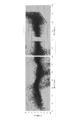
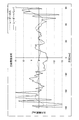
しかしながら、レーダ装置のアンテナをバンパ内に設置した場合、電磁波がバンパにより多重反射することによって、図8および図9に示すように、アンテナの放射特性が乱れ、物体が存在する方位の検出性能を劣化させてしまうという問題があった。
本開示は、こうした問題に鑑みてなされたものであり、アンテナの放射特性の乱れに基づく方位誤差を検出する技術、更には、方位の検出性能を向上させる技術を提供することを目的とする。
本開示の方位誤差検出方法は、車両のバンパ内に設置され、連続波を用いて物体が存在する方位を少なくとも検出する車載レーダ装置に適用され、第1のステップから第4のステップにより構成されている。
第1のステップでは、連続波を送受信することで得られた信号を周波数解析することによって、連続波を反射した物体との相対速度を求める。第2のステップでは、第1のステップでの周波数解析によって物体の存在が認められた周波数ビン毎に、物体が位置する方位の推定値である推定方位を求める。第3のステップでは、自車両に対する停止物の相対速度と該停止物が位置する方位との関係を表す理論曲線を算出する。第4のステップでは、停止物について求められた推定方位を用いて、理論曲線に対する推定方位の誤差である方位誤差を求める。
また、本開示の方位誤差検出装置は、上述した第1のステップの処理を実行する相対速度算出部と、上述した第2のステップの処理を実行する方位推定部と、上述した第3のステップの処理を実行する理論曲線算出部と、上述の第4のステップの処理を実行する誤差算出部とを備える。
つまり、本開示では、自車両と停止物との相対速度と方位の関係を表す理論曲線を求めると共に、連続波からなるレーダ波を反射した停止物との相対速度および反射波の到来方向を求め、この両者を比較することによって方位誤差を求めている。このような構成によれば、既存のCWレーダ
(Continuous Wave Radar)により得られる情報を処理することにより、バンパの影響によって生じる方位の検出誤差を求めることができる。しかも、新たな構造物を付加する必要がないため、既存の装置にも簡単に適用することができる。
(Continuous Wave Radar)により得られる情報を処理することにより、バンパの影響によって生じる方位の検出誤差を求めることができる。しかも、新たな構造物を付加する必要がないため、既存の装置にも簡単に適用することができる。
更に、本開示の車載レーダ装置は、上述の方位誤差検出装置と、補正値算出部と、方位補正部とを備える。補正値算出部は、誤差算出部にて求められた方位誤差に対して統計的な処理を施すことにより周波数ビン毎に誤差補正値を求める。方位補正部は、方位推定部にて推定された方位を、誤差補正値を用いて補正する。
このように構成された本開示によれば、アンテナの放射特性の乱れなどに基づく方位の検出誤差が抑制されるため、方位の検出精度を向上させることができる。
なお、特許請求の範囲に記載した括弧内の符号は、一つの態様として後述する実施形態に記載の具体的手段との対応関係を示すものであって、本開示の技術的範囲を限定するものではない。
なお、特許請求の範囲に記載した括弧内の符号は、一つの態様として後述する実施形態に記載の具体的手段との対応関係を示すものであって、本開示の技術的範囲を限定するものではない。
添付図面において:
車載レーダ装置の構成を示すブロック図である。
メイン処理のフローチャートである。
方位誤差学習処理のフローチャートである。
側方停止物体の相対速度および方位の検出され方を示す説明図である。
理論曲線が自車速に応じて変化する様子を示す説明図である。
検出される相対速度と方位の関係の理論値を示す理論曲線と方位誤差を示す説明図である。
方位誤差の測定結果を実際の方位に対応付けてプロットしたグラフである。
(a)がアンテナ本来の指向性、(b)がバンパによって乱された指向性を例示する模式図である。
アンテナ本来の放射特性およびバンパによって乱された放射特性を示すグラフである。
以下に本開示が適用された実施形態について、図面を用いて説明する。
[構成]
図1に示す車載レーダ装置1は、アンテナ部2と送受信部3と信号処理部4とを備え、電磁波を透過する材料で構成されたバンパ内に設置して使用される。ここでは、車両の進行方向に対して後側に設置されたバンパの進行方向に向かって右端付近に設置され、かつ、車両の側方を探査範囲に含むような向きに設置されている(図4参照)。また、車載レーダ装置1は、車載ローカルエリアネットワークである、図1に示す車載LAN5を介して、他の車載装置と通信可能に接続されている。
[構成]
図1に示す車載レーダ装置1は、アンテナ部2と送受信部3と信号処理部4とを備え、電磁波を透過する材料で構成されたバンパ内に設置して使用される。ここでは、車両の進行方向に対して後側に設置されたバンパの進行方向に向かって右端付近に設置され、かつ、車両の側方を探査範囲に含むような向きに設置されている(図4参照)。また、車載レーダ装置1は、車載ローカルエリアネットワークである、図1に示す車載LAN5を介して、他の車載装置と通信可能に接続されている。
アンテナ部2は、図1に示すように水平方向に一列に配置された複数のアンテナを備え、レーダ波として電磁波を送受信する。
送受信部3は、多周波CW(連続波)からなるレーダ波を、アンテナ部2を介して一定時間間隔で周期的に送受信すると共に、アンテナ部2を構成する各アンテナで受信される受信信号毎に、受信信号と送信信号との差の周波数成分からなるビート信号を生成し、これをA/D変換した受信データを信号処理部4に供給する周知のものである。なお、多周波CWは、1MHz程度ずつ周波数が異なるGHzオーダの複数の連続波からなる。
送受信部3は、多周波CW(連続波)からなるレーダ波を、アンテナ部2を介して一定時間間隔で周期的に送受信すると共に、アンテナ部2を構成する各アンテナで受信される受信信号毎に、受信信号と送信信号との差の周波数成分からなるビート信号を生成し、これをA/D変換した受信データを信号処理部4に供給する周知のものである。なお、多周波CWは、1MHz程度ずつ周波数が異なるGHzオーダの複数の連続波からなる。
信号処理部4は、CPU41、ROM42、RAM43を中心に構成された周知のマイクロコンピュータからなり、ROMに記憶されたプログラムに従って、レーダ波を反射した物体を検出し、その物体に関する情報を生成するメイン処理を少なくとも実行する。なお、RAM43の一部は、車載レーダ装置1の電源をオフしてもメモリの内容が保持される不揮発性メモリで構成されており、この不揮発性メモリには、物体との相対速度(ここでは周波数解析により得られる周波数ビン)と、その相対速度での方位誤差との対応関係を表す方位補正テーブルが記憶されている。
[処理]
次に、信号処理部4のCPU41が実行するメイン処理について、図2のフローチャートを用いて説明する。本処理は、レーダ波を送受信する測定サイクル毎に起動する。
次に、信号処理部4のCPU41が実行するメイン処理について、図2のフローチャートを用いて説明する。本処理は、レーダ波を送受信する測定サイクル毎に起動する。
信号処理部4を構成するCPU41は、本処理が起動すると、S110にて、送受信部3がレーダ波を送受信することで得られる一測定サイクル分のビート信号のサンプリングデータを取得する。なお、一測定サイクルには、多周波CWの全ての送信周波数に関するサンプリングデータが含まれている。
S120では、サンプリングデータを周波数解析することにより、多周波CWの送信周波数毎かつアンテナ部2を構成するアンテナ毎に周波数スペクトルを算出する。ここでは、周波数解析として高速フーリエ変換(FFT)を用いる。これにより得られる周波数スペクトルの周波数ビンは、レーダ波を反射した物体との相対速度を表す。
S130では、S120にて求められた周波数スペクトルに基づき、アンテナ毎に平均周波数スペクトルを算出する。
S140では、平均周波数スペクトルから、受信強度が予め設定された閾値以上となるピーク値が検出される周波数ビンを抽出し、その周波数ビン毎に、方位推定処理を実行する。方位推定処理は、MUSIC(Multiple
Signal Classification)等の高分解能な推定処理が望ましいが、ビームフォーミング等を用いてもよい。
Signal Classification)等の高分解能な推定処理が望ましいが、ビームフォーミング等を用いてもよい。
RAM43には方位補正テーブルが記憶されている。
S150では、S140で推定された方位(以下「推定方位」という)を、方位補正テーブルを用いて補正する。具体的には、方位推定の対象となった周波数ビンをインデックスとして方位補正テーブルから方位誤差を取得し、その取得した方位誤差を推定方位に加算することで補正する。
S150では、S140で推定された方位(以下「推定方位」という)を、方位補正テーブルを用いて補正する。具体的には、方位推定の対象となった周波数ビンをインデックスとして方位補正テーブルから方位誤差を取得し、その取得した方位誤差を推定方位に加算することで補正する。
S160では、平均周波数スペクトルにピークを発生させた各物体について、その物体との相対速度、その物体が存在する方位を少なくとも含んだ物体情報を生成し、車載LAN5を介して、物体情報を利用する各車載装置に提供する。
S170では、先のS130およびS140での処理結果を用いて、方位誤差を学習し、方位補正テーブルを更新する方位誤差学習処理を実行して本処理を終了する。
次に、方位誤差学習処理の詳細を、図3のフローチャートを用いて説明する。
次に、方位誤差学習処理の詳細を、図3のフローチャートを用いて説明する。
信号処理部4を構成するCPU41は、本処理が起動すると、S210にて、車載LAN5を介して自車速を取得し、その自車速が予め設定された速度閾値より大きいか否かを判断する。速度閾値は、S140で算出される推定方位と、レーダ波を反射した物体との相対速度との関係を表すグラフ(図6参照)が十分に大きな傾きを有するような値に設定される。
自車速が速度閾値以下より大きければ(S210:YES)、S220に進み、自車速が速度閾値以下であれば(S210:NO)、学習の効果を期待できないものと判断して本処理を終了する。
S220では、S130,S140での処理結果に基づき、自車両とレーダ波を反射した物体との相対速度および推定方位からなる二次元データの分布Pを作成する。
S230では、自車速Vselfに応じて、停止物について検出される相対速度yと方位xとの関係を表す理論曲線Cを(1)式を用いて算出する。但し、θinstを車載レーダ装置1の取付角度、Aを定数、N_FFT_BINをFFTポイント数(例えば256)とする。

S250では、S240で求めた近似度が、予め設定された近似閾値以上であるか否かを判断する。近似度が近似閾値より大きければ(S250:YES)S260に進み、近似度が近似閾値以下であれば(S250:NO)、レーダ波を反射した物体は停止物ではないものとして、本処理を終了する。
S260では、分布Pを構成するデータを周波数ビン毎に方位誤差を算出する。
S270では、S260で求めた方位誤差を用いて、方位補正テーブルを更新して、本処理を終了する。具体的には、例えば、今回求められた方位誤差と方位補正テーブルの記憶内容とを重み付け加算した結果によって更新することが考えられる。
[原理]
なお、方位補正テーブルの生成には、レーダ波を反射した物体が停止物である場合、側方停止物の相対速度と、停止物が存在する方位との間に対応関係があることを利用している。
なお、方位補正テーブルの生成には、レーダ波を反射した物体が停止物である場合、側方停止物の相対速度と、停止物が存在する方位との間に対応関係があることを利用している。
即ち、車両の側方に壁面などの停止物が存在する場合、壁面のさまざまな箇所から反射波が得られる。そして、壁面の反射点が存在する方位と、その反射点について検出される相対速度とは、図5に示す関係を有する。即ち、反射点が車載レーダ装置1が取り付けられた位置の真横(車両の進行方向に対して90°の位置)である場合、その反射点の相対速度は0となる。この真横の反射点より車両の進行方向側に位置する反射点の相対速度は、自車両に接近してくることを表すプラスの値となる。また、真横の反射点より車両の進行方向とは反対側に位置する反射点の相対速度は、自車両から離れていくことを表すマイナスの値となる。いずれの場合も、その絶対値は、真横の位置から離れるほど大きな値となる。また、グラフは、自車両の真後ろ方向に対して線対称な形状となる。
更に、車載レーダ装置1が0~180[deg]を探査範囲とし、しかも、探査範囲の0[deg]の方向が、車両の後方向に対し、車両の上方から見て右回りにθinst[deg]傾くように車両に取り付けられている場合、車両の真横方向は、90+θinst[deg]となる。図では、θinst=50[deg]の場合を示す。
図4の取付状態を前提として、(1)式を用いて求めた理論曲線Cを図5に示す。図示されているように、理論曲線Cは自車速Vselfが遅いほど変化が小さく、自車速Vselfが早いほど、方向に対する相対速度(周波数ビン)の変化が大きくなる。なお、相対速度を表す周波数ビンは、0~N_FFT_BIN[bin]で表され、その中心のN_FFT_BIN/2[bin]を、相対速度がゼロの場合としている。この場合、N_FFT_BIN/2~N_FFT_BIN[bin]は、停止物が自車両に接近してくるように観測される物標接近領域、0~N_FFT_BIN/2[bin]は、停止物が自車両から離れていくように観測される物標離脱領域となる。
図6は、点線が理論曲線Cであり、実線が実データの分布Pを、周知の統計的な手法を用いて曲線で表したものである。即ち、この理論曲線Cと分布Pに基づく曲線との方位軸方向(図中の左右方向)における差がバンパ等の影響による方位誤差となる。
図7は、真の方向に対する方位誤差の測定値を、探査範囲内の各方向についてプロットしたものであり、ほぼ方位誤差0を中心に分布していることがわかる。なお、140[deg]付近の測定値は、測定精度が低いため、これを取り除いて示している。即ち、CWレーダでは、理論上、相対速度がゼロの物体を測定することができず、また相対速度がゼロの近辺の測定精度も低いためである。
[効果]
以上、説明したように、車載レーダ装置1では、停止物の相対速度と方位の関係を示す理論曲線Cを自車速Vselfから求めると共に、連続波からなるレーダ波を反射した物体との相対速度および物体が存在する方向(反射波の到来方向)を表す分布Pを求め、この両者を比較することによってバンパの影響によって生じる方位誤差を算出し、その結果に基づいて、検出された方位の補正に使用する方位補正テーブルを生成するようにされている。
以上、説明したように、車載レーダ装置1では、停止物の相対速度と方位の関係を示す理論曲線Cを自車速Vselfから求めると共に、連続波からなるレーダ波を反射した物体との相対速度および物体が存在する方向(反射波の到来方向)を表す分布Pを求め、この両者を比較することによってバンパの影響によって生じる方位誤差を算出し、その結果に基づいて、検出された方位の補正に使用する方位補正テーブルを生成するようにされている。
このように車載レーダ装置1によれば、バンパの影響によって生じる方位の検出誤差を抑制することができる。さらに、方位の検出精度を向上させることができる。しかも、このような効果を、新たな構造物を付加することなく、既存のCWレーダから得られる情報を処理することによって実現しているため、既存の装置にも簡単に適用することができる。
[他の実施形態]
以上、本開示の実施形態について説明したが、本開示は、上記実施形態に限定されることなく、種々の形態を採り得る。
以上、本開示の実施形態について説明したが、本開示は、上記実施形態に限定されることなく、種々の形態を採り得る。
(1)上記実施形態では、車載レーダ装置1は、学習により方位補正テーブルを随時更新するように構成されているが、予め作成された方位補正テーブルを更新することなくそのまま使用するように構成されていてもよい。
(2)上記実施形態では、分布Pが停止物に基づくものであるか否かを、分布Pと理論曲線Cとの近似度から判断しているが、車載カメラの画像から得られる情報や地図データ等を用いて判断するようにしてもよい。
(3)上記実施形態における一つの構成要素が有する機能を複数の構成要素に分散させたり、複数の構成要素が有する機能を一つの構成要素に統合させたりしてもよい。また、上記実施形態の構成の少なくとも一部を、同様の機能を有する公知の構成に置き換えてもよい。また、上記実施形態の構成の一部を省略してもよい。また、上記実施形態の構成の少なくとも一部を、他の上記実施形態の構成に対して付加または置換等してもよい。なお、特許請求の範囲に記載した文言のみによって特定される技術思想に含まれるあらゆる態様が本開示の実施形態である。
(4)本開示は、方位誤差検出方法および方位誤差検出装置の他、当該方位誤差検出装置を構成要素とする車載レーダ装置等のシステム、方位誤差検出装置としてコンピュータを機能させるためのプログラム、このプログラムを記録した媒体など、種々の形態で実現することもできる。
1…車載レーダ装置 2…アンテナ部 3…送受信部 4…信号処理部
Claims (6)
- 車両のバンパ内に設置され、連続波を用いて物体が存在する方位を少なくとも検出する車載レーダ装置において、前記バンパの影響によって生じる方位誤差を検出する方位誤差検出方法であって、
前記連続波を送受信することで得られた信号を周波数解析することによって、前記連続波を反射した物体との相対速度を求める第1のステップ(S120)と、
前記第1のステップでの周波数解析によって前記物体の存在が認められた周波数ビン毎に、前記物体が位置する方位の推定値である推定方位を求める第2のステップ(S130~S140)と、
自車両に対する停止物の相対速度と該停止物が位置する方位との関係を表す理論曲線を算出する第3のステップ(S230)と、
前記停止物について求められた前記推定方位を用いて、前記理論曲線に対する前記推定方位の誤差である方位誤差を求める第4のステップ(S240~S260)と、
を備えることを特徴とする方位誤差検出方法。 - 車両のバンパ内に設置され、連続波を用いて物体が存在する方位を少なくとも検出する車載レーダ装置において、前記バンパの影響による方位誤差を検出する方位誤差検出装置であって、
前記連続波を送受信することで得られた信号を周波数解析することによって、前記連続波を反射した物体との相対速度を求める相対速度算出部(4:S120)と、
前記相対速度算出部での周波数解析によって物体の存在が認められた周波数ビン毎に、反射波の到来方向の推定値である推定方位を求める方位推定部(4:S130~S140)と、
自車両に対する停止物の相対速度と該停止物が位置する方位との関係を表す理論曲線を算出する理論曲線算出部(4:S230)と、
前記停止物について求められた前記方位推定部での推定方位を用いて、前記理論曲線に対する前記推定方位の誤差を求める誤差算出部(4:S240~S260)と、
を備えることを特徴とする方位誤差検出装置。 - 前記連続波として多周波連続波を使用し、
前記方位推定部は、前記連続波の周波数毎に実施された周波数解析結果の平均値を用いて処理を行うことを特徴とする請求項2に記載の方位誤差検出装置。 - 前記誤差算出部は、前記方位推定部で求められた推定方位の分布と、前記理論曲線算出部で求められた理論曲線との類似度を求め、該類似度が予め設定された近似閾値より大きい場合に、前記分布に属する推定方位を、前記停止物について求められたものであると判断することを特徴とする請求項2または請求項3に記載の方位誤差検出装置。
- 請求項2または請求項3に記載の方位誤差検出装置と、
前記誤差算出部にて求められた方位誤差に対して統計的な処理を施すことにより前記周波数ビン毎に誤差補正値を求める補正値算出部(4:S270)と、
前記方位推定部にて推定された方位を、前記誤差補正値を用いて補正する方位補正部(4:S150)と、
を備えることを特徴とする車載レーダ装置。 - 請求項4に記載の方位誤差検出装置と、
前記誤差算出部にて求められた方位誤差に対して統計的な処理を施すことにより前記周波数ビン毎に誤差補正値を求める補正値算出部(4:S270)と、
前記方位推定部にて推定された方位を、前記誤差補正値を用いて補正する方位補正部(4:S150)と、
を備えることを特徴とする車載レーダ装置。
Priority Applications (2)
| Application Number | Priority Date | Filing Date | Title |
|---|---|---|---|
| US15/539,109 US10495743B2 (en) | 2014-12-24 | 2015-12-22 | Direction error detection method and apparatus using estimated directions, and in-vehicle radar apparatus |
| CN201580070386.6A CN107110956B (zh) | 2014-12-24 | 2015-12-22 | 使用了推定方位的方位误差检测方法以及装置、车载雷达装置 |
Applications Claiming Priority (2)
| Application Number | Priority Date | Filing Date | Title |
|---|---|---|---|
| JP2014-260584 | 2014-12-24 | ||
| JP2014260584A JP6358076B2 (ja) | 2014-12-24 | 2014-12-24 | 方位誤差検出方法および装置、車載レーダ装置 |
Publications (1)
| Publication Number | Publication Date |
|---|---|
| WO2016104472A1 true WO2016104472A1 (ja) | 2016-06-30 |
Family
ID=56150490
Family Applications (1)
| Application Number | Title | Priority Date | Filing Date |
|---|---|---|---|
| PCT/JP2015/085768 Ceased WO2016104472A1 (ja) | 2014-12-24 | 2015-12-22 | 推定方位を用いた方位誤差検出方法および装置、車載レーダ装置 |
Country Status (4)
| Country | Link |
|---|---|
| US (1) | US10495743B2 (ja) |
| JP (1) | JP6358076B2 (ja) |
| CN (1) | CN107110956B (ja) |
| WO (1) | WO2016104472A1 (ja) |
Cited By (1)
| Publication number | Priority date | Publication date | Assignee | Title |
|---|---|---|---|---|
| WO2026034176A1 (ja) * | 2024-08-05 | 2026-02-12 | 株式会社Soken | 角度誤差推定装置および角度誤差推定方法 |
Families Citing this family (7)
| Publication number | Priority date | Publication date | Assignee | Title |
|---|---|---|---|---|
| JP6769898B2 (ja) * | 2017-03-17 | 2020-10-14 | 株式会社デンソー | 方位誤差検出方法および装置 |
| DE112017007937B4 (de) * | 2017-10-23 | 2022-03-03 | Mitsubishi Electric Corporation | Kommunikationseinrichtung, Steuerungsverfahren und Steuerungsprogramm |
| US11209524B2 (en) * | 2019-09-30 | 2021-12-28 | Veoneer Us, Inc. | Detection system and method for characterizing targets |
| CA3150882A1 (en) | 2019-10-10 | 2021-04-15 | Thales Canada Inc. | System and method to determine low-speed and stationary state of a rail vehicle |
| JP7212604B2 (ja) * | 2019-10-31 | 2023-01-25 | 株式会社デンソー | 物体検出装置 |
| CN111308458B (zh) * | 2020-02-21 | 2023-06-02 | 北京理工睿行电子科技有限公司 | 一种基于车载毫米波雷达的自车速度估计方法 |
| EP4465074B1 (en) * | 2023-05-16 | 2026-03-25 | Aptiv Technologies AG | Method for determining a direction-of-arrival for radar waves impacted by vehicle components |
Citations (3)
| Publication number | Priority date | Publication date | Assignee | Title |
|---|---|---|---|---|
| JP2005017283A (ja) * | 2003-05-30 | 2005-01-20 | Fujitsu Ten Ltd | レーダ角度補正方法 |
| JP2010101643A (ja) * | 2008-10-21 | 2010-05-06 | Toyota Motor Corp | レーダ装置 |
| JP2012185039A (ja) * | 2011-03-04 | 2012-09-27 | Fujitsu Ten Ltd | レーダ装置及び該レーダ装置の到来角算出方法 |
Family Cites Families (16)
| Publication number | Priority date | Publication date | Assignee | Title |
|---|---|---|---|---|
| JPH09218257A (ja) | 1996-02-15 | 1997-08-19 | Toyota Motor Corp | 車載レーダ装置 |
| US6944543B2 (en) * | 2001-09-21 | 2005-09-13 | Ford Global Technologies Llc | Integrated collision prediction and safety systems control for improved vehicle safety |
| CN2694291Y (zh) * | 2003-12-11 | 2005-04-20 | 黄凯 | 微波汽车防撞驾驶雷达装置 |
| JP4394621B2 (ja) * | 2005-09-13 | 2010-01-06 | 株式会社小糸製作所 | 灯具の照射方向制御装置 |
| CN101042435B (zh) * | 2006-03-23 | 2011-03-23 | 欧姆龙汽车电子株式会社 | 单脉冲式雷达装置 |
| JP4356758B2 (ja) * | 2007-03-20 | 2009-11-04 | 株式会社デンソー | Fmcwレーダ |
| JP4492628B2 (ja) * | 2007-03-20 | 2010-06-30 | 株式会社デンソー | 干渉判定方法,fmcwレーダ |
| JP2009025195A (ja) * | 2007-07-20 | 2009-02-05 | Denso Corp | 到来波数推定方法、レーダ装置 |
| JP4497190B2 (ja) * | 2007-10-19 | 2010-07-07 | 株式会社デンソー | レーダ装置、および保持部材 |
| JP5519132B2 (ja) * | 2008-07-28 | 2014-06-11 | 株式会社デンソー | レーダ装置 |
| JP5278484B2 (ja) * | 2011-04-21 | 2013-09-04 | 株式会社デンソー | レーダ装置 |
| JP6009788B2 (ja) * | 2012-03-21 | 2016-10-19 | 富士通テン株式会社 | レーダ装置、および、信号処理方法 |
| JP6092596B2 (ja) * | 2012-11-28 | 2017-03-08 | 富士通テン株式会社 | レーダ装置、および、信号処理方法 |
| JP6181924B2 (ja) * | 2012-12-06 | 2017-08-16 | 富士通テン株式会社 | レーダ装置、および、信号処理方法 |
| CN103175503B (zh) * | 2013-03-12 | 2015-02-18 | 中国科学院长春光学精密机械与物理研究所 | 测量太阳指向方向与辐射计光轴夹角的方法 |
| JP6371534B2 (ja) * | 2014-02-12 | 2018-08-08 | 株式会社デンソーテン | レーダ装置、車両制御システム、および、信号処理方法 |
-
2014
- 2014-12-24 JP JP2014260584A patent/JP6358076B2/ja active Active
-
2015
- 2015-12-22 WO PCT/JP2015/085768 patent/WO2016104472A1/ja not_active Ceased
- 2015-12-22 CN CN201580070386.6A patent/CN107110956B/zh active Active
- 2015-12-22 US US15/539,109 patent/US10495743B2/en active Active
Patent Citations (3)
| Publication number | Priority date | Publication date | Assignee | Title |
|---|---|---|---|---|
| JP2005017283A (ja) * | 2003-05-30 | 2005-01-20 | Fujitsu Ten Ltd | レーダ角度補正方法 |
| JP2010101643A (ja) * | 2008-10-21 | 2010-05-06 | Toyota Motor Corp | レーダ装置 |
| JP2012185039A (ja) * | 2011-03-04 | 2012-09-27 | Fujitsu Ten Ltd | レーダ装置及び該レーダ装置の到来角算出方法 |
Cited By (1)
| Publication number | Priority date | Publication date | Assignee | Title |
|---|---|---|---|---|
| WO2026034176A1 (ja) * | 2024-08-05 | 2026-02-12 | 株式会社Soken | 角度誤差推定装置および角度誤差推定方法 |
Also Published As
| Publication number | Publication date |
|---|---|
| CN107110956B (zh) | 2020-03-31 |
| US10495743B2 (en) | 2019-12-03 |
| JP6358076B2 (ja) | 2018-07-18 |
| US20180156909A1 (en) | 2018-06-07 |
| JP2016121899A (ja) | 2016-07-07 |
| CN107110956A (zh) | 2017-08-29 |
Similar Documents
| Publication | Publication Date | Title |
|---|---|---|
| JP6520203B2 (ja) | 搭載角度誤差検出方法および装置、車載レーダ装置 | |
| JP6358076B2 (ja) | 方位誤差検出方法および装置、車載レーダ装置 | |
| CN113050082B (zh) | 用于处理雷达信号的方法及设备 | |
| JP6192910B2 (ja) | レーダ装置および物標高算出方法 | |
| CN108885249B (zh) | 搭载角度学习装置 | |
| JP2016003874A (ja) | レーダ装置 | |
| KR101752651B1 (ko) | 레이더 시스템의 클러터 제거 및 다중 표적 추적방법 | |
| JPWO2019116548A1 (ja) | レーダ信号処理装置、レーダ装置およびレーダ信号処理方法 | |
| JPWO2007015288A1 (ja) | 軸ずれ量推定方法及び軸ずれ量推定装置 | |
| JP2015132553A (ja) | 物体検出装置 | |
| JP2019039686A (ja) | レーダ装置および物標検出方法 | |
| WO2023058559A1 (ja) | 情報処理装置、物体追跡装置、追跡方法、プログラム | |
| JP2009128016A (ja) | レーダ装置、レーダ制御装置およびレーダ装置の制御方法 | |
| JP7160561B2 (ja) | 方位演算装置及び方位演算方法 | |
| CN113678023B (zh) | 雷达装置 | |
| US20230176208A1 (en) | Road shape estimation device, road shape estimation method, and computer-readable medium | |
| JP7212604B2 (ja) | 物体検出装置 | |
| EP4382962B1 (en) | An ego velocity estimator for radar systems | |
| EP4492088A1 (en) | Ego velocity assisted direction of arrival estimator for radar systems | |
| US20260023382A1 (en) | Device and method for creating dynamic occupancy grid map | |
| JP2018194391A (ja) | 方位誤差検出方法および装置 | |
| KR20140142490A (ko) | 차량용 레이더에서 그레이팅 로브 피크를 제거하는 장치 및 방법 |
Legal Events
| Date | Code | Title | Description |
|---|---|---|---|
| 121 | Ep: the epo has been informed by wipo that ep was designated in this application |
Ref document number: 15873040 Country of ref document: EP Kind code of ref document: A1 |
|
| WWE | Wipo information: entry into national phase |
Ref document number: 15539109 Country of ref document: US |
|
| NENP | Non-entry into the national phase |
Ref country code: DE |
|
| 122 | Ep: pct application non-entry in european phase |
Ref document number: 15873040 Country of ref document: EP Kind code of ref document: A1 |