WO2016104362A1 - Power train supporting structure for vehicle - Google Patents
Power train supporting structure for vehicle Download PDFInfo
- Publication number
- WO2016104362A1 WO2016104362A1 PCT/JP2015/085489 JP2015085489W WO2016104362A1 WO 2016104362 A1 WO2016104362 A1 WO 2016104362A1 JP 2015085489 W JP2015085489 W JP 2015085489W WO 2016104362 A1 WO2016104362 A1 WO 2016104362A1
- Authority
- WO
- WIPO (PCT)
- Prior art keywords
- vehicle
- transfer
- bracket
- support structure
- transmission
- Prior art date
Links
Images


Classifications
-
- B—PERFORMING OPERATIONS; TRANSPORTING
- B60—VEHICLES IN GENERAL
- B60K—ARRANGEMENT OR MOUNTING OF PROPULSION UNITS OR OF TRANSMISSIONS IN VEHICLES; ARRANGEMENT OR MOUNTING OF PLURAL DIVERSE PRIME-MOVERS IN VEHICLES; AUXILIARY DRIVES FOR VEHICLES; INSTRUMENTATION OR DASHBOARDS FOR VEHICLES; ARRANGEMENTS IN CONNECTION WITH COOLING, AIR INTAKE, GAS EXHAUST OR FUEL SUPPLY OF PROPULSION UNITS IN VEHICLES
- B60K17/00—Arrangement or mounting of transmissions in vehicles
- B60K17/22—Arrangement or mounting of transmissions in vehicles characterised by arrangement, location, or type of main drive shafting, e.g. cardan shaft
- B60K17/24—Arrangements of mountings for shafting
-
- B—PERFORMING OPERATIONS; TRANSPORTING
- B60—VEHICLES IN GENERAL
- B60K—ARRANGEMENT OR MOUNTING OF PROPULSION UNITS OR OF TRANSMISSIONS IN VEHICLES; ARRANGEMENT OR MOUNTING OF PLURAL DIVERSE PRIME-MOVERS IN VEHICLES; AUXILIARY DRIVES FOR VEHICLES; INSTRUMENTATION OR DASHBOARDS FOR VEHICLES; ARRANGEMENTS IN CONNECTION WITH COOLING, AIR INTAKE, GAS EXHAUST OR FUEL SUPPLY OF PROPULSION UNITS IN VEHICLES
- B60K17/00—Arrangement or mounting of transmissions in vehicles
- B60K17/34—Arrangement or mounting of transmissions in vehicles for driving both front and rear wheels, e.g. four wheel drive vehicles
- B60K17/348—Arrangement or mounting of transmissions in vehicles for driving both front and rear wheels, e.g. four wheel drive vehicles having differential means for driving one set of wheels, e.g. the front, at one speed and the other set, e.g. the rear, at a different speed
-
- B—PERFORMING OPERATIONS; TRANSPORTING
- B60—VEHICLES IN GENERAL
- B60K—ARRANGEMENT OR MOUNTING OF PROPULSION UNITS OR OF TRANSMISSIONS IN VEHICLES; ARRANGEMENT OR MOUNTING OF PLURAL DIVERSE PRIME-MOVERS IN VEHICLES; AUXILIARY DRIVES FOR VEHICLES; INSTRUMENTATION OR DASHBOARDS FOR VEHICLES; ARRANGEMENTS IN CONNECTION WITH COOLING, AIR INTAKE, GAS EXHAUST OR FUEL SUPPLY OF PROPULSION UNITS IN VEHICLES
- B60K17/00—Arrangement or mounting of transmissions in vehicles
- B60K17/34—Arrangement or mounting of transmissions in vehicles for driving both front and rear wheels, e.g. four wheel drive vehicles
- B60K17/354—Arrangement or mounting of transmissions in vehicles for driving both front and rear wheels, e.g. four wheel drive vehicles having separate mechanical assemblies for transmitting drive to the front or to the rear wheels or set of wheels
-
- B—PERFORMING OPERATIONS; TRANSPORTING
- B60—VEHICLES IN GENERAL
- B60K—ARRANGEMENT OR MOUNTING OF PROPULSION UNITS OR OF TRANSMISSIONS IN VEHICLES; ARRANGEMENT OR MOUNTING OF PLURAL DIVERSE PRIME-MOVERS IN VEHICLES; AUXILIARY DRIVES FOR VEHICLES; INSTRUMENTATION OR DASHBOARDS FOR VEHICLES; ARRANGEMENTS IN CONNECTION WITH COOLING, AIR INTAKE, GAS EXHAUST OR FUEL SUPPLY OF PROPULSION UNITS IN VEHICLES
- B60K5/00—Arrangement or mounting of internal-combustion or jet-propulsion units
- B60K5/04—Arrangement or mounting of internal-combustion or jet-propulsion units with the engine main axis, e.g. crankshaft axis, transversely to the longitudinal centre line of the vehicle
-
- B—PERFORMING OPERATIONS; TRANSPORTING
- B60—VEHICLES IN GENERAL
- B60K—ARRANGEMENT OR MOUNTING OF PROPULSION UNITS OR OF TRANSMISSIONS IN VEHICLES; ARRANGEMENT OR MOUNTING OF PLURAL DIVERSE PRIME-MOVERS IN VEHICLES; AUXILIARY DRIVES FOR VEHICLES; INSTRUMENTATION OR DASHBOARDS FOR VEHICLES; ARRANGEMENTS IN CONNECTION WITH COOLING, AIR INTAKE, GAS EXHAUST OR FUEL SUPPLY OF PROPULSION UNITS IN VEHICLES
- B60K5/00—Arrangement or mounting of internal-combustion or jet-propulsion units
- B60K5/12—Arrangement of engine supports
- B60K5/1208—Resilient supports
- B60K5/1216—Resilient supports characterised by the location of the supports relative to the motor or to each other
-
- B—PERFORMING OPERATIONS; TRANSPORTING
- B60—VEHICLES IN GENERAL
- B60K—ARRANGEMENT OR MOUNTING OF PROPULSION UNITS OR OF TRANSMISSIONS IN VEHICLES; ARRANGEMENT OR MOUNTING OF PLURAL DIVERSE PRIME-MOVERS IN VEHICLES; AUXILIARY DRIVES FOR VEHICLES; INSTRUMENTATION OR DASHBOARDS FOR VEHICLES; ARRANGEMENTS IN CONNECTION WITH COOLING, AIR INTAKE, GAS EXHAUST OR FUEL SUPPLY OF PROPULSION UNITS IN VEHICLES
- B60K5/00—Arrangement or mounting of internal-combustion or jet-propulsion units
- B60K5/12—Arrangement of engine supports
- B60K5/1241—Link-type support
-
- B—PERFORMING OPERATIONS; TRANSPORTING
- B60—VEHICLES IN GENERAL
- B60K—ARRANGEMENT OR MOUNTING OF PROPULSION UNITS OR OF TRANSMISSIONS IN VEHICLES; ARRANGEMENT OR MOUNTING OF PLURAL DIVERSE PRIME-MOVERS IN VEHICLES; AUXILIARY DRIVES FOR VEHICLES; INSTRUMENTATION OR DASHBOARDS FOR VEHICLES; ARRANGEMENTS IN CONNECTION WITH COOLING, AIR INTAKE, GAS EXHAUST OR FUEL SUPPLY OF PROPULSION UNITS IN VEHICLES
- B60K5/00—Arrangement or mounting of internal-combustion or jet-propulsion units
- B60K2005/006—Arrangement or mounting of internal-combustion or jet-propulsion units the internal combustion or jet propulsion unit is arranged behind the rear axle
Definitions
- the present invention relates to a powertrain support structure for a vehicle in which a powertrain provided with a transfer that transmits the output of a horizontally mounted engine to a rear wheel is supported by a mount bracket.
- a front wheel drive vehicle that drives only the front wheels and a four wheel drive vehicle that drives four wheels may be set.
- a power train composed of a horizontally mounted engine and a transmission includes, for example, a right mount bracket and a left mount bracket that are mounted at both ends in the vehicle width direction, and a rear mount bracket that is mounted on the transmission. It is supported by the vehicle body via
- the power train (which is synonymous with a power plant in this specification) includes a horizontal engine, a transmission, and a transfer.
- the power train is supported on the vehicle body via, for example, a right mount bracket and a left mount bracket that are attached to both ends in the vehicle width direction, and a rear mount bracket that is attached to the transfer.
- the rear mount bracket is connected to the transmission in the front-wheel drive vehicle, but may be connected to the transfer in the four-wheel drive vehicle.
- the front part of the rear mount bracket (engine rear mount bracket 66) is connected and fixed to the side part of the transfer in a four-wheel drive vehicle of a horizontally mounted engine.
- the rear portion of the bracket (member side mounting member 60) is fixedly connected to the engine rear mount member.
- the engine rear mount member is formed in a shape that swells above the vehicle between the driver's seat and the passenger seat and bridges the lower portion of the tunnel portion extending in the front-rear direction in the vehicle width direction. .
- a rear portion (member-side mounting member 60) of the rear mount bracket is disposed on the side of the propeller shaft that passes through the space surrounded by the tunnel portion and the engine rear mount member.
- Patent Document 1 since the mount bracket is positioned on the side of the propeller shaft, the length in the vehicle width direction in the tunnel portion is increased, and thus the space for the driver seat and the passenger seat may be reduced.
- Patent Document 1 has a problem in that an appropriate driving position cannot be set due to restrictions on the arrangement space of the accelerator pedal and the brake pedal.
- An object of the present invention is to provide a powertrain support structure for a vehicle that can suppress the influence on the interior of the vehicle even when the vehicle is equipped with a transfer in a vehicle equipped with a horizontally mounted engine.
- the output of the transmission is transmitted via a transverse engine whose rotational axis is positioned in the vehicle width direction of the vehicle, a transmission that transmits the output of the lateral engine to a front wheel via a drive shaft, and a propeller shaft.
- a powertrain support structure for a vehicle comprising a powertrain including a transfer for transmitting to a rear wheel, a rear portion of the powertrain, and a rear mount bracket for elastically supporting the powertrain so as to be swingable.
- the front portion of the rear mount bracket is connected to the transfer at a position below the drive shaft and in a vehicle vertical direction where the transmission and the transfer overlap in the vehicle width direction.
- the transmission and the transfer are superposed in the vehicle width direction” may be any state in which the transmission and the transfer overlap each other in the vehicle side view, and the transmission and the transfer are in contact with each other in the vehicle width direction. It does not have to be.
- the rear mount bracket may be a rear mount bracket integrally provided with an elastic member having elasticity, or a rear mount bracket constituted by a transfer side bracket, a vehicle body side bracket, and an elastic member having elasticity.
- the dead space below the drive shaft can be effectively used to suppress the influence on the vehicle interior.
- the powertrain support structure of the vehicle can place the position of the rear mount bracket relative to the vehicle body on the front side of the vehicle.
- the vehicle powertrain support structure allows the position of the rear mount bracket relative to the vehicle body. It can be easily arranged on the vehicle lower side.
- the vehicle powertrain support structure specifically, the rear mount bracket is a suspension.
- the vehicle can be disposed at a position in the vehicle vertical direction substantially equivalent to the cross member and at a position ahead of the vehicle relative to the suspension cross member.
- the powertrain support structure of the vehicle allows the powertrain support structure of the vehicle to lower the powertrain mounting position relative to the vehicle body to the vehicle lower side. For this reason, for example, in a vehicle type in which front-wheel drive and four-wheel drive are set, the powertrain support structure of the vehicle includes a connection position between the rear mount bracket and the transmission in the front wheel drive vehicle, and a rear mount bracket in the four wheel drive vehicle. And the transfer position can be easily arranged at substantially the same position.
- the total height of the front wheel drive vehicle and the total height of the four wheel drive vehicle can be made substantially the same.
- the vehicle power train support structure suppresses the bulging of the floor panel and the dash panel to the vehicle interior side, and the floor through which the propeller shaft is inserted. The enlargement of the tunnel can be suppressed.
- the powertrain support structure of the vehicle can lower the position where the powertrain is mounted on the vehicle body to the lower side of the vehicle, and can suppress the influence on the vehicle interior even when a transfer is provided.
- a vehicle powertrain support structure capable of suppressing the influence on the vehicle interior even when a vehicle equipped with a horizontally mounted engine is equipped with a transfer.
- the top view which shows the external appearance in the powertrain of a vehicle.
- the principal part right view which shows the principal part of the powertrain support structure in a right side view.
- the principal part bottom view which shows the principal part of the powertrain support structure in bottom view.
- the disassembled perspective view which shows the decomposition
- the principal part right view which shows the principal part of the powertrain support structure in another embodiment.
- the principal part bottom view which shows the principal part of the powertrain support structure in another embodiment.
- the right view which shows the transfer in another embodiment.
- the principal part right view which shows the principal part of the powertrain support structure in a right side view.
- the principal part perspective view which shows the principal part of the powertrain support structure in an assembly
- the disassembled perspective view which shows the state which removed the intermediate bracket. Explanatory drawing explaining the cross section along the vehicle width direction in a front side fastening part and a rear side fastening part.
- FIG. 1 is an explanatory diagram for explaining the configuration of the vehicle 1
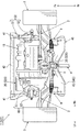
- FIG. 2 is a plan view of the appearance of the power train 7 of the vehicle 1
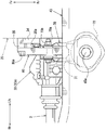
- FIG. 3 is a right side view of a main part of the power train support structure in a right side view.
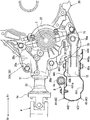
- FIG. 4 is a bottom view of the main part of the powertrain support structure in a bottom view
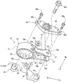
- FIG. 5 is an exploded perspective view of the main part of the powertrain support structure as viewed from below the vehicle.
- arrows Fr and Rr indicate the vehicle front-rear direction
- arrow Fr indicates the vehicle front
- arrow Rr indicates the vehicle rear
- arrows Rh and Lh indicate the vehicle width direction
- arrow Rh indicates the vehicle right direction
- arrow Lh indicates the vehicle left direction.
- the upper side in FIG. 3 is the upper side of the vehicle
- the lower side in FIG. 3 is the lower side of the vehicle.
- the vehicle 1 is a so-called FF-based four-wheel drive vehicle in which a power train 7 is arranged at the front thereof.
- the power train 7 (synonymous with a power plant) outputs the output of a horizontally mounted engine 10 arranged so that a crankshaft is positioned along the vehicle width direction via a drive shaft 2. 3 and the output of the horizontally placed engine 10 is transmitted to the rear wheel 6 via the propeller shaft 4 and the rear differential 5.
- the front portion of the vehicle 1 includes a pair of left and right front side frames (not shown) extending from the dash panel (not shown) to the front of the vehicle, and a sub disposed below the front side frame.
- the horizontal engine 10 is disposed between the frame 40 and the pair of left and right front side frames and the sub frame 40 and in front of the vehicle with respect to the steering gear box 8 fixed to the rear portion of the sub frame 40.
- the power train 7 is supported by these frames 40 via a support member described later.
- the steering gear box 8 connects a steering wheel (not shown) operated by an occupant and the front wheel 3, and performs an input rotation due to the operation of the steering wheel in a substantially cylindrical main body cylinder portion 8a extending in the vehicle width direction. It functions as a steering device that changes the direction of the front wheel 3 via a gear housed in (see FIG. 4).
- the sub-frame 40 connects a pair of left and right front and rear members 41 extending in the vehicle front-rear direction, a front cross member 42 that connects the front ends of the front and rear members 41 in the vehicle width direction, and a rear end of the front and rear members 41 in the vehicle width direction. And a suspension cross member 43 to which a suspension member such as the lower arm 9 is connected, and these members 41 to 43 are integrally formed in a substantially rectangular shape in plan view.
- the suspension cross member 43 is integrally formed by joining an upper panel 44 positioned on the upper side of the vehicle and a lower panel 45 positioned on the lower side of the vehicle, overlapping each other in the vertical direction of the vehicle. Yes.
- the upper panel 44 includes a top plate portion 441 that forms the upper surface of the suspension cross member 43, and an inner rear wall portion 442 that extends downward from the rear end of the top plate portion 441 to the vehicle rear side. And an inner front wall portion 443 extending downward from the front end of the top plate portion 441 and a front edge portion 444 extending from the front end of the inner front wall portion 443 toward the front of the vehicle.
- a bolt opening hole (not shown) and a groove portion 441a are formed in this order from the front of the vehicle at approximately the center in the vehicle width direction.
- the bolt opening hole is inserted with a connecting bolt 45a for connecting a rear mount bracket 70 described later.
- the recessed groove portion 441a is disposed with the steering gear box 8 and extends in the vehicle width direction.
- the concave groove portion 441a is formed in a substantially concave groove shape in which a part of the top plate portion 441 protrudes downward in the vehicle along the main body cylinder portion 8a of the steering gear box 8.
- the recessed groove portion 441a is formed in such a size that the main body cylinder portion 8a in the steering gear box 8 can be disposed.
- the inner front wall portion 443 is provided with a bracket insertion hole 443a in which a rear mount bracket 70, which will be described later, is formed so as to be inserted into the suspension cross member 43 from the front of the vehicle.
- the lower panel 45 is opposed to the top plate portion 441 of the upper panel 44 at the lower side of the vehicle, and has a bottom plate portion 451 that contacts the front edge portion 444 and a rear end of the bottom plate portion 451 toward the upper side of the vehicle. It is integrally formed with the extended outer rear wall 452.
- the bottom plate portion 451 is formed with a bolt opening hole (not shown) through which the connecting bolt 45a is inserted at a position facing the bolt opening hole of the upper panel 44 below the vehicle.
- the power train 7 (synonymous with a power plant) drives a horizontally mounted engine 10 disposed so that a crankshaft is positioned along the vehicle width direction and the output of the horizontally mounted engine 10
- a transmission 20 that outputs to the shaft 2 and a transfer 30 that outputs the output of the transmission 20 to the propeller shaft 4 are provided.
- the horizontal engine 10 is arranged on the right side in the vehicle width direction so that the output shaft (crankshaft) is located on the left side of the vehicle.
- the transmission 20 is disposed on the left side of the vehicle with respect to the horizontal engine 10, and is fastened and fixed to the horizontal engine 10 with the input shaft positioned substantially coaxially with the output shaft of the horizontal engine 10.
- the transmission 20 switches a plurality of gears to decelerate the input rotation, and outputs the output to an output shaft arranged in parallel to the lower rear side of the vehicle with respect to the input shaft.
- the pair of left and right drive shafts 2 connected to the output shaft of the transmission 20 are arranged substantially coaxially with the output shaft of the transmission 20.
- the drive shaft 2 connected to the front wheel 3 on the right side of the vehicle is connected to the output shaft of the transmission 20 via a transfer 30 described later.
- the transfer 30 is disposed so that the input shaft is positioned substantially coaxially with the output shaft on the right side of the vehicle in the transmission 20, and is fastened and fixed to the right side of the transmission 20 with a fastening bolt 30a.
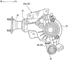
- the transfer 30 includes a transfer main body 30A and an intermediate bracket 80 attached to the lower portion of the transfer main body 30A.
- the transfer main body 30A includes a transfer case 31, a cover 32, a ring gear (not shown), a drive pinion (not shown), and a support leg 34.
- the transfer 30 (specifically, the transfer main body 30 ⁇ / b> A) includes a transfer case 31 positioned at the rear of the vehicle and a cover 32 positioned at the front of the vehicle with respect to the transfer case 31.
- the ring gear to which the input from the transmission 20 is transmitted and the drive pinion which is meshed with the ring gear and which is an output shaft are accommodated and held in an internal space constituted by
- the companion flange 33 is attached to the rear end of the drive pinion.
- the companion flange 33 is connected to the flange yoke 4 a of the propeller shaft 4.
- the transfer main body 30A has a pair of support legs extending from the transfer case 31 toward the front lower side of the vehicle and the lower side of the rear of the vehicle, as shown in FIGS. 34 is provided.
- the support legs 34 support an intermediate bracket 80 described later below the transfer case 31.
- Each support leg 34 includes a boss 35 to which the intermediate bracket 80 is attached.
- the boss portion 35 is in contact with the intermediate bracket 80 disposed substantially in the center of the vehicle 1 in the vehicle width direction, and is formed at the tip of the pair of support leg portions 34 toward the right side of the vehicle. Screw holes (not shown) into which the fastening bolts 80a for fastening the intermediate bracket 80 are screwed are formed in the boss portions 35, respectively.
- the power train 7 having the above-described configuration includes a right mount bracket 50 disposed along the vehicle width direction from the right side of the vehicle between the front side frame and the sub frame 40, and
- the left mount bracket 60, the right mount bracket 50, and the rear mount bracket 70 disposed behind the left mount bracket 60 are supported by the vehicle body, that is, the respective frames so as to be swingable.
- the right-side mounting bracket 50 connects the upper part on the right side in the vehicle width direction of the horizontally mounted engine 10 and the front side frame on the right side of the vehicle in a swingable manner.
- the right mount bracket 50 includes an engine side bracket 51 fixed to the horizontally mounted engine 10 and a vehicle body side bracket 52 fixed to the front side frame via an elastic rubber mount bush (not shown). Concatenated.
- the left mount bracket 60 slidably connects the upper left portion of the transmission 20 in the vehicle width direction and the front side frame on the left side of the vehicle.
- the left mount bracket 60 connects a transmission side bracket 61 fixed to the transmission 20 and a vehicle body side bracket 62 fixed to the front side frame via an elastic rubber mount bush (not shown). Configured.
- the rear mount bracket 70 is an intermediate bracket 80 fastened to the lower portion of the transfer body 30 ⁇ / b> A, specifically to the right side surface of the support leg 34, at the approximate center in the vehicle width direction of the vehicle 1.
- the transfer 30 and the suspension cross member 43 are connected so as to be swingable.
- the rear mount bracket 70 extends linearly in the vehicle front-rear direction, and includes a bracket front portion 71 connected to the intermediate bracket 80 and a bracket rear portion 72 connected to the suspension cross member 43. .
- the rear mount bracket 70 includes a bracket front portion 71 connected to the intermediate bracket 80 by connection bolts 70 a and nuts 70 b inserted along the vehicle width direction.
- the bracket rear portion 72 connected to the suspension cross member 43 is integrally formed in this order from the front of the vehicle by connecting bolts 45a and nuts 45b inserted along the vehicle vertical direction.
- the rear mount bracket 70 includes a bracket front portion 71 and a bracket rear portion 72 so as to be connected to the intermediate bracket 80 in front of the inner front wall portion 443 of the suspension cross member 43.
- the bracket front portion 71 faces the vehicle width direction at a predetermined interval, and also includes a pair of left and right counter plates 73 that sandwich an intermediate bracket 80 (a front mount bush 81 described later), and an upper portion of the pair of counter plates 73. And a pair of upper and lower reinforcing plates 74 that connect the lower portion and the lower portion in the vehicle width direction.
- the counter plate 73 is formed by bending a substantially rectangular metal flat plate that is long in the vehicle front-rear direction, and the counter plate main body portion 73a in which the vehicle width direction is the thickness direction, and the counter plate main body portion 73a. And a counter plate wall portion 73b extending from the vehicle vertical direction end portion toward the vehicle width direction outer side.
- the counter plate main body 73a of the counter plate 73 has a bolt insertion hole 73c through which a connection bolt 70a is inserted at the front end thereof.
- the reinforcing plate 74 is formed in a size that connects the rear end of the opposing plate wall 73b of the opposing plate 73 in the vehicle width direction.
- the bracket rear portion 72 is sandwiched between the upper panel 44 and the lower panel 45 in a state where it is connected to the suspension cross member 43 as shown in FIGS. 3 and 5.
- the bracket rear portion 72 includes a substantially cylindrical rear mount bush 75 whose axial direction is the vehicle vertical direction, and a metal bush support cylinder portion 76 into which the rear mount bush 75 is press-fitted.
- a small diameter tubular member having an inner diameter into which the connecting bolt 45a can be inserted a large diameter tubular member having a larger diameter than the small diameter tubular member, and a peripheral surface thereof face each other.
- a synthetic rubber having elasticity filled between a small-diameter tubular member and a large-diameter tubular member arranged on the same axis is included.
- the internal space in the rear mount bush 75 through which the connecting bolt 45a is inserted is referred to as a bolt insertion hole 75a.
- the bush support cylinder portion 76 is formed in a substantially cylindrical shape having an inner diameter allowing the rear mount bush 75 to be press-fitted and an axial length.
- the rear end of the bracket front portion 71 is joined to the outer peripheral surface of the bush support cylinder portion 76 by welding or the like.
- the intermediate bracket 80 includes a substantially cylindrical front mount bush 81 having an axial direction in the vehicle width direction, and an aluminum alloy bracket body 82 having a predetermined thickness.
- the peripheral surface faces a small-diameter tubular member having an inner diameter into which the connecting bolt 70a can be inserted, a large-diameter tubular member having a larger diameter than the small-diameter tubular member, and the front surface. And a synthetic rubber having elasticity filled between a small-diameter tubular member and a large-diameter tubular member arranged coaxially.
- the bracket body 82 is formed in a substantially inverted triangular shape when viewed from the side, and bolt insertion holes 82a through which fastening bolts 80a screwed into the boss portions 35 of the transfer 30 are inserted at both ends in the vehicle front-rear direction along the vehicle width direction. An opening is formed.
- the bracket body 82 is disposed so as to straddle the drive shaft 2 in the vehicle longitudinal direction.
- bracket body 82 is formed with a bush opening hole (not shown) into which the front mount bush 81 is press-fitted.
- This bush opening hole is formed in the vicinity of the position in the vehicle vertical direction where the lower end of the transmission 20 and the transfer 30 overlap in the vehicle width direction in the vicinity of the position in the vehicle longitudinal direction substantially the same as the position of the drive shaft 2 in the vehicle longitudinal direction. Has been.
- connection position between the transfer 30 and the rear mount bracket 70 is the position of the drive shaft 2 in the vehicle front-rear direction, and in the vicinity of the lower end of the transmission 20 below the drive shaft 2.
- the intermediate bracket 80 is configured so that the vehicle 30 and the transfer 30 overlap each other in the vehicle width direction.
- the rear mount is such that the transfer position of the transfer 30 and the rear mount bracket 70 with respect to the vehicle body is located in front of the inner front wall 443 of the suspension cross member 43 and below the drive shaft 2.
- a bracket 70 and an intermediate bracket 80 are configured.
- the intermediate bracket 80 is configured such that the vicinity of the lower end of the positioned power train 7 is a connection position of the rear mount bracket 70 to the transfer 30.
- TM side imaginary line that extends downward from the output shaft of the transmission 20 and a vehicle body side imaginary line that extends forward from the virtual midpoint in the axial direction of the rear mount bush 75 connected to the suspension cross member 43.
- the rear mount bracket 70 and the intermediate bracket 80 are configured so that the position of the intersection with the vehicle is the connection position of the transfer 30 and the rear mount bracket 70 with respect to the vehicle body.
- the powertrain support structure of the vehicle 1 that supports the powertrain 7 with the above-described configuration suppresses the influence on the vehicle interior even when the vehicle 1 equipped with the transverse engine 10 includes the transfer 30. can do.
- the rear mount bracket 70 is connected to the transfer 30 below the drive shaft 2, so that the powertrain support structure of the vehicle 1 places the position of the rear mount bracket 70 relative to the vehicle body on the vehicle front side. be able to.
- the powertrain support structure of the vehicle 1 has a rear mount bracket for the vehicle body.
- the position 70 can be easily arranged on the vehicle lower side.
- the bracket rear portion 72 of the rear mount bracket 70 is connected to the suspension cross member 43 disposed below the rear end of the transfer 30, so that the powertrain support structure of the vehicle 1 is substantially the same as the suspension cross member 43.
- the rear mount bracket 70 can be disposed at a position in the vehicle vertical direction at a position ahead of the vehicle relative to the suspension cross member 43.
- the powertrain support structure of the vehicle 1 can lower the mounting position of the powertrain 7 on the vehicle body to the vehicle lower side.
- the powertrain support structure of the vehicle 1 includes the connection position between the rear mount bracket and the transmission 20 in the front wheel drive vehicle, and the rear position in the four wheel drive vehicle.
- the connecting position of the mount bracket 70 and the transfer 30 can be easily made substantially the same position.
- the powertrain support structure of the vehicle 1 can make the total height of the front-wheel drive vehicle and the total height of the four-wheel drive vehicle substantially the same in a vehicle type in which front-wheel drive and four-wheel drive are set, for example.
- the power train support structure of the vehicle 1 can suppress the floor panel and the dash panel from bulging out to the vehicle interior side.
- the powertrain support structure of the vehicle 1 can be arranged on the vehicle lower side with respect to the conventional mounting position of the powertrain 7, so that the rear mount bracket 70 is arranged on the vehicle vertical direction lower side than the propeller shaft 4.
- the propeller shaft 4 itself can be disposed below the conventional one, thereby suppressing an increase in the size of the floor tunnel through which the propeller shaft 4 is inserted.
- the powertrain support structure of the vehicle 1 can lower the mounting position of the powertrain 7 with respect to the vehicle body to the lower side of the vehicle, and can suppress the influence on the vehicle interior even when the transfer 30 is provided. .
- bracket rear portion 72 has a bolt insertion hole 75a through which the connecting bolt 45a is inserted from the vehicle vertical direction, and is provided with a rear mount bush 75 having elasticity, so that the powertrain support structure of the vehicle 1 is attached to the vehicle body. Even if the mounting position of the powertrain 7 is lowered, interference with the vehicle body can be suppressed.
- the length of the rear mount bracket in the vertical direction of the vehicle tends to be long due to the outer diameter of the rear mount bush. For this reason, when the height of the member side bracket is increased and the mounting position of the power train 7 on the vehicle body is lowered, the transfer 30 and the propeller shaft 4 may interfere with the member side bracket.
- the powertrain support structure of the vehicle 1 has the length of the rear mount bracket 70 in the vehicle vertical direction. The length can be suppressed short.
- the rear mount bracket 70 that inserts the connecting bolt 45a into the rear mount bush 75 from the vehicle vertical direction can suppress the length in the vehicle vertical direction to be shorter than when the connecting bolt is inserted from the vehicle width direction. it can.
- the powertrain support structure of the vehicle 1 can suppress the thickness of the suspension cross member 43 to which the bracket rear portion 72 of the rear mount bracket 70 is coupled as compared with the case where the coupling bolt 45a is inserted from the vehicle width direction. it can.
- the powertrain support structure of the vehicle 1 is such that the transfer 30 and the propeller shaft 4 are not mounted on the vehicle body even when the mounting position of the powertrain 7 on the vehicle body is lowered by the rear mount bush 75 through which the connecting bolt 45a is inserted from the vehicle vertical direction. Interference with the side, for example, the floor panel can be prevented.
- the concave groove portion 441a is formed in the suspension cross member 43, and the steering gear box 8 is disposed in the concave groove portion 441a of the suspension cross member 43, so that the power train support structure of the vehicle 1 has a power to the vehicle body.
- the mounting position of the train 7 can be lowered further below the vehicle.
- the steering gear box 8 is often arranged behind the power train 7. For this reason, if the mounting position of the power train 7 on the vehicle body is lowered, for example, the rear end of the transfer 30 or the propeller shaft 4 may interfere with the steering gear box 8.
- the steering gear box 8 is disposed in the recessed groove portion 441a formed in the suspension cross member 43, so that the powertrain support structure of the vehicle 1 lowers the mounting position of the steering gear box 8 with respect to the vehicle body downward. be able to. That is, the powertrain support structure of the vehicle 1 can lower the mounting position of the powertrain 7 relative to the vehicle body further downward without interference between the powertrain 7 and the steering gear box 8.
- the powertrain support structure of the vehicle 1 has substantially the same mounting position of the steering gear box 8 with respect to the vehicle body between the front-wheel drive vehicle and the four-wheel drive vehicle. Can be in position.
- the powertrain 7 support structure of the vehicle 1 can further suppress the difference in the mounting position of the powertrain 7 with respect to the vehicle body between the front-wheel drive vehicle and the four-wheel drive vehicle, and can increase the ratio of common parts.
- the mounting position of the powertrain 7 on the vehicle body and the mounting position of the steering gear box 8 are substantially the same in the front-wheel drive vehicle and the four-wheel drive vehicle.
- the powertrain support structure of the vehicle 1 can share the geometry of the undercarriage between the front wheel drive vehicle and the four wheel drive vehicle, for example.
- the power train support structure of the vehicle 1 can lower the mounting position of the power train 7 relative to the vehicle body to the lower side of the vehicle by arranging the steering gear box 8 in the concave groove portion 441a of the suspension cross member 43.
- the design of the vehicle 1 in a vehicle type in which front wheel drive and four wheel drive are set can be facilitated.
- bracket front portion 71 and the transfer 30 are connected to each other via the intermediate bracket 80, and the front bracket bush 81 is provided in the intermediate bracket 80, so that the powertrain support structure of the vehicle 1 can be transferred.
- the front mount bush 81 can be easily interposed without separately forming the case 31 (transfer body 30A).
- the size of the front mount bush 81 may be different for each vehicle type, and therefore the front mount bush 81 is provided integrally with the transfer 30. It is necessary to make a transfer case 31 for each vehicle type.
- the intermediate bracket 80 is provided, and the intermediate bracket 80 is provided with the front mount bush 81, so that the powertrain support structure of the vehicle 1 is suitable for each vehicle type without making the transfer case 31 separately. Further, the transfer 30 and the rear mount bracket 70 can be connected via the front mount bush 81.
- the transfer 30 and the rear mount bracket 70 are connected via the intermediate bracket 80, and therefore the front mount bush 81 can be easily interposed without separately forming the transfer case 31. be able to.
- the vehicle includes a right mount bracket 50 that elastically supports the horizontally mounted engine 10 and a left mount bracket 60 that elastically supports the transmission 20 so that the transmission 20 can swing, and the rear mount bracket 70 is arranged in the vehicle width direction of the vehicle body.
- the right mount bracket 50 and the left mount bracket 60 are arranged substantially at the center, and are configured to suspend the power train 7 at a position in front of the vehicle and above the vehicle with respect to the bracket front portion 71.
- the power train support structure of the vehicle 1 can support the power train 7 that is a heavy object in a well-balanced manner and can suppress the influence on the vehicle interior.
- the center of gravity position of the power train 7 of the front wheel drive vehicle and the center of gravity position of the power train 7 of the four wheel drive vehicle are It will be different from the difference.
- the rear mount bracket 70 when the rear mount bracket 70 is arranged in accordance with the position of the center of gravity, the position of the rear mount bracket 70 in the vehicle width direction is different between the front wheel drive vehicle and the four wheel drive vehicle.
- the powertrain support structure of the vehicle 1 has the powertrain 7 of the front-wheel drive vehicle and the powertrain 7 of the four-wheel drive vehicle at substantially the same position. Can be supported.
- the powertrain support structure of the vehicle 1 supports the powertrain 7 in a well-balanced manner. can do.
- the power train support structure of the vehicle 1 balances the power train 7 that is a heavy object by the power train 7 being supported by the right mount bracket 50, the left mount bracket 60, and the rear mount bracket 70 so as to be swingable. While supporting well, the influence on a vehicle interior can be suppressed.
- the rear mount bracket 70 is configured by the bracket front portion 71 and the bracket rear portion 72 provided with the rear mount bush 75.
- the present invention is not limited to this.
- the bracket front portion, and A torque rod having a mount bush at the rear of the bracket may be used.
- the bracket rear portion 72 of the rear mount bracket 70 is configured to be directly connected to the suspension cross member 43.
- the present invention is not limited to this.
- the bracket rear portion 72 is connected to the suspension cross member 43 via a vehicle body side bracket. It may be configured to.
- front mount bush 81 and the rear mount bush 75 filled with synthetic rubber are used, the present invention is not limited to this, and a liquid seal mount bush or the like may be used.
- the front part of the rear mount bracket of the present invention corresponds to the bracket front part 71 of the embodiment
- the rear part of the rear mount bracket corresponds to the bracket rear part 72
- the cross member corresponds to the suspension cross member 43
- the groove portion corresponds to the groove portion 441a
- the engine side mounting bracket corresponds to the right side mounting bracket 50
- the mission side mounting bracket corresponds to the left side mounting bracket 60
- the present invention is not limited only to the configuration of the above-described embodiment, and many embodiments can be obtained.
- the intermediate bracket 80 may be omitted, and the bush press-fit portion 36 to which the rear mount bracket 70 is connected may be integrally formed with the transfer case 31.
- the power train support structure according to the first embodiment is shown in FIG. 6 showing a right side view of the main part, FIG. 7 showing a bottom view of the main part of the power train support structure, and a right side view of the transfer 30.
- a front mount bush 81 is press-fitted into a bush press-fit portion 36 that extends downward from the lower portion of the transfer case 31 toward the front of the vehicle.
- the transfer 30 includes a transfer main body 30A and a bush press-fit portion 36 that is integrally provided at the lower portion of the transfer main body 30A and into which the front mount bush 81 is press-fitted.
- the bush press-fit portion 36 may be connected to the rear mount bracket 70 via the front mount bush 81.
- the rear mount bracket 70 may be connected to the transfer 30, particularly the front mount bush 81 provided integrally with the transfer main body 30 ⁇ / b> A without using the intermediate bracket 80.
- the bush press-fit portion 36 is formed so that the connection position between the front mount bush 81 of the transfer 30 and the rear mount bracket 70 is equivalent to the above-described embodiment.
- the power train support structure of the vehicle 1 is the case where the transfer 30 is provided in the vehicle 1 in which the transverse engine 10 is mounted, as in the first embodiment described above.
- the influence on the passenger compartment can be suppressed.
- the powertrain support structure of the vehicle 1 suppresses an increase in the number of parts, and via the front mount bush 81.
- the rear mount bracket 70 and the transfer 30 can be connected.
- FIG. 1 the powertrain support structure of the vehicle 1 in this embodiment will be described in detail with reference to FIGS. 1, 2, and 9 to 12.
- FIG. 1 the powertrain support structure of the vehicle 1 in this embodiment will be described in detail with reference to FIGS. 1, 2, and 9 to 12.
- the powertrain support structure of the vehicle 1 in the second embodiment is devised so that the fastening bolts can be prevented from loosening and the rear mount bracket can be supported stably.
- the contact surface of the transfer and the rear mount bracket may slightly slide, which may cause loosening of the fastening bolt that fastens the transfer and the rear mount bracket.
- the second embodiment is also intended to provide a vehicle powertrain support structure that can stably support the rear mount bracket by suppressing the looseness of the fastening bolt.
- FIG. 1 and FIG. 2 show a right side view of the main part of the powertrain support structure in the right side view
- FIG. 10 shows a perspective view of the main part of the powertrain support structure in the assembled state
- FIG. 11 shows a state in which the intermediate bracket 580 is removed.
- FIG. 12 shows an exploded perspective view
- FIG. 12 shows an explanatory view for explaining a cross section along the vehicle width direction in the front side fastening portion 650 and the rear side fastening portion 660.
- FIG. 12A in FIG. 12 shows a cross-sectional view of the front side fastening portion 650
- FIG. 12B shows a cross-sectional view of the rear side fastening portion 660.
- the vehicle 501 is a so-called FF-based four-wheel drive vehicle in which the power train 7 is disposed in the front part thereof.
- this power train 507 (synonymous with a power plant) outputs the output of a horizontally mounted engine 10 arranged so that the crankshaft is positioned along the vehicle width direction via the drive shaft 2. 3 and the output of the horizontally placed engine 10 is transmitted to the rear wheel 6 via the propeller shaft 4 and the rear differential 5.
- the arrangement of the power train 7 and the specific configuration of the steering gear box 8 are the same as those in the first embodiment.
- the sub frame 40 has the same basic configuration as that of the first embodiment except for the specific configuration of the suspension cross member 43. That is, the subframe 40 includes a pair of left and right front and rear members 41, a front cross member 42, and a suspension cross member 543.
- the suspension cross member 543 in the second embodiment has an upper panel 544 positioned on the upper side of the vehicle and a lower panel 545 positioned on the lower side of the vehicle, as shown in FIG. They are integrally formed by overlapping and joining in the direction.
- the upper panel 544 has a cross section along the vehicle front-rear direction formed in a cross-sectional hat shape in which the vehicle lower portion is opened.
- a bolt opening hole (not shown) through which a connection bolt 545a for connecting a rear mount bracket 570 to be described later is inserted is formed in the vehicle vertical direction at substantially the center in the vehicle width direction of the vehicle 501.
- the front surface of the upper panel 544 is provided with a bracket insertion hole 546 in which a rear mount bracket 570, which will be described later, is formed so as to be open from the front of the vehicle.
- the lower panel 545 has a substantially flat cross section along the vehicle longitudinal direction.
- the lower panel 545 is formed with a bolt opening hole (not shown) through which the connection bolt 545a is inserted so as to face the bolt opening hole of the upper panel 544 in the vehicle vertical direction, and the connection bolt 545a is screwed.
- a weld nut 545b is welded.
- the power train 507 includes a right mount bracket 50 disposed along the vehicle width direction from the right side of the vehicle in a space surrounded by the pair of left and right front side frames and the sub frame 40. And a left mount bracket 60, a right mount bracket 50, and a rear mount bracket 570 disposed behind the left mount bracket 60 so as to be swingable on the vehicle body side.
- the rear mount bracket 570 connects the rear portion of the power train 507 (an intermediate bracket 580 described later) and the suspension cross member 543 so as to be capable of swinging at approximately the center in the vehicle width direction of the vehicle 501. Yes.
- the rear mount bracket 570 includes a bracket front portion 571 that is swingably connected to the rear portion of the power train 507 by a connecting bolt 570a, and a bracket that is swingably connected to the suspension cross member 543 by a connecting bolt 545a.
- the rear portion 572 is integrally formed by joining in this order from the front of the vehicle.
- the bracket front portion 571 is configured by arranging substantially flat metal plates having a thickness in the vehicle width direction so as to face each other at a predetermined interval in the vehicle width direction. Furthermore, a bolt insertion hole (not shown) through which the connecting bolt 570a is inserted is formed in the metal flat plate on the right side of the vehicle in the bracket front portion 571. On the other hand, a weld nut (not shown) to which the connecting bolt 570a is screwed is welded to the metal flat plate on the left side of the vehicle in the bracket front portion 571.
- the bracket rear portion 572 is configured by press-fitting an elastic mount bush into a metal tubular member whose axial direction is the vehicle vertical direction. As shown in FIG. 9, the bracket rear portion 572 is connected to the suspension cross member 543 by using connection bolts 545a so as to be sandwiched between the upper panel 544 and the lower panel 545.
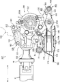
- the power train 507 supported on the vehicle body in this manner includes a horizontally placed engine 10 disposed so that the crankshaft is positioned along the vehicle width direction, A transmission 520 that outputs the output of the engine 10 to the drive shaft 2 and a transfer 530 that outputs the output of the transmission 520 to the propeller shaft 4 are provided.
- the horizontal engine 10 is arranged on the right side in the vehicle width direction so that the output shaft (crankshaft) is located on the left side of the vehicle, as shown in FIG. *
- the transmission 520 is arranged on the left side of the vehicle with respect to the horizontal engine 10 and is fastened and fixed to the horizontal engine 10 so that the input shaft is positioned substantially coaxially with the output shaft of the horizontal engine 10. .
- the transmission 520 switches a plurality of gears to decelerate the input rotation, and outputs it to an output shaft arranged in parallel to the vehicle rear lower side with respect to the input shaft.
- the transmission 520 is formed with a boss portion (not shown) to which a fastening bolt for fastening the transfer 530 is screwed toward the right side of the vehicle. Further, as shown in FIGS. 10 and 11, the transmission 520 communicates with a rear bracket insertion hole 585 a of an intermediate bracket 580 described later and a screw to which a rear fastening bolt 606 is screwed in a state where the transfer 530 is assembled.
- a boss portion 21 having a hole 21a is formed toward the right side of the vehicle.
- the pair of left and right drive shafts 2 connected to the output shaft of the transmission 520 are disposed substantially coaxially with respect to the output shaft of the transmission 520.
- the drive shaft 2 connected to the front wheel 3 on the right side of the vehicle is connected to the output shaft of the transmission 520 via the transfer 530.
- the transfer 530 is arranged so that the input shaft is positioned substantially coaxially with the output shaft on the right side of the vehicle in the transmission 520.
- the transfer 530 has a function of outputting the input transmitted from the transmission 520 to an output shaft that is substantially orthogonal to the input shaft.
- the transfer 530 includes a transfer main body 530A and an intermediate bracket 580 attached to the lower part of the transfer main body 530A.
- the transfer main body 530A includes a transfer case 531, a cover 532, a ring gear (not shown), a drive pinion (not shown), an upper mounting base 534, and a lower mounting base 535. *
- the transfer 530 (specifically, the transfer main body 530A) includes a transfer case 531 located at the rear of the vehicle and a cover 532 located at the front of the vehicle.
- the cover 532 is configured to be hollow inside.
- This transfer body 530A has a ring gear rotatably supported with the vehicle width direction as a rotation axis and a drive pinion gear meshing with the ring gear at the front end, and is rotatably supported with the vehicle longitudinal direction as the rotation axis. And a drive pinion which is an output shaft.
- a companion flange 33 to which the flange yoke 4a of the propeller shaft 4 is connected is attached to the rear end of the drive pinion.
- the transfer 530 having such a configuration is fastened and fixed to the right side surface of the transmission 520 using a plurality of fastening bolts, as shown in FIGS. 9 to 11. *
- the left side of the transfer case 531 includes a substantially flat upper attachment base 534 extending upward and a substantially flat lower attachment base 535 extending downward of the vehicle. ing.
- the upper mounting base 534 is formed in a shape that projects upward in the vehicle longitudinal direction from the vicinity of the rear end of the transfer case 531 to the front end in the vehicle side view. .
- a bolt hole (not shown) through which the first fastening bolt 601 screwed into the transmission 520 is inserted is formed in the vicinity of the front end.
- a fastening portion between the transmission 520 and the transfer 530 (specifically, the transfer main body 530A) fastened using the first fastening bolt 601 is defined as a first fastening portion 610.
- a bolt hole (not shown) through which the second fastening bolt 602 screwed into the transmission 520 is inserted is formed in the upper mounting base 534 in the vicinity of the rear end.
- a fastening portion between the transmission 520 and the transfer 530 (specifically, the transfer main body 530A) fastened using the second fastening bolt 602 is a second fastening portion 620.
- the lower mounting base 535 is formed in a shape such that its rear end is located in the vicinity of the rear end of the transfer case 531, and its front end protrudes below the front end of the transfer case 531 toward the front of the vehicle. ing.
- the lower mounting base 535 is formed with a bolt hole (not shown) through which the third fastening bolt 603 screwed into the transmission 520 is inserted in the vicinity of the front end.
- a fastening portion between the transmission 520 and the transfer 530 (specifically, the transfer main body 530A) fastened using the third fastening bolt 603 is referred to as a third fastening portion 630.
- a bolt hole (not shown) through which the fourth fastening bolt 604 threadedly engaged with the transmission 520 is inserted is formed in the lower mounting base 535 in the vicinity of the rear end.
- a fastening portion between the transmission 520 and the transfer 530 (specifically, the transfer main body 530A) fastened using the fourth fastening bolt 604 is referred to as a fourth fastening portion 640.
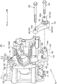
- the transfer 530 particularly the lower mounting base 535 of the transfer body 530 ⁇ / b> A, includes a front bracket mounting portion 536 and a rear bracket mounting portion 537 to which an intermediate bracket 580 described later is mounted. Is formed.
- the front bracket mounting portion 536 is integrally formed with the lower mounting base 535 so as to be erected toward the right side of the vehicle on the vehicle front side of the third fastening portion 630.
- the front bracket mounting portion 536 has a flat surface that comes into contact with the intermediate bracket 580 on the right side of the vehicle, and a screw hole 536a into which the front fastening bolt 605 is screwed has a vehicle width direction. It is formed along.
- the rear bracket mounting portion 537 is a vehicle between the third fastening portion 630 and the fourth fastening portion 640, at the upper portion of the lower mounting base portion 535, from the vicinity of the fourth fastening portion 640.
- the lower mounting base 535 is integrally formed so as to stand upright. That is, the rear bracket mounting portion 537 is formed in the transfer case 531 in the vicinity of the output shaft to which the propeller shaft 4 is connected.
- the rear bracket mounting portion 537 is formed such that the left side of the vehicle contacts the boss portion 21 of the transmission 520 and the right side of the vehicle contacts the intermediate bracket 580.
- the rear bracket mounting portion 537 is formed with a transfer insertion hole 537a that communicates with the screw hole 21a of the boss portion 21 in the transmission 520 in the vehicle width direction and through which the rear fastening bolt 606 is inserted.
- the intermediate bracket 580 includes a substantially cylindrical mounting bush 581 having an axial direction in the vehicle width direction and an aluminum alloy bracket body 582 having a predetermined thickness in the vehicle width direction. Prepare.
- the mount bush 581 is coaxial so that the small diameter tubular member having an inner diameter into which the connecting bolt 570a can be inserted, the large diameter tubular member having a larger diameter than the small diameter tubular member, and the peripheral surface face each other. And a synthetic rubber having elasticity filled between the small-diameter tubular member and the large-diameter tubular member arranged above.
- the bracket body 582 has a substantially cylindrical front end portion 583, a central portion 584, and a rear end portion 585 extending in the vehicle width direction in this order from the front of the vehicle, and the front end portion 583, the central portion 584, and the center.
- the part 584 and the rear end part 585 are connected and integrally formed in a substantially V shape in side view.
- the front end 583 has a front bracket insertion hole 583a through which the front fastening bolt 605 is inserted and communicated with the screw hole 536a of the front bracket mounting portion 536 in the transfer 530. It is formed into a shape.
- the front end portion 583 of the intermediate bracket 580 is fastened and fixed to the front bracket mounting portion 536 of the transfer 530 (specifically, the transfer main body 530A) in a state where the transfer 530 is fastened to the transmission 520.
- this fastening location be the front side fastening part 650 (refer FIG.9 and FIG.10).
- the central portion 584 has a larger diameter than the outer diameter of the front end portion 583 and is formed in a substantially cylindrical shape having an inner diameter that allows the mounting bush 581 to be press-fitted.
- the central portion 584 is disposed below the drive shaft 2 and in the vicinity of the position in the vehicle vertical direction where the vicinity of the lower end of the transmission 520 and the transfer 530 overlap in the vehicle width direction.
- the central portion 584 is a vehicle in which the vicinity of the lower end of the transmission 520 and the transfer 530 (transfer body 530A) overlap in the vehicle width direction in the vicinity of the position in the vehicle front-rear direction substantially the same as the position of the drive shaft 2 in the vehicle front-rear direction. It is provided in the vicinity of the vertical position.
- connection position between the transfer 530 and the rear mount bracket 570 is the position of the drive shaft 2 in the vehicle front-rear direction and near the lower end of the transmission 520 below the drive shaft 2.
- the intermediate bracket 580 is configured so that the vehicle 30 and the transfer 30 overlap with each other in the vehicle width direction.
- the rear mount bracket 570 and the intermediate bracket are connected so that the transfer position of the transfer 530 and the rear mount bracket 70 is located in front of the suspension cross member 543 and below the drive shaft 2. 580 is configured.
- the rear end portion 585 is inserted with a rear fastening bolt 606 at a position above the center portion 584 and behind the rear bracket mounting portion 537 in the transfer 530.
- the transfer insertion hole 537 a and the rear bracket insertion hole 585 a communicating with the screw hole 21 a of the boss portion 21 in the transmission 520 are formed.
- the rear end portion 585 of the intermediate bracket 580 is fastened and fixed to the boss portion 21 of the transmission 520 with the rear bracket mounting portion 537 of the transfer 530 sandwiched in a state where the transfer 530 is fastened to the transmission 520.
- the power train support structure of the vehicle 501 includes the transmission 520, the transfer 530, And the rear side fastening part 660 (refer FIG.9 and FIG.10) which fastens the intermediate bracket 580 together is comprised.
- the powertrain support structure of the vehicle 501 that realizes the above configuration is similar to the first embodiment even if the vehicle 501 equipped with the horizontally mounted engine 10 includes the transfer 530. The influence on the room can be suppressed.
- the powertrain support structure of the vehicle 501 in the second embodiment can stably support the rear mount bracket 570 by suppressing the looseness of the rear fastening bolt 606.
- the transfer 530 and the rear mount bracket 570 are connected via the intermediate bracket 580, so that the powertrain support structure of the vehicle 501 is suitable for each vehicle type without forming the transfer case 531 separately.
- 530 and the rear mount bracket 570 can be connected.
- the transmission 520, the transfer 530, and the intermediate bracket 580 are fastened together by the rear side fastening portion 660, the power train support structure of the vehicle 501 swings the power train 507 due to road surface unevenness or the like. At this time, the load acting on the intermediate bracket 580 can be transmitted to the transmission 520 via the rear fastening bolt 606.
- the powertrain support structure of the vehicle 501 can suppress, for example, slight sliding on the contact surface between the transfer 530 and the intermediate bracket 580, and can suppress loosening of the rear fastening bolt 606.
- the power train support structure of the vehicle 501 can reduce the load acting on the transfer 530, the transfer 530 can be prevented from being damaged.
- the power train support structure of the vehicle 501 includes the rear side fastening portion 660 that integrally fastens the transmission 520, the transfer 530, and the intermediate bracket 580, thereby suppressing the looseness of the rear fastening bolt 606, and
- the mount bracket 570 can be stably supported.
- the rear side fastening portion 660 is disposed between the third fastening portion 630 and the fourth fastening portion 640 that are adjacent to each other in a side view of the vehicle, so that the powertrain support structure of the vehicle 501 is configured with the rear fastening bolt 606. The loosening can be further suppressed, and a stable support state of the rear mount bracket 570 can be secured.
- the rear side fastening portion 660 is disposed between the adjacent third fastening portion 630 and the fourth fastening portion 640, so that the powertrain support structure of the vehicle 501 has rigidity in the vicinity of the boss portion 21 of the transmission 520. Can be improved.
- the powertrain support structure of the vehicle 501 can improve the support rigidity of the intermediate bracket 580 in the fastened state. For this reason, the powertrain support structure of the vehicle 501 can further suppress the loosening of the rear fastening bolt 606.
- the powertrain support structure of the vehicle 501 more reliably loosens the rear fastening bolt 606 by arranging the rear fastening portion 660 between the adjacent third fastening portion 630 and the fourth fastening portion 640. Since it can suppress, the stable support state of the rear mount bracket 570 can be ensured.
- the powertrain support structure of the vehicle 501 makes the rear fastening bolt 606 loose.
- gear noise transmitted to the vehicle body via the rear mount bracket 570 can be reduced.
- the transfer 530 outputs the output of the transmission 520 to the propeller shaft 4 connected to the drive pinion via the ring gear and the drive pinion gear.
- the powertrain support structure of the vehicle 501 can be transmitted to the vehicle body via the transfer case 531 and the rear mount bracket 570, the transfer case 531, and the rear fastening.
- Gear noise can be distributed and transmitted to a transmission path that is transmitted to the transmission 520 via the bolt 606.
- the powertrain support structure of the vehicle 501 can reduce gear noise transmitted from the vehicle body to the vehicle interior via the rear mount bracket 570, and can reduce discomfort given to the occupant.
- the powertrain support structure of the vehicle 501 is configured such that the rear side fastening portion 660 is disposed in the vicinity of the output shaft of the transfer 530, thereby suppressing the loosening of the rear fastening bolt 606 and the vehicle body via the rear mount bracket 570.
- the transmitted gear noise can be reduced.
- the intermediate bracket 580 having the mount bush 581 is used.
- the present invention is not limited to this, and the intermediate bracket 580 having no mount bush may be used.
- the bracket front portion 571 of the rear mount bracket 570 may be provided with a mount bush having elasticity.
- the rear mount bracket 570 is connected to the suspension cross member 543.
- the present invention is not limited to this, and the rear mount bracket 570 may be connected to a reinforcing member such as a frame member such as a frame or a cross member that reinforces the frame member. .
- the transfer 530 (transfer body 530A) and the intermediate bracket 580 are fastened at two locations using the front fastening bolt 605 and the rear fastening bolt 606, but the present invention is not limited to this, and the transfer 530 (transfer body 530A)
- the intermediate bracket 580 may be configured to be fastened at three or more locations.
- the present invention is not limited to this. It is good also as a structure co-tightened in more than the location.
- the front fastening bolt 605 is screwed into the boss portion of the transmission 520, and the transmission side 520, the transfer 530 (transfer body 530A), and the middle between the front side fastening portion 650 and the rear side fastening portion 660.
- the bracket 580 may be configured to be fastened together.
- the third fastening part 630 is arranged between the front fastening part 650 and the rear fastening part 660.
- the powertrain support structure of the vehicle 501 can more reliably suppress loosening of the front fastening bolt 605 and the rear fastening bolt 606, and can secure a more stable fastening state between the transmission 520 and the transfer 530. .
- the powertrain support structure of the vehicle 501 applies loads acting on the intermediate bracket 580 to the front fastening bolt 605 and the rear fastening bolt 606. Can be distributed and transmitted to the transmission 520.
- the powertrain support structure of the vehicle 501 can more reliably suppress loosening of the front fastening bolt 605 and the rear fastening bolt 606 and more reliably prevent the transfer 530 from being damaged.
- the load acting on the intermediate bracket 580 is distributed and transmitted to the transmission 520 via the front fastening bolt 605 and the rear fastening bolt 606, whereby the powertrain support structure of the vehicle 501 has the transfer 530 and the third The load transmitted to the transmission 520 through the fastening portion 630 can be reduced. For this reason, the powertrain support structure of the vehicle 501 can suppress loosening of the third fastening bolt 603 in the third fastening portion 630 and the like.
- the power train support structure of the vehicle 501 includes the front fastening portion 650 and the rear fastening portion 660 to which the transmission 520, the transfer 530 (transfer body 530A), and the intermediate bracket 580 are fastened together, and the front fastening portion 650. Since the third fastening portion 630 is disposed between the rear fastening bolt 660 and the rear fastening bolt 660, loosening of the front fastening bolt 605 and the rear fastening bolt 606 is more reliably suppressed, and more stable transmission 520 and transfer 530 are achieved. It is possible to secure the fastening state.
- the vehicle body of the present invention corresponds to the suspension cross member 543 of the embodiment
- the front part of the rear mount bracket corresponds to the bracket front part 571
- the fastening bolt corresponds to the rear fastening bolt 606
- the bracket insertion hole corresponds to the rear bracket insertion hole 585a
- the joint fastening portion corresponds to the rear fastening portion 660
- the fastening portions correspond to the first fastening portion 610, the second fastening portion 620, the third fastening portion 630, and the fourth fastening portion 640
- the adjacent fastening portions correspond to the third fastening portion 630 and the fourth fastening portion 640
- Adjacent joint fastening parts correspond to the front fastening part 650 and the rear fastening part 660
- the present invention is not limited only to the configuration of the above-described embodiment, and many embodiments can be obtained.
- the output of the transmission is transmitted via a transverse engine whose rotational axis is positioned in the vehicle width direction of the vehicle, a transmission that transmits the output of the lateral engine to a front wheel via a drive shaft, and a propeller shaft.
- a powertrain support structure for a vehicle comprising a powertrain including a transfer for transmitting to a rear wheel, a rear portion of the powertrain, and a rear mount bracket for elastically supporting the powertrain so as to be swingable.
- the front portion of the rear mount bracket is connected to the transfer at a position below the drive shaft and in a vehicle vertical direction where the transmission and the transfer overlap in the vehicle width direction.
- the dead space below the drive shaft can be effectively used to suppress the influence on the vehicle interior.
- the powertrain support structure of the vehicle can place the position of the rear mount bracket relative to the vehicle body on the front side of the vehicle.
- the front portion of the rear mount bracket is connected to the transfer, so that the vehicle powertrain support structure The position can be easily arranged on the vehicle lower side.
- the powertrain support structure of the vehicle allows the powertrain support structure of the vehicle to lower the powertrain mounting position relative to the vehicle body to the vehicle lower side. For this reason, for example, in a vehicle type in which front-wheel drive and four-wheel drive are set, the powertrain support structure of the vehicle includes a connection position between the rear mount bracket and the transmission in the front wheel drive vehicle, and a rear mount bracket in the four wheel drive vehicle. And the transfer position can be easily arranged at substantially the same position.
- the total height of the front wheel drive vehicle and the total height of the four wheel drive vehicle can be made substantially the same.
- the vehicle power train support structure suppresses the bulging of the floor panel and the dash panel to the vehicle interior side, and the floor through which the propeller shaft is inserted. The enlargement of the tunnel can be suppressed.
- the powertrain support structure of the vehicle can lower the position where the powertrain is mounted on the vehicle body to the lower side of the vehicle, and can suppress the influence on the vehicle interior even when a transfer is provided.
- the rear mount bracket has a rear part mounting bush having a bolt insertion hole through which a connecting bolt that is screwed to the vehicle body is inserted along the vehicle vertical direction, and having elasticity. it can.
- the powertrain support structure of the vehicle can suppress interference with the vehicle body side even when the mounting position of the powertrain with respect to the vehicle body is lowered.
- the length of the rear mount bracket in the vertical direction of the vehicle tends to be long due to the outer diameter of the rear mount bush. For this reason, if the height of the member side bracket is increased and the mounting position of the power train on the vehicle body is lowered, the transfer and the propeller shaft may interfere with the member side bracket.
- the vehicle powertrain support structure reduces the length of the rear mount bracket in the vehicle vertical direction. be able to.
- the axial length tends to be shorter than the radial length of the rear mount bush.
- the rear mount bracket that inserts the connecting bolt into the rear mount bush from the vehicle vertical direction can suppress the length in the vehicle vertical direction to be shorter than when the connecting bolt is inserted from the vehicle width direction.
- the powertrain support structure of the vehicle is such that even if the mounting position of the powertrain with respect to the vehicle body is lowered by the rear mounting bush through which the connecting bolt is inserted from the vehicle vertical direction, the transfer, the propeller shaft, etc. interfere with the vehicle body side. Can be prevented.
- a cross member extending in the vehicle width direction behind the drive shaft and below the propeller shaft is coupled to the front wheel so as to be steerable, and the cross member A steering gear box fixed to the vehicle, wherein the cross member includes a concave groove portion extending in the vehicle width direction and recessed at the vehicle lower side, and the steering gear box includes the concave groove portion of the cross member. It may be arranged in.
- the powertrain support structure of the vehicle can lower the powertrain mounting position relative to the vehicle body to the lower side of the vehicle.
- the steering gear box is often arranged behind the power train. For this reason, when the mounting position of the power train on the vehicle body is lowered, for example, the rear end of the transfer or the propeller shaft may interfere with the steering gear box.
- the vehicle powertrain support structure can lower the mounting position of the steering gear box with respect to the vehicle body downward.
- the powertrain support structure of the vehicle can lower the powertrain mounting position relative to the vehicle body to the lower side of the vehicle without interference between the powertrain and the steering gear box.
- the powertrain support structure of the vehicle ensures that the mounting position of the steering gear box with respect to the vehicle body is substantially the same for the front wheel drive vehicle and the four wheel drive vehicle. can do.
- the powertrain support structure of the vehicle can further suppress the difference in the mounting position of the powertrain with respect to the vehicle body between the front wheel drive vehicle and the four wheel drive vehicle, and can increase the ratio of common parts.
- the mounting position of the power train on the vehicle body and the mounting position of the steering gear box are substantially the same for the front-wheel drive vehicle and the four-wheel drive vehicle.
- the geometry can be shared between front-wheel drive vehicles and four-wheel drive vehicles.
- the steering gear box is disposed in the recessed groove portion of the cross member, whereby the mounting position of the powertrain with respect to the vehicle body can be lowered further down the vehicle, and front wheel drive and four-wheel drive can be performed. It is possible to facilitate design in a vehicle in which driving is set.
- the transfer includes a transfer main body, an intermediate bracket that is interposed between the transfer main body and a front portion of the rear mount bracket, and is attached to the transfer main body.
- the front mounting bush may be provided with elasticity and connected to the front portion of the rear mount bracket.
- the powertrain support structure of the vehicle can easily interpose the front mount bush without separately forming a transfer, specifically, a transfer body.
- the size of the front mount bush may vary from vehicle model to vehicle model even if it is a horizontally mounted engine. It is necessary to make a transfer case.
- an intermediate bracket is provided separately from the transfer main body, and the intermediate bracket is provided with a front mount bush, so that the powertrain support structure of the vehicle does not create a transfer case (transfer main body) separately.
- the transfer body and the rear mount bracket can be connected via a front mount bush suitable for each vehicle type.
- the powertrain support structure of the vehicle connects the transfer body and the rear mount bracket via the intermediate bracket, and easily interposes the front mount bush without making the transfer, specifically the transfer body. Can be made.
- the transfer includes a transfer body, and a front mount bush provided integrally with the transfer body and having elasticity, and the front portion of the rear mount bracket and the transfer body are It may be connected via a front mount bush.
- the vehicle powertrain support structure can suppress an increase in the number of parts and can connect the rear mount bracket and the transfer body via the front mount bush.
- an engine-side mount bracket that elastically supports the horizontal engine so as to swing with respect to the vehicle body
- a mission-side mount bracket that elastically supports the transmission with respect to the vehicle body so as to swing.
- the rear mount bracket is disposed substantially in the center of the vehicle body in the vehicle width direction, and the engine side mount bracket and the mission side mount bracket are in front of the vehicle with respect to the front portion of the rear mount bracket, and
- the power train may be suspended at a position above the vehicle.
- the engine side mounting bracket can be constituted by a vehicle body side bracket, an elastic member having elasticity, a mounting bracket provided with the engine side bracket, and the like.
- the transmission side mounting bracket can be composed of a vehicle body side bracket, an elastic member having elasticity, a mounting bracket including the transmission side bracket, and the like.
- the powertrain support structure of the vehicle can support the powertrain which is a heavy object in a well-balanced manner and can suppress the influence on the vehicle interior.
- the center of gravity position of the power train of the front-wheel drive vehicle and the center of gravity of the power train of the four-wheel drive vehicle are different from each other in components. It will be different.
- the position of the rear mount bracket in the vehicle width direction is different between the front wheel drive vehicle and the four wheel drive vehicle.
- the vehicle powertrain support structure supports the powertrain of the front-wheel drive vehicle and the powertrain of the four-wheel drive vehicle at substantially the same position. Can do.
- the vehicle powertrain support structure should support the powertrain in a balanced manner. Can do.
- the powertrain support structure of the vehicle supports the powertrain, which is a heavy object, in a balanced manner by supporting the powertrain in a swingable manner by the engine side mounting bracket, the transmission side mounting bracket, and the rear mounting bracket.
- the influence on the vehicle interior can be suppressed.
- the transfer and the transmission are fastened to each other at a plurality of locations
- the transfer includes a transfer body, and an intermediate bracket that connects the front portion of the rear mount bracket and the transfer body.
- the intermediate bracket includes at least one bracket insertion hole through which a fastening bolt connected to the transfer body is inserted
- the transfer body includes at least one transfer insertion hole through which the fastening bolt is inserted
- the transmission Is provided with a boss portion that is in communication with the bracket insertion hole of the intermediate bracket and the transfer insertion hole of the transfer body and into which the fastening bolt is screwed, and the bracket insertion hole of the intermediate bracket ,
- the transfer insertion hole of the transfer body, and the boss portion of the transmission at least one co-fastening portion between the fastening bolt, characterized in that it is configured.
- the intermediate bracket may be a bracket having a mounting bush to which the front portion of the rear mount bracket is coupled while having elasticity.
- the intermediate bracket may be a bracket that does not include a mount bush, and in this case, an elastic mount bush may be provided at the front portion of the rear mount bracket.
- the vehicle body can be a skeleton member such as a frame constituting the vehicle body, or a reinforcing member such as a cross member that reinforces the skeleton member.
- the transfer (specifically, the transfer body) and the rear mount bracket are connected via an intermediate bracket, so that the powertrain support structure of the vehicle can be made for each vehicle type without creating a transfer case.
- a suitable transfer and rear mount bracket can be connected.
- the vehicle powertrain support structure can be used when the powertrain swings due to road surface irregularities.
- a load acting on the bracket can be transmitted to the transmission via the fastening bolt.
- the powertrain support structure of the vehicle can suppress, for example, slight sliding on the contact surface between the transfer body and the intermediate bracket, and can suppress the loosening of the fastening bolt.
- the powertrain support structure of the vehicle can reduce the load acting on the transfer, it is possible to prevent damage to the transfer, particularly the transfer body.
- the vehicle powertrain support structure includes at least one joint fastening portion that integrally fastens the transmission, the transfer body, and the intermediate bracket, thereby suppressing the loosening of the fastening bolt and stabilizing the rear mount bracket. Can be supported.
- the joint fastening portion is disposed between the fastening portions adjacent in a vehicle side view. May be. *
- the adjacent fastening portions may be fastening portions adjacent to each other in the vehicle front-rear direction or the vehicle vertical direction, or fastening portions adjacent to each other in the clockwise direction in a side view of the vehicle.
- the vehicle powertrain support structure can further suppress the loosening of the fastening bolt and ensure a stable support state of the rear mount bracket.
- between the fastening portions adjacent in the vehicle side view is in a relatively high range, and it is difficult for bending deformation to occur when a load is applied.
- the vehicle powertrain support structure can improve the rigidity in the vicinity of the boss portion of the transmission to which the fastening bolt is screwed. Thereby, the powertrain support structure of the vehicle can improve the support rigidity of the intermediate bracket in the fastened state.
- the vehicle powertrain support structure can further suppress the loosening of the fastening bolt.
- the powertrain support structure of the vehicle secures a stable support state of the rear mount bracket because the fastening bolts can be more reliably suppressed by arranging the joint fastening parts between the adjacent fastening parts. can do.
- the joint fastening portion may be disposed in the vicinity of the output shaft of the transfer to which the propeller shaft is coupled in a side view of the vehicle.
- the powertrain support structure of the vehicle can suppress loosening of the fastening bolt and reduce gear noise transmitted to the vehicle body via the rear mount bracket.
- the transfer outputs the output of the transmission to a propeller shaft connected to the drive pinion via, for example, a ring gear and a drive pinion gear arranged inside.
- the powertrain support structure of the vehicle is provided with the joint fastening portion, so that the transfer case (specifically, the transfer body), the transmission path transmitted to the vehicle body via the rear mount bracket, the transfer case, and Gear noise can be distributed and transmitted to a transmission path that is transmitted to the transmission via the fastening bolt.
- the transfer case specifically, the transfer body
- the transmission path transmitted to the vehicle body via the rear mount bracket the transfer case
- Gear noise can be distributed and transmitted to a transmission path that is transmitted to the transmission via the fastening bolt.
- the tightening portion is disposed in the vicinity of the output shaft of the transfer, the powertrain support structure of the vehicle is closer to the transmission side than the case where the tightening portion is disposed at a position separated from the output shaft. Gear noise can be transmitted more easily.
- the powertrain structure of the vehicle can reduce gear noise transmitted from the vehicle body to the vehicle interior via the rear mount bracket, and can reduce discomfort given to the occupant.
- the powertrain support structure of the vehicle has a tightening portion disposed near the output shaft of the transfer, thereby suppressing loosening of the fastening bolt and reducing gear noise transmitted to the vehicle body via the rear mount bracket. can do.
- the transmission, the transfer main body, and the intermediate bracket are integrally provided with a plurality of the fastening portions, and the transmission is disposed between the adjacent fastening portions in a side view of the vehicle. And at least one fastening portion between the transfer and the transfer may be disposed.
- the above-mentioned adjacent tightening portions can be a tightening portion adjacent to each other in the vehicle front-rear direction or the vehicle vertical direction, or a close tightening portion adjacent in the clockwise direction in a side view of the vehicle.
- the powertrain support structure of the vehicle can more reliably suppress loosening of the fastening bolts and ensure a more stable fastening state between the transmission and the transfer, particularly the transfer body.
- the load acting on the intermediate bracket can be distributed and transmitted to the transmission via the plurality of fastening bolts.
- the powertrain support structure of the vehicle can more reliably prevent loosening of the fastening bolt and more reliably prevent breakage of the transfer.
- the load acting on the intermediate bracket is distributed and transmitted to the transmission via a plurality of fastening bolts, so that the powertrain support structure of the vehicle is transmitted to the transmission via the transfer body and the fastening portion. Can be reduced. For this reason, the powertrain support structure of a vehicle can suppress the loosening of the bolt in the fastening part located between adjacent joint fastening parts.
- the powertrain support structure of the vehicle can more reliably suppress loosening of the fastening bolt and more stable transmission by arranging the fastening portion between the transmission and the transfer between the adjacent joint fastening portions. The fastening state with the transfer can be ensured.
Landscapes
- Engineering & Computer Science (AREA)
- Chemical & Material Sciences (AREA)
- Combustion & Propulsion (AREA)
- Transportation (AREA)
- Mechanical Engineering (AREA)
- Body Structure For Vehicles (AREA)
- Arrangement Or Mounting Of Propulsion Units For Vehicles (AREA)
- Arrangement And Driving Of Transmission Devices (AREA)
- Arrangement Of Transmissions (AREA)
Abstract
[Problem] To provide a power train supporting structure for a vehicle 1 that has a transversely mounted engine 10, wherein influence on the vehicle interior can be suppressed even if the vehicle 1 is provided with a transfer gear assembly 30.
[Solution] Provided is a power train supporting structure for a vehicle 1 that is provided with a power train 7 comprising: a transversely mounted engine 10 having a rotation axis extending in the direction of the width of the vehicle 1; a transmission 20 for transmitting the output of the transversely mounted engine 10 to front wheels 3; and a transfer gear assembly 30 for transmitting the output of the transmission 20 to rear wheels 6, the vehicle 1 being further provided with a rear mount bracket 70 for connecting the rear part of the power train 7 and a suspension cross member 43. The power train supporting structure for the vehicle 1 is characterized in that the power train supporting structure is configured so that the front part of the rear mount bracket 70 is connected to the transfer gear assembly 30 at a position below drive shafts 2, the position being vertically defined relative to the vehicle and being located where the transmission 20 and the transfer gear assembly 30 overlap each other in the width direction of the vehicle.
Description
この発明は、例えば、横置きエンジンの出力を後輪に伝達するトランスファーを備えたパワートレインをマウントブラケットで支持する車両のパワートレイン支持構造に関する。
The present invention relates to a powertrain support structure for a vehicle in which a powertrain provided with a transfer that transmits the output of a horizontally mounted engine to a rear wheel is supported by a mount bracket.
従来、車幅方向に回転軸が位置する横置きエンジンを備えた車両において、前輪のみが駆動する前輪駆動車と、四輪が駆動する四輪駆動車とが設定されていることがある。
Conventionally, in a vehicle equipped with a horizontally mounted engine whose rotational axis is positioned in the vehicle width direction, a front wheel drive vehicle that drives only the front wheels and a four wheel drive vehicle that drives four wheels may be set. *
前輪駆動車の場合、横置きエンジン、及びトランスミッションで構成されたパワートレインは、例えば、車幅方向の両端を装着される右マウントブラケット、及び左マウントブラケットと、トランスミッションに装着されるリヤマウントブラケットとを介して車体に支持されている。
In the case of a front-wheel drive vehicle, a power train composed of a horizontally mounted engine and a transmission includes, for example, a right mount bracket and a left mount bracket that are mounted at both ends in the vehicle width direction, and a rear mount bracket that is mounted on the transmission. It is supported by the vehicle body via
一方、四輪駆動車の場合、パワートレイン(この明細書ではパワープラントと同義のものである)は、横置きエンジン、トランスミッション、及びトランスファーを備える。このパワートレインは、例えば、車幅方向の両端を装着される右マウントブラケット、及び左マウントブラケットと、トランスファーに装着されるリヤマウントブラケットとを介して車体に支持されている。
On the other hand, in the case of a four-wheel drive vehicle, the power train (which is synonymous with a power plant in this specification) includes a horizontal engine, a transmission, and a transfer. The power train is supported on the vehicle body via, for example, a right mount bracket and a left mount bracket that are attached to both ends in the vehicle width direction, and a rear mount bracket that is attached to the transfer. *
このようにリヤマウントブラケットは、前輪駆動車ではトランスミッションに連結されるが、四輪駆動車ではトランスファーに連結されることがある。
As described above, the rear mount bracket is connected to the transmission in the front-wheel drive vehicle, but may be connected to the transfer in the four-wheel drive vehicle.
例えば、特許文献1に記載の車両のパワートレイン構造は、横置きエンジンの四輪駆動車において、リヤマウントブラケットの前部(エンジンリヤマウントブラケット66)をトランスファーの側部に連結固定し、リヤマウントブラケットの後部(メンバ側取付け部材60)をエンジンリヤマウントメンバに連結固定している。
For example, in the vehicle powertrain structure described in Patent Document 1, the front part of the rear mount bracket (engine rear mount bracket 66) is connected and fixed to the side part of the transfer in a four-wheel drive vehicle of a horizontally mounted engine. The rear portion of the bracket (member side mounting member 60) is fixedly connected to the engine rear mount member.
このエンジンリヤマウントメンバは、運転席と助手席との間において、車両上方に膨出するとともに、前後方向に延びるトンネル部の下方を、車幅方向で橋架するような形状に形成さてれている。そして、トンネル部とエンジンリヤマウントメンバとで囲われた空間内を挿通するプロペラシャフトの側方に、リヤマウントブラケットの後部(メンバ側取付け部材60)が配置されている。
The engine rear mount member is formed in a shape that swells above the vehicle between the driver's seat and the passenger seat and bridges the lower portion of the tunnel portion extending in the front-rear direction in the vehicle width direction. . A rear portion (member-side mounting member 60) of the rear mount bracket is disposed on the side of the propeller shaft that passes through the space surrounded by the tunnel portion and the engine rear mount member.
ところで、昨今では、乗員が乗り込む車室内空間の確保、並びペダルレイアウトの最適化などの観点から、トンネル部を含むフロアパネルの車室内への張り出し等を抑制したいというニーズがある。
By the way, in recent years, there is a need to suppress the extension of the floor panel including the tunnel portion into the vehicle interior from the viewpoints of securing the vehicle interior space for passengers to ride in and optimizing the pedal layout. *
しかしながら、特許文献1は、プロペラシャフトの側方にマウントブラケットが位置することで、トンネル部における車幅方向の長さが長くなるため、運転席及び助手席のスペースが狭くなるおそれがあった。
However, in Patent Document 1, since the mount bracket is positioned on the side of the propeller shaft, the length in the vehicle width direction in the tunnel portion is increased, and thus the space for the driver seat and the passenger seat may be reduced.
このため、特許文献1の車両のパワートレイン構造では、アクセルペダルやブレーキペダルの配置スペースに制約が生じて、適切なドライビングポジションを設定できないという問題があった。
For this reason, the vehicle powertrain structure disclosed in Patent Document 1 has a problem in that an appropriate driving position cannot be set due to restrictions on the arrangement space of the accelerator pedal and the brake pedal.
本発明は、上述の問題を鑑みて、横置きエンジンを搭載した車両において、トランスファーを備えた場合であっても、車室内への影響を抑制できる車両のパワートレイン支持構造を提供することを目的とする。
An object of the present invention is to provide a powertrain support structure for a vehicle that can suppress the influence on the interior of the vehicle even when the vehicle is equipped with a transfer in a vehicle equipped with a horizontally mounted engine. And
この発明は、車両の車幅方向に回転軸が位置する横置きエンジン、ドライブシャフトを介して、前記横置きエンジンの出力を前輪に伝達するトランスミッション、及びプロペラシャフトを介して、前記トランスミッションの出力を後輪に伝達するトランスファーを含むパワートレインと、該パワートレインの後部、及び車体を連結するとともに、前記パワートレインを揺動可能に弾性支持するリヤマウントブラケットとを備えた車両のパワートレイン支持構造であって、前記リヤマウントブラケットの前部は、前記ドライブシャフトの下方で、かつ前記トランスミッションと前記トランスファーとが車幅方向で重合する車両上下方向の位置において、前記トランスファーに連結されていることを特徴とする。
According to the present invention, the output of the transmission is transmitted via a transverse engine whose rotational axis is positioned in the vehicle width direction of the vehicle, a transmission that transmits the output of the lateral engine to a front wheel via a drive shaft, and a propeller shaft. A powertrain support structure for a vehicle comprising a powertrain including a transfer for transmitting to a rear wheel, a rear portion of the powertrain, and a rear mount bracket for elastically supporting the powertrain so as to be swingable. The front portion of the rear mount bracket is connected to the transfer at a position below the drive shaft and in a vehicle vertical direction where the transmission and the transfer overlap in the vehicle width direction. And
ここで、「前記トランスミッションと前記トランスファーとが車幅方向で重合する」とは、車両側面視においてトランスミッションとトランスファーとが重なり合った状態であればよく、トランスミッションとトランスファーとが車幅方向で当接していなくてもよい。
Here, “the transmission and the transfer are superposed in the vehicle width direction” may be any state in which the transmission and the transfer overlap each other in the vehicle side view, and the transmission and the transfer are in contact with each other in the vehicle width direction. It does not have to be.
上記リヤマウントブラケットは、弾性を有する弾性部材を一体的に備えたリヤマウントブラケット、あるいはトランスファー側ブラケット、車体側ブラケット、及び弾性を有する弾性部材で構成したリヤマウントブラケットなどとすることができる。
The rear mount bracket may be a rear mount bracket integrally provided with an elastic member having elasticity, or a rear mount bracket constituted by a transfer side bracket, a vehicle body side bracket, and an elastic member having elasticity.
この発明により、横置きエンジンを搭載した車両において、トランスファーを備えた場合であっても、ドライブシャフトの下方のデッドスペースを有効に利用して、車室内への影響を抑制することができる。
According to the present invention, even when a vehicle equipped with a horizontally mounted engine is equipped with a transfer, the dead space below the drive shaft can be effectively used to suppress the influence on the vehicle interior. *
具体的には、ドライブシャフトの下方において、リヤマウントブラケットをトランスファーに連結したことにより、車両のパワートレイン支持構造は、車体に対するリヤマウントブラケットの位置を車両前方側に配置することができる。
Specifically, by connecting the rear mount bracket to the transfer below the drive shaft, the powertrain support structure of the vehicle can place the position of the rear mount bracket relative to the vehicle body on the front side of the vehicle.
さらに、トランスミッションとトランスファーとが車幅方向で重合する車両上下方向の位置において、リヤマウントブラケットの前部をトランスファーに連結することにより、車両のパワートレイン支持構造は、車体に対するリヤマウントブラケットの位置を車両下方側に容易に配置することができる。
Furthermore, by connecting the front part of the rear mount bracket to the transfer at a position in the vehicle vertical direction where the transmission and the transfer overlap in the vehicle width direction, the vehicle powertrain support structure allows the position of the rear mount bracket relative to the vehicle body. It can be easily arranged on the vehicle lower side.
例えば、車両前後方向に延びるリヤマウントブラケットの後部が、トランスファーの後端下方に配置したサスペンションクロスメンバに、連結されている場合、車両のパワートレイン支持構造、具体的にはリヤマウントブラケットは、サスペンションクロスメンバと略同等の車両上下方向の位置で、かつサスペンションクロスメンバよりも車両前方の位置に配置することができる。
For example, when the rear portion of the rear mount bracket extending in the vehicle front-rear direction is connected to a suspension cross member disposed below the rear end of the transfer, the vehicle powertrain support structure, specifically, the rear mount bracket is a suspension. The vehicle can be disposed at a position in the vehicle vertical direction substantially equivalent to the cross member and at a position ahead of the vehicle relative to the suspension cross member.
これにより、車両のパワートレイン支持構造は、車体に対するパワートレインの搭載位置を車両下方側に下げることができる。このため、例えば、前輪駆動と四輪駆動とが設定された車種において、車両のパワートレイン支持構造は、前輪駆動車におけるリヤマウントブラケットとトランスミッションとの連結位置と、四輪駆動車におけるリヤマウントブラケットとトランスファーとの連結位置とを、容易に略同位置に配置することができる。
This allows the powertrain support structure of the vehicle to lower the powertrain mounting position relative to the vehicle body to the vehicle lower side. For this reason, for example, in a vehicle type in which front-wheel drive and four-wheel drive are set, the powertrain support structure of the vehicle includes a connection position between the rear mount bracket and the transmission in the front wheel drive vehicle, and a rear mount bracket in the four wheel drive vehicle. And the transfer position can be easily arranged at substantially the same position.
つまり、車両のパワートレイン支持構造は、例えば、前輪駆動と四輪駆動とが設定された車種において、前輪駆動車の全高と、四輪駆動車の全高とを略同一にすることができる。
That is, in the vehicle powertrain support structure, for example, in a vehicle type in which front wheel drive and four wheel drive are set, the total height of the front wheel drive vehicle and the total height of the four wheel drive vehicle can be made substantially the same. *
さらに、車体に対するパワートレインの搭載位置を車両下方側に配置できることで、車両のパワートレイン支持構造は、フロアパネル及びダッシュパネルの車室内側への膨出を抑制するとともに、プロペラシャフトが挿通するフロアトンネルの大型化を抑制することができる。
Furthermore, since the power train mounting position with respect to the vehicle body can be arranged on the vehicle lower side, the vehicle power train support structure suppresses the bulging of the floor panel and the dash panel to the vehicle interior side, and the floor through which the propeller shaft is inserted. The enlargement of the tunnel can be suppressed.
従って、車両のパワートレイン支持構造は、車体に対するパワートレインの搭載位置を車両下方に下げることができ、トランスファーを備えた場合であっても、車室内への影響を抑制することができる。
Therefore, the powertrain support structure of the vehicle can lower the position where the powertrain is mounted on the vehicle body to the lower side of the vehicle, and can suppress the influence on the vehicle interior even when a transfer is provided.
このように、本発明により、横置きエンジンを搭載した車両において、トランスファーを備えた場合であっても、車室内への影響を抑制できる車両のパワートレイン支持構造を提供することができる。
As described above, according to the present invention, it is possible to provide a vehicle powertrain support structure capable of suppressing the influence on the vehicle interior even when a vehicle equipped with a horizontally mounted engine is equipped with a transfer.
(第1の実施形態)
この発明の第1の実施形態を以下図面と共に説明する。 (First embodiment)
A first embodiment of the present invention will be described below with reference to the drawings.
この発明の第1の実施形態を以下図面と共に説明する。 (First embodiment)
A first embodiment of the present invention will be described below with reference to the drawings.
まず、本第1実施形態における車両1のパワートレイン支持構造について、図1から図5を用いて詳しく説明する。
First, the powertrain support structure of the vehicle 1 in the first embodiment will be described in detail with reference to FIGS. 1 to 5.
なお、図1は車両1の構成を説明する説明図を示し、図2は車両1のパワートレイン7における外観の平面図を示し、図3は右側面視におけるパワートレイン支持構造の要部右側面図を示し、図4は底面視におけるパワートレイン支持構造の要部底面図を示し、図5は車両下方から見たパワートレイン支持構造における要部の分解斜視図を示している。
FIG. 1 is an explanatory diagram for explaining the configuration of the vehicle 1, FIG. 2 is a plan view of the appearance of the power train 7 of the vehicle 1, and FIG. 3 is a right side view of a main part of the power train support structure in a right side view. FIG. 4 is a bottom view of the main part of the powertrain support structure in a bottom view, and FIG. 5 is an exploded perspective view of the main part of the powertrain support structure as viewed from below the vehicle.
また、図中において、矢印Fr及びRrは車両前後方向を示しており、矢印Frは車両前方を示し、矢印Rrは車両後方を示している。さらに、矢印Rh及びLhは車幅方向を示しており、矢印Rhは車両右方向を示し、矢印Lhは車両左方向を示している。加えて、図3中の上方を車両上方とし、図3中の下方を車両下方とする。
In the drawing, arrows Fr and Rr indicate the vehicle front-rear direction, arrow Fr indicates the vehicle front, and arrow Rr indicates the vehicle rear. Furthermore, arrows Rh and Lh indicate the vehicle width direction, arrow Rh indicates the vehicle right direction, and arrow Lh indicates the vehicle left direction. In addition, the upper side in FIG. 3 is the upper side of the vehicle, and the lower side in FIG. 3 is the lower side of the vehicle.
車両1は、その前部にパワートレイン7が配置された、所謂、FFベースの四輪駆動車である。このパワートレイン7(パワープラントと同義)は、図1に示すように、車幅方向に沿ってクランク軸が位置するように配置された横置きエンジン10の出力を、ドライブシャフト2を介して前輪3に伝達するとともに、横置きエンジン10の出力を、プロペラシャフト4、及びリヤデフ5を介して後輪6に伝達する。
The vehicle 1 is a so-called FF-based four-wheel drive vehicle in which a power train 7 is arranged at the front thereof. As shown in FIG. 1, the power train 7 (synonymous with a power plant) outputs the output of a horizontally mounted engine 10 arranged so that a crankshaft is positioned along the vehicle width direction via a drive shaft 2. 3 and the output of the horizontally placed engine 10 is transmitted to the rear wheel 6 via the propeller shaft 4 and the rear differential 5.
より詳しくは、車両1の前部は、図2に示すように、ダッシュパネル(図示省略)から車両前方に延びる左右一対のフロントサイドフレーム(図示省略)と、フロントサイドフレームの下方に配置したサブフレーム40と、前記左右一対のフロントサイドフレームとサブフレーム40との間であって、サブフレーム40の後部に固定したステアリングギヤボックス8よりも車両前方に、横置きエンジン10が位置するように配置されたパワートレイン7とを備え、このパワートレイン7が後述する支持部材を介してこれらのフレーム40に支持されている。
More specifically, as shown in FIG. 2, the front portion of the vehicle 1 includes a pair of left and right front side frames (not shown) extending from the dash panel (not shown) to the front of the vehicle, and a sub disposed below the front side frame. The horizontal engine 10 is disposed between the frame 40 and the pair of left and right front side frames and the sub frame 40 and in front of the vehicle with respect to the steering gear box 8 fixed to the rear portion of the sub frame 40. The power train 7 is supported by these frames 40 via a support member described later.
なお、ステアリングギヤボックス8は、乗員が操作するステアリングホイール(図示省略)と、前輪3とを連結するとともに、ステアリングホイールの操作による入力回転を、車幅方向に延びる略筒状の本体筒部8a(図4参照)に収容された歯車を介して、前輪3の向きを変更する舵取り装置として機能する。
The steering gear box 8 connects a steering wheel (not shown) operated by an occupant and the front wheel 3, and performs an input rotation due to the operation of the steering wheel in a substantially cylindrical main body cylinder portion 8a extending in the vehicle width direction. It functions as a steering device that changes the direction of the front wheel 3 via a gear housed in (see FIG. 4).
サブフレーム40は、車両前後方向に延びる左右一対の前後メンバ41と、前後メンバ41の前端を車幅方向に連結するフロントクロスメンバ42と、前後メンバ41の後端を車幅方向に連結するとともに、ロアアーム9などのサスペンション部材が連結されるサスペンションクロスメンバ43とを備え、これらの各メンバ41~43によって平面視略矩形状に一体的に構成されている。
The sub-frame 40 connects a pair of left and right front and rear members 41 extending in the vehicle front-rear direction, a front cross member 42 that connects the front ends of the front and rear members 41 in the vehicle width direction, and a rear end of the front and rear members 41 in the vehicle width direction. And a suspension cross member 43 to which a suspension member such as the lower arm 9 is connected, and these members 41 to 43 are integrally formed in a substantially rectangular shape in plan view.
このサスペンションクロスメンバ43は、図3に示すように、車両上方側に位置するアッパパネル44と、車両下方側に位置するロアパネル45とを車両上下方向で重ね合せて接合して一体的に形成されている。
As shown in FIG. 3, the suspension cross member 43 is integrally formed by joining an upper panel 44 positioned on the upper side of the vehicle and a lower panel 45 positioned on the lower side of the vehicle, overlapping each other in the vertical direction of the vehicle. Yes.
より詳しくは、アッパパネル44は、図3に示すように、サスペンションクロスメンバ43における上面を形成する天板部441と、天板部441の後端から車両後方下方へ延設したインナ後壁部442と、天板部441の前端から車両前方下方へ延設したインナ前壁部443と、インナ前壁部443の前端から車両前方へ延設した前方縁部444とで一体形成されている。
More specifically, as shown in FIG. 3, the upper panel 44 includes a top plate portion 441 that forms the upper surface of the suspension cross member 43, and an inner rear wall portion 442 that extends downward from the rear end of the top plate portion 441 to the vehicle rear side. And an inner front wall portion 443 extending downward from the front end of the top plate portion 441 and a front edge portion 444 extending from the front end of the inner front wall portion 443 toward the front of the vehicle.
天板部441には、車幅方向略中央において、ボルト開口孔(図示省略)と、凹溝部分441aとが、車両前方からこの順番で形成されている。ボルト開口孔は、後述するリヤマウントブラケット70を連結する連結ボルト45aが挿通される。凹溝部分441aは、ステアリングギヤボックス8が配置されるとともに、車幅方向に延びている。
In the top plate portion 441, a bolt opening hole (not shown) and a groove portion 441a are formed in this order from the front of the vehicle at approximately the center in the vehicle width direction. The bolt opening hole is inserted with a connecting bolt 45a for connecting a rear mount bracket 70 described later. The recessed groove portion 441a is disposed with the steering gear box 8 and extends in the vehicle width direction.
凹溝部分441aは、ステアリングギヤボックス8の本体筒部8aに沿って、天板部441の一部が車両下方に突出した略凹溝状に形成されている。この凹溝部分441aは、ステアリングギヤボックス8における本体筒部8aを配置可能な大きさで形成されている。
The concave groove portion 441a is formed in a substantially concave groove shape in which a part of the top plate portion 441 protrudes downward in the vehicle along the main body cylinder portion 8a of the steering gear box 8. The recessed groove portion 441a is formed in such a size that the main body cylinder portion 8a in the steering gear box 8 can be disposed. *
インナ前壁部443には、後述するリヤマウントブラケット70を車両前方からサスペンションクロスメンバ43内に挿入可能な大きさで開口形成したブラケット挿通孔443aを備えている。
The inner front wall portion 443 is provided with a bracket insertion hole 443a in which a rear mount bracket 70, which will be described later, is formed so as to be inserted into the suspension cross member 43 from the front of the vehicle.
ロアパネル45は、図3に示すように、アッパパネル44の天板部441に対して車両下方で対向するとともに、前方縁部444と当接する底板部451と、底板部451の後端から車両上方に延設したアウタ後壁部452とで一体形成されている。
As shown in FIG. 3, the lower panel 45 is opposed to the top plate portion 441 of the upper panel 44 at the lower side of the vehicle, and has a bottom plate portion 451 that contacts the front edge portion 444 and a rear end of the bottom plate portion 451 toward the upper side of the vehicle. It is integrally formed with the extended outer rear wall 452. *
底板部451には、アッパパネル44のボルト開口孔に対して車両下方で対向する位置に、連結ボルト45aが挿通されるボルト開口孔(図示省略)が開口形成されている。
The bottom plate portion 451 is formed with a bolt opening hole (not shown) through which the connecting bolt 45a is inserted at a position facing the bolt opening hole of the upper panel 44 below the vehicle.
パワートレイン7(パワープラントと同義)は、図1から図3に示すように、車幅方向に沿ってクランク軸が位置するように配置した横置きエンジン10と、横置きエンジン10の出力をドライブシャフト2に出力するトランスミッション20と、トランスミッション20の出力をプロペラシャフト4に出力するトランスファー30とを備える。
As shown in FIGS. 1 to 3, the power train 7 (synonymous with a power plant) drives a horizontally mounted engine 10 disposed so that a crankshaft is positioned along the vehicle width direction and the output of the horizontally mounted engine 10 A transmission 20 that outputs to the shaft 2 and a transfer 30 that outputs the output of the transmission 20 to the propeller shaft 4 are provided. *
横置きエンジン10は、車両左側に出力軸(クランク軸)が位置するようにして、車両幅方向右側に配置されている。
The horizontal engine 10 is arranged on the right side in the vehicle width direction so that the output shaft (crankshaft) is located on the left side of the vehicle.
トランスミッション20は、横置きエンジン10に対して車両左側に配置されるとともに、横置きエンジン10の出力軸と略同軸上に入力軸が位置した状態で、横置きエンジン10に締結固定している。このトランスミッション20は、複数の歯車を切替えて入力回転を減速して、入力軸に対して車両後方下方に平行配置された出力軸に出力する。
The transmission 20 is disposed on the left side of the vehicle with respect to the horizontal engine 10, and is fastened and fixed to the horizontal engine 10 with the input shaft positioned substantially coaxially with the output shaft of the horizontal engine 10. The transmission 20 switches a plurality of gears to decelerate the input rotation, and outputs the output to an output shaft arranged in parallel to the lower rear side of the vehicle with respect to the input shaft.
そして、トランスミッション20の出力軸に連結される左右一対のドライブシャフト2は、トランスミッション20の出力軸に対して略同軸上に配置されている。なお、車両右側の前輪3に連結されるドライブシャフト2は、後述するトランスファー30を介してトランスミッション20の出力軸に連結されている。
The pair of left and right drive shafts 2 connected to the output shaft of the transmission 20 are arranged substantially coaxially with the output shaft of the transmission 20. The drive shaft 2 connected to the front wheel 3 on the right side of the vehicle is connected to the output shaft of the transmission 20 via a transfer 30 described later.
トランスファー30は、トランスミッション20における車両右側の出力軸と略同軸上に入力軸が位置するように配置されているとともに、締結ボルト30aを用いてトランスミッション20の車両右側に締結固定されている。このトランスファー30は、トランスファー本体30Aと、トランスファー本体30Aの下部に取り付けられた中間ブラケット80とを備える。トランスファー本体30Aは、トランスファーケース31と、カバー32と、リングギヤ(図示省略)と、ドライブピニオン(図示省略)と、支持脚部34とを備える。
The transfer 30 is disposed so that the input shaft is positioned substantially coaxially with the output shaft on the right side of the vehicle in the transmission 20, and is fastened and fixed to the right side of the transmission 20 with a fastening bolt 30a. The transfer 30 includes a transfer main body 30A and an intermediate bracket 80 attached to the lower portion of the transfer main body 30A. The transfer main body 30A includes a transfer case 31, a cover 32, a ring gear (not shown), a drive pinion (not shown), and a support leg 34.
具体的には、このトランスファー30(具体的にはトランスファー本体30A)は、図3に示すように、車両後方に位置するトランスファーケース31と、このトランスファーケース31に対して車両前方に位置するカバー32とで構成される内部空間に、トランスミッション20からの入力が伝達される前記リングギヤと、このリングギヤと噛合するとともに出力軸であるドライブピニオンとが収容保持されている。
Specifically, as shown in FIG. 3, the transfer 30 (specifically, the transfer main body 30 </ b> A) includes a transfer case 31 positioned at the rear of the vehicle and a cover 32 positioned at the front of the vehicle with respect to the transfer case 31. The ring gear to which the input from the transmission 20 is transmitted and the drive pinion which is meshed with the ring gear and which is an output shaft are accommodated and held in an internal space constituted by
なお、コンパニオンフランジ33は、ドライブピニオンの後端に装着されている。このコンパニオンフランジ33は、プロペラシャフト4のフランジヨーク4aが連結される。
The companion flange 33 is attached to the rear end of the drive pinion. The companion flange 33 is connected to the flange yoke 4 a of the propeller shaft 4. *
さらに、トランスファー本体30Aは、トランスファーケース31の下部に、図4及び図5に示すように、トランスファーケース31から車両の前方下方、及び車両後方下方に向けて延設されている一対の支持脚部34を備えている。この支持脚部34は、トランスファーケース31の下方において、後述する中間ブラケット80を支持するものである。
Furthermore, the transfer main body 30A has a pair of support legs extending from the transfer case 31 toward the front lower side of the vehicle and the lower side of the rear of the vehicle, as shown in FIGS. 34 is provided. The support legs 34 support an intermediate bracket 80 described later below the transfer case 31.
各支持脚部34は、中間ブラケット80が取り付けられるボス部35を備える。すなわち、ボス部35は、車両1の車幅方向略中央に配置した中間ブラケット80と当接するものであり、前記一対の支持脚部34における先端に、車両右方向へ向けて形成されている。中間ブラケット80を締結する締結ボルト80aが螺合するネジ孔(図示省略)は、このボス部35にそれぞれ形成されている。
Each support leg 34 includes a boss 35 to which the intermediate bracket 80 is attached. In other words, the boss portion 35 is in contact with the intermediate bracket 80 disposed substantially in the center of the vehicle 1 in the vehicle width direction, and is formed at the tip of the pair of support leg portions 34 toward the right side of the vehicle. Screw holes (not shown) into which the fastening bolts 80a for fastening the intermediate bracket 80 are screwed are formed in the boss portions 35, respectively.
上述したような構成のパワートレイン7は、図2及び図3に示すように、フロントサイドフレームとサブフレーム40との間において、車両右側から車幅方向に沿って配置した右側マウントブラケット50、及び左側マウントブラケット60と、右側マウントブラケット50、及び左側マウントブラケット60よりも車両後方に配置したリヤマウントブラケット70を介して車体、すなわち前記各フレームに揺動可能に支持されている。
As shown in FIGS. 2 and 3, the power train 7 having the above-described configuration includes a right mount bracket 50 disposed along the vehicle width direction from the right side of the vehicle between the front side frame and the sub frame 40, and The left mount bracket 60, the right mount bracket 50, and the rear mount bracket 70 disposed behind the left mount bracket 60 are supported by the vehicle body, that is, the respective frames so as to be swingable.
右側マウントブラケット50は、図2に示すように、横置きエンジン10の車幅方向右側上部と、車両右側のフロントサイドフレームとを揺動可能に連結している。この右側マウントブラケット50は、横置きエンジン10に固定されるエンジン側ブラケット51と、フロントサイドフレームに固定される車体側ブラケット52とを、弾性を有するゴム製のマウントブッシュ(図示省略)を介して連結して構成されている。
As shown in FIG. 2, the right-side mounting bracket 50 connects the upper part on the right side in the vehicle width direction of the horizontally mounted engine 10 and the front side frame on the right side of the vehicle in a swingable manner. The right mount bracket 50 includes an engine side bracket 51 fixed to the horizontally mounted engine 10 and a vehicle body side bracket 52 fixed to the front side frame via an elastic rubber mount bush (not shown). Concatenated.
左側マウントブラケット60は、図2に示すように、トランスミッション20の車幅方向左側上部と、車両左側のフロントサイドフレームとを揺動可能に連結している。この左側マウントブラケット60は、トランスミッション20に固定されるミッション側ブラケット61と、フロントサイドフレームに固定される車体側ブラケット62とを、弾性を有するゴム製のマウントブッシュ(図示省略)を介して連結して構成されている。
As shown in FIG. 2, the left mount bracket 60 slidably connects the upper left portion of the transmission 20 in the vehicle width direction and the front side frame on the left side of the vehicle. The left mount bracket 60 connects a transmission side bracket 61 fixed to the transmission 20 and a vehicle body side bracket 62 fixed to the front side frame via an elastic rubber mount bush (not shown). Configured.
リヤマウントブラケット70は、図3及び図4に示すように、車両1における車幅方向略中央において、トランスファー本体30Aの下部、具体的には支持脚部34の右側面に締結された中間ブラケット80を介して、トランスファー30とサスペンションクロスメンバ43とを揺動可能に連結している。
As shown in FIGS. 3 and 4, the rear mount bracket 70 is an intermediate bracket 80 fastened to the lower portion of the transfer body 30 </ b> A, specifically to the right side surface of the support leg 34, at the approximate center in the vehicle width direction of the vehicle 1. The transfer 30 and the suspension cross member 43 are connected so as to be swingable.
より詳しくは、リヤマウントブラケット70は、車両前後方向に直線的に延びるものであって、中間ブラケット80に連結されるブラケット前部71と、サスペンションクロスメンバ43に連結されるブラケット後部72とを備える。具体的には、リヤマウントブラケット70は、図3から図5に示すように、車幅方向に沿って挿入される連結ボルト70a及びナット70bによって、中間ブラケット80に連結されるブラケット前部71と、車両上下方向に沿って挿入される連結ボルト45a及びナット45bによって、サスペンションクロスメンバ43に連結されるブラケット後部72とを、車両前方からこの順番で接合して一体的に形成されている。
More specifically, the rear mount bracket 70 extends linearly in the vehicle front-rear direction, and includes a bracket front portion 71 connected to the intermediate bracket 80 and a bracket rear portion 72 connected to the suspension cross member 43. . Specifically, as shown in FIGS. 3 to 5, the rear mount bracket 70 includes a bracket front portion 71 connected to the intermediate bracket 80 by connection bolts 70 a and nuts 70 b inserted along the vehicle width direction. The bracket rear portion 72 connected to the suspension cross member 43 is integrally formed in this order from the front of the vehicle by connecting bolts 45a and nuts 45b inserted along the vehicle vertical direction.
なお、リヤマウントブラケット70は、サスペンションクロスメンバ43におけるインナ前壁部443よりも車両前方において、中間ブラケット80と連結するように、ブラケット前部71、及びブラケット後部72が構成されている。
The rear mount bracket 70 includes a bracket front portion 71 and a bracket rear portion 72 so as to be connected to the intermediate bracket 80 in front of the inner front wall portion 443 of the suspension cross member 43.
ブラケット前部71は、車幅方向に所定間隔を隔てて対面するとともに、中間ブラケット80(後述する前部マウントブッシュ81)を挟持する左右一対の対向板73と、一対の対向板73の上部、及び下部との間を車幅方向に連結する上下一対の補強板74とで一体的に形成されている。
The bracket front portion 71 faces the vehicle width direction at a predetermined interval, and also includes a pair of left and right counter plates 73 that sandwich an intermediate bracket 80 (a front mount bush 81 described later), and an upper portion of the pair of counter plates 73. And a pair of upper and lower reinforcing plates 74 that connect the lower portion and the lower portion in the vehicle width direction.
対向板73は、図5に示すように、車両前後方向に長い略矩形の金属平板を折り曲げて形成されており、車幅方向が厚み方向となる対向板本体部73aと、対向板本体部73aの車両上下方向端部から車幅方向外側へ向けて延設した対向板壁部73bとで一体形成している。
As shown in FIG. 5, the counter plate 73 is formed by bending a substantially rectangular metal flat plate that is long in the vehicle front-rear direction, and the counter plate main body portion 73a in which the vehicle width direction is the thickness direction, and the counter plate main body portion 73a. And a counter plate wall portion 73b extending from the vehicle vertical direction end portion toward the vehicle width direction outer side.
さらに、対向板73の対向板本体部73aは、その前端部に、連結ボルト70aが挿通されるボルト挿通孔73cがそれぞれ開口形成されている。
Furthermore, the counter plate main body 73a of the counter plate 73 has a bolt insertion hole 73c through which a connection bolt 70a is inserted at the front end thereof. *
補強板74は、対向板73の対向板壁部73bにおける後端を車幅方向で連結する大きさに形成されている。
The reinforcing plate 74 is formed in a size that connects the rear end of the opposing plate wall 73b of the opposing plate 73 in the vehicle width direction.
ブラケット後部72は、図3及び図5に示すように、サスペンションクロスメンバ43に連結した状態において、アッパパネル44とロアパネル45とで挟持されるものである。このブラケット後部72は、車両上下方向を軸方向とする略円筒状の後部マウントブッシュ75と、後部マウントブッシュ75が圧入される金属製のブッシュ支持筒部76とを含んでいる。
The bracket rear portion 72 is sandwiched between the upper panel 44 and the lower panel 45 in a state where it is connected to the suspension cross member 43 as shown in FIGS. 3 and 5. The bracket rear portion 72 includes a substantially cylindrical rear mount bush 75 whose axial direction is the vehicle vertical direction, and a metal bush support cylinder portion 76 into which the rear mount bush 75 is press-fitted.
後部マウントブッシュ75は、詳細な図示を省略するが、連結ボルト45aが挿入可能な内径を有する小径管状部材と、小径管状部材よりも大径の大径管状部材と、周面が対面するように同軸上に配置した小径管状部材及び大径管状部材との間に充填した弾性を有する合成ゴムと含んで構成されている。なお、後部マウントブッシュ75における連結ボルト45aが挿通される内部空間を、ボルト挿通孔75aとする。
Although the detailed illustration of the rear mount bush 75 is omitted, a small diameter tubular member having an inner diameter into which the connecting bolt 45a can be inserted, a large diameter tubular member having a larger diameter than the small diameter tubular member, and a peripheral surface thereof face each other. A synthetic rubber having elasticity filled between a small-diameter tubular member and a large-diameter tubular member arranged on the same axis is included. The internal space in the rear mount bush 75 through which the connecting bolt 45a is inserted is referred to as a bolt insertion hole 75a.
ブッシュ支持筒部76は、後部マウントブッシュ75の圧入を許容する内径、及び軸方向長さを有する略円筒状に形成されている。このブッシュ支持筒部76の外周面には、ブラケット前部71の後端が溶接等によって接合されている。
The bush support cylinder portion 76 is formed in a substantially cylindrical shape having an inner diameter allowing the rear mount bush 75 to be press-fitted and an axial length. The rear end of the bracket front portion 71 is joined to the outer peripheral surface of the bush support cylinder portion 76 by welding or the like.
中間ブラケット80は、図3から図5に示すように、車幅方向を軸方向とする略円筒状の前部マウントブッシュ81と、所定の厚みを有するアルミ合金製のブラケット本体82とを備える。
As shown in FIGS. 3 to 5, the intermediate bracket 80 includes a substantially cylindrical front mount bush 81 having an axial direction in the vehicle width direction, and an aluminum alloy bracket body 82 having a predetermined thickness.
前部マウントブッシュ81は、詳細な図示を省略するが、連結ボルト70aが挿入可能な内径を有する小径管状部材と、小径管状部材よりも大径の大径管状部材と、周面が対面するように同軸上に配置した小径管状部材及び大径管状部材との間に充填した弾性を有する合成ゴムとを含んで構成されている。
Although the detailed illustration of the front mount bush 81 is omitted, the peripheral surface faces a small-diameter tubular member having an inner diameter into which the connecting bolt 70a can be inserted, a large-diameter tubular member having a larger diameter than the small-diameter tubular member, and the front surface. And a synthetic rubber having elasticity filled between a small-diameter tubular member and a large-diameter tubular member arranged coaxially.
ブラケット本体82は、側面視略逆三角形状に形成され、車両前後方向における両端に、トランスファー30のボス部35に螺合する締結ボルト80aが挿通されるボルト挿通孔82aが、車幅方向に沿って開口形成されている。このブラケット本体82は、車両前後方向について、ドライブシャフト2を跨ぐように配置されている。
The bracket body 82 is formed in a substantially inverted triangular shape when viewed from the side, and bolt insertion holes 82a through which fastening bolts 80a screwed into the boss portions 35 of the transfer 30 are inserted at both ends in the vehicle front-rear direction along the vehicle width direction. An opening is formed. The bracket body 82 is disposed so as to straddle the drive shaft 2 in the vehicle longitudinal direction.
さらに、ブラケット本体82には、前部マウントブッシュ81が圧入されるブッシュ開口孔(図示省略)が開口形成されている。
Furthermore, the bracket body 82 is formed with a bush opening hole (not shown) into which the front mount bush 81 is press-fitted. *
このブッシュ開口孔は、車両前後方向におけるドライブシャフト2の位置と略同じ車両前後方向の位置近傍において、トランスミッション20の下端近傍とトランスファー30とが車幅方向で重なり合う車両上下方向の位置近傍に開口形成されている。
This bush opening hole is formed in the vicinity of the position in the vehicle vertical direction where the lower end of the transmission 20 and the transfer 30 overlap in the vehicle width direction in the vicinity of the position in the vehicle longitudinal direction substantially the same as the position of the drive shaft 2 in the vehicle longitudinal direction. Has been.
つまり、トランスファー30とリヤマウントブラケット70との連結位置が、図3に示すように、車両前後方向におけるドライブシャフト2の位置であって、かつドライブシャフト2よりも車両下方において、トランスミッション20の下端近傍とトランスファー30とが車幅方向で重なり合う車両上下方向の位置となるように中間ブラケット80が構成されている。
That is, as shown in FIG. 3, the connection position between the transfer 30 and the rear mount bracket 70 is the position of the drive shaft 2 in the vehicle front-rear direction, and in the vicinity of the lower end of the transmission 20 below the drive shaft 2. The intermediate bracket 80 is configured so that the vehicle 30 and the transfer 30 overlap each other in the vehicle width direction.
一方、車体に対して、トランスファー30とリヤマウントブラケット70と連結位置が、サスペンションクロスメンバ43のインナ前壁部443よりも車両前方で、かつドライブシャフト2の下方の位置となるように、リヤマウントブラケット70、及び中間ブラケット80が構成されている。
On the other hand, the rear mount is such that the transfer position of the transfer 30 and the rear mount bracket 70 with respect to the vehicle body is located in front of the inner front wall 443 of the suspension cross member 43 and below the drive shaft 2. A bracket 70 and an intermediate bracket 80 are configured.
より詳しくは、底面視におけるトランスミッション20の出力軸に沿った車幅方向の仮想線と、底面視における車両1の車幅方向の仮想中心線とが交差する交点位置において、その交点位置の上方に位置するパワートレイン7の下端近傍が、トランスファー30に対するリヤマウントブラケット70の連結位置となるように、中間ブラケット80が構成されている。
More specifically, at the intersection position where the imaginary line in the vehicle width direction along the output axis of the transmission 20 in the bottom view and the imaginary center line in the vehicle width direction of the vehicle 1 in the bottom view intersects above the intersection position. The intermediate bracket 80 is configured such that the vicinity of the lower end of the positioned power train 7 is a connection position of the rear mount bracket 70 to the transfer 30.
さらに、側面視において、トランスミッション20の出力軸から車両下方に延びるTM側仮想線と、サスペンションクロスメンバ43に連結された後部マウントブッシュ75における軸方向の仮想中点から車両前方に延びる車体側仮想線との交点位置が、車体に対するトランスファー30及びリヤマウントブラケット70の連結位置となるように、リヤマウントブラケット70及び中間ブラケット80が構成されている。
Further, in a side view, a TM side imaginary line that extends downward from the output shaft of the transmission 20 and a vehicle body side imaginary line that extends forward from the virtual midpoint in the axial direction of the rear mount bush 75 connected to the suspension cross member 43. The rear mount bracket 70 and the intermediate bracket 80 are configured so that the position of the intersection with the vehicle is the connection position of the transfer 30 and the rear mount bracket 70 with respect to the vehicle body.
以上のような構成でパワートレイン7を支持する車両1のパワートレイン支持構造は、横置きエンジン10を搭載した車両1において、トランスファー30を備えた場合であっても、車室内への影響を抑制することができる。
The powertrain support structure of the vehicle 1 that supports the powertrain 7 with the above-described configuration suppresses the influence on the vehicle interior even when the vehicle 1 equipped with the transverse engine 10 includes the transfer 30. can do.
具体的には、ドライブシャフト2の下方において、リヤマウントブラケット70がトランスファー30に連結されたことにより、車両1のパワートレイン支持構造は、車体に対するリヤマウントブラケット70の位置を車両前方側に配置することができる。
Specifically, the rear mount bracket 70 is connected to the transfer 30 below the drive shaft 2, so that the powertrain support structure of the vehicle 1 places the position of the rear mount bracket 70 relative to the vehicle body on the vehicle front side. be able to.
さらに、トランスミッション20とトランスファー30とが車幅方向で重合する車両上下方向の位置において、ブラケット前部71をトランスファー30に連結されることにより、車両1のパワートレイン支持構造は、車体に対するリヤマウントブラケット70の位置を車両下方側に容易に配置することができる。
Further, by connecting the bracket front portion 71 to the transfer 30 at a position in the vehicle vertical direction where the transmission 20 and the transfer 30 overlap in the vehicle width direction, the powertrain support structure of the vehicle 1 has a rear mount bracket for the vehicle body. The position 70 can be easily arranged on the vehicle lower side.
詳しくは、トランスファー30の後端下方に配置されたサスペンションクロスメンバ43に、リヤマウントブラケット70のブラケット後部72が連結されたことで、車両1のパワートレイン支持構造は、サスペンションクロスメンバ43と略同等の車両上下方向の位置で、かつサスペンションクロスメンバ43よりも車両前方の位置にリヤマウントブラケット70を配置することができる。
Specifically, the bracket rear portion 72 of the rear mount bracket 70 is connected to the suspension cross member 43 disposed below the rear end of the transfer 30, so that the powertrain support structure of the vehicle 1 is substantially the same as the suspension cross member 43. The rear mount bracket 70 can be disposed at a position in the vehicle vertical direction at a position ahead of the vehicle relative to the suspension cross member 43.
これにより、車両1のパワートレイン支持構造は、車体に対するパワートレイン7の搭載位置を車両下方側に下げることができる。このため、例えば、前輪駆動と四輪駆動とが設定された車種において、車両1のパワートレイン支持構造は、前輪駆動車におけるリヤマウントブラケットとトランスミッション20との連結位置と、四輪駆動車におけるリヤマウントブラケット70とトランスファー30との連結位置とを、容易に略同位置にすることができる。
Thereby, the powertrain support structure of the vehicle 1 can lower the mounting position of the powertrain 7 on the vehicle body to the vehicle lower side. For this reason, for example, in a vehicle type in which front wheel drive and four wheel drive are set, the powertrain support structure of the vehicle 1 includes the connection position between the rear mount bracket and the transmission 20 in the front wheel drive vehicle, and the rear position in the four wheel drive vehicle. The connecting position of the mount bracket 70 and the transfer 30 can be easily made substantially the same position.
つまり、車両1のパワートレイン支持構造は、例えば、前輪駆動と四輪駆動とが設定された車種において、前輪駆動車の全高と、四輪駆動車の全高とを略同一にすることができる。
That is, the powertrain support structure of the vehicle 1 can make the total height of the front-wheel drive vehicle and the total height of the four-wheel drive vehicle substantially the same in a vehicle type in which front-wheel drive and four-wheel drive are set, for example. *
さらに、車体に対するパワートレイン7の搭載位置を車両下方側に配置できることで、車両1のパワートレイン支持構造は、フロアパネル及びダッシュパネルの車室内側への膨出を抑制することができる。また、車両1のパワートレイン支持構造は、パワートレイン7が従来の搭載位置に対して車両下方側に配置することができるため、プロペラシャフト4よりも車両上下方向下側にリヤマウントブラケット70を配置することができるとともにプロペラシャフト4自体を従来のものより下側に配置することができ、これによりプロペラシャフト4が挿通するフロアトンネルの大型化を抑制することができる。
Furthermore, since the mounting position of the power train 7 with respect to the vehicle body can be arranged on the vehicle lower side, the power train support structure of the vehicle 1 can suppress the floor panel and the dash panel from bulging out to the vehicle interior side. In addition, the powertrain support structure of the vehicle 1 can be arranged on the vehicle lower side with respect to the conventional mounting position of the powertrain 7, so that the rear mount bracket 70 is arranged on the vehicle vertical direction lower side than the propeller shaft 4. In addition, the propeller shaft 4 itself can be disposed below the conventional one, thereby suppressing an increase in the size of the floor tunnel through which the propeller shaft 4 is inserted.
従って、車両1のパワートレイン支持構造は、車体に対するパワートレイン7の搭載位置を車両下方に下げることができ、トランスファー30を備えた場合であっても、車室内への影響を抑制することができる。
Therefore, the powertrain support structure of the vehicle 1 can lower the mounting position of the powertrain 7 with respect to the vehicle body to the lower side of the vehicle, and can suppress the influence on the vehicle interior even when the transfer 30 is provided. .
また、ブラケット後部72は、連結ボルト45aが車両上下方向から挿通されるボルト挿通孔75aを有するとともに、弾性を有する後部マウントブッシュ75を備えたことにより、車両1のパワートレイン支持構造は、車体に対するパワートレイン7の搭載位置を下げても、車体側との干渉を抑制することができる。
Further, the bracket rear portion 72 has a bolt insertion hole 75a through which the connecting bolt 45a is inserted from the vehicle vertical direction, and is provided with a rear mount bush 75 having elasticity, so that the powertrain support structure of the vehicle 1 is attached to the vehicle body. Even if the mounting position of the powertrain 7 is lowered, interference with the vehicle body can be suppressed.
具体的には、例えば、車幅方向から連結ボルトが挿通される後部マウントブッシュを有するリヤマウントブラケットを、サスペンションクロスメンバ43に連結する場合、サスペンションクロスメンバ43の上面側にリヤマウントブラケットを支持するメンバ側ブラケットを配置する必要がある。
Specifically, for example, when a rear mount bracket having a rear mount bush through which a connecting bolt is inserted from the vehicle width direction is connected to the suspension cross member 43, the rear mount bracket is supported on the upper surface side of the suspension cross member 43. Member side brackets must be placed.
さらに、略円筒状の後部マウントブッシュの場合、後部マウントブッシュの外径によって、車両上下方向におけるリヤマウントブラケットの長さが長くなり易い。このため、メンバ側ブラケットの高さが高くなり、車体に対するパワートレイン7の搭載位置を下げると、トランスファー30やプロペラシャフト4が、メンバ側ブラケットと干渉するおそれがある。
Furthermore, in the case of a substantially cylindrical rear mount bush, the length of the rear mount bracket in the vertical direction of the vehicle tends to be long due to the outer diameter of the rear mount bush. For this reason, when the height of the member side bracket is increased and the mounting position of the power train 7 on the vehicle body is lowered, the transfer 30 and the propeller shaft 4 may interfere with the member side bracket.
これに対して、車両上下方向から連結ボルト45aが挿通される後部マウントブッシュ75をリヤマウントブラケット70に備えたことにより、車両1のパワートレイン支持構造は、車両上下方向におけるリヤマウントブラケット70の長さを短く抑制することができる。
On the other hand, by providing the rear mount bracket 70 with the rear mount bush 75 through which the connecting bolt 45a is inserted from the vehicle vertical direction, the powertrain support structure of the vehicle 1 has the length of the rear mount bracket 70 in the vehicle vertical direction. The length can be suppressed short.
より詳しくは、後部マウントブッシュ75の場合、後部マウントブッシュ75における径方向の長さに対して、軸方向の長さの方が短くなり易い。このため、車両上下方向から連結ボルト45aを後部マウントブッシュ75に挿入するリヤマウントブラケット70は、車幅方向から連結ボルトを挿通する場合に比べて、車両上下方向における長さを短く抑制することができる。
More specifically, in the case of the rear mount bush 75, the axial length tends to be shorter than the radial length of the rear mount bush 75. For this reason, the rear mount bracket 70 that inserts the connecting bolt 45a into the rear mount bush 75 from the vehicle vertical direction can suppress the length in the vehicle vertical direction to be shorter than when the connecting bolt is inserted from the vehicle width direction. it can.
これにより、車両1のパワートレイン支持構造は、リヤマウントブラケット70のブラケット後部72が連結されるサスペンションクロスメンバ43の厚みを、車幅方向から連結ボルト45aの挿通する場合に比べて薄く抑えることができる。
As a result, the powertrain support structure of the vehicle 1 can suppress the thickness of the suspension cross member 43 to which the bracket rear portion 72 of the rear mount bracket 70 is coupled as compared with the case where the coupling bolt 45a is inserted from the vehicle width direction. it can.
従って、車両1のパワートレイン支持構造は、車両上下方向から連結ボルト45aが挿通される後部マウントブッシュ75によって、車体に対するパワートレイン7の搭載位置を下げても、トランスファー30やプロペラシャフト4などが車体側、例えばフロアパネルと干渉することを防止できる。
Therefore, the powertrain support structure of the vehicle 1 is such that the transfer 30 and the propeller shaft 4 are not mounted on the vehicle body even when the mounting position of the powertrain 7 on the vehicle body is lowered by the rear mount bush 75 through which the connecting bolt 45a is inserted from the vehicle vertical direction. Interference with the side, for example, the floor panel can be prevented.
また、サスペンションクロスメンバ43に凹溝部分441aが形成され、ステアリングギヤボックス8が、サスペンションクロスメンバ43の前記凹溝部分441aに配置されたことにより、車両1のパワートレイン支持構造は、車体に対するパワートレイン7の搭載位置をより車両下方に下げることができる。
Further, the concave groove portion 441a is formed in the suspension cross member 43, and the steering gear box 8 is disposed in the concave groove portion 441a of the suspension cross member 43, so that the power train support structure of the vehicle 1 has a power to the vehicle body. The mounting position of the train 7 can be lowered further below the vehicle.
具体的には、横置きエンジン10を備えた車両1において、ステアリングギヤボックス8は、パワートレイン7よりも車両後方に配置されることが多い。このため、車体に対するパワートレイン7の搭載位置を下げると、例えば、トランスファー30の後端やプロペラシャフト4と、ステアリングギヤボックス8とが干渉するおそれがある。
Specifically, in the vehicle 1 equipped with the horizontal engine 10, the steering gear box 8 is often arranged behind the power train 7. For this reason, if the mounting position of the power train 7 on the vehicle body is lowered, for example, the rear end of the transfer 30 or the propeller shaft 4 may interfere with the steering gear box 8.
そこで、サスペンションクロスメンバ43に形成された凹溝部分441aに、ステアリングギヤボックス8が配置されたことにより、車両1のパワートレイン支持構造は、車体に対するステアリングギヤボックス8の搭載位置を車両下方に下げることができる。つまり、車両1のパワートレイン支持構造は、パワートレイン7とステアリングギヤボックス8とが干渉することなく、車体に対するパワートレイン7の搭載位置をより車両下方に下げることができる。
Therefore, the steering gear box 8 is disposed in the recessed groove portion 441a formed in the suspension cross member 43, so that the powertrain support structure of the vehicle 1 lowers the mounting position of the steering gear box 8 with respect to the vehicle body downward. be able to. That is, the powertrain support structure of the vehicle 1 can lower the mounting position of the powertrain 7 relative to the vehicle body further downward without interference between the powertrain 7 and the steering gear box 8.
さらに、例えば、前輪駆動と四輪駆動とが設定された車種において、車両1のパワートレイン支持構造は、車体に対するステアリングギヤボックス8の搭載位置を、前輪駆動車と四輪駆動車とで略同位置にすることができる。このため、車両1のパワートレイン7支持構造は、前輪駆動車と四輪駆動車とにおける車体に対するパワートレイン7の搭載位置の差をより抑制でき、共通部品の割合を増加することができる。
Further, for example, in a vehicle type in which front-wheel drive and four-wheel drive are set, the powertrain support structure of the vehicle 1 has substantially the same mounting position of the steering gear box 8 with respect to the vehicle body between the front-wheel drive vehicle and the four-wheel drive vehicle. Can be in position. For this reason, the powertrain 7 support structure of the vehicle 1 can further suppress the difference in the mounting position of the powertrain 7 with respect to the vehicle body between the front-wheel drive vehicle and the four-wheel drive vehicle, and can increase the ratio of common parts.
加えて、車両1のパワートレイン支持構造は、車体に対するパワートレイン7の搭載位置、及びステアリングギヤボックス8の搭載位置が、前輪駆動車と四輪駆動車とで略同位置になる。このため、車両1のパワートレイン支持構造は、例えば、足回りにおけるジオメトリーを前輪駆動車と四輪駆動車とで共通化することができる。
In addition, in the powertrain support structure of the vehicle 1, the mounting position of the powertrain 7 on the vehicle body and the mounting position of the steering gear box 8 are substantially the same in the front-wheel drive vehicle and the four-wheel drive vehicle. For this reason, the powertrain support structure of the vehicle 1 can share the geometry of the undercarriage between the front wheel drive vehicle and the four wheel drive vehicle, for example.
従って、車両1のパワートレイン支持構造は、サスペンションクロスメンバ43の凹溝部分441aにステアリングギヤボックス8が配置されたことにより、車体に対するパワートレイン7の搭載位置をより車両下方に下げることができるとともに、前輪駆動及び四輪駆動が設定された車種における車両1の設計を容易にすることができる。
Accordingly, the power train support structure of the vehicle 1 can lower the mounting position of the power train 7 relative to the vehicle body to the lower side of the vehicle by arranging the steering gear box 8 in the concave groove portion 441a of the suspension cross member 43. In addition, the design of the vehicle 1 in a vehicle type in which front wheel drive and four wheel drive are set can be facilitated.
また、ブラケット前部71とトランスファー30とが、中間ブラケット80を介して連結するように構成され、前部マウントブッシュ81を中間ブラケット80に備えたことにより、車両1のパワートレイン支持構造は、トランスファーケース31(トランスファー本体30A)を作り分けることなく、容易に前部マウントブッシュ81を介在させることができる。
Further, the bracket front portion 71 and the transfer 30 are connected to each other via the intermediate bracket 80, and the front bracket bush 81 is provided in the intermediate bracket 80, so that the powertrain support structure of the vehicle 1 can be transferred. The front mount bush 81 can be easily interposed without separately forming the case 31 (transfer body 30A).
具体的には、横置きエンジン10の車両1であっても車種ごとに前部マウントブッシュ81の大きさなどが異なることがあるため、前部マウントブッシュ81をトランスファー30に一体的に備えた場合、車種ごとにトランスファーケース31を作り分ける必要がある。
Specifically, even in the case of the vehicle 1 of the horizontally mounted engine 10, the size of the front mount bush 81 may be different for each vehicle type, and therefore the front mount bush 81 is provided integrally with the transfer 30. It is necessary to make a transfer case 31 for each vehicle type.
これに対して、中間ブラケット80が設けられるとともに、中間ブラケット80に前部マウントブッシュ81を備えたことにより、車両1のパワートレイン支持構造は、トランスファーケース31を作り分けることなく、車種ごとに適した前部マウントブッシュ81を介してトランスファー30とリヤマウントブラケット70とを連結することができる。
On the other hand, the intermediate bracket 80 is provided, and the intermediate bracket 80 is provided with the front mount bush 81, so that the powertrain support structure of the vehicle 1 is suitable for each vehicle type without making the transfer case 31 separately. Further, the transfer 30 and the rear mount bracket 70 can be connected via the front mount bush 81.
従って、車両1のパワートレイン支持構造は、中間ブラケット80を介してトランスファー30とリヤマウントブラケット70とが連結されるため、トランスファーケース31を作り分けることなく、容易に前部マウントブッシュ81を介在させることができる。
Accordingly, in the powertrain support structure of the vehicle 1, the transfer 30 and the rear mount bracket 70 are connected via the intermediate bracket 80, and therefore the front mount bush 81 can be easily interposed without separately forming the transfer case 31. be able to.
また、横置きエンジン10を揺動可能に弾性支持する右側マウントブラケット50と、トランスミッション20を揺動可能に弾性支持する左側マウントブラケット60とを備え、リヤマウントブラケット70が、車体における車幅方向の略中央に配置され、右側マウントブラケット50、及び左側マウントブラケット60が、ブラケット前部71に対して車両前方で、かつ車両上方の位置において、パワートレイン7を懸架するように構成されていることにより、車両1のパワートレイン支持構造は、重量物であるパワートレイン7をバランスよく支持するとともに、車室内への影響を抑制することができる。
Further, the vehicle includes a right mount bracket 50 that elastically supports the horizontally mounted engine 10 and a left mount bracket 60 that elastically supports the transmission 20 so that the transmission 20 can swing, and the rear mount bracket 70 is arranged in the vehicle width direction of the vehicle body. The right mount bracket 50 and the left mount bracket 60 are arranged substantially at the center, and are configured to suspend the power train 7 at a position in front of the vehicle and above the vehicle with respect to the bracket front portion 71. The power train support structure of the vehicle 1 can support the power train 7 that is a heavy object in a well-balanced manner and can suppress the influence on the vehicle interior.
具体的には、例えば、前輪駆動と四輪駆動とが設定された車種において、前輪駆動車のパワートレイン7の重心位置と、四輪駆動車のパワートレイン7の重心位置とは、構成部品の違いから異なるものとなる。
Specifically, for example, in a vehicle type in which front wheel drive and four wheel drive are set, the center of gravity position of the power train 7 of the front wheel drive vehicle and the center of gravity position of the power train 7 of the four wheel drive vehicle are It will be different from the difference. *
このため、重心位置に合わせてリヤマウントブラケット70を配置すると、前輪駆動車と四輪駆動車とでは、車幅方向におけるリヤマウントブラケット70の位置が異なる位置となる。
For this reason, when the rear mount bracket 70 is arranged in accordance with the position of the center of gravity, the position of the rear mount bracket 70 in the vehicle width direction is different between the front wheel drive vehicle and the four wheel drive vehicle.
そこで、リヤマウントブラケット70を車幅方向略中央に配置することで、車両1のパワートレイン支持構造は、前輪駆動車のパワートレイン7と、四輪駆動車のパワートレイン7とを略同位置で支持することができる。
Therefore, by arranging the rear mount bracket 70 substantially in the center in the vehicle width direction, the powertrain support structure of the vehicle 1 has the powertrain 7 of the front-wheel drive vehicle and the powertrain 7 of the four-wheel drive vehicle at substantially the same position. Can be supported.
この際、右側マウントブラケット50、左側マウントブラケット60、及びリヤマウントブラケット70を結ぶ仮想線が平面視略三角形を形成しているため、車両1のパワートレイン支持構造は、パワートレイン7をバランスよく支持することができる。
At this time, since the imaginary line connecting the right mount bracket 50, the left mount bracket 60, and the rear mount bracket 70 forms a substantially triangular shape in plan view, the powertrain support structure of the vehicle 1 supports the powertrain 7 in a well-balanced manner. can do.
従って、車両1のパワートレイン支持構造は、右側マウントブラケット50、左側マウントブラケット60、及びリヤマウントブラケット70でパワートレイン7が揺動可能に支持されることにより、重量物であるパワートレイン7をバランスよく支持するとともに、車室内への影響を抑制することができる。
Therefore, the power train support structure of the vehicle 1 balances the power train 7 that is a heavy object by the power train 7 being supported by the right mount bracket 50, the left mount bracket 60, and the rear mount bracket 70 so as to be swingable. While supporting well, the influence on a vehicle interior can be suppressed.
なお、上述の実施形態において、ブラケット前部71と、後部マウントブッシュ75を備えたブラケット後部72とでリヤマウントブラケット70が構成されているが、これに限定せず、例えば、ブラケット前部、及びブラケット後部にマウントブッシュを備えたトルクロッドであってもよい。
In the above-described embodiment, the rear mount bracket 70 is configured by the bracket front portion 71 and the bracket rear portion 72 provided with the rear mount bush 75. However, the present invention is not limited to this. For example, the bracket front portion, and A torque rod having a mount bush at the rear of the bracket may be used.
また、リヤマウントブラケット70のブラケット後部72は、サスペンションクロスメンバ43に直接的に連結するように構成されているが、これに限定せず、例えば、車体側ブラケットを介してサスペンションクロスメンバ43に連結するように構成されていてもよい。
The bracket rear portion 72 of the rear mount bracket 70 is configured to be directly connected to the suspension cross member 43. However, the present invention is not limited to this. For example, the bracket rear portion 72 is connected to the suspension cross member 43 via a vehicle body side bracket. It may be configured to.
また、合成ゴムを充填した前部マウントブッシュ81、及び後部マウントブッシュ75としたが、これに限定せず、液封マウントブッシュなどであってもよい。
Further, although the front mount bush 81 and the rear mount bush 75 filled with synthetic rubber are used, the present invention is not limited to this, and a liquid seal mount bush or the like may be used.
この発明の構成と、上述の実施形態との対応において、
この発明のリヤマウントブラケットの前部は、実施形態のブラケット前部71に対応し、
以下同様に、
リヤマウントブラケットの後部は、ブラケット後部72に対応し、
クロスメンバは、サスペンションクロスメンバ43に対応し、
凹溝部は、凹溝部分441aに対応し、
エンジン側マウントブラケットは、右側マウントブラケット50に対応し、
ミッション側マウントブラケットは、左側マウントブラケット60に対応するが、
この発明は、上述の実施形態の構成のみに限定されるものではなく、多くの実施の形態を得ることができる。 In correspondence between the configuration of the present invention and the above-described embodiment,
The front part of the rear mount bracket of the present invention corresponds to thebracket front part 71 of the embodiment,
Similarly,
The rear part of the rear mount bracket corresponds to the bracketrear part 72,
The cross member corresponds to thesuspension cross member 43,
The groove portion corresponds to thegroove portion 441a,
The engine side mounting bracket corresponds to the rightside mounting bracket 50,
The mission side mounting bracket corresponds to the leftside mounting bracket 60,
The present invention is not limited only to the configuration of the above-described embodiment, and many embodiments can be obtained.
この発明のリヤマウントブラケットの前部は、実施形態のブラケット前部71に対応し、
以下同様に、
リヤマウントブラケットの後部は、ブラケット後部72に対応し、
クロスメンバは、サスペンションクロスメンバ43に対応し、
凹溝部は、凹溝部分441aに対応し、
エンジン側マウントブラケットは、右側マウントブラケット50に対応し、
ミッション側マウントブラケットは、左側マウントブラケット60に対応するが、
この発明は、上述の実施形態の構成のみに限定されるものではなく、多くの実施の形態を得ることができる。 In correspondence between the configuration of the present invention and the above-described embodiment,
The front part of the rear mount bracket of the present invention corresponds to the
Similarly,
The rear part of the rear mount bracket corresponds to the bracket
The cross member corresponds to the
The groove portion corresponds to the
The engine side mounting bracket corresponds to the right
The mission side mounting bracket corresponds to the left
The present invention is not limited only to the configuration of the above-described embodiment, and many embodiments can be obtained.
例えば、第1の実施形態におけるパワートレイン支持構造について、中間ブラケット80を省略して、リヤマウントブラケット70が連結されるブッシュ圧入部36がトランスファーケース31に一体形成されていても良い。具体的には、別の第1の実施形態におけるパワートレイン支持構造は、要部右側面図を示す図6、パワートレイン支持構造の要部底面図を示す図7、及びトランスファー30の右側面図を示す図8のように、トランスファーケース31の下部から車両前方下方へ延設されたブッシュ圧入部36に、前部マウントブッシュ81が圧入されている。すなわち、この別の第1の実施形態において、トランスファー30は、トランスファー本体30Aと、このトランスファー本体30Aの下部に一体的に設けられるとともに前部マウントブッシュ81が圧入されたブッシュ圧入部36とを備え、このブッシュ圧入部36は前部マウントブッシュ81を介してリヤマウントブラケット70に連結されていても良い。
For example, in the power train support structure in the first embodiment, the intermediate bracket 80 may be omitted, and the bush press-fit portion 36 to which the rear mount bracket 70 is connected may be integrally formed with the transfer case 31. Specifically, the power train support structure according to the first embodiment is shown in FIG. 6 showing a right side view of the main part, FIG. 7 showing a bottom view of the main part of the power train support structure, and a right side view of the transfer 30. As shown in FIG. 8, a front mount bush 81 is press-fitted into a bush press-fit portion 36 that extends downward from the lower portion of the transfer case 31 toward the front of the vehicle. That is, in this other first embodiment, the transfer 30 includes a transfer main body 30A and a bush press-fit portion 36 that is integrally provided at the lower portion of the transfer main body 30A and into which the front mount bush 81 is press-fitted. The bush press-fit portion 36 may be connected to the rear mount bracket 70 via the front mount bush 81.
つまり、中間ブラケット80を介すことなく、トランスファー30、特にトランスファー本体30Aに一体的に設けられた前部マウントブッシュ81に対して、リヤマウントブラケット70が連結されていてもよい。
That is, the rear mount bracket 70 may be connected to the transfer 30, particularly the front mount bush 81 provided integrally with the transfer main body 30 </ b> A without using the intermediate bracket 80.
このブッシュ圧入部36は、トランスファー30の前部マウントブッシュ81とリヤマウントブラケット70との連結位置が、上述の実施形態と同等の位置となるように形成されている。
The bush press-fit portion 36 is formed so that the connection position between the front mount bush 81 of the transfer 30 and the rear mount bracket 70 is equivalent to the above-described embodiment.
このような構成の場合であっても、上述した第1の実施形態と同様に、車両1のパワートレイン支持構造は、横置きエンジン10を搭載した車両1において、トランスファー30を備えた場合であっても、車室内への影響を抑制することができる。
Even in such a configuration, the power train support structure of the vehicle 1 is the case where the transfer 30 is provided in the vehicle 1 in which the transverse engine 10 is mounted, as in the first embodiment described above. However, the influence on the passenger compartment can be suppressed.
さらに、前部マウントブッシュ81をトランスファー30(トランスファー本体30A)に一体的に備えたことにより、車両1のパワートレイン支持構造は、部品点数の増加を抑制するとともに、前部マウントブッシュ81を介してリヤマウントブラケット70とトランスファー30とを連結することができる。
Further, by providing the front mount bush 81 integrally with the transfer 30 (transfer body 30A), the powertrain support structure of the vehicle 1 suppresses an increase in the number of parts, and via the front mount bush 81. The rear mount bracket 70 and the transfer 30 can be connected.
(第2の実施形態)
次に、この発明の第2の実施形態を以下図面と共に説明する。 (Second Embodiment)
Next, a second embodiment of the present invention will be described below with reference to the drawings.
次に、この発明の第2の実施形態を以下図面と共に説明する。 (Second Embodiment)
Next, a second embodiment of the present invention will be described below with reference to the drawings.
まず、本実施形態における車両1のパワートレイン支持構造について、図1、図2、図9から図12を用いて詳しく説明する。
First, the powertrain support structure of the vehicle 1 in this embodiment will be described in detail with reference to FIGS. 1, 2, and 9 to 12. FIG.
この第2の実施形態における車両1のパワートレイン支持構造についても、前記第1の実施形態と同様に、トランスファーに対するリヤマウントブラケットの連結位置を工夫することにより、トランスファーを備えた場合であっても車室内への影響を抑制可能に構成されている。
Even in the powertrain support structure of the vehicle 1 in the second embodiment, as in the first embodiment, even if the transfer is provided by devising the connection position of the rear mount bracket to the transfer. It is configured to be able to suppress the influence on the passenger compartment.
この第2の実施形態における車両1のパワートレイン支持構造は、これに加え、締結ボルトの緩みを抑制して、リヤマウントブラケットを安定して支持できるように工夫されている。
In addition to this, the powertrain support structure of the vehicle 1 in the second embodiment is devised so that the fastening bolts can be prevented from loosening and the rear mount bracket can be supported stably. *
すなわち、特開2003-144078号公報のようにリヤマウントブラケットがトランスファーの後部のみに締結されている場合、路面の凹凸などによってパワートレインが揺動すると、トランスファー、及びリヤマウントブラケットに過大な荷重が加わることになる。
That is, when the rear mount bracket is fastened only to the rear portion of the transfer as in Japanese Patent Application Laid-Open No. 2003-1444078, if the power train swings due to road surface unevenness or the like, an excessive load is applied to the transfer and the rear mount bracket. Will join. *
このため、例えば、トランスファー、及びリヤマウントブラケットの接触面が微少摺動するなどして、トランスファーとリヤマウントブラケットとを締結する締結ボルトの緩みが生じるおそれがあった。
For this reason, for example, the contact surface of the transfer and the rear mount bracket may slightly slide, which may cause loosening of the fastening bolt that fastens the transfer and the rear mount bracket. *
この第2の実施形態は、上述の問題に鑑み、締結ボルトの緩みを抑制して、リヤマウントブラケットを安定して支持できる車両のパワートレイン支持構造を提供することも目的としている。
In view of the above-described problems, the second embodiment is also intended to provide a vehicle powertrain support structure that can stably support the rear mount bracket by suppressing the looseness of the fastening bolt.
なお、車両1の構成を説明する説明図、及びパワートレイン7の外観の平面図は、第1の実施形態と同様であるので、適宜図1及び図2を参照する。図1及び図2において、括弧書き内の符号は、第2の実施形態において別途説明する構成要素の符号である。図9は右側面視におけるパワートレイン支持構造の要部右側面図を示し、図10は組付け状態におけるパワートレイン支持構造の要部斜視図を示し、図11は中間ブラケット580を取外した状態の分解斜視図を示し、図12は前側締結部650、及び後側締結部660における車幅方向に沿った断面を説明する説明図を示している。
Note that an explanatory diagram for explaining the configuration of the vehicle 1 and a plan view of the external appearance of the power train 7 are the same as those in the first embodiment, so that FIGS. 1 and 2 will be referred to as appropriate. In FIG. 1 and FIG. 2, reference numerals in parentheses are reference numerals of components that will be described separately in the second embodiment. 9 shows a right side view of the main part of the powertrain support structure in the right side view, FIG. 10 shows a perspective view of the main part of the powertrain support structure in the assembled state, and FIG. 11 shows a state in which the intermediate bracket 580 is removed. FIG. 12 shows an exploded perspective view, and FIG. 12 shows an explanatory view for explaining a cross section along the vehicle width direction in the front side fastening portion 650 and the rear side fastening portion 660.
また、図9中において要部の図示を明確にするため、トランスミッション520の外形を二点鎖線で示し、図10及び図11中における図示を明確にするため、トランスファー530の構成要素のうちトランスファーケース531のみを図示している。さらに、図12中における図12(a)は、前側締結部650における断面図を示し、図12(b)は後側締結部660における断面図を示している。
9, the outer shape of the transmission 520 is indicated by a two-dot chain line in order to clarify the main part in FIG. 9, and the transfer case among the components of the transfer 530 in order to clarify the illustration in FIG. 10 and FIG. Only 531 is shown. Further, FIG. 12A in FIG. 12 shows a cross-sectional view of the front side fastening portion 650, and FIG. 12B shows a cross-sectional view of the rear side fastening portion 660.
車両501は、その前部にパワートレイン7が配置された、所謂、FFベースの四輪駆動車である。このパワートレイン507(パワープラントと同義)は、図1に示すように、車幅方向に沿ってクランク軸が位置するように配置された横置きエンジン10の出力を、ドライブシャフト2を介して前輪3に伝達するとともに、横置きエンジン10の出力を、プロペラシャフト4、及びリヤデフ5を介して後輪6に伝達する。このパワートレイン7の配置態様やステアリングギヤボックス8の具体的構成などは、前記第1の実施形態と同様である。
The vehicle 501 is a so-called FF-based four-wheel drive vehicle in which the power train 7 is disposed in the front part thereof. As shown in FIG. 1, this power train 507 (synonymous with a power plant) outputs the output of a horizontally mounted engine 10 arranged so that the crankshaft is positioned along the vehicle width direction via the drive shaft 2. 3 and the output of the horizontally placed engine 10 is transmitted to the rear wheel 6 via the propeller shaft 4 and the rear differential 5. The arrangement of the power train 7 and the specific configuration of the steering gear box 8 are the same as those in the first embodiment.
サブフレーム40は、サスペンションクロスメンバ43の具体的構成を除き、基本構成態様は前記第1の実施形態と同様である。すなわち、このサブフレーム40は、左右一対の前後メンバ41と、フロントクロスメンバ42と、サスペンションクロスメンバ543とを備える。
The sub frame 40 has the same basic configuration as that of the first embodiment except for the specific configuration of the suspension cross member 43. That is, the subframe 40 includes a pair of left and right front and rear members 41, a front cross member 42, and a suspension cross member 543.
この第2の実施形態におけるサスペンションクロスメンバ543は、第1の実施形態と同様、図9に示すように、車両上方側に位置するアッパパネル544と、車両下方側に位置するロアパネル545とを車両上下方向で重ね合せて接合して一体的に形成している。
As in the first embodiment, the suspension cross member 543 in the second embodiment has an upper panel 544 positioned on the upper side of the vehicle and a lower panel 545 positioned on the lower side of the vehicle, as shown in FIG. They are integrally formed by overlapping and joining in the direction. *
より詳しくは、アッパパネル544は、図9に示すように、車両前後方向に沿った断面が、車両下方が開口した断面ハット状に形成している。
More specifically, as shown in FIG. 9, the upper panel 544 has a cross section along the vehicle front-rear direction formed in a cross-sectional hat shape in which the vehicle lower portion is opened.
このアッパパネル544の上面には、車両501における車幅方向略中央において、後述するリヤマウントブラケット570を連結する連結ボルト545aが挿通されるボルト開口孔(図示省略)が車両上下方向に開口形成されている。
On the upper surface of the upper panel 544, a bolt opening hole (not shown) through which a connection bolt 545a for connecting a rear mount bracket 570 to be described later is inserted is formed in the vehicle vertical direction at substantially the center in the vehicle width direction of the vehicle 501. Yes. *
さらに、アッパパネル544の前面には、後述するリヤマウントブラケット570を車両前方から挿入可能な大きさで開口形成したブラケット挿通孔546を備えている。
Furthermore, the front surface of the upper panel 544 is provided with a bracket insertion hole 546 in which a rear mount bracket 570, which will be described later, is formed so as to be open from the front of the vehicle.
ロアパネル545は、図9に示すように、車両前後方向に沿った断面が、略平板状に形成されている。このロアパネル545には、アッパパネル544のボルト開口孔と車両上下方向で対向して、連結ボルト545aが挿通されるボルト開口孔(図示省略)が開口形成されているとともに、連結ボルト545aが螺合するウェルドナット545bを溶着されている。
As shown in FIG. 9, the lower panel 545 has a substantially flat cross section along the vehicle longitudinal direction. The lower panel 545 is formed with a bolt opening hole (not shown) through which the connection bolt 545a is inserted so as to face the bolt opening hole of the upper panel 544 in the vehicle vertical direction, and the connection bolt 545a is screwed. A weld nut 545b is welded.
パワートレイン507は、図2及び図9に示すように、左右一対のフロントサイドフレームとサブフレーム40とに囲われた空間内において、車両右側から車幅方向に沿って配置した右側マウントブラケット50、及び左側マウントブラケット60と、右側マウントブラケット50、及び左側マウントブラケット60よりも車両後方に配置したリヤマウントブラケット570を介して車体側に揺動可能に支持されている。
As shown in FIGS. 2 and 9, the power train 507 includes a right mount bracket 50 disposed along the vehicle width direction from the right side of the vehicle in a space surrounded by the pair of left and right front side frames and the sub frame 40. And a left mount bracket 60, a right mount bracket 50, and a rear mount bracket 570 disposed behind the left mount bracket 60 so as to be swingable on the vehicle body side.
右側マウントブラケット50及び左側マウントブラケット70は、第1の実施形態のマウントブラケットと同様に構成されているので、ここではその説明を省略する。
Since the right mount bracket 50 and the left mount bracket 70 are configured in the same manner as the mount bracket of the first embodiment, the description thereof is omitted here.
リヤマウントブラケット570は、図9に示すように、車両501における車幅方向略中央において、パワートレイン507の後部(後述する中間ブラケット580)と、サスペンションクロスメンバ543とを揺動可能に連結している。
As shown in FIG. 9, the rear mount bracket 570 connects the rear portion of the power train 507 (an intermediate bracket 580 described later) and the suspension cross member 543 so as to be capable of swinging at approximately the center in the vehicle width direction of the vehicle 501. Yes.
より詳しくは、リヤマウントブラケット570は、連結ボルト570aによってパワートレイン507の後部と揺動可能に連結されるブラケット前部571と、連結ボルト545aによってサスペンションクロスメンバ543に揺動可能に連結されるブラケット後部572とを、車両前方からこの順番で接合して一体的に構成されている。
More specifically, the rear mount bracket 570 includes a bracket front portion 571 that is swingably connected to the rear portion of the power train 507 by a connecting bolt 570a, and a bracket that is swingably connected to the suspension cross member 543 by a connecting bolt 545a. The rear portion 572 is integrally formed by joining in this order from the front of the vehicle.
ブラケット前部571は、車幅方向に厚みを有する略平板状の金属平板を、車幅方向に所定間隔を隔てて対向配置して構成されている。さらに、ブラケット前部571における車両右側の金属平板には、連結ボルト570aが挿通されるボルト挿通孔(図示省略)が開口形成されている。一方、ブラケット前部571における車両左側の金属平板には、連結ボルト570aが螺合するウェルドナット(図示省略)が溶着されている。
The bracket front portion 571 is configured by arranging substantially flat metal plates having a thickness in the vehicle width direction so as to face each other at a predetermined interval in the vehicle width direction. Furthermore, a bolt insertion hole (not shown) through which the connecting bolt 570a is inserted is formed in the metal flat plate on the right side of the vehicle in the bracket front portion 571. On the other hand, a weld nut (not shown) to which the connecting bolt 570a is screwed is welded to the metal flat plate on the left side of the vehicle in the bracket front portion 571.
ブラケット後部572は、車両上下方向を軸方向とする金属製の管状部材に、弾性を有するマウントブッシュを圧入して構成されている。このブラケット後部572は、図9に示すように、アッパパネル544とロアパネル545とで挟持されるようにして、連結ボルト545aを用いてサスペンションクロスメンバ543に連結されている。
The bracket rear portion 572 is configured by press-fitting an elastic mount bush into a metal tubular member whose axial direction is the vehicle vertical direction. As shown in FIG. 9, the bracket rear portion 572 is connected to the suspension cross member 543 by using connection bolts 545a so as to be sandwiched between the upper panel 544 and the lower panel 545.
このようにして車体に支持されるパワートレイン507は、図1、図2、図9に示すように、車幅方向に沿ってクランク軸が位置するように配置した横置きエンジン10と、横置きエンジン10の出力をドライブシャフト2に出力するトランスミッション520と、トランスミッション520の出力をプロペラシャフト4に出力するトランスファー530とを備えている。
As shown in FIGS. 1, 2, and 9, the power train 507 supported on the vehicle body in this manner includes a horizontally placed engine 10 disposed so that the crankshaft is positioned along the vehicle width direction, A transmission 520 that outputs the output of the engine 10 to the drive shaft 2 and a transfer 530 that outputs the output of the transmission 520 to the propeller shaft 4 are provided.
横置きエンジン10は、図1に示すように、車両左側に出力軸(クランク軸)が位置するようにして、車両幅方向右側に配置されている。
The horizontal engine 10 is arranged on the right side in the vehicle width direction so that the output shaft (crankshaft) is located on the left side of the vehicle, as shown in FIG. *
トランスミッション520は、横置きエンジン10に対して車両左側に配置されるとともに、横置きエンジン10の出力軸と略同軸上に入力軸が位置するようにして、横置きエンジン10に締結固定されている。このトランスミッション520は、複数の歯車を切替えて入力回転を減速して、入力軸に対して車両後方下方に平行配置した出力軸に出力する。
The transmission 520 is arranged on the left side of the vehicle with respect to the horizontal engine 10 and is fastened and fixed to the horizontal engine 10 so that the input shaft is positioned substantially coaxially with the output shaft of the horizontal engine 10. . The transmission 520 switches a plurality of gears to decelerate the input rotation, and outputs it to an output shaft arranged in parallel to the vehicle rear lower side with respect to the input shaft.
なお、トランスミッション520は、トランスファー530を締結する締結ボルトが螺合するボス部(図示省略)が車両右側に向けて形成されている。さらに、トランスミッション520は、図10及び図11に示すように、トランスファー530を組付けた状態において、後述する中間ブラケット580の後方ブラケット挿通孔585aと連通するとともに、後方締結ボルト606が螺合するネジ孔21a(図12(b)参照)を有するボス部21が車両右側に向けて形成されている。
The transmission 520 is formed with a boss portion (not shown) to which a fastening bolt for fastening the transfer 530 is screwed toward the right side of the vehicle. Further, as shown in FIGS. 10 and 11, the transmission 520 communicates with a rear bracket insertion hole 585 a of an intermediate bracket 580 described later and a screw to which a rear fastening bolt 606 is screwed in a state where the transfer 530 is assembled. A boss portion 21 having a hole 21a (see FIG. 12B) is formed toward the right side of the vehicle.
そして、トランスミッション520の出力軸に連結される左右一対のドライブシャフト2は、トランスミッション520の出力軸に対して略同軸上に配置されている。なお、車両右側の前輪3に連結されるドライブシャフト2は、トランスファー530を介してトランスミッション520の出力軸に連結されている。
The pair of left and right drive shafts 2 connected to the output shaft of the transmission 520 are disposed substantially coaxially with respect to the output shaft of the transmission 520. The drive shaft 2 connected to the front wheel 3 on the right side of the vehicle is connected to the output shaft of the transmission 520 via the transfer 530.
トランスファー530は、トランスミッション520における車両右側の出力軸と略同軸上に入力軸が位置するように配置されている。このトランスファー530は、トランスミッション520から伝達された入力を、入力軸に対して略直交する出力軸に出力する機能を有している。このトランスファー530は、トランスファー本体530Aと、トランスファー本体530Aの下部に取り付けられた中間ブラケット580とを備える。トランスファー本体530Aは、トランスファーケース531と、カバー532と、リングギヤ(図示省略)と、ドライブピニオン(図示省略)と、上部取付け基部534と、下部取付け基部535とを備える。
The transfer 530 is arranged so that the input shaft is positioned substantially coaxially with the output shaft on the right side of the vehicle in the transmission 520. The transfer 530 has a function of outputting the input transmitted from the transmission 520 to an output shaft that is substantially orthogonal to the input shaft. The transfer 530 includes a transfer main body 530A and an intermediate bracket 580 attached to the lower part of the transfer main body 530A. The transfer main body 530A includes a transfer case 531, a cover 532, a ring gear (not shown), a drive pinion (not shown), an upper mounting base 534, and a lower mounting base 535. *
より詳しくは、トランスファー530(具体的にはトランスファー本体530A)は、図9に示すように、車両後方に位置するトランスファーケース531と、車両前方に位置するカバー532とを備え、このトランスファーケース531とカバー532とで内部中空になるよう構成している。
More specifically, as shown in FIG. 9, the transfer 530 (specifically, the transfer main body 530A) includes a transfer case 531 located at the rear of the vehicle and a cover 532 located at the front of the vehicle. The cover 532 is configured to be hollow inside.
このトランスファー本体530Aの内部には、車幅方向を回転軸として回転自在に支持されたリングギヤと、リングギヤに歯合するドライブピニオンギヤを前端に有し、車両前後方向を回転軸として回転自在に軸支された出力軸であるドライブピニオンとを収容している。なお、ドライブピニオンの後端には、プロペラシャフト4のフランジヨーク4aが連結されるコンパニオンフランジ33が装着されている。
This transfer body 530A has a ring gear rotatably supported with the vehicle width direction as a rotation axis and a drive pinion gear meshing with the ring gear at the front end, and is rotatably supported with the vehicle longitudinal direction as the rotation axis. And a drive pinion which is an output shaft. A companion flange 33 to which the flange yoke 4a of the propeller shaft 4 is connected is attached to the rear end of the drive pinion.
このような構成のトランスファー530は、図9から図11に示すように、複数の締結ボルトを用いてトランスミッション520の右側面に締結固定されている。
The transfer 530 having such a configuration is fastened and fixed to the right side surface of the transmission 520 using a plurality of fastening bolts, as shown in FIGS. 9 to 11. *
詳述すると、トランスファーケース531の車両左側には、車両上方へ向けて延設した略平板状の上部取付け基部534と、車両下方へ向けて延設した略平板状の下部取付け基部535とを備えている。
More specifically, the left side of the transfer case 531 includes a substantially flat upper attachment base 534 extending upward and a substantially flat lower attachment base 535 extending downward of the vehicle. ing.
上部取付け基部534は、図9及び図10に示すように、車両側面視において、トランスファーケース531の後端近傍から前端に至る車両前後方向の範囲において、車両上方に突出する形状に形成されている。
As shown in FIGS. 9 and 10, the upper mounting base 534 is formed in a shape that projects upward in the vehicle longitudinal direction from the vicinity of the rear end of the transfer case 531 to the front end in the vehicle side view. .
この上部取付け基部534には、トランスミッション520に螺合する第1締結ボルト601が挿通されるボルト孔(図示省略)が、前端近傍に開口形成されている。なお、第1締結ボルト601を用いて締結されるトランスミッション520とトランスファー530(具体的にはトランスファー本体530A)との締結箇所を、第1締結部610とする。
In the upper mounting base 534, a bolt hole (not shown) through which the first fastening bolt 601 screwed into the transmission 520 is inserted is formed in the vicinity of the front end. A fastening portion between the transmission 520 and the transfer 530 (specifically, the transfer main body 530A) fastened using the first fastening bolt 601 is defined as a first fastening portion 610.
さらに、上部取付け基部534には、トランスミッション520に螺合する第2締結ボルト602が挿通されるボルト孔(図示省略)が、後端近傍に開口形成されている。この第2締結ボルト602を用いて締結されるトランスミッション520とトランスファー530(具体的にはトランスファー本体530A)との締結箇所を、第2締結部620とする。
Furthermore, a bolt hole (not shown) through which the second fastening bolt 602 screwed into the transmission 520 is inserted is formed in the upper mounting base 534 in the vicinity of the rear end. A fastening portion between the transmission 520 and the transfer 530 (specifically, the transfer main body 530A) fastened using the second fastening bolt 602 is a second fastening portion 620.
下部取付け基部535は、図9及び図11に示すように、その後端がトランスファーケース531の後端近傍に位置するとともに、前端がトランスファーケース531の前端よりも車両前方下方に突出する形状に形成されている。
As shown in FIGS. 9 and 11, the lower mounting base 535 is formed in a shape such that its rear end is located in the vicinity of the rear end of the transfer case 531, and its front end protrudes below the front end of the transfer case 531 toward the front of the vehicle. ing.
この下部取付け基部535には、トランスミッション520に螺合する第3締結ボルト603が挿通されるボルト孔(図示省略)が、前端近傍に開口形成されている。なお、第3締結ボルト603を用いて締結されるトランスミッション520とトランスファー530(具体的にはトランスファー本体530A)との締結箇所を、第3締結部630とする。
The lower mounting base 535 is formed with a bolt hole (not shown) through which the third fastening bolt 603 screwed into the transmission 520 is inserted in the vicinity of the front end. Note that a fastening portion between the transmission 520 and the transfer 530 (specifically, the transfer main body 530A) fastened using the third fastening bolt 603 is referred to as a third fastening portion 630.
さらに、下部取付け基部535には、トランスミッション520に螺合する第4締結ボルト604が挿通されるボルト孔(図示省略)が、後端近傍に開口形成されている。この第4締結ボルト604を用いて締結されるトランスミッション520とトランスファー530(具体的にはトランスファー本体530A)との締結箇所を、第4締結部640とする。
Furthermore, a bolt hole (not shown) through which the fourth fastening bolt 604 threadedly engaged with the transmission 520 is inserted is formed in the lower mounting base 535 in the vicinity of the rear end. A fastening portion between the transmission 520 and the transfer 530 (specifically, the transfer main body 530A) fastened using the fourth fastening bolt 604 is referred to as a fourth fastening portion 640.
加えて、トランスファー530、特にトランスファー本体530Aの下部取付け基部535には、図10及び図11に示すように、後述する中間ブラケット580が装着される前方ブラケット装着部536、及び後方ブラケット装着部537が形成されている。
In addition, as shown in FIGS. 10 and 11, the transfer 530, particularly the lower mounting base 535 of the transfer body 530 </ b> A, includes a front bracket mounting portion 536 and a rear bracket mounting portion 537 to which an intermediate bracket 580 described later is mounted. Is formed.
前方ブラケット装着部536は、図11に示すように、第3締結部630よりも車両前方側において、車両右側へ向けて立設するように下部取付け基部535に一体形成されている。この前方ブラケット装着部536は、図11及び図12(a)に示すように、中間ブラケット580と車両右側で当接する平面を有するとともに、前方締結ボルト605が螺合するネジ孔536aが車幅方向に沿って形成されている。
As shown in FIG. 11, the front bracket mounting portion 536 is integrally formed with the lower mounting base 535 so as to be erected toward the right side of the vehicle on the vehicle front side of the third fastening portion 630. As shown in FIGS. 11 and 12A, the front bracket mounting portion 536 has a flat surface that comes into contact with the intermediate bracket 580 on the right side of the vehicle, and a screw hole 536a into which the front fastening bolt 605 is screwed has a vehicle width direction. It is formed along.
後方ブラケット装着部537は、図9から図11に示すように、第3締結部630と第4締結部640との間において、下部取付け基部535における上部で、第4締結部640の近傍から車両右側へ向けて立設するように下部取付け基部535に一体形成されている。すなわち、後方ブラケット装着部537は、プロペラシャフト4が連結される出力軸近傍におけるトランスファーケース531に形成されている。
As shown in FIGS. 9 to 11, the rear bracket mounting portion 537 is a vehicle between the third fastening portion 630 and the fourth fastening portion 640, at the upper portion of the lower mounting base portion 535, from the vicinity of the fourth fastening portion 640. The lower mounting base 535 is integrally formed so as to stand upright. That is, the rear bracket mounting portion 537 is formed in the transfer case 531 in the vicinity of the output shaft to which the propeller shaft 4 is connected.
この後方ブラケット装着部537は、図11及び図12(b)に示すように、車両左側がトランスミッション520のボス部21に当接し、車両右側が中間ブラケット580に当接するように形成されている。
As shown in FIGS. 11 and 12B, the rear bracket mounting portion 537 is formed such that the left side of the vehicle contacts the boss portion 21 of the transmission 520 and the right side of the vehicle contacts the intermediate bracket 580.
そして、後方ブラケット装着部537には、トランスミッション520におけるボス部21のネジ孔21aと車幅方向で連通するとともに、後方締結ボルト606が挿通されるトランスファー挿通孔537aが開口形成されている。
The rear bracket mounting portion 537 is formed with a transfer insertion hole 537a that communicates with the screw hole 21a of the boss portion 21 in the transmission 520 in the vehicle width direction and through which the rear fastening bolt 606 is inserted.
中間ブラケット580は、図9から図11に示すように、車幅方向を軸方向とする略円筒状のマウントブッシュ581と、車幅方向に所定の厚みを有するアルミ合金製のブラケット本体582とを備える。
As shown in FIGS. 9 to 11, the intermediate bracket 580 includes a substantially cylindrical mounting bush 581 having an axial direction in the vehicle width direction and an aluminum alloy bracket body 582 having a predetermined thickness in the vehicle width direction. Prepare.
マウントブッシュ581は、詳細な図示を省略するが、連結ボルト570aが挿入可能な内径を有する小径管状部材と、小径管状部材よりも大径の大径管状部材と、周面が対面するように同軸上に配置した小径管状部材及び大径管状部材との間に充填した弾性を有する合成ゴムとを備える。
Although detailed illustration is omitted, the mount bush 581 is coaxial so that the small diameter tubular member having an inner diameter into which the connecting bolt 570a can be inserted, the large diameter tubular member having a larger diameter than the small diameter tubular member, and the peripheral surface face each other. And a synthetic rubber having elasticity filled between the small-diameter tubular member and the large-diameter tubular member arranged above.
ブラケット本体582は、車幅方向に延びる略円筒状の前端部583、中央部584、及び後端部585が車両前方からこの順番で配置されているとともに、前端部583及び中央部584、並びに中央部584及び後端部585が連結して側面視略V字状に一体形成されている。
The bracket body 582 has a substantially cylindrical front end portion 583, a central portion 584, and a rear end portion 585 extending in the vehicle width direction in this order from the front of the vehicle, and the front end portion 583, the central portion 584, and the center. The part 584 and the rear end part 585 are connected and integrally formed in a substantially V shape in side view.
前端部583は、図11及び図12(a)に示すように、前方締結ボルト605が挿通されるとともに、トランスファー530における前方ブラケット装着部536のネジ孔536aと連通する前方ブラケット挿通孔583aを有する形状に形成されている。
As shown in FIGS. 11 and 12A, the front end 583 has a front bracket insertion hole 583a through which the front fastening bolt 605 is inserted and communicated with the screw hole 536a of the front bracket mounting portion 536 in the transfer 530. It is formed into a shape.
すなわち、中間ブラケット580の前端部583は、トランスミッション520にトランスファー530を締結した状態において、トランスファー530(具体的にはトランスファー本体530A)の前方ブラケット装着部536に締結固定されている。この締結箇所を、前側締結部650(図9及び図10参照)とする。
That is, the front end portion 583 of the intermediate bracket 580 is fastened and fixed to the front bracket mounting portion 536 of the transfer 530 (specifically, the transfer main body 530A) in a state where the transfer 530 is fastened to the transmission 520. Let this fastening location be the front side fastening part 650 (refer FIG.9 and FIG.10).
中央部584は、前端部583の外径よりも大径であって、マウントブッシュ581の圧入を許容する内径を有する略円筒状に形成されている。なお、中央部584は、ドライブシャフト2の下方において、トランスミッション520の下端近傍とトランスファー530とが車幅方向で重なり合う車両上下方向の位置近傍に配置されている。言い換えると、この中央部584は、車両前後方向におけるドライブシャフト2の位置と略同じ車両前後方向の位置近傍において、トランスミッション520の下端近傍とトランスファー530(トランスファー本体530A)とが車幅方向で重なり合う車両上下方向の位置近傍に設けられている。
The central portion 584 has a larger diameter than the outer diameter of the front end portion 583 and is formed in a substantially cylindrical shape having an inner diameter that allows the mounting bush 581 to be press-fitted. The central portion 584 is disposed below the drive shaft 2 and in the vicinity of the position in the vehicle vertical direction where the vicinity of the lower end of the transmission 520 and the transfer 530 overlap in the vehicle width direction. In other words, the central portion 584 is a vehicle in which the vicinity of the lower end of the transmission 520 and the transfer 530 (transfer body 530A) overlap in the vehicle width direction in the vicinity of the position in the vehicle front-rear direction substantially the same as the position of the drive shaft 2 in the vehicle front-rear direction. It is provided in the vicinity of the vertical position.
つまり、トランスファー530とリヤマウントブラケット570との連結位置が、図9に示すように、車両前後方向におけるドライブシャフト2の位置であって、かつドライブシャフト2よりも車両下方において、トランスミッション520の下端近傍とトランスファー30とが車幅方向で重なり合う車両上下方向の位置となるように中間ブラケット580が構成されている。
That is, as shown in FIG. 9, the connection position between the transfer 530 and the rear mount bracket 570 is the position of the drive shaft 2 in the vehicle front-rear direction and near the lower end of the transmission 520 below the drive shaft 2. The intermediate bracket 580 is configured so that the vehicle 30 and the transfer 30 overlap with each other in the vehicle width direction.
一方、車体に対して、トランスファー530とリヤマウントブラケット70と連結位置が、サスペンションクロスメンバ543よりも車両前方で、かつドライブシャフト2の下方の位置となるように、リヤマウントブラケット570、及び中間ブラケット580が構成されている。
On the other hand, with respect to the vehicle body, the rear mount bracket 570 and the intermediate bracket are connected so that the transfer position of the transfer 530 and the rear mount bracket 70 is located in front of the suspension cross member 543 and below the drive shaft 2. 580 is configured.
後端部585は、図11及び図12(b)に示すように、中央部584よりも車両後方上方の位置において、後方締結ボルト606が挿通されるとともに、トランスファー530における後方ブラケット装着部537のトランスファー挿通孔537a、及びトランスミッション520におけるボス部21のネジ孔21aと連通する後方ブラケット挿通孔585aを有する形状に形成されている。
As shown in FIG. 11 and FIG. 12B, the rear end portion 585 is inserted with a rear fastening bolt 606 at a position above the center portion 584 and behind the rear bracket mounting portion 537 in the transfer 530. The transfer insertion hole 537 a and the rear bracket insertion hole 585 a communicating with the screw hole 21 a of the boss portion 21 in the transmission 520 are formed.
すなわち、中間ブラケット580の後端部585は、トランスミッション520にトランスファー530を締結した状態において、トランスファー530の後方ブラケット装着部537を挟んでトランスミッション520のボス部21に締結固定されている。
That is, the rear end portion 585 of the intermediate bracket 580 is fastened and fixed to the boss portion 21 of the transmission 520 with the rear bracket mounting portion 537 of the transfer 530 sandwiched in a state where the transfer 530 is fastened to the transmission 520.
このトランスミッション520のネジ孔21aと、トランスファー530のトランスファー挿通孔537aと、中間ブラケット580のトランスファー挿通孔537aと、後方締結ボルト606とで、車両501のパワートレイン支持構造は、トランスミッション520、トランスファー530、及び中間ブラケット580を共締めする後側締結部660(図9及び図10参照)が構成されている。
The power train support structure of the vehicle 501 includes the transmission 520, the transfer 530, And the rear side fastening part 660 (refer FIG.9 and FIG.10) which fastens the intermediate bracket 580 together is comprised.
以上のような構成を実現する車両501のパワートレイン支持構造は、前記第1の実施形態と同様に、横置きエンジン10を搭載した車両501において、トランスファー530を備えた場合であっても、車室内への影響を抑制することができる。また、これに加え、この第2実施形態における車両501のパワートレイン支持構造は、後方締結ボルト606の緩みを抑制して、リヤマウントブラケット570を安定して支持することができる。
The powertrain support structure of the vehicle 501 that realizes the above configuration is similar to the first embodiment even if the vehicle 501 equipped with the horizontally mounted engine 10 includes the transfer 530. The influence on the room can be suppressed. In addition, the powertrain support structure of the vehicle 501 in the second embodiment can stably support the rear mount bracket 570 by suppressing the looseness of the rear fastening bolt 606.
具体的には、中間ブラケット580を介して、トランスファー530とリヤマウントブラケット570が連結されたことにより、車両501のパワートレイン支持構造は、トランスファーケース531を作り分けることなく、車種ごとに適したトランスファー530とリヤマウントブラケット570とを連結することができる。
Specifically, the transfer 530 and the rear mount bracket 570 are connected via the intermediate bracket 580, so that the powertrain support structure of the vehicle 501 is suitable for each vehicle type without forming the transfer case 531 separately. 530 and the rear mount bracket 570 can be connected.
そして、後側締結部660によって、トランスミッション520と、トランスファー530と、中間ブラケット580とを共締めしているため、車両501のパワートレイン支持構造は、路面の凹凸などによってパワートレイン507が揺動した際、中間ブラケット580に作用する荷重を、後方締結ボルト606を介してトランスミッション520に伝達することができる。
And since the transmission 520, the transfer 530, and the intermediate bracket 580 are fastened together by the rear side fastening portion 660, the power train support structure of the vehicle 501 swings the power train 507 due to road surface unevenness or the like. At this time, the load acting on the intermediate bracket 580 can be transmitted to the transmission 520 via the rear fastening bolt 606.
これにより、車両501のパワートレイン支持構造は、例えば、トランスファー530と中間ブラケット580との接触面における微少な摺動などを抑制でき、後方締結ボルト606の緩みを抑制することができる。あるいは、車両501のパワートレイン支持構造は、トランスファー530に作用する荷重を低減できるため、トランスファー530の破損などを防止することができる。
Thereby, the powertrain support structure of the vehicle 501 can suppress, for example, slight sliding on the contact surface between the transfer 530 and the intermediate bracket 580, and can suppress loosening of the rear fastening bolt 606. Alternatively, since the power train support structure of the vehicle 501 can reduce the load acting on the transfer 530, the transfer 530 can be prevented from being damaged.
従って、車両501のパワートレイン支持構造は、トランスミッション520、トランスファー530、及び中間ブラケット580を一体的に締結する後側締結部660を備えたことにより、後方締結ボルト606の緩みを抑制して、リヤマウントブラケット570を安定して支持することができる。
Therefore, the power train support structure of the vehicle 501 includes the rear side fastening portion 660 that integrally fastens the transmission 520, the transfer 530, and the intermediate bracket 580, thereby suppressing the looseness of the rear fastening bolt 606, and The mount bracket 570 can be stably supported.
また、車両側面視において隣接する第3締結部630、及び第4締結部640の間に、後側締結部660が配置されたことにより、車両501のパワートレイン支持構造は、後方締結ボルト606の緩みをより抑制して、安定したリヤマウントブラケット570の支持状態を確保することができる。
Further, the rear side fastening portion 660 is disposed between the third fastening portion 630 and the fourth fastening portion 640 that are adjacent to each other in a side view of the vehicle, so that the powertrain support structure of the vehicle 501 is configured with the rear fastening bolt 606. The loosening can be further suppressed, and a stable support state of the rear mount bracket 570 can be secured.
具体的には、車両側面視において隣接する第3締結部630、及び第4締結部640の間は、比較的剛性の高い範囲となり、荷重が作用した際、撓み変形が生じ難くなる。
Specifically, between the third fastening portion 630 and the fourth fastening portion 640 adjacent to each other in a side view of the vehicle is in a relatively high rigidity range, and bending deformation is less likely to occur when a load is applied. *
そこで、隣接する第3締結部630、及び第4締結部640の間に後側締結部660が配置されたことにより、車両501のパワートレイン支持構造は、トランスミッション520のボス部21近傍における剛性を向上することができる。
Thus, the rear side fastening portion 660 is disposed between the adjacent third fastening portion 630 and the fourth fastening portion 640, so that the powertrain support structure of the vehicle 501 has rigidity in the vicinity of the boss portion 21 of the transmission 520. Can be improved.
これにより、車両501のパワートレイン支持構造は、締結状態における中間ブラケット580の支持剛性を向上することができる。このため、車両501のパワートレイン支持構造は、後方締結ボルト606の緩みをより抑制することができる。
Thereby, the powertrain support structure of the vehicle 501 can improve the support rigidity of the intermediate bracket 580 in the fastened state. For this reason, the powertrain support structure of the vehicle 501 can further suppress the loosening of the rear fastening bolt 606.
従って、車両501のパワートレイン支持構造は、隣接する第3締結部630、及び第4締結部640の間に後側締結部660が配置されたことによって、後方締結ボルト606の緩みをより確実に抑制できるため、安定したリヤマウントブラケット570の支持状態を確保することができる。
Therefore, the powertrain support structure of the vehicle 501 more reliably loosens the rear fastening bolt 606 by arranging the rear fastening portion 660 between the adjacent third fastening portion 630 and the fourth fastening portion 640. Since it can suppress, the stable support state of the rear mount bracket 570 can be ensured.
また、車両側面視において、プロペラシャフト4が連結されるトランスファー530の出力軸近傍に、後側締結部660が配置されたことにより、車両501のパワートレイン支持構造は、後方締結ボルト606の緩みを抑制するとともに、リヤマウントブラケット570を介して車体に伝達されるギヤノイズを低減することができる。
Further, when the rear side fastening portion 660 is disposed in the vicinity of the output shaft of the transfer 530 to which the propeller shaft 4 is connected in a side view of the vehicle, the powertrain support structure of the vehicle 501 makes the rear fastening bolt 606 loose. In addition to being suppressed, gear noise transmitted to the vehicle body via the rear mount bracket 570 can be reduced.
具体的には、トランスファー530は、リングギヤ及びドライブピニオンギヤを介して、トランスミッション520の出力をドライブピニオンに連結したプロペラシャフト4に出力している。
Specifically, the transfer 530 outputs the output of the transmission 520 to the propeller shaft 4 connected to the drive pinion via the ring gear and the drive pinion gear. *
この際、トランスファー530の内部において、ギヤ対の歯合によって発生したギヤノイズが、ドライブピニオン538を軸支するトランスファーケース531、及びリヤマウントブラケット570を介して車体に伝達される。このため、車室内に伝達されたギヤノイズによって、乗員に不快感を与えるおそれがあった。
At this time, the gear noise generated by the engagement of the gear pair inside the transfer 530 is transmitted to the vehicle body via the transfer case 531 supporting the drive pinion 538 and the rear mount bracket 570. For this reason, there is a risk of discomfort to the occupant due to the gear noise transmitted to the vehicle interior.
そこで、後側締結部660を備えたことにより、車両501のパワートレイン支持構造は、トランスファーケース531、及びリヤマウントブラケット570を介して車体に伝達される伝達経路と、トランスファーケース531、及び後方締結ボルト606を介してトランスミッション520に伝達される伝達経路とに、ギヤノイズを分散して伝達することができる。
Therefore, by providing the rear side fastening portion 660, the powertrain support structure of the vehicle 501 can be transmitted to the vehicle body via the transfer case 531 and the rear mount bracket 570, the transfer case 531, and the rear fastening. Gear noise can be distributed and transmitted to a transmission path that is transmitted to the transmission 520 via the bolt 606.
この際、トランスファー530の出力軸近傍に後側締結部660が配置されているため、車両501のパワートレイン支持構造は、出力軸から離間した位置に後側締結部660が配置された場合に比べて、トランスミッション520側へギヤノイズをより容易に伝達することができる。
At this time, since the rear side fastening portion 660 is disposed in the vicinity of the output shaft of the transfer 530, the powertrain support structure of the vehicle 501 is compared with the case where the rear side fastening portion 660 is disposed at a position separated from the output shaft. Thus, gear noise can be more easily transmitted to the transmission 520 side. *
これにより、車両501のパワートレイン支持構造は、リヤマウントブラケット570を介して車体から車室内へ伝達されるギヤノイズを低減でき、乗員に与える不快感を低減することができる。
Thus, the powertrain support structure of the vehicle 501 can reduce gear noise transmitted from the vehicle body to the vehicle interior via the rear mount bracket 570, and can reduce discomfort given to the occupant.
従って、車両501のパワートレイン支持構造は、トランスファー530の出力軸近傍に後側締結部660が配置されたことにより、後方締結ボルト606の緩みを抑制するとともに、リヤマウントブラケット570を介して車体に伝達されるギヤノイズを低減することができる。
Therefore, the powertrain support structure of the vehicle 501 is configured such that the rear side fastening portion 660 is disposed in the vicinity of the output shaft of the transfer 530, thereby suppressing the loosening of the rear fastening bolt 606 and the vehicle body via the rear mount bracket 570. The transmitted gear noise can be reduced.
なお、上述の実施形態において、マウントブッシュ581を備えた中間ブラケット580としたが、これに限定せず、マウントブッシュを備えていない中間ブラケット580としてもよい。この場合、リヤマウントブラケット570のブラケット前部571に弾性を有するマウントブッシュを備えてもよい。
In the above-described embodiment, the intermediate bracket 580 having the mount bush 581 is used. However, the present invention is not limited to this, and the intermediate bracket 580 having no mount bush may be used. In this case, the bracket front portion 571 of the rear mount bracket 570 may be provided with a mount bush having elasticity.
また、リヤマウントブラケット570をサスペンションクロスメンバ543に連結したが、これに限定せず、車体を構成するフレームなどの骨格部材、骨格部材を補強するクロスメンバなどの補強部材に連結する構成としてもよい。
Further, the rear mount bracket 570 is connected to the suspension cross member 543. However, the present invention is not limited to this, and the rear mount bracket 570 may be connected to a reinforcing member such as a frame member such as a frame or a cross member that reinforces the frame member. .
また、前方締結ボルト605、及び後方締結ボルト606を用いて、トランスファー530(トランスファー本体530A)と中間ブラケット580とを2箇所で締結したが、これに限定せず、トランスファー530(トランスファー本体530A)と中間ブラケット580とを3箇所以上で締結する構成としてもよい。
Further, the transfer 530 (transfer body 530A) and the intermediate bracket 580 are fastened at two locations using the front fastening bolt 605 and the rear fastening bolt 606, but the present invention is not limited to this, and the transfer 530 (transfer body 530A) The intermediate bracket 580 may be configured to be fastened at three or more locations.
また、トランスミッション520、トランスファー530(トランスファー本体530A)、及び中間ブラケット580が共締めされている1つの後側締結部660を有する車両501のパワートレイン支持構造としたが、これに限定せず、2箇所以上で共締されている構成としてもよい。
Further, although the power train support structure of the vehicle 501 having the one rear side fastening portion 660 to which the transmission 520, the transfer 530 (transfer body 530A), and the intermediate bracket 580 are fastened together, the present invention is not limited to this. It is good also as a structure co-tightened in more than the location.
例えば、前側締結部650について、前方締結ボルト605がトランスミッション520のボス部に螺合され、前側締結部650、及び後側締結部660とで、トランスミッション520、トランスファー530(トランスファー本体530A)、及び中間ブラケット580が共締めされている構成としてもよい。この際、前側締結部650と後側締結部660との間に、第3締結部630が配置された構成とする。
For example, with respect to the front side fastening portion 650, the front fastening bolt 605 is screwed into the boss portion of the transmission 520, and the transmission side 520, the transfer 530 (transfer body 530A), and the middle between the front side fastening portion 650 and the rear side fastening portion 660. The bracket 580 may be configured to be fastened together. At this time, the third fastening part 630 is arranged between the front fastening part 650 and the rear fastening part 660.
これにより、車両501のパワートレイン支持構造は、前方締結ボルト605、及び後方締結ボルト606の緩みをより確実に抑制するとともに、より安定したトランスミッション520とトランスファー530との締結状態を確保することができる。
Thereby, the powertrain support structure of the vehicle 501 can more reliably suppress loosening of the front fastening bolt 605 and the rear fastening bolt 606, and can secure a more stable fastening state between the transmission 520 and the transfer 530. .
具体的には、前側締結部650、及び後側締結部660を備えたことにより、車両501のパワートレイン支持構造は、中間ブラケット580に作用する荷重を、前方締結ボルト605、及び後方締結ボルト606を介してトランスミッション520に分散して伝達することができる。
Specifically, by providing the front side fastening portion 650 and the rear side fastening portion 660, the powertrain support structure of the vehicle 501 applies loads acting on the intermediate bracket 580 to the front fastening bolt 605 and the rear fastening bolt 606. Can be distributed and transmitted to the transmission 520.
これにより、車両501のパワートレイン支持構造は、前方締結ボルト605、及び後方締結ボルト606の緩みをより確実に抑制するとともに、トランスファー530の破損などをより確実に防止することができる。
Thereby, the powertrain support structure of the vehicle 501 can more reliably suppress loosening of the front fastening bolt 605 and the rear fastening bolt 606 and more reliably prevent the transfer 530 from being damaged.
さらに、中間ブラケット580に作用する荷重を、前方締結ボルト605、及び後方締結ボルト606を介してトランスミッション520に分散して伝達することで、車両501のパワートレイン支持構造は、トランスファー530、及び第3締結部630を介してトランスミッション520に伝達される荷重を低減することができる。このため、車両501のパワートレイン支持構造は、第3締結部630における第3締結ボルト603の緩みなどを抑制することができる。
Furthermore, the load acting on the intermediate bracket 580 is distributed and transmitted to the transmission 520 via the front fastening bolt 605 and the rear fastening bolt 606, whereby the powertrain support structure of the vehicle 501 has the transfer 530 and the third The load transmitted to the transmission 520 through the fastening portion 630 can be reduced. For this reason, the powertrain support structure of the vehicle 501 can suppress loosening of the third fastening bolt 603 in the third fastening portion 630 and the like.
従って、車両501のパワートレイン支持構造は、トランスミッション520、トランスファー530(トランスファー本体530A)、及び中間ブラケット580が共締めされる前側締結部650、及び後側締結部660を備えるとともに、前側締結部650と後側締結部660との間に第3締結部630が配置されたことにより、前方締結ボルト605、及び後方締結ボルト606の緩みをより確実に抑制するとともに、より安定したトランスミッション520とトランスファー530との締結状態を確保することができる。
Therefore, the power train support structure of the vehicle 501 includes the front fastening portion 650 and the rear fastening portion 660 to which the transmission 520, the transfer 530 (transfer body 530A), and the intermediate bracket 580 are fastened together, and the front fastening portion 650. Since the third fastening portion 630 is disposed between the rear fastening bolt 660 and the rear fastening bolt 660, loosening of the front fastening bolt 605 and the rear fastening bolt 606 is more reliably suppressed, and more stable transmission 520 and transfer 530 are achieved. It is possible to secure the fastening state.
なお、前側締結部650と後側締結部660との間に第3締結部630が配置される構成としたが、これに限定せず、前側締結部650と後側締結部660との間に複数の締結部が配置される構成としてもよい。
In addition, although it was set as the structure by which the 3rd fastening part 630 is arrange | positioned between the front side fastening part 650 and the rear side fastening part 660, it is not limited to this, Between the front side fastening part 650 and the rear side fastening part 660 It is good also as a structure by which a some fastening part is arrange | positioned.
この発明の構成と、上述の実施形態との対応において、
この発明の車体は、実施形態のサスペンションクロスメンバ543に対応し、
以下同様に、
リヤマウントブラケットの前部は、ブラケット前部571に対応し、
締結ボルトは、後方締結ボルト606に対応し、
ブラケット挿通孔は、後方ブラケット挿通孔585aに対応し、
共締め部は、後側締結部660に対応し、
締結部は、第1締結部610、第2締結部620、第3締結部630、及び第4締結部640に対応し、
隣接する締結部は、第3締結部630、及び第4締結部640に対応し、
隣接する共締め部は、前側締結部650、及び後側締結部660に対応するが、
この発明は、上述の実施形態の構成のみに限定されるものではなく、多くの実施の形態を得ることができる。 In correspondence between the configuration of the present invention and the above-described embodiment,
The vehicle body of the present invention corresponds to thesuspension cross member 543 of the embodiment,
Similarly,
The front part of the rear mount bracket corresponds to the bracketfront part 571,
The fastening bolt corresponds to therear fastening bolt 606,
The bracket insertion hole corresponds to the rearbracket insertion hole 585a,
The joint fastening portion corresponds to therear fastening portion 660,
The fastening portions correspond to thefirst fastening portion 610, the second fastening portion 620, the third fastening portion 630, and the fourth fastening portion 640,
The adjacent fastening portions correspond to thethird fastening portion 630 and the fourth fastening portion 640,
Adjacent joint fastening parts correspond to thefront fastening part 650 and the rear fastening part 660,
The present invention is not limited only to the configuration of the above-described embodiment, and many embodiments can be obtained.
この発明の車体は、実施形態のサスペンションクロスメンバ543に対応し、
以下同様に、
リヤマウントブラケットの前部は、ブラケット前部571に対応し、
締結ボルトは、後方締結ボルト606に対応し、
ブラケット挿通孔は、後方ブラケット挿通孔585aに対応し、
共締め部は、後側締結部660に対応し、
締結部は、第1締結部610、第2締結部620、第3締結部630、及び第4締結部640に対応し、
隣接する締結部は、第3締結部630、及び第4締結部640に対応し、
隣接する共締め部は、前側締結部650、及び後側締結部660に対応するが、
この発明は、上述の実施形態の構成のみに限定されるものではなく、多くの実施の形態を得ることができる。 In correspondence between the configuration of the present invention and the above-described embodiment,
The vehicle body of the present invention corresponds to the
Similarly,
The front part of the rear mount bracket corresponds to the bracket
The fastening bolt corresponds to the
The bracket insertion hole corresponds to the rear
The joint fastening portion corresponds to the
The fastening portions correspond to the
The adjacent fastening portions correspond to the
Adjacent joint fastening parts correspond to the
The present invention is not limited only to the configuration of the above-described embodiment, and many embodiments can be obtained.
なお、最後に前記第1及び第2の実施形態において開示された特徴的な構成及びそれに基づく作用効果についてまとめて説明する。
The characteristic configuration disclosed in the first and second embodiments and the operational effects based on the characteristic configuration will be described together.
この発明は、車両の車幅方向に回転軸が位置する横置きエンジン、ドライブシャフトを介して、前記横置きエンジンの出力を前輪に伝達するトランスミッション、及びプロペラシャフトを介して、前記トランスミッションの出力を後輪に伝達するトランスファーを含むパワートレインと、該パワートレインの後部、及び車体を連結するとともに、前記パワートレインを揺動可能に弾性支持するリヤマウントブラケットとを備えた車両のパワートレイン支持構造であって、前記リヤマウントブラケットの前部は、前記ドライブシャフトの下方で、かつ前記トランスミッションと前記トランスファーとが車幅方向で重合する車両上下方向の位置において、前記トランスファーに連結されていることを特徴とする。
According to the present invention, the output of the transmission is transmitted via a transverse engine whose rotational axis is positioned in the vehicle width direction of the vehicle, a transmission that transmits the output of the lateral engine to a front wheel via a drive shaft, and a propeller shaft. A powertrain support structure for a vehicle comprising a powertrain including a transfer for transmitting to a rear wheel, a rear portion of the powertrain, and a rear mount bracket for elastically supporting the powertrain so as to be swingable. The front portion of the rear mount bracket is connected to the transfer at a position below the drive shaft and in a vehicle vertical direction where the transmission and the transfer overlap in the vehicle width direction. And
この発明により、横置きエンジンを搭載した車両において、トランスファーを備えた場合であっても、ドライブシャフトの下方のデッドスペースを有効に利用して、車室内への影響を抑制することができる。
According to the present invention, even when a vehicle equipped with a horizontally mounted engine is equipped with a transfer, the dead space below the drive shaft can be effectively used to suppress the influence on the vehicle interior. *
具体的には、ドライブシャフトの下方において、リヤマウントブラケットがトランスファーに連結されていることにより、車両のパワートレイン支持構造は、車体に対するリヤマウントブラケットの位置を車両前方側に配置することができる。
Specifically, since the rear mount bracket is connected to the transfer below the drive shaft, the powertrain support structure of the vehicle can place the position of the rear mount bracket relative to the vehicle body on the front side of the vehicle.
さらに、トランスミッションとトランスファーとが車幅方向で重合する車両上下方向の位置において、リヤマウントブラケットの前部がトランスファーに連結されていることにより、車両のパワートレイン支持構造は、車体に対するリヤマウントブラケットの位置を車両下方側に容易に配置することができる。
Furthermore, at the position in the vehicle vertical direction where the transmission and transfer overlap in the vehicle width direction, the front portion of the rear mount bracket is connected to the transfer, so that the vehicle powertrain support structure The position can be easily arranged on the vehicle lower side.
これにより、車両のパワートレイン支持構造は、車体に対するパワートレインの搭載位置を車両下方側に下げることができる。このため、例えば、前輪駆動と四輪駆動とが設定された車種において、車両のパワートレイン支持構造は、前輪駆動車におけるリヤマウントブラケットとトランスミッションとの連結位置と、四輪駆動車におけるリヤマウントブラケットとトランスファーとの連結位置とを、容易に略同位置に配置することができる。
This allows the powertrain support structure of the vehicle to lower the powertrain mounting position relative to the vehicle body to the vehicle lower side. For this reason, for example, in a vehicle type in which front-wheel drive and four-wheel drive are set, the powertrain support structure of the vehicle includes a connection position between the rear mount bracket and the transmission in the front wheel drive vehicle, and a rear mount bracket in the four wheel drive vehicle. And the transfer position can be easily arranged at substantially the same position.
つまり、車両のパワートレイン支持構造は、例えば、前輪駆動と四輪駆動とが設定された車種において、前輪駆動車の全高と、四輪駆動車の全高とを略同一にすることができる。
That is, in the vehicle powertrain support structure, for example, in a vehicle type in which front wheel drive and four wheel drive are set, the total height of the front wheel drive vehicle and the total height of the four wheel drive vehicle can be made substantially the same. *
さらに、車体に対するパワートレインの搭載位置を車両下方側に配置できることで、車両のパワートレイン支持構造は、フロアパネル及びダッシュパネルの車室内側への膨出を抑制するとともに、プロペラシャフトが挿通するフロアトンネルの大型化を抑制することができる。
Furthermore, since the power train mounting position with respect to the vehicle body can be arranged on the vehicle lower side, the vehicle power train support structure suppresses the bulging of the floor panel and the dash panel to the vehicle interior side, and the floor through which the propeller shaft is inserted. The enlargement of the tunnel can be suppressed.
従って、車両のパワートレイン支持構造は、車体に対するパワートレインの搭載位置を車両下方に下げることができ、トランスファーを備えた場合であっても、車室内への影響を抑制することができる。
Therefore, the powertrain support structure of the vehicle can lower the position where the powertrain is mounted on the vehicle body to the lower side of the vehicle, and can suppress the influence on the vehicle interior even when a transfer is provided.
この発明の態様として、前記リヤマウントブラケットは、その後部に、車体に螺合する連結ボルトが車両上下方向に沿って挿通されるボルト挿通孔を有するとともに、弾性を有する後部マウントブッシュを備えることができる。
As an aspect of the present invention, the rear mount bracket has a rear part mounting bush having a bolt insertion hole through which a connecting bolt that is screwed to the vehicle body is inserted along the vehicle vertical direction, and having elasticity. it can. *
この発明により、車両のパワートレイン支持構造は、車体に対するパワートレインの搭載位置を下げても、車体側との干渉を抑制することができる。
According to the present invention, the powertrain support structure of the vehicle can suppress interference with the vehicle body side even when the mounting position of the powertrain with respect to the vehicle body is lowered.
具体的には、例えば、車幅方向から連結ボルトが挿通される後部マウントブッシュを有するリヤマウントブラケットを、サスペンションクロスメンバに連結する場合、サスペンションクロスメンバの上面側にリヤマウントブラケットを支持するメンバ側ブラケットを配置する必要がある。
Specifically, for example, when a rear mount bracket having a rear mount bush into which a connecting bolt is inserted from the vehicle width direction is connected to a suspension cross member, the member side that supports the rear mount bracket on the upper surface side of the suspension cross member Brackets need to be placed.
さらに、略円筒状の後部マウントブッシュの場合、後部マウントブッシュの外径によって、車両上下方向におけるリヤマウントブラケットの長さが長くなり易い。このため、メンバ側ブラケットの高さが高くなり、車体に対するパワートレインの搭載位置を下げると、トランスファーやプロペラシャフトが、メンバ側ブラケットと干渉するおそれがある。
Furthermore, in the case of a substantially cylindrical rear mount bush, the length of the rear mount bracket in the vertical direction of the vehicle tends to be long due to the outer diameter of the rear mount bush. For this reason, if the height of the member side bracket is increased and the mounting position of the power train on the vehicle body is lowered, the transfer and the propeller shaft may interfere with the member side bracket.
これに対して、車両上下方向から連結ボルトが挿通される後部マウントブッシュをリヤマウントブラケットに備えたことにより、車両のパワートレイン支持構造は、車両上下方向におけるリヤマウントブラケットの長さを短く抑制することができる。
On the other hand, by providing the rear mount bracket with the rear mount bushing through which the connecting bolt is inserted from the vehicle vertical direction, the vehicle powertrain support structure reduces the length of the rear mount bracket in the vehicle vertical direction. be able to.
例えば、略円筒状の後部マウントブッシュの場合、後部マウントブッシュにおける径方向の長さに対して、軸方向の長さの方が短くなり易い。このため、車両上下方向から連結ボルトを後部マウントブッシュに挿入するリヤマウントブラケットは、車幅方向から連結ボルトを挿通する場合に比べて、車両上下方向における長さを短く抑制することができる。
For example, in the case of a substantially cylindrical rear mount bush, the axial length tends to be shorter than the radial length of the rear mount bush. For this reason, the rear mount bracket that inserts the connecting bolt into the rear mount bush from the vehicle vertical direction can suppress the length in the vehicle vertical direction to be shorter than when the connecting bolt is inserted from the vehicle width direction.
これにより、車両のパワートレイン支持構造は、リヤマウントブラケットの後部が連結される連結箇所の高さを、車幅方向から連結ボルトの挿通する場合に比べて低く抑えることができる。
This allows the powertrain support structure of the vehicle to keep the height of the connecting portion to which the rear portion of the rear mount bracket is connected lower than when the connecting bolt is inserted from the vehicle width direction.
従って、車両のパワートレイン支持構造は、車両上下方向から連結ボルトが挿通される後部マウントブッシュによって、車体に対するパワートレインの搭載位置を下げても、トランスファーやプロペラシャフトなどが車体側と干渉することを防止できる。
Therefore, the powertrain support structure of the vehicle is such that even if the mounting position of the powertrain with respect to the vehicle body is lowered by the rear mounting bush through which the connecting bolt is inserted from the vehicle vertical direction, the transfer, the propeller shaft, etc. interfere with the vehicle body side. Can be prevented.
またこの発明の態様として、前記ドライブシャフトよりも車両後方で、かつ前記プロペラシャフトよりも車両下方において、車幅方向に延びるクロスメンバと、前記前輪が転舵可能に連結されるとともに、前記クロスメンバに固定されているステアリングギヤボックスとをさらに備え、前記クロスメンバは、車幅方向に延びるとともに車両下方に凹設されている凹溝部を備え、前記ステアリングギヤボックスは、前記クロスメンバの前記凹溝部に配置されているものであっても良い。
According to another aspect of the present invention, a cross member extending in the vehicle width direction behind the drive shaft and below the propeller shaft is coupled to the front wheel so as to be steerable, and the cross member A steering gear box fixed to the vehicle, wherein the cross member includes a concave groove portion extending in the vehicle width direction and recessed at the vehicle lower side, and the steering gear box includes the concave groove portion of the cross member. It may be arranged in.
この発明により、車両のパワートレイン支持構造は、車体に対するパワートレインの搭載位置をより車両下方に下げることができる。
According to the present invention, the powertrain support structure of the vehicle can lower the powertrain mounting position relative to the vehicle body to the lower side of the vehicle. *
具体的には、横置きエンジンを備えた車両において、ステアリングギヤボックスは、パワートレインよりも車両後方に配置されることが多い。このため、車体に対するパワートレインの搭載位置を下げると、例えば、トランスファーの後端やプロペラシャフトと、ステアリングギヤボックスとが干渉するおそれがある。
Specifically, in a vehicle equipped with a horizontally mounted engine, the steering gear box is often arranged behind the power train. For this reason, when the mounting position of the power train on the vehicle body is lowered, for example, the rear end of the transfer or the propeller shaft may interfere with the steering gear box.
そこで、クロスメンバに形成した凹溝部に、ステアリングギヤボックスが配置されていることにより、車両のパワートレイン支持構造は、車体に対するステアリングギヤボックスの搭載位置を車両下方に下げることができる。つまり、車両のパワートレイン支持構造は、パワートレインとステアリングギヤボックスとが干渉することなく、車体に対するパワートレインの搭載位置をより車両下方に下げることができる。
Therefore, since the steering gear box is disposed in the concave groove formed in the cross member, the vehicle powertrain support structure can lower the mounting position of the steering gear box with respect to the vehicle body downward. In other words, the powertrain support structure of the vehicle can lower the powertrain mounting position relative to the vehicle body to the lower side of the vehicle without interference between the powertrain and the steering gear box.
さらに、例えば、前輪駆動と四輪駆動とが設定された車種において、車両のパワートレイン支持構造は、車体に対するステアリングギヤボックスの搭載位置を、前輪駆動車と四輪駆動車とで略同位置にすることができる。このため、車両のパワートレイン支持構造は、前輪駆動車と四輪駆動車とにおける車体に対するパワートレインの搭載位置の差をより抑制でき、共通部品の割合を増加することができる。
Furthermore, for example, in a vehicle type in which front wheel drive and four wheel drive are set, the powertrain support structure of the vehicle ensures that the mounting position of the steering gear box with respect to the vehicle body is substantially the same for the front wheel drive vehicle and the four wheel drive vehicle. can do. For this reason, the powertrain support structure of the vehicle can further suppress the difference in the mounting position of the powertrain with respect to the vehicle body between the front wheel drive vehicle and the four wheel drive vehicle, and can increase the ratio of common parts.
加えて、車体に対するパワートレインの搭載位置、及びステアリングギヤボックスの搭載位置が、前輪駆動車と四輪駆動車とで略同位置になることで、車両のパワートレイン支持構造は、例えば、足回りにおけるジオメトリーを前輪駆動車と四輪駆動車とで共通化することができる。
In addition, the mounting position of the power train on the vehicle body and the mounting position of the steering gear box are substantially the same for the front-wheel drive vehicle and the four-wheel drive vehicle. The geometry can be shared between front-wheel drive vehicles and four-wheel drive vehicles.
従って、車両のパワートレイン支持構造は、クロスメンバの凹溝部にステアリングギヤボックスが配置されていることにより、車体に対するパワートレインの搭載位置をより車両下方に下げることができるとともに、前輪駆動及び四輪駆動が設定された車両における設計を容易にすることができる。
Therefore, in the vehicle powertrain support structure, the steering gear box is disposed in the recessed groove portion of the cross member, whereby the mounting position of the powertrain with respect to the vehicle body can be lowered further down the vehicle, and front wheel drive and four-wheel drive can be performed. It is possible to facilitate design in a vehicle in which driving is set.
またこの発明の態様として、前記トランスファーは、トランスファー本体と、このトランスファー本体と前記リヤマウントブラケットの前部との間に介在するとともに前記トランスファー本体に取り付けられた中間ブラケットとを備え、前記中間ブラケットは、弾性を有するとともに、前記リヤマウントブラケットの前部が連結される前部マウントブッシュを備えているものであっても良い。
As an aspect of the present invention, the transfer includes a transfer main body, an intermediate bracket that is interposed between the transfer main body and a front portion of the rear mount bracket, and is attached to the transfer main body. The front mounting bush may be provided with elasticity and connected to the front portion of the rear mount bracket.
この発明により、車両のパワートレイン支持構造は、トランスファー、具体的にはトランスファー本体を作り分けることなく、容易に前部マウントブッシュを介在させることができる。
According to the present invention, the powertrain support structure of the vehicle can easily interpose the front mount bush without separately forming a transfer, specifically, a transfer body. *
具体的には、横置きエンジンの車両であっても車種ごとに前部マウントブッシュの大きさなどが異なることがあるため、前部マウントブッシュをトランスファー本体に一体的に備えた場合、車種ごとにトランスファーケースを作り分ける必要がある。
Specifically, the size of the front mount bush may vary from vehicle model to vehicle model even if it is a horizontally mounted engine. It is necessary to make a transfer case.
これに対して、トランスファー本体と別個に中間ブラケットが設けられるとともに、中間ブラケットに前部マウントブッシュを備えたことにより、車両のパワートレイン支持構造は、トランスファーケース(トランスファー本体)を作り分けることなく、車種ごとに適した前部マウントブッシュを介してトランスファー本体とリヤマウントブラケットとを連結することができる。
On the other hand, an intermediate bracket is provided separately from the transfer main body, and the intermediate bracket is provided with a front mount bush, so that the powertrain support structure of the vehicle does not create a transfer case (transfer main body) separately. The transfer body and the rear mount bracket can be connected via a front mount bush suitable for each vehicle type.
従って、車両のパワートレイン支持構造は、中間ブラケットを介してトランスファー本体とリヤマウントブラケットとを連結することで、トランスファー、具体的にはトランスファー本体を作り分けることなく、容易に前部マウントブッシュを介在させることができる。
Therefore, the powertrain support structure of the vehicle connects the transfer body and the rear mount bracket via the intermediate bracket, and easily interposes the front mount bush without making the transfer, specifically the transfer body. Can be made.
またこの発明の態様として、前記トランスファーは、トランスファー本体と、このトランスファー本体に一体的に設けられ弾性を有する前部マウントブッシュとを備え、前記リヤマウントブラケットの前部と前記トランスファー本体とは、前記前部マウントブッシュを介して連結されているものであっても良い。
Further, as an aspect of the present invention, the transfer includes a transfer body, and a front mount bush provided integrally with the transfer body and having elasticity, and the front portion of the rear mount bracket and the transfer body are It may be connected via a front mount bush.
この発明により、車両のパワートレイン支持構造は、部品点数の増加を抑制するとともに、前部マウントブッシュを介してリヤマウントブラケットとトランスファー本体とを連結することができる。
According to the present invention, the vehicle powertrain support structure can suppress an increase in the number of parts and can connect the rear mount bracket and the transfer body via the front mount bush.
またこの発明の態様として、前記車体に対して前記横置きエンジンを揺動可能に弾性支持するエンジン側マウントブラケットと、前記車体に対して前記トランスミッションを揺動可能に弾性支持するミッション側マウントブラケットとを備え、前記リヤマウントブラケットは、車体における車幅方向の略中央に配置され、前記エンジン側マウントブラケット、及び前記ミッション側マウントブラケットは、前記リヤマウントブラケットの前部に対して車両前方で、かつ車両上方の位置において、前記パワートレインを懸架するものであっても良い。
As an aspect of the present invention, an engine-side mount bracket that elastically supports the horizontal engine so as to swing with respect to the vehicle body, and a mission-side mount bracket that elastically supports the transmission with respect to the vehicle body so as to swing. The rear mount bracket is disposed substantially in the center of the vehicle body in the vehicle width direction, and the engine side mount bracket and the mission side mount bracket are in front of the vehicle with respect to the front portion of the rear mount bracket, and The power train may be suspended at a position above the vehicle.
上記エンジン側マウントブラケットは、車体側ブラケット、弾性を有する弾性部材、及びエンジン側ブラケットを備えるマウントブラケットなどで構成することができる。
The engine side mounting bracket can be constituted by a vehicle body side bracket, an elastic member having elasticity, a mounting bracket provided with the engine side bracket, and the like. *
上記ミッション側マウントブラケットは、車体側ブラケット、弾性を有する弾性部材、及びミッション側ブラケットを備えるマウントブラケットなどで構成することができる。
The transmission side mounting bracket can be composed of a vehicle body side bracket, an elastic member having elasticity, a mounting bracket including the transmission side bracket, and the like.
この発明により、車両のパワートレイン支持構造は、重量物であるパワートレインをバランスよく支持するとともに、車室内への影響を抑制することができる。
According to the present invention, the powertrain support structure of the vehicle can support the powertrain which is a heavy object in a well-balanced manner and can suppress the influence on the vehicle interior. *
具体的には、例えば、前輪駆動と四輪駆動とが設定された車種において、前輪駆動車のパワートレインの重心位置と、四輪駆動車のパワートレインの重心位置とは、構成部品の違いから異なるものとなる。
Specifically, for example, in a vehicle type in which front-wheel drive and four-wheel drive are set, the center of gravity position of the power train of the front-wheel drive vehicle and the center of gravity of the power train of the four-wheel drive vehicle are different from each other in components. It will be different.
このため、重心位置に合わせてリヤマウントブラケットが配置されると、前輪駆動車と四輪駆動車とでは、車幅方向におけるリヤマウントブラケットの位置が異なる位置となる。
For this reason, when the rear mount bracket is arranged in accordance with the position of the center of gravity, the position of the rear mount bracket in the vehicle width direction is different between the front wheel drive vehicle and the four wheel drive vehicle.
そこで、リヤマウントブラケットが車幅方向略中央に配置されることにより、車両のパワートレイン支持構造は、前輪駆動車のパワートレインと、四輪駆動車のパワートレインとを略同位置で支持することができる。
Therefore, by arranging the rear mount bracket at the approximate center in the vehicle width direction, the vehicle powertrain support structure supports the powertrain of the front-wheel drive vehicle and the powertrain of the four-wheel drive vehicle at substantially the same position. Can do.
この際、エンジン側マウントブラケット、ミッション側マウントブラケット、及びリヤマウントブラケットを結ぶ仮想線が平面視略三角形を形成しているため、車両のパワートレイン支持構造は、前記パワートレインをバランスよく支持することができる。
At this time, since the imaginary line connecting the engine-side mount bracket, the mission-side mount bracket, and the rear mount bracket forms a substantially triangular shape in plan view, the vehicle powertrain support structure should support the powertrain in a balanced manner. Can do.
従って、車両のパワートレイン支持構造は、エンジン側マウントブラケット、ミッション側マウントブラケット、及びリヤマウントブラケットでパワートレインを揺動可能に支持することにより、重量物である前記パワートレインをバランスよく支持するとともに、車室内への影響を抑制することができる。
Therefore, the powertrain support structure of the vehicle supports the powertrain, which is a heavy object, in a balanced manner by supporting the powertrain in a swingable manner by the engine side mounting bracket, the transmission side mounting bracket, and the rear mounting bracket. The influence on the vehicle interior can be suppressed.
またこの発明の態様として、前記トランスファーと前記トランスミッションとは、互いに複数箇所で締結され、前記トランスファーは、トランスファー本体と、前記リヤマウントブラケットの前部と前記トランスファー本体とを連結する中間ブラケットとを備え、該中間ブラケットは、前記トランスファー本体に連結する締結ボルトが挿通される少なくとも1つのブラケット挿通孔を備え、前記トランスファー本体は、前記締結ボルトが挿通される少なくとも1つのトランスファー挿通孔を備え、前記トランスミッションは、前記中間ブラケットの前記ブラケット挿通孔、及び前記トランスファー本体の前記トランスファー挿通孔と連通するとともに、前記締結ボルトが螺合するボス部を備え、前記中間ブラケットの前記ブラケット挿通孔と、前記トランスファー本体の前記トランスファー挿通孔と、前記トランスミッションの前記ボス部と、前記締結ボルトとで少なくとも1つの共締め部が構成されていることを特徴とする。
As an aspect of the present invention, the transfer and the transmission are fastened to each other at a plurality of locations, and the transfer includes a transfer body, and an intermediate bracket that connects the front portion of the rear mount bracket and the transfer body. The intermediate bracket includes at least one bracket insertion hole through which a fastening bolt connected to the transfer body is inserted, and the transfer body includes at least one transfer insertion hole through which the fastening bolt is inserted, and the transmission Is provided with a boss portion that is in communication with the bracket insertion hole of the intermediate bracket and the transfer insertion hole of the transfer body and into which the fastening bolt is screwed, and the bracket insertion hole of the intermediate bracket , And the transfer insertion hole of the transfer body, and the boss portion of the transmission, at least one co-fastening portion between the fastening bolt, characterized in that it is configured.
上記中間ブラケットは、弾性を有するとともに、リヤマウントブラケットの前部が連結されるマウントブッシュを備えたブラケットとすることができる。あるいはこの中間ブラケットについて、マウントブッシュを備えていないブラケットなどとすることができ、この場合、リヤマウントブラケットの前部に弾性を有するマウントブッシュを備えてもよい。
The intermediate bracket may be a bracket having a mounting bush to which the front portion of the rear mount bracket is coupled while having elasticity. Alternatively, the intermediate bracket may be a bracket that does not include a mount bush, and in this case, an elastic mount bush may be provided at the front portion of the rear mount bracket. *
上記車体は、車体を構成するフレームなどの骨格部材、骨格部材を補強するクロスメンバなどの補強部材などとすることができる。
The vehicle body can be a skeleton member such as a frame constituting the vehicle body, or a reinforcing member such as a cross member that reinforces the skeleton member.
この発明により、締結ボルトの緩みを抑制して、リヤマウントブラケットを安定して支持することができる。
According to this invention, it is possible to stably support the rear mount bracket by suppressing the looseness of the fastening bolt. *
具体的には、中間ブラケットを介して、トランスファー(具体的にはトランスファー本体)とリヤマウントブラケットが連結されることにより、車両のパワートレイン支持構造は、トランスファーケースを作り分けることなく、車種ごとに適したトランスファーとリヤマウントブラケットとを連結することができる。
Specifically, the transfer (specifically, the transfer body) and the rear mount bracket are connected via an intermediate bracket, so that the powertrain support structure of the vehicle can be made for each vehicle type without creating a transfer case. A suitable transfer and rear mount bracket can be connected.
そして、少なくとも1つの共締め部によって、トランスミッションと、トランスファー本体と、中間ブラケットとを共締めしているため、車両のパワートレイン支持構造は、路面の凹凸などによってパワートレインが揺動した際、中間ブラケットに作用する荷重を、締結ボルトを介してトランスミッションに伝達することができる。
And since the transmission, the transfer body, and the intermediate bracket are fastened together by at least one joint fastening part, the vehicle powertrain support structure can be used when the powertrain swings due to road surface irregularities. A load acting on the bracket can be transmitted to the transmission via the fastening bolt.
これにより、車両のパワートレイン支持構造は、例えば、トランスファー本体と中間ブラケットとの接触面における微少な摺動などを抑制でき、締結ボルトの緩みを抑制することができる。あるいは、車両のパワートレイン支持構造は、トランスファーに作用する荷重を低減できるため、トランスファー、特にトランスファー本体の破損などを防止することができる。
Thereby, the powertrain support structure of the vehicle can suppress, for example, slight sliding on the contact surface between the transfer body and the intermediate bracket, and can suppress the loosening of the fastening bolt. Alternatively, since the powertrain support structure of the vehicle can reduce the load acting on the transfer, it is possible to prevent damage to the transfer, particularly the transfer body.
従って、車両のパワートレイン支持構造は、トランスミッション、トランスファー本体、及び中間ブラケットを一体的に締結する少なくとも1つの共締め部を備えたことにより、締結ボルトの緩みを抑制して、リヤマウントブラケットを安定して支持することができる。
Therefore, the vehicle powertrain support structure includes at least one joint fastening portion that integrally fastens the transmission, the transfer body, and the intermediate bracket, thereby suppressing the loosening of the fastening bolt and stabilizing the rear mount bracket. Can be supported.
この発明の態様として、前記トランスミッションと前記トランスファー(具体的にはトランスファー本体)とを締結する複数の締結部のうち、車両側面視において隣接する前記締結部の間に、前記共締め部が配置されているものであっても良い。
As an aspect of the present invention, among the plurality of fastening portions that fasten the transmission and the transfer (specifically, the transfer main body), the joint fastening portion is disposed between the fastening portions adjacent in a vehicle side view. May be. *
上記隣接する締結部とは、車両側面視において、車両前後方向、あるいは車両上下方向で隣り合う締結部、もしくは時計回りで隣り合う締結部などとすることができる。
The adjacent fastening portions may be fastening portions adjacent to each other in the vehicle front-rear direction or the vehicle vertical direction, or fastening portions adjacent to each other in the clockwise direction in a side view of the vehicle.
この発明により、車両のパワートレイン支持構造は、締結ボルトの緩みをより抑制して、安定したリヤマウントブラケットの支持状態を確保することができる。
According to the present invention, the vehicle powertrain support structure can further suppress the loosening of the fastening bolt and ensure a stable support state of the rear mount bracket. *
具体的には、トランスミッションとトランスファーとの締結部のうち、車両側面視において隣接する締結部の間は、比較的剛性の高い範囲となり、荷重が作用した際、撓み変形が生じ難くなる。
Specifically, among the fastening portions between the transmission and the transfer, between the fastening portions adjacent in the vehicle side view is in a relatively high range, and it is difficult for bending deformation to occur when a load is applied.
そこで、隣接する締結部の間に共締め部が配置されていることにより、車両のパワートレイン支持構造は、締結ボルトが螺合するトランスミッションのボス部近傍における剛性を向上することができる。これにより、車両のパワートレイン支持構造は、締結状態における中間ブラケットの支持剛性を向上することができる。
Therefore, since the joint fastening portion is disposed between the adjacent fastening portions, the vehicle powertrain support structure can improve the rigidity in the vicinity of the boss portion of the transmission to which the fastening bolt is screwed. Thereby, the powertrain support structure of the vehicle can improve the support rigidity of the intermediate bracket in the fastened state.
このため、車両のパワートレイン支持構造は、締結ボルトの緩みをより抑制することができる。
Therefore, the vehicle powertrain support structure can further suppress the loosening of the fastening bolt. *
従って、車両のパワートレイン支持構造は、隣接する締結部の間に共締め部が配置されていることによって、締結ボルトの緩みをより確実に抑制できるため、安定したリヤマウントブラケットの支持状態を確保することができる。
Therefore, the powertrain support structure of the vehicle secures a stable support state of the rear mount bracket because the fastening bolts can be more reliably suppressed by arranging the joint fastening parts between the adjacent fastening parts. can do.
またこの発明の態様として、車両側面視において、前記プロペラシャフトが連結される前記トランスファーの出力軸近傍に、前記共締め部が配置されているものであっても良い。
Further, as an aspect of the present invention, the joint fastening portion may be disposed in the vicinity of the output shaft of the transfer to which the propeller shaft is coupled in a side view of the vehicle.
この発明により、車両のパワートレイン支持構造は、締結ボルトの緩みを抑制するとともに、リヤマウントブラケットを介して車体に伝達されるギヤノイズを低減することができる。
According to the present invention, the powertrain support structure of the vehicle can suppress loosening of the fastening bolt and reduce gear noise transmitted to the vehicle body via the rear mount bracket. *
具体的には、トランスファーは、例えば内部に配置したリングギヤ及びドライブピニオンギヤを介して、トランスミッションの出力をドライブピニオンに連結されているプロペラシャフトに出力している。
Specifically, the transfer outputs the output of the transmission to a propeller shaft connected to the drive pinion via, for example, a ring gear and a drive pinion gear arranged inside.
この際、トランスファーの内部において、ギヤ対の歯合によって発生したギヤノイズが、ドライブピニオンを軸支するトランスファーケース、及びリヤマウントブラケットを介して車体に伝達される。このため、車室内に伝達されたギヤノイズによって、乗員に不快感を与えるおそれがあった。
At this time, gear noise generated due to the engagement of the gear pair inside the transfer is transmitted to the vehicle body via the transfer case that supports the drive pinion and the rear mount bracket. For this reason, there is a risk of discomfort to the occupant due to the gear noise transmitted to the vehicle interior.
そこで、車両のパワートレイン支持構造は、共締め部を備えたことにより、トランスファーケース(具体的にはトランスファー本体)、及びリヤマウントブラケットを介して車体に伝達される伝達経路と、トランスファーケース、及び締結ボルトを介してトランスミッションに伝達される伝達経路とに、ギヤノイズを分散して伝達することができる。
Therefore, the powertrain support structure of the vehicle is provided with the joint fastening portion, so that the transfer case (specifically, the transfer body), the transmission path transmitted to the vehicle body via the rear mount bracket, the transfer case, and Gear noise can be distributed and transmitted to a transmission path that is transmitted to the transmission via the fastening bolt.
この際、トランスファーの出力軸近傍に共締め部が配置されているため、車両のパワートレイン支持構造は、出力軸から離間した位置に共締め部が配置されている場合に比べて、トランスミッション側へギヤノイズをより容易に伝達することができる。
At this time, since the tightening portion is disposed in the vicinity of the output shaft of the transfer, the powertrain support structure of the vehicle is closer to the transmission side than the case where the tightening portion is disposed at a position separated from the output shaft. Gear noise can be transmitted more easily.
これにより、車両のパワートレイン構造は、リヤマウントブラケットを介して車体から車室内へ伝達されるギヤノイズを低減でき、乗員に与える不快感を低減することができる。
Thereby, the powertrain structure of the vehicle can reduce gear noise transmitted from the vehicle body to the vehicle interior via the rear mount bracket, and can reduce discomfort given to the occupant. *
従って、車両のパワートレイン支持構造は、トランスファーの出力軸近傍に共締め部が配置されていることにより、締結ボルトの緩みを抑制するとともに、リヤマウントブラケットを介して車体に伝達されるギヤノイズを低減することができる。
Therefore, the powertrain support structure of the vehicle has a tightening portion disposed near the output shaft of the transfer, thereby suppressing loosening of the fastening bolt and reducing gear noise transmitted to the vehicle body via the rear mount bracket. can do.
またこの発明の態様として、前記トランスミッション、前記トランスファー本体、及び前記中間ブラケットを一体的に締結する前記共締め部を、複数備え、車両側面視において、隣接する前記共締め部の間に、前記トランスミッションと前記トランスファーとの締結部が少なくとも1つ配置されているものであっても良い。
As an aspect of the present invention, the transmission, the transfer main body, and the intermediate bracket are integrally provided with a plurality of the fastening portions, and the transmission is disposed between the adjacent fastening portions in a side view of the vehicle. And at least one fastening portion between the transfer and the transfer may be disposed. *
上記隣接する共締め部とは、車両側面視において、車両前後方向、あるいは車両上下方向で隣り合う共締め部、もしくは時計回りで隣り合う共締め部などとすることができる。
The above-mentioned adjacent tightening portions can be a tightening portion adjacent to each other in the vehicle front-rear direction or the vehicle vertical direction, or a close tightening portion adjacent in the clockwise direction in a side view of the vehicle.
この発明により、車両のパワートレイン支持構造は、締結ボルトの緩みをより確実に抑制するとともに、より安定したトランスミッションとトランスファー、特にトランスファー本体との締結状態を確保することができる。
According to the present invention, the powertrain support structure of the vehicle can more reliably suppress loosening of the fastening bolts and ensure a more stable fastening state between the transmission and the transfer, particularly the transfer body. *
具体的には、車両のパワートレイン支持構造は、複数の共締め部を備えたことにより、中間ブラケットに作用する荷重を、複数の締結ボルトを介してトランスミッションに分散して伝達することができる。
Specifically, since the powertrain support structure of the vehicle includes a plurality of joint fastening portions, the load acting on the intermediate bracket can be distributed and transmitted to the transmission via the plurality of fastening bolts.
これにより、車両のパワートレイン支持構造は、締結ボルトの緩みをより確実に抑制するとともに、トランスファーの破損などをより確実に防止することができる。
Thereby, the powertrain support structure of the vehicle can more reliably prevent loosening of the fastening bolt and more reliably prevent breakage of the transfer.
さらに、中間ブラケットに作用する荷重を、複数の締結ボルトを介してトランスミッションに分散して伝達することで、車両のパワートレイン支持構造は、トランスファー本体、及び締結部を介してトランスミッションに伝達される荷重を低減することができる。このため、車両のパワートレイン支持構造は、隣接する共締め部の間に位置する締結部におけるボルトの緩みなどを抑制することができる。
Further, the load acting on the intermediate bracket is distributed and transmitted to the transmission via a plurality of fastening bolts, so that the powertrain support structure of the vehicle is transmitted to the transmission via the transfer body and the fastening portion. Can be reduced. For this reason, the powertrain support structure of a vehicle can suppress the loosening of the bolt in the fastening part located between adjacent joint fastening parts.
従って、車両のパワートレイン支持構造は、隣接する共締め部の間にトランスミッションとトランスファーとの締結部が配置されていることにより、締結ボルトの緩みをより確実に抑制するとともに、より安定したトランスミッションとトランスファーとの締結状態を確保することができる。
Therefore, the powertrain support structure of the vehicle can more reliably suppress loosening of the fastening bolt and more stable transmission by arranging the fastening portion between the transmission and the transfer between the adjacent joint fastening portions. The fastening state with the transfer can be ensured.
1,501…車両
2…ドライブシャフト
3…前輪
4…プロペラシャフト
6…後輪
7,507…パワートレイン
8…ステアリングギヤボックス
10…横置きエンジン
20,520…トランスミッション
30,530…トランスファー
43,543…サスペンションクロスメンバ
45a,545a…連結ボルト
50…右側マウントブラケット
60…左側マウントブラケット
70,570…リヤマウントブラケット
71,571…ブラケット前部
72,572…ブラケット後部
75…後部マウントブッシュ
75a…ボルト挿通孔
80,580…中間ブラケット
81,581…前部マウントブッシュ
441a…凹溝部分 DESCRIPTION OF SYMBOLS 1,501 ...Vehicle 2 ... Drive shaft 3 ... Front wheel 4 ... Propeller shaft 6 ... Rear wheel 7, 507 ... Power train 8 ... Steering gear box 10 ... Horizontal engine 20,520 ... Transmission 30, 530 ... Transfer 43, 543 ... Suspension cross members 45a, 545a ... Connection bolt 50 ... Right mount bracket 60 ... Left mount bracket 70, 570 ... Rear mount bracket 71, 571 ... Bracket front part 72, 572 ... Bracket rear part 75 ... Rear mount bush 75a ... Bolt insertion hole 80 , 580... Intermediate bracket 81, 581... Front mount bush 441a.
2…ドライブシャフト
3…前輪
4…プロペラシャフト
6…後輪
7,507…パワートレイン
8…ステアリングギヤボックス
10…横置きエンジン
20,520…トランスミッション
30,530…トランスファー
43,543…サスペンションクロスメンバ
45a,545a…連結ボルト
50…右側マウントブラケット
60…左側マウントブラケット
70,570…リヤマウントブラケット
71,571…ブラケット前部
72,572…ブラケット後部
75…後部マウントブッシュ
75a…ボルト挿通孔
80,580…中間ブラケット
81,581…前部マウントブッシュ
441a…凹溝部分 DESCRIPTION OF SYMBOLS 1,501 ...
Claims (10)
- 車両の車幅方向に回転軸が位置する横置きエンジン、ドライブシャフトを介して、前記横置きエンジンの出力を前輪に伝達するトランスミッション、及びプロペラシャフトを介して、前記トランスミッションの出力を後輪に伝達するトランスファーを含むパワートレインと、
該パワートレインの後部、及び車体を連結するとともに、前記パワートレインを揺動可能に弾性支持するリヤマウントブラケットとを備えた車両のパワートレイン支持構造であって、
前記リヤマウントブラケットの前部は、
前記ドライブシャフトの下方で、かつ前記トランスミッションと前記トランスファーとが車幅方向で重合する車両上下方向の位置において、前記トランスファーに連結されている
車両のパワートレイン支持構造。 A horizontal engine whose rotational axis is positioned in the vehicle width direction of the vehicle, a transmission that transmits the output of the horizontal engine to the front wheels via a drive shaft, and an output of the transmission to the rear wheels via a propeller shaft Powertrain including transfer
A powertrain support structure for a vehicle comprising a rear mount bracket for connecting the rear portion of the powertrain and the vehicle body and elastically supporting the powertrain so as to be swingable,
The front part of the rear mount bracket is
A powertrain support structure for a vehicle connected to the transfer at a position below the drive shaft and in a vehicle vertical direction where the transmission and the transfer overlap in the vehicle width direction. - 前記リヤマウントブラケットは、その後部に、
車体に螺合する連結ボルトが車両上下方向に沿って挿通されるボルト挿通孔を有するとともに、弾性を有する後部マウントブッシュを備えた
請求項1に記載の車両のパワートレイン支持構造。 The rear mount bracket is at the rear,
The vehicle powertrain support structure according to claim 1, further comprising: a rear mount bush having elasticity while having a bolt insertion hole through which a connecting bolt screwed into the vehicle body is inserted along the vehicle vertical direction. - 前記ドライブシャフトよりも車両後方で、かつ前記プロペラシャフトよりも車両下方において、車幅方向に延びるクロスメンバと、
前記前輪が転舵可能に連結されるとともに、前記クロスメンバに固定されているステアリングギヤボックスとをさらに備え、
前記クロスメンバは、
車幅方向に延びるとともに車両下方に凹設されている凹溝部を備え、
前記ステアリングギヤボックスは、
前記クロスメンバの前記凹溝部に配置されている
請求項1または請求項2に記載の車両のパワートレイン支持構造。 A cross member extending in the vehicle width direction behind the drive shaft and below the propeller shaft in the vehicle;
A steering gear box that is coupled to the front wheel so as to be steerable and is fixed to the cross member;
The cross member is
A groove portion extending in the vehicle width direction and recessed at the vehicle lower side;
The steering gear box is
The powertrain support structure for a vehicle according to claim 1, wherein the powertrain support structure is disposed in the concave groove portion of the cross member. - 前記トランスファーは、トランスファー本体と、このトランスファー本体と前記リヤマウントブラケットの前部との間に介在するとともに前記トランスファー本体に取り付けられた中間ブラケットとを備え、
前記中間ブラケットは、
弾性を有するとともに、前記リヤマウントブラケットの前部が連結される前部マウントブッシュを備えた
請求項1から請求項3のいずれか1つに記載の車両のパワートレイン支持構造。 The transfer includes a transfer body, and an intermediate bracket that is interposed between the transfer body and a front portion of the rear mount bracket and is attached to the transfer body.
The intermediate bracket is
The vehicle powertrain support structure according to any one of claims 1 to 3, further comprising a front mount bush having elasticity and to which a front portion of the rear mount bracket is coupled. - 前記トランスファーは、トランスファー本体と、このトランスファー本体に一体的に設けられ弾性を有する前部マウントブッシュとを備え、
前記リヤマウントブラケットの前部と前記トランスファー本体とは、
前記前部マウントブッシュを介して連結されている
請求項1から請求項3のいずれか1つに記載の車両のパワートレイン支持構造。 The transfer includes a transfer body, and a front mount bush provided integrally with the transfer body and having elasticity,
The front portion of the rear mount bracket and the transfer body are:
The powertrain support structure for a vehicle according to any one of claims 1 to 3, wherein the vehicle powertrain support structure is connected via the front mount bush. - 前記車体に対して前記横置きエンジンを揺動可能に弾性支持するエンジン側マウントブラケットと、
前記車体に対して前記トランスミッションを揺動可能に弾性支持するミッション側マウントブラケットとを備え、
前記リヤマウントブラケットは、
車体における車幅方向の略中央に配置され、
前記エンジン側マウントブラケット、及び前記ミッション側マウントブラケットは、
前記リヤマウントブラケットの前部に対して車両前方で、かつ車両上方の位置において、
前記パワートレインを懸架する
請求項1から請求項5のいずれか1つに記載の車両のパワートレイン支持構造。 An engine side mounting bracket that elastically supports the horizontally mounted engine so as to be swingable with respect to the vehicle body;
A transmission-side mounting bracket that elastically supports the transmission in a swingable manner with respect to the vehicle body;
The rear mount bracket is
It is arranged at the approximate center in the vehicle width direction in the car body,
The engine side mounting bracket and the mission side mounting bracket are:
At a position in front of the vehicle and above the vehicle with respect to the front portion of the rear mount bracket,
The powertrain support structure for a vehicle according to any one of claims 1 to 5, wherein the powertrain is suspended. - 前記トランスファーと前記トランスミッションとは、互いに複数箇所で締結され、
前記トランスファーは、
トランスファー本体と、前記リヤマウントブラケットの前部と前記トランスファー本体とを連結する中間ブラケットとを備え、
該中間ブラケットは、
前記トランスファー本体に連結する締結ボルトが挿通される少なくとも1つのブラケット挿通孔を備え、
前記トランスファー本体は、
前記締結ボルトが挿通される少なくとも1つのトランスファー挿通孔を備え、
前記トランスミッションは、
前記中間ブラケットの前記ブラケット挿通孔、及び前記トランスファー本体の前記トランスフ
ァー挿通孔と連通するとともに、前記締結ボルトが螺合するボス部を備え、
前記中間ブラケットの前記ブラケット挿通孔と、前記トランスファー本体の前記トランスファ
ー挿通孔と、前記トランスミッションの前記ボス部と、前記締結ボルトとで少なくとも1つの共締め部が構成されている
請求項1に記載の車両のパワートレイン支持構造。 The transfer and the transmission are fastened to each other at a plurality of locations,
The transfer is
A transfer body, and an intermediate bracket for connecting the front portion of the rear mount bracket and the transfer body,
The intermediate bracket is
Comprising at least one bracket insertion hole through which a fastening bolt connected to the transfer body is inserted;
The transfer body is
Comprising at least one transfer insertion hole through which the fastening bolt is inserted;
The transmission is
The bracket insertion hole of the intermediate bracket and the transfer insertion hole of the transfer main body, and a boss portion into which the fastening bolt is screwed.
The bracket insertion hole of the intermediate bracket, the transfer insertion hole of the transfer body, the boss part of the transmission, and the fastening bolt constitute at least one joint fastening part. Vehicle powertrain support structure. - 前記トランスミッションと前記トランスファーとを締結する複数の締結部のうち、車両側面視において隣接する前記締結部の間に、前記共締め部が配置されている
請求項7に記載の車両のパワートレイン支持構造。 The powertrain support structure for a vehicle according to claim 7, wherein among the plurality of fastening portions that fasten the transmission and the transfer, the joint fastening portion is disposed between the fastening portions that are adjacent in a vehicle side view. . - 車両側面視において、前記プロペラシャフトが連結される前記トランスファーの出力軸近傍に、前記共締め部が配置されている
請求項7または請求項8に記載の車両のパワートレイン支持構造。 The vehicle powertrain support structure according to claim 7 or 8, wherein the joint fastening portion is disposed in the vicinity of an output shaft of the transfer to which the propeller shaft is coupled in a side view of the vehicle. - 前記トランスミッション、前記トランスファー本体、及び前記中間ブラケットを一体的に締結する前記共締め部を、複数備え、
車両側面視において、隣接する前記共締め部の間に、
前記トランスミッションと前記トランスファーとの締結部が少なくとも1つ配置されている
請求項7から請求項9のいずれか1つに記載の車両のパワートレイン支持構造。 A plurality of the fastening portions that integrally fasten the transmission, the transfer body, and the intermediate bracket;
In the vehicle side view, between the adjacent tightening portions,
The powertrain support structure for a vehicle according to any one of claims 7 to 9, wherein at least one fastening portion between the transmission and the transfer is disposed.
Priority Applications (3)
| Application Number | Priority Date | Filing Date | Title |
|---|---|---|---|
| CN201580068431.4A CN107107726B (en) | 2014-12-22 | 2015-12-18 | The dynamical system support construction of vehicle |
| US15/532,009 US10099551B2 (en) | 2014-12-22 | 2015-12-18 | Power train supporting structure for vehicle |
| DE112015005716.1T DE112015005716B4 (en) | 2014-12-22 | 2015-12-18 | POWERTRAIN SUPPORT STRUCTURE FOR A VEHICLE |
Applications Claiming Priority (4)
| Application Number | Priority Date | Filing Date | Title |
|---|---|---|---|
| JP2014-258502 | 2014-12-22 | ||
| JP2014258502A JP6156351B2 (en) | 2014-12-22 | 2014-12-22 | Vehicle powertrain support structure |
| JP2015-014527 | 2015-01-28 | ||
| JP2015014527A JP6107845B2 (en) | 2015-01-28 | 2015-01-28 | Vehicle powertrain support structure |
Publications (1)
| Publication Number | Publication Date |
|---|---|
| WO2016104362A1 true WO2016104362A1 (en) | 2016-06-30 |
Family
ID=56150382
Family Applications (1)
| Application Number | Title | Priority Date | Filing Date |
|---|---|---|---|
| PCT/JP2015/085489 WO2016104362A1 (en) | 2014-12-22 | 2015-12-18 | Power train supporting structure for vehicle |
Country Status (4)
| Country | Link |
|---|---|
| US (1) | US10099551B2 (en) |
| CN (1) | CN107107726B (en) |
| DE (1) | DE112015005716B4 (en) |
| WO (1) | WO2016104362A1 (en) |
Cited By (2)
| Publication number | Priority date | Publication date | Assignee | Title |
|---|---|---|---|---|
| JP2020070012A (en) * | 2018-10-29 | 2020-05-07 | トヨタ自動車株式会社 | Power transmission apparatus for vehicle |
| CN113119721A (en) * | 2020-01-15 | 2021-07-16 | 北极星工业有限公司 | Powertrain for utility vehicle |
Families Citing this family (6)
| Publication number | Priority date | Publication date | Assignee | Title |
|---|---|---|---|---|
| CN107107726B (en) * | 2014-12-22 | 2019-09-13 | 马自达汽车株式会社 | The dynamical system support construction of vehicle |
| DE102017219789A1 (en) * | 2017-11-07 | 2019-05-09 | Bayerische Motoren Werke Aktiengesellschaft | transmission assembly |
| CN108215759A (en) * | 2018-02-26 | 2018-06-29 | 北京汽车研究总院有限公司 | A kind of integrated mounting assembly and vehicle |
| CN112752915A (en) * | 2018-10-26 | 2021-05-04 | 加特可株式会社 | Vehicle with a steering wheel |
| US11668352B2 (en) * | 2019-06-10 | 2023-06-06 | Honda Motor Co., Ltd. | Final drive assembly, powertrain for a vehicle, and method of containing a shaft |
| CN112109540B (en) * | 2020-09-15 | 2022-02-22 | 中国第一汽车股份有限公司 | Power transmission assembly |
Citations (2)
| Publication number | Priority date | Publication date | Assignee | Title |
|---|---|---|---|---|
| JP2001354161A (en) * | 2000-06-14 | 2001-12-25 | Nissan Motor Co Ltd | Engine room structure of four-wheel drive car |
| JP2012051431A (en) * | 2010-08-31 | 2012-03-15 | Suzuki Motor Corp | Power train supporting apparatus |
Family Cites Families (27)
| Publication number | Priority date | Publication date | Assignee | Title |
|---|---|---|---|---|
| DE4405904C1 (en) * | 1994-02-24 | 1995-05-04 | Porsche Ag | Method of mounting assemblies in a way which is favourable in the event of a crash |
| US6113144A (en) * | 1999-10-21 | 2000-09-05 | Dana Corporation | Two-piece upper control arm and spring mounting bracket |
| US6758301B2 (en) * | 2000-09-14 | 2004-07-06 | Kenji Shiba | Tractor |
| JP4221695B2 (en) | 2001-09-28 | 2009-02-12 | スズキ株式会社 | Vehicle powertrain structure |
| FR2846060B1 (en) * | 2002-10-21 | 2005-02-04 | Hutchinson | ANTI-VIBRATION LINK |
| US7108098B2 (en) * | 2004-06-30 | 2006-09-19 | Cnh America Llc | Engine subframe mounting arrangement |
| US8042793B2 (en) * | 2006-09-06 | 2011-10-25 | Honda Motor Co., Ltd. | Solid engine mount |
| US8118288B2 (en) * | 2007-10-01 | 2012-02-21 | Briggs & Stratton Corporation | Isolation mount system |
| US8132640B2 (en) * | 2008-08-07 | 2012-03-13 | Honda Motor Co., Ltd. | Frangible mount for a vehicle differential |
| JP5552829B2 (en) * | 2010-02-15 | 2014-07-16 | マツダ株式会社 | Automobile undercarriage |
| US8727380B2 (en) * | 2010-02-18 | 2014-05-20 | Ford Global Technologies, Llc | Suspension tower structure for vehicle |
| JP5958005B2 (en) * | 2012-03-26 | 2016-07-27 | マツダ株式会社 | Front subframe structure of automobile |
| CN103085658A (en) * | 2012-11-09 | 2013-05-08 | 玉柴桩工(常州)有限公司 | Engine suspension device with transfer case |
| US8985260B2 (en) * | 2013-02-06 | 2015-03-24 | Honda Motor Co., Ltd. | Vehicle including exhaust system attached to sub-frame |
| JP5815602B2 (en) * | 2013-06-17 | 2015-11-17 | 住友理工株式会社 | Anti-vibration support structure for engine mount and power unit |
| JP6052120B2 (en) * | 2013-09-20 | 2016-12-27 | マツダ株式会社 | Body front structure |
| JP6160704B2 (en) * | 2013-10-24 | 2017-07-19 | トヨタ自動車株式会社 | Vehicle equipped with engine mount |
| CN103538471A (en) * | 2013-10-29 | 2014-01-29 | 长城汽车股份有限公司 | Power divider and power assembly |
| KR101519753B1 (en) * | 2013-12-18 | 2015-05-12 | 현대자동차주식회사 | Support system for inner shaft of vehicle power train |
| EP3110700A4 (en) * | 2014-02-24 | 2017-12-20 | Mahindra and Mahindra Limited | An arrangement for packaging an engine of a vehicle |
| CN107107726B (en) * | 2014-12-22 | 2019-09-13 | 马自达汽车株式会社 | The dynamical system support construction of vehicle |
| JP6102952B2 (en) * | 2015-01-16 | 2017-03-29 | マツダ株式会社 | Subframe structure of vehicle |
| JP6522981B2 (en) * | 2015-02-18 | 2019-05-29 | 本田技研工業株式会社 | Front body structure |
| KR101662535B1 (en) * | 2015-02-24 | 2016-10-14 | 현대자동차주식회사 | Bearing-bracket |
| US9862269B2 (en) * | 2015-11-25 | 2018-01-09 | Jonathan D Roberts | Carrier bearing assembly |
| US9956872B2 (en) * | 2015-11-25 | 2018-05-01 | Sandcraft, Llc | Carrier bearing assembly |
| US10081245B2 (en) * | 2016-06-24 | 2018-09-25 | GM Global Technology Operations LLC | Cradle to body joint release mechanism |
-
2015
- 2015-12-18 CN CN201580068431.4A patent/CN107107726B/en active Active
- 2015-12-18 US US15/532,009 patent/US10099551B2/en not_active Expired - Fee Related
- 2015-12-18 DE DE112015005716.1T patent/DE112015005716B4/en active Active
- 2015-12-18 WO PCT/JP2015/085489 patent/WO2016104362A1/en active Application Filing
Patent Citations (2)
| Publication number | Priority date | Publication date | Assignee | Title |
|---|---|---|---|---|
| JP2001354161A (en) * | 2000-06-14 | 2001-12-25 | Nissan Motor Co Ltd | Engine room structure of four-wheel drive car |
| JP2012051431A (en) * | 2010-08-31 | 2012-03-15 | Suzuki Motor Corp | Power train supporting apparatus |
Cited By (3)
| Publication number | Priority date | Publication date | Assignee | Title |
|---|---|---|---|---|
| JP2020070012A (en) * | 2018-10-29 | 2020-05-07 | トヨタ自動車株式会社 | Power transmission apparatus for vehicle |
| JP7243523B2 (en) | 2018-10-29 | 2023-03-22 | トヨタ自動車株式会社 | vehicle power transmission |
| CN113119721A (en) * | 2020-01-15 | 2021-07-16 | 北极星工业有限公司 | Powertrain for utility vehicle |
Also Published As
| Publication number | Publication date |
|---|---|
| US20170274764A1 (en) | 2017-09-28 |
| CN107107726B (en) | 2019-09-13 |
| CN107107726A (en) | 2017-08-29 |
| DE112015005716B4 (en) | 2024-03-14 |
| US10099551B2 (en) | 2018-10-16 |
| DE112015005716T5 (en) | 2017-09-14 |
Similar Documents
| Publication | Publication Date | Title |
|---|---|---|
| WO2016104362A1 (en) | Power train supporting structure for vehicle | |
| JP4247902B2 (en) | Bush mounting structure | |
| TWI450834B (en) | Front vehicle body structure | |
| US7584815B2 (en) | Subframe for vehicle, and bush installation structure | |
| JP4733713B2 (en) | Bush mounting structure | |
| US9346492B2 (en) | Off-road vehicle | |
| US20070169982A1 (en) | Body frame structure | |
| CN203864796U (en) | Front auxiliary frame assembly | |
| BR102014018308B1 (en) | VEHICLE OF THE TYPE TO ASSEMBLE | |
| CN202754029U (en) | Front auxiliary frame | |
| JP4247904B2 (en) | Body frame structure | |
| JP2005289131A (en) | Vehicle body frame structure | |
| JP6107845B2 (en) | Vehicle powertrain support structure | |
| JP6156351B2 (en) | Vehicle powertrain support structure | |
| JP2018095026A (en) | Mounting structure for steering gear box | |
| JP7038220B2 (en) | Subframe structure | |
| JP7022841B2 (en) | Subframe structure | |
| KR101624235B1 (en) | Structure of subframe for vehicle | |
| JP6972896B2 (en) | Vehicle undercarriage of electric vehicle | |
| JP5230551B2 (en) | Front subframe structure for vehicles | |
| JP2007062569A (en) | Four-wheeled vehicle | |
| JP6066815B2 (en) | Front body structure of automobile | |
| WO2016207968A1 (en) | Vehicle body front structure | |
| JP2022050351A (en) | Mounting structure and mounting method for steering gear box | |
| JPH08282530A (en) | Sub-frame structure for automobile |
Legal Events
| Date | Code | Title | Description |
|---|---|---|---|
| 121 | Ep: the epo has been informed by wipo that ep was designated in this application |
Ref document number: 15872930 Country of ref document: EP Kind code of ref document: A1 |
|
| WWE | Wipo information: entry into national phase |
Ref document number: 15532009 Country of ref document: US |
|
| WWE | Wipo information: entry into national phase |
Ref document number: 112015005716 Country of ref document: DE |
|
| 122 | Ep: pct application non-entry in european phase |
Ref document number: 15872930 Country of ref document: EP Kind code of ref document: A1 |