WO2016103833A1 - 吸収性物品 - Google Patents
吸収性物品 Download PDFInfo
- Publication number
- WO2016103833A1 WO2016103833A1 PCT/JP2015/078015 JP2015078015W WO2016103833A1 WO 2016103833 A1 WO2016103833 A1 WO 2016103833A1 JP 2015078015 W JP2015078015 W JP 2015078015W WO 2016103833 A1 WO2016103833 A1 WO 2016103833A1
- Authority
- WO
- WIPO (PCT)
- Prior art keywords
- hinge
- pair
- region
- absorbent article
- portions
- Prior art date
- Legal status (The legal status is an assumption and is not a legal conclusion. Google has not performed a legal analysis and makes no representation as to the accuracy of the status listed.)
- Ceased
Links
Images




Classifications
-
- A—HUMAN NECESSITIES
- A61—MEDICAL OR VETERINARY SCIENCE; HYGIENE
- A61F—FILTERS IMPLANTABLE INTO BLOOD VESSELS; PROSTHESES; DEVICES PROVIDING PATENCY TO, OR PREVENTING COLLAPSING OF, TUBULAR STRUCTURES OF THE BODY, e.g. STENTS; ORTHOPAEDIC, NURSING OR CONTRACEPTIVE DEVICES; FOMENTATION; TREATMENT OR PROTECTION OF EYES OR EARS; BANDAGES, DRESSINGS OR ABSORBENT PADS; FIRST-AID KITS
- A61F13/00—Bandages or dressings; Absorbent pads
- A61F13/15—Absorbent pads, e.g. sanitary towels, swabs or tampons for external or internal application to the body; Supporting or fastening means therefor; Tampon applicators
-
- A—HUMAN NECESSITIES
- A61—MEDICAL OR VETERINARY SCIENCE; HYGIENE
- A61F—FILTERS IMPLANTABLE INTO BLOOD VESSELS; PROSTHESES; DEVICES PROVIDING PATENCY TO, OR PREVENTING COLLAPSING OF, TUBULAR STRUCTURES OF THE BODY, e.g. STENTS; ORTHOPAEDIC, NURSING OR CONTRACEPTIVE DEVICES; FOMENTATION; TREATMENT OR PROTECTION OF EYES OR EARS; BANDAGES, DRESSINGS OR ABSORBENT PADS; FIRST-AID KITS
- A61F13/00—Bandages or dressings; Absorbent pads
- A61F13/15—Absorbent pads, e.g. sanitary towels, swabs or tampons for external or internal application to the body; Supporting or fastening means therefor; Tampon applicators
- A61F13/45—Absorbent pads, e.g. sanitary towels, swabs or tampons for external or internal application to the body; Supporting or fastening means therefor; Tampon applicators characterised by the shape
- A61F13/47—Sanitary towels, incontinence pads or napkins
- A61F13/472—Sanitary towels, incontinence pads or napkins specially adapted for female use
-
- A—HUMAN NECESSITIES
- A61—MEDICAL OR VETERINARY SCIENCE; HYGIENE
- A61F—FILTERS IMPLANTABLE INTO BLOOD VESSELS; PROSTHESES; DEVICES PROVIDING PATENCY TO, OR PREVENTING COLLAPSING OF, TUBULAR STRUCTURES OF THE BODY, e.g. STENTS; ORTHOPAEDIC, NURSING OR CONTRACEPTIVE DEVICES; FOMENTATION; TREATMENT OR PROTECTION OF EYES OR EARS; BANDAGES, DRESSINGS OR ABSORBENT PADS; FIRST-AID KITS
- A61F13/00—Bandages or dressings; Absorbent pads
- A61F13/15—Absorbent pads, e.g. sanitary towels, swabs or tampons for external or internal application to the body; Supporting or fastening means therefor; Tampon applicators
- A61F13/53—Absorbent pads, e.g. sanitary towels, swabs or tampons for external or internal application to the body; Supporting or fastening means therefor; Tampon applicators characterised by the absorbing medium
Definitions
- the present invention relates to an absorbent article.
- the absorbent body can be deformed along the groove portion.
- the absorbent body is crushed in the low-rigidity region deviated from the groove portion, and the planar shape may not be maintained. Therefore, there is a possibility that good deformation of the absorbent body cannot be expected when the absorbent article is worn.
- the lateral outer edge of the absorbent article for example, the hip flap covering the user's buttocks
- the lateral outer edge of the absorbent article is pulled inward and cannot properly cover the user's body. May cause discomfort to the person.
- the present invention has been made in view of the above problems, and an object of the present invention is to provide an absorbent article in which a low-rigidity region of an absorbent body is easily maintained in a planar shape when used. .
- a main invention for achieving the above object includes an absorber that absorbs liquid, a wing portion provided laterally outside a region in contact with the vaginal opening of the absorber, and the vaginal opening of the absorber.
- a hip flap portion provided on the laterally outer side of the region on the rear side in the longitudinal direction with respect to the region in contact with the absorbent article, wherein the absorbent body is formed in a pair along the longitudinal direction.
- a pair of third hinge portions each including the vertical component on the outer side in the lateral direction than the hinge portion, at least a part of the first hinge portion, and the second A hinge portion and the third hinge portion are arranged in the longitudinal direction of the absorber.
- the lateral width of the wing portion and the lateral width of the hip flap portion and the position where the maximum is located between the position where the maximum is an absorbent article characterized in that.
- the low rigidity region of the absorbent body is easily maintained in a planar shape, and it is possible to make it difficult for the user to feel uncomfortable.
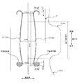
- FIG. 1 is a schematic cross-sectional view illustrating a configuration of a sanitary napkin 1. It is a figure which expands and represents the vaginal opening contact area hinge part.
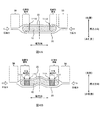
- FIG. 4A and FIG. 4B are diagrams specifically illustrating a state when a compressive force directed inward in the lateral direction is applied to the absorbent body 10 when the napkin 1 is used.
- FIG. 5A to FIG. 5C are diagrams for explaining modifications of the shape of the plane maintaining portion. It is a figure shown about the example at the time of changing arrangement
- FIG. It is a figure explaining the positional relationship of a plane maintenance part and 31 A of adhesion surfaces.
- An absorber that absorbs liquid a wing provided laterally outside the region in contact with the vaginal opening of the absorber; and a region in the longitudinal rear side of the region in contact with the vaginal opening of the absorber.
- An absorbent article comprising a hip flap portion provided on the outer side in the lateral direction, wherein the absorbent body includes a pair of first hinge portions formed along the longitudinal direction, and the pair of first pieces.
- a pair of second hinge portions formed to include the lateral component on the outside in the lateral direction from the one hinge portion, and on the outside in the lateral direction from the pair of first hinge portions,
- a pair of third hinge portions each including the vertical component, wherein at least a part of the first hinge portion, the second hinge portion, and the third hinge portion.
- the lateral width of the wing portion is maximum.
- Absorbent article in which the lateral width position and the hip flap portion made is arranged between the position of maximum, characterized in that
- the laterally outer region of the pair of first hinge portions formed on the absorbent body is easily maintained in a planar shape. For this reason, the absorbent body is irregularly deformed, and the lateral outer edge portion (for example, hip flap portion) is pulled inward in the laterally outer region of the pair of first hinge portions. It is suppressed that it cannot be covered firmly. This makes it difficult for the user to feel uncomfortable.
- an absorber that absorbs liquid a wing provided laterally outside the region that contacts the vaginal opening of the absorber, and a rear side in the vertical direction from the region that contacts the vaginal opening of the absorber
- a hip flap portion provided on the laterally outer side of the region, and an absorbent article comprising:
- the absorber is formed to include a pair of first hinge portions formed along the longitudinal direction and the lateral component on the outer side in the lateral direction from the pair of first hinge portions.
- a pair of second hinge portions including the lateral component at a position outside in the lateral direction from the pair of first hinge portions and at a position different from the second hinge portion in the longitudinal direction.
- a pair of third hinge portions formed respectively, wherein at least a part of the first hinge portion, the second hinge portion, and the third hinge portion are in the longitudinal direction of the absorber.
- the absorbent article is arranged between a position where the lateral width of the wing portion is maximum and a position where the lateral width of the hip flap portion is maximum. It becomes clear.
- the laterally outer region of the pair of first hinge portions formed on the absorbent body is easily maintained in a planar shape. It can be deformed irregularly, or the lateral outer edge portion (for example, hip flap portion) of the laterally outer region of the pair of first hinge portions can be pulled inward to firmly cover the user's skin. It is suppressed from disappearing. This makes it difficult for the user to feel uncomfortable.
- a central hinge portion is formed along the vertical direction on the rear side in the vertical direction of the first hinge portion, and the first hinge portion, the second hinge portion,
- at least a part of the inner region surrounded by the third hinge portion includes a position of the longitudinal rear end portion of the first hinge portion and the longitudinal front end portion of the central hinge portion. It is desirable that it is disposed between the two positions.
- first hinge part and the second hinge part are connected.
- the strength of the peripheral edge portion of the flat surface maintaining portion becomes high, so that even when a compressive force acts on the flat surface maintaining portion during use of the absorbent article, the flat surface maintaining portion is difficult to bend. .
- region of the horizontal direction outer side of a pair of 1st hinge part currently formed in the absorber can be maintained more easily in a planar shape.
- a plane maintaining part is provided in an inner region surrounded by at least a part of the first hinge part, the second hinge part, and the third hinge part. It is desirable that it is formed.
- the region in which the planar shape is easily maintained by surrounding at least three directions of the outer peripheral portion by the hinge portion including the vertical component and the hinge portion including the horizontal component. Since the (plane maintaining portion) is formed, it is possible to easily maintain the laterally outer region of the pair of first hinge portions formed on the absorbent body when the absorbent article is used.
- a pair of the plane maintaining portions is formed in the lateral direction, and a hinge portion extending in the lateral direction is disposed in a portion sandwiched between the pair of the plane maintaining portions. It is desirable that it is not.
- a pair of the plane maintaining portions are formed in the lateral direction, and the rigidity of the absorber in a portion sandwiched between the pair of plane maintaining portions is the vaginal opening. It is desirable that the rigidity of the absorber is lower than that in a portion sandwiched between the pair of first hinge portions in the abutting region.
- the central portion in the lateral direction of the absorbent body is easily deformed at the portion sandwiched between the pair of plane maintaining portions. Therefore, when a lateral compressive force acts on the absorbent body, it can be easily deformed so that the laterally central portion of the absorbent body is convex toward the user's skin. Thereby, a good fit can be given to the user.
- the absorbent body includes a pair of fourth hinge portions formed on the outer side in the lateral direction with respect to the pair of first hinge portions and including the lateral component, respectively.
- a pair of fifth hinge portions formed on the outer side in the lateral direction with respect to the pair of first hinge portions and including the vertical component, respectively, and at least one of the first hinge portions It is desirable that a part, the fourth hinge part, and the fifth hinge part are arranged on the front side in the longitudinal direction with respect to a region in contact with the vaginal opening.
- the horizontal interval between the pair of first hinge portions in the region of the central portion in the vertical direction of the first hinge portion is the end in the vertical direction of the first hinge portion. It is desirable that the distance is longer than the distance between the pair of first hinge portions in the region.
- an absorbent article it is possible to increase the area of the region that comes into contact with the user's vaginal opening, and it is possible to easily absorb blood drainage and the like when the absorbent article is used.
- one or more constricted portions are formed at the lateral edge of the hip flap portion.
- Such an absorbent article has a back sheet that covers the absorbent body from the non-skin side of a user, and an adhesive region coated with an adhesive is formed on the non-skin side surface of the back sheet.
- an adhesive region coated with an adhesive is formed on the non-skin side surface of the back sheet.
- at least a part of the first hinge part, a part of the area surrounded by the second hinge part and the third hinge part overlaps the adhesive area in the thickness direction. .
- a sanitary napkin 1 will be described as an example of an absorbent article according to the present embodiment.
- a sanitary napkin will be described as an example of the absorbent article.
- the absorbent article of the present embodiment also includes a so-called cage sheet (for example, a panty liner) and the like. It is not limited.
- FIG. 1 is a plan view illustrating the configuration of the sanitary napkin 1.
- FIG. 2 is a schematic cross-sectional view illustrating the configuration of the sanitary napkin 1.
- each direction is defined as shown in FIGS. That is, the direction along the product longitudinal direction of the sanitary napkin 1 is defined as “vertical direction”.
- the vertical direction has a “front side” and a “rear side”.
- the “front side” is a direction that becomes the ventral side of the user when the sanitary napkin 1 is used
- the “rear side” is a direction that becomes the back side of the user when the sanitary napkin 1 is used.
- a direction orthogonal to the vertical direction that is, a direction along the product width direction is referred to as a “lateral direction”.
- the direction perpendicular to the vertical direction and the horizontal direction is the “thickness direction”, and the side that contacts the wearer's skin (the upper side in FIG. 2) when wearing the sanitary napkin 1 is the “skin side” and the opposite side ( The lower side in FIG. 2 is defined as “non-skin side”.
- the sanitary napkin 1 (hereinafter also simply referred to as “napkin 1”) includes an absorbent body 10 that absorbs liquid, a top sheet 20 that covers the absorbent body 10 in the thickness direction from the user's skin side, It has the back sheet 30 which covers the absorber 10 from the skin side to the thickness direction, and the side flap 50 provided in the horizontal direction outer side of the absorber 10.
- the absorbent body 10 is a long and long member along the longitudinal direction, and includes hydrophilic fibers, pulp, and the like, and can efficiently absorb and retain fluids such as body fluids and blood drainage.
- the absorbent body 10 may be formed by laminating hydrophilic fibers or powders by the airlaid method, or may be an airlaid sheet obtained by forming hydrophilic fibers or powders into a sheet shape by the airlaid method.
- the top sheet 20 is a liquid-permeable sheet member that allows liquid such as body fluid to pass therethrough, and is formed of, for example, a nonwoven fabric.
- a member other than a non-woven fabric may be used as long as it is a sheet member having a structure that allows liquid to pass through and is a safe member when contacting the user's skin when the napkin 1 is used.
- a woven fabric or a mesh sheet may be used.
- the top sheet 20 is larger than the absorbent body 10 in the vertical direction and the horizontal direction, and can cover the entire region of the absorbent body 10.
- a second sheet 25 is provided between the top sheet 20 and the absorbent body 10 in the thickness direction.
- the second sheet 25 is configured by a member equivalent to the top sheet 20.
- top sheet 20 extends to the outside in the lateral direction of the absorbent body 10 to form a side flap 50 described later. Further, as shown in FIG. 2, the top sheet 20 is once folded inward in the lateral direction and then folded outward in the lateral direction again in a region overlapping with the region at both ends in the lateral direction of the absorbent body 10. It extends out in the lateral direction as it is. That is, the top sheet 20 is folded in the thickness direction in the regions at both ends in the lateral direction.
- the back sheet 30 is a non-liquid permeable sheet member.
- a breathable resin film is bonded to a non-woven fabric such as a film mainly composed of polyethylene or propylene, a breathable resin film, spunbond, or spunlace. Formed by a sheet. Since the back sheet 30 is non-liquid permeable, the liquid that permeates the top sheet 20 and is absorbed by the absorber 10 when the napkin 1 is used may ooze out to the clothing side (non-skin side) such as underwear. It is suppressed. It is desirable that the back sheet 30 has substantially the same shape as the top sheet 20 and has such flexibility that the user does not feel uncomfortable when using the napkin 1.
- a part of the back sheet 30 extends to the outside in the lateral direction of the absorbent body 10 similarly to the top sheet 20 to form a side flap 50 described later.
- an adhesive surface 31 ⁇ / b> A to which an adhesive such as a hot melt adhesive (hereinafter also referred to as HMA) is applied is formed at the center in the lateral direction of the non-skin side surface of the backsheet 30.
- adhesive surfaces 31B are formed on both lateral sides of the adhesive surface 31A (the non-skin side surface of the side flap 50) (see FIG. 2).
- the adhesive surfaces 31 ⁇ / b> A and 31 ⁇ / b> B are formed so that the napkin 1 is attached to the user's underwear when the napkin 1 is used so that the position does not shift.
- the adhesive surfaces 31A and 31B are covered with a packaging sheet 60 described later and a protective sheet (not shown). In the state covered with such a protective sheet, the adhesiveness of the adhesive surfaces 31A and 31B is not expressed.
- the side flaps 50 are formed by laminating the top sheet 20 and the back sheet 30 extending outward from both lateral sides of the absorbent body 10 in the thickness direction and bonding them together (see FIG. 2).
- the side flaps 50 may be formed of another member different from the top sheet 20 and the back sheet 30.
- a reinforcing sheet 55 for reinforcing the strength of the side flap 50 is provided between the top sheet 20 and the back sheet 30 in the thickness direction.
- the side flap 50 of the present embodiment includes a wing portion 51 extending outward in the lateral direction from a vaginal opening contact region provided closer to the front side than the longitudinal center of the absorber 10. , And a hip flap portion 52 extending outward in the lateral direction from the region in the longitudinal rear side of the vaginal opening contact region.
- the “vagina opening contact area” is an area that comes into contact with the user's vaginal opening when the napkin 1 is used (when worn).
- the wing portion 51 is bent to the non-skin side when the napkin 1 is used, and the adhesive surface 31B is affixed to the user's underwear, thereby making it difficult for the napkin 1 to be displaced in the crotch portion of the user.
- the hip flap portion 52 is provided so as to extend laterally outward on the longitudinal rear side (back side) of the napkin 1, and when the napkin 1 is used, the hip flap portion 52 is expanded in the lateral direction as shown in FIG. Can cover the buttocks widely. For example, even when blood drainage or the like wraps around the buttocks side while the user is lying on his / her back, the hip flap portion 52 covers the buttocks over a wide range, so that blood drainage or the like is not performed on the napkin 1. Prevents the user's underwear from getting dirty.
- constricted portions 52n are provided at the lateral edge of the hip flap portion 52.
- the constricted portion 52n is a portion formed in a meandering manner by alternately repeating a convex portion convex outward in the horizontal direction and a concave portion concaved outward in the horizontal direction in the vertical direction.
- a cooling sensation region CR in which particles of a cooling sensation agent are bonded by an adhesive such as HMA is formed.
- the side flap 50 is formed as a belt-like region extending in the vertical direction while having a predetermined width in the horizontal direction in the region outside the inner end portion in the horizontal direction.
- the cooling sensation region CR is formed on the non-skin side surface of the top sheet 20. That is, in this embodiment, the cooling sensation agent is provided between the top sheet 20 and the back sheet 30 stacked in the side flap 50.
- “Cool sensation agent” is a particle having a multiple capsule structure in which a chilling agent such as menthol or camphor is used as a core and the periphery thereof is covered with a water-soluble substance such as starch. In normal times, the cooling agent that is the core of the cooling sensation agent is not exposed to the outside. When a predetermined amount of moisture (for example, user's sweat or water vapor) comes into contact with the cooling sensation agent, the water-soluble substance dissolves and the internal cooling agent is released to the outside, which can give the user a refreshing feeling. .
- a refreshing sensation can be efficiently given to the user when the napkin 1 is stuffy due to sweat.
- the napkin 1 since the napkin 1 has a large area of the hip flap portion 52, it can cover the user's buttocks widely. On the other hand, when the napkin 1 is used for a long time, for example, when sleeping, the user's buttocks are stuffy. It tends to occur. Even in such a case, by providing the cool feeling region CR in the hip flap portion 52, it is possible to give the user a refreshing feeling and to reduce discomfort caused by stuffiness.
- a hinge portion 110 is formed on the surface of the absorbent body 10 (and the top sheet 20).
- the hinge part 110 is a linear part formed substantially along the vertical direction, and the absorber 10 is bent in the lateral direction with the hinge part 110 as a base point.
- a force that causes the absorbent body 10 to contract in the lateral direction is applied.
- the absorbent body 10 is bent with the hinge portion 110 as a base point, thereby absorbing the absorbent body 10.
- the hinge part 110 functions as a bending guide part of the absorber 10. Thereby, it becomes easy for the absorber 10 to maintain favorable liquid absorptivity.
- the hinge part 110 includes a vaginal opening contact area hinge part 111, a central hinge part 112, a rear hinge part 113, and a front hinge part 114.
- the vaginal opening contact area hinge 111 is formed so as to at least partially overlap the vaginal opening contact area of the absorbent body 10.
- the vaginal opening contact region is formed so as to straddle in the vertical direction.
- the central hinge portion 112 is formed in a region that is in contact with the vicinity of the user's anus on the rear side in the vertical direction with respect to the vaginal opening contact region hinge portion 111.
- the rear side hinge part 113 is formed in the area
- FIG. A pair of these hinge portions 111 to 113 are formed symmetrically with respect to the horizontal center line of the absorbent body 10.
- the front side hinge part 114 is formed in the area
- the hinge portions 111 to 114 are formed in a curved shape by arranging a plurality of compressed grooves formed by embossing or the like on the skin side surface of the absorber 10 (and the top sheet 20).
- embossing is actually given to the thickness direction of an absorber.
- a plurality of hole portions 120 are formed in a region sandwiched between the pair of hinge portions 111 to 113.
- the hole 120 is a hole that penetrates the top sheet 20 and the absorber 10 in the thickness direction.
- the rigidity of the absorber 10 is partially increased, and the absorber 10.
- the shape loss and kinking of are suppressed. That is, in the region where the hole 120 is formed, the absorber 10 is easily maintained in a planar shape as compared with the region where the hole 120 is not formed. Further, the provision of the hole portion 120 increases the air permeability when using the napkin 1 and has an effect of making it difficult to cause stuffiness.
- the region sandwiched between the pair of hinge portions 110 maintains a planar shape and is convex to the skin side.
- the arrangement and quantity of the holes 120 are determined so that the following deformation is possible.
- FIG. 3 is an enlarged view of the vaginal opening contact area hinge portion 111.
- the hinge part 111 is formed by a first hinge part 111A, a second hinge part 111B, and a third hinge part 111C.
- the first hinge portion 111A is a portion formed along the vertical direction.
- the first hinge portion 111A is arranged in a curve so as to spread outward in the lateral direction at the central portion in the vertical direction. Therefore, the length of the portion sandwiched between the pair of first hinge portions 111A (the interval between the hinges) is a region at both longitudinal ends of the first hinge portion 111A (formed by the second hinge portion 111B and the third hinge portion 111C).
- the hinge interval 111WL in the central portion in the vertical direction is longer than the hinge interval 111WS in the region (111WL> 111WS). That is, the area of the region sandwiched between the pair of first hinge portions 111A is large at the longitudinal center portion of the first hinge portion 111A.
- the area of the region sandwiched between the pair of first hinge portions 111A is small at both longitudinal ends of the first hinge portion 111A. This makes it possible to increase the area of the plane maintaining portion described later.
- the 2nd hinge part 111B is a part currently formed toward the outer side of the horizontal direction in the vertical direction edge part area
- the second hinge portion 111B is a hinge portion that is formed so as to include a lateral component in a region laterally outward from the first hinge portion 111A.
- the third hinge portion 111C is a portion formed in the vertical direction in the laterally outer end region of the second hinge portion 111B.
- the third hinge portion 111C is a hinge portion that is formed so as to include a vertical component in a region laterally outward from the first hinge portion 111A.
- the first hinge portion 111A, the second hinge portion 111B, and the third hinge portion 111C are substantially arc-shaped. The curve is formed.
- a “plane maintaining portion” as shown by the hatched lines in FIG. 3 is formed.
- the plane maintaining unit has at least three directions (two in the vertical direction and one in the horizontal direction, or the vertical direction) in the outer peripheral part by the hinge part including the vertical component and the hinge part including the horizontal component.
- the flat surface maintaining portion is formed in the laterally outer region of the pair of hinge portions 110 (here, the first hinge portion 111A) of the absorber 10.
- the hole 120 is not formed in the laterally outer region of the pair of first hinge portions 111A, and the laterally inner region of the pair of first hinge portions 111A (the region in which the hole 120 is formed). ),
- the rigidity of the absorber is low. Accordingly, when a force that compresses the absorbent body 10 inward in the lateral direction is applied when the napkin 1 is used (when worn), the laterally outer region of the pair of first hinge portions 111A in the absorbent body 10 is compressed. It will be crushed easily.
- this region is also referred to as “low-rigid region”.
- the hip flap portion 52 of the side flap portion 50 provided on the outer side in the lateral direction is pulled inward in the lateral direction and contracts, so that the user's buttocks are sufficiently worn when the napkin 1 is worn. May not be able to be covered. Furthermore, when the hip flap portion 52 contracts, the cooling sensation region CR also contracts, which may make it difficult to give the user a refreshing feeling. Further, when the napkin 1 is used, the absorbent body 10 is gently deformed so as to protrude toward the user's skin side by a compressive force directed inward in the lateral direction (see FIG. 4B described later), and a good fit for the user. It is ideal to give a feeling.
- the absorbent body 10 is ideally deformed by the fact that the compressive force does not act up to the absorbent body 10 or the non-uniform compressive force acts on the absorbent body 10 conversely. There is a risk that it will not be possible.
- a plane maintaining portion is provided at a predetermined position in the low-rigidity area of the absorbent body 10 so that the area is not easily crushed.
- a plane maintaining portion is disposed between the position 52WL (see FIG. 1).
- at least a part of the first hinge part 111A, the second hinge part 111B, and the third hinge part 111C are arranged between 51WL and 52WL in the vertical direction.
- the side flap 50 (hip flap portion 52) disposed on the laterally outer side of the planar maintaining portion is pulled inward in the lateral direction. Since it becomes difficult for a force to act, it can control effectively that hip flap part 52 contracts.
- FIG. 4A and FIG. 4B are diagrams specifically illustrating a state when a compressive force directed inward in the lateral direction acts on the absorbent body 10 when the napkin 1 of the present embodiment is used.
- FIG. 4A is a cross-sectional view of a comparative example illustrating a case where the absorber 10 is not provided with a plane maintaining portion.
- FIG. 4B is a cross-sectional view of the napkin 1 of the present embodiment that represents the case where the absorber 10 is provided with a plane maintaining portion.
- the plane maintaining portion is formed in the low-rigidity region, the low-rigidity region is not easily crushed even if a compressive force is applied, so the side flap 50 (hip flap portion 52) It is difficult to be pulled inward in the direction, and the entire width (lateral length) is suppressed from being narrowed. Therefore, the hip flap part 52 can cover a user's body widely.
- the compressive force toward the inner side in the lateral direction is transmitted to the region in the central portion in the lateral direction of the absorbent body 10 through the plane maintaining portion. Thereby, it deform
- the above-described compressive force toward the inside in the lateral direction tends to be particularly large in the vaginal opening contact region. This is because when the napkin 1 is used, the vaginal opening contact area is sandwiched between the groin parts of the user, and a large force is generated in the area. When such a large compressive force acts on the absorbent body 10, there is a risk that the contraction of the hip flap 52 will also increase. Therefore, in order to suppress the contraction of the hip flap 52, it is important not to transmit the influence of the large compressive force generated in the vaginal opening contact area to the hip flap 52. Therefore, it is desirable that the plane maintaining portion is provided at a position as close as possible to the vaginal opening contact region in the region where the hip flap portion 52 is formed in the vertical direction.
- the plane maintaining portion is disposed between the longitudinal rear end portion of the first hinge portion 111A and the longitudinal front end portion of the central hinge portion 112. That is, the plane maintaining part is provided so that a part of the region between the region that contacts the user's vaginal opening and the region that contacts the user's anus when the napkin 1 is used overlaps. As shown in FIG. 1, this region is a region closer to the vaginal opening contact region in the vertical direction among the regions where the hip flap portions 52 are formed. Therefore, by providing the plane maintaining portion in the area, it is easy to suppress a large compressive force generated in the vaginal opening contact area from acting on the hip flap portion 52. That is, when the napkin 1 is used, it is possible to effectively suppress the width of the hip flap 52 from being narrowed.
- first hinge portion 111A, the second hinge portion 111B, and the third hinge portion 111C that constitute the outer periphery of the plane maintaining portion are connected to each other.
- first hinge part 111A and the second hinge part 111B are not connected, a gap is formed between the first hinge part 111A and the second hinge part 111B. That is, a cut is formed at the periphery of the plane maintaining portion.
- the flat surface maintaining portion is easily bent at the cut portion of the peripheral edge, and the low rigidity region of the absorbent body 10 is maintained in a flat shape.
- the hinge portions extending in the vertical direction and the horizontal direction are connected to each other, the strength of the peripheral edge portion of the plane maintaining portion is increased, and the planar shape can be easily maintained in the low rigidity region of the absorbent body 10. Can do. Therefore, it is desirable that at least the first hinge portion 111A extending in the vertical direction and the second hinge portion 111B extending in the horizontal direction are connected to each other.
- the hinge part extended in a horizontal direction is not arrange
- the plane maintaining part is formed at the lower end in the vertical direction of the first hinge part 111A, but as shown in FIG. You may make it form in a direction upper end part. That is, the 4th hinge part 111D and the 5th hinge part 111E may be arrange
- the fourth hinge portion 111D is a hinge corresponding to the second hinge portion 111B, and is formed so as to include a lateral component in a region laterally outward from the first hinge portion 111A.
- the fifth hinge portion 111E is a hinge corresponding to the third hinge portion 111C, and is formed in the longitudinal direction in the laterally outer end region of the fourth hinge portion 111D.
- FIG. 5A to FIG. 5C are diagrams for explaining modifications of the shape of the plane maintaining portion.
- FIG. 5A shows an example in which a rectangular plane maintaining portion is formed by the first hinge portion 111A, the second hinge portion 111B, and the third hinge portion 111C.
- the 2nd hinge part 111B is formed in the linear form extended in a horizontal direction
- the 3rd hinge part 111C is formed in the linear form extended in a vertical direction.
- a plane maintaining part is formed in an inner region surrounded by a part of the first hinge part 111A, the second hinge part 111B, and the third hinge part 111C.
- FIG. 5B shows an example in which the plane maintaining portion is formed away from the hinge portion.
- the first hinge portion 111 ⁇ / b> A is formed on the laterally outer side of the vaginal opening contact region hinge portion 111 as a hinge portion different from the vaginal opening contact region hinge portion 111.
- a plane maintaining part is formed in an inner region surrounded by the first hinge part 111A, the second hinge part 111B, and the third hinge part 111C.
- FIG. 5C shows an example of a plane maintaining portion formed when the third hinge portion 111C is a hinge extending in the lateral direction.
- the third hinge portion 111C is formed to include a lateral component at a position laterally outward from the first hinge portion 111A and at a different position in the vertical and horizontal directions from the second hinge portion 111B.
- a plane maintaining part is formed in an inner region surrounded by a part of the first hinge part 111A, the second hinge part 111B, and the third hinge part 111C.
- the plane maintenance area has a shape as shown in the modified examples of FIGS. 5A to 5C, the low synthesis area of the absorber 10 can be easily maintained in a plane shape. That is, even when a compressive force directed inward in the lateral direction acts on the absorbent body 10, the flat surface maintenance region is not easily crushed, so that the side flap 50 is prevented from being pulled and contracted. The Moreover, it becomes easy to make the horizontal direction center part of the absorber 10 deform
- the plurality of hole portions 120 are formed in the region sandwiched between the pair of hinge portions 110.
- the hole portion 120 is formed in the region sandwiched between the pair of hinge portions 110.
- a region that is formed and a region that is not formed may be provided.
- the rigidity of the absorber 10 is lower than that in the region where the hole 120 is formed. Therefore, the rigidity of the absorber 10 can be increased by changing the arrangement and number of the holes 120. Can be partially adjusted.
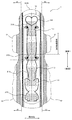
- FIG. 6 is a diagram illustrating an example where the arrangement of the holes 120 is modified by the napkin 1.
- the hole 120 is not formed in at least a part of the region sandwiched between the plane maintaining portions formed in the pair of vaginal opening contact region hinges 111.
- the hole 120 is not formed in the blank region 120b in the central portion in the horizontal direction surrounded by the broken line in FIG. 6 among the regions sandwiched between the pair of plane maintaining portions.
- a hole 120 is formed in an area sandwiched between the pair of vaginal opening contact area hinges 111.
- the rigidity of the portion sandwiched between the pair of vaginal opening contact region hinge portions 111 in the vaginal opening contact region of the absorbent body 10 is the portion sandwiched between the pair of plane maintaining portions of the absorbent body 10 ( This is lower than the rigidity of the blank area 120b.
- the rigidity of the absorbent body 10 is low, deformation is likely to occur when an external force is applied to the absorbent body 10, so in the example of FIG. 6, absorption is performed at a portion sandwiched between a pair of plane maintaining portions. The central part in the horizontal direction of the body 10 is easily deformed.
- the stiffness of the absorbent body 10 in the blank area 120b may be lowered by changing the basis weight of the absorbent body 10.
- ⁇ Adhesive surface 31A> In the above-described embodiment, it has been described that the adhesive surface 31A is formed on the non-skin side surface of the backsheet 30. However, the position where the adhesive surface 31A is formed and the position where the plane maintaining portion is formed. By adjusting, the absorber 10 can be easily maintained in a planar shape.
- FIG. 7 is a diagram for explaining the positional relationship between the flat surface maintaining portion and the adhesive surface 31A.
- the overlapping area is an area that is affixed and fixed to the user's underwear when the napkin 1 is used, the planar shape can be easily maintained due to the rigidity of the underwear fabric even when an external force such as a compressive force is applied. .
- the positional relationship with the undergarment is difficult to shift in some areas, not the entire plane maintaining part, it is easy to follow the movement even when the user moves the body, and a large load is applied to the plane maintaining part. This can be suppressed.
- sanitary napkins 1 sanitary napkins (napkins), 10 Absorber, 20 Top sheet, 25 second seat, 30 back sheet, 31A adhesive surface, 31B adhesive surface, 50 side flaps, 51 Wing part, 51WL Longitudinal position, 52 hip flap part, 52n constricted part, 52WL longitudinal position, 55 Reinforcement sheet, 60 packaging sheet, 61 fixing tape, 110 hinge part, 111 Vaginal opening contact area hinge part, 111A 1st hinge part, 111B 2nd hinge part, 111C 3rd hinge part, 111D 4th hinge part, 111E 5th hinge part, 111WL hinge spacing, 111WS hinge spacing, 112 central hinge, 113 Rear hinge part, 114 Front hinge part, 120 hole, 120b blank area, CR cold feeling area
Landscapes
- Health & Medical Sciences (AREA)
- Epidemiology (AREA)
- Engineering & Computer Science (AREA)
- Biomedical Technology (AREA)
- Heart & Thoracic Surgery (AREA)
- Vascular Medicine (AREA)
- Life Sciences & Earth Sciences (AREA)
- Animal Behavior & Ethology (AREA)
- General Health & Medical Sciences (AREA)
- Public Health (AREA)
- Veterinary Medicine (AREA)
- Absorbent Articles And Supports Therefor (AREA)
Abstract
液体を吸収する吸収体(10)と、前記吸収体の膣口と当接する領域の横方向外側に設けられたウイング部(51)と、前記吸収体(10)の前記膣口と当接する領域よりも縦方向後側の領域の前記横方向外側に設けられたヒップフラップ部(52)と、を備える吸収性物品(1)であって、前記吸収体(10)は、前記縦方向に沿って形成される1対の第1ヒンジ部(111A)と、前記1対の第1ヒンジ部(111A)よりも前記横方向の外側に、前記横方向の成分を含んでそれぞれ形成される1対の第2ヒンジ部(111B)と、前記1対の第1ヒンジ部(111A)よりも前記横方向の外側に、前記縦方向の成分を含んでそれぞれ形成される1対の第3ヒンジ部(111C)と、を有し、前記第1ヒンジ部(111A)の少なくとも一部と、前記第2ヒンジ部(111B)と、前記第3ヒンジ部(111C)とが、前記吸収体(10)の前記縦方向において、前記ウイング部(51)の前記横方向の幅が最大となる位置(51WL)と前記ヒップフラップ部(52)の前記横方向の幅が最大となる位置(52WL)との間に配置されている。
Description
本発明は、吸収性物品に関する。
生理用ナプキン等の吸収性物品の着用時において、該吸収性物品に対して横方向(幅方向)の中央部に向かう圧縮力が作用する場合がある。このような圧縮力が作用したときに吸収体が不規則に変形して型崩れやよれが生じることにより、吸収性物品の吸収性能が十分に発揮されなくなるおそれがある。これに対して、吸収性物品の横方向外側の位置に製品縦方向に伸びる溝部(ヒンジ)を設けておき、横方向の中央部に向かう圧縮力が作用したときに当該溝部に沿って吸収体を変形させることで、型崩れ等を生じにくくする吸収性物品が開示されている(例えば特許文献1)。
特許文献1に記載された吸収性物品では、溝部に沿って吸収体を変形させることが可能である一方、溝部から外れた低剛性領域では吸収体が潰れて平面形状を維持できなくなる場合ある。そのため、吸収性物品の着用時において吸収体の良好な変形が望めなくなるおそれがある。また、低剛性領域が潰れてしまうことにより吸収性物品の横方向外縁部(例えば使用者の臀部を覆うヒップフラップ)が内側に引っ張られて使用者の身体を適切に覆うことができなくなり、使用者に不快感を与えるおそれがある。
本発明は、上記のような問題に鑑みてなされたものであって、その目的とするところは、使用時に吸収体の低剛性領域が平面形状に維持されやすい吸収性物品を提供することにある。
上記目的を達成するための主たる発明は、液体を吸収する吸収体と、前記吸収体の膣口と当接する領域の横方向外側に設けられたウイング部と、前記吸収体の前記膣口と当接する領域よりも縦方向後側の領域の前記横方向外側に設けられたヒップフラップ部と、を備える吸収性物品であって、前記吸収体は、前記縦方向に沿って形成される1対の第1ヒンジ部と、前記1対の第1ヒンジ部よりも前記横方向の外側に、前記横方向の成分を含んでそれぞれ形成される1対の第2ヒンジ部と、前記1対の第1ヒンジ部よりも前記横方向の外側に、前記縦方向の成分を含んでそれぞれ形成される1対の第3ヒンジ部と、を有し、前記第1ヒンジ部の少なくとも一部と、前記第2ヒンジ部と、前記第3ヒンジ部とが、前記吸収体の前記縦方向において、前記ウイング部の前記横方向の幅が最大となる位置と前記ヒップフラップ部の前記横方向の幅が最大となる位置との間に配置されている、ことを特徴とする吸収性物品である。
本発明の他の特徴については、本明細書及び添付図面の記載により明らかにする。
本発明の他の特徴については、本明細書及び添付図面の記載により明らかにする。
本発明によれば、吸収性物品を使用する際に、吸収体の低剛性領域が平面形状に維持されやすくなり、使用者に不快感を与えにくくすることができる。
本明細書及び添付図面の記載により、少なくとも以下の事項が明らかとなる。
液体を吸収する吸収体と、前記吸収体の膣口と当接する領域の横方向外側に設けられたウイング部と、前記吸収体の前記膣口と当接する領域よりも縦方向後側の領域の前記横方向外側に設けられたヒップフラップ部と、を備える吸収性物品であって、前記吸収体は、前記縦方向に沿って形成される1対の第1ヒンジ部と、前記1対の第1ヒンジ部よりも前記横方向の外側に、前記横方向の成分を含んでそれぞれ形成される1対の第2ヒンジ部と、前記1対の第1ヒンジ部よりも前記横方向の外側に、前記縦方向の成分を含んでそれぞれ形成される1対の第3ヒンジ部と、を有し、前記第1ヒンジ部の少なくとも一部と、前記第2ヒンジ部と、前記第3ヒンジ部とが、前記吸収体の前記縦方向において、前記ウイング部の前記横方向の幅が最大となる位置と前記ヒップフラップ部の前記横方向の幅が最大となる位置との間に配置されている、ことを特徴とする吸収性物品
液体を吸収する吸収体と、前記吸収体の膣口と当接する領域の横方向外側に設けられたウイング部と、前記吸収体の前記膣口と当接する領域よりも縦方向後側の領域の前記横方向外側に設けられたヒップフラップ部と、を備える吸収性物品であって、前記吸収体は、前記縦方向に沿って形成される1対の第1ヒンジ部と、前記1対の第1ヒンジ部よりも前記横方向の外側に、前記横方向の成分を含んでそれぞれ形成される1対の第2ヒンジ部と、前記1対の第1ヒンジ部よりも前記横方向の外側に、前記縦方向の成分を含んでそれぞれ形成される1対の第3ヒンジ部と、を有し、前記第1ヒンジ部の少なくとも一部と、前記第2ヒンジ部と、前記第3ヒンジ部とが、前記吸収体の前記縦方向において、前記ウイング部の前記横方向の幅が最大となる位置と前記ヒップフラップ部の前記横方向の幅が最大となる位置との間に配置されている、ことを特徴とする吸収性物品
このような吸収性物品によれば、吸収性物品の使用時において吸収体に形成されている1対の第1ヒンジ部の横方向外側の領域が平面形状に維持されやすくなる。そのため、吸収体が不規則に変形することや、当該1対の第1ヒンジ部の横方向外側の領域において横方向外縁部(例えばヒップフラップ部)が内側に引っ張られることにより使用者の肌をしっかりと覆うことができなくなることが抑制される。これにより、使用者に不快感を与えにくくなる。
また、液体を吸収する吸収体と、前記吸収体の膣口と当接する領域の横方向外側に設けられたウイング部と、前記吸収体の前記膣口と当接する領域よりも縦方向後側の領域の前記横方向外側に設けられたヒップフラップ部と、を備える吸収性物品であって、
前記吸収体は、前記縦方向に沿って形成される1対の第1ヒンジ部と、前記1対の第1ヒンジ部よりも前記横方向外側に、前記横方向の成分を含んでそれぞれ形成される1対の第2ヒンジ部と、前記1対の第1ヒンジ部よりも前記横方向外側、かつ、前記第2ヒンジ部とは前記縦方向の異なる位置に、前記横方向の成分を含んでそれぞれ形成される1対の第3ヒンジ部と、を有し、前記第1ヒンジ部の少なくとも一部と、前記第2ヒンジ部と、前記第3ヒンジ部とが、前記吸収体の前記縦方向において、前記ウイング部の前記横方向の幅が最大となる位置と前記ヒップフラップ部の前記横方向の幅が最大となる位置との間に配置されている、ことを特徴とする吸収性物品が明らかとなる。
前記吸収体は、前記縦方向に沿って形成される1対の第1ヒンジ部と、前記1対の第1ヒンジ部よりも前記横方向外側に、前記横方向の成分を含んでそれぞれ形成される1対の第2ヒンジ部と、前記1対の第1ヒンジ部よりも前記横方向外側、かつ、前記第2ヒンジ部とは前記縦方向の異なる位置に、前記横方向の成分を含んでそれぞれ形成される1対の第3ヒンジ部と、を有し、前記第1ヒンジ部の少なくとも一部と、前記第2ヒンジ部と、前記第3ヒンジ部とが、前記吸収体の前記縦方向において、前記ウイング部の前記横方向の幅が最大となる位置と前記ヒップフラップ部の前記横方向の幅が最大となる位置との間に配置されている、ことを特徴とする吸収性物品が明らかとなる。
このような吸収性物品によれば、吸収性物品の使用時に、吸収体に形成されている1対の第1ヒンジ部の横方向外側の領域が平面形状に維持されやすくなるため、吸収体が不規則に変形することや、当該1対の第1ヒンジ部の横方向外側の領域の横方向外縁部(例えばヒップフラップ部)が内側に引っ張られて使用者の肌をしっかりと覆うことができなくなることが抑制される。これにより、使用者に不快感を与えにくくなる。
かかる吸収性物品であって、前記第1ヒンジ部の前記縦方向後側には、前記縦方向に沿って中央ヒンジ部が形成されており、前記第1ヒンジ部と、前記第2ヒンジ部と、前記第3ヒンジ部とで囲まれた内側の領域のうち、少なくとも一部は、前記第1ヒンジ部の前記縦方向後側端部の位置と、前記中央ヒンジ部の前記縦方向前側端部の位置との間に配置されている、ことが望ましい。
このような吸収性物品によれば、吸収性物品の着用時において、使用者の鼠径部間に挟まれることによって該吸収性物品の膣口当接領域に対して大きな圧縮力が作用したとしても、そのような力がヒップフラップ部に作用することを抑制しやすくなる。これにより、ヒップフラップ部の幅が狭くなることを抑制しやすくなる。
かかる吸収性物品であって、前記第1ヒンジ部と前記第2ヒンジ部とが繋がっている、ことが望ましい。
このような吸収性物品によれば、平面維持部の周縁部の強度が高くなることにより、吸収性物品の使用時に平面維持部に圧縮力が作用した場合でも、該平面維持部が撓みにくくなる。これにより、吸収体に形成されている1対の第1ヒンジ部の横方向外側の領域をより平面形状に維持しやすくすることができる。
かかる吸収性物品であって、前記吸収体で、前記第1ヒンジ部の少なくとも一部と、前記第2ヒンジ部と、前記第3ヒンジ部とで囲まれた内側の領域に、平面維持部が形成されている、ことが望ましい。
このような吸収性物品によれば、縦方向の成分を含むヒンジ部と横方向の成分を含むヒンジ部とによって、外周部のうちの少なくとも3方向を囲まれることによって平面形状を維持しやすい領域(平面維持部)が形成されるため、吸収性物品の使用時において吸収体に形成されている1対の第1ヒンジ部の横方向外側の領域を平面形状に保ちやすくすることができる。
かかる吸収性物品であって、前記平面維持部が、前記横方向に1対形成されており、1対の前記平面維持部の間に挟まれる部分には、前記横方向に伸びるヒンジ部が配置されていない、ことが望ましい。
このような吸収性物品によれば、吸収性物品の使用時における吸収体の良好な変形(吸収体の横方向中央部が使用者の肌側に凸となるような変形)が阻害されにくくなる。これにより、使用者に良好なフィット感を与えることができる。
かかる吸収性物品であって、前記平面維持部が、前記横方向に1対形成されており、1対の前記平面維持部の間に挟まれる部分における前記吸収体の剛性は、前記膣口と当接する領域中で1対の前記第1ヒンジ部の間に挟まれる部分における前記吸収体の剛性よりも低い、ことが望ましい。
このような吸収性物品によれば、1対の平面維持部の間に挟まれる部分において吸収体の横方向中央部が変形しやすくなる。したがって、吸収体に対して横方向の圧縮力が作用した場合に、吸収体の横方向中央部が使用者の肌側に凸となるように変形させやすくすることができる。これにより、使用者に良好なフィット感を与えることができる。
かかる吸収性物品であって、前記吸収体は、前記1対の第1ヒンジ部よりも前記横方向の外側に、前記横方向の成分を含んでそれぞれ形成される1対の第4ヒンジ部と、前記1対の第1ヒンジ部よりも前記横方向の外側に、前記縦方向の成分を含んでそれぞれ形成される1対の第5ヒンジ部と、を有し、前記第1ヒンジ部の少なくとも一部と、前記第4ヒンジ部と、前記第5ヒンジ部とが、前記膣口と当接する領域よりも前記縦方向の前側に配置されている、ことが望ましい。
このような吸収性物品によれば、膣口当接領域で発生する圧縮力の影響が吸収体の前側の領域に及ぶことを抑制しやすくなる。これにより、吸収性物品の使用者の下腹部と当接する領域の収縮が抑制され、使用者により良好なフィット感を与えることができる。
かかる吸収性物品であって、前記第1ヒンジ部の前記縦方向の中央部の領域における前記1対の第1ヒンジ部の横方向の間隔は、前記第1ヒンジ部の前記縦方向の端部の領域における前記1対の第1ヒンジ部の横方向の間隔よりも長い、ことが望ましい。
このような吸収性物品によれば、使用者の膣口と当接する領域の面積を広くとることが可能となり、吸収性物品の使用時において排血等を吸収しやすくすることができる。また、平面維持部の面積を広くとることが可能となり、吸収体に形成されている1対の第1ヒンジ部の横方向外側の領域を平面形状に維持しやすくなる。
かかる吸収性物品であって、前記ヒップフラップ部の前記横方向の端縁部には、1以上のくびれ部が形成されている、ことが望ましい。
このような吸収性物品によれば、ヒップフラップ部に収縮やよれが発生したとしても、くびれ部において力が分散されるため、ヒップフラップ部の他の領域に収縮やよれの影響が伝播するのを抑制することができる。したがって、ヒップフラップ部が広範囲に亘って収縮してしまうことを抑制しやすくなる。
かかる吸収性物品であって、前記吸収体を使用者の非肌側から覆うバックシートを有し、前記バックシートの前記非肌側の表面には接着剤が塗布された粘着領域が形成されており、前記第1ヒンジ部の少なくとも一部と、前記第2ヒンジ部と、前記第3ヒンジ部とによって囲まれる領域の一部が、厚さ方向について、前記粘着領域と重複する、ことが望ましい。
このような吸収性物品によれば、ヒンジ部によって囲まれる領域(平面維持部)の一部が粘着領域によって下着に固定されるため、圧縮力等の外力が作用した場合であっても下着の生地の剛性により平面形状を保ちやすくなる。また、使用者が身体を動かした場合などでも吸収体がその動きに追従しやすくなるので、ヒンジ部によって囲まれる領域に大きな負荷がかかることを抑制できる。
===実施形態===
<生理用ナプキンの構成>
本実施形態に係る吸収性物品の一例として、生理用ナプキン1について説明する。なお、以下の説明では吸収性物品の例として生理用ナプキンについて説明するが、本実施形態の吸収性物品には、所謂おりものシート(例えばパンティライナー)等も含まれており、生理用ナプキンに限定されるものではない。
<生理用ナプキンの構成>
本実施形態に係る吸収性物品の一例として、生理用ナプキン1について説明する。なお、以下の説明では吸収性物品の例として生理用ナプキンについて説明するが、本実施形態の吸収性物品には、所謂おりものシート(例えばパンティライナー)等も含まれており、生理用ナプキンに限定されるものではない。
図1は、生理用ナプキン1の構成を説明する平面図である。図2は、生理用ナプキン1の構成を説明する概略断面図である。また、以下の説明では、図1及び図2に示すように、各方向を定義する。すなわち、生理用ナプキン1の製品長手方向に沿った方向を「縦方向」とする。縦方向は「前側」と「後側」を有する。この「前側」は生理用ナプキン1の使用時において使用者の腹側となる方向であり、「後側」は生理用ナプキン1の使用時において使用者の背側となる方向である。また、縦方向と直交する方向、すなわち製品幅方向に沿った方向を「横方向」とする。また、縦方向及び横方向と直交する方向を「厚さ方向」とし、生理用ナプキン1の着用時に着用者の肌と当接する側(図2において上側)を「肌側」、その逆側(図2において下側)を「非肌側」とする。
生理用ナプキン1(以下、単に「ナプキン1」とも呼ぶ)は、液体を吸収する吸収体10と、使用者の肌側から厚さ方向に吸収体10を覆うトップシート20と、使用者の非肌側から厚さ方向に吸収体10を覆うバックシート30と、吸収体10の横方向外側に設けられたサイドフラップ50とを有する。また、ナプキン1の肌側表面には、ヒンジ部110と孔部120とが形成されている。
吸収体10は、縦方向に沿って長い縦長の部材であり、親水性繊維やパルプ等を含み、体液や排血等の液体を効率的に吸収・保持することができる。吸収体10は、親水性繊維又は紛体をエアレイド法によって積層して形成されても良いし、親水性繊維又は紛体をエアレイド法によってシート状に成形したエアレイドシートであっても良い。
トップシート20は、体液等の液体を透過させる液透過性のシート部材であり、例えば不織布によって形成される。但し、液体を透過する構造のシート部材であり、かつ、ナプキン1の使用時において使用者の肌と当接する際に安全な部材であれば不織布以外の部材が使用されていても良い。例えば、織布やメッシュシートであっても良い。トップシート20は縦方向及び横方向において吸収体10よりも大きく、吸収体10の全領域を覆うことができる。また、トップシート20と吸収体10との厚さ方向の間には、セカンドシート25が設けられている。セカンドシート25は、トップシート20と同等の部材によって構成される。
トップシート20の一部は、吸収体10の横方向外側に延出することにより、後述するサイドフラップ50を形成する。また、図2に示されるようにトップシート20は、吸収体10の横方向両端部の領域と厚さ方向に重複する領域において、一旦横方向内側に折り返された後、再び横方向外側に折り返されてそのまま横方向外側に延出している。すなわち、トップシート20は横方向両端部の領域において厚さ方向に折り重ねられた状態となっている。
バックシート30は、非液透過性のシート部材であり、例えばポリエチレンやプロピレン等を主体としたフィルム、通気性の樹脂フィルム、スパンボンド、又はスパンレース等の不織布に通気性の樹脂フィルムが接合されたシートなどによって形成される。バックシート30が非液透過性であることから、ナプキン1の使用時においてトップシート20を透過して吸収体10によって吸収された液体が下着等の着衣側(非肌側)に染み出すことが抑制される。バックシート30は、トップシート20とほぼ同一の形状であり、ナプキン1の使用時において使用者に違和感を生じさせない程度の柔軟性を有することが望ましい。
バックシート30の一部は、トップシート20と同様に吸収体10の横方向外側に延出することにより、後述するサイドフラップ50を形成する。また、バックシート30の非肌側表面の横方向中央部には、ホットメルト接着剤(以下、HMAとも呼ぶ)等の接着剤が塗布された粘着面31Aが形成されている。同様に、粘着面31Aの横方向両側部(サイドフラップ50の非肌側表面)には粘着面31Bが形成されている(図2参照)。粘着面31A及び31Bは、ナプキン1の使用時においてナプキン1を使用者の下着に貼付して位置がずれないようにするために形成される。なお、ナプキン1の不使用時には、粘着面31A及び31Bが、後述する包装シート60や不図示の保護シートによって覆われている。このような保護シートに覆われている状態では、粘着面31A及び31Bの粘着性は発現しない。
サイドフラップ50は、吸収体10の横方向両側部から外側に延出したトップシート20及びバックシート30を厚さ方向に積層して互いに接合することにより形成されている(図2参照)。但し、サイドフラップ50がトップシート20及びバックシート30とは異なる別の部材によって形成されているのであっても良い。また、トップシート20とバックシート30との厚さ方向の間には、サイドフラップ50の強度を補強するための補強シート55が設けられている。
本実施形態のサイドフラップ50は、図1に示されるように、吸収体10の縦方向中央よりも前側寄りに設けられた膣口当接領域から横方向の外側に延出するウイング部51と、該膣口当接領域よりも縦方向後側の領域から横方向の外側に延出するヒップフラップ部52とを有する。なお、「膣口当接領域」は、ナプキン1の使用時(着用時)において使用者の膣口と当接する領域である。
ウイング部51は、ナプキン1の使用時に非肌側に折り曲げられ、粘着面31Bが使用者の下着に貼付されることにより、使用者の股間部においてナプキン1の位置ずれを生じにくくする。
ヒップフラップ部52は、ナプキン1の縦方向後側(背側)において横方向外側に延出して設けられ、ナプキン1の使用時には図1のように横方向に展開した状態となって使用者の臀部を広く覆うことができる。例えば、使用者が仰向けに寝ている状態で排血等が臀部側に回り込むような場合であっても、ヒップフラップ部52が広範囲に亘って臀部を覆っているため、排血等がナプキン1の外側に漏出しにくくなり、使用者の下着が汚れることを抑制する。
また、ヒップフラップ部52の横方向端縁部には、図1に示されるような複数のくびれ部52nが設けられている。くびれ部52nは、横方向外側に凸となった凸部と横方向外側に凹となった凹部とが縦方向において交互に繰り返されることによって蛇行状に形成された部位である。詳細は後述するが、ナプキン1の使用時において、吸収体10に対して横方向内側に向かう圧縮力が作用すると、ヒップフラップ部52が横方向内側に引っ張られて収縮したり、ヒップフラップ部52の表面によれが発生したりするおそれがある。これに対して、ヒップフラップ部52の横方向端縁部が蛇行状に形成されていることにより、収縮やよれが発生したとしても、当該くびれ部52nにおいて力が分散され、ヒップフラップ部52の他の領域に収縮やよれの影響が伝播するのを抑制することができる。すなわち、ヒップフラップ部52の全体が収縮したりよれたりすることを抑制しやすくなる。
サイドフラップ50(ウイング部51、及びヒップフラップ部52)の所定の領域には、HMA等の接着剤によって冷感剤の粒子が接合された冷感領域CRが形成されている。具体的には、図1に示されるようにサイドフラップ50の横方向の内側端部よりも外側の領域に、横方向に所定の幅を有しつつ縦方向に伸びる帯状の領域として形成される。また、図2に示されるように、冷感領域CRはトップシート20の非肌側表面に形成されている。つまり、本実施形態では、サイドフラップ50において積層されているトップシート20とバックシート30との厚さ方向の間に冷感剤が設けられている。これにより、冷感剤と使用者の肌との直接の接触が抑制されるため、使用者に過度の刺激を与えにくくなる。
「冷感剤」は、メントールやカンファー等の清涼剤を核として、その周囲をでんぷん等の水溶性物質によって覆われた多重カプセル構造を有する粒子である。通常時において、冷感剤の核である清涼剤は外部に露出していない。そして、冷感剤に所定量の水分(例えば使用者の汗や水蒸気)が接触すると、水溶性物質が溶解して内部の清涼剤が外部に放出され、使用者に清涼感を与えることができる。冷感剤をこのような多重カプセル構造の粒子とすることで、ナプキン1の使用時に汗による蒸れが生じたとき等に効率よく使用者に清涼感を与えることができる。特に、ナプキン1はヒップフラップ部52の面積が大きいため、使用者の臀部を広く覆うことができる一方で、例えば就寝時など、ナプキン1を長時間使用する場合には使用者の臀部において蒸れが生じやすくなる。このような場合でも、ヒップフラップ部52に冷感領域CRを設けておくことにより、使用者に清涼感を与えて蒸れによる不快感を低減させることができる。
<ヒンジ部110について>
吸収体10(及びトップシート20)の表面にはヒンジ部110が形成されている。ヒンジ部110は概ね縦方向に沿って形成される線状の部位であり、当該ヒンジ部110を基点として吸収体10が横方向に折り曲げられる。ナプキン1を使用(着用)する際には、吸収体10を横方向に収縮させるような力が作用するが、その際、吸収体10がヒンジ部110を基点として折り曲げられることにより、吸収体10が不規則に変形したり表面に不要な皺が発生したりすることが抑制される。つまり、ヒンジ部110は吸収体10の折り曲げガイド部として機能する。これにより、吸収体10は良好な液体吸収性を維持しやすくなる。
吸収体10(及びトップシート20)の表面にはヒンジ部110が形成されている。ヒンジ部110は概ね縦方向に沿って形成される線状の部位であり、当該ヒンジ部110を基点として吸収体10が横方向に折り曲げられる。ナプキン1を使用(着用)する際には、吸収体10を横方向に収縮させるような力が作用するが、その際、吸収体10がヒンジ部110を基点として折り曲げられることにより、吸収体10が不規則に変形したり表面に不要な皺が発生したりすることが抑制される。つまり、ヒンジ部110は吸収体10の折り曲げガイド部として機能する。これにより、吸収体10は良好な液体吸収性を維持しやすくなる。
ヒンジ部110は、膣口当接領域ヒンジ部111と、中央ヒンジ部112と、後側ヒンジ部113と、前側ヒンジ部114とを有する。膣口当接領域ヒンジ部111は、吸収体10の膣口当接領域と少なくとも一部が重なるように形成され。本実施形態では、図1に示されるように、膣口当接領域を縦方向に跨ぐようにして形成されている。中央ヒンジ部112は、膣口当接領域ヒンジ部111よりも縦方向後側で、使用者の肛門付近と当接する領域に形成される。後側ヒンジ部113は、中央ヒンジ部112よりも縦方向後側で、使用者の臀部と当接する領域に形成される。これらのヒンジ部111~113は吸収体10の横方向の中央線を挟んで左右対称にそれぞれ1対ずつ形成されている。前側ヒンジ部114は、膣口当接領域ヒンジ部111よりも縦方向前側で、使用者の下腹部と当接する領域に形成される。
各ヒンジ部111~114は、それぞれ吸収体10(及びトップシート20)の肌側表面にエンボス加工等によって形成された複数の圧搾溝が所定の間隔で並ぶことによって曲線状に形成されている。なお、図2の断面図では当該圧搾溝が図示されていないが、実際には吸収体の厚さ方向にエンボス加工が施されている。
また、1対のヒンジ部111~113に挟まれた領域には、複数の孔部120が形成されている。孔部120は、トップシート20及び吸収体10を厚さ方向に貫通する孔であり、当該孔部120が複数形成されることにより、吸収体10の剛性が部分的に高くなり、吸収体10の型崩れやよれが抑制される。つまり、孔部120が形成されている領域では、孔部120が形成されていない領域と比較して吸収体10が平面形状に保たれやすくなる。また、孔部120が設けられることによってナプキン1使用時の通気性が高くなり、蒸れを生じにくくする効果もある。本実施形態では、ナプキン1の使用時に吸収体10に対して外力が作用した場合であっても、1対のヒンジ部110によって挟まれた領域が平面形状を維持しつつ、肌側に凸となる変形が可能となるように、孔部120の配置や数量が決定される。
図3は、膣口当接領域ヒンジ部111を拡大して表す図である。ヒンジ部111は、第1ヒンジ部111Aと、第2ヒンジ部111Bと、第3ヒンジ部111Cとによって形成されている。
第1ヒンジ部111Aは縦方向に沿って形成されている部分である。この第1ヒンジ部111Aは、縦方向の中央部分において横方向外側に広がるようにカーブを描いて配置される。そのため、1対の第1ヒンジ部111Aによって挟まれる部分の長さ(ヒンジの間隔)は、第1ヒンジ部111Aの縦方向両端部の領域(第2ヒンジ部111B及び第3ヒンジ部111Cが形成される領域)におけるヒンジ間隔111WSよりも縦方向中央部におけるヒンジ間隔111WLの方が長くなっている(111WL>111WS)。すなわち、1対の第1ヒンジ部111Aによって挟まれる領域の面積は、第1ヒンジ部111Aの縦方向中央部において大きくなっている。これにより、使用者の膣口と当接する領域の面積を広くとることが可能となり、ナプキン1の使用時において排血等を吸収しやすくすることができる。逆に、1対の第1ヒンジ部111Aによって挟まれる領域の面積は、第1ヒンジ部111Aの縦方向両端部において小さくなっている。これにより、後述する平面維持部の面積を広くとることが可能となる。
第2ヒンジ部111Bは、第1ヒンジ部111Aの縦方向端部領域において横方向の外側に向かって形成されている部分である。言い換えると、第2ヒンジ部111Bは、第1ヒンジ部111Aより横方向外側の領域に、横方向の成分を含むように形成されているヒンジ部である。また、第3ヒンジ部111Cは、第2ヒンジ部111Bの横方向外側端部領域において縦方向に向かって形成されている部分である。言い換えると、第3ヒンジ部111Cは、第1ヒンジ部111Aより横方向外側の領域に、縦方向の成分を含むように形成されているヒンジ部である。
図1及び図3に示されるように、膣口当接領域ヒンジ部111の縦方向の端部領域では、第1ヒンジ部111Aと第2ヒンジ部111Bと第3ヒンジ部111Cとによって略円弧状の曲線が形成されている。そして、第1ヒンジ部111Aと第2ヒンジ部111Bと第3ヒンジ部111Cとによって囲まれた内側の領域には、図3の斜線で示されるような「平面維持部」が形成されている。本実施形態において平面維持部は、縦方向成分を含むヒンジ部と横方向成分を含むヒンジ部とによって、外周部のうちの少なくとも3方向(縦方向2箇所及び横方向1箇所、若しくは、縦方向1箇所及び横方向2箇所)を囲まれることにより、ナプキン1の使用時において吸収体10を平面形状に保ちやすくする機能を有する。
この平面維持部は、吸収体10のうち1対のヒンジ部110(ここでは第1ヒンジ部111A)の横方向外側の領域に形成されている。1対の第1ヒンジ部111Aの横方向外側の領域には孔部120が形成されておらず、1対の第1ヒンジ部111Aの横方向内側の領域(孔部120が形成されている領域)と比較して吸収体の剛性が低くなっている。したがって、ナプキン1の使用時(着用時)に、吸収体10を横方向内側に圧縮する力が作用すると、吸収体10のうち1対の第1ヒンジ部111Aの横方向外側の領域は圧縮力を受けて潰れやすくなる。以下、この領域を「低剛性領域」とも言う。
低剛性領域が潰れると、その横方向外側に設けられているサイドフラップ部50のヒップフラップ部52が横方向の内側に引っ張られて収縮し、ナプキン1の着用時において、使用者の臀部を十分にカバーすることができなくなるおそれがある。さらに、ヒップフラップ部52が収縮することによって冷感領域CRも収縮してしまい、使用者に清涼感を与えにくくなるおそれがある。また、ナプキン1の使用時には、横方向内側に向かう圧縮力によって、吸収体10を使用者の肌側に凸となるように緩やかに変形させ(後述する図4B参照)、使用者に良好なフィット感を与えることが理想的である。しかし、低剛性領域が潰れることにより、吸収体10まで圧縮力が作用しなかったり、逆に吸収体10に不均一な圧縮力が作用したりすることにより、吸収体10を理想的に変形させることができなくなるおそれがある。
これに対して本実施形態のナプキン1では、吸収体10の低剛性領域中の所定の位置に平面維持部を設けて当該領域を潰れにくくしている。本実施形態では、ウイング部51の横方向の幅(長さ)が最大となる部分の縦方向位置51WLと、ヒップフラップ部52の横方向の幅(長さ)が最大となる部分の縦方向位置52WLとの間に平面維持部が配置されている(図1参照)。言い換えると、第1ヒンジ部111Aの少なくとも一部と第2ヒンジ部111Bと第3ヒンジ部111Cとが、縦方向において51WL及び52WLの間に配置されている。
51WLと52WLとの間の低剛性領域中に平面維持部が形成されることにより、当該平面維持部の横方向外側に配置されているサイドフラップ50(ヒップフラップ部52)を横方向内側に引っ張る力が作用しにくくなるため、ヒップフラップ部52が収縮することを効果的に抑制することができる。
図4A及び図4Bは、本実施形態のナプキン1の使用時に吸収体10に対して横方向内側に向かう圧縮力が作用したときの様子について具体的に説明する図である。図4Aは、吸収体10に平面維持部が設けられていない場合について表す比較例の断面図である。図4Bは、吸収体10に平面維持部が設けられている場合について表す本実施形態のナプキン1の断面図である
図4Aで、通常状態の吸収体10に対して横方向内側に向かう圧縮力が作用すると、まず、吸収体10の横方向両側部の低剛性領域を横方向内側に収縮させる力が働く。比較例では、低剛性領域に平面維持部が形成されていないので、吸収体10の横方向両側部(すなわち低剛性領域)がそのまま横方向に潰れて吸収体10が収縮する。そして、低剛性領域の収縮に伴ってサイドフラップ50(ヒップフラップ部52)が横方向内側に引っ張られて全体の幅(横方向の長さ)が狭くなるため、ヒップフラップ部52が使用者の身体を広く覆うことができなくなる。また、低剛性領域が収縮することで当該領域において圧縮力が吸収されると、吸収体10の横方向中央部の領域には圧縮力が伝達しにくくなるため、吸収体10の横方向中央部は変形しにくくなる場合がある。
一方、図4Bのように、低剛性領域中に平面維持部が形成されていれば、圧縮力が作用したとしても低剛性領域が潰れにくくなるため、サイドフラップ50(ヒップフラップ部52)が横方向内側に引っ張られにくく、全体の幅(横方向の長さ)が狭くなることが抑制される。したがって、ヒップフラップ部52は使用者の身体を広く覆うことができる。また、横方向内側に向かう圧縮力は平面維持部を介して吸収体10の横方向中央部の領域に伝達される。これにより、吸収体10の横方向中央部が肌側に凸となるように変形し、使用者に良好なフィット感を与えやすくなる。
なお、上述の横方向内側に向かう圧縮力は、膣口当接領域において特に大きくなりやすい。ナプキン1の使用時において膣口当接領域は使用者の鼠径部間に挟まれる状態となるため、当該領域で大きな力が発生するからである。このような大きな圧縮力が吸収体10に作用すると、ヒップフラップ部52の収縮も大きくなるおそれがある。したがって、ヒップフラップ部52の収縮を抑制するためには、膣口当接領域で発生する大きな圧縮力の影響をヒップフラップ部52に伝達させないことが重要となる。そのため、平面維持部は、縦方向でヒップフラップ部52が形成されている領域のうち、なるべく膣口当接領域に近い位置に設けられることが望ましい。
本実施形態では、平面維持部のうち少なくとも一部の領域が、第1ヒンジ部111Aの縦方向後側端部と、中央ヒンジ部112の縦方向前側端部との間に配置されている。すなわち、ナプキン1の使用時に使用者の膣口と当接する領域と使用者の肛門と当接する領域との間の領域と一部が重複するように平面維持部が設けられている。この領域は、図1に示されるように、ヒップフラップ部52が形成されている領域のうち縦方向において膣口当接領域により近い領域である。したがって、当該領域に平面維持部を設けることによって、膣口当接領域で発生する大きな圧縮力がヒップフラップ部52に作用することを抑制しやすくなる。つまり、ナプキン1の使用時において、ヒップフラップ部52の幅が狭くなってしまうことを効果的に抑制することが可能となる。
また、図3に示されるように、平面維持部の外周を構成する第1ヒンジ部111Aと第2ヒンジ部111Bと第3ヒンジ部111Cとはそれぞれ繋がっていることが望ましい。例えば、第1ヒンジ部111Aと第2ヒンジ部111Bとが繋がっていないとした場合、当該第1ヒンジ部111Aと第2ヒンジ部111Bとの間に隙間が形成されることになる。つまり、平面維持部の周縁に切れ目が形成されることになる。この状態で、上述したような横方向内側に向かう圧縮力が平面維持部に作用すると、当該周縁の切れ目部分で平面維持部が撓みやすくなり、吸収体10の低剛性領域を平面形状に維持しにくくなるからである。これに対して、縦方向及び横方向に伸びるヒンジ部同士がそれぞれ繋がっていれば、平面維持部の周縁部の強度が高くなり、吸収体10の低剛性領域で平面形状を維持しやすくすることができる。したがって、少なくとも、縦方向に伸びる第1ヒンジ部111Aと横方向に伸びる第2ヒンジ部111Bとはそれぞれ繋がっていることが望ましい。
また、吸収体10で、1対のヒンジ部110(膣口当接領域ヒンジ部111)にそれぞれ形成されている平面維持部の間の領域には、横方向に伸びるヒンジ部は配置されていない。図4Bで説明したように、1対の平面維持部の間に挟まれる領域では、ナプキン1の使用時において吸収体10の横方向中央部を肌側に凸となるように変形させることが理想的である。仮に、1対の平面維持部の間を横断するようにヒンジ部が形成されていたとすると、吸収体10の変形(肌側に凸となるような変形)が阻害され、ナプキン1着用時の良好なフィット感が得られなくなるおそれがある。そこで、本実施形態では、少なくとも1対の平面維持部の横方向の間の領域においてヒンジ部が配置されないようにすることで、吸収体10の良好な変形が阻害されることを抑制している。
また、膣口当接領域ヒンジ部111において、平面維持部は第1ヒンジ部111Aの縦方向下側端部に形成されていたが、図3に示されるように、第1ヒンジ部111Aの縦方向上側端部に形成されるようにしても良い。すなわち、第4ヒンジ部111D及び第5ヒンジ部111Eが、膣口当接領域よりも縦方向前側に配置されていても良い。ここで、第4ヒンジ部111Dは、第2ヒンジ部111Bに相当するヒンジであり、第1ヒンジ部111Aより横方向外側の領域に、横方向の成分を含むように形成されている。また、第5ヒンジ部111Eは、第3ヒンジ部111Cに相当するヒンジであり、第4ヒンジ部111Dの横方向外側端部領域において縦方向に向かって形成されている。
上述の通りナプキン1の使用時には、膣口当接領域において大きな圧縮力(横方向内側に向かう力)が発生するため、膣口当接領域の縦方向前側の位置にも平面維持部を設けておくことにより、膣口当接領域で発生する圧縮力の影響がナプキン1の前側の領域、つまり、前側ヒンジ部114が配置されている領域に及ばないようにすることができる。これにより、前側ヒンジ部114が配置された領域(すなわち、使用者の下腹部と当接する領域)の収縮が抑制され、当該領域に皺が発生する等の問題が生じにくくなる。これにより、ナプキン1のより良好なフィット感を実現することができる。
<平面維持部の変形例>
第1ヒンジ部111Aと第2ヒンジ部111Bと第3ヒンジ部111Cとによって円弧状の平面維持部が形成される例について説明したが、平面維持部の形状を以下のように変形しても良い。図5A~図5Cは、平面維持部の形状の変形例について説明する図である。
第1ヒンジ部111Aと第2ヒンジ部111Bと第3ヒンジ部111Cとによって円弧状の平面維持部が形成される例について説明したが、平面維持部の形状を以下のように変形しても良い。図5A~図5Cは、平面維持部の形状の変形例について説明する図である。
図5Aは、第1ヒンジ部111Aと第2ヒンジ部111Bと第3ヒンジ部111Cとによって矩形状の平面維持部が形成される例について表している。この例では、第2ヒンジ部111Bが横方向に伸びる直線状に形成され、第3ヒンジ部111Cが縦方向に伸びる直線状に形成されている。そして、第1ヒンジ部111Aの一部と第2ヒンジ部111Bと第3ヒンジ部111Cとによって囲まれた内側の領域に、平面維持部が形成される。
図5Bは、平面維持部がヒンジ部から離れて形成される例について表している。この例では、第1ヒンジ部111Aが膣口当接領域ヒンジ部111とは異なるヒンジ部として、膣口当接領域ヒンジ部111の横方向外側に形成されている。そして、当該第1ヒンジ部111Aと第2ヒンジ部111Bと第3ヒンジ部111Cとによって囲まれた内側の領域に、平面維持部が形成される。
図5Cは、第3ヒンジ部111Cが横方向に伸びるヒンジである場合に形成される平面維持部の例について表している。この例では、第3ヒンジ部111Cが、第1ヒンジ部111Aよりも横方向外側、かつ、第2ヒンジ部111Bとは縦横方向の異なる位置に、横方向の成分を含んで形成されている。そして、第1ヒンジ部111Aの一部と第2ヒンジ部111Bと第3ヒンジ部111Cとによって囲まれた内側の領域に、平面維持部が形成される。
平面維持領域が図5A~図5Cの変形例で示されるような形状であっても、吸収体10の低合成領域を平面形状に維持しやすくすることができる。すなわち、吸収体10に対して横方向内側に向かう圧縮力が作用した場合であっても、当該平面維持領域が潰れにくいため、サイドフラップ50が内側に引っ張られて収縮してしまうことが抑制される。また、吸収体10の横方向中央部を良好に変形(肌側に凸となるような変形)させやすくなる。
===その他の実施の形態===
以上、本発明の実施形態について説明したが、上記の実施形態は、本発明の理解を容易にするためのものであり、本発明を限定して解釈するためのものではない。また、本発明は、その趣旨を逸脱することなく、変更や改良され得るとともに、本発明にはその等価物が含まれるのは言うまでもない。例えば、以下に示すような変形が可能である。
以上、本発明の実施形態について説明したが、上記の実施形態は、本発明の理解を容易にするためのものであり、本発明を限定して解釈するためのものではない。また、本発明は、その趣旨を逸脱することなく、変更や改良され得るとともに、本発明にはその等価物が含まれるのは言うまでもない。例えば、以下に示すような変形が可能である。
<孔部120について>
上述の実施形態では、1対のヒンジ部110の間に挟まれる領域に複数の孔部120が形成されていたが、1対のヒンジ部110の間に挟まれる領域において、孔部120が形成される領域と形成されない領域とが設けられるのであっても良い。孔部120が形成されない領域では、孔部120が形成される領域と比較して吸収体10の剛性が低くなるため、孔部120の配置や数を変更することによって、吸収体10の剛性を部分的に調整することができる。
上述の実施形態では、1対のヒンジ部110の間に挟まれる領域に複数の孔部120が形成されていたが、1対のヒンジ部110の間に挟まれる領域において、孔部120が形成される領域と形成されない領域とが設けられるのであっても良い。孔部120が形成されない領域では、孔部120が形成される領域と比較して吸収体10の剛性が低くなるため、孔部120の配置や数を変更することによって、吸収体10の剛性を部分的に調整することができる。
図6は、ナプキン1で孔部120の配置を変形した場合の例について示す図である。同図6において、1対の膣口当接領域ヒンジ部111にそれぞれ形成されている平面維持部の間に挟まれる領域の少なくとも一部には、孔部120が形成されていない。具体的には、1対の平面維持部の間に挟まれる領域のうち、図6の破線で囲まれた横方向中央部分の空白領域120bには孔部120が形成されていない。一方、膣口当接領域においては、1対の膣口当接領域ヒンジ部111の間に挟まれる領域に孔部120が形成されている。したがって、吸収体10の膣口当接領域において1対の膣口当接領域ヒンジ部111の間に挟まれる部分の剛性は、吸収体10の1対の平面維持部の間に挟まれる部分(空白領域120bの部分)の剛性よりも低くなっている。吸収体10の剛性が低い領域では、該吸収体10に対して外力が作用した場合に変形が生じやすくなるため、図6の例では、1対の平面維持部の間に挟まれる部分において吸収体10の横方向中央部が変形しやすくなる。これにより、ナプキン1の使用時に吸収体10に対して横方向の圧縮力が作用した場合に、吸収体10を図4Bのごとく凸状に変形させやすくすることができる。
なお、空白領域120bにおける孔部120の配置や数を変更するのではなく、吸収体10の目付量を変更することによって、吸収体10の空白領域120bにおける剛性が低くなるようにしても良い。
なお、空白領域120bにおける孔部120の配置や数を変更するのではなく、吸収体10の目付量を変更することによって、吸収体10の空白領域120bにおける剛性が低くなるようにしても良い。
<粘着面31Aについて>
上述の実施形態では、バックシート30の非肌側の面に粘着面31Aが形成されることについて説明されていたが、粘着面31Aが形成される位置と平面維持部が形成される位置とを調整することで、吸収体10を平面形状に保ちやすくすることができる。
上述の実施形態では、バックシート30の非肌側の面に粘着面31Aが形成されることについて説明されていたが、粘着面31Aが形成される位置と平面維持部が形成される位置とを調整することで、吸収体10を平面形状に保ちやすくすることができる。
図7は、平面維持部と粘着面31Aとの位置関係について説明する図である。図7に示されるように、本実施形態では、平面維持部の一部と粘着面31Aとが厚さ方向において重複する領域を有する。図7の黒塗り部が、粘着面31Aと平面維持部との重複領域である。当該重複領域はナプキン1の使用時に使用者の下着に貼付されて固定される領域であるため、圧縮力等の外力が作用した場合であっても下着の生地の剛性により平面形状を保ちやすくなる。また、平面維持部の全体ではなく一部の領域について下着との位置関係がずれにくくなるため、使用者が身体を動かした場合などでもその動きに追従しやすくなり、平面維持部に大きな負荷がかかることを抑制することができる。
1 生理用ナプキン(ナプキン)、
10 吸収体、
20 トップシート、
25 セカンドシート、
30 バックシート、31A 粘着面、31B 粘着面、
50 サイドフラップ、
51 ウイング部、51WL 縦方向位置、
52 ヒップフラップ部、52n くびれ部、52WL 縦方向位置、
55 補強シート、
60 包装シート、61 固定テープ、
110 ヒンジ部、
111 膣口当接領域ヒンジ部、
111A 第1ヒンジ部、111B 第2ヒンジ部、111C 第3ヒンジ部、
111D 第4ヒンジ部、111E 第5ヒンジ部、
111WL ヒンジ間隔、111WS ヒンジ間隔、
112 中央ヒンジ部、
113 後側ヒンジ部、
114 前側ヒンジ部、
120 孔部、120b 空白領域、
CR 冷感領域
10 吸収体、
20 トップシート、
25 セカンドシート、
30 バックシート、31A 粘着面、31B 粘着面、
50 サイドフラップ、
51 ウイング部、51WL 縦方向位置、
52 ヒップフラップ部、52n くびれ部、52WL 縦方向位置、
55 補強シート、
60 包装シート、61 固定テープ、
110 ヒンジ部、
111 膣口当接領域ヒンジ部、
111A 第1ヒンジ部、111B 第2ヒンジ部、111C 第3ヒンジ部、
111D 第4ヒンジ部、111E 第5ヒンジ部、
111WL ヒンジ間隔、111WS ヒンジ間隔、
112 中央ヒンジ部、
113 後側ヒンジ部、
114 前側ヒンジ部、
120 孔部、120b 空白領域、
CR 冷感領域
Claims (11)
- 液体を吸収する吸収体と、
前記吸収体の膣口と当接する領域の横方向外側に設けられたウイング部と、
前記吸収体の前記膣口と当接する領域よりも縦方向後側の領域の前記横方向外側に設けられたヒップフラップ部と、
を備える吸収性物品であって、
前記吸収体は、
前記縦方向に沿って形成される1対の第1ヒンジ部と、
前記1対の第1ヒンジ部よりも前記横方向の外側に、前記横方向の成分を含んでそれぞれ形成される1対の第2ヒンジ部と、
前記1対の第1ヒンジ部よりも前記横方向の外側に、前記縦方向の成分を含んでそれぞれ形成される1対の第3ヒンジ部と、
を有し、
前記第1ヒンジ部の少なくとも一部と、前記第2ヒンジ部と、前記第3ヒンジ部とが、前記吸収体の前記縦方向において、前記ウイング部の前記横方向の幅が最大となる位置と前記ヒップフラップ部の前記横方向の幅が最大となる位置との間に配置されている、ことを特徴とする吸収性物品。 - 液体を吸収する吸収体と、
前記吸収体の膣口と当接する領域の横方向外側に設けられたウイング部と、
前記吸収体の前記膣口と当接する領域よりも縦方向後側の領域の前記横方向外側に設けられたヒップフラップ部と、
を備える吸収性物品であって、
前記吸収体は、
前記縦方向に沿って形成される1対の第1ヒンジ部と、
前記1対の第1ヒンジ部よりも前記横方向外側に、前記横方向の成分を含んでそれぞれ形成される1対の第2ヒンジ部と、
前記1対の第1ヒンジ部よりも前記横方向外側、かつ、前記第2ヒンジ部とは前記縦方向の異なる位置に、前記横方向の成分を含んでそれぞれ形成される1対の第3ヒンジ部と、
を有し、
前記第1ヒンジ部の少なくとも一部と、前記第2ヒンジ部と、前記第3ヒンジ部とが、前記吸収体の前記縦方向において、前記ウイング部の前記横方向の幅が最大となる位置と前記ヒップフラップ部の前記横方向の幅が最大となる位置との間に配置されている、ことを特徴とする吸収性物品。 - 請求項1または2に記載の吸収性物品であって、
前記第1ヒンジ部の前記縦方向後側には、前記縦方向に沿って中央ヒンジ部が形成されており、
前記第1ヒンジ部と、前記第2ヒンジ部と、前記第3ヒンジ部とで囲まれた内側の領域のうち、少なくとも一部は、前記第1ヒンジ部の前記縦方向後側端部の位置と、前記中央ヒンジ部の前記縦方向前側端部の位置との間に配置されている、ことを特徴とする吸収性物品。 - 請求項1~3のいずれかに記載の吸収性物品であって、
前記第1ヒンジ部と前記第2ヒンジ部とが繋がっている、ことを特徴とする吸収性物品。 - 請求項1~4のいずれかに記載の吸収性物品であって、
前記吸収体で、前記第1ヒンジ部の少なくとも一部と、前記第2ヒンジ部と、前記第3ヒンジ部とで囲まれた内側の領域に、平面維持部が形成されている、ことを特徴とする吸収性物品。 - 請求項5に記載の吸収性物品であって、
前記平面維持部が、前記横方向に1対形成されており、
1対の前記平面維持部の間に挟まれる部分には、前記横方向に伸びるヒンジ部が配置されていない、ことを特徴とする吸収性物品。 - 請求項5または6に記載の吸収性物品であって、
前記平面維持部が、前記横方向に1対形成されており、
1対の前記平面維持部の間に挟まれる部分における前記吸収体の剛性は、前記膣口と当接する領域中で1対の前記第1ヒンジ部の間に挟まれる部分における前記吸収体の剛性よりも低い、ことを特徴とする吸収性物品。 - 請求項1~7のいずれかに記載の吸収性物品であって、
前記吸収体は、
前記1対の第1ヒンジ部よりも前記横方向の外側に、前記横方向の成分を含んでそれぞれ形成される1対の第4ヒンジ部と、
前記1対の第1ヒンジ部よりも前記横方向の外側に、前記縦方向の成分を含んでそれぞれ形成される1対の第5ヒンジ部と、
を有し、
前記第1ヒンジ部の少なくとも一部と、前記第4ヒンジ部と、前記第5ヒンジ部とが、
前記膣口と当接する領域よりも前記縦方向の前側に配置されている、ことを特徴とする吸収性物品。 - 請求項1~8のいずれかに記載の吸収性物品であって、
前記第1ヒンジ部の前記縦方向の中央部の領域における前記1対の第1ヒンジ部の横方向の間隔は、
前記第1ヒンジ部の前記縦方向の端部の領域における前記1対の第1ヒンジ部の横方向の間隔よりも長い、ことを特徴とする吸収性物品。 - 請求項1~9のいずれかに記載の吸収性物品であって、
前記ヒップフラップ部の前記横方向の端縁部には、1以上のくびれ部が形成されている、ことを特徴とする吸収性物品。 - 請求項1~10のいずれかに記載の吸収性物品であって、
前記吸収体を使用者の非肌側から覆うバックシートを有し、
前記バックシートの前記非肌側の表面には接着剤が塗布された粘着領域が形成されており、
前記第1ヒンジ部の少なくとも一部と、前記第2ヒンジ部と、前記第3ヒンジ部とによって囲まれる領域の一部が、厚さ方向について、前記粘着領域と重複する、ことを特徴とする吸収性物品。
Applications Claiming Priority (2)
| Application Number | Priority Date | Filing Date | Title |
|---|---|---|---|
| JP2014-263281 | 2014-12-25 | ||
| JP2014263281A JP6461597B2 (ja) | 2014-12-25 | 2014-12-25 | 吸収性物品 |
Publications (1)
| Publication Number | Publication Date |
|---|---|
| WO2016103833A1 true WO2016103833A1 (ja) | 2016-06-30 |
Family
ID=56149870
Family Applications (1)
| Application Number | Title | Priority Date | Filing Date |
|---|---|---|---|
| PCT/JP2015/078015 Ceased WO2016103833A1 (ja) | 2014-12-25 | 2015-10-02 | 吸収性物品 |
Country Status (2)
| Country | Link |
|---|---|
| JP (1) | JP6461597B2 (ja) |
| WO (1) | WO2016103833A1 (ja) |
Citations (3)
| Publication number | Priority date | Publication date | Assignee | Title |
|---|---|---|---|---|
| JP2012095685A (ja) * | 2010-10-29 | 2012-05-24 | Daio Paper Corp | 吸収性物品 |
| JP2012120792A (ja) * | 2010-12-10 | 2012-06-28 | Daio Paper Corp | 吸収性物品 |
| JP2014223215A (ja) * | 2013-05-16 | 2014-12-04 | ユニ・チャーム株式会社 | 吸収性物品 |
-
2014
- 2014-12-25 JP JP2014263281A patent/JP6461597B2/ja active Active
-
2015
- 2015-10-02 WO PCT/JP2015/078015 patent/WO2016103833A1/ja not_active Ceased
Patent Citations (3)
| Publication number | Priority date | Publication date | Assignee | Title |
|---|---|---|---|---|
| JP2012095685A (ja) * | 2010-10-29 | 2012-05-24 | Daio Paper Corp | 吸収性物品 |
| JP2012120792A (ja) * | 2010-12-10 | 2012-06-28 | Daio Paper Corp | 吸収性物品 |
| JP2014223215A (ja) * | 2013-05-16 | 2014-12-04 | ユニ・チャーム株式会社 | 吸収性物品 |
Also Published As
| Publication number | Publication date |
|---|---|
| JP2016120199A (ja) | 2016-07-07 |
| JP6461597B2 (ja) | 2019-01-30 |
Similar Documents
| Publication | Publication Date | Title |
|---|---|---|
| JP5558617B1 (ja) | 吸収性パッド | |
| JP7064639B2 (ja) | 吸収性物品 | |
| JP6001984B2 (ja) | 吸収性物品 | |
| KR102411325B1 (ko) | 흡수성 물품 | |
| JP5970533B2 (ja) | 吸収性物品 | |
| JP5699242B1 (ja) | 吸収性物品 | |
| JP6080935B1 (ja) | 吸収性物品 | |
| WO2015004929A1 (ja) | 男性用吸収パッド | |
| JP2014128551A (ja) | 吸収性パッド | |
| JP6016564B2 (ja) | 吸収性物品 | |
| JP2016010471A (ja) | 吸収性物品 | |
| JP5944693B2 (ja) | 吸収性物品 | |
| JP5882594B2 (ja) | 尿吸収パッド | |
| JP6080909B2 (ja) | 吸収性物品 | |
| CN204337142U (zh) | 吸收性物品 | |
| JP5076022B1 (ja) | 使い捨ておむつ | |
| JP5053806B2 (ja) | 生理用ナプキン | |
| JP6461597B2 (ja) | 吸収性物品 | |
| WO2014084087A1 (ja) | 吸収性パッド | |
| JP6901854B2 (ja) | 男性用吸収性物品 | |
| JPWO2020095953A1 (ja) | 吸収性物品 | |
| JP6153291B2 (ja) | 使い捨ておむつ | |
| JP7514638B2 (ja) | 吸収性物品 | |
| JP6911715B2 (ja) | 吸収性物品 | |
| JP2018082852A (ja) | 吸収性物品 |
Legal Events
| Date | Code | Title | Description |
|---|---|---|---|
| 121 | Ep: the epo has been informed by wipo that ep was designated in this application |
Ref document number: 15872402 Country of ref document: EP Kind code of ref document: A1 |
|
| NENP | Non-entry into the national phase |
Ref country code: DE |
|
| 122 | Ep: pct application non-entry in european phase |
Ref document number: 15872402 Country of ref document: EP Kind code of ref document: A1 |