WO2016098520A1 - フェアリングカバー - Google Patents
フェアリングカバー Download PDFInfo
- Publication number
- WO2016098520A1 WO2016098520A1 PCT/JP2015/082496 JP2015082496W WO2016098520A1 WO 2016098520 A1 WO2016098520 A1 WO 2016098520A1 JP 2015082496 W JP2015082496 W JP 2015082496W WO 2016098520 A1 WO2016098520 A1 WO 2016098520A1
- Authority
- WO
- WIPO (PCT)
- Prior art keywords
- fairing
- cover
- cover member
- riser
- guide
- Prior art date
- Legal status (The legal status is an assumption and is not a legal conclusion. Google has not performed a legal analysis and makes no representation as to the accuracy of the status listed.)
- Ceased
Links
Images




Classifications
-
- B—PERFORMING OPERATIONS; TRANSPORTING
- B63—SHIPS OR OTHER WATERBORNE VESSELS; RELATED EQUIPMENT
- B63B—SHIPS OR OTHER WATERBORNE VESSELS; EQUIPMENT FOR SHIPPING
- B63B1/00—Hydrodynamic or hydrostatic features of hulls or of hydrofoils
- B63B1/32—Other means for varying the inherent hydrodynamic characteristics of hulls
-
- B—PERFORMING OPERATIONS; TRANSPORTING
- B63—SHIPS OR OTHER WATERBORNE VESSELS; RELATED EQUIPMENT
- B63B—SHIPS OR OTHER WATERBORNE VESSELS; EQUIPMENT FOR SHIPPING
- B63B35/00—Vessels or similar floating structures specially adapted for specific purposes and not otherwise provided for
- B63B35/44—Floating buildings, stores, drilling platforms, or workshops, e.g. carrying water-oil separating devices
-
- B—PERFORMING OPERATIONS; TRANSPORTING
- B63—SHIPS OR OTHER WATERBORNE VESSELS; RELATED EQUIPMENT
- B63B—SHIPS OR OTHER WATERBORNE VESSELS; EQUIPMENT FOR SHIPPING
- B63B35/00—Vessels or similar floating structures specially adapted for specific purposes and not otherwise provided for
- B63B35/44—Floating buildings, stores, drilling platforms, or workshops, e.g. carrying water-oil separating devices
- B63B2035/448—Floating hydrocarbon production vessels, e.g. Floating Production Storage and Offloading vessels [FPSO]
-
- Y—GENERAL TAGGING OF NEW TECHNOLOGICAL DEVELOPMENTS; GENERAL TAGGING OF CROSS-SECTIONAL TECHNOLOGIES SPANNING OVER SEVERAL SECTIONS OF THE IPC; TECHNICAL SUBJECTS COVERED BY FORMER USPC CROSS-REFERENCE ART COLLECTIONS [XRACs] AND DIGESTS
- Y02—TECHNOLOGIES OR APPLICATIONS FOR MITIGATION OR ADAPTATION AGAINST CLIMATE CHANGE
- Y02T—CLIMATE CHANGE MITIGATION TECHNOLOGIES RELATED TO TRANSPORTATION
- Y02T70/00—Maritime or waterways transport
- Y02T70/10—Measures concerning design or construction of watercraft hulls
Definitions
- the present invention relates to a protruding structure for holding a riser, a mooring line, and the like provided under the draft of a floating facility having a hull shape to the hull.
- riser pipes In floating production storage and loading equipment (FPSO equipment) and tension mooring platform (TLP), there are many riser pipes that connect between the sea floor and offshore facilities, and fluids such as crude oil, gas, and seawater are transported through the riser pipes. .
- the riser tube has flexibility and is pulled in through a guide provided on an outer plate near the keel and fixed in the horizontal direction (see Patent Document 1).
- the FPSO equipment After construction, the FPSO equipment is transported offshore to the facility installation location (for example, an offshore oil well).
- the guide of the riser pipe increases the hull resistance because it is a structure protruding from the hull outer plate near the bilge.
- problems such as an increase in the size of the propulsion engine, an increase in the period required for movement, and an increase in transfer costs occur.
- the same problem also occurs with the chain fair leader provided under the draft to draw in the mooring lines for mooring the FPSO facility.
- the present invention has an object to reduce the additional resistance of a protruding structure that is provided under the draft of a floating body facility that has a hull shape and is provided to hold a riser, a mooring line, or the like on the hull.
- the fairing cover of the present invention covers a protruding structure provided to hold the riser or mooring line to the hull under the draft of the floating body equipment having a hull shape, and reduces the fluid resistance in the propulsion direction by the protruding structure. It is characterized by doing.
- the fairing cover includes a cover member that can be removed from the protruding structure.
- the removable cover member preferably comprises a buoyancy body.
- a cover member that covers the front part and the rear part of the projecting structure is permanently attached to the projecting structure, and the cover member that covers the center part of the projecting structure is removed except for the cover member that covers the front part and the rear part. It is preferable that the cover member be made possible.
- the removable cover member has a film structure or a panel structure, for example.
- All of the cover members may be configured integrally with the protruding structure, and the top surface and the bottom surface of the fairing cover may be configured to have openings through which the riser tubes pass in correspondence with the respective guide tubes.
- the floating body equipment of the present invention is characterized by including any of the above fairing covers.
- the present invention it is possible to reduce the additional resistance of the protruding structure provided to hold the riser, the mooring line, etc. on the hull under the draft of the floating facility having a hull shape.
- FIG. 1 It is a side view of the floating body type production storage loading and unloading equipment (FPSO equipment) which is a 1st embodiment. It is the elements on larger scale when a riser guide is seen from (a) stern direction, (b) side surface direction, and (c) upper direction.
- FPSO equipment floating body type production storage loading and unloading equipment
- FIG. 1 It is a perspective view which shows the external appearance of a riser guide. It is a perspective view which shows the external appearance of the state in which the fairing cover was attached to the riser guide.
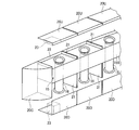
- disassembled the fairing cover is shown by FIG. It is a perspective view drawn in the state where the riser guide and guide tube in a fairing cover were seen through. It is a perspective view in which the state where the fairing cover is disassembled is shown. It is a perspective view which shows the structure of the fairing cover of 2nd Embodiment.
- FIG. 1 is a side view of a floating-type production storage / loading facility (FPSO facility) which is a first embodiment of a floating facility according to the present invention.
- FPSO facility floating-type production storage / loading facility
- the FPSO facility 10 of the first embodiment has a ship shape and includes a processing facility 11 for processing hydrocarbons such as crude oil and gas. After construction, the FPSO facility 10 is self-propelled or towed, transferred to the installation sea area (water area), and moored in the sea area (water area).
- a large number of flexible riser tubes 12 (only two are shown in FIG. 1) are attached to the FPSO facility 10 moored in the installation sea area, and hydrocarbons such as crude oil and gas are treated from the sea floor to the treatment facility 11. It is pumped up and processed.
- the hydrocarbons processed in the processing facility 11 are stored, for example, in a tank (not shown) provided in the hull.
- the riser pipe 12 is led from the processing equipment 11 along the ship side skin 13 to the seabed.
- a pair of riser guides 14 and 15 for fixing the position of each riser pipe 12 is provided on the ship side.
- the riser guide 14 is disposed along the hull longitudinal direction above the ship side outer plate 13 and fixes a portion of each riser pipe 12 close to the processing equipment 11 to the hull.
- the riser guide 15 is disposed along the bilge near the bilge below the draft L, and fixes the riser pipe 12 hanging down into the sea to the hull.
- FIG. 2A is a view of the riser guide 15 as viewed from the stern direction of FIG. 1 along the longitudinal direction of the hull, for example.
- FIG. 2B is an enlarged view of the stern side end of the riser guide 15 of FIG. It is a side view.
- FIG. 2C is a plan view of FIG. 2B viewed from above.
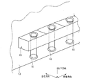
- FIG. 3 is a perspective view of FIGS. 2B and 2C as viewed obliquely from above the stern side.
- the main body of the riser guide 15 is a structure having a long box shape in the longitudinal direction of the hull, and protrudes outward from the ship side skin 13 near the bilge.
- guide tubes 16 for guiding each riser tube 12 along the vertical direction are arranged along the longitudinal direction at a predetermined interval, for example.
- the guide pipe 16 is a pipe that penetrates the main body of the riser guide 15 in the vertical direction. The diameter has been expanded.
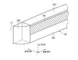
- FIG. 4 to 6 are perspective views showing the configuration of the fairing cover 20 of the first embodiment, and portions corresponding to those in FIG. 3 are drawn.
- FIG. 4 shows the appearance of the state in which the fairing cover 20 is attached to the riser guide 15, and
- FIG. 5 is a view in which the riser guide 15 in the fairing cover 20 is seen through. Moreover, the state which decomposed
- the front and rear portions (the bow side and the stern side) of the riser guide 15 are step-shaped in the front and rear portions because the shape of the riser guide 15 is a box, which causes an increase in resistance. Therefore, the front / rear cover member 20 ⁇ / b> C having an oblique member for alleviating the increase in resistance is provided integrally with the hull and the riser guide 15.
- An upper cover member 20U and a lower cover member 20D are attached to the upper and lower portions of the riser guide 15 so as to cover the guide tubes 16 projecting upward and downward from the main body of the riser guide 15, respectively.
- the upper cover member 20U and the lower cover member 20D are cover members that are removed after the FPSO facility 10 is transferred and installed, and are, for example, panel members each having an L-shaped cross section. That is, after the FPSO facility 10 is installed, the upper cover member 20U and the lower cover member 20D are removed as shown in FIG. In addition, between the upper cover member 20U and the lower cover member 20D that are attached to the riser guide 15, the side surface 15S of the riser guide 15 main body communicates to form one plane parallel to the ship-side outer plate 13.
- the top surface of the upper cover member 20U covers the upper opening of the guide tube 16, forms a flat surface that is the same height as the top surface of the front and rear cover member 20C, and the bottom surface of the lower cover member 20D
- the lower opening 16 is covered and a flat surface having the same height as the bottom surface of the front and rear cover member 20C is formed.
- the same number of the upper cover member 20U and the lower cover member 20D are provided corresponding to each guide tube 16.
- a plate-like frame plate 21 corresponding to the cross-sectional shape of the fairing cover 20 is provided between the guide tubes 16 perpendicular to the ship side outer plate at the approximate center, and the upper cover member 20U and the lower cover are provided.
- the member 20D can be fixed to the frame plate 21 using a predetermined attachment method.
- an attachment member 22 for attaching the upper cover member 20 ⁇ / b> U along the outer plate is provided at an edge along the ship-side outer plate 13.
- a similar attachment member 22 is also provided at a portion where the lower cover member 20D is in contact with the ship side outer plate (not shown).
- the upper cover member 20U and the lower cover member 20D are attached to the riser guide 15 or the ship side skin 13 by, for example, lashing with bolts, ropes or wire wires, or local welding. After installing the FPSO facility 10, an underwater worker Removed.
- the panel which comprises the upper cover member 20U and the lower cover member 20D is comprised, for example with a steel board etc., the removal operation
- the buoyancy body 23 is provided at a position corresponding to a void in the fairing cover 20 when the upper cover member 20U and the lower cover member 20D are attached to the riser guide 15. That is, it arrange
- the upper cover member 20U and the lower cover member 20D are described as steel panel members. However, both members or one of them is not a panel member but a steel plate or the like.
- the underwater weight is lighter than that of the panel member, and the canvas (membrane member) may have a good workability.
- the canvas fabric is attached to the attachment member 22 and the shape as a fairing cover is a frame plate. 21 is held.
- the fairing cover when the FPSO facility is transferred, the riser guide and the guide tube are covered by the fairing cover, so that the fluid resistance is lowered and the transfer efficiency is improved. Further, after the transfer and after the installation of the FPSO facility 10, the fairing cover can be easily removed by an underwater worker. Further, since the front and rear cover members are fixed, the number of cover members to be removed after installation is reduced, and the working time is shortened.
- FIG. 7 is a perspective view corresponding to FIG. 4 of the first embodiment.
- the fairing cover 25 and the riser guide 15 are integrally configured.
- the external appearance of the fairing cover 25 of the second embodiment is substantially the same as the external appearance of FIG. 4, but the top surface 25T and the bottom surface 25B have openings 16A through which the riser pipes penetrate in correspondence with the guide pipes 16, respectively. 16B is provided.
- a lid-like cover member is fitted in each of the openings 16A and 16B. After the FPSO facility 10 is installed, only these lid-like cover members are removed, but a slight increase in resistance is allowed. Thus, it is possible to eliminate the lid-like cover member.
- the same effects as those of the first embodiment can be obtained in the configuration of the second embodiment.
- the lid-like cover member needs to be removed, so that the work amount of the underwater worker is further reduced.
- the riser guide of the floating production storage and loading (FPSO) facility has been described as an example.
- the present invention provides a projecting structure for anchoring the mooring line to the hull, such as a chain fair leader.
- FPSO floating body storage and shipping
Landscapes
- Physics & Mathematics (AREA)
- Fluid Mechanics (AREA)
- Engineering & Computer Science (AREA)
- Chemical & Material Sciences (AREA)
- Combustion & Propulsion (AREA)
- Mechanical Engineering (AREA)
- Ocean & Marine Engineering (AREA)
- Architecture (AREA)
- Civil Engineering (AREA)
- Structural Engineering (AREA)
- Earth Drilling (AREA)
- Details Of Aerials (AREA)
Abstract
Description
図1は、本発明に係る浮体設備の第1実施形態である浮体式生産貯蔵積出設備(FPSO設備)の側面図である。
11 処理設備
12 ライザー管
13 船側外板
15 ライザーガイド(喫水L下)
15S ライザーガイド側壁
16 ガイド管
16A、16B 開口
20、25 フェアリングカバー
20C 前後カバー部材
20D 下部カバー部材
20U 上部カバー部材
21 フレーム板
22 取付部材
23 浮力体(ボイド)
L 喫水
Claims (7)
- 船体形状を呈する浮体設備の喫水下に、ライザーまたは係留索を船体に引きとめるために設けられる突出構造物を覆い、前記突出構造物による推進方向の流体抵抗を低減することを特徴とするフェアリングカバー。
- 前記突出構造物から取り外し可能なカバー部材を備えることを特徴とする請求項1に記載のフェアリングカバー。
- 前記取り外し可能なカバー部材が浮力体を備えることを特徴とする請求項2に記載のフェアリングカバー。
- 前記突出構造物の前方部と後方部とを覆うカバー部材が前記突出構造物に恒久的に取り付けられ、前記前方部と後方部を覆うカバー部材を除く、前記突出構造物の中央部を覆うカバー部材が前記取り外し可能なカバー部材から構成されることを特徴とする請求項2または請求項3の何れか一項に記載のフェアリングカバー。
- 前記取り外し可能なカバー部材が膜構造、またはパネル構造で構成されることを特徴とする請求項2~4の何れか一項に記載のフェアリングカバー。
- カバー部材の全てが、前記突出構造物に一体的に構成され、前記フェアリングカバーの頂面と底面は、各ガイド管に対応させてライザー管が貫通する開口を備えることを特徴とする請求項1に記載のフェアリングカバー。
- 請求項1~請求項6に記載のフェアリングカバーを備えることを特徴とする浮体設備。
Priority Applications (3)
| Application Number | Priority Date | Filing Date | Title |
|---|---|---|---|
| KR1020177016859A KR20170102869A (ko) | 2014-12-19 | 2015-11-19 | 페어링 커버 |
| CN201580067503.3A CN107207074A (zh) | 2014-12-19 | 2015-11-19 | 整流罩 |
| SG11201704996WA SG11201704996WA (en) | 2014-12-19 | 2015-11-19 | Fairing cover |
Applications Claiming Priority (2)
| Application Number | Priority Date | Filing Date | Title |
|---|---|---|---|
| JP2014-257466 | 2014-12-19 | ||
| JP2014257466A JP2016117363A (ja) | 2014-12-19 | 2014-12-19 | フェアリングカバー |
Publications (1)
| Publication Number | Publication Date |
|---|---|
| WO2016098520A1 true WO2016098520A1 (ja) | 2016-06-23 |
Family
ID=56126418
Family Applications (1)
| Application Number | Title | Priority Date | Filing Date |
|---|---|---|---|
| PCT/JP2015/082496 Ceased WO2016098520A1 (ja) | 2014-12-19 | 2015-11-19 | フェアリングカバー |
Country Status (5)
| Country | Link |
|---|---|
| JP (1) | JP2016117363A (ja) |
| KR (1) | KR20170102869A (ja) |
| CN (1) | CN107207074A (ja) |
| SG (1) | SG11201704996WA (ja) |
| WO (1) | WO2016098520A1 (ja) |
Families Citing this family (1)
| Publication number | Priority date | Publication date | Assignee | Title |
|---|---|---|---|---|
| WO2019044194A1 (ja) * | 2017-08-31 | 2019-03-07 | 三井E&S造船株式会社 | ライザー管支持構造 |
Citations (8)
| Publication number | Priority date | Publication date | Assignee | Title |
|---|---|---|---|---|
| JPS50125988U (ja) * | 1974-03-30 | 1975-10-16 | ||
| US4459066A (en) * | 1981-02-05 | 1984-07-10 | Shell Oil Company | Flexible line system for a floating body |
| JPS59186200U (ja) * | 1983-05-30 | 1984-12-11 | 川崎重工業株式会社 | 海洋移動構造物の推進機着脱装置 |
| JPS61159292U (ja) * | 1985-03-26 | 1986-10-02 | ||
| JPH0840347A (ja) * | 1994-07-26 | 1996-02-13 | Kawasaki Heavy Ind Ltd | 没水体装備船舶の連結体先端部構造 |
| JP2002079991A (ja) * | 2000-09-06 | 2002-03-19 | Hitachi Zosen Corp | 浮体構造 |
| US20040218981A1 (en) * | 2001-02-19 | 2004-11-04 | Laurent Chenin | Seafloor-surface connecting installation of a submarine pipeline installed at great depth |
| JP2006519137A (ja) * | 2003-02-28 | 2006-08-24 | モデク・インターナショナル・エルエルシー | ライザー・パイプの支持システムおよび支持方法 |
Family Cites Families (4)
| Publication number | Priority date | Publication date | Assignee | Title |
|---|---|---|---|---|
| US3209718A (en) * | 1964-06-05 | 1965-10-05 | Commercial Engineering Corp | Detachable fairing assembly |
| JPS61159292A (ja) * | 1985-01-07 | 1986-07-18 | Mitsubishi Electric Corp | 亜鉛メツキ鋼板のレ−ザ溶接方法 |
| NO335480B1 (no) * | 2013-04-16 | 2014-12-15 | Gva Consultants Ab | Rørledningsoppheng |
| CN203921160U (zh) * | 2014-04-29 | 2014-11-05 | 中国舰船研究设计中心 | 适用于中高速艇的可拆式声纳导流罩 |
-
2014
- 2014-12-19 JP JP2014257466A patent/JP2016117363A/ja active Pending
-
2015
- 2015-11-19 CN CN201580067503.3A patent/CN107207074A/zh active Pending
- 2015-11-19 WO PCT/JP2015/082496 patent/WO2016098520A1/ja not_active Ceased
- 2015-11-19 KR KR1020177016859A patent/KR20170102869A/ko not_active Withdrawn
- 2015-11-19 SG SG11201704996WA patent/SG11201704996WA/en unknown
Patent Citations (8)
| Publication number | Priority date | Publication date | Assignee | Title |
|---|---|---|---|---|
| JPS50125988U (ja) * | 1974-03-30 | 1975-10-16 | ||
| US4459066A (en) * | 1981-02-05 | 1984-07-10 | Shell Oil Company | Flexible line system for a floating body |
| JPS59186200U (ja) * | 1983-05-30 | 1984-12-11 | 川崎重工業株式会社 | 海洋移動構造物の推進機着脱装置 |
| JPS61159292U (ja) * | 1985-03-26 | 1986-10-02 | ||
| JPH0840347A (ja) * | 1994-07-26 | 1996-02-13 | Kawasaki Heavy Ind Ltd | 没水体装備船舶の連結体先端部構造 |
| JP2002079991A (ja) * | 2000-09-06 | 2002-03-19 | Hitachi Zosen Corp | 浮体構造 |
| US20040218981A1 (en) * | 2001-02-19 | 2004-11-04 | Laurent Chenin | Seafloor-surface connecting installation of a submarine pipeline installed at great depth |
| JP2006519137A (ja) * | 2003-02-28 | 2006-08-24 | モデク・インターナショナル・エルエルシー | ライザー・パイプの支持システムおよび支持方法 |
Also Published As
| Publication number | Publication date |
|---|---|
| JP2016117363A (ja) | 2016-06-30 |
| SG11201704996WA (en) | 2017-07-28 |
| KR20170102869A (ko) | 2017-09-12 |
| CN107207074A (zh) | 2017-09-26 |
Similar Documents
| Publication | Publication Date | Title |
|---|---|---|
| CN101384475B (zh) | 深水安装船只 | |
| JP2020033009A (ja) | 浮体式炭化水素貯蔵プラントおよび/または浮体式炭化水素処理プラントの外殻として用いる船体、同船体を製造するための方法、同船体を備える船舶、ならびに同船体を有する同船舶を製造するための方法 | |
| EP3261922B1 (en) | Water intake system and floating vessel equipped with such a system | |
| JP2006525189A (ja) | 船舶係泊方法及びシステム | |
| CN110869274A (zh) | 用于生产和储存碳氢化合物产品的近海船舶 | |
| US20130299179A1 (en) | Riser configuration | |
| US6503022B1 (en) | Bouyant moon pool plug | |
| KR20140035588A (ko) | 불연속 선저부를 가지는 부양식 선체 및 그 조립방법 | |
| KR20150137353A (ko) | 반잠수식 해양구조물의 추가 부력탱크 탈착구조 | |
| RU2571681C2 (ru) | Наливной рукав | |
| WO2016098520A1 (ja) | フェアリングカバー | |
| CN1261311A (zh) | 双点系泊系统 | |
| KR20220137987A (ko) | 라이저 문풀을 포함하는 스프레드 계류 선박 | |
| JP2014117980A (ja) | 浮標の設置方法 | |
| CN101351379B (zh) | 供应船辅助钻井装置与浮动生产设备的捆绑 | |
| JP7088452B2 (ja) | 洋上浮体構造物 | |
| KR102701430B1 (ko) | 선박의 데크하우스 및 이를 포함하는 선박 | |
| KR101735330B1 (ko) | 해양 구조물의 페어리드 씨패스트닝 장치 | |
| US9944358B2 (en) | Transportation and installation of subsea rigid tie-in connections | |
| KR20160003562U (ko) | 라이저 보호용 부유식 완충장치 | |
| JP6973732B2 (ja) | ライザー管支持構造 | |
| GB2351724A (en) | Offshore oil loading | |
| KR101526365B1 (ko) | 선박 및 선박의 배치 방법 | |
| KR20210034199A (ko) | 일점계류 셔틀탱커 | |
| KR101588719B1 (ko) | 선박 |
Legal Events
| Date | Code | Title | Description |
|---|---|---|---|
| 121 | Ep: the epo has been informed by wipo that ep was designated in this application |
Ref document number: 15869728 Country of ref document: EP Kind code of ref document: A1 |
|
| WWE | Wipo information: entry into national phase |
Ref document number: 11201704996W Country of ref document: SG |
|
| ENP | Entry into the national phase |
Ref document number: 20177016859 Country of ref document: KR Kind code of ref document: A |
|
| NENP | Non-entry into the national phase |
Ref country code: DE |
|
| 122 | Ep: pct application non-entry in european phase |
Ref document number: 15869728 Country of ref document: EP Kind code of ref document: A1 |