WO2016088359A1 - Opening/closing detection device for vehicle opening/closing member - Google Patents
Opening/closing detection device for vehicle opening/closing member Download PDFInfo
- Publication number
- WO2016088359A1 WO2016088359A1 PCT/JP2015/005958 JP2015005958W WO2016088359A1 WO 2016088359 A1 WO2016088359 A1 WO 2016088359A1 JP 2015005958 W JP2015005958 W JP 2015005958W WO 2016088359 A1 WO2016088359 A1 WO 2016088359A1
- Authority
- WO
- WIPO (PCT)
- Prior art keywords
- opening
- user
- vehicle
- closing
- mark
- Prior art date
Links
Images


Classifications
-
- E—FIXED CONSTRUCTIONS
- E05—LOCKS; KEYS; WINDOW OR DOOR FITTINGS; SAFES
- E05F—DEVICES FOR MOVING WINGS INTO OPEN OR CLOSED POSITION; CHECKS FOR WINGS; WING FITTINGS NOT OTHERWISE PROVIDED FOR, CONCERNED WITH THE FUNCTIONING OF THE WING
- E05F15/00—Power-operated mechanisms for wings
- E05F15/70—Power-operated mechanisms for wings with automatic actuation
- E05F15/73—Power-operated mechanisms for wings with automatic actuation responsive to movement or presence of persons or objects
-
- B—PERFORMING OPERATIONS; TRANSPORTING
- B60—VEHICLES IN GENERAL
- B60J—WINDOWS, WINDSCREENS, NON-FIXED ROOFS, DOORS, OR SIMILAR DEVICES FOR VEHICLES; REMOVABLE EXTERNAL PROTECTIVE COVERINGS SPECIALLY ADAPTED FOR VEHICLES
- B60J5/00—Doors
-
- B—PERFORMING OPERATIONS; TRANSPORTING
- B60—VEHICLES IN GENERAL
- B60J—WINDOWS, WINDSCREENS, NON-FIXED ROOFS, DOORS, OR SIMILAR DEVICES FOR VEHICLES; REMOVABLE EXTERNAL PROTECTIVE COVERINGS SPECIALLY ADAPTED FOR VEHICLES
- B60J5/00—Doors
- B60J5/10—Doors arranged at the vehicle rear
-
- B—PERFORMING OPERATIONS; TRANSPORTING
- B60—VEHICLES IN GENERAL
- B60R—VEHICLES, VEHICLE FITTINGS, OR VEHICLE PARTS, NOT OTHERWISE PROVIDED FOR
- B60R13/00—Elements for body-finishing, identifying, or decorating; Arrangements or adaptations for advertising purposes
-
- B—PERFORMING OPERATIONS; TRANSPORTING
- B60—VEHICLES IN GENERAL
- B60R—VEHICLES, VEHICLE FITTINGS, OR VEHICLE PARTS, NOT OTHERWISE PROVIDED FOR
- B60R13/00—Elements for body-finishing, identifying, or decorating; Arrangements or adaptations for advertising purposes
- B60R13/005—Manufacturers' emblems, name plates, bonnet ornaments, mascots or the like; Mounting means therefor
-
- B—PERFORMING OPERATIONS; TRANSPORTING
- B60—VEHICLES IN GENERAL
- B60R—VEHICLES, VEHICLE FITTINGS, OR VEHICLE PARTS, NOT OTHERWISE PROVIDED FOR
- B60R16/00—Electric or fluid circuits specially adapted for vehicles and not otherwise provided for; Arrangement of elements of electric or fluid circuits specially adapted for vehicles and not otherwise provided for
- B60R16/02—Electric or fluid circuits specially adapted for vehicles and not otherwise provided for; Arrangement of elements of electric or fluid circuits specially adapted for vehicles and not otherwise provided for electric constitutive elements
-
- E—FIXED CONSTRUCTIONS
- E05—LOCKS; KEYS; WINDOW OR DOOR FITTINGS; SAFES
- E05B—LOCKS; ACCESSORIES THEREFOR; HANDCUFFS
- E05B49/00—Electric permutation locks; Circuits therefor ; Mechanical aspects of electronic locks; Mechanical keys therefor
-
- E—FIXED CONSTRUCTIONS
- E05—LOCKS; KEYS; WINDOW OR DOOR FITTINGS; SAFES
- E05B—LOCKS; ACCESSORIES THEREFOR; HANDCUFFS
- E05B81/00—Power-actuated vehicle locks
- E05B81/54—Electrical circuits
- E05B81/64—Monitoring or sensing, e.g. by using switches or sensors
-
- E—FIXED CONSTRUCTIONS
- E05—LOCKS; KEYS; WINDOW OR DOOR FITTINGS; SAFES
- E05B—LOCKS; ACCESSORIES THEREFOR; HANDCUFFS
- E05B81/00—Power-actuated vehicle locks
- E05B81/54—Electrical circuits
- E05B81/64—Monitoring or sensing, e.g. by using switches or sensors
- E05B81/76—Detection of handle operation; Detection of a user approaching a handle; Electrical switching actions performed by door handles
- E05B81/78—Detection of handle operation; Detection of a user approaching a handle; Electrical switching actions performed by door handles as part of a hands-free locking or unlocking operation
-
- E—FIXED CONSTRUCTIONS
- E05—LOCKS; KEYS; WINDOW OR DOOR FITTINGS; SAFES
- E05B—LOCKS; ACCESSORIES THEREFOR; HANDCUFFS
- E05B83/00—Vehicle locks specially adapted for particular types of wing or vehicle
- E05B83/16—Locks for luggage compartments, car boot lids or car bonnets
- E05B83/18—Locks for luggage compartments, car boot lids or car bonnets for car boot lids or rear luggage compartments
-
- E—FIXED CONSTRUCTIONS
- E05—LOCKS; KEYS; WINDOW OR DOOR FITTINGS; SAFES
- E05F—DEVICES FOR MOVING WINGS INTO OPEN OR CLOSED POSITION; CHECKS FOR WINGS; WING FITTINGS NOT OTHERWISE PROVIDED FOR, CONCERNED WITH THE FUNCTIONING OF THE WING
- E05F15/00—Power-operated mechanisms for wings
- E05F15/70—Power-operated mechanisms for wings with automatic actuation
- E05F15/73—Power-operated mechanisms for wings with automatic actuation responsive to movement or presence of persons or objects
- E05F2015/765—Power-operated mechanisms for wings with automatic actuation responsive to movement or presence of persons or objects using optical sensors
-
- E—FIXED CONSTRUCTIONS
- E05—LOCKS; KEYS; WINDOW OR DOOR FITTINGS; SAFES
- E05Y—INDEXING SCHEME RELATING TO HINGES OR OTHER SUSPENSION DEVICES FOR DOORS, WINDOWS OR WINGS AND DEVICES FOR MOVING WINGS INTO OPEN OR CLOSED POSITION, CHECKS FOR WINGS AND WING FITTINGS NOT OTHERWISE PROVIDED FOR, CONCERNED WITH THE FUNCTIONING OF THE WING
- E05Y2201/00—Constructional elements; Accessories therefore
- E05Y2201/60—Suspension or transmission members; Accessories therefore
- E05Y2201/622—Suspension or transmission members elements
- E05Y2201/676—Transmission of human force
- E05Y2201/68—Handles, cranks
-
- E—FIXED CONSTRUCTIONS
- E05—LOCKS; KEYS; WINDOW OR DOOR FITTINGS; SAFES
- E05Y—INDEXING SCHEME RELATING TO HINGES OR OTHER SUSPENSION DEVICES FOR DOORS, WINDOWS OR WINGS AND DEVICES FOR MOVING WINGS INTO OPEN OR CLOSED POSITION, CHECKS FOR WINGS AND WING FITTINGS NOT OTHERWISE PROVIDED FOR, CONCERNED WITH THE FUNCTIONING OF THE WING
- E05Y2400/00—Electronic control; Power supply; Power or signal transmission; User interfaces
- E05Y2400/80—User interfaces
- E05Y2400/85—User input means
- E05Y2400/852—Sensors
- E05Y2400/856—Actuation thereof
- E05Y2400/858—Actuation thereof by body parts
- E05Y2400/86—Actuation thereof by body parts by hand
-
- E—FIXED CONSTRUCTIONS
- E05—LOCKS; KEYS; WINDOW OR DOOR FITTINGS; SAFES
- E05Y—INDEXING SCHEME RELATING TO HINGES OR OTHER SUSPENSION DEVICES FOR DOORS, WINDOWS OR WINGS AND DEVICES FOR MOVING WINGS INTO OPEN OR CLOSED POSITION, CHECKS FOR WINGS AND WING FITTINGS NOT OTHERWISE PROVIDED FOR, CONCERNED WITH THE FUNCTIONING OF THE WING
- E05Y2600/00—Mounting or coupling arrangements for elements provided for in this subclass
- E05Y2600/40—Mounting location; Visibility of the elements
- E05Y2600/46—Mounting location; Visibility of the elements in or on the wing
-
- E—FIXED CONSTRUCTIONS
- E05—LOCKS; KEYS; WINDOW OR DOOR FITTINGS; SAFES
- E05Y—INDEXING SCHEME RELATING TO HINGES OR OTHER SUSPENSION DEVICES FOR DOORS, WINDOWS OR WINGS AND DEVICES FOR MOVING WINGS INTO OPEN OR CLOSED POSITION, CHECKS FOR WINGS AND WING FITTINGS NOT OTHERWISE PROVIDED FOR, CONCERNED WITH THE FUNCTIONING OF THE WING
- E05Y2900/00—Application of doors, windows, wings or fittings thereof
- E05Y2900/50—Application of doors, windows, wings or fittings thereof for vehicles
- E05Y2900/53—Application of doors, windows, wings or fittings thereof for vehicles characterised by the type of wing
- E05Y2900/531—Doors
-
- E—FIXED CONSTRUCTIONS
- E05—LOCKS; KEYS; WINDOW OR DOOR FITTINGS; SAFES
- E05Y—INDEXING SCHEME RELATING TO HINGES OR OTHER SUSPENSION DEVICES FOR DOORS, WINDOWS OR WINGS AND DEVICES FOR MOVING WINGS INTO OPEN OR CLOSED POSITION, CHECKS FOR WINGS AND WING FITTINGS NOT OTHERWISE PROVIDED FOR, CONCERNED WITH THE FUNCTIONING OF THE WING
- E05Y2900/00—Application of doors, windows, wings or fittings thereof
- E05Y2900/50—Application of doors, windows, wings or fittings thereof for vehicles
- E05Y2900/53—Application of doors, windows, wings or fittings thereof for vehicles characterised by the type of wing
- E05Y2900/546—Tailgates
Definitions
- the present invention relates to an opening / closing detection device for a vehicle opening / closing body, and in particular, based on signals from a plurality of sensors arranged along a predetermined portion of a mark attached to the vehicle, the opening / closing for the vehicle of the user.
- the present invention relates to a technique for determining the intention to open and close the body.
- Patent Document 1 provides a non-contact switch for an automatic door that can easily change the object detection direction in order to prevent detection by a passerby or the like that crosses away from the automatic door. According to the present invention, it is possible to easily set an appropriate object detection direction according to the installation location and application, and even if the object detection direction is almost directly below, the position where the hand should be held is known. Because it is easy, reliable detection is possible.
- Patent Document 1 The technology of Patent Document 1 is basically applied to an automatic door for a building.
- the effect of an erroneous opening / closing operation of a vehicle opening / closing body due to an erroneous detection of an operation sensor for a vehicle door is more than the effect of an erroneous opening / closing operation of the automatic door for a building due to an erroneous detection of an operation sensor for a building automatic door.
- an object of the present invention is to propose an opening / closing detection device for a vehicle opening / closing body that reduces an erroneous opening / closing operation of the vehicle opening / closing body due to erroneous detection of an operation sensor of the vehicle opening / closing body.
- One embodiment of the present invention includes a plurality of sensors configured to be arranged along a predetermined portion of a mark attached to a vehicle, and an order of an operation of tracing a predetermined portion of the mark by a user of the vehicle.
- an open / close detection device including a control unit that outputs an operation trigger signal that instructs an open / close operation of an opening / closing body of a vehicle when a detection signal in a tracing order of a predetermined part is input from a plurality of sensors that detect .
- An open / close detection device receives detection signals of a tracing order of a predetermined part of a mark from a plurality of sensors that detect the order of the tracing operation of the predetermined part of the mark by a user of the vehicle. Then, an operation trigger signal for instructing the opening / closing operation of the vehicle opening / closing body is output. Therefore, even if a plurality of sensors mistakenly detect a vehicle, a structure, a person, or the like that has passed nearby, it is rare that it is detected in the tracing order. The possibility of accidental opening and closing operations is reduced.
- FIG. 1 is a schematic configuration diagram of a vehicle 1 including an open / close detection device 10 according to the first embodiment of the present invention.
- the vehicle 1 includes an opening / closing body 2, a mark 3, an opening / closing body ECU (Electronic Control Unit) 4, an opening / closing body driving device 5, and an opening / closing detection device 10.
- ECU Electronic Control Unit
- the opening / closing body 2 is a back door, a power slide door, or the like of the vehicle 1, and is opened / closed by the opening / closing body driving device 5.
- the opening / closing body driving device 5 is controlled by the opening / closing body ECU 4.
- the opening / closing body 2 may be a front door, a trunk lid, a door mirror, a bonnet, a sunroof, a fuel filler door, or the like that is opened and closed by electric power (opening or closing).
- the back door may be a power back door or a back door provided with a torsion spring or a gas damper.
- the mark 3 is attached to the surface of the opening / closing body 2 so as to be visible to the user.
- the mark 3 is a character, a figure, a symbol, a three-dimensional shape, a combination thereof, or a combination of these and a color.
- the mark 3 is an emblem indicating the brand or vehicle type or vehicle grade of the vehicle 1 attached to the back door as shown in FIG.
- the mark 3 is not limited to the configuration attached to the opening / closing body 2 to be actuated, and may be attached to any part of the vehicle 1 such as a center pillar. In consideration of the convenience of the user, the mark 3 may be attached in the vicinity of the opening / closing body 2 so that the user's hand can easily reach.
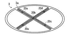
- FIG. 2 is a schematic diagram showing an example of the mark 3 in which a plurality of sensors 20 are arranged.
- a mark 3 shown in FIG. 2 is an emblem of the vehicle 1 formed by a combination of an ellipse and an X-shaped three-dimensional shape.
- a plurality of sensors 20 (sensors 20a to 20e) are arranged along a predetermined portion 3a (shaded portion in FIG. 2).
- the predetermined part 3a is an X-shaped three-dimensional part.
- the plurality of sensors 20 are non-contact or contact sensors that output a detection signal to the control unit 30 when a user's body (hand, finger, foot, etc.) is detected.
- a non-contact type sensor is a capacitance sensor that detects a user's body from a change in capacitance caused by the user's body that has entered the detection range
- a contact type sensor is a sensor that detects the pressure applied to the sensor.
- a pressure sensor, a membrane sensor, or the like that detects the user's body based on a change.
- an infrared sensor, an ultrasonic sensor, a photoelectric sensor, a laser sensor, a camera, or the like may be used.
- the detection signal may be a signal having a 1-bit value.
- the plurality of sensors 20 output a value of “1” to the control unit 30 when detecting the user's body.
- the plurality of sensors 20 can detect the movement of the user's body at the predetermined portion 3a from the position of each sensor 20a to 20e and the timing at which each of the sensors 20a to 20e detects the user's body. For example, the plurality of sensors 20 can detect the order of movement of the user's body between the sensors 20a to 20e.
- FIG. 3 is a block diagram of the open / close detection device 10 and the open / close body ECU 4 and the like.
- the open / close detection device 10 includes a plurality of sensors 20 and a control unit 30.
- the control unit 30 is a computer that includes an input interface (I / F) 31, a RAM (Random Access Memory) 32, a ROM (Read Only Memory) 33, a CPU (Central Processing Unit) 34, and an output I / F 35.
- the function of the control unit 30 to be described later may be realized by software processing using the above-described configurations 31 to 35, or may be realized by hardware processing using a logic circuit although detailed description is omitted. May be.
- the input I / F 31 receives detection signals from the plurality of sensors 20 and converts them into data that can be processed by the CPU 34, and the data is temporarily stored in the RAM 32.
- the CPU 34 processes the data based on a predetermined program stored in advance in the ROM 33, and outputs the processing result to the opening / closing body ECU 4 via the output I / F 35.
- the control unit 30 determines the user's intention to open / close the opening / closing body 2 based on the detection signals from the plurality of sensors 20, and instructs the opening / closing body ECU 4 to open or close the opening / closing body 2.
- the activation trigger signal may be a signal having a 1-bit value or a signal having a plurality of bits.
- the communication between the plurality of sensors 20 and the control unit 30 may be serial communication or parallel communication.
- the opening / closing body ECU 4 When the opening / closing body ECU 4 receives an operation trigger signal from the opening / closing detection device 10, the opening / closing body ECU 4 changes the polarity of the voltage applied to the motor 5 a of the opening / closing body driving device 5 according to the opening / closing state of the opening / closing body 2. And the direction of rotation (forward or reverse) is controlled. For example, when the opening / closing body ECU 4 determines that the opening / closing body 2 has already been closed, the opening operation of the opening / closing body 2 is required, so the motor 5a is rotated forward. When the opening / closing body ECU 4 determines that the opening / closing body 2 is already open, the opening / closing body 2 is requested to close, so the motor 5a is reversed.
- the forward rotation of the motor 5 a corresponds to the opening operation of the opening / closing body 2
- the reverse rotation of the motor 5 a corresponds to the closing operation of the opening / closing body 2.
- the opening / closing body ECU 4 may store the opening / closing state of the opening / closing body 2 at the time of the previous opening / closing operation of the opening / closing body 2, and use it for determining the opening / closing state of the opening / closing body 2.
- the rotation of the motor 5a is transmitted to the opening / closing body 2 via the drive mechanism 5b, and opens / closes the opening / closing body 2.
- the opening / closing body 2 is a back door provided with a torsion spring or a gas damper
- the opening / closing body ECU 4 inputs an operation trigger signal related to the user's opening intention from the opening / closing detection device 10
- the opening / closing body ECU 4 locks the back door. Configured to release.
- the back door is opened by the force of the torsion spring and the gas damper.
- means for determining the open / close state of the open / close body 2 may be provided in the open / close detection device 10 so that the open / close detection device 10 outputs an operation trigger signal to the open / close body ECU 4 together with information on the open / close direction of the open / close body 2.
- FIG. 4A, 4B, and 5 a method for determining the user's intention to open / close by the open / close detection device 10 will be described with reference to FIGS. 4A, 4B, and 5.
- FIG. 4A, 4B, and 5 a method for determining the user's intention to open / close by the open / close detection device 10 will be described with reference to FIGS. 4A, 4B, and 5.
- FIG. 4 In order to simplify the description, the opening operation of the opening / closing body 2 based on the user's intention to open will be described below, but the present invention is not limited to this.
- the user can convey the user's intention to open the opening / closing body 2 to the opening / closing detection device 10 by performing an action of tracing the predetermined part 3a of the mark 3 with the body (finger, hand, etc.). .
- each of the sensors 20a to 20e of the plurality of sensors 20 of the open / close detection device 10 detects the user's body in the order of the user's action of tracing the predetermined part 3a of the mark 3 (referred to as "tracing order").
- detection signals are input to the control unit 30 from the sensors 20a to 20e of the plurality of sensors 20 in the tracing order of the predetermined part 3a.
- tracing includes the meaning of moving along the predetermined portion 3a while the user's body is in contact with the predetermined portion 3a of the mark 3 (in a contact state). Furthermore, “tracing” (or “tracing”) also includes the meaning of moving the user's body along the predetermined portion 3a in a state of being lifted from the predetermined portion 3a (in a non-contact state).
- a contact-type sensor is used as the plurality of sensors 20
- the user needs to bring the body into contact with the predetermined part 3a.
- a non-contact sensor the user determines the body in advance. There is no need to contact the part 3a.
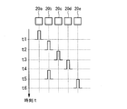
- the control unit 30 inputs a detection signal from the sensor 20a at time t1, and inputs a detection signal from the sensor 20b at time t2.
- control unit 30 inputs a detection signal from the sensor 20c at time t3, inputs a detection signal from the sensor 20d at time t4, inputs a detection signal from the sensor 20b at time t5, and from the sensor 20e at time t6. Input the detection signal.
- the tracing order may be configured so as to be appropriately set according to the user's preference.
- FIG. 5 is a flowchart relating to a determination process of the user's intention to open, which is executed by the CPU 34 of the control unit 30 based on a program stored in the ROM 33 in advance. 5 may be started when the open / close detection device 10 is supplied with power from the battery of the vehicle 1, and may be repeated, for example, in a cycle on the order of milliseconds. Further, the power supplied to the control unit 30 is reduced until the sensor 20a corresponding to the first in the tracing order detects the user's body, and the determination process starts in earnest by increasing the power supply after the detection. Doing so will result in a reduction in power.
- step S1 the control unit 30 determines whether or not a detection signal is input from the sensor 20a corresponding to the first position in the tracing order of the predetermined part 3a of the mark 3.
- Step S2 the control unit 30 determines whether the detection signal is input from the sensor 20b corresponding to the next position in the tracing order. To do.
- step S3 the control unit 30 determines whether or not a predetermined time has elapsed since the detection signal from the sensor 20a was input. .
- the predetermined time may be about 1 second or may be a value on the order of milliseconds to microseconds, and is set in consideration of user convenience and the like.
- the control unit 30 When it is determined that the predetermined time has elapsed (Yes in step S3), in step S9, the control unit 30 generates a warning sound, a warning light, or the like so as to notify the user that the opening operation has failed. Good. Note that step S9 may be omitted.
- step S4 determines that the sensor 20c corresponds to the next position in the tracing order. It is determined whether or not a detection signal is input from.
- step S5 the control unit 30 determines whether or not a predetermined time has elapsed since the detection signal from the sensor 20b was input. . The same is repeated for the sensors 20d and 20b.
- step S6 the control unit 30 determines whether a detection signal is input from the sensor 20e corresponding to the last position in the tracing order.
- step S7 the control unit 30 determines whether or not the predetermined time has elapsed since the detection signal from the sensor 20e was input. To do.
- Step S8 the control unit 30 determines the user's intention to open the opening / closing body 2 and outputs an operation trigger signal. Output to the opening / closing body ECU4.
- the control unit 30 generates a confirmation sound or the like to inform the user that the opening operation has been successful or to prompt the user to leave the opening / closing body 2. Good.
- control unit 30 of the open / close detection device 10 can determine the user's intention to open the open / close body 2 based on the detection signals indicating the tracing order from the plurality of sensors 20.
- the present invention is not limited to this, and the operation trigger signal may not be output if the total time from the first determination step to the last determination step exceeds a predetermined time.
- the control unit 30 may determine the user's intention to open as follows. As shown in Table 1, the control unit 30 of the open / close detection device 10 creates a table on the RAM 32 in the order in which detection signals from the plurality of sensors 20 are input, and creates the operation condition table stored in advance in the ROM 33 and the table. Compare with table. If the two coincide, it is determined that the user has an intention to open / close, and the control unit 30 may output an operation trigger signal to the opening / closing body ECU 4.
- control unit 30 determines that the user has an intention to open and operates. You may make it output a trigger signal to opening-closing body ECU4.
- the open / close detection device 10 includes the predetermined part of the mark 3 from the plurality of sensors 20 that detect the order of the movement of the predetermined part 3a of the mark 3 by the user of the vehicle 1.
- an operation trigger signal that instructs the opening / closing operation of the opening / closing body 2 of the vehicle 1 is output. For this reason, even if a plurality of sensors 20 erroneously detect a vehicle, structure, or person passing through the sensor 20, it is rare that the sensor 20 is erroneously detected in the tracing order. The possibility of being reduced is reduced.
- the user by increasing the number of the plurality of sensors 20, it is possible to further reduce the malfunction of the opening / closing body due to erroneous detection. In this case, it may seem difficult for the user to remember the order in which the plurality of sensors 20 are traced. However, since the user only has to perform the tracing operation along the mark 3, it is particularly necessary to change the order. It is not necessary to remember the tracing order, and the convenience for the user is improved. In addition, since the user only has to trace the predetermined part 3a of the mark 3 in order to open and close the opening / closing body 2, the user takes out and operates the wireless key or remembers a complicated operation for opening and closing. There is no need.
- the predetermined part 3a of the mark 3 represents a character or the like
- the writing order is set as the tracing order
- the predetermined portion 3a is a door outside handle or the like
- the user by setting the opening / closing operation direction of the opening / closing body 2 as a tracing order, the user performs the opening / closing operation of the opening / closing body 2 by a natural operation. be able to.
- the user does not need to touch the vehicle 1, so there is no need to worry about getting hands, fingers, etc. dirty.
- the plurality of sensors 20 are embedded along the predetermined portion 3a of the mark 3 (particularly the emblem), it is not necessary to separately provide a member for the plurality of sensors 20, and the plurality of sensors 20 are provided on the vehicle 1. Since it does not appear in the appearance, there is a favorable advantage in design.
- the open / close detection device 10 according to the second embodiment of the present invention will be described with reference to FIGS. 6A, 6B, 7 and 8.
- a distance measuring sensor 22 is arranged.
- the distance measurement sensor 22 measures the distance d from the distance measurement sensor 22, in other words, the opening / closing body 2 to which the mark 3 is attached, to the user's body, based on the reflection of infrared rays irradiated to the user's body. It is an infrared sensor that outputs information to the control unit 30.
- an ultrasonic sensor, a laser sensor, or the like may be used.
- the distance measuring sensor 22 is not limited to the configuration arranged in the mark 3, and is arranged at any position of the opening / closing body 2 or the vehicle 1 that can measure the distance from the opening / closing body 2 to the user's body. Also good. Although detailed description is omitted, the present invention is not limited to the configuration in which the distance measurement sensor 22 is provided. Instead of providing the distance measurement sensor 22, information such as clearance sonar already provided in the vehicle 1 for another use is used. Also good.
- an authentication ECU 40 is installed in the vehicle 1, and the authentication ECU 40 is connected to the control unit 30 of the open / close detection device 10.
- the authentication ECU 40 wirelessly communicates with the smart entry key that the user has, and determines that the user having the smart entry key is a valid user of the vehicle 1. Yes (authentication successful).
- authentication ECU40 transmits the authentication information which concerns on the said authentication establishment to the control part 30.
- the authentication unit 36 determines whether or not the user who performs the tracing operation with respect to the plurality of sensors 20 is an authenticated person based on the authentication information from the authentication ECU 40. When it is determined that the user is not authenticated, the control unit 30 is configured not to output an operation trigger signal.
- the distance determination unit 37 determines the distance d from the distance measurement sensor 22, in other words, the opening / closing body 2 to which the mark 3 is attached, to the user's body based on the distance information from the distance measurement sensor 22. It is determined whether or not it is greater than d th . If it is determined that the distance d is shorter than the threshold distance d th , the control unit 30 is configured not to output an operation trigger signal.
- the threshold distance dth may be set according to the opening / closing path of the opening / closing body 2. That is, the threshold distance d th is set so that the user's body does not collide with the opening / closing body 2 during the opening / closing operation due to being separated from the opening / closing body 2 by the threshold distance d th or more.
- FIG. 8 is a flowchart according to the determination process of the user's intention to open and close according to the present embodiment.
- symbol is attached
- step S ⁇ b> 10 the authentication unit 36 of the control unit 30 has successfully authenticated that the user tracing the plurality of sensors 20 is a valid user of the vehicle 1 based on the authentication information from the authentication ECU 40. Judge whether. If the authentication is not successful (No in step S10), the flow is interrupted and a warning is issued to the user (step S9). Note that step S9 may be omitted. If the authentication is successful (Yes in step S10), steps S2 to S6 are performed.
- step S ⁇ b> 11 the separation determination unit 37 of the control unit 30 determines whether the distance d from the opening / closing body 2 to the user's body is greater than or equal to the threshold distance d th based on the distance information from the distance measurement sensor 22.
- the control unit 30 determines whether a predetermined time has elapsed.
- the predetermined time here may be set as a time sufficient for the user's body to move away from the opening / closing body 2, and thus is longer than the predetermined time in steps S3 and S7.
- the control unit 30 outputs an operation trigger signal to the opening / closing body ECU 4.
- the open / close detection device 10 does not output an operation trigger signal for the open / close body 2 even if there is an operation by a person who is not a valid user of the vehicle 1. Therefore, the crime prevention performance can be improved.
- the opening / closing detection device 10 is configured not to output an operation trigger signal of the opening / closing body 2 unless the user's body is separated from the opening / closing body 2 by a predetermined threshold distance dth or more. The possibility that the body of the vehicle collides with the opening / closing body 2 can be reduced.
- FIGS. 9A to 9D are schematic diagrams showing variations of the mark 3, in which P1 to P6 indicate that an operation trigger signal is output by tracing in that order.
- security may be improved by using a complicated figure as the mark 3.
- the mark 3 may be configured as a letter “T”, and the operation trigger signal may be output by tracing in the order of writing.
- the operation trigger signal may be output by setting the mark 3 to the character “C” or the figure O and performing the tracing operation in the manner of one-stroke writing. .
- the open / close detection device 10 is configured not to output an operation trigger signal when the vehicle 1 is traveling at a predetermined speed or more based on information from a speed sensor (not shown) mounted on the vehicle 1. May be.
- the determination of the intention to open / close by the control unit 30 of the open / close detection device 10 may be realized by software processing or hardware processing.
Abstract
One embodiment of the present invention provides an opening/closing detection device comprising: a plurality of sensors arranged along prescribed sites of a mark attached to a vehicle; and a control unit. When the plurality of sensors that have detected a user of the vehicle perform a sequence of motions tracing the prescribed sites of the mark input detection signals having the sequence in which the prescribed sites were traced, the control unit outputs an actuation trigger signal that instructs an opening/closing body of the vehicle to actuate so as to open.
Description
本発明は、車両用開閉体の開閉検知装置に関し、詳細には、車両に取り付けられた標章の所定の部位に沿って配置された複数のセンサからの信号を基に、ユーザの車両用開閉体の開閉意思を判断する技術に関する。
The present invention relates to an opening / closing detection device for a vehicle opening / closing body, and in particular, based on signals from a plurality of sensors arranged along a predetermined portion of a mark attached to the vehicle, the opening / closing for the vehicle of the user. The present invention relates to a technique for determining the intention to open and close the body.
従来より、開閉体に取り付けられた非接触スイッチにユーザの身体(手や指等)をかざすことにより開閉体の開閉作動を自動的に行わせる技術が知られている。特許文献1は、自動ドアから離れたところを横切るような通行人等によるご検出を防止するために、物体検出方向を容易に変更できるようにした自動ドア用非接触スイッチを提供する。この発明によると、設置場所や用途に応じて適切な物体検出方向を容易に設定することが可能になり、物体検出方向をほぼ真下方向とした場合であっても、手指をかざすべき位置が分かりやすいので、確実な検出を可能とする。
2. Description of the Related Art Conventionally, a technique for automatically opening and closing an opening / closing body by holding a user's body (hand or finger) over a non-contact switch attached to the opening / closing body is known. Patent Document 1 provides a non-contact switch for an automatic door that can easily change the object detection direction in order to prevent detection by a passerby or the like that crosses away from the automatic door. According to the present invention, it is possible to easily set an appropriate object detection direction according to the installation location and application, and even if the object detection direction is almost directly below, the position where the hand should be held is known. Because it is easy, reliable detection is possible.
特許文献1の技術は、基本的に、建物用の自動ドアに適用するものである。車両用ドアの作動センサの誤検知により車両用開閉体が誤って開閉作動する場合の影響は、建物用の自動ドアの作動センサの誤検知により当該自動ドアが誤って開閉作動する場合の影響よりも大きい。そのため、車両用開閉体の作動センサの誤検知は極力低減されなければならず、特許文献1の技術を車両に適用したところで、当該誤検知の問題は解決されない。
The technology of Patent Document 1 is basically applied to an automatic door for a building. The effect of an erroneous opening / closing operation of a vehicle opening / closing body due to an erroneous detection of an operation sensor for a vehicle door is more than the effect of an erroneous opening / closing operation of the automatic door for a building due to an erroneous detection of an operation sensor for a building automatic door. Is also big. Therefore, the erroneous detection of the actuation sensor of the vehicle opening / closing body must be reduced as much as possible, and when the technique of Patent Document 1 is applied to the vehicle, the problem of the erroneous detection is not solved.
そこで、本発明は、車両用開閉体の作動センサの誤検知による車両用開閉体の誤った開閉作動を低減する車両用開閉体の開閉検知装置を提案することを目的とする。
Therefore, an object of the present invention is to propose an opening / closing detection device for a vehicle opening / closing body that reduces an erroneous opening / closing operation of the vehicle opening / closing body due to erroneous detection of an operation sensor of the vehicle opening / closing body.
本発明の一実施形態は、車両に取り付けられた標章の所定の部位に沿うように配置されるよう構成された複数のセンサと、車両のユーザによる標章の所定の部位のなぞる動作の順を検知した複数のセンサから、所定の部位のなぞり順の検知信号が入力されると、車両の開閉体の開閉作動を指示する作動トリガ信号を出力する制御部とを備える開閉検知装置を提供する。
One embodiment of the present invention includes a plurality of sensors configured to be arranged along a predetermined portion of a mark attached to a vehicle, and an order of an operation of tracing a predetermined portion of the mark by a user of the vehicle. Provided is an open / close detection device including a control unit that outputs an operation trigger signal that instructs an open / close operation of an opening / closing body of a vehicle when a detection signal in a tracing order of a predetermined part is input from a plurality of sensors that detect .
本発明の一実施形態に係る開閉検知装置は、車両のユーザによる標章の所定の部位のなぞる動作の順を検知した複数のセンサから、標章の所定の部位のなぞり順の検知信号が入力されると、車両用開閉体の開閉作動を指示する作動トリガ信号を出力するように構成されている。そのため、複数のセンサがその近くを通り抜けた車両や構造物や人等を誤って検知してしまっても、それが当該なぞり順に検知されることは稀であるため、それにより車両用開閉体が誤って開閉作動される可能性は低減される。
An open / close detection device according to an embodiment of the present invention receives detection signals of a tracing order of a predetermined part of a mark from a plurality of sensors that detect the order of the tracing operation of the predetermined part of the mark by a user of the vehicle. Then, an operation trigger signal for instructing the opening / closing operation of the vehicle opening / closing body is output. Therefore, even if a plurality of sensors mistakenly detect a vehicle, a structure, a person, or the like that has passed nearby, it is rare that it is detected in the tracing order. The possibility of accidental opening and closing operations is reduced.
以下、本発明の実施形態について、図面を参照しながら説明する。ただし、以下の実施形態で説明される寸法、材料、形状、構成要素の相対的な位置等は任意であり、本発明が適用される装置の構造又は様々な条件に応じて変更される。また、特別な記載がない限り、本発明の範囲は、以下に説明される実施形態で具体的に記載された形態に限定されるものではない。なお、以下で説明する図面で、同機能を有するものは同一符号を付け、その繰り返しの説明は省略することもある。
Hereinafter, embodiments of the present invention will be described with reference to the drawings. However, dimensions, materials, shapes, relative positions of components, and the like described in the following embodiments are arbitrary, and are changed according to the structure of the apparatus to which the present invention is applied or various conditions. Further, unless otherwise specified, the scope of the present invention is not limited to the form specifically described in the embodiments described below. In the drawings described below, components having the same function are denoted by the same reference numerals, and repeated description thereof may be omitted.
[第1実施形態]
図1は、本発明の第1実施形態に係る開閉検知装置10を備える車両1の概略構成図である。車両1は、開閉体2、標章3、開閉体ECU(Electronic Control Unit)4、開閉体駆動装置5及び開閉検知装置10を備える。 [First Embodiment]
FIG. 1 is a schematic configuration diagram of avehicle 1 including an open / close detection device 10 according to the first embodiment of the present invention. The vehicle 1 includes an opening / closing body 2, a mark 3, an opening / closing body ECU (Electronic Control Unit) 4, an opening / closing body driving device 5, and an opening / closing detection device 10.
図1は、本発明の第1実施形態に係る開閉検知装置10を備える車両1の概略構成図である。車両1は、開閉体2、標章3、開閉体ECU(Electronic Control Unit)4、開閉体駆動装置5及び開閉検知装置10を備える。 [First Embodiment]
FIG. 1 is a schematic configuration diagram of a
開閉体2は、車両1のバックドアやパワースライドドア等であり、開閉体駆動装置5により開閉駆動される。開閉体駆動装置5は、開閉体ECU4により制御される。なお、開閉体2は、電力により開閉作動(開作動又は閉作動)するフロントドア、トランクリッド、ドアミラー、ボンネット、サンルーフ又は給油口扉等であってもよい。また、バックドアは、パワーバックドアであってもよいし、トーションスプリングやガスダンパーを備えたバックドアであってもよい。
The opening / closing body 2 is a back door, a power slide door, or the like of the vehicle 1, and is opened / closed by the opening / closing body driving device 5. The opening / closing body driving device 5 is controlled by the opening / closing body ECU 4. The opening / closing body 2 may be a front door, a trunk lid, a door mirror, a bonnet, a sunroof, a fuel filler door, or the like that is opened and closed by electric power (opening or closing). Further, the back door may be a power back door or a back door provided with a torsion spring or a gas damper.
標章3は、開閉体2の面であってユーザが視認できる位置に取り付けられている。ここで、標章3とは、文字、図形、記号若しくは立体的形状若しくはこれらの結合又はこれらと色彩との結合のことである。例えば、標章3は、図1に示すようにバックドアに取り付けられた車両1のブランド若しくは車種又は車両グレードを示すエンブレムである。また、標章3は、作動対象となる開閉体2に取り付けられる構成に限らず、センターピラー等、車両1のどの部位に取り付けられていてもよい。なお、ユーザの利便性を考慮すると、標章3は、開閉体2の近傍であって、ユーザの手が容易に届く位置に取り付けられているとよい。
The mark 3 is attached to the surface of the opening / closing body 2 so as to be visible to the user. Here, the mark 3 is a character, a figure, a symbol, a three-dimensional shape, a combination thereof, or a combination of these and a color. For example, the mark 3 is an emblem indicating the brand or vehicle type or vehicle grade of the vehicle 1 attached to the back door as shown in FIG. Further, the mark 3 is not limited to the configuration attached to the opening / closing body 2 to be actuated, and may be attached to any part of the vehicle 1 such as a center pillar. In consideration of the convenience of the user, the mark 3 may be attached in the vicinity of the opening / closing body 2 so that the user's hand can easily reach.
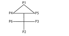
図2は、複数のセンサ20が配置された標章3の例を示す模式図である。図2に示す標章3は、楕円及びX字の立体的形状の結合からなる車両1のエンブレムである。標章3には、その所定の部位3a(図2中の網掛部分)に沿って複数のセンサ20(センサ20a~20e)が配置されている。図2に示す標章3では、所定の部位3aは、X字の立体的形状の部分である。
FIG. 2 is a schematic diagram showing an example of the mark 3 in which a plurality of sensors 20 are arranged. A mark 3 shown in FIG. 2 is an emblem of the vehicle 1 formed by a combination of an ellipse and an X-shaped three-dimensional shape. In the mark 3, a plurality of sensors 20 (sensors 20a to 20e) are arranged along a predetermined portion 3a (shaded portion in FIG. 2). In the mark 3 shown in FIG. 2, the predetermined part 3a is an X-shaped three-dimensional part.
複数のセンサ20は、ユーザの身体(手、指、足等)を検知すると、検知信号を制御部30に出力する非接触式又は接触式のセンサである。例えば、非接触式のセンサは、検知範囲に入ったユーザの身体に起因する静電容量の変化からユーザの身体を検知する静電容量センサであり、接触式のセンサは、センサにかかる圧力の変化によりユーザの身体を検知する圧力センサやメンブレンセンサ等である。なお、複数のセンサ20として、赤外線センサや、超音波センサ、光電センサ、レーザセンサ、カメラ等を用いてもよい。また、検知信号は1ビット値を有する信号であってもよく、この場合、複数のセンサ20は、ユーザの身体を検知した場合に「1」の値を制御部30に出力する。複数のセンサ20は、各センサ20a~20eの位置と、各センサ20a~20eがユーザの身体を検知するタイミングとから、所定の部位3aにおけるユーザの身体の動きを検知することができる。例えば、複数のセンサ20は、各センサ20a~20e間におけるユーザの身体の移動順序を検知することができる。
The plurality of sensors 20 are non-contact or contact sensors that output a detection signal to the control unit 30 when a user's body (hand, finger, foot, etc.) is detected. For example, a non-contact type sensor is a capacitance sensor that detects a user's body from a change in capacitance caused by the user's body that has entered the detection range, and a contact type sensor is a sensor that detects the pressure applied to the sensor. A pressure sensor, a membrane sensor, or the like that detects the user's body based on a change. As the plurality of sensors 20, an infrared sensor, an ultrasonic sensor, a photoelectric sensor, a laser sensor, a camera, or the like may be used. Further, the detection signal may be a signal having a 1-bit value. In this case, the plurality of sensors 20 output a value of “1” to the control unit 30 when detecting the user's body. The plurality of sensors 20 can detect the movement of the user's body at the predetermined portion 3a from the position of each sensor 20a to 20e and the timing at which each of the sensors 20a to 20e detects the user's body. For example, the plurality of sensors 20 can detect the order of movement of the user's body between the sensors 20a to 20e.
図3は、開閉検知装置10及び開閉体ECU4等のブロック図である。開閉検知装置10は、複数のセンサ20及び制御部30からなる。制御部30は、入力インターフェース(I/F)31、RAM(Random Access Memory)32、ROM(Read Only Memory)33、CPU(Central Processing Unit)34及び出力I/F35を備えるコンピュータである。なお、後述する制御部30の機能は、上記構成31~35を用いたソフトウェア処理によって実現されてもよいし、詳細な説明は省略するがロジック回路を用いたハードウェア処理によって実現されるようにしてもよい。
FIG. 3 is a block diagram of the open / close detection device 10 and the open / close body ECU 4 and the like. The open / close detection device 10 includes a plurality of sensors 20 and a control unit 30. The control unit 30 is a computer that includes an input interface (I / F) 31, a RAM (Random Access Memory) 32, a ROM (Read Only Memory) 33, a CPU (Central Processing Unit) 34, and an output I / F 35. The function of the control unit 30 to be described later may be realized by software processing using the above-described configurations 31 to 35, or may be realized by hardware processing using a logic circuit although detailed description is omitted. May be.
入力I/F31は、複数のセンサ20からの検知信号を入力し、CPU34で処理可能なデータに変換し、当該データはRAM32に一時的に記憶される。CPU34は、ROM33に予め記憶された所定のプログラムに基づき当該データを処理し、その処理結果を出力I/F35を介して開閉体ECU4に出力する。言い換えると、制御部30は、複数のセンサ20からの検知信号を基に開閉体2に係るユーザの開閉意思を判断し、開閉体ECU4に開閉体2の開作動又は閉作動を指示する信号(「作動トリガ信号」と称する。)を出力する。作動トリガ信号は、1ビット値を有する信号であってもよいし、複数のビットを有する信号であってもよい。また、複数のセンサ20と制御部30との通信は、シリアル通信であってもよいし、パラレル通信であってもよい。
The input I / F 31 receives detection signals from the plurality of sensors 20 and converts them into data that can be processed by the CPU 34, and the data is temporarily stored in the RAM 32. The CPU 34 processes the data based on a predetermined program stored in advance in the ROM 33, and outputs the processing result to the opening / closing body ECU 4 via the output I / F 35. In other words, the control unit 30 determines the user's intention to open / close the opening / closing body 2 based on the detection signals from the plurality of sensors 20, and instructs the opening / closing body ECU 4 to open or close the opening / closing body 2. (Referred to as “actuation trigger signal”). The activation trigger signal may be a signal having a 1-bit value or a signal having a plurality of bits. The communication between the plurality of sensors 20 and the control unit 30 may be serial communication or parallel communication.
開閉体ECU4は、開閉検知装置10から作動トリガ信号を入力すると、開閉体2の開閉状況に応じて開閉体駆動装置5のモータ5aに印加される電圧の極性を変更し、モータ5aの回転作動及び回転方向(正転又は逆転)を制御する。例えば、開閉体ECU4は、開閉体2がすでに閉まっていると判断した場合には、開閉体2の開作動が要求されていることになるため、モータ5aを正転させる。また、開閉体ECU4は、開閉体2がすでに開いていると判断した場合には、開閉体2の閉作動が要求されているため、モータ5aを逆転させる。ここで、限定されないが、モータ5aの正転が開閉体2の開作動に対応し、モータ5aの逆転が開閉体2の閉作動に対応するとする。また、開閉体ECU4は、前回の開閉体2の開閉作動の際に、開閉体2の開閉状態を記憶しておき、それを開閉体2の開閉状態を判断するために用いるようにするとよい。モータ5aの回転は、駆動機構5bを介して開閉体2に伝わり、開閉体2を開作動又は閉作動させる。
When the opening / closing body ECU 4 receives an operation trigger signal from the opening / closing detection device 10, the opening / closing body ECU 4 changes the polarity of the voltage applied to the motor 5 a of the opening / closing body driving device 5 according to the opening / closing state of the opening / closing body 2. And the direction of rotation (forward or reverse) is controlled. For example, when the opening / closing body ECU 4 determines that the opening / closing body 2 has already been closed, the opening operation of the opening / closing body 2 is required, so the motor 5a is rotated forward. When the opening / closing body ECU 4 determines that the opening / closing body 2 is already open, the opening / closing body 2 is requested to close, so the motor 5a is reversed. Here, although not limited, it is assumed that the forward rotation of the motor 5 a corresponds to the opening operation of the opening / closing body 2, and the reverse rotation of the motor 5 a corresponds to the closing operation of the opening / closing body 2. The opening / closing body ECU 4 may store the opening / closing state of the opening / closing body 2 at the time of the previous opening / closing operation of the opening / closing body 2, and use it for determining the opening / closing state of the opening / closing body 2. The rotation of the motor 5a is transmitted to the opening / closing body 2 via the drive mechanism 5b, and opens / closes the opening / closing body 2.
なお、開閉体2がトーションスプリングやガスダンパーを備えたバックドアである場合には、開閉体ECU4は、開閉検知装置10からユーザの開意思に係る作動トリガ信号を入力すると、当該バックドアのロックを解除するよう構成される。これにより、トーションスプリングやガスダンパーの力により当該バックドアは開作動することになる。また、開閉体2の開閉状態を判断する手段を開閉検知装置10に設け、開閉検知装置10が開閉体ECU4に開閉体2の開閉方向の情報とともに作動トリガ信号を出力するようにしてもよい。
When the opening / closing body 2 is a back door provided with a torsion spring or a gas damper, when the opening / closing body ECU 4 inputs an operation trigger signal related to the user's opening intention from the opening / closing detection device 10, the opening / closing body ECU 4 locks the back door. Configured to release. As a result, the back door is opened by the force of the torsion spring and the gas damper. Further, means for determining the open / close state of the open / close body 2 may be provided in the open / close detection device 10 so that the open / close detection device 10 outputs an operation trigger signal to the open / close body ECU 4 together with information on the open / close direction of the open / close body 2.
次に、図4A、図4B及び図5を用いて、開閉検知装置10によるユーザの開閉意思の判断方法について説明する。なお、説明を簡単にするために、以下では、ユーザの開意思に基づく開閉体2の開作動について説明するが、これに限定されるものではない。
Next, a method for determining the user's intention to open / close by the open / close detection device 10 will be described with reference to FIGS. 4A, 4B, and 5. FIG. In order to simplify the description, the opening operation of the opening / closing body 2 based on the user's intention to open will be described below, but the present invention is not limited to this.
本実施形態では、ユーザは、身体(指や手等)で標章3の所定の部位3aをなぞる動作をすることにより、開閉検知装置10にユーザの開閉体2に対する開意思を伝えることができる。このとき、開閉検知装置10の複数のセンサ20の各センサ20a~20eは、ユーザによる標章3の所定の部位3aをなぞる動作の順(「なぞり順」と称する。)にユーザの身体を検知していくことになり、制御部30には、複数のセンサ20の各センサ20a~20eから所定の部位3aのなぞり順に検知信号が入力されることになる。
In the present embodiment, the user can convey the user's intention to open the opening / closing body 2 to the opening / closing detection device 10 by performing an action of tracing the predetermined part 3a of the mark 3 with the body (finger, hand, etc.). . At this time, each of the sensors 20a to 20e of the plurality of sensors 20 of the open / close detection device 10 detects the user's body in the order of the user's action of tracing the predetermined part 3a of the mark 3 (referred to as "tracing order"). As a result, detection signals are input to the control unit 30 from the sensors 20a to 20e of the plurality of sensors 20 in the tracing order of the predetermined part 3a.
ここで、「なぞる」(又は「なぞり」)には、標章3の所定の部位3aにユーザの身体を接触させながら(接触状態で)所定の部位3aに沿って動かすという意味が含まれる。さらに、「なぞる」(又は「なぞり」)には、ユーザの身体を所定の部位3aから浮かした状態で(非接触状態で)、所定の部位3aに沿って動かすという意味も含まれる。複数のセンサ20として接触式のセンサを用いている場合には、ユーザは身体を所定の部位3aに接触させる必要があるが、非接触のセンサを用いている場合には、ユーザは身体を所定の部位3aに接触させる必要はない。
Here, “tracing” (or “tracing”) includes the meaning of moving along the predetermined portion 3a while the user's body is in contact with the predetermined portion 3a of the mark 3 (in a contact state). Furthermore, “tracing” (or “tracing”) also includes the meaning of moving the user's body along the predetermined portion 3a in a state of being lifted from the predetermined portion 3a (in a non-contact state). When a contact-type sensor is used as the plurality of sensors 20, the user needs to bring the body into contact with the predetermined part 3a. However, when a non-contact sensor is used, the user determines the body in advance. There is no need to contact the part 3a.
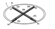
例えば、図4Aに示すように、ユーザが標章3の所定の部位3aを、X字の書き順のようにP1からP2及びP3からP4になぞることにより、センサ20a、20b、20c、20d、20b、20eは、順に検知信号を制御部30に出力する。この場合、図4Bのタイミングチャートに示すように、制御部30は、時刻t1にセンサ20aから検知信号を入力し、時刻t2にセンサ20bから検知信号を入力する。続いて、制御部30は、時刻t3にセンサ20cから検知信号を入力し、時刻t4にセンサ20dから検知信号を入力し、時刻t5にセンサ20bから検知信号を入力し、時刻t6にセンサ20eから検知信号を入力する。なお、当該なぞり順は、ユーザの好みに合わせて適宜設定できるように構成されるようにしてもよい。
For example, as shown in FIG. 4A, the user traces the predetermined part 3a of the mark 3 from P1 to P2 and from P3 to P4 like the writing order of the letter X, so that the sensors 20a, 20b, 20c, 20d, 20b and 20e output a detection signal to the control part 30 in order. In this case, as shown in the timing chart of FIG. 4B, the control unit 30 inputs a detection signal from the sensor 20a at time t1, and inputs a detection signal from the sensor 20b at time t2. Subsequently, the control unit 30 inputs a detection signal from the sensor 20c at time t3, inputs a detection signal from the sensor 20d at time t4, inputs a detection signal from the sensor 20b at time t5, and from the sensor 20e at time t6. Input the detection signal. Note that the tracing order may be configured so as to be appropriately set according to the user's preference.
図5は、ROM33に予め記憶されたプログラムに基づき制御部30のCPU34により実行されるユーザの開意思の判断処理に係るフローチャートである。なお、図5のフローチャートは、開閉検知装置10が車両1のバッテリから電源の供給を受けたときからスタートし、例えばミリ秒オーダーの周期で繰り返されるようにしてもよい。また、なぞり順の最初に相当するセンサ20aがユーザの身体を検知するまでは制御部30に供給する電力を低減しておき、検知後に電力の供給を増加させて本格的に当該判断処理が開始されるようにすると、電力の削減になる。
FIG. 5 is a flowchart relating to a determination process of the user's intention to open, which is executed by the CPU 34 of the control unit 30 based on a program stored in the ROM 33 in advance. 5 may be started when the open / close detection device 10 is supplied with power from the battery of the vehicle 1, and may be repeated, for example, in a cycle on the order of milliseconds. Further, the power supplied to the control unit 30 is reduced until the sensor 20a corresponding to the first in the tracing order detects the user's body, and the determination process starts in earnest by increasing the power supply after the detection. Doing so will result in a reduction in power.
まず、ステップS1で、制御部30は、標章3の所定の部位3aのなぞり順の最初の位置に相当するセンサ20aから検知信号を入力したかどうかを判断する。センサ20aからの検知信号の入力があった場合(ステップS1でYes)、ステップS2で、制御部30は、当該なぞり順の次の位置に相当するセンサ20bから検知信号を入力したかどうかを判断する。センサ20bからの検知信号を入力していない場合(ステップS2でNo)、ステップS3で、制御部30は、センサ20aからの検知信号を入力してから所定の時間が経過したかどうかを判断する。ここで、所定の時間は1秒程度であってもよいし、ミリ秒からマイクロ秒オーダーの値であってもよく、ユーザの利便性等を考慮して設定される。所定の時間が経過したと判断した場合(ステップS3でYes)、ステップS9で、制御部30は、警告音や警告光等を発生し、開作動が失敗したことをユーザに伝えるようにしてもよい。なお、ステップS9は省略してもよい。
First, in step S1, the control unit 30 determines whether or not a detection signal is input from the sensor 20a corresponding to the first position in the tracing order of the predetermined part 3a of the mark 3. When the detection signal is input from the sensor 20a (Yes in Step S1), in Step S2, the control unit 30 determines whether the detection signal is input from the sensor 20b corresponding to the next position in the tracing order. To do. When the detection signal from the sensor 20b is not input (No in step S2), in step S3, the control unit 30 determines whether or not a predetermined time has elapsed since the detection signal from the sensor 20a was input. . Here, the predetermined time may be about 1 second or may be a value on the order of milliseconds to microseconds, and is set in consideration of user convenience and the like. When it is determined that the predetermined time has elapsed (Yes in step S3), in step S9, the control unit 30 generates a warning sound, a warning light, or the like so as to notify the user that the opening operation has failed. Good. Note that step S9 may be omitted.
当該所定の時間が経過する前にセンサ20bからの検知信号の入力があった場合(ステップS2でYes)、ステップS4で、制御部30は、当該なぞり順のさらに次の位置に相当するセンサ20cから検知信号を入力したかどうかを判断する。センサ20cからの検知信号を入力していない場合(ステップS4でNo)、ステップS5で、制御部30は、センサ20bからの検知信号を入力してから所定の時間が経過したかどうかを判断する。以下同様のことがセンサ20d、20bに対して繰り返される。そして、ステップS6で、制御部30は、当該なぞり順の最後の位置に相当するセンサ20eから検知信号を入力したかどうかを判断する。センサ20eからの検知信号を入力していない場合(ステップS6でNo)、ステップS7で、制御部30は、センサ20eからの検知信号を入力してから当該所定の時間が経過したかどうかを判断する。
If a detection signal is input from the sensor 20b before the predetermined time has elapsed (Yes in step S2), in step S4, the control unit 30 determines that the sensor 20c corresponds to the next position in the tracing order. It is determined whether or not a detection signal is input from. When the detection signal from the sensor 20c is not input (No in step S4), in step S5, the control unit 30 determines whether or not a predetermined time has elapsed since the detection signal from the sensor 20b was input. . The same is repeated for the sensors 20d and 20b. In step S6, the control unit 30 determines whether a detection signal is input from the sensor 20e corresponding to the last position in the tracing order. When the detection signal from the sensor 20e is not input (No in step S6), in step S7, the control unit 30 determines whether or not the predetermined time has elapsed since the detection signal from the sensor 20e was input. To do.
所定の時間が経過する前にセンサ20eからの検知信号を入力した場合(ステップS6でYes)、ステップS8で、制御部30は、ユーザの開閉体2に対する開意思を判断し、作動トリガ信号を開閉体ECU4に出力する。ここで、制御部30は、作動トリガ信号を出力する際に、確認音等を発生し、ユーザに開作動が成功したことを知らせたり、ユーザに開閉体2から離れるように促すようにしてもよい。
When the detection signal from the sensor 20e is input before the predetermined time has elapsed (Yes in Step S6), in Step S8, the control unit 30 determines the user's intention to open the opening / closing body 2 and outputs an operation trigger signal. Output to the opening / closing body ECU4. Here, when the operation trigger signal is output, the control unit 30 generates a confirmation sound or the like to inform the user that the opening operation has been successful or to prompt the user to leave the opening / closing body 2. Good.
このようにして、開閉検知装置10の制御部30は、複数のセンサ20からのなぞり順を示す検知信号を基に、開閉体2に係るユーザの開意思を判断することができる。なお、本実施形態では、検知信号の入力の有無を判断する各ステップで、検知信号の入力が無い場合に、所定の時間が経過したか否かの判断を行っている。しかし、これに限定されず、最初の判断ステップから最後の判断ステップまでの合計時間が所定の時間を超えていたら作動トリガ信号を出力しないという構成にしてもよい。
Thus, the control unit 30 of the open / close detection device 10 can determine the user's intention to open the open / close body 2 based on the detection signals indicating the tracing order from the plurality of sensors 20. In the present embodiment, in each step of determining whether or not a detection signal is input, it is determined whether or not a predetermined time has elapsed when no detection signal is input. However, the present invention is not limited to this, and the operation trigger signal may not be output if the total time from the first determination step to the last determination step exceeds a predetermined time.
なお、以下のようにして、制御部30は、ユーザの開意思を判断してもよい。表1に示すように、開閉検知装置10の制御部30は、複数のセンサ20からの検知信号を入力した順にRAM32上にテーブルを作成し、ROM33に予め記憶された作動条件テーブルと当該作成したテーブルとを比較する。両者が一致する場合にユーザの開閉作動意思があると判断し、制御部30は、作動トリガ信号を開閉体ECU4に出力するようにしてもよい。
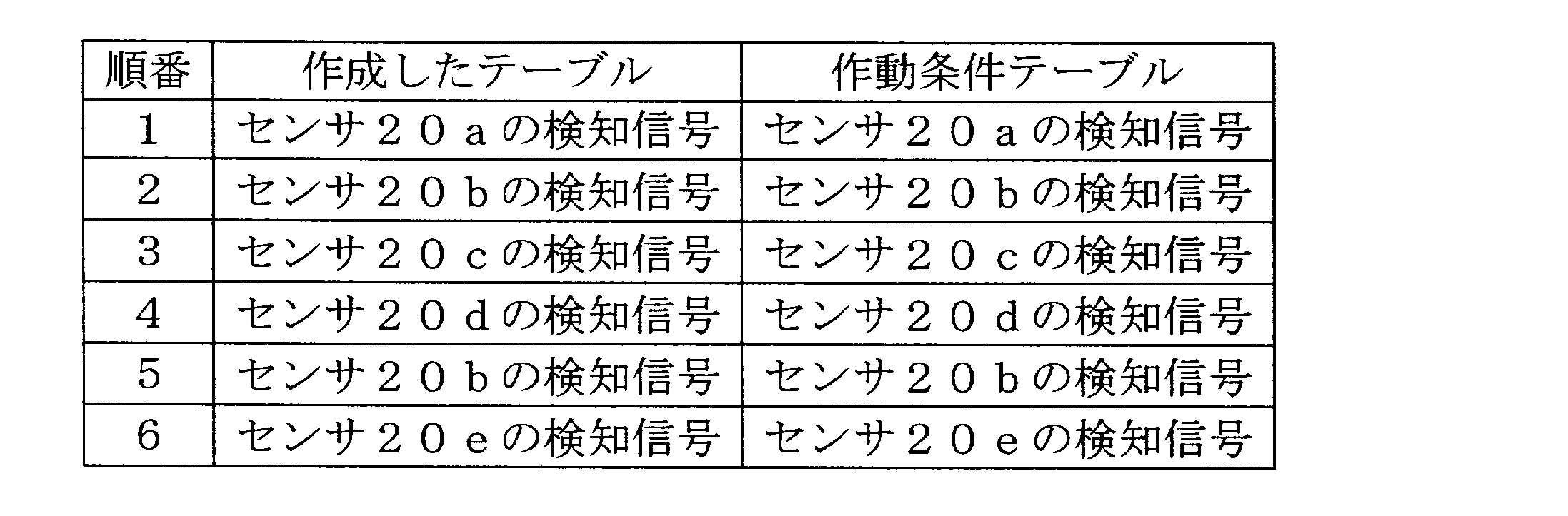
The control unit 30 may determine the user's intention to open as follows. As shown in Table 1, the control unit 30 of the open / close detection device 10 creates a table on the RAM 32 in the order in which detection signals from the plurality of sensors 20 are input, and creates the operation condition table stored in advance in the ROM 33 and the table. Compare with table. If the two coincide, it is determined that the user has an intention to open / close, and the control unit 30 may output an operation trigger signal to the opening / closing body ECU 4.
また、表2に示すように、作成したテーブルと作動条件テーブルとがある程度(例えば8~9割程度等)一致していれば、制御部30は、ユーザの開意思があると判断し、作動トリガ信号を開閉体ECU4に出力するようにしてもよい。

In addition, as shown in Table 2, if the created table and the operation condition table agree to some extent (for example, about 80 to 90%), the control unit 30 determines that the user has an intention to open and operates. You may make it output a trigger signal to opening-closing body ECU4.
以上のように、本実施形態に係る開閉検知装置10は、車両1のユーザによる標章3の所定の部位3aのなぞる動作の順を検知した複数のセンサ20から、標章3の所定の部位3aのなぞり順の検知信号が入力されると、車両1の開閉体2の開閉作動を指示する作動トリガ信号を出力するように構成されている。そのため、複数のセンサ20がその近くを通り抜けた車両や構造物や人を誤検知してしまっても、それがなぞり順に誤検知されることは稀であるため、誤って開閉体2が開閉作動される可能性が低減される。また、複数のセンサ20の数を増やしていくことで、誤検知による開閉体の誤作動をより低減することができる。この場合、ユーザは複数のセンサ20をなぞる順番を覚えておくのが大変であると思われるかもしれないが、ユーザは、標章3に沿ってなぞる動作をすればよいだけであるため、殊更なぞり順を覚えていなくてもよく、ユーザの利便性が向上する。また、ユーザは、開閉体2を開閉作動させるために、標章3の所定の部位3aをなぞればよいため、ワイヤレスキーを取り出して操作したり、開閉のための複雑な動作を覚えておく必要がない。とくに、標章3の所定の部位3aが文字等を表している場合には、その書き順をなぞり順として設定しておくと、ユーザは特別な動作を覚える必要がない。また、所定の部位3aがドアアウトサイドハンドル等である場合には、開閉体2の開閉作動方向をなぞり順として設定しておくことにより、ユーザは自然な動作により開閉体2の開閉作動を行うことができる。また、複数のセンサ20として非接触センサを用いることで、ユーザは、車両1に触れる必要がないため、手や指等が汚れる心配をする必要がない。また、複数のセンサ20を標章3(特にエンブレム)の所定の部位3aに沿って埋め込むことにより、複数のセンサ20のための部材を別途設ける必要がなく、また複数のセンサ20が車両1の外観に表れてこないため、意匠上好ましい利点がある。
As described above, the open / close detection device 10 according to the present embodiment includes the predetermined part of the mark 3 from the plurality of sensors 20 that detect the order of the movement of the predetermined part 3a of the mark 3 by the user of the vehicle 1. When the detection signal of the tracing order 3a is input, an operation trigger signal that instructs the opening / closing operation of the opening / closing body 2 of the vehicle 1 is output. For this reason, even if a plurality of sensors 20 erroneously detect a vehicle, structure, or person passing through the sensor 20, it is rare that the sensor 20 is erroneously detected in the tracing order. The possibility of being reduced is reduced. Further, by increasing the number of the plurality of sensors 20, it is possible to further reduce the malfunction of the opening / closing body due to erroneous detection. In this case, it may seem difficult for the user to remember the order in which the plurality of sensors 20 are traced. However, since the user only has to perform the tracing operation along the mark 3, it is particularly necessary to change the order. It is not necessary to remember the tracing order, and the convenience for the user is improved. In addition, since the user only has to trace the predetermined part 3a of the mark 3 in order to open and close the opening / closing body 2, the user takes out and operates the wireless key or remembers a complicated operation for opening and closing. There is no need. In particular, when the predetermined part 3a of the mark 3 represents a character or the like, if the writing order is set as the tracing order, the user does not need to learn a special operation. Further, when the predetermined portion 3a is a door outside handle or the like, by setting the opening / closing operation direction of the opening / closing body 2 as a tracing order, the user performs the opening / closing operation of the opening / closing body 2 by a natural operation. be able to. Further, by using non-contact sensors as the plurality of sensors 20, the user does not need to touch the vehicle 1, so there is no need to worry about getting hands, fingers, etc. dirty. Further, by embedding the plurality of sensors 20 along the predetermined portion 3a of the mark 3 (particularly the emblem), it is not necessary to separately provide a member for the plurality of sensors 20, and the plurality of sensors 20 are provided on the vehicle 1. Since it does not appear in the appearance, there is a favorable advantage in design.
[第2実施形態]
次に、図6A、図6B、図7及び図8を用いて、本発明の第2実施形態に係る開閉検知装置10について説明する。第1実施形態と比べて、本実施形態に係る開閉検知装置10の制御部30は、認証部36及び離隔判断部37をさらに備える。 [Second Embodiment]
Next, the open /close detection device 10 according to the second embodiment of the present invention will be described with reference to FIGS. 6A, 6B, 7 and 8. FIG. Compared with the first embodiment, the control unit 30 of the open / close detection device 10 according to the present embodiment further includes an authentication unit 36 and a separation determination unit 37.
次に、図6A、図6B、図7及び図8を用いて、本発明の第2実施形態に係る開閉検知装置10について説明する。第1実施形態と比べて、本実施形態に係る開閉検知装置10の制御部30は、認証部36及び離隔判断部37をさらに備える。 [Second Embodiment]
Next, the open /
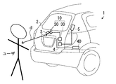
図6Aに示すように、本実施形態では、標章3の所定の部位3aに沿って配置された複数のセンサ20(20a~20e)に加えて、距離測定センサ22が配置されている。距離測定センサ22は、ユーザの身体に照射した赤外線の反射を基に、距離測定センサ22から、言い換えると標章3が取り付けられた開閉体2からユーザの身体までの距離dを測定し、距離情報を制御部30に出力する赤外線センサである。なお、距離測定センサ22として、超音波センサや、レーザセンサ等を用いてもよい。また、距離測定センサ22は、標章3に配置されている構成に限らず、開閉体2からユーザの身体までの距離を測定可能な開閉体2又は車両1の任意の位置に配置されていてもよい。また、詳細な説明は省略するが、距離測定センサ22を設ける構成に限らず、距離測定センサ22を設ける代わりに、別の用途で車両1に既に設けられているクリアランスソナー等の情報を用いてもよい。
As shown in FIG. 6A, in the present embodiment, in addition to the plurality of sensors 20 (20a to 20e) arranged along the predetermined portion 3a of the mark 3, a distance measuring sensor 22 is arranged. The distance measurement sensor 22 measures the distance d from the distance measurement sensor 22, in other words, the opening / closing body 2 to which the mark 3 is attached, to the user's body, based on the reflection of infrared rays irradiated to the user's body. It is an infrared sensor that outputs information to the control unit 30. As the distance measurement sensor 22, an ultrasonic sensor, a laser sensor, or the like may be used. The distance measuring sensor 22 is not limited to the configuration arranged in the mark 3, and is arranged at any position of the opening / closing body 2 or the vehicle 1 that can measure the distance from the opening / closing body 2 to the user's body. Also good. Although detailed description is omitted, the present invention is not limited to the configuration in which the distance measurement sensor 22 is provided. Instead of providing the distance measurement sensor 22, information such as clearance sonar already provided in the vehicle 1 for another use is used. Also good.
図6Bに示すように、車両1には認証ECU40が設置され、認証ECU40は、開閉検知装置10の制御部30に接続されている。ユーザが車両1から所定の範囲内に入ったときに、認証ECU40は、ユーザが有するスマートエントリーキーと無線通信し、当該スマートエントリーキーを有するユーザが車両1の正当な使用者であることを判断する(認証成功)。そして、認証ECU40は、当該認証成立に係る認証情報を制御部30に送信する。
As shown in FIG. 6B, an authentication ECU 40 is installed in the vehicle 1, and the authentication ECU 40 is connected to the control unit 30 of the open / close detection device 10. When the user enters the predetermined range from the vehicle 1, the authentication ECU 40 wirelessly communicates with the smart entry key that the user has, and determines that the user having the smart entry key is a valid user of the vehicle 1. Yes (authentication successful). And authentication ECU40 transmits the authentication information which concerns on the said authentication establishment to the control part 30. FIG.
認証部36は、認証ECU40からの認証情報を基に、複数のセンサ20に対してなぞる動作をしているユーザが認証された者であるかどうかを判断する。ユーザが認証されていないと判断されると、制御部30は、作動トリガ信号を出力しないように構成されている。
The authentication unit 36 determines whether or not the user who performs the tracing operation with respect to the plurality of sensors 20 is an authenticated person based on the authentication information from the authentication ECU 40. When it is determined that the user is not authenticated, the control unit 30 is configured not to output an operation trigger signal.
また、離隔判断部37は、距離測定センサ22からの距離情報を基に、距離測定センサ22から、言い換えると標章3が取り付けられた開閉体2からユーザの身体までの距離dが、閾値距離dth以上であるかどうかを判断する。距離dが閾値距離dthより短いと判断されると、制御部30は、作動トリガ信号を出力しないように構成されている。ここで、閾値距離dthは、開閉体2の開閉軌道に応じて設定するとよい。つまり、ユーザの身体が、開閉体2から閾値距離dth以上離れることにより開閉作動の際に開閉体2と衝突することがないように、閾値距離dthを設定する。
In addition, the distance determination unit 37 determines the distance d from the distance measurement sensor 22, in other words, the opening / closing body 2 to which the mark 3 is attached, to the user's body based on the distance information from the distance measurement sensor 22. It is determined whether or not it is greater than d th . If it is determined that the distance d is shorter than the threshold distance d th , the control unit 30 is configured not to output an operation trigger signal. Here, the threshold distance dth may be set according to the opening / closing path of the opening / closing body 2. That is, the threshold distance d th is set so that the user's body does not collide with the opening / closing body 2 during the opening / closing operation due to being separated from the opening / closing body 2 by the threshold distance d th or more.
図8は、本実施形態に係るユーザの開閉意思の判断処理に係るフローチャートである。なお、図5のフローチャートと同じ処理を行うステップについては同一符号を付しており、再度説明はしない。
FIG. 8 is a flowchart according to the determination process of the user's intention to open and close according to the present embodiment. In addition, the same code | symbol is attached | subjected about the step which performs the same process as the flowchart of FIG. 5, and it does not explain again.
ステップS10で、制御部30の認証部36は、認証ECU40からの認証情報を基に、複数のセンサ20をなぞっているユーザが車両1の正当な使用者であるとの認証が成功しているかどうか判断する。認証が成功していない場合(ステップS10でNo)、フローは中断され、ユーザに対して警告が発生される(ステップS9)。なお、ステップS9を省略してもよい。認証が成功している場合(ステップS10でYes)、ステップS2~S6が行われていく。
In step S <b> 10, the authentication unit 36 of the control unit 30 has successfully authenticated that the user tracing the plurality of sensors 20 is a valid user of the vehicle 1 based on the authentication information from the authentication ECU 40. Judge whether. If the authentication is not successful (No in step S10), the flow is interrupted and a warning is issued to the user (step S9). Note that step S9 may be omitted. If the authentication is successful (Yes in step S10), steps S2 to S6 are performed.
ステップS11で、制御部30の離隔判断部37は、距離測定センサ22からの距離情報を基に、開閉体2からユーザの身体までの距離dが閾値距離dth以上であるかどうか判断する。距離dが閾値距離dthより短い場合(ステップS11でNo)、ステップS12で、制御部30は所定の時間経過したかどうか判断する。ここでの所定の時間は、ユーザの身体が開閉体2から離れるのに十分な時間として設定するとよいため、ステップS3、S7の所定の時間よりも長いものとなる。そして、距離dが閾値距離dth以上である場合(ステップS11でYes)、制御部30は、開閉体ECU4に作動トリガ信号を出力する。
In step S <b> 11, the separation determination unit 37 of the control unit 30 determines whether the distance d from the opening / closing body 2 to the user's body is greater than or equal to the threshold distance d th based on the distance information from the distance measurement sensor 22. When the distance d is shorter than the threshold distance d th (No in step S11), in step S12, the control unit 30 determines whether a predetermined time has elapsed. The predetermined time here may be set as a time sufficient for the user's body to move away from the opening / closing body 2, and thus is longer than the predetermined time in steps S3 and S7. When the distance d is equal to or greater than the threshold distance d th (Yes in Step S11), the control unit 30 outputs an operation trigger signal to the opening / closing body ECU 4.
以上のように、本実施形態に係る開閉検知装置10は、上記利点に加えて、正当な車両1の使用者でない者による操作があったとしても、開閉体2の作動トリガ信号を出力しないように構成されているため、防犯性能を向上させることができる。また、開閉検知装置10は、ユーザの身体が開閉体2から所定の閾値距離dth以上離れないと開閉体2の作動トリガ信号を出力しないように構成されているため、開閉作動の際にユーザの身体が開閉体2に衝突する可能性を低減することができる。
As described above, in addition to the above advantages, the open / close detection device 10 according to the present embodiment does not output an operation trigger signal for the open / close body 2 even if there is an operation by a person who is not a valid user of the vehicle 1. Therefore, the crime prevention performance can be improved. The opening / closing detection device 10 is configured not to output an operation trigger signal of the opening / closing body 2 unless the user's body is separated from the opening / closing body 2 by a predetermined threshold distance dth or more. The possibility that the body of the vehicle collides with the opening / closing body 2 can be reduced.
(その他の実施形態)
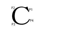
図9A~図9Dは、標章3のバリエーションを示す模式図であり、図中P1乃至P6はその順になぞることで作動トリガ信号が出力されることを示す。図9Aに示すように、標章3として複雑な図形を用いて、セキュリティを向上させてもよい。また、図9Bに示すように、標章3を文字「T」のように構成し、その書き順のとおりになぞることで作動トリガ信号が出力されるようにしてもよい。また、図9C及び図9Dに示すように、標章3を文字「C」や図形Oに設定し、一筆書きの要領でなぞる動作を行うことにより作動トリガ信号が出力されるようにしてもよい。 (Other embodiments)
FIGS. 9A to 9D are schematic diagrams showing variations of themark 3, in which P1 to P6 indicate that an operation trigger signal is output by tracing in that order. As shown in FIG. 9A, security may be improved by using a complicated figure as the mark 3. Further, as shown in FIG. 9B, the mark 3 may be configured as a letter “T”, and the operation trigger signal may be output by tracing in the order of writing. Further, as shown in FIGS. 9C and 9D, the operation trigger signal may be output by setting the mark 3 to the character “C” or the figure O and performing the tracing operation in the manner of one-stroke writing. .
図9A~図9Dは、標章3のバリエーションを示す模式図であり、図中P1乃至P6はその順になぞることで作動トリガ信号が出力されることを示す。図9Aに示すように、標章3として複雑な図形を用いて、セキュリティを向上させてもよい。また、図9Bに示すように、標章3を文字「T」のように構成し、その書き順のとおりになぞることで作動トリガ信号が出力されるようにしてもよい。また、図9C及び図9Dに示すように、標章3を文字「C」や図形Oに設定し、一筆書きの要領でなぞる動作を行うことにより作動トリガ信号が出力されるようにしてもよい。 (Other embodiments)
FIGS. 9A to 9D are schematic diagrams showing variations of the
また、開閉検知装置10は、車両1に搭載された速度センサ(不図示)からの情報を基に、車両1が所定の速度以上で走行しているときには、作動トリガ信号を出力しないように構成してもよい。また、開閉検知装置10の制御部30による開閉意思の判断は、ソフトウェア処理によって実現されてもよいし、ハードウェア処理によって実現されるようにしてもよい。
The open / close detection device 10 is configured not to output an operation trigger signal when the vehicle 1 is traveling at a predetermined speed or more based on information from a speed sensor (not shown) mounted on the vehicle 1. May be. The determination of the intention to open / close by the control unit 30 of the open / close detection device 10 may be realized by software processing or hardware processing.
この出願は2014年12月3日に出願された日本国特許出願第2014-245102号からの優先権を主張するものであり、その内容を引用してこの出願の一部とするものである。
This application claims priority from Japanese Patent Application No. 2014-245102 filed on Dec. 3, 2014, the contents of which are incorporated herein by reference.
1:車両、2:開閉体、3:標章、3a:標章の所定の部位、4:開閉体ECU、5:開閉体駆動装置、10:開閉検知装置、20:複数のセンサ、30:制御部
1: Vehicle, 2: Opening / closing body, 3: Mark, 3a: Predetermined part of the mark, 4: Opening / closing body ECU, 5: Opening / closing body driving device, 10: Opening / closing detection device, 20: Multiple sensors, 30: Control unit
Claims (5)
- 車両に取り付けられた標章の所定の部位に沿うように配置されるよう構成された複数のセンサと、
前記車両のユーザによる標章の所定の部位のなぞる動作の順を検知した前記複数のセンサから、前記所定の部位のなぞり順の検知信号が入力されると、前記車両の開閉体の開作動を指示する作動トリガ信号を出力する制御部とを備える開閉検知装置。 A plurality of sensors configured to be arranged along a predetermined portion of a mark attached to the vehicle;
When the detection signal of the tracing order of the predetermined part is input from the plurality of sensors that detect the order of the tracing operation of the predetermined part of the mark by the user of the vehicle, the opening / closing body of the vehicle is opened. An open / close detection device comprising: a control unit that outputs an instructing operation trigger signal. - 前記ユーザと前記標章との間の距離を検出する距離測定センサをさらに備え、
前記制御部は、前記距離測定センサからの距離情報を基に、前記ユーザと前記標章との間の距離が閾値距離より短いと判断すると、前記作動トリガ信号を出力しないように構成されている、請求項1に記載の開閉検知装置。 A distance measuring sensor for detecting a distance between the user and the mark;
The control unit is configured not to output the operation trigger signal when determining that the distance between the user and the mark is shorter than a threshold distance based on distance information from the distance measurement sensor. The open / close detection device according to claim 1. - 前記制御部は、前記ユーザが認証されていないと判断すると、前記作動トリガ信号を出力しないように構成されている、請求項1又は2に記載の開閉検知装置。 The open / close detection device according to claim 1 or 2, wherein the control unit is configured not to output the operation trigger signal when determining that the user is not authenticated.
- 前記標章は、前記車両のエンブレムである、請求項1乃至3のいずれか1項に記載の開閉検知装置。 The opening / closing detection device according to any one of claims 1 to 3, wherein the mark is an emblem of the vehicle.
- 前記複数のセンサは、非接触式のセンサである、請求項1乃至4のいずれか1項に記載の開閉検知装置。 The open / close detection device according to any one of claims 1 to 4, wherein the plurality of sensors are non-contact sensors.
Priority Applications (3)
| Application Number | Priority Date | Filing Date | Title |
|---|---|---|---|
| CN201580065839.6A CN107002447A (en) | 2014-12-03 | 2015-12-01 | The open-close detection apparatus of opening/closing body for vehicle |
| EP15864890.7A EP3228792B1 (en) | 2014-12-03 | 2015-12-01 | Opening/closing detection device for vehicle opening/closing member |
| US15/532,392 US10329829B2 (en) | 2014-12-03 | 2015-12-01 | Opening/closing detection device for vehicle opening/closing member |
Applications Claiming Priority (2)
| Application Number | Priority Date | Filing Date | Title |
|---|---|---|---|
| JP2014245102A JP6211506B2 (en) | 2014-12-03 | 2014-12-03 | Open / close detection device for vehicle opening / closing body |
| JP2014-245102 | 2014-12-03 |
Publications (1)
| Publication Number | Publication Date |
|---|---|
| WO2016088359A1 true WO2016088359A1 (en) | 2016-06-09 |
Family
ID=56091321
Family Applications (1)
| Application Number | Title | Priority Date | Filing Date |
|---|---|---|---|
| PCT/JP2015/005958 WO2016088359A1 (en) | 2014-12-03 | 2015-12-01 | Opening/closing detection device for vehicle opening/closing member |
Country Status (5)
| Country | Link |
|---|---|
| US (1) | US10329829B2 (en) |
| EP (1) | EP3228792B1 (en) |
| JP (1) | JP6211506B2 (en) |
| CN (1) | CN107002447A (en) |
| WO (1) | WO2016088359A1 (en) |
Cited By (1)
| Publication number | Priority date | Publication date | Assignee | Title |
|---|---|---|---|---|
| WO2019211760A1 (en) * | 2018-04-30 | 2019-11-07 | Tofilescu Pompilian | Camera based hands-free power liftgate |
Families Citing this family (14)
| Publication number | Priority date | Publication date | Assignee | Title |
|---|---|---|---|---|
| US9896353B2 (en) | 2011-11-04 | 2018-02-20 | Ppg Industries Ohio, Inc. | Hydrocarbon waste stream purification processes using microporous materials having filtration and adsorption properties |
| JP6211506B2 (en) * | 2014-12-03 | 2017-10-11 | アイシン精機株式会社 | Open / close detection device for vehicle opening / closing body |
| DE102016007357A1 (en) * | 2016-06-15 | 2017-12-21 | GM Global Technology Operations LLC (n. d. Ges. d. Staates Delaware) | Motor vehicle device with a movable window pane, motor vehicle with such a motor vehicle device and method for operating such a motor vehicle device |
| US10577851B2 (en) * | 2017-06-15 | 2020-03-03 | GM Global Technology Operations LLC | Automatic closure system with active distance control |
| US10533362B2 (en) | 2017-06-16 | 2020-01-14 | GM Global Technology Operations LLC | Systems and methods for memory and touch position window |
| DE102017128774B4 (en) * | 2017-12-04 | 2023-11-02 | Witte Automotive Gmbh | Optical sensor system for a motor vehicle |
| DE102017223726A1 (en) * | 2017-12-22 | 2019-06-27 | Volkswagen Aktiengesellschaft | Attachment for a vehicle and vehicle with such an attachment |
| CN109278506A (en) * | 2018-11-28 | 2019-01-29 | 奇瑞汽车股份有限公司 | A kind of automotive back door opening control system |
| CN112006624A (en) * | 2019-05-31 | 2020-12-01 | 青岛海尔洗碗机有限公司 | Dish washing machine and use method thereof |
| CN111114470A (en) * | 2020-01-06 | 2020-05-08 | 海拉(厦门)电气有限公司 | Automobile glass based on intelligent actuator and control method of trunk |
| JP7298520B2 (en) * | 2020-03-10 | 2023-06-27 | トヨタ自動車株式会社 | Getting off assistance device |
| CZ308790B6 (en) * | 2020-03-21 | 2021-05-19 | Brano A.S. | Door handle |
| US11872927B2 (en) * | 2020-05-15 | 2024-01-16 | Toyota Motor Engineering & Manufacturing North America, Inc. | Tail lamp back door/tailgate activation switch |
| CN113250578B (en) * | 2021-06-16 | 2022-12-09 | 上汽通用汽车有限公司 | Vehicle door control method, system, device and storage medium |
Citations (6)
| Publication number | Priority date | Publication date | Assignee | Title |
|---|---|---|---|---|
| JP2003531976A (en) * | 2000-04-26 | 2003-10-28 | ヴァレオ エレクトロニク | Vehicle equipped with a system capable of remotely controlling a door and a system capable of realizing such operation |
| JP2012530859A (en) * | 2009-06-18 | 2012-12-06 | アダック プラスティックス,インク. | Keyless entry system with concealable keypad |
| JP2014181499A (en) * | 2013-03-19 | 2014-09-29 | Mitsuba Corp | Door operation device |
| JP2014201966A (en) * | 2013-04-05 | 2014-10-27 | アイシン精機株式会社 | Auto-door operation device for vehicle |
| JP2014531534A (en) * | 2011-09-05 | 2014-11-27 | ブローゼ ファールツォイクタイレ ゲゼルシャフト ミット ベシュレンクテル ハフツング ウント コンパニ コマンディートゲゼルシャフト ハルシュタットBrose Fahrzeugteile GmbH & Co. KG, Hallstadt | Control system |
| DE102014004334A1 (en) * | 2014-03-26 | 2015-10-01 | Daimler Ag | Lighting element for a vehicle |
Family Cites Families (35)
| Publication number | Priority date | Publication date | Assignee | Title |
|---|---|---|---|---|
| US5140316A (en) * | 1990-03-22 | 1992-08-18 | Masco Industries, Inc. | Control apparatus for powered vehicle door systems |
| JP5150810B2 (en) | 2001-03-23 | 2013-02-27 | オプテックス株式会社 | Automatic door opening and closing control device |
| JP4546678B2 (en) | 2001-09-14 | 2010-09-15 | 千蔵工業株式会社 | Automatic door opener |
| CN1846038A (en) * | 2003-09-01 | 2006-10-11 | 松下电器产业株式会社 | Vehicle unlocking system |
| JP2006277522A (en) | 2005-03-30 | 2006-10-12 | Nec Corp | Information processor and method for authenticating information processor |
| US7410202B2 (en) * | 2006-02-06 | 2008-08-12 | Volkswagen Ag | Flat control element for controlling a vehicle component |
| US20070216517A1 (en) * | 2006-03-14 | 2007-09-20 | Denso International America, Inc. | Automatic vehicle door locking with seat occupant sensor |
| JP2008292445A (en) | 2006-10-24 | 2008-12-04 | Asmo Co Ltd | Foreign matter detecting device and opening-closing device |
| JP4915657B2 (en) | 2006-12-21 | 2012-04-11 | オプテックス株式会社 | Non-contact switch for automatic door |
| US7686378B2 (en) * | 2007-06-01 | 2010-03-30 | Gm Global Technology Operations, Inc. | Power swinging side door system and method |
| US8091280B2 (en) * | 2007-06-01 | 2012-01-10 | GM Global Technology Operations LLC | Arms full vehicle closure activation apparatus and method |
| WO2009014212A1 (en) * | 2007-07-26 | 2009-01-29 | Omron Corporation | Control device and method |
| DE102008063366B4 (en) * | 2008-12-30 | 2022-04-28 | Huf Hülsbeck & Fürst Gmbh & Co. Kg | Device for contactless actuation of a tailgate of a motor vehicle and method for actuating a tailgate of a motor vehicle and motor vehicle |
| JP5107458B2 (en) * | 2009-06-11 | 2012-12-26 | トヨタ自動車株式会社 | Electromagnetic coupling device and vehicle door |
| DE102010027509B4 (en) * | 2009-07-17 | 2023-12-21 | Huf Hülsbeck & Fürst Gmbh & Co. Kg | Sensor device and module unit for it |
| EP2314427B8 (en) * | 2009-10-23 | 2016-08-31 | First Sensor Mobility GmbH | Method and device for controlling electrical devices by means of motion detection |
| JP5360491B2 (en) * | 2009-11-13 | 2013-12-04 | アイシン精機株式会社 | Multifunctional camera system |
| US8964298B2 (en) * | 2010-02-28 | 2015-02-24 | Microsoft Corporation | Video display modification based on sensor input for a see-through near-to-eye display |
| DE102010060364A1 (en) | 2010-11-04 | 2012-05-10 | Huf Hülsbeck & Fürst Gmbh & Co. Kg | Method for a motor vehicle |
| FR2979873B1 (en) * | 2011-09-12 | 2013-10-04 | Valeo Securite Habitacle | METHOD FOR OPENING AN OPENING OF A MOTOR VEHICLE |
| US20140309893A1 (en) * | 2013-04-15 | 2014-10-16 | Flextronics Ap, Llc | Health statistics and communications of associated vehicle users |
| DE102012108004A1 (en) * | 2012-08-30 | 2014-03-06 | Huf Hülsbeck & Fürst Gmbh & Co. Kg | Safety system for a motor vehicle door of a motor vehicle with at least two sensors |
| US9382739B1 (en) * | 2013-03-15 | 2016-07-05 | August Home, Inc. | Determining right or left hand side door installation |
| CN109629953A (en) * | 2013-05-15 | 2019-04-16 | 麦格纳覆盖件有限公司 | For operating the method and system of the closure plate of vehicle |
| DE102013110506A1 (en) * | 2013-07-03 | 2015-01-08 | Huf Hülsbeck & Fürst Gmbh & Co. Kg | Detection method for actuation gestures |
| US9475369B2 (en) * | 2013-07-17 | 2016-10-25 | Aisin Seiki Kabushiki Kaisha | Vehicle door opening and closing apparatus and method of controlling the same |
| JP5788937B2 (en) * | 2013-08-30 | 2015-10-07 | アイシン精機株式会社 | Vehicle opening / closing body control apparatus and vehicle opening / closing system |
| EP2860704B1 (en) * | 2013-10-10 | 2016-04-27 | U-Shin France SAS | Method for opening a movable panel of the motor vehicle and corresponding opening control device |
| DE102014101198A1 (en) * | 2014-01-31 | 2015-08-06 | Huf Hülsbeck & Fürst Gmbh & Co. Kg | Emblem for a motor vehicle with an optical sensor system and method for this |
| JP6211506B2 (en) * | 2014-12-03 | 2017-10-11 | アイシン精機株式会社 | Open / close detection device for vehicle opening / closing body |
| US10365753B2 (en) * | 2015-09-23 | 2019-07-30 | Vais Technology Ltd. | Hands-free power liftgate opener |
| US9879463B2 (en) * | 2016-02-26 | 2018-01-30 | Waymo Llc | Device and method for powered closing of car doors |
| US10227810B2 (en) * | 2016-08-03 | 2019-03-12 | Ford Global Technologies, Llc | Priority driven power side door open/close operations |
| US9822553B1 (en) * | 2016-11-23 | 2017-11-21 | Gate Labs Inc. | Door tracking system and method |
| DE102018202343A1 (en) * | 2017-02-17 | 2018-08-23 | Magna Closures Inc. | POWER SWING DOOR WITH VIRTUAL HANDLE POST CONTROL |
-
2014
- 2014-12-03 JP JP2014245102A patent/JP6211506B2/en not_active Expired - Fee Related
-
2015
- 2015-12-01 US US15/532,392 patent/US10329829B2/en not_active Expired - Fee Related
- 2015-12-01 WO PCT/JP2015/005958 patent/WO2016088359A1/en active Application Filing
- 2015-12-01 EP EP15864890.7A patent/EP3228792B1/en active Active
- 2015-12-01 CN CN201580065839.6A patent/CN107002447A/en active Pending
Patent Citations (6)
| Publication number | Priority date | Publication date | Assignee | Title |
|---|---|---|---|---|
| JP2003531976A (en) * | 2000-04-26 | 2003-10-28 | ヴァレオ エレクトロニク | Vehicle equipped with a system capable of remotely controlling a door and a system capable of realizing such operation |
| JP2012530859A (en) * | 2009-06-18 | 2012-12-06 | アダック プラスティックス,インク. | Keyless entry system with concealable keypad |
| JP2014531534A (en) * | 2011-09-05 | 2014-11-27 | ブローゼ ファールツォイクタイレ ゲゼルシャフト ミット ベシュレンクテル ハフツング ウント コンパニ コマンディートゲゼルシャフト ハルシュタットBrose Fahrzeugteile GmbH & Co. KG, Hallstadt | Control system |
| JP2014181499A (en) * | 2013-03-19 | 2014-09-29 | Mitsuba Corp | Door operation device |
| JP2014201966A (en) * | 2013-04-05 | 2014-10-27 | アイシン精機株式会社 | Auto-door operation device for vehicle |
| DE102014004334A1 (en) * | 2014-03-26 | 2015-10-01 | Daimler Ag | Lighting element for a vehicle |
Non-Patent Citations (1)
| Title |
|---|
| See also references of EP3228792A4 * |
Cited By (2)
| Publication number | Priority date | Publication date | Assignee | Title |
|---|---|---|---|---|
| WO2019211760A1 (en) * | 2018-04-30 | 2019-11-07 | Tofilescu Pompilian | Camera based hands-free power liftgate |
| US11174665B2 (en) | 2018-04-30 | 2021-11-16 | Flex Ltd. | Camera based hands-free power lift gate |
Also Published As
| Publication number | Publication date |
|---|---|
| EP3228792A4 (en) | 2017-11-29 |
| JP2016108770A (en) | 2016-06-20 |
| US10329829B2 (en) | 2019-06-25 |
| US20170328115A1 (en) | 2017-11-16 |
| CN107002447A (en) | 2017-08-01 |
| JP6211506B2 (en) | 2017-10-11 |
| EP3228792A1 (en) | 2017-10-11 |
| EP3228792B1 (en) | 2020-06-24 |
Similar Documents
| Publication | Publication Date | Title |
|---|---|---|
| WO2016088359A1 (en) | Opening/closing detection device for vehicle opening/closing member | |
| CN108454564B (en) | Automatic power door opening in constant presence | |
| US9104243B2 (en) | Vehicle operation device | |
| EP1970265A2 (en) | Security system for a motor vehicle | |
| EP2787157B1 (en) | Automatic door operating device for vehicle | |
| JP6907797B2 (en) | Vehicle door open / close control device | |
| JP7221738B2 (en) | Vehicle operation detection device | |
| US11339603B2 (en) | Method for actuating a motor-driven closure element assembly of a motor vehicle | |
| US20170074009A1 (en) | Touchless vehicle control apparatus and systems incorporating the same | |
| JP2018096128A (en) | Vehicle door opening/closing control device | |
| US20200340287A1 (en) | Door opening/closing device and operation detection device, and door opening/closing method and operation detection method | |
| KR102303556B1 (en) | Device control apparatus | |
| JP2008248625A (en) | Vehicle door opening/closing device | |
| JP5170858B2 (en) | Control and unlocking control device for vehicle door | |
| KR20150108717A (en) | Process for driving tailgate according to motion direction recognition | |
| EP2963214A1 (en) | Operation input confirmation device, and vehicle door handle device | |
| JP3207670U (en) | Sensing lock system for motorcycles | |
| JP2017193896A (en) | Rear gate opening/closing device for vehicle | |
| JP7221035B2 (en) | Vehicle door operator | |
| CN213540033U (en) | Sensing unlocking device | |
| KR20150108718A (en) | Control apparatus of tailgate | |
| JP6581795B2 (en) | Automatic opening control device for vehicle | |
| KR102403415B1 (en) | Apparatus for controlling driving of electric tail gate and method thereof | |
| KR20230148909A (en) | Method and apparatus for controlling door system of vehicle | |
| JP7282221B2 (en) | Door opening/closing device and operation detection device |
Legal Events
| Date | Code | Title | Description |
|---|---|---|---|
| 121 | Ep: the epo has been informed by wipo that ep was designated in this application |
Ref document number: 15864890 Country of ref document: EP Kind code of ref document: A1 |
|
| WWE | Wipo information: entry into national phase |
Ref document number: 15532392 Country of ref document: US |
|
| NENP | Non-entry into the national phase |
Ref country code: DE |
|
| REEP | Request for entry into the european phase |
Ref document number: 2015864890 Country of ref document: EP |