WO2016084834A1 - Measurement system, head-mounted device, program, and service providing method - Google Patents
Measurement system, head-mounted device, program, and service providing method Download PDFInfo
- Publication number
- WO2016084834A1 WO2016084834A1 PCT/JP2015/083035 JP2015083035W WO2016084834A1 WO 2016084834 A1 WO2016084834 A1 WO 2016084834A1 JP 2015083035 W JP2015083035 W JP 2015083035W WO 2016084834 A1 WO2016084834 A1 WO 2016084834A1
- Authority
- WO
- WIPO (PCT)
- Prior art keywords
- user
- head
- information
- service
- user terminal
- Prior art date
Links
- 238000005259 measurement Methods 0.000 title claims description 142
- 238000000034 method Methods 0.000 title claims description 97
- 230000008859 change Effects 0.000 claims abstract description 82
- 230000017531 blood circulation Effects 0.000 claims abstract description 65
- 238000001514 detection method Methods 0.000 claims abstract description 48
- 230000010365 information processing Effects 0.000 claims abstract description 38
- 238000012546 transfer Methods 0.000 claims abstract description 23
- 210000004556 brain Anatomy 0.000 claims description 138
- 230000008569 process Effects 0.000 claims description 80
- 238000004891 communication Methods 0.000 claims description 51
- 238000012545 processing Methods 0.000 claims description 40
- 230000000694 effects Effects 0.000 claims description 31
- 230000007177 brain activity Effects 0.000 claims description 23
- 238000011156 evaluation Methods 0.000 claims description 9
- 230000001133 acceleration Effects 0.000 claims description 5
- 230000005540 biological transmission Effects 0.000 claims description 4
- 230000007613 environmental effect Effects 0.000 claims description 4
- 210000001652 frontal lobe Anatomy 0.000 claims description 4
- 230000000704 physical effect Effects 0.000 claims description 4
- XLYOFNOQVPJJNP-UHFFFAOYSA-N water Substances O XLYOFNOQVPJJNP-UHFFFAOYSA-N 0.000 claims description 4
- 230000006996 mental state Effects 0.000 claims description 3
- 210000003128 head Anatomy 0.000 description 162
- 230000015654 memory Effects 0.000 description 74
- 239000003550 marker Substances 0.000 description 42
- 238000012549 training Methods 0.000 description 39
- 238000003384 imaging method Methods 0.000 description 34
- 238000007726 management method Methods 0.000 description 31
- 239000000463 material Substances 0.000 description 28
- 239000008280 blood Substances 0.000 description 22
- 210000004369 blood Anatomy 0.000 description 22
- 230000004044 response Effects 0.000 description 19
- 230000006870 function Effects 0.000 description 14
- 238000006243 chemical reaction Methods 0.000 description 13
- 230000009471 action Effects 0.000 description 10
- 210000003710 cerebral cortex Anatomy 0.000 description 10
- 238000010586 diagram Methods 0.000 description 7
- 239000000758 substrate Substances 0.000 description 7
- 230000003727 cerebral blood flow Effects 0.000 description 6
- 125000002066 L-histidyl group Chemical group [H]N1C([H])=NC(C([H])([H])[C@](C(=O)[*])([H])N([H])[H])=C1[H] 0.000 description 5
- 238000004364 calculation method Methods 0.000 description 5
- 238000004590 computer program Methods 0.000 description 5
- 102000001554 Hemoglobins Human genes 0.000 description 3
- 108010054147 Hemoglobins Proteins 0.000 description 3
- 238000010521 absorption reaction Methods 0.000 description 3
- QVGXLLKOCUKJST-UHFFFAOYSA-N atomic oxygen Chemical group [O] QVGXLLKOCUKJST-UHFFFAOYSA-N 0.000 description 3
- 230000003542 behavioural effect Effects 0.000 description 3
- 238000004422 calculation algorithm Methods 0.000 description 3
- 230000001149 cognitive effect Effects 0.000 description 3
- 238000005516 engineering process Methods 0.000 description 3
- 239000000203 mixture Substances 0.000 description 3
- 230000003287 optical effect Effects 0.000 description 3
- 229910052760 oxygen Inorganic materials 0.000 description 3
- 239000001301 oxygen Substances 0.000 description 3
- 238000011160 research Methods 0.000 description 3
- 230000003925 brain function Effects 0.000 description 2
- 230000002490 cerebral effect Effects 0.000 description 2
- 210000004720 cerebrum Anatomy 0.000 description 2
- 238000005401 electroluminescence Methods 0.000 description 2
- 239000000284 extract Substances 0.000 description 2
- 230000036541 health Effects 0.000 description 2
- 238000012986 modification Methods 0.000 description 2
- 230000004048 modification Effects 0.000 description 2
- 239000003973 paint Substances 0.000 description 2
- 238000013439 planning Methods 0.000 description 2
- 239000011347 resin Substances 0.000 description 2
- 229920005989 resin Polymers 0.000 description 2
- 230000001629 suppression Effects 0.000 description 2
- 241001503987 Clematis vitalba Species 0.000 description 1
- 235000002673 Dioscorea communis Nutrition 0.000 description 1
- 241000544230 Dioscorea communis Species 0.000 description 1
- JOYRKODLDBILNP-UHFFFAOYSA-N Ethyl urethane Chemical compound CCOC(N)=O JOYRKODLDBILNP-UHFFFAOYSA-N 0.000 description 1
- MKYBYDHXWVHEJW-UHFFFAOYSA-N N-[1-oxo-1-(2,4,6,7-tetrahydrotriazolo[4,5-c]pyridin-5-yl)propan-2-yl]-2-[[3-(trifluoromethoxy)phenyl]methylamino]pyrimidine-5-carboxamide Chemical compound O=C(C(C)NC(=O)C=1C=NC(=NC=1)NCC1=CC(=CC=C1)OC(F)(F)F)N1CC2=C(CC1)NN=N2 MKYBYDHXWVHEJW-UHFFFAOYSA-N 0.000 description 1
- 241001469893 Oxyzygonectes dovii Species 0.000 description 1
- 208000035753 Periorbital contusion Diseases 0.000 description 1
- 206010041349 Somnolence Diseases 0.000 description 1
- 206010044565 Tremor Diseases 0.000 description 1
- 241001504424 Zosteropidae Species 0.000 description 1
- 238000013459 approach Methods 0.000 description 1
- 230000003935 attention Effects 0.000 description 1
- 230000006399 behavior Effects 0.000 description 1
- 230000008344 brain blood flow Effects 0.000 description 1
- 210000000133 brain stem Anatomy 0.000 description 1
- 210000001638 cerebellum Anatomy 0.000 description 1
- 230000000295 complement effect Effects 0.000 description 1
- 238000013523 data management Methods 0.000 description 1
- 238000013461 design Methods 0.000 description 1
- 238000011161 development Methods 0.000 description 1
- 210000002451 diencephalon Anatomy 0.000 description 1
- 239000003814 drug Substances 0.000 description 1
- 210000001061 forehead Anatomy 0.000 description 1
- 238000009434 installation Methods 0.000 description 1
- 230000008449 language Effects 0.000 description 1
- 239000004973 liquid crystal related substance Substances 0.000 description 1
- 229910044991 metal oxide Inorganic materials 0.000 description 1
- 150000004706 metal oxides Chemical class 0.000 description 1
- 210000000869 occipital lobe Anatomy 0.000 description 1
- 230000008520 organization Effects 0.000 description 1
- 210000001152 parietal lobe Anatomy 0.000 description 1
- 230000008447 perception Effects 0.000 description 1
- 239000004065 semiconductor Substances 0.000 description 1
- 230000035945 sensitivity Effects 0.000 description 1
- 239000007787 solid Substances 0.000 description 1
- 230000005477 standard model Effects 0.000 description 1
- 239000000126 substance Substances 0.000 description 1
- 210000003478 temporal lobe Anatomy 0.000 description 1
- 238000012876 topography Methods 0.000 description 1
- 238000002834 transmittance Methods 0.000 description 1
- 238000012559 user support system Methods 0.000 description 1
- 230000000007 visual effect Effects 0.000 description 1
- 238000012800 visualization Methods 0.000 description 1
- 238000004804 winding Methods 0.000 description 1
Images


Classifications
-
- G—PHYSICS
- G16—INFORMATION AND COMMUNICATION TECHNOLOGY [ICT] SPECIALLY ADAPTED FOR SPECIFIC APPLICATION FIELDS
- G16H—HEALTHCARE INFORMATICS, i.e. INFORMATION AND COMMUNICATION TECHNOLOGY [ICT] SPECIALLY ADAPTED FOR THE HANDLING OR PROCESSING OF MEDICAL OR HEALTHCARE DATA
- G16H40/00—ICT specially adapted for the management or administration of healthcare resources or facilities; ICT specially adapted for the management or operation of medical equipment or devices
- G16H40/60—ICT specially adapted for the management or administration of healthcare resources or facilities; ICT specially adapted for the management or operation of medical equipment or devices for the operation of medical equipment or devices
- G16H40/67—ICT specially adapted for the management or administration of healthcare resources or facilities; ICT specially adapted for the management or operation of medical equipment or devices for the operation of medical equipment or devices for remote operation
-
- A—HUMAN NECESSITIES
- A61—MEDICAL OR VETERINARY SCIENCE; HYGIENE
- A61B—DIAGNOSIS; SURGERY; IDENTIFICATION
- A61B10/00—Other methods or instruments for diagnosis, e.g. instruments for taking a cell sample, for biopsy, for vaccination diagnosis; Sex determination; Ovulation-period determination; Throat striking implements
-
- A—HUMAN NECESSITIES
- A61—MEDICAL OR VETERINARY SCIENCE; HYGIENE
- A61B—DIAGNOSIS; SURGERY; IDENTIFICATION
- A61B5/00—Measuring for diagnostic purposes; Identification of persons
- A61B5/0002—Remote monitoring of patients using telemetry, e.g. transmission of vital signals via a communication network
-
- A—HUMAN NECESSITIES
- A61—MEDICAL OR VETERINARY SCIENCE; HYGIENE
- A61B—DIAGNOSIS; SURGERY; IDENTIFICATION
- A61B5/00—Measuring for diagnostic purposes; Identification of persons
- A61B5/02—Detecting, measuring or recording pulse, heart rate, blood pressure or blood flow; Combined pulse/heart-rate/blood pressure determination; Evaluating a cardiovascular condition not otherwise provided for, e.g. using combinations of techniques provided for in this group with electrocardiography or electroauscultation; Heart catheters for measuring blood pressure
- A61B5/026—Measuring blood flow
- A61B5/0261—Measuring blood flow using optical means, e.g. infrared light
-
- A—HUMAN NECESSITIES
- A61—MEDICAL OR VETERINARY SCIENCE; HYGIENE
- A61B—DIAGNOSIS; SURGERY; IDENTIFICATION
- A61B5/00—Measuring for diagnostic purposes; Identification of persons
- A61B5/145—Measuring characteristics of blood in vivo, e.g. gas concentration, pH value; Measuring characteristics of body fluids or tissues, e.g. interstitial fluid, cerebral tissue
- A61B5/1455—Measuring characteristics of blood in vivo, e.g. gas concentration, pH value; Measuring characteristics of body fluids or tissues, e.g. interstitial fluid, cerebral tissue using optical sensors, e.g. spectral photometrical oximeters
- A61B5/14551—Measuring characteristics of blood in vivo, e.g. gas concentration, pH value; Measuring characteristics of body fluids or tissues, e.g. interstitial fluid, cerebral tissue using optical sensors, e.g. spectral photometrical oximeters for measuring blood gases
- A61B5/14553—Measuring characteristics of blood in vivo, e.g. gas concentration, pH value; Measuring characteristics of body fluids or tissues, e.g. interstitial fluid, cerebral tissue using optical sensors, e.g. spectral photometrical oximeters for measuring blood gases specially adapted for cerebral tissue
-
- A—HUMAN NECESSITIES
- A61—MEDICAL OR VETERINARY SCIENCE; HYGIENE
- A61B—DIAGNOSIS; SURGERY; IDENTIFICATION
- A61B5/00—Measuring for diagnostic purposes; Identification of persons
- A61B5/68—Arrangements of detecting, measuring or recording means, e.g. sensors, in relation to patient
- A61B5/6801—Arrangements of detecting, measuring or recording means, e.g. sensors, in relation to patient specially adapted to be attached to or worn on the body surface
- A61B5/6813—Specially adapted to be attached to a specific body part
- A61B5/6814—Head
-
- A—HUMAN NECESSITIES
- A61—MEDICAL OR VETERINARY SCIENCE; HYGIENE
- A61B—DIAGNOSIS; SURGERY; IDENTIFICATION
- A61B5/00—Measuring for diagnostic purposes; Identification of persons
- A61B5/68—Arrangements of detecting, measuring or recording means, e.g. sensors, in relation to patient
- A61B5/6801—Arrangements of detecting, measuring or recording means, e.g. sensors, in relation to patient specially adapted to be attached to or worn on the body surface
- A61B5/684—Indicating the position of the sensor on the body
- A61B5/6841—Indicating the position of the sensor on the body by using templates
-
- A—HUMAN NECESSITIES
- A61—MEDICAL OR VETERINARY SCIENCE; HYGIENE
- A61B—DIAGNOSIS; SURGERY; IDENTIFICATION
- A61B5/00—Measuring for diagnostic purposes; Identification of persons
- A61B5/72—Signal processing specially adapted for physiological signals or for diagnostic purposes
- A61B5/7221—Determining signal validity, reliability or quality
-
- A—HUMAN NECESSITIES
- A61—MEDICAL OR VETERINARY SCIENCE; HYGIENE
- A61B—DIAGNOSIS; SURGERY; IDENTIFICATION
- A61B5/00—Measuring for diagnostic purposes; Identification of persons
- A61B5/72—Signal processing specially adapted for physiological signals or for diagnostic purposes
- A61B5/7235—Details of waveform analysis
- A61B5/7246—Details of waveform analysis using correlation, e.g. template matching or determination of similarity
-
- A—HUMAN NECESSITIES
- A61—MEDICAL OR VETERINARY SCIENCE; HYGIENE
- A61B—DIAGNOSIS; SURGERY; IDENTIFICATION
- A61B5/00—Measuring for diagnostic purposes; Identification of persons
- A61B5/74—Details of notification to user or communication with user or patient ; user input means
- A61B5/7405—Details of notification to user or communication with user or patient ; user input means using sound
- A61B5/741—Details of notification to user or communication with user or patient ; user input means using sound using synthesised speech
-
- A—HUMAN NECESSITIES
- A61—MEDICAL OR VETERINARY SCIENCE; HYGIENE
- A61B—DIAGNOSIS; SURGERY; IDENTIFICATION
- A61B5/00—Measuring for diagnostic purposes; Identification of persons
- A61B5/74—Details of notification to user or communication with user or patient ; user input means
- A61B5/742—Details of notification to user or communication with user or patient ; user input means using visual displays
- A61B5/7425—Displaying combinations of multiple images regardless of image source, e.g. displaying a reference anatomical image with a live image
-
- A—HUMAN NECESSITIES
- A61—MEDICAL OR VETERINARY SCIENCE; HYGIENE
- A61B—DIAGNOSIS; SURGERY; IDENTIFICATION
- A61B5/00—Measuring for diagnostic purposes; Identification of persons
- A61B5/74—Details of notification to user or communication with user or patient ; user input means
- A61B5/7455—Details of notification to user or communication with user or patient ; user input means characterised by tactile indication, e.g. vibration or electrical stimulation
-
- G—PHYSICS
- G06—COMPUTING; CALCULATING OR COUNTING
- G06Q—INFORMATION AND COMMUNICATION TECHNOLOGY [ICT] SPECIALLY ADAPTED FOR ADMINISTRATIVE, COMMERCIAL, FINANCIAL, MANAGERIAL OR SUPERVISORY PURPOSES; SYSTEMS OR METHODS SPECIALLY ADAPTED FOR ADMINISTRATIVE, COMMERCIAL, FINANCIAL, MANAGERIAL OR SUPERVISORY PURPOSES, NOT OTHERWISE PROVIDED FOR
- G06Q20/00—Payment architectures, schemes or protocols
- G06Q20/08—Payment architectures
- G06Q20/085—Payment architectures involving remote charge determination or related payment systems
-
- G—PHYSICS
- G06—COMPUTING; CALCULATING OR COUNTING
- G06Q—INFORMATION AND COMMUNICATION TECHNOLOGY [ICT] SPECIALLY ADAPTED FOR ADMINISTRATIVE, COMMERCIAL, FINANCIAL, MANAGERIAL OR SUPERVISORY PURPOSES; SYSTEMS OR METHODS SPECIALLY ADAPTED FOR ADMINISTRATIVE, COMMERCIAL, FINANCIAL, MANAGERIAL OR SUPERVISORY PURPOSES, NOT OTHERWISE PROVIDED FOR
- G06Q50/00—Systems or methods specially adapted for specific business sectors, e.g. utilities or tourism
- G06Q50/10—Services
-
- A—HUMAN NECESSITIES
- A61—MEDICAL OR VETERINARY SCIENCE; HYGIENE
- A61B—DIAGNOSIS; SURGERY; IDENTIFICATION
- A61B2560/00—Constructional details of operational features of apparatus; Accessories for medical measuring apparatus
- A61B2560/02—Operational features
- A61B2560/0242—Operational features adapted to measure environmental factors, e.g. temperature, pollution
- A61B2560/0247—Operational features adapted to measure environmental factors, e.g. temperature, pollution for compensation or correction of the measured physiological value
- A61B2560/0252—Operational features adapted to measure environmental factors, e.g. temperature, pollution for compensation or correction of the measured physiological value using ambient temperature
-
- A—HUMAN NECESSITIES
- A61—MEDICAL OR VETERINARY SCIENCE; HYGIENE
- A61B—DIAGNOSIS; SURGERY; IDENTIFICATION
- A61B2560/00—Constructional details of operational features of apparatus; Accessories for medical measuring apparatus
- A61B2560/02—Operational features
- A61B2560/0242—Operational features adapted to measure environmental factors, e.g. temperature, pollution
- A61B2560/0247—Operational features adapted to measure environmental factors, e.g. temperature, pollution for compensation or correction of the measured physiological value
- A61B2560/0257—Operational features adapted to measure environmental factors, e.g. temperature, pollution for compensation or correction of the measured physiological value using atmospheric pressure
-
- A—HUMAN NECESSITIES
- A61—MEDICAL OR VETERINARY SCIENCE; HYGIENE
- A61B—DIAGNOSIS; SURGERY; IDENTIFICATION
- A61B2560/00—Constructional details of operational features of apparatus; Accessories for medical measuring apparatus
- A61B2560/02—Operational features
- A61B2560/0242—Operational features adapted to measure environmental factors, e.g. temperature, pollution
- A61B2560/0247—Operational features adapted to measure environmental factors, e.g. temperature, pollution for compensation or correction of the measured physiological value
- A61B2560/0261—Operational features adapted to measure environmental factors, e.g. temperature, pollution for compensation or correction of the measured physiological value using hydrostatic pressure
-
- A—HUMAN NECESSITIES
- A61—MEDICAL OR VETERINARY SCIENCE; HYGIENE
- A61B—DIAGNOSIS; SURGERY; IDENTIFICATION
- A61B2562/00—Details of sensors; Constructional details of sensor housings or probes; Accessories for sensors
- A61B2562/02—Details of sensors specially adapted for in-vivo measurements
- A61B2562/029—Humidity sensors
Definitions
- the present invention relates to a measurement system, a head mounting device, a program, and a service providing method.
- a head-mounted device called a headset is provided with a near-infrared irradiation unit and a near-infrared detection unit, detects changes in blood flow on the brain surface, and processes the detected data with a data processing device.
- a measurement system that acquires information indicating the activity state of the brain is provided.
- the conventional measurement system has a configuration including a dedicated data processing device for processing detected data, and the provided data processing function and the application of the processed data are limited. For this reason, there has been a problem for general users to easily use the measurement system. As a result, the conventional measurement system has not been used by a large number of users, or has not been widely used effectively in various aspects of society.
- an object of the present invention is to easily acquire a change in blood flow in the head so that it can be effectively used widely.
- This measurement system includes a head-mounted device and an information processing device.
- the head-mounted device includes a detection unit that is mounted on a user's head and detects a change in blood flow of the head, and a transfer unit that transfers a detection value from the detection unit to a predetermined transfer destination.
- the information processing apparatus includes a receiving unit that receives the detection value transferred from the transfer unit, and a service providing unit that provides a service to the user based on the received detection value.
- the second aspect of the present invention is a state in which the mounting means with a mark used for alignment with the reference position of the head when being mounted on the user's head is aligned with the reference position. It can be exemplified as a head-mounted device having detection means for detecting a change in blood flow in the head and transfer means for transferring a detection value by the detection unit to a predetermined transfer destination.
- a third aspect of the present invention is a receiving step of receiving a detection value transferred from a head-mounted device that is mounted on a user's head and detects a change in blood flow of the head, on a computer; It can be exemplified as a program for executing a service providing step of providing a service to a user based on the received detection value.
- the fourth aspect of the present invention is a step of accepting a request for providing a paid service based on a detected value of a change in blood flow in the head detected by a head-mounted device mounted on the user's head. And a step of instructing a server on the network to execute a charging process for the paid service when a request for providing the paid service is received, and a service providing step of providing the paid service to the user after the charging process is completed. It can be illustrated as a program for executing.
- a detection value of a change in blood flow rate in a head detected by a head mounted device mounted on a user's head from a user's information processing device A step of accepting a chargeable service provision request based on the information processing apparatus; a step of instructing a billing server on the network to execute a billing process for the service when the chargeable service provision request is accepted from the information processing apparatus; It can be illustrated as a service providing method for executing a step of obtaining a detection value and a service providing step of providing a paid service.
- another aspect of the present invention provides a paid download request for an application program for processing a detected value of a change in blood flow in the head detected by a head-mounted device mounted on a user's head.
- FIG. 1 It is a figure which illustrates the structure in connection with the information processing of the measurement system which concerns on one Embodiment. It is a perspective view which illustrates the appearance of a head mounting device. It is the top view which looked at the head mounting apparatus from the upper part. It is the front view which looked at the head mounting apparatus from the front. It is an example of a screen which a user terminal displays at the time of first calibration. It is a figure which illustrates the process of the calibration after the 2nd time. It is a figure which illustrates the model coordinate system of the user in Example 1.
- FIG. It is an example of a measurement position management table. It is an example of a structure management table. It is an example of a sensor slider set value management table.
- FIG. 1 is a diagram illustrating a configuration related to information processing of a measurement system according to an embodiment of the present invention.
- This measurement system detects measurement data (also referred to as a detection value) indicating a change in blood flow from the user's head, and acquires brain activity information indicating the activity state of the user's brain. Moreover, this measurement system provides various services to the user based on the acquired brain activity information.
- measurement data also referred to as a detection value
- brain activity information indicating the activity state of the user's brain.
- this measurement system provides various services to the user based on the acquired brain activity information.
- the measurement system includes a head-mounted device 1 and a user terminal 2.
- the head mounted device 1 includes a control unit 11, a wireless communication unit 13, and a pair of sensors 115 and 125 as information processing aspects.
- the control unit 11 controls measurement and communication of the head-mounted device 1.
- the control unit 11 includes, for example, a processor such as a CPU (Central Processing Unit) or DSP (Digital Signal Processor) and a memory, and executes processing using a computer program, firmware, or the like that is executed on the memory.
- the control unit 11 may be a dedicated hardware circuit, an FPGA (Field Programmable Gate Array), or the like that activates the wireless communication unit 13 and the sensors 115 and 125 and executes cooperation processing with each component.
- the control unit 11 may be a mixture of a CPU, a DSP, a dedicated hardware circuit, and the like.
- the wireless communication unit 13 is connected to the control unit 11 and the sensors 115 and 125 through a predetermined interface. However, the wireless communication unit 13 may be configured to acquire data from the sensors 115 and 125 via the control unit 11.
- the wireless communication unit 13 communicates with the user terminal 2 via the network N1.
- the network N1 is a network work conforming to standards such as Bluetooth (registered trademark), wireless LAN (Local Area Network), and ZigBee.
- the wireless communication unit 13 is an example of a transfer unit. However, in this measurement system, the standard of the wireless interface of the wireless communication unit 13 is not limited.
- a communication unit that performs wired communication with the wireless communication unit 13 instead of the wireless communication unit 13 may be provided. That is, the head-mounted device 1 and the user terminal 2 may be connected by a wired communication interface.
- the wired communication interface is not limited, and various interfaces such as USB (Universal Serial Bus) and PCI Express can be used depending on the use of the measurement system.
- Sensors 115 and 125 both irradiate the head with near-infrared rays, receive near-infrared rays that are partially absorbed and scattered near the cerebral cortex of the brain, and convert them into electrical signals.
- the cerebral cortex of the brain has a different blood flow rate, for example, depending on the activity state of the brain.
- the amount of hemoglobin bound to oxygen in the blood and the amount of hemoglobin not bound to oxygen change. Due to a change in the amount of hemoglobin, a change in the amount of oxygen, or the like, the near-infrared absorption characteristic or scattering characteristic in the vicinity of the cerebral cortex changes.
- the sensors 115 and 125 convert the near-infrared light whose light amount changes according to the change in the near-infrared absorption rate or the change in the transmittance according to the state of blood flow in the vicinity of the cerebral cortex into an electrical signal and outputs it.
- the sensors 115 and 125 are an example of detection means.
- Sensors 115 and 125 include, for example, a near-infrared light source that emits near-infrared light and a light-receiving unit that receives near-infrared light.
- the near infrared light source is, for example, an LED (Light Emitting Diodes), an infrared lamp, or the like.
- the light receiving unit includes a photoelectric element such as a photodiode or a phototransistor, an amplifier, and an AD (Analog Digital) converter. Note that the near-infrared light source and the light receiving unit may not be provided in pairs. For example, a plurality of light receiving units may be provided for one near infrared light source.
- the user terminal 2 is, for example, a mobile phone, a portable information terminal, a PHS (Personal Handy Phone System), a portable personal computer, or the like. However, depending on the function of the application, the user terminal 2 may be a stationary desktop personal computer, a television receiver, a game machine, a health management dedicated terminal, a massage device, an in-vehicle device, or the like.
- a PHS Personal Handy Phone System
- the user terminal 2 may be a stationary desktop personal computer, a television receiver, a game machine, a health management dedicated terminal, a massage device, an in-vehicle device, or the like.
- the user terminal 2 acquires from the head-mounted device 1 change data of near-infrared absorption or transmission near the user's cerebral cortex, and performs various information processing related to the activity state of the user's brain.
- Provide services including
- the user terminal 2 includes a CPU 21, a memory 22, a wireless communication unit 23, a public line communication unit 24, a display unit 25, an operation unit 26, an output unit 27, an imaging unit 28, and a positioning unit 29. And a physical sensor unit 2A.
- the CPU 21 executes processing as the user terminal 2 by a computer program that is executed in the memory 22 so as to be executable.
- the processing as the user terminal 2 is, for example, a service including various information processing related to the activity state of the user's brain.
- the CPU 21 that executes such a computer program is an example of a service providing unit.
- the memory 22 stores a computer program executed by the CPU 21 or data processed by the CPU 21.
- the memory 22 may include volatile memory and non-volatile memory.
- the wireless communication unit 23 is the same as the wireless communication unit 13 of the head-mounted device 1.
- the wireless communication unit 23 is an example of a receiving unit.
- the user terminal 2 may include a communication unit that performs wired communication instead of the wireless communication unit 13 or together with the wireless communication unit 13.
- the public line communication unit 24 communicates with a server on the network N2, for example, the trader server 3 through the network N2.
- the network N2 is a public line network, for example, a mobile phone network.
- the public line communication unit 24 connects to the network N2 via a base station of the mobile phone network.
- the network N2 may be a network including an access network to the communication device of the Internet service provider and the Internet.
- the access network to the communication device of the Internet connection company is, for example, an optical network provided by a communication carrier, ADSL (Asymmetric Digital Subscriber Line), or the like.
- the network N2 is an example of a public wireless network.
- the public line communication unit 24 is an example of public wireless communication means.
- the network N2 is not limited to the public network, for example, a local network such as a LAN (Local Area Network), a dedicated line such as a company, a business operator, a government office, a school, a research institution, It may be a wide area network such as VPN (Virtual Private Network).
- a local network such as a LAN (Local Area Network)
- a dedicated line such as a company, a business operator, a government office, a school, a research institution
- VPN Virtual Private Network
- companies, businesses, government offices, schools, research institutions, etc. are also referred to as companies.
- the display unit 25 is, for example, a liquid crystal display, an EL (Electro-Luminescence) panel, and the like, and displays output information from the CPU 21.
- the operation unit 26 is, for example, a push button, a touch panel, or the like, and accepts a user operation.
- the output unit 27 is, for example, a vibrator that outputs vibration, a speaker that outputs sound or sound, and the like.
- the imaging unit 28 is a camera including a solid-state imaging element, for example.
- As the solid-state image sensor a CCD (Charge-coupled device) image sensor, a CMOS (Complementary Metal Oxide Semiconductor) image sensor, or the like can be used.
- the positioning unit 29 is, for example, a GPS (Global Positioning System) receiver, receives radio waves from GPS satellites, and calculates the current position (latitude, longitude, etc.), time, and the like.
- the positioning unit 29 is not limited to the one having a GPS receiver.
- the positioning unit 29 may perform positioning based on the distance from the mobile phone base station.
- the physical sensor unit 2A is, for example, an acceleration sensor or an angular acceleration sensor.
- the physical sensor unit 2A may be a temperature sensor, a humidity sensor, an atmospheric pressure sensor, or a water pressure sensor.
- the supplier server 3 and the billing server 4 are connected by a network N2 or a dedicated network N3.
- the dedicated network N3 is, for example, a network connected to a computer of a financial institution, a dedicated network for companies, a VPN, or the like.
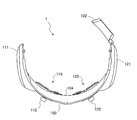
- FIG. 2 is a perspective view illustrating the appearance of the head-mounted device 1 as viewed from below and behind.
- FIG. 3 is a plan view of the head-mounted device 1 as viewed from above.
- FIG. 4 is a front view of the head-mounted device 1 as viewed from the front.
- the fixing member 101 illustrated in FIG. 2 is omitted.
- the lower rear refers to a position behind the user when the user wears the head mounting device 1 and a position where the user's head is looked up from below.
- the front means, for example, the front of the user (wearer) when the user wears the head mounting device 1.
- “above” means, for example, above the user.
- the portion of the head mounting device 1 that is located on the right side of the user wearing the head mounting device 1 is referred to as the right side portion or the right side.
- the part of the head mounting device 1 located on the left side toward the user wearing the head mounting device 1 is referred to as the left side portion or the left side.
- the surface of the head mounting apparatus 1 which contacts a user is called a back surface.
- the opposite side of the back side is called the front side.
- the surface is a surface that can be seen from the periphery of the user when the user wears the head-mounted device 1.
- the head mounting device 1 has a structure in which the head mounting device 1 is fixed to the user's head by tightening the fixing member 101 by winding the head mounting on the user's head. Therefore, the head mounting device 1 includes a belt-like base material 100 that is curved in a space slightly larger than a human head, and a fixing member 101 that is fixed to both ends of the base material 100.
- the fixing member 101 has wire rods 110 and 120 extending from both ends of the base material 100 and a fastener that pulls and fixes the wire rods 110 and 120 in pairs.
- the base material 100 forms an outer surface away from the user's head surface.
- the head mounting device 1 has a structure in which the base material 100 that is a member that maintains the shape is disposed on the outer surface away from the head.
- the base material 100 is made of, for example, a resin.
- the material of the base material 100 is not limited.
- the structure, shape, and material of the fixing member 101 are not limited.
- the fixing member 101 includes the wire rods 110 and 120, but a belt-like member may be used instead of the wire rod.
- the fastener may have any structure.
- a battery box 102 is provided at the right end of the base material 100 of the head-mounted device 1.
- the battery box 102 is a flat and substantially hexahedron, and both the area of the front surface and the area of the back surface are larger than the areas of the four side surfaces.
- a groove (not shown) is provided on the back surface of the battery box 102. An intermediate portion of the wire 120 extending from the right end portion of the substrate 100 is fitted in this groove. Therefore, the battery box 102 is fixed to the head mounting device 1 by being fixed at the right end portion of the substrate 100 and by fitting the wire 120 into the groove.
- Two rounded housings 111 and 121 are provided in the vicinity of both front side ends of the base material 100 of the head mounting device 1.
- the housings 111 and 121 accommodate a signal processing circuit, a control board having a communication circuit, and the like. As shown in FIG. 4, when the head mounting device 1 is viewed from the front, the two housings 111 and 121 appear to be located on both sides of the head mounting device 1.
- markers 113, 103, and 123 are arranged symmetrically with respect to the marker 103 and linearly at a position along the lower edge of the base material 100.
- the markers 113, 103, and 123 may have any structure as long as the positions of the markers 113, 103, and 123 can be identified on the image when captured by the imaging unit 28. However, it is desirable that the markers 113, 103, and 123 can recognize their areas on the image when taken by the imaging unit 28.
- the markers 113, 103, and 123 may be concave portions having circular or polygonal bottom surfaces provided on the base material 100.
- the markers 113, 103, and 123 may be convex portions having a circular or polygonal cross section provided on the base material 100.
- the markers 113, 103, and 123 may be formed on the base material 100 with a paint.
- the markers 113, 103, and 123 may be ones in which a paint is applied to the concave portion or the convex portion.
- strip-shaped openings 114 and 124 are formed above the markers 113 and 123, and knobs 112 and 122 are inserted into the openings 114 and 124, respectively.
- the knobs 112 and 122 are respectively connected to left and right sliders (not shown) provided along the back surface of the substrate 100.
- the sensors 115 and 125 are fixed to the slider on the back surface of the substrate 100. Therefore, by moving the knob 112 or the knob 122 relative to the base material 100 along the strip-shaped opening 114 or the opening 124, the sensor 115 or 125 can be moved on the back surface side. It is.
- a screw is formed coaxially with the knobs 112 and 122, and the position of the sensor can be fixed by a screw type.
- the knobs 112 and 122 and the markers 113, 103, and 123 are examples of means for positioning.
- the knob has a short cylindrical shape, but the shape of the knob is not limited.
- scales are engraved along the longitudinal direction of the strip-shaped opening 114 and the opening 124.
- the scale has a shape in which the scale at the center position and the scales other than the center position are different so that the center position can be understood.
- the scale at the center position has a triangular shape with the apexes facing the openings 114 and 124, while the scale other than the center position is formed in a circular shape or a dot shape.
- the method of forming the scale is the same as the method of forming the markers 113, 103, and 123, but there is no particular limitation.
- the sensors 115 and 125 have a shape in which three windows are provided on a flat plate.
- a near-infrared LED is provided as a near-infrared light source in one window portion of each of the sensors 115 and 125.
- a photodiode or a phototransistor is provided as a light receiving unit in the remaining two windows of each of the sensors 115 and 125.
- the number of light receiving portions of the sensors 115 and 125 is not limited to two.
- one light receiving unit may be provided for each of the sensors 115 and 125, or three or more light receiving units may be provided.
- the sensors 115-1, 115-2, 125-1 and 125-2 are called.
- the near-infrared light source and the light receiving unit are collectively referred to as sensors 115 and 125.
- light shielding portions 104 and 105 are provided on the upper and lower edges of the substrate 100. Therefore, the sensors 115 and 125 are installed in the space between the light shielding portions 104 and 105 at the upper and lower edges on the back surface of the base material 100. And the light-shielding parts 104 and 105 act also as a buffer material in the part which touches a forehead on the back surface of the head-mounted device 1. Although the material of the light-shielding parts 104 and 105 is not limited, a light and soft member is desirable to contact the user's head.
- the light shielding portions 104 and 105 are, for example, resin such as urethane, rubber, or the like.
- the base material 100 Furthermore, on the back surface of the base material 100, wiring for connecting the battery box 102, the sensors 115 and 125, and the substrates in the housings 111 and 121 is laid. However, the portion other than the portion where the sensors 115 and 125 are provided on the back surface of the base material 100 is covered with the cover 106.
- the cover 106 acts as a shielding plate that prevents the substrate, wiring, etc. from directly touching the user's skin on the back side of the head mounting device 1 that contacts the head side. Therefore, the wiring is laid in the space between the base material 100 and the cover 106.
- the CPU 21 of the user terminal 2 supports the alignment of the sensors 115 and 125 by the user in accordance with an alignment application program (hereinafter referred to as an alignment application) that is executed in the memory 22.
- the process in which the user terminal 2 supports the alignment of the sensors 115 and 125 by the user is also referred to as calibration.
- the user terminal 2 guides the user so that the sensors 115 and 125 are arranged at desired positions on the user's head.
- the sensors 115 and 125 detect a change in blood flow at a desired position on the user's head.
- the desired position of the user's head which is the calibration target, varies depending on the various services, functions, and applications used in this measurement system.
- the user terminal 2 provides various services or functions using measurement data transmitted from the head-mounted device 1 by executing an application program (hereinafter referred to as a brain application). Therefore, it is desirable to arrange the sensors 115 and 125 at the measurement site for each brain application before executing the brain application.
- the user terminal 2 captures a user's head image by the imaging unit 28 and displays it on the display unit 25.
- the user terminal 2 displays an object indicating the current position and the target position of the sensors 115 and 125, superimposed on the user's head image. Then, the user terminal 2 supports the user so that the current positions of the sensors 115 and 125 approach the target position.
- the user terminal 2 may be configured such that the feature points of the head-mounted device 1, such as the markers 103, 113, and 123, or the knobs 112 and 122, with respect to the head image of the user. The user may be guided so that the position is arranged at a desired position.
- the first calibration is a process that supports the work of positioning the sensors 115 and 125 at the target position of the user's head defined by the brain application when the user uses the brain application for the first time.
- the first calibration is a process of generating a reference image used in the second and subsequent calibrations.
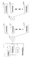
- FIG. 5 shows an example of the screen displayed by the user terminal 2 during the initial calibration.
- a head frame guideline, a cerebral blood flow measurement position guide frame, an eye position guideline, a nose, a center position guideline, and the like are displayed superimposed on the user's head image.
- the head frame guideline is, for example, a contour line surrounding an area of a predetermined size that simulates a human head. It is desirable that the size of the head frame guideline is a size that can be displayed on the display unit 25 and has a sufficient image size that does not hinder the positioning support by the user.
- the eye position guideline is, for example, a line segment that passes through the center of each of the left and right eyes.
- the nose and center position guidelines are, for example, vertical line segments that connect the center lines of the nose.
- the cerebral blood flow measurement position guide frame is a target position for positioning the sensors 115 and 125.
- the user terminal 2 first guides the user so that the head image of the user is in a desirable posture. For example, the user first adjusts the distance from the imaging unit 28 of the user terminal 2 to match the outline of his / her head with the head frame guidelines. Further, for example, the user corrects the head position so that his / her eyes, nose, and the like match the eye position guideline, the nose, and the center position guideline, respectively.
- the user terminal 2 displays a mark indicating the current position of the sensors 115 and 125 from the current shape and size of the head-mounted device 1 in the head image of the user and the positions of the knobs 112 and 122, etc. Display superimposed on the head image.
- the user adjusts the mounting state of the head mounting device 1 so that the current positions of the sensors 115 and 125 are superimposed on the target position indicated by the cerebral blood flow measurement position guide frame.
- the positions of the knobs 112 and 122 are instructed to the user by a message to the display unit 25 or the like so as to be set in advance to a predetermined knob position (default position) for each brain application executed by the user. May be.
- the alignment between the cerebral blood flow measurement position guide frame (target position) and the sensors 115 and 125 may be performed in a three-dimensional space. More specifically, the user terminal 2 determines the positions of the markers 103, 113, and 123 on the head-mounted device 1 mounted on the front surface of the head with reference to the arrangement of the characteristic parts such as eyes, nose, and mouth. Measure the coordinate system. The user terminal 2 not only has the positions of the marks 103, 113, and 123, but also the mark area, the width of the base material 100 (the height in the vertical direction), and the scales (gauge portion) of the openings 114 and 124 and the openings 114 and 124. The position information may also be used to measure the distance.
- L1 (S1) 1/2 / (S2) 1/2
- S1 the area of the measurement target in a certain position measurement L1
- L2 / L1 (S1) 1/2 / (S2) 1/2
- S1 the area of the measurement target in a certain position measurement L1
- S2 / L1 (S1) 1/2 / (S2) 1/2
- the user terminal 2 can obtain the distance L2 according to the above inversely proportional expression.
- the distance from the imaging unit 28 to the target markers 103, 113, 123, etc. may be calculated based on the areas of the markers 103, 113, 123, etc.
- the user terminal 2 is configured such that the three-dimensional of each part of the user's head is based on the horizontal line connecting the left and right eyes of the user, the center line of the face, the width of the face, the vertical length of the head What is necessary is just to specify a position coordinate.
- a plurality of three-dimensional models assuming a human head are prepared, and the dimensions such as the horizontal line connecting the left and right eyes of the user, the center line of the face, the width of the face, and the vertical length of the head are set.
- the three-dimensional coordinates of each part may be specified by selecting a suitable three-dimensional model.
- each part of the head-mounted device 1 and the three-dimensional coordinates of the user's head become coordinates defined in the same three-dimensional space by matching the origin.
- the midpoint of the line segment connecting the centers of the left and right eyes of the user may be used as the origin of the three-dimensional space.
- each part of the head-mounted device 1 may obtain three-dimensional coordinates with reference to the central marker 103, for example. Then, the user terminal 2 shifts the relative distance between the position of the center marker 103 and the midpoint of the line segment connecting the center of the left and right eyes of the user, so that the coordinate system of the user's head What is necessary is just to make the coordinate system of the head mounting apparatus 1 correspond.
- the target position of the user's head and the current position of the sensors 115 and 125 are the origin determined by the reference point of the user, such as the eyes, nose, mouth, head contour, etc. It is calculated with a three-dimensional coordinate system. Then, the target position of the three-dimensional coordinate system and the current positions of the sensors 115 and 125 are converted into a two-dimensional coordinate system and displayed superimposed on the image of the user's head.
- the user terminal 2 superimposes and displays the current positions of the sensors 115 and 125 of the head-mounted device 1 on the head image, and matches the cerebral blood flow measurement position guide frame.
- calibration is not limited to such processing.
- the characteristic points of the head-mounted device 1 for example, the upper and lower edges of the base material 100, the markers 103, 113, 123, the knobs 112, 122, etc. are positioned at the target position of the user's head image.
- the user terminal 2 may guide the user. That is, the position of the feature point of the head-mounted device 1 may be simply defined as the target position for each brain application on the user's head image (two-dimensional coordinates).
- the relative position in the openings 114 and 124 of the knobs 112 and 122 is instructed to the user in advance to be a predetermined knob position (default position) for each brain application executed by the user. Just keep it. Then, the user moves and adjusts the feature point of the head-mounted device 1 to the target position displayed on the user terminal 2 so as not to move the relative position of the knobs 112 and 122 in the openings 114 and 124. That's fine.
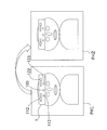
- FIG. 6 illustrates the second and subsequent calibration processes.
- a head image (referred to as a reference image) of a user wearing the head mounting device 1 at a desired arrangement position obtained by the initial calibration is stored in the memory 22 (nonvolatile) of the user terminal 2.
- Storage device Therefore, the user terminal 2 arranges the reference image (PH1) on the display unit 25 and superimposes and displays the current head image (PH2) of the user.
- the user first adjusts the dimensions of the reference image (PH1) and the current head image (PH2) by adjusting the distance from the imaging unit 28 of the user terminal 2.
- the state and posture of the head are corrected so that the head in the reference image (PH1) matches the head in the current head image (PH2).
- the posture or the like of the current head image (PH2) may be corrected such that the eyes, nose, mouth, contour, etc. of the current head image (PH2) are superimposed on the reference image (PH1).
- the user may correct the mounting state of the head mounting device 1 so that the arrangement of the head mounting device 1 in the current head image (PH2) matches the reference image (PH1).
- the markers 103, 113, 123, the knobs 112, 122, etc. of the current head image (PH2) may be adjusted so as to overlap with the respective portions of the reference image (PH1).
- the user terminal 2 executes the alignment application. After executing the matching application, the user terminal 2 executes the brain application, and provides a service to the user or the user based on the change in the blood flow at the user's brain measurement target site. Provide various information.
- Examples of services or functions provided by the above measurement system include the following.
- the user terminal 2 may provide a service or a function to the user by itself, by the user terminal 2 executing the brain application.
- a program such as a brain application or a browser of the user terminal 2 may access the trader server 3 via the network N2, and the trader server 3 may provide services or functions to the user terminal 2.
- Provision of information related to the activity state of the user's brain to the user For example, the user terminal 2 or the trader server 3 (hereinafter referred to as the user terminal 2 or the like) receives information indicating the activity state of the brain. It can be presented to the user as a graph, table, etc.
- the image includes a change in screen color and a change in brightness (luminance).
- the user terminal 2 or the like can be used for sound, sound, vibration, and the like based on the measured brain activity state.
- a physical effect including at least one of the light may be provided to the user.
- the physical effect is, for example, providing music, music, or the like that matches the activity state of the user's brain, controlling vibration in the massage device, controlling room lighting, and the like.
- the user terminal 2 or the like is a participant involved in the user's current activities, for example, Information related to the activity state of the user's brain may be provided to school, cram school, sports club instructors, teachers, instructors, coaches, etc. using the graphs, tables, images, and the like. Schools, private schools, and sports clubs can provide guidance according to the brain activity status of users.
- (E) control of equipment personal computer, tablet computer, vehicle-mounted device, etc.
- a personal computer equipped with a learning application a device such as an in-vehicle device, or a facility such as a school, a cram school, or a sports club May provide the user with a stimulus that activates the user's brain.
- a stimulus is a stimulus by display on the display, sound, sound, physical vibration, light, or the like.
- the in-vehicle device determines that the user's brain is in an inactive state from the blood flow change measurement data of the head-mounted device 1, a physical stimulus (display or the like) for preventing drowsiness. Visual stimuli, audio stimuli such as sound and sound) may be given to the driver. Further, the vehicle-mounted device may guide the driver to take a break by determining the measurement data of the blood flow change.
- a computer of a facility such as a school, a cram school, or a sports club determines from the measurement data of the blood flow change of the head-mounted device 1 that the brain of the user who is a participant is inactive.
- information for identifying a participant whose brain is inactive or a brain state of each participant may be displayed on the display so as to give a stimulus of being seen by each participant.
- These computers may acquire blood flow change data measured by the head-mounted device 1 via the user terminal 2, or the head-mounted device via the network N1 illustrated in FIG. Data on the change in blood flow may be acquired directly from 1.
- the user terminal 2 is the activity state of the user's brain May be transmitted to other equipment such as a smartphone, a PC, or a television broadcasting station.
- a computer of a television broadcasting station obtains a measurement value indicating an activity state of a viewer's brain in association with a broadcast program, advertisement, etc., and shows a viewer's sensitivity to the program, a brain activity indicating a reaction to the advertisement. Can be output based on a change in blood flow at the brain function site.
- the advertisement may be a moving image or a still image.
- Information related to the activity state of the user's brain The user terminal 2 or the trader server 3 is based on the measurement data of the change in blood flow in the head measured by the head-mounted device 1. Information on the brain activity state is provided in various forms or modes to the user or a business provider that provides services to the user.
- the user terminal 2 or the trader server 3 may provide information indicating the current situation by comparing the evaluation value accumulated in the past with respect to the activity state of the user's brain and the current evaluation value. Further, the user terminal 2 or the trader server 3 may provide information indicating a correlation between an evaluation value for the activity state of the user's brain and other human body information of the user. Further, the user terminal 2 or the trader server 3 may provide information indicating the correlation between the evaluation value about the activity state of the user's brain and the physical condition of the user. Further, the user terminal 2 or the trader server 3 may provide information indicating a correlation between the evaluation value about the activity state of the user's brain and the mental state of the user.
- the user terminal 2 or the trader server 3 may provide a correlation between an evaluation value about the activity state of the user's brain and information provided on the Internet.
- H Application to feedback training Since athletes place importance on self-control, they perform heartbeat feedback training. For example, in the United States, feedback training using brain waves is also conducted. A user wears the head-mounted device 1, executes a brain application on the user terminal 2, and can perform feedback training using measurement data of changes in the blood flow of the user himself / herself.
- Example 1 the measurement system of Example 1 will be described with reference to FIGS.
- the system configuration of the measurement system of Example 1 and the structure of the head mounting device 1 are the same as those illustrated in FIGS. 1 and 2-4.
- a processing example in which the user terminal 2 executes calibration for each brain application based on the user's head image captured by the imaging unit 28 will be described.
- FIG. 7 is a diagram illustrating the model coordinate system of the user in the first embodiment.
- the user terminal 2 according to the first embodiment sets the X axis on a straight line connecting the left and right eyes on the user's head image captured by the imaging unit 28. For the direction, the right direction toward the user is defined as the positive direction.
- the user terminal 2 sets the Y axis with the upward direction being positive on a straight line passing vertically through the center of the user's nose.
- the user terminal 2 sets the Z-axis at the origin, with the upper direction perpendicular to the paper surface of FIG. As described above, the user terminal 2 sets the three-dimensional coordinate system of the human head.
- the user terminal 2 has a model in which the actual size of the user's head is changed to a standard size.
- the standard size is defined by, for example, the width of the face, and a typical human size may be used.
- the user terminal 2 has the arrangement positions of the sensors 115 and 125 corresponding to the respective brain applications on the standard size model as data of the three-dimensional coordinate system. Therefore, the user terminal 2 converts the head image obtained by capturing the user's head with the imaging unit 28 into a standard size model and mounts the head mounting device 1 in a two-dimensional coordinate system on the head image. The position is converted into the mounting position in the 3D coordinate system of the standard size model.
- the user terminal 2 serves as a guide to the head image displayed in the two-dimensional coordinate system on the display unit 25 so that the sensors 115 and 125 are arranged at target positions for each brain application in a standard size model.
- the object is displayed, and the user supports the alignment of the sensors 115 and 125.
- FIG. 8 is an example of a measurement position management table in which a relationship between a measurement target region and a target position where the sensors 115 and 125 are arranged in the model is defined in a standard size three-dimensional model.
- a human brain is divided into a plurality of regions, and a target position where the sensors 115 and 125 are arranged is defined in order to accurately measure a change in blood flow in each divided region.
- the measurement position management table in FIG. 8 is held in the memory 22 of the user terminal 2.
- the first line is an explanation line
- what is actually held in the memory 22 is the second and subsequent lines of the table of FIG.
- FIGS. 9 and 10 the same applies to FIGS. 9 and 10 in that the first row of the table is not the data actually held in the memory 22 but an explanatory row.
- the No element is information for identifying a row in the measurement position management table.
- the element No may be omitted in the measurement position management table. This is because each row of the measurement position management table can be identified by the name of the measurement part.
- the element of the measurement part name is information for specifying a measurement target part of the human brain.
- Various classification methods have been proposed for classification of the human brain. For example, there is a method of classifying the cerebrum, diencephalon, cerebellum, brain stem, etc. according to the structure of the brain, and further classifying the cerebrum into frontal lobe, parietal lobe, occipital lobe, temporal lobe and the like.
- Corbinian Broadman proposed a brain map by assigning numbers from 1 to 52 by dividing the parts of the cerebral cortex that are uniform in structure into one group. In Example 1, like the Broadman's brain map, each part of the cerebral cortex is numbered and used as a measurement site name. In FIG.
- the measurement site names are exemplified by 1 field,. That is, in this measurement system, when the cerebral cortex is divided and measured, the classification is not limited to the same classification as the Broadman brain map.
- This measurement system uses the standard brain map equivalent to Broadman's brain map, the brain map uniquely defined by the manufacturer, the brain classification with standard brain coordinates, etc. What is necessary is just to measure the change of the blood flow volume of each division suitable for application.
- the table of FIG. 8 is 9 fields, 10 fields, 11 fields, 45 fields, 46 fields. , 47-row table configuration.
- the offset coordinate (x), the offset coordinate (y), and the offset coordinate (z) are target positions at which the sensors 115 and 125 are arranged to measure each part identified by the measurement part name, and are in a three-dimensional coordinate system. Is the coordinate value.
- the three-dimensional coordinate system is the coordinate system illustrated in FIG.
- the position of each part is the position in the standard size model illustrated in FIG.
- the measurement range (r) is an allowable error from the target position, for example, a radius from the offset coordinate (x), the offset coordinate (y), and the offset coordinate (z).
- the user terminal 2 detects the sensors 115 and 125 at the target position of the standard size model in the three-dimensional coordinate system. Place. And the user terminal 2 calculates
- FIG. 9 is an example of the structure management table of the head-mounted device 1 (illustrated as a headset in FIG. 9).
- the structure management table defines the size or position of each part of the head-mounted device 1.
- the head-mounted device 1 is not in a curved state but has a size and a position in a state where the head-mounted device 1 is extended on a plane.
- positions of the headset horizontally long, the headset vertically long, markers L1, M1, R1, sliders L1, L2, sensor slider movable ranges L1, R1, sensors L11, L12, R11, R12, etc. are illustrated.
- the structure management table is not limited to the definition of each part in FIG.
- the markers L1, M1, and R1 correspond to the markers 113, 103, and 123 in FIG. 4, respectively.
- Sliders L1 and L2 correspond to the knobs 112 and 122, respectively.
- the sensors L11 and L12 correspond to the two light receiving units of the sensor 115
- the sensors R11 and R12 correspond to the two light receiving units of the sensor 125.
- a total of four sensors are defined.
- the number of sensors is not limited to four.
- Each line in FIG. 9 has elements of size, offset coordinate (x), offset coordinate (y), offset coordinate (z), and movable range.
- the size element holds the dimensions of each part.
- the offset coordinate (x), the offset coordinate (y), and the offset coordinate (z) are position coordinates at which each part reference point of the head-mounted device 1 is arranged.
- the offset coordinates are, for example, coordinates in the coordinate system in the head-mounted device 1 with the marker M1 as the origin.
- the coordinate system in the head-mounted device 1 is, for example, an X-axis that passes through the markers L1, M1, and R1 and is positive in the right direction toward the user wearing the head-mounted device 1, and a marker M1 (origin).
- the movable range is an element set for the sensor slider movable ranges L1 and R1.
- the user terminal 2 Since the user terminal 2 has the structure management table in the memory 22, for example, the shape of the head-mounted device 1 obtained from the user's head image (for example, the ratio of the headset horizontal to vertical), the component Based on the arrangement (the positions of the markers 113 and 123 with respect to the marker 103), the area of the component, and the like, the degree of curvature of the head-mounted device 1 and the distance from the head-mounted device 1 to the imaging unit 28 can be recognized. That is, the user terminal 2 calculates the positions of the sensors 115 and 125 in the three-dimensional coordinate system based on the size and offset position of the structure management table and the area and position of each part on the image. Then, as illustrated in FIG.
- the user terminal 2 uses the sensors 115 and 125 to detect the origin of the head image obtained from the feature points (eyes, nose, etc.) of the head image of the user. Find the current position. Then, the user terminal 2 converts the current position in the three-dimensional coordinate system obtained from the image into the position of the standard size model. Therefore, the user terminal 2 can obtain the current positions of the sensors 115 and 125 in the standard size model. Further, the user terminal 2 obtains the target positions of the sensors 115 and 125 in the standard size model. Further, the user terminal 2 converts the current positions and target positions of the sensors 115 and 125 into positions on the image of the two-dimensional coordinate system captured by the imaging unit 28. In this way, the user terminal 2 displays the current position of the sensors 115 and 125 and the target position where the sensors 115 and 125 are arranged on the user's head image captured by the imaging unit 28, and Can guide.
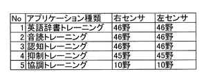
- FIG. 10 is an example of a sensor slider setting value management table.
- the sensor slider set value management table defines a measurement site for each type of application (brain application). As already described with reference to FIG. 8, the arrangement positions of the sensors for measuring each measurement site are set in the measurement position management table. Therefore, when the brain application to be executed is determined, the user terminal 2 searches for the corresponding brain application from the sensor slider setting value management table, and reads the measurement site designated by each sensor. Then, the user terminal 2 reads out an arrangement position of a sensor for measuring each measurement site from the measurement position management table, and an object (guide) serving as a target position for arranging the sensor at the corresponding position on the user's head image. (Also called).
- Each row of the sensor slider setting value management table in FIG. 10 has elements of application type, right sensor, and left sensor.
- the name of the brain application executed by the user terminal 2, or the identification information of the brain application, the identification code, and the like are designated.
- English dictionary training, reading aloud training, cognitive training, suppression training, cooperative training, and the like are illustrated as brain applications. Of these, cognitive training is also called brain training.
- the cooperative training is training that strengthens teamwork, for example.
- the right sensor and the left sensor are information for identifying each sensor, and the measurement target portion of each sensor is designated as the corresponding element in each row.
- the brain region is a standard brain map equivalent to the Broadman brain map, or a brain map uniquely defined by the manufacturer, or standard brain coordinates. It may be defined by using the brain classification.
- the head-mounted device 1 has knobs 112 and 122, the sensor 115 can be slid by the knob 112, and the sensor 215 can be slid by the knob 122.
- the sensor 115 corresponds to a left sensor.
- the sensor 125 corresponds to the right sensor. Therefore, the left sensor can be moved by the knob 112, and the right sensor can be moved by the knob 122.
- FIG. 11 shows an example of data stored in the memory 22 by the user terminal 2.
- each data is exemplified by an area name in the memory 22.
- the input image memory refers to a buffer area in the memory 22 in which data captured by the imaging unit 28 is held. Images are written in the input image memory, which is a buffer area, from the imaging unit 28 at a predetermined frame interval (cycle).
- the face image memory holds image data of the user's face recognized by the user terminal 2 (matching application) among the image data of the user's head written in the input image memory.
- the eye image memory, the nose image memory, and the mouth image memory are the user's eyes, nose, and mouth recognized by the user terminal 2 (matching application) among the image data of the head of the user written in the input image memory.
- the image data of each part is held.
- the headset image memory and the marker image memory are the image data of the head-mounted device 1 recognized by the user terminal 2 (matching application) among the image data of the user's head written in the input image memory, Holds the marker image data.
- the sensor image memory holds mark image data indicating a target position where the sensor is to be arranged.
- the eye 2D coordinate memory holds coordinate values of a two-dimensional coordinate system indicating the position of the eye in the head image recognized by the user terminal 2.
- the midpoint of the line segment connecting the center points of the left and right eyes of the user is set as the origin (see the X and Y axes in FIG. 7).
- the headset 2D coordinate memory holds coordinate values indicating the position of the reference point of the current head-mounted device 1 in the two-dimensional coordinate system.
- the marker 2D coordinate memory and the sensor 2D memory hold coordinate values of a two-dimensional coordinate system indicating the positions of the marker and the sensor, respectively.
- the eye position memory, the nose position memory, the mouth position memory, the headset position memory, the marker position memory, and the sensor position memory are the three-dimensional coordinate system of the eyes, nose, mouth, reference point of the head-mounted device 1, the marker, and the sensor, respectively. Holds the coordinate value at.
- FIG. 12 is a flowchart illustrating the initial alignment processing procedure.
- the CPU 21 executes the process of FIG. 12 according to the matching application that is a computer program on the memory 22.
- the CPU 21 executes the process of FIG. 12 before executing the brain application.
- the CPU 21 executes a process as an image input unit, and acquires an image photographed by the imaging unit 28 (S1). And CPU21 performs a process as an image process part (S2). In the process of S2, the CPU 21 recognizes feature points in the user's head image from the image acquired in S1, for example. Next, CPU21 performs a process as a position calculation part (S3). In the process of S3, the CPU 21 calculates the coordinate value of each feature point recognized in S2, for example.
- the CPU 21 executes processing as a sensor attachment position data management unit (S4).
- the CPU 21 acquires the size, offset position (x, y, z), movable range, and the like of each part of the head mounting device 1 from the structure management table of the head mounting device 1 illustrated in FIG. .
- CPU21 performs a process as a sensor position determination part (S5).
- the CPU 21 calculates the current position (three-dimensional coordinate system) of the sensor from the size of each part of the head-mounted device 1, the offset position (x, y, z), and the position of the feature point in S2. .
- CPU21 acquires the measurement site
- the CPU 21 acquires the offset position of the sensor corresponding to the measurement site of each sensor from the measurement position management table illustrated in FIG. Then, the offset position of the sensor is arranged on a model obtained by converting the size of the user's head into a standard size in the three-dimensional space.
- This offset position is a target position where the sensor is arranged corresponding to the brain application.
- the CPU 21 converts the model image in which the current position and target position of the sensor are arranged into two dimensions.
- the two-dimensional image is a coordinate system in which the midpoint of the line segment connecting the midpoints of the left and right eyes of the user is the origin.
- the CPU 21 converts the size of the model head from the standard size to the size of the user's head, and obtains the current position and target position of the sensor in the two-dimensional coordinate system. . Then, the CPU 21 draws an object serving as a guide at the current position and the target position of the sensor in the two-dimensional coordinate system.
- the CPU 21 executes processing as an image composition unit (S6).
- the CPU 21 superimposes the two-dimensional image generated by disposing the sensor on the model in the process of S5 on the user's head image acquired from the imaging unit 21.
- the CPU 21 determines whether or not the alignment has been sufficiently performed (S7).
- the case where the alignment is sufficiently performed means, for example, a case where, in a standard size model, the position of the sensor is within the allowable error range in the measurement part defined for each application. If the determination in S7 is negative, the CPU 21 prompts the user to correct the current position of the sensor closer to the target position, and the process as the image input unit in S8 and the process as the sensor position determination unit in S5. Execute. That is, the CPU 21 obtains the user's head image again from the imaging unit 28 and draws an object serving as a guide at the current position and target position of the sensor in the two-dimensional coordinate system. This is an example of means for assisting the adjustment by the positioning means by the CPU 21 that executes S1 to S8.
- the CPU 21 executes a process as a position information storage unit (S9).
- the CPU 21 stores, for example, the current positions of the eyes, nose, etc., the positions of the markers 103, 113, 123, and the like in the memory 22.
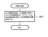
- the CPU 21 executes processing as an image information storage unit (SA).
- SA image information storage unit
- the CPU 21 stores the two-dimensional image synthesized in S6 in the memory 22 as a reference image.
- the CPU 21 executes processing as an output unit, and outputs information indicating that the alignment is successful.
- the CPU 21 executes any one of a message output to the display unit 25, an output to the output unit 27 such as sound or vibration, or a combination thereof (SB).
- FIG. 13 is a flowchart illustrating the details of the processing of the image processing unit (S2 in FIG. 12).
- the CPU 21 executes a process as an image reading unit (S21).
- the CPU 21 acquires an image held in a frame buffer or the like.
- the CPU 21 stores the acquired image in, for example, an image memory in the memory 22.
- the CPU 21 executes processing as face detection means (S22). In this process, the CPU 21 identifies a face portion from the image. For example, the CPU 21 stores the acquired face image in a face image memory in the memory 22. Next, the CPU 21 executes processing as eye detection means (S23). In this process, the CPU 21 identifies the eye portion from the image. The CPU 21 stores the acquired image of the eye portion in, for example, an image memory in the memory 22. Next, CPU21 performs a process as a nose detection means (S24). In this process, the CPU 21 identifies the nose portion from the image. The CPU 21 stores the acquired image of the nose portion in, for example, an image memory in the memory 22. Next, CPU21 performs a process as a mouth detection means (S25).
- the CPU 21 identifies the mouth portion from the image.
- the CPU 21 stores the acquired mouth image in, for example, an image memory in the memory 22.
- the processing from S22 to S25 is the same as the detection of the face, eyes, nose, and mouth during the face recognition processing performed by, for example, a general digital camera.
- the CPU 21 executes processing as a headset detection unit (S26).
- CPU21 should just perform template matching with the image acquired by S21, for example using the template image of the head mounting apparatus 1 (headset).
- the CPU 21 stores the acquired image of the head-mounted device 1 in, for example, a headset image memory in the memory 22.
- CPU21 performs a process as a marker detection means (S27).
- S27 is the same as S26.
- the CPU 21 stores the acquired image including the markers 103, 113, and 123 in the marker image memory in the memory 22, for example.
- the CPU 21 executes processing as a sensor detection means (S28).
- S28 the CPU 21 determines from the position and dimensions of the markers 103, 113, and 123 of the head-mounted device 1, the dimensions in the image of the equipment 100, and the positions of the knobs 112 and 122, and the back side of the head-mounted device 1.
- the current positions of the sensors 115 and 125 are calculated. As already described, the current positions of the sensors 115 and 125 are obtained in a three-dimensional coordinate system, for example, converted into the position of the standard model. However, in the process of S28, the current positions of the sensors 115 and 125 are obtained in the coordinate system of the head-mounted device 1 (the origin is the marker M1 (marker 103)). This is because the positions of the feature points such as the user's face, eyes, and nose have not yet been obtained.
- FIG. 14 is a flowchart illustrating the details of the processing of the position calculation unit (S3 in FIG. 12).
- the CPU 21 extracts the marker coordinate information and the number of pixels of the marker from the marker image memory, and defines the structure of the head mounted device 1 (in the electronic file in which the physical size and the arrangement relationship are defined).
- the head-mounted device 1 On the head-mounted device 1 corresponding to one pixel of the marker image, based on information on the physical size of the marker in the drawing or the parameter group that defines the dimensions of each part, or the physical size of the marker in the drawing and the parameter group)
- the actual size of the marker (mm / pixcel) and the curvature are obtained, and the actual position of the marker in the three-dimensional coordinate system is calculated from the secondary coordinate system on the image (S31).
- the CPU 21 stores the markers 103, 113, and 123 acquired from the marker images in the memory 22.
- the relative distance is calculated by comparing the size (especially the size of the central marker 103) and the size of three known markers (particularly the size of the central marker) of the head-mounted device 1.
- the CPU 21 stores the known arrangement information of the markers provided on the left and right of the headset structure diagram and the marker images in the memory 22 (in particular, the markers 113 and 123 provided on the left and right of the head-mounted device 1).
- the CPU 21 can calculate the actual positions of the markers 103, 113, and 123 in the three-dimensional coordinate system.
- the CPU 21 calculates the eye position with respect to the marker coordinate, the eye coordinate in the two-dimensional coordinate system of the image, and the marker position in the three-dimensional coordinate system (S32).
- the position of the eye is positioned below the position of the central marker 103 in the structure of the head-mounted device 1.
- the CPU 21 determines between the position of the head-mounted device 1 (the positions of the markers 103, 113, and 123) and the eye height (the position in the Y-axis direction of the line segment that connects the centers of the left and right eyes). And the information in the memory 22 having statistical data on the distance between the eyes and the distance between the eyes (the length of the line connecting the centers of the left and right eyes, the length between the corners of the eyes, the length between the eyes)
- the eye position may be calculated from the marker coordinates.
- the CPU 21 may specify the position of the eye in the image by pattern matching using a database of eye image patterns provided in the memory 22.
- a database of eye image patterns provided in the memory 22.
- the actual eye position may be specified from the curvature derived above.
- Such a correspondence relationship may be held in a database table held in the memory 22.
- the CPU 21 may be configured to calculate the functional relationship by holding such a correspondence relationship in the memory 22 with parameters of an empirical formula.
- the CPU 21 calculates the marker coordinates, nose coordinates in the two-dimensional coordinate system of the image, and the nose position relative to the marker position in the three-dimensional coordinate system (S33). Similarly to the specification of the eye coordinates, the nose position can also be specified using statistical data or nose pattern matching. Next, the CPU 21 calculates the marker coordinates, the mouth coordinates in the two-dimensional coordinate system of the image, and the mouth position with respect to the marker position in the three-dimensional coordinate system (S34). The mouth position can be specified in the same manner as the eye and nose positions. Next, the CPU 21 calculates the sensor slider position from the marker coordinates in the two-dimensional coordinate system of the image, the sensor slider coordinates, and the marker position in the three-dimensional coordinate system (S35). The sensor slider position is the same as above. The sensor slider position is the position of the knobs 112 and 122 illustrated in FIG. Finally, the CPU 21 calculates the sensor position from the sensor slider position and the sensor movable range of the headset structure management table as described above.
- FIG. 15 is a flowchart illustrating the details of the processing of the image composition unit (S6 in FIG. 12).
- the CPU 21 acquires an input image, copies it to an output image, and presents current sensor position information (current position sensor object) and cerebral blood flow measurement sensor position information for each application (target position object). Are superimposed and displayed (S61).
- FIG. 16 is a configuration diagram illustrating the second calibration process executed when the user uses a brain application that has been used for a second time.
- sensors are already aligned when the brain application is executed for the first time.
- the sensor alignment result by the calibration at the time of executing the first brain application is the initial adjustment information storage area of the memory 22 as a photographed image at the time of initial adjustment in a state where the head mounting device 1 is mounted on the user's head. Is saved.
- the image of the user wearing the head-mounted device 1 for the second time or later is acquired in the head-mounted position information storage area, for example, at a predetermined frame interval (cycle).
- the user terminal 2 does not have to execute the processes illustrated in FIGS. 12 to 15 again as in the first use.
- the user terminal 2 may guide the user to take the same mounting state of the head-mounted device 1 as that of the first adjustment photographed image at the same distance from the imaging unit 28 as the first time. This guide is implemented by the user terminal 2 according to the head mounting position adjustment application (alignment application).
- the user terminal 2 displays the current user's head image on the display unit 25 and displays the first adjustment-time captured image in a superimposed manner. Then, the user terminal 2 informs the user of the distance from the imaging unit 28, the posture of the user, the head mounting device, so that the current user's head image is the image of the first adjustment photographed image. It is only necessary to prompt the user to correct the mounting state of 1 and the positions of the knobs 112 and 122.
- FIG. 17 is a flowchart illustrating the second and subsequent calibration processes.
- the user terminal 2 executes the brain application, the user terminal 2 confirms whether or not the first adjustment-time captured image corresponding to the brain application is stored, thereby performing the second and subsequent calibrations. Whether or not to execute can be determined. If the user terminal 2 determines that the calibration is for the second time or later, the user terminal 2 activates the processing of FIG. In this process, for example, the user terminal 2 instructs the user to wear the head-mounted device 1 (S71). Then, the CPU 21 of the user terminal 2 starts a headset wearing position adjustment application (alignment application) (S72). The following processing is processing of the CPU 21 by the head mounting position adjustment application. In this process, the user turns the imaging unit 28 of the user terminal 2 toward himself / herself. Thereby, the imaging part 28 image
- the CPU 21 acquires the first adjustment photographed image from the storage area (memory 22) (S74).
- the first adjustment image is an example of the stored head image.
- the CPU 21 that executes the process of S74 is an example of a unit that acquires a saved head image of the user.
- the CPU 21 acquires the current user's own image (hereinafter referred to as “camera image”) captured by the imaging unit 28 from the frame buffer (S75).
- a camera image is an example of a user's current head image.
- the CPU 21 that executes the process of S75 is an example of a unit that acquires the current head image of the user.
- the CPU 21 displays the camera image and the first adjustment photographed image on the display unit 25 (S76).
- the CPU 21 extracts a difference image between the camera image and the first adjustment photographed image (S77). Then, the CPU 21 calculates the difference image area size and determines whether or not the difference image area size is within a threshold value (S78).
- the difference image area size is, for example, the area of the difference image or the longest dimension of the image. For example, the CPU 21 can calculate the area of the difference image by integrating the number of pixels in the difference image. For example, the CPU 21 may obtain the longest dimension of the image by counting the number of pixels where the pixels are continuous in the difference image.
- the threshold value can be set as a system parameter of the user terminal 2 from an experimental value and an experience value.
- the CPU 21 instructs the user to adjust the mounting position (S79).
- the instruction in S79 is based on, for example, a message to the display unit 25, sound, voice from the output unit 27, vibration, or the like. Then, the CPU 21 returns the control to S77.
- the camera image is updated at a predetermined frame interval (cycle). This is an example of means for supporting the adjustment by the positioning means by the CPU 21 that executes the processes of S76 to S79.
- the CPU 21 records the headset mounting position information in the headset position information storage area (S80). Then, the CPU 21 instructs each unit to complete calibration (S81).
- the instruction to each unit is, for example, an output to the display unit 25, the output unit 27, etc., a brain application execution instruction, or the like.
- the user terminal 2 that has received the transfer of detection data that detects a change in blood flow in the user's head can provide various services to the user. .
- the current position of the sensors 115, 125, etc. with respect to a coordinate system in which the user terminal 2 is defined by the markers 103, 113, 123, the dimensions of the base material 100, the user's eyes, nose and other characteristic points.
- the guide using the object at the target position is performed to assist the positioning by the user. Therefore, the user can adjust his / her posture, head position, distance from the imaging unit 28 to his / her head, the mounting position of the head mounting device 1 on his / her head, and the like according to the guide. Further, the user can finely adjust the positions of the sensors 115 and 125 to specific parts of the user's head by using the knobs 112 and 122.
- this measurement system is related to the user's inner reaction or reaction, such as language, action, perception, memory, attention, judgment, especially thinking, creation, intention, planning.
- Measurement data to be acquired can be acquired, and a service corresponding to the reaction or state of the user's inner surface can be provided to the user himself / herself, or to a business operator who uses the reaction or state of the user's inner surface.
- the measurement data can be easily used for various services and applications.
- the above positioning support is made for the appropriate specific part set for each service provided to the user and each application program used by the user, it matches the internal reaction or state of the user. Service and application program functions can be provided.
- the alignment application guides the user so that the sensor is positioned with respect to an appropriate specific part using an image obtained by photographing the user, the user is desirable according to the purpose of use. It becomes easy to position the part more accurately.
- the user terminal 2 calculates the distance between the user's head and the imaging unit 28 based on the dimensions of each part of the head-mounted device 1, and the imaging unit 28.
- the conversion from the two-dimensional coordinate system obtained in step 3 to the three-dimensional coordinate system is performed. Therefore, the user terminal 2 can convert the image of the imaging unit 28 into the three-dimensional coordinate system with high accuracy.
- the user terminal 2 has a sensor arrangement position on a standard size model. Then, the user terminal 2 uses the current position of the sensor based on the image of the two-dimensional coordinate system obtained by the imaging unit 28 and the target for each brain application specified by the sensor slider setting value management table illustrated in FIG. The position is once obtained and converted into a two-dimensional coordinate system image obtained by the imaging unit 28, and the current sensor position and target position objects are displayed. Therefore, the user terminal 2 can guide the user with high accuracy.
- the user terminal 2 guides the user by superimposing the current head image on the head image at the time of sensor positioning that has been performed in the past. Therefore, the user can perform the positioning of the current sensor with the goal of an appropriate positioning state that has a track record in the past, and the adjustment by the user becomes easy.
- ⁇ Modification> conversion from the two-dimensional coordinate system obtained by the imaging unit 28 to the three-dimensional coordinate system is performed, and the current position and the target position of the sensor are obtained using a standard size model.
- the present measurement system is not limited to such processing.
- the two-dimensional coordinate system (XY coordinate system) obtained by the imaging unit 28 the user's head image and the model may be aligned.
- the measurement position for each brain application may be converted from the measurement position in the three-dimensional coordinates of the model cerebral cortex to the two-dimensional coordinate system on the screen.
- Such alignment on the image of the two-dimensional coordinate system may be less accurate than the case of the first embodiment, but the processing in the user terminal 2 is simplified.
- the head-mounted device 1 illustrated in the first embodiment is connected to a plurality of user terminals 2-1, 2-2, 2-N, etc. via the network N1.
- Example 2 except that user terminals 2-1, 2-2, 2-N etc. are connected to the same head-mounted device 1 via the network N1 at the same timing or during the same period.
- the components and operations are the same as those in the first embodiment.
- any one of the user terminals 2-1 to 2-N is further connected to a plurality of user terminals 2-N1, 2-N2, 2-NK, etc. via the network N2.
- the network N1 is, for example, a network to which the wireless communication unit 13 is connected, as in FIG.
- the network N2 is, for example, a public line network as in FIG.
- the user terminals 2-1, 2-2, 2 -NK, etc. are not necessarily the same type of computer.
- the user terminals 2-1, 2-2, 2 -NK, etc. are collectively referred to as the user terminal 2.
- a user wearing the head-mounted device 1 is referred to as a subject.
- responses to the subject's products, services, etc. are transferred to the user terminals 2-1, 2-2, 2-NK of a plurality of members.
- Responses to these products and services include responses when the subject operates personal devices, responses when the subject looks at fashion products and designs, responses when the subject eats and drinks food, drinks, etc. Reaction when using a health device, massage device, etc., reaction when the subject is given medicine, response when the subject watches a television program, music, advertisement, movie, theater, etc.
- reaction when reading when reading, reaction when the subject plays an electronic device game, response when the subject uses an attraction at a theme park, game center, etc., when the subject uses a pachinko, pachislot, etc.
- Examples include reactions and responses when a subject performs a specific exercise, takes a specific action, or performs a specific task.
- the head mounted devices 1 respectively mounted on a plurality of subjects are connected to the user terminals 2-1, 2-2, and the like via the networks N1, N2, etc. It may be connected to 2-NK or the like.
- a plurality of users such as user terminals 2-1, 2-2, 2-N may want to obtain responses from a plurality of subjects at the same timing and the same period.
- a plurality of head mounted devices 1-1, 1-2, 1 -N having the same configuration as the head mounted device 1 illustrated in the first embodiment are connected to the user terminal 2-via the network N 1. 1 is connected.
- the components and operations of the third embodiment are the same as those of the third embodiment except that a plurality of head-mounted devices 1-1, 1-2, 1-N, etc. are connected to the user terminal 2 via the network N1. Same as 1.
- the measurement system according to the third embodiment may be configured such that the user terminal 2-1 is further connected to the user terminal 2-2 via the network N2.
- the networks N1 and N2 are the same as those in the first and second embodiments.
- the head-mounted devices 1-1, 1-2, 1-N, etc. are collectively referred to as the head-mounted device 1.
- a measurement system configured as shown in FIG. 19, that is, an environment for collecting blood flow change measurement data from a plurality of subjects, for example, a reaction when a product, service, etc. are provided to a plurality of people is used as a user terminal. Some are transferred to 2-1, 2-2, etc.
- Responses to these products and services include, for example, the responses or effects of subjects at various schools, cram schools, seminars, etc., responses or effects when subjects perform specific tasks, services at fitness clubs, etc. Examples include responses of a plurality of subjects at an event venue, such as responses to exercise, etc., responses of subjects when providing services through mass media such as television broadcasting and the Internet.
- the head mounting device 1 by mounting the head mounting device 1 on a public transport, airplane, ship, train, or bus driver, crew, pilot, steering, etc., the public transport, airplane, ship, train You can monitor changes in the operator's physical condition and brain blood flow.
- the head mounting device 1 by mounting the head mounting device 1 on a taxi driver or a truck driver, changes in the physical condition and blood flow of the brain can be monitored.
- the measurement system for example, in a collaborative work training (team creation) by a plurality of people, the effect of the training, whether the activity is flourishing when harmonized, the activity sympathized within the team Whether or not is being performed can be monitored.
- a plurality of user terminals 2-1, 2-2, 2 -NK and the like are connected to a plurality of head mounted devices 1-1 via the networks N 1 and N 2 at the same timing or the same period. 1, 1-2, 1-N, etc.
- users such as a plurality of user terminals 2-1, 2-2, 2 -N may want to obtain responses from a plurality of subjects at the same timing and the same period.
- the head mounting devices 1-1 and 1-2 are placed in the header portion of the communication data or the user data portion (payload portion) in the communication data.
- the user terminal 2-1 may identify the user who is the subject by embedding an ID for identifying 1-N or the like. Further, during communication on the network N2, an ID for identifying the head-mounted devices 1-1, 1-2, 1-N, etc. is embedded in the user data portion (payload portion) in the communication data, so that the user terminal 2 -2 may identify the user who is the subject.
- Data ID vendor identification information
- a plurality of head mounted devices 1 are identified in the header portion of communication data or the user data portion (payload portion) in the communication data.
- a manufacturer ID indicating that the head-mounted device 1 is manufactured from an authorized manufacturer
- a vendor ID indicating that the head-mounted device 1 is sold from an authorized vendor, or the like may be embedded.
- the user terminal 2 can exclude the head mounted device 1 manufactured or sold in an unauthorized manner when executing the alignment application or the brain application. Is possible.
- Such ID may be transmitted before transmission of measurement data from the head-mounted device 1 to the user terminal 2, for example. Further, for example, when the user receives a request for providing a service or providing a function based on the blood flow change measurement data from the head-mounted device 1 at the user terminal 2, the ID is received from the head-mounted device 1. May be obtained. Further, when the user terminal 2 acquires an ID from the head-mounted device 1, the user may be requested to input authentication information for authenticating the individual user.
- the user terminal 2 is connected to the supplier server 3 via the network N2. Further, the trader server 3 is connected to the billing server 4 through the network N2 or a dedicated network N3 that connects the operator's computer.
- the supplier server 3 is, for example, a computer such as a manufacturer of the head-mounted device 1 or a vendor that provides a brain application.
- the trader server 3 provides a brain application to the user, and performs billing management when using the brain application.
- the user terminal 2 receives a request for providing a paid service based on measurement data of a change in blood flow in the head detected by the head-mounted device 1 mounted on the user's head. Also good.
- the display unit 25 displays an inquiry as to whether or not to accept the charge associated with the execution of the brain application. May be. Then, when the user approves the charge, the user terminal 2 may notify the supplier server 3 of the approval of the charge, and then provide the service or function described in the above embodiment.
- the user terminal 2 may request the user to input security information such as a predetermined password.
- the merchant server 3 may accept the charge from the user terminal 2 after approving the user based on the security information from the user.
- the merchant server 3 may request the charging server 4 connected by the network N2 or the dedicated network N3 to execute the charging process after accepting the charging approval.
- the billing server 4 is, for example, a computer that manages a communication charge of a user as a telecommunications carrier of a public line network (for example, the network N2) to which the user subscribes.
- the accounting server 4 may be a computer that manages a user's credit card usage fee at a credit card company that the user has previously agreed through the accounting management web page on the supplier server 3.
- the user provides the merchant server 3 with the card number of the credit card issued by the credit card company in advance.
- the user may provide the merchant server 3 with the card number of the credit card issued by the credit card company via the user terminal 2 every time the user terminal 2 approves the charge.
- the measurement system can provide various services or functions to the user based on the measurement data of the blood flow change of the user's head, and is consistent with the needs of the user. Charges can be made.
- the billing server 4 sends a notification of the billing process completion (settled) to the supplier server 3.
- the trader server 3 may notify the user terminal 2 of the billing process completion (settled).
- the user terminal may provide the user with the various services described in the first to fourth embodiments after the accounting process is completed.
- the user terminal 2 receives a charge service provision request from the user, requests the business server 3 to perform a billing process, and provides the service to the user.
- a charge service provision request from the user
- requests the business server 3 to perform a billing process and provides the service to the user.
- Such a process may be provided to the user by the trader server 3 through a website, for example.
- Example 6 a dedicated brain application or browser installed in the user terminal 2 accesses the website according to the user's operation.
- the trader server 3 that provides the website accepts a request for providing a paid service based on the measurement data of the change in blood flow in the head detected by the head-mounted device 1 mounted on the user's head.
- the trader server 3 may ask the user to input security information such as a predetermined password.
- the merchant server 3 may accept the charge from the user terminal 2 after approving the user based on the security information from the user.
- the merchant server 3 may request the charging server 4 connected by the network N2 or the dedicated network N3 to execute the charging process after accepting the charging approval.
- the supplier server 3 When the supplier server 3 receives the notification of the completion of the charging process from the charging server 4, it requests the user terminal 2 to transmit measurement data, and measures the change in blood flow in the head detected by the user. Get the data. And the trader server 3 should just provide a user with various services based on this measurement data in a website etc.
- the vendor server 3 requests the billing server 4 to execute the billing process each time a request for providing a paid service from the user is made.
- the billing process is performed, and thereafter, the user can execute the brain application on the user terminal 2 free of charge. You may do it.
- the trader server 3 is an application program that processes measurement data transferred from the head-mounted device 1 that is mounted on a user's head at a website or the like and detects a change in blood flow in the head. A paid download request is accepted from the user terminal 2.
- the supplier server 3 When the merchant server 3 accepts a paid download request from the user terminal 2, the supplier server 3 transmits to the billing server 4 on the network execution of billing processing for the paid service. Also in this case, the trader server 3 may request the user to input security information such as a predetermined password on the website. The merchant server 3 may accept the charge from the user terminal 2 after approving the user based on the security information from the user. The merchant server 3 may request the charging server 4 connected by the network N2 or the dedicated network N3 to execute the charging process after accepting the charging approval. Then, when the supplier server 3 receives the notification of the completion of the charging process from the charging server 4, the application program may be transmitted to the user terminal 2.
- security information such as a predetermined password on the website.
- the merchant server 3 may accept the charge from the user terminal 2 after approving the user based on the security information from the user.
- the merchant server 3 may request the charging server 4 connected by the network N2 or the dedicated network N3 to execute the charging process after accepting the charging approval. Then,
- Example 7 the vendor server 3 performs a billing process when using or downloading the present brain application.
- the present measurement system is not limited to the above processing of the seventh or eighth embodiment.
- the merchant server 3 may execute a process of reducing some monetary value already possessed by the user as a price for using or downloading the brain application.
- a method may be used in which the user holds points having a monetary value in advance, and these points are consumed when the user uses or downloads the brain application after installation.
- the point having a monetary value may be a point that a user acquires in advance for exchanging money, or using the user terminal 2 for a long period of time or using another application.
- It may be a point having a monetary substitute value accumulated by, for example.
- the merchant server 3 illustrated in FIG. 1 may accumulate and manage such monetary substitute values.
- the billing server 4 or other point management server linked with the trader server 3 may accumulate and manage such monetary substitute value.
- the user terminal 2 acquires other physical quantities together with the measurement data of the blood flow change of the user measured by the head-mounted device 1, and changes the blood flow volume.
- a service may be provided based on a combination of other physical quantities.
- the vendor server 3 when a server such as the vendor server 3 provides a service based on the measurement data of the blood flow change, the vendor server 3 or the like acquires such a physical quantity from the user terminal 2, and changes the blood flow rate and other A service may be provided based on a combination with a physical quantity.
- the user terminal 2 or the trader server 3 (hereinafter referred to as the user terminal 2 or the like) is configured to record history information related to changes in blood flow and user's behavior history, for example, access history to an information provider on the Internet, etc.
- a service may be provided based on a combination of the above.
- the user terminal 2 has means for detecting the user's line of sight, means for detecting voice, information input operation detecting means, and the user terminal 2 To a means for detecting the movement, speed, acceleration or angular velocity of the position, positioning means, environmental information acquisition means including at least one of weather, noise, temperature, humidity, atmospheric pressure, and water pressure, and an information provider on the Internet You may make it have at least 1 of the acquisition means of access history.
- the trader server 3 may acquire these physical quantities or history information from the user terminal 2.
- the user terminal 2 can more accurately match the change in the blood flow of the user and the object on the display unit 25 that exists in the direction of the line of sight, or the change in the line of sight. It is possible to judge the internal state related to the activity state, intention and action.
- the user terminal 2 may determine the direction of the line of sight from the position of the eyes in the user's face image and the arrangement of the black and white eyes in the eyes. The same applies when a change in the user's voice, the volume of the voice, a word uttered by the user obtained from voice recognition, and the like are combined with a change in the blood flow of the user.
- the user terminal 2 may acquire the change of the user's voice and the volume of the voice from, for example, a microphone provided in the user terminal 2.
- the user terminal 2 may perform voice recognition based on the user's voice acquired from the microphone.
- the user terminal 2 is information input by the user, finger trembling or shaking when the user inputs to the touch panel, touch pad, etc., movement of position when the user terminal 2 is held, speed, acceleration, or What is necessary is just to acquire angular velocity etc. and to combine with the change of a user's blood flow rate. Furthermore, the user terminal 2 acquires environmental information including at least one of position information, weather, noise, temperature, humidity, atmospheric pressure, and water pressure by GPS or other positioning means, and combines it with changes in the user's blood flow rate. Just do it. Furthermore, the user terminal 2 may acquire a change in the blood flow of the user from the head-mounted device 1 when the user accesses the information provider on the Internet. And the user terminal 2 should just combine the access log
- the change in blood volume means that the change in blood volume per hour or the differential value of the change in blood volume has changed more than a certain threshold set by empirical rules, etc. This includes the case where the change in blood volume is minutely changed according to the above.
- the information processing device (for example, including the CPU 21 and the memory 22 illustrated in FIG. 1) in the user terminal 2 is configured to display the position of the eyes in the face image of the user when the change in the user's blood volume occurs.
- the direction of the line of sight is determined from the arrangement of the black-eye part and the white-eye part, and the article and information displayed in the user terminal 2 are determined from the position of the user terminal 2 and the relative position of the user's eyes. Identify the target part of the line of sight.
- the information processing apparatus of the user terminal 2 is configured such that the position of the user's finger or the like when the change in the user's blood flow is caused by the information on the line of sight instead of the information on the line of sight.
- the position of the pointer indicating the position of the user's finger or the like is, for example, the contact of the finger or the like with the touch panel when the operation unit 26 of the user terminal 2 illustrated in FIG. The position, the position of the pointer on the screen of the display unit 25 by the touch pad, and the like.
- the user's line of sight we used either the user's line of sight, the position of the user's finger touching the screen, or the position of the pointer on the screen. You may judge. Specifically, it is obtained on the basis of the coordinates within the display range of the user terminal 2 obtained on the basis of the user's line of sight and the position of the user's finger touching the screen or the position of the pointer on the screen.
- the final coordinates are specified by weighting the coordinates within the display range of the user terminal 2 according to the respective importance levels. For example, the direction of the user's line of sight may be unclear due to the relative position of the user terminal 2.
- the target portion of the user's line of sight is determined to be outside the range of the display device of the user terminal 2 from the relationship between the direction of the user's line of sight and the relative position of the user terminal 2. is there.
- the information processing device determines that the position indicated by the user's line of sight is unclear or cannot be trusted including other information, the information processing device weights coordinates based on the direction of the user's line of sight. Is lowered or set to zero. In particular, at this time, if the pointer in the user terminal 2 has been moved until just before the change in the user's blood volume occurs, the weight of the coordinates based on the direction of the user's line of sight is set to 0.
- a portion of interest to the user may be specified only from the pointer. This is because the user may intentionally change the position of the pointer with a finger or the like. On the other hand, if there is no change in the position of the pointer immediately before the change in the user's blood volume occurs, the user is more likely not to move the pointer consciously, so the weight of coordinates based on the position of the pointer is low. Doing or setting it to 0 places importance on the user's line of sight.
- the user terminal 2 displays the information in the user terminal 2 specified in this manner separately, for example, in the user terminal 2, so that the user is particularly interested in the part that the user is particularly interested in.
- the part of interest can be specified without copying and pasting.
- this measurement system is further applied to a search system
- the content related to the part of interest obtained by the measurement system is used as auxiliary information for the next search, so that the user is more interested. A search approaching the content is possible.
- Example 10 is a system according to Example 1, in which the user terminal 2 further determines that a change in the blood flow of the user measured by the head-mounted device 1 has caused danger to human life, And means for transferring information to a predetermined terminal or a computer (hereinafter referred to as a terminal or the like) when a danger occurs.
- the means for determining that danger has occurred in human life specifically means that the information processing apparatus (including the CPU 21 and the memory 22 illustrated in FIG. 1) is a predetermined in the brain necessary for human life.
- the blood volume of the user is compared with the data obtained by measuring the blood volume for each predetermined site with the necessary blood volume based on the change in the blood volume of the user measured by the head-mounted device 1. Is lower than the value of the data.
- the information transferred from the user terminal 2 to the terminal only the information that it is dangerous may be transferred, or the current blood volume change or the current blood volume information may be transferred, or the danger may be transferred. And the current blood volume change or current blood volume information may be transferred.
- a terminal or the like is a terminal or the like provided in an emergency medical institution capable of emergency response or a terminal that can be connected to these institutions. That is, information only needs to be transmitted to a terminal or the like belonging to an organization that can take an appropriate action when danger occurs in human life.
- the data obtained by measuring the blood volume of a predetermined part in the brain necessary for human life for each predetermined part may be stored as data in the information processing apparatus, and if necessary, on the network It may be acquired through the network N2 from other computers connected to the network, for example, computers of the trader server 3 and others, medical institutions, public institutions, research institutions, universities, etc.
- the emergency medical institution when there is a danger in the life of the user, information indicating the danger is transmitted to the emergency medical institution for emergency response through the user terminal 2, and accordingly, an appropriate appropriate action is taken. For example, an emergency medical institution staff goes to the user's home or a call is made to the user terminal 2 to inquire about the situation.
- the eleventh embodiment is a measurement system in which the user terminal 2 of the tenth embodiment is further provided with a GPS, and the location information obtained by the GPS at a predetermined time can be transmitted to the terminal of the tenth embodiment.
- predetermined time includes not only the time when a user's life is in danger but also the time when a change in cerebral blood volume occurs in a specific state. Thereby, even before the danger of life occurs, information can be transmitted to the terminal or the like of the tenth embodiment when a change in blood volume set in advance occurs.
- the information transmitted to the terminal or the like may be any of danger, change in cerebral blood volume, location information, or a combination thereof.
- Examples 10 and 11 can be used even if the user is an elderly person, a sick person, or a person who performs an activity in a dangerous place, such as a climber, a skier, an explorer, or a military user.
- FIGS. User terminal operation brain training from the user's perspective
- an operation example of the user terminal 2 will be described with reference to FIGS.
- This figure shows the user terminal 2, the display unit 25, the head-mounted device 1, the network N1, and the public line communication network N2 in FIG.
- an example of a user operation procedure is shown in order from Step 1.
- the portions already described in Embodiments 1 to 8 are the same, and the description thereof is omitted.
- the brain application is already downloaded to the user terminal 2 and the calibration of the head-mounted device 1 is completed. Thereafter, the user terminal 2 executes a brain training application program (hereinafter referred to as “brain training”), which is one of the brain applications, in accordance with a user operation.
- brain training a brain training application program
- Step1 When the user terminal 2 starts the brain training application according to the user's operation, a problem selection is displayed. The user selects the desired genre (for example, calculation, kanji, figure, puzzle, etc.), level (beginner, intermediate, advanced, etc.), problem number, and brain activity acquisition. Acquisition of measurement data indicating a change in the blood flow of the user is started from the apparatus 1 to the user terminal 2 via the network N1.
- desired genre for example, calculation, kanji, figure, puzzle, etc.
- level beginner, intermediate, advanced, etc.
- problem number for example, measurement, measurement data indicating a change in the blood flow of the user is started from the apparatus 1 to the user terminal 2 via the network N1.
- Step 2 The question Q1 selected by the above problem selection is displayed, and the user performs an operation in accordance with the displayed problem instructions.
- a normal brain training program stores the score achieved by the user through brain training at this time as an action score.
- the brain training application of the twelfth embodiment in parallel with the brain training performed by the user, scores the brain activity on the user terminal 2 from the blood flow change data captured via the network N1. Convert to and save.
- An existing case may be applied as an algorithm for scoring brain activity based on a change in blood flow (for example, see Non-Patent Documents 1 and 2 above). However, this algorithm will continue to improve. In other words, brain app providers will continue to incorporate the latest algorithms into brain apps.
- the problem Q2, Q3 and the scheduled problem are continuously executed in the same manner, and the evaluation of the brain training is completed when all the scheduled problems are completed. At this time, the acquisition of the measurement data indicating the change in the blood flow rate of the user from the head-mounted device 1 to the user terminal 2 via the network N1 is also terminated.
- Step3 Results of brain training are displayed. Normally, brain training results are displayed as behavioral scores for each problem. On the other hand, in this embodiment, the result of brain training can be displayed as a brain activity score for each problem.
- This is a measurement system in which the brain training application is executed on the user terminal 2 and the change in the blood flow in the head can be easily displayed on the user terminal 2 as a brain activity score. It is the feature.
- Step 4 One way to understand the user's own brain activity score in an easy-to-understand manner is a comparison method using statistical data stored in a database on the network N2. Users can compare their own scores and statistical data by entering male / female, age, genre, and level on the statistical comparison selection screen of the brain training app.
- Users can access the database from the brain app screen. By selecting, for example, a 40-year-old female, genre: calculation, and level: beginner, the user can obtain statistical data of this condition via the network N2.
- a provider of this database for the time being, a brain training business provider's server or the trader server 3 illustrated in FIG. 1 is assumed. However, if this measurement system can be effectively used widely, the providers of this database may diversify to various providers.
- Step5 Brain Training app (user terminal 2) shows a comparison display of the user's brain activity score and statistical data selected for statistical comparison.
- the displayed information is only a relative comparison, but its value is easy to understand.
- Step 6 Users can easily save their brain activity scores and recall them later. The user can select a problem number, a period, an action score, a required time, and an active activity score for brain training on the past data selection screen.
- Step 7 The user can display past count results in accordance with past data selection instructions.
- users have been training based on their own behavioral scores, but with this measurement system, users can score their brain activity (score changes in blood flow) Training based on brain activity scores will also be possible.
- the user can also set a target setting value for brain activity and display it on a graph.
- Step 8 When the user achieves the target set value of the brain activity, the brain app can also display to prompt the player to challenge the one with the higher level of brain training among other brain apps.
- brain training was taken as an example, but it can also be developed for scoring brain activities for videos (action, animation, science fiction, comedy, music, etc.), and can also be developed for cognitive training and suppression training. . It is also possible to set a target value of brain activity and perform feedback training using its own blood flow rate change (see FIG. 21).
- FIG. 21 is a diagram exemplifying processing of a brain application that allows a user to monitor the activity status of the brain when watching a video. As in the case of FIG. 20, it is assumed that the brain application has been downloaded to the user terminal 2 and the calibration of the head-mounted device 1 has been completed.
- Step 1 The user selects a video from the video selection screen of the brain application, for example.
- genres such as action, animation, SF, comedy, and music are illustrated.
- Step 2 The user records the blood flow change data from the head-mounted device 1 by executing the brain application while viewing the video selected in Step 1 through the display unit 25 and the output unit 27 of the user terminal 2. .
- Step 3 The user displays the recorded blood flow change data.
- Step 4 The user can access the statistical data database from the screen of the brain app, as in Step 4 of FIG.
- the user can compare the user's own score and statistical data by inputting a man / woman, age, hobby, personality, leisure time, and the like.
- Step 5 Brain training app (user terminal 2) shows a comparison display of the user's brain activity score and statistical data selected for statistical comparison.
- the measurement system disclosed in this embodiment has features in each aspect, and can grasp the configurations, functions, and effects of various categories.
- this category is illustrated as follows, for example.
- the trader server 3 may be grasped as a single unit.
- the program described in the above embodiment can be recorded on a computer-readable recording medium, and the program on the recording medium can be read and executed by the computer.
- a computer-readable recording medium refers to a medium that stores information such as data and programs by electrical, magnetic, optical, mechanical, or chemical action and can be read from a computer or the like.
- Examples of such a recording medium include a memory card such as a flexible disk, a magneto-optical disk, a CD-ROM, a CD-R / W, a DVD, a Blu-ray disk, a DAT, an 8 mm tape, and a flash memory.
- a recording medium fixed to a computer or the like there are a hard disk, a ROM (read only memory), and the like.
- an SSD Solid State Drive
Abstract
This head-mounted device is mounted on the head of a user, and has a detection means for detecting a change in blood flow of the head, and a transfer means for transferring detection values by the detection means to a predetermined transfer destination. Further, this information processing device has a reception means for receiving the detection values transferred from the transfer means, and a service provision means for providing a service to the user on the basis of the received detection values.
Description
本発明は、計測システム、頭部装着装置、プログラム、およびサービス提供方法に関する。
The present invention relates to a measurement system, a head mounting device, a program, and a service providing method.
従来から、ヘッドセットと呼ばれる頭部装着装置に、近赤外線照射部と近赤外線検出部を設け、脳表面の血流量の変化を検出し、検出されたデータをデータ処理装置で処理することで、脳の活動状態を示す情報を取得する計測システムが提供されている。
Conventionally, a head-mounted device called a headset is provided with a near-infrared irradiation unit and a near-infrared detection unit, detects changes in blood flow on the brain surface, and processes the detected data with a data processing device. A measurement system that acquires information indicating the activity state of the brain is provided.
しかし、従来の計測システムは、検出されたデータを処理する専用のデータ処理装置を含む構成であり、提供されるデータ処理機能と、処理されたデータの応用とが限定されたものであった。このため、一般の利用者が計測システムを簡易に使用することには課題があった。結果として、従来の計測システムが多数の利用者に利用され、あるいは、社会の様々な局面で幅広く有効活用されるには至っていない。
However, the conventional measurement system has a configuration including a dedicated data processing device for processing detected data, and the provided data processing function and the application of the processed data are limited. For this reason, there has been a problem for general users to easily use the measurement system. As a result, the conventional measurement system has not been used by a large number of users, or has not been widely used effectively in various aspects of society.
そこで、本発明は、頭部の血流量の変化を簡易に取得して幅広く有効活用できるようにすることを目的とする。
Therefore, an object of the present invention is to easily acquire a change in blood flow in the head so that it can be effectively used widely.
本発明の一側面は、以下の計測システムによって例示される。本計測システムは、頭部装着装置と情報処理装置とを備える。本頭部装着装置は、利用者の頭部に装着され、頭部の血流量の変化を検出する検出手段と、検出手段による検出値を所定の転送先に転送する転送手段と、を有する。また、本情報処理装置は、転送手段から転送された検出値を受信する受信手段と、受信した検出値を基に利用者にサービスを提供するサービス提供手段と、を有する。
One aspect of the present invention is exemplified by the following measurement system. This measurement system includes a head-mounted device and an information processing device. The head-mounted device includes a detection unit that is mounted on a user's head and detects a change in blood flow of the head, and a transfer unit that transfers a detection value from the detection unit to a predetermined transfer destination. In addition, the information processing apparatus includes a receiving unit that receives the detection value transferred from the transfer unit, and a service providing unit that provides a service to the user based on the received detection value.
本発明の第2の側面は、利用者の頭部に装着されたときに頭部の基準位置との位置合わせに用いるマークを付した装着手段と、基準位置との位置合わせがなされた状態で頭部の血流量の変化を検出する検出手段と、検出部による検出値を所定の転送先に転送する転送手段と、を有する頭部装着装置として例示できる。
The second aspect of the present invention is a state in which the mounting means with a mark used for alignment with the reference position of the head when being mounted on the user's head is aligned with the reference position. It can be exemplified as a head-mounted device having detection means for detecting a change in blood flow in the head and transfer means for transferring a detection value by the detection unit to a predetermined transfer destination.
また、本発明の第3の側面は、コンピュータに、利用者の頭部に装着され、頭部の血流量の変化を検出する頭部装着装置から転送された検出値を受信する受信ステップと、受信した検出値を基に利用者にサービスを提供するサービス提供ステップと、を実行させるためのプログラムとして例示できる。
A third aspect of the present invention is a receiving step of receiving a detection value transferred from a head-mounted device that is mounted on a user's head and detects a change in blood flow of the head, on a computer; It can be exemplified as a program for executing a service providing step of providing a service to a user based on the received detection value.
また、本発明の第4の側面は、利用者の頭部に装着された頭部装着装置によって検出された頭部の血流量の変化の検出値を基にした有料サービスの提供要求を受け付けるステップと、有料サービスの提供要求を受け付けたときに、有料サービスに対する課金処理の実行をネットワーク上のサーバに指示するステップと、課金処理の完了後に、有料サービスを利用者に提供するサービス提供ステップと、を実行させるためのプログラムとして例示できる。
The fourth aspect of the present invention is a step of accepting a request for providing a paid service based on a detected value of a change in blood flow in the head detected by a head-mounted device mounted on the user's head. And a step of instructing a server on the network to execute a charging process for the paid service when a request for providing the paid service is received, and a service providing step of providing the paid service to the user after the charging process is completed. It can be illustrated as a program for executing.
また、本発明の第5の側面は、コンピュータが、利用者の情報処理装置から、利用者の頭部に装着された頭部装着装置によって検出された頭部の血流量の変化の検出値を基にした有料サービスの提供要求を受け付けるステップと、有料サービスの提供要求を情報処理装置から受け付けたときに、サービスに対する課金処理の実行をネットワーク上の課金サーバに指示するステップと、情報処理装置から検出値を取得するステップと、有料サービスを提供するサービス提供ステップと、を実行するサービス提供方法として例示できる。
According to a fifth aspect of the present invention, there is provided a detection value of a change in blood flow rate in a head detected by a head mounted device mounted on a user's head from a user's information processing device. A step of accepting a chargeable service provision request based on the information processing apparatus; a step of instructing a billing server on the network to execute a billing process for the service when the chargeable service provision request is accepted from the information processing apparatus; It can be illustrated as a service providing method for executing a step of obtaining a detection value and a service providing step of providing a paid service.
さらに、本発明の他の側面は、コンピュータが、利用者の頭部に装着された頭部装着装置によって検出された頭部の血流量の変化の検出値を処理するアプリケーションプログラムの有料ダウンロード要求を利用者の情報処理装置から受け付けるステップと、有料ダウンロード要求を情報処理装置から受け付けたときに、アプリケーションプログラムに対する課金処理の実行をネットワーク上の課金サーバに送信するステップと、アプリケーションプログラムを情報処理装置に送信するステップと、を実行するサービス提供方法として例示できる。
Furthermore, another aspect of the present invention provides a paid download request for an application program for processing a detected value of a change in blood flow in the head detected by a head-mounted device mounted on a user's head. A step of accepting from the information processing device of the user, a step of transmitting a billing process for the application program to a billing server on the network when a pay download request is accepted from the information processing device, and a step of sending the application program to the information processing device. And a step of transmitting.
本発明によれば、頭部の血流量の変化を簡易に取得して幅広く有効活用できる。
According to the present invention, changes in blood flow in the head can be easily acquired and effectively used widely.
以下、図面を参照して一実施形態に係る計測システムについて説明する。図1は、本発明の一実施形態に係る計測システムの情報処理に関与する構成を例示する図である。本計測システムは、利用者の頭部から血流量の変化を示す計測データ(検出値ともいう)を検出し、利用者の脳の活動状態を示す脳活動情報を取得する。また、本計測システムは、取得した脳活動情報を基に、利用者に様々なサービスを提供する。
Hereinafter, a measurement system according to an embodiment will be described with reference to the drawings. FIG. 1 is a diagram illustrating a configuration related to information processing of a measurement system according to an embodiment of the present invention. This measurement system detects measurement data (also referred to as a detection value) indicating a change in blood flow from the user's head, and acquires brain activity information indicating the activity state of the user's brain. Moreover, this measurement system provides various services to the user based on the acquired brain activity information.
<システム構成例>
図1のように、本計測システムは、頭部装着装置1と利用者端末2とを有する。頭部装着装置1は、情報処理の側面としては、制御部11と、無線通信部13と、一対のセンサ115、125とを有する。制御部11は、頭部装着装置1の計測と通信を制御する。制御部11は、例えば、CPU(Central Processing Unit)、あるいはDSP(Digital Signal Processor)等のプロセッサとメモリとを有し、メモリ上に実行可能に展開されたコンピュータプログラム、ファームウェア等により処理を実行する。ただし、制御部11は、無線通信部13とセンサ115、125を起動し、各構成要素との連携処理を実行する専用のハードウェア回路、FPGA(Field Programmable Gate Array)等であってもよい。また、制御部11は、CPU、DSP、専用のハードウェア回路等が混在したものであってもよい。 <System configuration example>
As shown in FIG. 1, the measurement system includes a head-mounteddevice 1 and a user terminal 2. The head mounted device 1 includes a control unit 11, a wireless communication unit 13, and a pair of sensors 115 and 125 as information processing aspects. The control unit 11 controls measurement and communication of the head-mounted device 1. The control unit 11 includes, for example, a processor such as a CPU (Central Processing Unit) or DSP (Digital Signal Processor) and a memory, and executes processing using a computer program, firmware, or the like that is executed on the memory. . However, the control unit 11 may be a dedicated hardware circuit, an FPGA (Field Programmable Gate Array), or the like that activates the wireless communication unit 13 and the sensors 115 and 125 and executes cooperation processing with each component. The control unit 11 may be a mixture of a CPU, a DSP, a dedicated hardware circuit, and the like.
図1のように、本計測システムは、頭部装着装置1と利用者端末2とを有する。頭部装着装置1は、情報処理の側面としては、制御部11と、無線通信部13と、一対のセンサ115、125とを有する。制御部11は、頭部装着装置1の計測と通信を制御する。制御部11は、例えば、CPU(Central Processing Unit)、あるいはDSP(Digital Signal Processor)等のプロセッサとメモリとを有し、メモリ上に実行可能に展開されたコンピュータプログラム、ファームウェア等により処理を実行する。ただし、制御部11は、無線通信部13とセンサ115、125を起動し、各構成要素との連携処理を実行する専用のハードウェア回路、FPGA(Field Programmable Gate Array)等であってもよい。また、制御部11は、CPU、DSP、専用のハードウェア回路等が混在したものであってもよい。 <System configuration example>
As shown in FIG. 1, the measurement system includes a head-mounted
無線通信部13は、所定のインターフェースによって、制御部11およびセンサ115、125と接続される。ただし、無線通信部13は、制御部11を介して、センサ115、125からデータを取得する構成であってもよい。無線通信部13は、ネットワークN1を介して、利用者端末2と通信する。ネットワークN1は、例えば、Bluetooth(登録商標)、無線LAN(Local Area Network)、ZigBee等の規格にしたがったネットワークワークである。無線通信部13が転送手段の一例である。ただし、本計測システムにおいて、無線通信部13の無線インターフェースの規格に限定がある訳ではない。
The wireless communication unit 13 is connected to the control unit 11 and the sensors 115 and 125 through a predetermined interface. However, the wireless communication unit 13 may be configured to acquire data from the sensors 115 and 125 via the control unit 11. The wireless communication unit 13 communicates with the user terminal 2 via the network N1. The network N1 is a network work conforming to standards such as Bluetooth (registered trademark), wireless LAN (Local Area Network), and ZigBee. The wireless communication unit 13 is an example of a transfer unit. However, in this measurement system, the standard of the wireless interface of the wireless communication unit 13 is not limited.
また、本計測システムにおいて、無線通信部13に代えて、あるいは、無線通信部13とともに有線で通信を行う通信部を設けてもよい。すなわち、頭部装着装置1と利用者端末2とが有線通信のインターフェースで接続されてもよい。この場合の有線通信のインターフェースに限定がある訳ではなく、計測システムの用途に応じてUSB(Universal Serial Bus)、PCI Express等の各種インターフェースを使用できる。
In this measurement system, a communication unit that performs wired communication with the wireless communication unit 13 instead of the wireless communication unit 13 may be provided. That is, the head-mounted device 1 and the user terminal 2 may be connected by a wired communication interface. In this case, the wired communication interface is not limited, and various interfaces such as USB (Universal Serial Bus) and PCI Express can be used depending on the use of the measurement system.
センサ115、125は、いずれも近赤外線を頭部に照射し、脳の大脳皮質付近で一部吸収されて散乱された近赤外線を受光し、電気信号に変換する。脳の大脳皮質は、例えば、脳の活動状態に応じて、血流量が異なる。その結果、大脳皮質の各部において、血液中の酸素と結合したヘモグロビンの量と、酸素と結合していないヘモグロビンの量が変化する。ヘモグロビンの量の変化、酸素量の変化等に起因して、大脳皮質付近での近赤外線の吸収特性、あるいは、散乱特性が変化する。センサ115、125は、このような大脳皮質付近の血流の状態に応じた近赤外線吸収率の変化あるいは透過率の変化により光量が変化する近赤外線を電気信号に変換して出力する。センサ115、125が、検出手段の一例である。
Sensors 115 and 125 both irradiate the head with near-infrared rays, receive near-infrared rays that are partially absorbed and scattered near the cerebral cortex of the brain, and convert them into electrical signals. The cerebral cortex of the brain has a different blood flow rate, for example, depending on the activity state of the brain. As a result, in each part of the cerebral cortex, the amount of hemoglobin bound to oxygen in the blood and the amount of hemoglobin not bound to oxygen change. Due to a change in the amount of hemoglobin, a change in the amount of oxygen, or the like, the near-infrared absorption characteristic or scattering characteristic in the vicinity of the cerebral cortex changes. The sensors 115 and 125 convert the near-infrared light whose light amount changes according to the change in the near-infrared absorption rate or the change in the transmittance according to the state of blood flow in the vicinity of the cerebral cortex into an electrical signal and outputs it. The sensors 115 and 125 are an example of detection means.
センサ115、125は、例えば、近赤外線を照射する近赤外線光源と、近赤外線を受光する受光部を含む。近赤外線光源は、例えば、LED(Light Emitting Diodes)、赤外線ランプ等である。また、受光部は、フォトダイオード、フォトトランジスタ等の光電素子と、増幅器と、AD(Analog Digital)コンバータとを含む。なお、近赤外線光源と受光部とが対にして設けられなくてもよい。例えば、1つの近赤外線光源に対して、複数の受光部を設けてもよい。
Sensors 115 and 125 include, for example, a near-infrared light source that emits near-infrared light and a light-receiving unit that receives near-infrared light. The near infrared light source is, for example, an LED (Light Emitting Diodes), an infrared lamp, or the like. The light receiving unit includes a photoelectric element such as a photodiode or a phototransistor, an amplifier, and an AD (Analog Digital) converter. Note that the near-infrared light source and the light receiving unit may not be provided in pairs. For example, a plurality of light receiving units may be provided for one near infrared light source.
利用者端末2は、例えば、携帯電話、携帯情報端末、PHS(Personal Handy Phone System)、可搬型パーソナルコンピュータ等である。ただし、アプリケーションの機能によっては、利用者端末2は、据え置き型のデスクトップパーソナルコンピュータ、テレビジョン受信機、ゲーム機、健康管理専用の端末、マッサージ器、車載器等であってもよい。
The user terminal 2 is, for example, a mobile phone, a portable information terminal, a PHS (Personal Handy Phone System), a portable personal computer, or the like. However, depending on the function of the application, the user terminal 2 may be a stationary desktop personal computer, a television receiver, a game machine, a health management dedicated terminal, a massage device, an in-vehicle device, or the like.
利用者端末2は、頭部装着装置1から、利用者の大脳皮質付近での近赤外線の吸収率または透過率の変化データを取得し、利用者の脳の活動状態に関連する様々な情報処理を含むサービスを提供する。
The user terminal 2 acquires from the head-mounted device 1 change data of near-infrared absorption or transmission near the user's cerebral cortex, and performs various information processing related to the activity state of the user's brain. Provide services including
利用者端末2は、CPU21と、メモリ22と、無線通信部23と、公衆回線通信部24と、表示部25と、操作部26と、出力部27と、撮像部28と、測位部29と、物理センサ部2Aを有する。CPU21は、メモリ22に実行可能に展開されたコンピュータプログラムにより、利用者端末2としての処理を実行する。利用者端末2としての処理とは、例えば、上記利用者の脳の活動状態に関連する様々な情報処理を含むサービスである。このようなコンピュータプログラムを実行するCPU21がサービス提供手段の一例である。
The user terminal 2 includes a CPU 21, a memory 22, a wireless communication unit 23, a public line communication unit 24, a display unit 25, an operation unit 26, an output unit 27, an imaging unit 28, and a positioning unit 29. And a physical sensor unit 2A. The CPU 21 executes processing as the user terminal 2 by a computer program that is executed in the memory 22 so as to be executable. The processing as the user terminal 2 is, for example, a service including various information processing related to the activity state of the user's brain. The CPU 21 that executes such a computer program is an example of a service providing unit.
メモリ22は、CPU21で実行されるコンピュータプログラム、あるいは、CPU21が処理するデータを記憶する。メモリ22は、揮発性メモリと不揮発性メモリを含んでよい。無線通信部23は、頭部装着装置1の無線通信部13と同様である。無線通信部23が受信手段の一例である。また、利用者端末2は、無線通信部13に代えて、あるいは、無線通信部13とともに有線で通信を行う通信部を有してもよい。
The memory 22 stores a computer program executed by the CPU 21 or data processed by the CPU 21. The memory 22 may include volatile memory and non-volatile memory. The wireless communication unit 23 is the same as the wireless communication unit 13 of the head-mounted device 1. The wireless communication unit 23 is an example of a receiving unit. The user terminal 2 may include a communication unit that performs wired communication instead of the wireless communication unit 13 or together with the wireless communication unit 13.
公衆回線通信部24は、ネットワークN2を介して、ネットワークN2上のサーバ、例えば、業者サーバ3等と通信する。ネットワークN2は、公衆回線網であり、例えば、携帯電話網である。ネットワークN2が携帯電話網の場合には、公衆回線通信部24は、携帯電話網の基地局を介してネットワークN2に接続する。ただし、ネットワークN2は、インターネット接続業者の通信装置へのアクセス網とインターネットを含むネットワークであってもよい。インターネット接続業者の通信装置へのアクセス網は、例えば、通信事業者が提供する光ネットワーク、ADSL(Asymmetric Digital Subscriber Line)等である。ネットワークN2が公衆無線ネットワークの一例である。また、公衆回線通信部24が公衆無線通信手段の一例である。ただし、本計測システムにおいて、ネットワークN2が公衆回線網に限定される訳ではなく、例えば、LAN(Local Area Network)等の構内ネットワーク、企業、事業者、役所、学校、研究機関等の専用回線、VPN(Virtual Private Network)等の広域ネットワークであってもよい。以下、企業、事業者、役所、学校、研究機関等を企業等ともいう。
The public line communication unit 24 communicates with a server on the network N2, for example, the trader server 3 through the network N2. The network N2 is a public line network, for example, a mobile phone network. When the network N2 is a mobile phone network, the public line communication unit 24 connects to the network N2 via a base station of the mobile phone network. However, the network N2 may be a network including an access network to the communication device of the Internet service provider and the Internet. The access network to the communication device of the Internet connection company is, for example, an optical network provided by a communication carrier, ADSL (Asymmetric Digital Subscriber Line), or the like. The network N2 is an example of a public wireless network. The public line communication unit 24 is an example of public wireless communication means. However, in this measurement system, the network N2 is not limited to the public network, for example, a local network such as a LAN (Local Area Network), a dedicated line such as a company, a business operator, a government office, a school, a research institution, It may be a wide area network such as VPN (Virtual Private Network). Hereinafter, companies, businesses, government offices, schools, research institutions, etc. are also referred to as companies.
表示部25は、例えば、液晶ディスプレイ、EL(Electro-Luminescence)パネル等であり、CPU21からの出力情報を表示する。操作部26は、例えば、押しボタン、タッチパネル等であり、利用者の操作を受け付ける。出力部27は、例えば、振動を出力するバイブレータ、音響あるいは音声を出力するスピーカ等である。撮像部28は、例えば、固体撮像素子を含むカメラである。固体撮像素子としては、CCD(Charge-coupled device)イメージセンサ、CMOS(Complementary Metal Oxide Semiconductor)イメージセンサ等を利用できる。測位部29は、例えば、GPS(Global Positioning System)受信機であり、GPS衛星からの電波を受信し、現在位置(緯度、経度等)、時刻等を算出する。ただし、測位部29としては、GPS受信機を有するものに限定される訳ではない。例えば、公衆回線通信部24が携帯電話網である場合には、測位部29は、携帯電話基地局からの距離を基に測位を実行してもよい。物理センサ部2Aは、例えば、加速度センサ、あるいは角加速度センサ等である。ただし、物理センサ部2Aは、温度センサ、湿度センサ、気圧センサ、または水圧センサであってもよい。
The display unit 25 is, for example, a liquid crystal display, an EL (Electro-Luminescence) panel, and the like, and displays output information from the CPU 21. The operation unit 26 is, for example, a push button, a touch panel, or the like, and accepts a user operation. The output unit 27 is, for example, a vibrator that outputs vibration, a speaker that outputs sound or sound, and the like. The imaging unit 28 is a camera including a solid-state imaging element, for example. As the solid-state image sensor, a CCD (Charge-coupled device) image sensor, a CMOS (Complementary Metal Oxide Semiconductor) image sensor, or the like can be used. The positioning unit 29 is, for example, a GPS (Global Positioning System) receiver, receives radio waves from GPS satellites, and calculates the current position (latitude, longitude, etc.), time, and the like. However, the positioning unit 29 is not limited to the one having a GPS receiver. For example, when the public line communication unit 24 is a mobile phone network, the positioning unit 29 may perform positioning based on the distance from the mobile phone base station. The physical sensor unit 2A is, for example, an acceleration sensor or an angular acceleration sensor. However, the physical sensor unit 2A may be a temperature sensor, a humidity sensor, an atmospheric pressure sensor, or a water pressure sensor.
業者サーバ3と課金サーバ4とは、ネットワークN2または専用ネットワークN3で接続される。専用ネットワークN3は、例えば、金融機関のコンピュータと接続されるネットワーク、企業等の専用ネットワーク、VPN等である。
The supplier server 3 and the billing server 4 are connected by a network N2 or a dedicated network N3. The dedicated network N3 is, for example, a network connected to a computer of a financial institution, a dedicated network for companies, a VPN, or the like.
<頭部装着装置の構造例>
図2は、頭部装着装置1を下後方から見た外観を例示する斜視図である。図3は、頭部装着装置1を上方から見た平面図である。また、図4は、頭部装着装置1を前方から見た正面図である。ただし、図3、図4では、図2に例示する固定用部材101が省略されている。ここで、下後方とは、利用者が頭部装着装置1を装着したときの利用者の背後かつ、利用者の頭部を下から見上げる位置をいう。また、前方とは、例えば、利用者が頭部装着装置1を装着したときの利用者(装着者)の前方をいう。さらに、上方とは、例えば、利用者の上方をいう。なお、以下、頭部装着装置1を装着した利用者に向かって右側に位置する頭部装着装置1の部分を右側部分、あるいは右側という。また、頭部装着装置1を装着した利用者に向かって左側に位置する頭部装着装置1の部分を左側部分、あるいは左側という。また、利用者に接触する頭部装着装置1の面を裏面という。裏面の反対面を表面という。表面は、利用者が頭部装着装置1を装着したときに、利用者の周囲から見える面である。 <Structural example of head mounted device>
FIG. 2 is a perspective view illustrating the appearance of the head-mounteddevice 1 as viewed from below and behind. FIG. 3 is a plan view of the head-mounted device 1 as viewed from above. FIG. 4 is a front view of the head-mounted device 1 as viewed from the front. However, in FIGS. 3 and 4, the fixing member 101 illustrated in FIG. 2 is omitted. Here, the lower rear refers to a position behind the user when the user wears the head mounting device 1 and a position where the user's head is looked up from below. Further, the front means, for example, the front of the user (wearer) when the user wears the head mounting device 1. Furthermore, “above” means, for example, above the user. Hereinafter, the portion of the head mounting device 1 that is located on the right side of the user wearing the head mounting device 1 is referred to as the right side portion or the right side. Moreover, the part of the head mounting device 1 located on the left side toward the user wearing the head mounting device 1 is referred to as the left side portion or the left side. Moreover, the surface of the head mounting apparatus 1 which contacts a user is called a back surface. The opposite side of the back side is called the front side. The surface is a surface that can be seen from the periphery of the user when the user wears the head-mounted device 1.
図2は、頭部装着装置1を下後方から見た外観を例示する斜視図である。図3は、頭部装着装置1を上方から見た平面図である。また、図4は、頭部装着装置1を前方から見た正面図である。ただし、図3、図4では、図2に例示する固定用部材101が省略されている。ここで、下後方とは、利用者が頭部装着装置1を装着したときの利用者の背後かつ、利用者の頭部を下から見上げる位置をいう。また、前方とは、例えば、利用者が頭部装着装置1を装着したときの利用者(装着者)の前方をいう。さらに、上方とは、例えば、利用者の上方をいう。なお、以下、頭部装着装置1を装着した利用者に向かって右側に位置する頭部装着装置1の部分を右側部分、あるいは右側という。また、頭部装着装置1を装着した利用者に向かって左側に位置する頭部装着装置1の部分を左側部分、あるいは左側という。また、利用者に接触する頭部装着装置1の面を裏面という。裏面の反対面を表面という。表面は、利用者が頭部装着装置1を装着したときに、利用者の周囲から見える面である。 <Structural example of head mounted device>
FIG. 2 is a perspective view illustrating the appearance of the head-mounted
図2に例示するように、頭部装着装置1は、鉢巻き状に利用者の頭部に巻き付けて装着し、固定用部材101を締めつけることで利用者の頭部に固定される構造を有する。そのため、頭部装着装置1は、人の頭部よりやや大きい空間で湾曲するベルト状の基材100と、基材100の両端に固定される固定用部材101を有する。固定部材101は、基材100の両端から延伸する線材110、120と、線材110、120を対にして引き込んで固定する留め具を有する。基材100は、利用者の頭部表面から離れた外側面を形成する。すなわち、頭部装着装置1は、頭部から離れた外側面に形状を保つ部材である基材100を配する構造となっている。基材100は例えば樹脂製である。ただし、基材100の材質に限定がある訳ではない。
As illustrated in FIG. 2, the head mounting device 1 has a structure in which the head mounting device 1 is fixed to the user's head by tightening the fixing member 101 by winding the head mounting on the user's head. Therefore, the head mounting device 1 includes a belt-like base material 100 that is curved in a space slightly larger than a human head, and a fixing member 101 that is fixed to both ends of the base material 100. The fixing member 101 has wire rods 110 and 120 extending from both ends of the base material 100 and a fastener that pulls and fixes the wire rods 110 and 120 in pairs. The base material 100 forms an outer surface away from the user's head surface. That is, the head mounting device 1 has a structure in which the base material 100 that is a member that maintains the shape is disposed on the outer surface away from the head. The base material 100 is made of, for example, a resin. However, the material of the base material 100 is not limited.
なお、本実施の形態において、固定用部材101の構造、形状、材質に限定がある訳ではない。例えば、図2では、固定部材101は、線材110、120を有するが、線材の代わりに帯状の部材を用いてもよい。また、留め具はどのような構造のものでもよい。
In the present embodiment, the structure, shape, and material of the fixing member 101 are not limited. For example, in FIG. 2, the fixing member 101 includes the wire rods 110 and 120, but a belt-like member may be used instead of the wire rod. The fastener may have any structure.
図2のように、頭部装着装置1の基材100の右側端部に電池ボックス102が設けられている。電池ボックス102は、扁平な略六面体であり、表面の面積と裏面の面積がいずれも4つの側面の面積よりも大きくなっている。電池ボックス102の裏面には、図示しない溝が設けられている。この溝には、基材100の右側端部から延伸する線材120の途中部分がはめ込まれている。したがって、電池ボックス102は、基材100の右側端部で固定されるとともに、線材120が溝にはめ込まれることで、頭部装着装置1に固定される。
As shown in FIG. 2, a battery box 102 is provided at the right end of the base material 100 of the head-mounted device 1. The battery box 102 is a flat and substantially hexahedron, and both the area of the front surface and the area of the back surface are larger than the areas of the four side surfaces. A groove (not shown) is provided on the back surface of the battery box 102. An intermediate portion of the wire 120 extending from the right end portion of the substrate 100 is fitted in this groove. Therefore, the battery box 102 is fixed to the head mounting device 1 by being fixed at the right end portion of the substrate 100 and by fitting the wire 120 into the groove.
頭部装着装置1の基材100の表側両端近傍には、丸みを帯びた2つのハウジング111、121が設けられている。ハウジング111、121には、信号処理回路、および通信回路を有する制御基板等が収納される。図4のように、頭部装着装置1を正面から見ると、頭部装着装置1の両脇に2つのハウジング111、121が位置して見える。
Two rounded housings 111 and 121 are provided in the vicinity of both front side ends of the base material 100 of the head mounting device 1. The housings 111 and 121 accommodate a signal processing circuit, a control board having a communication circuit, and the like. As shown in FIG. 4, when the head mounting device 1 is viewed from the front, the two housings 111 and 121 appear to be located on both sides of the head mounting device 1.
図4のように、基材100の表側正面付近には、3つのマーカ113、103、123が、マーカ103を中心にして左右対称に、基材100の下縁に沿った位置に直線上に設けられている。マーカ113、103、123は、撮像部28で撮影されたときに画像上で、マーカ113、103、123の位置が識別できる構造のものであればどのような構造でもよい。ただし、マーカ113、103、123は、撮像部28で撮影されたときに画像上で、それらの面積が認識できるものが望ましい。例えば、マーカ113、103、123は、基材100に設けた円形あるいは多角形状の底面を有する凹部でもよい。また、例えば、マーカ113、103、123は、基材100に設けた円形あるいは多角形状の断面を有する凸部でもよい。また、マーカ113、103、123は、基材100に塗料で形成してもよい。さらに、マーカ113、103、123は、上記凹部、あるいは凸部に塗料を塗布したものでもよい。
As shown in FIG. 4, in the vicinity of the front side of the base material 100, three markers 113, 103, and 123 are arranged symmetrically with respect to the marker 103 and linearly at a position along the lower edge of the base material 100. Is provided. The markers 113, 103, and 123 may have any structure as long as the positions of the markers 113, 103, and 123 can be identified on the image when captured by the imaging unit 28. However, it is desirable that the markers 113, 103, and 123 can recognize their areas on the image when taken by the imaging unit 28. For example, the markers 113, 103, and 123 may be concave portions having circular or polygonal bottom surfaces provided on the base material 100. For example, the markers 113, 103, and 123 may be convex portions having a circular or polygonal cross section provided on the base material 100. The markers 113, 103, and 123 may be formed on the base material 100 with a paint. Furthermore, the markers 113, 103, and 123 may be ones in which a paint is applied to the concave portion or the convex portion.
基材100の表側正面付近で、マーカ113、123の上部には、帯状の開口114、124が形成され、開口114、124にはそれぞれ、つまみ112、122が挿入されている。つまみ112、122は、基材100の裏面に沿って設けられる図示しない、左右のスライダとそれぞれ連結されている。一方、図2に例示するように、基材100の裏面では、センサ115、125がスライダに固定されている。したがって、基材100に対して、つまみ112、あるいは、つまみ122を帯状の開口114、あるいは、開口124に沿って相対移動することで、裏面側でセンサ115、あるいは125をそれぞれ移動することが可能である。さらに、つまみ112、122と同軸でねじが形成されており、センサの位置は、ねじ式にて固定することができる。つまみ112、122、およびマーカ113、103、123が位置決めする手段の一例である。
Near the front side of the base material 100, strip-shaped openings 114 and 124 are formed above the markers 113 and 123, and knobs 112 and 122 are inserted into the openings 114 and 124, respectively. The knobs 112 and 122 are respectively connected to left and right sliders (not shown) provided along the back surface of the substrate 100. On the other hand, as illustrated in FIG. 2, the sensors 115 and 125 are fixed to the slider on the back surface of the substrate 100. Therefore, by moving the knob 112 or the knob 122 relative to the base material 100 along the strip-shaped opening 114 or the opening 124, the sensor 115 or 125 can be moved on the back surface side. It is. Furthermore, a screw is formed coaxially with the knobs 112 and 122, and the position of the sensor can be fixed by a screw type. The knobs 112 and 122 and the markers 113, 103, and 123 are examples of means for positioning.
図2では、つまみは背の低い円筒形状であるが、つまみの形状に限定がある訳ではない。また、図2では、帯状の開口114、開口124の長手方向に沿って目盛りが刻まれている。目盛りは、中心位置が分かるように、中心位置の目盛りと中心位置以外の目盛りが異なる形状となっている。図2では、中心位置の目盛りは、開口114、124に頂点を向けた三角形の形状であり、一方、中心位置以外の目盛りは、円形状、あるいは点状で形成されている。目盛りの形成の仕方は、マーカ113、103、123の形成の仕方と同様であるが、特に限定がある訳でない。
In FIG. 2, the knob has a short cylindrical shape, but the shape of the knob is not limited. In FIG. 2, scales are engraved along the longitudinal direction of the strip-shaped opening 114 and the opening 124. The scale has a shape in which the scale at the center position and the scales other than the center position are different so that the center position can be understood. In FIG. 2, the scale at the center position has a triangular shape with the apexes facing the openings 114 and 124, while the scale other than the center position is formed in a circular shape or a dot shape. The method of forming the scale is the same as the method of forming the markers 113, 103, and 123, but there is no particular limitation.
図2に例示するように、センサ115、125は、平板に、3つの窓部を設けた形状となっている。センサ115、125それぞれの1つの窓部には、近赤外線光源として近赤外線LEDが設けられている。また、センサ115、125それぞれの残り2つの窓部には、受光部として、フォトダイオードあるいはフォトトランジスタが設けられている。
As illustrated in FIG. 2, the sensors 115 and 125 have a shape in which three windows are provided on a flat plate. A near-infrared LED is provided as a near-infrared light source in one window portion of each of the sensors 115 and 125. In addition, a photodiode or a phototransistor is provided as a light receiving unit in the remaining two windows of each of the sensors 115 and 125.
なお、センサ115、125の受光部の数がそれぞれ2個に限定される訳ではない。例えば、受光部はセンサ115、125にそれぞれ1個ずつ設けてもよいし、3個以上設けてもよい。例えば、センサ115、125にそれぞれ受光部を2個設け、それぞれの受光部を異なるセンサとして区別する場合には、センサ115-1、115-2、125-1、125-2のように呼ぶことにする。ただし、本明細書においては、近赤外線光源および受光部を一体としてセンサ115、125のように呼ぶ。
Note that the number of light receiving portions of the sensors 115 and 125 is not limited to two. For example, one light receiving unit may be provided for each of the sensors 115 and 125, or three or more light receiving units may be provided. For example, when two light receiving portions are provided in each of the sensors 115 and 125, and each light receiving portion is distinguished as a different sensor, the sensors 115-1, 115-2, 125-1 and 125-2 are called. To. However, in the present specification, the near-infrared light source and the light receiving unit are collectively referred to as sensors 115 and 125.
また、基材100の上下の縁には、遮光部104、105が設けられる。したがって、センサ115、125は、基材100の裏面で、上下の縁の遮光部104、105に挟まれた空間に設置されている。そして、遮光部104、105は、頭部装着装置1の裏面で額と触れる部分で緩衝材としても作用する。遮光部104、105の材質に限定がある訳ではないが、利用者の頭部に接触するために、軽く柔らかい部材が望ましい。遮光部104、105は、例えば,ウレタン等の樹脂、ゴム等である。
Further, light shielding portions 104 and 105 are provided on the upper and lower edges of the substrate 100. Therefore, the sensors 115 and 125 are installed in the space between the light shielding portions 104 and 105 at the upper and lower edges on the back surface of the base material 100. And the light-shielding parts 104 and 105 act also as a buffer material in the part which touches a forehead on the back surface of the head-mounted device 1. Although the material of the light-shielding parts 104 and 105 is not limited, a light and soft member is desirable to contact the user's head. The light shielding portions 104 and 105 are, for example, resin such as urethane, rubber, or the like.
さらに、基材100の裏面では、電池ボックス102、センサ115、125、ハウジング111、121内の基板を接続する配線が敷設されている。ただし、基材100の裏面のセンサ115、125が設けられた部分以外は、カバー106で被覆されている。カバー106は、頭部側に接触する頭部装着装置1の裏面側で、基板・配線等が直接利用者の皮膚に触れないようする遮蔽版として作用する。したがって、配線は、基材100とカバー106との間の空間に敷設されている。
Furthermore, on the back surface of the base material 100, wiring for connecting the battery box 102, the sensors 115 and 125, and the substrates in the housings 111 and 121 is laid. However, the portion other than the portion where the sensors 115 and 125 are provided on the back surface of the base material 100 is covered with the cover 106. The cover 106 acts as a shielding plate that prevents the substrate, wiring, etc. from directly touching the user's skin on the back side of the head mounting device 1 that contacts the head side. Therefore, the wiring is laid in the space between the base material 100 and the cover 106.
<センサの位置合わせ支援>
本計測システムでは、利用者端末2のCPU21がメモリ22に実行可能に展開された位置合わせ用アプリケーションプログラム(以下、合わせアプリ)にしたがって、利用者によるセンサ115、125の位置合わせを支援する。利用者端末2が利用者によるセンサ115、125の位置合わせを支援する処理をキャリブレーションとも呼ぶ。キャリブレーションによって、利用者端末2はセンサ115、125が利用者の頭部の望ましい位置に配置されるように利用者をガイドする。適切なキャリブレーションが行われた場合には、センサ115、125が利用者頭部の望ましい位置で血流量の変化を検出することになる。 <Sensor alignment support>
In this measurement system, theCPU 21 of the user terminal 2 supports the alignment of the sensors 115 and 125 by the user in accordance with an alignment application program (hereinafter referred to as an alignment application) that is executed in the memory 22. The process in which the user terminal 2 supports the alignment of the sensors 115 and 125 by the user is also referred to as calibration. Through the calibration, the user terminal 2 guides the user so that the sensors 115 and 125 are arranged at desired positions on the user's head. When appropriate calibration is performed, the sensors 115 and 125 detect a change in blood flow at a desired position on the user's head.
本計測システムでは、利用者端末2のCPU21がメモリ22に実行可能に展開された位置合わせ用アプリケーションプログラム(以下、合わせアプリ)にしたがって、利用者によるセンサ115、125の位置合わせを支援する。利用者端末2が利用者によるセンサ115、125の位置合わせを支援する処理をキャリブレーションとも呼ぶ。キャリブレーションによって、利用者端末2はセンサ115、125が利用者の頭部の望ましい位置に配置されるように利用者をガイドする。適切なキャリブレーションが行われた場合には、センサ115、125が利用者頭部の望ましい位置で血流量の変化を検出することになる。 <Sensor alignment support>
In this measurement system, the
ただし、キャリブレーションの目標となる利用者頭部の望ましい位置は、本計測システムで利用される様々なサービス、機能、応用によって異なる。例えば、利用者端末2は、アプリケーションプログラム(以下、脳アプリ)を実行することで、頭部装着装置1から送信された計測データを用いて、様々なサービス、あるいは、機能を提供する。そこで、脳アプリ実行前に脳アプリごとの計測部位にセンサ115、125を配置することが望ましい。
However, the desired position of the user's head, which is the calibration target, varies depending on the various services, functions, and applications used in this measurement system. For example, the user terminal 2 provides various services or functions using measurement data transmitted from the head-mounted device 1 by executing an application program (hereinafter referred to as a brain application). Therefore, it is desirable to arrange the sensors 115 and 125 at the measurement site for each brain application before executing the brain application.
キャリブレーションでは、利用者端末2は、撮像部28により利用者の頭部画像を撮影し、表示部25に表示する。一例では、利用者端末2は、利用者の頭部画像と重畳して、センサ115、125の現在位置、および目標位置を示すオブジェクトを表示する。そして、利用者端末2は、センサ115、125の現在位置が目標位置に近づくように利用者を支援する。また、他の例としては、利用者端末2は、利用者の頭部画像に対して、頭部装着装置1の特徴点、例えば、マーカ103、113、123、あるいは、つまみ112、122等の位置が望ましい位置に配置されるように利用者をガイドしてもよい。
In the calibration, the user terminal 2 captures a user's head image by the imaging unit 28 and displays it on the display unit 25. In one example, the user terminal 2 displays an object indicating the current position and the target position of the sensors 115 and 125, superimposed on the user's head image. Then, the user terminal 2 supports the user so that the current positions of the sensors 115 and 125 approach the target position. Further, as another example, the user terminal 2 may be configured such that the feature points of the head-mounted device 1, such as the markers 103, 113, and 123, or the knobs 112 and 122, with respect to the head image of the user. The user may be guided so that the position is arranged at a desired position.
(1)初回キャリブレーション
利用者がある脳アプリを初めて利用する場合には、初回キャリブレーションが実行される。初回キャリブレーションは、利用者がある脳アプリを初めて利用するときに、当該脳アプリで定められた利用者頭部の目標位置にセンサ115、125を位置づける作業を支援する処理である。ただし、初回のキャリブレーションは、2回目以降のキャリブレーションで利用される基準画像を生成する処理ということも言える。 (1) Initial calibration When a user uses a brain application for the first time, initial calibration is executed. The first calibration is a process that supports the work of positioning the sensors 115 and 125 at the target position of the user's head defined by the brain application when the user uses the brain application for the first time. However, it can be said that the first calibration is a process of generating a reference image used in the second and subsequent calibrations.
利用者がある脳アプリを初めて利用する場合には、初回キャリブレーションが実行される。初回キャリブレーションは、利用者がある脳アプリを初めて利用するときに、当該脳アプリで定められた利用者頭部の目標位置にセンサ115、125を位置づける作業を支援する処理である。ただし、初回のキャリブレーションは、2回目以降のキャリブレーションで利用される基準画像を生成する処理ということも言える。 (1) Initial calibration When a user uses a brain application for the first time, initial calibration is executed. The first calibration is a process that supports the work of positioning the
図5に、初回キャリブレーション時に、利用者端末2が表示する画面を例示する。図5の画面には、利用者の頭部画像と重畳して、頭部枠ガイドライン、脳血流計測位置ガイド枠、目位置ガイドライン、鼻、中央位置ガイドライン等が表示される。頭部枠ガイドラインは、例えば、人の頭部を模擬した所定の寸法の領域を囲む輪郭線である。頭部枠ガイドラインの寸法は、表示部25で表示できる大きさで、かつ、利用者による位置合わせの支援に支障のない十分な画像寸法を有することが望ましい。目位置ガイドラインは、例えば、左右の目のそれぞれの中心を通る線分である。鼻、中央位置ガイドラインは、例えば、鼻の中心線を結ぶ上下方向の線分である。脳血流計測位置ガイド枠は、センサ115、125を位置づける目標位置である。
FIG. 5 shows an example of the screen displayed by the user terminal 2 during the initial calibration. On the screen of FIG. 5, a head frame guideline, a cerebral blood flow measurement position guide frame, an eye position guideline, a nose, a center position guideline, and the like are displayed superimposed on the user's head image. The head frame guideline is, for example, a contour line surrounding an area of a predetermined size that simulates a human head. It is desirable that the size of the head frame guideline is a size that can be displayed on the display unit 25 and has a sufficient image size that does not hinder the positioning support by the user. The eye position guideline is, for example, a line segment that passes through the center of each of the left and right eyes. The nose and center position guidelines are, for example, vertical line segments that connect the center lines of the nose. The cerebral blood flow measurement position guide frame is a target position for positioning the sensors 115 and 125.
初回キャリブレーションでは、利用者端末2は、まず、利用者の頭部画像が望ましい姿勢となるように、利用者を誘導する。利用者は、例えば、まず、利用者端末2の撮像部28との距離を調整することで、自身の頭部の輪郭を頭部枠ガイドラインに一致させる。さらに、利用者は、例えば、自身の目、鼻等がそれぞれ、目位置ガイドライン、鼻、中央位置ガイドラインと一致するように頭部位置を修正する。
In the initial calibration, the user terminal 2 first guides the user so that the head image of the user is in a desirable posture. For example, the user first adjusts the distance from the imaging unit 28 of the user terminal 2 to match the outline of his / her head with the head frame guidelines. Further, for example, the user corrects the head position so that his / her eyes, nose, and the like match the eye position guideline, the nose, and the center position guideline, respectively.
次に、利用者は、頭部装着装置1の位置合わせを行う。利用者端末2は、利用者の頭部画像中の現在の頭部装着装置1の形状、寸法、およびつまみ112、122等の位置から、センサ115、125の現在位置を示すマークを利用者の頭部画像に重畳して表示する。そして、利用者は、現在のセンサ115、125の位置が、脳血流計測位置ガイド枠で示される目標位置に重畳するように、頭部装着装置1の装着状態を調整する。なお、つまみ112、122の位置は、利用者が実行する脳アプリ毎に、事前に所定のつまみ位置(デフォルト位置)とするように、表示部25へのメッセージ等で利用者に指示しておいてもよい。
Next, the user aligns the head-mounted device 1. The user terminal 2 displays a mark indicating the current position of the sensors 115 and 125 from the current shape and size of the head-mounted device 1 in the head image of the user and the positions of the knobs 112 and 122, etc. Display superimposed on the head image. Then, the user adjusts the mounting state of the head mounting device 1 so that the current positions of the sensors 115 and 125 are superimposed on the target position indicated by the cerebral blood flow measurement position guide frame. The positions of the knobs 112 and 122 are instructed to the user by a message to the display unit 25 or the like so as to be set in advance to a predetermined knob position (default position) for each brain application executed by the user. May be.
脳血流計測位置ガイド枠(目標位置)と、センサ115、125との位置合わせは、3次元空間上で行ってもよい。より具体的には、利用者端末2は、目、鼻、口等の特徴部分の配置を基準に、頭部前面部に装着された頭部装着装置1上のマーカ103、113、123の位置より座標系を計測する。利用者端末2は、マーク103、113、123の位置だけでなく、マーク面積、基材100の幅(縦方向の高さ)、及び、開口114、124、開口114、124の目盛り(ゲージ部ともいう)の位置情報も使用し、距離計測を行うようにしてもよい。例えば、ある位置計測L1、L2における計測対象の面積が、S1、S2である場合は、
L2/L1 =(S1)1/2 /(S2)1/2
の関係から距離を求めればよい。例えば、L1、S1、S2が既知の場合に、利用者端末2は、上記逆比例の式にしたがって、距離L2を求めることができる。また、マーカ103、113、123等の面積を基に、撮像部28から対象のマーカ103、113、123等までの距離を算出すればよい。 The alignment between the cerebral blood flow measurement position guide frame (target position) and the sensors 115 and 125 may be performed in a three-dimensional space. More specifically, the user terminal 2 determines the positions of the markers 103, 113, and 123 on the head-mounted device 1 mounted on the front surface of the head with reference to the arrangement of the characteristic parts such as eyes, nose, and mouth. Measure the coordinate system. The user terminal 2 not only has the positions of the marks 103, 113, and 123, but also the mark area, the width of the base material 100 (the height in the vertical direction), and the scales (gauge portion) of the openings 114 and 124 and the openings 114 and 124. The position information may also be used to measure the distance. For example, if the area of the measurement target in a certain position measurement L1, L2 is S1, S2,
L2 / L1 = (S1) 1/2 / (S2) 1/2
Find the distance from the relationship. For example, when L1, S1, and S2 are known, theuser terminal 2 can obtain the distance L2 according to the above inversely proportional expression. Further, the distance from the imaging unit 28 to the target markers 103, 113, 123, etc. may be calculated based on the areas of the markers 103, 113, 123, etc.
L2/L1 =(S1)1/2 /(S2)1/2
の関係から距離を求めればよい。例えば、L1、S1、S2が既知の場合に、利用者端末2は、上記逆比例の式にしたがって、距離L2を求めることができる。また、マーカ103、113、123等の面積を基に、撮像部28から対象のマーカ103、113、123等までの距離を算出すればよい。 The alignment between the cerebral blood flow measurement position guide frame (target position) and the
L2 / L1 = (S1) 1/2 / (S2) 1/2
Find the distance from the relationship. For example, when L1, S1, and S2 are known, the
また、利用者端末2は、利用者の左右の目を結ぶ水平線、顔の中心線、顔の幅、頭部の上下の長さ等を基に、利用者の頭部の各部位の三次元位置座標を特定すればよい。なお、人の頭部を想定した複数の3次元モデルを作成しておき、利用者の左右の目を結ぶ水平線、顔の中心線、顔の幅、頭部の上下の長さ等の寸法に適合する3次元モデルを選択することで、各部位の三次元座標を特定してもよい。
In addition, the user terminal 2 is configured such that the three-dimensional of each part of the user's head is based on the horizontal line connecting the left and right eyes of the user, the center line of the face, the width of the face, the vertical length of the head What is necessary is just to specify a position coordinate. In addition, a plurality of three-dimensional models assuming a human head are prepared, and the dimensions such as the horizontal line connecting the left and right eyes of the user, the center line of the face, the width of the face, and the vertical length of the head are set. The three-dimensional coordinates of each part may be specified by selecting a suitable three-dimensional model.
さらに、頭部装着装置1の各部の三次元座標と、利用者の頭部の三次元座標とは、原点を一致させることで、同一の三次元空間で定義された座標となる。例えば、利用者の左右の目の中心間を結ぶ線分の中点を三次元空間の原点とすればよい。一方、頭部装着装置1の各部は、例えば、中央のマーカ103を基準にして三次元座標を求めればよい。そして、利用者端末2は、中央のマーカ103の位置と利用者の左右の目の中心間を結ぶ線分の中点との相対距離をシフトすることで、利用者の頭部の座標系と頭部装着装置1の座標系を一致させればよい。
Furthermore, the three-dimensional coordinates of each part of the head-mounted device 1 and the three-dimensional coordinates of the user's head become coordinates defined in the same three-dimensional space by matching the origin. For example, the midpoint of the line segment connecting the centers of the left and right eyes of the user may be used as the origin of the three-dimensional space. On the other hand, each part of the head-mounted device 1 may obtain three-dimensional coordinates with reference to the central marker 103, for example. Then, the user terminal 2 shifts the relative distance between the position of the center marker 103 and the midpoint of the line segment connecting the center of the left and right eyes of the user, so that the coordinate system of the user's head What is necessary is just to make the coordinate system of the head mounting apparatus 1 correspond.
このようにして、利用者頭部の目標位置と、センサ115、125の現在位置とは、利用者等の基準点、例えば、目、鼻、口、頭部の輪郭等で決定される原点を有する三次元座標系で算出される。そして、三次元座標系の目標位置と、センサ115、125の現在位置とが、二次元座標系に変換され、利用者の頭部の画像に重畳して表示される。
In this way, the target position of the user's head and the current position of the sensors 115 and 125 are the origin determined by the reference point of the user, such as the eyes, nose, mouth, head contour, etc. It is calculated with a three-dimensional coordinate system. Then, the target position of the three-dimensional coordinate system and the current positions of the sensors 115 and 125 are converted into a two-dimensional coordinate system and displayed superimposed on the image of the user's head.
以上の手順では、利用者端末2は、頭部装着装置1のセンサ115、125の現在位置を頭部の画像に重畳表示し、脳血流計測位置ガイド枠に合致するように、利用者をガイドする。しかし、キャリブレーションがこのような処理に限定される訳ではない。例えば、利用者の頭部画像の目標位置に、頭部装着装置1の特徴点、例えば、基材100の上下の縁、マーカ103、113、123、つまみ112、122等を位置づけるように、利用者端末2が利用者をガイドしてもよい。つまり、単純に、利用者の頭部画像(二次元座標)上で、脳アプリごとに頭部装着装置1の特徴点の位置を目標位置として規定しておいてもよい。この場合も、つまみ112、122の開口114、124内の相対位置は、利用者が実行する脳アプリ毎に、事前に所定のつまみ位置(デフォルト位置)となるように、利用者に指示しておけばよい。そして、利用者は、開口114、124内でのつまみ112、122の相対位置を移動しないように、頭部装着装置1の特徴点を利用者端末2が表示する目標位置に移動し、調整すればよい。
In the above procedure, the user terminal 2 superimposes and displays the current positions of the sensors 115 and 125 of the head-mounted device 1 on the head image, and matches the cerebral blood flow measurement position guide frame. To guide. However, calibration is not limited to such processing. For example, it is used so that the characteristic points of the head-mounted device 1, for example, the upper and lower edges of the base material 100, the markers 103, 113, 123, the knobs 112, 122, etc. are positioned at the target position of the user's head image. The user terminal 2 may guide the user. That is, the position of the feature point of the head-mounted device 1 may be simply defined as the target position for each brain application on the user's head image (two-dimensional coordinates). In this case as well, the relative position in the openings 114 and 124 of the knobs 112 and 122 is instructed to the user in advance to be a predetermined knob position (default position) for each brain application executed by the user. Just keep it. Then, the user moves and adjusts the feature point of the head-mounted device 1 to the target position displayed on the user terminal 2 so as not to move the relative position of the knobs 112 and 122 in the openings 114 and 124. That's fine.
(2)2回目以降のキャリブレーション
図6に、2回目以降のキャリブレーションの処理を例示する。利用者がすでに利用した脳アプリを再度利用する場合には、過去に行ったキャリブレーション時の利用者頭部の画像が利用される。本計測システムでは、例えば、初回キャリブレーションで得られた望ましい配置位置に頭部装着装置1が装着された利用者の頭部画像(基準画像という)は、利用者端末2のメモリ22(不揮発性の記憶装置)に保存されている。そこで、利用者端末2は、基準画像(PH1)を表示部25に配置するとともに、利用者の現在の頭部画像(PH2)を重畳表示する。利用者は、例えば、まず、利用者端末2の撮像部28との距離を調整することで、基準画像(PH1)と現在の頭部画像(PH2)の寸法を合わせる。そして、基準画像(PH1)中の頭部と現在の頭部画像(PH2)の頭部とが一致するように、自身の頭部の状態、姿勢を修正する。例えば、現在の頭部画像(PH2)の目、鼻、口、輪郭等が基準画像(PH1)と重畳するように自身の姿勢等を修正すればよい。さらに、現在の頭部画像(PH2)での頭部装着装置1の配置が、基準画像(PH1)と一致するように、利用者は頭部装着装置1の装着状態を修正すればよい。例えば、現在の頭部画像(PH2)のマーカ103、113、123、つまみ112、122等が、基準画像(PH1)のそれぞれの部分と重畳するように調整すればよい。 (2) Second and subsequent calibrations FIG. 6 illustrates the second and subsequent calibration processes. When the brain application already used by the user is used again, an image of the user's head at the time of calibration performed in the past is used. In this measurement system, for example, a head image (referred to as a reference image) of a user wearing thehead mounting device 1 at a desired arrangement position obtained by the initial calibration is stored in the memory 22 (nonvolatile) of the user terminal 2. Storage device). Therefore, the user terminal 2 arranges the reference image (PH1) on the display unit 25 and superimposes and displays the current head image (PH2) of the user. For example, the user first adjusts the dimensions of the reference image (PH1) and the current head image (PH2) by adjusting the distance from the imaging unit 28 of the user terminal 2. Then, the state and posture of the head are corrected so that the head in the reference image (PH1) matches the head in the current head image (PH2). For example, the posture or the like of the current head image (PH2) may be corrected such that the eyes, nose, mouth, contour, etc. of the current head image (PH2) are superimposed on the reference image (PH1). Furthermore, the user may correct the mounting state of the head mounting device 1 so that the arrangement of the head mounting device 1 in the current head image (PH2) matches the reference image (PH1). For example, the markers 103, 113, 123, the knobs 112, 122, etc. of the current head image (PH2) may be adjusted so as to overlap with the respective portions of the reference image (PH1).
図6に、2回目以降のキャリブレーションの処理を例示する。利用者がすでに利用した脳アプリを再度利用する場合には、過去に行ったキャリブレーション時の利用者頭部の画像が利用される。本計測システムでは、例えば、初回キャリブレーションで得られた望ましい配置位置に頭部装着装置1が装着された利用者の頭部画像(基準画像という)は、利用者端末2のメモリ22(不揮発性の記憶装置)に保存されている。そこで、利用者端末2は、基準画像(PH1)を表示部25に配置するとともに、利用者の現在の頭部画像(PH2)を重畳表示する。利用者は、例えば、まず、利用者端末2の撮像部28との距離を調整することで、基準画像(PH1)と現在の頭部画像(PH2)の寸法を合わせる。そして、基準画像(PH1)中の頭部と現在の頭部画像(PH2)の頭部とが一致するように、自身の頭部の状態、姿勢を修正する。例えば、現在の頭部画像(PH2)の目、鼻、口、輪郭等が基準画像(PH1)と重畳するように自身の姿勢等を修正すればよい。さらに、現在の頭部画像(PH2)での頭部装着装置1の配置が、基準画像(PH1)と一致するように、利用者は頭部装着装置1の装着状態を修正すればよい。例えば、現在の頭部画像(PH2)のマーカ103、113、123、つまみ112、122等が、基準画像(PH1)のそれぞれの部分と重畳するように調整すればよい。 (2) Second and subsequent calibrations FIG. 6 illustrates the second and subsequent calibration processes. When the brain application already used by the user is used again, an image of the user's head at the time of calibration performed in the past is used. In this measurement system, for example, a head image (referred to as a reference image) of a user wearing the
以上のような利用者によるセンサ115、125の位置合わせを支援するため、例えば、利用者端末2が合わせアプリを実行する。合わせアプリ実行後、利用者端末2は、脳アプリを実行し、利用者の脳測定対象部位での血流量の変化を基に、利用者に、あるいは利用者にサービスを提供するサービス提供者等に様々な情報を提供する。
In order to support the alignment of the sensors 115 and 125 by the user as described above, for example, the user terminal 2 executes the alignment application. After executing the matching application, the user terminal 2 executes the brain application, and provides a service to the user or the user based on the change in the blood flow at the user's brain measurement target site. Provide various information.
<提供されるサービス、機能の例>
以上の計測システムが提供するサービス、あるいは機能として以下のものが例示できる。本計測システムでは、利用者端末2が脳アプリを実行することで、利用者端末2が単体で利用者にサービス、あるいは機能を提供してもよい。また、利用者端末2の脳アプリあるいはブラウザ等のプログラムがネットワークN2を介して業者サーバ3にアクセスし、業者サーバ3が利用者端末2にサービス、あるいは機能を提供してもよい。
(a)利用者の脳の活動状態に関連する情報の利用者への提供
例えば、利用者端末2、あるいは業者サーバ3(以下、利用者端末2等)は、脳の活動状態を示す情報をグラフ、表等として利用者に提示できる。
(b)画像の表示、
また、利用者端末2等は、脳の活動状態を示す情報を様々な画像で利用者に提示できる。画像は、画面の色の変化や明るさ(輝度)の変化も含む。
(c)音響、音声、振動および光の少なくとも1つを含む物理的効果の利用者へ提供
さらに、利用者端末2等は、計測された脳の活動状態を基に、音響、音声、振動および光の少なくとも1つを含む物理的効果を利用者に提供してもよい。ここで、物理的効果は、例えば、利用者の脳の活動状態に適合する音楽、楽曲等の提供、マッサージ器における振動の制御、室内照明の制御等である。
(d)利用者の現在の活動に関与する関与者(学校、塾、スポーツクラブなど)への情報提供
また、利用者端末2等は、利用者の現在の活動に関与する関与者、例えば、学校、塾、スポーツクラブの講師、教師、インストラクタ、コーチ等に上記グラフ、表、画像等で、利用者の脳の活動状態に関連する情報を提供してもよい。学校、塾、スポーツクラブは、利用者の脳の活動状態に応じた指導を行うことが可能となる。
(e)利用者が現在使用中の装置(児童の学習用アプリケーションを搭載したパーソナルコンピュータ、タブレット型コンピュータ、車の車載器等)または設備(学校、塾、スポーツクラブなどの設備)の制御
また、例えば、利用者の脳が不活性な状態となっている場合等を基に、例えば、学習用アプリケーションを搭載したパーソナルコンピュータ、車の車載器等の装置、あるいは学校、塾、スポーツクラブなどの設備は、利用者の脳を活性化する刺激を利用者に提供してもよい。このような刺激は、ディスプレイ上の表示、音声、音、物理的振動、光等による刺激である。また、例えば、車載器は、利用者の脳が不活性な状態となっていることを頭部装着装置1の血流変化の計測データから判定した場合に、眠気防止の物理的刺激(表示等の視覚的刺激、音声、音響等の聴覚的刺激等)を運転者に与えてもよい。また、車載器は、血流変化の計測データを判定し運転者に休憩するように誘導してもよい。また、学校、塾、スポーツクラブなどの設備のコンピュータが、参加者である利用者の脳が不活性な状態となっていることを頭部装着装置1の血流変化の計測データから判定した場合に、ディスプレイに脳が不活性となっている参加者を識別する情報、あるいは各参加者の脳の状態を表示し、各参加者に見られているという刺激を与えるようにしてもよい。これらのコンピュータは、利用者端末2を介して、頭部装着装置1で計測された血流量の変化のデータを取得してもよいし、図1に例示したネットワークN1を介して頭部装着装置1から直接血流量の変化のデータを取得してもよい。
(f)利用者が現在使用中の装置と連携する装置(他のスマートフォン、PC等)または設備(テレビの放送局など)への情報の送信
利用者端末2は、利用者の脳の活動状態を他のスマートフォン、PC等またはテレビの放送局などの設備に送信してもよい。例えば、テレビの放送局のコンピュータは、放送する番組、広告等と関連づけて、視聴者の脳の活動状態を示す計測値を取得し、番組への視聴者の感度、広告に対する反応を示す脳活動を脳機能部位の血流量の変化に基づいて出力することが可能となる。この場合に、広告は、動画によるものでもよく、静止画によるものでもよい。
(g)利用者の脳の活動状態に関連する情報
利用者端末2あるいは業者サーバ3は、頭部装着装置1で計測された、頭部の血流量の変化の計測データを基に利用者の脳の活動状態についての情報を利用者、あるいは、利用者にサービスを提供する事業者等に様々な形式、あるいは態様で提供する。例えば、利用者端末2あるいは業者サーバ3は、利用者の脳の活動状態についての過去に蓄積された評価値と現在の評価値との比較よって現在の状況を示す情報を提供してもよい。また、利用者端末2あるいは業者サーバ3は、利用者の脳の活動状態についての評価値と利用者の他の人体情報との相関を示す情報を提供してもよい。また、利用者端末2あるいは業者サーバ3は、利用者の脳の活動状態についての評価値と利用者の体調との相関を示す情報を提供してもよい。また、利用者端末2あるいは業者サーバ3は、利用者の脳の活動状態についての評価値と利用者の精神状態との相関を示す情報を提供してもよい。また、利用者端末2あるいは業者サーバ3は、利用者の脳の活動状態についての評価値とインターネット上で提供される情報との相関を提供してもよい。
(h)フィードバックトレーニングへの応用
スポーツ選手はセルフコントロールを重視するため、心拍のフィードバックトレーニングなどを行う。例えば、米国では脳波を使ったフィードバックトレーニングも実施されている。利用者が頭部装着装置1を装着し、利用者端末2上で脳アプリを実行し、利用者自身の血流量の変化の測定データを用いて、フィードバックトレーニングをすることができる。 <Examples of services and functions provided>
Examples of services or functions provided by the above measurement system include the following. In this measurement system, theuser terminal 2 may provide a service or a function to the user by itself, by the user terminal 2 executing the brain application. Further, a program such as a brain application or a browser of the user terminal 2 may access the trader server 3 via the network N2, and the trader server 3 may provide services or functions to the user terminal 2.
(A) Provision of information related to the activity state of the user's brain to the user For example, theuser terminal 2 or the trader server 3 (hereinafter referred to as the user terminal 2 or the like) receives information indicating the activity state of the brain. It can be presented to the user as a graph, table, etc.
(B) image display,
Further, theuser terminal 2 or the like can present information indicating the brain activity state to the user in various images. The image includes a change in screen color and a change in brightness (luminance).
(C) Providing a user with a physical effect including at least one of sound, sound, vibration, and light Furthermore, theuser terminal 2 or the like can be used for sound, sound, vibration, and the like based on the measured brain activity state. A physical effect including at least one of the light may be provided to the user. Here, the physical effect is, for example, providing music, music, or the like that matches the activity state of the user's brain, controlling vibration in the massage device, controlling room lighting, and the like.
(D) Provision of information to participants (schools, cram schools, sports clubs, etc.) involved in the user's current activities Theuser terminal 2 or the like is a participant involved in the user's current activities, for example, Information related to the activity state of the user's brain may be provided to school, cram school, sports club instructors, teachers, instructors, coaches, etc. using the graphs, tables, images, and the like. Schools, private schools, and sports clubs can provide guidance according to the brain activity status of users.
(E) control of equipment (personal computer, tablet computer, vehicle-mounted device, etc. equipped with an application for children's learning) or equipment (equipment such as school, cram school, sports club) currently used by the user; For example, based on the case where the user's brain is in an inactive state, for example, a personal computer equipped with a learning application, a device such as an in-vehicle device, or a facility such as a school, a cram school, or a sports club May provide the user with a stimulus that activates the user's brain. Such a stimulus is a stimulus by display on the display, sound, sound, physical vibration, light, or the like. Further, for example, when the in-vehicle device determines that the user's brain is in an inactive state from the blood flow change measurement data of the head-mounteddevice 1, a physical stimulus (display or the like) for preventing drowsiness. Visual stimuli, audio stimuli such as sound and sound) may be given to the driver. Further, the vehicle-mounted device may guide the driver to take a break by determining the measurement data of the blood flow change. In addition, when a computer of a facility such as a school, a cram school, or a sports club determines from the measurement data of the blood flow change of the head-mounted device 1 that the brain of the user who is a participant is inactive. In addition, information for identifying a participant whose brain is inactive or a brain state of each participant may be displayed on the display so as to give a stimulus of being seen by each participant. These computers may acquire blood flow change data measured by the head-mounted device 1 via the user terminal 2, or the head-mounted device via the network N1 illustrated in FIG. Data on the change in blood flow may be acquired directly from 1.
(F) Transmission of information to devices (other smartphones, PCs, etc.) or facilities (TV broadcast stations, etc.) linked to devices currently used by the user Theuser terminal 2 is the activity state of the user's brain May be transmitted to other equipment such as a smartphone, a PC, or a television broadcasting station. For example, a computer of a television broadcasting station obtains a measurement value indicating an activity state of a viewer's brain in association with a broadcast program, advertisement, etc., and shows a viewer's sensitivity to the program, a brain activity indicating a reaction to the advertisement. Can be output based on a change in blood flow at the brain function site. In this case, the advertisement may be a moving image or a still image.
(G) Information related to the activity state of the user's brain Theuser terminal 2 or the trader server 3 is based on the measurement data of the change in blood flow in the head measured by the head-mounted device 1. Information on the brain activity state is provided in various forms or modes to the user or a business provider that provides services to the user. For example, the user terminal 2 or the trader server 3 may provide information indicating the current situation by comparing the evaluation value accumulated in the past with respect to the activity state of the user's brain and the current evaluation value. Further, the user terminal 2 or the trader server 3 may provide information indicating a correlation between an evaluation value for the activity state of the user's brain and other human body information of the user. Further, the user terminal 2 or the trader server 3 may provide information indicating the correlation between the evaluation value about the activity state of the user's brain and the physical condition of the user. Further, the user terminal 2 or the trader server 3 may provide information indicating a correlation between the evaluation value about the activity state of the user's brain and the mental state of the user. Further, the user terminal 2 or the trader server 3 may provide a correlation between an evaluation value about the activity state of the user's brain and information provided on the Internet.
(H) Application to feedback training Since athletes place importance on self-control, they perform heartbeat feedback training. For example, in the United States, feedback training using brain waves is also conducted. A user wears the head-mounteddevice 1, executes a brain application on the user terminal 2, and can perform feedback training using measurement data of changes in the blood flow of the user himself / herself.
以上の計測システムが提供するサービス、あるいは機能として以下のものが例示できる。本計測システムでは、利用者端末2が脳アプリを実行することで、利用者端末2が単体で利用者にサービス、あるいは機能を提供してもよい。また、利用者端末2の脳アプリあるいはブラウザ等のプログラムがネットワークN2を介して業者サーバ3にアクセスし、業者サーバ3が利用者端末2にサービス、あるいは機能を提供してもよい。
(a)利用者の脳の活動状態に関連する情報の利用者への提供
例えば、利用者端末2、あるいは業者サーバ3(以下、利用者端末2等)は、脳の活動状態を示す情報をグラフ、表等として利用者に提示できる。
(b)画像の表示、
また、利用者端末2等は、脳の活動状態を示す情報を様々な画像で利用者に提示できる。画像は、画面の色の変化や明るさ(輝度)の変化も含む。
(c)音響、音声、振動および光の少なくとも1つを含む物理的効果の利用者へ提供
さらに、利用者端末2等は、計測された脳の活動状態を基に、音響、音声、振動および光の少なくとも1つを含む物理的効果を利用者に提供してもよい。ここで、物理的効果は、例えば、利用者の脳の活動状態に適合する音楽、楽曲等の提供、マッサージ器における振動の制御、室内照明の制御等である。
(d)利用者の現在の活動に関与する関与者(学校、塾、スポーツクラブなど)への情報提供
また、利用者端末2等は、利用者の現在の活動に関与する関与者、例えば、学校、塾、スポーツクラブの講師、教師、インストラクタ、コーチ等に上記グラフ、表、画像等で、利用者の脳の活動状態に関連する情報を提供してもよい。学校、塾、スポーツクラブは、利用者の脳の活動状態に応じた指導を行うことが可能となる。
(e)利用者が現在使用中の装置(児童の学習用アプリケーションを搭載したパーソナルコンピュータ、タブレット型コンピュータ、車の車載器等)または設備(学校、塾、スポーツクラブなどの設備)の制御
また、例えば、利用者の脳が不活性な状態となっている場合等を基に、例えば、学習用アプリケーションを搭載したパーソナルコンピュータ、車の車載器等の装置、あるいは学校、塾、スポーツクラブなどの設備は、利用者の脳を活性化する刺激を利用者に提供してもよい。このような刺激は、ディスプレイ上の表示、音声、音、物理的振動、光等による刺激である。また、例えば、車載器は、利用者の脳が不活性な状態となっていることを頭部装着装置1の血流変化の計測データから判定した場合に、眠気防止の物理的刺激(表示等の視覚的刺激、音声、音響等の聴覚的刺激等)を運転者に与えてもよい。また、車載器は、血流変化の計測データを判定し運転者に休憩するように誘導してもよい。また、学校、塾、スポーツクラブなどの設備のコンピュータが、参加者である利用者の脳が不活性な状態となっていることを頭部装着装置1の血流変化の計測データから判定した場合に、ディスプレイに脳が不活性となっている参加者を識別する情報、あるいは各参加者の脳の状態を表示し、各参加者に見られているという刺激を与えるようにしてもよい。これらのコンピュータは、利用者端末2を介して、頭部装着装置1で計測された血流量の変化のデータを取得してもよいし、図1に例示したネットワークN1を介して頭部装着装置1から直接血流量の変化のデータを取得してもよい。
(f)利用者が現在使用中の装置と連携する装置(他のスマートフォン、PC等)または設備(テレビの放送局など)への情報の送信
利用者端末2は、利用者の脳の活動状態を他のスマートフォン、PC等またはテレビの放送局などの設備に送信してもよい。例えば、テレビの放送局のコンピュータは、放送する番組、広告等と関連づけて、視聴者の脳の活動状態を示す計測値を取得し、番組への視聴者の感度、広告に対する反応を示す脳活動を脳機能部位の血流量の変化に基づいて出力することが可能となる。この場合に、広告は、動画によるものでもよく、静止画によるものでもよい。
(g)利用者の脳の活動状態に関連する情報
利用者端末2あるいは業者サーバ3は、頭部装着装置1で計測された、頭部の血流量の変化の計測データを基に利用者の脳の活動状態についての情報を利用者、あるいは、利用者にサービスを提供する事業者等に様々な形式、あるいは態様で提供する。例えば、利用者端末2あるいは業者サーバ3は、利用者の脳の活動状態についての過去に蓄積された評価値と現在の評価値との比較よって現在の状況を示す情報を提供してもよい。また、利用者端末2あるいは業者サーバ3は、利用者の脳の活動状態についての評価値と利用者の他の人体情報との相関を示す情報を提供してもよい。また、利用者端末2あるいは業者サーバ3は、利用者の脳の活動状態についての評価値と利用者の体調との相関を示す情報を提供してもよい。また、利用者端末2あるいは業者サーバ3は、利用者の脳の活動状態についての評価値と利用者の精神状態との相関を示す情報を提供してもよい。また、利用者端末2あるいは業者サーバ3は、利用者の脳の活動状態についての評価値とインターネット上で提供される情報との相関を提供してもよい。
(h)フィードバックトレーニングへの応用
スポーツ選手はセルフコントロールを重視するため、心拍のフィードバックトレーニングなどを行う。例えば、米国では脳波を使ったフィードバックトレーニングも実施されている。利用者が頭部装着装置1を装着し、利用者端末2上で脳アプリを実行し、利用者自身の血流量の変化の測定データを用いて、フィードバックトレーニングをすることができる。 <Examples of services and functions provided>
Examples of services or functions provided by the above measurement system include the following. In this measurement system, the
(A) Provision of information related to the activity state of the user's brain to the user For example, the
(B) image display,
Further, the
(C) Providing a user with a physical effect including at least one of sound, sound, vibration, and light Furthermore, the
(D) Provision of information to participants (schools, cram schools, sports clubs, etc.) involved in the user's current activities The
(E) control of equipment (personal computer, tablet computer, vehicle-mounted device, etc. equipped with an application for children's learning) or equipment (equipment such as school, cram school, sports club) currently used by the user; For example, based on the case where the user's brain is in an inactive state, for example, a personal computer equipped with a learning application, a device such as an in-vehicle device, or a facility such as a school, a cram school, or a sports club May provide the user with a stimulus that activates the user's brain. Such a stimulus is a stimulus by display on the display, sound, sound, physical vibration, light, or the like. Further, for example, when the in-vehicle device determines that the user's brain is in an inactive state from the blood flow change measurement data of the head-mounted
(F) Transmission of information to devices (other smartphones, PCs, etc.) or facilities (TV broadcast stations, etc.) linked to devices currently used by the user The
(G) Information related to the activity state of the user's brain The
(H) Application to feedback training Since athletes place importance on self-control, they perform heartbeat feedback training. For example, in the United States, feedback training using brain waves is also conducted. A user wears the head-mounted
以下、図7から図17を参照して、実施例1の計測システムを説明する。実施例1の計測システムのシステム構成、頭部装着装置1の構造は、図1、図2-4に例示したものと同様である。実施例1では、利用者端末2が撮像部28で撮影された利用者の頭部画像を基に、脳アプリごとのキャリブレーションを実行する処理例を説明する。
Hereinafter, the measurement system of Example 1 will be described with reference to FIGS. The system configuration of the measurement system of Example 1 and the structure of the head mounting device 1 are the same as those illustrated in FIGS. 1 and 2-4. In the first embodiment, a processing example in which the user terminal 2 executes calibration for each brain application based on the user's head image captured by the imaging unit 28 will be described.
<標準サイズの三次元モデル>
実施例1では、ユーザによるセンサ115、125の位置合わせをガイドする合わせアプリによる利用者端末2の処理例を説明する。図7は、実施例1における利用者のモデル座標系を例示する図である。実施例1の利用者端末2は、撮像部28で撮影した利用者の頭部画像上で、左右の目を結ぶ直線上にX軸を設定する。向きは、利用者に向かって右方向を正方向と定義される。また、利用者端末2は、利用者の鼻の中心を上下に通る直線上で、上向きを正とするY軸を設定する。したがって、左右の目の中心間を結ぶ線分の中点で、X軸とY軸が交差し、原点となる。さらに、利用者端末2は、上記原点において、図7の紙面に垂直に紙面から上方を正方向として、Z軸を設定する。以上のようにして、利用者端末2は、人の頭部の3次元座標系を設定する。 <Standard size 3D model>
In the first embodiment, a processing example of theuser terminal 2 by the alignment application that guides the alignment of the sensors 115 and 125 by the user will be described. FIG. 7 is a diagram illustrating the model coordinate system of the user in the first embodiment. The user terminal 2 according to the first embodiment sets the X axis on a straight line connecting the left and right eyes on the user's head image captured by the imaging unit 28. For the direction, the right direction toward the user is defined as the positive direction. In addition, the user terminal 2 sets the Y axis with the upward direction being positive on a straight line passing vertically through the center of the user's nose. Therefore, the X-axis and the Y-axis intersect at the midpoint of the line segment connecting the centers of the left and right eyes to become the origin. Furthermore, the user terminal 2 sets the Z-axis at the origin, with the upper direction perpendicular to the paper surface of FIG. As described above, the user terminal 2 sets the three-dimensional coordinate system of the human head.
実施例1では、ユーザによるセンサ115、125の位置合わせをガイドする合わせアプリによる利用者端末2の処理例を説明する。図7は、実施例1における利用者のモデル座標系を例示する図である。実施例1の利用者端末2は、撮像部28で撮影した利用者の頭部画像上で、左右の目を結ぶ直線上にX軸を設定する。向きは、利用者に向かって右方向を正方向と定義される。また、利用者端末2は、利用者の鼻の中心を上下に通る直線上で、上向きを正とするY軸を設定する。したがって、左右の目の中心間を結ぶ線分の中点で、X軸とY軸が交差し、原点となる。さらに、利用者端末2は、上記原点において、図7の紙面に垂直に紙面から上方を正方向として、Z軸を設定する。以上のようにして、利用者端末2は、人の頭部の3次元座標系を設定する。 <Standard size 3D model>
In the first embodiment, a processing example of the
さらに、利用者端末2は、利用者の頭部の実際のサイズを標準サイズに変更したモデルを有する。標準サイズは、例えば、顔の横幅で規定され、典型的な人のサイズを用いればよい。利用者端末2は、標準サイズのモデル上で、それぞれの脳アプリに対応するセンサ115、125の配置位置を上記三次元座標系のデータで有している。そのため、利用者端末2は、利用者の頭部を撮像部28で撮影した頭部画像を標準サイズのモデルに変換し、頭部画像上の二次元座標系での頭部装着装置1の装着位置から、標準サイズのモデルの三次元座標系での装着位置に換算する。そして、利用者端末2は、標準サイズのモデルでセンサ115、125が脳アプリごとの目標位置に配置されるように、表示部25に二次元座標系で表示された頭部画像にガイドとなるオブジェクトを表示し、利用者によるセンサ115、125の位置合わせを支援する。
Furthermore, the user terminal 2 has a model in which the actual size of the user's head is changed to a standard size. The standard size is defined by, for example, the width of the face, and a typical human size may be used. The user terminal 2 has the arrangement positions of the sensors 115 and 125 corresponding to the respective brain applications on the standard size model as data of the three-dimensional coordinate system. Therefore, the user terminal 2 converts the head image obtained by capturing the user's head with the imaging unit 28 into a standard size model and mounts the head mounting device 1 in a two-dimensional coordinate system on the head image. The position is converted into the mounting position in the 3D coordinate system of the standard size model. The user terminal 2 serves as a guide to the head image displayed in the two-dimensional coordinate system on the display unit 25 so that the sensors 115 and 125 are arranged at target positions for each brain application in a standard size model. The object is displayed, and the user supports the alignment of the sensors 115 and 125.
<データ構造>
図8は、標準サイズの三次元モデルにおいて、計測対象部位と、モデルでセンサ115、125を配置する目標位置の関係を定義した計測位置管理テーブルの例である。実施例1では、人の脳を複数領域に区分して、区分した各領域での血流量の変化を精度よく計測するために、センサ115、125を配置する目標位置を定義する。図8の計測位置管理テーブルは、利用者端末2のメモリ22に保持される。ただし、図8の表で、1行目は、説明行であり、メモリ22に実際に保持されるのは、図8の表の第2行目以降の行である。表の1行目が実際にメモリ22に保持されるデータではなく、説明行であるという点については、図9、図10等も同様である。 <Data structure>
FIG. 8 is an example of a measurement position management table in which a relationship between a measurement target region and a target position where the sensors 115 and 125 are arranged in the model is defined in a standard size three-dimensional model. In the first embodiment, a human brain is divided into a plurality of regions, and a target position where the sensors 115 and 125 are arranged is defined in order to accurately measure a change in blood flow in each divided region. The measurement position management table in FIG. 8 is held in the memory 22 of the user terminal 2. However, in the table of FIG. 8, the first line is an explanation line, and what is actually held in the memory 22 is the second and subsequent lines of the table of FIG. The same applies to FIGS. 9 and 10 in that the first row of the table is not the data actually held in the memory 22 but an explanatory row.
図8は、標準サイズの三次元モデルにおいて、計測対象部位と、モデルでセンサ115、125を配置する目標位置の関係を定義した計測位置管理テーブルの例である。実施例1では、人の脳を複数領域に区分して、区分した各領域での血流量の変化を精度よく計測するために、センサ115、125を配置する目標位置を定義する。図8の計測位置管理テーブルは、利用者端末2のメモリ22に保持される。ただし、図8の表で、1行目は、説明行であり、メモリ22に実際に保持されるのは、図8の表の第2行目以降の行である。表の1行目が実際にメモリ22に保持されるデータではなく、説明行であるという点については、図9、図10等も同様である。 <Data structure>
FIG. 8 is an example of a measurement position management table in which a relationship between a measurement target region and a target position where the
図8の計測位置管理テーブルの各行は、No、計測部位名称、オフセット座標(x)、オフセット座標(y)、オフセット座標(z)、および計測範囲(r)の各要素を有している。Noの要素は、計測位置管理テーブルの行を識別する情報である。ただし、計測位置管理テーブルにおいて、Noの要素は省略してもよい。計測位置管理テーブルの各行は、計測部位名称によって識別できるからである。
8 has each element of No, measurement part name, offset coordinate (x), offset coordinate (y), offset coordinate (z), and measurement range (r). The No element is information for identifying a row in the measurement position management table. However, the element No may be omitted in the measurement position management table. This is because each row of the measurement position management table can be identified by the name of the measurement part.
計測部位名称の要素は、人の脳の計測対象部位を指定する情報である。人の脳の区分としては、様々な区分方法が提案されている。例えば、脳の構造にしたがって、大脳、間脳、小脳、脳幹等に区分し、さらに、大脳を前頭葉、頭頂葉、後頭葉、側頭葉等に区分する方法がある。また、例えば、コルビニアン・ブロードマンは、大脳皮質中で、組織構造が均一である部分をひとまとまりに区分して1から52までの番号を付与し、脳地図を提案した。実施例1では、ブロードマンの脳地図と同様に、大脳皮質の各部に番号を付与して、計測部位名称として採用する。図8では、計測部位名称は、1野、・・・、59野等で例示される。すなわち、本計測システムにおいて、大脳皮質を区分して測定する場合に、区分がブロードマンの脳地図と同一の区分に限定される訳ではない。本計測システムは、ブロードマンの脳地図相当の標準的な脳地図、あるいは、メーカが独自に定義した脳地図、標準的な脳座標での脳の区分等を用いて、測定データの用途、あるいは応用に適合した各区分の血流量の変化を測定すればよい。
The element of the measurement part name is information for specifying a measurement target part of the human brain. Various classification methods have been proposed for classification of the human brain. For example, there is a method of classifying the cerebrum, diencephalon, cerebellum, brain stem, etc. according to the structure of the brain, and further classifying the cerebrum into frontal lobe, parietal lobe, occipital lobe, temporal lobe and the like. For example, Corbinian Broadman proposed a brain map by assigning numbers from 1 to 52 by dividing the parts of the cerebral cortex that are uniform in structure into one group. In Example 1, like the Broadman's brain map, each part of the cerebral cortex is numbered and used as a measurement site name. In FIG. 8, the measurement site names are exemplified by 1 field,. That is, in this measurement system, when the cerebral cortex is divided and measured, the classification is not limited to the same classification as the Broadman brain map. This measurement system uses the standard brain map equivalent to Broadman's brain map, the brain map uniquely defined by the manufacturer, the brain classification with standard brain coordinates, etc. What is necessary is just to measure the change of the blood flow volume of each division suitable for application.
例えば、ブロードマンの脳地図を用いて計測位置管理テーブルを定義する場合で、かつ、前頭葉に限定する場合には、図8の表は、9野、10野、11野、45野、46野、47野を含む6行のテーブル構成とすればよい。
For example, when the measurement position management table is defined using a Broadman brain map and is limited to the frontal lobe, the table of FIG. 8 is 9 fields, 10 fields, 11 fields, 45 fields, 46 fields. , 47-row table configuration.
オフセット座標(x)、オフセット座標(y)、オフセット座標(z)は、計測部位名称で識別される各部位を計測するためにセンサ115、125を配置する目標位置であり、三次元座標系での座標値である。ここで、三次元座標系は、図7に例示した座標系である。また、各部位の位置は、図7に例示した標準サイズのモデルにおける位置である。計測範囲(r)は、上記目標位置からの許容誤差であり、例えば、オフセット座標(x)、オフセット座標(y)、オフセット座標(z)からの半径である。
The offset coordinate (x), the offset coordinate (y), and the offset coordinate (z) are target positions at which the sensors 115 and 125 are arranged to measure each part identified by the measurement part name, and are in a three-dimensional coordinate system. Is the coordinate value. Here, the three-dimensional coordinate system is the coordinate system illustrated in FIG. The position of each part is the position in the standard size model illustrated in FIG. The measurement range (r) is an allowable error from the target position, for example, a radius from the offset coordinate (x), the offset coordinate (y), and the offset coordinate (z).
このように、利用者端末2は、計測位置管理テーブルを保持することで、脳アプリごとの計測対象位置が決定されると、三次元座標系で標準サイズのモデルの目標位置にセンサ115、125を配置する。そして、利用者端末2は、三次元座標系での位置を二次元座標系に換算してセンサ115、125を配置する目標位置を求める。そして、利用者端末2は、求めた二次元座標系での目標位置等を基に利用者の頭部画像に各種のガイドを表示し、利用者によるセンサ115、125の配置を支援すればよい。
As described above, when the measurement target position for each brain application is determined by holding the measurement position management table, the user terminal 2 detects the sensors 115 and 125 at the target position of the standard size model in the three-dimensional coordinate system. Place. And the user terminal 2 calculates | requires the target position which arrange | positions the sensors 115 and 125 by converting the position in a three-dimensional coordinate system into a two-dimensional coordinate system. Then, the user terminal 2 may display various guides on the user's head image based on the obtained target position in the two-dimensional coordinate system and support the arrangement of the sensors 115 and 125 by the user. .
図9は、頭部装着装置1(図9では、ヘッドセットとして例示)の構造管理表の例である。構造管理表は、頭部装着装置1の各部の寸法、あるいは、位置を定義する。ただし、実施例1では、頭部装着装置1が湾曲した状態ではなく、平面上に引き延ばされた状態での寸法、および位置を有する。図9では、ヘッドセット横長、ヘッドセット縦長、マーカL1、M1、R1、スライダL1、L2、センサスライダ可動範囲L1、R1、センサL11、L12、R11、R12等の位置が例示されている。ただし、構造管理表が、図9の各部の定義に限定される訳でない。
FIG. 9 is an example of the structure management table of the head-mounted device 1 (illustrated as a headset in FIG. 9). The structure management table defines the size or position of each part of the head-mounted device 1. However, in the first embodiment, the head-mounted device 1 is not in a curved state but has a size and a position in a state where the head-mounted device 1 is extended on a plane. In FIG. 9, positions of the headset horizontally long, the headset vertically long, markers L1, M1, R1, sliders L1, L2, sensor slider movable ranges L1, R1, sensors L11, L12, R11, R12, etc. are illustrated. However, the structure management table is not limited to the definition of each part in FIG.
なお、マーカL1、M1、R1がそれぞれ、図4のマーカ113、103、および123に対応する。また、スライダL1、L2がつまみ112、122に対応する。さらに、例えば、センサL11、L12がセンサ115の2つの受光部に対応し、センサR11、R12がセンサ125の2つの受光部に対応する。なお、図9では、合計4つのセンサが定義されているが、実施例1において、センサの数が4つに限定される訳ではない。
Note that the markers L1, M1, and R1 correspond to the markers 113, 103, and 123 in FIG. 4, respectively. Sliders L1 and L2 correspond to the knobs 112 and 122, respectively. Further, for example, the sensors L11 and L12 correspond to the two light receiving units of the sensor 115, and the sensors R11 and R12 correspond to the two light receiving units of the sensor 125. In FIG. 9, a total of four sensors are defined. However, in the first embodiment, the number of sensors is not limited to four.
図9の各行は、サイズ、オフセット座標(x)、オフセット座標(y)、オフセット座標(z)、および可動範囲の各要素を有している。このうち、サイズの要素は、各部の寸法を保持する。また、オフセット座標(x)、オフセット座標(y)、オフセット座標(z)は、頭部装着装置1の各部基準点が配置される位置座標である。オフセット座標は、例えば、マーカM1を原点とする頭部装着装置1内の座標系の座標である。頭部装着装置1内の座標系は、例えば、マーカL1、M1、R1を通り、頭部装着装置1を装着した利用者に向かって右方向を正とするX軸と、マーカM1(原点)を通り、X軸に垂直なY軸(右手座標系)で定義される。ただし、実施例1では、頭部装着装置1を平面に引き延ばしたときの形状を定義する。そのため、オフセット座標(z)は、通常0である。可動範囲は、センサスライダ可動範囲L1、R1に対して設定される要素である。
Each line in FIG. 9 has elements of size, offset coordinate (x), offset coordinate (y), offset coordinate (z), and movable range. Of these, the size element holds the dimensions of each part. Further, the offset coordinate (x), the offset coordinate (y), and the offset coordinate (z) are position coordinates at which each part reference point of the head-mounted device 1 is arranged. The offset coordinates are, for example, coordinates in the coordinate system in the head-mounted device 1 with the marker M1 as the origin. The coordinate system in the head-mounted device 1 is, for example, an X-axis that passes through the markers L1, M1, and R1 and is positive in the right direction toward the user wearing the head-mounted device 1, and a marker M1 (origin). Defined by the Y axis (right-handed coordinate system) perpendicular to the X axis. However, in Example 1, the shape when the head mounting apparatus 1 is extended to a plane is defined. Therefore, the offset coordinate (z) is normally 0. The movable range is an element set for the sensor slider movable ranges L1 and R1.
利用者端末2がメモリ22に構造管理表を有することにより、例えば、利用者の頭部画像で得られた頭部装着装置1の形状(例えば、ヘッドセット横長と縦長の比等)、部品の配置(マーカ103に対するマーカ113、123の位置等)、部品の面積等を基に、頭部装着装置1の湾曲の程度、および頭部装着装置1から撮像部28までの距離等を認識できる。すなわち、利用者端末2は、構造管理表のサイズ、オフセット位置等と、画像上の各部の面積、位置を基に、三次元座標系でのセンサ115、125の位置を算出する。そして、利用者端末2は、図7に例示したように、利用者の頭部画像の特徴点(目、鼻等)から、得られる頭部画像での原点に対して、センサ115、125の現在位置を求める。そして、利用者端末2は、画像から得られた三次元座標系での現在位置を標準サイズのモデルの位置に換算する。したがって、利用者端末2は、標準サイズのモデルにおいて、センサ115、125の現在位置を求めることができる。また、利用者端末2は、標準サイズのモデルにおいて、センサ115、125の目標位置を求める。さらに、利用者端末2は、センサ115、125の現在位置および目標位置を撮像部28で撮影した二次元座標系の画像上の位置に変換する。このようにして、利用者端末2は、撮像部28で撮影した利用者の頭部画像にセンサ115、125の現在位置、およびセンサ115、125が配置される目標位置を表示し、利用者をガイドできる。
Since the user terminal 2 has the structure management table in the memory 22, for example, the shape of the head-mounted device 1 obtained from the user's head image (for example, the ratio of the headset horizontal to vertical), the component Based on the arrangement (the positions of the markers 113 and 123 with respect to the marker 103), the area of the component, and the like, the degree of curvature of the head-mounted device 1 and the distance from the head-mounted device 1 to the imaging unit 28 can be recognized. That is, the user terminal 2 calculates the positions of the sensors 115 and 125 in the three-dimensional coordinate system based on the size and offset position of the structure management table and the area and position of each part on the image. Then, as illustrated in FIG. 7, the user terminal 2 uses the sensors 115 and 125 to detect the origin of the head image obtained from the feature points (eyes, nose, etc.) of the head image of the user. Find the current position. Then, the user terminal 2 converts the current position in the three-dimensional coordinate system obtained from the image into the position of the standard size model. Therefore, the user terminal 2 can obtain the current positions of the sensors 115 and 125 in the standard size model. Further, the user terminal 2 obtains the target positions of the sensors 115 and 125 in the standard size model. Further, the user terminal 2 converts the current positions and target positions of the sensors 115 and 125 into positions on the image of the two-dimensional coordinate system captured by the imaging unit 28. In this way, the user terminal 2 displays the current position of the sensors 115 and 125 and the target position where the sensors 115 and 125 are arranged on the user's head image captured by the imaging unit 28, and Can guide.
図10は、センサスライダ設定値管理表の例である。センサスライダ設定値管理表は、アプリケーション(脳アプリ)の種類毎に、計測部位を規定する。すでに、図8で説明したように、各計測部位を測定するためのセンサの配置位置は、計測位置管理テーブルに設定される。したがって、利用者端末2は、実行する脳アプリが決定されると、センサスライダ設定値管理表から、該当する脳アプリを検索し、各センサに指定された計測部位を読み出す。そして、利用者端末2は、各計測部位を計測するためのセンサの配置位置を計測位置管理テーブルから読み出し、利用者の頭部画像上の該当位置にセンサを配置する目標位置となるオブジェクト(ガイドともいう)を表示するのである。
FIG. 10 is an example of a sensor slider setting value management table. The sensor slider set value management table defines a measurement site for each type of application (brain application). As already described with reference to FIG. 8, the arrangement positions of the sensors for measuring each measurement site are set in the measurement position management table. Therefore, when the brain application to be executed is determined, the user terminal 2 searches for the corresponding brain application from the sensor slider setting value management table, and reads the measurement site designated by each sensor. Then, the user terminal 2 reads out an arrangement position of a sensor for measuring each measurement site from the measurement position management table, and an object (guide) serving as a target position for arranging the sensor at the corresponding position on the user's head image. (Also called).
図10のセンサスライダ設定値管理表の各行は、アプリケーションの種類、右センサ、左センサの各要素を有している。
10 Each row of the sensor slider setting value management table in FIG. 10 has elements of application type, right sensor, and left sensor.
アプリケーションの種類という要素には、利用者端末2が実行する脳アプリの名称あるいは、脳アプリの識別情報、識別コード等が指定される。図10の例では、英語辞書トレーニング、音読トレーニング、認知トレーニング、抑制トレーニング、協調トレーニング等が脳アプリとして例示されている。このうち、認知トレーニングは脳トレーニングとも呼ばれるものである。また、協調トレーニングは、例えば、チームワークを強化するトレーニングである。右センサ、左センサは、それぞれのセンサを識別する情報であり、対応する各行の要素には、各センサの計測対象部位が指定される。図8の計測位置管理テーブルですでに説明したように、脳の部位は、ブロードマンの脳地図相当の標準的な脳地図、あるいは、メーカが独自に定義した脳地図、標準的な脳座標での脳の区分等を用いて定義すればよい。
In the element of the application type, the name of the brain application executed by the user terminal 2, or the identification information of the brain application, the identification code, and the like are designated. In the example of FIG. 10, English dictionary training, reading aloud training, cognitive training, suppression training, cooperative training, and the like are illustrated as brain applications. Of these, cognitive training is also called brain training. The cooperative training is training that strengthens teamwork, for example. The right sensor and the left sensor are information for identifying each sensor, and the measurement target portion of each sensor is designated as the corresponding element in each row. As already explained in the measurement position management table of FIG. 8, the brain region is a standard brain map equivalent to the Broadman brain map, or a brain map uniquely defined by the manufacturer, or standard brain coordinates. It may be defined by using the brain classification.
なお、図2から4に例示のように、頭部装着装置1は、つまみ112、122を有し、つまみ112によってセンサ115がスライド可能あり、つまみ122によってセンサ215がスライド可能ある。そして、センサ115は、左センサに相当する。また、センサ125は、右センサに対応する。したがって、つまみ112によって、左センサが移動可能であり、つまみ122によって右センサが移動可能である。
2 to 4, the head-mounted device 1 has knobs 112 and 122, the sensor 115 can be slid by the knob 112, and the sensor 215 can be slid by the knob 122. The sensor 115 corresponds to a left sensor. The sensor 125 corresponds to the right sensor. Therefore, the left sensor can be moved by the knob 112, and the right sensor can be moved by the knob 122.
図11は、利用者端末2がメモリ22に保持するデータの例である。図11では、各データがメモリ22での領域名によって例示されている。例えば、入力画像メモリとは、メモリ22のうち、撮像部28で撮影されたデータが保持されるバッファ領域をいう。バッファ領域である入力画像メモリには、撮像部28から所定のフレーム間隔(周期)で画像が書き込まれる。
FIG. 11 shows an example of data stored in the memory 22 by the user terminal 2. In FIG. 11, each data is exemplified by an area name in the memory 22. For example, the input image memory refers to a buffer area in the memory 22 in which data captured by the imaging unit 28 is held. Images are written in the input image memory, which is a buffer area, from the imaging unit 28 at a predetermined frame interval (cycle).
顔画像メモリは、入力画像メモリに書き込まれた利用者の頭部の画像データのうち、利用者端末2(合わせアプリ)が認識した利用者の顔の部分の画像データを保持する。目画像メモリ、鼻画像メモリ、口画像メモリは、入力画像メモリに書き込まれた利用者の頭部の画像データのうち、利用者端末2(合わせアプリ)が認識した利用者の目、鼻、口の各部の画像データを保持する。また、ヘッドセット画像メモリ、マーカ画像メモリは、入力画像メモリに書き込まれた利用者の頭部の画像データのうち、利用者端末2(合わせアプリ)が認識した頭部装着装置1の画像データ、マーカの画像データを保持する。センサ画像メモリは、センサを配置する目標位置を示すマークの画像データが保持される。
The face image memory holds image data of the user's face recognized by the user terminal 2 (matching application) among the image data of the user's head written in the input image memory. The eye image memory, the nose image memory, and the mouth image memory are the user's eyes, nose, and mouth recognized by the user terminal 2 (matching application) among the image data of the head of the user written in the input image memory. The image data of each part is held. The headset image memory and the marker image memory are the image data of the head-mounted device 1 recognized by the user terminal 2 (matching application) among the image data of the user's head written in the input image memory, Holds the marker image data. The sensor image memory holds mark image data indicating a target position where the sensor is to be arranged.
目2D座標メモリは、利用者端末2が認識した頭部画像中での目の位置を示す2次元座標系の座標値を保持する。なお、二次元座標系は、すでに述べたように、利用者の左右の目のそれぞれの中心点を結ぶ線分の中点を原点として設定される(図7のX軸、Y軸参照)。
The eye 2D coordinate memory holds coordinate values of a two-dimensional coordinate system indicating the position of the eye in the head image recognized by the user terminal 2. In the two-dimensional coordinate system, as already described, the midpoint of the line segment connecting the center points of the left and right eyes of the user is set as the origin (see the X and Y axes in FIG. 7).
鼻2D座標メモリ、口2D座標メモリも同様である。ヘッドセット2D座標メモリは、上記二次元座標系での現在の頭部装着装置1の基準点の位置を示す座標値を保持する。マーカ2D座標メモリ、センサ2Dメモリは、それぞれマーカ、およびセンサの位置を示す2次元座標系の座標値を保持する。目位置メモリ、鼻位置メモリ、口位置メモリ、ヘッドセット位置メモリ、マーカ位置メモリ、センサ位置メモリは、それぞれ目、鼻、口、頭部装着装置1の基準点、マーカ、センサの三次元座標系での座標値を保持する。
The same applies to the nose 2D coordinate memory and the mouth 2D coordinate memory. The headset 2D coordinate memory holds coordinate values indicating the position of the reference point of the current head-mounted device 1 in the two-dimensional coordinate system. The marker 2D coordinate memory and the sensor 2D memory hold coordinate values of a two-dimensional coordinate system indicating the positions of the marker and the sensor, respectively. The eye position memory, the nose position memory, the mouth position memory, the headset position memory, the marker position memory, and the sensor position memory are the three-dimensional coordinate system of the eyes, nose, mouth, reference point of the head-mounted device 1, the marker, and the sensor, respectively. Holds the coordinate value at.
<位置合わせ処理例>
図12は、初回位置合わせの処理手順を例示するフローチャートである。CPU21は、メモリ22上のコンピュータプログラムである合わせアプリにしたがって図12の処理を実行する。また、利用者が所望の脳アプリの実行を利用者端末2に指示すると、CPU21が脳アプリ実行前に図12の処理を実行する。 <Example of alignment processing>
FIG. 12 is a flowchart illustrating the initial alignment processing procedure. TheCPU 21 executes the process of FIG. 12 according to the matching application that is a computer program on the memory 22. When the user instructs the user terminal 2 to execute the desired brain application, the CPU 21 executes the process of FIG. 12 before executing the brain application.
図12は、初回位置合わせの処理手順を例示するフローチャートである。CPU21は、メモリ22上のコンピュータプログラムである合わせアプリにしたがって図12の処理を実行する。また、利用者が所望の脳アプリの実行を利用者端末2に指示すると、CPU21が脳アプリ実行前に図12の処理を実行する。 <Example of alignment processing>
FIG. 12 is a flowchart illustrating the initial alignment processing procedure. The
この処理では、まず、CPU21が画像入力部として処理を実行し、撮像部28で撮影された画像を取得する(S1)。そして、CPU21は画像処理部として処理を実行する(S2)。S2の処理では、CPU21は、例えば、S1で取得した画像から利用者の頭部画像中の特徴点を認識する。次に、CPU21は、位置算出部として処理を実行する(S3)。S3の処理では、CPU21は、例えば、S2で認識したそれぞれの特徴点の座標値を算出する。
In this process, first, the CPU 21 executes a process as an image input unit, and acquires an image photographed by the imaging unit 28 (S1). And CPU21 performs a process as an image process part (S2). In the process of S2, the CPU 21 recognizes feature points in the user's head image from the image acquired in S1, for example. Next, CPU21 performs a process as a position calculation part (S3). In the process of S3, the CPU 21 calculates the coordinate value of each feature point recognized in S2, for example.
次に、CPU21は、センサ取り付け位置データ管理部として処理を実行する(S4)。S4の処理では、CPU21は、図10に例示した頭部装着装置1の構造管理表から、頭部装着装置1の各部のサイズ、オフセット位置(x、y、z)、可動範囲等を取得する。
Next, the CPU 21 executes processing as a sensor attachment position data management unit (S4). In the process of S4, the CPU 21 acquires the size, offset position (x, y, z), movable range, and the like of each part of the head mounting device 1 from the structure management table of the head mounting device 1 illustrated in FIG. .
そして、CPU21は、センサ位置判定部として処理を実行する(S5)。S5の処理では、CPU21は、頭部装着装置1の各部のサイズ、オフセット位置(x、y、z)と、S2の特徴点の位置から、センサの現在位置(三次元座標系)を算出する。また、CPU21は、図10に例示したセンサスライダ設定値管理表から、脳アプリごと、利用者の頭部サイズ別の各センサの計測部位を取得する。さらに、CPU21は、各センサの計測部位に対応するセンサのオフセット位置を図8に例示した計測位置管理テーブルから取得する。そして、三次元空間上で、利用者の頭部のサイズを標準サイズに換算したモデル上でセンサのオフセット位置を配置する。このオフセット位置は、脳アプリに対応してセンサを配置する目標位置である。さらに、CPU21は、センサの現在位置および目標位置を配置したモデル画像を二次元に変換する。2次元画像は、利用者の左右の目のそれぞれの中点を結ぶ線分の中点を原点とする座標系である。CPU21は、モデル画像を二次元に変換するとき、モデルの頭部のサイズを標準サイズから利用者の頭部のサイズに換算して、2次元座標系でのセンサの現在位置および目標位置を求める。そして、CPU21は、2次元座標系でのセンサの現在位置および目標位置にガイドとなるオブジェクトを描画する。
And CPU21 performs a process as a sensor position determination part (S5). In the process of S5, the CPU 21 calculates the current position (three-dimensional coordinate system) of the sensor from the size of each part of the head-mounted device 1, the offset position (x, y, z), and the position of the feature point in S2. . Moreover, CPU21 acquires the measurement site | part of each sensor for every brain application and every user head size from the sensor slider setting value management table illustrated in FIG. Further, the CPU 21 acquires the offset position of the sensor corresponding to the measurement site of each sensor from the measurement position management table illustrated in FIG. Then, the offset position of the sensor is arranged on a model obtained by converting the size of the user's head into a standard size in the three-dimensional space. This offset position is a target position where the sensor is arranged corresponding to the brain application. Further, the CPU 21 converts the model image in which the current position and target position of the sensor are arranged into two dimensions. The two-dimensional image is a coordinate system in which the midpoint of the line segment connecting the midpoints of the left and right eyes of the user is the origin. When converting the model image into two dimensions, the CPU 21 converts the size of the model head from the standard size to the size of the user's head, and obtains the current position and target position of the sensor in the two-dimensional coordinate system. . Then, the CPU 21 draws an object serving as a guide at the current position and the target position of the sensor in the two-dimensional coordinate system.
次に、CPU21は、画像合成部として処理を実行する(S6)。S6の処理では、CPU21は、撮像部21から取得した利用者の頭部画像に、S5の処理でモデルにセンサを配置して生成した二次元画像を重畳する。
Next, the CPU 21 executes processing as an image composition unit (S6). In the process of S6, the CPU 21 superimposes the two-dimensional image generated by disposing the sensor on the model in the process of S5 on the user's head image acquired from the imaging unit 21.
次に、CPU21は、位置合わせが十分になされたか否かを判定する(S7)。位置合わせが十分になされた場合とは、例えば、標準サイズのモデルにおいて、センサの位置がアプリ毎に規定された計測部位に許容誤差の範囲で収まっている場合をいう。S7の判定が否の場合、CPU21は、利用者に対して、センサの現在位置が目標位置に近づくように修正を促し、S8の画像入力部としての処理およびS5のセンサ位置判定部としての処理を実行する。すなわち、CPU21は、再度利用者の頭部画像を撮像部28から取得し、2次元座標系でのセンサの現在位置および目標位置にガイドとなるオブジェクトを描画する。S1からS8の実行するCPU21が位置決め手段による調整を支援する手段の一例である。
Next, the CPU 21 determines whether or not the alignment has been sufficiently performed (S7). The case where the alignment is sufficiently performed means, for example, a case where, in a standard size model, the position of the sensor is within the allowable error range in the measurement part defined for each application. If the determination in S7 is negative, the CPU 21 prompts the user to correct the current position of the sensor closer to the target position, and the process as the image input unit in S8 and the process as the sensor position determination unit in S5. Execute. That is, the CPU 21 obtains the user's head image again from the imaging unit 28 and draws an object serving as a guide at the current position and target position of the sensor in the two-dimensional coordinate system. This is an example of means for assisting the adjustment by the positioning means by the CPU 21 that executes S1 to S8.
一方、S7の判定で位置合わせが十分になされた場合、CPU21は、位置情報保存部として処理を実行する(S9)。S9の処理では、CPU21は、例えば、現在の目、鼻等の位置、マーカ103、113、123の位置等をメモリ22に保存する。
On the other hand, when the positioning is sufficiently performed in the determination of S7, the CPU 21 executes a process as a position information storage unit (S9). In the process of S9, the CPU 21 stores, for example, the current positions of the eyes, nose, etc., the positions of the markers 103, 113, 123, and the like in the memory 22.
さらに、CPU21は、画像情報保存部として処理を実行する(SA)。SAの処理では、CPU21は、S6で合成した二次元画像を基準画像としてメモリ22に保存する。さらに、CPU21は、出力部として処理を実行し、位置合わせが成功したことを示す情報を出力する。例えば、CPU21は、メッセージの表示部25への出力、音響あるいは振動等の出力部27への出力のいずれか、またその組み合わせを実行する(SB)。
Further, the CPU 21 executes processing as an image information storage unit (SA). In the SA process, the CPU 21 stores the two-dimensional image synthesized in S6 in the memory 22 as a reference image. Further, the CPU 21 executes processing as an output unit, and outputs information indicating that the alignment is successful. For example, the CPU 21 executes any one of a message output to the display unit 25, an output to the output unit 27 such as sound or vibration, or a combination thereof (SB).
図13は、画像処理部の処理(図12のS2)の詳細を例示するフローチャートである。この処理では、CPU21は、画像読み込み手段として処理を実行する(S21)。例えば、CPU21は、フレームバッファ等に保持された画像を取得する。CPU21は、取得した画像を例えば、メモリ22内の画像メモリに格納する。
FIG. 13 is a flowchart illustrating the details of the processing of the image processing unit (S2 in FIG. 12). In this process, the CPU 21 executes a process as an image reading unit (S21). For example, the CPU 21 acquires an image held in a frame buffer or the like. The CPU 21 stores the acquired image in, for example, an image memory in the memory 22.
次に、CPU21は、顔検出手段として処理を実行する(S22)。この処理では、CPU21は、画像から顔の部分を識別する。CPU21は、取得した顔の部分の画像を例えば、メモリ22内の顔画像メモリに格納する。次に、CPU21は、目検出手段として処理を実行する(S23)。この処理では、CPU21は、画像から目の部分を識別する。CPU21は、取得した目の部分の画像を例えば、メモリ22内の画像メモリに格納する。次に、CPU21は、鼻検出手段として処理を実行する(S24)。この処理では、CPU21は、画像から鼻の部分を識別する。CPU21は、取得した鼻の部分の画像を例えば、メモリ22内の画像メモリに格納する。次に、CPU21は、口検出手段として処理を実行する(S25)。この処理では、CPU21は、画像から口の部分を識別する。CPU21は、取得した口の部分の画像を例えば、メモリ22内の画像メモリに格納する。S22からS25の処理は、例えば、一般的なデジタルカメラ等で行われている顔認識処理中の顔、目、鼻、口の検出と同様である。
Next, the CPU 21 executes processing as face detection means (S22). In this process, the CPU 21 identifies a face portion from the image. For example, the CPU 21 stores the acquired face image in a face image memory in the memory 22. Next, the CPU 21 executes processing as eye detection means (S23). In this process, the CPU 21 identifies the eye portion from the image. The CPU 21 stores the acquired image of the eye portion in, for example, an image memory in the memory 22. Next, CPU21 performs a process as a nose detection means (S24). In this process, the CPU 21 identifies the nose portion from the image. The CPU 21 stores the acquired image of the nose portion in, for example, an image memory in the memory 22. Next, CPU21 performs a process as a mouth detection means (S25). In this process, the CPU 21 identifies the mouth portion from the image. The CPU 21 stores the acquired mouth image in, for example, an image memory in the memory 22. The processing from S22 to S25 is the same as the detection of the face, eyes, nose, and mouth during the face recognition processing performed by, for example, a general digital camera.
次に、CPU21は、ヘッドセット検出手段として処理を実行する(S26)。S26の処理では、CPU21は、例えば、頭部装着装置1(ヘッドセット)のテンプレート画像を用いて、S21で取得した画像とのテンプレートマッチングを行えばよい。CPU21は、取得した頭部装着装置1の画像を例えば、メモリ22内のヘッドセット画像メモリに格納する。次に、CPU21は、マーカ検出手段として処理を実行する(S27)。S27の処理も、S26と同様である。CPU21は、取得したマーカ103、113、123を含む画像を例えば、メモリ22内のマーカ画像メモリに格納する。
Next, the CPU 21 executes processing as a headset detection unit (S26). In the process of S26, CPU21 should just perform template matching with the image acquired by S21, for example using the template image of the head mounting apparatus 1 (headset). The CPU 21 stores the acquired image of the head-mounted device 1 in, for example, a headset image memory in the memory 22. Next, CPU21 performs a process as a marker detection means (S27). The process of S27 is the same as S26. The CPU 21 stores the acquired image including the markers 103, 113, and 123 in the marker image memory in the memory 22, for example.
さらに、CPU21は、センサ検出手段として処理を実行する(S28)。S28の処理では、CPU21は、頭部装着装置1のマーカ103、113、123の位置、寸法、機材100の画像中の寸法等および、つまみ112、122の位置から、頭部装着装置1裏面側でのセンサ115、125の現在位置を算出する。すでに説明したように、センサ115、125の現在位置は、例えば、標準モデルの位置に換算して、三次元座標系で求められる。ただし、S28の処理では、センサ115、125の現在位置は、頭部装着装置1の座標系(原点はマーカM1(マーカ103))で求められる。まだ、利用者の顔、目、鼻等の特徴点の位置が求められていないからである。
Further, the CPU 21 executes processing as a sensor detection means (S28). In the process of S28, the CPU 21 determines from the position and dimensions of the markers 103, 113, and 123 of the head-mounted device 1, the dimensions in the image of the equipment 100, and the positions of the knobs 112 and 122, and the back side of the head-mounted device 1. The current positions of the sensors 115 and 125 are calculated. As already described, the current positions of the sensors 115 and 125 are obtained in a three-dimensional coordinate system, for example, converted into the position of the standard model. However, in the process of S28, the current positions of the sensors 115 and 125 are obtained in the coordinate system of the head-mounted device 1 (the origin is the marker M1 (marker 103)). This is because the positions of the feature points such as the user's face, eyes, and nose have not yet been obtained.
図14は、位置算出部の処理(図12のS3)の詳細を例示するフローチャートである。この処理では、CPU21は、マーカ座標情報及びマーカ画像メモリからマーカの画素数を抽出し、頭部装着装置1の構造を定義したヘッドセット構造図(物理サイズ及び、配置関係を定義した電子ファイル内の図面若しくは各部の寸法を定義するパラメータ群、又は、図面とパラメータ群の両方)におけるマーカの物理サイズ、マーカ相互の配置関係の情報に基づき、マーカ画像1画素に対応する頭部装着装置1上の物理サイズ(mm/pixcel)及び曲率を求め画像上の二次座標系から三次元座標系でのマーカの実位置を算出する(S31)。より具体的には、メモリ22が、ヘッドセットの構造図のサイズ、配置を情報として保有していることから、例えば、CPU21は、メモリ22内のマーカ画像から取得したマーカ103、113、123のサイズ(特に中央のマーカ103のサイズ)と頭部装着装置1の既知の3つのマーカ(特に中央のマーカのサイズ)のサイズの比較で、相対距離を算出する。そして、例えば、CPU21は、ヘッドセット構造図の左右に備えられたマーカの既知の配置情報と、メモリ22内のマーカ画像(特に頭部装着装置1の左右に備えられたマーカ113、123)の情報の対比に基づき、頭部装着装置1の構造の歪み、具体的には頭部装着装置1が人間の顔に沿ってどの程度歪んでいるかの曲率、を算出することができる。これらの情報から、CPU21は三次元座標系でのマーカ103、113、123の実位置を算出することができる。同様の手続きにより、CPU21は、画像の二次元座標系でのマーカ座標、目座標及び、三次元座標系でのマーカ位置に対する目位置を算出する(S32)。ここで、目の位置は、頭部装着装置1の構造における中央のマーカ103の位置の下方に位置づけられる。なお、一般的な頭部装着装置1の位置に対応する目の中央の位置及び両目の距離は統計データなどを利用することができる。そこで、例えば、CPU21は、頭部装着装置1の位置(マーカ103、113、123の位置)と目の高さ(左右の目のそれぞれの中心を結ぶ線分のY軸方向の位置)の間の距離及び両目の間の距離(左右の目のそれぞれの中心を結ぶ線分の長さ、目尻間の長さ、または目頭間の長さ等)の統計データを備えたメモリ22の情報を用いて、マーカ座標から目の位置を算出してもよい。なお、これらの統計データを用いることに代えて、CPU21は、メモリ22に備えられた目の画像パターンのデータベースを用いて、画像内の目の位置をパターンマッチングによって特定してもよい。この場合、例えば、画像内の目の位置とマーカの位置の対応関係と、画像内のマーカ103、113、123の位置とマーカ103、113、123の三次元座標系での実位置の対応関係並びに上記で導かれた曲率から、実際の目の位置を特定してもよい。このような対応関係は、メモリ22に保持されるデータベースのテーブルに保持してもよい。また、CPU21がこのような対応関係を実験式のパラメータをメモリ22に保持することによって、関数関係を計算できるようにしてもよい。
FIG. 14 is a flowchart illustrating the details of the processing of the position calculation unit (S3 in FIG. 12). In this process, the CPU 21 extracts the marker coordinate information and the number of pixels of the marker from the marker image memory, and defines the structure of the head mounted device 1 (in the electronic file in which the physical size and the arrangement relationship are defined). On the head-mounted device 1 corresponding to one pixel of the marker image, based on information on the physical size of the marker in the drawing or the parameter group that defines the dimensions of each part, or the physical size of the marker in the drawing and the parameter group) The actual size of the marker (mm / pixcel) and the curvature are obtained, and the actual position of the marker in the three-dimensional coordinate system is calculated from the secondary coordinate system on the image (S31). More specifically, since the memory 22 holds the size and arrangement of the structure diagram of the headset as information, for example, the CPU 21 stores the markers 103, 113, and 123 acquired from the marker images in the memory 22. The relative distance is calculated by comparing the size (especially the size of the central marker 103) and the size of three known markers (particularly the size of the central marker) of the head-mounted device 1. For example, the CPU 21 stores the known arrangement information of the markers provided on the left and right of the headset structure diagram and the marker images in the memory 22 (in particular, the markers 113 and 123 provided on the left and right of the head-mounted device 1). Based on the comparison of information, it is possible to calculate the distortion of the structure of the head-mounted device 1, specifically, the curvature of how much the head-mounted device 1 is distorted along the human face. From these pieces of information, the CPU 21 can calculate the actual positions of the markers 103, 113, and 123 in the three-dimensional coordinate system. By the same procedure, the CPU 21 calculates the eye position with respect to the marker coordinate, the eye coordinate in the two-dimensional coordinate system of the image, and the marker position in the three-dimensional coordinate system (S32). Here, the position of the eye is positioned below the position of the central marker 103 in the structure of the head-mounted device 1. Statistical data or the like can be used for the center position of the eye corresponding to the position of the general head-mounted device 1 and the distance between the eyes. Therefore, for example, the CPU 21 determines between the position of the head-mounted device 1 (the positions of the markers 103, 113, and 123) and the eye height (the position in the Y-axis direction of the line segment that connects the centers of the left and right eyes). And the information in the memory 22 having statistical data on the distance between the eyes and the distance between the eyes (the length of the line connecting the centers of the left and right eyes, the length between the corners of the eyes, the length between the eyes) Thus, the eye position may be calculated from the marker coordinates. Instead of using these statistical data, the CPU 21 may specify the position of the eye in the image by pattern matching using a database of eye image patterns provided in the memory 22. In this case, for example, the correspondence between the position of the eye in the image and the position of the marker, and the correspondence between the position of the marker 103, 113, 123 in the image and the actual position of the marker 103, 113, 123 in the three-dimensional coordinate system. In addition, the actual eye position may be specified from the curvature derived above. Such a correspondence relationship may be held in a database table held in the memory 22. Further, the CPU 21 may be configured to calculate the functional relationship by holding such a correspondence relationship in the memory 22 with parameters of an empirical formula.
次に、CPU21は、画像の二次元座標系でのマーカ座標、鼻座標及び、三次元座標系でのマーカ位置に対する鼻位置を算出する(S33)。鼻位置も目の座標の特定と同様に、統計データ若しくは鼻のパターンマッチング等を用いて、特定することができる。次に、CPU21は、画像の二次元座標系でのマーカ座標、口座標及び、三次元座標系でのマーカ位置に対する口位置を算出する(S34)。口位置も目と鼻の位置と同様に特定することができる。次に、CPU21は、画像の二次元座標系でのマーカ座標、センサスライダ座標及び、三次元座標系でのマーカ位置にてセンサスライダ位置を算出する(S35)。センサスライダ位置も上記と同様である。なお、センサスライダ位置とは、図4に例示したつまみ112、122の位置である。最後に、CPU21は、上記同様に、センサスライダ位置及び、ヘッドセット構造管理表のセンサ可動範囲からセンサ位置を算出する。
Next, the CPU 21 calculates the marker coordinates, nose coordinates in the two-dimensional coordinate system of the image, and the nose position relative to the marker position in the three-dimensional coordinate system (S33). Similarly to the specification of the eye coordinates, the nose position can also be specified using statistical data or nose pattern matching. Next, the CPU 21 calculates the marker coordinates, the mouth coordinates in the two-dimensional coordinate system of the image, and the mouth position with respect to the marker position in the three-dimensional coordinate system (S34). The mouth position can be specified in the same manner as the eye and nose positions. Next, the CPU 21 calculates the sensor slider position from the marker coordinates in the two-dimensional coordinate system of the image, the sensor slider coordinates, and the marker position in the three-dimensional coordinate system (S35). The sensor slider position is the same as above. The sensor slider position is the position of the knobs 112 and 122 illustrated in FIG. Finally, the CPU 21 calculates the sensor position from the sensor slider position and the sensor movable range of the headset structure management table as described above.
図15は、画像合成部の処理(図12のS6)の詳細を例示するフローチャートである。この処理では、CPU21は、入力画像を取得し、出力画像に複写し、現在のセンサ位置情報(現在位置のセンサのオブジェクト)及び、アプリケーション毎の脳血流計測センサ位置情報(目標位置のオブジェクト)を重畳表示する(S61)。
FIG. 15 is a flowchart illustrating the details of the processing of the image composition unit (S6 in FIG. 12). In this process, the CPU 21 acquires an input image, copies it to an output image, and presents current sensor position information (current position sensor object) and cerebral blood flow measurement sensor position information for each application (target position object). Are superimposed and displayed (S61).
図16は、利用者が利用実績のある脳アプリを再度利用するときに、実行される2回目のキャリブレーションの処理を例示する構成図である。利用実績のある脳アプリについては、すでに、当該脳アプリを初めて実行したときに、センサの位置合わせが行われている。そして、初回脳アプリ実行時のキャリブレーションによるセンサの位置合わせ結果は、利用者の頭部に頭部装着装置1が装着された状態での初回調整時撮影画像としてメモリ22の初回調整情報記憶域に保存されている。また、2回目以降の頭部装着装置1を装着した利用者の画像は、頭部装着位置情報記憶域に例えば、所定のフレーム間隔(周期)で取得される。
FIG. 16 is a configuration diagram illustrating the second calibration process executed when the user uses a brain application that has been used for a second time. For brain applications that have been used, sensors are already aligned when the brain application is executed for the first time. Then, the sensor alignment result by the calibration at the time of executing the first brain application is the initial adjustment information storage area of the memory 22 as a photographed image at the time of initial adjustment in a state where the head mounting device 1 is mounted on the user's head. Is saved. In addition, the image of the user wearing the head-mounted device 1 for the second time or later is acquired in the head-mounted position information storage area, for example, at a predetermined frame interval (cycle).
したがって、利用者が利用実績のある脳アプリを再度利用するときには、利用者端末2は、初回利用時のように、図12から図15に例示される処理を再度実行しなくてもよい。利用者端末2は、例えば、ユーザに撮像部28から初回時と同様の距離の位置で、初回調整時撮影画像と同様の頭部装着装置1の装着状態をとるようにガイドすればよい。このガイドは、利用者端末2が頭部装着位置調整アプリケーション(合わせアプリ)にしたがって実施する。
Therefore, when the user re-uses a brain application that has been used, the user terminal 2 does not have to execute the processes illustrated in FIGS. 12 to 15 again as in the first use. For example, the user terminal 2 may guide the user to take the same mounting state of the head-mounted device 1 as that of the first adjustment photographed image at the same distance from the imaging unit 28 as the first time. This guide is implemented by the user terminal 2 according to the head mounting position adjustment application (alignment application).
すなわち、利用者端末2は、表示部25に、現在の利用者の頭部画像を表示するとともに、初回調整時撮影画像を重畳表示する。そして、利用者端末2は、現在の利用者の頭部画像が、初回調整時撮影画像の画像となるように、利用者に、撮像部28からの距離、利用者の姿勢、頭部装着装置1の装着状態、つまみ112、122の位置を修正するように促せばよい。
That is, the user terminal 2 displays the current user's head image on the display unit 25 and displays the first adjustment-time captured image in a superimposed manner. Then, the user terminal 2 informs the user of the distance from the imaging unit 28, the posture of the user, the head mounting device, so that the current user's head image is the image of the first adjustment photographed image. It is only necessary to prompt the user to correct the mounting state of 1 and the positions of the knobs 112 and 122.
図17は、2回目以降のキャリブレーションの処理を例示するフローチャートである。利用者端末2は、利用者端末2が脳アプリを実行したときに、当該脳アプリに対応する初回調整時撮影画像が保存されているか否かを確認することによって、2回目以降のキャリブレーションの実行か否かを判定できる。利用者端末2は、2回目以降のキャリブレーションであると判断した場合、図17の処理を起動する。この処理では、例えば、利用者端末2は、利用者に頭部装着装置1の装着を指示する(S71)。そして、利用者端末2のCPU21は、ヘッドセット装着位置調整アプリケーション(合わせアプリ)を起動する(S72)。以下の処理は、頭部装着位置調整アプリケーションによるCPU21の処理である。この処理では、利用者は、利用者端末2の撮像部28を自身に向ける。これにより、撮像部28は、利用者自身の頭部を撮影する(S73)。
FIG. 17 is a flowchart illustrating the second and subsequent calibration processes. When the user terminal 2 executes the brain application, the user terminal 2 confirms whether or not the first adjustment-time captured image corresponding to the brain application is stored, thereby performing the second and subsequent calibrations. Whether or not to execute can be determined. If the user terminal 2 determines that the calibration is for the second time or later, the user terminal 2 activates the processing of FIG. In this process, for example, the user terminal 2 instructs the user to wear the head-mounted device 1 (S71). Then, the CPU 21 of the user terminal 2 starts a headset wearing position adjustment application (alignment application) (S72). The following processing is processing of the CPU 21 by the head mounting position adjustment application. In this process, the user turns the imaging unit 28 of the user terminal 2 toward himself / herself. Thereby, the imaging part 28 image | photographs a user's own head (S73).
そして、CPU21は、記憶域(メモリ22)より、初回調整時撮影画像を取得する(S74)。初回調整時撮影画像が保存頭部画像の一例である。また、S74の処理を実行するCPU21が利用者の保存頭部画像を取得する手段の一例である。次に、CPU21は、フレームバッファより撮像部28が撮影した現在の利用者自身の画像(以下「カメラ画像」)を取得する(S75)。カメラ画像が利用者の現在の頭部画像の一例である。また、S75の処理を実行するCPU21が利用者の現在の頭部画像を取得する手段の一例である。そして、CPU21は、カメラ画像および初回調整時撮影画像を表示部25に表示する(S76)。さらに、CPU21は、カメラ画像および初回調整時撮影画像の差分画像を抽出する(S77)。そして、CPU21は、差分画像領域サイズを算出し、差分画像領域サイズが閾値以内かどうか判定する(S78)。差分画像領域サイズは、例えば、差分画像の面積、あるいは、画像の最長寸法等である。CPU21は、例えば、差分画像内の画素数を積算することで、差分画像の面積を算出できる。また、CPU21は、例えば、差分画像内で、画素が連続する箇所の画素数を数えることで、画像の最長寸法等を求めてもよい。また、閾値は、実験値、経験値から利用者端末2のシステムパラメータとして設定できる。S78の判定で、差分画像領域サイズが閾値以内でない場合、CPU21は、利用者に装着位置調整を指示する(S79)。S79の指示は、例えば、表示部25へのメッセージ、出力部27からの音響、音声、あるいは、振動等による。そして、CPU21は、S77に制御を戻す。なお、S77に制御を戻すときに、カメラ画像は所定のフレーム間隔(周期)で更新されている。S76-S79の処理を実行するCPU21が位置決め手段による調整を支援する手段の一例である。
Then, the CPU 21 acquires the first adjustment photographed image from the storage area (memory 22) (S74). The first adjustment image is an example of the stored head image. In addition, the CPU 21 that executes the process of S74 is an example of a unit that acquires a saved head image of the user. Next, the CPU 21 acquires the current user's own image (hereinafter referred to as “camera image”) captured by the imaging unit 28 from the frame buffer (S75). A camera image is an example of a user's current head image. Further, the CPU 21 that executes the process of S75 is an example of a unit that acquires the current head image of the user. Then, the CPU 21 displays the camera image and the first adjustment photographed image on the display unit 25 (S76). Further, the CPU 21 extracts a difference image between the camera image and the first adjustment photographed image (S77). Then, the CPU 21 calculates the difference image area size and determines whether or not the difference image area size is within a threshold value (S78). The difference image area size is, for example, the area of the difference image or the longest dimension of the image. For example, the CPU 21 can calculate the area of the difference image by integrating the number of pixels in the difference image. For example, the CPU 21 may obtain the longest dimension of the image by counting the number of pixels where the pixels are continuous in the difference image. The threshold value can be set as a system parameter of the user terminal 2 from an experimental value and an experience value. If it is determined in S78 that the difference image area size is not within the threshold value, the CPU 21 instructs the user to adjust the mounting position (S79). The instruction in S79 is based on, for example, a message to the display unit 25, sound, voice from the output unit 27, vibration, or the like. Then, the CPU 21 returns the control to S77. When returning control to S77, the camera image is updated at a predetermined frame interval (cycle). This is an example of means for supporting the adjustment by the positioning means by the CPU 21 that executes the processes of S76 to S79.
一方、S78の判定で、差分画像領域サイズが閾値以内である場合、CPU21は、ヘッドセット装着位置情報をヘッドセット位置情報記憶域に記録する(S80)。そして、CPU21は、キャリブレーション完了を各部に指示する(S81)。各部への指示とは、例えば、表示部25、出力部27等への出力、脳アプリの実行指示等である。
On the other hand, if it is determined in S78 that the difference image area size is within the threshold, the CPU 21 records the headset mounting position information in the headset position information storage area (S80). Then, the CPU 21 instructs each unit to complete calibration (S81). The instruction to each unit is, for example, an output to the display unit 25, the output unit 27, etc., a brain application execution instruction, or the like.
以上述べたように、実施例1の計測システムによれば、利用者の頭部の血流量の変化を検出した検出データの転送を受けた利用者端末2が利用者に様々なサービスを提供できる。本計測システムは、利用者端末2がマーカ103、113、123、基材100の寸法、利用者の目、鼻等の特徴点によって定められる座標系に対して、センサ115、125等の現在位置および目標位置のオブジェクトを用いたガイドを行い、利用者による位置決めを支援する。したがって、利用者は、自身の姿勢、頭部の位置、撮像部28から自身の頭部までの距離、および自身の頭部上での頭部装着装置1の装着位置等をガイドに従って調整できる。さらに、利用者は、つまみ112、122によってセンサ115、125の位置を利用者の頭部の特定部位に微調整することが可能となる。
As described above, according to the measurement system of the first embodiment, the user terminal 2 that has received the transfer of detection data that detects a change in blood flow in the user's head can provide various services to the user. . In the present measurement system, the current position of the sensors 115, 125, etc. with respect to a coordinate system in which the user terminal 2 is defined by the markers 103, 113, 123, the dimensions of the base material 100, the user's eyes, nose and other characteristic points. In addition, the guide using the object at the target position is performed to assist the positioning by the user. Therefore, the user can adjust his / her posture, head position, distance from the imaging unit 28 to his / her head, the mounting position of the head mounting device 1 on his / her head, and the like according to the guide. Further, the user can finely adjust the positions of the sensors 115 and 125 to specific parts of the user's head by using the knobs 112 and 122.
特に、特定部位が前頭葉の場合には、本計測システムは、利用者の内面の反応あるいは反応、例えば、言語、行為、知覚、記憶、注意、判断、特に、思考、創造、意思、計画に関連する計測データを取得し、利用者の内面の反応、あるいは状態に応じたサービスを利用者自身に、あるいは利用者の内面の反応、あるいは状態を利用する事業者等に提供できる。
Especially when the specific part is the frontal lobe, this measurement system is related to the user's inner reaction or reaction, such as language, action, perception, memory, attention, judgment, especially thinking, creation, intention, planning. Measurement data to be acquired can be acquired, and a service corresponding to the reaction or state of the user's inner surface can be provided to the user himself / herself, or to a business operator who uses the reaction or state of the user's inner surface.
このような計測データの転送が無線通信路を介して行われる場合、計測データを簡易に様々なサービス、用途に活用できる。また、上記位置決め支援が、利用者に提供されるサービス、利用者が使用するアプリケーションプログラムごとに設定される適正な特定部位に対してなされると、利用者の内面の反応、あるいは状態に合致したサービス、アプリケーションプログラムの機能を提供できる。
When such measurement data is transferred via a wireless communication path, the measurement data can be easily used for various services and applications. In addition, when the above positioning support is made for the appropriate specific part set for each service provided to the user and each application program used by the user, it matches the internal reaction or state of the user. Service and application program functions can be provided.
さらに、実施例1では、利用者を撮影した画像を用いて、適正な特定部位に対してセンサが位置決めされるように、合わせアプリによるガイドがなされるので、利用者は利用目的に応じた望ましい部位に、より精度よく位置決めすることが容易となる。
Furthermore, in the first embodiment, since the alignment application guides the user so that the sensor is positioned with respect to an appropriate specific part using an image obtained by photographing the user, the user is desirable according to the purpose of use. It becomes easy to position the part more accurately.
より具体的には、実施例1では、利用者端末2は、頭部装着装置1の各部の寸法を基に、利用者の頭部と撮像部28との距離の算出、および、撮像部28で得られる二次元座標系から三次元座標系への変換を実施する。したがって、利用者端末2は、撮像部28の画像を精度よく三次元座標系に変換できる。
More specifically, in the first embodiment, the user terminal 2 calculates the distance between the user's head and the imaging unit 28 based on the dimensions of each part of the head-mounted device 1, and the imaging unit 28. The conversion from the two-dimensional coordinate system obtained in step 3 to the three-dimensional coordinate system is performed. Therefore, the user terminal 2 can convert the image of the imaging unit 28 into the three-dimensional coordinate system with high accuracy.
また、実施例1では、利用者端末2は、標準サイズのモデル上で、センサの配置位置を有する。そして、利用者端末2は、撮像部28で得られる二次元座標系の画像を基にしたセンサの現在位置と、図10に例示したセンサスライダ設定値管理表で特定される脳アプリごとの目標位置とを一旦求め、撮像部28で得られる二次元座標系の画像に変換して、センサの現在位置と目標位置のオブジェクトを表示する。したがって、利用者端末2は、精度よく、利用者をガイドできる。
In the first embodiment, the user terminal 2 has a sensor arrangement position on a standard size model. Then, the user terminal 2 uses the current position of the sensor based on the image of the two-dimensional coordinate system obtained by the imaging unit 28 and the target for each brain application specified by the sensor slider setting value management table illustrated in FIG. The position is once obtained and converted into a two-dimensional coordinate system image obtained by the imaging unit 28, and the current sensor position and target position objects are displayed. Therefore, the user terminal 2 can guide the user with high accuracy.
また、2回目以降のサービスあるいはアプリケーションプログラムの利用時には、過去に実施済みのセンサ位置決め時の頭部画像に、現在の頭部画像を重畳して、利用者端末2が利用者をガイドする。したがって、利用者は、過去に実績のある適正な位置決め状態を目標として、現在のセンサの位置決めを実施でき、利用者による調整が容易となる。
Also, when using the service or application program for the second time or later, the user terminal 2 guides the user by superimposing the current head image on the head image at the time of sensor positioning that has been performed in the past. Therefore, the user can perform the positioning of the current sensor with the goal of an appropriate positioning state that has a track record in the past, and the adjustment by the user becomes easy.
<変形例>
上記実施例1では撮像部28で得られる二次元座標系から三次元座標系への変換を行い、標準サイズのモデルで、センサの現在位置と目標位置を求めた。しかし、本計測システムは、このような処理に限定される訳ではない。例えば、撮像部28で得られる二次元座標系(XY座標系)において、利用者の頭部画像とモデルとの位置合わせを行ってもよい。その場合に、脳アプリごとの測定位置は、例えば、モデルの大脳皮質の三次元座標での測定位置を画面の二次元座標系に変換しておけばよい。このような二次元座標系の画像上での位置合わせは、実施例1の場合よりも精度が低下する可能性があるが、利用者端末2における処理が簡素となる。 <Modification>
In the first embodiment, conversion from the two-dimensional coordinate system obtained by theimaging unit 28 to the three-dimensional coordinate system is performed, and the current position and the target position of the sensor are obtained using a standard size model. However, the present measurement system is not limited to such processing. For example, in the two-dimensional coordinate system (XY coordinate system) obtained by the imaging unit 28, the user's head image and the model may be aligned. In this case, the measurement position for each brain application may be converted from the measurement position in the three-dimensional coordinates of the model cerebral cortex to the two-dimensional coordinate system on the screen. Such alignment on the image of the two-dimensional coordinate system may be less accurate than the case of the first embodiment, but the processing in the user terminal 2 is simplified.
上記実施例1では撮像部28で得られる二次元座標系から三次元座標系への変換を行い、標準サイズのモデルで、センサの現在位置と目標位置を求めた。しかし、本計測システムは、このような処理に限定される訳ではない。例えば、撮像部28で得られる二次元座標系(XY座標系)において、利用者の頭部画像とモデルとの位置合わせを行ってもよい。その場合に、脳アプリごとの測定位置は、例えば、モデルの大脳皮質の三次元座標での測定位置を画面の二次元座標系に変換しておけばよい。このような二次元座標系の画像上での位置合わせは、実施例1の場合よりも精度が低下する可能性があるが、利用者端末2における処理が簡素となる。 <Modification>
In the first embodiment, conversion from the two-dimensional coordinate system obtained by the
以下、図18を参照して、実施例2に係る計測システムについて説明する。実施例2では、実施例1に例示した頭部装着装置1が、ネットワークN1を介して複数の利用者端末2-1、2-2、2-N等と接続される。利用者端末2-1、2-2、2-N等が同一のタイミングまたは同一の期間に、ネットワークN1を介して同一の頭部装着装置1に接続される点を除いて、実施例2の構成要素および作用は、実施例1と同様である。
Hereinafter, the measurement system according to the second embodiment will be described with reference to FIG. In the second embodiment, the head-mounted device 1 illustrated in the first embodiment is connected to a plurality of user terminals 2-1, 2-2, 2-N, etc. via the network N1. Example 2 except that user terminals 2-1, 2-2, 2-N etc. are connected to the same head-mounted device 1 via the network N1 at the same timing or during the same period. The components and operations are the same as those in the first embodiment.
さらに、実施例2の計測システムでは、利用者端末2-1から2-Nのいずれかが、ネットワークN2を介して、さらに複数の利用者端末2-N1、2-N2、2-NK等と接続される構成でもよい。ここで、ネットワークN1は、図1と同様、例えば、無線通信部13が接続されるネットワークである。また、ネットワークN2は、図1と同様、例えば、公衆回線網である。
Furthermore, in the measurement system of the second embodiment, any one of the user terminals 2-1 to 2-N is further connected to a plurality of user terminals 2-N1, 2-N2, 2-NK, etc. via the network N2. It may be configured to be connected. Here, the network N1 is, for example, a network to which the wireless communication unit 13 is connected, as in FIG. The network N2 is, for example, a public line network as in FIG.
なお、利用者端末2-1、2-2、2-NK等が必ずしも同一種類のコンピュータでなくてもよい。また、実施例2において、利用者端末2-1、2-2、2-NK等を総称する場合には、利用者端末2という。以下、実施例2では、頭部装着装置1を装着した利用者を被験者と呼ぶことにする。
Note that the user terminals 2-1, 2-2, 2 -NK, etc. are not necessarily the same type of computer. In the second embodiment, the user terminals 2-1, 2-2, 2 -NK, etc. are collectively referred to as the user terminal 2. Hereinafter, in Example 2, a user wearing the head-mounted device 1 is referred to as a subject.
図18のような構成の計測システム、すなわち、一人の被験者からの血流変化の計測データを複数のメンバが共有する環境としては、例えば、商品、サービス等の企画、開発、あるいは評価等を行う場合に、被験者の商品、サービス等に対する反応を複数のメンバの利用者端末2-1、2-2、2-NK等に転送するものがある。これらの商品、サービスに対する反応としては、被験者が個人向けの機器を操作したときの反応、被験者がファッション品、デザインを見たときの反応、被験者が食品、飲み物等を飲食したときの反応、被験者が健康機器、マッサージ器等を利用したときの反応、被験者が薬品等を施されたときの反応、被験者がテレビ番組、音楽、広告、映画、演劇等を見たときの反応、被験者が書物を読んだときの反応、被験者が電子機器のゲーム等を行ったときの反応、被験者がテーマパーク、ゲームセンタ等でアトラクション等を利用者したときの反応、被験者がパチンコ、パチスロ等を利用したときの反応、被験者が特定の運動を行い、特定の行動をとり、あるいは特定の作業をしたときの反応等を例示できる。
As a measurement system configured as shown in FIG. 18, that is, an environment in which a plurality of members share blood flow change measurement data from one subject, for example, planning, development, or evaluation of products, services, etc. In some cases, responses to the subject's products, services, etc. are transferred to the user terminals 2-1, 2-2, 2-NK of a plurality of members. Responses to these products and services include responses when the subject operates personal devices, responses when the subject looks at fashion products and designs, responses when the subject eats and drinks food, drinks, etc. Reaction when using a health device, massage device, etc., reaction when the subject is given medicine, response when the subject watches a television program, music, advertisement, movie, theater, etc. Response when reading, reaction when the subject plays an electronic device game, response when the subject uses an attraction at a theme park, game center, etc., when the subject uses a pachinko, pachislot, etc. Examples include reactions and responses when a subject performs a specific exercise, takes a specific action, or performs a specific task.
なお、実施例2において、後述する実施例3と同様に、複数の被験者にそれぞれ装着された頭部装着装置1がネットワークN1、N2等を介して、利用者端末2-1、2-2、2-NK等に接続されてもよい。例えば、利用者端末2-1、2-2、2-N等の複数の利用者が同じタイミング、同じ期間に複数の被験者からの反応を取得したい場合もあるからである。
In the second embodiment, as in the third embodiment described later, the head mounted devices 1 respectively mounted on a plurality of subjects are connected to the user terminals 2-1, 2-2, and the like via the networks N1, N2, etc. It may be connected to 2-NK or the like. For example, a plurality of users such as user terminals 2-1, 2-2, 2-N may want to obtain responses from a plurality of subjects at the same timing and the same period.
以下、図19を参照して、実施例3に係る計測システムについて説明する。実施例3では、実施例1に例示した頭部装着装置1と同一構成の複数の頭部装着装置1-1、1-2、1-N等が、ネットワークN1を介して利用者端末2-1と接続される。複数の頭部装着装置1-1、1-2、1-N等が、ネットワークN1を介して利用者端末2に接続される点を除いて、実施例3の構成要素および作用は、実施例1と同様である。
Hereinafter, the measurement system according to Example 3 will be described with reference to FIG. In the third embodiment, a plurality of head mounted devices 1-1, 1-2, 1 -N having the same configuration as the head mounted device 1 illustrated in the first embodiment are connected to the user terminal 2-via the network N 1. 1 is connected. The components and operations of the third embodiment are the same as those of the third embodiment except that a plurality of head-mounted devices 1-1, 1-2, 1-N, etc. are connected to the user terminal 2 via the network N1. Same as 1.
さらに、実施例3の計測システムでは、利用者端末2-1がネットワークN2を介してさらに利用者端末2-2と接続される構成でもよい。ネットワークN1、N2は、実施例1、2と同様である。実施例3において、頭部装着装置1-1、1-2、1-N等を総称する場合には、頭部装着装置1という。
Furthermore, the measurement system according to the third embodiment may be configured such that the user terminal 2-1 is further connected to the user terminal 2-2 via the network N2. The networks N1 and N2 are the same as those in the first and second embodiments. In the third embodiment, the head-mounted devices 1-1, 1-2, 1-N, etc. are collectively referred to as the head-mounted device 1.
図19のような構成の計測システム、すなわち、複数の被験者からの血流変化の計測データを収集する環境としては、例えば、商品、サービス等を複数人に提供したときの反応等を利用者端末2-1、2-2等に転送するものがある。これらの商品、サービスに対する反応としては、例えば、各種学校、学習塾における学習、各種セミナー等における被験者の反応あるいは効果、被験者が特定の作業を行う場合の反応あるいは効果、フィットネスクラブその他でのサービス、運動等に対する反応等、イベント会場での複数の被験者の反応、テレビジョン放送、インターネット等のマスメディアを通じたサービス提供時の被験者の反応等を例示できる。
As a measurement system configured as shown in FIG. 19, that is, an environment for collecting blood flow change measurement data from a plurality of subjects, for example, a reaction when a product, service, etc. are provided to a plurality of people is used as a user terminal. Some are transferred to 2-1, 2-2, etc. Responses to these products and services include, for example, the responses or effects of subjects at various schools, cram schools, seminars, etc., responses or effects when subjects perform specific tasks, services at fitness clubs, etc. Examples include responses of a plurality of subjects at an event venue, such as responses to exercise, etc., responses of subjects when providing services through mass media such as television broadcasting and the Internet.
また、例えば、公共輸送機関、飛行機、船舶、列車、あるいはバスの運転手、乗員、操縦者、操舵者等に頭部装着装置1を装着することで、公共輸送機関、飛行機、船舶、列車の運行者の体調、脳の血流量の変化をモニタできる。また、例えば、タクシー運転手、トラックの運転手に頭部装着装置1を装着することで、これらの運転手の体調、脳の血流量の変化をモニタできる。
Also, for example, by mounting the head mounting device 1 on a public transport, airplane, ship, train, or bus driver, crew, pilot, steering, etc., the public transport, airplane, ship, train You can monitor changes in the operator's physical condition and brain blood flow. In addition, for example, by mounting the head mounting device 1 on a taxi driver or a truck driver, changes in the physical condition and blood flow of the brain can be monitored.
また、本実施例の計測システムは、例えば、複数人による協調作業のトレーニング(チームづくり)などにおいて、トレーニングの効果、ハーモナイズしたときに活動が盛んになっているか否か、チーム内で共感した活動が行われているか否か等をモニタできる。
In addition, the measurement system according to the present embodiment, for example, in a collaborative work training (team creation) by a plurality of people, the effect of the training, whether the activity is flourishing when harmonized, the activity sympathized within the team Whether or not is being performed can be monitored.
なお、実施例2と同様、複数の利用者端末2-1、2-2、2-NK等が同一のタイミングまたは同一の期間に、ネットワークN1、N2を介して複数の頭部装着装置1-1、1-2、1-N等に接続されてもよい。例えば、複数の利用者端末2-1、2-2、2-N等の利用者が同じタイミング、同じ期間に複数の被験者からの反応を取得したい場合もあるからである。
As in the second embodiment, a plurality of user terminals 2-1, 2-2, 2 -NK and the like are connected to a plurality of head mounted devices 1-1 via the networks N 1 and N 2 at the same timing or the same period. 1, 1-2, 1-N, etc. This is because, for example, users such as a plurality of user terminals 2-1, 2-2, 2 -N may want to obtain responses from a plurality of subjects at the same timing and the same period.
本実施例において、図1に例示したネットワークN1での通信時、通信データのヘッダ部、あるいは、通信データ中の利用者データ部分(ペイロード部分)に、頭部装着装置1-1、1-2、1-N等を識別するIDを埋め込んで、利用者端末2-1が被験者である利用者を識別するようにすればよい。また、ネットワークN2での通信時、通信データ中の利用者データ部分(ペイロード部分)に頭部装着装置1-1、1-2、1-N等を識別するIDを埋め込んで、利用者端末2-2が被験者である利用者を識別するようにしてもよい。
In this embodiment, at the time of communication on the network N1 illustrated in FIG. 1, the head mounting devices 1-1 and 1-2 are placed in the header portion of the communication data or the user data portion (payload portion) in the communication data. The user terminal 2-1 may identify the user who is the subject by embedding an ID for identifying 1-N or the like. Further, during communication on the network N2, an ID for identifying the head-mounted devices 1-1, 1-2, 1-N, etc. is embedded in the user data portion (payload portion) in the communication data, so that the user terminal 2 -2 may identify the user who is the subject.
(データのID、ベンダ識別情報)
本実施形態において、例えば、図1に例示したネットワークN1での通信時、通信データのヘッダ部、あるいは、通信データ中の利用者データ部分(ペイロード部分)に、複数の頭部装着装置1を識別するID、あるいは、頭部装着装置1が正規のメーカから製造されたことを示すメーカID、正規の販売元から販売されたことを示すベンダID等を埋め込んでおいてもよい。通信の汎用性の観点では、以上のようなIDは、ペイロードに格納することが望ましい。また、このようなIDを血流変化の計測データとともに、ネットワークN2を通じて転送してもよい。 (Data ID, vendor identification information)
In the present embodiment, for example, when communicating on the network N1 illustrated in FIG. 1, a plurality of head mounteddevices 1 are identified in the header portion of communication data or the user data portion (payload portion) in the communication data. Or a manufacturer ID indicating that the head-mounted device 1 is manufactured from an authorized manufacturer, a vendor ID indicating that the head-mounted device 1 is sold from an authorized vendor, or the like may be embedded. From the viewpoint of versatility of communication, it is desirable to store the ID as described above in the payload. Further, such an ID may be transferred together with the blood flow change measurement data through the network N2.
本実施形態において、例えば、図1に例示したネットワークN1での通信時、通信データのヘッダ部、あるいは、通信データ中の利用者データ部分(ペイロード部分)に、複数の頭部装着装置1を識別するID、あるいは、頭部装着装置1が正規のメーカから製造されたことを示すメーカID、正規の販売元から販売されたことを示すベンダID等を埋め込んでおいてもよい。通信の汎用性の観点では、以上のようなIDは、ペイロードに格納することが望ましい。また、このようなIDを血流変化の計測データとともに、ネットワークN2を通じて転送してもよい。 (Data ID, vendor identification information)
In the present embodiment, for example, when communicating on the network N1 illustrated in FIG. 1, a plurality of head mounted
頭部装着装置1を識別するIDを識別するIDを通信データに埋め込むことで、複数の頭部装着装置1からの計測データを計測対象ごとに分類することが容易となる。また、メーカID,ベンダID等を通信データに埋め込むことで、位置合わせアプリあるいは脳アプリ等の実行時に、利用者端末2は、非正規に製造または販売された頭部装着装置1を排除することが可能となる。
By embedding an ID for identifying an ID for identifying the head-mounted device 1 in communication data, it becomes easy to classify measurement data from a plurality of head-mounted devices 1 for each measurement target. In addition, by embedding the manufacturer ID, vendor ID, and the like in the communication data, the user terminal 2 can exclude the head mounted device 1 manufactured or sold in an unauthorized manner when executing the alignment application or the brain application. Is possible.
このようなIDは、例えば、頭部装着装置1から利用者端末2への計測データの送信前に送信されるようにしてもよい。また、例えば、利用者が利用者端末2で、頭部装着装置1からの血流変化の計測データに基づくサービスの提供、または機能の提供の要求を受けるときに、頭部装着装置1からIDを取得するようにしてもよい。また、利用者端末2が頭部装着装置1からIDを取得するときに、利用者に利用者個人を認証する認証情報の入力を要求してもよい。
Such ID may be transmitted before transmission of measurement data from the head-mounted device 1 to the user terminal 2, for example. Further, for example, when the user receives a request for providing a service or providing a function based on the blood flow change measurement data from the head-mounted device 1 at the user terminal 2, the ID is received from the head-mounted device 1. May be obtained. Further, when the user terminal 2 acquires an ID from the head-mounted device 1, the user may be requested to input authentication information for authenticating the individual user.
(ビジネスモデル、都度課金、スマホアプリ)
図1に例示したように、利用者端末2は、ネットワークN2を介して、業者サーバ3に接続される。また、業者サーバ3は、ネットワークN2あるいは事業者のコンピュータを接続する専用ネットワークN3によって課金サーバ4と接続される。 (Business model, charge each time, smartphone app)
As illustrated in FIG. 1, theuser terminal 2 is connected to the supplier server 3 via the network N2. Further, the trader server 3 is connected to the billing server 4 through the network N2 or a dedicated network N3 that connects the operator's computer.
図1に例示したように、利用者端末2は、ネットワークN2を介して、業者サーバ3に接続される。また、業者サーバ3は、ネットワークN2あるいは事業者のコンピュータを接続する専用ネットワークN3によって課金サーバ4と接続される。 (Business model, charge each time, smartphone app)
As illustrated in FIG. 1, the
業者サーバ3は、例えば、頭部装着装置1のメーカ、あるいは脳アプリを提供するベンダ等のコンピュータである。業者サーバ3は、例えば、利用者に脳アプリを提供し、脳アプリ利用時の課金管理を行う。
The supplier server 3 is, for example, a computer such as a manufacturer of the head-mounted device 1 or a vendor that provides a brain application. For example, the trader server 3 provides a brain application to the user, and performs billing management when using the brain application.
例えば、利用者端末2は、利用者の頭部に装着された頭部装着装置1によって検出された頭部の血流量の変化の計測データを基にした有料サービスの提供要求を受け付けるようにしてもよい。例えば、利用者端末2が実施例1から4で説明した脳アプリの実行要求を受け付けたときに、利用者に脳アプリの実行に伴う課金を承諾するか否かの問い合わせを表示部25へ表示してもよい。そして、利用者が課金を承諾した場合に、利用者端末2は、業者サーバ3に課金の承諾を通知し、その後、上記実施例で説明したサービスあるいは機能を提供すればよい。
For example, the user terminal 2 receives a request for providing a paid service based on measurement data of a change in blood flow in the head detected by the head-mounted device 1 mounted on the user's head. Also good. For example, when the user terminal 2 receives the brain application execution request described in the first to fourth embodiments, the display unit 25 displays an inquiry as to whether or not to accept the charge associated with the execution of the brain application. May be. Then, when the user approves the charge, the user terminal 2 may notify the supplier server 3 of the approval of the charge, and then provide the service or function described in the above embodiment.
課金の承諾にあたっては、利用者端末2は、利用者に所定のパスワード等のセキュリティ情報の入力を求めればよい。業者サーバ3は、利用者からのセキュリティ情報によって、利用者を承認した後、利用者端末2からの課金の承諾を受け付ければよい。業者サーバ3は、課金の承諾を受け付けた後、ネットワークN2あるいは専用ネットワークN3によって接続された課金サーバ4に課金処理の実行を依頼すればよい。
When accepting the billing, the user terminal 2 may request the user to input security information such as a predetermined password. The merchant server 3 may accept the charge from the user terminal 2 after approving the user based on the security information from the user. The merchant server 3 may request the charging server 4 connected by the network N2 or the dedicated network N3 to execute the charging process after accepting the charging approval.
課金サーバ4は、例えば、利用者が加入する公衆回線網(例えば、ネットワークN2)の通信事業者で利用者の通信料金を管理するコンピュータである。ただし、課金サーバ4は、利用者が予め、業者サーバ3上の課金管理ウェブページを通じて同意したクレジットカード会社で、利用者のクレジットカード使用料金を管理するコンピュータであってもよい。この場合に、利用者は予め当該クレジットカード会社が発行したクレジットカードのカード番号を業者サーバ3に提供している。ただし、利用者端末2からの課金の承諾ごとに、利用者は利用者端末2を介して、クレジットカード会社が発行したクレジットカードのカード番号を業者サーバ3に提供してもよい。このような構成により、本計測システムは、利用者の頭部の血流変化の計測データに基づいて様々なサービス、あるいは機能を利用者に提供できるととともに、利用者のニーズと整合のとれた課金を行うことができる。
The billing server 4 is, for example, a computer that manages a communication charge of a user as a telecommunications carrier of a public line network (for example, the network N2) to which the user subscribes. However, the accounting server 4 may be a computer that manages a user's credit card usage fee at a credit card company that the user has previously agreed through the accounting management web page on the supplier server 3. In this case, the user provides the merchant server 3 with the card number of the credit card issued by the credit card company in advance. However, the user may provide the merchant server 3 with the card number of the credit card issued by the credit card company via the user terminal 2 every time the user terminal 2 approves the charge. With such a configuration, the measurement system can provide various services or functions to the user based on the measurement data of the blood flow change of the user's head, and is consistent with the needs of the user. Charges can be made.
課金サーバ4は、課金処理が完了すると、業者サーバ3に課金処理完了(決済済み)の通知を送信する。業者サーバ3は、課金処理完了(決済済み)の通知を課金サーバ4から受け付けると、利用者端末2に課金処理完了(決済済み)を通知すればよい。利用者端末は課金処理の完了後に、実施例1から4で説明した様々なサービスを利用者に提供すればよい。
When the billing process is completed, the billing server 4 sends a notification of the billing process completion (settled) to the supplier server 3. Upon receipt of the billing process completion (settled) notification from the billing server 4, the trader server 3 may notify the user terminal 2 of the billing process completion (settled). The user terminal may provide the user with the various services described in the first to fourth embodiments after the accounting process is completed.
(ビジネスモデル、都度課金、ウェブサイト)
実施例5では、利用者端末2が、利用者からの有料サービスの提供要求を受け付け、業務サーバ3に課金処理を依頼し、利用者にサービスを提供した。このような処理を業者サーバ3が例えば、ウェブサイトによって利用者に提供してもよい。 (Business model, charge each time, website)
In the fifth embodiment, theuser terminal 2 receives a charge service provision request from the user, requests the business server 3 to perform a billing process, and provides the service to the user. Such a process may be provided to the user by the trader server 3 through a website, for example.
実施例5では、利用者端末2が、利用者からの有料サービスの提供要求を受け付け、業務サーバ3に課金処理を依頼し、利用者にサービスを提供した。このような処理を業者サーバ3が例えば、ウェブサイトによって利用者に提供してもよい。 (Business model, charge each time, website)
In the fifth embodiment, the
実施例6では、利用者の操作にしたがって、利用者端末2にインストールされた専用の脳アプリあるいはブラウザがウェブサイトにアクセスする。ウェブサイトを提供する業者サーバ3は、利用者の頭部に装着された頭部装着装置1によって検出された頭部の血流量の変化の計測データを基にした有料サービスの提供要求を受け付ける。
In Example 6, a dedicated brain application or browser installed in the user terminal 2 accesses the website according to the user's operation. The trader server 3 that provides the website accepts a request for providing a paid service based on the measurement data of the change in blood flow in the head detected by the head-mounted device 1 mounted on the user's head.
業者サーバ3が有料サービスの提供要求を受け付けたときも、利用者端末2の脳アプリあるいはブラウザを通じて、課金を承諾するか否かの問い合わせを表示部25へ表示してもよい。そして、利用者が課金を承諾した場合に、業者サーバ3は、上記実施例1から4で説明したサービスあるいは機能を提供すればよい。
Even when the merchant server 3 accepts a request for providing a paid service, an inquiry as to whether or not to accept the charge may be displayed on the display unit 25 through the brain application of the user terminal 2 or a browser. And when a user consents to charge, the trader server 3 should just provide the service or function demonstrated in the said Example 1-4.
課金の承諾にあたっては、業者サーバ3は、利用者に所定のパスワード等のセキュリティ情報の入力を求めればよい。業者サーバ3は、利用者からのセキュリティ情報によって、利用者を承認した後、利用者端末2からの課金の承諾を受け付ければよい。業者サーバ3は、課金の承諾を受け付けた後、ネットワークN2あるいは専用ネットワークN3によって接続された課金サーバ4に課金処理の実行を依頼すればよい。
When accepting the billing, the trader server 3 may ask the user to input security information such as a predetermined password. The merchant server 3 may accept the charge from the user terminal 2 after approving the user based on the security information from the user. The merchant server 3 may request the charging server 4 connected by the network N2 or the dedicated network N3 to execute the charging process after accepting the charging approval.
そして、業者サーバ3が、課金サーバ4から、課金処理の完了の通知を受け取ると、利用者端末2に計測データの送信を要求し、利用者から検出された頭部の血流量の変化の計測データを取得する。そして、業者サーバ3は、この計測データに基づく、様々なサービスをウェブサイト等において利用者に提供すればよい。
When the supplier server 3 receives the notification of the completion of the charging process from the charging server 4, it requests the user terminal 2 to transmit measurement data, and measures the change in blood flow in the head detected by the user. Get the data. And the trader server 3 should just provide a user with various services based on this measurement data in a website etc.
実施例5、6では、利用者からの有料サービスの提供要求の度に、業者サーバ3が課金処理の実行を課金サーバ4に依頼した。このような処理に代えて、例えば、業者サーバ3が、利用者端末に脳アプリをダウンロードするときに、課金処理を行い、その後は、利用者が無償で脳アプリを利用者端末2で実行できるようにしてもよい。
In Examples 5 and 6, the vendor server 3 requests the billing server 4 to execute the billing process each time a request for providing a paid service from the user is made. Instead of such processing, for example, when the trader server 3 downloads the brain application to the user terminal, the billing process is performed, and thereafter, the user can execute the brain application on the user terminal 2 free of charge. You may do it.
実施例7では、業者サーバ3は、ウェブサイト等で利用者の頭部に装着され、頭部の血流量の変化を検出する頭部装着装置1から転送された計測データを処理するアプリケーションプログラムの有料ダウンロード要求を利用者端末2から受け付ける。
In the seventh embodiment, the trader server 3 is an application program that processes measurement data transferred from the head-mounted device 1 that is mounted on a user's head at a website or the like and detects a change in blood flow in the head. A paid download request is accepted from the user terminal 2.
業者サーバ3は、有料ダウンロード要求を利用者端末2から受け付けたときに、有料サービスに対する課金処理の実行をネットワーク上の課金サーバ4に送信する。この場合も、業者サーバ3は、ウェブサイト上で、利用者から利用者に所定のパスワード等のセキュリティ情報の入力を求めればよい。業者サーバ3は、利用者からのセキュリティ情報によって、利用者を承認した後、利用者端末2からの課金の承諾を受け付ければよい。業者サーバ3は、課金の承諾を受け付けた後、ネットワークN2あるいは専用ネットワークN3によって接続された課金サーバ4に課金処理の実行を依頼すればよい。そして、業者サーバ3が、課金サーバ4から、課金処理の完了の通知を受け取ると、アプリケーションプログラムを利用者端末2に送信すればよい。
When the merchant server 3 accepts a paid download request from the user terminal 2, the supplier server 3 transmits to the billing server 4 on the network execution of billing processing for the paid service. Also in this case, the trader server 3 may request the user to input security information such as a predetermined password on the website. The merchant server 3 may accept the charge from the user terminal 2 after approving the user based on the security information from the user. The merchant server 3 may request the charging server 4 connected by the network N2 or the dedicated network N3 to execute the charging process after accepting the charging approval. Then, when the supplier server 3 receives the notification of the completion of the charging process from the charging server 4, the application program may be transmitted to the user terminal 2.
[変形例]
なお、実施例7(及び以下の実施例8)では、業者サーバ3は、本件脳アプリのインストールの後の利用時、又はダウンロード時に課金処理を行った。しかし、本計測システムが実施例7あるいは8の上記処理に限定される訳ではない。これに代えて、業者サーバ3は、脳アプリの利用、又はダウンロードに対する対価として、既に利用者が保有している何らかの金銭的価値を減少させる処理を実行してもよい。具体的には、事前に利用者が金銭的価値を有するポイントを保有しており、利用者が本件脳アプリをインストール後に利用する、若しくはダウンロードするときに、このポイントを消費するという方式でもよい。ここで、金銭的価値を有するポイントとは、事前に利用者が金品と交換に取得するポイントであってもよいし、利用者端末2を長期間利用すること、他のアプリなどを利用すること等によって溜まる金銭的代替価値を有するポイントでもよい。図1に例示した業者サーバ3がこのような金銭的代替価値を蓄積し、管理してもよい。また、業者サーバ3と連携する課金サーバ4その他のポイント管理用のサーバがこのような金銭的代替価値を蓄積し、管理してもよい。 [Modification]
In Example 7 (and Example 8 below), thevendor server 3 performs a billing process when using or downloading the present brain application. However, the present measurement system is not limited to the above processing of the seventh or eighth embodiment. Instead, the merchant server 3 may execute a process of reducing some monetary value already possessed by the user as a price for using or downloading the brain application. Specifically, a method may be used in which the user holds points having a monetary value in advance, and these points are consumed when the user uses or downloads the brain application after installation. Here, the point having a monetary value may be a point that a user acquires in advance for exchanging money, or using the user terminal 2 for a long period of time or using another application. It may be a point having a monetary substitute value accumulated by, for example. The merchant server 3 illustrated in FIG. 1 may accumulate and manage such monetary substitute values. Further, the billing server 4 or other point management server linked with the trader server 3 may accumulate and manage such monetary substitute value.
なお、実施例7(及び以下の実施例8)では、業者サーバ3は、本件脳アプリのインストールの後の利用時、又はダウンロード時に課金処理を行った。しかし、本計測システムが実施例7あるいは8の上記処理に限定される訳ではない。これに代えて、業者サーバ3は、脳アプリの利用、又はダウンロードに対する対価として、既に利用者が保有している何らかの金銭的価値を減少させる処理を実行してもよい。具体的には、事前に利用者が金銭的価値を有するポイントを保有しており、利用者が本件脳アプリをインストール後に利用する、若しくはダウンロードするときに、このポイントを消費するという方式でもよい。ここで、金銭的価値を有するポイントとは、事前に利用者が金品と交換に取得するポイントであってもよいし、利用者端末2を長期間利用すること、他のアプリなどを利用すること等によって溜まる金銭的代替価値を有するポイントでもよい。図1に例示した業者サーバ3がこのような金銭的代替価値を蓄積し、管理してもよい。また、業者サーバ3と連携する課金サーバ4その他のポイント管理用のサーバがこのような金銭的代替価値を蓄積し、管理してもよい。 [Modification]
In Example 7 (and Example 8 below), the
(行動データ、環境情報)
実施例1から7に例示した計測システムにおいて、利用者端末2は、頭部装着装置1で計測された利用者の血流変化の計測データとともに、他の物理量を取得し、血流量の変化と他の物理量の組み合わせを基にサービスを提供してもよい。また、血流変化の計測データに基づくサービスを業者サーバ3等のサーバが提供する場合には、業者サーバ3等がこのような物理量を利用者端末2から取得し、血流量の変化と他の物理量との組み合わせを基にサービスを提供してもよい。また、利用者端末2あるいは業者サーバ3(以下、利用者端末2等)は、血流量の変化と利用者の行動履歴等に関する履歴情報、例えば、インターネット上の情報提供元へのアクセス履歴等との組み合わせを基にサービスを提供してもよい。 (Behavioral data, environmental information)
In the measurement system illustrated in the first to seventh embodiments, theuser terminal 2 acquires other physical quantities together with the measurement data of the blood flow change of the user measured by the head-mounted device 1, and changes the blood flow volume. A service may be provided based on a combination of other physical quantities. Further, when a server such as the vendor server 3 provides a service based on the measurement data of the blood flow change, the vendor server 3 or the like acquires such a physical quantity from the user terminal 2, and changes the blood flow rate and other A service may be provided based on a combination with a physical quantity. Further, the user terminal 2 or the trader server 3 (hereinafter referred to as the user terminal 2 or the like) is configured to record history information related to changes in blood flow and user's behavior history, for example, access history to an information provider on the Internet, etc. A service may be provided based on a combination of the above.
実施例1から7に例示した計測システムにおいて、利用者端末2は、頭部装着装置1で計測された利用者の血流変化の計測データとともに、他の物理量を取得し、血流量の変化と他の物理量の組み合わせを基にサービスを提供してもよい。また、血流変化の計測データに基づくサービスを業者サーバ3等のサーバが提供する場合には、業者サーバ3等がこのような物理量を利用者端末2から取得し、血流量の変化と他の物理量との組み合わせを基にサービスを提供してもよい。また、利用者端末2あるいは業者サーバ3(以下、利用者端末2等)は、血流量の変化と利用者の行動履歴等に関する履歴情報、例えば、インターネット上の情報提供元へのアクセス履歴等との組み合わせを基にサービスを提供してもよい。 (Behavioral data, environmental information)
In the measurement system illustrated in the first to seventh embodiments, the
このような他の物理量、履歴情報等を取得するため、利用者端末2は、利用者の視線を検出する手段、音声を検出する手段、情報入力操作検出手段、利用者端末2を手持ちしたときの位置の移動、速度、加速度、または角速度を検出する手段、測位手段、天候、騒音、気温、湿度、気圧、および水圧の少なくとも1つを含む環境情報取得手段、およびインターネット上の情報提供元へのアクセス履歴の取得手段の少なくとも1つを有するようにしてもよい。業者サーバ3は、これらの物理量あるいは履歴情報等を利用者端末2から取得すればよい。
In order to acquire such other physical quantities, history information, etc., the user terminal 2 has means for detecting the user's line of sight, means for detecting voice, information input operation detecting means, and the user terminal 2 To a means for detecting the movement, speed, acceleration or angular velocity of the position, positioning means, environmental information acquisition means including at least one of weather, noise, temperature, humidity, atmospheric pressure, and water pressure, and an information provider on the Internet You may make it have at least 1 of the acquisition means of access history. The trader server 3 may acquire these physical quantities or history information from the user terminal 2.
例えば、利用者端末2は、利用者の血流量の変化と、視線の方向に存在する表示部25上のオブジェクト、あるいは、視線の変化等との組み合わせによって、さらに的確に、利用者の脳の活動状態、意思、行為に関連する内面の状態等を判断できる。なお、利用者端末2は、利用者の顔画像中の目の位置、および目の中の黒目部分と白目部分の配置から視線の方向を判定すればよい。利用者の音声の変化、音声の大きさ、音声認識から得られる利用者が発する言葉等を利用者の血流量の変化と組み合わせた場合も同様である。利用者端末2は、利用者の音声の変化、音声の大きさを例えば、利用者端末2に設けたマイクロホンから取得すればよい。また、利用者端末2は、マイクロホンから取得した利用者の音声を基に音声認識を実行すればよい。
For example, the user terminal 2 can more accurately match the change in the blood flow of the user and the object on the display unit 25 that exists in the direction of the line of sight, or the change in the line of sight. It is possible to judge the internal state related to the activity state, intention and action. Note that the user terminal 2 may determine the direction of the line of sight from the position of the eyes in the user's face image and the arrangement of the black and white eyes in the eyes. The same applies when a change in the user's voice, the volume of the voice, a word uttered by the user obtained from voice recognition, and the like are combined with a change in the blood flow of the user. The user terminal 2 may acquire the change of the user's voice and the volume of the voice from, for example, a microphone provided in the user terminal 2. The user terminal 2 may perform voice recognition based on the user's voice acquired from the microphone.
利用者端末2は、利用者が入力する情報、利用者がタッチパネル、タッチパッド等に入力するときの指の震え、ぶれ、利用者端末2を手持ちしたときの位置の移動、速度、加速度、または角速度等を取得し、利用者の血流量の変化と組み合わせればよい。さらに、利用者端末2は、GPSその他の測位手段による位置情報、天候、騒音、気温、湿度、気圧、および水圧の少なくとも1つを含む環境情報を取得し、利用者の血流量の変化と組み合わせればよい。さらにまた、利用者端末2は、利用者によるインターネット上の情報提供元へのアクセスを実行したときに、頭部装着装置1から利用者の血流量の変化を取得してもよい。そして、利用者端末2は、インターネット上の情報提供元へのアクセス履歴と利用者の血流量の変化とを組み合わせればよい。
The user terminal 2 is information input by the user, finger trembling or shaking when the user inputs to the touch panel, touch pad, etc., movement of position when the user terminal 2 is held, speed, acceleration, or What is necessary is just to acquire angular velocity etc. and to combine with the change of a user's blood flow rate. Furthermore, the user terminal 2 acquires environmental information including at least one of position information, weather, noise, temperature, humidity, atmospheric pressure, and water pressure by GPS or other positioning means, and combines it with changes in the user's blood flow rate. Just do it. Furthermore, the user terminal 2 may acquire a change in the blood flow of the user from the head-mounted device 1 when the user accesses the information provider on the Internet. And the user terminal 2 should just combine the access log | history to the information provision source on the internet, and the change of a user's blood flow rate.
(興味対象内容の自動ピックアップ)
次に、実施例1の計測システムを利用して、利用者が興味を持った内容をピックアップするシステムへの応用例を説明する。すなわち、この実施例は、実施例1の計測システムに加えて、頭部装着装置1で計測された利用者の血流量に変化が生じたときに、利用者端末2が利用者の視線の方向若しくは利用者の指等のポインタに基づく利用者端末2内の位置を取得し、利用者端末2は前記位置に対応する内容を表示するシステムである。このシステムにより、利用者端末2が、利用者の血液量の変化に基づいて判断された利用者の興味対象を自動的にピックアップできるため、興味対象の能動的な選択が不要になる。 (Automatic pickup of content of interest)
Next, an application example to a system that uses the measurement system of the first embodiment to pick up contents that the user is interested in will be described. That is, in this embodiment, in addition to the measurement system of the first embodiment, when a change occurs in the blood flow of the user measured by the head-mounteddevice 1, the user terminal 2 is in the direction of the user's line of sight. Or the position in the user terminal 2 based on pointers, such as a user's finger | toe, is acquired, and the user terminal 2 is a system which displays the content corresponding to the said position. With this system, the user terminal 2 can automatically pick up the user's interest of interest determined based on the change in the user's blood volume, eliminating the need for active selection of interest.
次に、実施例1の計測システムを利用して、利用者が興味を持った内容をピックアップするシステムへの応用例を説明する。すなわち、この実施例は、実施例1の計測システムに加えて、頭部装着装置1で計測された利用者の血流量に変化が生じたときに、利用者端末2が利用者の視線の方向若しくは利用者の指等のポインタに基づく利用者端末2内の位置を取得し、利用者端末2は前記位置に対応する内容を表示するシステムである。このシステムにより、利用者端末2が、利用者の血液量の変化に基づいて判断された利用者の興味対象を自動的にピックアップできるため、興味対象の能動的な選択が不要になる。 (Automatic pickup of content of interest)
Next, an application example to a system that uses the measurement system of the first embodiment to pick up contents that the user is interested in will be described. That is, in this embodiment, in addition to the measurement system of the first embodiment, when a change occurs in the blood flow of the user measured by the head-mounted
ここで、血液量に変化が生じたとは、時間当たりの血液量の変化若しくは血液量の変化の微分値が、経験則等により設定された一定の閾値よりも大きく変化した場合を意味し、状況に応じて血液量の変化が微小に変更した場合も含む。利用者端末2内の情報処理装置(例えば、図1に例示したCPU21とメモリ22を含む)は、利用者の血液量の変化が生じたときの利用者の顔画像中の目の位置、目の中の黒目部分及び白目部分の配置から視線の方向を判定し、利用者端末2の位置と利用者の目の相対位置から、利用者端末2内で表示されている記事、情報の中から視線の対象部分を特定する。
Here, the change in blood volume means that the change in blood volume per hour or the differential value of the change in blood volume has changed more than a certain threshold set by empirical rules, etc. This includes the case where the change in blood volume is minutely changed according to the above. The information processing device (for example, including the CPU 21 and the memory 22 illustrated in FIG. 1) in the user terminal 2 is configured to display the position of the eyes in the face image of the user when the change in the user's blood volume occurs. The direction of the line of sight is determined from the arrangement of the black-eye part and the white-eye part, and the article and information displayed in the user terminal 2 are determined from the position of the user terminal 2 and the relative position of the user's eyes. Identify the target part of the line of sight.
また、利用者端末2の情報処理装置は、上記視線の方向の情報に代えて、視線の方向の情報によって、前記利用者の血液流に変化が生じた時の、利用者の指等の位置を示すポインタの位置を特定してもよい。これらは、血液量の変化が生じた時の利用者の指が示している位置であるから、利用者が興味を持つ部分と擬制できるためである。ここで、利用者の指等の位置を示すポインタの位置とは、例えば、図1に例示した利用者端末2の操作部26がタッチパネル、タッチパッド等を有する場合の指等のタッチパネルへの接触位置、タッチパッドによる表示部25の画面上のポインタの位置等をいう。
In addition, the information processing apparatus of the user terminal 2 is configured such that the position of the user's finger or the like when the change in the user's blood flow is caused by the information on the line of sight instead of the information on the line of sight. You may specify the position of the pointer which shows. This is because the user's finger indicates the position at which the change in blood volume occurs, so that it can be assumed that the user is interested. Here, the position of the pointer indicating the position of the user's finger or the like is, for example, the contact of the finger or the like with the touch panel when the operation unit 26 of the user terminal 2 illustrated in FIG. The position, the position of the pointer on the screen of the display unit 25 by the touch pad, and the like.
利用者が興味を持つ部分として、上記では、利用者の視線、利用者の指等の画面への接触位置、あるいは画面上のポインタの位置のいずれかを利用したが、これらを合わせて総合的に判断してもよい。具体的には、利用者の視線を基礎として得られた利用者端末2の表示範囲内の座標と、利用者の指等の画面への接触位置、あるいは画面上ポインタの位置を基礎として得られた利用者端末2の表示範囲内の座標を、それぞれの重要度に応じて重みづけを行うことで、最終的な座標を特定する。例えば、利用者の視線の方向が、利用者端末2の相対位置との関係で、不明瞭な場合がある。具体的には、利用者の視線の方向と利用者端末2の相対位置の関係から、利用者の視線の対象部分が、利用者端末2の表示装置の範囲の外と判断される場合等がある。このように利用者の視線が指し示す位置が、不明瞭あるいは他の情報を含めて信用できないと情報処理装置によって判断される場合、情報処理装置は、利用者の視線の方向に基づく座標の重みづけを低くするあるいは0とする。特にこの時、利用者の血液量の変化が生じた時の直前まで利用者端末2内のポインタが移動しているのであれば、利用者の視線の方向に基づく座標の重みづけは0として、ポインタのみから利用者の興味のある部分を特定してもよい。これは、利用者が意識的に指等によってポインタの位置を変更している可能性があるためである。他方、利用者の血液量の変化が生じる直前にポインタの位置の変更がない場合、利用者は意識的にポインタを動かしていない可能性が高いため、ポインタの位置に基づく座標の重みづけは低くする若しくは0として、利用者の視線を重視する。
In the above, we used either the user's line of sight, the position of the user's finger touching the screen, or the position of the pointer on the screen. You may judge. Specifically, it is obtained on the basis of the coordinates within the display range of the user terminal 2 obtained on the basis of the user's line of sight and the position of the user's finger touching the screen or the position of the pointer on the screen. The final coordinates are specified by weighting the coordinates within the display range of the user terminal 2 according to the respective importance levels. For example, the direction of the user's line of sight may be unclear due to the relative position of the user terminal 2. Specifically, there are cases where the target portion of the user's line of sight is determined to be outside the range of the display device of the user terminal 2 from the relationship between the direction of the user's line of sight and the relative position of the user terminal 2. is there. When the information processing device determines that the position indicated by the user's line of sight is unclear or cannot be trusted including other information, the information processing device weights coordinates based on the direction of the user's line of sight. Is lowered or set to zero. In particular, at this time, if the pointer in the user terminal 2 has been moved until just before the change in the user's blood volume occurs, the weight of the coordinates based on the direction of the user's line of sight is set to 0. A portion of interest to the user may be specified only from the pointer. This is because the user may intentionally change the position of the pointer with a finger or the like. On the other hand, if there is no change in the position of the pointer immediately before the change in the user's blood volume occurs, the user is more likely not to move the pointer consciously, so the weight of coordinates based on the position of the pointer is low. Doing or setting it to 0 places importance on the user's line of sight.
利用者端末2は、このようにして特定された利用者端末2内の情報を、例えば、利用者端末2内に別途表示することにより、利用者が特に興味を持った部分を、手で自らコピーペーストする等必要なく、興味部分を特定できる。
The user terminal 2 displays the information in the user terminal 2 specified in this manner separately, for example, in the user terminal 2, so that the user is particularly interested in the part that the user is particularly interested in. The part of interest can be specified without copying and pasting.
また、この計測システムを、さらに検索システムに応用すると、上記計測システムで得られた興味部分に関連する内容を次の検索時の補助的な情報として利用することにより、利用者がより興味をもつ内容に近づく検索が可能となる。
In addition, when this measurement system is further applied to a search system, the content related to the part of interest obtained by the measurement system is used as auxiliary information for the next search, so that the user is more interested. A search approaching the content is possible.
(緊急通報システム)
次に、緊急通報を自動的に行うシステムを説明する。実施例10は、実施例1のシステムにおいて、利用者端末2が更に、頭部装着装置1で計測された利用者の血流量の変化が人間の生命に危険が生じたと判断する手段と、前記危険が生じた時に所定の端末若しくはコンピュータ(以下、端末等という)へ情報を転送する手段とを備える。ここで、人間の生命に危険が生じたと判断する手段とは、具体的には、情報処理装置(図1に例示したCPU21とメモリ22を含む)が、人間の生命に必要な脳内の所定の部位の血液量を所定の部位ごとに測定されたデータと、頭部装着装置1で計測された利用者の血液量の変化に基づく必要な血液量を比較して、前記利用者の血液量が前記データの値よりも低下した場合をいう。 (Emergency call system)
Next, a system for automatically making an emergency call will be described. Example 10 is a system according to Example 1, in which theuser terminal 2 further determines that a change in the blood flow of the user measured by the head-mounted device 1 has caused danger to human life, And means for transferring information to a predetermined terminal or a computer (hereinafter referred to as a terminal or the like) when a danger occurs. Here, the means for determining that danger has occurred in human life specifically means that the information processing apparatus (including the CPU 21 and the memory 22 illustrated in FIG. 1) is a predetermined in the brain necessary for human life. The blood volume of the user is compared with the data obtained by measuring the blood volume for each predetermined site with the necessary blood volume based on the change in the blood volume of the user measured by the head-mounted device 1. Is lower than the value of the data.
次に、緊急通報を自動的に行うシステムを説明する。実施例10は、実施例1のシステムにおいて、利用者端末2が更に、頭部装着装置1で計測された利用者の血流量の変化が人間の生命に危険が生じたと判断する手段と、前記危険が生じた時に所定の端末若しくはコンピュータ(以下、端末等という)へ情報を転送する手段とを備える。ここで、人間の生命に危険が生じたと判断する手段とは、具体的には、情報処理装置(図1に例示したCPU21とメモリ22を含む)が、人間の生命に必要な脳内の所定の部位の血液量を所定の部位ごとに測定されたデータと、頭部装着装置1で計測された利用者の血液量の変化に基づく必要な血液量を比較して、前記利用者の血液量が前記データの値よりも低下した場合をいう。 (Emergency call system)
Next, a system for automatically making an emergency call will be described. Example 10 is a system according to Example 1, in which the
利用者端末2から端末に転送される情報は、危険であるという情報のみを転送してもよいし、現在の血液量の変化若しくは現在の血液量の情報を転送してもよいし、あるいは危険であること及び現在の血液量の変化若しくは現在の血液量の情報を転送してもよい。
As the information transferred from the user terminal 2 to the terminal, only the information that it is dangerous may be transferred, or the current blood volume change or the current blood volume information may be transferred, or the danger may be transferred. And the current blood volume change or current blood volume information may be transferred.
端末等とは、緊急対応が可能な救急医療機関内に備えられた端末等若しくはこれら機関に接続できる端末等である。すなわち、人間の生命に危険が生じた時にしかるべき対応が取れることのできる機関に所属される端末等に情報が伝達されればよい。
A terminal or the like is a terminal or the like provided in an emergency medical institution capable of emergency response or a terminal that can be connected to these institutions. That is, information only needs to be transmitted to a terminal or the like belonging to an organization that can take an appropriate action when danger occurs in human life.
人間の生命に必要な脳内の所定の部位の血液量を所定の部位ごとに測定された前記データは、情報処理装置内にデータとして保有していてもよいし、必要に応じて、ネットワーク上に繋がれた他のコンピュータ、例えば、業者サーバ3その他、医療機関、公的機関、研究機関、大学等のコンピュータからネットワークN2を通じて取得してもよい。
The data obtained by measuring the blood volume of a predetermined part in the brain necessary for human life for each predetermined part may be stored as data in the information processing apparatus, and if necessary, on the network It may be acquired through the network N2 from other computers connected to the network, for example, computers of the trader server 3 and others, medical institutions, public institutions, research institutions, universities, etc.
この実施例により、利用者の生命に危険が生じた時、利用者端末2を通じて、その危険であるという情報等が緊急対応用の緊急医療機関等に伝達され、これによって、しかるべき適切な対応、例えば、利用者の自宅へ緊急医療機関のスタッフが行く、又は利用者端末2への電話がかけられ、状況を問う、等の措置が可能となる。
According to this embodiment, when there is a danger in the life of the user, information indicating the danger is transmitted to the emergency medical institution for emergency response through the user terminal 2, and accordingly, an appropriate appropriate action is taken. For example, an emergency medical institution staff goes to the user's home or a call is made to the user terminal 2 to inquire about the situation.
(GPS)
実施例11は、実施例10の利用者端末2がさらにGPSを備え、所定のときにGPSにより得られた場所の情報を実施例10の端末等に伝達することができる計測システムである。所定のときとは、利用者の生命に危険が生じた時のほか、脳血液量の変化が特定の状態で生じたときも含む。これにより、生命の危険が生じる前であっても、事前に設定した血液量の変化が生じた時点で、実施例10の端末等に情報を伝達することができる。 (GPS)
The eleventh embodiment is a measurement system in which theuser terminal 2 of the tenth embodiment is further provided with a GPS, and the location information obtained by the GPS at a predetermined time can be transmitted to the terminal of the tenth embodiment. The term “predetermined time” includes not only the time when a user's life is in danger but also the time when a change in cerebral blood volume occurs in a specific state. Thereby, even before the danger of life occurs, information can be transmitted to the terminal or the like of the tenth embodiment when a change in blood volume set in advance occurs.
実施例11は、実施例10の利用者端末2がさらにGPSを備え、所定のときにGPSにより得られた場所の情報を実施例10の端末等に伝達することができる計測システムである。所定のときとは、利用者の生命に危険が生じた時のほか、脳血液量の変化が特定の状態で生じたときも含む。これにより、生命の危険が生じる前であっても、事前に設定した血液量の変化が生じた時点で、実施例10の端末等に情報を伝達することができる。 (GPS)
The eleventh embodiment is a measurement system in which the
また、端末等に伝達される情報は、危険であること、脳血液量の変化若しくは場所情報のいずれか又はこれらの組合せのいずれでもよい。
Further, the information transmitted to the terminal or the like may be any of danger, change in cerebral blood volume, location information, or a combination thereof.
実施例10及び11は、利用者が、高齢者、病人のほか、危険な個所で活動を行う人、例えば登山家、スキーヤー、探検家、軍隊等の利用者であっても、利用できる。
Examples 10 and 11 can be used even if the user is an elderly person, a sick person, or a person who performs an activity in a dangerous place, such as a climber, a skier, an explorer, or a military user.
(利用者視点の利用者端末操作 脳トレ)
実施例1から8に例示した計測システムにおいて、図20、21を参照して利用者端末2の操作例を示す。この図は、図1の利用者端末2、その表示部25、頭部装着装置1、ネットワークN1、公衆回線通信用ネットワークN2を抽象化して示したものである。また、Step1から順番に利用者の操作手順例を示したものである。 (User terminal operation brain training from the user's perspective)
In the measurement system illustrated in the first to eighth embodiments, an operation example of theuser terminal 2 will be described with reference to FIGS. This figure shows the user terminal 2, the display unit 25, the head-mounted device 1, the network N1, and the public line communication network N2 in FIG. In addition, an example of a user operation procedure is shown in order from Step 1.
実施例1から8に例示した計測システムにおいて、図20、21を参照して利用者端末2の操作例を示す。この図は、図1の利用者端末2、その表示部25、頭部装着装置1、ネットワークN1、公衆回線通信用ネットワークN2を抽象化して示したものである。また、Step1から順番に利用者の操作手順例を示したものである。 (User terminal operation brain training from the user's perspective)
In the measurement system illustrated in the first to eighth embodiments, an operation example of the
本実施例においては、実施例1から8で既に説明した部分は同様であるのでその説明を省略する。また、本実施例においては、既に脳アプリが利用者端末2にダウンロードされており、かつ、頭部装着装置1のキャリブレーションは完了しているところから説明する。以下、利用者端末2が、利用者の操作にしたがって、脳アプリの1つである脳トレ-ニング用のアプリケーションプログラム(以下、脳トレ)を実行する。
In the present embodiment, the portions already described in Embodiments 1 to 8 are the same, and the description thereof is omitted. In this embodiment, the brain application is already downloaded to the user terminal 2 and the calibration of the head-mounted device 1 is completed. Thereafter, the user terminal 2 executes a brain training application program (hereinafter referred to as “brain training”), which is one of the brain applications, in accordance with a user operation.
Step1:利用者の操作にしたがって利用者端末2が脳トレのアプリを起動すると問題選択が表示される。利用者は、希望のジャンル(例えば計算、漢字、図形、パズルなど)、レベル(初級、中級、上級など)、問題番号、脳活動取得を選択することで、脳トレは開始され、頭部装着装置1からネットワークN1を介して利用者端末2に利用者の血流量の変化を示す計測データの取り込みが開始される。
Step1: When the user terminal 2 starts the brain training application according to the user's operation, a problem selection is displayed. The user selects the desired genre (for example, calculation, kanji, figure, puzzle, etc.), level (beginner, intermediate, advanced, etc.), problem number, and brain activity acquisition. Acquisition of measurement data indicating a change in the blood flow of the user is started from the apparatus 1 to the user terminal 2 via the network N1.
Step2:上記問題選択で選ばれた問題Q1が表示され、利用者は表示された問題の指示に沿った操作を行う。通常の脳トレーニング用プログラムはこのときに利用者が脳トレーニングで達成した得点を行動スコアとして保存する。一方、実施例12の脳トレのアプリは、利用者による脳トレーニングの実施と並行して、ネットワークN1を介して取り込まれた血流量の変化のデータから、利用者端末2にて脳活動のスコアに変換し保存する。血流量の変化から脳活動をスコア化するアルゴリズムは既存事例を適用すればよい(例えば、上記非特許文献1、2参照)。ただし、このアルゴリズムは、今後とも改善されていく。つまり、今後も、脳アプリの提供者は、最新アルゴリズムを脳アプリに組み込んでいく。継続して問題Q2,Q3と予定された問題を同様に繰り返し実行し、予定された問題がすべて完了したところで、脳トレの評価が完了する。このとき、頭部装着装置1からネットワークN1を介した利用者端末2への利用者の血流量の変化を示す計測データの取り込みも終了する。
Step 2: The question Q1 selected by the above problem selection is displayed, and the user performs an operation in accordance with the displayed problem instructions. A normal brain training program stores the score achieved by the user through brain training at this time as an action score. On the other hand, the brain training application of the twelfth embodiment, in parallel with the brain training performed by the user, scores the brain activity on the user terminal 2 from the blood flow change data captured via the network N1. Convert to and save. An existing case may be applied as an algorithm for scoring brain activity based on a change in blood flow (for example, see Non-Patent Documents 1 and 2 above). However, this algorithm will continue to improve. In other words, brain app providers will continue to incorporate the latest algorithms into brain apps. The problem Q2, Q3 and the scheduled problem are continuously executed in the same manner, and the evaluation of the brain training is completed when all the scheduled problems are completed. At this time, the acquisition of the measurement data indicating the change in the blood flow rate of the user from the head-mounted device 1 to the user terminal 2 via the network N1 is also terminated.
Step3:脳トレの結果が表示される。通常は、脳トレの結果は、問題ごとの行動スコアとして表示される。一方、本実施例では、脳トレの結果は、問題ごとの脳活動のスコアとして表示できる。これは、利用者端末2上で脳トレ アプリが実行されるとともに、利用者端末2上で、頭部の血流量の変化を簡易に脳活動のスコアとして表示して示すことができる本計測システムの特徴である。
Step3: Results of brain training are displayed. Normally, brain training results are displayed as behavioral scores for each problem. On the other hand, in this embodiment, the result of brain training can be displayed as a brain activity score for each problem. This is a measurement system in which the brain training application is executed on the user terminal 2 and the change in the blood flow in the head can be easily displayed on the user terminal 2 as a brain activity score. It is the feature.
Step4:利用者自身の脳活動のスコアを判り易く理解する方法の一つに、ネットワークN2上のデータベースに格納された統計データを使った比較方法がある。利用者は、脳トレ アプリの統計比較選択画面により、男/女、年齢、ジャンル、レベルを入力することで、利用者自身のスコアと統計データとを比較することができる。
Step 4: One way to understand the user's own brain activity score in an easy-to-understand manner is a comparison method using statistical data stored in a database on the network N2. Users can compare their own scores and statistical data by entering male / female, age, genre, and level on the statistical comparison selection screen of the brain training app.
利用者は、脳アプリの画面からデータベースにアクセスできる。利用者は、例えば、40歳女性、ジャンル:計算、レベル:初心者と選択することで、この条件の統計データを、ネットワークN2を介して取得することができる。なお、本データベースの提供元としては、当面、脳トレの事業提供者のサーバ、あるいは図1に例示した業者サーバ3が想定される。ただし、本計測システムが幅広く有効活用できるようになると、本データベースの提供元は、様々なプロバイダ等に多様化する可能性がある。
Users can access the database from the brain app screen. By selecting, for example, a 40-year-old female, genre: calculation, and level: beginner, the user can obtain statistical data of this condition via the network N2. As a provider of this database, for the time being, a brain training business provider's server or the trader server 3 illustrated in FIG. 1 is assumed. However, if this measurement system can be effectively used widely, the providers of this database may diversify to various providers.
Step5:脳トレ アプリ(利用者端末2)は、利用者の脳活動のスコアと統計比較選択した統計データの比較表示を示す。表示される情報は、あくまでも相対的な比較であるが、簡便にその価値を理解しやすい。
Step5: Brain Training app (user terminal 2) shows a comparison display of the user's brain activity score and statistical data selected for statistical comparison. The displayed information is only a relative comparison, but its value is easy to understand.
Step6:利用者は、自分の脳活動のスコアを保存しておき、後から呼び出すことも簡単にできる。利用者は、過去データ選択の画面により、脳トレの問題番号、期間、行動スコア、所要時間、能活動スコアを選択することができる。
Step 6: Users can easily save their brain activity scores and recall them later. The user can select a problem number, a period, an action score, a required time, and an active activity score for brain training on the past data selection screen.
Step7:利用者は、過去データ選択の指示に従った過去集計結果を表示できる。従来、利用者は自己の行動スコアを基にしたトレーニングをしていたが、本計測システムを使えば、利用者は、自分の脳活動をスコア化(血流量の変化値をスコア化)し、脳活動スコアを基にしたトレーニングをすることもできるようになる。利用者は、脳活動の目標設定値を設定し、それをグラフに表示することもできる。
Step 7: The user can display past count results in accordance with past data selection instructions. Traditionally, users have been training based on their own behavioral scores, but with this measurement system, users can score their brain activity (score changes in blood flow) Training based on brain activity scores will also be possible. The user can also set a target setting value for brain activity and display it on a graph.
Step8:利用者が脳活動の目標設定値を達成したら、当該脳アプリは、他の脳アプリの中から脳トレのレベルを上げたものに挑戦するように促すように表示を出すこともできる。
Step 8: When the user achieves the target set value of the brain activity, the brain app can also display to prompt the player to challenge the one with the higher level of brain training among other brain apps.
本実施例では脳トレを例にしたが、動画(アクション、アニメ、SF、コメディ、音楽など)に対する脳活動のスコア化に展開することもできるし、認知トレーニング、抑制トレーニングに展開することもできる。脳活動の目標値設定を行い、それに向かって自分の血流量変化を使ったフィードバックトレーニングをすることも出来る(図21参照)。
In this example, brain training was taken as an example, but it can also be developed for scoring brain activities for videos (action, animation, science fiction, comedy, music, etc.), and can also be developed for cognitive training and suppression training. . It is also possible to set a target value of brain activity and perform feedback training using its own blood flow rate change (see FIG. 21).
図21は、利用者が動画視聴時に、脳の活動状況をモニタできる脳アプリの処理を例示する図である。図20の場合と同様、脳アプリが利用者端末2にダウンロードされており、かつ、頭部装着装置1のキャリブレーションは完了しているものとする。
FIG. 21 is a diagram exemplifying processing of a brain application that allows a user to monitor the activity status of the brain when watching a video. As in the case of FIG. 20, it is assumed that the brain application has been downloaded to the user terminal 2 and the calibration of the head-mounted device 1 has been completed.
Step1:利用者は、例えば、脳アプリの動画選択画面から動画を選択する。図21の例では、アクション、アニメ、SF、コメディ、音楽等のジャンルが例示されている。
Step 1: The user selects a video from the video selection screen of the brain application, for example. In the example of FIG. 21, genres such as action, animation, SF, comedy, and music are illustrated.
Step2:利用者は、Step1で選択した動画を利用者端末2の表示部25、出力部27を通じて視聴しつつ、脳アプリの実行により頭部装着装置1からの血流量の変化のデータを記録する。
Step 2: The user records the blood flow change data from the head-mounted device 1 by executing the brain application while viewing the video selected in Step 1 through the display unit 25 and the output unit 27 of the user terminal 2. .
Step3:利用者は、記録された血流量の変化のデータを表示する。
Step 3: The user displays the recorded blood flow change data.
Step4:利用者は、図20のStep4の場合と同様、脳アプリの画面から統計データのデータベースにアクセスできる。利用者は、男/女、年齢、趣味、性格、余暇時間等を入力することで、利用者自身のスコアと統計データとを比較することができる。
Step 4: The user can access the statistical data database from the screen of the brain app, as in Step 4 of FIG. The user can compare the user's own score and statistical data by inputting a man / woman, age, hobby, personality, leisure time, and the like.
Step5:脳トレ アプリ(利用者端末2)は、利用者の脳活動のスコアと統計比較選択した統計データの比較表示を示す。
Step 5: Brain training app (user terminal 2) shows a comparison display of the user's brain activity score and statistical data selected for statistical comparison.
以上、利用者視点の利用者端末操作の一例を示したが、本明細書に記載した計測システムおよびサービスのすべてにおいて、同様に利用者端末表示および操作を実施することは、当業者にとって容易類推できるものであり、すべて本発明のそれぞれの側面として、本実施形態の開示の範囲に含まれるものである。
In the above, an example of user terminal operation from the user's viewpoint has been shown. However, it is easy for those skilled in the art to similarly perform user terminal display and operation in all of the measurement systems and services described in this specification. All the aspects of the present invention are included in the scope of the disclosure of the present embodiment.
[その他]
本実施の形態に開示した計測システムは、それぞれの側面で特徴を有し、様々なカテゴリの構成、作用、効果を把握することが可能である。例えば、このカテゴリは、例えば、以下のように例示される。
(a)図1に例示した計測システム全体として把握してもよい。
(b)頭部装着装置1単体と把握してもよい。
(c)利用者端末2単体として把握してもよい。
(d)利用者端末2で実行されるアプリケーションプログラム、例えば、合わせアプリ、脳アプリ等して把握してもよい。
(e)利用者端末2が実行する方法として把握してもよい。
(f)業者サーバ3単体として把握してもよい。
(g)業者サーバ3で実行されるアプリケーションプログラム、例えば、合わせアプリ、脳アプリ等して把握してもよい。
(h)業者サーバ3が実行する方法として把握してもよい。
(i)頭部装着装置1、利用者端末2、業者サーバ3、課金サーバ4の少なくとも1つを含むシステム、システムが実行する方法として把握してもよい。 [Others]
The measurement system disclosed in this embodiment has features in each aspect, and can grasp the configurations, functions, and effects of various categories. For example, this category is illustrated as follows, for example.
(A) You may grasp | ascertain as the whole measurement system illustrated in FIG.
(B) You may grasp | ascertain that thehead mounting apparatus 1 single-piece | unit.
(C) You may grasp | ascertain as theuser terminal 2 single-piece | unit.
(D) You may grasp | ascertain as an application program run with theuser terminal 2, for example, a matching application, a brain application, etc.
(E) You may grasp | ascertain as a method which theuser terminal 2 performs.
(F) Thetrader server 3 may be grasped as a single unit.
(G) You may grasp | ascertain as an application program run by thetrader server 3, for example, a matching application, a brain application, etc.
(H) You may grasp | ascertain as a method which thetrader server 3 performs.
(I) A system including at least one of the head-mounteddevice 1, the user terminal 2, the supplier server 3, and the billing server 4 and a method executed by the system may be recognized.
本実施の形態に開示した計測システムは、それぞれの側面で特徴を有し、様々なカテゴリの構成、作用、効果を把握することが可能である。例えば、このカテゴリは、例えば、以下のように例示される。
(a)図1に例示した計測システム全体として把握してもよい。
(b)頭部装着装置1単体と把握してもよい。
(c)利用者端末2単体として把握してもよい。
(d)利用者端末2で実行されるアプリケーションプログラム、例えば、合わせアプリ、脳アプリ等して把握してもよい。
(e)利用者端末2が実行する方法として把握してもよい。
(f)業者サーバ3単体として把握してもよい。
(g)業者サーバ3で実行されるアプリケーションプログラム、例えば、合わせアプリ、脳アプリ等して把握してもよい。
(h)業者サーバ3が実行する方法として把握してもよい。
(i)頭部装着装置1、利用者端末2、業者サーバ3、課金サーバ4の少なくとも1つを含むシステム、システムが実行する方法として把握してもよい。 [Others]
The measurement system disclosed in this embodiment has features in each aspect, and can grasp the configurations, functions, and effects of various categories. For example, this category is illustrated as follows, for example.
(A) You may grasp | ascertain as the whole measurement system illustrated in FIG.
(B) You may grasp | ascertain that the
(C) You may grasp | ascertain as the
(D) You may grasp | ascertain as an application program run with the
(E) You may grasp | ascertain as a method which the
(F) The
(G) You may grasp | ascertain as an application program run by the
(H) You may grasp | ascertain as a method which the
(I) A system including at least one of the head-mounted
[記録媒体]
上記実施形態で説明したプログラムをコンピュータ等が読み取り可能な記録媒体に記録し、記録媒体のプログラムをコンピュータに読み込ませて実行させることができる。 [recoding media]
The program described in the above embodiment can be recorded on a computer-readable recording medium, and the program on the recording medium can be read and executed by the computer.
上記実施形態で説明したプログラムをコンピュータ等が読み取り可能な記録媒体に記録し、記録媒体のプログラムをコンピュータに読み込ませて実行させることができる。 [recoding media]
The program described in the above embodiment can be recorded on a computer-readable recording medium, and the program on the recording medium can be read and executed by the computer.
ここで、コンピュータ等が読み取り可能な記録媒体とは、データやプログラム等の情報を電気的、磁気的、光学的、機械的、または化学的作用によって記憶し、コンピュータ等から読み取ることができる媒体をいう。このような記録媒体には、例えばフレキシブルディスク、光磁気ディスク、CD-ROM、CD-R/W、DVD、ブルーレイディスク、DAT、8mmテープ、フラッシュメモリなどのメモリカード等がある。また、コンピュータ等に固定された記録媒体としてハードディスク、ROM(リードオンリーメモリ)等がある。さらに、SSD(Solid State Drive)は、コンピュータ等から取り外し可能な記録媒体としても、コンピュータ等に固定された記録媒体としても利用可能である。
Here, a computer-readable recording medium refers to a medium that stores information such as data and programs by electrical, magnetic, optical, mechanical, or chemical action and can be read from a computer or the like. Say. Examples of such a recording medium include a memory card such as a flexible disk, a magneto-optical disk, a CD-ROM, a CD-R / W, a DVD, a Blu-ray disk, a DAT, an 8 mm tape, and a flash memory. In addition, as a recording medium fixed to a computer or the like, there are a hard disk, a ROM (read only memory), and the like. Further, an SSD (Solid State Drive) can be used as a recording medium removable from a computer or the like, or as a recording medium fixed to the computer or the like.
1 頭部装着装置
2 利用者端末
3 業者サーバ
4 課金サーバ
11 制御部
13 無線通信部
21 CPU
22 メモリ
23 無線通信部
24 公衆回線通信部
25 表示部
26 操作部
27 出力部
28 撮像部
29 測位部
2A 物理センサ
100 基材
102 電池ボックス
111、112 ハウジング
112、122 つまみ
103、113、123 マーカ
114、124 開口
115、125 センサ DESCRIPTION OFSYMBOLS 1 Head mounting apparatus 2 User terminal 3 Contractor server 4 Billing server 11 Control part 13 Wireless communication part 21 CPU
22Memory 23 Wireless communication unit 24 Public line communication unit 25 Display unit 26 Operation unit 27 Output unit 28 Imaging unit 29 Positioning unit 2A Physical sensor 100 Base material 102 Battery box 111, 112 Housing 112, 122 Knob 103, 113, 123 Marker 114 124 Opening 115, 125 Sensor
2 利用者端末
3 業者サーバ
4 課金サーバ
11 制御部
13 無線通信部
21 CPU
22 メモリ
23 無線通信部
24 公衆回線通信部
25 表示部
26 操作部
27 出力部
28 撮像部
29 測位部
2A 物理センサ
100 基材
102 電池ボックス
111、112 ハウジング
112、122 つまみ
103、113、123 マーカ
114、124 開口
115、125 センサ DESCRIPTION OF
22
Claims (20)
- 利用者の頭部に装着され、前記頭部の血流量の変化を検出する検出手段と、
前記検出手段による検出値を所定の転送先に転送する転送手段と、を有する頭部装着装置、および
前記転送手段から転送された検出値を受信する受信手段と、
前記受信した検出値を基に前記利用者にサービスを提供するサービス提供手段と、を有する情報処理装置を備える計測システム。 Detection means mounted on the user's head and detecting a change in blood flow in the head;
A head mounting device having transfer means for transferring a detection value by the detection means to a predetermined transfer destination, and reception means for receiving the detection value transferred from the transfer means;
A measurement system comprising an information processing apparatus having service providing means for providing a service to the user based on the received detection value. - 前記頭部装着装置は、前記検出手段を頭部の特定部位に位置決めする手段をさらに有する請求項1に記載の計測システム。 The measurement system according to claim 1, wherein the head mounting device further includes means for positioning the detection means at a specific part of the head.
- 前記特定部位は、前頭葉に対応する頭部表面である請求項2に記載の計測システム。 The measurement system according to claim 2, wherein the specific part is a head surface corresponding to the frontal lobe.
- 前記転送手段は、無線通信路を介して前記検出値を前記転送先に転送する請求項1から3のいずれか1項に記載の計測システム。 The measurement system according to any one of claims 1 to 3, wherein the transfer unit transfers the detection value to the transfer destination via a wireless communication path.
- 前記情報処理装置は、公衆無線ネットワークにアクセスする公衆無線通信手段を有する携帯端末である請求項1から4のいずれか1項に記載の計測システム。 The measurement system according to any one of claims 1 to 4, wherein the information processing apparatus is a mobile terminal having public wireless communication means for accessing a public wireless network.
- 前記情報処理装置は、前記サービス提供手段が提供するサービスまたはサービスの分類に応じて特定部位に前記検出手段が位置決めされるように、前記利用者の前記位置決め手段による調整を支援する手段をさらに備える請求項2に記載の計測システム。 The information processing apparatus further includes means for supporting adjustment by the positioning means of the user so that the detection means is positioned at a specific part according to a service provided by the service providing means or a classification of services. The measurement system according to claim 2.
- 前記情報処理装置は、前記頭部装着装置を装着した利用者の現在の頭部画像を取得する手段と、
前記利用者が過去にサービスの提供を受けたときの前記利用者の保存頭部画像を取得する手段と、
前記現在の頭部画像と前記保存頭部画像とを基に、前記サービスまたはサービスの分類に応じて特定部位に前記検出手段が位置決めされるように、前記利用者の前記位置決め手段による調整を支援する手段と、をさらに有する請求項6に記載の計測システム。 The information processing apparatus acquires a current head image of a user wearing the head mounting apparatus;
Means for obtaining a stored head image of the user when the user has received service in the past;
Based on the current head image and the stored head image, the adjustment by the positioning unit of the user is supported so that the detection unit is positioned at a specific part according to the service or the classification of the service. The measurement system according to claim 6, further comprising: - 前記転送手段は、前記検出値を複数の情報処理装置に転送する請求項1から7のいずれか1項に記載の計測システム。 The measurement system according to any one of claims 1 to 7, wherein the transfer unit transfers the detection value to a plurality of information processing apparatuses.
- 前記受信手段は、複数の前記頭部装着から転送された検出値をそれぞれ受信し、
前記サービス提供手段は、前記頭部装着装置を装着した複数の利用者にサービスを提供する請求項1から8のいずれか1項に記載の計測システム。 The receiving means receives the detection values transferred from the plurality of head mounted parts,
The measurement system according to claim 1, wherein the service providing unit provides a service to a plurality of users wearing the head-mounted device. - 前記頭部装着装置は、
前記情報処理装置が複数の頭部装着装置を識別するための識別情報を保持する手段と、
前記転送装置による検出値の転送時に前記識別情報を前記情報処理装置に引き渡す手段と、をさらに有する請求項1から9のいずれか1項に記載の計測システム。 The head mounting device is:
Means for holding identification information for the information processing device to identify a plurality of head mounted devices;
The measurement system according to claim 1, further comprising: a unit that delivers the identification information to the information processing device when the detection value is transferred by the transfer device. - 前記情報処理装置は、前記識別情報の引き渡しとともに、前記識別情報で識別される頭部装着装置の利用者を認証するための認証情報の入力を受け付ける手段をさらに有する請求項10に記載の計測システム。 11. The measurement system according to claim 10, wherein the information processing apparatus further includes a unit that receives an input of authentication information for authenticating a user of the head-mounted device identified by the identification information along with the delivery of the identification information. .
- 前記頭部装着装置は、自身の製造元または販売元が正当か否かを判定する正当性情報を前記情報処理装置に引き渡す手段を有し、
前記情報処理装置は、前記頭部装着装置から取得した正当性情報に基づいて前記頭部装着装置の製造元または販売元が正当か否かを判定する手段を有し、
前記サービス提供手段は、前記判定結果に応じて、前記サービスの提供を制限する請求項1から11のいずれか1項に記載の計測システム。 The head-mounted device has means for handing over legitimacy information for determining whether or not its manufacturer or distributor is legitimate to the information processing apparatus,
The information processing apparatus has means for determining whether a manufacturer or a seller of the head-mounted device is valid based on validity information acquired from the head-mounted device,
The measurement system according to claim 1, wherein the service providing unit limits the provision of the service according to the determination result. - 前記情報処理装置は、
(a)前記利用者の視線を検出する手段、
(b)音声を検出する手段、
(c)情報入力操作検出手段、
(d)前記情報処理装置を手持ちしたときの位置の移動、速度、加速度、または角速度を検出する手段、
(e)測位手段、
(f)(イ)天候、(ロ)騒音、(ハ)気温、(ニ)湿度、(ホ)気圧、(ヘ)水圧の(イ)から(ヘ)の少なくとも1つを含む環境情報取得手段、
(g)インターネット上の情報提供元へのアクセス履歴の取得手段、
の(a)から(g)の少なくとも1つを有する請求項1から12のいずれか1項に記載の計測システム。 The information processing apparatus includes:
(A) means for detecting the user's line of sight;
(B) means for detecting speech;
(C) Information input operation detection means,
(D) means for detecting movement of position, speed, acceleration, or angular velocity when the information processing apparatus is held by hand;
(E) positioning means,
(F) Environmental information acquisition means including at least one of (a) weather, (b) noise, (c) air temperature, (d) humidity, (e) atmospheric pressure, (f) water pressure (a) to (f) ,
(G) means for obtaining an access history to an information provider on the Internet;
The measurement system according to any one of claims 1 to 12, comprising at least one of (a) to (g). - 前記サービスは、
(a)前記利用者の脳の活動状態に関連する情報の利用者への提供、
(b)画像の表示、
(c)(イ)音響、(ロ)音声、(ハ)振動、(ニ)光の(イ)から(ニ)の少なくとも1つを含む物理的効果の利用者へ提供、
(d)利用者の現在の活動に関与する関与者への情報提供、
(e)利用者が現在使用中の装置または設備の制御、
(f)利用者が現在使用中の装置と連携する装置または設備への情報の送信、
の(a)から(f)の少なくとも1つを含む請求項1から13のいずれか1項に記載の計測システム。 The service is
(A) providing the user with information related to the brain activity state of the user;
(B) image display,
(C) (b) sound, (b) sound, (c) vibration, (d) provided to users of physical effects including at least one of (b) to (d) of light,
(D) Provision of information to participants involved in the user's current activities;
(E) control of equipment or equipment currently in use by the user;
(F) transmission of information to a device or facility associated with a device that the user is currently using;
The measurement system according to claim 1, comprising at least one of (a) to (f). - 前記利用者の脳の活動状態に関連する情報は、
(a)前記利用者の過去に蓄積された評価との比較に基づく現在の状況を示す情報、
(b)前記利用者の他の人体情報との相関と比較との少なくても一つを含む情報、
(c)前記利用者の他の人体情報の判断と指示との少なくても一つを含む情報、
(d)前記利用者の体調との相関と比較との少なくても一つを含む情報、
(e)前記利用者の体調の判断と指示との少なくても一つを含む情報、
(f)前記利用者の精神状態との相関と比較との少なくても一つを含む情報、
(g)前記利用者の精神状態の判断と指示との少なくても一つを含む情報、
(h)インターネット上で提供される情報、
の(a)から(h)の少なくとも1つを含む請求項14に記載の計測システム。 Information related to the activity state of the user's brain is:
(A) Information indicating a current situation based on a comparison with the evaluation accumulated in the past of the user;
(B) Information including at least one of correlation and comparison with other human body information of the user;
(C) Information including at least one of determination and instruction of other human body information of the user;
(D) information including at least one of the correlation with the physical condition of the user and the comparison;
(E) Information including at least one of the judgment and instruction of the user's physical condition;
(F) Information including at least one of the correlation and comparison with the mental state of the user;
(G) Information including at least one of judgment and instruction of the mental state of the user;
(H) Information provided on the Internet,
The measurement system according to claim 14, comprising at least one of (a) to (h). - 利用者の頭部に装着されたときに前記頭部の基準位置との位置合わせに用いるマークを付した装着手段と、
前記基準位置との位置合わせがなされた状態で前記頭部の血流量の変化を検出する検出手段と、
前記検出部による検出値を所定の転送先に転送する転送手段と、を有する頭部装着装置。 Wearing means with a mark used for alignment with the reference position of the head when worn on the user's head;
Detection means for detecting a change in blood flow in the head in a state in which the reference position is aligned;
And a transfer unit configured to transfer a detection value obtained by the detection unit to a predetermined transfer destination. - コンピュータに、
利用者の頭部に装着され、前記頭部の血流量の変化を検出する頭部装着装置から転送された検出値を受信する受信ステップと、
受信した検出値を基に前記利用者にサービスを提供するサービス提供ステップと、を実行させるためのプログラム。 On the computer,
A receiving step that is mounted on the user's head and receives a detection value transferred from the head-mounted device that detects a change in blood flow in the head; and
A service providing step of providing a service to the user based on the received detection value. - コンピュータに、
利用者の頭部に装着された頭部装着装置によって検出された前記頭部の血流量の変化の検出値を基にした有料サービスの提供要求を受け付けるステップと、
前記有料サービスの提供要求を受け付けたときに、前記有料サービスに対する課金処理の実行をネットワーク上のサーバに指示するステップと、
前記課金処理の完了後に、前記有料サービスを前記利用者に提供するサービス提供ステップと、を実行させるためのプログラム。 On the computer,
Receiving a paid service provision request based on a detected value of a change in blood flow in the head detected by a head-mounted device mounted on a user's head;
Instructing a server on a network to execute a billing process for the paid service when receiving a request for providing the paid service;
A program for executing a service providing step of providing the pay service to the user after the accounting process is completed. - コンピュータが、
利用者の情報処理装置から、前記利用者の頭部に装着された頭部装着装置によって検出された前記頭部の血流量の変化の検出値を基にした有料サービスの提供要求を受け付けるステップと、
前記有料サービスの提供要求を前記情報処理装置から受け付けたときに、前記サービスに対する課金処理の実行をネットワーク上の課金サーバに指示するステップと、
前記情報処理装置から検出値を取得するステップと、
前記有料サービスを提供するサービス提供ステップと、を実行するサービス提供方法。 Computer
Receiving a request for providing a paid service from a user information processing device based on a detected value of a change in blood flow in the head detected by a head-mounted device mounted on the user's head; and ,
Instructing a billing server on the network to execute a billing process for the service when a request for providing the paid service is received from the information processing apparatus;
Obtaining a detection value from the information processing apparatus;
A service providing method for performing the service providing step of providing the paid service; - コンピュータが、
利用者の頭部に装着された頭部装着装置によって検出された前記頭部の血流量の変化の検出値を処理するアプリケーションプログラムの有料ダウンロード要求を利用者の情報処理装置から受け付けるステップと、
前記有料ダウンロード要求を前記情報処理装置から受け付けたときに、前記アプリケーションプログラムに対する課金処理の実行をネットワーク上の課金サーバに送信するステップと、
前記アプリケーションプログラムを前記情報処理装置に送信するステップと、を実行するサービス提供方法。 Computer
Receiving a paid download request for an application program for processing a detected value of a change in blood flow in the head detected by the head mounted device mounted on the user's head from the information processing device of the user;
Transmitting the execution of the charging process for the application program to a charging server on the network when the pay download request is received from the information processing apparatus;
Transmitting the application program to the information processing apparatus.
Priority Applications (4)
| Application Number | Priority Date | Filing Date | Title |
|---|---|---|---|
| JP2016561906A JP6755461B2 (en) | 2014-11-25 | 2015-11-25 | Measurement system, head-mounted device, program, and service delivery method |
| US15/529,579 US20170332965A1 (en) | 2014-11-25 | 2015-11-25 | Measurement system, head-mounted device, non-transitory computer readable medium, and service providing method |
| CN201580065233.2A CN107004240A (en) | 2014-11-25 | 2015-11-25 | Measuring system, head-wearing device, program and service providing method |
| EP15862973.3A EP3226200A4 (en) | 2014-11-25 | 2015-11-25 | Measurement system, head-mounted device, program, and service providing method |
Applications Claiming Priority (2)
| Application Number | Priority Date | Filing Date | Title |
|---|---|---|---|
| JP2014-238283 | 2014-11-25 | ||
| JP2014238283 | 2014-11-25 |
Publications (1)
| Publication Number | Publication Date |
|---|---|
| WO2016084834A1 true WO2016084834A1 (en) | 2016-06-02 |
Family
ID=56074386
Family Applications (1)
| Application Number | Title | Priority Date | Filing Date |
|---|---|---|---|
| PCT/JP2015/083035 WO2016084834A1 (en) | 2014-11-25 | 2015-11-25 | Measurement system, head-mounted device, program, and service providing method |
Country Status (5)
| Country | Link |
|---|---|
| US (1) | US20170332965A1 (en) |
| EP (1) | EP3226200A4 (en) |
| JP (1) | JP6755461B2 (en) |
| CN (1) | CN107004240A (en) |
| WO (1) | WO2016084834A1 (en) |
Cited By (8)
| Publication number | Priority date | Publication date | Assignee | Title |
|---|---|---|---|---|
| JP2018086926A (en) * | 2016-11-29 | 2018-06-07 | 東日本旅客鉄道株式会社 | Railway comfort evaluation method and railway comfort evaluation device |
| WO2018235466A1 (en) * | 2017-06-23 | 2018-12-27 | パナソニックIpマネジメント株式会社 | Information processing method, information processing device, and information processing system |
| JP2019005553A (en) * | 2017-06-23 | 2019-01-17 | パナソニックIpマネジメント株式会社 | Information processing method, information processing device and information processing system |
| JP2019153847A (en) * | 2018-02-28 | 2019-09-12 | 株式会社NeU | Movie generation device, movie generation reproduction system, movie generation method, and movie generation program |
| CN111310504A (en) * | 2020-02-06 | 2020-06-19 | 北京海益同展信息科技有限公司 | Position calibration system and method, computer-readable storage medium |
| US11141667B2 (en) | 2017-06-21 | 2021-10-12 | Panasonic Intellectual Property Management Co., Ltd. | Control method for attraction apparatus and attraction system |
| US11457864B2 (en) * | 2016-09-28 | 2022-10-04 | NeU Corporation | System, method, and non-transitory computer readable medium for calculating a brain activity value of a user and changing a level of brain training content being performed by the user |
| US11559205B2 (en) | 2017-08-24 | 2023-01-24 | Panasonic Intellectual Property Management Co., Ltd. | Biological measuring device and head mounted display apparatus |
Families Citing this family (9)
| Publication number | Priority date | Publication date | Assignee | Title |
|---|---|---|---|---|
| CN107088071B (en) * | 2016-02-17 | 2021-10-15 | 松下知识产权经营株式会社 | Biological information detection device |
| US10535809B1 (en) * | 2017-08-30 | 2020-01-14 | Rigetti & Co, Inc. | Substrate materials for quantum processors |
| JP2020025627A (en) * | 2018-08-09 | 2020-02-20 | ソニー株式会社 | Biological information acquisition device, head mounted information presentation device, and biological information acquisition method |
| EP3844560A2 (en) * | 2018-08-29 | 2021-07-07 | Elbit Systems of America, LLC | Covert target acquisition with coded short-wave infrared glasses |
| KR20210068402A (en) * | 2018-10-03 | 2021-06-09 | 소니그룹주식회사 | Information processing devices, information processing methods and programs |
| CN109938698A (en) * | 2019-03-29 | 2019-06-28 | 南京所由所以信息科技有限公司 | A kind of comprehensive face dermatosis detection device and detection method based on artificial intelligence |
| US11730373B2 (en) * | 2020-04-20 | 2023-08-22 | Covidien Lp | Sensor with variable depth interrogation |
| CN111821025B (en) * | 2020-07-21 | 2022-05-13 | 腾讯科技(深圳)有限公司 | Space positioning method, device, equipment, storage medium and navigation bar |
| US20220277852A1 (en) * | 2021-02-26 | 2022-09-01 | Hi Llc | Optimizing autonomous self using non-invasive measurement systems and methods |
Citations (7)
| Publication number | Priority date | Publication date | Assignee | Title |
|---|---|---|---|---|
| JP2006305334A (en) * | 2005-03-30 | 2006-11-09 | Advanced Telecommunication Research Institute International | Answer acquisition apparatus and evaluation analysis apparatus |
| JP2008048210A (en) * | 2006-08-17 | 2008-02-28 | Konica Minolta Business Technologies Inc | Authentication server, image forming apparatus, image formation authentication system, and program |
| JP2008284165A (en) * | 2007-05-17 | 2008-11-27 | Auto Network Gijutsu Kenkyusho:Kk | Bioinformation acquisition apparatus |
| JP2012234405A (en) * | 2011-05-02 | 2012-11-29 | Panasonic Corp | Content evaluation device, method and program thereof |
| JP2012243043A (en) * | 2011-05-18 | 2012-12-10 | Panasonic Corp | Content evaluation device, method, and program thereof |
| JP2013037506A (en) * | 2011-08-08 | 2013-02-21 | Dainippon Printing Co Ltd | Questionnaire system |
| JP2014516593A (en) * | 2011-02-09 | 2014-07-17 | オルサン メディカル テクノロジーズ リミテッド | Device and method for monitoring cerebral hemodynamic characteristics |
Family Cites Families (9)
| Publication number | Priority date | Publication date | Assignee | Title |
|---|---|---|---|---|
| KR100786279B1 (en) * | 2006-04-20 | 2007-12-18 | 삼성전자주식회사 | Headset device capable of vital-sign measurement and method of measuring vital sign using the headset device |
| JP4991431B2 (en) * | 2007-07-31 | 2012-08-01 | 株式会社日立製作所 | External environment control device based on brain function measurement |
| JP5386594B2 (en) * | 2009-11-27 | 2014-01-15 | 株式会社日立製作所 | Biological light measurement device |
| JP2013054447A (en) * | 2011-09-01 | 2013-03-21 | Hitachi Ltd | Feeling improvement system and feeling improvement method |
| US9474891B2 (en) * | 2014-05-25 | 2016-10-25 | Thync Global, Inc. | Transdermal neurostimulator adapted to reduce capacitive build-up |
| KR20160008162A (en) * | 2013-02-22 | 2016-01-21 | 틴크, 인크. | Methods and apparatuses for networking neuromodulation of a group of individuals |
| US20160008632A1 (en) * | 2013-02-22 | 2016-01-14 | Thync, Inc. | Methods and apparatuses for networking neuromodulation of a group of individuals |
| US10028703B2 (en) * | 2013-07-30 | 2018-07-24 | Emotiv, Inc. | Wearable system for detecting and measuring biosignals |
| CN103793593B (en) * | 2013-11-15 | 2018-02-13 | 吴一兵 | One kind obtains brain states objective quantitative and refers to calibration method |
-
2015
- 2015-11-25 WO PCT/JP2015/083035 patent/WO2016084834A1/en active Application Filing
- 2015-11-25 EP EP15862973.3A patent/EP3226200A4/en not_active Withdrawn
- 2015-11-25 CN CN201580065233.2A patent/CN107004240A/en active Pending
- 2015-11-25 US US15/529,579 patent/US20170332965A1/en not_active Abandoned
- 2015-11-25 JP JP2016561906A patent/JP6755461B2/en active Active
Patent Citations (7)
| Publication number | Priority date | Publication date | Assignee | Title |
|---|---|---|---|---|
| JP2006305334A (en) * | 2005-03-30 | 2006-11-09 | Advanced Telecommunication Research Institute International | Answer acquisition apparatus and evaluation analysis apparatus |
| JP2008048210A (en) * | 2006-08-17 | 2008-02-28 | Konica Minolta Business Technologies Inc | Authentication server, image forming apparatus, image formation authentication system, and program |
| JP2008284165A (en) * | 2007-05-17 | 2008-11-27 | Auto Network Gijutsu Kenkyusho:Kk | Bioinformation acquisition apparatus |
| JP2014516593A (en) * | 2011-02-09 | 2014-07-17 | オルサン メディカル テクノロジーズ リミテッド | Device and method for monitoring cerebral hemodynamic characteristics |
| JP2012234405A (en) * | 2011-05-02 | 2012-11-29 | Panasonic Corp | Content evaluation device, method and program thereof |
| JP2012243043A (en) * | 2011-05-18 | 2012-12-10 | Panasonic Corp | Content evaluation device, method, and program thereof |
| JP2013037506A (en) * | 2011-08-08 | 2013-02-21 | Dainippon Printing Co Ltd | Questionnaire system |
Non-Patent Citations (1)
| Title |
|---|
| See also references of EP3226200A4 * |
Cited By (15)
| Publication number | Priority date | Publication date | Assignee | Title |
|---|---|---|---|---|
| US11457864B2 (en) * | 2016-09-28 | 2022-10-04 | NeU Corporation | System, method, and non-transitory computer readable medium for calculating a brain activity value of a user and changing a level of brain training content being performed by the user |
| JP2018086926A (en) * | 2016-11-29 | 2018-06-07 | 東日本旅客鉄道株式会社 | Railway comfort evaluation method and railway comfort evaluation device |
| US11141667B2 (en) | 2017-06-21 | 2021-10-12 | Panasonic Intellectual Property Management Co., Ltd. | Control method for attraction apparatus and attraction system |
| CN110545735A (en) * | 2017-06-23 | 2019-12-06 | 松下知识产权经营株式会社 | Information processing method, information processing apparatus, and information processing system |
| JP2019005553A (en) * | 2017-06-23 | 2019-01-17 | パナソニックIpマネジメント株式会社 | Information processing method, information processing device and information processing system |
| US11445920B2 (en) | 2017-06-23 | 2022-09-20 | Panasonic Intellectual Property Management Co., Ltd. | Information processing method, information processing device, and information processing system |
| WO2018235466A1 (en) * | 2017-06-23 | 2018-12-27 | パナソニックIpマネジメント株式会社 | Information processing method, information processing device, and information processing system |
| JP7178614B2 (en) | 2017-06-23 | 2022-11-28 | パナソニックIpマネジメント株式会社 | Information processing method, information processing device, and information processing system |
| JP2023002822A (en) * | 2017-06-23 | 2023-01-10 | パナソニックIpマネジメント株式会社 | Information processing method, information processing device, and information processing system |
| JP7312977B2 (en) | 2017-06-23 | 2023-07-24 | パナソニックIpマネジメント株式会社 | Information processing method, information processing device, and information processing system |
| US11559205B2 (en) | 2017-08-24 | 2023-01-24 | Panasonic Intellectual Property Management Co., Ltd. | Biological measuring device and head mounted display apparatus |
| JP2019153847A (en) * | 2018-02-28 | 2019-09-12 | 株式会社NeU | Movie generation device, movie generation reproduction system, movie generation method, and movie generation program |
| JP7121937B2 (en) | 2018-02-28 | 2022-08-19 | 株式会社NeU | MOVIE GENERATION DEVICE, MOVIE GENERATION/PLAYBACK SYSTEM, MOVIE GENERATION METHOD, MOVIE GENERATION PROGRAM |
| CN111310504A (en) * | 2020-02-06 | 2020-06-19 | 北京海益同展信息科技有限公司 | Position calibration system and method, computer-readable storage medium |
| CN111310504B (en) * | 2020-02-06 | 2023-09-01 | 京东科技信息技术有限公司 | Position calibration system and method, and computer-readable storage medium |
Also Published As
| Publication number | Publication date |
|---|---|
| JPWO2016084834A1 (en) | 2017-11-16 |
| EP3226200A4 (en) | 2018-04-11 |
| US20170332965A1 (en) | 2017-11-23 |
| EP3226200A1 (en) | 2017-10-04 |
| CN107004240A (en) | 2017-08-01 |
| JP6755461B2 (en) | 2020-09-16 |
Similar Documents
| Publication | Publication Date | Title |
|---|---|---|
| WO2016084834A1 (en) | Measurement system, head-mounted device, program, and service providing method | |
| US11630311B1 (en) | Enhanced optical and perceptual digital eyewear | |
| US20220337693A1 (en) | Audio/Video Wearable Computer System with Integrated Projector | |
| US10966239B1 (en) | Enhanced optical and perceptual digital eyewear | |
| US20200215411A1 (en) | Sports match refereeing system | |
| US11347054B2 (en) | Systems and methods for augmented reality | |
| US10795183B1 (en) | Enhanced optical and perceptual digital eyewear | |
| CN105142498B (en) | Enhanced optical and perceptual digital eyewear | |
| KR101988110B1 (en) | Virtual Reality Education System and Method based on Bio Sensors | |
| US8733928B1 (en) | Enhanced optical and perceptual digital eyewear | |
| US8963956B2 (en) | Location based skins for mixed reality displays | |
| US8282481B2 (en) | System and method for cyber training of martial art on network | |
| CN107754225A (en) | A kind of intelligent body-building coaching system | |
| WO2019075824A1 (en) | System for correcting and training running posture of child | |
| KR101985438B1 (en) | Smart Apparatus for Measuring And Improving Physical Ability | |
| WO2018075523A1 (en) | Audio/video wearable computer system with integrated projector | |
| CN110446996A (en) | A kind of control method, terminal and system | |
| CN110008671B (en) | Data verification method and device | |
| JP2018055359A (en) | Selection system, selection method, and selection program | |
| US11961332B1 (en) | Electronic devices with 6 minute walk distance estimates | |
| TW202108211A (en) | Intelligent weightlifting training system capable of photographing user's exercise images from every angle and measuring force applied on both legs to be provided for user to watch | |
| Lu | The Multiscale Essence of Multimediated Reality | |
| JP2022158694A (en) | Program, method, and information processor | |
| Zhao | Investigation of Eye Movements during Walking in Real and Simulated Environments | |
| TW202112417A (en) | Method and system for using real-time feedback weightlifting training APP capable of using an APP to feed the sports image and the force measuring plate data of the user to the coach and the user for performing weightlifting training |
Legal Events
| Date | Code | Title | Description |
|---|---|---|---|
| 121 | Ep: the epo has been informed by wipo that ep was designated in this application |
Ref document number: 15862973 Country of ref document: EP Kind code of ref document: A1 |
|
| ENP | Entry into the national phase |
Ref document number: 2016561906 Country of ref document: JP Kind code of ref document: A |
|
| NENP | Non-entry into the national phase |
Ref country code: DE |
|
| REEP | Request for entry into the european phase |
Ref document number: 2015862973 Country of ref document: EP |