WO2016084530A1 - 弁ケーシング、これを備えた弁、弁を備えたタービン装置、および弁ケーシングの雰囲気ガス侵入防止方法 - Google Patents
弁ケーシング、これを備えた弁、弁を備えたタービン装置、および弁ケーシングの雰囲気ガス侵入防止方法 Download PDFInfo
- Publication number
- WO2016084530A1 WO2016084530A1 PCT/JP2015/080048 JP2015080048W WO2016084530A1 WO 2016084530 A1 WO2016084530 A1 WO 2016084530A1 JP 2015080048 W JP2015080048 W JP 2015080048W WO 2016084530 A1 WO2016084530 A1 WO 2016084530A1
- Authority
- WO
- WIPO (PCT)
- Prior art keywords
- valve
- valve shaft
- inert gas
- passage
- working fluid
- Prior art date
- Legal status (The legal status is an assumption and is not a legal conclusion. Google has not performed a legal analysis and makes no representation as to the accuracy of the status listed.)
- Ceased
Links
Images

Classifications
-
- F—MECHANICAL ENGINEERING; LIGHTING; HEATING; WEAPONS; BLASTING
- F01—MACHINES OR ENGINES IN GENERAL; ENGINE PLANTS IN GENERAL; STEAM ENGINES
- F01D—NON-POSITIVE DISPLACEMENT MACHINES OR ENGINES, e.g. STEAM TURBINES
- F01D17/00—Regulating or controlling by varying flow
-
- F—MECHANICAL ENGINEERING; LIGHTING; HEATING; WEAPONS; BLASTING
- F01—MACHINES OR ENGINES IN GENERAL; ENGINE PLANTS IN GENERAL; STEAM ENGINES
- F01D—NON-POSITIVE DISPLACEMENT MACHINES OR ENGINES, e.g. STEAM TURBINES
- F01D17/00—Regulating or controlling by varying flow
- F01D17/10—Final actuators
-
- F—MECHANICAL ENGINEERING; LIGHTING; HEATING; WEAPONS; BLASTING
- F01—MACHINES OR ENGINES IN GENERAL; ENGINE PLANTS IN GENERAL; STEAM ENGINES
- F01D—NON-POSITIVE DISPLACEMENT MACHINES OR ENGINES, e.g. STEAM TURBINES
- F01D25/00—Component parts, details, or accessories, not provided for in, or of interest apart from, other groups
-
- F—MECHANICAL ENGINEERING; LIGHTING; HEATING; WEAPONS; BLASTING
- F16—ENGINEERING ELEMENTS AND UNITS; GENERAL MEASURES FOR PRODUCING AND MAINTAINING EFFECTIVE FUNCTIONING OF MACHINES OR INSTALLATIONS; THERMAL INSULATION IN GENERAL
- F16K—VALVES; TAPS; COCKS; ACTUATING-FLOATS; DEVICES FOR VENTING OR AERATING
- F16K1/00—Lift valves or globe valves, i.e. cut-off apparatus with closure members having at least a component of their opening and closing motion perpendicular to the closing faces
-
- F—MECHANICAL ENGINEERING; LIGHTING; HEATING; WEAPONS; BLASTING
- F16—ENGINEERING ELEMENTS AND UNITS; GENERAL MEASURES FOR PRODUCING AND MAINTAINING EFFECTIVE FUNCTIONING OF MACHINES OR INSTALLATIONS; THERMAL INSULATION IN GENERAL
- F16K—VALVES; TAPS; COCKS; ACTUATING-FLOATS; DEVICES FOR VENTING OR AERATING
- F16K1/00—Lift valves or globe valves, i.e. cut-off apparatus with closure members having at least a component of their opening and closing motion perpendicular to the closing faces
- F16K1/32—Details
-
- F—MECHANICAL ENGINEERING; LIGHTING; HEATING; WEAPONS; BLASTING
- F16—ENGINEERING ELEMENTS AND UNITS; GENERAL MEASURES FOR PRODUCING AND MAINTAINING EFFECTIVE FUNCTIONING OF MACHINES OR INSTALLATIONS; THERMAL INSULATION IN GENERAL
- F16K—VALVES; TAPS; COCKS; ACTUATING-FLOATS; DEVICES FOR VENTING OR AERATING
- F16K41/00—Spindle sealings
-
- F—MECHANICAL ENGINEERING; LIGHTING; HEATING; WEAPONS; BLASTING
- F16—ENGINEERING ELEMENTS AND UNITS; GENERAL MEASURES FOR PRODUCING AND MAINTAINING EFFECTIVE FUNCTIONING OF MACHINES OR INSTALLATIONS; THERMAL INSULATION IN GENERAL
- F16K—VALVES; TAPS; COCKS; ACTUATING-FLOATS; DEVICES FOR VENTING OR AERATING
- F16K51/00—Other details not peculiar to particular types of valves or cut-off apparatus
Definitions
- the present invention relates to a valve casing in a steam valve or the like of a steam turbine installed in a floating production storage and unloading facility (FPSO), a valve provided with the same, a turbine device provided with a valve, and an atmosphere gas intrusion preventing method for the valve casing. It is about
- a steam valve such as a main steam stop valve or a steam control valve installed at a main steam inlet of a steam turbine
- high temperature, high pressure main steam is supplied from a valve shaft holding portion of a valve casing.
- the guide bush has a labyrinth structure, and this labyrinth structure is configured in two stages, and a leak-off chamber is provided between them to form a first-stage labyrinth structure. It is known that the leaked leaked steam is sent from the leak-off chamber to the leaked steam outlet.
- Floating production storage and offloading equipment for producing and stocking natural gas at sea
- a steam valve used for a steam turbine installed on a deck such as production, storage and offloading (abbreviated as FPSO)
- FPSO production, storage and offloading
- a negative pressure region may be formed in the leak-off chamber or the leaked steam outlet in order to lead the main steam leaked from the steam valve to the condenser.
- a negative pressure region is formed in the leak-off chamber or the leaked steam outlet, there is a possibility that the flammable gas contained in the air around the steam valve may be sucked by the valve shaft holding portion.
- the active gas (oxygen etc.) contained in the air intrudes into the valve shaft holding portion, so that the valve shaft holding portion and the valve shaft are oxidized and the steam valve There is a risk of sticking.
- the steam turbine since the steam turbine is required to operate continuously for a long period (for example, several years), it is necessary to prevent sticking of the steam valve.
- the present invention has been made in view of such circumstances, and is capable of preventing a flammable gas or an active gas contained in the atmosphere around the valve from intruding into the valve shaft holding portion, It is an object of the present invention to provide a valve provided with the valve, a turbine device provided with the valve, and a method of preventing atmospheric gas intrusion of the valve casing.
- the present invention adopts the following means.
- the valve casing according to the first aspect of the present invention comprises at least a valve shaft of a working fluid flow path through which working fluid flows, and a flow control member controlling the flow rate of the working fluid inside the working fluid flow path.
- a valve shaft holding portion which is accommodated and has one end connected to the working fluid flow path; the valve shaft holding portion is an inert gas supply portion for supplying an inert gas to a shaft hole of the valve shaft Is provided.
- the inert gas is supplied from the inert gas supply unit to the shaft hole of the valve shaft holding unit, and the inert gas flows out to the outside from the gap between the shaft hole and the valve shaft . Therefore, gas such as air around the valve can not enter the inside of the valve shaft holding portion from the shaft hole. Therefore, even if a flammable gas is contained, for example, in the atmosphere around the valve, the flammable gas is not sucked into the valve. In addition, it is possible to prevent sticking due to the activation gas (such as oxygen) contained in the air entering the valve shaft holding portion to oxidize the valve shaft holding portion, the valve shaft and the like.
- the activation gas such as oxygen
- the valve shaft holding portion guides the leaked fluid leaked from the inside of the working fluid flow passage to the leaked fluid recovery unit using a pressure difference with the working fluid flow passage.
- a recovery passage is provided, and the inert gas supply unit is connected to the atmosphere side of the leak fluid recovery passage.
- the inert gas supplied from the inert gas supply unit to the shaft hole of the valve shaft holding unit can easily flow into the valve shaft holding unit due to the pressure difference with the leak fluid recovery unit. Therefore, inert gas can be reliably supplied to the inside of the valve shaft holding portion, and outside air can be prevented from entering the inside of the valve.
- the inert gas is supplied at a pressure higher than atmospheric pressure, and a gas flow check unit that checks the flow of the inert gas is provided.
- the inert gas is preferably nitrogen gas.
- nitrogen gas the inert gas can be procured inexpensively.
- the inert gas supply unit is connected to an air component separator that separates nitrogen gas from air, and nitrogen gas separated by the air component separator is used as the inert gas. It may be used.
- pure nitrogen gas is purchased, transported to the installation site of the valve, or replenished by using the air component separator to separate nitrogen gas from the air and using this nitrogen gas as an inert gas.
- nitrogen gas can be separated from on-site air and used as an inert gas, which makes the procurement of the inert gas easy and inexpensive.
- a valve according to a second aspect of the present invention includes the valve casing of any of the above aspects. This can prevent the combustible gas and the active gas contained in the air around the valve from entering the valve shaft holding portion.
- a turbine apparatus includes the valve of the above aspect.
- gas such as air around the valve or combustible gas is supplied from the shaft hole to the valve shaft It can not get inside the holder. Therefore, even if a flammable gas is contained, for example, in the atmosphere around the valve, the flammable gas is not sucked into the valve.
- active gas oxygen, etc.
- a method of preventing atmosphere gas intrusion of a valve casing comprising: a working fluid flow path through which working fluid flows; and a flow control member controlling flow rate of the working fluid inside the working fluid flow path
- a method of preventing atmospheric gas intrusion into a valve casing comprising at least a valve shaft and a valve shaft holding portion having one end connected to the working fluid flow path, the valve shaft holding portion comprising An inert gas is supplied to the shaft hole.
- the inert gas is supplied to the shaft hole of the valve shaft holding portion, the gas around the valve such as air or combustible gas is inside the valve shaft holding portion I can not get in.
- the activation gas such as oxygen
- the valve shaft holding unit guides the leaked fluid leaked from the inside of the working fluid flow passage to the leaked fluid recovery unit using a pressure difference with the working fluid flow passage.
- a leak fluid recovery passage is provided, and the inert gas is supplied to a position closer to the atmosphere than the leak fluid recovery passage.
- the inert gas supplied from the inert gas supply unit to the shaft hole of the valve shaft holding unit can easily flow into the valve shaft holding unit due to the pressure difference with the leak fluid recovery unit. Therefore, inert gas can be reliably supplied to the inside of the valve shaft holding portion, and outside air can be prevented from entering the inside of the valve.
- the valve including the same, the turbine device including the valve, and the atmosphere gas intrusion preventing method of the valve casing, the combustible gas contained in the atmosphere around the valve Active gas can be prevented from entering the valve shaft holding portion.
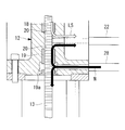
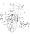
- FIG. 1 It is a longitudinal section showing a main steam stop valve concerning a 1st embodiment of the present invention. It is a figure which expands the II section of FIG. 1 and shows 1st Embodiment of this invention. It is a longitudinal cross-sectional view of the steam control valve which shows 2nd Embodiment of this invention.
- valve casing according to an embodiment of the present invention, a valve provided with the same, and a method of preventing atmospheric gas intrusion of the valve casing will be described with reference to the drawings.
- FIG. 1 is a longitudinal sectional view showing an example of a main steam stop valve (valve) according to a first embodiment of the present invention.
- the main steam stop valve 1 is connected to a main steam inlet 2 of a steam turbine (turbine device) (not shown), and includes a valve casing 5 composed of a casing main body 3 and a casing lid 4. Inside the valve casing 5, a steam inlet passage 6 (working fluid flow passage) and a steam outlet passage 7 (working fluid flow passage) are formed horizontally and in a step-like manner, and the ends of these steam passages 6, 7 A valve seat 8 (flow rate control member) is formed in a portion where the parts overlap.
- a steam inlet passage 6 working fluid flow passage
- a steam outlet passage 7 working fluid flow passage
- valve body sliding cylinder 10 formed on the casing lid 4 so that the piston-like valve body 9 (flow control member) for opening and closing the valve seat 8 is orthogonal to the passage direction of the steam passages 6 and 7 Sliding up and down to open and close the valve seat 8.
- a valve shaft holding portion 12 is provided on the opposite side (lower side) of the valve seat 8 to the valve casing 5 across the steam outlet passage 7, and the valve shaft 13 (flow control member) is provided to the valve shaft holding portion 12. Is held slidably in the axial direction.
- One end (upper end) of the valve shaft 13 is connected to the valve body 9, the middle portion penetrates the valve shaft holding portion 12, and the other end (lower end) is cupped to the actuator 14 installed outside the valve casing 5. It is connected via a ring 15.
- the actuator 14 When the actuator 14 is actuated, the valve shaft 13 slides in the axial direction to move the valve body 9 to open and close the valve seat 8 (in FIG. 1, the valve body 9 is closed).
- the main steam (working fluid) supplied to the steam turbine flows from the steam inlet passage 6 through the valve seat 8 to the steam outlet passage 7, and when the valve body 9 closes the valve seat 8 The flow of steam stops.
- the pressure of the main steam ST is higher than atmospheric pressure (0 barg), and is about 5 barg at a low level and about 60 barg at a high level.
- the valve shaft holding portion 12 is provided with a bearing-like upper guide bush 18 and a lower guide bush 19 for supporting the valve shaft 13.
- the shaft holes 20 formed in the upper and lower guide bushes 18 and 19 are provided.
- the valve stem 13 is slidably inserted.
- a labyrinth structure is provided between the shaft hole 20 and the valve shaft 13 so as to minimize leakage of the main steam.
- the valve shaft holding portion 12 is provided with a leak fluid recovery passage.
- the seal steam receiver passage 21 and the ground steam condenser return passage 22 communicate with the valve shaft holding portion 12.
- part of the main steam in the steam outlet passage 7 passes between the valve shaft 13 and the upper and lower guide bushes 18 and 19 (shaft holes 20), and is on the atmosphere side (outside)
- the leaked vapor (LS: leaked fluid) to be leaked to the air is guided to a predetermined place by utilizing the pressure difference with the steam outlet passage 7 to prevent the leaked vapor from leaking to the atmosphere side. is there.
- the upper guide bush 18 and the lower guide bush 19 are provided with leak-off chambers 18a and 19a at their respective intermediate portions.
- One end of the seal vapor receiver passage 21 is connected to the leak-off chamber 18a, and the other end is connected to the seal vapor receiver 24 (leak fluid recovery unit).
- the pressure of the seal steam receiver passage 21 is set to, for example, about 0.1 barg.
- the grand steam condenser return passage 22 is provided on the atmosphere side (outside) of the seal steam receiver passage 21, and one end thereof is between the upper guide bush 18 and the lower guide bush 19. The other end is connected to the ground steam condenser 25 (leak fluid recovery unit). For example, a negative pressure of about -0.02 barg is applied to the ground steam condenser return passage 22.
- leaked steam (flowed from the steam outlet passage 7 to the leak-off chamber 18 a by passing between the valve shaft 13 and the upper guide bush 18 (shaft hole 20) Leak fluid) is led to the seal steam receiver passage 21 and the ground steam condenser return passage 22 from the pressure difference and flows to the seal steam receiver 24 or the ground steam condenser 25. This prevents the leaked vapor from leaking from the valve shaft holding portion 12 to the atmosphere side.
- the pressure of about 0.1 barg set in the seal steam receiver passage 21 causes the seal steam to flow from the seal steam receiver passage 21 to the atmosphere side.
- the seal steam flows to the ground steam condenser return passage 22 which is a negative pressure and flows to the ground steam condenser 25, so it does not leak to the atmosphere.
- the valve shaft holding portion 12 is inactive so as to be connected to the atmosphere side (lower side) than the ground steam condenser return passage 22 which is a leak fluid recovery passage.
- a gas supply passage 28 is provided. One end of the inert gas supply passage 28 communicates with, for example, the leak-off chamber 19 a of the lower guide bush 19, and the other end is connected to the air supply pump 30.
- An air component separator 29 and a gas flow check unit 31 are connected to an intermediate portion of the inert gas supply passage 28.
- An inert gas supply unit 32 is configured to include the inert gas supply passage 28, the air component separator 29, the air supply pump 30, and the gas flow check unit 31. The inert gas supply unit 32 supplies an inert gas to the shaft hole 20 of the valve shaft holder 12 and fills the inert gas in the shaft hole 20.
- an inexpensive nitrogen gas is preferable as a gas used as the inert gas in the inert gas supply unit 32, it is not necessarily limited to the nitrogen gas, and may be another kind of inert gas such as argon gas. Is also conceivable.
- the nitrogen gas is supplied at a pressure (for example, about 0.1 barg) higher than the atmospheric pressure, and the flow of the nitrogen gas can be confirmed by the gas flow check unit 31.
- the gas flow check unit 31 has, for example, a configuration in which pressure measurement units 35 and 36 are provided on the upstream and downstream sides of the orifice 34 for narrowing the flow passage of the inert gas supply passage 28. The gas flow rate is calculated.
- the air component separator 29 is, for example, of a known filter structure that takes out only nitrogen gas from the air, is supplied with air at atmospheric pressure or compressed air, and generates nitrogen gas from this air.
- the valve seat 8 opens and the main steam flows from the steam inlet passage 6 to the valve seat 8. Flow to the steam outlet passage 7 and then to the main steam inlet 2 of the steam turbine. This operates the steam turbine.
- the nitrogen gas separated from the air in the air component separator 29 is supplied from the inert gas supply passage 28 to the valve shaft holding unit 12 by the air supply pump 30. Ru. Therefore, the inside (the gap with the valve shaft 23) of the shaft hole 20 of the valve shaft holding portion 12 is filled with nitrogen gas, and a part of the nitrogen gas is the gap between the shaft hole 20 and the valve shaft 13 Flow out to the atmosphere side (outside). As a result, the air around the main steam stop valve 1 can not enter the inside of the valve shaft holding portion 12. Nitrogen gas that has not flowed out to the atmosphere side is sucked into the grand steam condenser return passage 22.
- the flammable gas can be prevented from being sucked into the main steam stop valve 1.
- the activation gas oxygen and the like
- the inert gas supply passage 28 is connected to the atmosphere side more than the ground steam condenser return passage 22 which is a leak fluid recovery passage.
- a negative pressure of, for example, about -0.02 barg is applied to the grand steam condenser return passage 22, and the nitrogen gas flowing through the inert gas supply passage 28 is, for example, about 0.1 barg more than atmospheric pressure. High pressure is applied. Therefore, the nitrogen gas supplied from the inert gas supply unit 32 to the valve shaft holding unit 12 easily flows into the inside of the valve shaft holding unit 12 due to the pressure difference with the ground steam condenser return passage 22. Therefore, the inside of the valve shaft holding portion 12 can be reliably filled with the inert gas, and outside air or liquid can be prevented from entering the inside of the main steam stop valve 1.
- the pressure of the nitrogen gas flowing through the inert gas supply passage 28 is set higher than the atmospheric pressure, and the inert gas supply passage 28 is provided with the gas flow check unit 31 for confirming the flow of nitrogen gas. There is. For this reason, it is possible to confirm the flow of nitrogen gas supplied to the main steam stop valve 1, prevent the nitrogen gas supply from being stagnant, and liquid such as ambient air or rain water inside the main steam stop valve 1 It can be prevented from entering.
- the inert gas can be procured inexpensively.
- nitrogen gas is separated from the air by the air component separator 29 provided in the inert gas supply unit 32 and used as the inert gas
- nitrogen gas from the air at the installation site of the main steam stop valve 1 is It can be separated and used as an inert gas. Therefore, it is not necessary to purchase pure nitrogen gas and carry it to the installation site of the main steam stop valve 1 or to replenish it, so that nitrogen gas as inert gas can be easily and inexpensively procured.
- FIG. 3 is a longitudinal sectional view of a steam control valve according to a second embodiment of the present invention.
- the steam control valve 41 is installed at a main steam inlet or the like of a steam turbine (not shown), and is a valve casing including a casing main body 43 and a casing lid 44. It has 45.
- a valve chamber 46 (working fluid flow passage) is provided inside the valve casing 45, and a steam inlet passage 47 (working fluid flow passage) is horizontally connected to the valve chamber 46, and a steam outlet passage 48 (working fluid flow passage). ) are connected from below.
- the steam inlet passage 47 extends in a direction perpendicular to the paper surface.
- a valve seat 50 is provided at an opening portion of the steam outlet passage 48 in the valve chamber 46, and a valve shaft holding portion 51 is formed on the casing lid 44 so as to be located directly above the valve seat 50.
- the valve shaft 52 is slidably held in the axial direction by the valve shaft holding portion 51, and a valve body 53 for opening and closing the valve seat 50 is connected to one end (lower end) of the valve shaft 52.
- An intermediate portion of the valve shaft 52 penetrates the valve shaft holding portion 51 and protrudes to the outside, and the other end (upper end) of the valve shaft 52 is a shaft around the pivot shaft 56 of the lever bracket 55 installed outside the casing lid 44.
- the intermediate portion of the supported opening / closing lever 57 is rotatably connected via a coupling 58.
- the free end of the opening / closing lever 57 is connected to an actuator (not shown).
- the open / close lever 57 pivots up and down with the pivot shaft 56 of the lever bracket 55 as a fulcrum, and the valve shaft 52 slides up and down.
- the valve seat 50 is moved up and down.
- the valve body 53 moves upward, the valve seat 50 opens, and the main steam (working fluid) supplied to the steam turbine passes from the steam inlet passage 47 through the valve chamber 46 through the valve seat 50 as shown by the arrow ST. , Flow to the steam outlet passage 48.
- the amount of this main steam is adjusted according to the position of the valve body 53, that is, the amount of rotation of the opening / closing lever 57. In FIG. 3, the valve body 53 is closed.
- the valve shaft holding portion 51 is provided with a bearing-like guide bush 61 for supporting the valve shaft 52.
- the valve shaft 52 is slidably inserted in a shaft hole 60 formed in the guide bush 61. There is.
- a labyrinth structure is provided between the shaft hole 60 and the valve shaft 52 to reduce leakage of the main steam as much as possible, but since the leakage can not be completely prevented, the valve shaft is held.
- the portion 51 is provided with a leak fluid recovery passage.
- the seal steam receiver passage 62 and the ground steam condenser return passage 63 communicate with the valve shaft holding portion 51.
- part of the main steam in the valve chamber 46 tends to leak between the valve shaft 52 and the guide bush 61 (shaft hole 60) to the atmosphere side (outside)
- the leaked vapor LS: leaked fluid
- a leak off chamber 64 is provided in the middle of the guide bush 61, and independent leak off chambers 65 and 66 are provided on the top of the guide bush 61.
- One end of the seal steam receiver passage 62 is connected to the leak-off chamber 64, and the other end is connected to the seal steam receiver 68 (leak fluid recovery unit).
- the pressure of the seal steam receiver passage 62 is set to, for example, about 0.1 barg.
- the ground steam condenser return passage 63 is provided on the atmosphere side (outside) of the seal steam receiver passage 62, one end thereof communicates with the leak-off chamber 65, and the other end is the ground steam condenser 69 It is connected to the leak fluid recovery part).
- a negative pressure of about -0.02 barg is applied to the ground steam condenser return passage 63.
- leaked vapor that has flowed from the valve chamber 46 between the valve stem 52 and the guide bush 61 (shaft hole 60) and flowed to the leak off chamber 64 is From the pressure difference, it is led to the seal steam receiver passage 62 and the ground steam condenser return passage 63 and flows to the seal steam receiver 68 or the ground steam condenser 69. This prevents the leaked vapor from leaking from the valve shaft holding portion 51 to the air side.
- the valve shaft holding portion 51 is provided with an inert gas supply passage 71 so as to be connected to the atmosphere side (upper side) of the ground steam condenser return passage 63 which is a leak fluid recovery passage.
- One end of the inert gas supply passage 71 communicates with the leak-off chamber 66 formed in the upper portion of the guide bush 61, and the other end is connected to the air supply pump 73.
- An air component separator 72 and a gas flow check unit 74 are connected to an intermediate portion of the inert gas supply passage 71.
- An inert gas supply unit 75 is configured to include an inert gas supply passage 71, an air component separator 72, an air supply pump 73, and a gas flow check unit 74.
- the inert gas supply unit 75 supplies the inert gas to the shaft hole 60 of the valve shaft holding unit 51 to prevent the inert gas from being discharged into the shaft hole 60. It is filled with an active gas, and nitrogen gas is used as an inert gas. The nitrogen gas is supplied at a pressure (for example, about 0.1 barg) higher than the atmospheric pressure, and the flow of the nitrogen gas can be confirmed by the gas flow check unit 74. Since the configuration of the gas flow check unit 74 is the same as that of the gas flow check unit 31 in the first embodiment, the same reference numerals are given to the respective constituent portions and the description will be omitted.
- the air component separator 72 like the air component separator 29 in the first embodiment, has a known filter structure for extracting only nitrogen gas from the air, and supplies air at atmospheric pressure or compressed air. And generate nitrogen gas from this air.
- the nitrogen gas separated from the air in the air component separator 72 is inactivated by the air supply pump 73.
- the gas is supplied from the gas supply passage 71 to the valve shaft holder 51. Therefore, the inside (the gap with the valve shaft 52) of the shaft hole 60 of the valve shaft holding portion 51 is filled with nitrogen gas, and a part of the nitrogen gas is the gap between the shaft hole 60 and the valve shaft 52 Flow out to the atmosphere side (outside).
- air around the steam control valve 41 can not enter the inside of the valve shaft holding portion 51.
- the nitrogen gas that has not flowed out to the atmosphere side is sucked into the grand steam condenser return passage 63.
- the flammable gas can be prevented from being sucked into the steam control valve 41.
- the activation gas oxygen or the like
- the inert gas supply passage 71 is connected to the atmosphere side of the ground steam condenser return passage 63 which is a leak fluid recovery passage, the nitrogen supplied from the inert gas supply unit 75 to the valve shaft holding unit 51 Gas is likely to flow into the valve shaft holding portion 51 due to the pressure difference with the ground steam condenser return passage 63. Therefore, the inside of the valve shaft holding portion 51 can be reliably filled with the inert gas, and it is possible to prevent the outside air or the liquid from entering the inside of the steam control valve 41.
- the valve casings 5, 45 according to the embodiment of the present invention, the steam valve (the main steam stop valve 1, the steam control valve 41, etc.) including the same, the steam turbine including the steam valve, and the valve casing
- the atmosphere gas intrusion preventing method of the present invention the gas around the steam valve 1, 41 is prevented from entering the inside of the valve shaft holding portion 12, 51, and the danger of ignition is eliminated and the active gas contained in the air (Oxygen etc.) enters the inside of the valve shaft holding portion 12, 51 to prevent sticking due to oxidation of the valve shaft holding portion 12, 51 and the valve shaft 13, 52 etc. You can keep sex long.
- the present invention is not limited only to the configuration of the above embodiment, and can be appropriately modified or improved, and an embodiment with such modification or improvement is also included in the scope of the present invention. .
- this invention can be applied to a gas valve etc., for example.
Landscapes
- Engineering & Computer Science (AREA)
- General Engineering & Computer Science (AREA)
- Mechanical Engineering (AREA)
- Details Of Valves (AREA)
- Control Of Turbines (AREA)
- Lift Valve (AREA)
Abstract
弁(1)の弁ケーシング(5)は、作動流体(ST)が流れる作動流体流路(6,7)と、前記作動流体流路(6,7)の内部において作動流体(ST)の流量を制御する流量制御部材(8,9,13)のうちの少なくとも弁軸(13)を収容するとともに作動流体流路(6,7)に一端部が接続された弁軸保持部(12)と、を備え、前記弁軸保持部(12)は、弁軸(13)の軸用穴(20)に不活性ガス(N)を供給する不活性ガス供給部(32)を備えている。これにより、弁(1)周囲の雰囲気に含まれる可燃性ガスや活性ガスが弁軸保持部(12)に入ることを防止することができる。
Description
本発明は、浮体式生産貯蔵積出設備(FPSO)に配備される蒸気タービンの蒸気弁等における弁ケーシング、これを備えた弁、弁を備えたタービン装置、および弁ケーシングの雰囲気ガス侵入防止方法に関するものである。
特許文献1に開示されているように、蒸気タービンの主蒸気入口に設置される主蒸気止め弁や蒸気加減弁等の蒸気弁において、弁ケーシングの弁軸保持部から高温、高圧な主蒸気が外部にリークすることを防止するべく、ガイドブッシュ(弁軸保持部)をラビリンス構造にするとともに、このラビリンス構造を2段に構成し、その間にリークオフ室を設けて、1段目のラビリンス構造を通過したリーク蒸気をリークオフ室からリーク蒸気出口に送るようにしたものが知られている。
洋上で天然ガスを生産して備蓄する浮体式生産貯蔵積出設備(floating
production, storage and offloading:略称FPSO)等のデッキ上に設置される蒸気タービンに用いる蒸気弁においては、弁軸保持部からの主蒸気のリークを防止することに加えて、蒸気タービンの周囲の空気中に含まれる可燃性ガスが弁軸保持部に侵入することを防止する必要がある。
production, storage and offloading:略称FPSO)等のデッキ上に設置される蒸気タービンに用いる蒸気弁においては、弁軸保持部からの主蒸気のリークを防止することに加えて、蒸気タービンの周囲の空気中に含まれる可燃性ガスが弁軸保持部に侵入することを防止する必要がある。
特に、蒸気弁から漏洩した主蒸気を復水器に導くためにリークオフ室やリーク蒸気出口に負圧領域が形成されることがある。リークオフ室やリーク蒸気出口に負圧領域が形成される場合、蒸気弁の周囲の空気中に含まれる可燃性ガスが弁軸保持部吸引されてしまう虞がある。
また、空気中に含まれる可燃性ガスに限らず、空気に含まれる活性ガス(酸素等)が弁軸保持部に侵入することにより、弁軸保持部および弁軸等が酸化し、蒸気弁が固着する虞がある。特にFPSO上においては、蒸気タービンが長期間(例えば数年間)の連続運転を求められるため、蒸気弁の固着を防止する必要がある。
本発明は、このような事情に鑑みてなされたものであって、弁周囲の雰囲気に含まれる可燃性ガスや活性ガスが弁軸保持部に侵入することを防止することができる弁ケーシング、これを備えた弁、弁を備えたタービン装置、および弁ケーシングの雰囲気ガス侵入防止方法を提供することを目的とする。
上記課題を解決するために、本発明は、以下の手段を採用する。
即ち、本発明の第1態様に係る弁ケーシングは、作動流体が流れる作動流体流路と、前記作動流体流路の内部において前記作動流体の流量を制御する流量制御部材のうちの少なくとも弁軸を収容するとともに前記作動流体流路に一端部が接続された弁軸保持部と、を備え、前記弁軸保持部は、前記弁軸の軸用穴に不活性ガスを供給する不活性ガス供給部を備えたものである。
この弁ケーシングによれば、不活性ガス供給部から弁軸保持部の軸用穴に不活性ガスが供給され、この不活性ガスは軸用穴と弁軸との間の隙間から外部に流出する。このため、弁の周囲の空気等の気体が軸用穴から弁軸保持部の内部に入り込めなくなる。したがって、例えば弁の周囲雰囲気中に可燃性ガスが含まれていても、この可燃性ガスが弁の内部に吸引されることがない。しかも、空気に含まれる活性ガス(酸素等)が弁軸保持部に侵入して弁軸保持部および弁軸等を酸化させることによる固着も防止できる。
上記構成の弁ケーシングにおいて、前記弁軸保持部には、前記作動流体流路の内部からリークしたリーク流体を、前記作動流体流路との圧力差を利用してリーク流体回収部に導くリーク流体回収通路が設けられ、前記不活性ガス供給部は前記リーク流体回収通路よりも大気側に接続されていることが好ましい。
これにより、不活性ガス供給部から弁軸保持部の軸用穴に供給された不活性ガスが、リーク流体回収部との圧力差によって弁軸保持部の内部に流れ込みやすくなる。したがって、弁軸保持部の内部に不活性ガスを確実に供給し、弁の内部に外気が入ることを防止することができる。
上記構成の弁ケーシングにおいて、前記不活性ガスは大気圧よりも高圧で供給され、該不活性ガスの流通を確認するガス流通確認部が設けられていることが好ましい。
これにより、弁軸保持部に供給される不活性ガスの流通を確認することができ、不活性ガスの供給が滞ることを防止して、弁軸保持部の内部に外気が入ることを防止することができる。
上記構成の弁ケーシングにおいて、前記不活性ガスは窒素ガスであることが好ましい。窒素ガスを不活性ガスとして用いることにより、不活性ガスを安価に調達することができる。
上記構成の弁ケーシングにおいて、前記不活性ガス供給部は、空気中から窒素ガスを分離する空気成分分離器に繋がっており、この空気成分分離器にて分離された窒素ガスを前記不活性ガスとして用いるようにしてもよい。
このように空気成分分離器によって空気中から窒素ガスを分離し、この窒素ガスを不活性ガスとして用いることにより、純粋な窒素ガスを購入して弁の設置現場まで運んだり、補充したりすることなく、現場の空気から窒素ガスを分離して不活性ガスとして使用することができ、不活性ガスの調達が容易かつ安価になる。
本発明の第2態様に係る弁は、前記のいずれかの態様の弁ケーシングを備えている。これにより、弁の周囲の空気中に含まれる可燃性ガスや活性ガスが弁軸保持部に入ることを防止することができる。
本発明の第3態様に係るタービン装置は、前記態様の弁を備えたものである。
このタービン装置では、不活性ガス供給部から弁の弁軸保持部の軸用穴に不活性ガスが供給されるため、弁の周囲の空気や可燃性ガス等の気体が軸用穴から弁軸保持部の内部に入り込めなくなる。したがって、例えば弁の周囲雰囲気中に可燃性ガスが含まれていても、この可燃性ガスが弁の内部に吸引されることがない。
また、空気に含まれる活性ガス(酸素等)が弁軸保持部に侵入しないため、弁軸保持部および弁軸等を酸化させることによる固着も防止でき、タービン装置の安全性と信頼性を高めることができる。
このタービン装置では、不活性ガス供給部から弁の弁軸保持部の軸用穴に不活性ガスが供給されるため、弁の周囲の空気や可燃性ガス等の気体が軸用穴から弁軸保持部の内部に入り込めなくなる。したがって、例えば弁の周囲雰囲気中に可燃性ガスが含まれていても、この可燃性ガスが弁の内部に吸引されることがない。
また、空気に含まれる活性ガス(酸素等)が弁軸保持部に侵入しないため、弁軸保持部および弁軸等を酸化させることによる固着も防止でき、タービン装置の安全性と信頼性を高めることができる。
本発明の第3態様に係る弁ケーシングの雰囲気ガス侵入防止方法は、作動流体が流れる作動流体流路と、前記作動流体流路の内部において前記作動流体の流量を制御する流量制御部材のうちの少なくとも弁軸を収容するとともに前記作動流体流路に一端部が接続された弁軸保持部と、を備えた弁ケーシングの雰囲気ガス侵入防止方法であって、前記弁軸保持部における前記弁軸の軸用穴に不活性ガスを供給するものである。
この弁ケーシングの雰囲気ガス侵入防止方法によれば、弁軸保持部の軸用穴に不活性ガスが供給されるため、弁の周囲の空気や可燃性ガス等の気体が弁軸保持部の内部に入り込めなくなる。しかも、空気に含まれる活性ガス(酸素等)が弁軸保持部に侵入して弁軸保持部および弁軸等を酸化させることによる固着も防止できる。
上記の雰囲気ガス侵入防止方法においては、前記弁軸保持部に、前記作動流体流路の内部からリークしたリーク流体を、前記作動流体流路との圧力差を利用してリーク流体回収部に導くリーク流体回収通路を設け、前記不活性ガスを、前記リーク流体回収通路よりも大気側の位置に供給するのが好ましい。
これにより、不活性ガス供給部から弁軸保持部の軸用穴に供給された不活性ガスが、リーク流体回収部との圧力差によって弁軸保持部の内部に流れ込みやすくなる。したがって、弁軸保持部の内部に不活性ガスを確実に供給し、弁の内部に外気が入ることを防止することができる。
以上のように、本発明に係る弁ケーシング、これを備えた弁、弁を備えたタービン装置、および弁ケーシングの雰囲気ガス侵入防止方法によれば、弁の周囲の雰囲気に含まれる可燃性ガスや活性ガスが弁軸保持部に侵入することを防止することができる。
以下に、本発明の実施形態に係る弁ケーシング、これを備えた弁、および弁ケーシングの雰囲気ガス侵入防止方法について、図面を参照しながら説明する。
[第1実施形態]
図1は、本発明の第1実施形態に係る主蒸気止め弁(弁)の一例を示す縦断面図である。
この主蒸気止め弁1は、図示しない蒸気タービン(タービン装置)の主蒸気入口2に接続されるものであり、ケーシング本体3とケーシング蓋4とからなる弁ケーシング5を備えている。弁ケーシング5の内部には蒸気入口通路6(作動流体流路)と蒸気出口通路7(作動流体流路)とが水平、且つ段違い状に形成されており、これらの蒸気通路6,7の端部同士が重なる部分に弁座8(流量制御部材)が形成されている。そして、この弁座8を開閉するピストン状の弁体9(流量制御部材)が、蒸気通路6,7の通路方向に直交するようにケーシング蓋4に形成された弁体摺動シリンダ10の内部を上下に摺動して弁座8を開閉するようになっている。
図1は、本発明の第1実施形態に係る主蒸気止め弁(弁)の一例を示す縦断面図である。
この主蒸気止め弁1は、図示しない蒸気タービン(タービン装置)の主蒸気入口2に接続されるものであり、ケーシング本体3とケーシング蓋4とからなる弁ケーシング5を備えている。弁ケーシング5の内部には蒸気入口通路6(作動流体流路)と蒸気出口通路7(作動流体流路)とが水平、且つ段違い状に形成されており、これらの蒸気通路6,7の端部同士が重なる部分に弁座8(流量制御部材)が形成されている。そして、この弁座8を開閉するピストン状の弁体9(流量制御部材)が、蒸気通路6,7の通路方向に直交するようにケーシング蓋4に形成された弁体摺動シリンダ10の内部を上下に摺動して弁座8を開閉するようになっている。
弁ケーシング5には、蒸気出口通路7を挟んで弁座8の反対側(下側)に弁軸保持部12が設けられており、この弁軸保持部12に弁軸13(流量制御部材)が軸方向に摺動自在に保持されている。この弁軸13は、その一端(上端)が弁体9に連結され、中間部が弁軸保持部12を貫通し、他端(下端)が弁ケーシング5の外部に設置されたアクチュエータ14にカップリング15を介して連結されている。アクチュエータ14が作動すると、弁軸13が軸方向に摺動して弁体9を動かし、弁座8を開閉させる(図1では弁体9が閉じられている)。矢印STで示すように、蒸気タービンに供給される主蒸気(作動流体)は、蒸気入口通路6から弁座8を通り抜けて蒸気出口通路7に流れ、弁体9が弁座8を閉じると主蒸気の流れが止まる。主蒸気STの圧力は、大気圧(0barg)よりも高圧であり、低い物で5barg程度、高いもので60barg程度である。
弁軸保持部12には、弁軸13を支持する軸受状の上部ガイドブッシュ18と下部ガイドブッシュ19とが設けられており、これら上下のガイドブッシュ18,19に形成された軸用穴20に弁軸13が摺動自在に挿入されている。軸用穴20と弁軸13との間にはラビリンス構造が設けられていて、主蒸気のリークが極力少なくなるようにされている。しかし、リークを完全に阻止することはできないため、弁軸保持部12にはリーク流体回収通路が設けられている。
このリーク流体回収通路として、弁軸保持部12にはシール蒸気レシーバ通路21とグランド蒸気復水器戻り通路22とが連通している。これらの通路21,22は、蒸気出口通路7内の主蒸気の一部が、弁軸13と上下のガイドブッシュ18,19(軸用穴20)との間を通過して大気側(外部)に漏洩しようとするリーク蒸気(LS:リーク流体)を、蒸気出口通路7との圧力差を利用して所定の場所に導くことにより、該リーク蒸気が大気側に漏洩することを防止するものである。
上部ガイドブッシュ18と下部ガイドブッシュ19には、それぞれその中間部にリークオフ室18a,19aが設けられている。シール蒸気レシーバ通路21は、その一端がリークオフ室18aに接続され、他端がシール蒸気レシーバ24(リーク流体回収部)に接続されている。シール蒸気レシーバ通路21の圧力は、例えば0.1barg程度に設定されている。
一方、グランド蒸気復水器戻り通路22は、シール蒸気レシーバ通路21よりも大気側(外側)に設けられており、その一端が上部ガイドブッシュ18と下部ガイドブッシュ19との間となる弁軸13の挿入通路に連通し、他端がグランド蒸気復水器25(リーク流体回収部)に接続されている。グランド蒸気復水器戻り通路22には、例えば-0.02barg程度の負圧が掛けられている。
図1および図2中に矢印LSで示すように、蒸気出口通路7から、弁軸13と上部ガイドブッシュ18(軸用穴20)との間を通過してリークオフ室18aに流れたリーク蒸気(リーク流体)は、その圧力差から、シール蒸気レシーバ通路21やグランド蒸気復水器戻り通路22に導かれてシール蒸気レシーバ24、またはグランド蒸気復水器25に流れる。これにより、リーク蒸気が弁軸保持部12から大気側にリークすることが防止される。
蒸気出口通路7から蒸気がリークしていない時には、シール蒸気レシーバ通路21に設定されている0.1barg程度の圧力によって、シール蒸気レシーバ通路21からシール蒸気が大気側に流れ出ようとする。しかし、このシール蒸気は、負圧であるグランド蒸気復水器戻り通路22に流れ、グランド蒸気復水器25に流れるので大気側に漏洩することはない。
図2にも拡大して示すように、弁軸保持部12には、リーク流体回収通路であるグランド蒸気復水器戻り通路22よりも大気側(下側)に接続されるように、不活性ガス供給通路28が設けられている。この不活性ガス供給通路28は、その一端が、例えば下部ガイドブッシュ19のリークオフ室19aに連通し、他端が送気ポンプ30に接続されている。不活性ガス供給通路28の中間部には空気成分分離器29とガス流通確認部31とが接続されている。不活性ガス供給通路28と、空気成分分離器29と、送気ポンプ30と、ガス流通確認部31とを含んで不活性ガス供給部32が構成されている。この不活性ガス供給部32は、弁軸保持部12の軸用穴20に不活性ガスを供給し、軸用穴20の内部に不活性ガスを満たすものである。
この不活性ガス供給部32において、不活性ガスとして用いる気体としては安価な窒素ガスが好ましいが、必ずしも窒素ガスに限定されることはなく、アルゴンガス等、他の種の不活性ガスとすることも考えられる。
窒素ガスは大気圧よりも高い圧力(例えば0.1barg程度)で供給され、この窒素ガスの流通をガス流通確認部31によって確認することができる。ガス流通確認部31は、例えば不活性ガス供給通路28の流路を絞るオリフィス34の上下流側に圧力測定部35,36を設けた構成であり、圧力測定部35,36の差圧から窒素ガスの流量を算出するものである。
空気成分分離器29は、例えば空気中から窒素ガスだけを取り出す公知のフィルター構造のものであり、大気圧の空気、または圧縮された空気を供給され、この空気から窒素ガスを生成する。
以上のように構成された主蒸気止め弁1において、アクチュエータ14が弁軸13を押し上げて弁体9を弁座8から離すと弁座8が開き、主蒸気が蒸気入口通路6から弁座8を通り抜けて蒸気出口通路7に流れ、さらに蒸気タービンの主蒸気入口2に流れる。これによって蒸気タービンが作動する。
不活性ガス供給部32においては、矢印Nで示すように、空気成分分離器29において空気から分離された窒素ガスが送気ポンプ30によって不活性ガス供給通路28から弁軸保持部12に供給される。このため、弁軸保持部12の軸用穴20の内部(弁軸23との隙間)が窒素ガスで満たされ、この窒素ガスの一部が軸用穴20と弁軸13との間の隙間から大気側(外部)に流出する。これにより、主蒸気止め弁1の周囲の空気が弁軸保持部12の内部に入り込めなくなる。大気側に流出しなかった窒素ガスはグランド蒸気復水器戻り通路22に吸引される。
したがって、例えば主蒸気止め弁1の周囲雰囲気中に可燃性ガスが含まれていても、この可燃性ガスが主蒸気止め弁1の内部に吸引されることを防止できる。しかも、空気に含まれる活性ガス(酸素等)が弁軸保持部12の内部に侵入して弁軸保持部12および弁軸13等を酸化させることによる固着も防止できる。
不活性ガス供給通路28は、リーク流体回収通路であるグランド蒸気復水器戻り通路22よりも大気側に接続されている。前述のように、グランド蒸気復水器戻り通路22には例えば-0.02barg程度の負圧が掛けられ、不活性ガス供給通路28を流れる窒素ガスには、例えば大気圧よりも0.1barg程度高い圧力が付与されている。このため、不活性ガス供給部32から弁軸保持部12に供給された窒素ガスが、グランド蒸気復水器戻り通路22との圧力差によって弁軸保持部12の内部に流れ込みやすくなる。したがって、弁軸保持部12の内部を不活性ガスによって確実に満たし、主蒸気止め弁1の内部に外気や液体が入ることを防止することができる。
上記のように不活性ガス供給通路28を流れる窒素ガスの圧力は大気圧よりも高く設定され、不活性ガス供給通路28には、窒素ガスの流通を確認するガス流通確認部31が設けられている。このため、主蒸気止め弁1に供給される窒素ガスの流通を確認することができ、窒素ガスの供給が滞ることを防止して、主蒸気止め弁1の内部に外気や雨水等の液体が入ることを防止することができる。
さらに、主蒸気止め弁1の弁軸保持部12の内部に供給する不活性ガスとして窒素ガスを使用することにより、不活性ガスを安価に調達することができる。
特に、不活性ガス供給部32に設けられた空気成分分離器29によって空気中から窒素ガスを分離して不活性ガスとして用いているため、主蒸気止め弁1の設置現場の空気から窒素ガスを分離して不活性ガスとして使用することができる。したがって、純粋な窒素ガスを購入して主蒸気止め弁1の設置現場まで運んだり、補充したりする必要がなく、不活性ガスとしての窒素ガスの調達が容易かつ安価に行える。
このようにして、主蒸気止め弁1の周囲の空気や可燃性のガス等が弁軸保持部12の内部に侵入することを防止するとともに、弁軸保持部12付近の酸化による固着を防止して蒸気タービンの安全性と信頼性を高めることができる。
[第2実施形態]
図3は、本発明の第2実施形態を示す蒸気加減弁の縦断面図である。
この蒸気加減弁41は、第1実施形態における主蒸気止め弁1と同様に、図示しない蒸気タービンの主蒸気入口等に設置されるものであり、ケーシング本体43とケーシング蓋44とからなる弁ケーシング45を備えている。弁ケーシング45の内部には弁室46(作動流体流路)が設けられ、この弁室46に、蒸気入口通路47(作動流体流路)が水平に繋がり、蒸気出口通路48(作動流体流路)が下方から繋がっている。図3において、蒸気入口通路47は紙面に直交する方向に延びている。
図3は、本発明の第2実施形態を示す蒸気加減弁の縦断面図である。
この蒸気加減弁41は、第1実施形態における主蒸気止め弁1と同様に、図示しない蒸気タービンの主蒸気入口等に設置されるものであり、ケーシング本体43とケーシング蓋44とからなる弁ケーシング45を備えている。弁ケーシング45の内部には弁室46(作動流体流路)が設けられ、この弁室46に、蒸気入口通路47(作動流体流路)が水平に繋がり、蒸気出口通路48(作動流体流路)が下方から繋がっている。図3において、蒸気入口通路47は紙面に直交する方向に延びている。
弁室46における蒸気出口通路48の開口部分に弁座50が設けられており、ケーシング蓋44には弁座50の真上に位置するように弁軸保持部51が形成されている。この弁軸保持部51に弁軸52が軸方向に摺動自在に保持され、弁軸52の一端(下端)に、弁座50を開閉する弁体53が連結されている。弁軸52の中間部は弁軸保持部51を貫通して外部に突出し、弁軸52の他端(上端)は、ケーシング蓋44の外部に設置されたレバーブラケット55の回動軸56に軸支された開閉レバー57の中間部にカップリング58を介して回動自在に連結されている。開閉レバー57の自由端は図示しないアクチュエータに連結されている。
この蒸気加減弁41において、図示しないアクチュエータが作動すると、開閉レバー57がレバーブラケット55の回動軸56を支点にして上下に回動し、弁軸52が上下に摺動して弁体53を弁座50に対して上下動させる。弁体53が上方に動くと弁座50が開き、矢印STで示すように、蒸気タービンに供給される主蒸気(作動流体)が、蒸気入口通路47から弁室46を経て弁座50を通り抜け、蒸気出口通路48に流れる。この主蒸気の量は、弁体53の位置、即ち開閉レバー57の回動量に応じて加減される。図3では弁体53が閉じられている。
弁軸保持部51には、弁軸52を支持する軸受状のガイドブッシュ61が設けられており、このガイドブッシュ61に形成された軸用穴60に弁軸52が摺動自在に挿入されている。軸用穴60と弁軸52との間にはラビリンス構造が設けられていて、主蒸気のリークが極力少なくなるようにされているが、リークを完全に阻止することはできないため、弁軸保持部51にはリーク流体回収通路が設けられている。
このリーク流体回収通路として、弁軸保持部51にはシール蒸気レシーバ通路62とグランド蒸気復水器戻り通路63とが連通している。これらの通路62,63は、弁室46内の主蒸気の一部が、弁軸52とガイドブッシュ61(軸用穴60)との間を通過して大気側(外部)に漏洩しようとするリーク蒸気(LS:リーク流体)を、弁室46との圧力差を利用して所定の場所に導くことにより、該リーク蒸気が大気側に漏洩することを防止するものである。
ガイドブッシュ61の中間部にはリークオフ室64が設けられ、ガイドブッシュ61の上部には独立したリークオフ室65,66が設けられている。シール蒸気レシーバ通路62は、その一端がリークオフ室64に接続され、他端がシール蒸気レシーバ68(リーク流体回収部)に接続されている。シール蒸気レシーバ通路62の圧力は、例えば0.1barg程度に設定されている。
一方、グランド蒸気復水器戻り通路63は、シール蒸気レシーバ通路62よりも大気側(外側)に設けられており、その一端がリークオフ室65に連通し、他端がグランド蒸気復水器69(リーク流体回収部)に接続されている。グランド蒸気復水器戻り通路63には、例えば-0.02barg程度の負圧が掛けられている。
図3中に矢印LSで示すように、弁室46から、弁軸52とガイドブッシュ61(軸用穴60)との間を通過してリークオフ室64に流れたリーク蒸気(リーク流体)は、その圧力差から、シール蒸気レシーバ通路62やグランド蒸気復水器戻り通路63に導かれてシール蒸気レシーバ68、またはグランド蒸気復水器69に流れる。これにより、リーク蒸気が弁軸保持部51から大気側にリークすることが防止される。
弁室46から蒸気がリークしていない時には、シール蒸気レシーバ通路62に設定されている0.1barg程度の圧力によって、シール蒸気レシーバ通路62からシール蒸気が大気側に流れ出ようとする。しかし、このシール蒸気は、負圧であるグランド蒸気復水器戻り通路63に流れ、グランド蒸気復水器69に流れるので大気側に漏洩することはない。
弁軸保持部51には、リーク流体回収通路であるグランド蒸気復水器戻り通路63よりも大気側(上側)に接続されるように、不活性ガス供給通路71が設けられている。この不活性ガス供給通路71は、その一端が、ガイドブッシュ61の上部に形成されたリークオフ室66に連通し、他端が送気ポンプ73に接続されている。不活性ガス供給通路71の中間部には空気成分分離器72とガス流通確認部74とが接続されている。不活性ガス供給通路71と、空気成分分離器72と、送気ポンプ73と、ガス流通確認部74とを含んで不活性ガス供給部75が構成されている。
この不活性ガス供給部75は、第1実施形態の不活性ガス供給部32と同じく、弁軸保持部51の軸用穴60に不活性ガスを供給して該軸用穴60の内部に不活性ガスを満たすものであり、不活性ガスとして窒素ガスを使用している。窒素ガスは大気圧よりも高い圧力(例えば0.1barg程度)で供給され、この窒素ガスの流通をガス流通確認部74によって確認することができる。ガス流通確認部74の構成は第1実施形態におけるガス流通確認部31と同様であるため、各構成部に同一の符号を付して説明を省略する。
空気成分分離器72は、第1実施形態における空気成分分離器29と同様に、空気中から窒素ガスだけを取り出す公知のフィルター構造のものであり、大気圧の空気、または圧縮された空気を供給され、この空気から窒素ガスを生成する。
以上のように構成された蒸気加減弁41において、不活性ガス供給部75では、矢印Nで示すように、空気成分分離器72において空気から分離された窒素ガスが、送気ポンプ73によって不活性ガス供給通路71から弁軸保持部51に供給される。このため、弁軸保持部51の軸用穴60の内部(弁軸52との隙間)が窒素ガスで満たされ、この窒素ガスの一部が軸用穴60と弁軸52との間の隙間から大気側(外部)に流出する。これにより、蒸気加減弁41の周囲の空気が弁軸保持部51の内部に入り込めなくなる。大気側に流出しなかった窒素ガスはグランド蒸気復水器戻り通路63に吸引される。
したがって、例えば蒸気加減弁41の周囲雰囲気中に可燃性ガスが含まれていても、この可燃性ガスが蒸気加減弁41の内部に吸引されることを防止できる。しかも、空気に含まれる活性ガス(酸素等)が弁軸保持部51の内部に侵入して弁軸保持部51および弁軸52等を酸化させることによる固着も防止できる。
不活性ガス供給通路71は、リーク流体回収通路であるグランド蒸気復水器戻り通路63よりも大気側に接続されているため、不活性ガス供給部75から弁軸保持部51に供給された窒素ガスが、グランド蒸気復水器戻り通路63との圧力差によって弁軸保持部51の内部に流れ込みやすくなる。したがって、弁軸保持部51の内部を不活性ガスによって確実に満たし、蒸気加減弁41の内部に外気や液体が入ることを防止することができる。
以上説明したように、本発明の実施形態に係る弁ケーシング5,45、これを備えた蒸気弁(主蒸気止め弁1、蒸気加減弁41等)、蒸気弁を備えた蒸気タービン、および弁ケーシングの雰囲気ガス侵入防止方法によれば、蒸気弁1,41の周囲の気体が弁軸保持部12,51の内部に入ることを防止し、引火の危険を排除するとともに、空気に含まれる活性ガス(酸素等)が弁軸保持部12,51の内部に侵入して弁軸保持部12,51および弁軸13,52等を酸化させることによる固着を防止して、蒸気弁1,41の健全性を永く保つことができる。
また、このような蒸気弁1,41を蒸気タービンに備えることにより、引火や、弁軸保持部12,51付近における固着の発生を防止して蒸気タービンの安全性と信頼性を高めることができる。
本発明は上記実施形態の構成のみに限定されるものではなく、適宜変更や改良を加えることができ、このように変更や改良を加えた実施形態も本発明の権利範囲に含まれるものとする。
例えば、上記実施形態では蒸気タービンに備えられる蒸気弁(1,41)に本発明を適用した例について説明したが、例えばガス弁等に本発明を応用することができる。
1 主蒸気止め弁(弁)
2 主蒸気入口
5,45 弁ケーシング
6,47 蒸気入口通路(作動流体流路)
7,48 蒸気出口通路(作動流体流路)
8,50 弁座(流量制御部材)
9,53 弁体(流量制御部材)
12,51 弁軸保持部
13,52 弁軸(流量制御部材)
20,60 軸用穴
21,62 シール蒸気レシーバ通路(リーク流体回収通路)
22,63 グランド蒸気復水器戻り通路(リーク流体回収通路)
24,68 シール蒸気レシーバ(リーク流体回収部)
25,69 グランド蒸気復水器(リーク流体回収部)
28,71 不活性ガス供給通路
29,72 空気成分分離器
31,74 ガス流通確認部
32,75 不活性ガス供給部
41 蒸気加減弁(蒸気弁)
46 弁室(蒸気通路作動流体流路)
LS リーク蒸気(リーク流体)
N 窒素(不活性ガス)
ST 主蒸気(作動流体)
2 主蒸気入口
5,45 弁ケーシング
6,47 蒸気入口通路(作動流体流路)
7,48 蒸気出口通路(作動流体流路)
8,50 弁座(流量制御部材)
9,53 弁体(流量制御部材)
12,51 弁軸保持部
13,52 弁軸(流量制御部材)
20,60 軸用穴
21,62 シール蒸気レシーバ通路(リーク流体回収通路)
22,63 グランド蒸気復水器戻り通路(リーク流体回収通路)
24,68 シール蒸気レシーバ(リーク流体回収部)
25,69 グランド蒸気復水器(リーク流体回収部)
28,71 不活性ガス供給通路
29,72 空気成分分離器
31,74 ガス流通確認部
32,75 不活性ガス供給部
41 蒸気加減弁(蒸気弁)
46 弁室(蒸気通路作動流体流路)
LS リーク蒸気(リーク流体)
N 窒素(不活性ガス)
ST 主蒸気(作動流体)
Claims (9)
- 大気圧よりも高圧な作動流体が流れる作動流体流路と、
前記作動流体流路の内部において前記作動流体の流量を制御する流量制御部材のうちの少なくとも弁軸を収容するとともに前記作動流体流路に一端部が接続された弁軸保持部と、を備え、
前記弁軸保持部は、前記弁軸の軸用穴に不活性ガスを供給する不活性ガス供給部を備えた弁ケーシング。 - 前記弁軸保持部には、前記作動流体流路の内部からリークしたリーク流体を、前記作動流体流路との圧力差を利用してリーク流体回収部に導くリーク流体回収通路が設けられ、
前記不活性ガス供給部は前記リーク流体回収通路よりも大気側に接続されている請求項1に記載の弁ケーシング。 - 前記不活性ガスは大気圧よりも高圧で供給され、該不活性ガスの流通を確認するガス流通確認部が設けられている請求項1または2に記載の弁ケーシング。
- 前記不活性ガスは窒素ガスである請求項1から3のいずれかに記載の弁ケーシング。
- 前記不活性ガス供給部は、空気中から窒素ガスを分離する空気成分分離器に繋がっており、この空気成分分離器にて分離された窒素ガスを前記不活性ガスとして用いる請求項4に記載の弁ケーシング。
- 請求項1~5のいずれかに記載の弁ケーシングを備えた弁。
- 請求項6に記載の弁を備えたタービン装置。
- 作動流体が流れる作動流体流路と、
前記作動流体流路の内部において前記作動流体の流量を制御する流量制御部材のうちの少なくとも弁軸を収容するとともに前記作動流体流路に一端部が接続された弁軸保持部と、を備えた弁ケーシングの雰囲気ガス侵入防止方法であって、
前記弁軸保持部における前記弁軸の軸用穴に不活性ガスを供給する弁ケーシングの雰囲気ガス侵入防止方法。 - 前記弁軸保持部に、前記作動流体流路の内部からリークしたリーク流体を、前記作動流体流路との圧力差を利用してリーク流体回収部に導くリーク流体回収通路を設け、
前記不活性ガスを、前記リーク流体回収通路よりも大気側の位置に供給する請求項8に記載の弁ケーシングの雰囲気ガス侵入防止方法。
Priority Applications (2)
| Application Number | Priority Date | Filing Date | Title |
|---|---|---|---|
| KR1020177012378A KR101922358B1 (ko) | 2014-11-25 | 2015-10-26 | 밸브 케이싱, 이를 구비한 밸브, 밸브를 구비한 터빈 장치, 및 밸브 케이싱의 분위기 가스 침입 방지 방법 |
| CN201580061668.XA CN107002908B (zh) | 2014-11-25 | 2015-10-26 | 阀壳、具备其的阀、具备阀的涡轮装置及阀壳的气氛气体侵入防止方法 |
Applications Claiming Priority (2)
| Application Number | Priority Date | Filing Date | Title |
|---|---|---|---|
| JP2014238249A JP6462335B2 (ja) | 2014-11-25 | 2014-11-25 | 弁ケーシング、これを備えた弁、弁を備えたタービン装置、および弁ケーシングの雰囲気ガス侵入防止方法 |
| JP2014-238249 | 2014-11-25 |
Publications (1)
| Publication Number | Publication Date |
|---|---|
| WO2016084530A1 true WO2016084530A1 (ja) | 2016-06-02 |
Family
ID=56074106
Family Applications (1)
| Application Number | Title | Priority Date | Filing Date |
|---|---|---|---|
| PCT/JP2015/080048 Ceased WO2016084530A1 (ja) | 2014-11-25 | 2015-10-26 | 弁ケーシング、これを備えた弁、弁を備えたタービン装置、および弁ケーシングの雰囲気ガス侵入防止方法 |
Country Status (4)
| Country | Link |
|---|---|
| JP (1) | JP6462335B2 (ja) |
| KR (1) | KR101922358B1 (ja) |
| CN (1) | CN107002908B (ja) |
| WO (1) | WO2016084530A1 (ja) |
Cited By (1)
| Publication number | Priority date | Publication date | Assignee | Title |
|---|---|---|---|---|
| KR20190102227A (ko) * | 2017-02-15 | 2019-09-03 | 미츠비시 히타치 파워 시스템즈 가부시키가이샤 | 개폐 밸브 및 증기 터빈 |
Families Citing this family (1)
| Publication number | Priority date | Publication date | Assignee | Title |
|---|---|---|---|---|
| EP3585985B1 (de) * | 2017-04-11 | 2021-05-26 | Siemens Energy Global GmbH & Co. KG | Verfahren zur konservierung |
Citations (4)
| Publication number | Priority date | Publication date | Assignee | Title |
|---|---|---|---|---|
| US6308930B1 (en) * | 1997-04-28 | 2001-10-30 | J. Weiss Technic Sweden Ab | Regulating valve having an essentially horizontal stem and process for manufacturing the same |
| JP2009174364A (ja) * | 2008-01-23 | 2009-08-06 | Toyota Motor Corp | エンジン制御装置 |
| JP2013132735A (ja) * | 2011-12-27 | 2013-07-08 | Fanuc Ltd | 不活性ガスを加工液に溶解させるワイヤ放電加工機及びワイヤ放電加工方法 |
| JP2013221563A (ja) * | 2012-04-16 | 2013-10-28 | Mitsubishi Heavy Ind Ltd | 弁、及びこれを備えているプラント |
Family Cites Families (6)
| Publication number | Priority date | Publication date | Assignee | Title |
|---|---|---|---|---|
| NL9301162A (nl) * | 1993-07-02 | 1995-02-01 | Keystone Int | Afdichting voor as van afsluiter. |
| CN2463619Y (zh) * | 2001-02-09 | 2001-12-05 | 刘连城 | 一种卧式盲板阀 |
| CN2600678Y (zh) * | 2003-02-27 | 2004-01-21 | 泸州北方化学工业有限公司 | 一种气封调节阀 |
| CN201554880U (zh) * | 2009-11-27 | 2010-08-18 | 安徽省屯溪高压阀门有限公司 | 一种波纹管闸阀 |
| US9835267B2 (en) * | 2011-09-09 | 2017-12-05 | Control Components, Inc. | Valve packing fugitive emission detection system |
| KR20170018821A (ko) * | 2014-06-11 | 2017-02-20 | 타타 스틸 네덜란드 테크날러지 베.뷔. | 고온 액체용 밸브 |
-
2014
- 2014-11-25 JP JP2014238249A patent/JP6462335B2/ja active Active
-
2015
- 2015-10-26 WO PCT/JP2015/080048 patent/WO2016084530A1/ja not_active Ceased
- 2015-10-26 KR KR1020177012378A patent/KR101922358B1/ko active Active
- 2015-10-26 CN CN201580061668.XA patent/CN107002908B/zh active Active
Patent Citations (4)
| Publication number | Priority date | Publication date | Assignee | Title |
|---|---|---|---|---|
| US6308930B1 (en) * | 1997-04-28 | 2001-10-30 | J. Weiss Technic Sweden Ab | Regulating valve having an essentially horizontal stem and process for manufacturing the same |
| JP2009174364A (ja) * | 2008-01-23 | 2009-08-06 | Toyota Motor Corp | エンジン制御装置 |
| JP2013132735A (ja) * | 2011-12-27 | 2013-07-08 | Fanuc Ltd | 不活性ガスを加工液に溶解させるワイヤ放電加工機及びワイヤ放電加工方法 |
| JP2013221563A (ja) * | 2012-04-16 | 2013-10-28 | Mitsubishi Heavy Ind Ltd | 弁、及びこれを備えているプラント |
Cited By (3)
| Publication number | Priority date | Publication date | Assignee | Title |
|---|---|---|---|---|
| KR20190102227A (ko) * | 2017-02-15 | 2019-09-03 | 미츠비시 히타치 파워 시스템즈 가부시키가이샤 | 개폐 밸브 및 증기 터빈 |
| KR102214844B1 (ko) * | 2017-02-15 | 2021-02-10 | 미츠비시 파워 가부시키가이샤 | 개폐 밸브 및 증기 터빈 |
| US11066956B2 (en) | 2017-02-15 | 2021-07-20 | Mitsubishi Power, Ltd. | On-off valve and steam turbine |
Also Published As
| Publication number | Publication date |
|---|---|
| JP6462335B2 (ja) | 2019-01-30 |
| CN107002908A (zh) | 2017-08-01 |
| CN107002908B (zh) | 2019-06-28 |
| JP2016098957A (ja) | 2016-05-30 |
| KR101922358B1 (ko) | 2018-11-26 |
| KR20170067833A (ko) | 2017-06-16 |
Similar Documents
| Publication | Publication Date | Title |
|---|---|---|
| CN103958836B (zh) | 用于超临界co2泵高压缓冲的干气密封件 | |
| CN101932868B (zh) | 气体填充和分配装置以及包括这种装置的组件 | |
| US8556606B2 (en) | Water injection type screw fluid machine | |
| US7913715B2 (en) | Relief valve including a check valve in a damping chamber | |
| US20140182694A1 (en) | Backpressure regulator for easy pump start-up | |
| US20090101230A1 (en) | Apparatus for filling an oil tank | |
| JP6462335B2 (ja) | 弁ケーシング、これを備えた弁、弁を備えたタービン装置、および弁ケーシングの雰囲気ガス侵入防止方法 | |
| EP3006813B1 (en) | A method of preparing a system for maintenance | |
| JP4996328B2 (ja) | シリンダーキャビネット | |
| US20170030473A1 (en) | Automatic shutoff valve for a pipeline | |
| KR102947615B1 (ko) | 플레어시스템의 퍼지가스공급장치 | |
| JP6808514B2 (ja) | ガス検知器検査システム及びガス検知器検査方法 | |
| JP6332088B2 (ja) | 一体型複合蒸気弁 | |
| JP2006234075A (ja) | 流体圧縮機のスラスト軸受構造 | |
| GB2539083A (en) | Shut off valves and components thereof for ecology fuel return systems | |
| CN102165191A (zh) | 用于地热电站的制冷剂动力阀门 | |
| US171305A (en) | Improvement in extinguishing fires in buildings | |
| JP7335675B2 (ja) | ターボ機械のシーリングシステムの供給システム、並びにシーリングシステム及び供給システムを有するターボ機械 | |
| JP2016197959A (ja) | 回転電機の密封油装置 | |
| US8567174B2 (en) | Valve assembly for draining oil, moisture, or water from a gas turbine engine | |
| KR100957739B1 (ko) | 유압 작동식 밸브의 신속한 비상 차단용 시스템 및 밸브장치 | |
| JP3104298U (ja) | 燃料供給装置 | |
| US12454965B2 (en) | Landfill pump having metered cycling | |
| JP2010220848A (ja) | 一斉開放弁 | |
| RU2354853C1 (ru) | Поплавковая камера системы маслообеспечения компрессора природного газа |
Legal Events
| Date | Code | Title | Description |
|---|---|---|---|
| 121 | Ep: the epo has been informed by wipo that ep was designated in this application |
Ref document number: 15862481 Country of ref document: EP Kind code of ref document: A1 |
|
| ENP | Entry into the national phase |
Ref document number: 20177012378 Country of ref document: KR Kind code of ref document: A |
|
| NENP | Non-entry into the national phase |
Ref country code: DE |
|
| 122 | Ep: pct application non-entry in european phase |
Ref document number: 15862481 Country of ref document: EP Kind code of ref document: A1 |