WO2016076232A1 - 平衡電位推定方法、平衡電位推定装置、濃度推定装置、プログラム、媒体及び血糖推定装置 - Google Patents
平衡電位推定方法、平衡電位推定装置、濃度推定装置、プログラム、媒体及び血糖推定装置 Download PDFInfo
- Publication number
- WO2016076232A1 WO2016076232A1 PCT/JP2015/081363 JP2015081363W WO2016076232A1 WO 2016076232 A1 WO2016076232 A1 WO 2016076232A1 JP 2015081363 W JP2015081363 W JP 2015081363W WO 2016076232 A1 WO2016076232 A1 WO 2016076232A1
- Authority
- WO
- WIPO (PCT)
- Prior art keywords
- voltage
- sweep
- equilibrium potential
- stage
- estimating
- Prior art date
Links
Images


Classifications
-
- G—PHYSICS
- G01—MEASURING; TESTING
- G01N—INVESTIGATING OR ANALYSING MATERIALS BY DETERMINING THEIR CHEMICAL OR PHYSICAL PROPERTIES
- G01N27/00—Investigating or analysing materials by the use of electric, electrochemical, or magnetic means
- G01N27/26—Investigating or analysing materials by the use of electric, electrochemical, or magnetic means by investigating electrochemical variables; by using electrolysis or electrophoresis
- G01N27/416—Systems
- G01N27/4166—Systems measuring a particular property of an electrolyte
- G01N27/4168—Oxidation-reduction potential, e.g. for chlorination of water
-
- G—PHYSICS
- G01—MEASURING; TESTING
- G01N—INVESTIGATING OR ANALYSING MATERIALS BY DETERMINING THEIR CHEMICAL OR PHYSICAL PROPERTIES
- G01N27/00—Investigating or analysing materials by the use of electric, electrochemical, or magnetic means
- G01N27/26—Investigating or analysing materials by the use of electric, electrochemical, or magnetic means by investigating electrochemical variables; by using electrolysis or electrophoresis
- G01N27/28—Electrolytic cell components
- G01N27/30—Electrodes, e.g. test electrodes; Half-cells
- G01N27/327—Biochemical electrodes, e.g. electrical or mechanical details for in vitro measurements
- G01N27/3271—Amperometric enzyme electrodes for analytes in body fluids, e.g. glucose in blood
- G01N27/3272—Test elements therefor, i.e. disposable laminated substrates with electrodes, reagent and channels
-
- G—PHYSICS
- G01—MEASURING; TESTING
- G01N—INVESTIGATING OR ANALYSING MATERIALS BY DETERMINING THEIR CHEMICAL OR PHYSICAL PROPERTIES
- G01N27/00—Investigating or analysing materials by the use of electric, electrochemical, or magnetic means
- G01N27/26—Investigating or analysing materials by the use of electric, electrochemical, or magnetic means by investigating electrochemical variables; by using electrolysis or electrophoresis
- G01N27/28—Electrolytic cell components
- G01N27/30—Electrodes, e.g. test electrodes; Half-cells
- G01N27/327—Biochemical electrodes, e.g. electrical or mechanical details for in vitro measurements
- G01N27/3271—Amperometric enzyme electrodes for analytes in body fluids, e.g. glucose in blood
- G01N27/3273—Devices therefor, e.g. test element readers, circuitry
-
- G—PHYSICS
- G01—MEASURING; TESTING
- G01N—INVESTIGATING OR ANALYSING MATERIALS BY DETERMINING THEIR CHEMICAL OR PHYSICAL PROPERTIES
- G01N27/00—Investigating or analysing materials by the use of electric, electrochemical, or magnetic means
- G01N27/26—Investigating or analysing materials by the use of electric, electrochemical, or magnetic means by investigating electrochemical variables; by using electrolysis or electrophoresis
- G01N27/28—Electrolytic cell components
- G01N27/30—Electrodes, e.g. test electrodes; Half-cells
- G01N27/327—Biochemical electrodes, e.g. electrical or mechanical details for in vitro measurements
- G01N27/3271—Amperometric enzyme electrodes for analytes in body fluids, e.g. glucose in blood
- G01N27/3274—Corrective measures, e.g. error detection, compensation for temperature or hematocrit, calibration
-
- C—CHEMISTRY; METALLURGY
- C02—TREATMENT OF WATER, WASTE WATER, SEWAGE, OR SLUDGE
- C02F—TREATMENT OF WATER, WASTE WATER, SEWAGE, OR SLUDGE
- C02F2201/00—Apparatus for treatment of water, waste water or sewage
- C02F2201/46—Apparatus for electrochemical processes
- C02F2201/461—Electrolysis apparatus
- C02F2201/46105—Details relating to the electrolytic devices
- C02F2201/4612—Controlling or monitoring
- C02F2201/46125—Electrical variables
- C02F2201/46135—Voltage
-
- C—CHEMISTRY; METALLURGY
- C02—TREATMENT OF WATER, WASTE WATER, SEWAGE, OR SLUDGE
- C02F—TREATMENT OF WATER, WASTE WATER, SEWAGE, OR SLUDGE
- C02F2201/00—Apparatus for treatment of water, waste water or sewage
- C02F2201/46—Apparatus for electrochemical processes
- C02F2201/461—Electrolysis apparatus
- C02F2201/46105—Details relating to the electrolytic devices
- C02F2201/4612—Controlling or monitoring
- C02F2201/46125—Electrical variables
- C02F2201/4614—Current
-
- C—CHEMISTRY; METALLURGY
- C02—TREATMENT OF WATER, WASTE WATER, SEWAGE, OR SLUDGE
- C02F—TREATMENT OF WATER, WASTE WATER, SEWAGE, OR SLUDGE
- C02F2209/00—Controlling or monitoring parameters in water treatment
- C02F2209/04—Oxidation reduction potential [ORP]
Definitions
- the present invention relates to an equilibrium potential estimation method, an equilibrium potential estimation device, a concentration estimation device, a program, a medium, and a blood glucose estimation device.
- a concentration estimation device that estimates the concentration of a redox substance
- a device that measures a current value that flows when a constant voltage is applied to a solution is known.
- a conventional concentration estimation apparatus estimates the concentration of a redox substance based on a change in the measured current value (see, for example, Patent Documents 1 and 2).
- Patent Document 1 Japanese Patent Application Laid-Open No. 2011-174944
- Patent Document 2 Japanese Patent Application Laid-Open No. 2013-217933
- the conventional concentration estimation apparatus cannot estimate the exact concentration because the measured current value changes depending not only on the concentration of the redox substance but also on the electrode area and the diffusion coefficient of the solution.
- a method for estimating the concentration by measuring the open circuit voltage of the solution is also known.
- the concentration of the solution It is impossible to accurately estimate the potential according to the above.
- a voltage is applied to the electrode in contact with the sample containing the redox substance, a first stage of sweeping the voltage, a second stage of measuring the current flowing through the electrode,
- the third stage for determining whether to sweep the voltage in the direction opposite to the sweep direction in the previous sweep stage or to end the voltage sweep, and to finish the voltage sweep.
- the fourth stage in which the voltage value is estimated as the equilibrium potential of the redox substance, and when it is determined that the voltage is to be swept, the voltage is swept in the direction opposite to the sweep direction in the previous sweep stage.
- a voltage application unit that applies a voltage to the electrode in contact with the sample containing the redox substance, a current measurement unit that measures a current flowing through the electrode, and a voltage application that sweeps the voltage Signal processing to determine whether to sweep the voltage in the direction opposite to the sweep direction in the previous sweep stage or to end the voltage sweep when the integrated current value falls within the reference range
- the signal processing unit estimates the voltage value as the equilibrium potential of the redox substance when it is determined to end the voltage sweep, and reverses the previous sweep direction when it is determined to sweep the voltage.
- an oxidation-reduction substance equilibrium potential estimation device that instructs a voltage application unit to sweep a voltage in a direction.
- an oxidation-reduction substance comprising the oxidation-reduction substance equilibrium potential estimation device according to the second aspect and an estimation unit that estimates the concentration of the oxidation-reduction substance based on a voltage value.
- a concentration estimation device is provided.
- a program for causing a computer to function as a signal processing unit in the oxidation-reduction substance equilibrium potential estimation device according to the second aspect is provided.
- a computer-readable medium having the program described in the fourth aspect is provided.
- a blood glucose estimation device comprising the oxidation-reduction substance concentration estimation device according to the third aspect and an electrode.
- FIG. 5 shows a concentration gradient of reduced mediator at time B in Fig. 4.
- FIG. 5 shows a concentration gradient of the reduced mediator at time C in FIG.
- FIG. 5 shows a concentration gradient of the reduced mediator at time D in FIG.
- FIG. 5 shows a concentration gradient of the reduced mediator at time E in FIG.
- Fig. 5 shows a concentration gradient of reduced mediator at time F in Fig. 4.
- An example of the flowchart which concerns on an equilibrium potential estimation method is shown. The decreasing rate dependence of the sweep rate of the concentration gradient of a solution is shown.
- the relationship between the sweep rate reduction rate and the equilibrium potential error (mV) is shown.
- the relationship between the decrease rate of the sweep rate and the concentration gradient of the reduced mediator is shown.
- the relationship between the mediator concentration ratio and the concentration gradient after the estimation is completed is shown.
- the relationship between the mediator concentration ratio and the concentration gradient after the estimation is completed is shown.
- the relationship between the mediator concentration ratio and the concentration gradient after the estimation is completed is shown.
- the relationship between the mediator concentration ratio and the concentration gradient after the estimation is completed is shown.
- It is a figure for demonstrating the constant voltage current measuring method which is a prior art. 2 shows an exemplary hardware configuration of a computer 1900 according to an embodiment of the present invention.
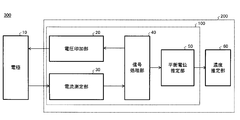
- FIG. 1 shows an example of the configuration of the equilibrium potential estimation apparatus 100.
- the equilibrium potential estimation apparatus 100 includes a voltage application unit 20, a current measurement unit 30, a signal processing unit 40, and an equilibrium potential estimation unit 50.
- the equilibrium potential estimation apparatus 100 is connected to the electrode 10 in contact with a sample (solution) containing a redox substance, and estimates the equilibrium potential of the solution.
- a solution when simply referred to as a solution, it refers to a solution for which an equilibrium potential is to be estimated.
- the electrode 10 performs an oxidation-reduction reaction with the oxidation-reduction substance contained in the solution, and exchanges electrons. Transfer of electrons is performed on the surface of the electrode 10.
- the redox substance include an oxidized mediator and a reduced mediator.
- the mediator that emits electrons becomes an oxidized mediator, and the mediator that enjoys electrons becomes a reduced mediator.
- the voltage application unit 20 applies a voltage to the electrode 10. For example, the application of a voltage to the electrode 10 is performed together with another electrode that applies a reference voltage called a reference electrode.
- the voltage application unit 20 may sweep the voltage applied to the electrode 10. Sweeping refers to changing the voltage applied to the electrode 10 with respect to time. Sweeping is not limited to linearly increasing and decreasing the voltage at a constant rate, but includes changing the voltage at an arbitrary rate of change. The sweep may also include a non-linear voltage change or a step-like voltage change in which discrete values continue.
- the current measuring unit 30 measures the current flowing through the electrode 10.
- the current measuring unit 30 transmits the measured current value to the signal processing unit 40.
- the signal processing unit 40 calculates a current integrated value of the current measured by the current measuring unit 30.
- the current integrated value is a total sum of currents that flow from when the voltage applying unit 20 applies a voltage to the electrode 10 until signal processing is performed. For example, if the total current in the direction flowing from the electrode 10 into the solution and the total current flowing in the solution from the electrode 10 are the same within the measurement period, the integrated current value becomes zero.
- the signal processing unit 40 determines a voltage condition that the voltage application unit 20 applies to the electrode 10 next.
- the reference range here may be arbitrarily changed according to the solution.
- the reference range may be a range from a predetermined value to a positive tolerance, a negative tolerance, or a positive / negative tolerance.
- the signal processing unit 40 determines whether or not the voltage applied by the voltage application unit 20 to the electrode 10 has converged when the integrated current value falls within the reference range. As a result of this determination, when it is determined that convergence has been achieved, the sweep is terminated. In addition to whether or not the voltage has converged, the signal processing unit 40 may determine whether or not the change amount of the current corresponding to the voltage sweep width is within an allowable range. .
- the determination of whether or not the amount of change in the current is within the allowable range is the absolute value of the current value observed corresponding to the voltage sweep width or the ⁇ value of the current value ( ⁇ is a real number greater than 0, and so on) ) Is within a certain range, whether the absolute value of the current value or the ⁇ value of the current value ( ⁇ is a real number smaller than 0, the same shall apply hereinafter) is outside the certain range, It is to determine whether or not the amount of change per sweep is within a certain range. That is, the determination referred to here is to determine whether or not the current is within the allowable range as a result. In the present specification, being within the reference range may include becoming the value of the reference when the width of the reference range is zero.
- the signal processing unit 40 may determine whether or not the amount of change in the integrated value of the current corresponding to the voltage sweep width is within an allowable range.
- the determination of whether or not the amount of change in the integrated value is within the allowable range is that the absolute value of the integrated value of the current observed corresponding to the voltage sweep width or the ⁇ value of the integrated value is within a certain range. Whether the absolute value of the integrated value or the ⁇ power of the integrated value is outside a certain range, and whether the amount of change per sweep of the integrated value is within a certain range. is there. That is, the determination referred to here is to determine whether or not the integrated value is within an allowable range as a result.
- the determination condition for this end is that the number of sweeps and the measurement time, such as whether the number of sweeps has reached a certain number or more, and whether the elapsed time from the measurement start time has reached a certain time or more.
- a condition based on the above may be used as the end determination condition. For example, when the number of sweeps is less than N (N is a natural number, the same shall apply hereinafter), the signal processing unit 40 determines to sweep the voltage in the direction opposite to the sweep direction in the previous sweep stage. When the number of times is N, it is determined to end the voltage sweep.
- the equilibrium potential estimation unit 50 estimates the equilibrium potential of the solution from the signal processing result of the signal processing unit 40.
- the equilibrium potential estimation unit 50 may output the estimated equilibrium potential as it is to the user. Further, the equilibrium potential estimation unit 50 may calculate the concentration of the oxidized mediator or the reduced mediator from the estimated equilibrium potential.
- FIG. 2 shows an example of the configuration of the blood sugar estimation device 300.
- the blood sugar estimation device 300 includes an electrode 10 and a concentration estimation device 200 connected to the electrode 10.
- the blood sugar estimation device 300 estimates a blood sugar level that is the concentration of glucose (glucose) in the blood.
- the blood glucose estimation device 300 is an example of a device that estimates the concentration of the redox substance from the reaction amount of the redox reaction with the electrode 10 caused by the redox substance. That is, the blood sugar estimation device 300 can similarly estimate the concentration of other solutions in addition to the blood sugar level by changing the enzyme or the like that reacts with the solution.
- An apparatus having the same configuration as that of the blood glucose estimation apparatus 300 can be used for measuring the amount of biological substances such as proteins, amino acids, and lipids, measuring the environment such as PH and harmful substances, and food inspection.
- the concentration estimation apparatus 200 includes an equilibrium potential estimation apparatus 100 and a concentration estimation unit 60.
- the concentration estimation unit 60 estimates the concentration of the solution based on the equilibrium potential estimated by the equilibrium potential estimation device 100.
- the concentration of the solution may be the concentration of the oxidized mediator or reduced mediator in the solution.
- the concentration of the solution can be calculated from the equilibrium potential using the Nernst equation.
- the Nernst equation is expressed as follows: Here, E is the equilibrium potential, E 0 is the standard electrode potential, R is the gas constant, T is the temperature (K), n is the number of mobile electrons, F is the Faraday constant, C ox is the concentration of the oxidized mediator, and C Red is Indicates the concentration of reduced mediator.
- FIG. 3 shows the concentration gradient of the reduced mediator in the solution.
- the concentration gradient is a concentration gradient with respect to the distance from the electrode 10.
- the vertical axis represents the reduced mediator concentration
- the horizontal axis represents the distance from the surface of the electrode 10.
- the concentration on the surface of the electrode 10 is referred to as surface concentration
- the concentration at a position away from the surface of the electrode 10 is referred to as bulk concentration.
- the position away from the surface of the electrode 10 is a position where the concentration of the solution is constant.
- the dotted line shows the reduced mediator concentration gradient of the ideal solution.
- the reduced mediator concentration gradient of the solution is constant regardless of the distance from the electrode 10 during measurement.
- the solid line indicates the actual concentration gradient when the electrode 10 is in contact with the solution.
- a redox reaction occurs due to the difference in electrochemical potential between the electrode 10 and the solution.
- the actual concentration gradient of the reduced mediator is different from the ideal concentration gradient of the reduced mediator.
- the equilibrium potential estimated by the equilibrium potential estimation apparatus 100 is based on the reaction at the interface between the electrode 10 and the solution, the equilibrium potential estimation apparatus 100 can actually estimate only the surface concentration of the solution. Therefore, in order to estimate the concentration of the solution more accurately, it is necessary to make the surface concentration of the solution the same as the bulk concentration of the solution.
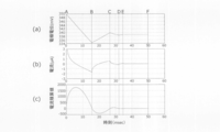
- FIG. 4 shows an example of a method for estimating the equilibrium potential.
- FIG. 4A shows the time change of the voltage applied to the electrode 10 by the voltage application unit 20.
- (B) of FIG. 4 shows the time change of the current measured by the current measuring unit 30.
- (C) of FIG. 4 shows the time change of the integrated current value calculated by the signal processing unit 40.
- the voltage application unit 20 sweeps the voltage from the initial voltage in a direction that decreases at a constant rate.
- Time A is a time during which the voltage application unit 20 applies an initial voltage to the electrode 10. If the equilibrium potential estimation method of this example is used, the equilibrium potential can be estimated for any value of the initial voltage. However, if the initial voltage is set in the vicinity of the equilibrium potential predicted from the characteristics of the solution, the estimation can be completed in a short time.
- the current measuring unit 30 detects a positive current and then detects a negative current.
- a positive current refers to a current flowing in the direction from the electrode 10 into the solution
- a negative current refers to a current flowing in a direction opposite to the positive current.
- the current measurement unit 30 measures a positive current
- an oxidation reaction occurs on the surface of the electrode 10
- the current measurement unit 30 measures a negative current a reduction reaction occurs on the surface of the electrode 10.
- the current integration value draws a mountain curve because the current is switched from positive to negative.
- Time B is the time when the integrated current value calculated by the signal processing unit 40 becomes zero.
- the time when the current integrated value becomes 0 is a turning point of the sweep speed of the applied voltage. In the present specification, the period from the return point of the sweep speed to the next return point is referred to as one cycle.
- the voltage application unit 20 applies a voltage having a reverse sweep direction to the electrode 10 in the period AB. That is, the applied voltage changes from a value smaller than the equilibrium potential of the solution to a larger value.
- the sweep speed in the period BC is controlled to half the sweep speed in the period AB.
- the current measured by the current measuring unit 30 changes from a negative value to a positive value.
- Point C is the time when the integrated current value calculated by the signal processing unit 40 becomes 0 again.
- the same cycle as the period AB and the period BC is repeated.
- the voltage applied by the voltage application unit 20 converges.
- the converged applied voltage is estimated as the equilibrium potential of the solution.
- the cycle of this example is repeated until the applied voltage converges and the equilibrium potential is estimated.
- the cycle may be repeated until a predetermined measurement time has elapsed.
- the solution used in the equilibrium potential estimation method of this example can be used again for estimation of the equilibrium potential.
- FIG. 5 shows the concentration gradient of the reduced mediator at time B in FIG.
- the vertical axis represents the reduced mediator concentration
- the horizontal axis represents the distance from the electrode 10.
- the concentration ratio according to the voltage applied to the electrode 10 is on the surface of the electrode 10. Since the voltage applied to the electrode 10 at time B is lower than the equilibrium potential of the bulk concentration, the surface concentration of the reduced mediator is higher than the bulk concentration.
- FIG. 6 shows the concentration gradient of the reduced mediator at time C in FIG.
- the difference between the voltage applied by the voltage application unit 20 to the electrode 10 and the equilibrium potential is smaller than that at time B.
- the concentration gradient of the reduced mediator is smaller in the vicinity of electrode 10 than at time B.
- FIG. 7 shows the concentration gradient of the reduced mediator at time D in FIG.
- the difference between the voltage applied by the voltage application unit 20 to the electrode 10 and the equilibrium potential is smaller than that at time C.
- the concentration gradient of the reduced mediator is smaller in the vicinity of the electrode 10 than at time C.
- FIG. 8 shows the concentration gradient of the reduced mediator at time E in FIG.
- the difference between the voltage applied by the voltage application unit 20 to the electrode 10 and the equilibrium potential is smaller than that at time D.
- the concentration gradient of the reduced mediator is smaller in the vicinity of the electrode 10 than at time D.
- FIG. 9 shows the concentration gradient of the reduced mediator at time F in FIG. At time F, the surface concentration of the reduced mediator is equal to the bulk concentration of the reduced mediator. That is, a constant reduced mediator concentration is obtained regardless of the distance from the electrode 10.
- the equilibrium potential estimation apparatus 100 eliminates the concentration gradient of the solution by controlling the voltage applied to the electrode 10. Thereby, the equilibrium potential estimation apparatus 100 can accurately estimate the equilibrium potential of the solution.
- FIG. 10 shows an example of a flowchart according to the equilibrium potential estimation method.
- the equilibrium potential estimation apparatus 100 estimates the equilibrium potential by executing steps S100 to S110.
- step S100 the signal processing unit 40 sets an initial voltage, an initial sweep speed, and an initial sweep direction. If the equilibrium potential estimation method according to the present embodiment is used, the equilibrium potential can be estimated by arbitrarily setting the initial voltage, the initial sweep speed, and the initial sweep direction. However, the time required for estimating the equilibrium potential can be shortened by setting appropriate values for the initial voltage, initial sweep speed, and initial sweep direction.
- step S101 the voltage application unit 20 applies a voltage to the electrode 10.
- step S ⁇ b> 102 the current measurement unit 30 measures the current flowing through the electrode 10.
- step S103 the signal processing unit 40 calculates an integrated current value.
- step S ⁇ b> 104 the signal processing unit 40 determines whether or not the voltage application unit 20 is sweeping in the direction of decreasing the applied voltage. When sweeping in the direction of decreasing the applied voltage, the process proceeds to step S105, and when sweeping in the direction of increasing the applied voltage, the process proceeds to step S106.
- step S105 the signal processing unit 40 determines whether or not the integrated current value is negative. If the current integrated value is negative, the process proceeds to step S107. If the current integrated value is positive, the process proceeds to step S109. On the other hand, in step S106, the signal processing unit 40 determines whether or not the current integrated value is positive. If the current integrated value is positive, the process proceeds to step S107. If the current integrated value is negative, the process proceeds to step S109.
- step S107 the signal processing unit 40 determines whether or not the variation of the applied voltage has converged. Whether or not the fluctuation of the applied voltage has converged is determined based on whether or not a predetermined voltage sweep width is within an allowable range. When it is determined that the applied voltage has converged, the process proceeds to step S110, and when it is determined that the applied voltage has not converged, the process proceeds to step S108.
- step S108 the signal processing unit 40 reverses the voltage sweep direction. Further, the signal processing unit 40 may decrease the sweep speed in step S108. As the cycle is repeated, it converges to the equilibrium potential, so the time for one cycle is shortened. Therefore, the time difference of one cycle can be reduced by reducing the sweep speed. For example, the signal processing unit 40 decreases the sweep speed at a predetermined decrease rate of the sweep speed every time step S108 is executed. In this case, the sweep speed decreases with the power of the decrease rate. Further, the signal processing unit 40 may control the sweep speed so that the time of each cycle is constant. In this way, the signal processing unit 40 changes the voltage sweep speed by estimating the equilibrium potential once, so that it becomes easier to converge to the equilibrium potential than when the sweep speed is constant. When step S108 is executed, the process proceeds to step S109.
- step S109 the voltage to be applied next is determined at the current sweep speed and sweep direction.
- the current sweep speed and sweep direction refer to the sweep speed and sweep direction set in step S108 when step S108 is executed.
- the signal processing unit 40 next determines the voltage to be applied to the electrode 10, and proceeds to step S101.
- step S110 the equilibrium potential estimation unit 50 estimates the voltage applied by the voltage application unit 20 as the equilibrium potential.
- the equilibrium potential estimation apparatus 100 may output the estimated equilibrium potential to the outside.
- the equilibrium potential estimation apparatus 100 repeats steps S101 to S109 until the applied voltage converges in step S107.
- the equilibrium potential estimation method of this example determines whether or not to reverse the sweep direction in step S108 based on the sweep direction of the applied voltage determined in step S104 and the sign of the current integrated value in steps S105 and S106. . Thereby, even when the applied voltage is swept away from the equilibrium potential, the sweep direction can be controlled to approach the equilibrium potential.
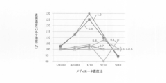
- FIG. 11 shows the dependence of the solution concentration gradient on the decrease rate of the sweep rate.
- the vertical axis represents the ratio (%) of the surface concentration to the bulk concentration of the solution, and the horizontal axis represents the mediator concentration ratio.
- Each curve shows a simulation result when the decreasing rate of the sweep rate is changed from 0.1 to 1.0.
- the sweep speed at the start of measurement is 1.0 V / sec.
- the mediator concentration ratio is a ratio of the reduced mediator to the sum of the oxidized mediator and the reduced mediator.
- the mediator concentration ratio is measured in a state where it is in an equilibrium state.
- the ratio of the surface concentration to the bulk concentration is 100 (%), it indicates that the surface concentration of the solution is equal to the bulk concentration.
- the ratio of the surface concentration to the bulk concentration is close to 100 (%) at any mediator concentration ratio.
- the rate of decrease of the sweep rate is determined based on the measurement time, mediator concentration gradient, voltage sweep cycle time, and the like. For example, the decrease rate of the sweep speed is set to a value that allows the estimation to be completed within an allowable measurement time. Further, the decrease rate of the sweep rate may be determined so that the distance from the surface of the electrode 10 that affects the solution becomes equal in one cycle of the voltage sweep. Influencing the solution means that the concentration of the solution changes due to the reaction between the electrode 10 and the solution. The distance from the electrode 10 surface that affects the solution is determined by the length of time of one cycle, the diffusion coefficient of the solution, and the like. That is, basically, the longer one cycle is, the farther it can be from the electrode 10.
- FIG. 12 shows the relationship between the decreasing rate of the sweep rate and the equilibrium potential error (mV).
- the decreasing rate of the sweep speed is changed from 0.1 to 1.0.
- the mediator concentration ratios are 1/1000, 4/1000, 1/10, 5/10 and 9/10, respectively.
- the equilibrium potential error indicates a difference from the equilibrium potential estimated from the theoretical equilibrium potential using the decrease rate of each sweep speed.
- the equilibrium potential error converges to within 0.1 mV.
- the decreasing rate of the sweep speed is 0.8 to 1.0
- the equilibrium potential error is 0.1 mV or more, and the equilibrium potential converges at a position where the concentration gradient is not eliminated.
- the decreasing rate of the sweep speed is 0.1 to 0.7
- it can be determined that the equilibrium potential error is sufficiently small.
- the sweep rate reduction rate is 0.2 to 0.7
- the equilibrium potential error is around 0 mV.
- the sweep rate of the sweep speed is 0.1 and 0.2, the sweep may be too slow to converge within the measurement time.
- the sweep rate reduction rate is preferably 0.4 or more.
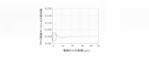
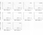
- 13 to 17 show the simulation results of the concentration gradient of the reducing substance.
- the simulation of this example is a result of changing the mediator concentration ratio in five ways. Each simulation result shows the relationship between the mediator concentration ratio and the concentration gradient after the voltage has converged.
- FIG. 13 shows the relationship between the decrease rate of the sweep rate and the concentration gradient of the reduced mediator.
- the mediator concentration ratio in this example is 1/1000.
- the reduction rate of the sweep rate and the difference in the surface concentration of the reduced mediator with respect to the bulk concentration of the reduced mediator are shown.
- the magnitude of the error of the surface concentration with respect to the bulk concentration of the reduced mediator is + 3%, + 2.5%, + 0.6%, and ⁇ 0.15, respectively.
- FIG. 14 shows the relationship between the decrease rate of the sweep rate and the concentration gradient of the reduced mediator.
- the mediator concentration ratio in this example is 4/1000.
- the magnitude of the error of the surface concentration with respect to the bulk concentration of the reduced mediator is + 12.5%, + 12.5%, + 1.25%, and ⁇ 0, respectively. 375%, -0.075%, -0.03%, -0.025%, -0.025%, -0.025%, + 2%.
- FIG. 15 shows the relationship between the decrease rate of the sweep rate and the concentration gradient of the reduced mediator.
- the mediator concentration ratio in this example is 1/10.
- the magnitude of the surface concentration error with respect to the bulk concentration of the reduced mediator is + 30%, + 25%, + 2%, + 3%, and -0.075%, respectively. , ⁇ 0.02%, ⁇ 0.012%, ⁇ 0.013%, + 0.03%, and + 4%.
- FIG. 16 shows the relationship between the decrease rate of the sweep rate and the concentration gradient of the reduced mediator.
- the mediator concentration ratio in this example is 5/10.
- the magnitude of the error of the surface concentration with respect to the bulk concentration of the reduced mediator is + 12%, + 10%, + 8%, ⁇ 0.08%, ⁇ 0, respectively.
- FIG. 17 shows the relationship between the decrease rate of the sweep rate and the concentration gradient of the reduced mediator.
- the mediator concentration ratio in this example is 9/10.
- the magnitude of the error of the surface concentration with respect to the bulk concentration of the reduced mediator is ⁇ 6.667%, ⁇ 5.556%, + 0.667%, + 0.189%, -0.0667%, -0.01333%, -0.01333%, -0.0222%, + 0.1667%, + 7.7778%.
- the range of the potential drop rate may be 0.1 to 0.8 times. More desirably, the range of the potential drop rate is 0.2 to 0.7 times. More preferably, the range of the potential drop rate is 0.4 to 0.6.
- the actually used potential drop rate may be set in consideration of the estimation time and the estimation accuracy.
- the equilibrium potential can be estimated in principle.
- the voltage converges, and the mediator concentration and the equilibrium potential may be correlated.
- the mediator concentration can be estimated by drawing a calibration curve even if the estimated equilibrium potential and the true equilibrium potential are deviated.
- FIG. 18 is a diagram for explaining a conventional constant voltage current measurement method.
- the graph shows the time change of the current value.
- 18A to 18D show the concentration of the solution with respect to the distance from the electrode 10 at each time of the electrode 10 and time a to time d.
- (A) in FIG. 18 is a schematic diagram of the solution concentration gradient at time a, which is the start of measurement. At time a, the concentration of the solution becomes uniform regardless of the distance from the electrode 10. That is, the surface concentration of the solution is equal to the bulk concentration.
- FIG. 18B is a schematic diagram of the solution concentration gradient at time b. At time b, the concentration gradually decreases from the vicinity of the electrode 10. That is, the surface concentration of the solution is lowered.
- (C) in FIG. 18 is a schematic diagram of a solution concentration gradient at time c.
- the concentration further decreases from the vicinity of the electrode 10.
- the concentration of the solution is reduced to a distance farther from the electrode 10 compared to time b. The distance at which the concentration of the solution decreases is determined depending on the diffusion coefficient of the solution.
- (D) of FIG. 18 is a schematic diagram of the solution concentration gradient at time d.
- the diffusion of the measurement substance is rate-limiting.
- the concentration of the solution is reduced to a further distance from the electrode 10 than at time c.
- the concentration is estimated from the change in the current flowing through the electrode 10.
- the change in current is the slope of the current.
- the theoretical formula of the constant voltage current measurement is as follows.
- n and F are constants
- A is an electrode area
- C is a solution concentration
- D is a diffusion coefficient
- t is time.
- the equilibrium potential estimation method has various advantages compared to the constant voltage current measurement method.
- the equilibrium potential estimation method is not affected by the electrode area compared to the constant voltage current measurement method.
- the current is proportional to the electrode area A
- high machining accuracy of the electrode is required.
- the processing accuracy of the electrode is increased using an expensive material such as gold.
- the equilibrium potential estimation method is controlled so that the integrated current value becomes zero, there is no influence by the electrode area A. That is, since the processing accuracy of the electrode 10 is not required, a material such as carbon having a rough surface can be used. Since the material cost of carbon is lower than that of materials such as gold, the manufacturing cost can be reduced.
- the equilibrium potential estimation method is not affected by the diffusion coefficient compared to the constant voltage current measurement method.
- the current changes according to the diffusion coefficient of the solution.
- the equilibrium potential estimation method is controlled so that the integrated current value becomes zero, there is no influence of the diffusion coefficient. That is, when the equilibrium potential estimation method is used, the blood glucose level can be accurately estimated regardless of the difference in diffusion coefficient caused by the individual difference of blood.
- the equilibrium potential estimation method is less affected by interfering substances than the constant voltage current measurement method.
- the interference substance is a substance that undergoes an oxidation-reduction reaction on the surface of the electrode 10 by applying a voltage to the electrode 10.
- many interfering substances are oxidized on the surface of the electrode 10, and in addition to the current due to the oxidation of the reduced mediator, the current due to the oxidizing of the interfering substance flows, and the measured current value increases, so the concentration of the solution is accurate Cannot be estimated.
- the equilibrium potential estimation method the applied voltage is lower than in the constant voltage current measurement method, and the current due to the interference substance being oxidized is small. Therefore, the equilibrium potential estimation method is less affected by the interfering substance than the constant voltage current measurement method, and can be estimated with higher accuracy.
- the equilibrium potential estimation method is a non-destructive measurement that repeats both oxidation and reduction reactions, the same solution can be repeatedly measured. That is, since the solution measured by the equilibrium potential estimation method can be measured again after a lapse of a certain time, the time change of the solution can be detected.
- the balanced potential estimation method has an advantage that the signal noise (S / N) ratio is improved and the measurement object can be made wider.
- FIG. 19 shows an example of a hardware configuration of a computer 1900 according to the present embodiment.
- a computer 1900 according to this embodiment is connected to a CPU peripheral unit having a CPU 2000, a RAM 2020, a graphic controller 2075, and a display device 2080 that are connected to each other by a host controller 2082, and to the host controller 2082 by an input / output controller 2084.
- Input / output unit having communication interface 2030, hard disk drive 2040, and CD-ROM drive 2060, and legacy input / output unit having ROM 2010, flexible disk drive 2050, and input / output chip 2070 connected to input / output controller 2084 With.
- the host controller 2082 connects the RAM 2020 to the CPU 2000 and the graphic controller 2075 that access the RAM 2020 at a high transfer rate.
- the CPU 2000 operates based on programs stored in the ROM 2010 and the RAM 2020 and controls each unit.
- the graphic controller 2075 acquires image data generated by the CPU 2000 or the like on a frame buffer provided in the RAM 2020 and displays it on the display device 2080.
- the graphic controller 2075 may include a frame buffer for storing image data generated by the CPU 2000 or the like.
- the input / output controller 2084 connects the host controller 2082 to the communication interface 2030, the hard disk drive 2040, and the CD-ROM drive 2060, which are relatively high-speed input / output devices.
- the communication interface 2030 communicates with other devices via a network.
- the hard disk drive 2040 stores programs and data used by the CPU 2000 in the computer 1900.
- the CD-ROM drive 2060 reads a program or data from the CD-ROM 2095 and provides it to the hard disk drive 2040 via the RAM 2020.
- the ROM 2010, the flexible disk drive 2050, and the relatively low-speed input / output device of the input / output chip 2070 are connected to the input / output controller 2084.
- the ROM 2010 stores a boot program that the computer 1900 executes at startup and / or a program that depends on the hardware of the computer 1900.
- the flexible disk drive 2050 reads a program or data from the flexible disk 2090 and provides it to the hard disk drive 2040 via the RAM 2020.
- the input / output chip 2070 connects the flexible disk drive 2050 to the input / output controller 2084 and inputs / outputs various input / output devices via, for example, a parallel port, a serial port, a keyboard port, a mouse port, and the like. Connect to controller 2084.
- the program provided to the hard disk drive 2040 via the RAM 2020 is stored in a recording medium such as the flexible disk 2090, the CD-ROM 2095, or an IC card and provided by the user.
- the program is read from the recording medium, installed in the hard disk drive 2040 in the computer 1900 via the RAM 2020, and executed by the CPU 2000.
- the program installed in the computer 1900 and causing the computer 1900 to function as the signal processing unit 40 includes a signal processing module. These programs or modules work on the CPU 2000 or the like to cause the computer 1900 to function as a signal processing unit.
- the information processing described in these programs functions as the signal processing unit 40, which is a specific means in which the software and the various hardware resources described above cooperate when read by the computer 1900.
- the specific signal processing part 40 according to the intended purpose is constructed
- a program installed in the computer 1900 and causing the computer 1900 to function as the concentration estimation apparatus 200 includes a voltage application module, a current measurement module, a signal processing module, an equilibrium potential estimation module, and a concentration estimation module. These programs or modules work on the CPU 2000 or the like to cause the computer 1900 to function as a concentration estimation device.
- the information processing described in these programs is read by the computer 1900, whereby the voltage application unit 20, the current measurement unit 30, the signal, which are specific means in which the software and the various hardware resources described above cooperate with each other. It functions as the processing unit 40, the equilibrium potential estimation unit 50, and the concentration estimation unit 60. And the specific density
- the CPU 2000 executes a communication program loaded on the RAM 2020 and executes a communication interface based on the processing content described in the communication program.
- a communication process is instructed to 2030.
- the communication interface 2030 reads transmission data stored in a transmission buffer area or the like provided on a storage device such as the RAM 2020, the hard disk drive 2040, the flexible disk 2090, or the CD-ROM 2095, and sends it to the network.
- the reception data transmitted or received from the network is written into a reception buffer area or the like provided on the storage device.
- the communication interface 2030 may transfer transmission / reception data to / from the storage device by a DMA (direct memory access) method. Instead, the CPU 2000 transfers the storage device or the communication interface 2030 as a transfer source.
- the transmission / reception data may be transferred by reading the data from the data and writing the data to the communication interface 2030 or the storage device of the transfer destination.
- the CPU 2000 is all or necessary from among files or databases stored in an external storage device such as a hard disk drive 2040, a CD-ROM drive 2060 (CD-ROM 2095), and a flexible disk drive 2050 (flexible disk 2090).
- This portion is read into the RAM 2020 by DMA transfer or the like, and various processes are performed on the data on the RAM 2020. Then, CPU 2000 writes the processed data back to the external storage device by DMA transfer or the like.
- the RAM 2020 and the external storage device are collectively referred to as a memory, a storage unit, or a storage device.
- the CPU 2000 can also store a part of the RAM 2020 in the cache memory and perform reading and writing on the cache memory. Even in such a form, the cache memory bears a part of the function of the RAM 2020. Therefore, in the present embodiment, the cache memory is also included in the RAM 2020, the memory, and / or the storage device unless otherwise indicated. To do.
- the CPU 2000 performs various operations, such as various operations, information processing, condition determination, information search / replacement, etc., described in the present embodiment, specified for the data read from the RAM 2020 by the instruction sequence of the program. Is written back to the RAM 2020. For example, when performing the condition determination, the CPU 2000 determines whether the various variables shown in the present embodiment satisfy the conditions such as large, small, above, below, equal, etc., compared to other variables or constants. When the condition is satisfied (or not satisfied), the program branches to a different instruction sequence or calls a subroutine.
- the CPU 2000 can search for information stored in a file or database in the storage device. For example, in the case where a plurality of entries in which the attribute value of the second attribute is associated with the attribute value of the first attribute are stored in the storage device, the CPU 2000 displays the plurality of entries stored in the storage device. The entry that matches the condition in which the attribute value of the first attribute is specified is retrieved, and the attribute value of the second attribute that is stored in the entry is read, thereby associating with the first attribute that satisfies the predetermined condition The attribute value of the specified second attribute can be obtained.
- the program or module shown above may be stored in an external recording medium.
- an optical recording medium such as DVD or CD
- a magneto-optical recording medium such as MO
- a tape medium such as an IC card, and the like
- a storage device such as a hard disk or RAM provided in a server system connected to a dedicated communication network or the Internet may be used as a recording medium, and the program may be provided to the computer 1900 via the network.
- Embodiment 1 Applying a voltage to the electrode and sweeping said voltage; A second step of measuring the current flowing through the electrode; A third stage for determining whether or not the sweep width of the voltage is within an allowable range when the integrated value of the current reaches a predetermined value; A fourth step of estimating a voltage value within the allowable range as an equilibrium potential of the redox material when determined to be within the allowable range; And a fifth stage of sweeping the voltage in a direction opposite to the sweep direction in the previous sweep stage when determined to be outside the allowable range.
- Emodiment 4 The method for estimating an equilibrium potential of a redox substance according to any one of embodiments 1 to 3, wherein in the fifth stage, the voltage is swept slower than the sweep speed in the previous sweep stage.
- Emodiment 5 The method for estimating an equilibrium potential of a redox substance according to embodiment 4, wherein the sweep speed in the fifth stage is 0.1 to 0.8 times the sweep speed in the previous sweep stage.
- Emodiment 6 The method for estimating an equilibrium potential of a redox substance according to embodiment 5, wherein the sweep speed in the fifth stage is 0.2 to 0.7 times the sweep speed in the previous sweep stage.
- a voltage application unit for applying a voltage to the electrodes; A current measuring unit for measuring a current flowing through the electrode; A signal for instructing the voltage application unit to sweep the voltage, and for determining whether or not the sweep width of the voltage is within an allowable range when the integrated value of the current reaches a predetermined value.
- a processing unit and The signal processing unit When within the allowable range, the voltage value within the allowable range is estimated as an equilibrium potential of the redox material, and when not within the allowable range, the voltage is swept in the direction opposite to the previous sweep direction. Equilibrium potential estimation device for redox substances that instructs voltage application unit.
- the signal processing unit The equilibrium of the redox material according to claim 10, wherein the voltage application unit is repeatedly instructed to sweep the voltage in a direction opposite to the previous sweep direction until the voltage sweep width falls within the allowable range.
- Potential estimation device The signal processing unit From when the integrated value of the current becomes a predetermined value until the integrated value of the current becomes a predetermined value next, the time during which the voltage is swept is constant.
- the signal processing unit The redox according to any one of embodiments 10 to 12, wherein when the voltage sweep width is not within the allowable range, the voltage application unit is instructed to sweep the voltage slower than a previous sweep speed.
- a device for estimating the equilibrium potential of a substance [Embodiment 14] The signal processing unit 14. The voltage application unit is instructed to sweep the voltage at a speed that is 0.1 to 0.8 times the previous sweep speed when the sweep width of the voltage is not within the allowable range. Equilibrium potential estimation device for redox substances.
- the signal processing unit The voltage application unit is instructed to sweep the voltage at a speed 0.2 to 0.7 times the previous sweep speed when the sweep width of the voltage is not within the allowable range.
- Equilibrium potential estimation device for redox substances The signal processing unit 16.
- the voltage application unit is instructed to sweep the voltage at a speed 0.4 to 0.6 times the previous sweep speed when the voltage sweep width is not within the allowable range.
- Equilibrium potential estimation device for redox substances The signal processing unit The apparatus for estimating an equilibrium potential of an oxidation-reduction substance according to any one of embodiments 10 to 16, wherein when the sign of the integrated value is inverted, it is determined whether a sweep width of the voltage is within an allowable range.
- An oxidation-reduction substance concentration estimation device comprising: an estimation unit that estimates the concentration of the oxidation-reduction substance based on the voltage value.
- [Embodiment 19] A program that causes a computer to function as the signal processing unit in the oxidation-reduction substance equilibrium potential estimation device according to any one of Embodiments 10 to 17.
- [Embodiment 22] A concentration-reducing apparatus for redox substances according to embodiment 18, A blood glucose
Landscapes
- Health & Medical Sciences (AREA)
- Life Sciences & Earth Sciences (AREA)
- Chemical & Material Sciences (AREA)
- Analytical Chemistry (AREA)
- Molecular Biology (AREA)
- Chemical Kinetics & Catalysis (AREA)
- Electrochemistry (AREA)
- Physics & Mathematics (AREA)
- Biochemistry (AREA)
- General Health & Medical Sciences (AREA)
- General Physics & Mathematics (AREA)
- Immunology (AREA)
- Pathology (AREA)
- Hematology (AREA)
- Biophysics (AREA)
- Investigating Or Analyzing Materials By The Use Of Electric Means (AREA)
Abstract
酸化還元物質を含有するサンプルと接触する電極に電圧を印加し、電圧を掃引する第1段階と、電極に流れる電流を測定する第2段階と、電流の積算値が基準範囲内になったときに、前の掃引段階での掃引方向と逆方向に電圧を掃引するか、電圧の掃引を終了するかを決定する第3段階と、電圧の掃引を終了すると決定したときに、電圧の値を酸化還元物質の平衡電位と推定する第4段階と、電圧を掃引すると決定したときに、前の掃引段階での掃引方向と逆方向に電圧を掃引する第5段階とを有する酸化還元物質の平衡電位推定方法を提供する。
Description
本発明は、平衡電位推定方法、平衡電位推定装置、濃度推定装置、プログラム、媒体及び血糖推定装置に関する。
従来、酸化還元物質の濃度を推定する濃度推定装置に関し、溶液に一定電圧を印加した場合に流れる電流値を測定する装置が知られている。従来の濃度推定装置は、測定した電流値の変化に基づいて、酸化還元物質の濃度を推定していた(例えば、特許文献1、2参照)。
特許文献1 特開2011-174943号公報
特許文献2 特開2013-217933号公報
特許文献1 特開2011-174943号公報
特許文献2 特開2013-217933号公報
しかしながら、従来の濃度推定装置は、測定電流値が酸化還元物質の濃度だけでなく電極の面積や溶液の拡散係数などに応じても変化してしまうため、正確な濃度を推定することができない。また、これらの課題を解決するために、溶液の開回路電圧を測定し濃度を推定する方法も知られているが、溶液と電極が接するだけで酸化還元反応が起こってしまうため、溶液の濃度に応じた電位を正確に推定することができない。
本発明の第1の態様においては、酸化還元物質を含有するサンプルと接触する電極に電圧を印加し、電圧を掃引する第1段階と、電極に流れる電流を測定する第2段階と、電流の積算値が基準範囲内になったときに、前の掃引段階での掃引方向と逆方向に電圧を掃引するか、電圧の掃引を終了するかを決定する第3段階と、電圧の掃引を終了すると決定したときに、電圧の値を酸化還元物質の平衡電位と推定する第4段階と、電圧を掃引すると決定したときに、前の掃引段階での掃引方向と逆方向に電圧を掃引する第5段階とを有する酸化還元物質の平衡電位推定方法を提供する。
本発明の第2の態様においては、酸化還元物質を含有するサンプルと接触する電極に電圧を印加する電圧印加部と、電極に流れる電流を測定する電流測定部と、電圧を掃引するよう電圧印加部に指示するとともに、電流の積算値が基準範囲内になったときに、前の掃引段階での掃引方向と逆方向に電圧を掃引するか、電圧の掃引を終了するかを決定する信号処理部とを備え、信号処理部は、電圧の掃引を終了すると決定したときに、電圧の値を酸化還元物質の平衡電位と推定し、電圧を掃引すると決定したときに、前の掃引方向と逆方向に電圧を掃引するよう電圧印加部に指示する酸化還元物質の平衡電位推定装置を提供する。
本発明の第3の態様においては、第2の態様に記載の酸化還元物質の平衡電位推定装置と、電圧値に基づいて、酸化還元物質の濃度を推定する推定部とを備える酸化還元物質の濃度推定装置を提供する。
本発明の第4の態様においては、コンピュータを、第2の態様に記載の酸化還元物質の平衡電位推定装置における信号処理部として機能させるプログラムを提供する。
本発明の第5の態様においては、第4の態様に記載のプログラムを有するコンピュータ読み取り可能な媒体を提供する。
本発明の第6の態様においては、第3の態様に記載の酸化還元物質の濃度推定装置と、電極とを備える血糖推定装置を提供する。
なお、上記の発明の概要は、本発明の特徴の全てを列挙したものではない。また、これらの特徴群のサブコンビネーションもまた、発明となりうる。
以下、発明の実施の形態を通じて本発明を説明するが、以下の実施形態は請求の範囲にかかる発明を限定するものではない。また、実施形態の中で説明されている特徴の組み合わせの全てが発明の解決手段に必須であるとは限らない。
図1は、平衡電位推定装置100の構成の一例を示す。平衡電位推定装置100は、電圧印加部20、電流測定部30、信号処理部40及び平衡電位推定部50を備える。平衡電位推定装置100は、酸化還元物質を含有するサンプル(溶液)と接触した電極10に接続し、溶液の平衡電位を推定する。本明細書において、単に溶液と称する場合、平衡電位の推定対象となる溶液を指す。
電極10は、溶液に含まれる酸化還元物質と酸化還元反応し、電子の授受を行う。電子の授受は、電極10の表面で行われる。酸化還元物質とは、例えば、酸化型メディエータ及び還元型メディエータである。電子を放出したメディエータは酸化型メディエータとなり、電子を享受したメディエータは還元型メディエータとなる。
電圧印加部20は、電極10に電圧を印加する。例えば、電極10に対する電圧の印加は、参照極と言われる基準電圧を印加する他の電極と共に行われる。電圧印加部20は、電極10に印加する電圧を掃引してもよい。掃引とは、電極10に印加する電圧を時間に対して変化させることを指す。掃引は、一定の速度で線形的に電圧を増大及び減少させることに限らず、任意の変化率で電圧を変化させることを含む。また、掃引は、非線形な電圧の変化や、離散的な値が連続する階段状の電圧の変化も含んでよい。
電流測定部30は、電極10に流れる電流を測定する。電流測定部30は、測定した電流値を信号処理部40に送信する。
信号処理部40は、電流測定部30が測定した電流の電流積算値を算出する。例えば、電流積算値とは、電圧印加部20が電極10に電圧を印加してから信号処理を行うまでに流れた電流の総和である。例えば、測定期間内において、電極10から溶液に流れ込む方向の電流の合計と、電極10から溶液に流れ出る方向の電流の合計が同じ場合、電流積算値は0になる。信号処理部40は、電流積算値が基準範囲内になったときに、次に電圧印加部20が電極10に印加する電圧の条件を決定する。ここでいう基準範囲は溶液に応じて任意に変更してもよい。基準範囲は、予め定められた値から正の許容誤差、負の許容誤差、または正負の許容誤差までの範囲であってよい。また、信号処理部40は、電流積算値が基準範囲内になったときに、電圧印加部20が電極10に印加した電圧が収束したか否かを判定する。この判定の結果、収束したと判定された場合掃引を終了する。この終了の判定の条件は電圧が収束したか否か以外にも、信号処理部40は、電圧の掃引幅に対応する電流の変化量が許容範囲内であるか否かを判定してもよい。電流の変化量が許容範囲内であるか否かの判定とは、電圧の掃引幅に対応して観測される電流値の絶対値や電流値のα乗(αは0より大きな実数、以下同じ)が一定の範囲内であるか否か、電流値の絶対値や電流値のβ乗(βは0より小さな実数、以下同じ)が一定の範囲外であるか否か、観測された電流の一掃引あたりの変化量が一定の範囲内であるか否かを判定することである。つまり、ここで言う判定とは、結果として、電流が許容範囲内に収まっているかどうかを判定することである。なお、本明細書において、基準範囲内になるとは、基準範囲の幅がゼロの場合にあっては、当該基準の値となることを含んでよい。
また、信号処理部40は、電圧の掃引幅に対応する電流の積算値の変化量が許容範囲内であるか否かを判定してもよい。積算値の変化量が許容範囲内であるか否かの判定とは、電圧の掃引幅に対応して観測される電流の積算値の絶対値や積算値のα乗が一定の範囲内であるか否か、積算値の絶対値や積算値のβ乗が一定の範囲外であるか否か、積算値の一掃引あたりの変化量が一定の範囲内であるか否かを判定することである。つまり、ここで言う判定とは、結果として、積算値が許容範囲内に収まっているかどうかを判定することである。さらに、この終了の判定条件は、掃引を実施した回数が一定回数以上に達したか否か、測定開始時刻からの経過時間が一定時間以上に達したか否かのように掃引回数や測定時間に基づく条件を終了の判定条件にしてもよい。例えば、信号処理部40は、掃引の回数がN回未満(Nは自然数、以下同じ)の場合に、前の掃引段階での掃引方向と逆方向に電圧を掃引することを決定し、掃引の回数がN回の場合に、電圧の掃引を終了することを決定する。
平衡電位推定部50は、信号処理部40の信号処理結果から溶液の平衡電位を推定する。平衡電位推定部50は、推定した平衡電位をそのままユーザーに出力してもよい。また、平衡電位推定部50は、推定した平衡電位から、酸化型メディエータ又は還元型メディエータの濃度を算出してもよい。
図2は、血糖推定装置300の構成の一例を示す。血糖推定装置300は、電極10及び電極10に接続された濃度推定装置200を備える。
血糖推定装置300は、血液内のグルコース(ブドウ糖)の濃度である血糖値を推定する。血糖推定装置300は、酸化還元物質が起こす電極10との酸化還元反応の反応量から、酸化還元物質の濃度を推定する装置の一例である。即ち、血糖推定装置300は、溶液に反応する酵素等を変更することにより、血糖値に限らず他の溶液の濃度を同様に推定できる。血糖推定装置300と同一の構成を有する装置は、タンパク質、アミノ酸、脂質などの生体物質量測定、PH、有害物質などの環境測定、及び食品検査等に用いることができる。
濃度推定装置200は、平衡電位推定装置100及び濃度推定部60を備える。濃度推定部60は、平衡電位推定装置100が推定した平衡電位に基づいて、溶液の濃度を推定する。溶液の濃度とは、溶液中の酸化型メディエータ又は還元型メディエータの濃度であってよい。溶液の濃度は、ネルンストの式を用いて平衡電位から算出できる。ネルンストの式は以下のように表される。

ここで、Eは平衡電位、E0は標準電極電位、Rは気体定数、Tは温度(K)、nは移動電子数、Fはファラデー定数、Coxは酸化型メディエータの濃度、CRedは還元型メディエータの濃度を示す。
図3は、溶液中の還元型メディエータの濃度勾配を示す。濃度勾配とは、電極10からの距離に対する濃度の傾きである。縦軸は還元型メディエータ濃度を示し、横軸は電極10の表面からの距離を示す。本明細書において、電極10表面の濃度を表面濃度と称し、電極10表面から離れた位置における濃度をバルク濃度と称する。電極10表面から離れた位置とは、溶液の濃度が一定となる位置である。
点線は、理想的な溶液の還元型メディエータ濃度勾配を示す。理想的な状態では、測定時に、溶液の還元型メディエータ濃度勾配が電極10からの距離によらず一定になる。一方、実線は、電極10が溶液に接触した場合の実際の濃度勾配を示す。実際の状態では、電極10と溶液の電気化学ポテンシャルの違いから酸化還元反応が起きる。これにより、実際の還元型メディエータの濃度勾配は、理想的な還元型メディエータの濃度勾配と異なる。
ここで、平衡電位推定装置100が推定する平衡電位は電極10と溶液との界面における反応に基づくので、平衡電位推定装置100が実際に推定できるのは溶液の表面濃度に限られる。したがって、より正確に溶液の濃度を推定するためには、溶液の表面濃度を溶液のバルク濃度と同じにする必要がある。
図4は、平衡電位を推定する方法の一例を示す。図4の(a)は、電圧印加部20が電極10に印加する電圧の時間変化を示す。図4の(b)は、電流測定部30が測定する電流の時間変化を示す。図4の(c)は、信号処理部40が算出した電流積算値の時間変化を示す。
期間A-Bにおいて、電圧印加部20は、初期電圧から電圧を一定速度で減少する方向に掃引する。時間Aは、電圧印加部20が電極10に初期電圧を印加する時間である。本例の平衡電位推定法を用いれば、初期電圧をいずれの値にとっても平衡電位を推定できる。但し、初期電圧を溶液の特性から予測される平衡電位の近傍に設定すれば、推定が短時間で済む。
期間A-Bにおいて、電流測定部30は、正の電流を検出し、その後、負の電流を検出する。正の電流とは電極10から溶液に流れ込む方向の電流を指し、負の電流とは正の電流と反対方向に流れる電流を指す。電流測定部30が正の電流を測定した場合、電極10表面では酸化反応が起こり、電流測定部30が負の電流を測定した場合、電極10表面では還元反応が起こっている。期間A-Bにおいて、電流積算値は、電流が正から負に切り替わるので、山なりの曲線を描く。時間Bは、信号処理部40が算出した電流積算値が0になる時間である。電流積算値が0になる時間は、印加電圧の掃引速度の折り返し地点となる。なお、本明細書において、掃引速度の折り返し地点から次の折り返し地点までの期間を1サイクルと称する。
期間B-Cにおいて、電圧印加部20は、期間A-Bと掃引方向が逆方向の電圧を電極10に印加する。即ち、印加電圧は、溶液の平衡電位よりも小さい値から大きい値になる。本例の期間B-Cにおける掃引速度は、期間A-Bの掃引速度の半分に制御される。電流測定部30が測定する電流は、負の値から正の値になる。点Cは、信号処理部40が算出した電流積算値が再び0になる時間である。
期間C-D及び期間D-Eでは、それぞれ期間A-B及び期間B-Cと同様のサイクルを繰り返す。これにより、時間Fでは、電圧印加部20が印加する電圧が収束する。収束した印加電圧を溶液の平衡電位と推定する。本例のサイクルは、印加電圧が収束して平衡電位が推定されるまで繰り返す。他の例では、予め定められた測定時間が経過するまでサイクルを繰り返してよい。
本例の平衡電位推定法では、電流積算値が0になるように印加電圧の掃引を制御するので、溶液中に含まれる電子の総量が初期状態と同一に保たれる。つまり、初期状態から溶液の特性を大きく変化させることなく非破壊的な測定が可能である。非破壊的な測定が可能であるため、本例の平衡電位推定法で使用した溶液は、再び平衡電位の推定に使用することができる。
図5は、図4の時間Bにおける還元型メディエータの濃度勾配を示す。縦軸は還元型メディエータ濃度を示し、横軸は電極10からの距離を示す。時間Bでは、電極10表面において、電極10に印加されている電圧に応じた濃度比になっている。時間Bで電極10に印加されている電圧は、バルク濃度の平衡電位より低いため、還元型メディエータの表面濃度がバルク濃度に比べて大きい。
図6は、図4の時間Cにおける還元型メディエータの濃度勾配を示す。時間Cでは、電圧印加部20が電極10に印加する電圧と平衡電位との差が、時間Bの場合と比較して小さい。また、時間Cでは、電極10近傍において、還元型メディエータの濃度勾配が時間Bの場合よりも小さい。
図7は、図4の時間Dにおける還元型メディエータの濃度勾配を示す。時間Dでは、電圧印加部20が電極10に印加する電圧と平衡電位との差が、時間Cの場合と比較して小さい。時間Dでは、電極10近傍において、還元型メディエータの濃度勾配が時間Cの場合よりも小さい。
図8は、図4の時間Eにおける還元型メディエータの濃度勾配を示す。時間Eでは、電圧印加部20が電極10に印加する電圧と平衡電位との差が、時間Dの場合と比較して小さい。時間Eでは、電極10近傍において、還元型メディエータの濃度勾配が時間Dの場合よりも小さい。
図9は、図4の時間Fにおける還元型メディエータの濃度勾配を示す。時間Fでは、還元型メディエータの表面濃度が、還元型メディエータのバルク濃度と等しい。即ち、電極10からの距離にかかわらず一定な還元型メディエータ濃度が得られている。
以上の通り、本実施形態に係る平衡電位推定装置100は、電極10に印加する電圧を制御することにより、溶液の濃度勾配を解消する。これにより、平衡電位推定装置100は、溶液の平衡電位を正確に推定できる。
図10は、平衡電位推定法に係るフローチャートの一例を示す。平衡電位推定装置100は、ステップS100からステップS110を実行することにより、平衡電位を推定する。
ステップS100において、信号処理部40は、初期電圧、初期掃引速度、及び初期掃引方向を設定する。本実施形態に係る平衡電位推定法を用いれば、初期電圧、初期掃引速度、及び初期掃引方向を任意に設定すれば、平衡電位を推定できる。但し、初期電圧、初期掃引速度、及び初期掃引方向をより適切な値を設定することにより、平衡電位の推定に必要な時間を短縮できる。
ステップS101において、電圧印加部20は、電極10に電圧を印加する。ステップS102において、電流測定部30は、電極10を流れる電流を測定する。
ステップS103において、信号処理部40は、電流積算値を算出する。ステップS104において、信号処理部40は、電圧印加部20が印加電圧を減少させる方向に掃引しているか否かを判定する。印加電圧を減少させる方向に掃引している場合ステップS105に進み、印加電圧を増加させる方向に掃引している場合ステップS106に進む。
ステップS105において、信号処理部40は、電流積算値が負か否かを判定する。電流積算値が負の場合ステップS107に進み、電流積算値が正の場合ステップS109に進む。一方、ステップS106において、信号処理部40は、電流積算値が正か否かを判定する。電流積算値が正の場合ステップS107に進み、電流積算値が負の場合ステップS109に進む。
ステップS107において、信号処理部40は、印加電圧の変動が収束しているか否かを判定する。印加電圧の変動が収束しているか否かは、予め定められた電圧の掃引幅が許容範囲内であるか否かに基づいて決定される。印加電圧が収束していると判定された場合ステップS110に進み、印加電圧が収束していないと判定された場合ステップS108に進む。
ステップS108において、信号処理部40は、電圧の掃引方向を逆転する。また、信号処理部40は、ステップS108において掃引速度を減少させてもよい。サイクルを重ねるにつれて平衡電位に収束していくので、1サイクルの時間が短くなる。そこで、掃引速度を減少させることにより、1サイクルの時間差を小さくできる。例えば、信号処理部40は、ステップS108を実行するごとに予め定められた掃引速度の減少率で掃引速度を減少させる。この場合、掃引速度は減少率の累乗で減少していく。また、信号処理部40は、各サイクルの時間が一定となるように掃引速度を制御してよい。このように、信号処理部40は、一回の平衡電位の推定で電圧の掃引速度を変更するので、掃引速度が一定の場合に比べて平衡電位に収束させやすくなる。ステップS108が実行されるとステップS109に進む。
ステップS109において、現在の掃引速度及び掃引方向で次に印加する電圧を決定する。現在の掃引速度及び掃引方向とは、ステップS108が実行された場合はステップS108において設定された掃引速度及び掃引方向を指す。信号処理部40は、次に電極10に印加する電圧を決定し、ステップS101に進む。
ステップS110において、平衡電位推定部50は、電圧印加部20が印加している電圧を平衡電位として推定する。平衡電位推定装置100は、推定した平衡電位を外部に出力してよい。ステップS110が実行された場合、平衡電位の推定を終了する。
平衡電位推定装置100は、ステップS107において、印加電圧が収束するまで、ステップS101からステップS109までを繰り返す。本例の平衡電位推定法は、ステップS104で判定した印加電圧の掃引方向、及び、ステップS105とステップS106における電流積算値の正負に基づき、ステップS108で掃引方向を逆転するか否かを決定する。これにより、印加電圧が平衡電位から遠ざかる方向に掃引された場合であっても、掃引方向を平衡電位に近づける方向に制御できる。
図11は、溶液の濃度勾配の掃引速度の減少率依存性を示す。縦軸は溶液のバルク濃度に対する表面濃度の比(%)を示し、横軸はメディエータ濃度比を示す。また、各曲線は、掃引速度の減少率を0.1から1.0まで変化させた場合のシミュレーション結果を示す。測定開始時の掃引速度は、1.0V/secである。なお、メディエータ濃度比とは、酸化型メディエータと還元型メディエータの和に対する還元型メディエータの比である。メディエータ濃度比は、平衡状態に落ち着いた状態で測定される。
バルク濃度に対する表面濃度の比が100(%)の場合、溶液の表面濃度が、バルク濃度と等しくなったことを示す。本例では、掃引速度の減少率が0.2~0.6の場合、いずれのメディエータ濃度比においても、バルク濃度に対する表面濃度の比が100(%)に近い値を示している。
掃引速度の減少率は、計測時間、メディエータ濃度勾配、電圧掃引のサイクル時間等に基づいて決定される。例えば、掃引速度の減少率は、許容できる計測時間内に推定を終了できるような値に設定される。また、掃引速度の減少率は、電圧掃引の1サイクルで、溶液に影響を与える電極10表面からの距離が等しくなるように決定されてよい。溶液に影響を与えるとは、電極10と溶液との反応により溶液の濃度が変化することをいう。溶液に影響を与える電極10表面からの距離は、1サイクルの時間の長さ、及び、溶液の拡散係数等によって決まる。即ち、基本的に、1サイクルの時間が長ければ長いほど、電極10から遠くまで影響を与えることができる。
図12は、掃引速度の減少率と平衡電位誤差(mV)の関係を示す。本例では、掃引速度の減少率を0.1から1.0まで変化させる。メディエータ濃度比はそれぞれ、1/1000、4/1000、1/10、5/10及び9/10である。平衡電位誤差は、理論上の平衡電位から各掃引速度の減少率を用いて推定した平衡電位との差分を示す。
例えば、1/1000のメディエータ濃度比では、掃引速度の減少率が0.1から0.7の場合、平衡電位誤差が0.1mV以内に収束する。一方、掃引速度の減少率が0.8から1.0の場合、平衡電位誤差が0.1mV以上となり、平衡電位が濃度勾配を解消しない位置で収束する。本例では、掃引速度の減少率が0.1から0.7の場合、平衡電位誤差が十分に小さいと判断できる。また、その他のメディエータ濃度比では、掃引速度の減少率が0.2から0.7の場合、平衡電位誤差が0mV付近となる。但し、掃引速度の減少率が0.1及び0.2の場合、掃引が遅すぎて計測時間内に収束しない場合がある。例えば、計測時間が1分でそれ以上の時間を打ち切りにする条件では、掃引速度の減少率を0.4以上にするのが好ましい。
図13から図17は、還元物質濃度の濃度勾配のシミュレーション結果を示す。本例のシミュレーションは、メディエータ濃度比を5通りに変化させた結果である。各シミュレーション結果は、電圧が収束した後の、メディエータ濃度比と濃度勾配の関係を示す。
図13は、掃引速度の減少率と還元型メディエータの濃度勾配の関係を示す。本例のメディエータ濃度比は1/1000である。グラフ中には、掃引速度の減少率及び還元型メディエータのバルク濃度に対する還元型メディエータの表面濃度の差を示す。減少率を1.0から0.1まで変化させた場合、還元型メディエータのバルク濃度に対する表面濃度の誤差の大きさは、それぞれ+3%、+2.5%、+0.6%、-0.15%、-0.055%、-0.035%、-0.0065%、-0.008%、-0.005%、-0.3%となる。
図14は、掃引速度の減少率と還元型メディエータの濃度勾配の関係を示す。本例のメディエータ濃度比は、4/1000である。減少率を1.0から0.1まで変化させた場合、還元型メディエータのバルク濃度に対する表面濃度の誤差の大きさは、それぞれ+12.5%、+12.5%、+1.25%、-0.375%、-0.075%、-0.03%、-0.025%、-0.025%、-0.025%、+2%となる。
図15は、掃引速度の減少率と還元型メディエータの濃度勾配の関係を示す。本例のメディエータ濃度比は、1/10である。減少率を1.0から0.1まで変化させた場合、還元型メディエータのバルク濃度に対する表面濃度の誤差の大きさは、それぞれ+30%、+25%、+2%、+3%、-0.075%、-0.02%、-0.012%、-0.013%、+0.03%、+4%となる。
図16は、掃引速度の減少率と還元型メディエータの濃度勾配の関係を示す。本例のメディエータ濃度比は、5/10である。減少率を1.0から0.1まで変化させた場合、還元型メディエータのバルク濃度に対する表面濃度の誤差の大きさは、それぞれ+12%、+10%、+8%、-0.08%、-0.04%、-0.02%、-0.01%、-0.012%、-0.16%、-10%となる。
図17は、掃引速度の減少率と還元型メディエータの濃度勾配の関係を示す。本例のメディエータ濃度比は、9/10である。減少率を1.0から0.1まで変化させた場合、還元型メディエータのバルク濃度に対する表面濃度の誤差の大きさは、それぞれ-6.667%、-5.556%、+0.667%、+0.189%、-0.0667%、-0.0133%、-0.0133%、-0.0222%、+0.1667%、+7.7778%となる。
図12から図17の結果から、電位降下速度率の範囲は0.1倍から0.8倍であってよい。より望ましくは、電位降下速度率の範囲が0.2倍から0.7倍の速度である。更に望ましくは、電位降下速度率の範囲が0.4倍から0.6倍である。実際に使用する電位降下速度率は、推定時間と推定精度を考慮して設定すればよい。
なお、電位降下速度率が1の場合であっても、原理的には平衡電位を推定できる。このように掃引速度を減少させない場合であっても電圧が収束し、メディエータ濃度と平衡電位が相関する場合がある。また、メディエータ濃度と平衡電位との間に相関が取れている場合、推定した平衡電位と真の平衡電位とがずれていても、検量線を引くことによってメディエータ濃度を推定できる。
図18は、従来技術である定電圧電流測定法を説明するための図である。グラフは電流値の時間変化を示す。図18の(a)から(d)は、電極10と時間a~時間dの各時間における、電極10からの距離に対する溶液の濃度を示す。
図18の(a)は、測定開始時である時間aの溶液濃度勾配の模式図である。時間aでは、電極10からの距離にかかわらず溶液の濃度が均一になる。即ち、溶液の表面濃度とバルク濃度が等しい。
図18の(b)は、時間bの溶液濃度勾配の模式図である。時間bでは、電極10の近傍から徐々に濃度が薄くなる。即ち、溶液の表面濃度が低下している。
図18の(c)は、時間cの溶液濃度勾配の模式図である。時間cでは、電極10の近傍からさらに濃度が薄くなる。時間cでは、時間bと比較して電極10からより遠い距離まで、溶液の濃度が薄くなる。溶液の濃度が薄くなる距離は、溶液の拡散係数に依存して決まる。
図18の(d)は、時間dの溶液濃度勾配の模式図である。時間dでは、測定物質の拡散が律速する。時間dでは、時間cよりも電極10からさらに遠い距離まで、溶液の濃度が薄くなる。
定電圧電流測定法では、電極10に流れる電流の変化から濃度を推定する。例えば、電流の変化とは電流の傾きである。ここで、定電圧電流測定の理論式は、以下の様になる。

ここで、n及びFは定数、Aは電極面積、Cは溶液濃度、Dは拡散係数、tは時間を示す。
平衡電位推定法は、定電圧電流測定法と比較して様々なメリットがある。第1に、平衡電位推定法では、定電圧電流測定法と比較して電極面積による影響を受けない。定電圧電流測定法では、電流が電極面積Aに比例するので、電極の高い加工精度が必要になる。例えば、定電圧電流測定法の測定精度を向上させるために、金などの高価な材料を用いて電極の加工精度を高める。一方、平衡電位推定法は、電流積算値が0となるように制御するので、電極面積Aによる影響がない。つまり、電極10の加工精度が必要ないため、表面の粗いカーボン等の材料を用いることができる。金などの材料と比較してカーボンの材料費が安いので製造コストを低減できる。
第2に、平衡電位推定法では、定電圧電流測定法と比較して拡散係数による影響を受けない。定電圧電流測定法では、溶液の拡散係数に応じて電流が変化する。また、血糖値を推定する場合、血液の拡散係数には個体差があるので、血糖値が同じであっても推定結果に違いが生じる。一方、平衡電位推定法は、電流積算値が0となるように制御するので、拡散係数の影響がない。即ち、平衡電位推定法を用いると、血液の個体差から生じる拡散係数の違いによらず、正確に血糖値を推定できる。
第3に、平衡電位推定法では、定電圧電流測定法と比較して干渉物質による影響が小さい。干渉物質とは電極10に電圧を印加することにより、電極10の表面で酸化還元反応する物質である。定電圧電流測定法では、電極10の表面に存在する還元型メディエータをすべて酸化させるために、高い電圧を電極10に印加する必要がある。これにより、多くの干渉物質が電極10の表面で酸化され、還元型メディエータの酸化による電流に加え、干渉物質が酸化されることによる電流が流れ、測定電流値が増加するため溶液の濃度を正確に推定することができない。一方、平衡電位推定法では、定電圧電流測定法と比較して印加する電圧が低く、干渉物質が酸化されることによる電流が少ない。そのため、平衡電位推定法では、定電圧電流測定法よりも干渉物質による影響が少なく、より精度の高い推定が可能になる。
なお、定電圧電流測定法は、酸化と還元のいずれかの反応を継続して測定する。一方、平衡電位推定法は、酸化と還元の両方の反応を繰り返す非破壊的な測定なので、同じ溶液を繰返し測定できる。つまり、平衡電位推定法により測定した溶液を、一定時間経過後再び測定できるので、溶液の時間変化を検出できる。以上の通り、平衡電位推定法は、信号ノイズ(S/N)比を向上し、測定対象をより広範囲にできるメリットがある。
図19は、本実施形態に係るコンピュータ1900のハードウェア構成の一例を示す。本実施形態に係るコンピュータ1900は、ホスト・コントローラ2082により相互に接続されるCPU2000、RAM2020、グラフィック・コントローラ2075、及び表示装置2080を有するCPU周辺部と、入出力コントローラ2084によりホスト・コントローラ2082に接続される通信インターフェイス2030、ハードディスクドライブ2040、及びCD-ROMドライブ2060を有する入出力部と、入出力コントローラ2084に接続されるROM2010、フレキシブルディスク・ドライブ2050、及び入出力チップ2070を有するレガシー入出力部とを備える。
ホスト・コントローラ2082は、RAM2020と、高い転送レートでRAM2020をアクセスするCPU2000及びグラフィック・コントローラ2075とを接続する。CPU2000は、ROM2010及びRAM2020に格納されたプログラムに基づいて動作し、各部の制御を行う。グラフィック・コントローラ2075は、CPU2000等がRAM2020内に設けたフレーム・バッファ上に生成する画像データを取得し、表示装置2080上に表示させる。これに代えて、グラフィック・コントローラ2075は、CPU2000等が生成する画像データを格納するフレーム・バッファを、内部に含んでもよい。
入出力コントローラ2084は、ホスト・コントローラ2082と、比較的高速な入出力装置である通信インターフェイス2030、ハードディスクドライブ2040、CD-ROMドライブ2060を接続する。通信インターフェイス2030は、ネットワークを介して他の装置と通信する。ハードディスクドライブ2040は、コンピュータ1900内のCPU2000が使用するプログラム及びデータを格納する。CD-ROMドライブ2060は、CD-ROM2095からプログラム又はデータを読み取り、RAM2020を介してハードディスクドライブ2040に提供する。
また、入出力コントローラ2084には、ROM2010と、フレキシブルディスク・ドライブ2050、及び入出力チップ2070の比較的低速な入出力装置とが接続される。ROM2010は、コンピュータ1900が起動時に実行するブート・プログラム、及び/又は、コンピュータ1900のハードウェアに依存するプログラム等を格納する。フレキシブルディスク・ドライブ2050は、フレキシブルディスク2090からプログラム又はデータを読み取り、RAM2020を介してハードディスクドライブ2040に提供する。入出力チップ2070は、フレキシブルディスク・ドライブ2050を入出力コントローラ2084へと接続すると共に、例えばパラレル・ポート、シリアル・ポート、キーボード・ポート、マウス・ポート等を介して各種の入出力装置を入出力コントローラ2084へと接続する。
RAM2020を介してハードディスクドライブ2040に提供されるプログラムは、フレキシブルディスク2090、CD-ROM2095、又はICカード等の記録媒体に格納されて利用者によって提供される。プログラムは、記録媒体から読み出され、RAM2020を介してコンピュータ1900内のハードディスクドライブ2040にインストールされ、CPU2000において実行される。
コンピュータ1900にインストールされ、コンピュータ1900を信号処理部40として機能させるプログラムは、信号処理モジュールを備える。これらのプログラム又はモジュールは、CPU2000等に働きかけて、コンピュータ1900を、信号処理部として機能させる。
これらのプログラムに記述された情報処理は、コンピュータ1900に読込まれることにより、ソフトウェアと上述した各種のハードウェア資源とが協働した具体的手段である信号処理部40として機能する。そして、これらの具体的手段によって、本実施形態におけるコンピュータ1900の使用目的に応じた情報の演算又は加工を実現することにより、使用目的に応じた特有の信号処理部40が構築される。
コンピュータ1900にインストールされ、コンピュータ1900を濃度推定装置200として機能させるプログラムは、電圧印加モジュールと、電流測定モジュールと、信号処理モジュールと、平衡電位推定モジュールと、濃度推定モジュールとを備える。これらのプログラム又はモジュールは、CPU2000等に働きかけて、コンピュータ1900を、濃度推定装置としてそれぞれ機能させる。
これらのプログラムに記述された情報処理は、コンピュータ1900に読込まれることにより、ソフトウェアと上述した各種のハードウェア資源とが協働した具体的手段である電圧印加部20、電流測定部30、信号処理部40、平衡電位推定部50及び濃度推定部60として機能する。そして、これらの具体的手段によって、本実施形態におけるコンピュータ1900の使用目的に応じた情報の演算又は加工を実現することにより、使用目的に応じた特有の濃度推定装置200が構築される。
一例として、コンピュータ1900と外部の装置等との間で通信を行う場合には、CPU2000は、RAM2020上にロードされた通信プログラムを実行し、通信プログラムに記述された処理内容に基づいて、通信インターフェイス2030に対して通信処理を指示する。通信インターフェイス2030は、CPU2000の制御を受けて、RAM2020、ハードディスクドライブ2040、フレキシブルディスク2090、又はCD-ROM2095等の記憶装置上に設けた送信バッファ領域等に記憶された送信データを読み出してネットワークへと送信し、もしくは、ネットワークから受信した受信データを記憶装置上に設けた受信バッファ領域等へと書き込む。このように、通信インターフェイス2030は、DMA(ダイレクト・メモリ・アクセス)方式により記憶装置との間で送受信データを転送してもよく、これに代えて、CPU2000が転送元の記憶装置又は通信インターフェイス2030からデータを読み出し、転送先の通信インターフェイス2030又は記憶装置へとデータを書き込むことにより送受信データを転送してもよい。
また、CPU2000は、ハードディスクドライブ2040、CD-ROMドライブ2060(CD-ROM2095)、フレキシブルディスク・ドライブ2050(フレキシブルディスク2090)等の外部記憶装置に格納されたファイルまたはデータベース等の中から、全部または必要な部分をDMA転送等によりRAM2020へと読み込ませ、RAM2020上のデータに対して各種の処理を行う。そして、CPU2000は、処理を終えたデータを、DMA転送等により外部記憶装置へと書き戻す。このような処理において、RAM2020は、外部記憶装置の内容を一時的に保持するものとみなせるから、本実施形態においてはRAM2020および外部記憶装置等をメモリ、記憶部、または記憶装置等と総称する。本実施形態における各種のプログラム、データ、テーブル、データベース等の各種の情報は、このような記憶装置上に格納されて、情報処理の対象となる。なお、CPU2000は、RAM2020の一部をキャッシュメモリに保持し、キャッシュメモリ上で読み書きを行うこともできる。このような形態においても、キャッシュメモリはRAM2020の機能の一部を担うから、本実施形態においては、区別して示す場合を除き、キャッシュメモリもRAM2020、メモリ、及び/又は記憶装置に含まれるものとする。
また、CPU2000は、RAM2020から読み出したデータに対して、プログラムの命令列により指定された、本実施形態中に記載した各種の演算、情報の加工、条件判断、情報の検索・置換等を含む各種の処理を行い、RAM2020へと書き戻す。例えば、CPU2000は、条件判断を行う場合においては、本実施形態において示した各種の変数が、他の変数または定数と比較して、大きい、小さい、以上、以下、等しい等の条件を満たすかどうかを判断し、条件が成立した場合(又は不成立であった場合)に、異なる命令列へと分岐し、またはサブルーチンを呼び出す。
また、CPU2000は、記憶装置内のファイルまたはデータベース等に格納された情報を検索することができる。例えば、第1属性の属性値に対し第2属性の属性値がそれぞれ対応付けられた複数のエントリが記憶装置に格納されている場合において、CPU2000は、記憶装置に格納されている複数のエントリの中から第1属性の属性値が指定された条件と一致するエントリを検索し、そのエントリに格納されている第2属性の属性値を読み出すことにより、所定の条件を満たす第1属性に対応付けられた第2属性の属性値を得ることができる。
また、請求の範囲、明細書、および図面中において示した装置、システム、プログラム、および方法における動作、手順、ステップ、および段階等の各処理の実行順序は、特段「より前に」、「先立って」等と明示しておらず、また、前の処理の出力を後の処理で用いるのでない限り、任意の順序で実現しうることに留意すべきである。請求の範囲、明細書、および図面中の動作フローに関して、便宜上「まず、」、「次に、」等を用いて説明したとしても、この順で実施することが必須であることを意味するものではない。
以上に示したプログラム又はモジュールは、外部の記録媒体に格納されてもよい。記録媒体としては、フレキシブルディスク2090、CD-ROM2095の他に、DVD又はCD等の光学記録媒体、MO等の光磁気記録媒体、テープ媒体、ICカード等の半導体メモリ等を用いることができる。また、専用通信ネットワーク又はインターネットに接続されたサーバシステムに設けたハードディスク又はRAM等の記憶装置を記録媒体として使用し、ネットワークを介してプログラムをコンピュータ1900に提供してもよい。
以下、本発明の実施態様を示す。
[実施態様1]
電極に電圧を印加し、前記電圧を掃引する第1段階と、
前記電極に流れる電流を測定する第2段階と、
前記電流の積算値が予め定められた値になったときに、前記電圧の掃引幅が許容範囲内であるか否かを判定する第3段階と、
前記許容範囲内と判定した場合に、前記許容範囲内の電圧値を酸化還元物質の平衡電位と推定する第4段階と、
前記許容範囲外と判定した場合に、前の掃引段階での掃引方向と逆方向に前記電圧を掃引する第5段階と
を有する酸化還元物質の平衡電位推定方法。
[実施態様2]
前記電圧の掃引幅を前記許容範囲内と判定するまで、前記第3段階と前記第5段階とを繰り返し実行する実施態様1に記載の酸化還元物質の平衡電位推定方法。
[実施態様3]
前記電流の積算値が予め定められた値になったときから、次に前記電流の積算値が予め定められた値になるまでに、前記電圧を掃引している時間が一定となるように、前記電圧の掃引速度を調整する実施態様1または2に記載の酸化還元物質の平衡電位推定方法。
[実施態様4]
前記第5段階では、前の掃引段階での掃引速度よりも遅く前記電圧を掃引する実施態様1から3のいずれか一項に記載の酸化還元物質の平衡電位推定方法。
[実施態様5]
前記第5段階での掃引速度は、前の掃引段階での掃引速度の0.1倍から0.8倍の速度である実施態様4に記載の酸化還元物質の平衡電位推定方法。
[実施態様6]
前記第5段階での掃引速度は、前の掃引段階での掃引速度の0.2倍から0.7倍の速度である実施態様5に記載の酸化還元物質の平衡電位推定方法。
[実施態様7]
前記第5段階での掃引速度は、前の掃引段階での掃引速度の0.4倍から0.6倍の速度である実施態様6に記載の酸化還元物質の平衡電位推定方法。
[実施態様8]
前記第3段階では、前記積算値の符号が反転したときに、前記電圧の掃引幅が前記許容範囲内であるか否かを判定する
実施態様1から7のいずれか一項に記載の酸化還元物質の平衡電位推定方法。
[実施態様9]
実施態様1から8のいずれか一項に記載の酸化還元物質の平衡電位推定方法における前記第1段階から前記第5段階と、
前記電圧値に基づいて、前記酸化還元物質の濃度を推定する第6段階と
を有する酸化還元物質の濃度推定方法。
[実施態様10]
電極に電圧を印加する電圧印加部と、
前記電極に流れる電流を測定する電流測定部と、
前記電圧を掃引するよう前記電圧印加部に指示するとともに、前記電流の積算値が予め定められた値になったときに、前記電圧の掃引幅が許容範囲内であるか否かを判定する信号処理部と
を備え、
前記信号処理部は、
前記許容範囲内であるときに、前記許容範囲内の電圧値を酸化還元物質の平衡電位と推定し、前記許容範囲内でないときに、前の掃引方向と逆方向に前記電圧を掃引するよう前記電圧印加部に指示する
酸化還元物質の平衡電位推定装置。
[実施態様11]
前記信号処理部は、
前記電圧の掃引幅が、前記許容範囲内となるまで、前の掃引方向と逆方向に前記電圧を掃引するよう前記電圧印加部に指示することを繰り返す
実施態様10に記載の酸化還元物質の平衡電位推定装置。
[実施態様12]
前記信号処理部は、
前記電流の積算値が予め定められた値になったときから、次に前記電流の積算値が予め定められた値になるまでに、前記電圧を掃引している時間が一定となるように、前記電圧の掃引速度を調整する
実施態様11に記載の酸化還元物質の平衡電位推定装置。
[実施態様13]
前記信号処理部は、
前記電圧の掃引幅が、前記許容範囲内でないときに、前の掃引速度よりも遅く前記電圧を掃引するよう前記電圧印加部に指示する
実施態様10から12のいずれか一項に記載の酸化還元物質の平衡電位推定装置。
[実施態様14]
前記信号処理部は、
前記電圧の掃引幅が、前記許容範囲内でないときに、前の掃引速度の0.1倍から0.8倍の速度で前記電圧を掃引するよう前記電圧印加部に指示する
実施態様13に記載の酸化還元物質の平衡電位推定装置。
[実施態様15]
前記信号処理部は、
前記電圧の掃引幅が、前記許容範囲内でないときに、前の掃引速度の0.2倍から0.7倍の速度で前記電圧を掃引するよう前記電圧印加部に指示する
実施態様14に記載の酸化還元物質の平衡電位推定装置。
[実施態様16]
前記信号処理部は、
前記電圧の掃引幅が、前記許容範囲内でないときに、前の掃引速度の0.4倍から0.6倍の速度で前記電圧を掃引するよう前記電圧印加部に指示する
実施態様15に記載の酸化還元物質の平衡電位推定装置。
[実施態様17]
前記信号処理部は、
前記積算値の符号が反転したときに、前記電圧の掃引幅が許容範囲内であるか否かを判定する
実施態様10から16のいずれか一項に記載の酸化還元物質の平衡電位推定装置。
[実施態様18]
実施態様10から17のいずれか一項に記載の酸化還元物質の平衡電位推定装置と、
前記電圧値に基づいて、前記酸化還元物質の濃度を推定する推定部と
を備える酸化還元物質の濃度推定装置。
[実施態様19]
コンピュータを、実施態様10から17のいずれか一項に記載の酸化還元物質の平衡電位推定装置における前記信号処理部として機能させるプログラム。
[実施態様20]
コンピュータを、実施態様18に記載の酸化還元物質の濃度推定装置における前記信号処理部及び前記推定部として機能させるプログラム。
[実施態様21]
実施態様19または20に記載のプログラムを有するコンピュータ読み取り可能な媒体。
[実施態様22]
実施態様18に記載の酸化還元物質の濃度推定装置と、
前記電極と
を備える血糖推定装置。
以上、本発明を実施の形態を用いて説明したが、本発明の技術的範囲は上記実施の形態に記載の範囲には限定されない。上記実施の形態に、多様な変更または改良を加えることが可能であることが当業者に明らかである。その様な変更または改良を加えた形態も本発明の技術的範囲に含まれ得ることが、請求の範囲の記載から明らかである。
請求の範囲、明細書、および図面中において示した装置、システム、プログラム、および方法における動作、手順、ステップ、および段階等の各処理の実行順序は、特段「より前に」、「先立って」等と明示しておらず、また、前の処理の出力を後の処理で用いるのでない限り、任意の順序で実現しうることに留意すべきである。請求の範囲、明細書、および図面中の動作フローに関して、便宜上「まず、」、「次に、」等を用いて説明したとしても、この順で実施することが必須であることを意味するものではない。
10・・・電極、20・・・電圧印加部、30・・・電流測定部、40・・・信号処理部、50・・・平衡電位推定部、60・・・濃度推定部、100・・・平衡電位推定装置、200・・・濃度推定装置、300・・・血糖推定装置、1900・・・コンピュータ、2000・・・CPU、2010・・・ROM、2020・・・RAM、2030・・・通信インターフェイス、2040・・・ハードディスクドライブ、2050・・・フレキシブルディスク・ドライブ、2060・・・CD-ROMドライブ、2070・・・入出力チップ、2075・・・グラフィック・コントローラ、2080・・・表示装置、2082・・・ホスト・コントローラ、2084・・・入出力コントローラ、2090・・・フレキシブルディスク、2095・・・CD-ROM
Claims (26)
- 酸化還元物質を含有するサンプルと接触する電極に電圧を印加し、前記電圧を掃引する第1段階と、
前記電極に流れる電流を測定する第2段階と、
前記電流の積算値が基準範囲内になったときに、前の掃引段階での掃引方向と逆方向に前記電圧を掃引するか、前記電圧の掃引を終了するかを決定する第3段階と、
前記電圧の掃引を終了すると決定したときに、前記電圧の値を酸化還元物質の平衡電位と推定する第4段階と、
前記電圧を掃引すると決定したときに、前の掃引段階での掃引方向と逆方向に前記電圧を掃引する第5段階と
を有する酸化還元物質の平衡電位推定方法。 - 前記第3段階では、前記電流の積算値が前記基準範囲内になったときに、前記電圧の掃引幅、前記掃引幅に対応する前記電流の変化量、または前記掃引幅に対応する前記積算値の変化量が許容範囲内であるか否かを判定し、
前記第4段階では、前記許容範囲内であると判定した場合に、前記許容範囲内の電圧値を前記平衡電位と推定し、
前記第5段階では、前記許容範囲外であると判定した場合に、前の掃引段階での掃引方向と逆方向に前記電圧を掃引する
請求項1に記載の酸化還元物質の平衡電位推定方法。 - 前記第3段階では、前記掃引の回数がN回未満(Nは自然数、以下同じ)の場合に、前の掃引段階での掃引方向と逆方向に前記電圧を掃引することを決定し、前記掃引の回数がN回の場合に、前記電圧の掃引を終了することを決定し、
前記第4段階では、前記掃引の回数がN回の場合に、前記電圧の値を前記平衡電位と推定し、
前記第5段階では、前記掃引の回数がN回未満の場合に、前の掃引段階での掃引方向と逆方向に前記電圧を掃引する
請求項1に記載の酸化還元物質の平衡電位推定方法。 - 前記電圧の掃引幅、前記掃引幅に対応する前記電流の変化量、または前記掃引幅に対応する前記積算値の変化量を前記許容範囲内と判定するまで、前記第3段階と前記第5段階とを繰り返し実行する請求項2に記載の酸化還元物質の平衡電位推定方法。
- 前記電流の積算値が前記基準範囲内になったときから、次に前記電流の積算値が前記基準範囲内になるまでに、前記電圧を掃引している時間が一定となるように、前記電圧の掃引速度を調整する請求項1から4のいずれか一項に記載の酸化還元物質の平衡電位推定方法。
- 前記第5段階では、前の掃引段階での掃引速度よりも遅く前記電圧を掃引する請求項1から5のいずれか一項に記載の酸化還元物質の平衡電位推定方法。
- 前記第5段階での掃引速度は、前の掃引段階での掃引速度の0.1倍から0.8倍の速度である請求項6に記載の酸化還元物質の平衡電位推定方法。
- 前記第5段階での掃引速度は、前の掃引段階での掃引速度の0.2倍から0.7倍の速度である請求項7に記載の酸化還元物質の平衡電位推定方法。
- 前記第5段階での掃引速度は、前の掃引段階での掃引速度の0.4倍から0.6倍の速度である請求項8に記載の酸化還元物質の平衡電位推定方法。
- 前記第3段階では、前記積算値の符号が反転したときに、前記電圧の掃引を終了するかどうかを決定する
請求項2に記載の酸化還元物質の平衡電位推定方法。 - 請求項2に記載の酸化還元物質の平衡電位推定方法における前記第1段階から前記第5段階と、
前記電圧値に基づいて、前記酸化還元物質の濃度を推定する第6段階と
を有する酸化還元物質の濃度推定方法。 - 酸化還元物質を含有するサンプルと接触する電極に電圧を印加する電圧印加部と、
前記電極に流れる電流を測定する電流測定部と、
前記電圧を掃引するよう前記電圧印加部に指示するとともに、前記電流の積算値が基準範囲内になったときに、前の掃引段階での掃引方向と逆方向に前記電圧を掃引するか、前記電圧の掃引を終了するかを決定する信号処理部と
を備え、
前記信号処理部は、
前記電圧の掃引を終了すると決定したときに、前記電圧の値を酸化還元物質の平衡電位と推定し、前記電圧を掃引すると決定したときに、前の掃引方向と逆方向に前記電圧を掃引するよう前記電圧印加部に指示する
酸化還元物質の平衡電位推定装置。 - 前記信号処理部は、
前記電流の積算値が前記基準範囲内になったときに、前記電圧の掃引幅、前記掃引幅に対応する前記電流の変化量、または前記掃引幅に対応する前記積算値の変化量が許容範囲内であるか否かを判定し、
前記許容範囲内であると判定した場合に、前記許容範囲内の電圧値を前記平衡電位と推定し、前記許容範囲外であると判定した場合に、前の掃引段階での掃引方向と逆方向に前記電圧を掃引する
請求項12に記載の酸化還元物質の平衡電位推定装置。 - 前記信号処理部は、
前記掃引の回数がN回未満(Nは自然数、以下同じ)の場合に、前の掃引段階での掃引方向と逆方向に前記電圧を掃引し、
前記掃引の回数がN回の場合に、前記電圧の掃引を終了し、前記電圧の値を前記平衡電位と推定する
請求項12に記載の酸化還元物質の平衡電位推定装置。 - 前記信号処理部は、
前記電圧の掃引幅、前記掃引幅に対応する前記電流の変化量、または前記掃引幅に対応する前記積算値の変化量が、前記許容範囲内となるまで、前の掃引方向と逆方向に前記電圧を掃引するよう前記電圧印加部に指示することを繰り返す
請求項13に記載の酸化還元物質の平衡電位推定装置。 - 前記信号処理部は、
前記電流の積算値が前記基準範囲内になったときから、次に前記電流の積算値が前記基準範囲内になるまでに、前記電圧を掃引している時間が一定となるように、前記電圧の掃引速度を調整する
請求項13に記載の酸化還元物質の平衡電位推定装置。 - 前記信号処理部は、
前記電圧の掃引幅が、前記許容範囲内でないときに、前の掃引速度よりも遅く前記電圧を掃引するよう前記電圧印加部に指示する
請求項13に記載の酸化還元物質の平衡電位推定装置。 - 前記信号処理部は、
前記電圧の掃引幅が、前記許容範囲内でないときに、前の掃引速度の0.1倍から0.8倍の速度で前記電圧を掃引するよう前記電圧印加部に指示する
請求項17に記載の酸化還元物質の平衡電位推定装置。 - 前記信号処理部は、
前記電圧の掃引幅が、前記許容範囲内でないときに、前の掃引速度の0.2倍から0.7倍の速度で前記電圧を掃引するよう前記電圧印加部に指示する
請求項18に記載の酸化還元物質の平衡電位推定装置。 - 前記信号処理部は、
前記電圧の掃引幅が、前記許容範囲内でないときに、前の掃引速度の0.4倍から0.6倍の速度で前記電圧を掃引するよう前記電圧印加部に指示する
請求項19に記載の酸化還元物質の平衡電位推定装置。 - 前記信号処理部は、
前記積算値の符号が反転したときに、前記電圧の掃引を終了するかどうかを決定する
請求項12から20のいずれか一項に記載の酸化還元物質の平衡電位推定装置。 - 請求項12から21のいずれか一項に記載の酸化還元物質の平衡電位推定装置と、
前記電圧の値に基づいて、前記酸化還元物質の濃度を推定する推定部と
を備える酸化還元物質の濃度推定装置。 - コンピュータを、請求項12から21のいずれか一項に記載の酸化還元物質の平衡電位推定装置における前記信号処理部として機能させるプログラム。
- コンピュータを、請求項22に記載の酸化還元物質の濃度推定装置における前記信号処理部及び前記推定部として機能させるプログラム。
- 請求項23または24に記載のプログラムを有するコンピュータ読み取り可能な媒体。
- 請求項22に記載の酸化還元物質の濃度推定装置と、
前記電極と
を備える血糖推定装置。
Priority Applications (4)
| Application Number | Priority Date | Filing Date | Title |
|---|---|---|---|
| EP15859251.9A EP3206024B1 (en) | 2014-11-12 | 2015-11-06 | Equilibrium potential estimation method, equilibrium potential estimation device, concentration estimation device, and blood-sugar estimation device |
| CN201580061752.1A CN107110820B (zh) | 2014-11-12 | 2015-11-06 | 平衡电位估计方法、平衡电位估计装置、浓度估计装置、程序、介质以及血糖估计装置 |
| JP2016559024A JP6371408B2 (ja) | 2014-11-12 | 2015-11-06 | 平衡電位推定方法、平衡電位推定装置、濃度推定装置、プログラム、媒体及び血糖推定装置 |
| US15/593,343 US10641730B2 (en) | 2014-11-12 | 2017-05-12 | Equilibrium potential estimating method, equilibrium potential estimating device, concentration estimating device, program, medium and blood sugar estimating device |
Applications Claiming Priority (2)
| Application Number | Priority Date | Filing Date | Title |
|---|---|---|---|
| JP2014-229614 | 2014-11-12 | ||
| JP2014229614 | 2014-11-12 |
Related Child Applications (1)
| Application Number | Title | Priority Date | Filing Date |
|---|---|---|---|
| US15/593,343 Continuation US10641730B2 (en) | 2014-11-12 | 2017-05-12 | Equilibrium potential estimating method, equilibrium potential estimating device, concentration estimating device, program, medium and blood sugar estimating device |
Publications (1)
| Publication Number | Publication Date |
|---|---|
| WO2016076232A1 true WO2016076232A1 (ja) | 2016-05-19 |
Family
ID=55954319
Family Applications (1)
| Application Number | Title | Priority Date | Filing Date |
|---|---|---|---|
| PCT/JP2015/081363 WO2016076232A1 (ja) | 2014-11-12 | 2015-11-06 | 平衡電位推定方法、平衡電位推定装置、濃度推定装置、プログラム、媒体及び血糖推定装置 |
Country Status (5)
| Country | Link |
|---|---|
| US (1) | US10641730B2 (ja) |
| EP (1) | EP3206024B1 (ja) |
| JP (1) | JP6371408B2 (ja) |
| CN (1) | CN107110820B (ja) |
| WO (1) | WO2016076232A1 (ja) |
Citations (3)
| Publication number | Priority date | Publication date | Assignee | Title |
|---|---|---|---|---|
| JPS5852556A (ja) * | 1981-09-24 | 1983-03-28 | Terumo Corp | イオン選択透過膜およびイオンセンサ− |
| JPH0240551A (ja) * | 1988-08-01 | 1990-02-09 | Jonan Kagaku Sangyo Kk | 電極電解洗浄法 |
| JPH06148138A (ja) * | 1992-11-02 | 1994-05-27 | Mitsui Eng & Shipbuild Co Ltd | 電量分析法 |
Family Cites Families (6)
| Publication number | Priority date | Publication date | Assignee | Title |
|---|---|---|---|---|
| US20100000881A1 (en) * | 2003-10-30 | 2010-01-07 | North Carolina State University | Electrochemical detection of nucleic acid hybridization |
| CN1635371A (zh) * | 2003-12-26 | 2005-07-06 | 财团法人工业技术研究院 | 利用脉冲伏安法侦测微量物质的方法 |
| EP1751533A2 (en) * | 2004-05-14 | 2007-02-14 | Bayer Healthcare, LLC | Voltammetric systems for assaying biological analytes |
| US8404100B2 (en) | 2005-09-30 | 2013-03-26 | Bayer Healthcare Llc | Gated voltammetry |
| SG10201403559UA (en) * | 2011-02-28 | 2014-10-30 | Aytu Bioscience Inc | Method and apparatus for measuring oxidation-reduction potential |
| WO2014025044A1 (ja) * | 2012-08-10 | 2014-02-13 | 国立大学法人豊橋技術科学大学 | 酸化還元電位の測定装置及び測定方法 |
-
2015
- 2015-11-06 CN CN201580061752.1A patent/CN107110820B/zh active Active
- 2015-11-06 WO PCT/JP2015/081363 patent/WO2016076232A1/ja active Application Filing
- 2015-11-06 EP EP15859251.9A patent/EP3206024B1/en active Active
- 2015-11-06 JP JP2016559024A patent/JP6371408B2/ja active Active
-
2017
- 2017-05-12 US US15/593,343 patent/US10641730B2/en active Active
Patent Citations (3)
| Publication number | Priority date | Publication date | Assignee | Title |
|---|---|---|---|---|
| JPS5852556A (ja) * | 1981-09-24 | 1983-03-28 | Terumo Corp | イオン選択透過膜およびイオンセンサ− |
| JPH0240551A (ja) * | 1988-08-01 | 1990-02-09 | Jonan Kagaku Sangyo Kk | 電極電解洗浄法 |
| JPH06148138A (ja) * | 1992-11-02 | 1994-05-27 | Mitsui Eng & Shipbuild Co Ltd | 電量分析法 |
Non-Patent Citations (2)
| Title |
|---|
| AKIRA FUJISHIMA ET AL.: "Denki Kagaku Sokuteiho (Jo)", GIHODO SHUPPAN CO. LTD, 15 November 1984 (1984-11-15), pages 145 - 148, XP008185659 * |
| BOBACKA J ET AL.: "Equilibrium potential of potentiometric ion sensors under steady-state current by using current-reversal chronopotentiometry.", J ELECTROANAL CHEM, vol. 509, no. 1, 10 August 2001 (2001-08-10), pages 27 - 30, XP055376915 * |
Also Published As
| Publication number | Publication date |
|---|---|
| EP3206024A4 (en) | 2017-11-01 |
| CN107110820B (zh) | 2019-05-07 |
| JPWO2016076232A1 (ja) | 2017-08-17 |
| EP3206024B1 (en) | 2020-01-08 |
| US10641730B2 (en) | 2020-05-05 |
| JP6371408B2 (ja) | 2018-08-08 |
| US20170248545A1 (en) | 2017-08-31 |
| CN107110820A (zh) | 2017-08-29 |
| EP3206024A1 (en) | 2017-08-16 |
Similar Documents
| Publication | Publication Date | Title |
|---|---|---|
| JP4381413B2 (ja) | バイオセンサー・システム | |
| JP5039062B2 (ja) | バイオセンサー系における温度補正被分析物決定 | |
| TWI468679B (zh) | 決定樣本中之待測物濃度的方法及使用該方法的手持式測量裝置和生物感測器系統 | |
| KR102142647B1 (ko) | 인공신경망 딥러닝 기법을 활용한 측정물 분석 방법, 장치, 학습 방법 및 시스템 | |
| Nowotny et al. | Precision and accuracy of blood glucose measurements using three different instruments | |
| Westgard et al. | Assessing quality on the Sigma scale from proficiency testing and external quality assessment surveys | |
| JP2017151118A (ja) | 既使用で乾燥したセンサを検出するシステム及び方法 | |
| JP2009510434A5 (ja) | ||
| KR20070027527A (ko) | 바이오센서용 임계치 기반 보정 함수의 실행방법 및 이를위한 장치 | |
| AU2017219171A1 (en) | Extrapolation of interpolated sensor data to increase sample throughput | |
| Toumazou et al. | A new era of semiconductor genetics using ion-sensitive field-effect transistors: the gene-sensitive integrated cell | |
| JP6371408B2 (ja) | 平衡電位推定方法、平衡電位推定装置、濃度推定装置、プログラム、媒体及び血糖推定装置 | |
| KR20170028408A (ko) | 분석물 농도 측정 | |
| JPWO2006046538A1 (ja) | 血液試料における特定成分の濃度測定方法および濃度測定装置 | |
| Hardeman et al. | Test 1 analyser for determination of ESR. 1. Practical evaluation and comparison with the Westergren technique | |
| TWI464397B (zh) | 生物感測器、感測單元與方法 | |
| JP2005514593A (ja) | 流体中の溶存酸素を決定するためのシステムおよび方法 | |
| Rollborn et al. | Analysis of HbA1c on an automated multicapillary zone electrophoresis system | |
| JP2019132705A (ja) | 電気化学測定方法、電気化学測定装置、プログラムおよびコンピュータ可読記録媒体 | |
| JP2009164538A (ja) | 閾値電圧演算方法、閾値電圧演算プログラムおよび閾値電圧演算装置 | |
| US8620590B2 (en) | Dose surface method for determination of analyte ratios | |
| WO2022137272A1 (ja) | 計測装置及び計測方法 | |
| JP2010193832A (ja) | 遺伝子解析方法および遺伝子解析システム | |
| TW201202692A (en) | Measurement device and measurement method utilizing the same | |
| Dong et al. | Ensuring fair assessment of solid-state nanopore sensors with reporting baseline current |
Legal Events
| Date | Code | Title | Description |
|---|---|---|---|
| 121 | Ep: the epo has been informed by wipo that ep was designated in this application |
Ref document number: 15859251 Country of ref document: EP Kind code of ref document: A1 |
|
| ENP | Entry into the national phase |
Ref document number: 2016559024 Country of ref document: JP Kind code of ref document: A |
|
| NENP | Non-entry into the national phase |
Ref country code: DE |
|
| REEP | Request for entry into the european phase |
Ref document number: 2015859251 Country of ref document: EP |