WO2016072085A1 - 通信システム、1台以上のサーバ、および1台以上のサーバ用のプログラム - Google Patents
通信システム、1台以上のサーバ、および1台以上のサーバ用のプログラム Download PDFInfo
- Publication number
- WO2016072085A1 WO2016072085A1 PCT/JP2015/005505 JP2015005505W WO2016072085A1 WO 2016072085 A1 WO2016072085 A1 WO 2016072085A1 JP 2015005505 W JP2015005505 W JP 2015005505W WO 2016072085 A1 WO2016072085 A1 WO 2016072085A1
- Authority
- WO
- WIPO (PCT)
- Prior art keywords
- vehicle
- request
- state
- cloud
- data block
- Prior art date
- Legal status (The legal status is an assumption and is not a legal conclusion. Google has not performed a legal analysis and makes no representation as to the accuracy of the status listed.)
- Ceased
Links
Images








Classifications
-
- B—PERFORMING OPERATIONS; TRANSPORTING
- B60—VEHICLES IN GENERAL
- B60H—ARRANGEMENTS OF HEATING, COOLING, VENTILATING OR OTHER AIR-TREATING DEVICES SPECIALLY ADAPTED FOR PASSENGER OR GOODS SPACES OF VEHICLES
- B60H1/00—Heating, cooling or ventilating devices
- B60H1/22—Heating, cooling or ventilating devices the heat source being other than the propulsion plant
-
- F—MECHANICAL ENGINEERING; LIGHTING; HEATING; WEAPONS; BLASTING
- F24—HEATING; RANGES; VENTILATING
- F24F—AIR-CONDITIONING; AIR-HUMIDIFICATION; VENTILATION; USE OF AIR CURRENTS FOR SCREENING
- F24F11/00—Control or safety arrangements
- F24F11/89—Arrangement or mounting of control or safety devices
-
- B—PERFORMING OPERATIONS; TRANSPORTING
- B60—VEHICLES IN GENERAL
- B60R—VEHICLES, VEHICLE FITTINGS, OR VEHICLE PARTS, NOT OTHERWISE PROVIDED FOR
- B60R16/00—Electric or fluid circuits specially adapted for vehicles and not otherwise provided for; Arrangement of elements of electric or fluid circuits specially adapted for vehicles and not otherwise provided for
- B60R16/02—Electric or fluid circuits specially adapted for vehicles and not otherwise provided for; Arrangement of elements of electric or fluid circuits specially adapted for vehicles and not otherwise provided for electric constitutive elements
-
- F—MECHANICAL ENGINEERING; LIGHTING; HEATING; WEAPONS; BLASTING
- F25—REFRIGERATION OR COOLING; COMBINED HEATING AND REFRIGERATION SYSTEMS; HEAT PUMP SYSTEMS; MANUFACTURE OR STORAGE OF ICE; LIQUEFACTION SOLIDIFICATION OF GASES
- F25B—REFRIGERATION MACHINES, PLANTS OR SYSTEMS; COMBINED HEATING AND REFRIGERATION SYSTEMS; HEAT PUMP SYSTEMS
- F25B49/00—Arrangement or mounting of control or safety devices
- F25B49/02—Arrangement or mounting of control or safety devices for compression type machines, plants or systems
-
- H—ELECTRICITY
- H04—ELECTRIC COMMUNICATION TECHNIQUE
- H04Q—SELECTING
- H04Q9/00—Arrangements in telecontrol or telemetry systems for selectively calling a substation from a main station, in which substation desired apparatus is selected for applying a control signal thereto or for obtaining measured values therefrom
Definitions
- the present disclosure relates to a communication system, one or more servers, and a program for one or more servers.
- a technique for detecting that the amount of refrigerant in a vehicle air conditioner is insufficient is known.
- a control device that controls a vehicle air conditioner controls a compressor of the air conditioner to determine a lack of refrigerant in the vehicle air conditioner.
- the software for determining the refrigerant shortage describes the process of controlling the on-vehicle actuator called the compressor, so the data size is larger than that of the diagnostic software that does not control the on-vehicle actuator. It tends to be. Therefore, as in Patent Document 1, if software for determining the lack of refrigerant is added to the control device, the memory capacity of the control device increases relatively, which reduces the size and cost of the control device. Hinder.
- the inventor pays attention to the ease of communication between the vehicle and the server (or server group) outside the vehicle, and causes the server (or server group) outside the vehicle to make a refrigerant shortage determination of the vehicle air conditioner.
- the server (or server group) outside the vehicle to make a refrigerant shortage determination of the vehicle air conditioner.
- This new technology was further examined, and it was considered that real-time determination was necessary for effective determination of refrigerant shortage by a server (or server group) outside the vehicle.
- the determination of real-time characteristics is not limited to the determination of refrigerant shortage, but applies to all techniques for diagnosing an in-vehicle device by controlling an in-vehicle actuator.
- Real-time performance refers to the amount of vehicle operating status at a certain point in time, transmitted to a server (or server group) via communication, and reflected as control in the vehicle through a refrigerant inspection process at the server (or server group). This means that the operation to be performed is performed periodically by a scheduled time.
- the delay due to communication between the vehicle and the server (or server group) is small, the real-time property is good. However, if the delay is large, it becomes difficult to reflect control until a predetermined time. That is, the real-time property is poor, and there is a high possibility that appropriate diagnosis (for example, refrigerant shortage determination) cannot be performed.
- the delay is the sum of the time for processing data on the vehicle side and the server side and the time related to communication.
- This disclosure is intended to add a real-time determination to a technology that causes one or more servers outside the vehicle to diagnose an in-vehicle device (for example, a refrigerant shortage determination of a vehicle air conditioner).
- an in-vehicle device for example, a refrigerant shortage determination of a vehicle air conditioner.
- a communication system is mounted on a vehicle together with an in-vehicle device, and obtains and transmits inspection data necessary for diagnosing the in-vehicle device;
- One or more servers that are installed outside the vehicle, receive inspection data transmitted by the control device, and use the received inspection data to control an actuator mounted on the vehicle, thereby diagnosing the in-vehicle device;
- the control device or one or more servers determine whether the time required for communication between the control device and the one or more servers exceeds a predetermined standard, and the one or more servers are required for communication The diagnosis is stopped based on the determination that the time exceeds the predetermined standard.
- one or more servers communicate with a control device that acquires and transmits inspection data necessary for diagnosing the in-vehicle device mounted on the vehicle together with the in-vehicle device, Provided to be installed outside the vehicle. Further, the server receives the inspection data transmitted by the control device, and uses the received inspection data to control an actuator mounted on the vehicle, thereby diagnosing the in-vehicle device, and one control device.
- a determination unit that determines whether or not a time required for communication with the server exceeds a predetermined reference. The inspection unit stops diagnosis based on the determination unit determining that the time required for communication exceeds a predetermined reference.
- the program is installed in the vehicle together with the in-vehicle device, communicates with a control device that acquires and transmits inspection data necessary for diagnosing the in-vehicle device, and is installed outside the vehicle.
- a control device that acquires and transmits inspection data necessary for diagnosing the in-vehicle device, and is installed outside the vehicle.
- the program receives an inspection data transmitted by the control device from one or more servers, and uses the received inspection data to control an actuator mounted on the vehicle to perform an inspection unit that diagnoses the in-vehicle device.
- a function of a determination unit that determines whether the time required for communication between the control device and one or more servers exceeds a predetermined standard.
- the inspection unit stops diagnosis based on the determination unit determining that the time required for communication exceeds a predetermined reference.
- the real-time determination is realized in such a way that the diagnosis of the in-vehicle device is stopped. Yes. Thereby, it is possible to reduce the waste of continuing diagnosis until there is a high possibility that proper diagnosis cannot be performed due to poor real-time performance.
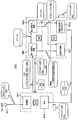
- the communication system of this embodiment includes an in-vehicle system 100 installed in a vehicle and a cloud 200 (one or more servers installed in a remote place outside the vehicle and communicating with the in-vehicle system 100). Corresponding to an example).
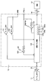
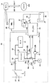
- the in-vehicle system 100 includes an engine 1, a compressor 2, a condenser 3, an expansion valve 4, an evaporator 5, an A / C magnet clutch 6, a water temperature sensor 7, a refrigerant pressure sensor 8, an evaporator fin temperature sensor 9, a vehicle speed sensor 10, and air conditioning electronic control.
- a unit (A / C_ECU) 11, a cloud-compatible air conditioning panel 12, and a wireless converter 13 are included.
- Engine 1 is a well-known engine that generates a driving force for driving a vehicle on which the in-vehicle system 100 is mounted.
- the compressor 2, the condenser 3, the expansion valve 4, and the evaporator 5 constitute a known refrigeration cycle for adjusting the temperature of the blown air blown into the vehicle interior.
- the compressor 2, the condenser 3, the expansion valve 4, the evaporator 5, the A / C magnet clutch 6, the refrigerant pressure sensor 8, the evaporator fin temperature sensor 9, and the A / C_ECU 11 are well-known vehicle air conditioners (an example of an in-vehicle device). Corresponding).
- the compressor 2 is an actuator that draws in refrigerant, compresses it, and discharges it.
- the compressor 2 operates by obtaining power from the engine 1 via the A / C magnet clutch 6. Transmission of power from the engine 1 to the compressor 2 by the A / C magnet clutch 6 is controlled by a compressor drive request CMP output from the A / C_ECU 17 to the A / C magnet clutch 6.
- the refrigerant inlet side of the condenser 3 that condenses the refrigerant is connected to the discharge side of the compressor 2.
- the refrigerant outlet side of the condenser 3 is connected to the refrigerant inlet side of the expansion valve 4 that decompresses and expands the refrigerant.
- the refrigerant inlet side of the evaporator 5 is connected to the refrigerant outlet side of the expansion valve 4.
- the evaporator 5 is arrange
- the refrigerant suction side of the compressor 2 is connected to the refrigerant outlet side of the evaporator 5.
- the water temperature sensor 7 is a sensor that detects the temperature THW of the cooling water of the engine 1.
- the refrigerant pressure sensor 8 is a sensor that detects a refrigerant pressure PRE between the refrigerant discharge side of the compressor 2 and the refrigerant inlet side of the condenser 3.
- the evaporator fin temperature sensor 9 is a sensor that detects the temperature TEfin of the outer surface (fin) of the evaporator 5.
- the vehicle speed sensor 10 is a sensor that detects a traveling speed SPD of a vehicle on which the in-vehicle system 100 is mounted.
- the A / C_ECU 11 obtains the ignition state IG of the vehicle, obtains detection signals (THW, PRE, TEfin, SPD) from the sensors 7 to 10, and obtains a data block X described later from the cloud-compatible air conditioning panel 12. get. And A / C_ECU11 communicates with the cloud corresponding
- the A / C_ECU 11 can be realized by, for example, a known microcomputer having a CPU, a memory such as a ROM and a RAM, an input / output unit, and the like.
- the cloud-compatible air conditioning panel 12 is arranged on the vehicle interior side surface portion at the center of the dashboard of the vehicle, and includes a plurality of switches 121 and 122 that can be operated by a vehicle occupant and indicators 123 and 124 that can be visually recognized by the vehicle occupant. Contains.
- the cloud-compatible air conditioning panel 12 includes an air conditioning panel control device 125 in addition to the A / C switch 121, the OFF switch 122, the A / C display 123, and the refrigerant shortage display 124 described above. Yes.
- the A / C switch 121 and the OFF switch 122 are members that are pressed by a vehicle occupant, and the air-conditioning panel control device 125 can detect whether the switches 121 and 122 are pressed.
- the A / C indicator 123 is an LED for notifying the occupant that the compressor 2 is operating, and is switched on and off according to the control of the air conditioning panel control device 125.
- the refrigerant shortage indicator 124 is an LED for notifying the occupant that the refrigerant in the refrigeration cycle of the vehicle air conditioner is insufficient, and is switched on and off according to the control of the air conditioning panel control device 125.
- the air conditioning panel control device 125 is a computer that controls the lighting and extinguishing of the indicators 123 and 124.
- the air conditioning panel control device 125 receives the data block W from the A / C_ECU 11 and transmits the data block X to the A / C_ECU 11 via the in-vehicle LAN 15 (for example, CAN (Controller Area Network, registered trademark)). Further, the air conditioning panel control device 125 executes the communication process 125d, thereby receiving the data block Z from the wireless converter 13 via the in-vehicle communication line 16 (for example, a serial communication line) and the data block Y to the wireless converter 13 Send to.
- the in-vehicle communication line 16 for example, a serial communication line
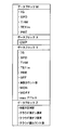
- the data block W includes an ignition state IG, a vehicle speed SPD, a cooling water temperature THW, an evaporator fin temperature TEfin, and a refrigerant pressure PRE. These data constitute refrigerant inspection data necessary for determining the lack of refrigerant in the vehicle air conditioner.
- the A / C_ECU 11 repeats the data block W including the latest values of the ignition state IG, the vehicle speed SPD, the cooling water temperature THW, the evaporator fin temperature TEfin, and the refrigerant pressure PRE periodically and specifically (specifically in a cycle of 1 second). It transmits to the air-conditioning panel control apparatus 125 via the in-vehicle communication line 16.
- Data block X includes a compressor drive request CMP.
- the air conditioning panel control device 125 transmits the data block X including the latest compressor drive request CMP to the A / C_ECU 11 repeatedly and periodically (for example, every second).
- the A / C_ECU 11 controls the operation and non-operation of the compressor 2 by outputting the received compressor drive request CMP to the A / C magnet clutch 6.
- the data block Y includes, in addition to the above-mentioned data IG, SPD, THW, TEfin, PRE, data OFF indicating whether or not the OFF switch 122 is pressed, a manual-on request MON, a manual-off request MOFF, and a vehicle side count value described later. (Vehicle-side real-time confirmation count value) is included. These constitute the refrigerant inspection data necessary for determining the refrigerant shortage of the vehicle air conditioner.
- the air-conditioning panel control device 125 repeatedly and periodically (specifically, in a 1-second cycle) creates a data block Y including the data IG, SPD, THW, TEfin, PRE, data OFF, and the latest value of the vehicle side count value.
- the manual-on request MON and the manual-off request MOFF are so-called event data that is included in the data block Y and transmitted by the air conditioning panel control device 125 only when a specific condition is satisfied.
- the data other than the data clearly indicating the event data is so-called level data.
- Level data is transmitted every cycle, whereas event data is transmitted only when a specific condition is satisfied.
- the wireless converter 13 adds its own address (for example, MAC address) to the data block Y received from the air conditioning panel control device 125 (see FIG. 3), and information on the data block Y to which its own address is added. Is transmitted to the modem 14 by a known wireless communication method (for example, wireless LAN, Bluetooth (registered trademark)).
- a known wireless communication method for example, wireless LAN, Bluetooth (registered trademark)
- the modem 14 is a device such as a cellular phone, for example, and is a device that can be carried by a passenger in the vehicle and brought into the vehicle interior to communicate with the wireless converter 13 and the cloud 200 that is a group of servers installed outside the vehicle. .
- the modem 14 transmits the data block Y received from the wireless converter 13 to the cloud 200.
- the modem 14 and the cloud 200 communicate via a wide area network such as the Internet.
- the modem 14 repeatedly receives the data block Z from the cloud 200.
- the data block Z includes four pieces of data such as a refrigerant shortage determination, a cloud departure on request, a cloud departure off request, and a cloud side count value.
- the cloud-on request (corresponding to an example of a remote request) is event data indicating that the operation start of the compressor 2 is requested from the cloud 200 side for the refrigerant shortage determination.
- the cloud-off request (corresponding to an example of a remote request) is event data indicating that the operation stop of the compressor 2 is requested from the cloud 200 side for the refrigerant shortage determination.
- the cloud side count value will be described later.
- the cloud 200 transmits the data block Z including the latest refrigerant shortage determination and the cloud-side count value to the modem 14 repeatedly and periodically, specifically in a cycle of 1 second. Further, the cloud origin on request and the cloud origin off request, which are event data, are included in the data block Z only when a specific condition is satisfied.
- the modem 14 transmits the received data block Z to the wireless converter 13, and the wireless converter 13 transmits the received data block Z to the air conditioning panel control device 125.
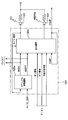
- the air conditioning panel control device 125 is configured to execute a manual state transition process 125a, an output arbitration process 125b, a count return process 125c, and a communication process 125d in parallel.
- the manual state transition process 125a is performed when the A / C switch 121 is pressed when the A / C display 123 output from the output arbitration process 125b is turned on or off.
- This is a process for determining whether or not an ON request MON and a manual OFF request MOFF are generated.
- the manual on request MON is event data indicating that the occupant has manually requested the start of operation of the compressor
- the manual off request MOFF is event data indicating that the occupant has manually requested the operation of the compressor to be stopped.
- the air-conditioning panel control device 125 generates a manual-on request MON when the A / C switch 121 is pressed in the manual state transition process 125a when the A / C display 123 is turned off. To do. If the A / C switch 121 is pressed while the A / C display 123 is lit, a manual off request MOFF is generated. The generated manual-on request MON or manual-off request MOFF is passed only once from the manual state transition process 125a to the output arbitration process 125b and included in the data block Y to be transmitted next.
- the output arbitration process 125b is a process for determining whether to turn on the A / C display 123 and whether to output the data block X including the compressor drive request CMP to the A / C_ECU 11.
- the decision is made based on whether or not there is a manual on request MON and a manual off request MOFF. Further, the determination is made based on the presence / absence of a cloud origin on request and a cloud origin off request in the latest data block Z.
- the cloud origin on request and the cloud origin off request are also event data.
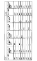
- the operation of the air conditioning panel control device 125 in the output mediation processing 125b is specifically as shown in FIG.
- a case will be described in which the A / C display 123 is turned off and the value of the compressor drive request CMP that is finally transmitted to the A / C_ECU 11 is OFF.
- the manual on request MON is passed from the manual state transition processing 125a
- the A / C display 123 is turned on, and the data block X including the compressor driving request CMP having an ON value is output to the A / C_ECU 11. .
- the A / C display 123 is turned on and the value of the compressor drive request CMP transmitted to the A / C_ECU 11 at the end is ON will be described.
- the manual off request MOFF is passed from the manual state transition process 125a
- the A / C display 123 is turned off, and the data block X including the compressor drive request CMP having an off value is output to the A / C_ECU 11. .
- the A / C display 123 is turned on and the value of the compressor drive request CMP transmitted to the A / C_ECU 11 at the end is OFF will be described.
- the A / C display 123 is turned off and a data block X including the compressor drive request CMP having an ON value is output to the A / C_ECU 11. .
- the A / C display 123 is turned off and the value of the compressor drive request CMP transmitted to the A / C_ECU 11 at the end is OFF will be described.
- the A / C display 123 is left off and the data block X including the compressor drive request CMP having an ON value is displayed. Is output to the A / C_ECU 11.
- the A / C_ECU 11 immediately outputs the compressor drive request CMP having an ON value to the A / C magnet clutch 6, so that the compressor 2 starts an operation for determining whether the refrigerant is insufficient.
- the reason why the A / C display 123 is kept off is that it is not always necessary to notify the occupant that the compressor 2 is temporarily operated for the refrigerant shortage determination.
- the A / C display 123 is turned on and the value of the compressor drive request CMP transmitted to the A / C_ECU 11 at the end is ON will be described.
- the A / C display 123 is kept lit, and the data block X including the compressor drive request CMP with an off value is included. Is output to the A / C_ECU 11.
- the A / C_ECU 11 immediately outputs the compressor drive request CMP having an off value to the A / C magnet clutch 6, and the operation for the refrigerant shortage determination by the compressor 2 is stopped.
- the A / C display 123 is kept lit from the viewpoint that it is not always necessary to notify the occupant that the compressor 2 is temporarily stopped for the refrigerant shortage determination.
- the compressor is temporarily set for the refrigerant shortage determination.
- the A / C display 123 is turned off and the value of the compressor drive request CMP transmitted to the A / C_ECU 11 is on, that is, the compressor is temporarily set for the refrigerant shortage determination.
- the compressor is temporarily set for the refrigerant shortage determination.
- the A / C display 123 is left off and the data block X including the compressor drive request CMP having an ON value is displayed. Is output to the A / C_ECU 11.
- the A / C_ECU 11 immediately outputs the compressor drive request CMP having an ON value to the A / C magnet clutch 6, so that the operation for the refrigerant shortage determination by the compressor 2 continues.
- the compressor is temporarily used for refrigerant shortage determination.
- a case where 2 is stopped will be described.
- the A / C display 123 is kept lit, and the data block X including the compressor drive request CMP with an off value is included. Is output to the A / C_ECU 11.
- the A / C_ECU 11 immediately outputs the compressor drive request CMP having an off value to the A / C magnet clutch 6, so that the compressor 2 continues to be stopped.
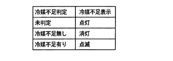
- the air conditioning panel control device 125 further controls turning on / off of the refrigerant shortage indicator 124 based on the latest refrigerant shortage determination included in the data block Z, as shown in FIG. . Specifically, if the latest refrigerant shortage determination value is “not determined”, the refrigerant shortage indicator 124 is continuously lit, and if the value is “no refrigerant shortage”, the refrigerant shortage indicator 124 is turned off. If the value is “the refrigerant is insufficient”, the refrigerant shortage indicator 124 is blinked.
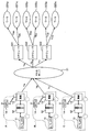
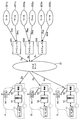
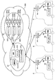
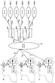
- the cloud 200 includes a master server 21 and a slave server group 22.
- the slave server group 22 includes a plurality of job schedulers 221, 222, and 223.
- the slave server group 22 further includes a plurality of workers 221p and 221q managed by the job scheduler 221, a plurality of workers 222p and 222q managed by the job scheduler 222, and a plurality of workers 223p and 223q managed by the job scheduler 223. have.
- the in-vehicle system 100 and the modem 14 shown in FIG. 1 are mounted on each of the plurality of vehicles A, B, and C, and the wireless conversion that the cloud-compatible air conditioning panel 12 of each of the in-vehicle systems 100 is mounted on the same vehicle. It communicates with the master server 21 via the device 13 and the modem 14.
- These servers 21, 221, 222, 223, 221p, 221q, 222p, 222q, 223p, and 223q may each be realized as separate personal computers (or workstations) that can communicate with each other. Alternatively, some of these servers may be realized in the same personal computer (or workstation). Since the hardware configuration of a plurality of personal computers (or workstations) for realizing these servers is well known, description thereof is omitted here.
- the master server 21 is configured to execute a calculation instruction process 21a and has a storage medium (not shown), and a refrigerant inspection program 21b, a count program 21c, and a real time determination program 21d are recorded on the storage medium. .
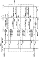
- FIG. 9 illustrates a data exchange procedure in the communication system having the configuration shown in FIG. The operation of the entire communication system will be described with reference to this figure.
- the operations of the master server 21 described below are all operations realized by the master server 21 executing the calculation instruction process 21a.
- the A / C_ECU 11 updates the data of the ignition state IG from off to on. Thereafter, at the transmission timing of the first data block W to be visited, the A / C_ECU 11 sends the data block W including the latest values of the ignition state IG, the vehicle speed SPD, the coolant temperature THW, the evaporator fin temperature TEfin, and the refrigerant pressure PRE to the in-vehicle communication. It transmits to the air-conditioning panel control apparatus 125 via the line 16 (communication 301).
- the air conditioning panel control device 125 transmits the data IG, SPD, THW, TEfin, PRE included in the data block W to the data block for transmission at the transmission timing of the data block Y that first visits after receiving the data block W. Include in Y.
- the air conditioning panel control device 125 also includes it in the data block Y for transmission this time. However, since the notification of completion of control preparation has not been received from the master server 21 after the vehicle ignition is turned on, based on this, the data block Y of this time does not include the data OFF and the vehicle side count value. . And the air-conditioning panel control apparatus 125 transmits this data block Y to the master server 21 via the wireless converter 13 and the modem 14 (communication 303). At this time, the wireless converter 13 adds its own address to the data block Y. In FIG. 9, Ya is written to clearly indicate that the data block Y is from the vehicle A.
- the master server 21 that has received the data block Ya has the value of the data IG included in the received data block Ya on, and is included in the data block Y that was previously transmitted from the address included in the data block Ya. Based on the value of the data IG being off, one job scheduler 221 is selected for the vehicle A from the plurality of job schedulers, and the refrigerant inspection program 21b, count is selected for the selected job scheduler 221 for the vehicle A.
- the program 21c and the real-time property determination program 21d are transmitted (communication 305).
- the job scheduler 221 Upon receiving these programs 21b, 21c, and 21d, the job scheduler 221 transmits a notification of completion of control preparation to the master server 21 (communication 307).
- the master server 21 transmits this control preparation completion notification to the address (the address of the wireless converter 13 of the vehicle A) (communication 309).
- the A / C_ECU 11 of the vehicle A receives this control preparation completion notification via the modem 14 and the wireless converter 13.
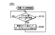
- the air conditioning panel control device 125 starts executing the flowchart of the count return processing 125c shown in FIG. Thereby, the preparation for the refrigerant shortage determination in the refrigeration cycle of the vehicle air conditioner of the vehicle A is completed.
- the described flowchart includes a plurality of sections (or referred to as steps), and each section is expressed as, for example, S110.
- each section can be divided into multiple subsections, while multiple sections can be combined to function as a single section, or the entire flowchart can function as a single section. It is.
- Each section can be referred to as a device, a module.
- the section includes (i) not only a section of software combined with a hardware unit (eg, a computer) but also (ii) a section of hardware (eg, an integrated circuit, a wiring logic circuit) and related devices. It can be realized with or without the function.
- the hardware section can be included inside the microcomputer.
- the A / C_ECU 11 of the vehicle A controls the air-conditioning panel of the vehicle A with the data block W including the latest values of the data IG, SPD, THW, TEfin, PRE at the next transmission timing of the regular data block W. It transmits to the apparatus 125 (communication 311).
- the air conditioning panel control device 125 receives this data block W, and transmits the data IG, SPD, THW, TEfin, and PRE included in the data block W at the transmission timing of the data block Y that comes first after that. Include in credit data block Y.
- the air conditioning panel control device 125 also includes it in the data block Y for transmission this time.
- the air conditioning panel control device 125 includes data OFF indicating whether or not the OFF switch 122 is pressed in the data block Y based on the fact that the control preparation completion notification has already been received. Further, in the process of FIG. 10, the air conditioning panel control device 125 repeats S110 without executing S120 by determining that the cloud-side count value is not newly received in S110. Therefore, the vehicle side count value is not included in the data block Y.
- the air conditioning panel control device 125 transmits such a data block Y (denoted as Ya in FIG. 9) to the master server 21 via the wireless converter 13 and the modem 14 (communication 313). At this time, the wireless converter 13 adds its own address to the data block Y.
- the data block Y having the same configuration (denoted as Yb and Yc in FIG. 9) is transmitted to the master server 21 (communication). 315, 317)
- the data block Yb, Yc may include a vehicle-side count value.
- the master server 21 selects the job schedulers 222 and 223 for the vehicle B and the vehicle C from the plurality of job schedulers, respectively, and the refrigerant inspection program 21b, A count program 21c and a real-time property determination program 21d are transmitted.
- the master server 21 that has received the data block Ya transmits a job request communication including the data block Ya to the job scheduler 221 (communication 319).
- the job scheduler 221 that has received this job request communication performs the processing specified by the programs 21b, 21c, and 21d based on the contents of the data block Ya included in the job request communication and the processing contents of the programs 21b, 21c, and 21d.
- the calculation requests Yap and Yaq include the contents of processing to be performed by each of the workers 221p and 221q and data necessary for the processing (the contents of the latest data block Ya).
- the processing of the programs 21b, 21c, and 21d to be performed on the vehicle A is appropriately distributed and assigned to the plurality of workers 221p and 221q by the job scheduler 221, thereby reducing the processing load on each worker.
- the technology of such distributed processing is well known.
- the technology of Windows (registered trademark) Windows_HPC_Server (Windows is a registered trademark) may be used, or Mathworks (registered trademark) Parallel Computing Toolbox. The technique may be used.
- FIG. 11 shows a data flow from the vehicle A to the workers 221p and 221q as described above.
- the vehicle B and the cloud 200 communicate with the master server 21, the job scheduler 222, the worker 222p, and the worker 222q with the same operation as the vehicle A and the cloud 200.
- the vehicle C and the cloud 200 also communicate with the master server 21, the job scheduler 223, the worker 223p, and the worker 223q with the same operation as the vehicle A and the cloud 200.
- the workers 221p and 221q perform operations according to the calculation requests Yap and Yaq from the job scheduler 221, respectively, and transmit the calculation results Zap and Zaq obtained as a result of the operations to the job scheduler 221 (communication 323).
- the refrigerant shortage determination, the cloud departure on request, the cloud departure off request, and the cloud side count value are included in any of the calculation results Zap and Zaq.
- real-time values (NG, OK) and various variables used at the time of calculation are included in the calculation results Zap and Zaq.
- the job scheduler 221 that has received the calculation results Zap and Zaq immediately transmits the calculation results to each of the plurality of workers 221p and 221q managed by the own machine (that is, with a delay sufficiently shorter than 1 second). In this way, the values of various data are consistent among the plurality of workers 221p and 221q managed by the same job scheduler 221.
- the job scheduler 221 extracts a refrigerant shortage determination, a cloud departure on request (if any), a cloud departure off request (if any), and a cloud-side count value from the latest received calculation results Zap and Zaq, and a data block Z (denoted as Za in FIG. 9) is generated, and job result communication including this data block Za is repeatedly and regularly transmitted to the master server 21 (specifically, in a cycle of 1 second) (communication 325).
- the cloud-compatible air conditioning panel 12 receives the data block Za via the modem 14 and the wireless converter 13. Then, the air conditioning panel control device 125 turns on / off / flashes the refrigerant shortage indicator 124 as shown in FIG. 7 based on the refrigerant shortage determination value included in the received data block Za in the output arbitration process 125b. To control.
- the air conditioning panel control device 125 determines whether or not each of the cloud departure on request and the cloud departure off request is included in the received data block Za in the output arbitration processing 125b, as shown in FIG.
- the lighting / extinguishing of the A / C display 123 is controlled to determine the value (on / off) of the compressor drive request CMP.
- the determined compressor drive request CMP value is included in the data block X and transmitted to the A / C_ECU 11 (communication 329).
- the A / C_ECU 11 controls the operation of the compressor 2 by outputting the compressor drive request CMP in the data block X received from the cloud-compatible air conditioning panel 12 to the A / C magnet clutch 6.
- FIG. 12 shows the data flow from the workers 221p and 221q to the vehicle A as described above.
- the vehicle B and the cloud 200 communicate with the master server 21, the job scheduler 222, the worker 222p, and the worker 222q with the same operation as the vehicle A and the cloud 200.
- the vehicle C and the cloud 200 also communicate with the master server 21, the job scheduler 223, the worker 223p, and the worker 223q with the same operation as the vehicle A and the cloud 200.
- processing similar to the processing from the ignition on of the vehicle A described above until the control of the operation of the compressor 2 by the A / C_ECU 11 is basically performed. Is repeated periodically (specifically, with a period of one second).
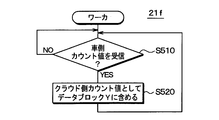
- the cloud-compatible air conditioning panel 12 determines that the cloud-side count value is newly received in S110 of FIG. Then, the process proceeds to S120.
- S120 the same value as the newly received cloud-side count value is set as the vehicle-side count value and included in the data block Y. Accordingly, at this time, the data block Y (communication 337) transmitted from the cloud-compatible air conditioning panel 12 to the master server 21 via the wireless converter 13 and the modem 14 has the same value as the cloud-side count value received immediately before. Side count value is included.
- the subsequent communication 337, 339, 341, 343, 345, 347, 349, 351, 353, 355, 357 is performed in accordance with the communication 313, 315, 317, 319, 321, 323, 325, 327, 329, 331. 333, and the type of data to be transmitted is also the same. However, the data value itself changes according to the processing result of the worker and the in-vehicle system 100.
- the refrigerant inspection program 21b is a program for refrigerant inspection processing for determining whether or not the refrigerant in the refrigeration cycle of the vehicle is insufficient.
- the refrigerant inspection program 21b defines four states SX, SA, SB, and SC.
- the state SX is a state at the start of program execution, that is, a start state.
- State SA is a state in which the refrigerant shortage determination has not been performed, stopped, or canceled.
- the state SB is a state in the middle of the refrigerant shortage determination.
- State SC is a state in which the refrigerant shortage determination is completed.
- the state SA includes an unexecuted state SA1 and a canceled state SA2 as lower layers.
- the state SB includes the first determination under stop state SB1 and the second determination under stop state SB2 as lower layers.
- the state SC includes a refrigerant shortage state SC1 and a refrigerant shortage state SC2 as lower layers.
- the values of data IG, SPD, THW, TEfin, PRE, OFF, MON, MOFF used for the determination are the data blocks Ya during the latest job request communication received by the job scheduler 221 from the master server 21. Determine by reference.
- the state of execution of the refrigerant inspection program 21b (workers 221p and 221q in this example) is the initial state SZ.
- the execution subject detects that the IG has changed from OFF to ON while in the start state SZ, the execution subject transitions to the unexecuted state SA1 of the state SA.
- the execution subject performs the operation G3. That is, the counters J and K are cleared to zero, and the refrigerant shortage determination value is set to “not determined”.
- the state SA (including the unexecuted state SA1 and the stop state SA2), if the real-time property is determined to be NG (defective), the state SA remains.
- the real time property is determined in the processing of the real time property determination program 21d described later.
- condition S1 is a condition that the real-time property changes from NG to OK (good), and all of the following conditions (1) to (3) are satisfied for 300 seconds or more.
- the manual off request MOFF has never been received since the manual on request MON was last received.
- SPD is 0 km / h.
- (3) THW exceeds 45 degrees C.
- the above condition (1) is satisfied when the compressor 2 is operated for 300 seconds or more after the A / C switch 121 is operated by the user.
- the value of the refrigerant shortage determination is set to “not determined” and the value of the counter J is incremented by 1 every 1 second, and the data block Za transmitted next time from the master server 21.
- the cloud-on request is included in the data block Z and transmitted to the air conditioning panel control device 125.
- the air conditioning panel control device 125 turns on the compressor drive request CMP as shown in FIG. 6 in the output arbitration process 125b, so that the compressor 2 continues to be driven by the A / C_ECU 11 during the state SB1.
- state SB1 when the value of counter J exceeds 16, the state transitions to state SB2.
- state SB1 when the value of PRE exceeds the refrigerant shortage 50% inspection pressure, the state transitions to state SC1 in state SC.
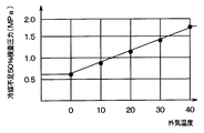
- the refrigerant shortage 50% inspection pressure may be a predetermined constant value (for example, 1.2 MPa), or may be set to increase as the outside air temperature increases as shown in FIG.
- the outside air temperature used here is the outside air temperature of the vehicle A, and therefore needs to be acquired from the vehicle A.
- a / C_ECU 11 includes data of outside air temperature Tout acquired from an outside air temperature sensor (not shown) mounted on vehicle A in data block W, and cloud-compatible air conditioning panel 12 is also included in data block Y.
- the data of temperature Tout should just be included.
- the refrigerant shortage determination value is set to “undecided” and the counter K value is incremented by 1 in a cycle of 1 second.
- the cloud departure on request and the cloud departure off request are switched. Specifically, the process of generating the cloud-off request for inclusion in the next data block Za is repeated for 14 seconds. And after that, the process which produces
- the cloud generation off request is repeatedly generated.
- the value of the counter K is 0.
- the repeated generation of the cloud originating off request is stopped and the repeated generation of the cloud originating on request is started.
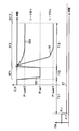
- time t3 when the counter value reaches 30 the repeated generation of the cloud origin on request is stopped and the repeated generation of the cloud origin off request is started. This operation continues at least until time t4 when the counter value reaches 44 as long as the execution subject is in the state SB2.
- a cloud-off request is included in the data block Za and transmitted to the air conditioning panel control device 125.
- the air conditioning panel control device 125 temporarily turns off the compressor drive request CMP as shown in FIG. 6 in the output arbitration process 125b, so that the compressor 2 continues to be temporarily stopped by the A / C_ECU 11.
- a cloud-on request is included in the data block Za and transmitted to the air conditioning panel control device 125.
- the air conditioning panel control device 125 temporarily turns on the compressor drive request CMP as shown in FIG. 6 in the output arbitration process 125b, so that the compressor 2 is continuously driven by the A / C_ECU 11.
- state SB2 when ⁇ Tefin is 6 degrees C or less and the value of counter K exceeds 44, the state transitions to state SC2 in state SC.
- the cloud-on request may or may not be generated for inclusion in the next data block Za.
- ⁇ Tefin exceeds 6 degrees C before the value of the counter K reaches 44 in the state SB2, the state transitions to the state SC1.
- ⁇ Tefin is the difference between the maximum value and the minimum value of Tefin after the last transition to the second determination-stopped state SB2.
- a cloud-on request may be generated for inclusion in the next data block Za.
- a cloud origin on request is generated to be included in the next data block Za Also good.
- the air conditioning panel control device 125 turns on the compressor drive request CMP as shown in FIG. 6 in the output arbitration process 125b, so that the compressor 2 is driven by the A / C_ECU 11.
- the compressor 2 since the transition from the state SB2 to the state SC1 occurs between the time point t1 and the time point t2 of the state SB2 and between the time point t3 and the time point t4, the compressor 2 thereafter starts to operate as intended by the user. Further, even if a transition from the state SB2 to the state SC1 occurs between the time point t2 and the time point t3 in the state SB2, the compressor 2 continues to operate as intended by the user.
- the state transitions to the state SA (more specifically, the state SA2).
- operation G3 is performed. That is, the counters J and K are cleared to zero, and the refrigerant shortage determination value is set to “not determined”.
- a cloud-on request may be generated for inclusion in the next data block Za.
- a cloud-issued on-request may be generated to be included in the next data block Za at a timing after a predetermined time has elapsed (for example, 60 seconds after the start of the state SB1). Good.
- the air conditioning panel control device 125 turns on the compressor drive request CMP as shown in FIG. 6 in the output arbitration process 125b, so that the compressor 2 is driven by the A / C_ECU 11.
- the compressor 2 since the transition from the state SB2 to the state SA occurs between the time point t1 and the time point t2 of the state SB2 and between the time point t3 and the time point t4, the compressor 2 thereafter starts to operate as intended by the user. Further, even if a transition from the state SB to the state SA occurs during the state SB1 or during the state SB2 from the time point t2 to the time point t3, the compressor 2 continues to operate as intended by the user.
- the state SB when the condition S2 is satisfied, that is, (4) The manually received request MOFF is included in the newly received data block Ya. (5) The condition (2) is not satisfied. (6) The condition (3) is not satisfied.
- the state transits to the state SA (more specifically, the state SA2). During this transition, operation G3 is performed. That is, the counters J and K are cleared to zero, and the refrigerant shortage determination value is set to “not determined”.
- the refrigerant shortage determination value is set to “no refrigerant shortage” in a cycle of 1 second.
- the value of the refrigerant shortage determination is set to “the refrigerant shortage exists” in a cycle of 1 second.
- condition S3 when the condition S3 is satisfied in the state SC2, the state transits to the state SA2.
- the case where the condition S3 is satisfied is a case where the data OFF value is “pressed”, or the newly received data block Ya includes a manual-on request MON.
- operation G3 is performed. That is, the counters J and K are cleared to zero, and the refrigerant shortage determination value is set to “not determined”. The above is the contents of the process defined by the refrigerant inspection program 21b.
- Real-time property means that the time lag L is shorter than the reference time.
- the time lag L is the sum of the first processing time, the first communication time, the second processing time, the second communication time, and the third processing time.
- the first processing time is a time from when a state quantity (for example, IG, SPD) indicating an operation state in the in-vehicle system 100 is detected by the in-vehicle system 100 to transmission.
- the second processing time is the time from when the state quantity is transmitted from the in-vehicle system 100 until it is received by the execution subject of the refrigerant inspection program 21b.
- the execution result data (eg, refrigerant shortage determination, cloud-on-on request) is used by using the state quantity in the execution of the refrigerant inspection program 21b.
- This is the time from generation to transmission.
- the second communication time is a time from when the execution subject transmits data of the use result to when the in-vehicle system 100 receives the data.
- the third processing time is the time from when the in-vehicle system 100 receives the use result data until the data is reflected in the control.
- the cloud 200 cloud 400 remotely controls the actuator (that is, the compressor 2) for the diagnosis of the vehicle air conditioner (that is, the refrigerant amount determination), such a diagnosis is executed when there is no real-time property. It is difficult to do.
- coolant inspection program 21b needs to describe the complicated control for controlling the compressor 2, a data size tends to become large. Therefore, by executing the refrigerant inspection program 21b on the cloud 200 side rather than on the vehicle side (A / C_ECU 11 or the air conditioning panel control device 125), the processing load on the vehicle side can be reduced and the memory capacity can be saved. Great effect.
- whether or not there is real-time property is determined based on whether or not the total time is shorter than a predetermined time.
- the state quantities indicating the operating state in the in-vehicle system 100 are specifically IG, SPD, THW, TEfin, PRE, OFF, MON, and MOFF.
- the control in the in-vehicle system 100 is specifically control of the compressor 2, the A / C display 123, and the refrigerant shortage display 124.
- the processing of the refrigerant inspection program 21b is basically executed by being distributed to a plurality of workers 221p, 221q, so that there is not much delay in the processing itself. Therefore, if the delay due to the transmission of the data block Y from the in-vehicle system 100 to the cloud 200 and the transmission of the data block Z from the cloud 200 to the in-vehicle system 100 are both small (for example, less than 0.5 seconds each), the real-time property is OK (good).
- the operation as described above is defined based on the determination result of the real-time property. That is, if the real time property is NG in the state SA where the refrigerant shortage determination is not performed, the refrigerant shortage determination is not started by staying in the state SA and not transitioning to the state SB. Then, only when the real time property changes from NG to OK in the state SA, the state transitions to the state SB and the determination of the lack of refrigerant is started.
- the refrigerant shortage determination is stopped and the state SA is returned to. Further, even after the determination of the lack of refrigerant is stopped and the state returns to the state SA, if the real time property returns from NG to OK, the state transitions to the state SB1, and the determination of the lack of refrigerant is performed again from the beginning. The canceled refrigerant shortage determination may be resumed from the middle.
- the execution subject (workers 221p, 221q) of the count program 21c receives the calculation request (communication 321) for the first time after the job scheduler 221 transmits the control preparation completion notification (communication 307). Start execution and then continue execution.
- the execution subject first clears the cloud-side count value to an initial value (eg, zero) and clears the real-time value to an initial value (eg, OK).
- the process waits for one second from the previous count up of the cloud side count value (start of execution of the count program 21c in S220 for the first time), and when it elapses, the cloud side count value is incremented by one.
- This one second may be measured based on, for example, a clock built in a worker who executes the count program 21c, or based on time information transmitted from an external time server that provides time information. May be.
- the counted up value is immediately transmitted to the job scheduler 221 as a calculation result, and is transmitted from the job scheduler 221 to another worker.
- the cloud-side count value included in the calculation result Zap or Zaq transmitted from the worker 221p or 221q increases by one every second.
- the cloud-side count value in the data block Za transmitted from the job scheduler 221 to the in-vehicle system 100 of the vehicle A via the master server 21 is also incremented by 1 every second.
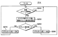
- the execution subject (workers 221p, 221q) of the real-time determination program 21d receives the calculation request (communication 321) for the first time after the job scheduler 221 transmits the control preparation completion notification (communication 307).
- the execution of the determination program 21d is started and then continuously executed.
- the execution subject first determines whether or not a vehicle-side count value is newly received in S240, and repeats this determination until it is determined that it is newly received.
- the data block Ya transmitted in the communication 337 in FIG. 9 includes the vehicle-side count value as described above.
- the received vehicle-side count value is the same value as the cloud-side count value transmitted last time as the calculation result Zap or Zaq from the execution subject of the count program 21c.
- the process proceeds to S250, and the difference between the received vehicle-side count value and the current cloud-side count value (cloud-side count value ⁇ vehicle-side count value) is calculated. Since the transmission cycle T1 on the in-vehicle system 100 side and the transmission cycle T1 on the cloud 200 side are both 1 second, this difference is 2 if there is no significant delay in bidirectional communication between the in-vehicle system 100 of the vehicle A and the cloud 200. Should be: If this difference is 3 or more, it means that either one or both of the transmission from the in-vehicle system 100 of the vehicle A to the cloud 200 and the communication from the cloud 200 to the in-vehicle system 100 have a large delay.
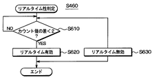
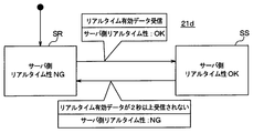
- S260 it is determined whether or not the difference between the count values calculated in the immediately preceding S250 exceeds 2. If not, the real time value is set to “OK” in S270, and the process returns to S240. If exceeded, the real-time value is set to “NG” in S280, and the process returns to S240.
- the real-time value set in S270 and S280 is immediately transmitted to the job scheduler 221 as a calculation result, and is transmitted from the job scheduler 221 to another worker. Therefore, the real time value is used in the processing of the real time determination program 21d without delay.
- the worker managed by the job scheduler 221 counts up the cloud-side count value every second. Then, the cloud side count value is included in the data block Z and transmitted from the worker to the air conditioning panel control device 125 via the job scheduler 221 and the master server 21. Then, the air conditioning panel control device 125 transmits the vehicle side count value having the same value as the received cloud side count value in the data block Y, and the vehicle side count value is transmitted via the master server 21 and the job scheduler 221 to the worker. To reach.
- the worker is based on the time from when the own device transmits the cloud-side count value until the response to the cloud-side count value is received from the air conditioning panel control device 125 (that is, the time required for communication between the two).
- the real-time property is determined. That is, the cloud side count value is time data for confirmation of real-time property, and the vehicle side count value is a response to the time data.
- the real-time property has a long time required for the communication between both of them exceeding a predetermined range, that is, beyond the range where the difference between the received car-side count value and the current cloud-side count value is 2 or less. It is determined by whether or not.
- the A / C_ECU 11 When the ignition of the vehicle A is turned off from on, the A / C_ECU 11 updates the ignition state IG data from on to off. Thereafter, at the transmission timing of the first data block W to be visited, the A / C_ECU 11 transmits the data block W including the ignition state IG to the air conditioning panel control device 125 as already described (communication 381).
- the air conditioning panel control device 125 transmits the data IG included in the data block W to the data block Ya for transmission at the transmission timing of the data block Y that is first visited after receiving the data block W. include.
- the air conditioning panel control device 125 transmits the data block Y to the master server 21 via the wireless converter 13 and the modem 14 (communication 383). At this time, the wireless converter 13 adds its own address to the data block Ya.
- the master server 21 that has received the data block Ya transmits a worker disappearance request to the job scheduler 221 based on the value of the data IG included in the received data block Ya being off (communication 385).
- the job scheduler 221 that has received this worker extinction request communicates with the workers 221p and 221q to end the processes of the refrigerant inspection program 21b, the count program 21c, and the real-time property determination program 21d (communication 387). Thereafter, the job scheduler 221 transmits a notice of completion of worker disappearance to the master server 21 (communication 389).
- the master server 21 that has received the notice of the end of worker disappearance transmits a notice of control acceptance NG to the vehicle A.
- the air conditioning panel control device 125 receives the notification of the control acceptance NG, and then the air conditioning panel control device 125 stops operating.
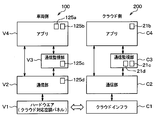
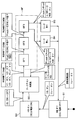
- the functions on the in-vehicle system 100 side include the cloud-compatible air conditioning panel 12 as the hardware layer V1, and the communication unit V2 (wireless converter 13 and modem 14) as the upper layer of the hardware layer V1.
- a communication monitoring unit V3 is provided as a higher hierarchy of the communication unit V2, and the communication monitoring unit V3 includes the function of the count return process 125c of FIG.
- an application layer V4 is provided as an upper layer of the communication unit V2 and the communication monitoring unit V3, and this application layer V4 includes functions of a manual state transition process 125a and an output arbitration process 125b.
- the functions on the cloud 200 side include a master server 21 and a slave server group 22 as the cloud infrastructure layer C1, and a communication unit C2 as an upper layer of the cloud infrastructure layer C1.
- the communication monitoring unit C3 includes a communication monitoring unit C3 as an upper layer of the communication unit C2, and the communication monitoring unit C3 includes functions of a count program 21c and a real time determination program 21d.
- it has the application layer C4 as a hierarchy of the communication part C2 and the communication monitoring part C3, and this application layer V4 contains the function of the refrigerant
- the function of the count return process 125c of the communication monitoring unit V3 is made independent from the functions of the manual state transition process 125a and the output arbitration process 125b of the application layer V4 (that is, realized as different software modules).
- the development of the state transition process 125a and the output arbitration process 125b becomes a good prospect.
- the refrigerant inspection program 21b development will be good. That is, since the difference between the refrigerant inspection program used for stand-alone in the vehicle without using the cloud 200 and the refrigerant inspection program 21b is reduced, it is easy to divert the refrigerant inspection program used for stand-alone in the development of the refrigerant inspection program 21b.
- the cloud 200 determines whether or not the time required for communication between the air conditioning panel control device 125 and one or more servers exceeds a predetermined reference in the state SB. Based on the determination that the predetermined standard is exceeded, the transition from the state SB to the state SA is performed, thereby stopping the determination of the refrigerant shortage of the vehicle air conditioner.
- the workers 221p and 221q function as an example of a refrigerant inspection unit or device by executing the refrigerant inspection program 21b, and execute the real-time determination program 21d to determine the determination unit or device. It serves as an example.
- these programs include instructions for causing a computer (including a server) to function as an inspection unit and a determination unit, and are also provided as program products recorded on a computer-readable non-transition storage medium. Is also possible.
- the communication system of the present embodiment includes an in-vehicle system 30 mounted on a vehicle and a cloud 400 (one or more servers installed in a remote place outside the vehicle and communicating with the in-vehicle system 30. Corresponding to an example).
- the in-vehicle system 30 is a system for detecting evaporative fuel leakage, and includes a fuel tank 31, a communication pipe 32, a canister 33, a purge pipe 34, a first valve 35, an intake passage 36, a throttle valve 37, pipes 38a and 38b. , 38c, 38d. Further, the in-vehicle system 30 includes a second valve 39, a third valve 40, a reference orifice 41, a decompression pump 42, a pressure sensor 43, an evaporator electronic control unit (EV_ECU) 44, a battery 45, an IG switch 46, a relay 47, and wireless conversion. Instrument 48 is included. Each of the first valve 35, the second valve 39, the third valve 40, and the decompression pump 42 corresponds to an example of an actuator.
- the fuel tank 31 stores fuel to be supplied to the engine of the vehicle on which the in-vehicle system 30 is mounted. This fuel is mainly injected from the fuel injection valve and enters the engine.
- the communication pipe 32 is a pipe that communicates with the fuel tank 31 and the canister 33.
- the canister 33 collects the evaporated fuel generated in the fuel tank 31 and entering the canister 33 through the communication pipe 32.
- the purge pipe 34 is a pipe having one end communicating with the canister 33 and the other end communicating with the intake passage 36.
- the first valve 35 is disposed in the middle of the purge pipe 34.
- the first valve 35 is a valve that adjusts the amount of evaporated fuel purged from the canister 33 to the intake passage 36 through the purge pipe 34 during engine operation or the like.
- the intake passage 36 is a passage for sending air to the engine.
- a throttle valve 37 is disposed inside the intake passage 36.
- the throttle valve 37 is a valve that adjusts the amount of air flowing into the engine from the intake passage 36 by changing the throttle opening.
- the canister connection pipe 38a is a pipe having one end communicating with the canister 33 and the other end communicating with the first atmospheric pipe 38b, the second atmospheric pipe 38c, and the bypass pipe 38d.
- the first atmosphere pipe 38b is a pipe having one end communicating with the canister connection pipe 38a, the second atmosphere pipe 38c, and the bypass pipe 38d, and the other end communicating with a space outside the vehicle.
- the second atmosphere pipe 38c is a pipe having one end communicating with the canister connection pipe 38a, the first atmosphere pipe 38b, and the bypass pipe 38d, and the other end communicating with a space outside the vehicle.
- One end of the bypass pipe 38d communicates with the one end of the canister connection pipe 38a, the first atmospheric pipe 38b, and the atmospheric pipe 38c. Further, the other end of the bypass pipe 38d communicates with the second atmospheric pipe 38c.
- a second valve 39 is disposed in the middle of the first atmospheric tube 38b.
- the second valve 39 is a valve that opens and closes a passage inside the first atmospheric tube 38b.
- a third valve 40 is disposed in the middle of the bypass pipe 38d.
- the third valve 40 is a valve that opens and closes a passage inside the bypass pipe 38d.
- a reference orifice 41 is disposed in the middle of the second atmospheric tube 38c.
- the inner diameter of the passage of the reference orifice 41 is a reference diameter (for example, 0.5 mm) that is an upper limit value of the allowable amount of leakage of gas including evaporated fuel from the fuel tank 31.
- the decompression pump 42 is disposed on the downstream side of the reference orifice 41 of the second atmospheric pipe 38c (that is, the other end side of the second atmospheric pipe 38c), and is upstream of the decompression pump 42 in the second atmospheric pipe 38c (that is, on the other side). Gas is sucked from the one end side of the second atmospheric pipe 38c and discharged downstream.
- the pressure sensor 42 detects the pressure at the detection position downstream of the reference orifice 41 in the second atmospheric pipe 38c and upstream of the pressure reducing pump 42.
- the other end of the bypass pipe 38d communicates downstream of the detection position in the second atmospheric pipe 38c and upstream of the decompression pump 42.
- the battery 45 is a secondary battery mounted on the vehicle and supplies power to various devices of the vehicle.
- the IG switch 46 is a switch for switching between supplying and not supplying electric power from the battery 45 to the various devices including the EV_ECU 44 via the IG line.
- the relay 47 is a switch circuit that turns on / off the power supply from the battery 45 to the EV_ECU 44 regardless of whether the IG switch 46 is on or off.
- the EV_ECU 44 controls the first valve 35, the second valve 39, the third valve 40, the decompression pump 42, and the like according to a command from the cloud 400, as will be described later.
- the EV_ECU 44 can be realized by, for example, a known microcomputer having a CPU, a memory such as a ROM and a RAM, and an input / output unit.
- the EV_ECU 44 controls the first valve 35, the second valve 39, the third valve 40, the decompression pump 42, and the like in order to diagnose the evaporation system, and more specifically, to determine whether there is a leak of evaporated fuel in the evaporation system. .
- the evaporation system is an apparatus having the entire fuel tank 31, the entire communication pipe 32, the entire canister 33, and the canister 33 side end of the purge pipe 34 to the first valve 35, and corresponds to an example of an in-vehicle apparatus.
- the state of this evaporation system changes depending on the operation contents of the first valve 35, the second valve 39, the third valve 40, and the decompression pump 42.
- the EV_ECU 44 transmits the data block T to the wireless converter 48 every second.
- the contents of the data block T will be described later.
- the wireless converter 48 is a device that relays between the EV_ECU 44 and the modem 14. Specifically, the wireless converter 48 includes the address (for example, MAC address) of the wireless converter 48 in the data block T transmitted from the EV_ECU 44 and transmits the data block T to the modem 14.
- the address for example, MAC address
- the modem 14 is a device such as a mobile phone, and is a device that can be carried by a vehicle occupant and brought into the vehicle interior to communicate with the wireless converter 48 and the cloud 400 that is a group of servers installed outside the vehicle. As shown in FIG. 20, the modem 14 transmits the data block T received from the wireless converter 48 to the cloud 400 every second.
- the modem 14 and the cloud 400 communicate via a wide area network such as the Internet.
- the data block T includes pressure sensor data P, an ignition state IG, a vehicle side count value, real-time valid data, and a MAC address (address of the wireless converter 48).
- the EV_ECU 44 transmits the data block T to the wireless converter 48.
- the pressure sensor data P, the ignition state IG, the vehicle side count value, and the real-time effective data constitute inspection data necessary for diagnosing the evaporation system and determining the leakage of the evaporated fuel.
- the real-time valid data is event data transmitted only when the EV_ECU 44 determines that there is real-time property.
- the data other than the data clearly indicating the event data is so-called level data.
- Level data is transmitted every cycle, whereas event data is transmitted only when a specific condition is satisfied.
- the modem 14 repeatedly receives the data block S from the cloud 400 as shown in FIG. As shown in FIG. 21, the data block S has an evaluation determination, pump on request, pump off request, relay on request, relay off request, V1 on request, V1 off request, V2 on request, V2 off request, V3 on request, V3 off request, 11 pieces of data called cloud side count value are included.
- the evaporative determination is event data indicating a determination result of the presence or absence of a leak of evaporated fuel in the evaporation system.
- the pump-on request is event data indicating that the operation start of the decompression pump 42 is requested from the cloud 400 side for the diagnosis of the evaporation system.
- the pump-off request is event data indicating that the operation of the decompression pump 42 has been requested from the cloud 400 side for the diagnosis of the evaporation system.
- the relay ON request is event data indicating that the ON operation of the relay 47 is requested from the cloud 400 side for the evaporative diagnosis.
- the relay-off request is event data indicating that the cloud 47 has requested that the relay 47 be turned off when the evaporative diagnosis ends.
- the V1 ON request is event data indicating that the opening operation of the first valve 35 is requested from the cloud 400 side.
- the V1 off request is event data indicating that the closing operation of the first valve 35 is requested from the cloud 400 side for the diagnosis of the evaporation system.
- the V2 ON request is event data indicating that the opening operation of the second valve 39 is requested from the cloud 400 side for the evaporative diagnosis.
- the V2 off request is event data indicating that the closing operation of the second valve 39 is requested from the cloud 400 side for the diagnosis of the evaporation system.
- the V3 ON request is event data indicating that the opening operation of the third valve 40 is requested from the cloud 400 side for evaporative diagnosis.
- the V3 off request is event data indicating that the closing operation of the third valve 40 is requested from the cloud 400 side for the diagnosis of the evaporation system.
- the cloud side count value will be described later.
- the cloud 400 transmits the data block S including the cloud-side count value to the modem 14 repeatedly and periodically, specifically with a period of 1 second. Further, among the data that may be included in the data block S, each of the event data is included in the data block S only when a specific condition is satisfied.
- the modem 14 transmits the received data block S to the radio converter 48, and the radio converter 48 transmits the received data block S to the EV_ECU 44.
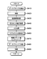
- the EV_ECU 44 is configured to execute the process shown in FIG. First, in S410, the data block S last received from the cloud 400 via the modem 14 and the wireless converter 48 is read into the RAM.
- any of the pump-on request, the pump-off request, the relay-on request, the relay-off request, the V1-on request, the V1-off request, the V2-on request, the V2-off request, the V3-on request, and the V3-off request is added to the data block S read in S410 immediately before. If one or more of them are included, the first valve 35, the second valve 39, the third valve 40, the pressure reducing pump 42, and the relay 47 are controlled as necessary to realize the included request. . If none of the requests is included in the data block S, the process proceeds to S430 without performing control.
- the data block S read out in the immediately preceding S410 includes data for determining the evaluation
- the data is recorded in a storage medium (for example, the flash memory of the EV_ECU 44).
- the data for the determination of the evaporative determination recorded in this way is later read out and used for vehicle analysis, failure determination and the like. If the data block S contains the data for the evaluation of the evaluation, the process proceeds to S440 without doing anything.
- the sensor value is acquired. Specifically, the pressure sensor value P is acquired based on the detection result of the pressure sensor 43.
- the pressure sensor value P is a pressure downstream of the reference orifice 41 and upstream of the decompression pump 42 in the second atmospheric tube 38c.
- the ignition state IG of the vehicle is acquired. If the IG switch 46 is on, the ignition state IG is on. If the IG switch 46 is off, the ignition state IG is off.
- the presence / absence of real time is determined. Details of this determination will be described later.
- the value of the vehicle side count value (vehicle side real-time property confirmation count value) in the RAM is incremented by one. As a result, the cloud-side count value increases by 1 per second.
- a data block T is created and transmitted. Specifically, a data block T including the pressure sensor value P acquired in the immediately preceding S440, the ignition state IG acquired in the immediately preceding S450, and the vehicle side count value updated in the immediately preceding S470 is created. If the determination result of S460 immediately before is “with real-time”, real-time valid data is included in the data block T. However, if the determination result of S460 immediately before is “no real-time property”, real-time valid data is not included in the data block T.
- the data block T created in this way is further transmitted to the wireless converter 48.
- the radio converter 48 adds an address to the data block T and transmits it to the modem 14, and the modem 14 transmits the data block T to which the address is added to the cloud 400.
- step S490 the EV_ECU 44 waits for a predetermined time, specifically, 1 second, and then returns to step S410.
- the EV_ECU 44 thus executes the loop of S410 to 490 at a cycle of 1 second.
- the EV_ECU 44 performs control and records a diagnosis result based on the latest data block S received at that time in a cycle of 1 second.
- the EV_ECU 44 transmits the data block T including the latest pressure sensor value, ignition state IG, and vehicle-side count value at that time to the cloud 400 via the wireless converter 48 and the modem 14 in a cycle of 1 second. . Accordingly, the vehicle-side count value increases by 1 each time the data block T is transmitted.
- the EV_ECU 44 includes the real-time valid data in the data block T if the communication between the EV_ECU 44 and the cloud 400 has real-time characteristics.
- the cloud 400 includes a master server 21 having the same hardware configuration as that of the first embodiment and a slave server group 22 having the same hardware configuration as that of the first embodiment.
- the in-vehicle system 30 and the modem 14 shown in FIG. 1 are mounted on each of the plurality of vehicles D, E, and F, and the EV_ECU 44 of each of the in-vehicle systems 30 is mounted on the same vehicle. 14 to communicate with the master server 21.
- the master server 21 is configured to execute a calculation instruction process 21a and has a storage medium (not shown).
- the storage medium includes a diagnostic program 21e, a count program 21f, and a real-time determination program. 21 g is recorded.
- the software recorded in the storage medium of the master server 21 in this embodiment is different from that in the first embodiment.
- the procedure in which the master server 21 assigns one job scheduler to each of the vehicles D, E, and F and sends the programs 21e, 21f, and 21g may be the same as that in the first embodiment, or other known The distributed processing technique may be used. Further, the procedure in which each job scheduler 221, 222, 223 distributes the processing of the programs 21e, 21f, 21g to a plurality of workers 221p, 221q, 222p, 222q, 223p, 223q managed by the own machine is also performed in the first embodiment. It may be the same as the form, or may be realized by using other known distributed processing techniques.
- the processing of the programs 21e, 21f, and 21g to be performed on the vehicle D is appropriately distributed and assigned to the plurality of workers 221p and 221q by the job scheduler 221, thereby reducing the processing load on each worker.
- FIG. 24 shows a data flow from the vehicle D to the workers 221p and 221q as described above.
- the data blocks T transmitted from the vehicles D, E, and F are denoted as Td, Te, and Tf, respectively.
- the master server 21 that has received the data block Td from the modem 14 of the vehicle D transmits a job request communication RTd including the data block Td to the job scheduler 221.
- the job scheduler 221 that has received the job request communication RTd defines the programs 21e, 21f, and 21g based on the contents of the data block Td included in the job request communication RTd and the processing contents of the programs 21e, 21f, and 21g.
- the processing is distributed to a plurality of workers 221p and 221q managed by the own device. Therefore, the job scheduler 221 transmits necessary calculation requests Tdp and Tdq to each of the plurality of workers 221p and 221q managed by the own machine.
- the calculation requests Tdp and Tdq include the contents of processing to be performed by each of the workers 221p and 221q and data necessary for the processing (the contents of the latest data block Ta and the like).
- the workers 221p and 221q operate according to the calculation requests Tdp and Tdq from the job scheduler 221, respectively. As shown in FIG. 25, the calculation results Sdp and Sdq obtained as a result of the operation are used as the job scheduler 221. Send to. Evapolique determination, pump-on request, pump-off request, relay-on request, relay-off request, V1-on request, V1-off request, V2-on request, V2-off request, V3-on request, V3-off request, cloud-side count values are calculated results Sdp, Sdq Is included in either. In addition, various variables used in the calculation are included in the calculation results Sdp and Sdq.
- the job scheduler 221 that has received the calculation results Sdp and Sdq immediately transmits the calculation results to each of the plurality of workers 221p and 221q managed by the own machine (that is, with a delay sufficiently shorter than 1 second). In this way, the values of various data are consistent among the plurality of workers 221p and 221q managed by the same job scheduler 221.
- the job scheduler 221 determines (if any) an evaluation of the occurrence of a police, (if any) a pump-on request, (if any) a pump-off request, (if any) a relay-on request, and (if any) a relay-off from the latest received calculation results Sdp and Sdq.
- Request (if any) V1 on request, (if any) V1 off request, (if any) V2 on request, (if any) V2 off request, (if any) V3 on request, (if any) V3 off request.
- the cloud-side count value is extracted to generate a data block Sd, and job result communication including the data block Sd is repeatedly and periodically transmitted to the master server 21 (specifically, in a cycle of 1 second).
- the data blocks S to be transmitted to the vehicles D, E, and F are denoted as Sd, Se, and Sf, respectively.
- the master server 21 that has received this job result communication immediately transmits the data block Sd included in the job result communication to the vehicle D. Therefore, the transmission of the data block Sd from the master server 21 to the vehicle D is also repeatedly and periodically performed (specifically, at a cycle of 1 second).
- the EV_ECU 44 receives this data block Sd via the modem 14 and the wireless converter 48. Then, the EV_ECU 44 reads the data block Sd into the RAM in S410 of the loop of FIG. 22 immediately after receiving the data block Sd in the processing of FIG. 22, and in S420, based on the data in the read data block Sd, Accordingly, the first valve 35, the second valve 39, the third valve 40, the decompression pump 42, and the relay 47 are controlled. In S430, if the data of the evaluation determination in the data block Sd is included, the data is recorded on the storage medium. In S460 immediately after that, a real-time determination is performed based on the cloud-side count value and the current vehicle-side count value in the data block Sd.
- the vehicle E and the cloud 400 communicate with the master server 21, the job scheduler 222, the worker 222p, and the worker 222q by the same operation as the vehicle D and the cloud 400.
- vehicle E data block Te, job request communication RTe, calculation request Tep, calculation request Teq, calculation result Sep, calculation result Seq, data block Se, job scheduler 222, worker 222p, and worker 222q, respectively. This replacement is also effective for the following description.
- the vehicle F and the cloud 400 also communicate with the master server 21, the job scheduler 223, the worker 223p, and the worker 223q by the same operation as the vehicle D and the cloud 400.
- the diagnostic program 21e is a program for determining whether or not there is a leak of evaporated fuel in the evaporation system of the vehicle. As shown in FIG. 26, in the diagnostic program 21e, six states SD, SE, SF, SG, SH, and SI are defined. The state SF has child states SF1, SF2, and SF3.
- the values of the ignition state IG and the pressure sensor value P used in the diagnostic program 21e are determined by referring to the data block Ya in the latest job request communication RYa received from the master server 21 by the job scheduler 221.
- the execution subject of the diagnostic program 21e (in this case, workers 221p and 221q) is in the + B off state SI.
- the execution subject of the diagnostic program 21e in this case, workers 221p and 221q
- the vehicle D it is assumed that the IG switch 46 and the relay 47 are off and the EV_ECU 44 is stopped.
- the EV_ECU 44 starts transmitting the data block Ta as described above by the processing of FIG. 22, but the value of the ignition state IG in the data block Ta is turned on. It has become.
- the value of the ignition state IG is transmitted as a calculation request via the master server 21 and the job scheduler 221 to the worker who executes the diagnostic program 21e. Then, when the execution subject is in the state SI, it detects that the ignition state IG is on, transmits a relay on request to the job scheduler 221 as a calculation result (Sdp or Sdq), and transitions to the + B on state SD. To do.
- the job scheduler 221 When the job scheduler 221 receives the relay-on request, the job scheduler 221 creates a data block Sd including the relay-on request at the transmission timing of the first data block Sd thereafter, and transmits the data block Sd to the master server 21. Master server 21 transmits data block Sd including this relay-on request to vehicle D.
- the EV_ECU 44 of the vehicle D receives this data block Sd via the modem 14 and the wireless converter 48. Further, the EV_ECU 44 turns on the relay 47 in accordance with this relay on request in S420 of the loop of FIG. Thus, EV_ECU 44 is in a state where it can continue to operate by receiving power supply from battery 45 even when IG switch 46 is turned off.
- the execution subject remains in the state SD.
- the IG switch 46 is on, the engine is operated and the traveling of the vehicle D is realized.
- the EV_ECU 44 continues to operate while receiving power supply via the relay 47. Then, the EV_ECU 44 turns off the ignition state IG in S450 of the loop of FIG. 22 immediately after the IG switch 46 is turned off. The EV_ECU 44 further transmits a block Ta including data of the ignition state IG having an OFF value in S480 immediately after that.
- the value of the ignition state IG is transmitted as a calculation request via the master server 21 and the job scheduler 221 to the worker who executes the diagnostic program 21e. Then, when the execution subject is in the state SD, the execution subject detects that the ignition state IG has been turned off from on, and transitions to the leak test non-execution state SD.
- the leak test unexecuted state SD is a state immediately before starting the leak test. Thus, after the engine stops in the vehicle D and the ignition state IG is turned off, the leak test is performed. Even after the transition from the state SD to the state SE, the relay 47 remains on in the EV_ECU 44.
- the opening degree of the first valve 35 is determined by a factor resulting from engine control. Further, in a situation where the leak test is not performed, the second valve 39 and the third valve 40 are in a fully open state, a fully closed state, and a fully closed state, respectively. In a situation where the leak test is not performed, the decompression pump 42 is inactive.
- the execution subject of the diagnostic program 21e waits until the elapsed time from the transition to the state SE reaches a predetermined time T11.
- a V1 off request, a V2 on request, a V3 off request, and a pump on request are transmitted to the job scheduler 221 as calculation results, and a transition is made to the child state SF1 of the leak test execution state SF.
- the state SF is a state in which diagnosis is being performed
- the child state SF1 corresponds to the state of the first stage of diagnosis
- the child state SF2 corresponds to the state of the second stage of diagnosis
- the child state SF3 corresponds to the state of the third stage of diagnosis. .
- the job scheduler 221 When the job scheduler 221 receives the V1 off request, V2 on request, V3 off request, and pump on request, the V1 off request, V2 on request, V3 off request, and pump on request are transmitted at the transmission timing of the first data block Sd thereafter. Is created and transmitted to the master server 21. The master server 21 transmits this data block Sd to the vehicle D.
- EV_ECU 44 of vehicle D receives this data block Sd via modem 14 and wireless converter 48. Further, the EV_ECU 44 immediately closes the first valve 35 according to the V1 off request, the V2 on request, the V3 off request, and the pump on request in the data block Sd in S420 of the loop of FIG. 39 is fully opened, the third valve 40 is fully opened, and the decompression pump 42 is operated. As a result, atmospheric air is sucked into the decompression pump 42 through the first atmospheric tube 38b and the second atmospheric tube 38c.
- the execution subject of the diagnostic program 21e waits until the elapsed time from the transition to the state SF1 reaches a predetermined time T12.
- the pressure sensor value P decreases and stabilizes in the vicinity of the pressure corresponding to the inner diameter of the passage of the reference orifice 41, as shown by the solid line 52 in FIG.
- the EV_ECU 44 transmits the pressure sensor value P at that point in the data block T every second in the process of FIG.
- the value of the pressure sensor value P is transmitted as a calculation request to the execution subject of the diagnostic program 21e via the master server 21 and the job scheduler 221.
- the execution subject of the diagnostic program 21e records the latest pressure sensor value P received from the vehicle D at that time as a reference pressure Preref in the RAM. Further, the process G5 is executed to make a transition to the state SF2.
- process G5 the execution subject of the diagnostic program 21e transmits a V3 off request and a pump off request to the job scheduler 221 as calculation results.
- the job scheduler 221 When the job scheduler 221 receives the V3 off request and the pump off request, the job scheduler 221 creates a data block Sd including the V3 off request and the pump off request at the transmission timing of the first data block Sd thereafter, and transmits the data block Sd to the master server 21.
- the master server 21 transmits this data block Sd to the vehicle D.
- EV_ECU 44 of vehicle D receives this data block Sd via modem 14 and wireless converter 48. Further, the EV_ECU 44 immediately switches the third valve 40 to the fully closed state in accordance with the V3 off request and the pump off request in the data block Sd in S420 of the loop of FIG. As a result, as indicated by a solid line 52 in FIG. 27, the pressure sensor value P detected by the pressure sensor 43 rises to the value of atmospheric pressure.
- the execution subject of the diagnostic program 21e further transmits a V1 off request, a V2 off request, a V3 on request, and a pump on request to the job scheduler 221 as calculation results.
- the job scheduler 221 receives the V1 off request, the V2 off request, the V3 on request, and the pump on request, the V1 off request, the V2 off request, the V3 on request, and the pump on request are transmitted at the transmission timing of the first data block Sd thereafter. Is created and transmitted to the master server 21. The master server 21 transmits this data block Sd to the vehicle D.
- EV_ECU 44 of vehicle D receives this data block Sd via modem 14 and wireless converter 48. Further, the EV_ECU 44 keeps the first valve 35 fully closed according to the V1 off request, the V2 off request, the V3 on request, and the pump on request in the data block Sd in S420 of the loop of FIG. The valve 39 is switched to fully closed, and the third valve 40 is kept fully open. Thereby, the gas inside the evaporation system is sucked by the decompression pump 42.
- the execution subject of the diagnostic program 21e waits until the elapsed time from the transition to the state SF2 reaches a predetermined time T13. If there is a leak hole in the evaporation system having a diameter larger than the inner diameter of the passage of the reference orifice 41, the pressure sensor value P decreases during standby of the execution subject, but from the reference pressure Pref as shown by the solid line 53 in FIG. Stays high. If there is a leak hole having a diameter smaller than the passage inner diameter of the reference orifice 41 in the evaporation system, or there is no leak hole in the evaporation system, the pressure sensor value P is indicated by a solid line in FIG.
- the pressure drops to a value lower than the reference pressure Pref. Even during this standby, the EV_ECU 44 transmits the pressure sensor value P at that point in the data block T every second in the process of FIG.
- the value of the pressure sensor value P is transmitted from the EV_ECU 44 via the master server 21 and the job scheduler 221 to the execution subject of the diagnostic program 21e as a calculation request.
- the execution subject of the diagnostic program 21e records the latest pressure sensor value P received from the vehicle D at that time as a pressure Pleak in the RAM. Further, the state transits to the state SF3.
- the pressure Pleak2 is recorded in the RAM as the pressure Pleak.
- the pressure Pleak1 is recorded in the RAM as the pressure Pleak.
- the execution subject of the diagnostic program 21e transmits an evaluation result having an ON value to the job scheduler 221 as an operation result when the value of Pleak in the RAM is larger than the value of Pref. Then, the execution subject further transitions to a leaked state SG.
- the execution subject of the diagnostic program 21e transmits an evaluation result having an off value to the job scheduler 221 as a calculation result when the value of Pleak in the RAM is smaller than the value of Pref. Then, the execution subject further transitions to a leak-free state SH.
- the job scheduler 221 When the job scheduler 221 receives the evaluation determination, the job scheduler 221 creates a data block Sd including the evaluation determination at the transmission timing of the first data block Sd thereafter, and transmits the data block Sd to the master server 21.
- the master server 21 transmits this data block Sd to the vehicle D.
- EV_ECU 44 of vehicle D receives this data block Sd via modem 14 and wireless converter 48. Furthermore, the EV_ECU 44 records the evaluation value of the evaluation in the data block Sd in the flash memory in S430 of the loop of FIG. 22 immediately after that. When the solid line 53 of FIG. 27 is realized, the ON value of the evaluation poll is recorded, and when the solid line 54 is realized, the OFF value of the evaluation determination is recorded.
- the execution subject of the diagnostic program 21e determines that a diagnosis result (that is, an evaporative determination) has been recorded in the vehicle D based on the fact that a predetermined period has elapsed since the transition to the leaked state SG.
- the relay off request is transmitted to the job scheduler 221 as a calculation result, and the state transits to the + B off state SI. Thereby, the diagnosis of the evaporation system of the vehicle D is completed.
- the execution subject of the diagnostic program 21e determines that the diagnosis result (that is, the evaporative determination) has been recorded in the vehicle D based on the elapse of a predetermined period after the transition to the no-leakage state SH. Then, a relay-off request is transmitted as a calculation result to the job scheduler 221 and a transition to the + B off state SI is made. Thereby, the diagnosis of the evaporation system of the vehicle D is completed.
- the job scheduler 221 When the job scheduler 221 receives the relay-off request, the job scheduler 221 creates a data block Sd including the relay-off request at the transmission timing of the first data block Sd thereafter, and transmits the data block Sd to the master server 21.
- the master server 21 transmits this data block Sd to the vehicle D.
- EV_ECU 44 of vehicle D receives this data block Sd via modem 14 and wireless converter 48. Further, the EV_ECU 44 turns off the relay 47 in accordance with the relay off request in the data block Sd in S420 of the loop of FIG. 22 immediately after that. As shown in FIG. 27, at this point, the IG switch 46 is already off. Accordingly, at this time, the EV_ECU 44 stops receiving power and stops.
- the execution subject of the diagnostic program 21e makes a transition to the state SE when the server-side real-time value is NG in the state SF (that is, the states SF1, SF2, and SF3). In other words, if the real-time property is impaired during the evaporative diagnosis, the diagnosis is stopped. After the transition to the state SE, if the elapsed time from the transition to the state SE reaches a predetermined time T11, the transition to the state SF1 is performed by the process as described above.
- the data block T is transmitted from the vehicle D to the cloud 400 at a cycle of 1 second as described above even while the execution subject of the diagnostic program 21e executes the diagnostic program 21e and transitions between the states.
- Data blocks are transmitted from the cloud 400 to the vehicle D at a cycle of 1 second.
- the transmitted data may not reach the destination immediately due to factors such as communication delay.
- Real-time property means that the time lag L is shorter than the reference time.
- the time lag L is the sum of the first processing time, the first communication time, the second processing time, the second communication time, and the third processing time.
- the first processing time is a time from when a state quantity (for example, pressure sensor value P, ignition state IG) indicating an operation state in the in-vehicle system 30 is detected by the in-vehicle system 30 to transmission.
- the second processing time is the time from when the state quantity is transmitted from the in-vehicle system 30 until it is received by the execution subject of the diagnostic program 21e.
- the execution result data (for example, an eval police determination, a relay on request, and a V2 on request) is used by using the state quantity in the execution of the diagnostic program 21e. This is the time from generation to transmission.
- the second communication time is a time from when the execution subject transmits data of the use result to when the in-vehicle system 30 receives the data.
- the third processing time is a time from when the in-vehicle system 30 receives the data of the usage result until the data is reflected in the control.
- the cloud 400 remotely controls the actuators 35, 39, 40, and 42 for the evaporative diagnosis, it is difficult to execute such a diagnosis when there is no real-time property.
- the diagnostic program 21e needs to describe complicated control for controlling the actuators 35, 39, 40, and 42, the data size tends to increase. Therefore, by executing such a diagnostic program 21e on the cloud 400 side rather than on the EV_ECU 44 side, the effect of reducing the processing load of the EV_ECU 44 and the effect of saving the memory capacity are greater.
- the state quantity indicating the operating state in the in-vehicle system 30 is the control of the in-vehicle system 30, specifically, the first valve 35, the second valve 39, the third valve 40, and the decompression pump 42. Control, recording to a storage medium, and the like.
- the processing of the diagnostic program 21e is basically executed by being distributed to a plurality of workers 221p and 221q, so that there is not much delay in the processing itself. Therefore, if the delays due to the transmission of the data block T from the in-vehicle system 30 to the cloud 400 and the transmission of the data block S from the cloud 400 to the in-vehicle system 30 are both small (for example, less than 0.5 seconds each), the real-time property is OK (good).
- the operation as described above is defined in the diagnostic program 21e based on the determination result of the real time property. That is, if the real-time property is NG in the state SF in which the evaporation system diagnosis is performed, the evaporation system diagnosis is stopped by returning to the state SE.
- the vehicle-side count value and the cloud-side count value which are quantities for determining such real-time properties, will be described.
- the EV_ECU 44 of the vehicle D increases the value of the vehicle-side count value by 1 in S470 every second in the process of FIG. 22, and in S480, the data block Ta including the vehicle-side count value is included.
- the vehicle-side count value is transmitted as a calculation request to the execution subject of the count program 21f via the master server 21 and the job scheduler 221.
- the execution subject of the count program 21f first waits until receiving the vehicle-side count value in S510, as shown in FIG. 28, and then proceeds to S520 and received in the immediately preceding S510.
- the same value as the car-side count value is set as the cloud-side count value.
- the cloud side count value is transmitted to the job scheduler 221 as a calculation result.
- the job scheduler 221 When the job scheduler 221 receives the cloud-side count value, the job scheduler 221 creates a data block Sd including the cloud-side count value at the transmission timing of the first data block Sd thereafter, and transmits the data block Sd to the master server 21.
- the master server 21 transmits this data block Sd to the vehicle D.
- EV_ECU 44 of vehicle D receives this data block Sd via modem 14 and wireless converter 48. Further, the EV_ECU 44 performs real-time determination using the cloud-side count value in the data block Sd in S460 of the loop of FIG. 22 immediately after that.
- the EV_ECU 44 first determines in S610 that the value obtained by subtracting the cloud-side count value received in the immediately preceding S410 from the current vehicle-side count value is less than 2 (ie, 1 or 0), as shown in FIG. ).
- the process proceeds to 620. If it is determined that the number is 2 or more, the process proceeds to S630. In S620, it determines with real time being effective, and complete
- real-time valid data is not included in the data block T and transmitted in S480. If it is determined in S460 that the real-time is valid, the real-time valid data is included in the data block Ta and transmitted in S480. The real-time valid data is transmitted as an operation request to the execution subject of the real-time determination program 21g via the master server 21 and the job scheduler 221.
- the operation defined by the real time determination program 21g will be described with reference to FIG.
- the execution subject (workers 221p, 221q) of the real-time property determination program 21g receives a calculation request for the real-time property determination program 21g from the job scheduler 221, the execution subject of the real-time property determination program 21g starts, and then continuously. To run.
- State SR is a starting state.
- the execution subject When the execution subject receives the real-time valid data in the state SR, the execution subject sets the server-side real-time property value in the RAM to “OK”, and transitions to the state SS. If the execution subject does not receive the real-time valid data for 2 seconds or longer in the state SS, the execution subject sets the server-side real-time property value in the RAM to “NG” and transitions to the state SR. As described above, the server-side real time value set by executing the real time determination program 21d is used in the diagnostic program 21e.
- the EV_ECU 44 of the vehicle D counts up the vehicle side count value every second. Then, the vehicle side count value is included in the data block T and transmitted from the EV_ECU 44 to the worker via the master server 21 and the job scheduler 221. The worker transmits the cloud-side count value having the same value as the received vehicle-side count value in the data block S, and the cloud-side count value reaches the EV_ECU 44 via the job scheduler 221 and the master server 21. Therefore, the EV_ECU 44 determines the real-time based on the time from when the own device transmits the vehicle-side count value until the response to the vehicle-side count value is received from the cloud 400 (that is, the time required for communication between the two). The sex is being judged. That is, the vehicle-side count value is time data for confirmation of real-time property, and the cloud-side count value is a response to the time data.
- the time required for communication between the two exceeds a predetermined range, that is, whether or not the difference between the received cloud-side count value and the current vehicle-side count value is less than 2. It is judged by.
- the EV_ECU 44 determines whether or not the time required for communication between the EV_ECU 44 and one or more servers exceeds a predetermined standard. Only when it does not exceed, real-time valid data is transmitted to the cloud 400. Then, the cloud 400 determines whether or not there is real-time property based on whether or not real-time valid data has been received within the past 2 seconds. When there is no real-time property, the cloud 400 stops the evaporative diagnosis, more specifically, the determination of whether or not there is a leak of evaporated fuel, by transitioning from the state SF to the state SE.
- the real-time determination is realized in such a manner that the diagnosis of the evaporation system is stopped when the delay in communication between the EV_ECU 44 and the cloud 400 exceeds a predetermined standard. Thereby, it is possible to reduce the waste of continuing the diagnosis of the evaporative system until there is a high possibility that the proper evaporative system cannot be diagnosed due to poor real-time characteristics.
- the workers 221p and 221q function as an example of an inspection unit or a device by executing the diagnostic program 21e, and function as an example of a determination unit or a device by executing the real-time determination program 21g.
- these programs include instructions for causing a computer (including a server) to function as an inspection unit and a determination unit, and are also provided as program products recorded on a computer-readable non-transition storage medium. Is also possible.
- the vehicle-side count value transmitted by the air conditioning panel control device 125 is the same as the cloud-side count value received immediately before.
- the vehicle-side count value may be a value that can be understood to be a value corresponding to the cloud-side count value received immediately before.
- the vehicle-side count value may be a value after a predetermined calculation is performed on the cloud-side count value received immediately before.
- the workers 221p and 221q of the cloud 200 determine whether or not the difference between the time when the vehicle-side count value is received and the time when the cloud-side count value is received exceeds 2 seconds in S260 of the real-time property determination program 21d. By determining, real-time property can be determined.
- the cloud 200 does not necessarily need to transmit the cloud-side count value, and the air conditioning panel control device 125 unilaterally transmits the vehicle-side count value including the transmission time to the cloud 200, and the workers 221p and 221q of the cloud 200 are
- the real-time property can be determined by determining whether or not the value obtained by subtracting the transmission time included in the vehicle-side count value from the time when the vehicle-side count value is received exceeds 2 seconds.
- the cloud 200 may be configured to transmit current time information instead of the cloud-side count value. In that case, both the subsequent cloud 200 and the in-vehicle system 100 can obtain the same effect as the above-described embodiment if the current time information is used similarly to the cloud-side count value.
- the execution subject of the count program 21c in the cloud 200 may measure the current time information by a process other than the count program 21c in the own device, but obtains it from another device (for example, a time server on the network). May be.
- the cloud 200 executes the count program 21c and the real-time determination program 21d, and the air conditioning panel control device 125 executes the count return process 125c. It is like that. That is, the count value (cloud side count value) is transmitted from the cloud 200 to the air conditioning panel control device 125, and the same count value (vehicle side count value) is returned from the air conditioning panel control device 125 to the cloud 200. Based on the difference between the count values, the cloud 200 determines the real time property.
- the determination of real-time property may be performed by the air conditioning panel control device 125. That is, the count value is transmitted from the air conditioning panel control device 125 to the cloud 200, and the same count value is returned from the cloud 200 to the air conditioning panel control device 125, and the air conditioning panel control device 125 is based on the difference between the two count values. May determine real-time characteristics.
- the cloud 200 may execute the count return process 125c, and the air conditioning panel control device 125 may execute the processes of the count program 21c and the real-time determination program 21d. However, at that time, the data transmission destination and the like are appropriately corrected during each process. In addition, information necessary for these processes can be exchanged by communication between the cloud 200 and the air conditioning panel control device 125.
- the A / C_ECU 11 may realize the function of the air conditioning panel control device 125 instead of the air conditioning panel control device 125.
- the air conditioning panel control device 125 may be configured to realize the function of the A / C_ECU 11 instead of the A / C_ECU 11.
- the cloud 200 is realized by a plurality of servers 21, 221, 222, 223, 221p, 221q, 222p, 222q, 223p, and 223q, but may be realized by a single server. That is, the cloud 200 may be realized by any number of servers.
Landscapes
- Engineering & Computer Science (AREA)
- Mechanical Engineering (AREA)
- General Engineering & Computer Science (AREA)
- Chemical & Material Sciences (AREA)
- Combustion & Propulsion (AREA)
- Physics & Mathematics (AREA)
- Thermal Sciences (AREA)
- Computer Networks & Wireless Communication (AREA)
- Air-Conditioning For Vehicles (AREA)
Abstract
車載装置と共に車両に搭載され、車載装置を診断するために必要な検査データを取得して送信する制御装置と、車両外に設置され、制御装置が送信した検査データを受信し、受信した検査データを用いて、車両に搭載されるアクチュエータを制御することで車載装置の診断を行う1台以上のサーバと、を備え、当該1台以上のサーバは、制御装置と当該1台以上のサーバとの間の通信に要する時間が所定の基準を超えているか否かを冷媒不足判定の途中の状態(SB)で判定し、所定の基準を超えていると判定されたことに基づいて、その状態(SB)から冷媒不足判定が未実施または中止または取り消された状態(SA)に遷移することで、車載装置の診断を中止する。
Description
本出願は、2014年11月6日に出願された日本特許出願番号2014-226013号と、2015年9月7日に出願された日本出願番号2015-175875号に基づくもので、ここにその記載内容を援用する。
本開示は、通信システム、1台以上のサーバ、および1台以上のサーバ用のプログラムに関するものである。
従来、車両用空調装置において冷媒量が不足していることを検出する技術が知られている。例えば、特許文献1に開示された技術では、車両用空調装置を制御する制御装置が、当該空調装置のコンプレッサを制御することで、当該車両用空調装置の冷媒不足を判定する。
発明者の検討によれば、冷媒不足を判定するためのソフトウエアは、コンプレッサという車載のアクチュエータを制御する処理を記述するので、車載のアクチュエータを制御しない診断ソフトウエアに比べれば、データサイズが大きくなりがちである。したがって、特許文献1のように、冷媒不足を判定するためのソフトウエアを制御装置に追加しようとすると、制御装置のメモリ容量が比較的大きく増加してしまい、制御装置の小型化およびコストダウンの妨げになる。
そこで、発明者は、車両と車外のサーバ(またはサーバ群)との通信が容易になっていることに着目し、車外のサーバ(またはサーバ群)に車両用空調装置の冷媒不足判定を行わせる新技術を着想した。そして、この新技術について更に検討し、車外のサーバ(またはサーバ群)で有効に冷媒不足判定を行うには、リアルタイム性の判定が必要であると考えた。リアルタイム性の判定が必要であるのは、冷媒不足の判定に限らず、車載のアクチュエータを制御することで車載装置を診断する技術全般に当てはまることである。
リアルタイム性とは、ある時点における車両側の作動状態を示す量が、サーバ(またはサーバ群)に通信で送信され、サーバ(またはサーバ群)での冷媒検査の処理を経て車両内の制御として反映される作動が、予定された時刻までに定期的に行われるという性質をいう。
車両とサーバ(またはサーバ群)との間の通信による遅延が小さければリアルタイム性は良好である。しかし、当該遅延が大きければ、決められた時刻までの制御の反映は困難になる。即ち、リアルタイム性は不良となり、適切な診断(例えば冷媒不足判定)が行えない可能性が高くなる。ここで上記遅延は、車両側とサーバ側でデータを処理する時間と、通信に関係する時間の総和である。
本開示は、車外の1台以上のサーバに車載装置の診断(例えば車両用空調装置の冷媒不足判定)を行わせる技術に、リアルタイム性の判定を追加することを目的とする。
上記目的を達成するための本開示の一つの例によれば、通信システムは、車載装置と共に車両に搭載され、車載装置を診断するために必要な検査データを取得して送信する制御装置と、車両外に設置され、制御装置が送信した検査データを受信し、受信した検査データを用いて、車両に搭載されるアクチュエータを制御することで車載装置の診断を行う1台以上のサーバと、を備えるように提供される。制御装置または1台以上のサーバは、制御装置と1台以上のサーバとの間の通信に要する時間が所定の基準を超えているか否かを判定し、1台以上のサーバは、通信に要する時間が所定の基準を超えていると判定されたことに基づいて、診断を中止する。
また、本開示の一つの例によれば、一台以上のサーバは、車載装置と共に車両に搭載されて車載装置を診断するために必要な検査データを取得して送信する制御装置と通信し、車両外に設置されるように提供される。更に、サーバは、制御装置が送信した検査データを受信し、受信した検査データを用いて、車両に搭載されるアクチュエータを制御することで車載装置の診断を行う検査部と、制御装置と1台以上のサーバとの間の通信に要する時間が所定の基準を超えているか否かを判定する判定部と、を備える。検査部は、通信に要する時間が所定の基準を超えていると判定部が判定したことに基づいて、診断を中止する。
また、本開示の一つの例によれば、プログラムは、車載装置と共に車両に搭載されて車載装置を診断するために必要な検査データを取得して送信する制御装置と通信し、車両外に設置される1台以上のサーバ用として提供される。更に、プログラムは、1台以上のサーバを、制御装置が送信した検査データを受信し、受信した検査データを用いて、車両に搭載されるアクチュエータを制御することで車載装置の診断を行う検査部、および制御装置と1台以上のサーバとの間の通信に要する時間が所定の基準を超えているか否かを判定する判定部として機能させる。検査部は、通信に要する時間が所定の基準を超えていると判定部が判定したことに基づいて、診断を中止する。
このように、制御装置と1台以上のサーバとの間の通信の遅延が所定の基準を超えて大きいときに、車載装置の診断が中止されるという形で、リアルタイム性の判定が実現されている。これにより、リアルタイム性が不良で適切な診断が行えない可能性が高い場合にまで、診断を続けることの無駄を低減できる。
本開示についての上記目的およびその他の目的、特徴や利点は、添付の図面を参照しながら下記の詳細な記述により、より明確になる。
本開示の第1実施形態に係る通信システムの全体構成図
クラウド対応空調パネルの構成図
データブロックのデータ構成を示す図
空調パネル制御装置が実行する処理の構成図
マニュアル状態遷移処理の内容を示す図
出力調停処理の内容を示す図
冷媒不足判定と冷媒不足表示器の表示内容との対応関係を示す図
クラウドおよび複数の車の構成図
通信システムの作動例を示す通信シーケンス図
空調パネル制御装置が実行するカウント返送処理のフローチャート
車両からワーカまでのデータの流れを示す図
ワーカから車両までのデータの流れを示す図
冷媒検査プログラムの処理内容を示す状態遷移図
外気温度と検査圧力との関係を示すグラフ
第2判定中_停車時状態におけるクラウド発オン要求、クラウド発オフ要求の値の制御内容を示すグラフ
カウントプログラムのフローチャート
リアルタイム性判定プログラムのフローチャート
車載システムおよびクラウドの機能構成を示す図
本開示の第2実施形態に係る通信システムの全体構成図
車両側とクラウドのデータのやり取り形態を示す図
データブロックの構成を示す図
EV_ECUが実行する処理のフローチャート
クラウドおよび複数の車の構成図
車両からワーカまでのデータの流れを示す図
ワーカから車両までのデータの流れを示す図
診断プログラムの処理内容を示す状態遷移図
診断時における圧力センサ値の変化等を示すグラフ
カウントプログラムのフローチャート
リアルタイム性判定処理のフローチャート
リアルタイム性判定プログラムの状態遷移図
(第1実施形態)
以下、第1実施形態について説明する。図1に示すように、本実施形態の通信システムは、車両に搭載された車載システム100、および、車両外の遠隔地に設置されて車載システム100と通信するクラウド200(1台以上のサーバの一例に相当する)を備えている。
以下、第1実施形態について説明する。図1に示すように、本実施形態の通信システムは、車両に搭載された車載システム100、および、車両外の遠隔地に設置されて車載システム100と通信するクラウド200(1台以上のサーバの一例に相当する)を備えている。
車載システム100は、エンジン1、コンプレッサ2、コンデンサー3、膨張弁4、エバポレータ5、A/Cマグネットクラッチ6、水温センサ7、冷媒圧力センサ8、エバポレータフィン温度センサ9、車速センサ10、空調電子制御ユニット(A/C_ECU)11、クラウド対応空調パネル12、無線変換器13を含んでいる。
エンジン1は、車載システム100の搭載先の車両を走行させる駆動力を発生する周知の機関である。コンプレッサ2、コンデンサー3、膨張弁4、エバポレータ5は、車室内へ送風される送風空気の温度を調整するための周知の冷凍サイクルを構成する。また、コンプレッサ2、コンデンサー3、膨張弁4、エバポレータ5、A/Cマグネットクラッチ6、冷媒圧力センサ8、エバポレータフィン温度センサ9、A/C_ECU11が、周知の車両用空調装置(車載装置の一例に相当する)を構成する。
コンプレッサ2は、冷媒を吸入し圧縮して吐出するアクチュエータで、A/Cマグネットクラッチ6を介してエンジン1から動力を得て作動する。A/Cマグネットクラッチ6によるエンジン1からコンプレッサ2への動力の伝達は、A/C_ECU17からA/Cマグネットクラッチ6に出力されるコンプレッサ駆動要求CMPによって制御される。
コンプレッサ2の吐出側には、冷媒を凝縮させるコンデンサー3の冷媒入口側が接続されている。コンデンサー3の冷媒出口側には、冷媒を減圧膨張させる膨張弁4の冷媒入口側が接続されている。
膨張弁4の冷媒出口側には、エバポレータ5の冷媒入口側が接続されている。エバポレータ5は、室内空調ユニットのケーシング内に配置されて、エバポレータ5の内部を流通する冷媒とケーシング内を通過して送風空気とを熱交換させて送風空気を冷却する。冷却された送風空気は、車室内に流入する。エバポレータ5の冷媒出口側には、コンプレッサ2の冷媒吸入側が接続されている。
水温センサ7は、エンジン1の冷却水の温度THWを検出するセンサである。冷媒圧力センサ8は、コンプレッサ2の冷媒吐出側とコンデンサー3の冷媒入口側の間の冷媒の圧力PREを検出するセンサである。エバポレータフィン温度センサ9は、エバポレータ5の外表面(フィン)の温度TEfinを検出するセンサである。車速センサ10は、車載システム100の搭載先の車両の走行速度SPDを検出するセンサである。
A/C_ECU11は、車両のイグニッション状態IGを取得し、また、上記センサ7~10から検出信号(THW、PRE、TEfin、SPD)を取得し、またクラウド対応空調パネル12から後述するデータブロックXを取得する。そしてA/C_ECU11は、これら取得した信号およびデータに基づいて、クラウド対応空調パネル12と通信を行い、コンプレッサ駆動要求CMPのオン、オフ等を制御する。A/C_ECU11は、その他にも、上記冷凍サイクルを利用して車室内の温度等を調整する周知の空調制御を行う。A/C_ECU11は、例えば、CPUと、ROM、RAM等のメモリと、入出力部等を持つ周知のマイクロコンピュータで実現可能である。
クラウド対応空調パネル12は、車両のダッシュボード中央の車室側表面部に配置されており、車両の乗員が操作可能な複数のスイッチ121、122および車両の乗員が視認可能なインジケータ123、124を含んでいる。
図2に示すように、クラウド対応空調パネル12は、上述のA/Cスイッチ121、OFFスイッチ122、A/C表示器123、冷媒不足表示器124に加え、空調パネル制御装置125を有している。
A/Cスイッチ121およびOFFスイッチ122は、車両の乗員によって押下される部材であり、空調パネル制御装置125はスイッチ121、122各々に対する押下の有無を検出することができる。
A/C表示器123は、コンプレッサ2が作動していることを乗員に通知するためのLEDであり、空調パネル制御装置125の制御に従って点灯、消灯が切り替わる。冷媒不足表示器124は、車両用空調装置の冷凍サイクルの冷媒が不足していることを乗員に通知するためのLEDであり、空調パネル制御装置125の制御に従って点灯、消灯が切り替わる。
空調パネル制御装置125は、表示器123、124の点灯、消灯等を制御するコンピュータである。空調パネル制御装置125は、車内LAN15(例えばCAN(Controller Area Network,登録商標))を介してA/C_ECU11からデータブロックWを受信すると共にデータブロックXをA/C_ECU11に送信する。また空調パネル制御装置125は、通信処理125dを実行することで、車内通信線16(例えばシリアル通信線)を介して無線変換器13からデータブロックZを受信すると共にデータブロックYを無線変換器13に送信する。
図3に示す通り、データブロックWは、イグニッション状態IG、車速SPD、冷却水温度THW、エバポレータフィン温度TEfin、冷媒圧力PREを含んでいる。これらデータは、車両用空調装置の冷媒不足を判定するために必要な冷媒検査データを構成する。A/C_ECU11は、繰り返し定期的に(具体的には1秒周期で)、イグニッション状態IG、車速SPD、冷却水温度THW、エバポレータフィン温度TEfin、冷媒圧力PREの最新値を含むデータブロックWを、車内通信線16を介して空調パネル制御装置125に送信する。
データブロックXは、コンプレッサ駆動要求CMPを含んでいる。空調パネル制御装置125は、繰り返し、定期的に(例えば1秒毎に)、最新のコンプレッサ駆動要求CMPを含むデータブロックXを、A/C_ECU11に送信する。そしてA/C_ECU11は、受信したコンプレッサ駆動要求CMPをA/Cマグネットクラッチ6に出力することで、コンプレッサ2の作動、非作動を制御する。
データブロックYは、上述のデータIG、SPD、THW、TEfin、PREに加え、OFFスイッチ122の押下の有無を示すデータOFF、マニュアルオン要求MON、マニュアルオフ要求MOFF、および、後述する車側カウント値(車側リアルタイム性確認カウント値)を含む。これらは、車両用空調装置の冷媒不足を判定するために必要な冷媒検査データを構成する。空調パネル制御装置125は、繰り返し定期的に(具体的には1秒周期で)、上記データIG、SPD、THW、TEfin、PRE、データOFF、車側カウント値の最新値を含むデータブロックYを、車内通信線16を介して無線変換器13に送信する。また、マニュアルオン要求MONおよびマニュアルオフ要求MOFFは、特定の条件が満たされたときにのみ空調パネル制御装置125によってデータブロックYに含まれて送信される所謂イベントデータである。
なお、本実施形態において、イベントデータであると明示するデータ以外は、所謂レベルデータである。レベルデータは毎周期送信されるのに対し、イベントデータは特定の条件が満たされたときにのみ送信される。
無線変換器13は、空調パネル制御装置125から受信した上記データブロックYに自機のアドレス(例えばMACアドレス)を付加し(図3参照)、自機のアドレスが付加されたデータブロックYの情報を含む無線信号を、周知の無線通信方式(例えば無線LAN、Bluetooth(登録商標))により、モデム14に送信する。
モデム14は、例えば携帯電話機等の装置であり、車両の乗員に携帯されて車室内に持ち込まれ、無線変換器13および車外に設置されたサーバ群であるクラウド200と通信可能になる装置である。モデム14は、無線変換器13から受信した上記データブロックYを、クラウド200に送信する。モデム14とクラウド200は、例えばインターネット等の広域ネットワークを介して通信する。
またモデム14は、クラウド200から繰り返しデータブロックZを受信する。データブロックZは、図3に示す通り、冷媒不足判定、クラウド発オン要求、クラウド発オフ要求、クラウド側カウント値という4つのデータを含んでいる。クラウド発オン要求(リモート要求の一例に相当する)は、冷媒不足判定のためにクラウド200側からコンプレッサ2の作動開始が要求されたことを示すイベントデータである。クラウド発オフ要求(リモート要求の一例に相当する)は、冷媒不足判定のためにクラウド200側からコンプレッサ2の作動停止が要求されたことを示すイベントデータである。クラウド側カウント値については後述する。
クラウド200は、繰り返し、定期的に具体的には1秒周期で、最新の冷媒不足判定、クラウド側カウント値を含むデータブロックZを、モデム14に送信する。また、イベントデータであるクラウド発オン要求およびクラウド発オフ要求については、特定の条件が満たされた場合にのみ、上記データブロックZに含める。モデム14は、受信したデータブロックZを無線変換器13に送信し、無線変換器13は受信したデータブロックZを空調パネル制御装置125に送信する。
ここで、空調パネル制御装置125の作動について、図4~図7を参照して説明する。図2、4に示すように、空調パネル制御装置125は、マニュアル状態遷移処理125aと出力調停処理125b、カウント返送処理125c、通信処理125dを同時並行的に実行するようになっている。
マニュアル状態遷移処理125aは、図3に示すように、出力調停処理125bから出力されるA/C表示器123の点灯時、消灯時の各々においてA/Cスイッチ121が押下された場合の、マニュアルオン要求MONおよびマニュアルオフ要求MOFFの生成の有無を決定する処理である。マニュアルオン要求MONは、乗員が手動でコンプレッサの作動開始を要求したことを示すイベントデータであり、マニュアルオフ要求MOFFは、乗員が手動でコンプレッサの作動停止を要求したことを示すイベントデータである。
具体的には、空調パネル制御装置125は、マニュアル状態遷移処理125aにおいて、A/C表示器123が消灯しているときにA/Cスイッチ121が押下された場合にはマニュアルオン要求MONを生成する。また、A/C表示器123が点灯しているときにA/Cスイッチ121が押下された場合にはマニュアルオフ要求MOFFを生成する。生成されたマニュアルオン要求MONまたはマニュアルオフ要求MOFFは、生成される度に、マニュアル状態遷移処理125aから出力調停処理125bに一度だけ渡されると共に、次に送信されるデータブロックYに含まれる。
出力調停処理125bは、A/C表示器123を点灯させるか否か、コンプレッサ駆動要求CMPを含むデータブロックXをA/C_ECU11に出力するか否かを決定する処理である。
決定は、マニュアルオン要求MON、マニュアルオフ要求MOFFの有無に基づいて行われる。また、決定は、最新のデータブロックZ中のクラウド発オン要求、クラウド発オフ要求の有無に基づいて行われる。クラウド発オン要求およびクラウド発オフ要求もイベントデータである。
出力調停処理125bにおける空調パネル制御装置125の作動は、具体的には図6の通りである。例えば、A/C表示器123を消灯させており、かつ、最後にA/C_ECU11に送信したコンプレッサ駆動要求CMPの値がオフであった場合について説明する。この場合に、マニュアル状態遷移処理125aからマニュアルオン要求MONが渡されると、A/C表示器123を点灯すると共に、オンの値のコンプレッサ駆動要求CMPを含むデータブロックXをA/C_ECU11に出力する。
また例えば、A/C表示器123を点灯させており、かつ、最後にA/C_ECU11に送信したコンプレッサ駆動要求CMPの値がオンであった場合について説明する。この場合に、マニュアル状態遷移処理125aからマニュアルオフ要求MOFFが渡されると、A/C表示器123を消灯すると共に、オフの値のコンプレッサ駆動要求CMPを含むデータブロックXをA/C_ECU11に出力する。
また例えば、A/C表示器123を消灯させており、かつ、最後にA/C_ECU11に送信したコンプレッサ駆動要求CMPの値がオンであった場合について説明する。この場合に、マニュアル状態遷移処理125aからマニュアルオン要求MONが渡されると、A/C表示器123を点灯させると共に、オンの値のコンプレッサ駆動要求CMPを含むデータブロックXをA/C_ECU11に出力する。
また例えば、A/C表示器123を点灯させており、かつ、最後にA/C_ECU11に送信したコンプレッサ駆動要求CMPの値がオフであった場合について説明する。この場合に、マニュアル状態遷移処理125aからマニュアルオン要求MONが渡されると、A/C表示器123を消灯させると共に、オンの値のコンプレッサ駆動要求CMPを含むデータブロックXをA/C_ECU11に出力する。
また例えば、A/C表示器123を消灯させており、かつ、最後にA/C_ECU11に送信したコンプレッサ駆動要求CMPの値がオフであった場合について説明する。この場合に、新たに受信したデータブロックZにクラウド発オン要求が含まれていると、A/C表示器123を消灯のままにすると共に、オンの値のコンプレッサ駆動要求CMPを含むデータブロックXをA/C_ECU11に出力する。これにより、A/C_ECU11は直ちにオンの値のコンプレッサ駆動要求CMPをA/Cマグネットクラッチ6に出力するので、コンプレッサ2が冷媒不足判定のための作動を開始する。このときにA/C表示器123を消灯のままにするのは、冷媒不足判定のために一時的にコンプレッサ2を作動させるのを乗員に知らせる必要は必ずしも無いという観点からである。
また例えば、A/C表示器123を点灯させており、かつ、最後にA/C_ECU11に送信したコンプレッサ駆動要求CMPの値がオンであった場合について説明する。この場合に、新たに受信したデータブロックZにクラウド発オフ要求が含まれていると、A/C表示器123を点灯のままにすると共に、オフの値のコンプレッサ駆動要求CMPを含むデータブロックXをA/C_ECU11に出力する。これにより、A/C_ECU11は直ちにオフの値のコンプレッサ駆動要求CMPをA/Cマグネットクラッチ6に出力するので、コンプレッサ2による冷媒不足判定のための作動が停止する。このときにA/C表示器123を点灯のままにするのは、冷媒不足判定のために一時的にコンプレッサ2を停止させるのを乗員に知らせる必要は必ずしも無いという観点からである。
また例えば、A/C表示器123を消灯させており、かつ、最後にA/C_ECU11に送信したコンプレッサ駆動要求CMPの値がオンであった場合、すなわち、冷媒不足判定のために一時的にコンプレッサ2が作動している場合について説明する。この場合に、新たに受信したデータブロックZにクラウド発オン要求が含まれていると、A/C表示器123を消灯のままにすると共に、オンの値のコンプレッサ駆動要求CMPを含むデータブロックXをA/C_ECU11に出力する。これにより、A/C_ECU11は直ちにオンの値のコンプレッサ駆動要求CMPをA/Cマグネットクラッチ6に出力するので、コンプレッサ2による冷媒不足判定のための作動が継続する。
また例えば、A/C表示器123を点灯させており、かつ、最後にA/C_ECU11に送信したコンプレッサ駆動要求CMPの値がオフであった場合、すなわち、冷媒不足判定のために一時的にコンプレッサ2が停止している場合について説明する。この場合に、新たに受信したデータブロックZにクラウド発オフ要求が含まれていると、A/C表示器123を点灯のままにすると共に、オフの値のコンプレッサ駆動要求CMPを含むデータブロックXをA/C_ECU11に出力する。これにより、A/C_ECU11は直ちにオフの値のコンプレッサ駆動要求CMPをA/Cマグネットクラッチ6に出力するので、コンプレッサ2の停止が継続する。
また、空調パネル制御装置125は、出力調停処理125bにおいて更に、図7に示すように、冷媒不足表示器124の点灯、消灯を、データブロックZに含まれる最新の冷媒不足判定に基づいて制御する。具体的には、最新の冷媒不足判定の値が「未判定」なら、冷媒不足表示器124を継続的に点灯状態に維持し、値が「冷媒不足無し」なら、冷媒不足表示器124を消灯させ、値が「冷媒不足有り」なら、冷媒不足表示器124を点滅させる。
次に、クラウド200の構成について説明する。クラウド200は、図8に示すように、マスタサーバ21とスレーブサーバ群22を含んでいる。スレーブサーバ群22は、複数のジョブスケジューラ221、222、223を含んでいる。スレーブサーバ群22は更に、ジョブスケジューラ221によって管理される複数のワーカ221p、221q、ジョブスケジューラ222によって管理される複数のワーカ222p、222q、および、ジョブスケジューラ223によって管理される複数のワーカ223p、223qを有している。
また、図1に示した車載システム100およびモデム14は、複数の車両A、B、Cの各々に搭載され、それぞれの車載システム100のクラウド対応空調パネル12が、同じ車両に搭載された無線変換器13、モデム14を介して、マスタサーバ21と通信する。
これらサーバ21、221、222、223、221p、221q、222p、222q、223p、223qは、それぞれ、互いに通信可能な別個のパーソナルコンピュータ(またはワークステーション)として実現されていてもよい。あるいは、これらサーバのうち一部の複数個は同じ1つのパーソナルコンピュータ(またはワークステーション)において実現されていてもよい。これらサーバを実現する複数個のパーソナルコンピュータ(またはワークステーション)のハードウェア構成については周知であるから、ここでは説明を省略する。
マスタサーバ21は、演算指示処理21aを実行するようになっていると共に、図示しない記憶媒体を有し、当該記憶媒体に冷媒検査プログラム21b、カウントプログラム21c、リアルタイム性判定プログラム21dが記録されている。
図9に、図8に示した構成の通信システムにおけるデータのやりとりの手順を例示する。この図を参照して、通信システム全体の作動について説明する。なお、以下に説明するマスタサーバ21の作動は、すべて、マスタサーバ21が演算指示処理21aを実行することによって実現する作動である。
まず、車両Aにおいて車両のイグニッション(または車両の主電源)がオンになると、A/C_ECU11は、イグニッション状態IGのデータをオフからオンに更新する。その後、最初に訪れるデータブロックWの送信タイミングにおいて、A/C_ECU11は、イグニッション状態IG、車速SPD、冷却水温度THW、エバポレータフィン温度TEfin、冷媒圧力PREの最新値を含むデータブロックWを、車内通信線16を介して空調パネル制御装置125に送信する(通信301)。
空調パネル制御装置125は、このデータブロックWを受信した後に最初に訪れるデータブロックYの送信タイミングにおいて、当該データブロックWに含まれるデータIG、SPD、THW、TEfin、PREを、送信用のデータブロックYに含める。
また空調パネル制御装置125は、マニュアルオン要求MONまたはマニュアルオフ要求MOFFが生成されていれば、それも今回の送信用のデータブロックYに含める。しかし、車両のイグニッションがオンになってからマスタサーバ21から制御準備完了の通知を受信していないので、そのことに基づき、今回のデータブロックYには、データOFF、車側カウント値を含めない。そして空調パネル制御装置125は、このデータブロックYを、無線変換器13、モデム14を介してマスタサーバ21に送信する(通信303)。この際、無線変換器13が、データブロックYに対して自機のアドレスを付加する。なお図9では、このデータブロックYが車両Aからのものであることを明示するため、Yaと記している。
このデータブロックYaを受信したマスタサーバ21は、受信したデータブロックYaに含まれるデータIGの値がオンであり、かつ、当該データブロックYaに含まれるアドレスから前回送信されたデータブロックYに含まれるデータIGの値がオフであったことに基づいて、複数のジョブスケジューラから1つのジョブスケジューラ221を車両A用として選択し、選択した車両A用のジョブスケジューラ221に対し、冷媒検査プログラム21b、カウントプログラム21c、リアルタイム性判定プログラム21dを送信する(通信305)。
ジョブスケジューラ221は、これらプログラム21b、21c、21dを受信すると、制御準備完了の通知を、マスタサーバ21に送信する(通信307)。マスタサーバ21は、この制御準備完了の通知を、上記アドレス(車両Aの無線変換器13のアドレス)に送信する(通信309)。車両AのA/C_ECU11は、モデム14、無線変換器13を介してこの制御準備完了の通知を受信する。この通知を受信した空調パネル制御装置125は、図10に示すカウント返送処理125cのフローチャートの実行を開始する。これによって、車両Aの車両用空調装置の冷凍サイクルにおける冷媒不足判定の準備が完了する。
記載されるフローチャートは、複数のセクション(あるいはステップと言及される)を含み、各セクションは、たとえば、S110と表現される。さらに、各セクションは、複数のサブセクションに分割されることができる、一方、複数のセクションが合わさって一つのセクションとして機能することも可能であり、フローチャート全体を一つのセクションとして機能させることも可能である。各セクションは、デバイス、モジュールとして言及されることができる。また、セクションは、(i)ハードウエアユニット(例えば、コンピュータ)と組み合わさったソフトウエアのセクションのみならず、(ii)ハードウエア(例えば、集積回路、配線論理回路)のセクションとして、関連する装置の機能を含みあるいは含まずに実現できる。さらに、ハードウエアのセクションは、マイクロコンピュータの内部に含まれることもできる。
その後は、車両AのA/C_ECU11が、次に訪れる定期的なデータブロックWの送信タイミングにおいて、データIG、SPD、THW、TEfin、PREの最新値を含むデータブロックWを車両Aの空調パネル制御装置125に送信する(通信311)。
すると当該空調パネル制御装置125は、このデータブロックWを受信し、その後に最初に訪れるデータブロックYの送信タイミングにおいて、当該データブロックWに含まれるデータIG、SPD、THW、TEfin、PREを、送信用のデータブロックYに含める。
また空調パネル制御装置125は、前回のデータブロックYを送信して以降にマニュアルオン要求MONまたはマニュアルオフ要求MOFFが生成されていれば、それも今回の送信用のデータブロックYに含める。
また空調パネル制御装置125は、制御準備完了の通知を既に受けていることに基づいて、OFFスイッチ122の押下の有無を示すデータOFFをデータブロックYに含める。また空調パネル制御装置125は、図10の処理において、S110で、クラウド側カウント値を新たに受信していないと判定することで、S120を実行せずS110を繰り返す。したがって、車側カウント値はデータブロックYに含まれない。
空調パネル制御装置125は、このようなデータブロックY(図9ではYaと記す)を、無線変換器13、モデム14を介してマスタサーバ21に送信する(通信313)。この際、無線変換器13が、データブロックYに対して自機のアドレスを付加する。
なお、IGが既にオンとなっている車両B、Cにおいても、マスタサーバ21に対して同様の構成のデータブロックY(図9中ではYb、Ycと記す)をマスタサーバ21に送信する(通信315、317)ただし、データブロックYb、Ycには、車側カウント値が含まれている場合もある。なお、図示していないが、マスタサーバ21は、複数のジョブスケジューラからョブスケジューラ222、223をそれぞれ車両B用、車両C用として選択し、選択したジョブスケジューラ222、223に対し、冷媒検査プログラム21b、カウントプログラム21c、リアルタイム性判定プログラム21dを送信している。
上記のデータブロックYaを受信したマスタサーバ21は、データブロックYaを含むジョブ要求通信をジョブスケジューラ221に送信する(通信319)。このジョブ要求通信を受信したジョブスケジューラ221は、このジョブ要求通信に含まれるデータブロックYaの内容と、プログラム21b、21c、21dの処理内容に基づいて、プログラム21b、21c、21dが規定する処理を、自機が管理する複数のワーカ221p、221qに分散して実行させる。このため、ジョブスケジューラ221は、自機が管理する複数のワーカ221p、221qの各々に対して、必要な演算要求Yap、Yaqを送信する(通信321)。この演算要求Yap、Yaqには、ワーカ221p、221qの各々で行うべき処理の内容およびその処理に必要なデータ(最新のデータブロックYaの内容等)が含まれている。
このように、車両Aに関して行うべきプログラム21b、21c、21dの処理が、ジョブスケジューラ221によって適宜複数のワーカ221p、221qに分散して割り当てられるので、個々のワーカの処理負荷が軽減される。このような分散処理の技術は周知であるが、例えば、マイクロソフト(登録商標)社のWindows_HPC_Server(Windowsは登録商標)の技術を用いてもよいし、あるいは、Mathworks(登録商標)社のParallel Computing Toolboxの技術を用いてもよい。
図11に、上記のような車両Aからワーカ221p、221qまでのデータの流れを示す。車両Bおよびクラウド200については、車両Aおよびクラウド200と同様の作動で、マスタサーバ21、ジョブスケジューラ222、ワーカ222p、ワーカ222qと通信を行う。車両Cおよびクラウド200についても、車両Aおよびクラウド200と同様の作動で、マスタサーバ21、ジョブスケジューラ223、ワーカ223p、ワーカ223qと通信を行う。
また、ワーカ221p、221qは、それぞれ、ジョブスケジューラ221からの演算要求Yap、Yaqに従った作動を行い、その作動の結果得た、演算結果Zap、Zaqをジョブスケジューラ221に送信する(通信323)。冷媒不足判定、クラウド発オン要求、クラウド発オフ要求、クラウド側カウント値は、演算結果Zap、Zaqのいずれかに含まれている。その他にも、リアルタイム性の値(NG、OK)、および演算時に使用する各種変数が、演算結果Zap、Zaqに含まれている。
演算結果Zap、Zaqを受信したジョブスケジューラ221は、直ちに(すなわち、1秒よりも十分短い遅延で)、これら演算結果を、自機が管理する複数のワーカ221p、221qの各々に送信する。このようにすることで、同じジョブスケジューラ221に管理される複数のワーカ221p、221q間で、各種データの値が整合する。
また、ジョブスケジューラ221は、受信済みの最新の演算結果Zap、Zaqから冷媒不足判定、(あれば)クラウド発オン要求、(あれば)クラウド発オフ要求、クラウド側カウント値を抽出してデータブロックZ(図9中ではZaと記載)を生成し、このデータブロックZaを含むジョブ結果通信を、繰り返し定期的に(具体的には1秒周期で)マスタサーバ21に送信する(通信325)。
このジョブ結果通信を受信したマスタサーバ21は、直ちに当該ジョブ結果通信中に含まれるデータブロックZaを車両Aに送信する(通信327)。したがって、マスタサーバ21から車両AへのデータブロックZaの送信も、繰り返し定期的に(具体的にはT1=1秒周期で)行われる。
車両Aでは、クラウド対応空調パネル12が、モデム14および無線変換器13を介してこのデータブロックZaを受信する。そして空調パネル制御装置125は、出力調停処理125bにおいて、受信したデータブロックZaに含まれる冷媒不足判定の値に基づいて、図7に示したように、冷媒不足表示器124の点灯、消灯、点滅を制御する。
また空調パネル制御装置125は、出力調停処理125bにおいて、クラウド発オン要求およびクラウド発オフ要求の各々が受信したデータブロックZaに含まれているか否かに基づいて、図6に示したように、A/C表示器123の点灯、消灯を制御し、コンプレッサ駆動要求CMPの値(オン、オフ)を決定する。そして決定したコンプレッサ駆動要求CMPの値を、データブロックXに含めてA/C_ECU11に送信する(通信329)。A/C_ECU11は、クラウド対応空調パネル12から受信したこのデータブロックX中のコンプレッサ駆動要求CMPを、A/Cマグネットクラッチ6に出力することで、コンプレッサ2の作動を制御する。
また、ジョブスケジューラ222、ワーカ222p、ワーカ222qも同様の処理を行うので、マスタサーバ21から車両BへのデータブロックZbの送信(通信331)も、繰り返し定期的に(具体的にはT1=1秒周期で)行われる。また、ジョブスケジューラ223、ワーカ223p、ワーカ223qも同様の処理を行うので、マスタサーバ21から車両CへのデータブロックZcの送信(通信333)も、繰り返し定期的に(具体的にはT1=1秒周期で)行われる。
図12に、上記のようなワーカ221p、221qから車両Aまでのデータの流れを示す。車両Bおよびクラウド200については、車両Aおよびクラウド200と同様の作動で、マスタサーバ21、ジョブスケジューラ222、ワーカ222p、ワーカ222qと通信を行う。車両Cおよびクラウド200についても、車両Aおよびクラウド200と同様の作動で、マスタサーバ21、ジョブスケジューラ223、ワーカ223p、ワーカ223qと通信を行う。
これ以降は、上述の車両Aのイグニッションオンの後からA/C_ECU11にコンプレッサ2の作動の制御までの処理と同様の処理(図9の一点鎖線300で囲んだ部分に関する処理)が、基本的には繰り返し定期的に(具体的には1秒周期で)、繰り返される。
ただし、A/C_ECU11がデータブロックWをクラウド対応空調パネル12に送信した後(通信335)、クラウド対応空調パネル12は、図10のS110で、クラウド側カウント値を新たに受信していると判定し、S120に進む。S120では、当該新たに受信したクラウド側カウント値と同じ値を車側カウント値とし、データブロックYに含める。したがって、このときクラウド対応空調パネル12から無線変換器13、モデム14を介してマスタサーバ21に送信されるデータブロックY(通信337)には、直前に受信したクラウド側カウント値と同じ値の車側カウント値が含まれている。
また、その後の通信337、339、341、343、345、347、349、351、353、355、357の手順は、通信313、315、317、319、321、323、325、327、329、331、333の手順と同じであり、送信されるデータの種類も同じである。ただし、データの値自体はワーカおよび車載システム100の処理結果に応じて変化する。
ここで、プログラム21b、21c、21dが規定する処理の内容について説明する。これらの処理は、ワーカが、ジョブスケジューラからの演算要求RTaに従って、分散処理で実現する。冷媒検査プログラム21bは、車両の冷凍サイクルの冷媒が不足しているか否かを判定する冷媒検査処理のためのプログラムである。
図13に示すように、冷媒検査プログラム21bでは、4つの状態SX、SA、SB、SCが規定されている。状態SXは、プログラムの実行開始時の状態、すなわち、始状態である。状態SAは、冷媒不足判定が未実施または中止または取り消された状態である。状態SBは、冷媒不足判定の途中の状態である。状態SCは、冷媒不足判定が完了した状態である。
また、状態SAは下位階層として未実施状態SA1および中止状態SA2を含んでいる。また、状態SBは下位階層として第1判定中_停車状態SB1、および第2判定中_停車状態SB2を含んでいる。また、状態SCは下位階層として冷媒不足なし状態SC1および冷媒不足有り状態SC2を含んでいる。
冷媒検査プログラム21bでは、判定に用いるデータIG、SPD、THW、TEfin、PRE、OFF、MON、MOFFの値は、ジョブスケジューラ221がマスタサーバ21から受信する最新のジョブ要求通信中のデータブロックYaを参照して決定する。
冷媒検査プログラム21bの実行開始時には、この冷媒検査プログラム21bの実行主体(本事例ではワーカ221p、221q)の状態は始状態SZである。実行主体は、始状態SZにいるとき、IGがオフからオンに変化したことを検出すると、状態SAの未実施状態SA1に遷移する。この遷移の際、実行主体は、作動G3を行う。すなわち、カウンタJ、Kをゼロにクリアし、冷媒不足判定の値を「未判定」にセットする。
そして、状態SA(未実施状態SA1、中止状態SA2を含む)においては、リアルタイム性がNG(不良)であると判定されている場合、状態SAに留まり続ける。なお、リアルタイム性は、後述するリアルタイム性判定プログラム21dの処理において判定される。
また、状態SAにおいては、条件S1が満たされると、状態SB中の状態SB1に遷移する。条件S1は、リアルタイム性がNGからOK(良好)に変化し、かつ、以下の条件(1)~(3)すべてが300秒以上成立しているという条件である。
(1)最後にマニュアルオン要求MONが受信されて以降マニュアルオフ要求MOFFが一度も受信されていない。
(2)SPDが0km/hである。
(3)THWが45度Cを超えている。
(1)最後にマニュアルオン要求MONが受信されて以降マニュアルオフ要求MOFFが一度も受信されていない。
(2)SPDが0km/hである。
(3)THWが45度Cを超えている。
上記の(1)の条件は、ユーザによってA/Cスイッチ121が操作された後に、コンプレッサ2が300秒以上作動している場合に満たされる。
また、状態SB1にいる間は、1秒周期で、冷媒不足判定の値を「未判定」にセットし、カウンタJの値を1だけカウントアップし、マスタサーバ21から次回送信されるデータブロックZaに含めるためのクラウド発オン要求を生成する。したがって、状態SB1の間は、クラウド発オン要求がデータブロックZに含まれて空調パネル制御装置125に送信される。これにより、空調パネル制御装置125は、出力調停処理125bにおいて図6に示したようにコンプレッサ駆動要求CMPをオンにするので、状態SB1の間は、A/C_ECU11によってコンプレッサ2が駆動され続ける。
また、状態SB1において、カウンタJの値が16を超えると、状態SB2に遷移する。また、状態SB1において、PREの値が冷媒不足50%検査圧力を超えると、状態SC中の状態SC1に遷移する。
冷媒不足50%検査圧力は、あらかじめ定められた定数値(例えば1.2MPa)であってもよいが、図14に示すように、外気温度が高くなるほど高くなるように設定してもよい。なお、ここで用いる外気温度は、車両Aの外気温度であるので、車両Aから取得する必要がある。具体的には、A/C_ECU11が車両Aに搭載された外気温センサ(図示せず)から取得した外気温ToutのデータをデータブロックWに含め、クラウド対応空調パネル12もデータブロックYにその外気温Toutのデータを含めるようになっていればよい。
また、状態SB2にいる間は、1秒周期で、冷媒不足判定の値を「未判定」にセットし、カウンタKの値を1だけカウントアップする。また、状態SB2にいる間は、図15に示すように、クラウド発オン要求とクラウド発オフ要求を切り替える。具体的には、クラウド発オフ要求を次回のデータブロックZaに含めるために生成する処理を14秒間繰り返す。そしてその後は、クラウド発オン要求を次回のデータブロックZaに含めるために生成する処理を16秒間繰り返す。そしてその後は、クラウド発オフ要求を次回のデータブロックZaに含めるために生成する処理を14秒間繰り返す。れは、冷媒不足判定のために、一時的に、車両Aのコンプレッサ2を14秒間停止させ、続いて16秒作動させ、続いて14秒停止させるための処理である。
より具体的には、状態SB1から状態SB2に遷移した時点t1において、クラウド発オフ要求の繰り返し生成を開始する。この時点t1においては、カウンタKの値は0である。その後、カウンタ値が14になった時点t2において、クラウド発オフ要求の繰り返し生成を止めてクラウド発オン要求の繰り返し生成を開始する。その後、カウンタ値が30になった時点t3において、クラウド発オン要求の繰り返し生成を止めてクラウド発オフ要求の繰り返し生成を開始する。この作動は、実行主体が状態SB2にいる限り、少なくともカウンタ値が44になる時点t4まで続く。
したがって、状態SB2の時点t1から時点t2の間および時点t3から時点t4の間は、クラウド発オフ要求がデータブロックZaに含まれて空調パネル制御装置125に送信される。これにより、空調パネル制御装置125は、出力調停処理125bにおいて図6に示したようにコンプレッサ駆動要求CMPを一時的にオフにするので、A/C_ECU11によってコンプレッサ2が一時的に停止され続ける。
また、状態SB2の時点t2から時点t3の間は、クラウド発オン要求がデータブロックZaに含まれて空調パネル制御装置125に送信される。これにより、空調パネル制御装置125は、出力調停処理125bにおいて図6に示したようにコンプレッサ駆動要求CMPを一時的にオンにするので、A/C_ECU11によってコンプレッサ2が一時的に駆動され続ける。
また、状態SB2において、ΔTefinが6度C以下のままカウンタKの値が44を超えると、状態SC中の状態SC2に遷移する。状態SC2に遷移するとき、クラウド発オン要求を次回のデータブロックZaに含めるために生成してもよいし、生成しなくてもよい。
ただし、状態SB2において、カウンタKの値が44になる前にΔTefinが6度Cを超えると、状態SC1に遷移する。ここで、ΔTefinは、最後に第2判定中_停車状態SB2に遷移して以降におけるTefinの最大値と最小値の差分である。
状態SB2から状態SC1に遷移するタイミングで、クラウド発オン要求を次回のデータブロックZaに含めるために生成してもよい。あるいは、状態SB2から状態SC1に遷移した後、所定の時間経過後(例えば、状態SB2の開始から44秒後)のタイミングで、クラウド発オン要求を次回のデータブロックZaに含めるために生成してもよい。これにより、空調パネル制御装置125は、出力調停処理125bにおいて図6に示したようにコンプレッサ駆動要求CMPをオンにするので、A/C_ECU11によってコンプレッサ2が駆動される。したがって、状態SB2の時点t1から時点t2の間および時点t3から時点t4の間に状態SB2から状態SC1への遷移が発生しても、その後コンプレッサ2はユーザの意図通りに作動し始める。また、状態SB2の時点t2から時点t3の間に状態SB2から状態SC1への遷移が発生しても、その後コンプレッサ2はユーザの意図通りに作動し続ける。
また、状態SB(状態SB1、SB2を含む)においては、リアルタイム性がNG(不良)であると判定されると、状態SA(より具体的には状態SA2)に遷移する。この遷移の際、作動G3を行う。すなわち、カウンタJ、Kをゼロにクリアし、冷媒不足判定の値を「未判定」にセットする。
状態SBから状態SAに遷移するタイミングで、クラウド発オン要求を次回のデータブロックZaに含めるために生成してもよい。あるいは、状態SBから状態SAに遷移した後、所定の時間経過後(例えば、状態SB1の開始から60秒後)のタイミングでクラウド発オン要求を次回のデータブロックZaに含めるために生成してもよい。これにより、空調パネル制御装置125は、出力調停処理125bにおいて図6に示したようにコンプレッサ駆動要求CMPをオンにするので、A/C_ECU11によってコンプレッサ2が駆動される。したがって、状態SB2の時点t1から時点t2の間および時点t3から時点t4の間に状態SB2から状態SAへの遷移が発生しても、その後コンプレッサ2はユーザの意図通りに作動し始める。また、状態SB1の間または状態SB2の時点t2から時点t3の間に状態SBから状態SAへの遷移が発生しても、その後コンプレッサ2はユーザの意図通りに作動し続ける。
また、状態SBにおいては、条件S2が成立する場合、すなわち、
(4)新たに受信されたデータブロックYaにマニュアルオフ要求MOFFが含まれている
(5)上記条件(2)が不成立になる
(6)上記条件(3)が不成立になる
のいずれかの条件成立する場合、状態SA(より具体的には状態SA2)に遷移する。この遷移の際、作動G3を行う。すなわち、カウンタJ、Kをゼロにクリアし、冷媒不足判定の値を「未判定」にセットする。
(4)新たに受信されたデータブロックYaにマニュアルオフ要求MOFFが含まれている
(5)上記条件(2)が不成立になる
(6)上記条件(3)が不成立になる
のいずれかの条件成立する場合、状態SA(より具体的には状態SA2)に遷移する。この遷移の際、作動G3を行う。すなわち、カウンタJ、Kをゼロにクリアし、冷媒不足判定の値を「未判定」にセットする。
また、状態SC1にいる間は、1秒周期で冷媒不足判定の値を「冷媒不足無し」にセットする。また、状態SC2にいる間は、冷媒が必要量の50%以下である可能性が高いので、1秒周期で冷媒不足判定の値を「冷媒不足有り」にセットする。
また、状態SC2において、条件S3が成立する場合、状態SA2に遷移する。条件S3が成立する場合とは、データOFFの値が「押下」であるか、または、新たに受信されたデータブロックYaにマニュアルオン要求MONが含まれている場合である。この遷移の際、作動G3を行う。すなわち、カウンタJ、Kをゼロにクリアし、冷媒不足判定の値を「未判定」にセットする。以上が、冷媒検査プログラム21bが規定する処理の内容である。
ここで、冷媒検査プログラム21bがパラメータとして用いるリアルタイム性について説明する。
リアルタイム性とは、タイムラグLが基準時間よりも短いことをいう。タイムラグLは、第1処理時間、第1通信時間、第2処理時間、第2通信時間、第3処理時間の総和である。第1処理時間は、車載システム100内の作動状態を示す状態量(例えば、IG、SPD)が車載システム100で検出されてから送信されるまでの時間である。第2処理時間は、上記状態量が車載システム100から送信されて冷媒検査プログラム21bの実行主体で受信されるまでの時間である。第2処理時間は、当該実行主体が当該状態量を受信してから、冷媒検査プログラム21bの実行において当該状態量を利用して利用結果のデータ(例えば、冷媒不足判定、クラウド発オン要求)を生成して送信するまでの時間である。第2通信時間は、当該実行主体が当該利用結果のデータを送信してから車載システム100が受信するまでの時間である。第3処理時間は、車載システム100が当該当該利用結果のデータを受信してから、当該データを制御に反映するまでの時間である。
リアルタイム性とは、タイムラグLが基準時間よりも短いことをいう。タイムラグLは、第1処理時間、第1通信時間、第2処理時間、第2通信時間、第3処理時間の総和である。第1処理時間は、車載システム100内の作動状態を示す状態量(例えば、IG、SPD)が車載システム100で検出されてから送信されるまでの時間である。第2処理時間は、上記状態量が車載システム100から送信されて冷媒検査プログラム21bの実行主体で受信されるまでの時間である。第2処理時間は、当該実行主体が当該状態量を受信してから、冷媒検査プログラム21bの実行において当該状態量を利用して利用結果のデータ(例えば、冷媒不足判定、クラウド発オン要求)を生成して送信するまでの時間である。第2通信時間は、当該実行主体が当該利用結果のデータを送信してから車載システム100が受信するまでの時間である。第3処理時間は、車載システム100が当該当該利用結果のデータを受信してから、当該データを制御に反映するまでの時間である。
上述の通り、車両用空調装置の診断(すなわち、冷媒量の判定)にはクラウド200クラウド400がアクチュエータ(すなわち、コンプレッサ2)を遠隔制御するので、リアルタイム性が無いときにこのような診断を実行するのは困難である。また、冷媒検査プログラム21bは、コンプレッサ2を制御するための複雑な制御を記述する必要があるので、データサイズが大きくなりがちである。したがって、このような冷媒検査プログラム21bを車両側(A/C_ECU11または空調パネル制御装置125)で実行するよりもクラウド200側で実行することで、車両側の処理負荷の低減効果およびメモリ容量の節約効果が大きい。
本実施形態では、上記総和の時間が所定時間より短いか否かで、リアルタイム性の有無が判断される。ここで、車載システム100内の作動状態を示す状態量は、具体的には、IG、SPD、THW、TEfin、PRE、OFF、MON、MOFFである。また、車載システム100内の制御は、具体的には、コンプレッサ2、A/C表示器123、冷媒不足表示器124の制御である。
本実施形態では、冷媒検査プログラム21bの処理は、基本的に複数のワーカ221p、221qに分散されて実行されるので、処理自体に遅延が発生することはあまりない。したがって、車載システム100からクラウド200へのデータブロックYの送信、および、クラウド200から車載システム100へのデータブロックZの送信による遅延が共に小さければ(例えば各々0.5秒未満なら)リアルタイム性はOK(良好)である。しかし、車載システム100からクラウド200へのデータブロックYの送信、および、クラウド200から車載システム100へのデータブロックZの送信いずれかに大きな遅延(例えば4秒)があれば、リアルタイム性はNG(不良)であり、適切な冷媒不足判定が行えない可能性が高くなる。
そこで、本実施形態では、冷媒検査プログラム21bにおいては、リアルタイム性の判定結果に基づいて、上述のような作動が規定されている。すなわち、冷媒不足の判定を行っていない状態SAにおいてリアルタイム性がNGならば、状態SAに留まって状態SBに遷移しないことで、冷媒不足の判定を開始しない。そして、状態SAにおいてリアルタイム性がNGからOKになって初めて、状態SBに遷移して冷媒不足の判定を開始する。
また、冷媒不足の判定の最中である状態SBにおいては、リアルタイム性がNGになれば、冷媒不足の判定を中止して状態SAに戻る。また、冷媒不足の判定を中止して状態SAに戻った後も、リアルタイム性がNGからOKに戻れば、状態SB1に遷移して冷媒不足の判定を最初から実行し直す。なお、中止した冷媒不足の判定を途中から再開してもよい。
また、既にリアルタイム性の判定が完了している状態SCにおいては、リアルタイム性がNGになっても特に問題はないので、状態SCを維持する。
次に、カウントプログラム21cの規定する作動について、図16を参照して説明する
。カウントプログラム21cの実行主体(ワーカ221p、221q)は、ジョブスケジューラ221が制御準備完了の通知(通信307)を送信した後最初に演算要求(通信321)を受信したときに、このカウントプログラム21cの実行を開始し、その後継続的に実行する。
。カウントプログラム21cの実行主体(ワーカ221p、221q)は、ジョブスケジューラ221が制御準備完了の通知(通信307)を送信した後最初に演算要求(通信321)を受信したときに、このカウントプログラム21cの実行を開始し、その後継続的に実行する。
そして当該実行主体は、カウントプログラム21cの実行において、まずS210で、クラウド側カウント値を初期値(例えばゼロ)にクリアすると共に、リアルタイム性の値を初期値(例えば、OK)にクリアする。
S220では、前回のクラウド側カウント値のカウントアップ(初めてのS220ではカウントプログラム21cの実行開始)から1秒間経過するまで待ち、経過するとクラウド側カウント値を1だけカウントアップする。この1秒間は、例えば、カウントプログラム21cの実行主体のワーカに内蔵されているクロックに基づいて計測してもよいし、時刻情報を提供する外部のタイムサーバから送信される時刻情報に基づいて計測してもよい。カウントアップされた値は、直ちに演算結果としてジョブスケジューラ221に送信され、ジョブスケジューラ221から他のワーカに送信される。
このようになっているので、上述のようにワーカ221pまたは221qから送信される演算結果ZapまたはZaqに含まれるクラウド側カウント値は、1秒毎に1ずつ上昇する。また同様に、ジョブスケジューラ221からマスタサーバ21を経て車両Aの車載システム100まで送信されるデータブロックZa中のクラウド側カウント値も、1秒毎に1ずつ上昇する。
次に、リアルタイム性判定プログラム21dの規定する作動について、図17を参照して説明する。リアルタイム性判定プログラム21dの実行主体(ワーカ221p、221q)は、ジョブスケジューラ221が制御準備完了の通知(通信307)を送信した後最初に演算要求(通信321)を受信したときに、このリアルタイム性判定プログラム21dの実行を開始し、その後継続的に実行する。
そして当該実行主体は、リアルタイム性判定プログラム21dの実行において、まずS240で、車側カウント値を新たに受信したか否かを判定し、新たに受信したと判定するまでこの判定を繰り返す。例えば図9の通信337で送信されるデータブロックYa(およびそれ以降に送信されるデータブロックYa)には、既に説明した通り、車側カウント値が含まれる。
受信する車側カウント値は、図10を参照して説明した通り、カウントプログラム21cの実行主体から演算結果ZapまたはZaqとして前回送信されたクラウド側カウント値と値が同じである。
車側カウント値を新たに受信したと判定した場合、S250に進み、受信した車側カウント値と現在のクラウド側カウント値との差(クラウド側カウント値-車側カウント値)を算出する。車載システム100側の送信周期T1もクラウド200側の送信周期T1も同じく1秒なので、車両Aの車載システム100とクラウド200との間の双方向の通信に大きな遅延がなければ、この差は2以下になるはずである。この差が3以上なら、車両Aの車載システム100からクラウド200への送信およびクラウド200から車載システム100への通信のうちいずれか一方または両方に大きな遅延があるということになる。
S260では、直前のS250で算出したカウント値の差が2を超えているか否か判定する。超えていなければ、S270でリアルタイム性の値を「OK」にセットし、S240に戻る。超えていれば、S280でリアルタイム性の値を「NG」にセットし、S240に戻る。S270、S280で設定されたリアルタイム性の値は、直ちに演算結果としてジョブスケジューラ221に送信され、ジョブスケジューラ221から他のワーカに送信される。したがって、当該リアルタイム性の値は遅延無くリアルタイム性判定プログラム21dの処理において使用される。
このように、本実施形態の通信システムでは、ジョブスケジューラ221に管理されるワーカがクラウド側カウント値を1秒毎にカウントアップする。そして当該ワーカからジョブスケジューラ221およびマスタサーバ21を介して空調パネル制御装置125へクラウド側カウント値がデータブロックZに含まれて送信される。そして、空調パネル制御装置125は、受信したクラウド側カウント値と同じ値の車側カウント値をデータブロックYに含めて送信し、当該車側カウント値はマスタサーバ21およびジョブスケジューラ221を介してワーカに届く。したがって、ワーカは、自機がクラウド側カウント値を送信してから、当該クラウド側カウント値に対する応答を空調パネル制御装置125から受信するまでの時間(すなわち、両者の通信に要する時間)に基づいて、リアルタイム性の判定を行っている。つまり、クラウド側カウント値は、リアルタイム性の確認用のタイムデータであり、車側カウント値は、当該タイムデータに対する応答である。
そして、リアルタイム性は、この両者の通信に要する時間が、所定の範囲を、つまり、受信した車側カウント値と現在のクラウド側カウント値との差が2以下となるような範囲を超えて大きいか否かで判定される。
なお、車両Aのイグニッションがオンからオフになった場合、A/C_ECU11は、イグニッション状態IGのデータをオンからオフに更新する。その後、最初に訪れるデータブロックWの送信タイミングにおいて、A/C_ECU11は、既に説明した通り、イグニッション状態IGを含むデータブロックWを、空調パネル制御装置125に送信する(通信381)。
空調パネル制御装置125は、このデータブロックWを受信した後に最初に訪れるデータブロックYの送信タイミングにおいて、既に説明した通り、当該データブロックWに含まれるデータIG等を、送信用のデータブロックYaに含める。そして空調パネル制御装置125は、このデータブロックYを、無線変換器13、モデム14を介してマスタサーバ21に送信する(通信383)。この際、無線変換器13が、データブロックYaに対して自機のアドレスを付加する。
このデータブロックYaを受信したマスタサーバ21は、受信したデータブロックYaに含まれるデータIGの値がオフであることに基づいて、ジョブスケジューラ221に対してワーカ消滅要求を送信する(通信385)。
このワーカ消滅要求を受信したジョブスケジューラ221は、ワーカ221p、221qと通信することで、冷媒検査プログラム21b、カウントプログラム21c、リアルタイム性判定プログラム21dの処理を終了させる(通信387)。その後ジョブスケジューラ221は、ワーカ消滅終了の通知をマスタサーバ21に送信する(通信389)。このワーカ消滅終了の通知を受信したマスタサーバ21は、制御受付NGの通知を車両Aに送信する。車両Aでは、この制御受付NGの通知を空調パネル制御装置125が受信し、その後、空調パネル制御装置125が作動を停止する。
ここで、本実施形態における車載システム100側およびクラウド200側の機能構成について、図18を参照して説明する。車載システム100側の機能は、ハードウェア層V1としてクラウド対応空調パネル12を有し、ハードウェア層V1の上位の階層として通信部V2(無線変換器13、モデム14)を有している。そして更に、通信部V2の上位の階層として通信監視部V3を有しており、通信監視部V3には図10のカウント返送処理125cの機能が含まれている。また、通信部V2および通信監視部V3の上位の階層としてアプリケーション層V4を有しており、このアプリケーション層V4にはマニュアル状態遷移処理125aと出力調停処理125bの機能が含まれている。
クラウド200側の機能は、クラウドインフラ層C1としてマスタサーバ21およびスレーブサーバ群22を有し、クラウドインフラ層C1の上位の階層として通信部C2を有している。そして更に、通信部C2の上位の階層として通信監視部C3を有しており、通信監視部C3にはカウントプログラム21c、リアルタイム性判定プログラム21dの機能が含まれている。また、通信部C2および通信監視部C3の上位の階層としてアプリケーション層C4を有しており、このアプリケーション層V4には冷媒検査プログラム21bの機能が含まれている。
このように、通信監視部V3のカウント返送処理125cの機能を、アプリケーション層V4のマニュアル状態遷移処理125aと出力調停処理125bの機能から独立させる(すなわち、異なるソフトウェアモジュールとして実現する)ことにより、マニュアル状態遷移処理125aと出力調停処理125bの開発が見通しのよいものになる。
また、通信監視部C3のカウントプログラム21c、リアルタイム性判定プログラム21dの機能を、アプリケーション層C4の冷媒検査プログラム21bの機能から独立させる(すなわち、異なるソフトウェアモジュールとして実現する)ことにより、冷媒検査プログラム21bの開発が見通しのよいものになる。つまり、クラウド200を利用せず車内でスタンドアローンに用いる冷媒検査プログラムと冷媒検査プログラム21bとの違いが少なくなるので、冷媒検査プログラム21bの開発においてスタンドアローンに用いる冷媒検査プログラムを流用し易い。
以上説明した通り、本実施形態においては、クラウド200は、空調パネル制御装置125と1台以上のサーバとの間の通信に要する時間が所定の基準を超えているか否かを状態SBで判定し、所定の基準を超えていると判定されたことに基づいて、状態SBから状態SAに遷移することで、車両用空調装置の冷媒不足の判定を中止する。
このように、空調パネル制御装置125とクラウド200との間の通信の遅延が所定の基準を超えて大きいときに、車両用空調装置の冷媒不足の判定が中止されるという形で、リアルタイム性の判定が実現されている。これにより、リアルタイム性が不良で適切な冷媒不足の判定が行えない可能性が高い場合にまで、冷媒不足の判定を続けることの無駄を低減できる。
なお、本実施形態では、ワーカ221p、221qが、冷媒検査プログラム21bを実行することで、冷媒の検査部あるいはデバイスの一例として機能し、リアルタイム性判定プログラム21dを実行することで判定部あるいはデバイスの一例として機能する。言い換えれば、これらのプログラムは、検査部、判定部としてコンピュータ(サーバを含む)を機能させるインストラクションを含み、コンピュータ読取可能な、非遷移の記憶媒体に記録された、プログラム製品としても提供されることも可能である。
(第2実施形態)
次に第2実施形態について説明する。図19に示すように、本実施形態の通信システムは、車両に搭載された車載システム30、および、車両外の遠隔地に設置されて車載システム30と通信するクラウド400(1台以上のサーバの一例に相当する)を備えている。
次に第2実施形態について説明する。図19に示すように、本実施形態の通信システムは、車両に搭載された車載システム30、および、車両外の遠隔地に設置されて車載システム30と通信するクラウド400(1台以上のサーバの一例に相当する)を備えている。
車載システム30は、蒸発燃料のリークを検出するためのシステムであり、燃料タンク31、連通管32、キャニスタ33、パージ管34、第1バルブ35、吸気通路36、スロットルバルブ37、管38a、38b、38c、38dを含んでいる。更に車載システム30は、第2バルブ39、第3バルブ40、基準オリフィス41、減圧ポンプ42、圧力センサ43、蒸発器電子制御ユニット(EV_ECU)44、バッテリ45、IGスイッチ46、リレー47、無線変換器48を含んでいる。第1バルブ35、第2バルブ39、第3バルブ40、減圧ポンプ42の各々が、アクチュエータの一例に相当する。
燃料タンク31は、車載システム30の搭載先の車両のエンジンに供給するための燃料を貯留する。この燃料は、主に燃料噴射弁から噴射されてエンジン内に入る。連通管32は、燃料タンク31内とキャニスタ33内とに連通する配管である。
キャニスタ33は、燃料タンク31内で発生して連通管32を通ってキャニスタ33内に入った蒸発燃料を、回収する。パージ管34は、一端がキャニスタ33内に連通して他端が吸気通路36に連通する配管である。
第1バルブ35は、パージ管34の途中に配置されている。この第1バルブ35は、パージ管34を通ってキャニスタ33から吸気通路36にパージされる蒸発燃料の量をエンジン運転中等において調整する弁である。吸気通路36は、エンジンに空気を送る通路である。この吸気通路36の内部に、スロットルバルブ37が配置されている。スロットルバルブ37は、スロットル開度を変化させることで吸気通路36からエンジンに流入する空気量を調整する弁である。
キャニスタ接続管38aは、一端がキャニスタ33内に連通し、他端が第1大気管38b、第2大気管38c、およびバイパス管38dに連通する配管である。第1大気管38bは、一端がキャニスタ接続管38a、第2大気管38c、バイパス管38dに連通し、他端が車両の外部の空間に連通する配管である。第2大気管38cは、一端がキャニスタ接続管38a、第1大気管38b、バイパス管38dに連通し、他端が車両外部の空間に連通する配管である。バイパス管38dは、一端がキャニスタ接続管38a、第1大気管38b、および、大気管38cの上記一端に連通する。また、バイパス管38dは、他端が第2大気管38cの途中に連通する。
第1大気管38bの途中には、第2バルブ39が配置されている。第2バルブ39は、第1大気管38bの内部の通路を開閉する弁である。バイパス管38dの途中には、第3バルブ40が配置されている。第3バルブ40は、バイパス管38dの内部の通路を開閉する弁である。
第2大気管38cの途中には、基準オリフィス41が配置されている。基準オリフィス41の通路内径は、燃料タンク31からの蒸発燃料を含む気体の漏れの許容量の上限値となる基準径(例えば0.5mm)となっている。
減圧ポンプ42は、第2大気管38cの基準オリフィス41の下流側(すなわち第2大気管38cの上記他端側)に配置され、第2大気管38c内の減圧ポンプ42よりも上流側(すなわち第2大気管38cの上記一端側)から気体を吸引して下流側に吐出する。
圧力センサ42は、第2大気管38c内の基準オリフィス41の下流側かつ減圧ポンプ42よりも上流側の検出位置における圧力を検出する。なお、バイパス管38dの上記他端は、第2大気管38c内の上記検出位置よりも下流かつ減圧ポンプ42よりも上流側に連通する。
バッテリ45は、車両に搭載された二次電池であり、車両の各種機器に電力を供給する。IGスイッチ46は、バッテリ45からIG線を介してEV_ECU44を含む上記各種装置に電力を供給する、しないを切り替えるスイッチである。
リレー47は、IGスイッチ46のオン、オフとは無関係に、バッテリ45からEV_ECU44への電力供給をオンオフするスイッチ回路である。
EV_ECU44は、後述するように、クラウド400からの指令に従って、第1バルブ35、第2バルブ39、第3バルブ40、減圧ポンプ42等を制御する。EV_ECU44は、例えば、CPUと、ROM、RAM等のメモリと、入出力部等を持つ周知のマイクロコンピュータで実現可能である。EV_ECU44が第1バルブ35、第2バルブ39、第3バルブ40、減圧ポンプ42等を制御するのは、エバポ系の診断、より詳しくは、エバポ系における蒸発燃料のリーク有無の判定のためである。エバポ系は、燃料タンク31全体、連通管32全体、キャニスタ33全体、および、パージ管34のキャニスタ33側端から第1バルブ35まで、を有する装置であり、車載装置の一例に相当する。このエバポ系は、第1バルブ35、第2バルブ39、第3バルブ40、減圧ポンプ42の作動内容によって状態が変化する。
また、EV_ECU44は、データブロックTを1秒毎に無線変換器48に送信する。データブロックTの内容については後述する。
無線変換器48は、EV_ECU44とモデム14との中継を行う装置である。具体的には、無線変換器48は、EV_ECU44から送信されたデータブロックTに無線変換器48のアドレス(例えばMACアドレス)を含めてモデム14に送信する。
モデム14は、例えば携帯電話機等の装置であり、車両の乗員に携帯されて車室内に持ち込まれ、無線変換器48および車外に設置されたサーバ群であるクラウド400と通信可能な装置である。モデム14は、図20に示すように、無線変換器48から受信した上記データブロックTを、1秒毎にクラウド400に送信する。モデム14とクラウド400は、例えばインターネット等の広域ネットワークを介して通信する。
ここで、図21に示す通り、データブロックTは、圧力センサデータP、イグニッション状態IG、車側カウント値、リアルタイム有効データ、MACアドレス(無線変換器48のアドレス)を含んでいる。これらデータのうち、MACアドレス以外は、EV_ECU44がデータブロックTとして無線変換器48に送信する。また、圧力センサデータP、イグニッション状態IG、車側カウント値、リアルタイム有効データは、エバポ系を診断して蒸発燃料のリークを判定するために必要な検査データを構成する。リアルタイム有効データは、リアルタイム性ありとEV_ECU44が判定したときにのみ送信されるイベントデータである。
なお、本実施形態において、イベントデータであると明示するデータ以外は、所謂レベルデータである。レベルデータは毎周期送信されるのに対し、イベントデータは特定の条件が満たされたときにのみ送信される。
またモデム14は、図20に示す通り、クラウド400から繰り返しデータブロックSを受信する。データブロックSは、図21に示す通り、エバポリーク判定、ポンプオン要求、ポンプオフ要求、リレーオン要求、リレーオフ要求、V1オン要求、V1オフ要求、V2オン要求、V2オフ要求、V3オン要求、V3オフ要求、クラウド側カウント値という11個のデータを含んでいる。
エバポリーク判定は、エバポ系における蒸発燃料のリーク有無の判定結果を示すイベントデータである。ポンプオン要求は、エバポ系の診断のためにクラウド400側から減圧ポンプ42の作動開始が要求されたことを示すイベントデータである。ポンプオフ要求は、エバポ系の診断のためにクラウド400側から減圧ポンプ42の作動停止が要求されたことを示すイベントデータである。
リレーオン要求は、エバポ系の診断のためにクラウド400側からリレー47のオン動作が要求されたことを示すイベントデータである。リレーオフ要求は、エバポ系の診断が終わった際にクラウド400側からリレー47のオフ動作が要求されたことを示すイベントデータである。
リレーオン要求は、エバポ系の診断のためにクラウド400側からリレー47のオン動作が要求されたことを示すイベントデータである。リレーオフ要求は、エバポ系の診断が終わった際にクラウド400側からリレー47のオフ動作が要求されたことを示すイベントデータである。
V1オン要求は、クラウド400側から第1バルブ35の開動作が要求されたことを示すイベントデータである。V1オフ要求は、エバポ系の診断のためにクラウド400側から第1バルブ35の閉動作が要求されたことを示すイベントデータである。
V2オン要求は、エバポ系の診断のためにクラウド400側から第2バルブ39の開動作が要求されたことを示すイベントデータである。V2オフ要求は、エバポ系の診断のためにクラウド400側から第2バルブ39の閉動作が要求されたことを示すイベントデータである。
V3オン要求は、エバポ系の診断のためにクラウド400側から第3バルブ40の開動作が要求されたことを示すイベントデータである。V3オフ要求は、エバポ系の診断のためにクラウド400側から第3バルブ40の閉動作が要求されたことを示すイベントデータである。クラウド側カウント値については後述する。
クラウド400は、繰り返し、定期的に具体的には1秒周期で、上記クラウド側カウント値を含むデータブロックSを、モデム14に送信する。また、データブロックSに含まれる場合があるデータのうちイベントデータの各々については、特定の条件が満たされた場合にのみ、上記データブロックSに含める。モデム14は、受信したデータブロックSを無線変換器48に送信し、無線変換器48は受信したデータブロックSをEV_ECU44に送信する。
ここで、EV_ECU44の作動について説明する。EV_ECU44は、図22に示す処理を実行するようになっている。まずS410では、モデム14、無線変換器48を介してクラウド400から最後に受信したデータブロックSを、RAMに読み出す。
S420では、直前のS410で読み出したデータブロックSにポンプオン要求、ポンプオフ要求、リレーオン要求、リレーオフ要求、V1オン要求、V1オフ要求、V2オン要求、V2オフ要求、V3オン要求、V3オフ要求のいずれか1つ以上が含まれている場合、含まれている要求を実現するよう、必要に応じて、第1バルブ35、第2バルブ39、第3バルブ40、減圧ポンプ42、リレー47を制御する。上記要求がデータブロックSに1つも含まれていない場合は、制御を行わずS430に進む。
S430では、直前のS410で読み出したデータブロックSにエバポリーク判定のデータが含まれている場合、そのデータを記憶媒体(例えばEV_ECU44のフラッシュメモリ)に記録する。このように記録されたエバポリーク判定のデータは、後に読み出して車両の解析、故障判定等に使用される。データブロックSにエバポリーク判定のデータが含まれている場合、何もせずS440に進む。
S440では、センサ値を取得する。具体的には、圧力センサ43の検出結果に基づいて圧力センサ値Pを取得する。この圧力センサ値Pは、第2大気管38c内における基準オリフィス41の下流かつ減圧ポンプ42の上流の圧力である。
S450では、車両のイグニッション状態IGを取得する。IGスイッチ46がオンならばイグニッション状態IGはオンとなり、IGスイッチ46がオフならばイグニッション状態IGはオフとなる。
S460では、リアルタイム性有無について判定を行う。この判定の詳細については後述する。S470では、RAM中の車側カウント値(車側リアルタイム性確認カウント値)の値を1だけカウントアップする。これにより、クラウド側カウント値は1秒に1だけ増加する。
S480では、データブロックTを作成して送信する。具体的には、直前のS440で取得済みの圧力センサ値P、直前のS450で取得済みのイグニッション状態IG、直前のS470で更新済みの車側カウント値を含むデータブロックTを作成する。そして、直前のS460の判定結果が、「リアルタイム性あり」である場合は、当該データブロックTにリアルタイム有効データを含める。しかし、直前のS460の判定結果が、「リアルタイム性なし」である場合は、当該データブロックTにリアルタイム有効データを含めない。
S480では更に、このようにして作成したデータブロックTを、無線変換器48に送信する。これにより、無線変換器48が当該データブロックTにアドレスを追加してモデム14に送信し、モデム14は当該アドレスが追加されたデータブロックTをクラウド400に送信する。
EV_ECU44は、S490で、所定時間、具体的には1秒間、待機し、その後、S410に戻る。EV_ECU44は、このようにS410~490のループを1秒周期で実行する。
このようにすることで、EV_ECU44は、1秒周期で、その時点において受信している最新のデータブロックSに基づいて制御、診断結果記録を行う。また、EV_ECU44は、1秒周期で、その時点における最新の圧力センサ値、イグニッション状態IG、車側カウント値を含むデータブロックTを、無線変換器48、モデム14を介して、クラウド400に送信する。したがって、車側カウント値は、データブロックTを送信する度に1だけ増加する。また、EV_ECU44は、EV_ECU44とクラウド400の間の通信にリアルタイム性があれば、データブロックTにリアルタイム有効データを含める。
次に、クラウド400の構成について説明する。クラウド400は、図23に示すように、第1実施形態と同じハードウェア構成のマスタサーバ21と、第1実施形態と同じハードウェア構成のスレーブサーバ群22を含んでいる。
また、図1に示した車載システム30およびモデム14は、複数の車両D、E、Fの各々に搭載され、それぞれの車載システム30のEV_ECU44が、同じ車両に搭載された無線変換器48、モデム14を介して、マスタサーバ21と通信する。
マスタサーバ21は、第1実施形態と同様、演算指示処理21aを実行するようになっていると共に、図示しない記憶媒体を有し、当該記憶媒体に診断プログラム21e、カウントプログラム21f、リアルタイム性判定プログラム21gが記録されている。このように、本実施形態においてマスタサーバ21の記憶媒体に記録されているソフトウエアは、第1実施形態とは異なる。
マスタサーバ21が、車両D、E、Fのそれぞれ専用に1つジョブスケジューラを割り当ててプログラム21e、21f、21gを送付する手順は、第1実施形態と同様であってもよいし、周知の他の分散処理技術を使用して実現してもよい。また、更に各ジョブスケジューラ221、222、223が、自機が管理する複数のワーカ221p、221q、222p、222q、223p、223qにプログラム21e、21f、21gの処理を分散させる手順も、第1実施形態と同様であってもよいし、周知の他の分散処理技術を使用して実現してもよい。
このように、車両Dに関して行うべきプログラム21e、21f、21gの処理が、ジョブスケジューラ221によって適宜複数のワーカ221p、221qに分散して割り当てられるので、個々のワーカの処理負荷が軽減される。
図24に、上記のような車両Dからワーカ221p、221qまでのデータの流れを示す。図24では、車両D、E、Fから送信されたデータブロックTを、それぞれTd、Te、Tfと標記する。
クラウド400における分散処理では、車両Dのモデム14からデータブロックTdを受信したマスタサーバ21は、データブロックTdを含むジョブ要求通信RTdをジョブスケジューラ221に送信する。このジョブ要求通信RTdを受信したジョブスケジューラ221は、このジョブ要求通信RTdに含まれるデータブロックTdの内容と、プログラム21e、21f、21gの処理内容に基づいて、プログラム21e、21f、21gが規定する処理を、自機が管理する複数のワーカ221p、221qに分散して実行させる。このため、ジョブスケジューラ221は、自機が管理する複数のワーカ221p、221qの各々に対して、必要な演算要求Tdp、Tdqを送信する。この演算要求Tdp、Tdqには、ワーカ221p、221qの各々で行うべき処理の内容およびその処理に必要なデータ(最新のデータブロックTaの内容等)が含まれている。
また、ワーカ221p、221qは、それぞれ、ジョブスケジューラ221からの演算要求Tdp、Tdqに従った作動を行い、図25に示すように、その作動の結果得た、演算結果Sdp、Sdqをジョブスケジューラ221に送信する。エバポリーク判定、ポンプオン要求、ポンプオフ要求、リレーオン要求、リレーオフ要求、V1オン要求、V1オフ要求、V2オン要求、V2オフ要求、V3オン要求、V3オフ要求、クラウド側カウント値は、演算結果Sdp、Sdqのいずれかに含まれている。その他にも、演算時に使用する各種変数が、演算結果Sdp、Sdqに含まれている。
演算結果Sdp、Sdqを受信したジョブスケジューラ221は、直ちに(すなわち、1秒よりも十分短い遅延で)、これら演算結果を、自機が管理する複数のワーカ221p、221qの各々に送信する。このようにすることで、同じジョブスケジューラ221に管理される複数のワーカ221p、221q間で、各種データの値が整合する。
また、ジョブスケジューラ221は、受信した最新の演算結果Sdp、Sdqから(あれば)エバポリーク判定、(あれば)ポンプオン要求、(あれば)ポンプオフ要求、(あれば)リレーオン要求、(あれば)リレーオフ要求、(あれば)V1オン要求、(あれば)V1オフ要求、(あれば)V2オン要求、(あれば)V2オフ要求、(あれば)V3オン要求、(あれば)V3オフ要求、およびクラウド側カウント値を抽出してデータブロックSdを生成し、このデータブロックSdを含むジョブ結果通信を、繰り返し定期的に(具体的には1秒周期で)マスタサーバ21に送信する。なお、図25では、車両D、E、Fに送信するためのデータブロックSを、それぞれSd、Se、Sfと標記する。
このジョブ結果通信を受信したマスタサーバ21は、直ちに当該ジョブ結果通信中に含まれるデータブロックSdを車両Dに送信する。したがって、マスタサーバ21から車両DへのデータブロックSdの送信も、繰り返し定期的に(具体的には1秒周期で)行われる。
車両Dでは、EV_ECU44が、モデム14および無線変換器48を介してこのデータブロックSdを受信する。そしてEV_ECU44は、図22の処理において、データブロックSd受信直後の図22のループのS410で、このデータブロックSdをRAMに読み出し、S420で、読み出したデータブロックSd中のデータに基づいて、必要に応じて第1バルブ35、第2バルブ39、第3バルブ40、減圧ポンプ42、リレー47を制御する。そしてS430で、データブロックSd中のエバポリーク判定のデータが含まれている場合、そのデータを記憶媒体に記録する。また、その直後のS460では、データブロックSd中のクラウド側カウント値および現在の車側カウント値に基づいて、リアルタイム性判定を行う。
車両Eおよびクラウド400については、車両Dおよびクラウド400と同様の作動で、マスタサーバ21、ジョブスケジューラ222、ワーカ222p、ワーカ222qと通信を行う。この作動については、上記の説明の車両D、データブロックTd、ジョブ要求通信RTd、演算要求Tdp、演算要求Tdq、演算結果Sdp、演算結果Sdq、データブロックSd、ジョブスケジューラ221、ワーカ221p、ワーカ221qを、それぞれ、車両E、データブロックTe、ジョブ要求通信RTe、演算要求Tep、演算要求Teq、演算結果Sep、演算結果Seq、データブロックSe、ジョブスケジューラ222、ワーカ222p、ワーカ222qと読み替える。なお、この読み替えは、以下の説明についても有効である。
車両Fおよびクラウド400についても、車両Dおよびクラウド400と同様の作動で、マスタサーバ21、ジョブスケジューラ223、ワーカ223p、ワーカ223qと通信を行う。この作動については、上記の説明の車両D、データブロックTd、ジョブ要求通信RTd、演算要求Tdp、演算要求Tdq、演算結果Sdp、演算結果Sdq、データブロックSd、ジョブスケジューラ221、ワーカ221p、ワーカ221qを、それぞれ、車両F、データブロックTf、ジョブ要求通信RTf、演算要求Tfp、演算要求Tfq、演算結果Sfp、演算結果Sfq、データブロックSf、ジョブスケジューラ223、ワーカ223p、ワーカ223qと読み替える。なお、この読み替えは、以下の説明についても有効である。
ここで、プログラム21e、21f、21gが規定する処理の内容について説明する。これらの処理は、ワーカが、ジョブスケジューラ221からの演算要求RTaに従って、分散処理で実現する。
診断プログラム21eは、車両のエバポ系における蒸発燃料のリーク有無を判定するためのプログラムである。図26に示すように、診断プログラム21eでは、6個の状態SD、SE、SF、SG、SH、SIが規定されている。また、状態SFは、子状態SF1、SF2、SF3を有している。
診断プログラム21eで使用するイグニッション状態IG、圧力センサ値Pの値は、ジョブスケジューラ221がマスタサーバ21から受信する最新のジョブ要求通信RYa中のデータブロックYaを参照して決定する。
診断プログラム21eの実行開始時には、この診断プログラム21eの実行主体(本事例ではワーカ221p、221q)の状態は+Bオフ状態SIにある。例えばこのとき、車両Dにおいて、IGスイッチ46、リレー47はオフであり、EV_ECU44は停止中となっているとする。
そしてその後、IGスイッチ46がオンになり、EV_ECU44が起動すると、EV_ECU44は、図22の処理によって上述の通りデータブロックTaを送信し始めるが、そのデータブロックTa中のイグニッション状態IGの値はオンになっている。
このイグニッション状態IGの値は、マスタサーバ21、ジョブスケジューラ221を介して演算要求として診断プログラム21eの実行主体のワーカに送信される。すると、当該実行主体は、状態SIにいるとき、イグニッション状態IGがオンであることを検出し、リレーオン要求を演算結果(SdpまたはSdq)としてジョブスケジューラ221に送信すると共に、+Bオン状態SDに遷移する。
ジョブスケジューラ221は、当該リレーオン要求を受信すると、その後の最初のデータブロックSdの送信タイミングにおいて、リレーオン要求を含むデータブロックSdを作成し、マスタサーバ21に送信する。マスタサーバ21は、このリレーオン要求を含むデータブロックSdを車両Dに送信する。車両DのEV_ECU44は、このデータブロックSdをモデム14、無線変換器48を介して受信する。更にEV_ECU44は、その直後の図22のループのS420で、このリレーオン要求に従って、リレー47をオンにする。これにより、EV_ECU44は、IGスイッチ46がオフになってもバッテリ45から電力供給を受けて作動し続けられる状態になる。
その後、イグニッション状態IGがオンである場合、当該実行主体は、状態SDに留まっている。車両Dにおいては、IGスイッチ46がオンの間、エンジンが作動して車両Dの走行が実現する。
図27の実線51に示すように、車両Dにおいてエンジンが停止した後IGスイッチ46がオフになると、EV_ECU44は、リレー47を介して電力供給を受けながら作動を継続する。そしてEV_ECU44は、IGスイッチ46がオフになった直後の図22のループのS450において、イグニッション状態IGをオフにする。EV_ECU44は更にその直後のS480で、オフの値となっているイグニッション状態IGのデータを含むブロックTaを送信する。
このイグニッション状態IGの値は、マスタサーバ21、ジョブスケジューラ221を介して演算要求として診断プログラム21eの実行主体のワーカに送信される。すると、当該実行主体は、状態SDにいるとき、イグニッション状態IGがオンからオフになったことを検出し、リークテスト未実施状態SDに遷移する。リークテスト未実施状態SDは、リークテストを開始する直前の状態である。このように、車両Dにおいてエンジンが停止してイグニッション状態IGがオフになった後で、リークテストが実施される。なお、状態SDから状態SEに遷移した後も、EV_ECU44ではリレー47はオンのままである。
リークテストが実施されていない状況では、第1バルブ35は、エンジン制御に起因する要因によって開度が決まる。また、リークテストが実施されていない状況では、第2バルブ39、第3バルブ40は、それぞれ、全開状態、全閉状態、全閉状態である。また、リークテストが実施されていない状況では、減圧ポンプ42は非作動状態である。
診断プログラム21eの実行主体は、状態SEでは、状態SEに遷移してからの経過時間が所定の時間T11になるまで待機する。そして、経過時間が所定の時間T11になると、V1オフ要求、V2オン要求、V3オフ要求、ポンプオン要求を演算結果としてジョブスケジューラ221に送信すると共に、リークテスト実施中状態SFの子状態SF1に遷移する。状態SFは、診断実施中の状態であり、子状態SF1が診断の第1段階の状態、子状態SF2が診断の第2段階の状態、子状態SF3が診断の第3段階の状態に相当する。
ジョブスケジューラ221は、当該V1オフ要求、V2オン要求、V3オフ要求、ポンプオン要求を受信すると、その後の最初のデータブロックSdの送信タイミングにおいて、V1オフ要求、V2オン要求、V3オフ要求、ポンプオン要求を含むデータブロックSdを作成し、マスタサーバ21に送信する。マスタサーバ21は、このデータブロックSdを車両Dに送信する。
車両DのEV_ECU44は、このデータブロックSdをモデム14、無線変換器48を介して受信する。更にEV_ECU44は、その直後の図22のループのS420で、このデータブロックSd中のV1オフ要求、V2オン要求、V3オフ要求、ポンプオン要求に従って、第1バルブ35を全閉状態にし、第2バルブ39を全開状態にし、第3バルブ40を全開状態にし、減圧ポンプ42を作動させる。この結果、大気圧の外気が第1大気管38b、第2大気管38cを通って減圧ポンプ42に吸引されるようになる。
そして、診断プログラム21eの実行主体は、状態SF1では、状態SF1に遷移してからの経過時間が所定の時間T12になるまで待機する。実行主体の待機中、図27の実線52に示すように、圧力センサ値Pが低下して基準オリフィス41の通路内径に対応した圧力付近で安定する。このとき、EV_ECU44は、図22の処理において、1秒毎に、その時点における圧力センサ値Pを、データブロックTに含めて送信する。そして、この圧力センサ値Pの値は、マスタサーバ21、ジョブスケジューラ221を介して演算要求として診断プログラム21eの実行主体に送信される。
診断プログラム21eの実行主体は、状態SF1において、経過時間が所定の時間T12になると、その時点において車両Dから受信した最新の圧力センサ値Pを、基準圧力PrefとしてRAMに記録する。そして更に、処理G5を実行して状態SF2に遷移する。
処理G5では、診断プログラム21eの実行主体は、V3オフ要求およびポンプオフ要求を演算結果としてジョブスケジューラ221に送信する。
ジョブスケジューラ221は、当該V3オフ要求およびポンプオフ要求を受信すると、その後の最初のデータブロックSdの送信タイミングにおいて、V3オフ要求およびポンプオフ要求を含むデータブロックSdを作成し、マスタサーバ21に送信する。マスタサーバ21は、このデータブロックSdを車両Dに送信する。
車両DのEV_ECU44は、このデータブロックSdをモデム14、無線変換器48を介して受信する。更にEV_ECU44は、その直後の図22のループのS420で、このデータブロックSd中のV3オフ要求およびポンプオフ要求に従って、第3バルブ40を全閉状態に切り替え、減圧ポンプ42を停止させる。これにより、図27の実線52に示すように、圧力センサ43が検出する圧力センサ値Pが大気圧の値にまで上昇する。
処理G5では、診断プログラム21eの実行主体は更に、V1オフ要求、V2オフ要求、V3オン要求、およびポンプオン要求を演算結果としてジョブスケジューラ221に送信する。
ジョブスケジューラ221は、当該V1オフ要求、V2オフ要求、V3オン要求、ポンプオン要求を受信すると、その後の最初のデータブロックSdの送信タイミングにおいて、V1オフ要求、V2オフ要求、V3オン要求、ポンプオン要求を含むデータブロックSdを作成し、マスタサーバ21に送信する。マスタサーバ21は、このデータブロックSdを車両Dに送信する。
車両DのEV_ECU44は、このデータブロックSdをモデム14、無線変換器48を介して受信する。更にEV_ECU44は、その直後の図22のループのS420で、このデータブロックSd中のV1オフ要求、V2オフ要求、V3オン要求、ポンプオン要求に従って、第1バルブ35を全閉に維持し、第2バルブ39を全閉に切り替え、第3バルブ40を全開に維持する。これにより、エバポ系の内部の気体が減圧ポンプ42によって吸引される状態になる。
そして、診断プログラム21eの実行主体は、状態SF2では、状態SF2に遷移してからの経過時間が所定の時間T13になるまで待機する。もし、基準オリフィス41の通路内径よりも大きい径のリーク穴がエバポ系にあれば、実行主体の待機中、圧力センサ値Pは低下するものの、図27の実線53のように、基準圧力Prefより大きい値に留まる。もし、基準オリフィス41の通路内径よりも小さい径のリーク穴がエバポ系にあるか、あるいはリーク穴がエバポ系に存在しないならば、実行主体の待機中、圧力センサ値Pは、図27の実線54のように、基準圧力Prefより低い値にまで低下する。この待機中も、EV_ECU44は、図22の処理において、1秒毎に、その時点における圧力センサ値Pを、データブロックTに含めて送信する。そして圧力センサ値Pの値は、EV_ECU44からマスタサーバ21、ジョブスケジューラ221を介して演算要求として診断プログラム21eの実行主体に送信される。
診断プログラム21eの実行主体は、状態SF2において、経過時間が所定の時間T13になると、その時点において車両Dから受信済みの最新の圧力センサ値Pを、圧力PleakとしてRAMに記録する。そして更に、状態SF3に遷移する。図27の実線53が実現している場合、圧力Pleak2が圧力PleakとしてRAMに記録される。図27の実線54が実現している場合、圧力Pleak1が圧力PleakとしてRAMに記録される。
状態SF3では、診断プログラム21eの実行主体は、RAM中のPleakの値がPrefの値よりも大きい場合、オンの値を有するエバポリーク判定を演算結果としてジョブスケジューラ221に送信する。そして当該実行主体は更に、リーク有り状態SGに遷移する。
また状態SF3では、診断プログラム21eの実行主体は、RAM中のPleakの値がPrefの値よりも小さい場合、オフの値を有するエバポリーク判定を演算結果としてジョブスケジューラ221に送信する。そして当該実行主体は更に、リーク無し状態SHに遷移する。
ジョブスケジューラ221は、当該エバポリーク判定を受信すると、その後の最初のデータブロックSdの送信タイミングにおいて、当該エバポリーク判定を含むデータブロックSdを作成し、マスタサーバ21に送信する。マスタサーバ21は、このデータブロックSdを車両Dに送信する。
車両DのEV_ECU44は、このデータブロックSdをモデム14、無線変換器48を介して受信する。更にEV_ECU44は、その直後の図22のループのS430で、このデータブロックSd中のエバポリーク判定の値を、フラッシュメモリに記録する。図27の実線53が実現した場合は、オンの値のエバポリーク判定が記録され、実線54が実現した場合は、オフの値のエバポリーク判定が記録される。
リーク有り状態SGにおいて、診断プログラム21eの実行主体は、リーク有り状態SGに遷移してから所定期間が経過したことに基づいて、車両Dで診断結果(すなわちエバポリーク判定)が記録されたと判定し、リレーオフ要求を演算結果としてジョブスケジューラ221に送信すると共に、+Bオフ状態SIに遷移する。これにより、車両Dのエバポ系の診断が終了する。
また、リーク無し状態SHにおいて、診断プログラム21eの実行主体は、リーク無し状態SHに遷移してから所定期間が経過したことに基づいて、車両Dで診断結果(すなわちエバポリーク判定)が記録されたと判定し、リレーオフ要求を演算結果としてジョブスケジューラ221に送信すると共に、+Bオフ状態SIに遷移する。これにより、車両Dのエバポ系の診断が終了する。
ジョブスケジューラ221は、リレーオフ要求を受信すると、その後の最初のデータブロックSdの送信タイミングにおいて、リレーオフ要求を含むデータブロックSdを作成し、マスタサーバ21に送信する。マスタサーバ21は、このデータブロックSdを車両Dに送信する。
車両DのEV_ECU44は、このデータブロックSdをモデム14、無線変換器48を介して受信する。更にEV_ECU44は、その直後の図22のループのS420で、このデータブロックSd中のリレーオフ要求に従って、リレー47をオフにする。図27に示すように、この時点で、既にIGスイッチ46はオフである。したがって、この時点でEV_ECU44は電力供給を受けられなくなり、停止する。
なお、診断プログラム21eの実行主体は、状態SF(すなわち、状態SF1、SF2、SF3)において、サーバ側リアルタイム性の値がNGである場合、状態SEに遷移する。つまり、エバポ系の診断中にリアルタイム性が損なわれた場合は、診断を中止する。状態SEに遷移した後は、状態SEに遷移してからの経過時間が所定の時間T11になれば、上述の通りの処理で状態SF1に遷移する。
このように、診断プログラム21eの実行主体が診断プログラム21eを実行して各状態間を遷移している間も、上述の通り、1秒周期で車両Dからクラウド400にデータブロックTが送信され、1秒周期でクラウド400から車両Dにデータブロックが送信される。ただし、通信の遅延等の要因により、送信されたデータがすぐに宛先に届かない場合がある。
ここで、診断プログラム21eがパラメータとして用いるサーバ側リアルタイム性について説明する。リアルタイム性とは、タイムラグLが基準時間よりも短いことをいう。タイムラグLは、第1処理時間、第1通信時間、第2処理時間、第2通信時間、第3処理時間の総和である。第1処理時間は、車載システム30内の作動状態を示す状態量(例えば、圧力センサ値P、イグニッション状態IG)が車載システム30で検出されてから送信されるまでの時間である。第2処理時間は、上記状態量が車載システム30から送信されて診断プログラム21eの実行主体で受信されるまでの時間である。第2処理時間は、当該実行主体が当該状態量を受信してから、診断プログラム21eの実行において当該状態量を利用して利用結果のデータ(例えば、エバポリーク判定、リレーオン要求、V2オン要求)を生成して送信するまでの時間である。第2通信時間は、当該実行主体が当該利用結果のデータを送信してから車載システム30が受信するまでの時間である。第3処理時間は、車載システム30が当該当該利用結果のデータを受信してから、当該データを制御に反映するまでの時間である。
上述の通り、エバポ系の診断にはクラウド400がこれらアクチュエータ35、39、40、42を遠隔制御するので、リアルタイム性が無いときにこのような診断を実行するのは困難である。また、診断プログラム21eは、アクチュエータ35、39、40、42を制御するための複雑な制御を記述する必要があるので、データサイズが大きくなりがちである。したがって、このような診断プログラム21eをEV_ECU44側で実行するよりもクラウド400側で実行することで、EV_ECU44の処理負荷の低減効果およびメモリ容量の節約効果が大きい。
本実施形態では、上記総和の時間が所定時間より短いか否かで、リアルタイム性の有無が判断される。ここで、車載システム30内の作動状態を示す状態量は、なお、車載システム30内の制御は、具体的には、第1バルブ35、第2バルブ39、第3バルブ40、減圧ポンプ42の制御、記憶媒体への記録等である。
本実施形態では、診断プログラム21eの処理は、基本的に複数のワーカ221p、221qに分散されて実行されるので、処理自体に遅延が発生することはあまりない。したがって、車載システム30からクラウド400へのデータブロックTの送信、および、クラウド400から車載システム30へのデータブロックSの送信による遅延が共に小さければ(例えば各々0.5秒未満なら)リアルタイム性はOK(良好)である。しかし、車載システム30からクラウド400へのデータブロックTの送信、および、クラウド400から車載システム30へのデータブロックSの送信いずれかに大きな遅延(例えば4秒)があれば、リアルタイム性はNG(不良)であり、適切なエバポ系の診断が行えない可能性が高くなる。
そこで、本実施形態では、診断プログラム21eにおいては、リアルタイム性の判定結果に基づいて、上述のような作動が規定されている。すなわち、エバポ系の診断を行っている状態SFにおいてリアルタイム性がNGならば、状態SEに戻ることで、エバポ系の診断を中止する。
次に、このようなリアルタイム性を判定するための量である車側カウント値およびクラウド側カウント値について説明する。車両DのEV_ECU44は、既に説明した通り、図22の処理において、1秒毎に、S470で、車側カウント値の値を1だけ増加させ、S480で、当該車側カウント値を含むデータブロックTaを送信する。そして、この車側カウント値は、マスタサーバ21、ジョブスケジューラ221を介して演算要求としてカウントプログラム21fの実行主体に送信される。
カウントプログラム21fの実行主体(ワーカ221p、221q)は、ジョブスケジューラ221からこのカウントプログラム21fの演算要求を受信したときに、このカウントプログラム21fの実行を開始し、その後継続的に実行する。
そしてカウントプログラム21fの実行主体は、カウントプログラム21fの実行において、図28に示すように、まずS510で、車側カウント値を受信するまで待ち、受信すると、S520に進み、直前のS510で受信した車側カウント値と同じ値をクラウド側カウント値とする。そして、当該クラウド側カウント値を演算結果としてジョブスケジューラ221に送信する。
ジョブスケジューラ221は、当該クラウド側カウント値を受信すると、その後の最初のデータブロックSdの送信タイミングにおいて、当該クラウド側カウント値を含むデータブロックSdを作成し、マスタサーバ21に送信する。マスタサーバ21は、このデータブロックSdを車両Dに送信する。
車両DのEV_ECU44は、このデータブロックSdをモデム14、無線変換器48を介して受信する。更にEV_ECU44は、その直後の図22のループのS460で、このデータブロックSd中のクラウド側カウント値を用いて、リアルタイム性判定を行う。
EV_ECU44は、リアルタイム性判定においては、図29に示すように、まずS610にて、直前のS410で受信したクラウド側カウント値を現在の車側カウント値から減算した値が2未満(すなわち1または0)であるか否かを判定する。
そして、2未満であると判定した場合620に進み、2以上であると判定した場合S630に進む。S620では、リアルタイム有効であると判定してS460の処理を終了する。S630では、リアルタイム無効であると判定してS460の処理を終了する。
S460でリアルタイム無効であると判定した場合は、S480において、リアルタイム有効のデータをデータブロックTに含めて送信しない。S460でリアルタイム有効であると判定した場合は、S480において、リアルタイム有効のデータをデータブロックTaに含めて送信する。そして、このリアルタイム有効のデータは、マスタサーバ21、ジョブスケジューラ221を介して演算要求としてリアルタイム性判定プログラム21gの実行主体に送信される。
ここで、リアルタイム性判定プログラム21gの規定する作動について、図30を参照して説明する。リアルタイム性判定プログラム21gの実行主体(ワーカ221p、221q)は、ジョブスケジューラ221からこのリアルタイム性判定プログラム21gの演算要求を受信したときに、このリアルタイム性判定プログラム21gの実行を開始し、その後継続的に実行する。
リアルタイム性判定プログラム21gでは、サーバ側リアルタイム性NG状態SR、サーバ側リアルタイム性OK状態SSという、2つの状態が規定されている。状態SRは始状態である。
当該実行主体は、状態SRにおいて、上記リアルタイム有効のデータを受信すると、RAM中のサーバ側リアルタイム性の値を「OK」に設定し、状態SSに遷移する。また、当該実行主体は、状態SSにおいて、上記リアルタイム有効のデータを2秒以上受信しないと、RAM中のサーバ側リアルタイム性の値を「NG」に設定し、状態SRに遷移する。このようにリアルタイム性判定プログラム21dの実行によって設定されたサーバ側リアルタイム性の値は、上述の通り、診断プログラム21eにて使用される。
このように、本実施形態の通信システムでは、車両DのEV_ECU44が車側カウント値を1秒毎にカウントアップする。そして当該EV_ECU44からマスタサーバ21およびジョブスケジューラ221を介してワーカへ車側カウント値がデータブロックTに含まれて送信される。そして、ワーカは、受信した車側カウント値と同じ値のクラウド側カウント値をデータブロックSに含めて送信し、当該クラウド側カウント値はジョブスケジューラ221およびマスタサーバ21を介して当該EV_ECU44に届く。したがって、当該EV_ECU44は、自機が車側カウント値を送信してから、当該車側カウント値に対する応答をクラウド400から受信するまでの時間(すなわち、両者の通信に要する時間)に基づいて、リアルタイム性の判定を行っている。つまり、車側カウント値は、リアルタイム性の確認用のタイムデータであり、クラウド側カウント値は、当該タイムデータに対する応答である。
そして、リアルタイム性は、この両者の通信に要する時間が、所定の範囲を、つまり、受信したクラウド側カウント値と現在の車側カウント値との差が2未満となる範囲を、超えているか否かで判定される。
以上説明した通り、本実施形態においては、EV_ECU44(制御装置の一例に相当する)は、EV_ECU44と1台以上のサーバとの間の通信に要する時間が所定の基準を超えているか否か判定し、超えていない場合にのみリアルタイム有効のデータをクラウド400に送信する。そして、クラウド400は、リアルタイム有効のデータを過去2秒以内に受けているか否かに基づいて、リアルタイム性の有無を判定する。そしてクラウド400は、リアルタイム性が無い場合は、状態SFから状態SEに遷移することで、エバポ系の診断、より具体的には、蒸発燃料のリークの有無の判定を、中止する。
このように、EV_ECU44とクラウド400との間の通信の遅延が所定の基準を超えて大きいときに、エバポ系の診断が中止されるという形で、リアルタイム性の判定が実現されている。これにより、リアルタイム性が不良で適切なエバポ系の診断が行えない可能性が高い場合にまで、エバポ系の診断を続けることの無駄を低減できる。
なお、本実施形態では、ワーカ221p、221qが、診断プログラム21eを実行することで、検査部あるいはデバイスの一例として機能し、リアルタイム性判定プログラム21gを実行することで判定部あるいはデバイスの一例として機能する。言い換えれば、これらのプログラムは、検査部、判定部としてコンピュータ(サーバを含む)を機能させるインストラクションを含み、コンピュータ読取可能な、非遷移の記憶媒体に記録された、プログラム製品としても提供されることも可能である。
(他の実施形態)
(変形例1)
上記実施形態では、空調パネル制御装置125が送信する車側カウント値は、直前に受信したクラウド側カウント値と値が同じになっている。しかし、必ずしもこのようにする必要はなく、車側カウント値は、直前に受信したクラウド側カウント値に対応する値であることがわかるような値であればよい。例えば、車側カウント値は、直前に受信したクラウド側カウント値に対して予め定められた演算を施した後の値であってもよい。この場合クラウド200のワーカ221p、221qは、リアルタイム性判定プログラム21dのS260で、車側カウント値を受信した時刻とクラウド側カウント値を受信した時刻との差が2秒を超えているか否かを判定することで、リアルタイム性を判定できる。
(変形例1)
上記実施形態では、空調パネル制御装置125が送信する車側カウント値は、直前に受信したクラウド側カウント値と値が同じになっている。しかし、必ずしもこのようにする必要はなく、車側カウント値は、直前に受信したクラウド側カウント値に対応する値であることがわかるような値であればよい。例えば、車側カウント値は、直前に受信したクラウド側カウント値に対して予め定められた演算を施した後の値であってもよい。この場合クラウド200のワーカ221p、221qは、リアルタイム性判定プログラム21dのS260で、車側カウント値を受信した時刻とクラウド側カウント値を受信した時刻との差が2秒を超えているか否かを判定することで、リアルタイム性を判定できる。
(変形例2)
また、クラウド200は、必ずしもクラウド側カウント値を送信する必要はなく、空調パネル制御装置125がクラウド200に一方的に送信時刻を含む車側カウント値を送信し、クラウド200のワーカ221p、221qは、この車側カウント値を受信した時刻から、当該車側カウント値に含まれる送信時刻を減算した値が2秒を超えているか否かを判定することで、リアルタイム性を判定できる。
また、クラウド200は、必ずしもクラウド側カウント値を送信する必要はなく、空調パネル制御装置125がクラウド200に一方的に送信時刻を含む車側カウント値を送信し、クラウド200のワーカ221p、221qは、この車側カウント値を受信した時刻から、当該車側カウント値に含まれる送信時刻を減算した値が2秒を超えているか否かを判定することで、リアルタイム性を判定できる。
(変形例3)
また、クラウド200は、クラウド側カウント値に代えて、現在時刻情報を送信するようになっていてもよい。その場合、その後のクラウド200も車載システム100も、クラウド側カウント値と同様に現在時刻情報を用いれば、上記実施形態と同様の効果を得ることができる。なお、クラウド200内のカウントプログラム21cの実行主体は、現在時刻情報を、自機内のカウントプログラム21c以外の処理で計測してもよいが、他の装置(例えばネットワーク上のタイムサーバ)から取得してもよい。
また、クラウド200は、クラウド側カウント値に代えて、現在時刻情報を送信するようになっていてもよい。その場合、その後のクラウド200も車載システム100も、クラウド側カウント値と同様に現在時刻情報を用いれば、上記実施形態と同様の効果を得ることができる。なお、クラウド200内のカウントプログラム21cの実行主体は、現在時刻情報を、自機内のカウントプログラム21c以外の処理で計測してもよいが、他の装置(例えばネットワーク上のタイムサーバ)から取得してもよい。
(変形例4)
上記実施形態では、クラウド200(より具体的にはワーカ221p、221q。以下同じ。)が、カウントプログラム21c、リアルタイム性判定プログラム21dを実行し、空調パネル制御装置125がカウント返送処理125cを実行するようになっている。つまり、クラウド200から空調パネル制御装置125へカウント値(クラウド側カウント値)か送信され、それと同じ値のカウント値(車側カウント値)が空調パネル制御装置125からクラウド200に返送され、2つのカウント値の差に基づいてクラウド200がリアルタイム性の判定を行っている。
上記実施形態では、クラウド200(より具体的にはワーカ221p、221q。以下同じ。)が、カウントプログラム21c、リアルタイム性判定プログラム21dを実行し、空調パネル制御装置125がカウント返送処理125cを実行するようになっている。つまり、クラウド200から空調パネル制御装置125へカウント値(クラウド側カウント値)か送信され、それと同じ値のカウント値(車側カウント値)が空調パネル制御装置125からクラウド200に返送され、2つのカウント値の差に基づいてクラウド200がリアルタイム性の判定を行っている。
しかし、必ずしもこのようになっておらずともよく、リアルタイム性の判定は空調パネル制御装置125で行われるようになっていてもよい。つまり、空調パネル制御装置125からクラウド200へカウント値か送信され、それと同じ値のカウント値がクラウド200から空調パネル制御装置125に返送され、2つのカウント値の差に基づいて空調パネル制御装置125がリアルタイム性の判定を行ってもよい。
このようにするためには、例えば、クラウド200がカウント返送処理125cを実行し、空調パネル制御装置125がカウントプログラム21c、リアルタイム性判定プログラム21dの処理を実行するようになっていてもよい。ただしその際、各処理中でデータの送信先等については適宜修正する。また、これら処理に必要な情報は、クラウド200と空調パネル制御装置125の間の通信によって互いに授受できるようにする。
(変形例5)
また、A/C_ECU11が空調パネル制御装置125の代わりに空調パネル制御装置125の機能を実現するようになっていてもよい。逆に、空調パネル制御装置125がA/C_ECU11の代わりにA/C_ECU11の機能を実現するようになっていてもよい。
また、A/C_ECU11が空調パネル制御装置125の代わりに空調パネル制御装置125の機能を実現するようになっていてもよい。逆に、空調パネル制御装置125がA/C_ECU11の代わりにA/C_ECU11の機能を実現するようになっていてもよい。
(変形例6)
上記実施形態では、クラウド200は複数台のサーバ21、221、222、223、221p、221q、222p、222q、223p、223qで実現されているが、1台のサーバで実現されていてもよい。つまり、クラウド200は、どのような台数のサーバで実現されていてもよい。
上記実施形態では、クラウド200は複数台のサーバ21、221、222、223、221p、221q、222p、222q、223p、223qで実現されているが、1台のサーバで実現されていてもよい。つまり、クラウド200は、どのような台数のサーバで実現されていてもよい。
本開示は、実施例に準拠して記述されたが、本開示は当該実施例や構造に限定されるものではないと理解される。本開示は、様々な変形例や均等範囲内の変形をも包含する。加えて、様々な組み合わせや形態、さらには、それらに一要素のみ、それ以上、あるいはそれ以下、を含む他の組み合わせや形態をも、本開示の範疇や思想範囲に入るものである。
Claims (8)
- 車載装置と共に車両に搭載され、前記車載装置を診断するために必要な検査データ(W、Y、T、S)を取得して送信する制御装置(125、44)と、
前記車両外に設置され、前記制御装置が送信した前記検査データを受信し、受信した前記検査データを用いて、前記車両に搭載されるアクチュエータ(2、35、39、40、42)を制御することで前記車載装置の診断を行う1台以上のサーバ(200、400)と、を備え、
前記制御装置または前記1台以上のサーバは、前記制御装置と前記1台以上のサーバとの間の通信に要する時間が所定の基準を超えているか否かを判定し、
前記1台以上のサーバは、前記通信に要する時間が前記所定の基準を超えていると判定されたことに基づいて、前記診断を中止する
通信システム。 - 前記1台以上のサーバは、確認用のデータを送信してから、当該確認用のデータに対する応答を前記制御装置から受信するまでの時間に基づいて、前記通信に要する時間が前記所定の基準を超えているか否かを判定する
請求項1に記載の通信システム。 - 前記車載装置は、車両用空調装置であり、
前記診断は、前記車両用空調装置の冷媒不足の判定であり、
前記アクチュエータは、前記車両用空調装置のコンプレッサ(2)である
請求項1または2に記載の通信システム。 - 前記1台以上のサーバは、前記車両用空調装置の冷媒不足を判定するため、前記コンプレッサを一時的に停止するためのオフ要求を前記制御装置に送信し、
前記1台以上のサーバは、前記通信に要する時間が前記所定の基準を超えたことにより前記車両用空調装置の冷媒不足の判定を中止することに基づいて、前記車両用空調装置のコンプレッサを駆動するためのオン要求を前記制御装置に送信する
請求項3に記載の通信システム。 - 前記1台以上のサーバは、前記通信に要する時間が前記所定の基準を超えたことにより前記診断を中止した後、前記通信に要する時間が前記所定の基準を超えてないと判定されたことに基づいて、前記診断を行う
請求項1ないし4のいずれか1つに記載の通信システム。 - 前記制御装置は、確認用のデータを送信してから、当該確認用のデータに対する応答を前記1台以上のサーバから受信するまでの時間に基づいて、前記通信に要する時間が前記所定の基準を超えているか否かを判定する
請求項1に記載の通信システム。 - 車載装置と共に車両に搭載されて前記車載装置を診断するために必要な検査データ(W、Y、T、S)を取得して送信する制御装置と通信し、前記車両外に設置される1台以上のサーバであって、
前記制御装置が送信した前記検査データを受信し、受信した前記検査データを用いて、前記車両に搭載されるアクチュエータを制御することで前記車載装置の診断を行う検査部(21b、21e)と、
前記制御装置と前記1台以上のサーバとの間の通信に要する時間が所定の基準を超えているか否かを判定する判定部(21d、21g)と、を備え、
前記検査部は、前記通信に要する時間が前記所定の基準を超えていると前記判定部が判定したことに基づいて、前記診断を中止する
1台以上のサーバ。 - 車載装置と共に車両に搭載されて前記車載装置を診断するために必要な検査データ(W、Y、T、S)を取得して送信する制御装置と通信し、前記車両外に設置される1台以上のサーバ用のプログラムであって、前記1台以上のサーバを、
前記制御装置が送信した前記検査データを受信し、受信した前記検査データを用いて、前記車両に搭載されるアクチュエータを制御することで前記車載装置の診断を行う検査部(21b)、および
前記制御装置と前記1台以上のサーバとの間の通信に要する時間が所定の基準を超えているか否かを判定する判定部(21d、21g)として機能させ、
前記検査部は、前記通信に要する時間が前記所定の基準を超えていると前記判定部が判定したことに基づいて、前記診断を中止する
プログラム。
Applications Claiming Priority (4)
| Application Number | Priority Date | Filing Date | Title |
|---|---|---|---|
| JP2014226013 | 2014-11-06 | ||
| JP2014-226013 | 2014-11-06 | ||
| JP2015175875A JP6507950B2 (ja) | 2014-11-06 | 2015-09-07 | 通信システム、1台以上のサーバ、および1台以上のサーバ用のプログラム |
| JP2015-175875 | 2015-09-07 |
Publications (1)
| Publication Number | Publication Date |
|---|---|
| WO2016072085A1 true WO2016072085A1 (ja) | 2016-05-12 |
Family
ID=55908825
Family Applications (1)
| Application Number | Title | Priority Date | Filing Date |
|---|---|---|---|
| PCT/JP2015/005505 Ceased WO2016072085A1 (ja) | 2014-11-06 | 2015-11-02 | 通信システム、1台以上のサーバ、および1台以上のサーバ用のプログラム |
Country Status (1)
| Country | Link |
|---|---|
| WO (1) | WO2016072085A1 (ja) |
Citations (5)
| Publication number | Priority date | Publication date | Assignee | Title |
|---|---|---|---|---|
| JPH08163770A (ja) * | 1994-12-02 | 1996-06-21 | Nissan Motor Co Ltd | 故障診断システム |
| JP2008001233A (ja) * | 2006-06-22 | 2008-01-10 | Mazda Motor Corp | 遠隔故障診断システム |
| JP2010030530A (ja) * | 2008-07-30 | 2010-02-12 | Denso Corp | 車両用空調装置 |
| JP2011185727A (ja) * | 2010-03-08 | 2011-09-22 | Fujitsu Ten Ltd | 車両診断システム、車両診断装置および車両診断方法 |
| JP2012256001A (ja) * | 2011-06-10 | 2012-12-27 | Alpine Electronics Inc | 移動体における音声認識装置および方法 |
-
2015
- 2015-11-02 WO PCT/JP2015/005505 patent/WO2016072085A1/ja not_active Ceased
Patent Citations (5)
| Publication number | Priority date | Publication date | Assignee | Title |
|---|---|---|---|---|
| JPH08163770A (ja) * | 1994-12-02 | 1996-06-21 | Nissan Motor Co Ltd | 故障診断システム |
| JP2008001233A (ja) * | 2006-06-22 | 2008-01-10 | Mazda Motor Corp | 遠隔故障診断システム |
| JP2010030530A (ja) * | 2008-07-30 | 2010-02-12 | Denso Corp | 車両用空調装置 |
| JP2011185727A (ja) * | 2010-03-08 | 2011-09-22 | Fujitsu Ten Ltd | 車両診断システム、車両診断装置および車両診断方法 |
| JP2012256001A (ja) * | 2011-06-10 | 2012-12-27 | Alpine Electronics Inc | 移動体における音声認識装置および方法 |
Similar Documents
| Publication | Publication Date | Title |
|---|---|---|
| CN102741818B (zh) | 故障诊断系统、用于车辆的电子控制单元、故障诊断方法 | |
| CN104709033B (zh) | 混合动力汽车及其空调系统和空调系统的控制方法 | |
| JP6507950B2 (ja) | 通信システム、1台以上のサーバ、および1台以上のサーバ用のプログラム | |
| CN103528163B (zh) | 空调的诊断控制方法 | |
| KR101002372B1 (ko) | 전기 아키텍쳐의 합성 방법 및 장치 | |
| JP5918723B2 (ja) | 車両診断システム | |
| JP2012512783A (ja) | 自動車canネットワークに接続されたコンピュータのウェイクアップおよびスリープイベントを管理するためのシステム | |
| JP2006316638A (ja) | メインリレー故障診断方法及び電子制御装置 | |
| WO2015137164A1 (ja) | 通信装置、通信方法及び通信システム | |
| CN101375110B (zh) | 空调机的室外机及其控制方法 | |
| WO2009119150A1 (ja) | 空調管理装置、空調管理方法、空調システム、プログラム及び記録媒体 | |
| CN107972656A (zh) | 考虑到驻车制动器的操作状态的远程启动控制设备和方法 | |
| CN106322668A (zh) | 控制多个空调机组开启/关闭的方法、装置及系统 | |
| CN102139615A (zh) | 供热通风与空调电控系统及混合动力汽车 | |
| JP2016118350A (ja) | 空気調和装置 | |
| US20030140275A1 (en) | Method for controlling machine and machine controller and system for repairing | |
| CN102416916B (zh) | 一种车载自动空调和音响系统的共屏显示控制方法 | |
| WO2016072085A1 (ja) | 通信システム、1台以上のサーバ、および1台以上のサーバ用のプログラム | |
| CN116749706A (zh) | 一种电动车热泵空调室外冷凝器化霜方法及装置 | |
| CN104626917B (zh) | 电动汽车以及电动汽车的控制方法 | |
| JP6890460B2 (ja) | 車両制御システム検証手法および検証装置および制御装置 | |
| CN104070961A (zh) | 一种汽车空调配置自动识别的方法 | |
| JP2009061987A (ja) | 車両用電子制御装置 | |
| CN204388446U (zh) | 一种冷媒加注清洗机 | |
| JP2007200330A (ja) | シリアル通信バスによる通信システムおよび通信方法 |
Legal Events
| Date | Code | Title | Description |
|---|---|---|---|
| 121 | Ep: the epo has been informed by wipo that ep was designated in this application |
Ref document number: 15856367 Country of ref document: EP Kind code of ref document: A1 |
|
| NENP | Non-entry into the national phase |
Ref country code: DE |
|
| 122 | Ep: pct application non-entry in european phase |
Ref document number: 15856367 Country of ref document: EP Kind code of ref document: A1 |