WO2016072004A1 - Hologram recording/reproduction apparatus - Google Patents
Hologram recording/reproduction apparatus Download PDFInfo
- Publication number
- WO2016072004A1 WO2016072004A1 PCT/JP2014/079520 JP2014079520W WO2016072004A1 WO 2016072004 A1 WO2016072004 A1 WO 2016072004A1 JP 2014079520 W JP2014079520 W JP 2014079520W WO 2016072004 A1 WO2016072004 A1 WO 2016072004A1
- Authority
- WO
- WIPO (PCT)
- Prior art keywords
- hologram recording
- recording medium
- opening
- reproducing apparatus
- signal
- Prior art date
Links
- 230000003287 optical effect Effects 0.000 claims abstract description 52
- 238000001514 detection method Methods 0.000 claims abstract description 50
- 230000001678 irradiating effect Effects 0.000 claims abstract description 9
- 238000006073 displacement reaction Methods 0.000 claims description 56
- 230000001133 acceleration Effects 0.000 claims description 22
- 230000007274 generation of a signal involved in cell-cell signaling Effects 0.000 claims description 17
- 230000008859 change Effects 0.000 claims description 13
- 238000012986 modification Methods 0.000 abstract description 7
- 230000004048 modification Effects 0.000 abstract description 7
- 238000000034 method Methods 0.000 description 47
- 230000008569 process Effects 0.000 description 43
- 238000012545 processing Methods 0.000 description 20
- 238000010586 diagram Methods 0.000 description 19
- 238000006243 chemical reaction Methods 0.000 description 11
- 230000006870 function Effects 0.000 description 11
- 238000001093 holography Methods 0.000 description 10
- 230000000694 effects Effects 0.000 description 6
- 230000007246 mechanism Effects 0.000 description 5
- 230000010287 polarization Effects 0.000 description 4
- 238000005259 measurement Methods 0.000 description 3
- 238000002360 preparation method Methods 0.000 description 3
- 230000008929 regeneration Effects 0.000 description 3
- 238000011069 regeneration method Methods 0.000 description 3
- 238000013461 design Methods 0.000 description 2
- 238000005457 optimization Methods 0.000 description 2
- 238000012546 transfer Methods 0.000 description 2
- 230000002238 attenuated effect Effects 0.000 description 1
- 230000008901 benefit Effects 0.000 description 1
- 230000005540 biological transmission Effects 0.000 description 1
- 230000001172 regenerating effect Effects 0.000 description 1
- 238000011160 research Methods 0.000 description 1
- 238000000926 separation method Methods 0.000 description 1
- 230000035939 shock Effects 0.000 description 1
- 239000007787 solid Substances 0.000 description 1
- 238000013519 translation Methods 0.000 description 1
Images


Classifications
-
- G—PHYSICS
- G03—PHOTOGRAPHY; CINEMATOGRAPHY; ANALOGOUS TECHNIQUES USING WAVES OTHER THAN OPTICAL WAVES; ELECTROGRAPHY; HOLOGRAPHY
- G03H—HOLOGRAPHIC PROCESSES OR APPARATUS
- G03H1/00—Holographic processes or apparatus using light, infrared or ultraviolet waves for obtaining holograms or for obtaining an image from them; Details peculiar thereto
- G03H1/04—Processes or apparatus for producing holograms
-
- G—PHYSICS
- G03—PHOTOGRAPHY; CINEMATOGRAPHY; ANALOGOUS TECHNIQUES USING WAVES OTHER THAN OPTICAL WAVES; ELECTROGRAPHY; HOLOGRAPHY
- G03H—HOLOGRAPHIC PROCESSES OR APPARATUS
- G03H1/00—Holographic processes or apparatus using light, infrared or ultraviolet waves for obtaining holograms or for obtaining an image from them; Details peculiar thereto
- G03H1/22—Processes or apparatus for obtaining an optical image from holograms
-
- G—PHYSICS
- G11—INFORMATION STORAGE
- G11B—INFORMATION STORAGE BASED ON RELATIVE MOVEMENT BETWEEN RECORD CARRIER AND TRANSDUCER
- G11B7/00—Recording or reproducing by optical means, e.g. recording using a thermal beam of optical radiation by modifying optical properties or the physical structure, reproducing using an optical beam at lower power by sensing optical properties; Record carriers therefor
- G11B7/004—Recording, reproducing or erasing methods; Read, write or erase circuits therefor
- G11B7/0065—Recording, reproducing or erasing by using optical interference patterns, e.g. holograms
-
- G—PHYSICS
- G11—INFORMATION STORAGE
- G11B—INFORMATION STORAGE BASED ON RELATIVE MOVEMENT BETWEEN RECORD CARRIER AND TRANSDUCER
- G11B7/00—Recording or reproducing by optical means, e.g. recording using a thermal beam of optical radiation by modifying optical properties or the physical structure, reproducing using an optical beam at lower power by sensing optical properties; Record carriers therefor
- G11B7/12—Heads, e.g. forming of the optical beam spot or modulation of the optical beam
- G11B7/135—Means for guiding the beam from the source to the record carrier or from the record carrier to the detector
Definitions
- the present invention relates to an apparatus for performing recording or reproduction using holography.
- Hologram recording technology is a method in which signal light having page data information two-dimensionally modulated by a spatial light modulator is superimposed on reference light inside the recording medium, and the interference fringe pattern generated at that time is placed in the recording medium. This is a technique for recording information on a recording medium by causing refractive index modulation.
- Japanese Patent Laid-Open No. 2004-151867 states, “As a problem for the practical application of a hologram recording apparatus, when the apparatus vibrates during the exposure time, the optical paths of the reference light and the signal light change, or the optical paths of the signal light and the reference light fluctuate. In some cases, the interference fringes change and recording cannot be performed properly.
- Patent Document 2 discloses a configuration in which a disturbance observer is applied to an optical disc apparatus with respect to a problem of vibration or impact applied from the outside.
- hologram recording technology One major advantage of hologram recording technology is that it can record large amounts of data. However, when an increase in recording capacity is pursued, it is necessary to improve the accuracy and robustness of positioning control regarding the position where the signal light and the reference light are irradiated, as compared with the conventional case.
- an object of the present invention is to provide a hologram recording / reproducing apparatus that realizes suitable recording and / or reproduction with respect to a hologram recording medium even when vibration or impact is applied from the outside.
- the above problem is solved by, for example, the invention described in the scope of claims.
- the present application includes a plurality of means for solving the above-mentioned problems.
- a hologram is formed on a hologram recording medium by interference between signal light and reference light, and information is recorded.
- a hologram recording / reproducing apparatus for reproducing information by irradiating a hologram formed on a recording medium with reference light, an optical system for irradiating the hologram recording medium with the signal light and / or the reference light, and An opening through which either or both of signal light and diffracted light generated when the hologram is irradiated with the reference light, an opening position control unit that controls the position of the opening, and the hologram recording medium include the opening An irradiation position changing unit that changes an irradiation position irradiated with the signal light or the reference light; an irradiation position control unit that controls the irradiation position changing unit; and the holo A detection unit that detects information on the position of either the ram recording medium or the optical system, and the opening position control unit controls the position of the opening based on an output signal of the detection unit. To do.
- a hologram recording / reproducing apparatus that realizes suitable recording and / or reproduction with respect to a hologram recording medium even when external vibration or impact is applied.
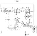
- FIG. 1 is a block diagram showing a hologram recording / reproducing apparatus of Example 1.
- FIG. FIG. 3 is a diagram for explaining a recording principle of the hologram recording / reproducing apparatus of Example 1. It is a figure explaining the reproduction
- FIG. FIG. 3 is a block diagram illustrating an opening position control circuit according to the first embodiment. It is a figure explaining SES in Example 1.
- FIG. It is a figure explaining the X-axis displacement of the opening part in Example 1.
- FIG. FIG. 3 is a block diagram illustrating a spindle error signal generation circuit and a spindle control circuit according to the first embodiment.
- FIG. 3 is a block diagram illustrating a radius error signal generation circuit and a radial direction conveyance control circuit according to the first embodiment.
- FIG. 3 is a block diagram illustrating a focus error signal generation circuit and a focus control circuit according to the first exemplary embodiment. It is a flowchart until the preparation of recording or reproduction
- FIG. 6 is a block diagram showing a hologram recording / reproducing apparatus of Example 3.
- FIG. 10 is a block diagram illustrating an opening position control circuit according to a third embodiment. 6 is a block diagram showing a hologram recording / reproducing apparatus in Example 4.
- FIG. 10 is a block diagram illustrating an opening position control circuit according to a fourth embodiment.
- FIG. 10 is a block diagram showing a hologram recording / reproducing apparatus in Example 5.
- FIG. 1 is a block diagram showing a recording / reproducing apparatus for a holographic recording medium that records and / or reproduces digital information using holography.
- the hologram recording / reproducing device 10 is connected to an external control device 91 via an input / output control circuit 90.
- the hologram recording / reproducing apparatus 10 receives an information signal to be recorded from the external control device 91 by the input / output control circuit 90.
- the hologram recording / reproducing device 10 transmits the reproduced information signal to the external control device 91 by the input / output control circuit 90.
- the hologram recording medium 1 in this embodiment has a disk shape and has an angle detection mark for detecting the rotation angle of the hologram recording medium 1.
- the hologram recording / reproducing apparatus 10 includes a pickup 11, a reproduction reference light optical system 12, a cure optical system 13, a rotation angle detection sensor 14, a radial position detection sensor 15, a focus detection sensor 17, a spindle motor 50, and a radial direction conveyance unit 51. , A Z stage 52 is provided.
- the spindle motor 50 has a medium attaching / detaching portion (not shown) that allows the hologram recording medium 1 to be attached to and detached from the rotation axis.
- the hologram recording medium 1 is configured to be rotatable by the spindle motor 50.
- the hologram recording medium 1 is configured to be movable in the radial direction by the radial transport unit 51 with reference to the position of the pickup 11.
- the hologram recording medium 1 is configured to be movable by a Z stage 52 in a direction parallel to the rotation axis (hereinafter referred to as a focus direction) with reference to the position of the pickup 11.
- the pickup 11 is used when information is recorded on the hologram recording medium 1 and when information recorded on the hologram recording medium 1 is reproduced.
- the hologram recording medium 1 is irradiated with reference light and signal light, and digital information is recorded on the recording medium using holography.
- the information signal to be recorded is sent to the spatial light modulator 212 (described later) in the pickup 11 by the controller 80 via the signal generation circuit 81, and the signal light is modulated by the spatial light modulator 212.
- the reproduction reference light optical system 12 When reproducing the information recorded on the hologram recording medium 1, the reproduction reference light optical system 12 generates a light wave that causes the reference light emitted from the pickup 11 to enter the hologram recording medium 1 in the direction opposite to that during recording. To do. Diffracted light reproduced by the reproduction reference light is detected by a photodetector 226 described later in the pickup 11, and a signal is reproduced by a signal processing circuit 82.
- Adjustment of the irradiation time of the reference light and the signal light with which the hologram recording medium 1 is irradiated is performed by the controller 80 transmitting a signal to the shutter control circuit 84, and the shutter control circuit 84 using the signal transmitted from the controller 80. Control is performed to open and close.
- the cure optical system 13 plays a role of generating a light beam used for pre-cure and post-cure of the hologram recording medium 1.
- Pre-curing is a pre-process for irradiating a predetermined light beam in advance before irradiating the reference light and signal light to the desired position when recording information at the desired position in the hologram recording medium 1.
- Post-cure is a post-process for irradiating a predetermined light beam after recording information at a desired position in the hologram recording medium 1 so that additional recording cannot be performed at the desired position.
- the light beam used for pre-cure and post-cure is preferably incoherent light, that is, light with low coherence.
- the light source drive circuit 83 supplies a predetermined light source drive current to the light sources in the pickup 11 and the cure optical system 13 in accordance with an instruction from the controller 80.
- the light source of the light source in the pickup 11 and the cure optical system 13 emits a light beam with a predetermined light amount.
- the pickup 11, the reproduction reference light optical system 12, the cure optical system 13, and the angle error detection optical system 30 may be simplified by combining some optical system configurations or all optical system configurations. .
- FIG. 2 shows a recording principle in an example of a basic optical system configuration of the pickup 11 and the reproducing reference light optical system 12 in the hologram recording / reproducing apparatus 10.
- the reproduction reference light optical system 12 includes an actuator 224 and a galvanometer mirror 225.
- the light beam emitted from the light source 201 passes through the collimator lens 202 and enters the shutter 203.
- the optical element 204 composed of, for example, a half-wave plate or the like, adjusts the light quantity ratio of p-polarized light and s-polarized light to a desired ratio.
- the light beam enters a PBS (Polarization Beam Splitter) prism 205.
- the light beam that has passed through the PBS prism 205 functions as signal light 206, and after the light beam diameter is expanded by the beam expander 208, the light beam passes through the phase mask 209, the relay lens 210, and the PBS prism 211 and passes through the spatial light modulator 212. Is incident on.
- the signal light 206 to which information is added by the spatial light modulator 212 is reflected by the PBS prism 211 and propagates through the opening 214 whose position can be adjusted by the relay lens 213 and the actuator 230.
- the opening 214 functions as a spatial filter. Thereafter, the signal light is condensed on the hologram recording medium 1 by the objective lens 215.
- the coordinate axes (x, y, z) are taken as shown in FIG.
- the y-axis is a direction perpendicular to the paper surface and is a direction perpendicular to the incident surface of the reference light.
- the x-axis is a direction parallel to the hologram recording medium 1 in the drawing, and the z-axis is a direction perpendicular to the hologram recording medium 1.
- These axes can be rephrased as follows.
- the x-axis is the moving direction of the hologram recording medium 1 when the spindle motor 50 is driven
- the y-axis is the moving direction of the hologram recording medium 1 when the radial transport unit 51 is driven
- the z-axis is driving the Z stage 52. This is the moving direction of the hologram recording medium 1 at the time.
- the actuator 230 in this embodiment can individually control each of the x axis, the y axis, and the z axis. That is, the position of the opening 214 functioning as a spatial filter can be controlled with three degrees of translation. This control is referred to as opening position control.
- the light beam reflected from the PBS prism 205 acts as reference light 207, which is set by the polarization direction conversion element 216 to a predetermined polarization direction according to recording or reproduction, and then passes through the mirror 217 and the galvanometer mirror 218.
- the galvanometer mirror 220 can adjust the angle in the paper surface by the actuator 221, and the incident angle of the reference light incident on the hologram recording medium 1 after passing through the lens 222 and the lens 223 can be set to a desired angle.
- an element that converts the wavefront of the reference light may be used instead of the galvanometer mirror.
- the galvanometer mirror 218 can adjust the angle in the direction perpendicular to the paper surface by the actuator 219, and the incident angle in the direction perpendicular to the paper surface of the reference light incident on the hologram recording medium 1 after passing through the lens 222 and the lens 223 is set to a desired angle. Can be set.
- the signal light 206 and the reference light 207 are incident on the hologram recording medium 1 so as to overlap each other, whereby an interference fringe pattern is formed in the hologram recording medium 1, and this pattern is written to the hologram recording medium 1. Record information with.
- the incident angle of the reference light incident on the hologram recording medium 1 can be changed by the galvanometer mirror 220, recording by angle multiplexing is possible.
- holograms corresponding to each incident angle are called pages, and a set of pages angle-multiplexed in the same area is called a book. To do.
- FIG. 3 shows a reproduction principle in an example of a basic optical system configuration of the pickup 11 and the reproduction reference light optical system 12 in the hologram recording / reproduction apparatus 10.
- the reference beam 207 is incident on the hologram recording medium 1 as described above, and the light beam transmitted through the hologram recording medium 1 is reflected by the galvanometer mirror 225 whose angle can be adjusted by the actuator 224.
- the reproduction reference light is generated.
- the diffracted light reproduced by the reproduction reference light propagates through the objective lens 215, the relay lens 213, and the opening 214. Thereafter, the diffracted light passes through the PBS prism 211 and enters the photodetector 226, and the recorded signal can be reproduced.
- an image sensor such as a CMOS image sensor or a CCD image sensor can be used as the photodetector 226.
- any element may be used as long as page data can be reproduced.
- the opening 214 has a photodetector (not shown). By providing this photodetector, it is possible to detect whether the diffracted light regenerated by the regenerative reference light is appropriately passing through the opening 214. That is, by using the signal of the photodetector provided in the opening 214, it is possible to detect the positional deviation of the opening 214 during reproduction.
- the position where signal light and / or reference light is irradiated (hereinafter referred to as the irradiation position) is determined by the position of the pickup 11 and is a position fixed to the apparatus.
- the spindle motor 50, the radial conveyance unit 51, and the Z stage 52 function as means for changing the position on the hologram recording medium 1 to which the signal light and / or reference light is irradiated.
- the rotation angle detection sensor 14 detects the rotation angle of the hologram recording medium 1 using an angle detection mark (not shown) provided on the hologram recording medium 1.
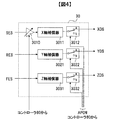
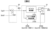
- the spindle error signal generation circuit 20 outputs the difference between the rotation angle target value Tgt ⁇ output from the controller 80 and the value det ⁇ detected by the rotation angle detection sensor 14 as a spindle error signal SES.
- the spindle control circuit 21 When changing the rotation angle irradiated with the signal light and / or the reference light, the spindle control circuit 21 generates a drive signal based on the SES and drives the spindle motor 50 via the spindle drive circuit 22. Thereby, the hologram recording medium 1 rotates, and the rotation angle at which the signal light and / or the reference light is irradiated can be controlled. This control is called spindle control.
- a scale 16 having a predetermined pattern is fixed to the movable part of the radial direction transport part 51.
- the radial position detection sensor 15 detects the position of the movable part of the radial direction transport part 51 using the scale 16.
- the radius error signal generation circuit 23 outputs the difference between the radius target value TgtR output from the controller 80 and the value detR detected by the radius position detection sensor 15 as a radius error signal RES.
- the radial transport control circuit 24 When changing the radial position irradiated with the signal light and / or the reference light, the radial transport control circuit 24 generates a drive signal based on the RES, and the radial transport unit 51 via the radial transport drive circuit 25. Drive.
- the hologram recording medium 1 is conveyed in the radial direction, and the radial position irradiated with the signal light and / or the reference light can be controlled. This control is called radial position control.
- the focus detection sensor 17 irradiates light on the surface of the hologram recording medium 1 and detects the reflected light to measure the distance to the hologram recording medium 1, that is, the focus position.
- the focus error signal generation circuit 26 outputs the difference between the predetermined value and the value detZ detected by the focus detection sensor 17 as the focus error signal FES.
- the focus control circuit 27 generates a drive signal based on the FES, and drives the Z stage 52 via the focus drive circuit 28. Thereby, the hologram recording medium 1 is conveyed in the focus direction, and the focus position where the signal light and / or the reference light is irradiated can be controlled. This control is referred to as focus control.
- the spindle control circuit 21, the radial direction conveyance control circuit 24, and the focus control circuit 27 return information to the controller 80 as to whether or not each drive has been completed.
- SES, RES, and FES are also input to the opening position control circuit 30.
- the opening position control circuit 30 generates a drive signal based on a command signal from the controller 80 and drives the actuator 230 in the pickup 11 via the opening position drive circuit 31. Thereby, the position of the opening 214 is controlled.
- the incident angle control circuit 70 controls the angles of the actuator 221 in the pickup 11 and the actuator 224 in the reproduction reference light optical system 12 via the incident angle drive circuit 71.
- the incident angle control circuit 70 receives a target angle Tgt ⁇ from the controller 80, an output signal of an angle detection sensor (not shown) provided in the actuator 221, and an output signal of an angle detection sensor (not shown) provided in the actuator 224. As input. If the output signal of the angle detection sensor provided in the actuator 221 is used, the incident angle at which the reference light reflected by the galvano mirror 220 is incident on the hologram recording medium 1 can be calculated, so that the incident angle becomes Tgt ⁇ . It can be controlled. The same applies to the actuator 224.
- the incident angle of the reference light incident on the hologram recording medium 1 is controlled.
- an optical encoder can be used as the angle detection sensor provided in the actuator 221, the actuator 224, and the actuator 219.
- the recording technique using the principle of angle multiplexing of holography tends to have a very small tolerance for deviation of the incident angle of the reference beam. Therefore, a mechanism for detecting the shift amount of the incident angle of the reference light is provided in the pickup 11 without using the angle detection sensor provided in the actuator 221, and the incident angle control circuit 70 inputs the output signal of the mechanism. As a configuration, a signal for use in controlling the incident angle of the reference light may be generated.
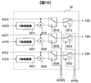
- the opening position control circuit 30 includes a displacement conversion gain 3010, an X axis compensator 3011, an X axis control switch 3012, a Y axis compensator 3021, a Y axis control switch 3022, a Z axis compensator 3031, and a Z axis control switch 3032.
- the displacement conversion gain 3010 receives SES, multiplies the gain k designated by the controller 80, and outputs a signal converted into displacement on the hologram recording medium 1. Since SES is a signal indicating the difference between the current rotation angle and the target rotation angle, when the hologram recording medium 1 rotates by a predetermined amount, the signal light emitted from the objective lens 215 and the amount of change in voltage of SES and The conversion coefficient k when converting to the displacement (unit: ⁇ m) of the irradiation position of the reference light is inversely proportional to the radius R. This is clear from the fact that even when the rotation angle is the same, the drawn arc becomes longer as the radius increases.
- the controller 80 designates the gain k of the displacement conversion gain 3010 from the information on the radius R.
- the X-axis compensator 3011 performs gain and phase compensation on the output signal of the displacement conversion gain 3010, and outputs a drive signal for controlling the position of the opening 214 in the X-axis direction.
- the X-axis compensator 3011 can be configured as a digital filter including an integrator, for example.
- the X-axis control switch 3012 switches whether to output the output signal of the X-axis compensator 3011 according to the control signal APON from the controller 80, and outputs it as an XDS signal.
- XDS is supplied to the actuator 230 via the opening position drive circuit 31, and the position of the opening 214 in the X-axis direction is controlled.
- the SES is input to the X-axis compensator 3011 as a target trajectory. Therefore, by appropriately designing the gains of the variable gain 3010 and the X-axis compensator 3011, the X-axis displacement of the opening 214 can be controlled by ⁇ times the displacement indicated by the SES.
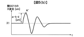
- FIG. 5A shows SES
- FIG. 5B shows the X-axis displacement of the opening 214.
- SES is an electrical signal
- the unit is volts.
- d [V] be the difference between the voltage at point A and the value before application of external vibration.
- the amount of vibration at point A due to external vibration is k ⁇ d [ ⁇ m]. That is, the displacement indicated by the displacement of the SES of d [V] is k ⁇ d [ ⁇ m].
- the waveform can be approximately equal to the waveform.
- X1 be the X-axis displacement of the opening 214 before application of external vibration.
- a ′ a point corresponding to the point A in SES.
- the gain of the X-axis compensator 3011 is designed so that the difference between the displacement at the point A ′ and the displacement before application of external vibration is ⁇ ⁇ (k ⁇ d) [ ⁇ m].
- the opening 214 moves in the X-axis direction by a displacement that is ⁇ times the displacement amount.
- the description of whether the SES polarity matches the X axis is omitted.
- the polarity of SES is opposite to that of the X axis, and actually, the opening 214 is displaced in the opposite direction to the direction of displacement of the hologram recording medium 1 indicated by the displacement of SES. The reason for this will be described later.
- the Y-axis compensator 3021 performs gain and phase compensation for the RES, and outputs a drive signal for controlling the position of the opening 214 in the Y-axis direction.
- the Y-axis compensator 3021 can be configured as a digital filter including an integrator, for example.
- the gain of the Y-axis compensator 3021 is designed so that the opening 214 moves in the Y-axis direction by a displacement ⁇ times the displacement amount.
- the Z-axis compensator 3031 performs gain and phase compensation on the EES, and outputs a drive signal for controlling the position of the opening 214 in the Z-axis direction.
- the Z-axis compensator 3031 can be configured as a digital filter including an integrator, for example.
- the Z-axis compensator when the hologram recording medium 1 is displaced in the Z-axis direction by external vibration, the Z-axis compensator so that the opening 214 moves in the Z-axis direction by a displacement ⁇ times the displacement amount.
- a gain of 3031 is designed.
- the Y-axis control switch 3022 switches whether to output the output signal of the Y-axis compensator 3021 according to the control signal APON from the controller 80, and outputs it as a YDS signal.
- the Z-axis control switch 3032 switches whether to output the output signal of the Z-axis compensator 3031 according to the control signal APON from the controller 80 and outputs it as a ZDS signal.
- YDS and ZDS are supplied to the actuator 230 via the opening position drive circuit 31, and the positions of the opening 214 in the Y-axis and Z-axis directions are controlled.
- the X-axis control switch 3012, the Y-axis control switch 3022, and the Z-axis control switch 3032 output the output signal of the compensator for each axis when the APON signal is High, and turn off the output when the APON signal is Low. .
- the spindle error signal generation circuit 20 includes a subtractor 2001.
- the subtracter 2001 subtracts Tgt ⁇ and Det ⁇ , and outputs the value of (Tgt ⁇ Det ⁇ ) as SES.
- the spindle control circuit 21 includes a spindle controller 2101, a spindle output control switch 2102, and a spindle control determination circuit 2103.
- the spindle controller 2101 performs gain and phase compensation for the SES, and outputs a drive signal for controlling the rotation angle of the spindle motor 50.
- the subtractor 2001 and the spindle controller 2101 constitute a feedback control system for controlling the rotation angle of the spindle motor 50. Further, the target value of the feedback control system is Tgt ⁇ , and control is performed so that the rotation angle of the spindle motor 50 becomes Tgt ⁇ .
- the spindle output control switch 2102 switches whether to output the output signal of the spindle controller 2101 according to the control signal SPON from the controller 80, and outputs it as an SPD signal.
- the spindle output control switch 2102 outputs the output signal of the spindle controller 2101 when the SPON signal is High, and turns off the output when the SPON signal is Low.
- the spindle control determination circuit 2103 receives the SES, determines whether or not the rotation angle of the hologram recording medium 1 is near the angle command value Tgt ⁇ , and outputs it as a SPOK signal. When the rotation angle of the hologram recording medium 1 is a value in the vicinity of the angle command value Tgt ⁇ , the SPOK signal is assumed to be High.
- the spindle control determination circuit 2103 can be realized, for example, by measuring an elapsed time after the SES becomes a predetermined threshold value or less and making a determination by continuing the measurement time for a predetermined time or more.
- the SPOK signal that is the determination result is input to the controller 80. With the above configuration, the spindle control determination circuit 2103 functions as a circuit for determining convergence of spindle control.
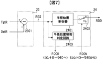
- the radius error signal generation circuit 23 includes a subtracter 2301.
- the subtracter 2301 subtracts TgtR and DetR and outputs the value of (TgtR ⁇ DetR) as RES.
- the radial direction conveyance control circuit 24 includes a radial position controller 2401, a radial position output control switch 2402, and a radial position control determination circuit 2403.
- the radial position controller 2401 performs gain and phase compensation for the RES, and outputs a drive signal for controlling the position of the movable part of the radial transport part 51.
- the subtractor 2301 and the radial position controller 2401 constitute a feedback control system for controlling the position of the movable part of the radial transport unit 51. Further, the target value of the feedback control system is TgtR, and the control is performed so that the position of the movable portion of the radial transport unit 51 is TgtR.
- the radial position output control switch 2402 switches whether to output the output signal of the radial position controller 2401 according to the control signal RDON from the controller 80, and outputs it as an RDDD signal.
- the radial position output control switch 2402 outputs the output signal of the radial position controller 2401 when the RDON signal is High, and turns off the output when the RDON signal is Low.
- the radial position control determination circuit 2403 receives RES, determines whether or not the position of the movable part of the radial direction transport part 51 is a value near the position command value TgtR, and outputs it as an RDOK signal. In addition, when the position of the movable part of the radial direction conveyance part 51 is a value in the vicinity of the position command value TgtR, the RDOK signal is assumed to be High.
- the radial position control determination circuit 2403 can be realized, for example, by measuring an elapsed time after the RES becomes a predetermined threshold value or less and making a determination by continuing the measurement time for a predetermined time or more.
- the RDOK signal that is the determination result is input to the controller 80. With the above configuration, the radial position control determination circuit 2403 functions as a circuit that determines the convergence of the radial position control.
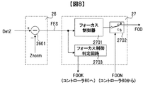
- the focus error signal generation circuit 26 includes a subtracter 2601.
- the subtractor 2601 performs subtraction between DetZ and a predetermined value Znorm, and outputs the value of (DetZ ⁇ Zorm) as FES.
- the focus control circuit 27 includes a focus controller 2701, a focus output control switch 2702, and a focus control determination circuit 2703.
- the focus controller 2701 compensates the gain and phase for the FES and outputs a drive signal for controlling the focus position of the hologram recording medium 1.
- the subtractor 2601 and the focus controller 2701 constitute a feedback control system for controlling the focus position of the hologram recording medium 1.
- the target value of the feedback control system is Znorm, and control is performed so that the distance from the focus detection sensor 17 to the hologram recording medium 1 becomes Znorm.
- the focus output control switch 2702 switches whether to output the output signal of the focus controller 2701 according to the control signal FOON from the controller 80, and outputs it as an FOD signal.
- the focus output control switch 2702 outputs the output signal of the focus controller 2701 when the FOON signal is High, and turns off the output when the FOON signal is Low.
- the focus control determination circuit 2703 receives the FES, determines whether or not the focus position of the hologram recording medium 1 is a value near Znorm, and outputs it as a FOOK signal. It is assumed that the FOOK signal becomes High when the focus position of the hologram recording medium 1 is a value near Znorm.
- the focus control determination circuit 2703 can be realized, for example, by measuring an elapsed time after the FES becomes equal to or less than a predetermined threshold and making a determination by continuing the measurement time for a predetermined time or more.
- the FOOK signal that is the determination result is input to the controller 80.
- the focus control determination circuit 2703 functions as a circuit that determines convergence of focus control.
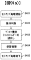
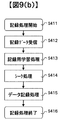
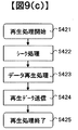
- FIG. 9 shows a flowchart of recording and reproduction in the hologram recording / reproducing apparatus 10.
- processing relating to recording / reproduction using holography in particular will be described.
- a process from when the hologram recording medium 1 is inserted into the hologram recording / reproducing apparatus 10 until preparation for recording or reproduction is completed is referred to as a setup process.
- the process of recording information on the hologram recording medium 1 from the ready state is called a recording process
- the process of reproducing information recorded on the hologram recording medium 1 from the ready state is called a playback process.
- FIG. 9A shows a flowchart of the setup process
- FIG. 9B shows a flowchart of the recording process
- FIG. 9C shows a flowchart of the reproduction process.
- the hologram recording / reproducing apparatus 10 determines whether, for example, the inserted medium is a medium for recording or reproducing digital information using holography. The medium is determined (step S402).
- the hologram recording / reproducing apparatus 10 reads control data provided on the hologram recording medium 1 (step S403). For example, information on the hologram recording medium 1 and information on various setting conditions at the time of recording and reproduction are obtained.
- the hologram recording / reproducing apparatus 10 After reading the control data, the hologram recording / reproducing apparatus 10 performs various adjustments according to the control data and learning processing related to the pickup 11 (step S404). Thereby, the hologram recording / reproducing apparatus 10 completes preparation for recording or reproduction, and ends the setup process (step S405).
- the hologram recording / reproducing device 10 receives the recording data from the external control device 91 (step S412), and the signal generation circuit 81 generates two-dimensional data corresponding to the data.
- the light is sent to the spatial light modulator 212 in the pickup 11.
- the holographic recording / reproducing apparatus 10 learns for various recordings such as optimization of the power of the light source 201 and optimization of the exposure time by the shutter 203 so that high quality information can be recorded on the holographic recording medium 1. Processing is performed in advance (step S413).
- the hologram recording / reproducing apparatus 10 controls the spindle motor 50 and the radial transport unit 51 using the spindle control circuit 21 and the radial transport control circuit 24.
- the hologram recording medium 1 is positioned so that the light beam irradiated from the pickup 11 and the cure optical system 13 is irradiated to a predetermined position of the hologram recording medium 1.
- the address information is reproduced, and it is confirmed whether the irradiation position of the light beam is positioned at a position corresponding to the address information.
- the spindle control circuit 21 and the radial direction conveyance control circuit 24 are used again to calculate the spindle. The operation of controlling and positioning the motor 50 and the radial conveyance unit 51 is repeated.
- the hologram recording / reproducing apparatus 10 performs a data recording process for recording data to be recorded as a hologram on the hologram recording medium 1 (step S415).
- the light irradiation angle is changed by a predetermined angle, and a hologram different from the already recorded hologram is stored to form a book.
- the recording process is terminated (step S416). Note that data recorded in the hologram storage medium 1 may be verified as necessary.
- the hologram recording / reproduction apparatus 10 first uses the spindle control circuit 21 and the radial direction conveyance control circuit 24 in the seek process (step S422), and uses the pickup 11 and the reproduction reference light optical system.
- the hologram recording medium 1 is positioned so that the light beam irradiated from 12 is irradiated to a predetermined position of the hologram recording medium 1.
- the address information is reproduced, and it is confirmed whether the irradiation position of the light beam is positioned at a position corresponding to the address information.
- the spindle control circuit 21 and the radial direction conveyance control circuit 24 are used again to calculate the spindle. The operation of controlling and positioning the motor 50 and the radial conveyance unit 51 is repeated.
- the hologram recording / reproducing apparatus 10 emits the reference beam 207 from the pickup 11 to the hologram storage medium 1.
- the diffracted light reproduced by the reference light is detected as two-dimensional data by the photodetector 226, and the signal processing circuit 82 processes the two-dimensional data to read out the data recorded on the hologram recording medium 1 (step). S423).
- the hologram recording / reproducing device 10 transmits the read data to the external control device 91 as reproduced data (step S424). When transmission of the reproduction data is completed, the reproduction process is terminated (step S425).
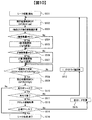
- the seek process S414 in this embodiment will be described with reference to the flowchart of FIG. Note that the same flowchart is applied to the seek process S422.
- the radius r and the rotation angle ⁇ are parameters.
- the drive shaft having the radius r is referred to as r-axis
- the drive shaft having the rotation angle ⁇ is referred to as ⁇ -axis.
- the movement of the hologram recording medium 1 in the r-axis direction and the ⁇ -axis direction is performed by the spindle motor 50 and the radial direction conveyance unit 51.
- step S501 the controller 80 sets the APON signal to low and turns off the opening position control (step S502). Subsequently, the difference between the coordinates (r, ⁇ ) of the book where the hologram of the target address is located and the current irradiation position is calculated, and the movement amount is calculated for the r axis and the ⁇ axis (step S503). Next, it is determined whether the amount of movement in the r-axis direction is other than zero (step S504). If the amount of movement in the r-axis direction is other than zero (Yes in step S504), the target radius TgtR is changed and movement in the r-axis direction is started (step S505). After step S505, the process proceeds to step S506 described later. If the amount of movement in the r-axis direction is zero (No in step S504), the process proceeds to step S506 without performing step S505.
- step S506 it is determined whether the amount of movement in the ⁇ -axis direction is other than zero. If the movement amount in the ⁇ -axis direction is other than zero (Yes in step S506), the target rotation angle Tgt ⁇ is changed and movement in the ⁇ -axis direction is started (step S507). After step S507, the process proceeds to step S508 described later. If the amount of movement in the ⁇ -axis direction is zero (No in step S506), the process proceeds to step S508 without performing step S507.
- step S508 it is determined whether or not the movement of the r-axis direction, the ⁇ -axis direction, and the focus axis has been completed.
- the focus control is always controlled. Therefore, when the position of the hologram recording medium 1 is changed in step S505 or step S507 and the focus position is changed due to the surface shake of the hologram recording medium 1, the focus position is adjusted by the focus control circuit 27.
- step S508 If it is determined that the movement has not been completed (No in step S508), the process returns to step S508 again. That is, if any one of the RDOK signal, the SPOK signal, and the FOOK signal is at a low level, it is not determined that the movement has been completed, and the operation waits until all the three signals simultaneously become a high level. It becomes.
- step S508 If it is determined that the movement has been completed (Yes in step S508), the controller 80 sets the APON signal to high to turn on the opening position control (step S509).
- step S510 it is determined whether or not the seek process during reproduction is performed. If it is not the seek process at the time of reproduction (No in step S510), the process proceeds to step S516 described later, and the seek process is terminated. In the case of seek processing at the time of reproduction (Yes in step S510), the seek processing is not finished with this, and finally, the address information obtained by reproducing the recorded hologram is used to set the target address. Continue seeking until it is correctly positioned. This is because the seek process at the time of recording is a seek process to an unrecorded portion in the hologram recording medium 1, and address information cannot be obtained.
- step S510 In the case of seek processing during playback (Yes in step S510), the first page in the book recorded at the coordinates represented by the r-axis and ⁇ -axis is played back, and the page concerned Is reproducible (step S511). If reproduction is impossible (No in step S511), it is confirmed that the hologram recording medium 1 cannot be accurately moved by the spindle motor 50 and the radial direction conveyance unit 51 from step S502 to step S509. means. Therefore, based on the predetermined retry parameter, the r-axis and ⁇ -axis retry values are calculated (step S512), and the process returns to step S502. As a result, seek processing for moving to the vicinity of the positioning is performed.
- step S511 If the hologram can be reproduced (Yes in step S511), the address information included in the reproduced hologram is acquired (step S513). Subsequently, it is determined whether or not the acquired address is a target address (step S514). If the acquired address is not the target address (No in step S514), it means that positioning has not been performed correctly. Therefore, the difference between the coordinates (r, ⁇ ) of the acquired address and the coordinates (r, ⁇ ) of the target address is calculated (step S515), and the process returns to step S502. Thereby, a seek process based on the address information of the hologram is performed.
- step S5136 If the acquired address is the target address (Yes in step S514), the seek process is terminated (step S516).
- the hologram recording medium 1 Since the hologram recording medium 1 has a large inertia, it is difficult to increase the control band for spindle control, radial position control, and focus control for controlling the position of the hologram recording medium 1. For this reason, once the hologram recording medium 1 starts to vibrate, it is difficult to converge the vibration at high speed.
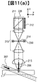
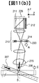
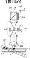
- FIG. 11 shows the light beam through which the signal light 206 passes, the reference light 207, and the hologram recording medium 1 during recording.
- the numbers in the figure are the same as those in FIG.
- FIG. 11A shows a case where the hologram recording medium 1 is at the design center position.
- the light beam exiting the spatial light modulator 212 is condensed at the position of the opening 214 due to the lens effect of the relay lens 213.
- FIG. 11B shows a case where the hologram recording medium 1 is displaced in the negative direction of the y-axis due to external vibration or the like in this embodiment, and FIG. The cases of displacement in the positive direction of the z-axis due to factors are shown.
- a light beam when the actuator 230 is displaced in the positive direction of the y-axis will be described with reference to FIG.
- the position where the signal light 206 is collected by the objective lens 215 is as shown in FIG. It moves in the negative direction of the y-axis as indicated by point B. That is, when the actuator 230 is displaced in the positive direction of the y axis, the position of the hologram formed by the interference between the signal light 206 and the reference light 207 moves in the negative direction of the y axis.
- the actuator 230 is displaced by a predetermined amount in the positive y-axis direction as shown by an arrow C in FIG.
- the influence of the displacement due to external vibration can be canceled.
- the actuator 230 is displaced by a predetermined amount in the positive direction of the z-axis as indicated by an arrow F in FIG.
- the influence of the displacement due to the external vibration can be canceled.
- the hologram recording medium 1 is irradiated with both the signal light 206 and the reference light 207 to record the hologram.
- the reference light 207 is irradiated onto the hologram recording medium 1 to generate diffracted light, thereby generating the hologram.
- reproduction In other words, by considering the propagation direction of the signal light 206 in FIG. Therefore, even when the hologram is reproduced, the influence of the displacement due to the external vibration can be canceled by displacing the actuator 230.
- the opening 214 moves in the X-axis direction by a displacement that is ⁇ times the displacement amount.
- the opening 214 moves in the Y-axis direction by a displacement that is ⁇ times the displacement
- the opening 214 moves in the Y-axis direction by a displacement ⁇ times the displacement amount.
- ⁇ , ⁇ , and ⁇ are parameters determined by the design of the optical system, and values calculated from the design information of the optical system are used.
- the X axis and the Y axis are opposite to the displacement direction of the hologram recording medium 1, and the Z axis is the same direction as the displacement direction of the hologram recording medium 1.
- FIG. 10 which is a flowchart in the present embodiment
- the position control of the actuator 230 is turned on when the seek process for the hologram recording medium 1 is completed. Therefore, when a disturbance such as vibration or impact is applied from the outside of the apparatus after the positioning is completed, the disturbance is detected by SES, RES, and FES, and the position of the opening 214 is controlled by the opening position control circuit 30. As a result, the influence of the displacement of the hologram recording medium 1 due to the disturbance can be canceled as described with reference to FIG.
- the opening position control by the actuator 230 is off until it is determined in step S508 that the movement has been completed.
- the movable range of the actuator 230 is limited. That is, if the opening position control by the actuator 230 is turned on while the hologram recording medium 1 is moving, for example, a very large value can be generated immediately after the movement as SER. The actuator 230 tries to be displaced by a value multiplied by ⁇ to this value. However, if it exceeds the movable range, the follow-up control cannot be performed, and the actuator 230 may be destroyed. For this reason, it is desirable to turn off the opening position control by the actuator 230 while the hologram recording medium 1 is moving.
- the first embodiment will be described using SES as an example, and is configured to perform two controls of spindle control and opening position control of the X axis using a common signal called SES.
- SES spindle control
- the present embodiment is an embodiment that focuses on this point and improves the stability of control.
- FIG. 1 is a block diagram of the first embodiment.
- the difference in configuration from the first embodiment is the internal configuration of the spindle control circuit 21 and the opening position control circuit 30.
- a low-pass filter (LPF) 2104 is added to the spindle control circuit 21.
- the low-pass filter 2104 receives the SES and attenuates the high frequency component of the SES.
- the output signal of the low pass filter 2104 is input to the spindle controller 2101.
- a high pass filter (HPF) 3013 is added to the opening position control circuit 30.
- HPF high pass filter
- a high-pass filter 3013 receives SES and attenuates low frequency components of ES.
- the output signal of the high-pass filter 3013 is input to the X-axis compensator 3011 via the displacement conversion gain 3010.
- the spindle controller 2101 and the X-axis compensator 3011 are configured to perform control using a common SES.
- the spindle control controls the hologram recording medium 1 with respect to the SES variation of the same frequency component, while the opening position control controls the opening 214.
- the stability of the control is lowered and it takes time until both the two controls converge.
- the spindle control is performed based on the signal obtained by extracting the low-frequency component of the SES by the low-pass filter 2104, and the opening position control is performed based on the signal obtained by extracting the high-frequency component of the SES by the high-pass filter 3013. It was set as the structure which controls. As a result, the time can be shortened until both of the two controls converge.
- the low-pass filter 2104 is provided.
- the low-pass filter 2104 is not always essential. This is because the inertia of the hologram recording medium 1 is large and the band of the spindle control system cannot be increased compared to the opening position control. For this reason, since the frequency band to which the spindle control system responds is inevitably low, a configuration in which the low-pass filter 2104 is deleted from FIG. 12 is also conceivable. The same applies to the radial position control and the focus control since the inertia to be controlled is common.
- the opening position is controlled based on the result of detecting the displacement of the hologram recording medium 1.
- the opening position is controlled using a signal indicating the positional deviation of the opening 214 generated from the diffracted light during reproduction.
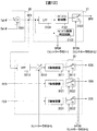
- FIG. 13 is a block diagram showing a recording / reproducing apparatus for a hologram recording medium for recording and / or reproducing digital information using holography.
- the same number is attached
- the difference in configuration from the first embodiment is that an internal configuration of the opening position control circuit 30 and a reproduction opening error signal generation circuit 32 are provided.
- the reproduction opening error signal generation circuit 32 uses a signal from the photodetector provided in the opening 214 to generate a signal AXES indicating the positional deviation in the X-axis direction with respect to the position of the opening 214 during reproduction.
- a signal AYES indicating a positional shift and a signal AZES indicating a positional shift in the Z-axis direction are generated.
- the opening position error signal at the time of reproduction is named as a general term for AXES, AYES, and AZES.
- AXES, AYES, and AZES are input to the opening position control circuit 30.
- an X-axis opening position error signal selector 3014 receives a signal AESEN indicating whether or not the reproduction opening position error signal is a valid period.
- the controller 80 receives a signal AESEN indicating whether or not the reproduction opening position error signal is a valid period.
- the AESEN signal is at a high level, it indicates that the reproduction opening position error signal (AXES, AYES, AZES) is a valid period.
- the X-axis opening position error signal selection selector 3014 receives the output signal of the displacement conversion gain 3010 and AXES, outputs AXES when the AESEN signal is high level, and outputs the displacement conversion gain 3010 when the AESEN signal is low level. Output a signal.
- the Y-axis opening position error signal selector 3024 receives RES and AYES, outputs AYES when the AESEN signal is high level, and outputs RES when the AESEN signal is low level.
- the Z-axis opening position error signal selector 3034 receives FES and AZES, outputs AZES when the AESEN signal is high level, and outputs FES when the AESEN signal is low level.
- the opening position control when the reproduction opening position error signal is not valid (when the AESEN signal is at a low level), the opening position control is the same as in the first embodiment. On the other hand, when the reproduction opening position error signal is valid (when the AESEN signal is at a high level), the opening position control is performed based only on the reproduction opening position error signal.
- the opening position can be controlled based on the information on the positional deviation generated from the diffracted light during reproduction, the influence of the displacement of the hologram recording medium 1 when disturbance such as vibration is applied during reproduction. Can be canceled and the reproduction performance can be further improved. Further, since the opening position control is performed based on the result of detecting the displacement of the hologram recording medium 1 at the time of recording, the influence of the displacement of the hologram recording medium 1 when a disturbance such as vibration is applied at the time of recording can be canceled.
- the opening position is controlled based on the result of detecting the displacement of the hologram recording medium 1.
- the acceleration applied to the hologram recording apparatus 10 is detected, and the opening position is controlled based on the detected acceleration.
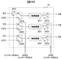
- the present embodiment will be described as a modification of the third embodiment.
- FIG. 15 is a block diagram showing a recording / reproducing apparatus for a holographic recording medium for recording and / or reproducing digital information using holography.
- the same number is attached
- the difference in configuration from the third embodiment is that the internal configuration of the opening position control circuit 30 and the acceleration detection sensor 18 are provided.
- the acceleration detection sensor 18 individually measures accelerations in the X-axis, Y-axis, and Z-axis directions applied to the hologram recording apparatus 10, and outputs voltages proportional to the respective axis directions as ACX, ACY, and ACZ signals.
- the X-axis compensator 3011 receives the AXES signal indicating the positional deviation in the X-axis direction of the opening 214 during reproduction and outputs a drive signal.
- the X-axis adder 3015 outputs a signal obtained by adding the output signal of the X-axis compensator 3011 and the ACCX signal indicating the detected acceleration in the X-axis direction.
- the X-axis acceleration control selector 3016 receives the ACCX signal and the output signal of the X-axis adder 3015, outputs ACCX when the AESEN signal is low, and outputs the X-axis adder 3015 when the AESEN signal is high. Output a signal.
- the opening position control is performed based on the ACCX signal indicating the detected acceleration in the X-axis direction.
- the reproduction opening position error signal is valid (when the AESEN signal is at a high level)
- opening position control based on the reproduction opening position error signal and the ACCX signal is performed.
- the Y-axis compensator 3021 receives the AYES signal, and the output signal and the ACCY signal are added by the Y-axis adder 3025.
- the Y-axis acceleration control selector 3016 receives the ACCY signal and the output signal of the Y-axis adder 3025, outputs ACCY when the AESEN signal is low level, and outputs the Y-axis adder 3025 when the AESEN signal is high level. Output a signal.
- the Z-axis compensator 3031 receives the AZES signal, and the output signal and the ACCZ signal are added by the Z-axis adder 3035.
- the Z-axis acceleration control selector 3036 receives the ACCZ signal and the output signal of the Z-axis adder 3035, outputs ACCZ when the AESEN signal is low level, and outputs the Z-axis adder 3035 when the AESEN signal is high level. Output a signal.
- the acceleration applied to the hologram recording / reproducing apparatus 10 can be detected, and the opening position can be controlled based on the detected acceleration.
- the acceleration feedforward control is additionally performed on the feedback control system based on the reproduction opening position error signal.
- robustness against disturbance can be improved.
- the present embodiment has been described as a modification of the third embodiment where a reproduction opening position error signal is used.
- the reproduction opening position error signal is not used, the same control as when the reproduction opening position error signal is not valid (when the AESEN signal is at the low level) may be performed. That is, the opening position control based on the acceleration can be performed by generating the drive signal based on the detected acceleration.
- the direction of displacement by the spindle motor 50, the radial transport unit 51, and the Z stage 52 that changes the position on the hologram recording medium 1 irradiated with the signal light and / or the reference light is set at the opening 214.
- the configuration coincides with the drive shaft (x, y, z).
- a present Example is a modification in case this does not correspond.
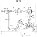
- FIG. 17 shows an optical system configuration of the pickup 11 and the reproduction reference light optical system 12 in the hologram recording / reproduction apparatus 10 in the present embodiment.
- the signal light 206 collected by the objective lens 215 with respect to the hologram recording medium 1 is incident at an angle rather than a right angle. That is, the hologram recording medium 1 is installed obliquely with respect to the first embodiment.
- the components of the pickup 11 and the reproducing reference beam optical system 12 and the components of the hologram recording / reproducing apparatus 10 are the same as those in the first embodiment.
- the direction of change of the irradiation position by the spindle motor 50 is the ⁇ axis
- the direction of change of the irradiation position by the radial transport unit 51 is the r axis
- the direction of change of the irradiation position by the Z stage 52 is the f axis.
- the position of the opening 214 in this embodiment can be changed along the three drive axes (x, y, z). Further, the position of the hologram recording medium 1 can be changed along the three drive axes (r, ⁇ , f).
- the actuator 230 capable of adjusting the position of the opening 214 in this embodiment is composed of an electromagnetic actuator and a stepping motor (both not shown), and (x, z) movement in two axes by the electromagnetic actuator, and y by the stepping motor.
- the axis is moved.
- the movement of the opening 214 in the y-axis direction takes longer than the movement in the x-axis direction and the movement in the z-axis direction due to the configuration.
- the frequency of changing the irradiation position in the direction of the ⁇ axis by the spindle motor 50 is greater in the radial direction conveyance unit 51.
- the frequency of changing the irradiation position in the r-axis direction is set higher.
- the spindle motor 50 is moved a plurality of times to record a hologram in an arc shape with the same radius on the hologram recording medium 1, and then the radial transport unit 51 is driven to change the radius again.
- the rotation motor 50 is driven to drive the hologram recording medium 1 at a speed higher than the speed at which the radial conveyance unit 51 is driven to move the hologram recording medium 1 by the distance between the books.
- the speed of moving by the distance between books is faster.
- the hologram recording medium 1 is in contact with the rotary motor 50 and rotates integrally with the rotary shaft. For this reason, the load applied to the rotary motor 50 is only the hologram recording medium 1.
- the radial transport unit 51 since the radial transport unit 51 is in contact with the rotary motor 50, the load applied to the radial transport unit 51 is the rotary motor 50 and the hologram recording medium 1. That is, the radial conveyance unit 51 is driven in a state where the weight of the rotary motor 50 is applied. As a result, the above speed difference occurs.
- the frequency of changing the irradiation position in the ⁇ -axis direction by the spindle motor 50 is greater by the radial transport unit 51.
- the transfer speed of recording or reproduction can be performed at a high speed.
- the opening 214 may be moved in the x-axis direction and the z-axis direction.
- the opening 214 must be moved in the r-axis direction. Since the x-axis direction and the z-axis direction that can be driven by the electromagnetic actuator are shorter, the movement in the ⁇ -axis direction is more advantageous from the viewpoint of the movement time of the opening 214 accompanying the change of the irradiation position.
- the r-axis coincides with the drive axis (y-axis) having the longest movement time among the three drive axes of the opening 214.
- a series of information recording processing or a series of information on the hologram recording medium 1 is performed.
- the accumulated time of the movement time of the opening 214 can be minimized.
- the three drive axes (x, y, z) of the opening 214 do not coincide with the three drive axes (r, ⁇ , f) that change the irradiation position of the hologram recording medium 1.
- the movement direction (r-axis) by the radial transport unit 51 that can move only at the lowest speed in moving the irradiation position and one of the three drive shafts of the opening 214 (more specifically, three of the opening 214) It is desirable to match the drive axis having the longest movement time among the two drive axes. Thereby, the transfer speed of recording or reproduction can be performed at high speed.
- the spindle control circuit 21, the radial conveyance control circuit 24, the focus control circuit 27, and the opening position control circuit 30 in the above embodiment are control circuits that constitute a feedback control system as described with reference to FIG. .
- it may be a control circuit that constitutes a two-degree-of-freedom control system having feed-forward control in addition to feedback control.
- the radial transport unit 51 in the first embodiment is used as a mechanism for controlling the light beam irradiated from the pickup 11 and the cure optical system 13 to be irradiated to a predetermined position of the hologram recording medium.
- the hologram recording medium 1 is transported.
- the mechanism for sharing the irradiation position of the light beam is not limited to this.
- the hologram recording medium may be fixed, and an optical system including the pickup 11 and the cure optical system 13 may be conveyed.
- the mechanism for transporting the optical system functions as means for changing the position on the hologram recording medium 1 to which the signal light and / or the reference light is irradiated.
- the present invention can be similarly applied if a sensor that detects the position of the optical system is used instead of detecting the position of the hologram recording medium 1.
- the rotation angle detection sensor 14, the radial position detection sensor 15, and the focus detection sensor 17 in the above embodiment detect information related to the position of the hologram recording medium 1 with reference to the position of the optical system including the pickup 11.
- these sensors can be rephrased as a detection unit capable of detecting information on the relative positions of the detection units and the hologram recording medium 1.
- Each detection unit can also be referred to as a detection unit that can detect information on the relative position between the objective lens 215 and the hologram recording medium 1.
- the present invention can be applied to a hologram recording / reproducing apparatus that uses signal light or diffracted light as parallel light without using the objective lens 215.
- the optical system and the hologram recording medium 1 can be used.
- it can be referred to as a detection unit capable of detecting information on relative positions.
- the detection unit capable of detecting information related to the relative position may not necessarily detect the position directly.
- a sensor for detecting the relative speed between the optical system and the hologram recording medium 1 may be provided, the position may be calculated by integrating the detected speed, and the position may be replaced with the position in the above embodiment.
- a sensor for detecting acceleration may be provided, the position may be calculated from the detected acceleration, and the position may be replaced with the position of the above-described embodiment.
- the position may be directly added to the control circuit in the opening position control circuit 30 without being converted into the position.
- the information on the detected position does not necessarily have to be converted into the position, and is characterized in that the position of the opening 214 is controlled based on the information on the detected position.
- the opening 214 has three drive shafts (x, y, z) by the actuator 230, but may have only one of the drive shafts.
- the opening 214 may be configured to be driven only in the x axis.
- the hologram recording / reproducing apparatus 10 of the present invention is configured to perform both information recording and information reproducing.
- the present invention can be similarly applied to a recording-dedicated apparatus or a reproduction-dedicated apparatus. It is.
- the photodetector 226 is unnecessary, and in the case of a reproduction-only device, the spatial light modulator 212 is not required.
- the light passing through the opening 214 whose position is changed by opening position control is signal light in the case of a recording-only device, and diffracted light in the case of a reproduction-only device.
- the present invention is not limited to the above-described embodiments, and includes various modifications in addition to the above-described modifications.
- the above-described embodiments have been described in detail for easy understanding of the present invention, and are not necessarily limited to those having all the configurations described.
- a part of the configuration of one embodiment can be replaced with the configuration of another embodiment, and the configuration of another embodiment can be added to the configuration of one embodiment.
- each of the above-described configurations, functions, processing units, processing means, and the like may be realized by hardware by designing a part or all of them with, for example, an integrated circuit.
- Each of the above-described configurations, functions, and the like may be realized by software by interpreting and executing a program that realizes each function by the processor.
- Information such as programs, tables, and files that realize each function can be stored in a memory, a hard disk, a recording device such as an SSD (Solid State Drive), or a recording medium such as an IC card, an SD card, or a DVD.
- control lines and information lines indicate what is considered necessary for the explanation, and not all the control lines and information lines on the product are necessarily shown. Actually, it may be considered that almost all the components are connected to each other.
- SYMBOLS 1 DESCRIPTION OF SYMBOLS 1 ... Hologram recording medium 10 ... Hologram recording / reproducing apparatus 11 ... Pickup 12 ... Reproduction reference light optical system 13 ... Cure optical system 14 ... Rotation angle detection sensor 15 ... Radius position detection sensor 17 ... Focus detection sensor 30 ... Opening position control circuit DESCRIPTION OF SYMBOLS 31 ... Opening position drive circuit 50 ... Spindle motor 51 ... Radial direction conveyance part 52 ... Z stage 201 ... Light source 206 ... Signal light 207 ... Reference light 212 ... Spatial light modulator 214 ... Opening part 215 ... Objective lens 226 ... Optical detector 230 ... Actuator 3010 ... Displacement conversion gain 3011 ... X-axis compensator 3012 ... X-axis control switch 3021 ... Y-axis compensator 3022 ... Y-axis control switch 3031 ... Z-axis compensator 3032 ... Z-axis control switch
Landscapes
- Physics & Mathematics (AREA)
- General Physics & Mathematics (AREA)
- Optics & Photonics (AREA)
- Optical Recording Or Reproduction (AREA)
- Holo Graphy (AREA)
Abstract
Provided is a hologram recording/reproduction apparatus which achieves suitable recording and/or reproduction on a hologram recording medium. This hologram recording/reproduction apparatus which records information by forming a hologram on a hologram recording medium through the interference between signal light and reference light and/or which reproduces information by irradiating a hologram formed on the hologram recording medium with reference light, wherein the hologram recording/reproduction apparatus is provided with: an optical system for irradiating the hologram recording medium with the signal light and/or the reference light; an opening through which passes the signal light and/or diffracted light generated when the hologram is irradiated with the reference light; an opening position control unit for controlling the position of the opening; an irradiation position modification unit for modifying the irradiation position at which the hologram recording medium is irradiated with the signal light or the reference light; an irradiation position control unit for controlling the irradiation position modification unit; and a detection unit for detecting information relating to the position of either the hologram recording medium or the optical system. The opening position control unit controls the position of the opening on the basis of an output signal from the detection unit.
Description
本発明は、ホログラフィを用いた記録または再生を行う装置に関する。
The present invention relates to an apparatus for performing recording or reproduction using holography.
次世代のストレージ技術に関する研究が行われる中、ホログラフィを利用してデジタル情報を記録するホログラム記録技術が注目を集めている。
While research on next-generation storage technology is underway, hologram recording technology that records digital information using holography is drawing attention.
ホログラム記録技術とは、空間光変調器により2次元的に変調されたページデータの情報を有する信号光を、記録媒体の内部で参照光と重ね合わせ、その時に生じる干渉縞パターンによって記録媒体内に屈折率変調を生じさせることで情報を記録媒体に記録する技術である。
Hologram recording technology is a method in which signal light having page data information two-dimensionally modulated by a spatial light modulator is superimposed on reference light inside the recording medium, and the interference fringe pattern generated at that time is placed in the recording medium. This is a technique for recording information on a recording medium by causing refractive index modulation.
しかしながらホログラム記録技術においては、装置の振動等が問題となる。例えば特許文献1には、「ホログラム記録装置の実用化に向けての課題として、装置が露光時間中に振動すると参照光と信号光の光路が変わったり、信号光と参照光の光路が揺らいだりして、干渉縞が変わってしまい記録がうまく行えない場合がある」との記載がある。
However, in the hologram recording technology, the vibration of the apparatus becomes a problem. For example, Japanese Patent Laid-Open No. 2004-151867 states, “As a problem for the practical application of a hologram recording apparatus, when the apparatus vibrates during the exposure time, the optical paths of the reference light and the signal light change, or the optical paths of the signal light and the reference light fluctuate. In some cases, the interference fringes change and recording cannot be performed properly.
また特許文献2には、外部から加わる振動や衝撃という課題に対して、外乱オブザーバを光ディスク装置へ適用した構成が開示されている。
Further, Patent Document 2 discloses a configuration in which a disturbance observer is applied to an optical disc apparatus with respect to a problem of vibration or impact applied from the outside.
ホログラム記録技術の一つの大きな利点は大容量のデータを記録できる点である。しかしながら記録容量の増大を追求した場合には、信号光や参照光を照射する位置に関する位置決め制御の精度やロバスト性を従来以上に向上させる必要が生じる。
One major advantage of hologram recording technology is that it can record large amounts of data. However, when an increase in recording capacity is pursued, it is necessary to improve the accuracy and robustness of positioning control regarding the position where the signal light and the reference light are irradiated, as compared with the conventional case.
そこで本発明の目的は、外部から振動や衝撃が加わった場合においても、ホログラム記録媒体に対する好適な記録および/または再生を実現するホログラム記録再生装置を提供することである。
Therefore, an object of the present invention is to provide a hologram recording / reproducing apparatus that realizes suitable recording and / or reproduction with respect to a hologram recording medium even when vibration or impact is applied from the outside.
上記課題は、例えば請求項の範囲に記載の発明により解決される。本願は上記課題を解決する手段を複数含んでいるが、その一例を挙げるならば、信号光と参照光との干渉によってホログラム記録媒体にホログラムを形成し、情報を記録する、および/または、ホログラム記録媒体に形成されるホログラムに参照光を照射することで情報の再生を行うホログラム記録再生装置であって、前記ホログラム記録媒体に前記信号光及び/または前記参照光を照射する光学系と、前記信号光と、前記参照光を前記ホログラムに照射した時に発生する回折光のいずれかまたは両方が通過する開口部と、前記開口部の位置を制御する開口位置制御部と、前記ホログラム記録媒体に前記信号光または前記参照光が照射される照射位置を変更する照射位置変更部と、前記照射位置変更部を制御する照射位置制御部と、前記ホログラム記録媒体または前記光学系のいずれかの位置に関する情報を検出する検出部とを備え、前記開口位置制御部は、前記検出部の出力信号に基づき前記開口部の位置を制御することを特徴とする。
The above problem is solved by, for example, the invention described in the scope of claims. The present application includes a plurality of means for solving the above-mentioned problems. For example, a hologram is formed on a hologram recording medium by interference between signal light and reference light, and information is recorded. A hologram recording / reproducing apparatus for reproducing information by irradiating a hologram formed on a recording medium with reference light, an optical system for irradiating the hologram recording medium with the signal light and / or the reference light, and An opening through which either or both of signal light and diffracted light generated when the hologram is irradiated with the reference light, an opening position control unit that controls the position of the opening, and the hologram recording medium include the opening An irradiation position changing unit that changes an irradiation position irradiated with the signal light or the reference light; an irradiation position control unit that controls the irradiation position changing unit; and the holo A detection unit that detects information on the position of either the ram recording medium or the optical system, and the opening position control unit controls the position of the opening based on an output signal of the detection unit. To do.
本発明によれば、外部から振動や衝撃が加わった場合においても、ホログラム記録媒体に対する好適な記録および/または再生を実現するホログラム記録再生装置を提供することができる。
According to the present invention, it is possible to provide a hologram recording / reproducing apparatus that realizes suitable recording and / or reproduction with respect to a hologram recording medium even when external vibration or impact is applied.
以下、本発明の実施例について図面を用いて説明する。
Hereinafter, embodiments of the present invention will be described with reference to the drawings.
本発明の実施形態を添付図面に従って説明する。図1はホログラフィを利用してデジタル情報を記録及び/または再生する、ホログラム記録媒体の記録再生装置を示すブロック図である。
Embodiments of the present invention will be described with reference to the accompanying drawings. FIG. 1 is a block diagram showing a recording / reproducing apparatus for a holographic recording medium that records and / or reproduces digital information using holography.
ホログラム記録再生装置10は、入出力制御回路90を介して外部制御装置91と接続されている。ホログラム記録媒体1に情報を記録する場合には、ホログラム記録再生装置10は外部制御装置91から記録する情報信号を入出力制御回路90により受信する。ホログラム記録媒体1から情報を再生する場合には、ホログラム記録再生装置10は再生した情報信号を入出力制御回路90により外部制御装置91に送信する。
The hologram recording / reproducing device 10 is connected to an external control device 91 via an input / output control circuit 90. When recording information on the hologram recording medium 1, the hologram recording / reproducing apparatus 10 receives an information signal to be recorded from the external control device 91 by the input / output control circuit 90. When reproducing information from the hologram recording medium 1, the hologram recording / reproducing device 10 transmits the reproduced information signal to the external control device 91 by the input / output control circuit 90.
本実施例におけるホログラム記録媒体1は、円盤状であり、ホログラム記録媒体1の回転角度を検出するための角度検出用マークを有している。
The hologram recording medium 1 in this embodiment has a disk shape and has an angle detection mark for detecting the rotation angle of the hologram recording medium 1.
ホログラム記録再生装置10は、ピックアップ11、再生用参照光光学系12、キュア光学系13、回転角度検出センサ14、半径位置検出センサ15、フォーカス検出センサ17、及びスピンドルモータ50、半径方向搬送部51、Zステージ52を備えている。
The hologram recording / reproducing apparatus 10 includes a pickup 11, a reproduction reference light optical system 12, a cure optical system 13, a rotation angle detection sensor 14, a radial position detection sensor 15, a focus detection sensor 17, a spindle motor 50, and a radial direction conveyance unit 51. , A Z stage 52 is provided.
スピンドルモータ50は、その回転軸に対してホログラム記録媒体1を着脱可能な媒体着脱部(図示しない)を有しており、ホログラム記録媒体1はスピンドルモータ50によって回転可能な構成となっている。同時にホログラム記録媒体1は半径方向搬送部51によって、ピックアップ11の位置を基準として、半径方向に移動可能な構成となっている。更にホログラム記録媒体1はZステージ52によって、ピックアップ11の位置を基準として、回転軸に平行な方向(以下、フォーカス方向)に移動可能な構成となっている。
The spindle motor 50 has a medium attaching / detaching portion (not shown) that allows the hologram recording medium 1 to be attached to and detached from the rotation axis. The hologram recording medium 1 is configured to be rotatable by the spindle motor 50. At the same time, the hologram recording medium 1 is configured to be movable in the radial direction by the radial transport unit 51 with reference to the position of the pickup 11. Furthermore, the hologram recording medium 1 is configured to be movable by a Z stage 52 in a direction parallel to the rotation axis (hereinafter referred to as a focus direction) with reference to the position of the pickup 11.
ピックアップ11は、ホログラム記録媒体1に情報を記録する場合と、ホログラム記録媒体1に記録されている情報を再生する場合に用いられる。ホログラム記録媒体1に情報を記録する場合は、参照光と信号光をホログラム記録媒体1に照射してホログラフィを利用してデジタル情報を記録媒体に記録する。この際、記録する情報信号はコントローラ80によって信号生成回路81を介してピックアップ11内の後述する空間光変調器212に送られ、信号光は空間光変調器212によって変調される。
The pickup 11 is used when information is recorded on the hologram recording medium 1 and when information recorded on the hologram recording medium 1 is reproduced. When recording information on the hologram recording medium 1, the hologram recording medium 1 is irradiated with reference light and signal light, and digital information is recorded on the recording medium using holography. At this time, the information signal to be recorded is sent to the spatial light modulator 212 (described later) in the pickup 11 by the controller 80 via the signal generation circuit 81, and the signal light is modulated by the spatial light modulator 212.
ホログラム記録媒体1に記録した情報を再生する場合は、ピックアップ11から出射された参照光を記録時とは逆の向きにホログラム記録媒体1に入射させる光波を再生用参照光光学系12にて生成する。再生用参照光によって再生される回折光をピックアップ11内の後述する光検出器226によって検出し、信号処理回路82によって信号を再生する。
When reproducing the information recorded on the hologram recording medium 1, the reproduction reference light optical system 12 generates a light wave that causes the reference light emitted from the pickup 11 to enter the hologram recording medium 1 in the direction opposite to that during recording. To do. Diffracted light reproduced by the reproduction reference light is detected by a photodetector 226 described later in the pickup 11, and a signal is reproduced by a signal processing circuit 82.
ホログラム記録媒体1に照射する参照光と信号光の照射時間の調整は、コントローラ80がシャッタ制御回路84に信号を送信し、シャッタ制御回路84が、コントローラ80から送信された信号を用いてシャッタ203を開閉する制御により行う。
Adjustment of the irradiation time of the reference light and the signal light with which the hologram recording medium 1 is irradiated is performed by the controller 80 transmitting a signal to the shutter control circuit 84, and the shutter control circuit 84 using the signal transmitted from the controller 80. Control is performed to open and close.
キュア光学系13は、ホログラム記録媒体1のプリキュア及びポストキュアに用いる光ビームを生成する役割を果たす。プリキュアとは、ホログラム記録媒体1内の所望の位置に情報を記録する際、所望位置に参照光と信号光を照射する前に予め所定の光ビームを照射する前工程である。ポストキュアとは、ホログラム記録媒体1内の所望の位置に情報を記録した後、該所望の位置に追記不可能とするために所定の光ビームを照射する後工程である。プリキュア及びポストキュアに用いる光ビームは、インコヒーレントな光、即ち可干渉性(コヒーレンス)の低い光である必要があることが好ましい。
The cure optical system 13 plays a role of generating a light beam used for pre-cure and post-cure of the hologram recording medium 1. Pre-curing is a pre-process for irradiating a predetermined light beam in advance before irradiating the reference light and signal light to the desired position when recording information at the desired position in the hologram recording medium 1. Post-cure is a post-process for irradiating a predetermined light beam after recording information at a desired position in the hologram recording medium 1 so that additional recording cannot be performed at the desired position. The light beam used for pre-cure and post-cure is preferably incoherent light, that is, light with low coherence.
光源駆動回路83は、コントローラ80の指示により所定の光源駆動電流をピックアップ11内、キュア光学系13内の光源に供給する。ピックアップ11内、キュア光学系13内の光源の光源は、所定の光量で光ビームを発光する。
The light source drive circuit 83 supplies a predetermined light source drive current to the light sources in the pickup 11 and the cure optical system 13 in accordance with an instruction from the controller 80. The light source of the light source in the pickup 11 and the cure optical system 13 emits a light beam with a predetermined light amount.
ここで、ピックアップ11、再生用参照光光学系12、キュア光学系13、角度誤差検出光学系30は、いくつかの光学系構成または全ての光学系構成をひとつに纏めて簡素化しても構わない。
Here, the pickup 11, the reproduction reference light optical system 12, the cure optical system 13, and the angle error detection optical system 30 may be simplified by combining some optical system configurations or all optical system configurations. .
ここでピックアップ11、再生用参照光光学系12の構成について、図を用いて説明する。
Here, the configuration of the pickup 11 and the reproduction reference beam optical system 12 will be described with reference to the drawings.
図2は、ホログラム記録再生装置10におけるピックアップ11及び再生用参照光光学系12の、基本的な光学系構成の一例における記録原理を示したものである。再生用参照光光学系12は、アクチュエータ224とガルバノミラー225から成る。
FIG. 2 shows a recording principle in an example of a basic optical system configuration of the pickup 11 and the reproducing reference light optical system 12 in the hologram recording / reproducing apparatus 10. The reproduction reference light optical system 12 includes an actuator 224 and a galvanometer mirror 225.
光源201を出射した光ビームはコリメートレンズ202を透過し、シャッタ203に入射する。シャッタ203が開いている時は、光ビームはシャッタ203を通過した後、例えば2分の1波長板などで構成される光学素子204によってp偏光とs偏光の光量比が所望の比になるようになど偏光方向が制御された後、PBS(Polarization Beam Splitter)プリズム205に入射する。
The light beam emitted from the light source 201 passes through the collimator lens 202 and enters the shutter 203. When the shutter 203 is open, after the light beam passes through the shutter 203, the optical element 204 composed of, for example, a half-wave plate or the like, adjusts the light quantity ratio of p-polarized light and s-polarized light to a desired ratio. After the polarization direction is controlled, the light beam enters a PBS (Polarization Beam Splitter) prism 205.
PBSプリズム205を透過した光ビームは、信号光206として働き、ビームエキスパンダ208によって光ビーム径が拡大された後、位相マスク209、リレーレンズ210、PBSプリズム211を透過して空間光変調器212に入射する。
The light beam that has passed through the PBS prism 205 functions as signal light 206, and after the light beam diameter is expanded by the beam expander 208, the light beam passes through the phase mask 209, the relay lens 210, and the PBS prism 211 and passes through the spatial light modulator 212. Is incident on.
空間光変調器212によって情報が付加された信号光206は、PBSプリズム211を反射し、リレーレンズ213ならびにアクチュエータ230によって位置調整可能な開口部214を伝播する。開口部214は空間フィルタとして機能する。その後、信号光は対物レンズ215によってホログラム記録媒体1に集光する。
The signal light 206 to which information is added by the spatial light modulator 212 is reflected by the PBS prism 211 and propagates through the opening 214 whose position can be adjusted by the relay lens 213 and the actuator 230. The opening 214 functions as a spatial filter. Thereafter, the signal light is condensed on the hologram recording medium 1 by the objective lens 215.
ここで、図2に図示するように座標軸(x、y、z)を取る。y軸は紙面垂直方向であり、参照光の入射面に直行する方向である。x軸は紙面内においてホログラム記録媒体1に平行な方向、z軸はホログラム記録媒体1に垂直な方向である。これらの軸は、次のように言い換えることもできる。x軸はスピンドルモータ50を駆動した際のホログラム記録媒体1の移動方向であり、y軸は半径方向搬送部51を駆動した際のホログラム記録媒体1の移動方向、z軸はZステージ52を駆動した際のホログラム記録媒体1の移動方向である。
Here, the coordinate axes (x, y, z) are taken as shown in FIG. The y-axis is a direction perpendicular to the paper surface and is a direction perpendicular to the incident surface of the reference light. The x-axis is a direction parallel to the hologram recording medium 1 in the drawing, and the z-axis is a direction perpendicular to the hologram recording medium 1. These axes can be rephrased as follows. The x-axis is the moving direction of the hologram recording medium 1 when the spindle motor 50 is driven, the y-axis is the moving direction of the hologram recording medium 1 when the radial transport unit 51 is driven, and the z-axis is driving the Z stage 52. This is the moving direction of the hologram recording medium 1 at the time.
本実施例におけるアクチュエータ230は、x軸、y軸、z軸の各々を個別に制御可能である。即ち、空間フィルタとして機能する開口部214の位置を並進3自由度で制御可能である。この制御のことを、開口位置制御と称する。
The actuator 230 in this embodiment can individually control each of the x axis, the y axis, and the z axis. That is, the position of the opening 214 functioning as a spatial filter can be controlled with three degrees of translation. This control is referred to as opening position control.
一方、PBSプリズム205を反射した光ビームは参照光207として働き、偏光方向変換素子216によって記録時または再生時に応じて所定の偏光方向に設定された後、ミラー217ならびにガルバノミラー218を経由してガルバノミラー220に入射する。ガルバノミラー220はアクチュエータ221によって紙面内における角度を調整可能であり、レンズ222とレンズ223を通過した後にホログラム記録媒体1に入射する参照光の入射角度を、所望の角度に設定することができる。なお、参照光の入射角度を設定するために、ガルバノミラーに代えて、参照光の波面を変換する素子を用いても構わない。
On the other hand, the light beam reflected from the PBS prism 205 acts as reference light 207, which is set by the polarization direction conversion element 216 to a predetermined polarization direction according to recording or reproduction, and then passes through the mirror 217 and the galvanometer mirror 218. Incident on the galvanometer mirror 220. The galvanometer mirror 220 can adjust the angle in the paper surface by the actuator 221, and the incident angle of the reference light incident on the hologram recording medium 1 after passing through the lens 222 and the lens 223 can be set to a desired angle. In order to set the incident angle of the reference light, an element that converts the wavefront of the reference light may be used instead of the galvanometer mirror.
更にガルバノミラー218はアクチュエータ219によって紙面垂直方向における角度を調整可能であり、レンズ222とレンズ223を通過した後にホログラム記録媒体1に入射する参照光の紙面垂直方向の入射角度を、所望の角度に設定することができる。
Further, the galvanometer mirror 218 can adjust the angle in the direction perpendicular to the paper surface by the actuator 219, and the incident angle in the direction perpendicular to the paper surface of the reference light incident on the hologram recording medium 1 after passing through the lens 222 and the lens 223 is set to a desired angle. Can be set.
このように信号光206と参照光207をホログラム記録媒体1において、互いに重ね合うように入射させることで、ホログラム記録媒体1内には干渉縞パターンが形成され、このパターンをホログラム記録媒体1に書き込むことで情報を記録する。また、ガルバノミラー220によってホログラム記録媒体1に入射する参照光の入射角度を変化させることができるため、角度多重による記録が可能である。
In this way, the signal light 206 and the reference light 207 are incident on the hologram recording medium 1 so as to overlap each other, whereby an interference fringe pattern is formed in the hologram recording medium 1, and this pattern is written to the hologram recording medium 1. Record information with. In addition, since the incident angle of the reference light incident on the hologram recording medium 1 can be changed by the galvanometer mirror 220, recording by angle multiplexing is possible.
以降、同じ領域に参照光の入射角度を変えて記録されたホログラムにおいて、1つ1つの入射角度に対応したホログラムをページと呼び、同領域に角度多重されたページの集合をブックと呼ぶことにする。
Hereinafter, in holograms recorded in the same area with different incident angles of the reference light, holograms corresponding to each incident angle are called pages, and a set of pages angle-multiplexed in the same area is called a book. To do.
図3は、ホログラム記録再生装置10におけるピックアップ11及び再生用参照光光学系12の、基本的な光学系構成の一例における再生原理を示したものである。記録した情報を再生する場合は、前述したように参照光207をホログラム記録媒体1に入射し、ホログラム記録媒体1を透過した光ビームを、アクチュエータ224によって角度調整可能なガルバノミラー225にて反射させることで、その再生用参照光を生成する。
FIG. 3 shows a reproduction principle in an example of a basic optical system configuration of the pickup 11 and the reproduction reference light optical system 12 in the hologram recording / reproduction apparatus 10. When reproducing the recorded information, the reference beam 207 is incident on the hologram recording medium 1 as described above, and the light beam transmitted through the hologram recording medium 1 is reflected by the galvanometer mirror 225 whose angle can be adjusted by the actuator 224. Thus, the reproduction reference light is generated.
この再生用参照光によって再生された回折光は、対物レンズ215、リレーレンズ213ならびに開口部214を伝播する。その後、回折光はPBSプリズム211を透過して光検出器226に入射し、記録した信号を再生することができる。光検出器226としては例えばCMOSイメージセンサーやCCDイメージセンサーなどの撮像素子を用いることができるが、ページデータを再生可能であれば、どのような素子であっても構わない。
The diffracted light reproduced by the reproduction reference light propagates through the objective lens 215, the relay lens 213, and the opening 214. Thereafter, the diffracted light passes through the PBS prism 211 and enters the photodetector 226, and the recorded signal can be reproduced. For example, an image sensor such as a CMOS image sensor or a CCD image sensor can be used as the photodetector 226. However, any element may be used as long as page data can be reproduced.
開口部214は光検出器(図示しない)を有する。この光検出器を設けることで、再生用参照光によって再生された回折光が開口部214を適切に通過しているかを検出することが可能である。即ち開口部214に設けられた光検出器の信号を用いることで、再生時の開口部214の位置ずれを検出することが可能である。
The opening 214 has a photodetector (not shown). By providing this photodetector, it is possible to detect whether the diffracted light regenerated by the regenerative reference light is appropriately passing through the opening 214. That is, by using the signal of the photodetector provided in the opening 214, it is possible to detect the positional deviation of the opening 214 during reproduction.
図1で示す通り、本実施例において、信号光及び/または参照光が照射される位置(以降、照射位置と称する)はピックアップ11の位置によって決まり、装置に固定された位置である。そしてスピンドルモータ50及び半径方向搬送部51及びZステージ52が、信号光及び/または参照光が照射されるホログラム記録媒体1上の位置を変更する手段として機能する。
As shown in FIG. 1, in this embodiment, the position where signal light and / or reference light is irradiated (hereinafter referred to as the irradiation position) is determined by the position of the pickup 11 and is a position fixed to the apparatus. The spindle motor 50, the radial conveyance unit 51, and the Z stage 52 function as means for changing the position on the hologram recording medium 1 to which the signal light and / or reference light is irradiated.
回転角度検出センサ14は、ホログラム記録媒体1に設けられた角度検出用マーク(図示しない)を用いて、ホログラム記録媒体1の回転角度を検出する。スピンドルエラー信号生成回路20はコントローラ80の出力する回転角度の目標値Tgtθと回転角度検出センサ14で検出された値detθとの差分をスピンドルエラー信号SESとして出力する。信号光及び/または参照光の照射される回転角度を変更する場合には、スピンドル制御回路21がSESに基づいて駆動信号を生成し、スピンドル駆動回路22を介してスピンドルモータ50を駆動する。これにより、ホログラム記録媒体1が回転し、信号光及び/または参照光の照射される回転角度を制御する事が出来る。この制御のことを、スピンドル制御と称する。
The rotation angle detection sensor 14 detects the rotation angle of the hologram recording medium 1 using an angle detection mark (not shown) provided on the hologram recording medium 1. The spindle error signal generation circuit 20 outputs the difference between the rotation angle target value Tgtθ output from the controller 80 and the value detθ detected by the rotation angle detection sensor 14 as a spindle error signal SES. When changing the rotation angle irradiated with the signal light and / or the reference light, the spindle control circuit 21 generates a drive signal based on the SES and drives the spindle motor 50 via the spindle drive circuit 22. Thereby, the hologram recording medium 1 rotates, and the rotation angle at which the signal light and / or the reference light is irradiated can be controlled. This control is called spindle control.
また、半径方向搬送部51の可動部には、所定パターンを有するスケール16が固定されている。半径位置検出センサ15は、スケール16を用いて半径方向搬送部51の可動部の位置を検出する。半径エラー信号生成回路23はコントローラ80の出力する半径の目標値TgtRと半径位置検出センサ15で検出された値detRとの差分を半径エラー信号RESとして出力する。信号光及び/または参照光の照射される半径位置を変更する場合は、半径方向搬送制御回路24がRESに基づいて駆動信号を生成し、半径方向搬送駆動回路25を介して半径方向搬送部51を駆動する。これにより、ホログラム記録媒体1が半径方向に搬送され、信号光及び/または参照光の照射される半径位置を制御する事が出来る。この制御のことを、半径位置制御と称する。
Further, a scale 16 having a predetermined pattern is fixed to the movable part of the radial direction transport part 51. The radial position detection sensor 15 detects the position of the movable part of the radial direction transport part 51 using the scale 16. The radius error signal generation circuit 23 outputs the difference between the radius target value TgtR output from the controller 80 and the value detR detected by the radius position detection sensor 15 as a radius error signal RES. When changing the radial position irradiated with the signal light and / or the reference light, the radial transport control circuit 24 generates a drive signal based on the RES, and the radial transport unit 51 via the radial transport drive circuit 25. Drive. Thereby, the hologram recording medium 1 is conveyed in the radial direction, and the radial position irradiated with the signal light and / or the reference light can be controlled. This control is called radial position control.
更に、フォーカス検出センサ17は、ホログラム記録媒体1の表面に光を照射し、その反射光を検出することでホログラム記録媒体1までの距離、即ちフォーカス位置を計測する。フォーカスエラー信号生成回路26は所定の値とフォーカス検出センサ17で検出された値detZとの差分をフォーカスエラー信号FESとして出力する。フォーカス制御回路27はFESに基づいて駆動信号を生成し、フォーカス駆動回路28を介してZステージ52を駆動する。これにより、ホログラム記録媒体1がフォーカス方向に搬送され、信号光及び/または参照光の照射されるフォーカス位置を制御する事が出来る。この制御のことを、フォーカス制御と称する。
Further, the focus detection sensor 17 irradiates light on the surface of the hologram recording medium 1 and detects the reflected light to measure the distance to the hologram recording medium 1, that is, the focus position. The focus error signal generation circuit 26 outputs the difference between the predetermined value and the value detZ detected by the focus detection sensor 17 as the focus error signal FES. The focus control circuit 27 generates a drive signal based on the FES, and drives the Z stage 52 via the focus drive circuit 28. Thereby, the hologram recording medium 1 is conveyed in the focus direction, and the focus position where the signal light and / or the reference light is irradiated can be controlled. This control is referred to as focus control.
また、スピンドル制御回路21及び半径方向搬送制御回路24及びフォーカス制御回路27は、それぞれの駆動が完了したか否かの情報を、コントローラ80に返す。
Further, the spindle control circuit 21, the radial direction conveyance control circuit 24, and the focus control circuit 27 return information to the controller 80 as to whether or not each drive has been completed.
また本実施例においては、SES及びRES及びFESは開口位置制御回路30にも入力される。開口位置制御回路30はコントローラ80からの指令信号に基づいて駆動信号を生成し、開口位置駆動回路31を介してピックアップ11内のアクチュエータ230を駆動する。これにより、開口部214の位置が制御される。
In this embodiment, SES, RES, and FES are also input to the opening position control circuit 30. The opening position control circuit 30 generates a drive signal based on a command signal from the controller 80 and drives the actuator 230 in the pickup 11 via the opening position drive circuit 31. Thereby, the position of the opening 214 is controlled.
入射角度制御回路70は、入射角度駆動回路71を介してピックアップ11内のアクチュエータ221及び再生用参照光光学系12内のアクチュエータ224の角度を制御する。入射角度制御回路70はコントローラ80からの目標角度Tgtφと、アクチュエータ221に備え付けられた角度検出センサ(図示しない)の出力信号と、アクチュエータ224に備え付けられた角度検出センサ(図示しない)の出力信号を入力とする。アクチュエータ221に備え付けられた角度検出センサの出力信号を用いれば、ガルバノミラー220を反射した参照光がホログラム記録媒体1に入射する入射角度を演算可能であるため、その入射角度がTgtφとなるように制御可能である。アクチュエータ224に関しても同様である。
The incident angle control circuit 70 controls the angles of the actuator 221 in the pickup 11 and the actuator 224 in the reproduction reference light optical system 12 via the incident angle drive circuit 71. The incident angle control circuit 70 receives a target angle Tgtφ from the controller 80, an output signal of an angle detection sensor (not shown) provided in the actuator 221, and an output signal of an angle detection sensor (not shown) provided in the actuator 224. As input. If the output signal of the angle detection sensor provided in the actuator 221 is used, the incident angle at which the reference light reflected by the galvano mirror 220 is incident on the hologram recording medium 1 can be calculated, so that the incident angle becomes Tgtφ. It can be controlled. The same applies to the actuator 224.
このようにアクチュエータ221及びアクチュエータ224を駆動することで、ホログラム記録媒体1に入射する参照光の入射角度が制御される。なお、アクチュエータ221及びアクチュエータ224及びアクチュエータ219に備え付けられた角度検出センサは、例えば、光学式エンコーダを用いることができる。
In this way, by driving the actuator 221 and the actuator 224, the incident angle of the reference light incident on the hologram recording medium 1 is controlled. For example, an optical encoder can be used as the angle detection sensor provided in the actuator 221, the actuator 224, and the actuator 219.
ところで、ホログラフィの角度多重の原理を利用した記録技術は、参照光の入射角度のずれに対する許容誤差が極めて小さくなる傾向がある。そのため、アクチュエータ221に備え付けられた角度検出センサを用いずに、ピックアップ11内に参照光の入射角度のずれ量を検出する機構を別に設けて、入射角度制御回路70が該機構の出力信号を入力として参照光の入射角度の制御に用いるための信号を生成する構成としても構わない。
By the way, the recording technique using the principle of angle multiplexing of holography tends to have a very small tolerance for deviation of the incident angle of the reference beam. Therefore, a mechanism for detecting the shift amount of the incident angle of the reference light is provided in the pickup 11 without using the angle detection sensor provided in the actuator 221, and the incident angle control circuit 70 inputs the output signal of the mechanism. As a configuration, a signal for use in controlling the incident angle of the reference light may be generated.
本実施例の開口位置制御回路30の構成について、図4を用いて説明する。開口位置制御回路30は、変位換算ゲイン3010、X軸補償器3011、X軸制御スイッチ3012、Y軸補償器3021、Y軸制御スイッチ3022、Z軸補償器3031、Z軸制御スイッチ3032から成る。
The configuration of the opening position control circuit 30 of this embodiment will be described with reference to FIG. The opening position control circuit 30 includes a displacement conversion gain 3010, an X axis compensator 3011, an X axis control switch 3012, a Y axis compensator 3021, a Y axis control switch 3022, a Z axis compensator 3031, and a Z axis control switch 3032.
変位換算ゲイン3010はSESを入力とし、コントローラ80から指定されたゲインkを乗じ、ホログラム記録媒体1上の変位に換算した信号を出力する。SESは現在の回転角度と目標の回転角度との差分を示す信号であるため、ホログラム記録媒体1が所定量だけ回転したとき、SESの電圧変化量から、対物レンズ215から照射される信号光および参照光の照射位置の変位(単位:μm)に換算する際の換算係数kは、半径Rに反比例する。これは、同じ回転角度だけ回転しても、半径が大きいほど描かれる円弧が長いことから明らかである。コントローラ80は半径Rの情報から変位換算ゲイン3010のゲインkを指定する。
The displacement conversion gain 3010 receives SES, multiplies the gain k designated by the controller 80, and outputs a signal converted into displacement on the hologram recording medium 1. Since SES is a signal indicating the difference between the current rotation angle and the target rotation angle, when the hologram recording medium 1 rotates by a predetermined amount, the signal light emitted from the objective lens 215 and the amount of change in voltage of SES and The conversion coefficient k when converting to the displacement (unit: μm) of the irradiation position of the reference light is inversely proportional to the radius R. This is clear from the fact that even when the rotation angle is the same, the drawn arc becomes longer as the radius increases. The controller 80 designates the gain k of the displacement conversion gain 3010 from the information on the radius R.
X軸補償器3011は変位換算ゲイン3010の出力信号に対してゲイン及び位相の補償を行い、開口部214のX軸方向の位置を制御するための駆動信号を出力する。X軸補償器3011は例えば、積分器を含むデジタルフィルタとして構成できる。
The X-axis compensator 3011 performs gain and phase compensation on the output signal of the displacement conversion gain 3010, and outputs a drive signal for controlling the position of the opening 214 in the X-axis direction. The X-axis compensator 3011 can be configured as a digital filter including an integrator, for example.
X軸制御スイッチ3012は、コントローラ80からの制御信号APONに従い、X軸補償器3011の出力信号を出力するかどうかを切り替え、XDS信号として出力する。XDSは開口位置駆動回路31を介してアクチュエータ230に供給され、開口部214のX軸方向の位置が制御される。
The X-axis control switch 3012 switches whether to output the output signal of the X-axis compensator 3011 according to the control signal APON from the controller 80, and outputs it as an XDS signal. XDS is supplied to the actuator 230 via the opening position drive circuit 31, and the position of the opening 214 in the X-axis direction is controlled.
このとき、SESはX軸補償器3011にとって目標軌道として入力される。そのため、可変ゲイン3010及びX軸補償器3011のゲインを適切に設計することで、開口部214のX軸変位を、SESが示す変位のα倍で制御することができる。
At this time, the SES is input to the X-axis compensator 3011 as a target trajectory. Therefore, by appropriately designing the gains of the variable gain 3010 and the X-axis compensator 3011, the X-axis displacement of the opening 214 can be controlled by α times the displacement indicated by the SES.
図5を用いて、本実施例におけるSESと開口部214のX軸変位の関係を説明する。図5(a)はSESを、図5(b)は開口部214のX軸変位を示している。SESは電気信号であるので単位はボルトである。今、目標角度θ1の位置でスピンドル制御により位置決めされている最中に、装置の外部から振動が加わり、ホログラム記録媒体1が振動する場合を考える。目標角度θ1を示すSESの電圧をV1とする。このとき、SESにも振動による波形が生じ、V1を中心として図5(a)に示すような波形となる。この波形は、スピンドル制御により減衰し、やがて元の値に収束する。今、A点の電圧と外部振動の印加前の値との差分をd[V]とする。外部振動によるA点における振動量は、k・d[μm]となる。即ち、d[V]のSESの変位が示す変位はk・d[μm]である。
The relationship between the SES and the X-axis displacement of the opening 214 in the present embodiment will be described with reference to FIG. 5A shows SES, and FIG. 5B shows the X-axis displacement of the opening 214. Since SES is an electrical signal, the unit is volts. Consider a case where vibration is applied from the outside of the apparatus and the hologram recording medium 1 vibrates while being positioned by the spindle control at the position of the target angle θ1. The voltage of SES indicating the target angle θ1 is V1. At this time, a waveform due to vibration is also generated in SES, and the waveform is as shown in FIG. This waveform is attenuated by the spindle control and eventually converges to the original value. Now, let d [V] be the difference between the voltage at point A and the value before application of external vibration. The amount of vibration at point A due to external vibration is k · d [μm]. That is, the displacement indicated by the displacement of the SES of d [V] is k · d [μm].
X軸補償器3011が積分器を含み、かつ、開口部214を駆動するアクチュエータ230の周波数帯域が十分に高い場合、図5(b)に示す開口部214のX軸変位の波形も、SESの波形に略等しい波形とすることができる。今、外部振動の印加前の開口部214のX軸変位をX1とする。開口部214のX軸変位の波形において、SESにおけるA点に相当する点をA’とする。本実施例においては、A’点の変位と外部振動の印加前の変位との差分がα・(k・d)[μm]となるようにX軸補償器3011のゲインを設計する。
When the X-axis compensator 3011 includes an integrator and the frequency band of the actuator 230 that drives the opening 214 is sufficiently high, the waveform of the X-axis displacement of the opening 214 shown in FIG. The waveform can be approximately equal to the waveform. Now, let X1 be the X-axis displacement of the opening 214 before application of external vibration. In the waveform of the X-axis displacement of the opening 214, a point corresponding to the point A in SES is A ′. In this embodiment, the gain of the X-axis compensator 3011 is designed so that the difference between the displacement at the point A ′ and the displacement before application of external vibration is α · (k · d) [μm].
以上の構成により、外部振動によってX軸方向にホログラム記録媒体1が変位した場合、開口部214がその変位量のα倍の変位だけX軸方向に移動する。
With the above configuration, when the hologram recording medium 1 is displaced in the X-axis direction due to external vibration, the opening 214 moves in the X-axis direction by a displacement that is α times the displacement amount.
なお図5では説明を容易にするため、SESの極性がX軸と一致しているかについて説明を割愛した。本実施例におけるSESの極性はX軸と逆向きであり、実際には、SESの変位が示すホログラム記録媒体1の変位の方向と逆向きに、開口部214が変位する。この理由については後述する。
In FIG. 5, in order to facilitate the description, the description of whether the SES polarity matches the X axis is omitted. In this embodiment, the polarity of SES is opposite to that of the X axis, and actually, the opening 214 is displaced in the opposite direction to the direction of displacement of the hologram recording medium 1 indicated by the displacement of SES. The reason for this will be described later.
続いてY軸とZ軸に関して説明する。Y軸補償器3021はRESに対してゲイン及び位相の補償を行い、開口部214のY軸方向の位置を制御するための駆動信号を出力する。Y軸補償器3021は例えば、積分器を含むデジタルフィルタとして構成できる。
Next, the Y axis and Z axis will be described. The Y-axis compensator 3021 performs gain and phase compensation for the RES, and outputs a drive signal for controlling the position of the opening 214 in the Y-axis direction. The Y-axis compensator 3021 can be configured as a digital filter including an integrator, for example.
X軸の場合と異なり、RESは変位を示す電気振動であるため、変位換算ゲイン3010に相当する構成要素がない点以外は共通である。従って、外部振動によってY軸方向にホログラム記録媒体1が変位した場合、開口部214がその変位量のβ倍の変位だけY軸方向に移動するように、Y軸補償器3021のゲインを設計する。
Unlike the case of the X axis, since RES is an electric vibration indicating displacement, it is common except that there is no component corresponding to the displacement conversion gain 3010. Therefore, when the hologram recording medium 1 is displaced in the Y-axis direction due to external vibration, the gain of the Y-axis compensator 3021 is designed so that the opening 214 moves in the Y-axis direction by a displacement β times the displacement amount. .
Z軸補償器3031はEESに対してゲイン及び位相の補償を行い、開口部214のZ軸方向の位置を制御するための駆動信号を出力する。Z軸補償器3031は例えば、積分器を含むデジタルフィルタとして構成できる。
The Z-axis compensator 3031 performs gain and phase compensation on the EES, and outputs a drive signal for controlling the position of the opening 214 in the Z-axis direction. The Z-axis compensator 3031 can be configured as a digital filter including an integrator, for example.
Y軸の場合と同様に、外部振動によってZ軸方向にホログラム記録媒体1が変位した場合、開口部214がその変位量のγ倍の変位だけZ軸方向に移動するように、Z軸補償器3031のゲインを設計する。
As in the case of the Y-axis, when the hologram recording medium 1 is displaced in the Z-axis direction by external vibration, the Z-axis compensator so that the opening 214 moves in the Z-axis direction by a displacement γ times the displacement amount. A gain of 3031 is designed.
Y軸制御スイッチ3022は、コントローラ80からの制御信号APONに従い、Y軸補償器3021の出力信号を出力するかどうかを切り替え、YDS信号として出力する。またZ軸制御スイッチ3032は、コントローラ80からの制御信号APONに従い、Z軸補償器3031の出力信号を出力するかどうかを切り替え、ZDS信号として出力する。YDS及びZDSは開口位置駆動回路31を介してアクチュエータ230に供給され、開口部214のY軸及びZ軸方向の位置が制御される。
The Y-axis control switch 3022 switches whether to output the output signal of the Y-axis compensator 3021 according to the control signal APON from the controller 80, and outputs it as a YDS signal. The Z-axis control switch 3032 switches whether to output the output signal of the Z-axis compensator 3031 according to the control signal APON from the controller 80 and outputs it as a ZDS signal. YDS and ZDS are supplied to the actuator 230 via the opening position drive circuit 31, and the positions of the opening 214 in the Y-axis and Z-axis directions are controlled.
なおX軸制御スイッチ3012及びY軸制御スイッチ3022及びZ軸制御スイッチ3032は、APON信号がHighのときに各軸の補償器の出力信号を出力し、APON信号がLowのときに出力をオフする。
The X-axis control switch 3012, the Y-axis control switch 3022, and the Z-axis control switch 3032 output the output signal of the compensator for each axis when the APON signal is High, and turn off the output when the APON signal is Low. .
本実施例のスピンドルエラー信号生成回路20及びスピンドル制御回路21の構成について、図6を用いて説明する。
The configuration of the spindle error signal generation circuit 20 and the spindle control circuit 21 of this embodiment will be described with reference to FIG.
スピンドルエラー信号生成回路20は減算器2001から成る。減算器2001はTgtθとDetθの減算を行い、(Tgtθ-Detθ)の値をSESとして出力する。
The spindle error signal generation circuit 20 includes a subtractor 2001. The subtracter 2001 subtracts Tgtθ and Detθ, and outputs the value of (Tgtθ−Detθ) as SES.
スピンドル制御回路21は、スピンドル制御器2101、スピンドル出力制御スイッチ2102、スピンドル制御判定回路2103から成る。
The spindle control circuit 21 includes a spindle controller 2101, a spindle output control switch 2102, and a spindle control determination circuit 2103.
スピンドル制御器2101は、SESに対してゲイン及び位相の補償を行い、スピンドルモータ50の回転角度を制御するための駆動信号を出力する。減算器2001及びスピンドル制御器2101によって、スピンドルモータ50の回転角度の制御に関してフィードバック制御系が構成される。また、フィードバック制御系の目標値はTgtθであり、スピンドルモータ50の回転角度がTgtθとなるように制御が行われる。
The spindle controller 2101 performs gain and phase compensation for the SES, and outputs a drive signal for controlling the rotation angle of the spindle motor 50. The subtractor 2001 and the spindle controller 2101 constitute a feedback control system for controlling the rotation angle of the spindle motor 50. Further, the target value of the feedback control system is Tgtθ, and control is performed so that the rotation angle of the spindle motor 50 becomes Tgtθ.
スピンドル出力制御スイッチ2102は、コントローラ80からの制御信号SPONに従い、スピンドル制御器2101の出力信号を出力するかどうかを切り替え、SPD信号として出力する。スピンドル出力制御スイッチ2102は、SPON信号がHighのときにスピンドル制御器2101の出力信号を出力し、SPON信号がLowのときに出力をオフする。
The spindle output control switch 2102 switches whether to output the output signal of the spindle controller 2101 according to the control signal SPON from the controller 80, and outputs it as an SPD signal. The spindle output control switch 2102 outputs the output signal of the spindle controller 2101 when the SPON signal is High, and turns off the output when the SPON signal is Low.
スピンドル制御判定回路2103はSESを入力とし、ホログラム記録媒体1の回転角度が角度指令値Tgtθ近傍の値である否かを判定し、SPOK信号として出力する。なお、ホログラム記録媒体1の回転角度が角度指令値Tgtθ近傍の値である場合に、SPOK信号はHighとなるものとする。スピンドル制御判定回路2103は例えば、SESが所定の閾値以下となってからの経過時間を計測し、その計測時間が所定時間以上続くことで判定を行う回路とすることで実現できる。判定結果であるSPOK信号はコントローラ80へと入力される。以上の構成により、スピンドル制御判定回路2103はスピンドル制御の収束を判定する回路として機能する。
The spindle control determination circuit 2103 receives the SES, determines whether or not the rotation angle of the hologram recording medium 1 is near the angle command value Tgtθ, and outputs it as a SPOK signal. When the rotation angle of the hologram recording medium 1 is a value in the vicinity of the angle command value Tgtθ, the SPOK signal is assumed to be High. The spindle control determination circuit 2103 can be realized, for example, by measuring an elapsed time after the SES becomes a predetermined threshold value or less and making a determination by continuing the measurement time for a predetermined time or more. The SPOK signal that is the determination result is input to the controller 80. With the above configuration, the spindle control determination circuit 2103 functions as a circuit for determining convergence of spindle control.
本実施例の半径エラー信号生成回路23及び半径方向搬送制御回路24の構成について、図7を用いて説明する。
The configuration of the radius error signal generation circuit 23 and the radial direction conveyance control circuit 24 of this embodiment will be described with reference to FIG.
半径エラー信号生成回路23は減算器2301から成る。減算器2301はTgtRとDetRの減算を行い、(TgtR-DetR)の値をRESとして出力する。
The radius error signal generation circuit 23 includes a subtracter 2301. The subtracter 2301 subtracts TgtR and DetR and outputs the value of (TgtR−DetR) as RES.
半径方向搬送制御回路24は、半径位置制御器2401、半径位置出力制御スイッチ2402、半径位置制御判定回路2403から成る。
The radial direction conveyance control circuit 24 includes a radial position controller 2401, a radial position output control switch 2402, and a radial position control determination circuit 2403.
半径位置制御器2401は、RESに対してゲイン及び位相の補償を行い、半径方向搬送部51の可動部の位置を制御するための駆動信号を出力する。減算器2301及び半径位置制御器2401によって、半径方向搬送部51の可動部の位置の制御に関してフィードバック制御系が構成される。また、フィードバック制御系の目標値はTgtRであり、半径方向搬送部51の可動部の位置がTgtRとなるように制御が行われる。
The radial position controller 2401 performs gain and phase compensation for the RES, and outputs a drive signal for controlling the position of the movable part of the radial transport part 51. The subtractor 2301 and the radial position controller 2401 constitute a feedback control system for controlling the position of the movable part of the radial transport unit 51. Further, the target value of the feedback control system is TgtR, and the control is performed so that the position of the movable portion of the radial transport unit 51 is TgtR.
半径位置出力制御スイッチ2402は、コントローラ80からの制御信号RDONに従い、半径位置制御器2401の出力信号を出力するかどうかを切り替え、RDDD信号として出力する。半径位置出力制御スイッチ2402は、RDON信号がHighのときに半径位置制御器2401の出力信号を出力し、RDON信号がLowのときに出力をオフする。
The radial position output control switch 2402 switches whether to output the output signal of the radial position controller 2401 according to the control signal RDON from the controller 80, and outputs it as an RDDD signal. The radial position output control switch 2402 outputs the output signal of the radial position controller 2401 when the RDON signal is High, and turns off the output when the RDON signal is Low.
半径位置制御判定回路2403はRESを入力とし、半径方向搬送部51の可動部の位置が位置指令値TgtR近傍の値である否かを判定し、RDOK信号として出力する。なお、半径方向搬送部51の可動部の位置が位置指令値TgtR近傍の値である場合に、RDOK信号はHighとなるものとする。半径位置制御判定回路2403は例えば、RESが所定の閾値以下となってからの経過時間を計測し、その計測時間が所定時間以上続くことで判定を行う回路とすることで実現できる。判定結果であるRDOK信号はコントローラ80へと入力される。以上の構成により、半径位置制御判定回路2403は半径位置制御の収束を判定する回路として機能する。
The radial position control determination circuit 2403 receives RES, determines whether or not the position of the movable part of the radial direction transport part 51 is a value near the position command value TgtR, and outputs it as an RDOK signal. In addition, when the position of the movable part of the radial direction conveyance part 51 is a value in the vicinity of the position command value TgtR, the RDOK signal is assumed to be High. The radial position control determination circuit 2403 can be realized, for example, by measuring an elapsed time after the RES becomes a predetermined threshold value or less and making a determination by continuing the measurement time for a predetermined time or more. The RDOK signal that is the determination result is input to the controller 80. With the above configuration, the radial position control determination circuit 2403 functions as a circuit that determines the convergence of the radial position control.
本実施例のフォーカスエラー信号生成回路26及びフォーカス制御回路27の構成について、図8を用いて説明する。
The configuration of the focus error signal generation circuit 26 and the focus control circuit 27 of this embodiment will be described with reference to FIG.
フォーカスエラー信号生成回路26は減算器2601から成る。減算器2601はDetZと所定の値Znormの減算を行い、(DetZ-Znorm)の値をFESとして出力する。
The focus error signal generation circuit 26 includes a subtracter 2601. The subtractor 2601 performs subtraction between DetZ and a predetermined value Znorm, and outputs the value of (DetZ−Zorm) as FES.
フォーカス制御回路27は、フォーカス制御器2701、フォーカス出力制御スイッチ2702、フォーカス制御判定回路2703から成る。
The focus control circuit 27 includes a focus controller 2701, a focus output control switch 2702, and a focus control determination circuit 2703.
フォーカス制御器2701は、FESに対してゲイン及び位相の補償を行い、ホログラム記録媒体1のフォーカス位置を制御するための駆動信号を出力する。減算器2601及びフォーカス制御器2701によって、ホログラム記録媒体1のフォーカス位置の制御に関してフィードバック制御系が構成される。また、フィードバック制御系の目標値はZnormであり、フォーカス検出センサ17からホログラム記録媒体1までの距離がZnormとなるように制御が行われる。
The focus controller 2701 compensates the gain and phase for the FES and outputs a drive signal for controlling the focus position of the hologram recording medium 1. The subtractor 2601 and the focus controller 2701 constitute a feedback control system for controlling the focus position of the hologram recording medium 1. The target value of the feedback control system is Znorm, and control is performed so that the distance from the focus detection sensor 17 to the hologram recording medium 1 becomes Znorm.
フォーカス出力制御スイッチ2702は、コントローラ80からの制御信号FOONに従い、フォーカス制御器2701の出力信号を出力するかどうかを切り替え、FOD信号として出力する。フォーカス出力制御スイッチ2702は、FOON信号がHighのときにフォーカス制御器2701の出力信号を出力し、FOON信号がLowのときに出力をオフする。
The focus output control switch 2702 switches whether to output the output signal of the focus controller 2701 according to the control signal FOON from the controller 80, and outputs it as an FOD signal. The focus output control switch 2702 outputs the output signal of the focus controller 2701 when the FOON signal is High, and turns off the output when the FOON signal is Low.
フォーカス制御判定回路2703はFESを入力とし、ホログラム記録媒体1のフォーカス位置がZnorm近傍の値である否かを判定し、FOOK信号として出力する。なお、ホログラム記録媒体1のフォーカス位置がZnorm近傍の値である場合に、FOOK信号はHighとなるものとする。フォーカス制御判定回路2703は例えば、FESが所定の閾値以下となってからの経過時間を計測し、その計測時間が所定時間以上続くことで判定を行う回路とすることで実現できる。判定結果であるFOOK信号はコントローラ80へと入力される。以上の構成により、フォーカス制御判定回路2703はフォーカス制御の収束を判定する回路として機能する。
The focus control determination circuit 2703 receives the FES, determines whether or not the focus position of the hologram recording medium 1 is a value near Znorm, and outputs it as a FOOK signal. It is assumed that the FOOK signal becomes High when the focus position of the hologram recording medium 1 is a value near Znorm. The focus control determination circuit 2703 can be realized, for example, by measuring an elapsed time after the FES becomes equal to or less than a predetermined threshold and making a determination by continuing the measurement time for a predetermined time or more. The FOOK signal that is the determination result is input to the controller 80. With the above configuration, the focus control determination circuit 2703 functions as a circuit that determines convergence of focus control.
図9は、ホログラム記録再生装置10における記録、再生のフローチャートを示したものである。ここでは、特にホログラフィを利用した記録再生に関する処理について説明する。なお本明細書では、ホログラム記録再生装置10にホログラム記録媒体1を挿入した後、記録または再生の準備が完了するまでの処理をセットアップ処理と称する。準備完了状態からホログラム記録媒体1に情報を記録する処理を記録処理、準備完了状態からホログラム記録媒体1に記録した情報を再生する処理を再生処理と称する。
FIG. 9 shows a flowchart of recording and reproduction in the hologram recording / reproducing apparatus 10. Here, processing relating to recording / reproduction using holography in particular will be described. In the present specification, a process from when the hologram recording medium 1 is inserted into the hologram recording / reproducing apparatus 10 until preparation for recording or reproduction is completed is referred to as a setup process. The process of recording information on the hologram recording medium 1 from the ready state is called a recording process, and the process of reproducing information recorded on the hologram recording medium 1 from the ready state is called a playback process.
図9(a)は、セットアップ処理のフローチャートを示し、図9(b)は記録処理のフローチャート、図9(c)は再生処理のフローチャートを示したものである。
FIG. 9A shows a flowchart of the setup process, FIG. 9B shows a flowchart of the recording process, and FIG. 9C shows a flowchart of the reproduction process.
図9(a)に示すようにセットアップ処理を開始すると(ステップS401)、ホログラム記録再生装置10は、例えば挿入された媒体がホログラフィを利用してデジタル情報を記録または再生する媒体であるかどうかを判別する、媒体判別を行う(ステップS402)。
When the setup process is started as shown in FIG. 9A (step S401), the hologram recording / reproducing apparatus 10 determines whether, for example, the inserted medium is a medium for recording or reproducing digital information using holography. The medium is determined (step S402).
媒体判別の結果、ホログラフィを利用してデジタル情報を記録または再生するホログラム記録媒体1であると判断すると、ホログラム記録再生装置10は、ホログラム記録媒体1に設けられたコントロールデータを読み出し(ステップS403)、例えばホログラム記録媒体1に関する情報や、例えば記録や再生時における各種設定条件に関する情報を取得する。
If it is determined that the hologram recording medium 1 records or reproduces digital information using holography as a result of medium discrimination, the hologram recording / reproducing apparatus 10 reads control data provided on the hologram recording medium 1 (step S403). For example, information on the hologram recording medium 1 and information on various setting conditions at the time of recording and reproduction are obtained.
コントロールデータの読み出し後は、ホログラム記録再生装置10は、コントロールデータに応じた各種調整やピックアップ11に関わる学習処理(ステップS404)を行う。これによりホログラム記録再生装置10は、記録または再生の準備が完了し、セットアップ処理を終了する(ステップS405)。
After reading the control data, the hologram recording / reproducing apparatus 10 performs various adjustments according to the control data and learning processing related to the pickup 11 (step S404). Thereby, the hologram recording / reproducing apparatus 10 completes preparation for recording or reproduction, and ends the setup process (step S405).
次に、準備完了状態から情報を記録するまでの処理について、図9(b)のフローチャートを用いて説明する。記録処理を開始すると(ステップS411)、ホログラム記録再生装置10は、外部制御装置91から記録データを受信して(ステップS412)、信号生成回路81において該データに応じた2次元データを生成し、ピックアップ11内の空間光変調器212に送る。
Next, processing from the ready state to recording information will be described with reference to the flowchart of FIG. When the recording process is started (step S411), the hologram recording / reproducing device 10 receives the recording data from the external control device 91 (step S412), and the signal generation circuit 81 generates two-dimensional data corresponding to the data. The light is sent to the spatial light modulator 212 in the pickup 11.
その後、ホログラム記録再生装置10は、ホログラム記録媒体1に高品質の情報を記録できるように、必要に応じて例えば光源201のパワー最適化やシャッタ203による露光時間の最適化等の各種記録用学習処理を事前に行う(ステップS413)。
Thereafter, the holographic recording / reproducing apparatus 10 learns for various recordings such as optimization of the power of the light source 201 and optimization of the exposure time by the shutter 203 so that high quality information can be recorded on the holographic recording medium 1. Processing is performed in advance (step S413).
その後、シーク処理(ステップS414)では、ホログラム記録再生装置10は、スピンドル制御回路21及び半径方向搬送制御回路24を用いて、スピンドルモータ50及び半径方向搬送部51を制御する。これによって、ピックアップ11ならびにキュア光学系13から照射される光ビームがホログラム記録媒体1の所定の位置に照射されるように、ホログラム記録媒体1が位置決めされる。ホログラム記録媒体1がアドレス情報を持つ場合には、アドレス情報を再生し、アドレス情報に対応した位置に、光ビームの照射位置が位置決めされているか確認する。アドレス情報に対応した位置に光ビームの照射位置が位置決めされていなければ、アドレス情報に対応した位置とのずれ量を算出し、再度スピンドル制御回路21及び半径方向搬送制御回路24を用いて、スピンドルモータ50及び半径方向搬送部51を制御し、位置決めする動作を繰り返す。
Thereafter, in the seek process (step S414), the hologram recording / reproducing apparatus 10 controls the spindle motor 50 and the radial transport unit 51 using the spindle control circuit 21 and the radial transport control circuit 24. Thus, the hologram recording medium 1 is positioned so that the light beam irradiated from the pickup 11 and the cure optical system 13 is irradiated to a predetermined position of the hologram recording medium 1. When the hologram recording medium 1 has address information, the address information is reproduced, and it is confirmed whether the irradiation position of the light beam is positioned at a position corresponding to the address information. If the irradiation position of the light beam is not positioned at the position corresponding to the address information, a deviation amount from the position corresponding to the address information is calculated, and the spindle control circuit 21 and the radial direction conveyance control circuit 24 are used again to calculate the spindle. The operation of controlling and positioning the motor 50 and the radial conveyance unit 51 is repeated.
その後、ホログラム記録再生装置10は、記録するデータをホログラム記録媒体1にホログラムとして記録するデータ記録処理を行う(ステップS415)角度多重方式においては、ホログラム記録媒体に記憶したホログラムと同じ領域に、参照光の照射角度を所定角度変えて、既に記録されているホログラムと異なるホログラムを記憶してブックを形成する。データ記録処理が完了すると、記録処理を終了する(ステップS416)。なお、必要に応じてホログラム記憶媒体1に記録したデータをベリファイしても構わない。
Thereafter, the hologram recording / reproducing apparatus 10 performs a data recording process for recording data to be recorded as a hologram on the hologram recording medium 1 (step S415). The light irradiation angle is changed by a predetermined angle, and a hologram different from the already recorded hologram is stored to form a book. When the data recording process is completed, the recording process is terminated (step S416). Note that data recorded in the hologram storage medium 1 may be verified as necessary.
次に、準備完了状態から記録された情報を再生するまでの処理にについて、図9(c)のフローチャートを用いて説明する。再生処理を開始すると(ステップS421)、ホログラム記録再生装置10は、まずシーク処理(ステップS422)で、スピンドル制御回路21及び半径方向搬送制御回路24を用いて、ピックアップ11ならびに再生用参照光光学系12から照射される光ビームがホログラム記録媒体1の所定の位置に照射されるように、ホログラム記録媒体1を位置決めする。ホログラム記録媒体1がアドレス情報を持つ場合には、アドレス情報を再生し、アドレス情報に対応した位置に光ビームの照射位置が位置決めされているか確認する。アドレス情報に対応した位置に光ビームの照射位置が位置決めされていなければ、アドレス情報に対応した位置とのずれ量を算出し、再度スピンドル制御回路21及び半径方向搬送制御回路24を用いて、スピンドルモータ50及び半径方向搬送部51を制御し、位置決めする動作を繰り返す。
Next, processing from the ready state to playback of recorded information will be described with reference to the flowchart of FIG. When the reproduction process is started (step S421), the hologram recording / reproduction apparatus 10 first uses the spindle control circuit 21 and the radial direction conveyance control circuit 24 in the seek process (step S422), and uses the pickup 11 and the reproduction reference light optical system. The hologram recording medium 1 is positioned so that the light beam irradiated from 12 is irradiated to a predetermined position of the hologram recording medium 1. When the hologram recording medium 1 has address information, the address information is reproduced, and it is confirmed whether the irradiation position of the light beam is positioned at a position corresponding to the address information. If the irradiation position of the light beam is not positioned at the position corresponding to the address information, a deviation amount from the position corresponding to the address information is calculated, and the spindle control circuit 21 and the radial direction conveyance control circuit 24 are used again to calculate the spindle. The operation of controlling and positioning the motor 50 and the radial conveyance unit 51 is repeated.
その後、ホログラム記録再生装置10は、ピックアップ11から参照光207をホログラム記憶媒体1へ出射する。参照光によって再生された回折光は、光検出器226で2次元データとして検出され、信号処理回路82が2次元データを処理することにより、ホログラム記録媒体1に記録されたデータとして読み出される(ステップS423)。ホログラム記録再生装置10は、読み出されたデータを再生データとして外部制御装置91へ送信する(ステップS424)。再生データの送信が完了すると、再生処理を終了する(ステップS425)。
Thereafter, the hologram recording / reproducing apparatus 10 emits the reference beam 207 from the pickup 11 to the hologram storage medium 1. The diffracted light reproduced by the reference light is detected as two-dimensional data by the photodetector 226, and the signal processing circuit 82 processes the two-dimensional data to read out the data recorded on the hologram recording medium 1 (step). S423). The hologram recording / reproducing device 10 transmits the read data to the external control device 91 as reproduced data (step S424). When transmission of the reproduction data is completed, the reproduction process is terminated (step S425).
続いて本実施例におけるシーク処理S414について、図10のフローチャートを用いて説明する。なお、シーク処理S422に関しても同一のフローチャートである。ここで、本実施例のようにホログラム記録媒体1が円盤状である場合のシーク処理においては、半径r及び回転角θがパラメータとなる。以降、半径rの駆動軸をr軸、回転角θの駆動軸をθ軸と称する。また、r軸方向、θ軸方向へのホログラム記録媒体1の移動はスピンドルモータ50、半径方向搬送部51にて行う。
Subsequently, the seek process S414 in this embodiment will be described with reference to the flowchart of FIG. Note that the same flowchart is applied to the seek process S422. Here, in the seek process when the hologram recording medium 1 has a disk shape as in this embodiment, the radius r and the rotation angle θ are parameters. Hereinafter, the drive shaft having the radius r is referred to as r-axis, and the drive shaft having the rotation angle θ is referred to as θ-axis. Further, the movement of the hologram recording medium 1 in the r-axis direction and the θ-axis direction is performed by the spindle motor 50 and the radial direction conveyance unit 51.
シーク処理を開始すると(ステップS501)、コントローラ80はAPON信号をLowにして開口位置制御をオフにする(ステップS502)。続いて、目標アドレスのホログラムが位置するブックの座標(r、θ)と現在の照射位置との差分を計算して、r軸及びθ軸について移動量を計算する(ステップS503)。次に、r軸方向の移動量がゼロ以外であるかを判断する(ステップS504)。r軸方向の移動量がゼロ以外であれば(ステップS504にてYesの場合)、目標半径TgtRを変更してr軸方向の移動を開始する(ステップS505)。ステップS505に続いては、後述するステップS506に移行する。またr軸方向の移動量がゼロであれば(ステップS504にてNoの場合)、ステップS505を行わずにステップS506に移行する。
When the seek process is started (step S501), the controller 80 sets the APON signal to low and turns off the opening position control (step S502). Subsequently, the difference between the coordinates (r, θ) of the book where the hologram of the target address is located and the current irradiation position is calculated, and the movement amount is calculated for the r axis and the θ axis (step S503). Next, it is determined whether the amount of movement in the r-axis direction is other than zero (step S504). If the amount of movement in the r-axis direction is other than zero (Yes in step S504), the target radius TgtR is changed and movement in the r-axis direction is started (step S505). After step S505, the process proceeds to step S506 described later. If the amount of movement in the r-axis direction is zero (No in step S504), the process proceeds to step S506 without performing step S505.
ステップS506においては、θ軸方向の移動量がゼロ以外であるかを判断する。θ軸方向の移動量がゼロ以外であれば(ステップS506にてYesの場合)、目標回転角度Tgtθを変更してθ軸方向の移動を開始する(ステップS507)。ステップS507に続いては、後述するステップS508に移行する。またθ軸方向の移動量がゼロであれば(ステップS506にてNoの場合)、ステップS507を行わずにステップS508に移行する。
In step S506, it is determined whether the amount of movement in the θ-axis direction is other than zero. If the movement amount in the θ-axis direction is other than zero (Yes in step S506), the target rotation angle Tgtθ is changed and movement in the θ-axis direction is started (step S507). After step S507, the process proceeds to step S508 described later. If the amount of movement in the θ-axis direction is zero (No in step S506), the process proceeds to step S508 without performing step S507.
ステップS508においては、r軸方向と、θ軸方向、及びフォーカス軸の移動が完了したかどうかの判定を行う。ここで本実施例においてはフォーカス制御は常時、制御されている状態である。そのため、ステップS505やステップS507にてホログラム記録媒体1の位置が変更され、ホログラム記録媒体1の面振れに起因してフォーカス位置が変わった場合、フォーカス制御回路27によってフォーカス位置が調整される。ここで、RDOK信号及びSPOK信号及びFOOK信号がすべてHighレベルであることをもって、移動が完了したと判定する。
In step S508, it is determined whether or not the movement of the r-axis direction, the θ-axis direction, and the focus axis has been completed. In this embodiment, the focus control is always controlled. Therefore, when the position of the hologram recording medium 1 is changed in step S505 or step S507 and the focus position is changed due to the surface shake of the hologram recording medium 1, the focus position is adjusted by the focus control circuit 27. Here, it is determined that the movement has been completed when all of the RDOK signal, the SPOK signal, and the FOOK signal are at a high level.
移動が完了していないと判定された場合(ステップS508でNoの場合)には、再びステップS508に戻る。即ち、RDOK信号及びSPOK信号及びFOOK信号のうちのいずれか1つでもLowレベルであれば、移動が完了したとは判定せずに、上記3つの信号全てが同時にHighレベルとなるまで待機する動作となる。
If it is determined that the movement has not been completed (No in step S508), the process returns to step S508 again. That is, if any one of the RDOK signal, the SPOK signal, and the FOOK signal is at a low level, it is not determined that the movement has been completed, and the operation waits until all the three signals simultaneously become a high level. It becomes.
移動が完了したと判定された場合(ステップS508でYesの場合)、コントローラ80はAPON信号をHighにして開口位置制御をオンにする(ステップS509)。
If it is determined that the movement has been completed (Yes in step S508), the controller 80 sets the APON signal to high to turn on the opening position control (step S509).
次に、再生時のシーク処理であるかを判断する(ステップS510)。再生時のシーク処理でない場合(ステップS510でNoの場合)、後述するステップS516に進み、シーク処理を終了する。再生時のシーク処理である場合は(ステップS510でYesの場合)、これでシーク処理を終了せず、最終的には、記録されたホログラムを再生して得られるアドレス情報を用いて目標アドレスに正しく位置決めされるまでシーク処理を続行する。これは、記録時のシーク処理はホログラム記録媒体1内の未記録部へのシーク処理となり、アドレス情報が得られないためである。
Next, it is determined whether or not the seek process during reproduction is performed (step S510). If it is not the seek process at the time of reproduction (No in step S510), the process proceeds to step S516 described later, and the seek process is terminated. In the case of seek processing at the time of reproduction (Yes in step S510), the seek processing is not finished with this, and finally, the address information obtained by reproducing the recorded hologram is used to set the target address. Continue seeking until it is correctly positioned. This is because the seek process at the time of recording is a seek process to an unrecorded portion in the hologram recording medium 1, and address information cannot be obtained.
再生時のシーク処理である場合は(ステップS510でYesの場合)、r軸及びθ軸で表わされた座標に記録されているブック内の1ページ目のページの再生を行って、当該ページが再生可能であったかを判断する(ステップS511)。再生が不可能である場合(ステップS511でNoの場合)には、ステップS502からステップS509までの、スピンドルモータ50及び半径方向搬送部51によるホログラム記録媒体1の移動が正確に行えなかったことを意味する。そのため、所定のリトライパラメータに基づいて、r軸及びθ軸のリトライ値を計算し(ステップS512)、ステップS502に戻る。これにより、位置決めした近傍に移動するシーク処理が行われる。
In the case of seek processing during playback (Yes in step S510), the first page in the book recorded at the coordinates represented by the r-axis and θ-axis is played back, and the page concerned Is reproducible (step S511). If reproduction is impossible (No in step S511), it is confirmed that the hologram recording medium 1 cannot be accurately moved by the spindle motor 50 and the radial direction conveyance unit 51 from step S502 to step S509. means. Therefore, based on the predetermined retry parameter, the r-axis and θ-axis retry values are calculated (step S512), and the process returns to step S502. As a result, seek processing for moving to the vicinity of the positioning is performed.
ホログラムが再生可能であった場合(ステップS511にてYesの場合)、再生されたホログラムに含まれるアドレス情報を取得する(ステップS513)。続いて、取得したアドレスが目標アドレスであるか否かを判断する(ステップS514)。取得したアドレスが目標アドレスでなかった場合(ステップS514にてNoの場合)には、位置決めが正確に行えなかったことを意味する。そのため、取得したアドレスの座標(r、θ)と目標アドレスの座標(r、θ)の差分を計算し(ステップS515)、ステップS502に戻る。これにより、ホログラムのアドレス情報に基づいたシーク処理が行われる。
If the hologram can be reproduced (Yes in step S511), the address information included in the reproduced hologram is acquired (step S513). Subsequently, it is determined whether or not the acquired address is a target address (step S514). If the acquired address is not the target address (No in step S514), it means that positioning has not been performed correctly. Therefore, the difference between the coordinates (r, θ) of the acquired address and the coordinates (r, θ) of the target address is calculated (step S515), and the process returns to step S502. Thereby, a seek process based on the address information of the hologram is performed.
取得したアドレスが目標アドレスである場合(ステップS514にてYesの場合)、シーク処理を終了する(ステップS516)。
If the acquired address is the target address (Yes in step S514), the seek process is terminated (step S516).
次に、本実施例による効果について説明する。ホログラム記録再生装置においては、記録中または再生中に外部から加わる振動や衝撃が大きな問題となる。特に、記録中に振動や衝撃が加わると、信号光と参照光により生成する干渉縞が揺れてしまい、ホログラムを適切に記録できないという課題がある。つまり、振動や衝撃といった外乱に対するロバスト性の向上という課題は、ホログラムの記録動作中が特に重要である。本実施例は、外乱の影響をキャンセルする効果を有するホログラム記録再生装置を提供できる点に特徴がある。
Next, the effect of this embodiment will be described. In the hologram recording / reproducing apparatus, vibrations and shocks applied from the outside during recording or reproduction become a serious problem. In particular, when vibration or impact is applied during recording, the interference fringes generated by the signal light and the reference light are shaken, and there is a problem that the hologram cannot be recorded properly. That is, the problem of improving the robustness against disturbances such as vibration and impact is particularly important during the hologram recording operation. This embodiment is characterized in that a hologram recording / reproducing apparatus having an effect of canceling the influence of disturbance can be provided.
ホログラム記録媒体1はイナーシャが大きいため、ホログラム記録媒体1の位置を制御するスピンドル制御及び半径位置制御及びフォーカス制御は、いずれも制御帯域を挙げることが困難である。このため、一旦、ホログラム記録媒体1が振動しだしてしまうと、その振動を高速に収束させることは困難である。
Since the hologram recording medium 1 has a large inertia, it is difficult to increase the control band for spindle control, radial position control, and focus control for controlling the position of the hologram recording medium 1. For this reason, once the hologram recording medium 1 starts to vibrate, it is difficult to converge the vibration at high speed.
例えば特許文献2に開示されているような外乱オブザーバをスピンドル制御に適用する場合、制御系の安定性を確保する制約があるために、外乱オブザーバの帯域はスピンドル制御の帯域以上には上げられない。従って、ホログラム記録媒体1に振動が加わった場合、外乱オブザーバの効果が得られるには時間遅れが生じ、振動を高速に収束させることはできない。
For example, when a disturbance observer such as that disclosed in Patent Document 2 is applied to spindle control, the disturbance observer bandwidth cannot be increased beyond the spindle control bandwidth because of restrictions on ensuring the stability of the control system. . Therefore, when vibration is applied to the hologram recording medium 1, a time delay occurs to obtain the effect of the disturbance observer, and the vibration cannot be converged at high speed.
その一方で、信号光及び/または参照光が照射されるホログラム記録媒体1上の位置を変更するために設けられるスピンドルモータ50及び半径方向搬送部51及びZステージ52の機構の構成上、振動を起こさないことも困難である。
On the other hand, due to the configuration of the spindle motor 50, the radial transport unit 51, and the Z stage 52 provided to change the position on the hologram recording medium 1 to which the signal light and / or the reference light is irradiated, vibrations are not generated. It is difficult not to wake up.
そこで本実施例は、ホログラム記録媒体1が振動しても、ホログラム記録再生装置10としてその影響をキャンセルする構成を有する。以下、図11を用いて説明する。
Therefore, in this embodiment, even if the hologram recording medium 1 vibrates, the hologram recording / reproducing apparatus 10 cancels the influence. Hereinafter, a description will be given with reference to FIG.
図11は、記録時に信号光206が通る光線と、参照光207、及びホログラム記録媒体1を示している。図中の番号は、図2と共通である。
FIG. 11 shows the light beam through which the signal light 206 passes, the reference light 207, and the hologram recording medium 1 during recording. The numbers in the figure are the same as those in FIG.
図11(a)はホログラム記録媒体1が設計中心の位置にある場合を示している。空間光変調器212を出た光線はリレーレンズ213によるレンズ効果により、開口部214の位置において集光される。これに対し、図11(b)は本実施例においてホログラム記録媒体1が外部振動等の要因によりy軸の負方向に変位した場合、図11(c)はホログラム記録媒体1が外部振動等の要因によりz軸の正方向に変位した場合を、それぞれ示している。
FIG. 11A shows a case where the hologram recording medium 1 is at the design center position. The light beam exiting the spatial light modulator 212 is condensed at the position of the opening 214 due to the lens effect of the relay lens 213. On the other hand, FIG. 11B shows a case where the hologram recording medium 1 is displaced in the negative direction of the y-axis due to external vibration or the like in this embodiment, and FIG. The cases of displacement in the positive direction of the z-axis due to factors are shown.
図11(b)を用いて、アクチュエータ230をy軸の正方向に変位させた場合の光線を説明する。アクチュエータ230をAで示す矢印のように変位させた状態で開口部214を通過する光線を描くと、図11(b)に示すように、信号光206が対物レンズ215によって集光される位置は点Bに示すようにy軸の負方向に移動する。即ち、アクチュエータ230をy軸の正方向に変位させた場合、信号光206と参照光207が干渉して形成されるホログラムの位置はy軸の負方向に移動する。
A light beam when the actuator 230 is displaced in the positive direction of the y-axis will be described with reference to FIG. When a light beam passing through the opening 214 is drawn with the actuator 230 displaced as indicated by an arrow A, the position where the signal light 206 is collected by the objective lens 215 is as shown in FIG. It moves in the negative direction of the y-axis as indicated by point B. That is, when the actuator 230 is displaced in the positive direction of the y axis, the position of the hologram formed by the interference between the signal light 206 and the reference light 207 moves in the negative direction of the y axis.
このことから、ホログラム記録媒体1が外部振動の要因によりy軸の負方向に変位した場合、アクチュエータ230をCで示す矢印のようにy軸の正方向に所定の量だけ変位させて図11(b)の状態にすることによって、外部振動による変位の影響をキャンセルすることができる。
Therefore, when the hologram recording medium 1 is displaced in the negative y-axis direction due to external vibration factors, the actuator 230 is displaced by a predetermined amount in the positive y-axis direction as shown by an arrow C in FIG. By setting to the state of b), the influence of the displacement due to external vibration can be canceled.
紙面に垂直なX軸方向についても同様である。即ち、アクチュエータ230をx軸の正方向に変位させた場合、信号光206と参照光207が干渉して形成されるホログラムの位置はx軸の負方向に移動する。そのため、ホログラム記録媒体1が外部振動の要因によりx軸の負方向に変位した場合、アクチュエータ230をx軸の正方向に所定の量だけ変位させることによって、外部振動による変位の影響をキャンセルすることができる。
The same applies to the X-axis direction perpendicular to the paper surface. That is, when the actuator 230 is displaced in the positive direction of the x axis, the position of the hologram formed by the interference between the signal light 206 and the reference light 207 moves in the negative direction of the x axis. Therefore, when the hologram recording medium 1 is displaced in the negative x-axis direction due to the cause of external vibration, the influence of the displacement due to the external vibration is canceled by displacing the actuator 230 by a predetermined amount in the positive x-axis direction. Can do.
次に、図11(c)を用いて、アクチュエータ230をz軸の正方向に変位させた場合の光線を説明する。アクチュエータ230をDで示す矢印のように変位させた状態で開口部214を通過する光線を描くと、図11(c)に示すように、信号光206が対物レンズ215によって集光される位置は点Eに示すようにZ軸の正方向に移動する。即ち、アクチュエータ230をz軸の正方向に変位させた場合、信号光206と参照光207が干渉して形成されるホログラムの位置はz軸の正方向に移動する。
Next, a light beam when the actuator 230 is displaced in the positive direction of the z-axis will be described with reference to FIG. When a light beam passing through the opening 214 is drawn with the actuator 230 displaced as indicated by an arrow D, the position where the signal light 206 is collected by the objective lens 215 is as shown in FIG. It moves in the positive direction of the Z-axis as shown at point E. That is, when the actuator 230 is displaced in the positive direction of the z axis, the position of the hologram formed by the interference of the signal light 206 and the reference light 207 moves in the positive direction of the z axis.
このことから、ホログラム記録媒体1が外部振動の要因によりz軸の正方向に変位した場合、アクチュエータ230をFで示す矢印のようにz軸の正方向に所定の量だけ変位させて図11(c)の状態にすることによって、外部振動による変位の影響をキャンセルすることができる。
Therefore, when the hologram recording medium 1 is displaced in the positive direction of the z-axis due to the factor of external vibration, the actuator 230 is displaced by a predetermined amount in the positive direction of the z-axis as indicated by an arrow F in FIG. By setting to the state of c), the influence of the displacement due to the external vibration can be canceled.
以上は信号光206と参照光207の両方をホログラム記録媒体1に照射してホログラムを記録する場合で説明したが、参照光207のみをホログラム記録媒体1に照射して回折光を生じさせホログラムを再生する場合も、同様である。即ち、図11の信号光206の伝播方向を逆向きに考えることで、gホログラム再生時の光線となる。従って、ホログラムの再生時にも、アクチュエータ230を変位させることで外部振動による変位の影響をキャンセルすることができる。
In the above description, the hologram recording medium 1 is irradiated with both the signal light 206 and the reference light 207 to record the hologram. However, only the reference light 207 is irradiated onto the hologram recording medium 1 to generate diffracted light, thereby generating the hologram. The same applies to reproduction. In other words, by considering the propagation direction of the signal light 206 in FIG. Therefore, even when the hologram is reproduced, the influence of the displacement due to the external vibration can be canceled by displacing the actuator 230.
本実施例においては、外部振動によってX軸方向にホログラム記録媒体1が変位した場合、開口部214がその変位量のα倍の変位だけX軸方向に移動する。同様に、Y軸方向にホログラム記録媒体1が変位した場合、開口部214がその変位量のβ倍の変位だけY軸方向に移動し、Z軸方向にホログラム記録媒体が変位した場合、開口部214がその変位量のγ倍の変位だけY軸方向に移動する。
In this embodiment, when the hologram recording medium 1 is displaced in the X-axis direction due to external vibration, the opening 214 moves in the X-axis direction by a displacement that is α times the displacement amount. Similarly, when the hologram recording medium 1 is displaced in the Y-axis direction, the opening 214 moves in the Y-axis direction by a displacement that is β times the displacement, and when the hologram recording medium is displaced in the Z-axis direction, the opening 214 moves in the Y-axis direction by a displacement γ times the displacement amount.
ここでα、β、γは光学系の設計により決まるパラメータであり、光学系の設計情報より計算した値を用いる。
Here, α, β, and γ are parameters determined by the design of the optical system, and values calculated from the design information of the optical system are used.
また開口部214の移動方向については、X軸とY軸についてはホログラム記録媒体1の変位方向と逆の方向、Z軸についてはホログラム記録媒体1の変位方向と同一の方向である。
As for the movement direction of the opening 214, the X axis and the Y axis are opposite to the displacement direction of the hologram recording medium 1, and the Z axis is the same direction as the displacement direction of the hologram recording medium 1.
本実施例におけるフローチャートである図10によれば、アクチュエータ230の位置制御はホログラム記録媒体1に対するシーク処理が完了した時点ではオンになっている。このため、位置決め完了後に、装置の外部から振動や衝撃といった外乱が加わった場合には、SES及びRES及びFESによって外乱が検出され、開口位置制御回路30によって開口部214の位置が制御される。この結果、図11を用いて説明したように外乱によるホログラム記録媒体1の変位の影響をキャンセルすることができる。
According to FIG. 10 which is a flowchart in the present embodiment, the position control of the actuator 230 is turned on when the seek process for the hologram recording medium 1 is completed. Therefore, when a disturbance such as vibration or impact is applied from the outside of the apparatus after the positioning is completed, the disturbance is detected by SES, RES, and FES, and the position of the opening 214 is controlled by the opening position control circuit 30. As a result, the influence of the displacement of the hologram recording medium 1 due to the disturbance can be canceled as described with reference to FIG.
また、図10のフローチャートによれば、ステップS508において移動が完了したと判定されるまで、アクチュエータ230による開口位置制御はオフである。これは、アクチュエータ230の可動範囲が限られるためである。即ち、ホログラム記録媒体1の移動中もアクチュエータ230による開口位置制御をオンしてしまうと、例えばSERとして移動直後には非常に大きな値が発生しうる。アクチュエータ230はこの値にα倍した値だけ変位しようとするが、可動範囲を超えてしまうと追従制御ができず、また、アクチュエータ230を破壊してしまう可能性も発生してしまう。このため、ホログラム記録媒体1の移動中はアクチュエータ230による開口位置制御をオフすることが望ましい。
Further, according to the flowchart of FIG. 10, the opening position control by the actuator 230 is off until it is determined in step S508 that the movement has been completed. This is because the movable range of the actuator 230 is limited. That is, if the opening position control by the actuator 230 is turned on while the hologram recording medium 1 is moving, for example, a very large value can be generated immediately after the movement as SER. The actuator 230 tries to be displaced by a value multiplied by α to this value. However, if it exceeds the movable range, the follow-up control cannot be performed, and the actuator 230 may be destroyed. For this reason, it is desirable to turn off the opening position control by the actuator 230 while the hologram recording medium 1 is moving.
このように本実施例によれば、ホログラム記録媒体に対する好適な記録および/または再生を実現することができる。
Thus, according to the present embodiment, it is possible to realize suitable recording and / or reproduction on the hologram recording medium.
実施例1では、一例としてSESを用いて説明すると、SESという共通の信号を用いてスピンドル制御と開口位置制御のX軸の制御という2つの制御を行う構成である。本実施例は、この点に着目し、制御の安定性を向上する実施の形態である。
The first embodiment will be described using SES as an example, and is configured to perform two controls of spindle control and opening position control of the X axis using a common signal called SES. The present embodiment is an embodiment that focuses on this point and improves the stability of control.
本実施例におけるホログラム記録再生装置を示すブロック図は、実施例1のブロック図である図1と共通である。実施例1との構成上の差異は、スピンドル制御回路21及び開口位置制御回路30の内部の構成である。
The block diagram showing the hologram recording / reproducing apparatus in the present embodiment is common with FIG. 1 which is a block diagram of the first embodiment. The difference in configuration from the first embodiment is the internal configuration of the spindle control circuit 21 and the opening position control circuit 30.
本実施例のスピンドル制御回路21及び開口位置制御回路30の構成について、図12を用いて説明する。実施例1と比較して、スピンドル制御回路21にはローパスフィルタ(LPF)2104が追加されている。ローパスフィルタ2104はSESを入力とし、SESの高周波数成分を減衰する。ローパスフィルタ2104の出力信号はスピンドル制御器2101に入力される。
The configuration of the spindle control circuit 21 and the opening position control circuit 30 of the present embodiment will be described with reference to FIG. Compared to the first embodiment, a low-pass filter (LPF) 2104 is added to the spindle control circuit 21. The low-pass filter 2104 receives the SES and attenuates the high frequency component of the SES. The output signal of the low pass filter 2104 is input to the spindle controller 2101.
また開口位置制御回路30にはハイパスフィルタ(HPF)3013が追加されている。ハイパスフィルタ3013はSESを入力とし、ESの低周波数成分を減衰する。ハイパスフィルタ3013の出力信号は変位換算ゲイン3010を介してX軸補償器3011に入力される。
Further, a high pass filter (HPF) 3013 is added to the opening position control circuit 30. A high-pass filter 3013 receives SES and attenuates low frequency components of ES. The output signal of the high-pass filter 3013 is input to the X-axis compensator 3011 via the displacement conversion gain 3010.
次に、本実施例による効果について説明する。実施例1においては、スピンドル制御器2101及びX軸補償器3011に関して、共通のSESを用いて制御を行う構成であった。この場合、同じ周波数成分のSESの変動に対して、スピンドル制御がホログラム記録媒体1の制御を行い、その一方で開口位置制御が開口部214の制御を行う。この構成の場合、制御の安定性が低下して、上記2つの制御がともに収束するまで時間を要してしまう可能性がある。
Next, the effect of this embodiment will be described. In the first embodiment, the spindle controller 2101 and the X-axis compensator 3011 are configured to perform control using a common SES. In this case, the spindle control controls the hologram recording medium 1 with respect to the SES variation of the same frequency component, while the opening position control controls the opening 214. In the case of this configuration, there is a possibility that the stability of the control is lowered and it takes time until both the two controls converge.
そこで本実施例においては、スピンドル制御ではローパスフィルタ2104によりSESの低周波数成分を抽出した信号を元に制御を行い、開口位置制御ではハイパスフィルタ3013によりSESの高周波数成分を抽出した信号を元に制御を行う構成とした。これにより、上記2つの制御がともに収束するまで時間を短縮することができる。
Therefore, in this embodiment, the spindle control is performed based on the signal obtained by extracting the low-frequency component of the SES by the low-pass filter 2104, and the opening position control is performed based on the signal obtained by extracting the high-frequency component of the SES by the high-pass filter 3013. It was set as the structure which controls. As a result, the time can be shortened until both of the two controls converge.
本実施例においてはスピンドル制御と開口位置制御のX軸の制御に関して周波数分離する構成で説明したが、同様に、半径位置制御と開口位置制御のY軸の制御、フォーカス制御と開口位置制御のZ軸の制御に関しても同様に周波数分離してもよい。
In the present embodiment, the description has been made with the configuration in which the frequency is separated with respect to the X-axis control of the spindle control and the opening position control, but similarly, the Y-axis control of the radial position control and the opening position control, the Z of the focus control and the opening position control. Similarly, frequency separation may be performed for the axis control.
また本実施例ではローパスフィルタ2104を設ける構成としたが、ローパスフィルタ2104は必ずしも必須ではない。これは、ホログラム記録媒体1のイナーシャが大きく、開口位置制御と比較してスピンドル制御系の帯域は上げられないためである。このため、必然的にスピンドル制御系の応答する周波数帯域は低周波数となるため、図12からローパスフィルタ2104を削除した構成も考えられる。半径位置制御、フォーカス制御の場合にも制御対象のイナーシャが大きい点は共通であるため、同様である。
In this embodiment, the low-pass filter 2104 is provided. However, the low-pass filter 2104 is not always essential. This is because the inertia of the hologram recording medium 1 is large and the band of the spindle control system cannot be increased compared to the opening position control. For this reason, since the frequency band to which the spindle control system responds is inevitably low, a configuration in which the low-pass filter 2104 is deleted from FIG. 12 is also conceivable. The same applies to the radial position control and the focus control since the inertia to be controlled is common.
このように本実施例によれば、ホログラム記録媒体に対する好適な記録および/または再生を実現することができる。
Thus, according to the present embodiment, it is possible to realize suitable recording and / or reproduction on the hologram recording medium.
以上の実施例では、ホログラム記録媒体1の変位を検出した結果に基づき開口位置制御を行う構成であった。本実施例では再生時に、回折光から生成した開口部214の位置ずれを示す信号も用いて開口位置制御を行う実施の形態である。
In the above embodiment, the opening position is controlled based on the result of detecting the displacement of the hologram recording medium 1. In this embodiment, the opening position is controlled using a signal indicating the positional deviation of the opening 214 generated from the diffracted light during reproduction.
図13はホログラフィを利用してデジタル情報を記録及び/または再生するホログラム記録媒体の記録再生装置を示すブロック図である。なお、実施例1のブロック図である図1と共通の構成要素については同一の番号を付し、説明を省略する。実施例1との構成上の差異は、開口位置制御回路30の内部の構成、及び再生時開口エラー信号生成回路32を設けた点である。
FIG. 13 is a block diagram showing a recording / reproducing apparatus for a hologram recording medium for recording and / or reproducing digital information using holography. In addition, the same number is attached | subjected about the same component as FIG. 1 which is a block diagram of Example 1, and description is abbreviate | omitted. The difference in configuration from the first embodiment is that an internal configuration of the opening position control circuit 30 and a reproduction opening error signal generation circuit 32 are provided.
再生時開口エラー信号生成回路32は、開口部214に設けられた光検出器の信号を用いて再生時の開口部214の位置に関して、X軸方向の位置ずれを示す信号AXES、Y軸方向の位置ずれを示す信号AYES、Z軸方向の位置ずれを示す信号AZES、を生成する。以降、説明のために、AXES及びAYES及びAZESの総称として再生時開口位置エラー信号と名づける。AXES及びAYES及びAZESは開口位置制御回路30に入力される。
The reproduction opening error signal generation circuit 32 uses a signal from the photodetector provided in the opening 214 to generate a signal AXES indicating the positional deviation in the X-axis direction with respect to the position of the opening 214 during reproduction. A signal AYES indicating a positional shift and a signal AZES indicating a positional shift in the Z-axis direction are generated. Hereinafter, for the sake of explanation, the opening position error signal at the time of reproduction is named as a general term for AXES, AYES, and AZES. AXES, AYES, and AZES are input to the opening position control circuit 30.
本実施例の開口位置制御回路30の構成について、図14を用いて説明する。実施例1と比較して、X軸開口位置エラー信号セレクタ3014、Y軸開口位置エラー信号セレクタ3024、Z軸開口位置エラー信号セレクタ3034が追加されている。また、コントローラ80からは再生時開口位置エラー信号が有効な期間であるかを示す信号AESENが入力される。AESEN信号がHighレベルのとき、再生時開口位置エラー信号(AXES、AYES、AZES)が有効な期間であることを示す。
The configuration of the opening position control circuit 30 of this embodiment will be described with reference to FIG. Compared to the first embodiment, an X-axis opening position error signal selector 3014, a Y-axis opening position error signal selector 3024, and a Z-axis opening position error signal selector 3034 are added. Further, the controller 80 receives a signal AESEN indicating whether or not the reproduction opening position error signal is a valid period. When the AESEN signal is at a high level, it indicates that the reproduction opening position error signal (AXES, AYES, AZES) is a valid period.
X軸開口位置エラー信号選択セレクタ3014は変位換算ゲイン3010の出力信号とAXESを入力とし、AESEN信号がHighレベルのときはAXESを出力し、AESEN信号がLowレベルのときは変位換算ゲイン3010の出力信号を出力する。
The X-axis opening position error signal selection selector 3014 receives the output signal of the displacement conversion gain 3010 and AXES, outputs AXES when the AESEN signal is high level, and outputs the displacement conversion gain 3010 when the AESEN signal is low level. Output a signal.
Y軸開口位置エラー信号セレクタ3024はRESとAYESを入力とし、AESEN信号がHighレベルのときはAYESを出力し、AESEN信号がLowレベルのときはRESを出力する。
The Y-axis opening position error signal selector 3024 receives RES and AYES, outputs AYES when the AESEN signal is high level, and outputs RES when the AESEN signal is low level.
Z軸開口位置エラー信号セレクタ3034はFESとAZESを入力とし、AESEN信号がHighレベルのときはAZESを出力し、AESEN信号がLowレベルのときはFESを出力する。
The Z-axis opening position error signal selector 3034 receives FES and AZES, outputs AZES when the AESEN signal is high level, and outputs FES when the AESEN signal is low level.
以上の構成によれば、再生時開口位置エラー信号が有効でない場合(AESEN信号がLowレベルの場合)には、実施例1と同様の開口位置制御となる。一方、再生時開口位置エラー信号が有効な場合(AESEN信号がHighレベルの場合)には、再生時開口位置エラー信号のみに基づき開口位置制御が行われる。
According to the above configuration, when the reproduction opening position error signal is not valid (when the AESEN signal is at a low level), the opening position control is the same as in the first embodiment. On the other hand, when the reproduction opening position error signal is valid (when the AESEN signal is at a high level), the opening position control is performed based only on the reproduction opening position error signal.
本実施例によれば、再生時には回折光から生成した位置ずれの情報を元に開口位置制御を行うことが出来るので、再生時に振動などの外乱が加わった場合のホログラム記録媒体1の変位の影響をキャンセルし、再生性能を更に向上させることができる。また、記録時にもホログラム記録媒体1の変位を検出した結果に基づき開口位置制御を行うため、記録時に振動などの外乱が加わった場合のホログラム記録媒体1の変位の影響もキャンセルすることができる。
According to the present embodiment, since the opening position can be controlled based on the information on the positional deviation generated from the diffracted light during reproduction, the influence of the displacement of the hologram recording medium 1 when disturbance such as vibration is applied during reproduction. Can be canceled and the reproduction performance can be further improved. Further, since the opening position control is performed based on the result of detecting the displacement of the hologram recording medium 1 at the time of recording, the influence of the displacement of the hologram recording medium 1 when a disturbance such as vibration is applied at the time of recording can be canceled.
このように本実施例によれば、ホログラム記録媒体に対する好適な記録および/または再生を実現することができる。
Thus, according to the present embodiment, it is possible to realize suitable recording and / or reproduction on the hologram recording medium.
以上の実施例では、ホログラム記録媒体1の変位を検出した結果に基づき開口位置制御を行う構成であった。本実施例では、ホログラム記録装置10に加わる加速度を検出し、検出した加速度に基づき開口位置制御を行う実施の形態である。さらに本実施例は、実施例3の変形例として説明する。
In the above embodiment, the opening position is controlled based on the result of detecting the displacement of the hologram recording medium 1. In this embodiment, the acceleration applied to the hologram recording apparatus 10 is detected, and the opening position is controlled based on the detected acceleration. Further, the present embodiment will be described as a modification of the third embodiment.
図15はホログラフィを利用してデジタル情報を記録及び/または再生するホログラム記録媒体の記録再生装置を示すブロック図である。なお、実施例3のブロック図である図13と共通の構成要素については同一の番号を付し、説明を省略する。実施例3との構成上の差異は、開口位置制御回路30の内部の構成、及び加速度検出センサ18を設けた点である。
FIG. 15 is a block diagram showing a recording / reproducing apparatus for a holographic recording medium for recording and / or reproducing digital information using holography. In addition, the same number is attached | subjected about the same component as FIG. 13 which is a block diagram of Example 3, and description is abbreviate | omitted. The difference in configuration from the third embodiment is that the internal configuration of the opening position control circuit 30 and the acceleration detection sensor 18 are provided.
加速度検出センサ18は、ホログラム記録装置10に加わるX軸、Y軸、Z軸方向の加速度を個別に計測し、それぞれの軸方向に比例した電圧をACX、ACY、ACZ信号として出力する。
The acceleration detection sensor 18 individually measures accelerations in the X-axis, Y-axis, and Z-axis directions applied to the hologram recording apparatus 10, and outputs voltages proportional to the respective axis directions as ACX, ACY, and ACZ signals.
本実施例の開口位置制御回路30の構成について、図16を用いて説明する。本実施例におけるX軸補償器3011は再生時の開口部214のX軸方向の位置ずれを示すAXES信号を入力とし駆動信号を出力する。X軸加算器3015はX軸補償器3011の出力信号とX軸方向の検出加速度を示すACCX信号とを加算した信号を出力する。
The configuration of the opening position control circuit 30 of this embodiment will be described with reference to FIG. In this embodiment, the X-axis compensator 3011 receives the AXES signal indicating the positional deviation in the X-axis direction of the opening 214 during reproduction and outputs a drive signal. The X-axis adder 3015 outputs a signal obtained by adding the output signal of the X-axis compensator 3011 and the ACCX signal indicating the detected acceleration in the X-axis direction.
X軸加速度制御セレクタ3016はACCX信号とX軸加算器3015の出力信号を入力とし、AESEN信号がLowレベルのときはACCXを出力し、AESEN信号がHighレベルのときはX軸加算器3015の出力信号を出力する。
The X-axis acceleration control selector 3016 receives the ACCX signal and the output signal of the X-axis adder 3015, outputs ACCX when the AESEN signal is low, and outputs the X-axis adder 3015 when the AESEN signal is high. Output a signal.
以上の構成によれば、再生時開口位置エラー信号が有効でない場合(AESEN信号がLowレベルの場合)には、X軸方向の検出加速度を示すACCX信号に基づく開口位置制御となる。一方、再生時開口位置エラー信号が有効な場合(AESEN信号がHighレベルの場合)には、再生時開口位置エラー信号とACCX信号に基づく開口位置制御が行われる。
According to the above configuration, when the reproduction opening position error signal is not valid (when the AESEN signal is at a low level), the opening position control is performed based on the ACCX signal indicating the detected acceleration in the X-axis direction. On the other hand, when the reproduction opening position error signal is valid (when the AESEN signal is at a high level), opening position control based on the reproduction opening position error signal and the ACCX signal is performed.
Y軸、Z軸に関しても同様である。Y軸補償器3021はAYES信号を入力とし、その出力信号とACCY信号はY軸加算器3025で加算される。Y軸加速度制御セレクタ3016はACCY信号とY軸加算器3025の出力信号を入力とし、AESEN信号がLowレベルのときはACCYを出力し、AESEN信号がHighレベルのときはY軸加算器3025の出力信号を出力する。Z軸補償器3031はAZES信号を入力とし、その出力信号とACCZ信号はZ軸加算器3035で加算される。Z軸加速度制御セレクタ3036はACCZ信号とZ軸加算器3035の出力信号を入力とし、AESEN信号がLowレベルのときはACCZを出力し、AESEN信号がHighレベルのときはZ軸加算器3035の出力信号を出力する。
The same applies to the Y axis and Z axis. The Y-axis compensator 3021 receives the AYES signal, and the output signal and the ACCY signal are added by the Y-axis adder 3025. The Y-axis acceleration control selector 3016 receives the ACCY signal and the output signal of the Y-axis adder 3025, outputs ACCY when the AESEN signal is low level, and outputs the Y-axis adder 3025 when the AESEN signal is high level. Output a signal. The Z-axis compensator 3031 receives the AZES signal, and the output signal and the ACCZ signal are added by the Z-axis adder 3035. The Z-axis acceleration control selector 3036 receives the ACCZ signal and the output signal of the Z-axis adder 3035, outputs ACCZ when the AESEN signal is low level, and outputs the Z-axis adder 3035 when the AESEN signal is high level. Output a signal.
以上の構成によれば、ホログラム記録再生装置10に加わる加速度を検出し、検出した加速度に基づき開口位置制御を行うことができる。特に再生時開口位置エラー信号が有効な場合(AESEN信号がHighレベルの場合)には、再生時開口位置エラー信号に基づくフィードバック制御系に対して、加速度フィードフォワード制御を追加で行う構成となるため、外乱に対するロバスト性を向上させることができる。
According to the above configuration, the acceleration applied to the hologram recording / reproducing apparatus 10 can be detected, and the opening position can be controlled based on the detected acceleration. In particular, when the reproduction opening position error signal is valid (when the AESEN signal is at a high level), the acceleration feedforward control is additionally performed on the feedback control system based on the reproduction opening position error signal. In addition, robustness against disturbance can be improved.
また、本実施例は実施例3の変形例として、再生時開口位置エラー信号を用いる場合で説明した。再生時開口位置エラー信号を用いない場合には、再生時開口位置エラー信号が有効でない場合(AESEN信号がLowレベルの場合)と同様の制御を行えばよい。即ち、検出した加速度に基づき駆動信号を生成することで、加速度に基づく開口位置制御を行うことが出来る。
In addition, the present embodiment has been described as a modification of the third embodiment where a reproduction opening position error signal is used. When the reproduction opening position error signal is not used, the same control as when the reproduction opening position error signal is not valid (when the AESEN signal is at the low level) may be performed. That is, the opening position control based on the acceleration can be performed by generating the drive signal based on the detected acceleration.
このように本実施例によれば、ホログラム記録媒体に対する好適な記録および/または再生を実現することができる。
Thus, according to the present embodiment, it is possible to realize suitable recording and / or reproduction on the hologram recording medium.
以上の実施例では、信号光及び/または参照光が照射されるホログラム記録媒体1上の位置を変更するスピンドルモータ50及び半径方向搬送部51及びZステージ52による変位の方向が、開口部214の駆動軸(x、y、z)と一致する構成とした。本実施例は、これが一致しない場合の変形例である。
In the above embodiment, the direction of displacement by the spindle motor 50, the radial transport unit 51, and the Z stage 52 that changes the position on the hologram recording medium 1 irradiated with the signal light and / or the reference light is set at the opening 214. The configuration coincides with the drive shaft (x, y, z). A present Example is a modification in case this does not correspond.
図17は、本実施例におけるホログラム記録再生装置10におけるピックアップ11及び再生用参照光光学系12の光学系構成を示している。実施例1の場合と異なり、ホログラム記録媒体1に対して対物レンズ215で集光される信号光206は直角ではなく斜めに入射する構成である。即ち、実施例1に対して、ホログラム記録媒体1が斜めに設置されている。この点を除き、ピックアップ11及び再生用参照光光学系12の構成要素、ならびに、ホログラム記録再生装置10の構成要素は、実施例1の場合と同様である。
FIG. 17 shows an optical system configuration of the pickup 11 and the reproduction reference light optical system 12 in the hologram recording / reproduction apparatus 10 in the present embodiment. Unlike the case of the first embodiment, the signal light 206 collected by the objective lens 215 with respect to the hologram recording medium 1 is incident at an angle rather than a right angle. That is, the hologram recording medium 1 is installed obliquely with respect to the first embodiment. Except for this point, the components of the pickup 11 and the reproducing reference beam optical system 12 and the components of the hologram recording / reproducing apparatus 10 are the same as those in the first embodiment.
ここで、本実施例におけるスピンドルモータ50による照射位置の変更の方向をθ軸、半径方向搬送部51による照射位置の変更の方向をr軸、Zステージ52による照射位置の変更の方向をf軸と取る。
Here, in this embodiment, the direction of change of the irradiation position by the spindle motor 50 is the θ axis, the direction of change of the irradiation position by the radial transport unit 51 is the r axis, and the direction of change of the irradiation position by the Z stage 52 is the f axis. And take.
本実施例における開口部214は(x、y、z)の3つの駆動軸に沿って位置を変更可能である。また、ホログラム記録媒体1は(r、θ、f)の3つの駆動軸に沿って位置を変更可能である。
The position of the opening 214 in this embodiment can be changed along the three drive axes (x, y, z). Further, the position of the hologram recording medium 1 can be changed along the three drive axes (r, θ, f).
ここで、本実施例の構成の場合には、開口部214の3つの駆動軸のうちy軸のみが、ホログラム記録媒体1の位置を変更する駆動軸の一つであるθ軸と一致している。
Here, in the case of the configuration of the present embodiment, only the y-axis of the three drive axes of the opening 214 coincides with the θ-axis that is one of the drive axes that change the position of the hologram recording medium 1. Yes.
本実施例の開口部214の位置を調整可能なアクチュエータ230は、電磁アクチュエータとステッピングモータから成り(いずれも図示しない)、電磁アクチュエータにより(x、z)の2軸方向の移動、ステッピングモータによりy軸の移動が行われる。本実施例においては構成上、開口部214のy軸方向の移動は、x軸方向の移動及びz軸方向の移動よりも時間がかかる。
The actuator 230 capable of adjusting the position of the opening 214 in this embodiment is composed of an electromagnetic actuator and a stepping motor (both not shown), and (x, z) movement in two axes by the electromagnetic actuator, and y by the stepping motor. The axis is moved. In this embodiment, the movement of the opening 214 in the y-axis direction takes longer than the movement in the x-axis direction and the movement in the z-axis direction due to the configuration.
更に本実施例では、前記ホログラム記録媒体に対する一連の情報の記録処理または一連の情報の再生処理において、スピンドルモータ50によりθ軸の方向に照射位置を変更する頻度の方が、半径方向搬送部51によりr軸の方向に照射位置を変更する頻度よりも高くする。
Further, in the present embodiment, in the series of information recording processing or the series of information reproducing processing on the hologram recording medium, the frequency of changing the irradiation position in the direction of the θ axis by the spindle motor 50 is greater in the radial direction conveyance unit 51. Thus, the frequency of changing the irradiation position in the r-axis direction is set higher.
これは例えば、スピンドルモータ50のみを複数回移動させてホログラム記録媒体1上の同一半径の円弧状にホログラムを記録していき、続いて半径方向搬送部51を駆動して半径を変更した後に再びスピンドルモータ50のみを複数回移動させて扇形状、またはリング状にホログラムを敷き詰めていく動作に相当する。
For example, only the spindle motor 50 is moved a plurality of times to record a hologram in an arc shape with the same radius on the hologram recording medium 1, and then the radial transport unit 51 is driven to change the radius again. This corresponds to an operation in which only the spindle motor 50 is moved a plurality of times to spread the hologram in a fan shape or a ring shape.
次に、本実施例による効果を説明する。本実施例の構成においては、ブック間移動に関して、半径方向搬送部51を駆動してホログラム記録媒体1をブック間の距離だけ移動する速度よりも、回転モータ50を駆動してホログラム記録媒体1をブック間の距離だけ移動する速度の方が速い。これは図1からわかるように、ホログラム記録媒体1は回転モータ50と接し、回転軸と一体となって回転する。このため、回転モータ50にかかる負荷はホログラム記録媒体1のみである。これに対し、半径方向搬送部51は回転モータ50と接しているため、半径方向搬送部51にかかる負荷は回転モータ50とホログラム記録媒体1となる。即ち、半径方向搬送部51は回転モータ50の重量がかかった状態で駆動される。この結果、上述の速度の差が生じる。
Next, the effect of this embodiment will be described. In the configuration of the present embodiment, with respect to the movement between books, the rotation motor 50 is driven to drive the hologram recording medium 1 at a speed higher than the speed at which the radial conveyance unit 51 is driven to move the hologram recording medium 1 by the distance between the books. The speed of moving by the distance between books is faster. As can be seen from FIG. 1, the hologram recording medium 1 is in contact with the rotary motor 50 and rotates integrally with the rotary shaft. For this reason, the load applied to the rotary motor 50 is only the hologram recording medium 1. On the other hand, since the radial transport unit 51 is in contact with the rotary motor 50, the load applied to the radial transport unit 51 is the rotary motor 50 and the hologram recording medium 1. That is, the radial conveyance unit 51 is driven in a state where the weight of the rotary motor 50 is applied. As a result, the above speed difference occurs.
即ち、ホログラム記録媒体1に対する一連の情報の記録処理または一連の情報の再生処理において、スピンドルモータ50によりθ軸の方向に照射位置を変更する頻度の方が、半径方向搬送部51によりr軸の方向に照射位置を変更する頻度よりも高くすることで、記録または再生の転送速度を高速に行うことが出来る。
That is, in the series of information recording processing or the series of information reproducing processing on the hologram recording medium 1, the frequency of changing the irradiation position in the θ-axis direction by the spindle motor 50 is greater by the radial transport unit 51. By making it higher than the frequency of changing the irradiation position in the direction, the transfer speed of recording or reproduction can be performed at a high speed.
更に、θ軸方向の移動であれば、開口部214をx軸方向及びz軸方向に移動すれば良い。一方、r軸の移動の場合には、開口部214はr軸方向に動かさなければならない。電磁アクチュエータにより駆動可能なx軸方向及びz軸方向の方が短いため、照射位置の変更に伴う開口部214の移動時間の観点において、θ軸方向の移動の方が有利である。
Furthermore, if the movement is in the θ-axis direction, the opening 214 may be moved in the x-axis direction and the z-axis direction. On the other hand, when the r-axis is moved, the opening 214 must be moved in the r-axis direction. Since the x-axis direction and the z-axis direction that can be driven by the electromagnetic actuator are shorter, the movement in the θ-axis direction is more advantageous from the viewpoint of the movement time of the opening 214 accompanying the change of the irradiation position.
このように、r軸が開口部214の3つの駆動軸のうち最も移動時間の長い駆動軸(y軸)と一致している構成だからこそ、ホログラム記録媒体1に対する一連の情報の記録処理または一連の情報の再生処理において、開口部214の移動時間の累計時間を最小にできる。
In this way, because the r-axis coincides with the drive axis (y-axis) having the longest movement time among the three drive axes of the opening 214, a series of information recording processing or a series of information on the hologram recording medium 1 is performed. In the information reproduction process, the accumulated time of the movement time of the opening 214 can be minimized.
このことから、開口部214の3つの駆動軸(x、y、z)が、ホログラム記録媒体1の照射位置を変更する3つの駆動軸(r、θ、f)と一致しない場合であっても、照射位置を移動する上で最も低速でしか移動できない半径方向搬送部51による移動方向(r軸)と開口部214の3つの駆動軸のうち1つの軸(更に言えば、開口部214の3つの駆動軸のうち最も移動時間の長い駆動軸)を一致させることが望ましい。これにより、記録または再生の転送速度を高速に行うことが出来る。
Therefore, even if the three drive axes (x, y, z) of the opening 214 do not coincide with the three drive axes (r, θ, f) that change the irradiation position of the hologram recording medium 1. The movement direction (r-axis) by the radial transport unit 51 that can move only at the lowest speed in moving the irradiation position and one of the three drive shafts of the opening 214 (more specifically, three of the opening 214) It is desirable to match the drive axis having the longest movement time among the two drive axes. Thereby, the transfer speed of recording or reproduction can be performed at high speed.
このように本実施例によれば、ホログラム記録媒体に対する好適な記録および/または再生を実現することができる。
Thus, according to the present embodiment, it is possible to realize suitable recording and / or reproduction on the hologram recording medium.
以上の実施例におけるスピンドル制御回路21、半径方向搬送制御回路24、フォーカス制御回路27、開口位置制御回路30は、図4などを用いて説明したように、フィードバック制御系を構成する制御回路とした。しかし例えば、フィードバック制御に加えてフィードフォワード制御も有する、2自由度制御系を構成する制御回路であってもよい。
The spindle control circuit 21, the radial conveyance control circuit 24, the focus control circuit 27, and the opening position control circuit 30 in the above embodiment are control circuits that constitute a feedback control system as described with reference to FIG. . However, for example, it may be a control circuit that constitutes a two-degree-of-freedom control system having feed-forward control in addition to feedback control.
なお以上の実施例では、ピックアップ11ならびにキュア光学系13から照射される光ビームがホログラム記録媒体の所定の位置に照射されるように制御する機構として、例えば実施例1における半径方向搬送部51のように、ホログラム記録媒体1を搬送する構成とした。しかし光ビームの照射位置を兼行するための機構としては、これに限定されるものではない。例えば、ホログラム記録媒体は固定されており、ピックアップ11とキュア光学系13から成る光学系を搬送する構成であってもよい。この場合には光学系を搬送する機構が、信号光及び/または参照光が照射されるホログラム記録媒体1上の位置を変更する手段として機能する。
In the above embodiment, as a mechanism for controlling the light beam irradiated from the pickup 11 and the cure optical system 13 to be irradiated to a predetermined position of the hologram recording medium, for example, the radial transport unit 51 in the first embodiment is used. As described above, the hologram recording medium 1 is transported. However, the mechanism for sharing the irradiation position of the light beam is not limited to this. For example, the hologram recording medium may be fixed, and an optical system including the pickup 11 and the cure optical system 13 may be conveyed. In this case, the mechanism for transporting the optical system functions as means for changing the position on the hologram recording medium 1 to which the signal light and / or the reference light is irradiated.
光学系を搬送する構成の場合には、ホログラム記録媒体1の位置を検出するのではなく、光学系の位置を検出するセンサを用いれば、本発明は同様に適用可能である。
In the case of a configuration for transporting the optical system, the present invention can be similarly applied if a sensor that detects the position of the optical system is used instead of detecting the position of the hologram recording medium 1.
以上の実施例における回転角度検出センサ14、半径位置検出センサ15、フォーカス検出センサ17は、ピックアップ11などから成る光学系の位置を基準として、ホログラム記録媒体1の位置に関する情報を検出する。これらのセンサを一般化すると、各検出部とホログラム記録媒体1の相対的な位置に関する情報を検出可能な検出部と言い換えることが出来る。また各検出部は、対物レンズ215とホログラム記録媒体1との相対的な位置に関する情報を検出可能な検出部と言い換えることも出来る。
The rotation angle detection sensor 14, the radial position detection sensor 15, and the focus detection sensor 17 in the above embodiment detect information related to the position of the hologram recording medium 1 with reference to the position of the optical system including the pickup 11. When these sensors are generalized, it can be rephrased as a detection unit capable of detecting information on the relative positions of the detection units and the hologram recording medium 1. Each detection unit can also be referred to as a detection unit that can detect information on the relative position between the objective lens 215 and the hologram recording medium 1.
更には、本発明は対物レンズ215を用いずに、平行光として信号光や回折光を用いるホログラム記録再生装置においても適用可能であり、その場合も考慮すると、光学系とホログラム記録媒体1との相対的な位置に関する情報を検出可能な検出部と言い換えることも出来る。
Furthermore, the present invention can be applied to a hologram recording / reproducing apparatus that uses signal light or diffracted light as parallel light without using the objective lens 215. In this case, the optical system and the hologram recording medium 1 can be used. In other words, it can be referred to as a detection unit capable of detecting information on relative positions.
更には、相対的な位置に関する情報を検出可能な検出部は、必ずしも直接的に位置を検出しなくても良い。例えば、光学系とホログラム記録媒体1との相対的な速度を検出するセンサを設け、検出された速度を積分することで位置を演算し、上記実施例の位置に置き換えて制御を行っても良い。または、加速度を検出するセンサを設け、検出された加速度から位置を演算し、上記実施例の位置に置き換えて制御を行っても良い。または、実施例4のように、位置への換算をせずに、直接、開口位置制御回路30内の制御回路に加算して用いても良い。このように、検出された位置に関する情報は、必ずしも位置に換算しなくてもよく、検出された位置に関する情報に基づいて開口部214の位置を制御する点に特徴がある。
Furthermore, the detection unit capable of detecting information related to the relative position may not necessarily detect the position directly. For example, a sensor for detecting the relative speed between the optical system and the hologram recording medium 1 may be provided, the position may be calculated by integrating the detected speed, and the position may be replaced with the position in the above embodiment. . Alternatively, a sensor for detecting acceleration may be provided, the position may be calculated from the detected acceleration, and the position may be replaced with the position of the above-described embodiment. Alternatively, as in the fourth embodiment, the position may be directly added to the control circuit in the opening position control circuit 30 without being converted into the position. As described above, the information on the detected position does not necessarily have to be converted into the position, and is characterized in that the position of the opening 214 is controlled based on the information on the detected position.
以上の実施例における開口部214はアクチュエータ230により(x、y、z)の3つの駆動軸を有する構成としたが、そのいずれかの駆動軸のみを有していても良い。例えば、開口部214はx軸のみに駆動可能な構成であっても構わない。
In the above embodiment, the opening 214 has three drive shafts (x, y, z) by the actuator 230, but may have only one of the drive shafts. For example, the opening 214 may be configured to be driven only in the x axis.
また、本発明のホログラム記録再生装置10は情報の記録及び情報の再生の両方を実施可能な構成としたが、記録専用の装置、もしくは再生専用の装置であっても本発明は同様に適用可能である。記録専用装置の場合には光検出器226、再生専用装置の場合には空間光変調器212がそれぞれ不要となる。また、開口位置制御により位置を変更する開口部214を通過する光は、記録専用装置の場合には信号光であり、再生専用装置の場合には回折光である。
Further, the hologram recording / reproducing apparatus 10 of the present invention is configured to perform both information recording and information reproducing. However, the present invention can be similarly applied to a recording-dedicated apparatus or a reproduction-dedicated apparatus. It is. In the case of a recording-only device, the photodetector 226 is unnecessary, and in the case of a reproduction-only device, the spatial light modulator 212 is not required. The light passing through the opening 214 whose position is changed by opening position control is signal light in the case of a recording-only device, and diffracted light in the case of a reproduction-only device.
なお、本発明は上記した実施例に限定されるものではなく、また上述した変形例の他にも様々な変形例が含まれる。例えば、上記した実施例は本発明を分かりやすく説明するために詳細に説明したものであり、必ずしも説明した全ての構成を備えるものに限定されるものではない。また、ある実施例の構成の一部を他の実施例の構成に置き換えることが可能であり、また、ある実施例の構成に他の実施例の構成を加えることも可能である。また、各実施例の構成の一部について、他の構成の追加・削除・置換をすることが可能である。
Note that the present invention is not limited to the above-described embodiments, and includes various modifications in addition to the above-described modifications. For example, the above-described embodiments have been described in detail for easy understanding of the present invention, and are not necessarily limited to those having all the configurations described. Further, a part of the configuration of one embodiment can be replaced with the configuration of another embodiment, and the configuration of another embodiment can be added to the configuration of one embodiment. Further, it is possible to add, delete, and replace other configurations for a part of the configuration of each embodiment.
また、上記の各構成、機能、処理部、処理手段等は、それらの一部または全部を、例えば集積回路で設計する等によりハードウェアで実現してもよい。また、上記の各構成、機能等は、プロセッサがそれぞれの機能を実現するプログラムを解釈し、実行することによりソフトウェアで実現してもよい。各機能を実現するプログラム、テーブル、ファイル等の情報は、メモリや、ハードディスク、SSD(Solid State Drive)等の記録装置、または、ICカード、SDカード、DVD等の記録媒体に置くことができる。
In addition, each of the above-described configurations, functions, processing units, processing means, and the like may be realized by hardware by designing a part or all of them with, for example, an integrated circuit. Each of the above-described configurations, functions, and the like may be realized by software by interpreting and executing a program that realizes each function by the processor. Information such as programs, tables, and files that realize each function can be stored in a memory, a hard disk, a recording device such as an SSD (Solid State Drive), or a recording medium such as an IC card, an SD card, or a DVD.
また、制御線や情報線は説明上必要と考えられるものを示しており、製品上必ずしも全ての制御線や情報線を示しているとは限らない。実際には殆ど全ての構成が相互に接続されていると考えてもよい。
Also, the control lines and information lines indicate what is considered necessary for the explanation, and not all the control lines and information lines on the product are necessarily shown. Actually, it may be considered that almost all the components are connected to each other.
1…ホログラム記録媒体
10…ホログラム記録再生装置
11…ピックアップ
12…再生用参照光光学系
13…キュア光学系
14…回転角度検出センサ
15…半径位置検出センサ
17…フォーカス検出センサ
30…開口位置制御回路
31…開口位置駆動回路
50…スピンドルモータ
51…半径方向搬送部
52…Zステージ
201…光源
206…信号光
207…参照光
212…空間光変調器
214…開口部
215…対物レンズ
226…光検出器
230…アクチュエータ
3010…変位換算ゲイン
3011…X軸補償器
3012…X軸制御スイッチ
3021…Y軸補償器
3022…Y軸制御スイッチ
3031…Z軸補償器
3032…Z軸制御スイッチ DESCRIPTION OF SYMBOLS 1 ...Hologram recording medium 10 ... Hologram recording / reproducing apparatus 11 ... Pickup 12 ... Reproduction reference light optical system 13 ... Cure optical system 14 ... Rotation angle detection sensor 15 ... Radius position detection sensor 17 ... Focus detection sensor 30 ... Opening position control circuit DESCRIPTION OF SYMBOLS 31 ... Opening position drive circuit 50 ... Spindle motor 51 ... Radial direction conveyance part 52 ... Z stage 201 ... Light source 206 ... Signal light 207 ... Reference light 212 ... Spatial light modulator 214 ... Opening part 215 ... Objective lens 226 ... Optical detector 230 ... Actuator 3010 ... Displacement conversion gain 3011 ... X-axis compensator 3012 ... X-axis control switch 3021 ... Y-axis compensator 3022 ... Y-axis control switch 3031 ... Z-axis compensator 3032 ... Z-axis control switch
10…ホログラム記録再生装置
11…ピックアップ
12…再生用参照光光学系
13…キュア光学系
14…回転角度検出センサ
15…半径位置検出センサ
17…フォーカス検出センサ
30…開口位置制御回路
31…開口位置駆動回路
50…スピンドルモータ
51…半径方向搬送部
52…Zステージ
201…光源
206…信号光
207…参照光
212…空間光変調器
214…開口部
215…対物レンズ
226…光検出器
230…アクチュエータ
3010…変位換算ゲイン
3011…X軸補償器
3012…X軸制御スイッチ
3021…Y軸補償器
3022…Y軸制御スイッチ
3031…Z軸補償器
3032…Z軸制御スイッチ DESCRIPTION OF SYMBOLS 1 ...
Claims (13)
- 信号光と参照光との干渉によってホログラム記録媒体にホログラムを形成し、情報を記録する、及び/又は、ホログラム記録媒体に形成されるホログラムに参照光を照射することで情報の再生を行うホログラム記録再生装置であって、
前記ホログラム記録媒体に前記信号光及び/または前記参照光を照射する光学系と、
前記信号光と、前記参照光を前記ホログラムに照射したときに発生する回折光のいずれか一方、または両方が通過する開口部と、
前記開口部の位置を制御する開口位置制御部と、
前記ホログラム記録媒体に前記信号光または前記参照光が照射される照射位置を変更する照射位置変更部と、
前記照射位置変更部を制御する照射位置制御部と、
前記ホログラム記録媒体または前記光学系の位置に関する情報を検出する検出部と、を備え、
前記開口位置制御部は、前記検出部の出力信号に基づき前記開口部の位置を制御することを特徴とするホログラム記録再生装置。 Hologram recording that forms holograms on a hologram recording medium by interference between signal light and reference light, records information, and / or reproduces information by irradiating reference light to the hologram formed on the hologram recording medium A playback device,
An optical system for irradiating the hologram recording medium with the signal light and / or the reference light;
An opening through which either or both of the signal light and diffracted light generated when the hologram is irradiated with the reference light;
An opening position control unit for controlling the position of the opening;
An irradiation position changing unit that changes an irradiation position at which the signal light or the reference light is irradiated to the hologram recording medium;
An irradiation position control unit for controlling the irradiation position changing unit;
A detection unit for detecting information related to the position of the hologram recording medium or the optical system,
The hologram recording / reproducing apparatus, wherein the opening position control unit controls the position of the opening based on an output signal of the detection unit. - 請求項1に記載のホログラム記録再生装置であって、
前記照射位置制御部は、前記検出部の出力信号に基づき前記照射位置変更部を制御することを特徴とするホログラム記録再生装置。 The hologram recording / reproducing apparatus according to claim 1,
The hologram recording / reproducing apparatus, wherein the irradiation position control unit controls the irradiation position changing unit based on an output signal of the detection unit. - 請求項1に記載のホログラム記録再生装置であって、
前記検出部は前記ホログラム記録媒体または前記光学系の位置を検出することを特徴とするホログラム記録再生装置。 The hologram recording / reproducing apparatus according to claim 1,
The hologram recording / reproducing apparatus, wherein the detection unit detects a position of the hologram recording medium or the optical system. - 請求項1に記載のホログラム記録再生装置であって、
前記検出部は前記ホログラム記録媒体または前記光学系の加速度を検出することを特徴とするホログラム記録再生装置。 The hologram recording / reproducing apparatus according to claim 1,
The hologram recording / reproducing apparatus, wherein the detection unit detects acceleration of the hologram recording medium or the optical system. - 請求項1に記載のホログラム記録再生装置であって、
前記照射位置制御部によって前記照射位置を変更している期間は、前記開口位置制御部は前記検出部の出力信号に基づく前記開口部の位置の制御を行わないことを特徴とするホログラム記録再生装置。 The hologram recording / reproducing apparatus according to claim 1,
The hologram recording / reproducing apparatus characterized in that, during the period when the irradiation position is changed by the irradiation position control unit, the opening position control unit does not control the position of the opening based on the output signal of the detection unit. . - 請求項1に記載のホログラム記録再生装置であって、
前記検出部は前記ホログラム記録媒体の記録面に平行な方向の変位または加速度を検出し、
前記検出部が前記記録面に平行な方向の変位または加速度を検出したとき、前記開口位置制御部は前記光学系を基準として前記ホログラム記録媒体が相対的に移動した方向とは逆の方向に前記開口部の位置を制御することを特徴とするホログラム記録再生装置。 The hologram recording / reproducing apparatus according to claim 1,
The detection unit detects displacement or acceleration in a direction parallel to the recording surface of the hologram recording medium,
When the detection unit detects a displacement or acceleration in a direction parallel to the recording surface, the opening position control unit is configured so that the hologram recording medium moves in a direction opposite to the direction in which the hologram recording medium moves relative to the optical system. A hologram recording / reproducing apparatus, wherein the position of the opening is controlled. - 請求項1に記載のホログラム記録再生装置であって、
前記検出部は前記ホログラム記録媒体の記録面に垂直な方向の変位または加速度を検出し、
前記検出部が前記記録面に垂直な方向の変位または加速度を検出したとき、前記開口位置制御部は前記光学系を基準として前記ホログラム記録媒体が相対的に移動した方向と同じ方向に前記開口部の位置を制御することを特徴とするホログラム記録再生装置。 The hologram recording / reproducing apparatus according to claim 1,
The detection unit detects displacement or acceleration in a direction perpendicular to the recording surface of the hologram recording medium;
When the detection unit detects a displacement or acceleration in a direction perpendicular to the recording surface, the aperture position control unit is configured so that the aperture is in the same direction as the direction in which the hologram recording medium is moved relative to the optical system. A hologram recording / reproducing apparatus, wherein the position of the hologram is controlled. - 請求項1に記載のホログラム記録再生装置であって、
前記検出部の出力信号の低周波数成分を減衰するハイパスフィルタを備え、
前記照射位置制御部は前記検出部の出力信号に基づき前記照射位置変更部を制御し、
前記開口位置制御部は、前記ハイパスフィルタの出力信号を用いて前記開口部の位置を制御することを特徴とするホログラム記録再生装置。 The hologram recording / reproducing apparatus according to claim 1,
A high pass filter for attenuating low frequency components of the output signal of the detection unit;
The irradiation position control unit controls the irradiation position changing unit based on the output signal of the detection unit,
The hologram position control unit controls the position of the opening by using an output signal of the high-pass filter. - 請求項1に記載のホログラム記録再生装置であって、
前記回折光に基づき前記開口部の位置ずれを示す開口位置エラー信号を生成する開口位置エラー信号生成部を備え、
前記開口位置制御部は、前記開口位置エラー信号に基づく前記開口部の位置制御と、前記検出部の出力信号に基づく前記開口部の位置制御とを切り替えることを特徴とするホログラム記録再生装置。 The hologram recording / reproducing apparatus according to claim 1,
An opening position error signal generation unit that generates an opening position error signal indicating a position shift of the opening based on the diffracted light;
The hologram recording / reproducing apparatus, wherein the opening position control unit switches between position control of the opening based on the opening position error signal and position control of the opening based on an output signal of the detection unit. - 請求項1に記載のホログラム記録再生装置であって、
前記照射位置変更部は複数の駆動軸に沿って前記照射位置を変更可能であり、
前記開口部は少なくとも一つの駆動軸に沿って位置を変更可能であり、
前記開口部の駆動軸は、前記照射位置変更部の駆動軸と一致することを特徴とするホログラム記録再生装置。 The hologram recording / reproducing apparatus according to claim 1,
The irradiation position changing unit can change the irradiation position along a plurality of drive axes,
The opening may be repositioned along at least one drive axis;
The hologram recording / reproducing apparatus, wherein a drive axis of the opening coincides with a drive axis of the irradiation position changing unit. - 請求項1に記載のホログラム記録再生装置であって、
前記照射位置変更部は複数の駆動軸に沿って前記照射位置を変更可能であり、
前記開口部は少なくとも一つの駆動軸に沿って位置を変更可能であり、
前記開口部と前記照射位置は共に、前記信号光と前記参照光を含む入射面に垂直な方向の駆動軸を有することを特徴とするホログラム記録再生装置。 The hologram recording / reproducing apparatus according to claim 1,
The irradiation position changing unit can change the irradiation position along a plurality of drive axes,
The opening may be repositioned along at least one drive axis;
The hologram recording / reproducing apparatus, wherein both the opening and the irradiation position have a drive axis in a direction perpendicular to an incident surface including the signal light and the reference light. - 請求項1に記載のホログラム記録再生装置であって、
前記開口部は前記信号光と前記参照光を含む入射面に垂直な第一の方向に駆動軸を有し、
前記ホログラム記録媒体の記録面内にて前記照射位置を変更するための前記照射位置変更部の駆動軸は、前記第一の方向と、前記第一の方向と直行する第二の方向であり、
前記ホログラム記録媒体に対する情報の記録または情報の再生において、前記照射位置制御部が前記第一の方向に前記照射位置を変更する頻度の方が、前記照射位置制御部が前記第二の方向に前記照射位置を変更する頻度よりも低いことを特徴とするホログラム記録再生装置。 The hologram recording / reproducing apparatus according to claim 1,
The opening has a drive shaft in a first direction perpendicular to an incident surface including the signal light and the reference light,
The drive axis of the irradiation position changing unit for changing the irradiation position in the recording surface of the hologram recording medium is the first direction and the second direction perpendicular to the first direction,
In recording or reproducing information with respect to the hologram recording medium, the frequency at which the irradiation position control unit changes the irradiation position in the first direction is greater than the irradiation position control unit in the second direction. A hologram recording / reproducing apparatus characterized in that the frequency is lower than the frequency of changing the irradiation position. - 請求項1に記載のホログラム記録再生装置であって、
前記照射位置変更部は、前記ホログラム記録媒体を移動させることで前記照射位置を変更し、
前記検出部は前記ホログラム記録媒体の位置を検出することを特徴とするホログラム記録再生装置。 The hologram recording / reproducing apparatus according to claim 1,
The irradiation position changing unit changes the irradiation position by moving the hologram recording medium,
The hologram recording / reproducing apparatus, wherein the detection unit detects a position of the hologram recording medium.
Priority Applications (1)
| Application Number | Priority Date | Filing Date | Title |
|---|---|---|---|
| PCT/JP2014/079520 WO2016072004A1 (en) | 2014-11-07 | 2014-11-07 | Hologram recording/reproduction apparatus |
Applications Claiming Priority (1)
| Application Number | Priority Date | Filing Date | Title |
|---|---|---|---|
| PCT/JP2014/079520 WO2016072004A1 (en) | 2014-11-07 | 2014-11-07 | Hologram recording/reproduction apparatus |
Publications (1)
| Publication Number | Publication Date |
|---|---|
| WO2016072004A1 true WO2016072004A1 (en) | 2016-05-12 |
Family
ID=55908756
Family Applications (1)
| Application Number | Title | Priority Date | Filing Date |
|---|---|---|---|
| PCT/JP2014/079520 WO2016072004A1 (en) | 2014-11-07 | 2014-11-07 | Hologram recording/reproduction apparatus |
Country Status (1)
| Country | Link |
|---|---|
| WO (1) | WO2016072004A1 (en) |
Citations (5)
| Publication number | Priority date | Publication date | Assignee | Title |
|---|---|---|---|---|
| JPH06274914A (en) * | 1993-03-23 | 1994-09-30 | Ricoh Co Ltd | Optical information recording and reproducing device |
| JP2002222522A (en) * | 2001-01-24 | 2002-08-09 | Matsushita Electric Ind Co Ltd | Information disk recording/reproducing device and vibration detecting method of information disk recording /reproducing device |
| WO2014083619A1 (en) * | 2012-11-27 | 2014-06-05 | 日立コンシューマエレクトロニクス株式会社 | Optical information recording and playback device and optical information recording and playback method |
| WO2014097412A1 (en) * | 2012-12-19 | 2014-06-26 | 日立コンシューマエレクトロニクス株式会社 | Optical information reproduction apparatus and optical information reproduction method |
| WO2014167659A1 (en) * | 2013-04-10 | 2014-10-16 | 日立コンシューマエレクトロニクス株式会社 | Optical information recording and reconstructing device |
-
2014
- 2014-11-07 WO PCT/JP2014/079520 patent/WO2016072004A1/en active Application Filing
Patent Citations (5)
| Publication number | Priority date | Publication date | Assignee | Title |
|---|---|---|---|---|
| JPH06274914A (en) * | 1993-03-23 | 1994-09-30 | Ricoh Co Ltd | Optical information recording and reproducing device |
| JP2002222522A (en) * | 2001-01-24 | 2002-08-09 | Matsushita Electric Ind Co Ltd | Information disk recording/reproducing device and vibration detecting method of information disk recording /reproducing device |
| WO2014083619A1 (en) * | 2012-11-27 | 2014-06-05 | 日立コンシューマエレクトロニクス株式会社 | Optical information recording and playback device and optical information recording and playback method |
| WO2014097412A1 (en) * | 2012-12-19 | 2014-06-26 | 日立コンシューマエレクトロニクス株式会社 | Optical information reproduction apparatus and optical information reproduction method |
| WO2014167659A1 (en) * | 2013-04-10 | 2014-10-16 | 日立コンシューマエレクトロニクス株式会社 | Optical information recording and reconstructing device |
Similar Documents
| Publication | Publication Date | Title |
|---|---|---|
| JP5707147B2 (en) | Optical information reproducing method and optical information reproducing apparatus | |
| JP2008226434A (en) | Optical pickup, optical information recording and reproducing apparatus and method for optically recoridng and reproducing information | |
| US8995245B2 (en) | Apparatus for recording optical information in a hologram, apparatus for reproducing optical information stored in a hologram, and a method for recording optical information in, or reproducing optical information from, a hologram | |
| JP5581111B2 (en) | Optical information reproducing apparatus and optical information reproducing method | |
| JP5183667B2 (en) | Playback apparatus and playback method | |
| JP4969558B2 (en) | Optical information reproducing apparatus, optical information recording / reproducing apparatus | |
| WO2014167659A1 (en) | Optical information recording and reconstructing device | |
| JP5753767B2 (en) | Optical information recording / reproducing apparatus, optical information recording / reproducing method, and optical information recording medium | |
| WO2014199504A1 (en) | Optical information recording/reproduction device and adjustment method | |
| WO2016072004A1 (en) | Hologram recording/reproduction apparatus | |
| JP5816132B2 (en) | Optical pickup device for hologram and optical information recording / reproducing device | |
| JP6078636B2 (en) | Hologram recording / reproducing apparatus and hologram reproducing method | |
| JP2017021881A (en) | Optical information recording device, optical information recording method, and optical information recording medium | |
| JP6093778B2 (en) | Recording / reproducing apparatus and recording medium | |
| WO2015198407A1 (en) | Optical information recording/reproduction device and optical information recording/reproduction method | |
| JP2015204121A (en) | Optical information device | |
| JP2016091572A (en) | Hologram reproduction device and hologram reproduction method | |
| WO2014097412A1 (en) | Optical information reproduction apparatus and optical information reproduction method | |
| JPWO2014083619A1 (en) | Optical information recording / reproducing apparatus and optical information recording / reproducing method | |
| WO2015075827A1 (en) | Hologram reconstruction device and hologram reconstruction method | |
| JP2016009508A (en) | Optical information reproducing device and optical information reproducing method | |
| US20160358623A1 (en) | Optical information recording/reproducing device and optical information recording/reproducing method | |
| WO2014083944A1 (en) | Hologram recording and/or playing device | |
| WO2015181867A1 (en) | Optical information reproduction device and optical information reproduction method | |
| WO2016009546A1 (en) | Optical information recording/playback device, optical information playback device, and optical information playback method |
Legal Events
| Date | Code | Title | Description |
|---|---|---|---|
| 121 | Ep: the epo has been informed by wipo that ep was designated in this application |
Ref document number: 14905385 Country of ref document: EP Kind code of ref document: A1 |
|
| NENP | Non-entry into the national phase |
Ref country code: DE |
|
| 122 | Ep: pct application non-entry in european phase |
Ref document number: 14905385 Country of ref document: EP Kind code of ref document: A1 |
|
| NENP | Non-entry into the national phase |
Ref country code: JP |