WO2016071972A1 - フィルタ構造体、ターゲット生成装置およびフィルタ構造体の製造方法 - Google Patents
フィルタ構造体、ターゲット生成装置およびフィルタ構造体の製造方法 Download PDFInfo
- Publication number
- WO2016071972A1 WO2016071972A1 PCT/JP2014/079350 JP2014079350W WO2016071972A1 WO 2016071972 A1 WO2016071972 A1 WO 2016071972A1 JP 2014079350 W JP2014079350 W JP 2014079350W WO 2016071972 A1 WO2016071972 A1 WO 2016071972A1
- Authority
- WO
- WIPO (PCT)
- Prior art keywords
- filter
- socket
- filter structure
- structure according
- flange
- Prior art date
- Legal status (The legal status is an assumption and is not a legal conclusion. Google has not performed a legal analysis and makes no representation as to the accuracy of the status listed.)
- Ceased
Links
Images









Classifications
-
- B—PERFORMING OPERATIONS; TRANSPORTING
- B01—PHYSICAL OR CHEMICAL PROCESSES OR APPARATUS IN GENERAL
- B01D—SEPARATION
- B01D29/00—Filters with filtering elements stationary during filtration, e.g. pressure or suction filters, not covered by groups B01D24/00 - B01D27/00; Filtering elements therefor
- B01D29/01—Filters with filtering elements stationary during filtration, e.g. pressure or suction filters, not covered by groups B01D24/00 - B01D27/00; Filtering elements therefor with flat filtering elements
- B01D29/014—Filters with filtering elements stationary during filtration, e.g. pressure or suction filters, not covered by groups B01D24/00 - B01D27/00; Filtering elements therefor with flat filtering elements with curved filtering elements
-
- B—PERFORMING OPERATIONS; TRANSPORTING
- B01—PHYSICAL OR CHEMICAL PROCESSES OR APPARATUS IN GENERAL
- B01D—SEPARATION
- B01D39/00—Filtering material for liquid or gaseous fluids
- B01D39/14—Other self-supporting filtering material ; Other filtering material
- B01D39/20—Other self-supporting filtering material ; Other filtering material of inorganic material, e.g. asbestos paper, metallic filtering material of non-woven wires
- B01D39/2003—Glass or glassy material
-
- B—PERFORMING OPERATIONS; TRANSPORTING
- B01—PHYSICAL OR CHEMICAL PROCESSES OR APPARATUS IN GENERAL
- B01D—SEPARATION
- B01D29/00—Filters with filtering elements stationary during filtration, e.g. pressure or suction filters, not covered by groups B01D24/00 - B01D27/00; Filtering elements therefor
- B01D29/01—Filters with filtering elements stationary during filtration, e.g. pressure or suction filters, not covered by groups B01D24/00 - B01D27/00; Filtering elements therefor with flat filtering elements
- B01D29/012—Making filtering elements
-
- B—PERFORMING OPERATIONS; TRANSPORTING
- B01—PHYSICAL OR CHEMICAL PROCESSES OR APPARATUS IN GENERAL
- B01D—SEPARATION
- B01D29/00—Filters with filtering elements stationary during filtration, e.g. pressure or suction filters, not covered by groups B01D24/00 - B01D27/00; Filtering elements therefor
- B01D29/01—Filters with filtering elements stationary during filtration, e.g. pressure or suction filters, not covered by groups B01D24/00 - B01D27/00; Filtering elements therefor with flat filtering elements
- B01D29/05—Filters with filtering elements stationary during filtration, e.g. pressure or suction filters, not covered by groups B01D24/00 - B01D27/00; Filtering elements therefor with flat filtering elements supported
-
- B—PERFORMING OPERATIONS; TRANSPORTING
- B01—PHYSICAL OR CHEMICAL PROCESSES OR APPARATUS IN GENERAL
- B01D—SEPARATION
- B01D29/00—Filters with filtering elements stationary during filtration, e.g. pressure or suction filters, not covered by groups B01D24/00 - B01D27/00; Filtering elements therefor
- B01D29/11—Filters with filtering elements stationary during filtration, e.g. pressure or suction filters, not covered by groups B01D24/00 - B01D27/00; Filtering elements therefor with bag, cage, hose, tube, sleeve or like filtering elements
- B01D29/111—Making filtering elements
-
- B—PERFORMING OPERATIONS; TRANSPORTING
- B01—PHYSICAL OR CHEMICAL PROCESSES OR APPARATUS IN GENERAL
- B01D—SEPARATION
- B01D29/00—Filters with filtering elements stationary during filtration, e.g. pressure or suction filters, not covered by groups B01D24/00 - B01D27/00; Filtering elements therefor
- B01D29/11—Filters with filtering elements stationary during filtration, e.g. pressure or suction filters, not covered by groups B01D24/00 - B01D27/00; Filtering elements therefor with bag, cage, hose, tube, sleeve or like filtering elements
- B01D29/13—Supported filter elements
- B01D29/15—Supported filter elements arranged for inward flow filtration
-
- B—PERFORMING OPERATIONS; TRANSPORTING
- B01—PHYSICAL OR CHEMICAL PROCESSES OR APPARATUS IN GENERAL
- B01D—SEPARATION
- B01D29/00—Filters with filtering elements stationary during filtration, e.g. pressure or suction filters, not covered by groups B01D24/00 - B01D27/00; Filtering elements therefor
- B01D29/11—Filters with filtering elements stationary during filtration, e.g. pressure or suction filters, not covered by groups B01D24/00 - B01D27/00; Filtering elements therefor with bag, cage, hose, tube, sleeve or like filtering elements
- B01D29/13—Supported filter elements
- B01D29/23—Supported filter elements arranged for outward flow filtration
-
- B—PERFORMING OPERATIONS; TRANSPORTING
- B05—SPRAYING OR ATOMISING IN GENERAL; APPLYING FLUENT MATERIALS TO SURFACES, IN GENERAL
- B05B—SPRAYING APPARATUS; ATOMISING APPARATUS; NOZZLES
- B05B9/00—Spraying apparatus for discharge of liquids or other fluent material, without essentially mixing with gas or vapour
- B05B9/03—Spraying apparatus for discharge of liquids or other fluent material, without essentially mixing with gas or vapour characterised by means for supplying liquid or other fluent material
-
- H—ELECTRICITY
- H05—ELECTRIC TECHNIQUES NOT OTHERWISE PROVIDED FOR
- H05G—X-RAY TECHNIQUE
- H05G2/00—Apparatus or processes specially adapted for producing X-rays, not involving X-ray tubes, e.g. involving generation of a plasma
- H05G2/001—Production of X-ray radiation generated from plasma
- H05G2/002—Supply of the plasma generating material
-
- H—ELECTRICITY
- H10—SEMICONDUCTOR DEVICES; ELECTRIC SOLID-STATE DEVICES NOT OTHERWISE PROVIDED FOR
- H10P—GENERIC PROCESSES OR APPARATUS FOR THE MANUFACTURE OR TREATMENT OF DEVICES COVERED BY CLASS H10
- H10P76/00—Manufacture or treatment of masks on semiconductor bodies, e.g. by lithography or photolithography
-
- B—PERFORMING OPERATIONS; TRANSPORTING
- B01—PHYSICAL OR CHEMICAL PROCESSES OR APPARATUS IN GENERAL
- B01D—SEPARATION
- B01D2201/00—Details relating to filtering apparatus
- B01D2201/04—Supports for the filtering elements
- B01D2201/0415—Details of supporting structures
- B01D2201/0423—Details of supporting structures not in the inner side of the cylindrical filtering elements
-
- B—PERFORMING OPERATIONS; TRANSPORTING
- B01—PHYSICAL OR CHEMICAL PROCESSES OR APPARATUS IN GENERAL
- B01D—SEPARATION
- B01D2201/00—Details relating to filtering apparatus
- B01D2201/18—Filters characterised by the openings or pores
- B01D2201/188—Multiple filtering elements having filtering areas of different size
-
- B—PERFORMING OPERATIONS; TRANSPORTING
- B01—PHYSICAL OR CHEMICAL PROCESSES OR APPARATUS IN GENERAL
- B01D—SEPARATION
- B01D2201/00—Details relating to filtering apparatus
- B01D2201/32—Flow characteristics of the filter
- B01D2201/325—Outward flow filtration
-
- B—PERFORMING OPERATIONS; TRANSPORTING
- B01—PHYSICAL OR CHEMICAL PROCESSES OR APPARATUS IN GENERAL
- B01D—SEPARATION
- B01D2239/00—Aspects relating to filtering material for liquid or gaseous fluids
- B01D2239/06—Filter cloth, e.g. knitted, woven non-woven; self-supported material
- B01D2239/065—More than one layer present in the filtering material
-
- B—PERFORMING OPERATIONS; TRANSPORTING
- B01—PHYSICAL OR CHEMICAL PROCESSES OR APPARATUS IN GENERAL
- B01D—SEPARATION
- B01D2239/00—Aspects relating to filtering material for liquid or gaseous fluids
- B01D2239/10—Filtering material manufacturing
-
- B—PERFORMING OPERATIONS; TRANSPORTING
- B01—PHYSICAL OR CHEMICAL PROCESSES OR APPARATUS IN GENERAL
- B01D—SEPARATION
- B01D2239/00—Aspects relating to filtering material for liquid or gaseous fluids
- B01D2239/12—Special parameters characterising the filtering material
- B01D2239/1216—Pore size
Definitions
- the present disclosure relates to a filter structure, a target generation device, and a method of manufacturing the filter structure.
- an LPP Laser Produced Plasma
- DPP discharge Produced Plasma
- Three types of devices have been proposed: a device of the formula, and a device of the SR (Synchrotron Radiation) type that uses orbital radiation.
- the filter structure (110, 110A, 110B, 120, 130, 150, 160) is integral with the filter (111, 121, 121A, 121B, 131, 151) made of a porous material Socket (115, 126, 144, 156).
- a target generation device (26) includes: the filter structure described above; and a flange (301) that accommodates the filter structure and in which a flow path passing through the filter structure is present.
- a tank portion (260) which internally communicates with the flow passage in the flange and has a space for storing a predetermined target material, and the flange is provided with the tank via the flow passage in the flange And a nozzle part (266) in communication with the space in the part.
- a method of manufacturing a filter structure is a method of manufacturing a filter structure provided with a filter made of a porous material, and the filter in which a masking material is partially formed is disposed in an overlapping manner.
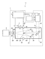
- FIG. 1 is a view schematically showing a configuration example of an exemplary LPP type EUV light generation system.
- FIG. 2 is a schematic view showing an example of a schematic configuration of a target generation device including the target supply unit shown in FIG.
- FIG. 3 is a cross-sectional view showing a schematic configuration example of the filter unit.
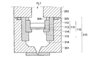
- FIG. 4 is a cross-sectional view showing a schematic configuration example of the filter unit according to the first embodiment.
- FIG. 5 is a cross-sectional view showing a schematic configuration example of a filter laminate according to a first modification of the first embodiment.
- FIG. 1 is a view schematically showing a configuration example of an exemplary LPP type EUV light generation system.
- FIG. 2 is a schematic view showing an example of a schematic configuration of a target generation device including the target supply unit shown in FIG.
- FIG. 3 is a cross-sectional view showing a schematic configuration example of the filter unit.
- FIG. 4 is a cross-sectional view showing a schematic configuration example of
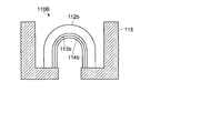
- FIG. 6 is a cross-sectional view showing a schematic configuration example of a filter laminate according to a second modified example of the first embodiment.
- FIG. 7 is a cross-sectional view showing a schematic configuration example of the filter unit according to the second embodiment.
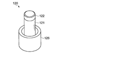
- FIG. 8 is a perspective view showing a schematic configuration example of the filter structure shown in FIG.
- FIG. 9 is a view showing a cross-sectional structure when the filter laminate in the filter structure shown in FIG. 8 is cut in a plane perpendicular to the extension direction of the internal space.
- FIG. 10 is a view showing a cross-sectional shape when the filter laminate according to the first modification of the second embodiment is cut in a plane perpendicular to the extending direction of the internal space.
- FIG. 11 is a view showing a cross-sectional shape when the filter laminate according to the second modification of the second embodiment is cut in a plane perpendicular to the extending direction of the internal space.
- FIG. 12 is a cross-sectional view showing a schematic configuration example of a filter unit according to the third embodiment.
- FIG. 13 is a view showing a cross-sectional structure when the filter laminate in the filter portion shown in FIG. 12 is sectioned in a plane perpendicular to the extending direction of the internal space.
- FIG. 14 is a cross-sectional view showing a schematic configuration example of the filter unit according to the fourth embodiment.
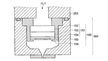
- FIG. 15 is a cross-sectional view showing a schematic configuration example of the filter unit according to the fifth embodiment.
- FIG. 16 is a cross-sectional view showing a schematic configuration example of the filter unit according to the sixth embodiment.
- FIG. 17 is a flowchart illustrating an example of a manufacturing process of manufacturing the filter structure according to the sixth embodiment by thermal spraying.
- FIG. 18 is a process cross-sectional view for explaining the process of the manufacturing process shown in FIG. 17 (1).
- FIG. 19 is a process cross-sectional view for illustrating the process of the manufacturing process shown in FIG. 17 (2).
- FIG. 20 is a process cross-sectional view for explaining the process of the manufacturing process shown in FIG. 17 (3).
- FIG. 21 is a process sectional view (4) for illustrating the process of the manufacturing process shown in FIG.
- FIG. 22 is a process sectional view (5) for illustrating the process of the manufacturing process shown in FIG.
- FIG. 23 is a process sectional view (6) for illustrating the process of the manufacturing process shown in FIG.
- SUMMARY Embodiments of the present disclosure relate to the supply of target material used to generate EUV light, and more particularly to a target generating apparatus that supplies target material into a chamber for EUV light generation. It may be.
- a target generating apparatus that supplies target material into a chamber for EUV light generation. It may be.
- the supply of the target material it is necessary to supply the target material accurately and stably to the region that generates the plasma that emits EUV light.
- the supply of the target material to the plasma generation region may be unstable. Therefore, in the following embodiments of the present disclosure, a target generation device capable of stably supplying a target material is illustrated.
- the present disclosure is not limited to these matters, and may relate to any matter related to the target material used to generate EUV light.
- FIG. 1 schematically illustrates the configuration of an exemplary LPP-type EUV light generation system.
- the EUV light generation device 1 may be used with at least one laser device 3.
- a system including the EUV light generation apparatus 1 and the laser apparatus 3 is referred to as an EUV light generation system 11.
- the EUV light generation system 1 may include a chamber 2 and a target supply unit 26. Chamber 2 may be sealable.
- the target supply unit 26 may be attached, for example, to penetrate the wall of the chamber 2.
- the material of the target material supplied from the target supply unit 26 may include, but is not limited to, tin, terbium, gadolinium, lithium, xenon, or a combination of any two or more thereof.
- the wall of the chamber 2 may be provided with at least one through hole.
- a window 21 may be provided in the through hole, and the pulse laser beam 32 output from the laser device 3 may be transmitted through the window 21.
- an EUV collector mirror 23 having a spheroidal reflecting surface may be disposed inside the chamber 2, for example.
- the EUV collector mirror 23 may have first and second focal points.
- a multilayer reflective film in which molybdenum and silicon are alternately stacked may be formed on the surface of the EUV collector mirror 23.
- the EUV collector mirror 23 is preferably arranged, for example, such that its first focal point is located at the plasma generation region 25 and its second focal point is located at the intermediate focusing point (IF) 292.
- a through hole 24 may be provided in the central portion of the EUV collector mirror 23, and the pulse laser beam 33 may pass through the through hole 24.
- the EUV light generation apparatus 1 may include an EUV light generation controller 5, a target sensor 4 and the like.
- the target sensor 4 may have an imaging function, and may be configured to detect the presence, trajectory, position, velocity and the like of the target 27.
- the EUV light generation apparatus 1 may include a connection part 29 that brings the inside of the chamber 2 into communication with the inside of the exposure apparatus 6. Inside the connection portion 29, a wall 291 having an aperture 293 may be provided. The wall 291 may be arranged such that its aperture 293 is located at the second focus position of the EUV collector mirror 23.
- the EUV light generation apparatus 1 may include a laser beam traveling direction control unit 34, a laser beam focusing mirror 22, a target recovery unit 28 for recovering the target 27, and the like.
- the laser light traveling direction control unit 34 may include an optical element for defining the traveling direction of the laser light, and an actuator for adjusting the position, attitude, and the like of the optical element.
- the pulsed laser beam 31 output from the laser device 3 passes through the laser beam traveling direction control unit 34, passes through the window 21 as the pulsed laser beam 32, and enters the chamber 2 May be
- the pulsed laser beam 32 may travel along the at least one laser beam path into the chamber 2, be reflected by the laser beam focusing mirror 22, and be irradiated to the at least one target 27 as the pulsed laser beam 33.
- the target supply unit 26 may be configured to output the target 27 toward the plasma generation region 25 inside the chamber 2.
- the target 27 may be irradiated with at least one pulse included in the pulsed laser light 33.
- the target 27 irradiated with the pulsed laser light may be plasmatized, and radiation 251 may be emitted from the plasma.
- the EUV light 252 included in the radiation 251 may be selectively reflected by the EUV collector mirror 23.
- the EUV light 252 reflected by the EUV collector mirror 23 may be collected at an intermediate collection point 292 and output to the exposure apparatus 6. Note that a plurality of pulses included in the pulsed laser light 33 may be irradiated to one target 27.
- the EUV light generation controller 5 may be configured to centrally control the entire EUV light generation system 11.
- the EUV light generation controller 5 may be configured to process image data or the like of the target 27 captured by the target sensor 4. Further, the EUV light generation controller 5 may be configured to control, for example, the timing at which the target 27 is output, the output direction of the target 27, and the like. Furthermore, the EUV light generation controller 5 may be configured to control, for example, the oscillation timing of the laser device 3, the traveling direction of the pulse laser beam 32, the focusing position of the pulse laser beam 33, and the like.
- the various controls described above are merely exemplary, and other controls may be added as needed.
- the terms used in the present disclosure are defined as follows.
- the "droplet” may be a droplet of melted target material.
- the shape may be approximately spherical.
- the “plasma generation region” may be a three-dimensional space preset as a space in which plasma is generated.
- the cross-section or cross-sectional view of each part in the target generation device refers to the cross-section of the plane including the trajectory of the droplet output from the nozzle hole, unless otherwise stated. Or it may be a sectional view.
- the “dense body” may be a crystalline body or a single crystal which is densified by aligning the orientation of particles constituting the ceramic.
- the “stacking direction” may be the direction in which the layers are stacked in the stack. "Upstream” and “downstream” of a flow path may correspond to “upstream” and “downstream” in the flow when fluid is flowed to the flow path.
- Target Generation Device Next, an example of a target generation device including the target supply unit 26 shown in FIG. 1 will be described in detail with reference to the drawings.
- FIG. 2 is a schematic diagram showing an example of a schematic configuration of a target generation device including the target supply unit 26 shown in FIG.
- the target generation device may include, in addition to the target supply unit 26, a pressure regulator 520, a temperature variable device 540, a control unit 51, and a piezo power supply 552.
- the target supply unit 26 may include a tank unit 260, a filter unit 300, a nozzle unit 266, and a piezo element 551.
- the tank portion 260 may include a tank 261 and a lid 262.
- the target material 271 may be stored in the tank unit 260.
- the target material 271 may be a metal target such as tin (Sn).
- a cylindrical convex portion 263 which protrudes into the chamber 2 (see FIG. 1) may be provided.
- the convex portion 263 may be integrally formed with the tank 261 or may be separately formed.
- the material of the tank 261, the convex portion 263, the lid 262, and the filter portion 300 may be a material having low reactivity with the target material 271.
- the material having low reactivity with the target material 271 may be, for example, molybdenum (Mo).
- a filter unit 300 for housing the filter laminate 100 may be provided on the bottom surface of the convex portion 263.
- a flow path may be formed in the convex portion 263 and the filter portion 300 so as to communicate from the tank 261 to the nozzle portion 266.
- the flow path may be open at the lower surface of the filter unit 300. The details of the filter unit 300 will be described later.
- the nozzle portion 266 may be provided to cover the opening on the lower surface of the filter portion 300.
- a nozzle hole 267 may be formed in the nozzle portion 266.
- the nozzle hole 267 may be in communication with the flow passage in the filter unit 300.
- the hole diameter of the nozzle hole 267 may be, for example, 2 to 6 ⁇ m.
- the material of the nozzle portion 266 may be molybdenum (Mo).
- the pressure regulator 520 may include a pressure control unit 525, an exhaust device 524, valves 521 and 522, and a pressure sensor 523.
- the exhaust device 524 may be connected to a cylinder 530 of inert gas via a gas pipe 531.
- the cylinder 530 may be provided with a valve 534 for adjusting the pressure of the supplied gas.
- Valves 521 and 522 may be provided at two locations on the gas pipe 531.
- a gas pipe 532 may be branched from the gas pipe 531 between the valves 521 and 522.
- the gas pipe 532 may communicate with the inside of the tank portion 260.
- the pressure sensor 523 may be provided for the gas pipe 532.
- the temperature variable device 540 may include a heater 541, a temperature sensor 542, a heater power supply 543, and a temperature control unit 544.
- the heater 541 may be provided to heat the target material 271 in the tank unit 260.
- the installation position of the heater 541 may be the side outer periphery of the tank 261.
- Temperature sensor 542 may be arranged to measure the temperature of target material 271 within tank portion 260 or tank portion 260.
- the installation position of the temperature sensor 542 may be the side surface of the tank 261.
- the heater power supply 543 may supply a current to the heater 541.
- the output signal line from the control unit 51 may be connected to the piezo power supply 552, the temperature control unit 544, the pressure control unit 525, and the EUV light generation controller 5.
- An input signal line to the control unit 51 may be connected to the temperature control unit 544, the pressure control unit 525, and the EUV light generation controller 5.
- the control unit 51 of the target generation device shown in FIG. 2 may execute the following process when the droplet output preparation signal is input from the control unit of the EUV light generation control device or the external device.
- control unit 51 may control the pressure regulator 520 so as to exhaust the gas in the tank unit 260 first.
- the pressure control unit 525 of the pressure regulator 520 may drive the exhaust device 524 with the valve 521 closed and the valve 522 opened.
- the control unit 51 may control the temperature variable device 540 so that the target material 271 in the tank unit 260 is melted.
- the temperature control unit 544 of the temperature variable device 540 may drive the heater 541 so that, for example, the detection value of the temperature sensor 542 becomes the predetermined temperature Top.
- the predetermined temperature Top may be a temperature equal to or higher than the melting point of tin (temperature 232 ° C.).
- the predetermined temperature Top may be a temperature range. The temperature range may be, for example, 240 ° C to 290 ° C.
- control unit 51 determines whether or not the detection value of the temperature sensor 542 maintains the predetermined temperature Top or more for a predetermined time, and if it is maintained, the control unit 51 of the EUV light generation controller 5 or the external device. The control unit may be notified that the droplet output preparation is completed.
- the control unit 51 instructs the pressure regulator 520 to set the pressure in the tank unit 260 to a predetermined pressure P (for example, 10 MPa (mega It may be instructed to boost up to the pascal)).
- a predetermined pressure P for example, 10 MPa (mega It may be instructed to boost up to the pascal)
- the pressure control unit 525 of the pressure regulator 520 stops the exhaust device 524 and opens the valve 521 in the state where the valve 522 is closed, whereby the inert gas from the cylinder 530 is stored in the tank unit 260. You may introduce it.
- the pressure control unit 525 adjusts the pressure in the tank unit 260 to the predetermined pressure P by adjusting the opening and closing of the valves 521 and 522 next. Control to maintain may be executed.
- the jet of the target material 271 may be output from the nozzle hole 267 while the pressure in the tank unit 260 is maintained at the predetermined pressure P.
- control unit 51 may control the piezo power supply 552 so that the jet of the target material 271 discharged from the nozzle hole 267 changes into droplets of a predetermined size and a predetermined cycle. As a result, desired droplets can be supplied to the plasma generation region 25 (see FIG. 1) in the chamber.
- FIG. 3 is a cross-sectional view showing a schematic configuration example of the filter unit.
- the filter unit 300 may include a flange 301, a filter laminate 100, a filter holder 314, and at least one shim 304.
- the material of the flange 301 and the filter holder 314 may be a material having low reactivity with the target material 271.
- the material having low reactivity with the target material 271 may be, for example, molybdenum (Mo).
- the material of the shim 304 may also be a material (for example, Mo) that has low reactivity with the target material 271.
- the flange 301 may have a cylindrical shape having the same diameter as the convex portion 263.
- the flange 301 may be fixed to the convex portion 263 of the tank portion 260 by a bolt not shown.
- the O-ring 304 may seal between the flange 301 and the protrusion 263.
- the O-ring 304 is not an essential component. That is, when a face seal is formed between the flange 301 and the protrusion 263, the O-ring 304 may be omitted.
- the space between the flange 301 and the projection 263 may be sealed by both the seal by the O-ring 304 and the face seal.
- a channel FL1 continuous with the channel FL1 in the convex portion 263 may be formed in the flange 301.
- an enlarged diameter portion for housing the filter laminate 100 may be formed in the flow path FL1 in the flange 301.
- the filter laminate 100 may be accommodated without rattling with the filter holder 314 and the at least one shim 304 in this enlarged diameter portion.
- the filter laminate 100 may be provided such that the lamination direction thereof substantially matches the extending direction of the flow path FL1 in the flange 301.
- the filter holder 314 and the shim 304 may have a cylindrical or ring shape.
- the contact surfaces of the flange 301 and the filter holder 314 may be both polished surfaces. Further, both surfaces of each shim 304, the contact portion between the projection 263 and the shim 304, and the contact portion between the filter holder 314 and the shim 304 may be polished surfaces. The contact at each polishing surface may form a face seal.
- the filter laminate 100 may filter out particles such as tin oxide contained in the target material 271.
- the filter laminate 100 may have a structure in which a plurality of filters are stacked. In the example shown in FIG. 3, a filter laminate 100 composed of three filters 101 to 103 is illustrated.
- the three filters 101 to 103 may have filter pore sizes of, for example, 20 ⁇ m (micrometers), 10 ⁇ m, and 6 ⁇ m in order from the tank portion 260 side.
- Each of the filters 101 to 103 may be a porous material such as a porous glass body having an aluminum oxide-silicon dioxide glass as a skeleton.
- a part of the filter may be broken and particles may be generated due to friction caused by thermal expansion and contraction during assembly, heating and cooling.
- particles generated from the filter 103 may not be removable by the filter laminate 100.
- Such particles can reach the nozzle holes 267 and cause clogging of the nozzle holes 267 and instability of the trajectory of the droplets 27. Therefore, in the following embodiments, a filter structure capable of suppressing the generation of particles caused by the filter laminate 100, a target generation device, and a method of manufacturing the filter structure will be illustrated.
- an intermediate member may be provided for mounting the filter laminate on the filter holder 314.
- this intermediate member is called a socket.
- FIG. 4 is a cross-sectional view showing a schematic configuration example of the filter unit according to the first embodiment. In the following description, configurations different from the configuration of the filter unit 300 shown in FIG. 3 will be described.
- the filter unit 310 may have a configuration similar to that of the filter unit 300 shown in FIG. 3 except that the filter laminate 100 is replaced with the filter structure 110. .
- Filter structure 110 may include filter stack 111 and socket 115.
- the filter laminate 111 may be a disk-shaped filter having a multilayer structure.
- This multilayer structure may be a structure formed by a lamination molding process. Further, the number of layers in the multilayer structure may be three. FIG. 3 shows the case of three layers 112-114.
- the layers 112 to 114 may be porous materials having different pore sizes.
- a porous material for example, alumina may be used.
- the hole diameter of each of the layers 112 to 114 may be larger as the layer located on the upstream side of the flow of the target material 271 (also referred to as the upstream side in the stacking direction, hereinafter the same).
- the pore diameter of the layer 112 located most upstream with respect to the flow of the target material 271 may be 12 ⁇ m, in which case the pore diameter of the layer 113 may be 0.8 ⁇ m.
- the hole diameter of the layer 114 located most downstream with respect to the flow of the target material 271 may be 0.2 ⁇ m.
- At least one of the layers 112-114 may be thicker than the other layers.
- layer 112 may be thicker than the other layers 113 and 114. In that case, layer 112 can act as a support for the other layers 113 and 114 as well as the entire filter stack 111.
- the layers 112 to 114 may be thicker as the layer located upstream with respect to the flow of the target material 271.
- the thickness of layer 112 may be 2 mm (millimeters), in which case the thickness of layer 113 may be 30 ⁇ m, and the thickness of layer 114 may be 20 ⁇ m.
- the socket 115 can hold the filter stack 111 and may have a shape that fits in the filter holder 314. At this time, the contact portion between the socket 115 and the filter holder 314 may extend around the side of the socket 115 in order to prevent the target material 271 from leaking.
- the socket 115 may be an annular member made of the same material as the filter laminate 111.
- the socket 115 may be a compact of alumina (alumina ceramic) or a sapphire single crystal.
- the porosity of each of the layers 112 to 114 constituting the filter laminate 111 may be, for example, 40 to 50%.
- the porosity of the socket 115 may be, for example, 2% or less.
- the contact portions of the socket 115 and the filter holder 314 may be polished. Thereby, a face seal may be formed between the socket 115 and the filter holder 314.
- the filter laminate 111 and the socket 115 may be integrated by bonding.
- these bonds may be thermal bonds or glass bonds.
- the filter holder 110 may be mounted with the filter structure 110 in a state where the filter laminate 111 and the socket 115 are joined.
- the socket 115 can be assembled to the filter holder 314.
- the socket 115 can be formed of, for example, a dense ceramic or a single crystal as described above. Therefore, it is possible to reduce the loss of the porous material constituting the filter laminate 111 due to friction at the time of assembly, heating and cooling. As a result, generation of particles generated at the time of assembly, heating and cooling can be suppressed, and thereby clogging of the nozzle holes 267 and instability of the droplet trajectory can be suppressed.
- FIGS. 5 and 6 show a modification of the filter laminate 111 shown in FIG. In the following description, configurations different from the configuration of the filter laminate 111 shown in FIG. 4 will be described.
- FIG. 5 is a cross-sectional view showing a schematic configuration example of a filter laminate according to a first modification.
- the filter laminate 110 ⁇ / b> A may be a multi-layered filter having a dome shape.
- the material (material), the hole diameter, the porosity, and the thickness of the layer 112 a located most upstream with respect to the flow of the target material 271 may be similar to that of the layer 112.
- the material, pore size, porosity and thickness of layers 113a and 114a may be similar to those of layers 113 and 114, respectively.
- FIG. 6 is a cross-sectional view showing a schematic configuration example of a filter laminate according to a second modified example.
- the filter laminate 110 ⁇ / b> B may be configured such that a cylindrical portion is extended with respect to the dome shape of the filter laminate 110 ⁇ / b> A shown in FIG. 5.
- the tubular portion may be spaced from the inner surface of the socket 115.
- the material, the pore size, the porosity and the thickness of the layers 112b to 114b may be the same as those of the layers 112 to 114, respectively.
- the filter laminate 111 may be deformed into various shapes, such as a polygonal pyramid shape, in addition to the above-described modifications.
- the filter area can be expanded by making the filter laminate 111 a dome-shaped or polygonal pyramid-shaped member. Thereby, the collection amount (or collection rate) of particles contained in the target material 271 can be improved. Also, the expansion of the filtration area can also increase the filter laminate replacement cycle.
- Embodiment 2 In the second embodiment, a hollow cylindrical filter laminate may be used.
- FIG. 7 is a cross-sectional view illustrating a schematic configuration example of the filter unit according to the second embodiment.
- FIG. 8 is a perspective view showing a schematic configuration example of the filter structure shown in FIG.
- FIG. 9 is a view showing a cross-sectional structure when the filter laminate in the filter structure shown in FIG. 8 is cut in a plane perpendicular to the extension direction of the internal space.
- the filter unit 320 may have a configuration similar to that of the filter unit 310 shown in FIG. 4 except that the filter structure 110 is replaced with the filter structure 120. .
- the filter structure 120 may include a filter stack 121, a cap 122 and a socket 126.
- the filter laminate 121 may be a hollow cylindrical filter having a multilayer structure.
- the material (material), the hole diameter, the porosity, and the thickness of the layer 123 located at the outermost periphery, which is the most upstream position with respect to the flow of the target material 271, may be similar to that of the layer 112.
- the material, pore size, porosity and thickness of layers 124 and 125 may be similar to layers 113 and 114, respectively.
- the opening at one end in the longitudinal direction of the hollow cylindrical filter laminate 121 may be sealed by a cap 122.
- the cap 122 may be a plate-like member made of the same material as that of the filter laminate 121.
- the cap 122 may be a compact of alumina (alumina ceramic) or a sapphire single crystal.
- the socket 126 may be provided at the other end of the filter laminate 121 in the longitudinal direction.
- the socket 126 can hold the filter laminate 121 and may have a shape that fits in the filter holder 314 without a gap.
- the material of the socket 126 may be the same as the socket 115 in the first embodiment.
- the contact portions of the socket 126 and the filter holder 314 may be polished. Thereby, a face seal may be formed between the socket 126 and the filter holder 314.
- the filter laminate 121 and the cap 122, and the filter laminate 121 and the socket 126 may be respectively integrated by bonding.
- the respective junctions may be similar to the junctions of the filter laminate 111 and the socket 115 exemplified in the first embodiment.
- the filter structure 120 having the above configuration may be assembled to the filter holder 314 such that the cap 122 side protrudes to the flow path FL1 on the tank portion 260 side.
- the filter structure 110 in a state in which the filter laminate 111 and the socket 115 are joined can be attached to the filter holder 314, the filter structure 110 occurs during assembly, heating and cooling. It is possible to suppress the generation of particles. As a result, clogging of the nozzle holes 267 and instability of the droplet trajectory can be suppressed.
- the shape of the filter laminate 121 according to the second embodiment is not limited to the hollow cylindrical shape. Below, the modification is shown.
- FIG. 10 is a view showing a cross-sectional shape when the filter laminate according to the first modified example is cut in a plane perpendicular to the extension direction of the internal space It is.
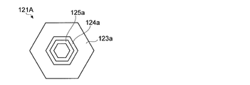
- the filter laminate 121A may have a regular hexagonal cross-sectional shape including the flow path of the target material 271 at the center.
- the shape is not limited to a regular hexagon, and may be various polygonal shapes.
- the outer contour of the outermost layer 123a and the outer contour of the inner layers 124a and 125a do not have to have a similar relationship. That is, the cross-sectional shape may be different for each of the layers 123 to 125.
- the material, the pore size, the porosity and the thickness of the layers 123a to 125a may be the same as those of the layers 112 to 114, respectively.
- FIG. 11 is a view showing a cross-sectional shape when the filter laminate according to the second modified example is cut in a plane perpendicular to the extending direction of the internal space.
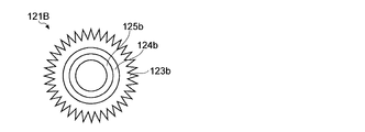
- the filter laminate 121B may have a sawtooth shape in which the outer contour of the outermost layer 123b repeats unevenness.
- a flow path of the target material 271 may be provided.
- the outer contour shape of the outermost layer 123a and the outer contour shape of the inner circumferential layers 124a and 125a need not have a similar relationship.
- the material (material), the pore size, the porosity and the thickness of the layers 123b to 125b may be the same as those of the layers 112 to 114, respectively.
- the cross-sectional shape of a filter laminated body may be suitably changed with the manufacturing method.
- the polygonal filter laminate 121A as illustrated in FIG. 10 can also be manufactured by combining a plurality of plate-like members.
- the shape of the cap sealing the opening at one end of the filter laminate may be appropriately changed in accordance with the cross-sectional shape of the filter laminate.
- the hollow cylindrical filter laminate may protrude not to the tank portion 260 but to the nozzle portion 266 side.
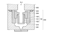
- FIG. 12 is a cross-sectional view showing a schematic configuration example of the filter unit according to the third embodiment.
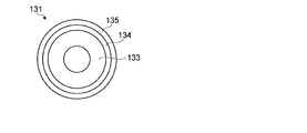
- FIG. 13 is a view showing a cross-sectional structure when the filter laminate in the filter portion shown in FIG. 12 is sectioned in a plane perpendicular to the extending direction of the internal space.
- the filter unit 330 may have a configuration similar to that of the filter unit 310 shown in FIG. 7 except that the filter structure 120 is replaced with the filter structure 130.
- the filter structure 130 may be configured such that the filter structure 120 is vertically inverted in portions other than the filter laminate 131.
- the filter laminate 131 may be a hollow cylindrical filter having a multilayer structure, like the filter laminate 121.
- the layer 133 located at the innermost periphery among the layers 133 to 135 constituting the filter laminate 131 is located at the uppermost stream,
- the layer 135 located at the outermost periphery may be located at the most downstream.
- the material, the pore size, the porosity and the thickness of each of the layers 133 to 135 may be the same as those of the layers 112 to 114, respectively.
- Embodiment 4 In the embodiments described above, the filter holder and the socket may be integrated. In the following description, a configuration different from this configuration will be described based on the filter unit 320 shown in FIG. However, the integration of the filter holder and the socket illustrated in the fourth embodiment may be applicable to the other embodiments.
- FIG. 14 is a cross-sectional view showing a schematic configuration example of the filter unit according to the fourth embodiment. As shown in FIG. 14, in the filter unit 340 according to the fourth embodiment, the filter holder 314 and the socket 126 shown in FIG. 7 are replaced with an integrated socket 144.
- the socket 144 can hold the filter laminate 121 and may have a shape that fits within the flange 301. At this time, the contact portion between the socket 144 and the flange 301 may extend around the side of the socket 144 in order to prevent the target material 271 from leaking.
- the socket 144 may be an annular member made of the same material as that of the filter laminate 121.
- the socket 144 may be a compact of alumina (alumina ceramic) or a sapphire single crystal.
- the contact portions of the socket 144 and the flange 301 may be polished, respectively. Thereby, a face seal may be formed between the socket 144 and the flange 301.
- the filter laminate 121 and the socket 144 may be integrated by bonding.
- these connections may be thermal bonding or glass bonding.
- the filter laminate 121 and the socket 144 are joined with an alumina adhesive, the two may be joined by firing.
- the socket 144 may be formed with a groove for receiving the shim 304.
- the contact surfaces of the flange 301 and the socket 144 may be respectively polished surfaces.
- the contact portions between the socket 144 and the shim 304 may be respectively polished surfaces.
- the contact at each polishing surface may form a face seal.
- the shim 304 may be omitted.
- the socket may be formed by thermal spraying.
- the following description is based on a configuration in which the filter holder 314 and the socket 115 are integrated in the filter unit 310 shown in FIG. 4, and in this configuration, the socket is formed by thermal spraying.
- the formation by thermal spraying of the socket illustrated in the fifth embodiment may be applicable to the other embodiments.
- FIG. 15 is a cross-sectional view showing a schematic configuration example of the filter unit according to the fifth embodiment.
- the filter unit 350 according to the fifth embodiment has a configuration similar to that of the filter unit 310 shown in FIG. 4 except that the filter structure 110 and the filter holder 314 are replaced by the filter structure 150. You may
- the filter holder 314 and the socket 115 may be replaced by an integrated socket 156.
- the filter laminate 111 may be replaced with the filter laminate 151.
- the filter laminate 151 may have a structure in which the first filter 152 to the third filter 154, which are different disk-shaped members, are overlapped.
- the shape, material (material), pore size, porosity and thickness of each of the filters 152 to 154 may be the same as those of the layers 112 to 114, respectively.
- another filter laminate such as the filter laminate 100 may be used instead of the filter laminate 151.
- the socket 156 may be a member formed by thermal spraying on the filter laminate 151. By forming the socket 156 by thermal spraying, it is possible to manufacture the filter structure 150 while holding the plurality of filters 152 to 154 integrally. In addition, the manufacturing process of the filter structure 150 by thermal spraying is mentioned later.
- the socket 156 can hold the filter laminate 151 and may have a shape that fits within the flange 301. At this time, the contact portion between the socket 156 and the flange 301 may extend around the side of the socket 156 in order to prevent the target material 271 from leaking.
- the material of the socket 156 may be a material (for example, Mo) that has low reactivity with the target material 271, as with the flange 301.
- the contact portions of the socket 156 and the flange 301 may be respectively polished. Thereby, a face seal may be formed between the socket 156 and the flange 301.
- the contact portions between the socket 156 and the convex portion 263 may also be polished. Thereby, a face seal may be formed between the socket 156 and the projection 263. In that case, the shim 304 between the socket 156 and the projection 263 can be omitted.
- the material (material) of the filter laminate 151 is selected when selecting the material (material) of the socket 156 It is not necessary to consider. Therefore, as the material (material) of the socket 156, the same material as the material (material) of the flange 301 can be selected.
- the material (material) of the socket 156 and the material (material) of the flange 301 the same, it is possible to reduce the stress caused by the thermal expansion difference at the time of assembly, heating and cooling. As a result, generation of particles generated at the time of assembly, heating and cooling can be suppressed, and thereby clogging of the nozzle holes 267 and instability of the droplet trajectory can be suppressed.
- the filter stack may include a support plate to increase stiffness.
- a configuration different from this configuration will be described based on the filter unit 350 shown in FIG.
- the support plate illustrated in the sixth embodiment may be applicable to other embodiments.
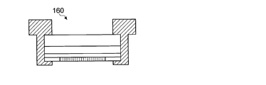
- FIG. 16 is a cross-sectional view showing a schematic configuration example of the filter unit according to the sixth embodiment.
- the socket 156 may further hold the support plate 165 in the filter unit 350 shown in FIG. 15.
- the support plate 165 may be, for example, a disk-shaped plate member having the same diameter as the first filter 152 to the third filter 154.
- the material of the support plate 165 may be a material having a low reactivity with the target material 271 (for example, Mo), or may be glass or the like.
- a plurality of through holes may be formed at the center of the support plate 165.
- the number of through holes may be, for example, 10 to 100.
- the hole diameter of each through hole may be, for example, about 100 to 1500 ⁇ m.
- Support of the filter laminate 151 by the support plate 165 makes it possible to increase the rigidity of the filter structure 160. Thereby, even when a relatively high pressure is applied to the target material 271 in the tank unit 260, for example, it is possible to suppress the breakage of the filter laminate 151.
- alumina or alumina ceramic
- sapphire single crystal is exemplified as a material of the filter laminate, the socket and the cap.
- other materials are exemplified.
- Socket Cap Material The material of the socket and cap is desirably a material that satisfies the following conditions 1 and 2. (1) Low reactivity with melted target material 271 (for example, tin) (2) Difference in thermal expansion coefficient with flange 301 is small
- the metal material used as the material of the flange 301 may be molybdenum (Mo) which has low reactivity with the target material (for example, tin). Therefore, as the material of the socket, a material having a small difference in thermal expansion coefficient with that of molybdenum may be selected, for example, from the above Table 1. Note that the fact that the difference in thermal expansion coefficient with molybdenum is small may be, for example, within ⁇ 20% of the thermal expansion coefficient of molybdenum. As such materials, silicon carbide, tungsten carbide, aluminum nitride, zirconium boride and boron carbide are listed in Table 1 above.
- the material of the filter laminate may be the same material that differs in structure from the material used for the socket, but may be different.
- the material of the filter laminate is desirably a material satisfying the following conditions 3 and 4 in addition to the conditions 1 and 2 for the socket and cap materials described above. (3) A material capable of forming a porous structure (4) A material capable of bonding with the material used for the socket or cap
- materials satisfying the above conditions 1 to 4 may be selected from Table 1, or other materials satisfying the conditions 1 to 4 and having similar properties may be selected.
- FIG. 17 is a flowchart showing an example of a manufacturing process of the filter structure by thermal spraying.
- 18 to 23 are cross-sectional views of the filter structure 160 in the main process for illustrating the process of the manufacturing process shown in FIG.
- the support plate 165 having the masking material 1006, the third filter 154, the second filter 153, and the first filter 152 having the masking material 1003 are bonded with an adhesive. Bonding may be performed (step S101).
- the third jig 1007 may be used as a support.
- a cyanoacrylate adhesive may be used as the adhesive.
- another adhesive may be used as long as it is an adhesive that can be removed by a solvent or the like.
- a filter assembly 161 in which the support plate 165 is adhered to the filter laminate 151 including the first filter 152 to the third filter 154 may be created.
- the filter assembly 161 may include masking materials 1003 and 1006.
- the socket material may be sprayed on the entire outside of the filter assembly 161 to form a thermal spray portion 1008 (step S102).
- the socket material may be molybdenum.
- the thickness of the thermally sprayed socket material may be, for example, about 500 ⁇ m at the thickest portion.
- the outer periphery of the thermal spraying part 1008 may be mechanically processed (step S103).
- the outer diameter of the thermal spray part 1009 after processing may be the same as the outer diameter of the same member in the completed filter structure 160.
- a ring member 1010 for locking the filter structure 160 to the flange 301 may be welded to the thermal spray portion 1009 (step S104).
- the outer shape of the holding portion 1009 may be mechanically processed (step S105). Thereby, the masking materials 1003 and 1006 in the filter assembly 161 may be exposed, respectively.
- step S106 the portion to be in contact with the flange 301 and the projection 263 in the welded ring member 1010 may be polished.
- the exposed masking materials 1003 and 1006 may be removed by a solvent (step S107). Thereby, the structure of the filter structure 160 may be obtained.
- the adhesive may be removed by a solvent (step S108).
- the filter structure 160 may be washed with pure water or the like (step S109), and particles remaining in the washed filter structure 160 may be measured (step S110).
- the cleaning of the filter structure 160 may be repeatedly performed (Step S111; NO) until the measured amount of particles falls within a predetermined allowable range (Step S111; YES).
- 26 target supply unit, 27: droplet, 110, 110A, 110B, 120, 130, 150, 160: filter structure, 111, 121, 121A, 121B, 131, 151: filter laminate, 112, 112a, 112b , 113, 113a, 113b, 114, 114a, 114b, 123, 123a, 123b, 124, 124a, 124b, 125, 125a, 125b, 133, 134, 135 ... layers, 115, 126, 144, 154 ... sockets, 122 ... Cap, 152, 153, 154 ... Filter, 165 ... Support plate, 260 ... Tank section, 261 ... Tank, 262 ...
- Lid Lid, 263 ... Convex section, 266 ... Nozzle section, 267 ... Nozzle hole, 271 ... Target material, 301 ... flange, 304 ... shim, 310, 3 0,330,340,350,360 ... filter unit, 314 ... filter holder
Landscapes
- Chemical & Material Sciences (AREA)
- Chemical Kinetics & Catalysis (AREA)
- Life Sciences & Earth Sciences (AREA)
- Geology (AREA)
- Physics & Mathematics (AREA)
- Engineering & Computer Science (AREA)
- Optics & Photonics (AREA)
- Plasma & Fusion (AREA)
- Exposure And Positioning Against Photoresist Photosensitive Materials (AREA)
- X-Ray Techniques (AREA)
- Filtering Materials (AREA)
- Filtration Of Liquid (AREA)
Abstract
本開示の一態様によるターゲット生成装置(26)は、フィルタ構造体(110,110A,110B,120,130,150,160)と、前記フィルタ構造体を収容し、内部に前記フィルタ構造体を通過する流路が存在するフランジ(301)と、内部に前記フランジ内の前記流路と連通し且つ所定のターゲット材料が貯留される空間が存在するタンク部(260)と、前記フランジに設けられ、前記フランジ内の前記流路を介して前記タンク部内の前記空間と連通するノズル部(266)と、を備えてもよい。本開示の一態様によるフィルタ構造体は、ポーラス材からなるフィルタ(111,121,121A,121B,131,151)と、前記フィルタと一体化されたソケット(115,126,144,154)と、を備えてもよい。
Description
本開示は、フィルタ構造体、ターゲット生成装置およびフィルタ構造体の製造方法に関する。
近年、半導体プロセスの微細化に伴って、半導体プロセスの光リソグラフィにおける転写パターンの微細化が急速に進展している。次世代においては、60nm~45nmの微細加工、さらには32nm以下の微細加工が要求されるようになる。このため、例えば32nm以下の微細加工の要求に応えるべく、波長13nm程度の極端紫外(EUV)光を生成するための装置と縮小投影反射光学系とを組み合わせた露光装置の開発が期待されている。
EUV光生成装置としては、ターゲット物質にレーザ光を照射することによって生成されるプラズマを用いられるLPP(Laser Produced Plasma)式の装置と、放電によって生成されるプラズマを用いられるDPP(Discharge Produced Plasma)式の装置と、軌道放射光を用いられるSR(Synchrotron Radiation)式の装置との3種類の装置が提案されている。
本開示の一態様によるフィルタ構造体(110,110A,110B,120,130,150,160)は、ポーラス材からなるフィルタ(111,121,121A,121B,131,151)と、前記フィルタと一体化されたソケット(115,126,144,156)と、を備えてもよい。
本開示の他の態様によるターゲット生成装置(26)は、上述のフィルタ構造体と、前記フィルタ構造体を収容し、内部に前記フィルタ構造体を通過する流路が存在するフランジ(301)と、内部に前記フランジ内の前記流路と連通し且つ所定のターゲット材料が貯留される空間が存在するタンク部(260)と、前記フランジに設けられ、前記フランジ内の前記流路を介して前記タンク部内の前記空間と連通するノズル部(266)と、を備えてもよい。
本開示のさらに他の態様によるフィルタ構造体の製造方法は、ポーラス材からなるフィルタを備えたフィルタ構造体の製造方法であって、一部にマスキング材が形成された前記フィルタを重ねて配置する工程と、前記マスキング材が形成された前記フィルタの周囲に前記フィルタと熱膨張係数が略等しい材料(1008)を溶射する工程と、前記材料を加工して前記マスキング材の一部を露出させる工程と、前記マスキング材を除去する工程と、を含んでもよい。
本開示のいくつかの実施形態を、単なる例として、添付の図面を参照して以下に説明する。
図1は、例示的なLPP式のEUV光生成システムの構成例を概略的に示す図である。
図2は、図1に示すターゲット供給部を含むターゲット生成装置の概略構成例を示す模式図である。
図3は、フィルタ部の概略構成例を示す断面図である。
図4は、実施形態1にかかるフィルタ部の概略構成例を示す断面図である。
図5は、実施形態1の第1変形例にかかるフィルタ積層体の概略構成例を示す断面図である。
図6は、実施形態1の第2変形例にかかるフィルタ積層体の概略構成例を示す断面図である。
図7は、実施形態2にかかるフィルタ部の概略構成例を示す断面図である。
図8は、図7に示すフィルタ構造体の概略構成例を示す斜視図である。
図9は、図8に示すフィルタ構造体におけるフィルタ積層体を内部空間の延在方向に対して垂直な面で輪切りにした際の断面構造を示す図である。
図10は、実施形態2の第1変形例にかかるフィルタ積層体を内部空間の延在方向に対して垂直な面で輪切りにした際の断面形状を示す図である。
図11は、実施形態2の第2変形例にかかるフィルタ積層体を内部空間の延在方向に対して垂直な面で輪切りにした際の断面形状を示す図である。
図12は、実施形態3にかかるフィルタ部の概略構成例を示す断面図である。
図13は、図12に示すフィルタ部におけるフィルタ積層体を内部空間の延在方向に対して垂直な面で輪切りにした際の断面構造を示す図である。
図14は、実施形態4にかかるフィルタ部の概略構成例を示す断面図である。
図15は、実施形態5にかかるフィルタ部の概略構成例を示す断面図である。
図16は、実施形態6にかかるフィルタ部の概略構成例を示す断面図である。
図17は、実施形態6にかかるフィルタ構造体を溶射によって製造する製造工程の一例を示すフローチャートである。
図18は、図17に示す製造工程の過程を説明するためのプロセス断面図である(1)。
図19は、図17に示す製造工程の過程を説明するためのプロセス断面図である(2)。
図20は、図17に示す製造工程の過程を説明するためのプロセス断面図である(3)。
図21は、図17に示す製造工程の過程を説明するためのプロセス断面図である(4)。
図22は、図17に示す製造工程の過程を説明するためのプロセス断面図である(5)。
図23は、図17に示す製造工程の過程を説明するためのプロセス断面図である(6)。
内容
1.概要
2.極端紫外光生成装置の全体説明
2.1 構成
2.2 動作
3.用語の説明
3.1 上記2.の用語説明
3.2 開示毎の独自用語説明
4.ターゲット生成装置
4.1 構成
4.2 動作
5.フィルタ部
5.1 構成
5.2 動作
5.3 課題
6.実施形態1
6.1 構成
6.2 作用
7.実施形態1の変形例
7.1 構成
7.1.1 第1変形例
7.1.2 第2変形例
7.1.3 その他の変形例
7.2 作用
8.実施形態2
8.1 構成
8.2 作用
9.実施形態2の変形例
9.1 構成
9.1.1 第1変形例
9.1.2 第2変形例
9.2 作用
10.実施形態3
10.1 構成
10.2 作用
11.実施形態4
11.1 構成
11.2 作用
12.実施形態5
12.1 構成
12.2 作用
13.実施形態6
13.1 構成
13.2 作用
14.構成材料
14.1 ソケット・キャップ材料
14.2 フィルタ材料
15.溶射によるフィルタ構造体の製造工程
1.概要
2.極端紫外光生成装置の全体説明
2.1 構成
2.2 動作
3.用語の説明
3.1 上記2.の用語説明
3.2 開示毎の独自用語説明
4.ターゲット生成装置
4.1 構成
4.2 動作
5.フィルタ部
5.1 構成
5.2 動作
5.3 課題
6.実施形態1
6.1 構成
6.2 作用
7.実施形態1の変形例
7.1 構成
7.1.1 第1変形例
7.1.2 第2変形例
7.1.3 その他の変形例
7.2 作用
8.実施形態2
8.1 構成
8.2 作用
9.実施形態2の変形例
9.1 構成
9.1.1 第1変形例
9.1.2 第2変形例
9.2 作用
10.実施形態3
10.1 構成
10.2 作用
11.実施形態4
11.1 構成
11.2 作用
12.実施形態5
12.1 構成
12.2 作用
13.実施形態6
13.1 構成
13.2 作用
14.構成材料
14.1 ソケット・キャップ材料
14.2 フィルタ材料
15.溶射によるフィルタ構造体の製造工程
以下、本開示の実施形態について、図面を参照しながら詳しく説明する。以下に説明される実施形態は、本開示のいくつかの例を示すものであって、本開示の内容を限定するものではない。また、各実施形態で説明される構成及び動作の全てが本開示の構成及び動作として必須であるとは限らない。なお、同一の構成要素には同一の参照符号を付して、重複する説明を省略する。
1.概要
本開示の実施形態は、EUV光の生成に用いられるターゲット材料の供給に関係するものであって、具体的には、ターゲット材料をEUV光生成用のチャンバ内に供給するターゲット生成装置に関するものであってよい。ターゲット材料の供給では、EUV光を放射するプラズマを生成する領域に正確且つ安定してターゲット材料を供給する必要がある。しかしながら、ターゲット材料に内在するパーティクル等が原因で、プラズマ生成領域へのターゲット材料の供給が不安定になることがある。そこで本開示の以下の実施形態では、ターゲット材料を安定して供給することが可能なターゲット生成装置を例示する。ただし、本開示はこれらの事項に限定されず、EUV光の生成に用いられるターゲット材料に関係するあらゆる事項に関連するものであってよい。
本開示の実施形態は、EUV光の生成に用いられるターゲット材料の供給に関係するものであって、具体的には、ターゲット材料をEUV光生成用のチャンバ内に供給するターゲット生成装置に関するものであってよい。ターゲット材料の供給では、EUV光を放射するプラズマを生成する領域に正確且つ安定してターゲット材料を供給する必要がある。しかしながら、ターゲット材料に内在するパーティクル等が原因で、プラズマ生成領域へのターゲット材料の供給が不安定になることがある。そこで本開示の以下の実施形態では、ターゲット材料を安定して供給することが可能なターゲット生成装置を例示する。ただし、本開示はこれらの事項に限定されず、EUV光の生成に用いられるターゲット材料に関係するあらゆる事項に関連するものであってよい。
2.EUV光生成システムの全体説明
2.1 構成
図1に、例示的なLPP式のEUV光生成システムの構成を概略的に示す。EUV光生成装置1は、少なくとも1つのレーザ装置3と共に用いられてもよい。本願においては、EUV光生成装置1及びレーザ装置3を含むシステムを、EUV光生成システム11と称する。図1に示し、かつ、以下に詳細に説明するように、EUV光生成装置1は、チャンバ2、ターゲット供給部26を含んでもよい。チャンバ2は、密閉可能であってもよい。ターゲット供給部26は、例えば、チャンバ2の壁を貫通するように取り付けられてもよい。ターゲット供給部26から供給されるターゲット物質の材料は、スズ、テルビウム、ガドリニウム、リチウム、キセノン、又は、それらの内のいずれか2つ以上の組合せを含んでもよいが、これらに限定されない。
2.1 構成
図1に、例示的なLPP式のEUV光生成システムの構成を概略的に示す。EUV光生成装置1は、少なくとも1つのレーザ装置3と共に用いられてもよい。本願においては、EUV光生成装置1及びレーザ装置3を含むシステムを、EUV光生成システム11と称する。図1に示し、かつ、以下に詳細に説明するように、EUV光生成装置1は、チャンバ2、ターゲット供給部26を含んでもよい。チャンバ2は、密閉可能であってもよい。ターゲット供給部26は、例えば、チャンバ2の壁を貫通するように取り付けられてもよい。ターゲット供給部26から供給されるターゲット物質の材料は、スズ、テルビウム、ガドリニウム、リチウム、キセノン、又は、それらの内のいずれか2つ以上の組合せを含んでもよいが、これらに限定されない。
チャンバ2の壁には、少なくとも1つの貫通孔が設けられていてもよい。その貫通孔には、ウインドウ21が設けられてもよく、ウインドウ21をレーザ装置3から出力されるパルスレーザ光32が透過してもよい。チャンバ2の内部には、例えば、回転楕円面形状の反射面を有するEUV集光ミラー23が配置されてもよい。EUV集光ミラー23は、第1及び第2の焦点を有し得る。EUV集光ミラー23の表面には、例えば、モリブデンとシリコンとが交互に積層された多層反射膜が形成されていてもよい。EUV集光ミラー23は、例えば、その第1の焦点がプラズマ生成領域25に位置し、その第2の焦点が中間集光点(IF)292に位置するように配置されるのが好ましい。EUV集光ミラー23の中央部には貫通孔24が設けられていてもよく、貫通孔24をパルスレーザ光33が通過してもよい。
EUV光生成装置1は、EUV光生成制御装置5、ターゲットセンサ4等を含んでもよい。ターゲットセンサ4は、撮像機能を有してもよく、ターゲット27の存在、軌跡、位置、速度等を検出するよう構成されてもよい。
また、EUV光生成装置1は、チャンバ2の内部と露光装置6の内部とを連通させる接続部29を含んでもよい。接続部29内部には、アパーチャ293が形成された壁291が設けられてもよい。壁291は、そのアパーチャ293がEUV集光ミラー23の第2の焦点位置に位置するように配置されてもよい。
さらに、EUV光生成装置1は、レーザ光進行方向制御部34、レーザ光集光ミラー22、ターゲット27を回収するためのターゲット回収部28等を含んでもよい。レーザ光進行方向制御部34は、レーザ光の進行方向を規定するための光学素子と、この光学素子の位置、姿勢等を調整するためのアクチュエータとを備えてもよい。
2.2 動作
図1を参照に、レーザ装置3から出力されたパルスレーザ光31は、レーザ光進行方向制御部34を経て、パルスレーザ光32としてウインドウ21を透過してチャンバ2内に入射してもよい。パルスレーザ光32は、少なくとも1つのレーザ光経路に沿ってチャンバ2内に進み、レーザ光集光ミラー22で反射されて、パルスレーザ光33として少なくとも1つのターゲット27に照射されてもよい。
図1を参照に、レーザ装置3から出力されたパルスレーザ光31は、レーザ光進行方向制御部34を経て、パルスレーザ光32としてウインドウ21を透過してチャンバ2内に入射してもよい。パルスレーザ光32は、少なくとも1つのレーザ光経路に沿ってチャンバ2内に進み、レーザ光集光ミラー22で反射されて、パルスレーザ光33として少なくとも1つのターゲット27に照射されてもよい。
ターゲット供給部26は、ターゲット27をチャンバ2内部のプラズマ生成領域25に向けて出力するよう構成されてもよい。ターゲット27には、パルスレーザ光33に含まれる少なくとも1つのパルスが照射されてもよい。パルスレーザ光が照射されたターゲット27はプラズマ化し、そのプラズマから放射光251が放射され得る。放射光251に含まれるEUV光252は、EUV集光ミラー23によって選択的に反射されてもよい。EUV集光ミラー23によって反射されたEUV光252は、中間集光点292で集光され、露光装置6に出力されてもよい。なお、1つのターゲット27に、パルスレーザ光33に含まれる複数のパルスが照射されてもよい。
EUV光生成制御装置5は、EUV光生成システム11全体の制御を統括するよう構成されてもよい。EUV光生成制御装置5は、ターゲットセンサ4によって撮像されたターゲット27のイメージデータ等を処理するよう構成されてもよい。また、EUV光生成制御装置5は、例えば、ターゲット27が出力されるタイミング、ターゲット27の出力方向等を制御するよう構成されてもよい。さらに、EUV光生成制御装置5は、例えば、レーザ装置3の発振タイミング、パルスレーザ光32の進行方向、パルスレーザ光33の集光位置等を制御するよう構成されてもよい。上述の様々な制御は単なる例示に過ぎず、必要に応じて他の制御が追加されてもよい。
3.用語の説明
3.1 上記2.の用語説明
本開示において使用される用語について、以下のように定義する。
「ドロップレット」とは、融解したターゲット材料の液滴であってもよい。その形状は、略球形であってもよい。
「プラズマ生成領域」とは、プラズマが生成される空間として予め設定された3次元空間であってもよい。
3.1 上記2.の用語説明
本開示において使用される用語について、以下のように定義する。
「ドロップレット」とは、融解したターゲット材料の液滴であってもよい。その形状は、略球形であってもよい。
「プラズマ生成領域」とは、プラズマが生成される空間として予め設定された3次元空間であってもよい。
3.2 開示毎の独自用語説明
以下の説明において、ターゲット生成装置における各部の断面または断面図とは、補足の説明がない限り、そのノズル孔から出力されるドロップレットの軌道を含む面の断面または断面図であってよい。
「緻密体」とは、セラミックスを構成する粒子の方位を揃えることで緻密化された結晶体あるいは単結晶であってもよい。
「積層方向」とは、積層体において層が積み重なっている方向であってよい。
流路の「上流」および「下流」とは、その流路に対して流体を流した場合にその流れにおける「上流」および「下流」に相当してよい。
以下の説明において、ターゲット生成装置における各部の断面または断面図とは、補足の説明がない限り、そのノズル孔から出力されるドロップレットの軌道を含む面の断面または断面図であってよい。
「緻密体」とは、セラミックスを構成する粒子の方位を揃えることで緻密化された結晶体あるいは単結晶であってもよい。
「積層方向」とは、積層体において層が積み重なっている方向であってよい。
流路の「上流」および「下流」とは、その流路に対して流体を流した場合にその流れにおける「上流」および「下流」に相当してよい。
4.ターゲット生成装置
つづいて、図1に示すターゲット供給部26を含むターゲット生成装置の一例を、図面を参照して詳細に説明する。
つづいて、図1に示すターゲット供給部26を含むターゲット生成装置の一例を、図面を参照して詳細に説明する。
4.1 構成
図2は、図1に示すターゲット供給部26を含むターゲット生成装置の概略構成例を示す模式図である。図2に示すように、ターゲット生成装置は、ターゲット供給部26の他に、圧力調節器520と、温度可変装置540と、制御部51と、ピエゾ電源552とを含んでいてもよい。
図2は、図1に示すターゲット供給部26を含むターゲット生成装置の概略構成例を示す模式図である。図2に示すように、ターゲット生成装置は、ターゲット供給部26の他に、圧力調節器520と、温度可変装置540と、制御部51と、ピエゾ電源552とを含んでいてもよい。
ターゲット供給部26は、タンク部260と、フィルタ部300と、ノズル部266と、ピエゾ素子551とを含んでいてもよい。
タンク部260は、タンク261と、蓋262とを含んでもよい。タンク部260内には、ターゲット材料271が貯蔵されてもよい。ターゲット材料271は、錫(Sn)などの金属ターゲットであってもよい。タンク261の下部には、チャンバ2(図1参照)内へ突出する円筒状の凸部263が設けられていてもよい。この凸部263は、タンク261と一体形成されてもよいし、別体であってもよい。
タンク261および凸部263と蓋262とフィルタ部300との材料は、ターゲット材料271との反応性が低い材料であってもよい。ターゲット材料271との反応性が低い材料は、たとえばモリブデン(Mo)であってもよい。
凸部263の底面には、フィルタ積層体100を収容するフィルタ部300が設けられてもよい。凸部263およびフィルタ部300の内部には、タンク261からノズル部266まで連通する流路が形成されてもよい。この流路は、フィルタ部300の下面において開口していてもよい。フィルタ部300の詳細については、後述において触れる。
ノズル部266は、フィルタ部300下面の開口を覆うように設けられてもよい。ノズル部266には、ノズル孔267が形成されていてもよい。ノズル孔267は、フィルタ部300内の流路と連通していてもよい。ノズル孔267の孔径は、たとえば2~6μmであってもよい。ノズル部266の材料は、モリブデン(Mo)であってもよい。
圧力調節器520は、圧力制御部525と、排気装置524と、バルブ521および522と、圧力センサ523とを含んでもよい。排気装置524は、ガス配管531を介して不活性ガスのボンベ530に接続されてもよい。ボンベ530には、供給するガスの圧力を調節するバルブ534が設けられていてもよい。
ガス配管531上の2箇所には、バルブ521および522が設けられてもよい。バルブ521および522間のガス配管531からは、ガス配管532が分岐していてもよい。ガス配管532は、タンク部260内に連通していてもよい。圧力センサ523は、ガス配管532に対して設けられてもよい。
温度可変装置540は、ヒータ541と、温度センサ542と、ヒータ電源543と、温度制御部544とを含んでもよい。
ヒータ541は、タンク部260内のターゲット材料271を加熱するように設けられてもよい。ヒータ541の設置位置は、タンク261の側面外周であってもよい。温度センサ542は、タンク部260またはタンク部260内のターゲット材料271の温度を計測するように配置されてもよい。温度センサ542の設置位置は、タンク261の側面であってもよい。ヒータ電源543は、ヒータ541に電流を供給してもよい。
制御部51からの出力信号線は、ピエゾ電源552と、温度制御部544と、圧力制御部525と、EUV光生成制御装置5とに接続されてもよい。制御部51への入力信号線は、温度制御部544と、圧力制御部525と、EUV光生成制御装置5とに接続されてもよい。
4.2 動作
図2に示すターゲット生成装置の制御部51は、EUV光生成制御装置または外部装置の制御部からドロップレット出力準備信号が入ると以下の処理を実行してもよい。
図2に示すターゲット生成装置の制御部51は、EUV光生成制御装置または外部装置の制御部からドロップレット出力準備信号が入ると以下の処理を実行してもよい。
すなわち、制御部51は、まず、タンク部260内のガスを排気するように、圧力調節器520を制御してもよい。これに対し、圧力調節器520の圧力制御部525は、バルブ521を閉め且つバルブ522を開けた状態で、排気装置524を駆動してもよい。
つづいて、制御部51は、タンク部260内のターゲット材料271が融解するように、温度可変装置540を制御してもよい。これに対し、温度可変装置540の温度制御部544は、たとえば温度センサ542の検出値が所定の温度Topとなるように、ヒータ541を駆動してもよい。所定の温度Topは、たとえばターゲット材料271として錫(Sn)を使用した場合、錫の融点(温度232℃)以上の温度であってもよい。また、所定の温度Topは、温度範囲であってもよい。温度範囲は、たとえば240℃~290℃であってもよい。
つづいて、制御部51は、温度センサ542の検出値が所定時間、所定の温度Top以上を維持しているか否かを判定し、維持している場合、EUV光生成制御装置5または外部装置の制御部にドロップレットの出力準備が完了したことを通知してもよい。
つぎに、制御部51は、ドロップレット27の出力を要求するドロップレット出力信号が入力されると、圧力調節器520に対して、タンク部260内の圧力を所定の圧力P(例えば10MPa(メガパスカル))まで昇圧させるように命令してもよい。この命令に対し、圧力調節器520の圧力制御部525は、排気装置524を停止するとともにバルブ522を閉めた状態でバルブ521を開くことで、ボンベ530からの不活性ガスをタンク部260内に導入してもよい。また、圧力制御部525は、タンク部260内の圧力が所定の圧力Pまで上昇すると、つぎに、バルブ521および522の開閉を調整することで、タンク部260内の圧力を所定の圧力Pに維持する制御を実行してもよい。タンク部260内の圧力が所定の圧力Pに維持された状態で、ノズル孔267からターゲット材料271のジェットが出力されてもよい。
つぎに、制御部51は、ノズル孔267から吐出するターゲット材料271のジェットが所定サイズおよび所定周期のドロップレットに変化するように、ピエゾ電源552を制御してもよい。その結果、チャンバ内のプラズマ生成領域25(図1参照)に所望のドロップレットが供給され得る。
5.フィルタ部
つぎに、図2に示すフィルタ部300について、図面を参照して詳細に説明する。
つぎに、図2に示すフィルタ部300について、図面を参照して詳細に説明する。
5.1 構成
図3は、フィルタ部の概略構成例を示す断面図である。
図3は、フィルタ部の概略構成例を示す断面図である。
図3に示すように、フィルタ部300は、フランジ301と、フィルタ積層体100と、フィルタホルダ314と、少なくとも1つのシム304と、を含んでもよい。
フランジ301およびフィルタホルダ314の材料は、ターゲット材料271との反応性が低い材料であってもよい。ターゲット材料271との反応性が低い材料は、たとえばモリブデン(Mo)であってもよい。また、シム304の材料も、ターゲット材料271との反応性が低い材料(たとえばMo)であってもよい。
フランジ301は、凸部263と同径の円筒形状を有してもよい。フランジ301は、図示しないボルトによってタンク部260の凸部263に固定されてもよい。フランジ301と凸部263との間は、Oリング304によってシールされてもよい。ただし、Oリング304は、必須の構成ではない。すなわち、フランジ301と凸部263との間に面シールが形成される場合、Oリング304は省略されてもよい。もしくは、フランジ301と凸部263との間が、Oリング304によるシールと、面シールとの両方でシールされてもよい。
フランジ301内には、凸部263内の流路FL1と連続する流路FL1が形成されてもよい。フランジ301内の流路FL1には、フィルタ積層体100を収容するための拡径部が形成されていてもよい。フィルタ積層体100は、この拡径部にフィルタホルダ314および少なくとも1つのシム304を用いてガタツキなく収容されてもよい。これにより、フィルタ積層体100は、その積層方向がフランジ301内の流路FL1の延在方向と実質的に一致するように設けられてもよい。フィルタホルダ314およびシム304は、円筒またはリング状の形状を有してもよい。
フランジ301とフィルタホルダ314との接触面は、共に研磨面であってもよい。また、各シム304の両面、凸部263とシム304との接触部およびフィルタホルダ314とシム304との接触部は、研磨面であってもよい。各研磨面での接触は、面シールを形成してもよい。
フィルタ積層体100は、ターゲット材料271に含まれる酸化錫などのパーティクルを濾し取ってもよい。フィルタ積層体100は、複数枚のフィルタが積層された構造を有してもよい。図3に示す例では、3枚のフィルタ101~103よりなるフィルタ積層体100が例示されている。
3枚のフィルタ101~103は、たとえばタンク部260側から順番に、20μm(マイクロメートル)、10μm、6μmのフィルタ孔径を持っていてもよい。各フィルタ101~103は、酸化アルミニウム・二酸化ケイ素系ガラスを骨格とするガラス多孔体などのポーラス材であってもよい。
5.2 動作
フィルタ部300の動作では、タンク部260から流路FL1に流れ込んだ液状のターゲット材料271がフィルタ積層体100を通過する際に、ターゲット材料271に含有していたパーティクルが濾過されてもよい。これにより、ノズル部266へ流入するターゲット材料271から、ノズル孔267の詰まりやドロップレット27の軌道を不安定にする原因となるパーティクルが除去され得る。
フィルタ部300の動作では、タンク部260から流路FL1に流れ込んだ液状のターゲット材料271がフィルタ積層体100を通過する際に、ターゲット材料271に含有していたパーティクルが濾過されてもよい。これにより、ノズル部266へ流入するターゲット材料271から、ノズル孔267の詰まりやドロップレット27の軌道を不安定にする原因となるパーティクルが除去され得る。
5.3 課題
フィルタとしてポーラス材を用いる場合、組み立て時や加熱・冷却時の熱膨張・収縮で生じる摩擦によって、フィルタの一部が欠損してパーティクルが発生する場合がある。例えばフィルタ103から発生したパーティクルは、フィルタ積層体100で除去できないことがあり得る。このようなパーティクルは、ノズル孔267まで到達して、ノズル孔267の詰まりやドロップレット27の軌道を不安定にする原因となり得る。そこで、以下の実施形態では、フィルタ積層体100に起因したパーティクルの発生を抑制することが可能なフィルタ構造体、ターゲット生成装置およびフィルタ構造体の製造方法を例示する。
フィルタとしてポーラス材を用いる場合、組み立て時や加熱・冷却時の熱膨張・収縮で生じる摩擦によって、フィルタの一部が欠損してパーティクルが発生する場合がある。例えばフィルタ103から発生したパーティクルは、フィルタ積層体100で除去できないことがあり得る。このようなパーティクルは、ノズル孔267まで到達して、ノズル孔267の詰まりやドロップレット27の軌道を不安定にする原因となり得る。そこで、以下の実施形態では、フィルタ積層体100に起因したパーティクルの発生を抑制することが可能なフィルタ構造体、ターゲット生成装置およびフィルタ構造体の製造方法を例示する。
6.実施形態1
実施形態1では、フィルタ積層体をフィルタホルダ314に装着するための中間部材が設けられてもよい。以下では、この中間部材をソケットと呼ぶ。
実施形態1では、フィルタ積層体をフィルタホルダ314に装着するための中間部材が設けられてもよい。以下では、この中間部材をソケットと呼ぶ。
6.1 構成
図4は、実施形態1にかかるフィルタ部の概略構成例を示す断面図である。以下の説明では、図3に示すフィルタ部300の構成と異なる構成について説明する。
図4は、実施形態1にかかるフィルタ部の概略構成例を示す断面図である。以下の説明では、図3に示すフィルタ部300の構成と異なる構成について説明する。
図4に示すように、実施形態1にかかるフィルタ部310は、図3に示すフィルタ部300と同様の構成において、フィルタ積層体100がフィルタ構造体110に置き換えられた構成を有してもよい。
フィルタ構造体110は、フィルタ積層体111と、ソケット115とを含んでもよい。
フィルタ積層体111は、多層構造を有する円盤状のフィルタであってもよい。この多層構造は、積層成形工程によって形成された構造であってもよい。また、多層構造の層数は3であってもよい。図3には、層112~114の3層である場合が示されている。
各層112~114は、孔径の異なるポーラス材であってもよい。ポーラス材としては、たとえばアルミナが使用されてもよい。
各層112~114の孔径は、ターゲット材料271の流れに対して上流(積層方向における上流側ともいう。以下同様。)に位置する層ほど、大きくてもよい。たとえば、ターゲット材料271の流れに対して最上流に位置する層112の孔径は12μmであってもよく、その場合、層113の孔径は0.8μmであってもよい。また、ターゲット材料271の流れに対して最下流に位置する層114の孔径は、0.2μmであってもよい。
層112~114のうち少なくとも1つは、他の層と比べて厚くてもよい。たとえば層112は、他の層113および114よりも厚くてもよい。その場合、層112は、他の層113および114やフィルタ積層体111全体に対する支持体として作用し得る。
また、層112~114は、ターゲット材料271の流れに対して上流に位置する層ほど、厚くてもよい。層112の厚さは2mm(ミリメートル)であってもよく、その場合、層113の厚さは30μmであってもよく、また、層114の厚さは20μmであってもよい。
ソケット115は、フィルタ積層体111を保持でき、且つ、フィルタホルダ314に収まる形状を有してもよい。その際、ソケット115とフィルタホルダ314との接触部分は、ターゲット材料271の漏れを防止するために、ソケット115の側面周囲に亘っていてもよい。
ソケット115は、フィルタ積層体111と同じ材質のバルクで構成された環状部材であってもよい。たとえばソケット115は、アルミナ(アルミナセラミック)の緻密体あるいはサファイア単結晶であってもよい。
なお、フィルタ積層体111を構成する各層112~114の気孔率は、たとえば40~50%であってもよい。これに対し、ソケット115の気孔率は、たとえば2%以下であってもよい。
ソケット115およびフィルタホルダ314それぞれの接触部分は、研磨されていてもよい。それにより、ソケット115とフィルタホルダ314との間で面シールが形成されてもよい。
フィルタ積層体111とソケット115とは、接合により一体化されていてもよい。フィルタ積層体111およびソケット115の材料にアルミナを用いた場合、これらの接合は、熱接合であってもよいし、ガラス接着であってもよい。また、フィルタ積層体111とソケット115とをアルミナ接着剤で接合した後、焼成することで両者を接合してもよい。
6.2 作用
上記の構成において、フィルタホルダ314には、フィルタ積層体111とソケット115とが接合された状態のフィルタ構造体110が装着されてもよい。このように、フィルタ積層体111がソケット115に予め接合されている場合、フィルタホルダ314に対してはソケット115が組み付けられ得る。ソケット115は、上述したように、たとえば緻密なセラミックスや単結晶で形成され得る。そのため、組み付け時や加熱・冷却時に、フィルタ積層体111を構成するポーラス材が摩擦によって欠損することを低減できる。その結果、組み付け時や加熱・冷却時に生じるパーティクルの発生を抑制することができ、それにより、ノズル孔267の詰まりやドロップレット軌道の不安定化を抑制することが可能となる。
上記の構成において、フィルタホルダ314には、フィルタ積層体111とソケット115とが接合された状態のフィルタ構造体110が装着されてもよい。このように、フィルタ積層体111がソケット115に予め接合されている場合、フィルタホルダ314に対してはソケット115が組み付けられ得る。ソケット115は、上述したように、たとえば緻密なセラミックスや単結晶で形成され得る。そのため、組み付け時や加熱・冷却時に、フィルタ積層体111を構成するポーラス材が摩擦によって欠損することを低減できる。その結果、組み付け時や加熱・冷却時に生じるパーティクルの発生を抑制することができ、それにより、ノズル孔267の詰まりやドロップレット軌道の不安定化を抑制することが可能となる。
7.実施形態1の変形例
図5および図6は、図4に示すフィルタ積層体111の変形例を示す。なお、以下の説明において、図4に示すフィルタ積層体111の構成と異なる構成について説明する。
図5および図6は、図4に示すフィルタ積層体111の変形例を示す。なお、以下の説明において、図4に示すフィルタ積層体111の構成と異なる構成について説明する。
7.1 構成
7.1.1 第1変形例
図5は、第1変形例にかかるフィルタ積層体の概略構成例を示す断面図である。図5に示すように、フィルタ積層体110Aは、ドーム形状を有する多層構造のフィルタであってもよい。図5において、ターゲット材料271の流れに対して最上流に位置する層112aの材料(材質)、孔径、気孔率および厚さは、層112と同様であってもよい。同様に、層113aおよび114aの材料(材質)、孔径、気孔率および厚さは、それぞれ層113および114と同様であってもよい。
7.1.1 第1変形例
図5は、第1変形例にかかるフィルタ積層体の概略構成例を示す断面図である。図5に示すように、フィルタ積層体110Aは、ドーム形状を有する多層構造のフィルタであってもよい。図5において、ターゲット材料271の流れに対して最上流に位置する層112aの材料(材質)、孔径、気孔率および厚さは、層112と同様であってもよい。同様に、層113aおよび114aの材料(材質)、孔径、気孔率および厚さは、それぞれ層113および114と同様であってもよい。
7.1.2 第2変形例
図6は、第2変形例にかかるフィルタ積層体の概略構成例を示す断面図である。図6に示すように、フィルタ積層体110Bは、図5に示すフィルタ積層体110Aのドーム形状に対して、筒状の部分が延長された構成であってもよい。この筒状の部分は、ソケット115の内側面から離間していてもよい。層112b~114bの材料(材質)、孔径、気孔率および厚さは、それぞれ層112~114と同様であってもよい。
図6は、第2変形例にかかるフィルタ積層体の概略構成例を示す断面図である。図6に示すように、フィルタ積層体110Bは、図5に示すフィルタ積層体110Aのドーム形状に対して、筒状の部分が延長された構成であってもよい。この筒状の部分は、ソケット115の内側面から離間していてもよい。層112b~114bの材料(材質)、孔径、気孔率および厚さは、それぞれ層112~114と同様であってもよい。
7.1.3 その他の変形例
フィルタ積層体111は、上述した変形例の他にも、たとえば多角錐形状など、種々の形状に変形されてもよい。
フィルタ積層体111は、上述した変形例の他にも、たとえば多角錐形状など、種々の形状に変形されてもよい。
7.2 作用
フィルタ積層体111をドーム形状や多角錐形状の部材とすることで、濾過面積が拡大し得る。それにより、ターゲット材料271が含有するパーティクルの捕集量(または捕集率)が向上され得る。また、濾過面積の拡大により、フィルタ積層体の交換サイクルも長くなり得る。
フィルタ積層体111をドーム形状や多角錐形状の部材とすることで、濾過面積が拡大し得る。それにより、ターゲット材料271が含有するパーティクルの捕集量(または捕集率)が向上され得る。また、濾過面積の拡大により、フィルタ積層体の交換サイクルも長くなり得る。
8.実施形態2
実施形態2では、中空円筒状のフィルタ積層体が用いられてもよい。
実施形態2では、中空円筒状のフィルタ積層体が用いられてもよい。
8.1 構成
図7は、実施形態2にかかるフィルタ部の概略構成例を示す断面図である。図8は、図7に示すフィルタ構造体の概略構成例を示す斜視図である。図9は、図8に示すフィルタ構造体におけるフィルタ積層体を内部空間の延在方向に対して垂直な面で輪切りにした際の断面構造を示す図である。以下の説明では、図4に示すフィルタ部310の構成と異なる構成について説明する。
図7は、実施形態2にかかるフィルタ部の概略構成例を示す断面図である。図8は、図7に示すフィルタ構造体の概略構成例を示す斜視図である。図9は、図8に示すフィルタ構造体におけるフィルタ積層体を内部空間の延在方向に対して垂直な面で輪切りにした際の断面構造を示す図である。以下の説明では、図4に示すフィルタ部310の構成と異なる構成について説明する。
図7に示すように、実施形態2にかかるフィルタ部320は、図4に示すフィルタ部310と同様の構成において、フィルタ構造体110がフィルタ構造体120に置き換えられた構成を有してもよい。
図8に示すように、フィルタ構造体120は、フィルタ積層体121と、キャップ122と、ソケット126とを含んでもよい。
図9に示すように、フィルタ積層体121は、多層構造を有する中空円筒状のフィルタであってもよい。ターゲット材料271の流れに対して最上流の位置となる最外周に位置する層123の材料(材質)、孔径、気孔率および厚さは、層112と同様であってもよい。同様に、層124および125の材料(材質)、孔径、気孔率および厚さは、それぞれ層113および114と同様であってもよい。
また、図8に示すように、中空円筒状であるフィルタ積層体121の長手方向における一方の端の開口は、キャップ122により封止されていてもよい。キャップ122は、フィルタ積層体121と同じ材質のバルクで構成された板状部材であってもよい。たとえばキャップ122は、アルミナ(アルミナセラミック)の緻密体あるいはサファイア単結晶であってもよい。
ソケット126は、フィルタ積層体121の長手方向における他方の端に設けられてもよい。ソケット126は、フィルタ積層体121を保持でき、且つ、フィルタホルダ314に隙間なく収まる形状を有してもよい。ソケット126の材質は、実施形態1におけるソケット115と同じであってもよい。
ソケット126およびフィルタホルダ314それぞれの接触部分は、研磨されていてもよい。それにより、ソケット126とフィルタホルダ314との間で面シールが形成されてもよい。
フィルタ積層体121とキャップ122、および、フィルタ積層体121とソケット126は、それぞれ接合によって一体化されていてもよい。それぞれの接合は、実施形態1において例示したフィルタ積層体111とソケット115との接合と同様であってもよい。
また、図7に示すように、以上の構成を備えるフィルタ構造体120は、キャップ122側がタンク部260側の流路FL1に突出するように、フィルタホルダ314に組み付けられてもよい。
8.2 作用
実施形態1と同様、フィルタ積層体111とソケット115とが接合された状態のフィルタ構造体110をフィルタホルダ314に装着することが可能となるため、組み付け時や加熱・冷却時に生じるパーティクルの発生を抑制することができる。それにより、ノズル孔267の詰まりやドロップレット軌道の不安定化を抑制することが可能となる。
実施形態1と同様、フィルタ積層体111とソケット115とが接合された状態のフィルタ構造体110をフィルタホルダ314に装着することが可能となるため、組み付け時や加熱・冷却時に生じるパーティクルの発生を抑制することができる。それにより、ノズル孔267の詰まりやドロップレット軌道の不安定化を抑制することが可能となる。
9.実施形態2の変形例
実施形態2にかかるフィルタ積層体121の形状は、中空円筒形状に限られない。以下に、その変形例を示す。
実施形態2にかかるフィルタ積層体121の形状は、中空円筒形状に限られない。以下に、その変形例を示す。
9.1 構成
9.1.1 第1変形例
図10は、第1変形例にかかるフィルタ積層体を内部空間の延在方向に対して垂直な面で輪切りにした際の断面形状を示す図である。図10に示すように、フィルタ積層体121Aは、中央にターゲット材料271の流路を含む正六角形の断面形状を有してもよい。ただし、正六角形に限られるものではなく、種々の多角形状であってもよい。また、最外周の層123aの外輪郭形状と、内周の層124aおよび125aとの外輪郭形状とは、相似の関係である必要はない。すなわち、断面形状は、層123~125ごとに異なる形状であってもよい。なお、層123a~125aの材料(材質)、孔径、気孔率および厚さは、それぞれ層112~114と同様であってもよい。
9.1.1 第1変形例
図10は、第1変形例にかかるフィルタ積層体を内部空間の延在方向に対して垂直な面で輪切りにした際の断面形状を示す図である。図10に示すように、フィルタ積層体121Aは、中央にターゲット材料271の流路を含む正六角形の断面形状を有してもよい。ただし、正六角形に限られるものではなく、種々の多角形状であってもよい。また、最外周の層123aの外輪郭形状と、内周の層124aおよび125aとの外輪郭形状とは、相似の関係である必要はない。すなわち、断面形状は、層123~125ごとに異なる形状であってもよい。なお、層123a~125aの材料(材質)、孔径、気孔率および厚さは、それぞれ層112~114と同様であってもよい。
9.1.2 第2変形例
図11は、第2変形例にかかるフィルタ積層体を内部空間の延在方向に対して垂直な面で輪切りにした際の断面形状を示す図である。図11に示すように、フィルタ積層体121Bは、最外周の層123bの外輪郭形状が凹凸を繰り返す鋸歯(セラー)形状を有してもよい。中央には、ターゲット材料271の流路が設けられていてもよい。なお、最外周の層123aの外輪郭形状と、内周の層124aおよび125aとの外輪郭形状とは、相似の関係である必要はない。また、層123b~125bの材料(材質)、孔径、気孔率および厚さは、それぞれ層112~114と同様であってもよい。
図11は、第2変形例にかかるフィルタ積層体を内部空間の延在方向に対して垂直な面で輪切りにした際の断面形状を示す図である。図11に示すように、フィルタ積層体121Bは、最外周の層123bの外輪郭形状が凹凸を繰り返す鋸歯(セラー)形状を有してもよい。中央には、ターゲット材料271の流路が設けられていてもよい。なお、最外周の層123aの外輪郭形状と、内周の層124aおよび125aとの外輪郭形状とは、相似の関係である必要はない。また、層123b~125bの材料(材質)、孔径、気孔率および厚さは、それぞれ層112~114と同様であってもよい。
9.2 作用
以上のように、フィルタ積層体を輪切りにした際の断面形状における外輪郭の周長が長くなるように断面形状を変更することで、パーティクルの捕集量(捕集率)をさらに向上することが可能な場合がある。なお、フィルタ積層体の断面形状は、その製造方法によって適宜変更されてもよい。たとえば図10を用いて例示したような多角形状のフィルタ積層体121Aは、板状の部材を複数組み合わせることでも製造することができる。また、フィルタ積層体の一方の端の開口を封止するキャップの形状は、フィルタ積層体の断面形状に合わせて適宜変更されてもよい。
以上のように、フィルタ積層体を輪切りにした際の断面形状における外輪郭の周長が長くなるように断面形状を変更することで、パーティクルの捕集量(捕集率)をさらに向上することが可能な場合がある。なお、フィルタ積層体の断面形状は、その製造方法によって適宜変更されてもよい。たとえば図10を用いて例示したような多角形状のフィルタ積層体121Aは、板状の部材を複数組み合わせることでも製造することができる。また、フィルタ積層体の一方の端の開口を封止するキャップの形状は、フィルタ積層体の断面形状に合わせて適宜変更されてもよい。
10.実施形態3
実施形態2の構成において、中空円筒状のフィルタ積層体は、タンク部260側ではなく、ノズル部266側に突出していてもよい。
実施形態2の構成において、中空円筒状のフィルタ積層体は、タンク部260側ではなく、ノズル部266側に突出していてもよい。
10.1 構成
図12は、実施形態3にかかるフィルタ部の概略構成例を示す断面図である。図13は、図12に示すフィルタ部におけるフィルタ積層体を内部空間の延在方向に対して垂直な面で輪切りにした際の断面構造を示す図である。以下の説明では、図7に示すフィルタ部320の構成と異なる構成について説明する。
図12は、実施形態3にかかるフィルタ部の概略構成例を示す断面図である。図13は、図12に示すフィルタ部におけるフィルタ積層体を内部空間の延在方向に対して垂直な面で輪切りにした際の断面構造を示す図である。以下の説明では、図7に示すフィルタ部320の構成と異なる構成について説明する。
図12に示すように、実施形態3にかかるフィルタ部330は、図7に示すフィルタ部310と同様の構成において、フィルタ構造体120がフィルタ構造体130に置き換えられた構成を有してもよい。フィルタ構造体130は、フィルタ積層体131以外の部分において、フィルタ構造体120を上下反転させた構成であってもよい。
図13に示すように、フィルタ積層体131は、フィルタ積層体121と同様、多層構造を有する中空円筒状のフィルタであってもよい。ただし、ターゲット材料271の流れに対する上流と下流との位置関係が反対となるため、フィルタ積層体131を構成する層133~135のうち、最内周に位置する層133が最上流に位置し、最外周に位置する層135が最下流に位置してもよい。各層133~135の材料(材質)、孔径、気孔率および厚さは、それぞれ層112~114と同様であってもよい。
10.2 作用
実施形態3にかかる構成によっても、実施形態2と同様の作用により、同様の効果を得ることが可能である。
実施形態3にかかる構成によっても、実施形態2と同様の作用により、同様の効果を得ることが可能である。
11.実施形態4
上述の実施形態において、フィルタホルダとソケットとは、一体化されてもよい。以下の説明では、図7に示すフィルタ部320をベースとし、この構成と異なる構成について説明する。ただし、実施形態4で例示するフィルタホルダとソケットとの一体化は、他の実施形態に対しても適用可能であってよい。
上述の実施形態において、フィルタホルダとソケットとは、一体化されてもよい。以下の説明では、図7に示すフィルタ部320をベースとし、この構成と異なる構成について説明する。ただし、実施形態4で例示するフィルタホルダとソケットとの一体化は、他の実施形態に対しても適用可能であってよい。
11.1 構成
図14は、実施形態4にかかるフィルタ部の概略構成例を示す断面図である。図14に示すように、実施形態4にかかるフィルタ部340では、図7に示したフィルタホルダ314とソケット126とが、一体化されたソケット144に置き換えられている。
図14は、実施形態4にかかるフィルタ部の概略構成例を示す断面図である。図14に示すように、実施形態4にかかるフィルタ部340では、図7に示したフィルタホルダ314とソケット126とが、一体化されたソケット144に置き換えられている。
ソケット144は、フィルタ積層体121を保持でき、且つ、フランジ301内に収まる形状を有してもよい。その際、ソケット144とフランジ301との接触部分は、ターゲット材料271の漏れを防止するために、ソケット144の側面周囲に亘っていてもよい。
ソケット144は、フィルタ積層体121と同じ材質のバルクで構成された環状部材であってもよい。たとえばソケット144は、アルミナ(アルミナセラミック)の緻密体あるいはサファイア単結晶であってもよい。
ソケット144およびフランジ301の接触部分は、それぞれ研磨されていてもよい。それにより、ソケット144とフランジ301との間で面シールが形成されてもよい。
フィルタ積層体121とソケット144とは、接合により一体化されていてもよい。フィルタ積層体121にアルミナを用い、ソケット144の材料にアルミナあるいはサファイア単結晶を用いた場合、これらの接合は、熱接合であってもよいし、ガラス接着であってもよい。また、フィルタ積層体121とソケット144とをアルミナ接着剤で接合した後、焼成することで両者を接合してもよい。
ソケット144には、シム304を収容するための溝が形成されていてもよい。フランジ301とソケット144との接触面は、各々研磨面であってもよい。また、ソケット144とシム304との接触部は、各々研磨面であってもよい。各研磨面での接触は、面シールを形成してもよい。ただし、ソケット144と凸部263との間で面シールが形成される場合、シム304は省略されてもよい。
11.2 作用
実施形態4によれば、上述した実施形態による効果に加え、フィルタホルダおよびソケットからなる部品を1つのソケットに置き換えることが可能となる。それにより、フィルタ構造体の構成を簡素化することが可能となる。その結果、フィルタ構造体の製造コストを削減することも可能となる。
実施形態4によれば、上述した実施形態による効果に加え、フィルタホルダおよびソケットからなる部品を1つのソケットに置き換えることが可能となる。それにより、フィルタ構造体の構成を簡素化することが可能となる。その結果、フィルタ構造体の製造コストを削減することも可能となる。
12.実施形態5
上述の実施形態において、ソケットは、溶射によって形成されてもよい。以下の説明では、図4に示すフィルタ部310においてフィルタホルダ314とソケット115とが一体化された構成をベースとし、この構成においてソケットを溶射によって形成する場合を例示する。ただし、実施形態5で例示するソケットの溶射による形成は、他の実施形態に対しても適用可能であってよい。
上述の実施形態において、ソケットは、溶射によって形成されてもよい。以下の説明では、図4に示すフィルタ部310においてフィルタホルダ314とソケット115とが一体化された構成をベースとし、この構成においてソケットを溶射によって形成する場合を例示する。ただし、実施形態5で例示するソケットの溶射による形成は、他の実施形態に対しても適用可能であってよい。
12.1 構成
図15は、実施形態5にかかるフィルタ部の概略構成例を示す断面図である。図15に示すように、実施形態5にかかるフィルタ部350では、図4に示すフィルタ部310と同様の構成において、フィルタ構造体110およびフィルタホルダ314がフィルタ構造体150に置き換えられた構成を有してもよい。
図15は、実施形態5にかかるフィルタ部の概略構成例を示す断面図である。図15に示すように、実施形態5にかかるフィルタ部350では、図4に示すフィルタ部310と同様の構成において、フィルタ構造体110およびフィルタホルダ314がフィルタ構造体150に置き換えられた構成を有してもよい。
すなわち、フィルタホルダ314とソケット115とが、一体化されたソケット156に置き換えられてもよい。また、フィルタ積層体111が、フィルタ積層体151に置き換えられてもよい。
フィルタ積層体151は、それぞれ異なる円盤状の部材である第1フィルタ152~第3フィルタ154が重ねられた構造を有してもよい。各フィルタ152~154の形状、材料(材質)、孔径、気孔率および厚さは、それぞれ層112~114と同様であってもよい。ただし、フィルタ積層体151の代わりに、フィルタ積層体100など、他のフィルタ積層体が用いられてもよい。
ソケット156は、フィルタ積層体151に対して溶射によって形成された部材であってもよい。ソケット156を溶射によって形成することで、複数枚のフィルタ152~154を一体的に保持しつつフィルタ構造体150を製造することが可能となる。なお、溶射によるフィルタ構造体150の製造工程について、後述する。
ソケット156は、フィルタ積層体151を保持でき、且つ、フランジ301内に収まる形状を有してもよい。その際、ソケット156とフランジ301との接触部分は、ターゲット材料271の漏れを防止するために、ソケット156の側面周囲に亘っていてもよい。
ソケット156の材料は、フランジ301と同様、ターゲット材料271との反応性が低い材料(たとえばMo)であってもよい。
ソケット156およびフランジ301の接触部分は、それぞれ研磨されていてもよい。それにより、ソケット156とフランジ301との間で面シールが形成されてもよい。また、ソケット156と凸部263との接触部分も、それぞれ研磨されていてもよい。それにより、ソケット156と凸部263との間で面シールが形成されてもよい。その場合、ソケット156と凸部263との間のシム304を省略することができる。
12.2 作用
ソケット156を溶射によって形成することでソケット156とフィルタ積層体151とを一体化させる場合、ソケット156の材料(材質)を選択する際に、フィルタ積層体151の材料(材質)を考慮しなくてもよい。そのため、ソケット156の材料(材質)として、フランジ301の材料(材質)と同じものを選択することができる。ソケット156の材料(材質)とフランジ301の材料(材質)とを同じにすることで、組み付け時や加熱・冷却時の熱膨張差によって生じる応力を低減することができる。その結果、組み付け時や加熱・冷却時に生じるパーティクルの発生を抑制することができ、それにより、ノズル孔267の詰まりやドロップレット軌道の不安定化を抑制することが可能となる。
ソケット156を溶射によって形成することでソケット156とフィルタ積層体151とを一体化させる場合、ソケット156の材料(材質)を選択する際に、フィルタ積層体151の材料(材質)を考慮しなくてもよい。そのため、ソケット156の材料(材質)として、フランジ301の材料(材質)と同じものを選択することができる。ソケット156の材料(材質)とフランジ301の材料(材質)とを同じにすることで、組み付け時や加熱・冷却時の熱膨張差によって生じる応力を低減することができる。その結果、組み付け時や加熱・冷却時に生じるパーティクルの発生を抑制することができ、それにより、ノズル孔267の詰まりやドロップレット軌道の不安定化を抑制することが可能となる。
13.実施形態6
上述の実施形態において、フィルタ積層体は、剛性を高めるための支持プレートを含んでもよい。以下の説明では、図15に示すフィルタ部350をベースとし、この構成と異なる構成について説明する。ただし、実施形態6で例示する支持プレートは、他の実施形態に対しても適用可能であってよい。
上述の実施形態において、フィルタ積層体は、剛性を高めるための支持プレートを含んでもよい。以下の説明では、図15に示すフィルタ部350をベースとし、この構成と異なる構成について説明する。ただし、実施形態6で例示する支持プレートは、他の実施形態に対しても適用可能であってよい。
13.1 構成
図16は、実施形態6にかかるフィルタ部の概略構成例を示す断面図である。図16に示すように、実施形態6にかかるフィルタ部360では、図15に示すフィルタ部350において、ソケット156が支持プレート165をさらに保持していてもよい。
図16は、実施形態6にかかるフィルタ部の概略構成例を示す断面図である。図16に示すように、実施形態6にかかるフィルタ部360では、図15に示すフィルタ部350において、ソケット156が支持プレート165をさらに保持していてもよい。
支持プレート165は、たとえば第1フィルタ152~第3フィルタ154と同径の円盤状の板部材であってもよい。支持プレート165の材料は、ターゲット材料271との反応性が低い材料(たとえばMo)であってもよいし、ガラス等でもよい。
支持プレート165の中央には、複数の貫通孔が形成されていてもよい。貫通孔の数は、たとえば10~100個であってもよい。また、各貫通孔の孔径は、たとえば約100~1500μmであってもよい。
13.2 作用
フィルタ積層体151を支持プレート165で支持することで、フィルタ構造体160の剛性を高めることが可能となる。それにより、たとえばタンク部260内のターゲット材料271に比較的高い圧力をかけた場合でも、フィルタ積層体151の破損を抑制することが可能となる。
フィルタ積層体151を支持プレート165で支持することで、フィルタ構造体160の剛性を高めることが可能となる。それにより、たとえばタンク部260内のターゲット材料271に比較的高い圧力をかけた場合でも、フィルタ積層体151の破損を抑制することが可能となる。
14.構成材料
上述した実施形態では、フィルタ積層体、ソケットおよびキャップの材料として、アルミナ(またはアルミナセラミックス)あるいはサファイア単結晶を例示した。ここでは、その他の材料を例示する。
上述した実施形態では、フィルタ積層体、ソケットおよびキャップの材料として、アルミナ(またはアルミナセラミックス)あるいはサファイア単結晶を例示した。ここでは、その他の材料を例示する。
14.1 ソケット・キャップ材料
ソケットおよびキャップの材料は、以下の条件1および2を満たす材料であることが望ましい。
(1)溶融したターゲット材料271(たとえば錫)との反応性が低い材料であること
(2)フランジ301との熱膨張係数の差が小さいこと
ソケットおよびキャップの材料は、以下の条件1および2を満たす材料であることが望ましい。
(1)溶融したターゲット材料271(たとえば錫)との反応性が低い材料であること
(2)フランジ301との熱膨張係数の差が小さいこと
条件1を満たす材料の一部の例を、以下の表1に示す。

また、上述したように、フランジ301の材質として使用される金属材料は、ターゲット材料(たとえば錫)との反応性の低いモリブデン(Mo)であってもよい。そこで、ソケットの材料としては、モリブデンとの熱膨張係数の差が小さい材料が、たとえば上記表1の中から選択されてもよい。なお、モリブデンとの熱膨張係数の差が小さいとは、たとえばモリブデンの熱膨張係数に対して±20%の範囲内に収まっていることであってもよい。そのような材料としては、炭化珪素、炭化タングステン、窒化アルミニウム、ホウ化ジルコニウム、および、炭化ホウ素が、上記表1に列挙されている。
14.2 フィルタ材料
フィルタ積層体の材料は、ソケットに用いた材料とは構造が異なる同じ材料であってもよいが、異なる材料であってもよい。フィルタ積層体の材料は、上述したソケットおよびキャップの材料に対する条件1および2に加え、以下の条件3および4を満たす材料であることが望ましい。
(3)ポーラス構造を形成可能な材料であること
(4)ソケットやキャップに用いた材料と接合可能な材料であること
フィルタ積層体の材料は、ソケットに用いた材料とは構造が異なる同じ材料であってもよいが、異なる材料であってもよい。フィルタ積層体の材料は、上述したソケットおよびキャップの材料に対する条件1および2に加え、以下の条件3および4を満たす材料であることが望ましい。
(3)ポーラス構造を形成可能な材料であること
(4)ソケットやキャップに用いた材料と接合可能な材料であること
フィルタ積層体の材料としては、上記の条件1~4を満足する材料が表1から選択されてもよいし、条件1~4を満たし且つ特性の近い他の材料が選択されてもよい。
15.溶射によるフィルタ構造体の製造工程
つぎに、実施形態5または6で例示した溶射によるフィルタ構造体の製造工程について、図面を用いて詳細に説明する。ただし、以下の説明では、実施形態6で例示したフィルタ構造体160の製造工程を例示する。
つぎに、実施形態5または6で例示した溶射によるフィルタ構造体の製造工程について、図面を用いて詳細に説明する。ただし、以下の説明では、実施形態6で例示したフィルタ構造体160の製造工程を例示する。
図17は、溶射によるフィルタ構造体の製造工程の一例を示すフローチャートである。図18~図23は、図17に示す製造工程の過程を説明するための主要なプロセスにおけるフィルタ構造体160の断面図である。
図17に示すように、フィルタ構造体160の製造工程では、マスキング材1006を有する支持プレート165、第3フィルタ154、第2フィルタ153、および、マスキング材1003を有する第1フィルタ152を、接着剤にて接合してもよい(ステップS101)。その際、図18に示すように、第3冶具1007を支持体として用いてもよい。また、接着剤には、シアノアクリレート系接着剤が用いられてもよい。ただし、溶剤等で除去可能な接着剤であれば、他の接着剤が用いられてもよい。これにより、第1フィルタ152~第3フィルタ154よりなるフィルタ積層体151に支持プレート165が接着されたフィルタ組立体161(図18参照)が作成されてもよい。このフィルタ組立体161には、マスキング材1003および1006が含まれてもよい。
つぎに、図19に示すように、フィルタ組立体161の外側全体にソケット材料を溶射して溶射部1008を形成してもよい(ステップS102)。ソケット材料は、モリブデンであってもよい。また、溶射されたソケット材料の厚さは、最も厚い部分でたとえば500μm程度であってもよい。
つぎに、図20に示すように、溶射部1008の外周を機械的に加工してもよい(ステップS103)。加工後の溶射部1009の外径は、完成したフィルタ構造体160における同部材の外径と同じであってもよい。
つぎに、図21に示すように、フランジ301にフィルタ構造体160を係止するためのリング部材1010を溶射部1009に溶接してもよい(ステップS104)。
つぎに、図22に示すように、保持部1009の外形を機械的に加工してもよい(ステップS105)。これにより、フィルタ組立体161におけるマスキング材1003および1006がそれぞれ露出してもよい。
つぎに、溶接したリング部材1010におけるフランジ301や凸部263との接触予定部分を研磨してもよい(ステップS106)。
つぎに、図23に示すように、露出したマスキング材1003および1006を溶剤で除去してもよい(ステップS107)。これにより、フィルタ構造体160の構造が得られてもよい。つぎに、接着剤を溶剤で除去してもよい(ステップS108)。
つぎに、フィルタ構造体160を純水等で洗浄し(ステップS109)、洗浄後のフィルタ構造体160に残存するパーティクルを計測してもよい(ステップS110)。フィルタ構造体160の洗浄は、計測されたパーティクルの量があらかじめ定めておいた許容範囲内に収まるまで(ステップS111;YES)、繰り返し実行されてもよい(ステップS111;NO)。
上記の説明は、制限ではなく単なる例示を意図したものである。従って、添付の特許請求の範囲を逸脱することなく本開示の実施形態に変更を加えることができることは、当業者には明らかであろう。
本明細書及び添付の特許請求の範囲全体で使用される用語は、「限定的でない」用語と解釈されるべきである。例えば、「含む」又は「含まれる」という用語は、「含まれるものとして記載されたものに限定されない」と解釈されるべきである。「有する」という用語は、「有するものとして記載されたものに限定されない」と解釈されるべきである。また、本明細書、及び添付の特許請求の範囲に記載される不定冠詞「1つの」は、「少なくとも1つ」又は「1又はそれ以上」を意味すると解釈されるべきである。
26…ターゲット供給部、27…ドロップレット、110,110A,110B,120,130,150,160…フィルタ構造体、111,121,121A,121B,131,151…フィルタ積層体、112,112a,112b,113,113a,113b,114,114a,114b,123,123a,123b,124,124a,124b,125,125a,125b,133,134,135…層、115,126,144,154…ソケット、122…キャップ、152,153,154…フィルタ、165…支持プレート、260…タンク部、261…タンク、262…蓋、263…凸部、266…ノズル部、267…ノズル孔、271…ターゲット材料、301…フランジ、304…シム、310,320,330,340,350,360…フィルタ部、314…フィルタホルダ
Claims (19)
- ポーラス材からなるフィルタ(111,121,121A,121B,131,151)と、
前記フィルタと一体化されたソケット(115,126,144,156)と、
を備えるフィルタ構造体(110,110A,110B,120,130,150,160)。 - 前記フィルタと前記ソケットとは、熱接合により一体化されている、請求項1に記載のフィルタ構造体。
- 前記フィルタと前記ソケットとは、ガラス接着により一体化されている、請求項1に記載のフィルタ構造体。
- 前記ソケットは、前記フィルタに溶射されることで一体化されている、請求項1に記載のフィルタ構造体。
- 前記フィルタと前記ソケットとは、略等しい熱膨張係数を持つ材料で構成されている、請求項1に記載のフィルタ構造体。
- 前記フィルタと前記ソケットとは、同じ材料から構成されている、請求項1に記載のフィルタ構造体。
- 前記フィルタは、アルミナで構成され、
前記ソケットは、アルミナの緻密体あるいはサファイアの単結晶で構成されている、
請求項1に記載のフィルタ構造体。 - 前記ソケットは、モリブデンおよびタングステンのうち少なくともいずれかを含む材料で形成され、
前記フィルタは、酸化アルミニウム・二酸化ケイ素系ガラスを骨格とするガラス多孔体で構成されている、
請求項1に記載のフィルタ構造体。 - 前記フィルタは、孔径が異なる複数の層(112,112a,112b,113,113a,113b,114,114a,114b,123,123a,123b,124,124a,124b,125,125a,125b,133,134,135)を含む積層体である、請求項1に記載のフィルタ構造体。
- 前記複数の層のうち、積層方向における一方の側に位置する層の孔径が最も大きく、前記積層方向における他方の側に位置する層の孔径が最も小さい、請求項9に記載のフィルタ構造体。
- 前記フィルタは、孔径が異なる複数のフィルタ(152,153,154)が重ねられた積層体である、請求項1に記載のフィルタ構造体。
- 前記フィルタは、円盤形状を有する、請求項1に記載のフィルタ構造体。
- 前記フィルタは、ドーム形状を有する、請求項1に記載のフィルタ構造体。
- 前記フィルタは、長手方向の両端で開口する中空形状を有し、
前記長手方向の一方の端の開口を封止するキャップ(122)をさらに備え、
前記ソケットは、前記長手方向の他方の端に設けられている、
請求項1に記載のフィルタ構造体。 - 前記フィルタの前記長手方向と垂直方向の断面形状は、円形状である、請求項14に記載のフィルタ構造体。
- 前記フィルタの前記長手方向と垂直方向の断面形状は、多角形状または鋸歯形状である、請求項14に記載のフィルタ構造体。
- ポーラス材からなるフィルタ(111,121,121A,121B,131,151)と、前記フィルタと一体化されたソケット(115,126,144,156)とを含むフィルタ構造体と、
前記フィルタ構造体を収容し、内部に前記フィルタ構造体を通過する流路が存在するフランジ(301)と、
内部に前記フランジ内の前記流路と連通し且つ所定のターゲット材料が貯留される空間が存在するタンク部(260)と、
前記フランジに設けられ、前記フランジ内の前記流路を介して前記タンク部内の前記空間と連通するノズル部(266)と、
を備える、ターゲット生成装置。 - 前記フィルタは、孔径が異なる複数の層を含む積層体であり、
前記フランジは、前記フィルタの積層方向が前記フランジ内の前記流路の延在方向と実質的に一致するように、前記フィルタを保持し、
前記複数の層のうち、前記流路に沿って最も前記タンク部側に位置する層の孔径が最も大きく、前記流路に沿って最も前記ノズル部側に位置する層の孔径が最も小さい、
請求項17に記載のターゲット生成装置。 - ポーラス材からなるフィルタを備えたフィルタ構造体の製造方法であって、
一部にマスキング材が形成された前記フィルタを重ねて配置する工程と、
前記マスキング材が形成された前記フィルタの周囲に前記フィルタと熱膨張係数が略等しい材料(1008)を溶射する工程と、
前記材料を加工して前記マスキング材の一部を露出させる工程と、
前記マスキング材を除去する工程と、
を含む、製造方法。
Priority Applications (3)
| Application Number | Priority Date | Filing Date | Title |
|---|---|---|---|
| PCT/JP2014/079350 WO2016071972A1 (ja) | 2014-11-05 | 2014-11-05 | フィルタ構造体、ターゲット生成装置およびフィルタ構造体の製造方法 |
| JP2016557384A JP6421196B2 (ja) | 2014-11-05 | 2014-11-05 | ターゲット生成装置およびフィルタ構造体の製造方法 |
| US15/476,502 US20170203238A1 (en) | 2014-11-05 | 2017-03-31 | Target generation device, and method for manufacturing filter structure |
Applications Claiming Priority (1)
| Application Number | Priority Date | Filing Date | Title |
|---|---|---|---|
| PCT/JP2014/079350 WO2016071972A1 (ja) | 2014-11-05 | 2014-11-05 | フィルタ構造体、ターゲット生成装置およびフィルタ構造体の製造方法 |
Related Child Applications (1)
| Application Number | Title | Priority Date | Filing Date |
|---|---|---|---|
| US15/476,502 Continuation US20170203238A1 (en) | 2014-11-05 | 2017-03-31 | Target generation device, and method for manufacturing filter structure |
Publications (1)
| Publication Number | Publication Date |
|---|---|
| WO2016071972A1 true WO2016071972A1 (ja) | 2016-05-12 |
Family
ID=55908726
Family Applications (1)
| Application Number | Title | Priority Date | Filing Date |
|---|---|---|---|
| PCT/JP2014/079350 Ceased WO2016071972A1 (ja) | 2014-11-05 | 2014-11-05 | フィルタ構造体、ターゲット生成装置およびフィルタ構造体の製造方法 |
Country Status (3)
| Country | Link |
|---|---|
| US (1) | US20170203238A1 (ja) |
| JP (1) | JP6421196B2 (ja) |
| WO (1) | WO2016071972A1 (ja) |
Cited By (2)
| Publication number | Priority date | Publication date | Assignee | Title |
|---|---|---|---|---|
| CN109426084A (zh) * | 2017-08-24 | 2019-03-05 | 台湾积体电路制造股份有限公司 | 极紫外光微影设备、标靶材料供应系统与方法 |
| JP2021536590A (ja) * | 2018-09-18 | 2021-12-27 | エーエスエムエル ネザーランズ ビー.ブイ. | 高圧接続用装置 |
Citations (14)
| Publication number | Priority date | Publication date | Assignee | Title |
|---|---|---|---|---|
| JPS6171815A (ja) * | 1984-09-17 | 1986-04-12 | Toshiba Ceramics Co Ltd | 複合セラミツクフイルタ及びその作製方法 |
| JPS62221412A (ja) * | 1986-03-19 | 1987-09-29 | Sumitomo Electric Ind Ltd | ガスラインフイルタ−の製造方法 |
| JPH02117012U (ja) * | 1988-12-15 | 1990-09-19 | ||
| JPH02262054A (ja) * | 1989-03-31 | 1990-10-24 | Sekisui Chem Co Ltd | 高速液体クロマトグラフ用フィルター |
| JPH0513051U (ja) * | 1991-07-31 | 1993-02-19 | 京セラ株式会社 | 真空チヤツク |
| JPH05345425A (ja) * | 1992-06-16 | 1993-12-27 | Canon Inc | 記録カートリッジおよびインクジェット記録装置 |
| US5533478A (en) * | 1994-04-13 | 1996-07-09 | Siemens Automotive L.P. | Discrete filter and pressure regulator mounting for a fuel rail |
| JPH10106597A (ja) * | 1996-09-25 | 1998-04-24 | Fuji Electric Co Ltd | 固体電解質型燃料電池 |
| JPH10282078A (ja) * | 1997-03-31 | 1998-10-23 | Sumika Bunseki Center:Kk | フィルター装置 |
| US6468322B1 (en) * | 2000-09-29 | 2002-10-22 | Siemens Westinghouse Power Corporation | Filter holder assembly having extended collar spacer ring |
| JP2008532228A (ja) * | 2005-02-25 | 2008-08-14 | サイマー インコーポレイテッド | Euv光源ターゲット材料を処理する方法及び装置 |
| KR20090099609A (ko) * | 2008-03-18 | 2009-09-23 | 윤명근 | 방충방진멸균공기여과기 |
| JP2011122215A (ja) * | 2009-12-11 | 2011-06-23 | Soken Kogyo Kk | 筒形フィルタを有する流体輸送管、これを用いた流体輸送路および半導体製造装置 |
| JP2014522302A (ja) * | 2011-05-20 | 2014-09-04 | サイマー リミテッド ライアビリティ カンパニー | 材料供給装置のためのフィルタ |
Family Cites Families (6)
| Publication number | Priority date | Publication date | Assignee | Title |
|---|---|---|---|---|
| US5474586A (en) * | 1994-05-11 | 1995-12-12 | Minnesota Mining And Manufacturing Company | Candle filter assembly and filtration system |
| JP2004521729A (ja) * | 2001-01-18 | 2004-07-22 | ナムローゼ・フェンノートシャップ・ベーカート・ソシエテ・アノニム | 透過性媒体とフレームとを含む組立体 |
| US20100048374A1 (en) * | 2005-11-16 | 2010-02-25 | James Jenq Liu | System and Method for Fabricating Ceramic Substrates |
| DE102008004344A1 (de) * | 2008-01-15 | 2009-08-06 | Hydac Filtertechnik Gmbh | Filter |
| KR101938707B1 (ko) * | 2011-09-02 | 2019-01-15 | 에이에스엠엘 네델란즈 비.브이. | 디바이스 제조용 리소그래피 장치에 대한 방법 및 방사선 소스 |
| JP2013140771A (ja) * | 2011-12-09 | 2013-07-18 | Gigaphoton Inc | ターゲット供給装置 |
-
2014
- 2014-11-05 JP JP2016557384A patent/JP6421196B2/ja active Active
- 2014-11-05 WO PCT/JP2014/079350 patent/WO2016071972A1/ja not_active Ceased
-
2017
- 2017-03-31 US US15/476,502 patent/US20170203238A1/en not_active Abandoned
Patent Citations (14)
| Publication number | Priority date | Publication date | Assignee | Title |
|---|---|---|---|---|
| JPS6171815A (ja) * | 1984-09-17 | 1986-04-12 | Toshiba Ceramics Co Ltd | 複合セラミツクフイルタ及びその作製方法 |
| JPS62221412A (ja) * | 1986-03-19 | 1987-09-29 | Sumitomo Electric Ind Ltd | ガスラインフイルタ−の製造方法 |
| JPH02117012U (ja) * | 1988-12-15 | 1990-09-19 | ||
| JPH02262054A (ja) * | 1989-03-31 | 1990-10-24 | Sekisui Chem Co Ltd | 高速液体クロマトグラフ用フィルター |
| JPH0513051U (ja) * | 1991-07-31 | 1993-02-19 | 京セラ株式会社 | 真空チヤツク |
| JPH05345425A (ja) * | 1992-06-16 | 1993-12-27 | Canon Inc | 記録カートリッジおよびインクジェット記録装置 |
| US5533478A (en) * | 1994-04-13 | 1996-07-09 | Siemens Automotive L.P. | Discrete filter and pressure regulator mounting for a fuel rail |
| JPH10106597A (ja) * | 1996-09-25 | 1998-04-24 | Fuji Electric Co Ltd | 固体電解質型燃料電池 |
| JPH10282078A (ja) * | 1997-03-31 | 1998-10-23 | Sumika Bunseki Center:Kk | フィルター装置 |
| US6468322B1 (en) * | 2000-09-29 | 2002-10-22 | Siemens Westinghouse Power Corporation | Filter holder assembly having extended collar spacer ring |
| JP2008532228A (ja) * | 2005-02-25 | 2008-08-14 | サイマー インコーポレイテッド | Euv光源ターゲット材料を処理する方法及び装置 |
| KR20090099609A (ko) * | 2008-03-18 | 2009-09-23 | 윤명근 | 방충방진멸균공기여과기 |
| JP2011122215A (ja) * | 2009-12-11 | 2011-06-23 | Soken Kogyo Kk | 筒形フィルタを有する流体輸送管、これを用いた流体輸送路および半導体製造装置 |
| JP2014522302A (ja) * | 2011-05-20 | 2014-09-04 | サイマー リミテッド ライアビリティ カンパニー | 材料供給装置のためのフィルタ |
Cited By (5)
| Publication number | Priority date | Publication date | Assignee | Title |
|---|---|---|---|---|
| CN109426084A (zh) * | 2017-08-24 | 2019-03-05 | 台湾积体电路制造股份有限公司 | 极紫外光微影设备、标靶材料供应系统与方法 |
| CN109426084B (zh) * | 2017-08-24 | 2021-07-16 | 台湾积体电路制造股份有限公司 | 极紫外光微影设备、标靶材料供应系统与方法 |
| JP2021536590A (ja) * | 2018-09-18 | 2021-12-27 | エーエスエムエル ネザーランズ ビー.ブイ. | 高圧接続用装置 |
| US11774012B2 (en) | 2018-09-18 | 2023-10-03 | Asml Netherlands B.V. | Apparatus for high pressure connection |
| JP7393417B2 (ja) | 2018-09-18 | 2023-12-06 | エーエスエムエル ネザーランズ ビー.ブイ. | 高圧接続用装置 |
Also Published As
| Publication number | Publication date |
|---|---|
| US20170203238A1 (en) | 2017-07-20 |
| JPWO2016071972A1 (ja) | 2017-09-28 |
| JP6421196B2 (ja) | 2018-11-07 |
Similar Documents
| Publication | Publication Date | Title |
|---|---|---|
| US8610095B2 (en) | Extreme ultraviolet light source device | |
| JP6244485B2 (ja) | 放射源、リソグラフィ装置のための方法、およびデバイス製造方法 | |
| JP7536840B2 (ja) | 極端紫外線光源のための供給システム | |
| JP2006317913A (ja) | プラズマに基づく短波長放射線源用の集光鏡 | |
| US20120205559A1 (en) | Target supply device and extreme ultraviolet light generation apparatus | |
| CN109782550A (zh) | 极紫外线成像工具的液滴产生器 | |
| US8872145B2 (en) | Target supply device | |
| WO2018179417A1 (ja) | 極端紫外光生成装置 | |
| JP6421196B2 (ja) | ターゲット生成装置およびフィルタ構造体の製造方法 | |
| WO2017042974A1 (ja) | 極端紫外光生成装置 | |
| JP5393517B2 (ja) | 極端紫外光源装置 | |
| JP6577870B2 (ja) | ターゲット供給装置 | |
| JPWO2018138918A1 (ja) | 極端紫外光生成装置 | |
| US10009991B2 (en) | Target supply apparatus and EUV light generating apparatus | |
| JP5662120B2 (ja) | 極端紫外光源装置及びチャンバ装置 | |
| US10143074B2 (en) | Filter and target supply apparatus | |
| WO2018042627A1 (ja) | ターゲット生成装置及び極端紫外光生成装置 | |
| JP2015053293A (ja) | 極端紫外光源装置及びチャンバ装置 |
Legal Events
| Date | Code | Title | Description |
|---|---|---|---|
| 121 | Ep: the epo has been informed by wipo that ep was designated in this application |
Ref document number: 14905364 Country of ref document: EP Kind code of ref document: A1 |
|
| ENP | Entry into the national phase |
Ref document number: 2016557384 Country of ref document: JP Kind code of ref document: A |
|
| NENP | Non-entry into the national phase |
Ref country code: DE |
|
| 122 | Ep: pct application non-entry in european phase |
Ref document number: 14905364 Country of ref document: EP Kind code of ref document: A1 |