WO2016062165A1 - 一种实现操作管理维护功能的方法及装置 - Google Patents
一种实现操作管理维护功能的方法及装置 Download PDFInfo
- Publication number
- WO2016062165A1 WO2016062165A1 PCT/CN2015/088792 CN2015088792W WO2016062165A1 WO 2016062165 A1 WO2016062165 A1 WO 2016062165A1 CN 2015088792 W CN2015088792 W CN 2015088792W WO 2016062165 A1 WO2016062165 A1 WO 2016062165A1
- Authority
- WO
- WIPO (PCT)
- Prior art keywords
- oam
- network
- data model
- management data
- network entity
- Prior art date
Links
Images


Classifications
-
- H—ELECTRICITY
- H04—ELECTRIC COMMUNICATION TECHNIQUE
- H04L—TRANSMISSION OF DIGITAL INFORMATION, e.g. TELEGRAPHIC COMMUNICATION
- H04L41/00—Arrangements for maintenance, administration or management of data switching networks, e.g. of packet switching networks
- H04L41/02—Standardisation; Integration
- H04L41/022—Multivendor or multi-standard integration
-
- H—ELECTRICITY
- H04—ELECTRIC COMMUNICATION TECHNIQUE
- H04L—TRANSMISSION OF DIGITAL INFORMATION, e.g. TELEGRAPHIC COMMUNICATION
- H04L41/00—Arrangements for maintenance, administration or management of data switching networks, e.g. of packet switching networks
- H04L41/04—Network management architectures or arrangements
- H04L41/042—Network management architectures or arrangements comprising distributed management centres cooperatively managing the network
-
- H—ELECTRICITY
- H04—ELECTRIC COMMUNICATION TECHNIQUE
- H04L—TRANSMISSION OF DIGITAL INFORMATION, e.g. TELEGRAPHIC COMMUNICATION
- H04L43/00—Arrangements for monitoring or testing data switching networks
- H04L43/08—Monitoring or testing based on specific metrics, e.g. QoS, energy consumption or environmental parameters
- H04L43/0823—Errors, e.g. transmission errors
- H04L43/0829—Packet loss
-
- H—ELECTRICITY
- H04—ELECTRIC COMMUNICATION TECHNIQUE
- H04L—TRANSMISSION OF DIGITAL INFORMATION, e.g. TELEGRAPHIC COMMUNICATION
- H04L45/00—Routing or path finding of packets in data switching networks
- H04L45/22—Alternate routing
-
- H—ELECTRICITY
- H04—ELECTRIC COMMUNICATION TECHNIQUE
- H04L—TRANSMISSION OF DIGITAL INFORMATION, e.g. TELEGRAPHIC COMMUNICATION
- H04L41/00—Arrangements for maintenance, administration or management of data switching networks, e.g. of packet switching networks
- H04L41/02—Standardisation; Integration
- H04L41/0246—Exchanging or transporting network management information using the Internet; Embedding network management web servers in network elements; Web-services-based protocols
- H04L41/0266—Exchanging or transporting network management information using the Internet; Embedding network management web servers in network elements; Web-services-based protocols using meta-data, objects or commands for formatting management information, e.g. using eXtensible markup language [XML]
-
- H—ELECTRICITY
- H04—ELECTRIC COMMUNICATION TECHNIQUE
- H04L—TRANSMISSION OF DIGITAL INFORMATION, e.g. TELEGRAPHIC COMMUNICATION
- H04L41/00—Arrangements for maintenance, administration or management of data switching networks, e.g. of packet switching networks
- H04L41/08—Configuration management of networks or network elements
- H04L41/085—Retrieval of network configuration; Tracking network configuration history
- H04L41/0853—Retrieval of network configuration; Tracking network configuration history by actively collecting configuration information or by backing up configuration information
Definitions
- the present invention relates to the field of communications technologies, and in particular, to a method and apparatus for implementing an operation management and maintenance function.
- OAM Operaation Administration Maintenance
- IP Internet Protocol
- OAM management data model in the management network entity is strongly coupled with the corresponding network technology, and for each new network technology, a new OAM management data model needs to be developed.
- OAM management data model is IP OAM management data model.
- ETH network technology is adopted between network entities
- OAM management data model is ETH OAM management data model
- MPLS Multi-Protocol Label Switching
- the embodiment of the invention provides a method and a device for implementing the OAM function, which are used to solve the defects of poor flexibility and long time in the prior art.
- a method for implementing an operation management and maintenance OAM function including:
- the OAM unified management center receives the detected network OAM status information sent by the network entity, where the network OAM status information is received in a manner based on a general OAM management data model, or uses OAM management based on a network technology adopted by the network entity. Data model reception;
- the OAM unified management center processes the network OAM state information based on the universal OAM management data model
- the universal OAM management data model includes unified parameters, and the unified parameters are parameters commonly used in an OAM management data model respectively corresponding to different network technologies.
- the method further includes:
- the OAM unified management center acquires the unified parameter
- the OAM unified management center generates the universal OAM management data model by using the unified parameter in an IETF YANG Data Model format.
- the receiving, by using the universal OAM management data model includes:
- the data in the form of XML is converted by the object of the general OAM management data model, and the object of the general OAM management data model carries the network OAM state information; the object of the general OAM management data model is The OAM unified management center fills and/or expands related parameters in the general OAM management data model according to the detected network OAM status information.
- the method further includes:
- the OAM unified management center sends network OAM state detection signaling to the network entity
- the network OAM state detection signaling is generated according to the universal OAM management data model, and is related to a network technology adopted by the network entity.
- the method before the sending, by the OAM unified management center, the network OAM state detection signaling to the network entity, the method further includes:
- the OAM unified management center receives a network OAM state detection requirement that is sent by the application layer and is not related to the network technology;
- the OAM unified management center converts the network OAM state detection requirement into the network OAM state detection signaling based on the universal OAM management data model and the specific feature.
- the general OAM management data model further includes one or any combination of the following information:
- Network level information of the network layer included in the path of the detected network OAM state First associated information between the included network layers, relative position information of the path and other paths, and second of the path and other paths Associated information.
- the OAM unified management center performs the network OAM based on the universal OAM management data model Status information is processed, including:
- the OAM unified management center determines, according to an object of the universal OAM management data model, a data flow transmitted between the network entity and another network entity.
- the first path has a problem; the OAM unified management center sends a notification message to the network entity, so that the network entity switches the data flow from the first path to a second path where no problem occurs; or
- the OAM unified management center converts the network OAM state information based on the universal OAM management data model Determining, by the object of the general OAM management data model, a first path occurrence problem of a data flow transmitted between the network entity and another network entity according to the object of the universal OAM management data model; the OAM unified management center The network entity sends a notification message to cause the network entity to switch the data flow from the first path to a second path in which no problem has occurred.
- the second aspect provides an OAM unified management center for operation management and maintenance, including:
- a receiving unit configured to receive the detected network OAM status information sent by the network entity, where the network OAM status information is received by using a general OAM management data model, or using an OAM corresponding to a network technology adopted by the network entity. Receiving the way to manage the data model;
- a processing unit configured to process the network OAM state information based on the universal OAM management data model
- the universal OAM management data model includes unified parameters, and the unified parameters are parameters commonly used in an OAM management data model respectively corresponding to different network technologies.
- the generating unit is further configured to: Obtaining the unified parameter, and generating the universal OAM management data model by using the unified parameter in an IETF YANG Data Model format.
- the receiving unit is specifically configured to: receive an XML form that is sent by the network entity by using a network configuration protocol NETCONF The data;
- the data in the form of XML is converted by the object of the general OAM management data model, and the object of the general OAM management data model carries the network OAM state information; the object of the general OAM management data model is The OAM unified management center fills and/or expands related parameters in the general OAM management data model according to the detected network OAM status information.
- the method further includes: a sending unit, configured to: send the network to the network entity OAM status detection signaling;
- the network OAM state detection signaling is generated according to the universal OAM management data model, and is related to a network technology adopted by the network entity.
- the receiving unit is further configured to: receive a network technology-independent network OAM state detection requirement sent by an application layer;
- the OAM unified management center further includes a converting unit, configured to determine a specific feature of the network technology adopted by the network entity; and converting the network OAM state detection requirement based on the universal OAM management data model and the specific feature Signaling for the network OAM state detection.
- the general OAM management data model further includes one or any combination of the following information:
- Network level information of the network layer included in the path of the detected network OAM state First associated information between the included network layers, relative position information of the path and other paths, and second of the path and other paths In the associated information.
- the sending unit is further configured to: send the network entity to the network entity OAM configuration information corresponding to the supported OAM capability information;
- the OAM configuration information is generated based on the general OAM management data model and adds configuration information related to the network technology used by the network entity.
- the processing unit is specifically configured to: determine, according to an object of the general OAM management data model, the transmission between the network entity and another network entity. a problem occurs in the first path of the data stream; the OAM unified management center sends a notification message to the network entity to cause the network entity to switch the data flow from the first path to the second problem that does not occur Transfer in the path; or
- the processing unit is specifically configured to: convert the network OAM status information based on a general OAM management data model Determining, by the object of the OAM management data model, a first path occurrence problem of the data flow transmitted between the network entity and the other network entity according to the object of the general OAM management data model; the OAM unified management center sends the network entity to the network entity Notifying a message to cause the network entity to switch the data flow from the first path to a second path where no problem occurred.
- a network entity including:
- a detecting unit configured to detect a network OAM state
- a sending unit configured to send the detected network OAM status information to the OAM unified management center in a manner of a general OAM management data model, or based on an OAM management data model corresponding to the network technology adopted by the network entity;
- the universal OAM management data model includes unified parameters, and the unified parameters are parameters commonly used in an OAM management data model respectively corresponding to different network technologies.
- the detecting unit is specifically configured to: automatically detect a network OAM state
- the network OAM status detection signaling is sent according to the network OAM status detection signaling sent by the OAM unified management center;
- the network entity further includes a receiving unit, where the receiving unit is configured to:
- the OAM unified management center Receiving, by the OAM unified management center, the network OAM state detection signaling, where the OAM unified detection signaling is generated by the OAM unified management center based on the universal OAM management data model, and the network entity Relevant network technology used;
- the detecting unit is specifically configured to: detect a network OAM state according to the network OAM state detection signaling.
- the receiving unit is further configured to receive, by the OAM unified management center, the network entity OAM configuration information corresponding to the supported OAM capability information;
- the OAM configuration information is based on the general OAM management data model, and is added to the network. Generated by network technology related configuration information used by the entity.
- the sending unit is specifically configured to send data in an XML format that is transmitted by using a network configuration protocol NETCONF
- the data in the form of XML is converted by an object of the general OAM management data model, and the general OAM management data model is generated using an IETF YANG Data Model format, and the object of the general OAM management data model carries the network OAM status information.
- a fourth aspect provides an operation and maintenance management system, including the second aspect, or the OAM unified management center described in various possible implementation manners of the second aspect, such as the third aspect, or various possible aspects of the third aspect The network entity described in the implementation.
- the OAM unified management center processes the network OAM state information based on the general OAM management data model, and the general OAM management data model has nothing to do with the network technology adopted by the network entity, thereby improving the flexibility of implementing the OAM function. Sex, reducing time.
- FIG. 1 is a schematic diagram of implementing OAM functions in the prior art
- 2A is a flowchart of implementing an OAM function according to an embodiment of the present invention.
- 2B is a schematic diagram of an application layer, an OAM unified management center, and a network entity according to an embodiment of the present invention
- 2C is a schematic diagram of an OAM unified management center and an MP according to an embodiment of the present invention
- FIG. 3 is another flowchart of implementing an OAM function according to an embodiment of the present invention.
- 4A is an application scenario diagram of an embodiment of implementing an OAM function according to an embodiment of the present invention.
- FIG. 4B is an embodiment of implementing an OAM function according to an embodiment of the present invention.
- FIG. 5A is a schematic structural diagram of an OAM unified management center according to an embodiment of the present invention.
- FIG. 5B is another schematic structural diagram of an OAM unified management center according to an embodiment of the present invention.
- 6A is a schematic structural diagram of a network entity according to an embodiment of the present invention.
- 6B is another schematic structural diagram of a network entity according to an embodiment of the present invention.
- FIG. 7 is a schematic structural diagram of an operation and maintenance management system according to an embodiment of the present invention.
- system and “network” are used interchangeably herein.
- the term “and/or” in this context is merely an association describing the associated object, indicating that there may be three relationships, for example, A and / or B, which may indicate that A exists separately, and both A and B exist, respectively. B these three situations.
- the letter “/” in this article generally indicates that the contextual object is an "or" relationship.
- Step 200 The OAM unified management center receives the detected network OAM status information sent by the network entity, and the network OAM status information is received by using a general OAM management data model, or using OAM management data corresponding to the network technology adopted by the network entity.
- Model receiving
- Step 210 The OAM unified management center processes the network OAM state information based on the general OAM management data model.
- the general OAM management data model includes unified parameters, and the unified parameters are common to the OAM management data models respectively corresponding to different network technologies. The parameters used.
- the OAM unified management center collects information about each MP (Maintenance Point) in the network managed by the OAM unified management center.
- the MP information includes the network topology information of the MP and the OAM technical information used.
- the OAM unified management center is configured to perform unified management on the network.
- the OAM unified management center is a logical concept, and may be centralized, physically may be an independent network entity, or built in a network entity, such as On multiple switches or routers; it can also be distributed, physically multiple independent network entities, or built into multiple network entities, such as multiple switches or routers.
- the network entity detects the network OAM state, which is actually performed by the MP in the network entity, and the MP performs OAM detection or OAM measurement, and the MP is also a logical concept, which can be physically set on the network entity.
- the MP is also a logical concept, which can be physically set on the network entity.
- one or more MPs can be set on one network entity, and multiple MPs on one network entity can also use different OAM technologies.
- a general OAM management data model is generated, where the general OAM management number is generated. According to the model, the following methods can be used:
- the OAM unified management center obtains unified parameters.
- the OAM Unified Management Center uses the IETF YANG Data Model format to generate common OAM management data models.
- the code format of the general OAM management data model may be as follows:
- the network OAM state may include multiple types of content, such as a link failure state and a link performance degradation state.
- the link performance degradation may refer to link loss and link loss.
- the network entity sends the detected network OAM status information to the OAM unified management center in the embodiment of the present invention.
- the method may be as follows:
- the OAM unified management center receives data in the form of XML transmitted by the network entity using the Network Configuration Protocol (NETCONF);
- NETCONF Network Configuration Protocol
- the XML form data is converted by the object of the general OAM management data model, and the object of the general OAM management data model carries the network OAM state information; the object of the general OAM management data model is the OAM unified management center according to the detected network OAM status. Information obtained by populating and/or expanding relevant parameters in the generic OAM management data model.
- the object of the general OAM management data model is obtained by filling and/or expanding related parameters included in the general OAM management data model according to specific examples.
- the specific example may or may not be related to the specific network technology adopted by the network entity.
- the related parameters included in the general OAM management data model may be filled and/or extended according to the network OAM status information to obtain general OAM management data.
- the object of the model is obtained by filling and/or expanding related parameters included in the general OAM management data model according to specific examples.
- the specific example may or may not be related to the specific network technology adopted by the network entity.
- the related parameters included in the general OAM management data model may
- the data of the general OAM management data model can be converted into the data of the XML format, and the existing standard rules can be used.
- the general OAM management data model is an OAM management data model corresponding to various existing network technologies, such as an IP OAM management data model, an ETH OAM management data model, and an MPLS OAM management data model.
- the abstraction and refinement of the common parameters are decoupled from the specific OAM technology. If a new network technology is generated, the general OAM management data model mentioned in the embodiment of the present invention can be inherited and expanded, and it is unnecessary to generate one. The new OAM management data model, therefore, increases the flexibility of implementing OAM functionality and reduces time consuming.
- the OAM unified management center before receiving the OAM status information of the network, may further include the following operations:
- the OAM unified management center sends network OAM state detection signaling to the network entity.
- the network OAM state detection signaling is generated according to the general OAM management data model and is related to the network technology adopted by the network entity.
- the OAM unified management center sends the network OAM state detection signaling to the network entity. Before, it also includes:
- the triggering condition for the OAM unified management center to send the network OAM state detection signaling to the network entity may be that the OAM unified management center automatically sends the network OAM state detection signaling, or the application layer sends a trigger to the OAM unified management center.
- Conditions for example:
- the OAM unified management center receives the network OAM status detection requirement that is sent by the application layer and is not related to the network technology;
- the OAM Unified Management Center determines the specific characteristics of the network technology used by the network entity
- the OAM Unified Management Center translates network OAM state detection requirements into network OAM state detection signaling.
- the architecture of the application layer, the OAM unified management data model, and the network entity in the embodiment of the present invention is as shown in FIG. 2B.
- the network entity is a network entity that adopts IP technology.
- the OAM unified management center receives the network OAM state detection request sent by the application layer, it first determines the destination network entity, and determines that the network technology used by the destination network entity is IP technology, and then Determine the specific characteristics unique to the IP technology, and convert the network OAM state detection requirements into network OAM state detection signaling related to the IP network technology according to the specific characteristics of the general OAM management data model and the IP technology. .
- the application layer may send the network OAM state detection requirement that is not related to the specific network technology to the OAM unified management center based on the general OAM management data model, or may be the network OAM whose application layer is not related to the specific network technology.
- the state detection requirements are sent to the OAM Unified Management Center in a manner that is not based on the generic OAM management data model.
- the specific transmission mode is not limited to the present invention and belongs to the protection scope of the present invention.
- the application layer when the application layer sends the network OAM state detection requirement to the network entity, the network technology adopted by the network entity is first understood, and then the application layer converts the network OAM state detection requirement into the network technology adopted by the network entity.
- Related network OAM state detection requirements such that the application layer needs to know the network technology used by the network entity that receives the network OAM state detection requirement, and in the embodiment of the present invention, the application layer does not need to know the network entity that receives the network OAM state detection requirement.
- the OAM unified management center can convert the network OAM state detection requirements into network OAM state detection signaling, implement unified management, and remove the application layer's dependence on specific network technologies.
- network OAM The state detection request carries the destination IP address, the destination IP interface, and the BFD information. If the network entity that needs to use the ETH network technology performs the CC function, the network OAM state detection request carries the destination ETH address, the destination ETH interface, and the MPLS BFD.
- the identifier of the network entity may be carried, and the OAM unified management center determines the corresponding information based on the identifier of the network entity.
- the OAM unified management center can implement functions such as CC, CV, PM, and Path Discovery based on the general OAM management data model.
- the general OAM management data model further includes one or any combination of the following information:
- the OAM unified management center can support cross-layer and cross-domain OAM interactions to implement cross-domain cross-layer OAM fault detection.
- the OAM unified management center before receiving the object of the general OAM management data model or the network OAM status, the OAM unified management center includes the following operations:
- the OAM unified management center sends the OAM configuration information corresponding to the OAM capability information supported by the network entity to the network entity;
- the OAM configuration information is generated based on the general OAM management data model and the configuration information related to the network technology used by the network entity.
- the OAM unified management center processes the network OAM state information based on the general OAM management data model, the following manner may be adopted:
- the OAM unified management center determines the first path of the data stream transmitted between the network entity and the other network entity according to the object of the general OAM management data model; The management center sends a notification message to the network entity to cause the network entity to switch the data flow from the first path to the second path where the problem does not occur; or
- the OAM unified management center converts the network OAM status information into an object of the general OAM management data model based on the general OAM management data model, according to The object of the generic OAM management data model determines that the first path of the data flow transmitted between the network entity and the other network entity has a problem; the OAM unified management center sends a notification message to the network entity to cause the network entity to switch the data flow from the first path Transfer to the second path where no problem occurred.
- path 1 R1-Ra-Rd-R2
- Path 2 R1-Rb-Rd-R2
- path 3 R1-Rc-Re-R2
- the OAM unified management center sends the general according to R1.
- the object of the OAM management data model determines that the path 1 has a problem, the problem may be a performance problem, a packet loss problem, etc.
- the OAM unified management center sends a notification message to R1, and then R1 switches the data flow from path 1 to not occurring.
- Path 2 and path 3 in question.
- the OAM unified management center processes the network OAM state information based on the general OAM management data model in multiple manners.
- the following methods may be adopted:
- the cross-domain and cross-layer aggregation, association, and unified analysis are performed according to the network layer information, the first association information, the relative location information, and the second association information, and an end-to-end OAM view is presented.
- the method further includes:
- the network OAM state detection signaling related to the network technology used by the associated network entity is sent to the associated network entity to perform the OAM function, and the result of performing the OAM function is sent.
- Step 300 The network entity detects a network OAM state.
- Step 310 The network entity sends the detected network OAM status information to the OAM unified management center according to the manner of the general OAM management data model, or based on the OAM management data model corresponding to the network technology adopted by the network entity, where the general OAM
- the management data model includes unified parameters, which are parameters commonly used in the OAM management data model corresponding to different network technologies.
- the network OAM state may include multiple contents, such as a status including a link failure, and a chain.
- the network entity sends the detected network OAM status information to the OAM unified management center.
- the triggering network entity to detect the OAM status of the network.
- the following manner can be adopted:
- the network entity spontaneously detects the network OAM status.
- the network OAM status may be detected under the trigger of the OAM unified management center.
- the following methods may be used:
- the network entity receives the network OAM state detection signaling sent by the OAM unified management center, and the network OAM state detection signaling is generated by the OAM unified management center based on the general OAM management data model and related to the network technology adopted by the network entity;
- the network entity detects the network OAM status according to the network OAM status detection signaling.
- the OAM configuration information corresponding to the OAM capability information supported by the network entity sent by the OAM unified management center is further received;
- the OAM configuration information is generated based on the general OAM management data model and the configuration information related to the network technology used by the network entity.
- the network entity before receiving the network OAM state detection signaling sent by the OAM unified management center, the network entity may further include the following operations:
- the network entity receives the OAM capability request sent by the OAM unified management center;
- the network entity sends the OAM capability information supported by the network entity to the OAM unified management center according to the OAM capability request.
- the OAM capability information includes the OAM function supported by the network entity, the network bearer protocol supported by the network entity, and whether the network entity supports multicast OAM.
- OAM OAM function supported by the network entity
- the network bearer protocol supported by the network entity the network bearer protocol supported by the network entity
- the network entity supports multicast OAM Of course, other information may also be included, and details will not be repeated here.
- the OAM unified management center collects information about each MP in the network managed by the OAM unified management center.
- the MP information includes the network topology information of the MP and the OAM technical information used.
- the OAM unified management center is configured to perform unified management on the network.
- the OAM unified management center is a logical concept, and may be centralized, physically may be an independent network entity, or built in a network entity, such as Multiple switches or routers; it can also be distributed, physically multiple independent networks An entity, or built into multiple network entities, such as multiple switches or routers.
- the network entity detects the network OAM state, which is actually performed by the MP in the network entity, and the MP performs OAM detection or OAM measurement, and the MP is also a logical concept, which can be physically set on the network entity.
- the MP is also a logical concept, which can be physically set on the network entity.
- one or more MPs can be set on one network entity, and multiple MPs on one network entity can also use different OAM technologies.
- the general OAM management data model may be generated in the following manner, for example:
- the obtained parameters are generated in the IETF YANG Data Model format to generate a general OAM management data model.
- the code format of the general OAM management data model may be as follows:
- the object of the general OAM management data model is obtained by populating and/or expanding related parameters included in the general OAM management data model according to a specific example. Specific examples may or may not be related to the specific network technology employed by the MP. For example, related parameters included in the general OAM management data model may be populated and/or extended according to the network OAM status information to obtain an object of the general OAM management data model.
- the object of the general OAM management data model may be converted into data in XML form, and then the data in XML form is transmitted to the OAM unified management center by using NETCONF, wherein the general OAM management data model is adopted. The object can be converted into XML-formed data using existing standard rules, and will not be described in detail here.
- the general OAM management data model further includes one or any combination of the following information:
- Network level information of the network layer included in the path of the detected network OAM state first associated information between the included network layers, relative position information of the path and other paths, and second associated information of the path and other paths, such that After the network OAM status information, the network level information, the first associated information, the relative location information, and the second associated information may be quickly processed.
- the general OAM management data model is an OAM management data model corresponding to various existing network technologies, such as an IP OAM management data model, an ETH OAM management data model, and an MPLS OAM management data model.
- the abstraction and refinement of common parameters are generated and decoupled with specific network technologies. If new network technologies are generated, the existing general OAM management data model can be inherited and extended without having to generate a new OAM management data model.
- the OAM unified management center processes the network OAM status information based on the general OAM management data model, and the general OAM management data model has nothing to do with the network technology adopted by the network entity, thereby improving the flexibility of implementing the OAM function and reducing the time consuming. .
- FIG. 4A a process for implementing the OAM function is further described in detail, as shown in FIG. 4B.
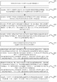
- Step 400 The application layer sends a delay measurement requirement to the OAM unified management center.
- the latency measurement requirements are independent of the network technology.
- Step 410 The OAM unified management center determines that the link to be detected is the link A and the link B according to the delay measurement requirement, and the network technologies adopted by the link A and the link B respectively are the ETH network technology and the IP network technology;
- Step 420 The first specific feature of the difference between the ETH network technology and other network technologies is determined by the OAM unified management center, and the second specific feature of the difference between the IP network technology and other network technologies;
- Step 430 The OAM unified management center converts the delay measurement requirement into network OAM state detection signaling related to the ETH network technology based on the general OAM management data model and the first specific feature, based on the general OAM management data model and the second specific feature. Converting the delay measurement demand map into network OAM state detection signaling related to the IP network technology;
- Step 440 The OAM unified management center sends the converted network OAM status detection signaling related to the ETH network technology to the network entity in the link A, and sends the converted network OAM status detection signaling related to the IP network technology.
- the OAM unified management center sends the converted network OAM status detection signaling related to the ETH network technology to the network entity in the link A, and sends the converted network OAM status detection signaling related to the IP network technology.
- Step 450 The network entity in link A and link B performs time delay measurement according to network OAM state detection signaling.
- Step 460 The network entity in the link A converts the first delay measurement result to the object of the general OAM management data model based on the general OAM management data model, and then converts the object of the general OAM management data model into the data in the XML form.
- the NETCONF is used to send the data to the OAM unified management center; or the network entity in the link A sends the first delay measurement result to the OAM unified management center using the existing ETH OAM management data model, and the OAM unified management center manages the data based on the general OAM.
- a model that converts the first delay measurement result into an object of a general OAM management data model
- Step 470 The network entity in the link B converts the second delay measurement result to the object of the general OAM management data model based on the general OAM management data model, and then converts the object of the general OAM management data model into the data in the XML format.
- the OAM unified management center is sent by the NETCONF; or the network entity in the link B sends the second delay measurement result to the OAM unified management center by using the existing IP OAM management data model, and the OAM unified management center is based on the general OAM management data.
- a model that converts the second delay measurement result into an object of the general OAM management data model
- Step 480 The OAM unified management center processes the object of the received general OAM management data model to obtain a first delay and a second delay, and uses the sum of the first delay and the second delay as the link A and The total delay of link B.
- the OAM unified management center 5000 includes a receiving unit 50 and a processing unit 51, where the following is the technical solution of the foregoing method.
- the embodiment of the present invention provides an OAM unified management center 5000, where:
- the receiving unit 50 is configured to receive the detected network OAM status information sent by the network entity, where the network OAM status information is received by using a general OAM management data model, or by using the network entity based
- the network technology corresponding to the OAM management data model is received in a manner;
- the processing unit 51 is configured to process network OAM state information based on the general OAM management data model
- the general OAM management data model includes unified parameters, and the unified parameters are parameters commonly used in the OAM management data model corresponding to different network technologies.
- the method further includes: a generating unit, configured to: obtain a unified parameter, and generate a general OAM management data model by using the IETF YANG Data Model format.
- the receiving unit 50 is specifically configured to: receive data in an XML format that is transmitted by the network entity by using NETCONF;
- the XML form data is converted by the object of the general OAM management data model, and the object of the general OAM management data model carries the network OAM state information; the object of the general OAM management data model is the OAM unified management center according to the detected network OAM status. Information obtained by populating and/or expanding relevant parameters in the generic OAM management data model.
- the embodiment of the present invention further includes a sending unit, where the sending unit is configured to: send network OAM state detection signaling to the network entity;
- the network OAM state detection signaling is generated according to the general OAM management data model and is related to the network technology adopted by the network entity.
- the receiving unit 50 is further configured to: receive, by the application layer, a network OAM state detection requirement that is not related to the network technology;
- the OAM unified management center further includes a conversion unit for determining specific characteristics of the network technology adopted by the network entity; and converting the network OAM state detection requirement into the network OAM state detection signaling based on the general OAM management data model and specific features.
- the general OAM management data model further includes one or any combination of the following information:
- Network level information of the network layer included in the path of the detected network OAM state Network level information of the network layer included in the path of the detected network OAM state, first association information between the included network layers, relative position information of the path and other paths, and second association information of the path and other paths .
- the sending unit is further configured to: send, to the network entity, OAM configuration information corresponding to the OAM capability information supported by the network entity;
- the OAM configuration information is generated based on the general OAM management data model and the configuration information related to the network technology used by the network entity.
- the processing unit 51 is specifically configured to: determine, between the network entity and another network entity, according to the object of the general OAM management data model. A problem occurs in the first path of the transmitted data stream; the OAM unified management center sends a notification message to the network entity to cause the network entity to switch the data flow from the first path to the second path where the problem does not occur; or
- the processing unit 51 is specifically configured to: convert the network OAM status information into an OAM management data model object based on the general OAM management data model. Determining a first path problem of the data stream transmitted between the network entity and the other network entity according to the object of the general OAM management data model; the OAM unified management center sends a notification message to the network entity, so that the network entity takes the data stream from the first The path is switched to the second path where no problem occurred.
- FIG. 5B is another schematic structural diagram of an OAM unified management center 5000 according to an embodiment of the present invention.
- the device includes a transceiver 500, a communication bus 510, a memory 520, and a processor 530, where:
- the transceiver 500 is configured to receive the detected network OAM status information sent by the network entity, where the network OAM status information is received by using a general OAM management data model, or an OAM management data model corresponding to the network technology adopted by the network entity. Way of receiving;
- a communication bus 510 for connection communication between the processor 530, the transceiver 500, and the memory 520;
- a memory 520 configured to store program code
- the processor 530 is configured to call the program code stored in the memory 520, and perform the following operations:
- the general OAM management data model includes unified parameters, and the unified parameters are parameters commonly used in the OAM management data model corresponding to different network technologies.
- FIG. 6A is a schematic structural diagram of a network entity 6000 according to an embodiment of the present invention.
- the device includes a detecting unit 60 and a sending unit 61, where:
- the detecting unit 60 is configured to detect a network OAM state
- the sending unit 61 is configured to send the detected network OAM status information to the OAM unified management center in a manner of a general OAM management data model, or based on an OAM management data model corresponding to the network technology adopted by the network entity;
- the general OAM management data model includes unified parameters, and the unified parameters are parameters commonly used in the OAM management data model corresponding to different network technologies.
- the detecting unit 60 is specifically configured to: automatically detect a network OAM state
- the network OAM status detection signaling is sent according to the network OAM status detection signaling sent by the OAM unified management center;
- the network entity further includes a receiving unit, where the receiving unit is configured to:
- the detecting unit 60 is specifically configured to: detect a network OAM state according to the network OAM state detection signaling.
- the receiving unit is further configured to receive OAM configuration information that is sent by the OAM unified management center and that corresponds to the OAM capability information supported by the network entity.
- the OAM configuration information is generated based on the general OAM management data model and the configuration information related to the network technology used by the network entity.
- the sending unit 61 is specifically configured to send data in the form of XML transmitted by NETCONF, and the data in the form of XML is converted by the object of the general OAM management data model, and the object of the general OAM management data model is used.
- IETF YANG Data Model format generation the object of the general OAM management data model carries network OAM status information.
- FIG. 6B is another schematic structural diagram of a network entity 6000 according to an embodiment of the present invention.
- the device includes a communication bus 600, a memory 610, and a processor 620, and a transceiver 630, where:
- a communication bus 600 for connection communication between the processor 620, the transceiver 630, and the memory 610;
- a memory 610 configured to store program code
- the processor 620 is configured to call the program code stored in the memory 610, and perform the following operations:
- the transceiver 630 is configured to send the detected network OAM status information to the OAM unified management center in a manner of a general OAM management data model, or based on an OAM management data model corresponding to the network technology adopted by the network entity;
- the general OAM management data model includes unified parameters, and the unified parameters are parameters commonly used in the OAM management data model corresponding to different network technologies.
- a schematic structural diagram of an operation and maintenance management system provided by an embodiment of the present invention includes an OAM unified management center 5000 and a network entity 6000.
- the OAM unified management center processes the network OAM state information based on the general OAM management data model, and the general OAM management data model and the network technology adopted by the network entity. It doesn't matter, so it increases the flexibility of implementing OAM functions and reduces the time consuming.
- the computer program instructions can also be stored in a computer readable memory that can direct a computer or other programmable data processing network entity to operate in a particular manner, such that the instructions stored in the computer readable memory produce an article of manufacture comprising the instruction device.
- the instruction means implements the functions in one or more blocks of a flow or a flow diagram and/or a block diagram of the flowchart.
Abstract
本发明公开了一种实现OAM功能的方法及装置,在该方案中,OAM统一管理中心基于通用OAM管理数据模型对网络OAM状态信息进行处理,而通用OAM管理数据模型与网络实体所采用的网络技术无关,因此,提高了实现OAM功能的的灵活性,降低了耗时。
Description
本申请要求于2014年10月23日提交中国专利局、申请号为201410571176.2、发明名称为“一种实现操作管理维护功能的方法及装置”的中国专利申请的优先权,其全部内容通过引用结合在本申请中。
本发明涉及通信技术领域,特别涉及一种实现操作管理维护功能的方法及装置。
当前,在IP(Internet Protocol,互联网协议)承载网中,OAM(Operation Administration Maintenance,操作管理维护)技术已经普遍的使用以及部署,OAM技术主要可以实现如下功能:
1)性能监控并产生维护信息,根据这些信息评估链路的稳定性;
2)通过定期查询的方式检测网络故障,产生各种维护和告警信息;
3)通过调度或者切换到其它的实体,旁路失效实体,保证网络的正常运行;
4)将故障信息传递给管理网络实体。
现有技术中,管理网络实体中的OAM管理数据模型与相应的网络技术强耦合,针对每一种新的网络技术,需要开发新的OAM管理数据模型。例如,如果网络实体之间采用IP网络技术,OAM管理数据模型为IP OAM管理数据模型,如果网络实体之间采用ETH网络技术,OAM管理数据模型为ETH OAM管理数据模型,如果网络实体之间采用MPLS(Multi-Protocol Label Switching,多协议标签交换)网络技术,OAM管理数据模型为MPLS OAM管理数据模型,如图1所示。
随着通信技术的发展,网络实体之间所采用的技术呈现多样化,若有新的网络技术出现,需要先开发新的OAM管理数据模型,然后才能实现OAM功能,因此,目前实现OAM功能的方式存在所耗费的时间较长,且灵活性较低的缺陷。
发明内容
本发明实施例提供一种实现OAM功能的方法及装置,用以解决现有技术中存在的灵活性较差和耗时较长的缺陷。
第一方面,提供一种实现操作管理维护OAM功能的方法,包括:
OAM统一管理中心接收网络实体发送的检测到的网络OAM状态信息,所述网络OAM状态信息使用基于通用OAM管理数据模型的方式接收,或者使用基于与所述网络实体采用的网络技术对应的OAM管理数据模型的方式接收;
所述OAM统一管理中心基于所述通用OAM管理数据模型对所述网络OAM状态信息进行处理;
其中,所述通用OAM管理数据模型包括统一参数,所述统一参数是与采用不同的网络技术分别对应的OAM管理数据模型中共同使用的参数。
结合第一方面,在第一种可能的实现方式中,所述OAM统一管理中心基于所述通用OAM管理数据模型对所述网络OAM状态信息进行处理之前,还包括:
所述OAM统一管理中心获取所述统一参数;
所述OAM统一管理中心采用IETF YANG Data Model格式将所述统一参数生成所述通用OAM管理数据模型。
结合第一方面,或者第一方面的第一种可能的实现方式,在第二种可能的实现方式中,所述使用基于所述通用OAM管理数据模型的方式接收,具体包括:
所述OAM统一管理中心接收所述网络实体采用网络配置协议NETCONF传递的XML形式的数据;
其中,所述XML形式的数据由所述通用OAM管理数据模型的对象转换而来,所述通用OAM管理数据模型的对象携带所述网络OAM状态信息;所述通用OAM管理数据模型的对象是所述OAM统一管理中心根据检测到的所述网络OAM状态信息对所述通用OAM管理数据模型中的相关参数进行填充和/或扩展得到的。
结合第一方面,或者第一方面的第一至第二种可能的实现方式,在第三种可能的实现方式中,所述OAM统一管理中心接收所述网络OAM状态信息之前,还包括:
所述OAM统一管理中心向所述网络实体发送网络OAM状态检测信令;
其中,所述网络OAM状态检测信令是根据所述通用OAM管理数据模型生成的,且与所述网络实体采用的网络技术相关。
结合第一方面的第三种可能的实现方式,在第四种可能的实现方式中,所述OAM统一管理中心向所述网络实体发送网络OAM状态检测信令之前,还包括:
所述OAM统一管理中心接收应用层发送的与网络技术无关的网络OAM状态检测需求;
所述OAM统一管理中心确定所述网络实体所采用的网络技术的特定特征;
所述OAM统一管理中心基于所述通用OAM管理数据模型、所述特定特征,将所述网络OAM状态检测需求转换为所述网络OAM状态检测信令。
结合第一方面,或者第一方面的第一至第四种可能的实现方式,在第五种可能的实现方式中,所述通用OAM管理数据模型还包括如下信息中的一种或者任意组合:
被检测网络OAM状态的路径所包括的网络层次的网络层次信息、所包括的网络层次之间的第一关联信息、所述路径与其他路径的相对位置信息、所述路径与其他路径的第二关联信息。
结合第一方面,或者第一方面的第一至第五种可能的实现方式,在第六种可能的实现方式中,所述OAM统一管理中心基于所述通用OAM管理数据模型对所述网络OAM状态信息进行处理,具体包括:
若所述网络OAM状态信息使用基于通用OAM管理数据模型的方式接收,所述OAM统一管理中心根据所述通用OAM管理数据模型的对象确定所述网络实体和其他网络实体之间传输的数据流的第一路径发生问题;所述OAM统一管理中心向所述网络实体发送通知消息,以使得所述网络实体将所述数据流从所述第一路径切换至未发生问题的第二路径中传输;或者
若所述网络OAM状态信息使用基于与所述网络实体采用的网络技术对应的OAM管理数据模型的方式接收,所述OAM统一管理中心基于所述通用OAM管理数据模型将所述网络OAM状态信息转换为所述通用OAM管理数据模型的对象,根据所述通用OAM管理数据模型的对象确定所述网络实体和其他网络实体之间传输的数据流的第一路径发生问题;所述OAM统一管理中心向所述网络实体发送通知消息,以使得所述网络实体将所述数据流从所述第一路径切换至未发生问题的第二路径中传输。
第二方面,提供一种操作管理维护OAM统一管理中心,包括:
接收单元,用于接收网络实体发送的检测到的网络OAM状态信息,所述网络OAM状态信息使用基于通用OAM管理数据模型的方式接收,或者使用基于与所述网络实体采用的网络技术对应的OAM管理数据模型的方式接收;
处理单元,用于基于所述通用OAM管理数据模型对所述网络OAM状态信息进行处理;
其中,所述通用OAM管理数据模型包括统一参数,所述统一参数是与采用不同的网络技术分别对应的OAM管理数据模型中共同使用的参数。
结合第二方面,在第一种可能的实现方式中,还包括生成单元,所述生成单元用于:
获取所述统一参数,采用IETF YANG Data Model格式将所述统一参数生成所述通用OAM管理数据模型。
结合第二方面,或者第二方面的第一种可能的实现方式,在第二种可能的实现方式中,所述接收单元具体用于:接收所述网络实体采用网络配置协议NETCONF传递的XML形式的数据;
其中,所述XML形式的数据由所述通用OAM管理数据模型的对象转换而来,所述通用OAM管理数据模型的对象携带所述网络OAM状态信息;所述通用OAM管理数据模型的对象是所述OAM统一管理中心根据检测到的所述网络OAM状态信息对所述通用OAM管理数据模型中的相关参数进行填充和/或扩展得到的。
结合第二方面,或者第二方面的第一至第二种可能的实现方式,在第三种可能的实现方式中,还包括发送单元,所述发送单元用于:向所述网络实体发送网络OAM状态检测信令;
其中,所述网络OAM状态检测信令是根据所述通用OAM管理数据模型生成的,且与所述网络实体采用的网络技术相关。
结合第二方面的第三种可能的实现方式,在第四种可能的实现方式中,所述接收单元还用于:接收应用层发送的与网络技术无关的网络OAM状态检测需求;
所述OAM统一管理中心还包括转换单元,用于确定所述网络实体所采用的网络技术的特定特征;基于所述通用OAM管理数据模型、所述特定特征,将所述网络OAM状态检测需求转换为所述网络OAM状态检测信令。
结合第二方面,或者第二方面的第一至第四种可能的实现方式,在第五种可能的实现方式中,所述通用OAM管理数据模型还包括如下信息中的一种或者任意组合:
被检测网络OAM状态的路径所包括的网络层次的网络层次信息、所包括的网络层次之间的第一关联信息、所述路径与其他路径的相对位置信息、所述路径与其他路径的第二关联信息中的。
结合第二方面,或者第二方面的第一至第五种可能的实现方式,在第六种可能的实现方式中,所述发送单元还用于:向所述网络实体发送与所述网络实体所支持的OAM能力信息相对应的OAM配置信息;
其中,所述OAM配置信息是基于所述通用OAM管理数据模型,增加与所述网络实体所采用的网络技术相关的配置信息生成的。
结合第二方面,或者第二方面的第一至第六种可能的实现方式,在第七种可能的实
现方式中,若所述网络OAM状态信息使用基于通用OAM管理数据模型的方式接收,所述处理单元具体用于:根据通用OAM管理数据模型的对象确定所述网络实体和其他网络实体之间传输的数据流的第一路径发生问题;所述OAM统一管理中心向所述网络实体发送通知消息,以使得所述网络实体将所述数据流从所述第一路径切换至未发生问题的第二路径中传输;或者
若所述网络OAM状态信息使用基于与所述网络实体采用的网络技术对应的OAM管理数据模型的方式接收,所述处理单元具体用于:基于通用OAM管理数据模型将所述网络OAM状态信息转换为OAM管理数据模型的对象,根据通用OAM管理数据模型的对象确定所述网络实体和其他网络实体之间传输的数据流的第一路径发生问题;所述OAM统一管理中心向所述网络实体发送通知消息,以使得所述网络实体将所述数据流从所述第一路径切换至未发生问题的第二路径中传输。
第三方面,提供一种网络实体,包括:
检测单元,用于检测网络OAM状态;
发送单元,用于将检测到的网络OAM状态信息基于通用OAM管理数据模型的方式,或者基于与所述网络实体采用的网络技术对应的OAM管理数据模型的方式发送至OAM统一管理中心;
其中,所述通用OAM管理数据模型包括统一参数,所述统一参数是与采用不同的网络技术分别对应的OAM管理数据模型中共同使用的参数。
结合第三方面,在第一种可能的实现方式中,所述检测单元具体用于:自发检测网络OAM状态;
或者,根据所述OAM统一管理中心发送的网络OAM状态检测信令检测网络OAM状态;则所述网络实体还包括接收单元,所述接收单元用于:
接收所述OAM统一管理中心发送的所述网络OAM状态检测信令,所述网络OAM状态检测信令是所述OAM统一管理中心基于所述通用OAM管理数据模型生成的、且与所述网络实体所采用的网络技术相关的;
所述检测单元具体用于:根据所述网络OAM状态检测信令检测网络OAM状态。
结合第三方面,或者第三方面的第一种可能的实现方式,在第二种可能的实现方式中,所述接收单元还用于接收所述OAM统一管理中心发送的与所述网络实体所支持的OAM能力信息相对应的OAM配置信息;
其中,所述OAM配置信息是基于所述通用OAM管理数据模型,增加与所述网络
实体所采用的网络技术相关的配置信息生成的。
结合第三方面,或者第三方面的第一至第二种可能的实现方式,在第三种可能的实现方式中,所述发送单元具体用于发送采用网络配置协议NETCONF传递的XML形式的数据,所述XML形式的数据由所述通用OAM管理数据模型的对象转换而来,所述通用OAM管理数据模型使用IETF YANG Data Model格式生成,所述通用OAM管理数据模型的对象携带所述网络OAM状态信息。
第四方面,提供一种操作维护管理系统,包括第二方面,或者第二方面的各种可能的实现方式所述的OAM统一管理中心、如第三方面,或者第三方面的各种可能的实现方式所述的网络实体。
本发明实施例中,OAM统一管理中心基于通用OAM管理数据模型对网络OAM状态信息进行处理,而通用OAM管理数据模型与网络实体所采用的网络技术无关,因此,提高了实现OAM功能的的灵活性,降低了耗时。
图1为现有技术中实现OAM功能的示意图;
图2A为本发明实施例中实现OAM功能的一种流程图;
图2B为本发明实施例中应用层、OAM统一管理中心和网络实体之间的示意图;
图2C为本发明实施例中OAM统一管理中心和MP的示意图;
图3为本发明实施例中实现OAM功能的另一种流程图;
图4A为本发明实施例中实现OAM功能的实施例的应用场景图;
图4B为本发明实施例中实现OAM功能的一种实施例;
图5A为本发明实施例中OAM统一管理中心的一种结构示意图;
图5B为本发明实施例中OAM统一管理中心的另一种结构示意图;
图6A为本发明实施例中网络实体的一种结构示意图;
图6B为本发明实施例中网络实体的另一种结构示意图;
图7为本发明实施例中操作维护管理系统的结构示意图。
为使本发明实施例的目的、技术方案和优点更加清楚,下面将结合本发明实施例中的附图,对本发明实施例中的技术方案进行清楚、完整地描述,显然,所描述的实施例是本发明一部分实施例,而不是全部的实施例。基于本发明中的实施例,本领域普通技
术人员在没有作出创造性劳动前提下所获得的所有其他实施例,都属于本发明保护的范围。
另外,本文中术语“系统”和“网络”在本文中常被可互换使用。本文中术语“和/或”,仅仅是一种描述关联对象的关联关系,表示可以存在三种关系,例如,A和/或B,可以表示:单独存在A,同时存在A和B,单独存在B这三种情况。另外,本文中字母“/”,一般表示前后关联对象是一种“或”的关系。
下面结合说明书附图对本发明优选的实施方式进行详细说明,应当理解,此处所描述的优选实施例仅用于说明和解释本发明,并不用于限定本发明,并且在不冲突的情况下,本申请中的实施例及实施例中的特征可以相互组合。
下面结合附图对本发明优选的实施方式进行详细说明。
参阅图2A所示,本发明实施例中,实现OAM的一种详细流程如下:
步骤200:OAM统一管理中心接收网络实体发送的检测到的网络OAM状态信息,网络OAM状态信息使用基于通用OAM管理数据模型的方式接收,或者使用基于与网络实体采用的网络技术对应的OAM管理数据模型的方式接收;
步骤210:OAM统一管理中心基于通用OAM管理数据模型对网络OAM状态信息进行处理;其中,通用OAM管理数据模型包括统一参数,统一参数是与采用不同的网络技术分别对应的OAM管理数据模型中共同使用的参数。
本发明实施例中,OAM统一管理中心收集该OAM统一管理中心管理的网络中各个MP(Maintenance Point,管理维护节点)的信息,MP的信息包括MP的网络拓扑信息和使用的OAM技术信息。
本发明实施例中,设置OAM统一管理中心对网络进行统一管理,该OAM统一管理中心是个逻辑的概念,可以为集中式的,物理上可以是个独立的网络实体,或者内置在网络实体中,如多个交换机或路由器上;也可以是分布式的,物理上是多个独立的网络实体,或者内置在多个网络实体中,如多个交换机或路由器上。
本发明实施例中,网络实体检测网络OAM状态,实际上是网络实体中的MP来执行的,MP具体执行OAM检测或OAM测量,MP也是个逻辑的概念,物理上可以设置在网络实体上,如交换机或路由器上,一台网络实体上可以设置一个或多个MP,一台网络实体上的多个MP也可以分别使用不同的OAM技术。
本发明实施例中,OAM统一管理中心基于通用OAM管理数据模型对网络OAM状态信息进行处理之前,要生成通用OAM管理数据模型,其中,生成通用OAM管理数
据模型的方式可以采用如下方式:
OAM统一管理中心获取统一参数;
OAM统一管理中心将统一参数采用IETF YANG Data Model格式生成通用OAM管理数据模型。
本发明实施例中,通用OAM管理数据模型的代码格式可以如下:

本发明实施例中,网络OAM状态可以包括多种内容,如包括链路故障的状态、链路性能下降的状态,其中,可选的,链路性能下降可以指链路损耗、链路丢包、链路连通性下降、链路延迟变大中的一种或者任意组合,本发明实施例中,网络实体将检测到的网络OAM状态信息发送给OAM统一管理中心。
本发明实施例中,使用基于通用OAM管理数据模型的方式接收的方式有多种,可选的,可以采用如下方式:
OAM统一管理中心接收网络实体采用NETCONF(Network Configuration Protocol,网络配置协议)传递的XML形式的数据;
其中,XML形式的数据由通用OAM管理数据模型的对象转换而来,通用OAM管理数据模型的对象携带网络OAM状态信息;通用OAM管理数据模型的对象是OAM统一管理中心根据检测到的网络OAM状态信息,对通用OAM管理数据模型中的相关参数进行填充和/或扩展得到的。
也就是说,通用OAM管理数据模型的对象是根据具体实例对通用OAM管理数据模型中包括的相关参数进行填充和/或扩展得到。具体实例可能与网络实体采用的具体的网络技术相关,也可能不相关,例如,可以根据网络OAM状态信息,对通用OAM管理数据模型中包括的相关参数进行填充和/或扩展得到通用OAM管理数据模型的对象。
本发明实施例中,将通用OAM管理数据模型的对象转换成XML形式的数据可以采用现有的标准的规则,在此不再进行一一详述。
本发明实施例中,通用OAM管理数据模型是对与现有各种网络技术对应的OAM管理数据模型,如:IP OAM管理数据模型、ETH OAM管理数据模型、MPLS OAM管理数据模型等,所采用的共同参数的抽象和提炼而生成的,与具体OAM技术解耦合,若有新的网络技术产生,可以继承和扩展本发明实施例中提到的通用OAM管理数据模型,而不必要再产生一个全新的OAM管理数据模型,因此,提高了实现OAM功能的的灵活性,降低了耗时。
本发明实施例中,OAM统一管理中心接收网络OAM状态信息之前,还可以包括如下操作:
OAM统一管理中心向网络实体发送网络OAM状态检测信令;
其中,网络OAM状态检测信令是根据通用OAM管理数据模型生成的,且与网络实体采用的网络技术相关。
本发明实施例中,OAM统一管理中心向网络实体发送网络OAM状态检测信令之
前,还包括:
向网络实体发送OAM能力请求;
接收网络实体根据OAM能力请求发送的网络实体所支持的OAM能力信息。
本发明实施例中,OAM统一管理中心向网络实体发送网络OAM状态检测信令的触发条件可以是OAM统一管理中心自发发送网络OAM状态检测信令,也可以是应用层给OAM统一管理中心发送触发条件,例如:
OAM统一管理中心接收应用层发送的与网络技术无关的网络OAM状态检测需求;
OAM统一管理中心确定网络实体所采用的网络技术的特定特征;
OAM统一管理中心基于通用OAM管理数据模型、特定特征,将网络OAM状态检测需求转换为网络OAM状态检测信令。
其中,本发明实施例中的应用层、OAM统一管理数据模型和网络实体的架构如图2B所示。
例如,网络实体为采用IP技术的网络实体,OAM统一管理中心接收到应用层发送的网络OAM状态检测需求时,先确定目的网络实体,并确定目的网络实体所采用的网络技术为IP技术,然后,确定IP技术所特有的特定特征,将网络OAM状态检测需求根据通用OAM管理数据模型、IP技术所特有的特定特征将网络OAM状态检测需求转换为与IP网络技术相关的网络OAM状态检测信令。
本发明实施例中,应用层可以将与具体网络技术无关的网络OAM状态检测需求基于通用OAM管理数据模型的方式发送给OAM统一管理中心,也可以是应用层将与具体网络技术无关的网络OAM状态检测需求,采用不是基于通用OAM管理数据模型的方式发送给OAM统一管理中心。具体发送方式本发明不加以限定,都属于本发明的保护范围。
现有技术中,应用层将网络OAM状态检测需求发送至网络实体时,要先了解网络实体所采用的网络技术,然后,应用层将网络OAM状态检测需求转换为与网络实体所采用的网络技术相关的网络OAM状态检测需求,这样,应用层需要了解接收网络OAM状态检测需求的网络实体所采用的网络技术,而本发明实施例中,应用层无需了解接收网络OAM状态检测需求的网络实体所采用的网络技术,OAM统一管理中心可以实现网络OAM状态检测需求转换为网络OAM状态检测信令,实现统一管理,解除应用层对具体网络技术的依赖。
例如,现有技术中,如需要采用IP网络技术的网络实体执行CC功能时,网络OAM
状态检测需求中要携带目的IP地址、目的IP接口、BFD的信息;如需要采用ETH网络技术的网络实体执行CC功能时,网络OAM状态检测需求中携带目的ETH地址、目的ETH接口、MPLS BFD的信息;而本发明实施例中,可以携带网络实体的标识,OAM统一管理中心基于网络实体的标识确定相应的信息。
本发明实施例中,OAM统一管理中心可以基于通用OAM管理数据模型实现CC、CV、PM、Path Discovery等功能。
本发明实施例中,通用OAM管理数据模型还包括如下信息中的一种或者任意组合:
被检测网络OAM状态的路径所包括的网络层次的网络层次信息、所包括的网络层次之间的第一关联信息、路径与其他路径的相对位置信息、路径与其他路径的第二关联信息,这样,OAM统一管理中心可以支持跨层跨域的OAM交互,从而实现跨域跨层的OAM故障检测。
本发明实施例中,OAM统一管理中心接收到通用OAM管理数据模型的对象或者网络OAM状态之前,还包括如下操作:
OAM统一管理中心向网络实体发送与网络实体所支持的OAM能力信息相对应的OAM配置信息;
其中,OAM配置信息是基于通用OAM管理数据模型,增加与网络实体所采用的网络技术相关的配置信息生成的。
本发明实施例中,OAM统一管理中心基于通用OAM管理数据模型对网络OAM状态信息进行处理时,可以采用如下方式:
若网络OAM状态信息使用基于通用OAM管理数据模型的方式接收,OAM统一管理中心根据通用OAM管理数据模型的对象确定网络实体和其他网络实体之间传输的数据流的第一路径发生问题;OAM统一管理中心向网络实体发送通知消息,以使得网络实体将数据流从第一路径切换至未发生问题的第二路径中传输;或者
若网络OAM状态信息使用基于与网络实体采用的网络技术对应的OAM管理数据模型的方式接收,OAM统一管理中心基于通用OAM管理数据模型将网络OAM状态信息转换为通用OAM管理数据模型的对象,根据通用OAM管理数据模型的对象确定网络实体和其他网络实体之间传输的数据流的第一路径发生问题;OAM统一管理中心向网络实体发送通知消息,以使得网络实体将数据流从第一路径切换至未发生问题的第二路径中传输。
如图2C所示,源网络实体和目的网络实体之间有三条路径:路径1:R1-Ra-Rd-R2、
路径2:R1-Rb-Rd-R2、路径3:R1-Rc-Re-R2,若源网络实体和目的网络实体之间的数据流是通过路径1传输,OAM统一管理中心根据R1发送的通用OAM管理数据模型的对象确定路径1发生问题时,所述的问题可以为性能问题、丢包问题等,OAM统一管理中心向R1发送通知消息,然后,R1将数据流从路径1切换至未发生问题的路径2和路径3中的一条路径上。
本发明实施例中,OAM统一管理中心基于通用OAM管理数据模型对网络OAM状态信息进行处理的方式有多种,可选的,可以采用如下方式:
根据网络层次信息、第一关联信息、相对位置信息、第二关联信息进行跨域和跨层的汇总、关联和统一分析,呈现端到端OAM视图。
本发明实施例中,呈现端到端OAM视图的方式有多种,可选的,可以采用如下方式:
呈现发生网络故障或缺陷的路径在网络中所处的网络层次的网络层次信息和/或所处的与其他路径的相对位置信息;或者
呈现网络端到端的性能监控结果。
本发明实施例中,根据网络层次信息、第一关联信息、相对位置信息、第二关联信息进行跨网段和跨层的汇总、关联和统一分析之后,进一步的,还包括:
执行OAM统一调度。
本发明实施例中,执行OAM统一调度的方式有多种,可选的,可以采用如下方式:
根据第一关联信息确定关联网络层次;和/或
根据第二关联信息确定关联路径;
根据关联网络层次和/或关联路径,以及相对位置信息,确定关联网络实体;
向关联网络实体下发与其所采用的网络技术相关的网络OAM状态检测信令,以使得关联网络实体执行OAM功能,并发送执行OAM功能后的结果。
参阅图3所示,本发明实施例中,实现OAM功能的另一种详细流程如下:
步骤300:网络实体检测网络OAM状态;
步骤310:网络实体将检测到的网络OAM状态信息基于通用OAM管理数据模型的方式,或者基于与网络实体采用的网络技术对应的OAM管理数据模型的方式发送至OAM统一管理中心,其中,通用OAM管理数据模型包括统一参数,统一参数是与采用不同的网络技术分别对应的OAM管理数据模型中共同使用的参数。
本发明实施例中,网络OAM状态可以包括多种内容,如包括链路故障的状态、链
路性能下降的状态,其中,可选的,链路性能下降可以指链路损耗、链路丢包、链路连通性下降、链路延迟变大中的一种或者任意组合,本发明实施例中,网络实体将检测到的网络OAM状态信息发送给OAM统一管理中心。
本发明实施例中,触发网络实体检测网络OAM状态的方式有多种,可选的,可以采用如下方式:
网络实体自发检测网络OAM状态。
或者,也可以是在OAM统一管理中心的触发下检测网络OAM状态,实现时,可以采用如下方式:
网络实体接收OAM统一管理中心发送的网络OAM状态检测信令,网络OAM状态检测信令是OAM统一管理中心基于通用OAM管理数据模型生成的、且与网络实体所采用的网络技术相关的;
网络实体根据网络OAM状态检测信令检测网络OAM状态。
当然,还有其他触发条件,在此不再进行一一详述。
可选的,还接收OAM统一管理中心发送的与网络实体所支持的OAM能力信息相对应的OAM配置信息;
其中,OAM配置信息是基于通用OAM管理数据模型,增加与网络实体所采用的网络技术相关的配置信息生成的。
本发明实施例中,网络实体在接收OAM统一管理中心发送的网络OAM状态检测信令之前,还可以包括如下操作:
网络实体接收OAM统一管理中心发送的OAM能力请求;
网络实体根据OAM能力请求向OAM统一管理中心发送网络实体支持的OAM能力信息。
本发明实施例中,可选的,OAM能力信息包括网络实体所支持的OAM功能、网络实体所支持的网络承载协议、网络实体是否支持组播OAM等信息。当然,还可以包括其他信息,在此不再进行一一详述。
本发明实施例中,OAM统一管理中心收集该OAM统一管理中心管理的网络中各个MP的信息,MP的信息包括MP的网络拓扑信息和使用的OAM技术信息。
本发明实施例中,设置OAM统一管理中心对网络进行统一管理,该OAM统一管理中心是个逻辑的概念,可以为集中式的,物理上可以是个独立的网络实体,或者内置在网络实体中,如多个交换机或路由器上;也可以是分布式的,物理上是多个独立的网
络实体,或者内置在多个网络实体中,如多个交换机或路由器上。
本发明实施例中,网络实体检测网络OAM状态,实际上是网络实体中的MP来执行的,MP具体执行OAM检测或OAM测量,MP也是个逻辑的概念,物理上可以设置在网络实体上,如交换机或路由器上,一台网络实体上可以设置一个或多个MP,一台网络实体上的多个MP也可以分别使用不同的OAM技术。
本发明实施例中,可选的,通用OAM管理数据模型可以采用如下方式生成,例如:
获取与各种网络技术分别对应的OAM管理数据模型共同采用的参数;
将获取的参数采用IETF YANG Data Model格式生成通用OAM管理数据模型。
本发明实施例中,通用OAM管理数据模型的代码格式可以如下:


本发明实施例中,通用OAM管理数据模型的对象是根据具体实例对通用OAM管理数据模型中包括的相关参数进行填充和/或扩展得到。具体实例可能与MP采用的具体网络技术相关,也可能不相关。例如,可以根据网络OAM状态信息,对通用OAM管理数据模型中包括的相关参数进行填充和/或扩展得到通用OAM管理数据模型的对象。本发明实施例中,进一步的,还可以将通用OAM管理数据模型的对象转换成XML形式的数据,然后,将XML形式的数据采用NETCONF传递至OAM统一管理中心,其中,将通用OAM管理数据模型的对象转换XML形式的数据可以采用现有的标准的规则,在此不再进行一一详述。本发明实施例中,为了提高OAM处理的效率,通用OAM管理数据模型还包括如下信息中的一种或者任意组合:
被检测网络OAM状态的路径所包括的网络层次的网络层次信息、所包括的网络层次之间的第一关联信息、路径与其他路径的相对位置信息、路径与其他路径的第二关联信息,这样,网络OAM状态信息后,根据网络层次信息、第一关联信息、相对位置信息和第二关联信息可以快速进行处理。
本发明实施例中,通用OAM管理数据模型是对与现有各种网络技术对应的OAM管理数据模型,如:IP OAM管理数据模型、ETH OAM管理数据模型、MPLS OAM管理数据模型等,所采用的共同参数的抽象和提炼而生成的,与具体网络技术解耦合若有新的网络技术产生,可以继承和扩展现有通用OAM管理数据模型,而不必要再产生一个全新的OAM管理数据模型,OAM统一管理中心基于通用OAM管理数据模型对网络OAM状态信息进行处理,而通用OAM管理数据模型与网络实体所采用的网络技术无关,因此,提高了实现OAM功能的的灵活性,降低了耗时。
为了更好地理解本发明实施例,以下给出具体应用场景,如图4A所示,针对实现OAM功能的过程,作出进一步详细描述,如图4B所示:
步骤400:应用层给OAM统一管理中心发送时延测量需求;
在该步骤中,时延测量需求与网络技术无关。
步骤410:OAM统一管理中心根据时延测量需求确定待检测的链路为链路A和链路B,及链路A和链路B分别采用的网络技术为ETH网络技术和IP网络技术;
步骤420:OAM统一管理中心确定ETH网络技术与其他网络技术的区别的第一特定特征,IP网络技术与其他网络技术的区别的第二特定特征;
步骤430:OAM统一管理中心基于通用OAM管理数据模型、第一特定特征,将时延测量需求转换为与ETH网络技术相关的网络OAM状态检测信令,基于通用OAM管理数据模型、第二特定特征,将时延测量需求映射转换为与IP网络技术相关的网络OAM状态检测信令;
步骤440:OAM统一管理中心将转换得到的与ETH网络技术相关的网络OAM状态检测信令发送至链路A中的网络实体,将转换得到的与IP网络技术相关的网络OAM状态检测信令发送至链路B中的网络实体;
步骤450:链路A和链路B中的网络实体根据网络OAM状态检测信令进行时延测量;
步骤460:链路A中的网络实体将第一时延测量结果基于通用OAM管理数据模型,转换为通用OAM管理数据模型的对象,再将通用OAM管理数据模型的对象转换为XML形式的数据,采用NETCONF发送至OAM统一管理中心;或者链路A中的网络实体将第一时延测量结果采用现有的ETH OAM管理数据模型发送给OAM统一管理中心,由OAM统一管理中心基于通用OAM管理数据模型,将第一时延测量结果转换为通用OAM管理数据模型的对象;
步骤470:链路B中的网络实体将第二时延测量结果基于通用OAM管理数据模型,转换为通用OAM管理数据模型的对象,再将通用OAM管理数据模型的对象转换为XML形式的数据,采用NETCONF发送至OAM统一管理中心;或者链路B中的网络实体将第二时延测量结果采用现有的IP OAM管理数据模型发送给OAM统一管理中心,由OAM统一管理中心基于通用OAM管理数据模型,将第二时延测量结果转换为通用OAM管理数据模型的对象;
步骤480:OAM统一管理中心对接收到的通用OAM管理数据模型的对象进行处理,得到第一时延和第二时延,并将第一时延和第二时延之和作为链路A和链路B的总时延。
基于上述相应方法的技术方案,参阅图5A所示,本发明实施例提供一种OAM统一管理中心5000,该OAM统一管理中心5000包括接收单元50、处理单元51,其中:
接收单元50,用于接收网络实体发送的检测到的网络OAM状态信息,网络OAM状态信息使用基于通用OAM管理数据模型的方式接收,或者使用基于与网络实体采用
的网络技术对应的OAM管理数据模型的方式接收;
处理单元51,用于基于通用OAM管理数据模型对网络OAM状态信息进行处理;
其中,通用OAM管理数据模型包括统一参数,统一参数是与采用不同的网络技术分别对应的OAM管理数据模型中共同使用的参数。
本发明实施例中,进一步的,还包括生成单元,生成单元用于:获取统一参数,采用IETF YANG Data Model格式将统一参数生成通用OAM管理数据模型。
本发明实施例中,可选的,接收单元50具体用于:接收网络实体采用NETCONF传递的XML形式的数据;
其中,XML形式的数据由通用OAM管理数据模型的对象转换而来,通用OAM管理数据模型的对象携带网络OAM状态信息;通用OAM管理数据模型的对象是OAM统一管理中心根据检测到的网络OAM状态信息,对通用OAM管理数据模型中的相关参数进行填充和/或扩展得到的。
本发明实施例中,进一步的,还包括发送单元,发送单元用于:向网络实体发送网络OAM状态检测信令;
其中,网络OAM状态检测信令是根据通用OAM管理数据模型生成的,且与网络实体采用的网络技术相关。
本发明实施例中,进一步的,接收单元50还用于:接收应用层发送的与网络技术无关的网络OAM状态检测需求;
OAM统一管理中心还包括转换单元,用于确定网络实体所采用的网络技术的特定特征;基于通用OAM管理数据模型、特定特征,将网络OAM状态检测需求转换为网络OAM状态检测信令。
本发明实施例中,可选的,通用OAM管理数据模型还包括如下信息中的一种或者任意组合:
被检测网络OAM状态的路径所包括的网络层次的网络层次信息、所包括的网络层次之间的第一关联信息、路径与其他路径的相对位置信息、路径与其他路径的第二关联信息中的。
本发明实施例中,进一步的,发送单元还用于:向网络实体发送与网络实体所支持的OAM能力信息相对应的OAM配置信息;
其中,OAM配置信息是基于通用OAM管理数据模型,增加与网络实体所采用的网络技术相关的配置信息生成的。
本发明实施例中,可选的,若网络OAM状态信息使用基于通用OAM管理数据模型的方式接收,处理单元51具体用于:根据通用OAM管理数据模型的对象确定网络实体和其他网络实体之间传输的数据流的第一路径发生问题;OAM统一管理中心向网络实体发送通知消息,以使得网络实体将数据流从第一路径切换至未发生问题的第二路径中传输;或者
若网络OAM状态信息使用基于与网络实体采用的网络技术对应的OAM管理数据模型的方式接收,处理单元51具体用于:基于通用OAM管理数据模型将网络OAM状态信息转换为OAM管理数据模型的对象,根据通用OAM管理数据模型的对象确定网络实体和其他网络实体之间传输的数据流的第一路径发生问题;OAM统一管理中心向网络实体发送通知消息,以使得网络实体将数据流从第一路径切换至未发生问题的第二路径中传输。
如图5B所示,为本发明实施例提供的OAM统一管理中心5000的另一种结构示意图,该装置包括收发器500、通信总线510、存储器520及处理器530,其中:
收发器500,用于接收网络实体发送的检测到的网络OAM状态信息,网络OAM状态信息使用基于通用OAM管理数据模型的方式接收,或者使用基于与网络实体采用的网络技术对应的OAM管理数据模型的方式接收;
通信总线510,用于处理器530、收发器500及存储器520之间的连接通信;
存储器520,用于存储程序代码;
处理器530,用于调用存储器520中存储的程序代码,并执行如下操作:
基于通用OAM管理数据模型对网络OAM状态信息进行处理;
其中,通用OAM管理数据模型包括统一参数,统一参数是与采用不同的网络技术分别对应的OAM管理数据模型中共同使用的参数。
如图6A所示,为本发明实施例提供的网络实体6000的一种结构示意图,该装置包括检测单元60、发送单元61,其中:
检测单元60,用于检测网络OAM状态;
发送单元61,用于将检测到的网络OAM状态信息基于通用OAM管理数据模型的方式,或者基于与网络实体采用的网络技术对应的OAM管理数据模型的方式发送至OAM统一管理中心;
其中,通用OAM管理数据模型包括统一参数,统一参数是与采用不同的网络技术分别对应的OAM管理数据模型中共同使用的参数。
本发明实施例中,可选的,检测单元60具体用于:自发检测网络OAM状态;
或者,根据OAM统一管理中心发送的网络OAM状态检测信令检测网络OAM状态;则网络实体还包括接收单元,接收单元用于:
接收OAM统一管理中心发送的网络OAM状态检测信令,网络OAM状态检测信令是OAM统一管理中心基于通用OAM管理数据模型生成的、且与网络实体所采用的网络技术相关的;
检测单元60具体用于:根据网络OAM状态检测信令检测网络OAM状态。
本发明实施例中,进一步的,接收单元还用于接收OAM统一管理中心发送的与网络实体所支持的OAM能力信息相对应的OAM配置信息;
其中,OAM配置信息是基于通用OAM管理数据模型,增加与网络实体所采用的网络技术相关的配置信息生成的。
本发明实施例中,可选的,发送单元61具体用于发送采用NETCONF传递的XML形式的数据,XML形式的数据由通用OAM管理数据模型的对象转换而来,通用OAM管理数据模型的对象使用IETF YANG Data Model格式生成,通用OAM管理数据模型的对象携带网络OAM状态信息。
如图6B所示,为本发明实施例提供的网络实体6000的另一种结构示意图,该装置包括通信总线600、存储器610及处理器620,及收发器630,其中:
通信总线600,用于处理器620、收发器630及存储器610之间的连接通信;
存储器610,用于存储程序代码;
处理器620,用于调用存储器610中存储的程序代码,并执行如下操作:
检测网络OAM状态;
收发器630,用于将检测到的网络OAM状态信息基于通用OAM管理数据模型的方式,或者基于与网络实体采用的网络技术对应的OAM管理数据模型的方式发送至OAM统一管理中心;
其中,通用OAM管理数据模型包括统一参数,统一参数是与采用不同的网络技术分别对应的OAM管理数据模型中共同使用的参数。
如图7所示,为本发明实施例提供的操作维护管理系统的一种结构示意图,包括OAM统一管理中心5000和网络实体6000。
综上所述,本发明实施例中,OAM统一管理中心基于通用OAM管理数据模型对网络OAM状态信息进行处理,而通用OAM管理数据模型与网络实体所采用的网络技
术无关,因此,提高了实现OAM功能的的灵活性,降低了耗时。
本发明是参照根据本发明实施例的方法、网络实体(系统)、和计算机程序产品的流程图和/或方框图来描述的。应理解可由计算机程序指令实现流程图和/或方框图中的每一流程和/或方框、以及流程图和/或方框图中的流程和/或方框的结合。可提供这些计算机程序指令到通用计算机、专用计算机、嵌入式处理机或其他可编程数据处理网络实体的处理器以产生一个机器,使得通过计算机或其他可编程数据处理网络实体的处理器执行的指令产生用于实现在流程图一个流程或多个流程和/或方框图一个方框或多个方框中的功能的装置。
这些计算机程序指令也可存储在能引导计算机或其他可编程数据处理网络实体以特定方式工作的计算机可读存储器中,使得存储在该计算机可读存储器中的指令产生包括指令装置的制造品,该指令装置实现在流程图一个流程或多个流程和/或方框图一个方框或多个方框中的功能。
这些计算机程序指令也可装载到计算机或其他可编程数据处理网络实体上,使得在计算机或其他可编程网络实体上执行一系列操作步骤以产生计算机实现的处理,从而在计算机或其他可编程网络实体上执行的指令提供用于实现在流程图一个流程或多个流程和/或方框图一个方框或多个方框中的功能的步骤。
尽管已描述了本发明的优选实施例,但本领域内的技术人员一旦得知了基本创造性概念,则可对这些实施例作出另外的变更和修改。所以,所附权利要求意欲解释为包括优选实施例以及落入本发明范围的所有变更和修改。
显然,本领域的技术人员可以对本发明实施例进行各种改动和变型而不脱离本发明实施例的范围。这样,倘若本发明实施例的这些修改和变型属于本发明权利要求及其等同技术的范围之内,则本发明也意图包含这些改动和变型在内。
Claims (20)
- 一种实现操作管理维护OAM功能的方法,其特征在于,包括:OAM统一管理中心接收网络实体发送的检测到的网络OAM状态信息,所述网络OAM状态信息使用基于通用OAM管理数据模型的方式接收,或者使用基于与所述网络实体采用的网络技术对应的OAM管理数据模型的方式接收;所述OAM统一管理中心基于所述通用OAM管理数据模型对所述网络OAM状态信息进行处理;其中,所述通用OAM管理数据模型包括统一参数,所述统一参数是与采用不同的网络技术分别对应的OAM管理数据模型中共同使用的参数。
- 如权利要求1所述的方法,其特征在于,所述OAM统一管理中心基于所述通用OAM管理数据模型对所述网络OAM状态信息进行处理之前,还包括:所述OAM统一管理中心获取所述统一参数;所述OAM统一管理中心采用IETF YANG Data Model格式将所述统一参数生成所述通用OAM管理数据模型。
- 如权利要求1或2所述的方法,其特征在于,所述使用基于所述通用OAM管理数据模型的方式接收,具体包括:所述OAM统一管理中心接收所述网络实体采用网络配置协议NETCONF传递的XML形式的数据;其中,所述XML形式的数据由所述通用OAM管理数据模型的对象转换而来,所述通用OAM管理数据模型的对象携带所述网络OAM状态信息;所述通用OAM管理数据模型的对象是所述OAM统一管理中心根据检测到的所述网络OAM状态信息对所述通用OAM管理数据模型中的相关参数进行填充和/或扩展得到的。
- 如权利要求1-3任一项所述的方法,其特征在于,所述OAM统一管理中心接收所述网络OAM状态信息之前,还包括:所述OAM统一管理中心向所述网络实体发送网络OAM状态检测信令;其中,所述网络OAM状态检测信令是根据所述通用OAM管理数据模型生成的,且与所述网络实体采用的网络技术相关。
- 如权利要求4所述的方法,其特征在于,所述OAM统一管理中心向所述网络实体发送网络OAM状态检测信令之前,还包括:所述OAM统一管理中心接收应用层发送的与网络技术无关的网络OAM状态检测 需求;所述OAM统一管理中心确定所述网络实体所采用的网络技术的特定特征;所述OAM统一管理中心基于所述通用OAM管理数据模型、所述特定特征,将所述网络OAM状态检测需求转换为所述网络OAM状态检测信令。
- 如权利要求1-5任一项所述的方法,其特征在于,所述通用OAM管理数据模型还包括如下信息中的一种或者任意组合:被检测网络OAM状态的路径所包括的网络层次的网络层次信息、所包括的网络层次之间的第一关联信息、所述路径与其他路径的相对位置信息、所述路径与其他路径的第二关联信息。
- 如权利要求1-6任一项所述的方法,其特征在于,所述OAM统一管理中心基于所述通用OAM管理数据模型对所述网络OAM状态信息进行处理,具体包括:若所述网络OAM状态信息使用基于通用OAM管理数据模型的方式接收,所述OAM统一管理中心根据所述通用OAM管理数据模型的对象确定所述网络实体和其他网络实体之间传输的数据流的第一路径发生问题;所述OAM统一管理中心向所述网络实体发送通知消息,以使得所述网络实体将所述数据流从所述第一路径切换至未发生问题的第二路径中传输;或者若所述网络OAM状态信息使用基于与所述网络实体采用的网络技术对应的OAM管理数据模型的方式接收,所述OAM统一管理中心基于所述通用OAM管理数据模型将所述网络OAM状态信息转换为所述通用OAM管理数据模型的对象,根据所述通用OAM管理数据模型的对象确定所述网络实体和其他网络实体之间传输的数据流的第一路径发生问题;所述OAM统一管理中心向所述网络实体发送通知消息,以使得所述网络实体将所述数据流从所述第一路径切换至未发生问题的第二路径中传输。
- 一种操作管理维护OAM统一管理中心,其特征在于,包括:接收单元,用于接收网络实体发送的检测到的网络OAM状态信息,所述网络OAM状态信息使用基于通用OAM管理数据模型的方式接收,或者使用基于与所述网络实体采用的网络技术对应的OAM管理数据模型的方式接收;处理单元,用于基于所述通用OAM管理数据模型对所述网络OAM状态信息进行处理;其中,所述通用OAM管理数据模型包括统一参数,所述统一参数是与采用不同的网络技术分别对应的OAM管理数据模型中共同使用的参数。
- 如权利要求8所述的OAM统一管理中心,其特征在于,还包括生成单元,所述生成单元用于:获取所述统一参数,采用IETF YANG Data Model格式将所述统一参数生成所述通用OAM管理数据模型。
- 如权利要求8或9所述的OAM统一管理中心,其特征在于,所述接收单元具体用于:接收所述网络实体采用网络配置协议NETCONF传递的XML形式的数据;其中,所述XML形式的数据由所述通用OAM管理数据模型的对象转换而来,所述通用OAM管理数据模型的对象携带所述网络OAM状态信息;所述通用OAM管理数据模型的对象是所述OAM统一管理中心根据检测到的所述网络OAM状态信息对所述通用OAM管理数据模型中的相关参数进行填充和/或扩展得到的。
- 如权利要求8-10任一项所述的OAM统一管理中心,其特征在于,还包括发送单元,所述发送单元用于:向所述网络实体发送网络OAM状态检测信令;其中,所述网络OAM状态检测信令是根据所述通用OAM管理数据模型生成的,且与所述网络实体采用的网络技术相关。
- 如权利要求11所述的OAM统一管理中心,其特征在于,所述接收单元还用于:接收应用层发送的与网络技术无关的网络OAM状态检测需求;所述OAM统一管理中心还包括转换单元,用于确定所述网络实体所采用的网络技术的特定特征;基于所述通用OAM管理数据模型、所述特定特征,将所述网络OAM状态检测需求转换为所述网络OAM状态检测信令。
- 如权利要求8-12任一项所述的OAM统一管理中心,其特征在于,所述通用OAM管理数据模型还包括如下信息中的一种或者任意组合:被检测网络OAM状态的路径所包括的网络层次的网络层次信息、所包括的网络层次之间的第一关联信息、所述路径与其他路径的相对位置信息、所述路径与其他路径的第二关联信息中的。
- 如权利要求8-13任一项所述的OAM统一管理中心,其特征在于,所述发送单元还用于:向所述网络实体发送与所述网络实体所支持的OAM能力信息相对应的OAM配置信息;其中,所述OAM配置信息是基于所述通用OAM管理数据模型,增加与所述网络实体所采用的网络技术相关的配置信息生成的。
- 如权利要求8-14任一项所述的OAM统一管理中心,其特征在于,若所述网络OAM状态信息使用基于通用OAM管理数据模型的方式接收,所述处理单元具体用 于:根据通用OAM管理数据模型的对象确定所述网络实体和其他网络实体之间传输的数据流的第一路径发生问题;所述OAM统一管理中心向所述网络实体发送通知消息,以使得所述网络实体将所述数据流从所述第一路径切换至未发生问题的第二路径中传输;或者若所述网络OAM状态信息使用基于与所述网络实体采用的网络技术对应的OAM管理数据模型的方式接收,所述处理单元具体用于:基于通用OAM管理数据模型将所述网络OAM状态信息转换为OAM管理数据模型的对象,根据通用OAM管理数据模型的对象确定所述网络实体和其他网络实体之间传输的数据流的第一路径发生问题;所述OAM统一管理中心向所述网络实体发送通知消息,以使得所述网络实体将所述数据流从所述第一路径切换至未发生问题的第二路径中传输。
- 一种网络实体,其特征在于,包括:检测单元,用于检测网络OAM状态;发送单元,用于将检测到的网络OAM状态信息基于通用OAM管理数据模型的方式,或者基于与所述网络实体采用的网络技术对应的OAM管理数据模型的方式发送至OAM统一管理中心;其中,所述通用OAM管理数据模型包括统一参数,所述统一参数是与采用不同的网络技术分别对应的OAM管理数据模型中共同使用的参数。
- 如权利要求16所述的网络实体,其特征在于,所述检测单元具体用于:自发检测网络OAM状态;或者,根据所述OAM统一管理中心发送的网络OAM状态检测信令检测网络OAM状态;则所述网络实体还包括接收单元,所述接收单元用于:接收所述OAM统一管理中心发送的所述网络OAM状态检测信令,所述网络OAM状态检测信令是所述OAM统一管理中心基于所述通用OAM管理数据模型生成的、且与所述网络实体所采用的网络技术相关的;所述检测单元具体用于:根据所述网络OAM状态检测信令检测网络OAM状态。
- 如权利要求16或17所述的网络实体,其特征在于,所述接收单元还用于接收所述OAM统一管理中心发送的与所述网络实体所支持的OAM能力信息相对应的OAM配置信息;其中,所述OAM配置信息是基于所述通用OAM管理数据模型,增加与所述网络实体所采用的网络技术相关的配置信息生成的。
- 如权利要求16-18任一项所述的网络实体,其特征在于,所述发送单元具体用于发送采用网络配置协议NETCONF传递的XML形式的数据,所述XML形式的数据由所述通用OAM管理数据模型的对象转换而来,所述通用OAM管理数据模型使用IETF YANG Data Model格式生成,所述通用OAM管理数据模型的对象携带所述网络OAM状态信息。
- 一种操作维护管理系统,其特征在于,包括如权利要求8-15所述的OAM统一管理中心、如权利要求16-19所述的网络实体。
Priority Applications (2)
| Application Number | Priority Date | Filing Date | Title |
|---|---|---|---|
| EP15852297.9A EP3203685B1 (en) | 2014-10-23 | 2015-09-01 | Method and apparatus for implementing operations, administration and maintenance function |
| US15/493,480 US10862735B2 (en) | 2014-10-23 | 2017-04-21 | Method and apparatus for implementing operation, administration, and maintenance function |
Applications Claiming Priority (2)
| Application Number | Priority Date | Filing Date | Title |
|---|---|---|---|
| CN201410571176.2A CN105530115B (zh) | 2014-10-23 | 2014-10-23 | 一种实现操作管理维护功能的方法及装置 |
| CN201410571176.2 | 2014-10-23 |
Related Child Applications (1)
| Application Number | Title | Priority Date | Filing Date |
|---|---|---|---|
| US15/493,480 Continuation US10862735B2 (en) | 2014-10-23 | 2017-04-21 | Method and apparatus for implementing operation, administration, and maintenance function |
Publications (1)
| Publication Number | Publication Date |
|---|---|
| WO2016062165A1 true WO2016062165A1 (zh) | 2016-04-28 |
Family
ID=55760265
Family Applications (1)
| Application Number | Title | Priority Date | Filing Date |
|---|---|---|---|
| PCT/CN2015/088792 WO2016062165A1 (zh) | 2014-10-23 | 2015-09-01 | 一种实现操作管理维护功能的方法及装置 |
Country Status (4)
| Country | Link |
|---|---|
| US (1) | US10862735B2 (zh) |
| EP (1) | EP3203685B1 (zh) |
| CN (1) | CN105530115B (zh) |
| WO (1) | WO2016062165A1 (zh) |
Cited By (1)
| Publication number | Priority date | Publication date | Assignee | Title |
|---|---|---|---|---|
| WO2018107757A1 (zh) * | 2016-12-16 | 2018-06-21 | 华为技术有限公司 | 一种网络传输控制方法及相关设备 |
Families Citing this family (5)
| Publication number | Priority date | Publication date | Assignee | Title |
|---|---|---|---|---|
| CN108737124B (zh) * | 2017-04-13 | 2022-07-19 | 中兴通讯股份有限公司 | 一种信息通告方法及装置 |
| CN107809336B (zh) * | 2017-11-16 | 2019-10-25 | 中国联合网络通信集团有限公司 | 一种ip ran网络的故障检测方法、装置 |
| CN114070857A (zh) | 2018-03-26 | 2022-02-18 | 华为技术有限公司 | 一种数据处理的方法以及相关设备 |
| CN110233753A (zh) * | 2019-05-29 | 2019-09-13 | 中国联合网络通信集团有限公司 | 一种实现操作管理维护功能的系统及方法 |
| CN116346654A (zh) * | 2021-12-24 | 2023-06-27 | 中国电信股份有限公司 | 网络遥测方法、装置、系统、电子设备及存储介质 |
Citations (4)
| Publication number | Priority date | Publication date | Assignee | Title |
|---|---|---|---|---|
| CN101420385A (zh) * | 2008-12-12 | 2009-04-29 | 北京邮电大学 | 一种实现t-mpls与对等的mpls网络oam功能互通的机制 |
| CN101588367A (zh) * | 2009-07-07 | 2009-11-25 | 北京邮电大学 | 一种基于mpls-tp签名标签的oam组件通信机制 |
| CN103152205A (zh) * | 2013-03-22 | 2013-06-12 | 烽火通信科技股份有限公司 | 基于流索引的oam处理方法及装置 |
| CN103369571A (zh) * | 2013-07-26 | 2013-10-23 | 厦门大学 | 基于多网联合测量的传播模型校正与覆盖自优化方法 |
Family Cites Families (9)
| Publication number | Priority date | Publication date | Assignee | Title |
|---|---|---|---|---|
| CA2212251A1 (en) * | 1997-07-31 | 1999-01-31 | Crosskeys Systems Corporation | Resolve (tm) gateway third party management platforms integration |
| CN1848714B (zh) * | 2005-04-04 | 2010-06-23 | 华为技术有限公司 | 通过网元双归属与环网保护结合实现网络保护的方法 |
| CN1859154B (zh) * | 2005-05-08 | 2010-12-22 | 华为技术有限公司 | 家庭网关与宽带远程接入服务器间的性能管理方法 |
| KR20100119548A (ko) * | 2008-01-14 | 2010-11-09 | 알까뗄 루슨트 | Evp-rmp의 스마트 보호 방법 및 evp-rmp의 스마트 보호 시스템 |
| CN101252461B (zh) * | 2008-04-11 | 2010-08-04 | 华为技术有限公司 | 信令传送的保护方法、装置、终端及系统 |
| JP5287481B2 (ja) * | 2009-05-01 | 2013-09-11 | 日立電線株式会社 | ネットワーク中継機器、ネットワーク、及びネットワーク保守運用方法 |
| WO2011045679A1 (en) * | 2009-10-15 | 2011-04-21 | Telefonaktiebolaget L M Ericsson (Publ) | Network connection segment monitoring |
| US8838653B2 (en) * | 2010-11-01 | 2014-09-16 | Cisco Technology, Inc. | Translating an object-oriented data model to a YANG data model |
| US9898318B2 (en) * | 2014-08-15 | 2018-02-20 | Centurylink Intellectual Property Llc | Multi-line/multi-state virtualized OAM transponder |
-
2014
- 2014-10-23 CN CN201410571176.2A patent/CN105530115B/zh active Active
-
2015
- 2015-09-01 EP EP15852297.9A patent/EP3203685B1/en active Active
- 2015-09-01 WO PCT/CN2015/088792 patent/WO2016062165A1/zh active Application Filing
-
2017
- 2017-04-21 US US15/493,480 patent/US10862735B2/en active Active
Patent Citations (4)
| Publication number | Priority date | Publication date | Assignee | Title |
|---|---|---|---|---|
| CN101420385A (zh) * | 2008-12-12 | 2009-04-29 | 北京邮电大学 | 一种实现t-mpls与对等的mpls网络oam功能互通的机制 |
| CN101588367A (zh) * | 2009-07-07 | 2009-11-25 | 北京邮电大学 | 一种基于mpls-tp签名标签的oam组件通信机制 |
| CN103152205A (zh) * | 2013-03-22 | 2013-06-12 | 烽火通信科技股份有限公司 | 基于流索引的oam处理方法及装置 |
| CN103369571A (zh) * | 2013-07-26 | 2013-10-23 | 厦门大学 | 基于多网联合测量的传播模型校正与覆盖自优化方法 |
Cited By (1)
| Publication number | Priority date | Publication date | Assignee | Title |
|---|---|---|---|---|
| WO2018107757A1 (zh) * | 2016-12-16 | 2018-06-21 | 华为技术有限公司 | 一种网络传输控制方法及相关设备 |
Also Published As
| Publication number | Publication date |
|---|---|
| CN105530115A (zh) | 2016-04-27 |
| CN105530115B (zh) | 2019-10-22 |
| EP3203685A1 (en) | 2017-08-09 |
| US20170222864A1 (en) | 2017-08-03 |
| EP3203685B1 (en) | 2020-04-08 |
| EP3203685A4 (en) | 2017-10-18 |
| US10862735B2 (en) | 2020-12-08 |
Similar Documents
| Publication | Publication Date | Title |
|---|---|---|
| WO2016062165A1 (zh) | 一种实现操作管理维护功能的方法及装置 | |
| EP3188409B1 (en) | Oam mechanisms for evpn active-active services | |
| JP5643433B2 (ja) | プロトコルイベント管理のための方法および装置 | |
| WO2006099784A1 (fr) | Procédé de détection d’un défaut de liaison entre des noeuds d’une extrémité à l’autre dans un réseau hybride | |
| WO2018210225A1 (zh) | 一种自动实现ioam封装的方法及装置、存储介质 | |
| WO2007073649A1 (fr) | Procede et systeme pour obtenir une unite de transfert maximale de voie dans un reseau | |
| US10237124B2 (en) | Network operation, administration, and maintenance (OAM) method, apparatus, and system | |
| WO2014019348A1 (zh) | 操作、管理和维护oam配置的方法、设备及系统 | |
| US9313090B2 (en) | Tunnel fault detection method and traffic engineering node | |
| KR20140117993A (ko) | 링크 장애 추적을 위한 mpls-tp 네트워크 및 방법 | |
| CN102868569A (zh) | 三层虚拟专用网的性能检测方法、节点和系统 | |
| EP3461080B1 (en) | Topology determination method, message response method, controller and switch | |
| WO2014094224A1 (zh) | 一种确定管理域的方法、网络设备及虚拟集群 | |
| WO2019157802A1 (zh) | 测量网络性能的方法、设备和网络系统 | |
| WO2013075476A1 (zh) | 以太网链路检测方法及装置 | |
| WO2012079405A2 (zh) | 链路的跟踪处理方法及系统 | |
| WO2015024523A1 (zh) | 确定ip承载网故障的方法和系统 | |
| WO2015035852A1 (zh) | 一种节点间状态通告的方法和设备 | |
| US8614958B2 (en) | Systems and methods of snooping connectivity fault messages to configure maintenance end point for alarm suppression messages | |
| WO2014008809A1 (zh) | 一种丢失帧测定方法及系统 | |
| WO2014000509A1 (zh) | 一种传输监控方法及装置 | |
| WO2015051696A1 (zh) | 一种传输oam报文的方法及装置 | |
| EP3468101B1 (en) | Method for controlling network transmission and related apparatus | |
| CN105763409B (zh) | 一种流量转发方法及装置 | |
| CN104967539A (zh) | 一种无线mesh网络管理信息数据的获取方法 |
Legal Events
| Date | Code | Title | Description |
|---|---|---|---|
| 121 | Ep: the epo has been informed by wipo that ep was designated in this application |
Ref document number: 15852297 Country of ref document: EP Kind code of ref document: A1 |
|
| NENP | Non-entry into the national phase |
Ref country code: DE |
|
| REEP | Request for entry into the european phase |
Ref document number: 2015852297 Country of ref document: EP |